
1
SC-07 CH1 Wireless Weather Station with
Temperature and humidity
User Manual
1. Getting Started ........................................................................3
1.1 Parts List ......................................................................... 3
2.Weather Station Power On ...................................................... 3
2.1 Thermo-hygrometer Sensor .............................................. 3
2.2 Display Console .................................................................4
3. Weather Station Installation ...................................................... 5
3.1 Best Practices for Wireless Communication ................... 5
4. Low Battery Icon ....................................................................... 6
4.1 Comfort Icon ...................................................................... 6
4.2 Rate of Change Icon ..........................................................6
5. Radio Controlled Clock(RCC) ...................................................6
6. Display Console Features .........................................................7
6.1 Quick Set Mode ............................................................... 7
6.2 Set (Program) Mode ........................................................8
6.3 Sensor Search Mode .......................................................12
6.4 History Graph Mode ........................................................ 12
6.5 Reset Min/Max Record .................................................... 12
6.6 Snooze Mode .................................................................. 13
6.7 Back Light Mode ..............................................................13
7. Adjustment or Calibration ........................................................14
7.1 Temperature Calibration .................................................. 14
7.2 Humidity Calibration ........................................................ 15
7.3 Pressure Calibration ........................................................ 15
8. Alarm Mode ............................................................................ 17
8.1 Alarm Operation ...............................................................17
8.2 Viewing the High and Low Alarms ................................... 17
8.3 Setting the Alarms ........................................................... 17
8.4 Alarm and Command Key Beeper ON/OFF Mode .......... 18

2
9. Other Console Features ......................................................... 18
9.1 Weather Forecasting ....................................................... 18
9.2 Weather Icons ................................................................. 19
9.3 Moon Phase .................................................................... 20
9.4 Restore Factory Default ...................................................20
10. Glossary of Terms ................................................................. 20
11. Specifications ........................................................................ 21
12. Maintenance ......................................................................... 22
13. Troubleshooting Guide ........................................................ 22
14. FCC Statement ................................................................... 25
3
1. Getting Started
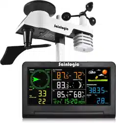
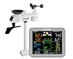
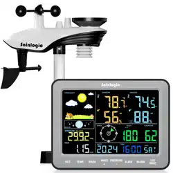
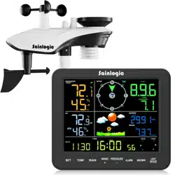
The weather station consists of a display console (receiver) and one
thermo-hygrometer Sensor (remote transmitters).
Note: Power up the sensors with battery first, and the Display Console
with adapter second, don’t press any button until all data is received.
1.1Parts List
QTY
Item
1
Display Console
Frame Dimensions (LxHxW): 8.5X0.87X6.2inch
LCD Dimensions (LxW): 6.7 x 4.92inch
1
Thermo-hygrometer Sensor
1
Manual
1
Power Adapter
2. Weather Station Power On
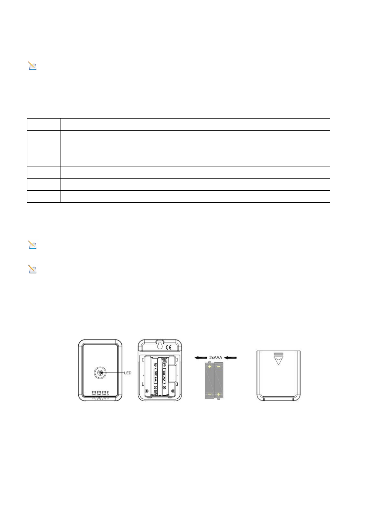
2.1 Thermo-hygrometer Sensor
Note: To avoid permanent damage, please take note of the battery
polarity before inserting the batteries.
Note:Lithium batteries are recommended for cold weather
environments.
1. Open the battery compartment as shown below. Insert two fresh AAA
batteries(with the negative terminal of the battery in contact with each
spring).
2. The LED shown in Figure 1 will light up (visible through the plastic).
Figure 1
3.
It is recommended you mount the thermo-hygrometer sensor outside in
a shaded area. A north facing wall is preferred because it is in the shade
most of the day. Direct sunlight and radiant heat sources will result in
inaccurate temperature readings. Although the sensor is not waterproof, it
is best to mount in a well protected area, such as under an eve.
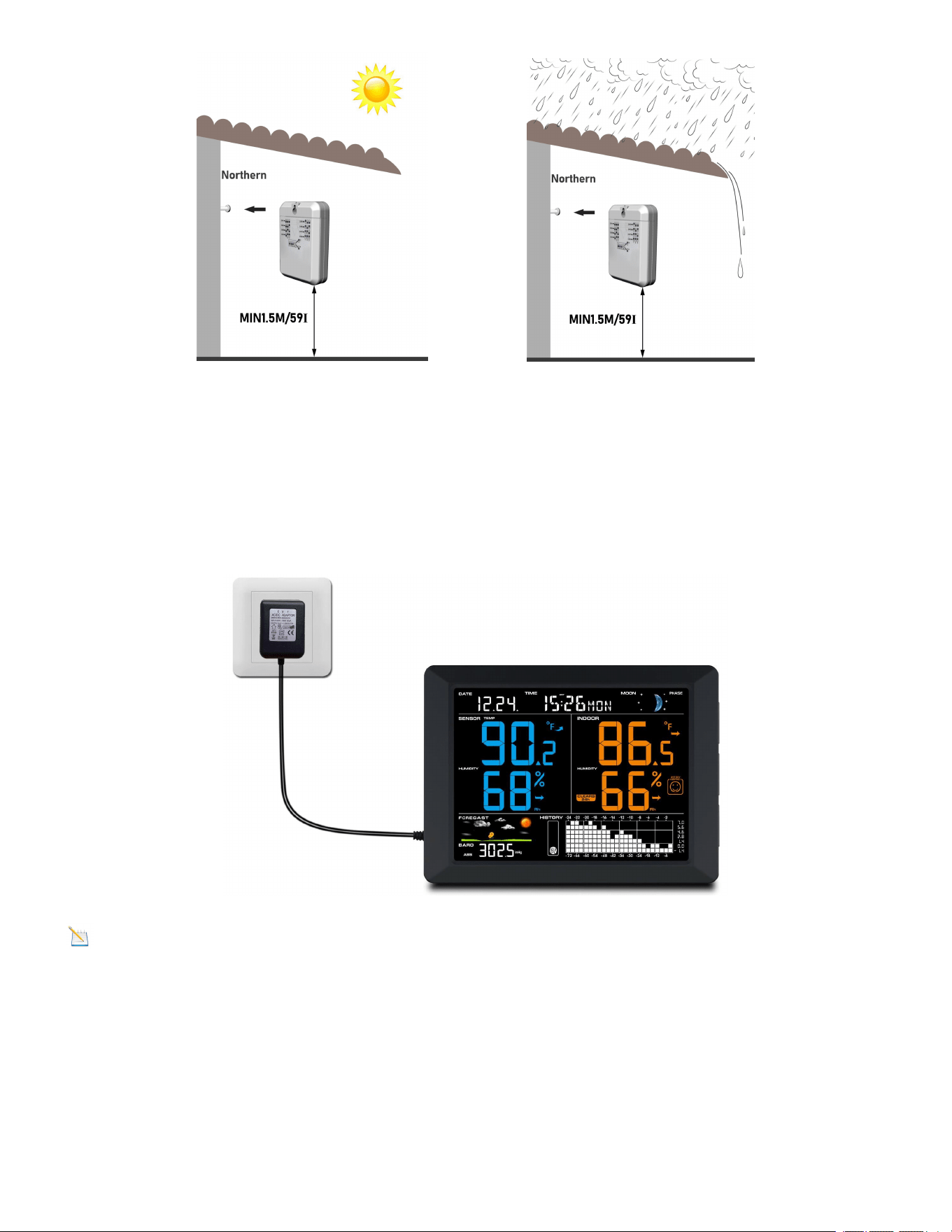
4
Keep out sun Keep out rain
Figure 2
2.2 Display Console
1.Power on with adapter to keep the backlight on. The battery is a back-up
option, saving console settings when powered off from adaptor.
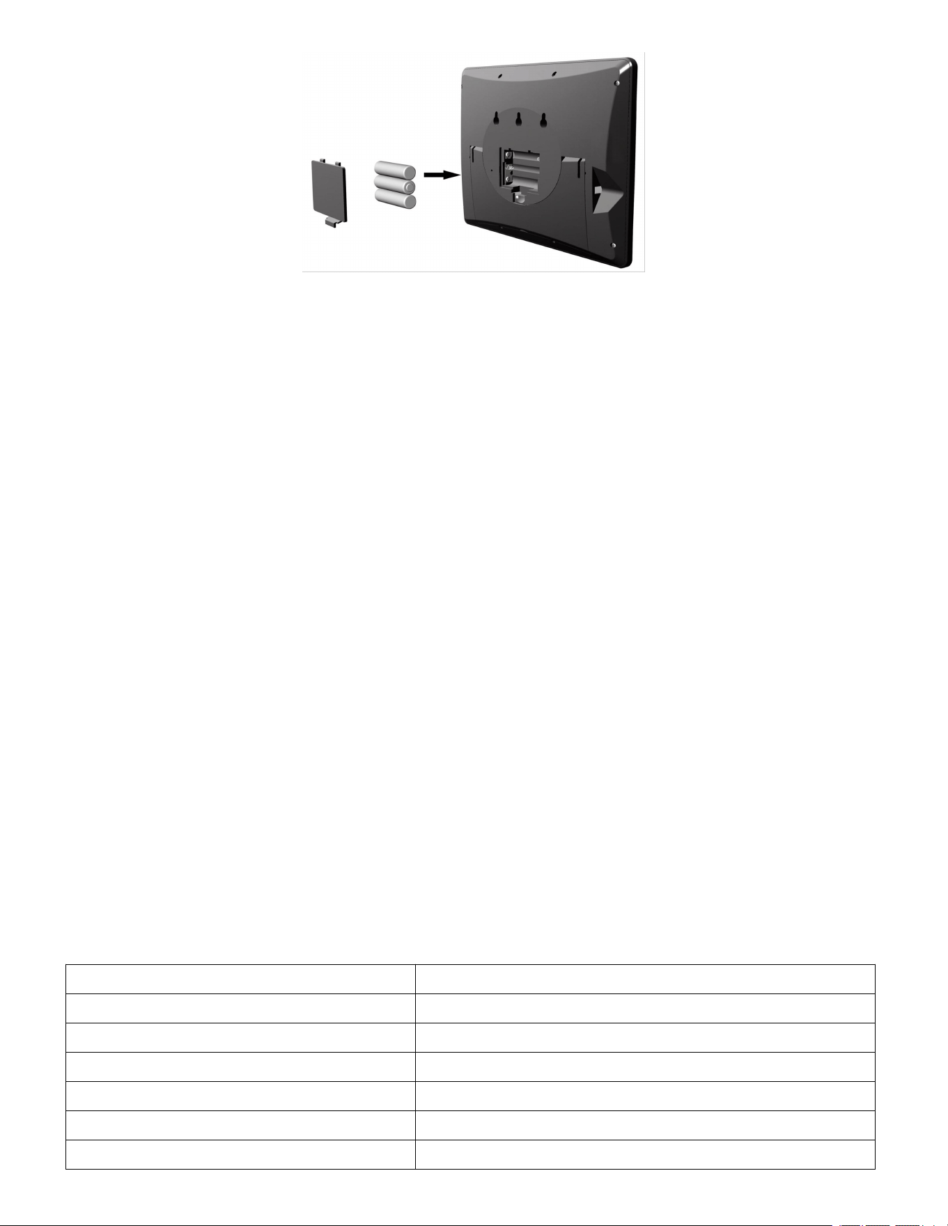
Note: Power the console with an adapter first, not the batteries,
otherwise the backlight will not light on constantly.
2. Remove the battery door on the back of the display, install 3xAAA
batteries and close the door, place on the desk or mount on the wall.
Figure 3
5
Figure 4
3. Weather Station Installation
3.1 Best Practices for Wireless Communication
Wireless communication is susceptible to interference, distance, walls and
metal barriers. We recommend the following best practices for trouble free
wireless communication.
1. Electro-Magnetic Interference (EMI). Keep the console several feet
away from computer monitors and TVs.
2. Radio Frequency Interference (RFI). If you have other 433 MHz
devices and communication is intermittent, try turning off these other
devices for troubleshooting purposes. You may need to relocate the
transmitters or receivers to avoid intermittent communication.
3. Line of Sight Rating. This device is rated at 300 feet(100m) line of sight
(no interference, barriers or walls) but typically you will get 100 feet(30m)
maximum under most real-world installations, which include passing
through barriers or walls.
4. Metal Barriers. Radio frequency will not pass through metal barriers
such as aluminum siding. If you have metal siding, align the remote and
console through a window to get a clear line of sight.
The following is a table of reception loss vs. the transmission medium.
Each “wall”or obstruction decreases the transmission range by the factor
shown below.
Medium
RF Signal Strength Reduction
Glass (untreated)
5-15%
Plastics
10-15%
Wood
10-40%
Brick
10-40%
Concrete
40-80%
Metal
90-100%
6
4. Low Battery Icon
A low battery indicator icon is shown in the display window for
thermo-hygrometer sensor. When the low battery icon appears (the battery
voltage is lower than 2.4V), replace the batteries in the sensor with fresh
batteries. Be sure to never mix old and new batteries, and never mix
battery types such as alkaline and lithium together.
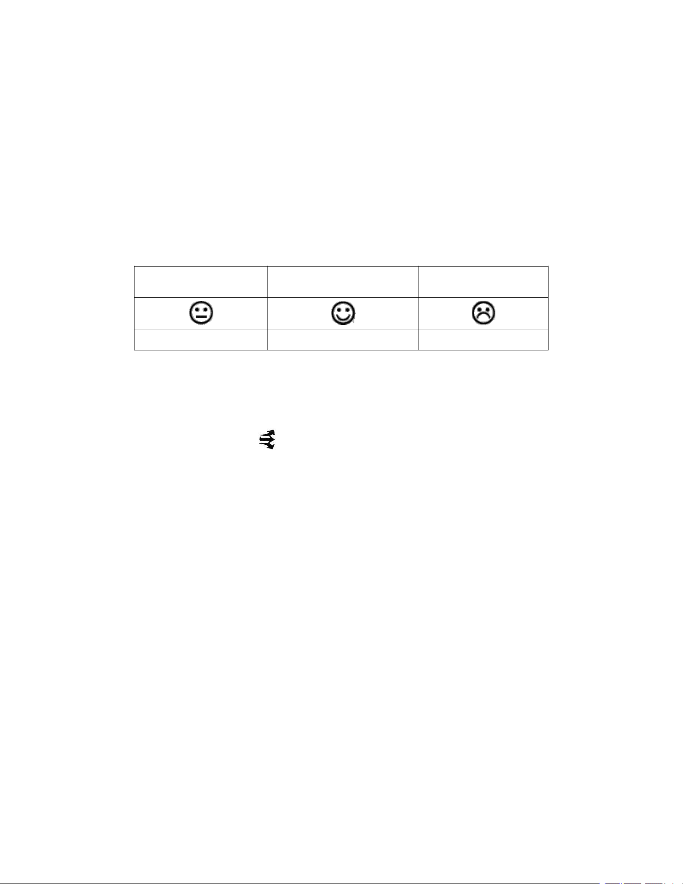
4.1 Comfort Icon
The comfort icon is based on humidity ranges specified in Figure 5. The
icon is displayed for indoor humidity.
RH<45%
RH 45%~65%
RH >65%
Dry
Comfortable
Wet
Figure 5
4.2 Rate of Change Icon
The rate of change icon detects rapid changes in temperature and
humidity.
If the arrow points upward, the temperature is increasing at a rate of +2°F
per 30 minutes (or greater). If the arrow points downward, the temperature
is decreasing at a rate of -2°F per 30 minutes (or less).
If the arrow points upward, the humidity is increasing at a rate of +5% per
30 minutes (or greater). If the arrow points downward, the humidity is
decreasing at a rate of -5% per 30 minutes (or less).
5. Radio Controlled Clock (RCC)
After the console is powered up, it starts synchronizing with remote sensor
for 3 minutes, and then the console starts radio controlled clock (RCC)
reception. During the RCC reception period (maximum 10 minutes), no
weather data is transmitted to avoid interference.
If RCC is not successfully received within 10 minutes, RCC reception
process will stop temporarily and automatically resume every one hour
until the signal is successfully captured. The regular communication
between indoor console and remote sensor will resume once RCC
7
reception process is finished. In some locations, RCC reception may take a
couple of days to receive the signal.
6. Display Console Features
6.1 Quick Set Mode
Note: The console has five keys for easy operation: HISTORY/- key,
ALARM key, SET/MODE key, CHANNEL/+ key and SNOOZE key.
Note: To exit the Quick SET Mode at any time, press the SNOOZE
button of the display console.
While in Normal Mode, press (do not hold) the SET/MODE key repeatedly
to enter into below 4 modes:
once for date and year.
twice times for outdoor temperature and dew point.
three times for pressure absolute (ABS) and relative(REL).
four times for 72h or 24h graph record
1. Date and Year. Press the HISTORY/- key to toggle between year and
date.
2. Temperature and Dew point. Press the HISTORY/- key to toggle
between temperature and dew point for outdoor.
3. Absolute Pressure and Relative Pressure. Press the CHANNEL/+ or
HISTORY/- key to toggle between absolute pressure and relative
pressure.
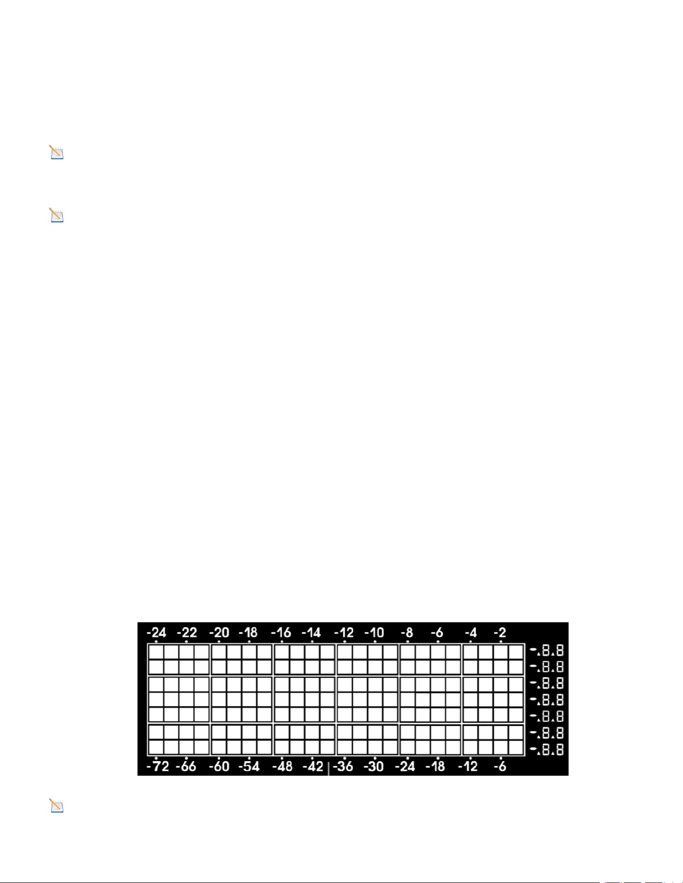
4. 72h or 24h Graph Record. Press the CHANNEL/+ or HISTORY/- key
to toggle between the last -72 hours or -24 hours record time. Each bar
represents the corresponding data and time for pressure, temperature
or humidity.( default is -72 hours),as shown in Figure 6.
Figure 6
Note: The graph displays hours on the horizontal or x-axis (the most
recent data to the right of the graph). For example, 0h is the current data

8
and -12 is 12 hours ago. The vertical axis or y-axis auto-scales, displays
the deviation from the current value (the most recent data will always
display 0). For example, when in temperature mode, if the bar displays 0.4,
this represents 0.4 degrees higher than the current value.
6.2 Set (Program) Mode
While in Normal Mode, press and hold the SET/MODE key for at least
three seconds to enter the Set Mode. The first setting will begin flashing.
You can press the SET key again to skip any step, as defined below.
Note: In the Set mode, press the [+] key or [-] key to change or scroll
the value. Hold the [+] key or [-] key for three seconds to
increase/decrease rapidly.
Note: To exit the Set mode at any time, press the SNOOZE button of
the display console.
1.Radio Controlled Clock(RCC)(default: ON)
Press and hold the SET/MODE key to set the RCC. The RCC (ON or OFF)
setting will begin flashing. Press the [+] key or [-] key to toggle between
RCC ON (adjusts automatically to the atomic clock) and RCC OFF (uses
the quartz clock).
Note: The time and date display is based on the signal provided by the
highly accurate government operated atomic clock in Fort Collins, CO. The
base station will continue to scan for the radio controlled time signal each
day at 2:00, despite if you manually set the date and time.
If reception is unsuccessful, the radio controlled time icon will not appear
but reception attempts will continue.
If reception has been successful, the received time and date will overwrite
the manually set time and date. Once the radio controlled time is received,
the RCC reception icon will turn on.
2.Daylight Saving Time Settings (default: OFF). The DST (ON or OFF)
setting will begin flashing. Press the [+] key or [-] key to toggle between
DST ON (adjusts automatically to the atomic clock) and DST OFF (uses
the quartz clock).The console has been programmed to automatically
switch when daylight saving time is in effect. Your console will display
“DST”.
Note: Arizona does not observe daylight savings time. If you live in
Arizona and DST is in effect, you will need to change your time zone to -8
9
for Pacific.
3.Time Zone Settings (default: 0H). Press the SET key again to adjust
the Time Zone (TZ) setting. Press the [+] key or [-] key to adjust the time
zone from -12 to 12, based on the number of hours from Coordinated
Universal Time, or Greenwich Mean Time (GMT).
The following table provides times zones throughout the world. Locations
in the eastern hemisphere are positive, and locations in the western
hemisphere are negative.
Hours
from GMT
Time Zone
Cities
-12
IDLW: International Date Line
West
---
-11
NT: Nome
Nome, AK
-10
AHST: Alaska-Hawaii Standard
CAT: Central Alaska
HST: Hawaii Standard
Honolulu, HI
-9
YST: Yukon Standard
Yukon Territory
-8
PST: Pacific Standard
Los Angeles, CA, USA
-7
MST: Mountain Standard
Denver, CO, USA
-6
CST: Central Standard
Chicago, IL, USA
-5
EST: Eastern Standard
New York, NY, USA
-4
AST: Atlantic Standard
Caracas
-3
---
São Paulo, Brazil
-2
AT: Azores
Azores, Cape Verde
Islands
-1
WAT: West Africa
---
0
GMT: Greenwich Mean
WET: Western European
London, England
1
CET: Central European
Paris, France
2
EET: Eastern European
Athens, Greece
3
BT: Baghdad
Moscow, Russia
4
---
Abu Dhabi, UAE
5
---
Tashkent
6
---
Astana
7
---
Bangkok
8
CCT: China Coast
Bejing
9
JST: Japan Standard
Tokyo

10
10
GST: Guam Standard
Sydney
11
---
Magadan
12
IDLE: International Date Line
East
NZST: New Zealand Standard
Wellington, New
Zealand
4.12/24 Hour Format (default: 12h). Press the SET/MODE key again to
adjust the 12/24 hour format setting (FMT). Press the [+] key or [-] key
to change between 12 hour and 24 hour format.
5.Change Hour. Press the SET/MODE key again to set the hour. Press
the [+] key or [-] key to adjust the hour up or down.
6.Change Minute. Press the SET/MODE key again to set the minute.
Press the [+] key or [-] key to adjust the minute up or down.
7.Date Format (default: MM-DD). Press the SET/MODE key again to
enter the day/month format mode. Press the [+] key to switch between
MM-DD, DD-MM.
8.Change Month. Press the SET/MODE key again to set the calendar
month. Press the [+] key or [-] key to adjust the calendar month.
9.Change Day. Press the SET/MODE key again to set the calendar day.
Press the [+] key or [-] key to adjust the calendar day.
10.Change Year. Press the SET/MODE key again to set the calendar year.
Press the [+] key or [-] key to adjust the calendar year.
11.Max/Min Clearing (default: ON). Press the SET/MODE key again to
set the max/min clearing mode (CLR). The Max/Min can be
programmed to clear daily (at midnight) or manually. Press the [+] key or
[-] key to switch between ON “Clears 24h” and OFF “Clears Manually”.
12.Temperature Units of Measure (default: °F). Press the SET/MODE
key again to change the temperature units of measure (the UNIT SET
icon will be displayed). Press the [+] key or [-] key to switch between °F
and °C units of measure.
13.Barometric Pressure Display Units (default: inHg). Press the
SET/MODE key again to change the pressure units of measure. Press
the [+] key or [-] key to toggle the pressure units between mmHg, inHg
or hPa.
14.Weather Forecast Icon Setting (default: partly cloudy). Press the
SET/MODE key again to set the weather forecast icon initial conditions
(based on the current weather conditions). Press the [+] key or [-] key to
toggle weather icons between sunny, partly cloudy, cloudy, or rainy.
15.Backlight Adjust Contrast Setting (default: OFF). Press the

11
SET/MODE key again to change the backlight automatic dimming of
display at night (the AUTO BL icon will be displayed). Press the [+] key or
[-] key to adjust the backlight between OFF and ON.
15.1 Backlight automatic Contrast Setting ON (default: 1). Press the
SET/MODE key again to change the backlight contrast (the DIMMING icon
will be displayed). Press the [+] key or [-] key to adjust contrast from 0 (off),
1 (dim), 2 (mid) to 3 (bright).
15.2 Change Start Hour for backlight adjustment (default: PM8:01).
Press the SET/MODE key again to change the start time of the backlight
(the STA icon will be displayed). Press the [+] key or [-] key to adjust the
hour up or down.
15.3 Change Start Minute for backlight adjustment (default: PM8:01).
Press the SET/MODE key again to change the start time of the backlight
(the STA icon will be displayed). Press the [+] key or [-] key to adjust the
minute up or down.
15.4 Change End Hour for backlight adjustment(default: 8:00am).
Press the SET/MODE key again to change the end time of the backlight
(the END icon will be displayed). Press the [+] key or [-] key to adjust the
hour up or down.
15.5 Change End Minute for backlight adjustment(default: 8:00am).
Press the SET/MODE key again to change the end time of the backlight
(the END icon will be displayed). Press the [+] key or [-] key to adjust the
minute up or down.
Note: To ensure that backlight does not affect sleep quality, you can
choose your preferred automatic backlight brightness or automatic
shutdown mode at a specified time period at night.
If powered by the adaptor and the backlight is shutdown, when alarm is
triggered the backlight turns on at the same time, and backlight turns off
when alarm is inactive.
Note: Press the HISTORY/- key and install the battery simultaneously,
RESET word shows on display and the console is restored to factory
default settings.

12
6.3 Sensor Search Mode
If the sensor communication is lost, dashes (--.-) will be displayed on the
screen. Press and hold the CH/+ button for 3 seconds to reacquire the
signal, press SET/MODE key to exit, the search icon will be displayed
constantly for 3 minutes. Once the signal is reacquired, the remote search
icon will turn off, and the current values will be displayed.
6.4 History Graph Mode
The historical graph on the display changed to display the measured
parameters.
In normal mode, press the HISTORY/- key to toggle between:
The barometer graph (the BAROREL icon is displayed)
Indoor temperature graph (the TEMP-IN icon is displayed)
Indoor humidity graph (the HUMI-IN icon is displayed)
Outdoor temperature graph (the TEMPOUT icon is displayed)
Outdoor humidity graph (the HUMIOUT icon is displayed)
6.5 Reset Min/Max record
In normal mode, press (do not hold) the ALARM key, the MAX icon will be
displayed. Press the HISTORY/- key to view pressure (ABS or REL) and
temp or dew point(outdoor) max value.
Next, press and hold the SET/MODE key for three seconds to clear the
maximum values of pressure, temperature and humidity. The maximum
values will now display the current values.
Press the ALARM key again (do not hold), the MIN icon will be displayed.
Press the HISTORY/- key to view pressure (ABS or REL) and temp or dew
point(outdoor) min value.
Next, press and hold the SET/MODE key for three seconds to clear the
minimum values of pressure, temperature and humidity. The minimum
values will now display the current values.
Press the SNOOZE key to exit the min/max checking and cleaning mode,
return to normal display mode.

13
6.6 Snooze Mode
When the time alarm sounds with icon flashing, but you wish to silence
the alarm, press the SNOOZE key, the backlight will turn on. The alarm
icon will continue to flash and the alarm will silence for five minute.
Press any key (HISTORY/-, SET/MODE, ALARM, CHANNEL/+) to
permanently exit the Snooze mode.
6.7 Back light Mode
The backlight operation with batteries is different from operation in AC
power.
Backlight Operation, Battery Power
If the back light is off, to turn on the back light temporarily for five seconds,
press the SNOOZE button.
To turn on the backlight for 30 minutes, press and hold the SNOOZE button
for two seconds, and display BL ON icon will be displayed for three
seconds in the time field.
To turn off the backlight at any time, press and hold the SNOOZE button for
two seconds, and display BL OFF icon will be displayed for three seconds
in the time field.
Backlight Operation, AC Power (Included)
Press the SNOOZE button once in quick succession to three level
backlight brightness adjustable. The backlight has three variations of light.
ADJUSTABLE BACKLIGHT (high-bright, mid-bright, low-bright , off)
When the display icon BL ON in light mode.
There are 3 levels of adjustable backlight brightness. Press SNOOZE key
to toggle between
* Backlight off,
* Power saving level,
* General level,
* Bright level.
To turn off the backlight permanently, press and hold the SNOOZE key for
two seconds, and display BL OFF icon will be displayed for three seconds
in the time field.
To turn on the backlight permanently, press and hold the SNOOZE key for
two seconds, and display BL ON icon will be displayed for three seconds in
the time field.

14
Note: If plugged into AC power, the time area will display AC ON and the
backlight will remain on.
If the automatic backlight setting is turned ON and the dimming is selected
as 0 (off), the backlight is automatically turned off during the set period.
For example, the backlight is set to automatically turn off from 8:01pm to
8:00am next day. During this period, to turn on the backlight temporarily for
five seconds, press the SNOOZE button.
7. Adjustment or Calibration
Note: The calibrated value can only be adjusted on the console.
Note: The measured humidity range is between 10 and 99%. Humidity
cannot be accurately measured outside of this range. Thus, the humidity
cannot be calibrated below 10% or above 99%.
The purpose of calibration is to fine tune or correct for any sensor error
associated with the devices margin of error. The measurement can be
adjusted from the console to calibrate to a known source.
Calibration is only useful if you have a known calibrated source you can
compare it against, and is optional. This section discusses practices,
procedures and sources for sensor calibration to reduce manufacturing
and degradation errors. Do not compare your readings obtained from
sources such as the internet, radio, television or newspapers. They are in a
different location and typically update once per hour.
The purpose of your weather station is to measure conditions of your
surroundings, which vary significantly from location to location.
7.1 Temperature Calibration
In normal mode, press and hold the SET/MODE and CHANNEL/+ keys at
the same time for five seconds to enter the temperature calibration mode.
The indoor temperature will begin flashing.
Press the [+] or [-] key to increase or decrease the temperature reading (in
increments of 0.1). Press and hold the [+] or [-] key for three seconds to
increase or decrease rapidly.

15
Press the ALARM key to reset current value.
Press the SET/MODE key switch to sensor temperature calibrated mode.
Press the SET/MODE key switch to exit calibrated mode.To exit the
calibration mode at any time, press the SNOOZE button on the right side of
the display console. If no operation is performed, the calibration mode will
timeout in 30 seconds.
7.2 Humidity Calibration
In normal mode, press and hold the SET/MODE and HISTORY/- keys at
the same time for five seconds to enter the humidity calibration mode. The
indoor humidity will begin flashing.
Press the [+] or [-] key to increase or decrease the humidity reading (in
increments of 1%). Press and hold the [+] or [-] key for three seconds to
increase or decrease rapidly.
Press the ALARM key to reset current value.
Press the SET/MODE key switch to sensor humidity calibrated mode.
Press the SET/MODE key switch to exit calibrated mode.To exit the
calibration mode at any time, press the SNOOZE button on the right side of
the display console. If no operation is performed, the calibration mode will
timeout in 30 seconds.
Note: Humidity is a difficult parameter to measure accurately and drifts
over time. The calibration feature allows you to zero out this error. To
calibrate humidity, you will need an accurate source, such as a sling
psychrometer or Humidipaks One Step Calibration kit.
7.3 Pressure Calibration
In normal mode, press and hold the SET/MODE and ALARM keys at the
same time for five seconds to enter the pressure calibration mode. The
ABS of pressure will begin flashing.
Press the [+] or [-] key to increase or decrease the pressure reading.
Press and hold the [+] or [-] key for three seconds to increase or decrease
rapidly.
Press the ALARM key to reset current value.
Press the SET/MODE key switch to REL of pressure calibrated mode.
Press the SET/MODE key switch to exit calibrated mode. To exit the
calibration mode at any time, press the SNOOZE button on the right side of

16
the display console. If no operation is performed, the calibration mode will
timeout in 30 seconds.
1. Absolute Pressure Calibration
Press the SET/MODE key again to enter the pressure calibration mode.
Press the [+] or [-] key to increase or decrease the pressure reading (in
increments of 0.00 inHg))
2. Relative Pressure Calibration
In the calibration mode, press the SET/MODE button again, the “REL”
symbol will display at the pressure section, the relative pressure value will
flash. (The default value is 0.00 inHg)
Press the [+] or [-] key to increase or decrease the relative pressure value
(in increments of 0.01 inHg).
Press and hold the [+] or [-] for three seconds to increase or decrease
rapidly.
Press the ALARM key to reset current value.
Example: The calibrated pressure sources measure 25.00
inHg. The display console pressure reads 24.85 inHg.
Offset = 25.00 - 24.85 = 0.15 inHg
Note: The display console displays two different pressures: absolute
(measured) and relative (corrected to sea-level).
To compare pressure conditions from one location to another,
meteorologists correct pressure to sea-level conditions. Because the air
pressure decreases as you rise in altitude, the sea-level corrected
pressure (the pressure your location would be as if located at sea-level) is
generally higher than your measured pressure.
Thus, your absolute pressure may read 28.62 inHg (969 mb) at an altitude
of 1000 feet (305 m), but the relative pressure is 30.00 inHg (1016 mb).
The standard sea-level pressure is 29.92 in Hg (1013.2hpa). This is the
average sea-level pressure around the world. Relative pressure
measurements greater than 29.92 inHg (1013.2hpa) are considered high

17
pressure and relative pressure measurements less than 29.92 inHg are
considered low pressure.
To determine the relative pressure for your location, locate an official
reporting station near from you (the internet is the best source for real-time
barometer conditions, such as the website of Weather.com or
Wunderground.com), and set your weather station to match the official
reporting station.
8. Alarm Mode
The weather station includes time alarm, temperature alarm and humidity
alarm features for indoor and sensor, dew point alarm for sensor and
pressure (ABS and REL) alarm.
8.1 Alarm Operation
When an alarm condition is exceeded, the alarm icon will flash (visual)
and the alarm beeper will sound (audible). Press any keys can silence the
beeper.
8.2 Viewing the High and Low Alarms
To view the current alarm settings, press and hold the ALARM key for
three seconds to enter the alarm mode. Alarm time and other HI alarm
parameters are displayed.
Press the SET/MODE key to view temp/dew point, pressure(ABS and REL)
high alarm.
Press the ALARM key to view the LOW alarm. Alarm time and other Low
alarm parameter displayed.
Press the SET/MODE key to view temp/dew point, pressure(ABS and REL)
low alarm.
Press the SNOOZE key at any time to return to the normal mode.
8.3 Setting the Alarms
In alarm mode(press and hold the ALARM key for three seconds), press
and hold the SET/MODE key for three seconds. The alarm parameter will
begin flashing. To adjust the alarm parameter, press the [+] or [-] key to
increase or decrease the alarm setting slowly, or press and hold the [+] or

18
[-] key for three seconds to increase or decrease the alarm setting rapidly.
Press the ALARM key to turn on (the alarm icon will appear ) and off
the alarm.
To save the alarm setting and proceed to the next alarm parameter, press
(do not hold) the SET/MODE key.
Press the SNOOZE key twice at any time to return to the normal mode.
After 30 seconds of inactivity, the alarm mode will time out and return to
normal mode.
The following is a list of the individual alarm parameters that are set (in
order):
1.Alarm hour
2.Alarm minute
3.Sensor temperature high alarm
4.Sensor temperature low alarm
5.Sensor humidity high alarm
6.Sensor humidity low alarm
7.Sensor dew point high alarm
8.Sensor dew point low alarm
9.Indoor temperature high alarm
10.Indoor temperature low alarm
11. Indoor humidity high alarm
12.Indoor humidity low alarm
13.Absolute pressure high alarm
14.Absolute pressure low alarm
15.Relative pressure high alarm
16.Relative pressure low alarm
8.4 Alarm and Command Key Beeper ON/OFF Mode
The beeper can be silenced for both alarms and key strokes.
In normal mode, press and hold the HISTORY/- key for three seconds to
toggle the beeper on or off (depending on the current setting).
The BUZZ ON (beeper on) or BUZZ OFF (beeper off) icon will appear in
the time area for three seconds. Press and hold the HISTORY/- key again
for three seconds to toggle the BUZZ ON or BUZZ OFF command.
9. Other Console Features
The following section describes additional features and display icons.
9.1 Weather Forecasting
Note: The weather forecast or pressure tendency is based on the rate of
19
change of barometric pressure. In general, when the pressure increases,
the weather improves (sunny to partly cloudy) and when the pressure
decreases, the weather degrades (cloudy to rain).
The weather forecast is an estimation or generalization of weather
changes in the next 24 to 48 hours, and varies from location to location.
The tendency is simply a tool for projecting weather conditions and is
never to be relied upon as an accurate method to predict the weather.
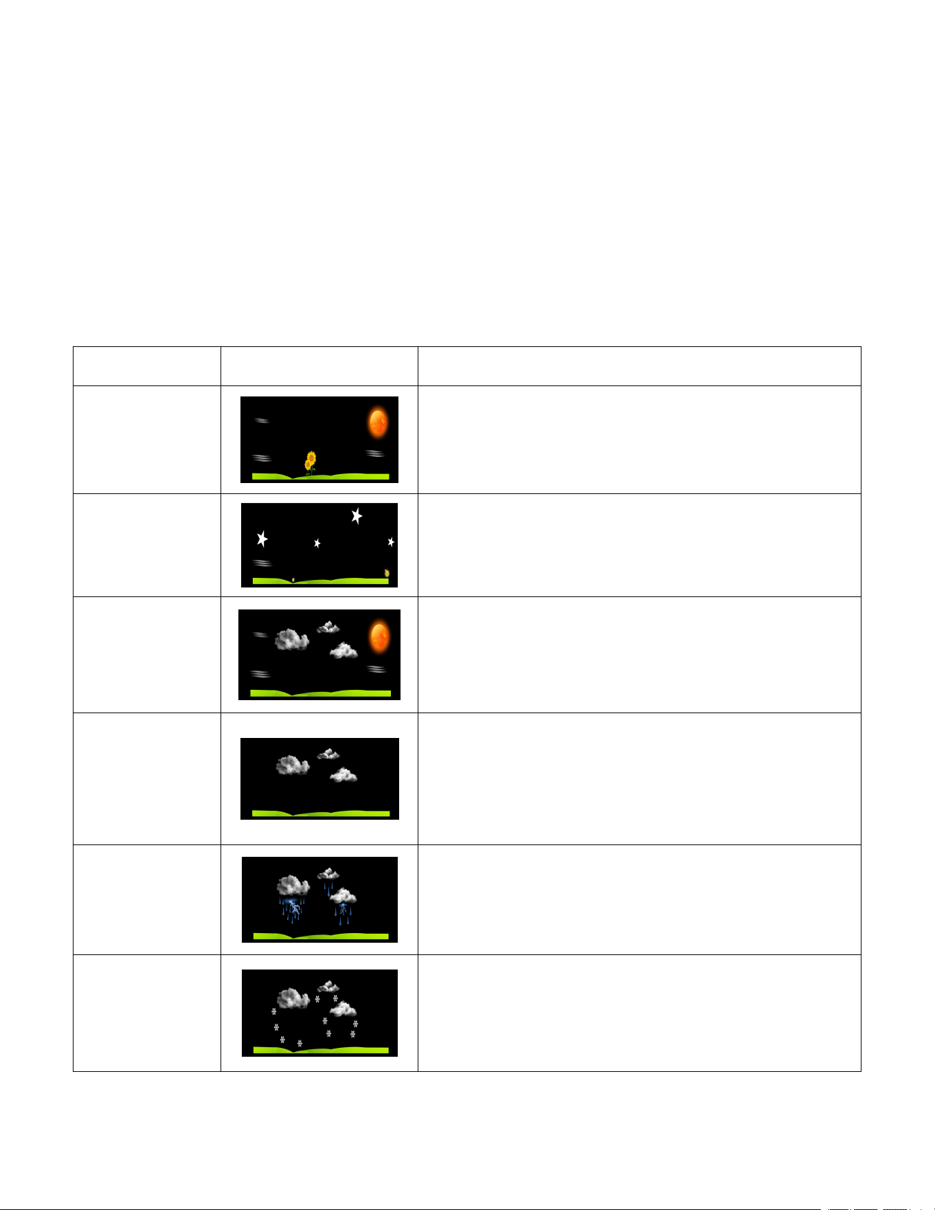
9.2 Weather Icons
Condition
Icon
Description
Sunny
Pressure is rising and the previous
condition is partly cloudy.
Stars and
Moon
On a sunny day, between 7:00pm and
7:00am (night time), the stars will be
displayed instead of the sunny icon.
Partly
Cloudy
Pressure is falling and the previous
condition is sunny or Pressure is rising
and the previous condition is cloudy.
Cloudy
Pressure is falling and the previous
condition is partly cloudy or Pressure is
rising and the previous condition is
rainy.
Rainy
Pressure is falling and the previous
condition is cloudy
Snowy
Pressure is falling and the previous
condition is cloudy(snowy icon will
display on rainy day and outdoor
temperature below 32 °F)
Figure 7
20
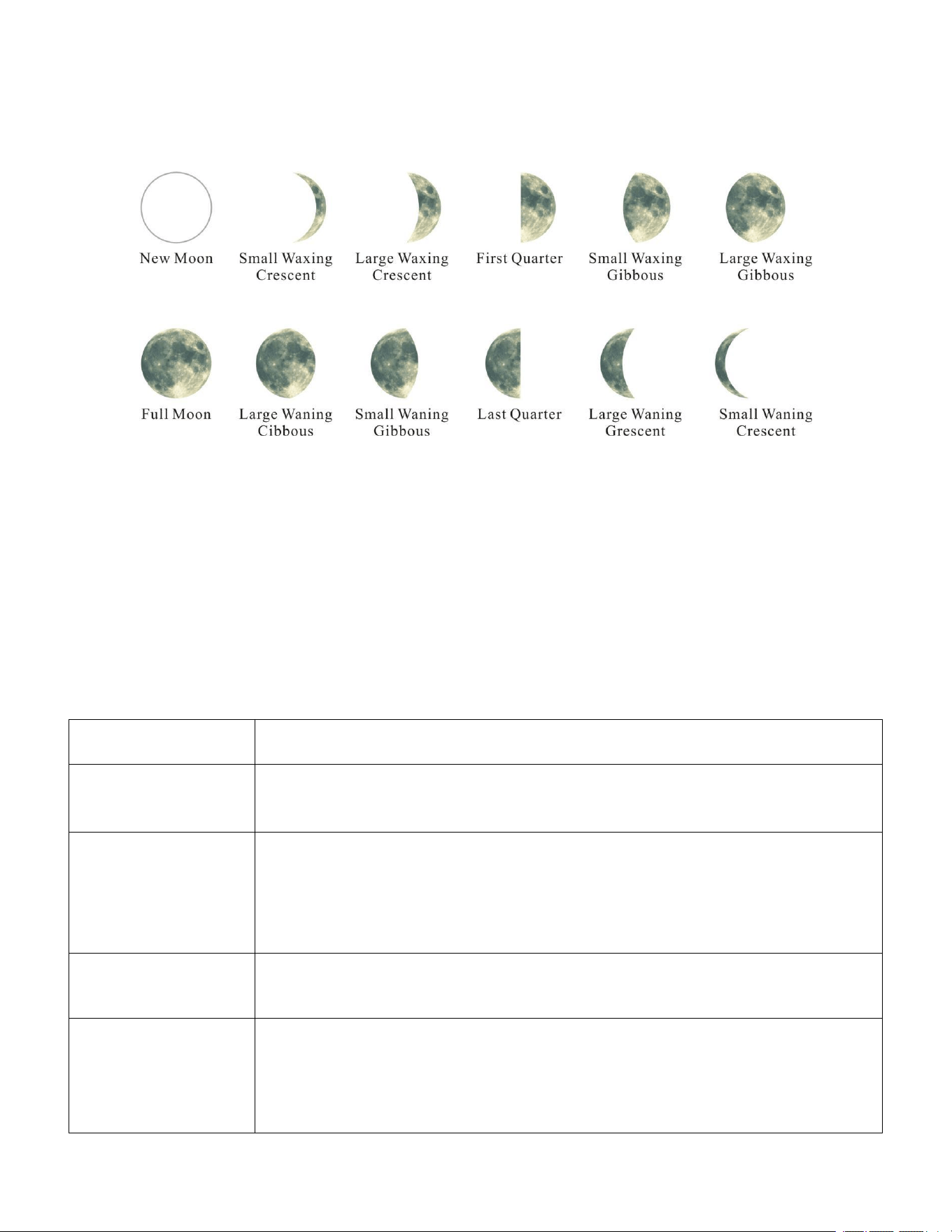
9.3 Moon Phase
The following moon phases are displayed based on the calendar date, as
shown in Figure 8 .
Figure 8
9.4 Restore Factory Default
To reset the display console to factory default (display), press the
HISTORY/- key while plugging in power adaptor at the same time (Take out
batteries before starting the reset operation).
10. Glossary of Terms
Term
Definition
Accuracy
Accuracy is defined as the ability of a measurement to
match the actual value of the quantity being measured.
Hygrometer
A hygrometer is a device that measures relative
humidity. Relative humidity is a term used to describe
the amount or percentage of water vapor that exists in
air.
Range
Range is defined as the amount or extent a value can
be measured.
Resolution
Resolution is defined as the number of significant digits
(decimal places) to which a value is being reliably
measured.
21
Term
Definition
Absolute
Barometric
Pressure
Relative barometric pressure, corrected to sea-level. To
compare pressure conditions from one location to
another, meteorologists correct
pressure to sea-level conditions. Because the air
pressure decreases as you rise in altitude, the sea-level
corrected pressure (the pressure your location would be
at if located at sea-level) is generally higher than your
measured pressure.
Relative
Barometric
Pressure
Measured barometric pressure relative to your location
or ambient conditions.
HectoPascals
(hPa)
Pressure units in SI (international system) units of
measurement. Same as millibars (1 hPa = 1 mbar)
Inches of
Mercury (inHg)
Pressure in Imperial units of measure.
1 inch of mercury = 33.86 millibars
11. Specifications
11.1 Wireless Specifications
Line of sight wireless transmission (in open air): 300ft. 100ft under most
conditions
Frequency: 433 MHz
Update Rate: 60 seconds for thermo-hygrometer sensor
11.2 Measurement Specifications
The following table provides specifications for the measured parameters.
Measurement
Range
Accuracy
Resolution
Indoor
Temperature
32 to 140°F
± 2°F
0.1°F
Outdoor
Temperature
-40 to 140°F
± 2°F
0.1°F
Indoor
Humidity
10 to 99 %
± 5% (only guaranteed
between 20 to 90%)
1 %
22
Measurement Range Accuracy Resolution
Outdoor
Humidity
10 to 99%
± 5% (only guaranteed
between 20 to 90%)
1 %
Barometric
Pressure:
8.85 to 32.50
inHg
± 0.08 inHg 0.01 inHg
11.3 Power Consumption
Base station (display console): 3 x AAA 1.5V Alkaline or Lithium
batteries (not included)
Adaptor: 5.9V~ 500mA (included)
Thermo-hygro Sensor: 2 x AAA alkaline batteries or Lithium batteries
(not included)
Problem Solution
Wireless remote not
reporting in to console.
There are dashes (--.-)
on the display console
1. Clean the Thermo-hygrometer once every 3 months
2. Replace the thermo-hygrometer transmitter batteries once every 3
months.
Battery life: Batteries
in
base
stations
with
good
reception will last
at least 3 months.
Intermittent reception may shorten battery life.
(Use lithium batteries in cold climates below -20 °C).
13. Troubleshooting Guide
.
If the sensor communication is lost, dashes
(--.-) will be displayed on the screen. To
reacquire the signal, press and hold the
CHANNEL/+ button for 3 seconds, the remote
search icon will be constantly displayed.
Once the signal is reacquired, the remote
search icon will turn off, and the current
values will be displayed.
The maximum line of sight communication
range is 300ft and 100ft under most conditions.
Move the sensor assembly closer to the
display console.
23
Problem
Solution
If the sensor assembly is too close (less than
5ft), move the sensor assembly away from the
display console.
Make sure the remote sensor LCD display is
working and the transmitter light is flashing
once per 60 seconds.
Install a fresh set of batteries in the remote
thermo-hygrometer. For cold weather
environments, install lithium batteries.
Make sure the remote sensors are not
transmitting through solid metal (acts as an RF
shield), or earth barrier (down a hill).
Move the display console around electrical
noise generating devices, such as computers,
TVs and other wireless transmitters or
receivers.
Move the remote sensor to a higher location.
Move the remote sensor to a closer location.
Temperature sensor
reads too high in the
day time.
Make sure the thermo-hygrometer is mounted
in a shaded area. The pre preferred location is
a north facing wall because it is in the shade
most of the day.
Indoor and Outdoor
Temperature do not
agree
Allow up to one hour for the sensors to
stabilize due to signal filtering. The indoor and
outdoor temperature sensors should agree
within 4 °F (the sensor accuracy is ± 2 °F).
Use the calibration feature to match the indoor
and outdoor temperature to a known source.
Indoor and Outdoor
Humidity do not agree
Allow up to one hour for the sensors to
stabilize due to signal filtering. The indoor and
24
Problem
Solution
outdoor humidity sensors should agree within
10 % (the sensor accuracy is ± 5 %).
Use the calibration feature to match the indoor
and outdoor humidity to a known source.
Display console contrast
is weak
Replace console batteries with a fresh set of
batteries.
The atomic clock signal
is weak or no signal
A minimum distance of 8feet to all sources of
Interference , such as televisions or computer
monitors.
Radio reception is weaker in rooms with
concrete walls (e.g.: in cellars) and in offices.
In such circumstances, place the device close
to the window .
The atomic signal is
strong but the wrong
time
Make sure your time zone is set correctly.
Signal reception is normally better at night and
when the weather is clear. The atomic signal
generally takes 2~5 days to synchronize, so it
is important to manually set the time and date
after powering on the display.
Do not set the time or
date, and alarm
While in Normal Mode, press and hold the
SET/MODE key for at least three seconds to
enter the Set Mode.
While in Normal Mode, press and hold the
ALARM key for three seconds to enter the
alarm mode, Then press and hold the
SET/MODE key for three seconds. The alarm
parameter will begin flashing.
The wrong day of the
week displayed
Please make sure that the year, month, and
day are all set correctly.
Do not sound for both
alarms and key strokes
In normal mode, press and hold the
HISTORY/- key for three seconds to turn the
beeper on.

25
14. FCC Statement
Statement according to FCC part 15.19:
This device complies with part 15 of the FCC rules. Operation is subject to
the following two conditions:
1. This device may not cause harmful interference.
2. This device must accept any interference received, including
interference that may cause undesired operation.
Statement according to FCC part 15.21:
Modifications not expressly approved by this company could void the
user's authority to operate the equipment.
Statement according to FCC part 15.105:
Note: This equipment has been tested and found to comply with the
limits for a Class B digital device, pursuant to Part 15 of the FCC Rules.
These limits are designed to provide reasonable protection against harmful
interference in a residential installation. This equipment generates, uses
and can radiate radio frequency energy and, if not installed and used in
accordance with the instructions, may cause harmful interference to radio
communications.
However, there is no guarantee that interference will not occur in a
particular installation. If this equipment does cause harmful interference to
radio or television reception, which can be determined by turning the
equipment off and on, the user is encouraged to try to correct the
interference by one or more of the following measures:
•
Reorient or relocate the receiving antenna.
• Increase the separation between the equipment and receiver.
• Connect the equipment into an outlet on a circuit different from that to
which the receiver is connected.
• Consult the dealer or an experienced radio/TV technician for help.

Manufacturer:
Sainlogic HighTech Innovation Co.,
LTD
F9,De Zhong Industrial Park,
Li Pu Street,Shenzhen,China
Post:518001
www.sainlogic.com
Email:[email protected]
Skype:+15087580493
WhatsApp:+852 68715461
FCCID: 2ALHJ-WS016T