
ENGLISH
FRANÇAISDEUTSCH
NEDERLANDS
ESPAÑOLITALIANO
PORTUGUÊS
SVENSKA
Owner’s Manual
M15
AV Surround Sound Preamplifier
®

ENGLISH FRANÇAIS
DEUTSCH
NEDERLANDS
ESPAÑOL
ITALIANO
PORTUGUÊS
SVENSKA
2
IMPORTANT SAFETY INSTRUCTIONS
IMPORTANT SAFETY INSTRUCTIONS
• Save these instructions for later use.
• Follow all warnings and instructions marked on the audio equipment.
1 Read instructions - All the safety and operating instructions should be read before the
product is operated.
2 Retain instructions - The safety and operating instructions should be retained for future
reference.
3 Heed Warnings - All warnings on the product and in the operating instructions should be
adhered to.
4 Follow Instructions - All operating and use instructions should be followed.
5 Cleaning - Unplug this product from the wall outlet before cleaning. Do not use liquid
cleaners or aerosol cleaners. Use a damp cloth for cleaning.
6 Attachments - Do not use attachments not recommended by the product manufacturer as
they may cause hazards.
7 Water and Moisture - Do not use this product near water-for example, near a bath tub,
wash bowl, kitchen sink, or laundry tub; in a wet basement; or near a swimming pool; and
the like.
8 Accessories - Do not place this product on an unstable cart, stand, tripod, bracket, or table.
The product may fall, causing serious injury to a child or adult, and serious damage to the
product. Use only with a cart, stand, tripod, bracket, or table recommended by the
manufacturer, or sold with the product. Any mounting of the product should follow the
manufacturer’s instructions, and should use a mounting accessory recommended by the
manufacturer.
9 A product and cart combination should be moved with care. Quick stops, excessive force,
and uneven surfaces may cause the product and cart combination to overturn.
10 Ventilation - Slots and openings in the cabinet are provided for ventilation and to ensure
reliable operation of the product and to protect it from overheating, and these openings must
not be blocked or covered. The openings should never be blocked by placing the product on
a bed, sofa, rug, or other similar surface. This product should not be placed in a built-in
installation such as a bookcase or rack unless proper ventilation is provided or the
manufacturer’s instructions have been adhered to.
11 Power Sources - This product should be operated only from the type of power source
indicated on the marking label. If you are not sure of the type of power supply to your home,
consult your product dealer or local power company.
• Main Power Disconnect; When the power switch is in the Off position, the preamplifier
is not completely disconnected from the main power. The primary method of isolating the
preamplifier from the mains supply is to disconnect the mains plug. Ensure that the mains
plug remains accessible at all times. When installing the product, ensure that the plug is
easily accessible.
• Non-use Period; Unplug the AC power cord from the AC outlet if the unit will not be
used for a long period of time such as several months or more.
• CLASS 1 Products; The M15 shall be connected to a MAINS socket outlet with a protective
earthing connection.

ENGLISH
FRANÇAISDEUTSCHNEDERLANDSESPAÑOL
ITALIANO
PORTUGUÊS
SVENSKA
3
IMPORTANT SAFETY INSTRUCTIONS
12 Power-Cord Protection - Power-supply cords should be routed so that they are not likely
to be walked on or pinched by items placed upon or against them, paying particular attention
to cords at plugs, convenience receptacles, and the point where they exit from the product.
13 Outdoor Antenna Grounding - If an outside antenna or cable system is connected to
the product, be sure the antenna or cable system is grounded so as to provide some protection
against voltage surges and built-up static charges. Article 810 of the National Electrical Code,
ANSI/NFPA 70, provides information with regard to proper grounding of the mast and
supporting structure, grounding of the lead-in wire to an antenna discharge unit, size of
grounding conductors, location of antenna discharge unit, connection to grounding
electrodes, and requirements for the grounding electrode.
NOTE TO CATV SYSTEM INSTALLER
• This reminder is provided to call the CATV system installer’s attention to Section 820-40 of
the NEC which provides guidelines for proper grounding and, in particular, specifies that
the cable ground shall be connected to the grounding system of the building, as close to
the point of cable entry as practical.
14 Lightning - For added protection for this product during a lightning storm, or when it is
left unattended and unused for long periods of time, unplug it from the wall outlet and
disconnect the antenna or cable system. This will prevent damage to the product due to
lightning and power-line surges.
15 Power Lines - An outside antenna system should not be located in the vicinity of overhead
power lines or other electric light or power circuits, or where it can fall into such power lines
or circuits. When installing an outside antenna system, extreme care should be taken to keep
from touching such power lines or circuits as contact with them might be fatal.
16 Overloading - Do not overload wall outlets, extension cords, or integral convenience
receptacles as this can result in a risk of fire or electric shock.
17 Object and Liquid Entry - Never push objects of any kind into this product through
openings as they may touch dangerous voltage points or short-out parts that could result in
a fire or electric shock. Never spill liquid of any kind on the product.
18 Damage Requiring Service - Unplug this product from the wall outlet and refer servicing to qualified
service personnel under the following conditions:
a) When the power-supply cord or plug is damaged.
b) If liquid has been spilled, or objects have fallen into the product.
c) If the product has been exposed to rain or water.
d) If the product does not operate normally by following the operating instructions. Adjust only those
controls that are covered by the operating instructions as an improper adjustment of other controls
may result in damage and will often require extensive work by a qualified technician to restore the
product to its normal operation.
e) If the product has been dropped or damaged in any way.
f) when the product exhibits a distinct change in performance-this indicates a need for service.
19 Replacement Parts - When replacement parts are required, be sure the service technician has used
replacement parts specified by the manufacturer or have the same characteristics as the original part.
Unauthorised substitutions may result in fire, electric shock, or other hazards.
20 Safety Check - Upon completion of any service or repairs to this product, ask the service technician
to perform safety checks to determine that the product is in proper operating condition.
21 Wall or Ceiling Mounting - The product should be mounted to a wall or ceiling only as
recommended by the manufacturer.
4
WARNING
TO PREVENT FIRE OR SHOCK HAZARD, DO NOT EXPOSE THIS APPLIANCE TO RAIN OR
MOISTURE. THE LIGHTNING FLASH WITH ARROWHEAD SYMBOL, WITHIN AN EQUILATERAL
TRIANGLE, IS INTENDED TO ALERT THE USER TO THE PRESENCE OF UNINSULATED
“DANGEROUS VOLTAGE” WITHIN THE PRODUCT’S ENCLOSURE THAT MAY BE OF SUFFICIENT
MAGNITUDE TO CONSTITUTE A RISK OF ELECTRIC SHOCK TO PERSONS.
THE EXCLAMATION POINT WITHIN AN EQUILATERAL TRIANGLE IS INTENDED TO ALERT THE
USER TO THE PRESENCE OF IMPORTANT OPERATING AND MAINTENANCE (SERVICING)
INSTRUCTIONS IN THE LITERATURE ACCOMPANYING THE APPLIANCE
CAUTION
Changes or modifications to this equipment not expressly approved by NAD Electronics for compliance
could void the user’s authority to operate this equipment.
CAUTION REGARDING PLACEMENT
To maintain proper ventilation, be sure to leave a space around the unit (from the largest outer
dimensions including projections) equal to, or greater than, shown below.
Left and Right Panels : 10 cm
Rear Panel : 10 cm
Top Panel : 50 cm
IMPORTANT INFORMATION FOR UK CUSTOMERS
DO NOT cut off the mains plug from this equipment. If the plug fitted is not suitable for the power points
in your home or the cable is too short to reach a power point, then obtain an appropriate safety approved
extension lead or consult your dealer. If, nonetheless, the mains plug is cut off, REMOVE THE FUSE and
dispose of the PLUG immediately, to avoid possible shock hazard by inadvertent connection to the mains
supply. If this product is not provided with a mains plug, or one has to be fitted, then follow the
instructions given below:
IMPORTANT
DO NOT make any connection to the larger terminal which is marked with the letter ‘E’ or by the safety
earth symbol or coloured GREEN or GREEN AND YELLOW.
The wires in the mains lead on this product are coloured in accordance with the following code:
BLUE - NEUTRAL
BROWN - LIVE
As these colours may not correspond with the coloured markings identifying the terminals in your plug,
proceed as follows:
The BLUE wire must be connected to the terminal marked with the letter ‘N’ or coloured BLACK.
The BROWN wire must be connected to the terminal marked with the letter ‘L’ or coloured RED
When replacing the fuse, only a correctly rated and approved type should be used, and be sure
to re-fit the fuse cover.
IF IN DOUBT CONSULT A COMPETENT ELECTRICIAN
This product is manufactured to comply with the radio interference requirements of EEC DIRECTIVE
89/68/EEC and 73/23/EEC
NOTES ON ENVIRONMENTAL PROTECTION
At the end of its useful life, this product must not be disposed of with regular household waste but must
be returned to a collection point for the recycling of electrical and electronic equipment. The symbol on
the product, user's manual and packaging, point this out.
The materials can be reused in accordance with their markings. Through re-use, recycling of raw
materials, or other forms of recycling of old products, you are making an important contribution to the
protection of our environment.
Your local administrative office can advise you of the responsible waste disposal point.
RECORD YOUR MODEL NUMBER (NOW, WHILE YOU CAN SEE IT)
The model and serial number of your new M15 are located on the back of the cabinet. For your future
convenience, we suggest that you record these numbers here:
SAFETY INFORMATION
Introduction
ENGLISH FRANÇAIS
DEUTSCH
NEDERLANDS
ESPAÑOL
ITALIANO
PORTUGUÊS
SVENSKA
Model No. :________________________Serial No. :_________________

5
TABLE OF CONTENTS
Introduction
ENGLISH
FRANÇAISDEUTSCHNEDERLANDSESPAÑOL
ITALIANO
PORTUGUÊS
SVENSKA
INTRODUCTION
Safety precautions . . . . . . . . . . . . . . . . . . . . . . . . . . . . . . . . . . . .2-4
Table of contents . . . . . . . . . . . . . . . . . . . . . . . . . . . . . . . . . . . . . . .5
Getting Started . . . . . . . . . . . . . . . . . . . . . . . . . . . . . . . . . . . . . . . . .6
About THX . . . . . . . . . . . . . . . . . . . . . . . . . . . . . . . . . . . . . . . . . 6
What’s In The Box . . . . . . . . . . . . . . . . . . . . . . . . . . . . . . . . . . . . . 6
Save The Packing. . . . . . . . . . . . . . . . . . . . . . . . . . . . . . . . . . . . . . 6
Dolby . . . . . . . . . . . . . . . . . . . . . . . . . . . . . . . . . . . . . . . . . . . . . . . 6
DTS . . . . . . . . . . . . . . . . . . . . . . . . . . . . . . . . . . . . . . . . . . . . . . . . 6
THX . . . . . . . . . . . . . . . . . . . . . . . . . . . . . . . . . . . . . . . . . . . . . . . . 6
Quick Start . . . . . . . . . . . . . . . . . . . . . . . . . . . . . . . . . . . . . . . . . . .7-9
IDENTIFICATION OF CONTROLS
Front Panel/Rear Panel . . . . . . . . . . . . . . . . . . . . . . . . . . . . . . . . .10
Remote Controls . . . . . . . . . . . . . . . . . . . . . . . . . . . . . . . . . . . . . . .11
About the M15 . . . . . . . . . . . . . . . . . . . . . . . . . . . . . . . . . . . . .12-15
Front Panel Controls . . . . . . . . . . . . . . . . . . . . . . . . . . . . . . . . . . 12
About the HTRM . . . . . . . . . . . . . . . . . . . . . . . . . . . . . . . . . . . .16-21
Getting Familiar with the HTRM . . . . . . . . . . . . . . . . . . . . . . . . . 16
HTRM SETUP MENU . . . . . . . . . . . . . . . . . . . . . . . . . . . . . . . . . . 17
Navigation of the HTRM Controls . . . . . . . . . . . . . . . . . . . . . . . . 18
HTRM Features . . . . . . . . . . . . . . . . . . . . . . . . . . . . . . . . . . . . . . 19
USB Interface. . . . . . . . . . . . . . . . . . . . . . . . . . . . . . . . . . . . . . . . 21
About the M15 . . . . . . . . . . . . . . . . . . . . . . . . . . . . . . . . . . . . .22-26
Rear Panel Connections and Controls . . . . . . . . . . . . . . . . . . . . . 22
SETUP
Using M15 . . . . . . . . . . . . . . . . . . . . . . . . . . . . . . . . . . . . . . . . .27-34
OSD And Monitor Output . . . . . . . . . . . . . . . . . . . . . . . . . . . . . . 27
Navigation of the On Screen Display (OSD) Menus . . . . . . 27
Audio Control . . . . . . . . . . . . . . . . . . . . . . . . . . . . . . . . . . . . . . . 27
THX/Speaker Setup . . . . . . . . . . . . . . . . . . . . . . . . . . . . . . . . . 28
THX/Bass Management . . . . . . . . . . . . . . . . . . . . . . . . . . . . . . . . 29
THX/Guidelines . . . . . . . . . . . . . . . . . . . . . . . . . . . . . . . . . . . . . . 29
Source Setup . . . . . . . . . . . . . . . . . . . . . . . . . . . . . . . . . . . . . . . . 30
Display Setup. . . . . . . . . . . . . . . . . . . . . . . . . . . . . . . . . . . . . . . . 32
Trigger Setup . . . . . . . . . . . . . . . . . . . . . . . . . . . . . . . . . . . . . . . . 32
Zone 2/MS Out . . . . . . . . . . . . . . . . . . . . . . . . . . . . . . . . . . . . . . 32
Enhanced Stereo . . . . . . . . . . . . . . . . . . . . . . . . . . . . . . . . . . . . . 33
A/V Presets . . . . . . . . . . . . . . . . . . . . . . . . . . . . . . . . . . . . . . . . . 33
Setting Up Audio Video Presets. . . . . . . . . . . . . . . . . . . . . . . . . . 33
Assigning A/V Presets . . . . . . . . . . . . . . . . . . . . . . . . . . . . . . . . . 34
Copying A/V Presets . . . . . . . . . . . . . . . . . . . . . . . . . . . . . . . . . . 34
REFERENCE
Troubleshooting Guide . . . . . . . . . . . . . . . . . . . . . . . . . . . . . . . . .35
M15 Factory Default Settings . . . . . . . . . . . . . . . . . . . . . . . . . . . 35
HTRM Special Functions . . . . . . . . . . . . . . . . . . . . . . . . . . . . . . . 35
Specifications . . . . . . . . . . . . . . . . . . . . . . . . . . . . . . . . . . . . . . . . .36
Notes . . . . . . . . . . . . . . . . . . . . . . . . . . . . . . . . . . . . . . . . . . . . . . . .37

6
ABOUT THX
The M15 A/V preamplifier is certified by THX Ltd as meeting the rigorous requirements of
its home THX/Ultra 2 program for surround controllers. This means that it is capable of
delivering an audio experience equal to that of the finest commercial cinemas when its
superb fundamental performance is combined with the surround enhancements
mandated by the THX/Ultra 2* program.
WHAT'S IN THE BOX:
Packed with your M15 A/V Surround Sound Preamplifier you will find:
•
A removable AC cable
•
The HTRM System remote control with batteries
•
The ZR2 second zone remote control with battery
•
This Owner's Manual
SAVE THE PACKING:
Please save the box and all of the packaging in which your M15 arrived. Should you move
or otherwise need to transport your A/V Surround Sound preamplifier, this is by far the
safest container in which to do so. We've seen too many otherwise perfect components
damaged in transit for lack of a proper shipping carton, so please: Save that box!
DOLBY
*Manufactured under license from Dolby Laboratories.
“Dolby”, “Pro Logic“, and the double-D symbol are trademarks of Dolby Laboratories.
DTS
*”DTS“, ”DTS-ES“, ”Neo:6“, and “DTS 96/24” are trademarks of Digital Theater Systems,
Inc.
THX
*”THX” and “Ultra2” are trademarks of THX Ltd. “THX” may be registered in some
jurisdictions. All rights reserved. Surround EX is a trademark of Dolby Laboratories. Used with
permission.
GETTING STARTED
Introduction
ENGLISH FRANÇAIS
DEUTSCH
NEDERLANDS
ESPAÑOL
ITALIANO
PORTUGUÊS
SVENSKA

7
In case you simply cannot wait to experience the performance of your new NAD M15 A/V
Surround Sound Preamplifier, we provide the following “Quick Start” instructions to get
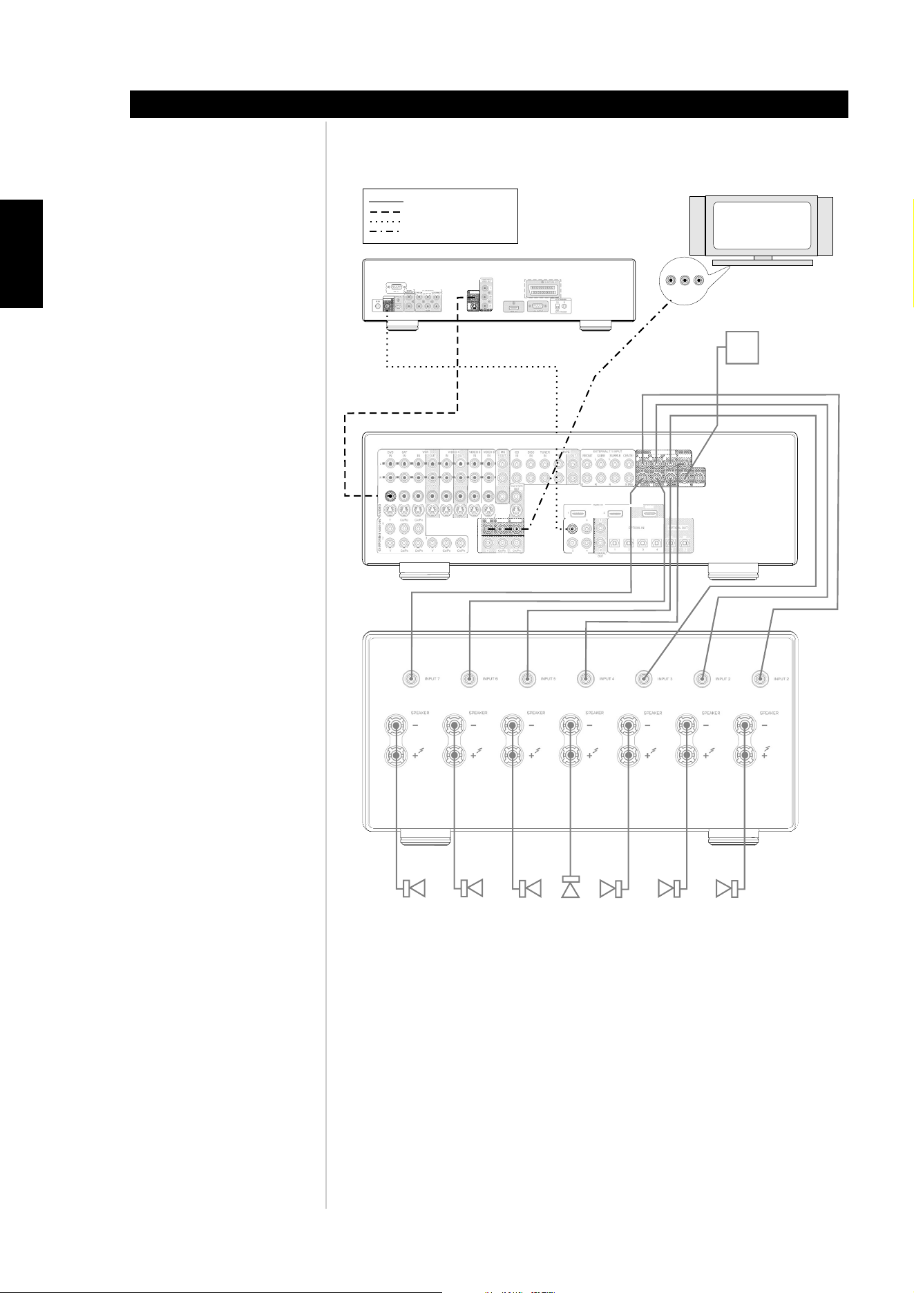
you underway. Follow the steps below for connecting your DVD player, TV/monitor, and
multi-channel amplifier to the M15. (see Figure 2 or Figure 3 depending on the type of
TV/monitor used). We strongly advise that all equipment be switched off and have the
power cables disconnected from the AC-power before proceeding.
FOR TV/MONITORS WITH COMPONENT CONNECTIONS (FIGURE 2)
• Connect the M15’s COMPONENT VIDEO OUT Y-C
B
/P
B
-C
R
/P
R
jack to your TV/monitor’s
corresponding input.
• Connect your DVD player’s Composite output to the M15’s DVD COMPOSITE VIDEO
IN.
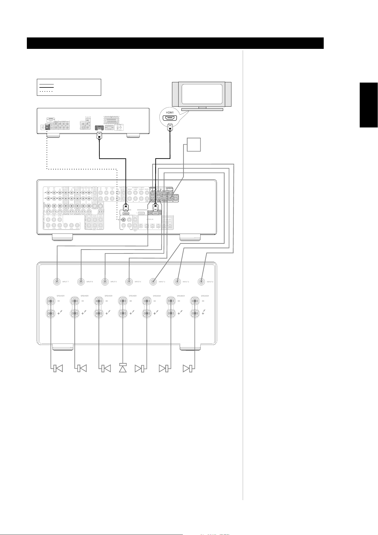
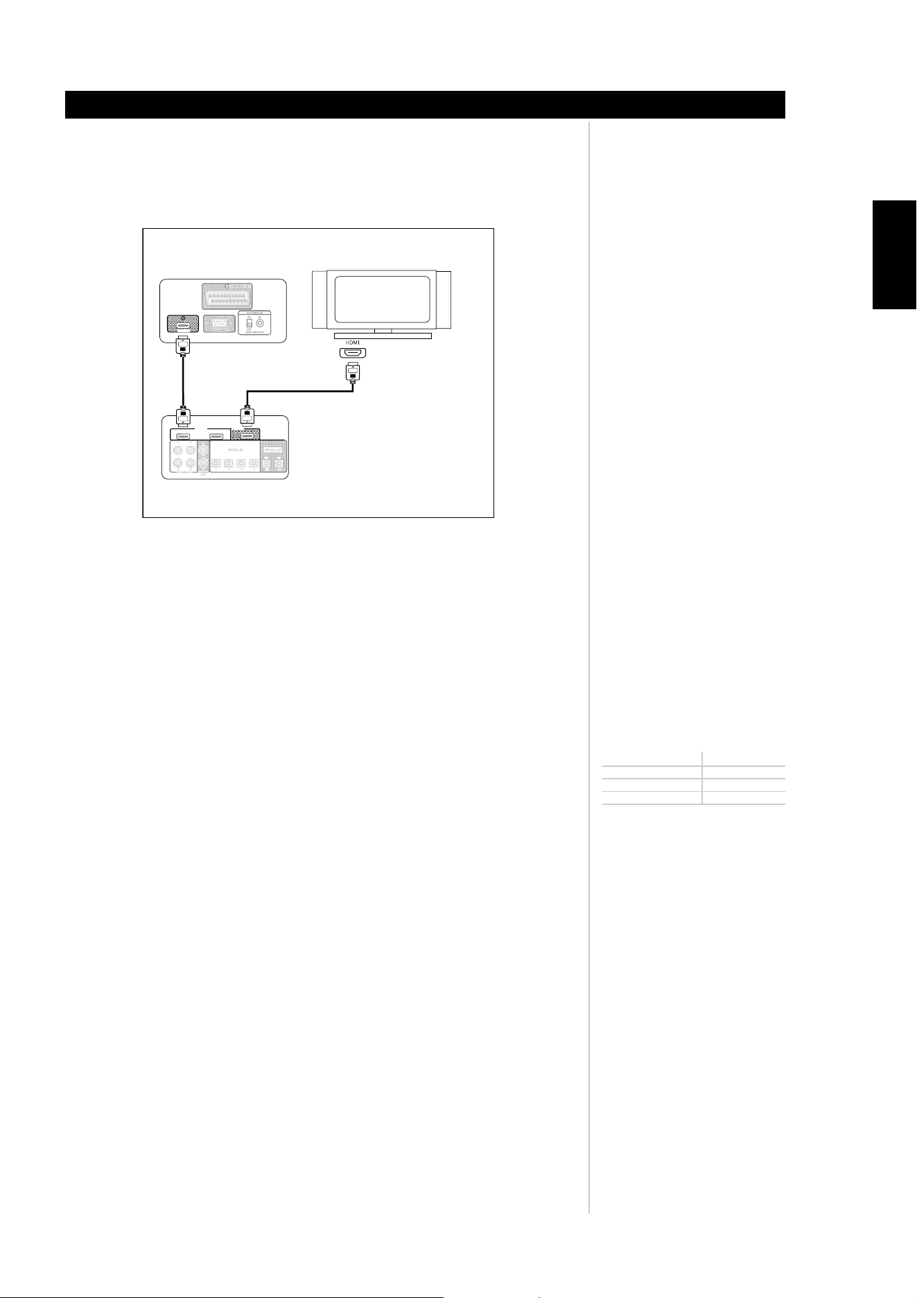
FOR TV/MONITORS WITH HDMI CONNECTIONS (FIGURE 3)
• Connect the M15’s HDMI OUT jack to your TV/monitor’s corresponding HDMI input.
• Connect your DVD player’s HDMI output to the M15’s HDMI IN 1 jack.
AUDIO CONNECTIONS (FIGURE 2 OR FIGURE 3)
• Connect the DVD player’s coaxial digital output to the M15’s COAXIAL IN 1 input
.
• Connect the M15’s AUDIO PRE-OUT outputs to your multi-channel amplifier.
• Connect your speakers to the multi-channel amplifier’s outputs, being sure to connect red
to red (“+”) and black to black (“-”), with care to avoid stray wires or strands crossing
between terminals. (Connect center, surround, and surround-back speakers as well, if
you like). If your system includes a powered subwoofer, connect the M15’s AUDIO PRE-
OUT SUBW1 jack to the subwoofer’s line input.
• Now connect all power cables from the equipment to the AC-power.
• Switch on the black rocker main POWER switch on the M15’s rear panel, see Figure 1
(this puts the M15 into Standby mode and illuminates an amber LED to indicate it is
ready to receive remote commands), and then press any of the front panel buttons to
power up the M15. Be sure the multi-channel amplifier and TV / monitor are powered
up, with the correct input selected.
• Start playback of the DVD player. Press the HTRM remote’s AMP DEVICE SELECTOR
button, and then its DVD1 button to select the DVD input. You should hear
multichannel or stereo sound, and see an
image on the TV/monitor. (If one or the
other fails to appear, you may need to use their preamplifier’s on-screen menu
system to check assignment of audio, video, and digital inputs. Enjoy the movie or
music, but be sure to set aside time to read this manual thoroughly, and to set up,
calibrate, and configure your M15 carefully and completely.
Note: Coaxial, HDMI, and video interconnect cables are not supplied. Please contact
your NAD Dealer for supplying the latest high quality interconnect cables
.
QUICK START
Introduction
ENGLISH
FRANÇAISDEUTSCHNEDERLANDSESPAÑOL
ITALIANO
PORTUGUÊS
SVENSKA
FIGURE 1
8
QUICK START
Introduction
ENGLISH FRANÇAIS
DEUTSCH
NEDERLANDS
ESPAÑOL
ITALIANO
PORTUGUÊS
SVENSKA
Note: the M15’s OSD is available from all the MONITOR OUT sockets except for DIRECT OUT
INPUT 7
INPUT 6
INPUT 5
INPUT 4
INPUT 3
INPUT 2
INPUT 2
FRONT R
FRONT L
SUBWOOFER
SURR R
SURR L
SURR B R
SURR B L
CENTER
SPEAKER
SPEAKER
SPEAKER
SPEAKER
SPEAKER
SPEAKER
SPEAKER
AUDIO CONNECTIONS AND SPEAKERS
KEY:
DISC
IN
TUNER
IN
IN
FRONT
L
R
SURR
L
R
SURR-B
L
EXTERNAL 7.1 INPUT
R
CENTER
SUBW
1
1
2
3
2
13
24
4
COAXIAL IN
OUT
TAPE
HDMI IN
1
2
1
2
1
COMPONENT VIDEO IN
YC/PBB C/PRR
YC/PBB C/PRR
23
YC/P
BB C/PRR
OPTICAL IN OPTICAL OUT
COAXIAL
OUT
R
R
R
CENTER
SUBW1
SUBW2
AUDIO PRE-OUT
FRONT
L
SURR
L
SURR-B
L
CD
IN
MS
OUT
MONITOR
OUT
COMPONENT VIDEO OUT
DIRECT
YC/PBB C/PRR
YC/PBB C/PRR
COMPONENT VIDEO IN
DIRECT
YC/PBB C/PRR
DVD Player
Seven Channel Power Amplifier
DVD
IN
L
R
SAT
IN
VIDEO 5
IN
VIDEO 6
IN
IN
IN
OUT
OUT
VIDEO 4
VCR
S-VIDEO
AUTO TRIGGER
+12V TRIGGER
IR IN
ON
OFF
VIDEO OUT
S VIDEO
COMPONENT
VIDEO OUT
Y
Cb
Pb
Cr
Pr
IN
COAXIAL
OPTICAL
DIGITALOUT
RS 232
SCART/RGB OUT
5.1 CH OUTPUT
L
R
L
R
SUBW
FRONT
CENTER
SURR
MIXED
AUDIO OUT
L
R
VGAOUTPUT
HDMI OUT
Monitor/TV with Component In
HDMI OUT
M15 AV Surround Sound Preamplifier
COMPOSITE VIDEO CONNECTION
COAXIAL DIGITAL CONNECTION
COMPONENT VIDEO CONNECTION
COMPOSITE
VIDEO
FIGURE 2
WARNING! Do not place the M15 directly on top of a Power Amplifier (or any other source of heat
in excess of 35ºC or 95ºF).
Excessive heat caused by inadequate ventilation can affect the performance and longevity of this
precision audio component.
Note: the M15’s OSD is not available from the HDMI OUT socket.
9
QUICK START
Introduction
ENGLISH
FRANÇAISDEUTSCHNEDERLANDSESPAÑOL
ITALIANO
PORTUGUÊS
SVENSKA
INPUT 7
INPUT 6
INPUT 5
INPUT 4
INPUT 3
INPUT 2
INPUT 2
FRONT R
FRONT L
SUBWOOFER
SURR R
SURR L
SURR B R
SURR B L
CENTER
SPEAKER
SPEAKER
SPEAKER
SPEAKER
SPEAKER
SPEAKER
SPEAKER
AUDIO CONNECTIONS AND SPEAKERS
KEY:
HDMI INPUT AND OUTPUTS
DISC
IN
TUNER
IN
IN
FRONT
L
R
SURR
L
R
SURR-B
L
EXTERNAL 7.1 INPUT
R
CENTER
SUBW
1
1
2
3
2
13
24
4
COAXIAL IN
OUT
TAPE
HDMI IN
1
2
1
2
1
COMPONENT VIDEO IN
YC/PBB C/PRR
YC/PBB C/PRR
23
YC/P
BB C/PRR
OPTICAL IN OPTICAL OUT
COAXIAL
OUT
R
R
R
CENTER
SUBW1
SUBW2
AUDIO PRE-OUT
FRONT
L
SURR
L
SURR-B
L
CD
IN
MS
OUT
MONITOR
OUT
COMPONENT VIDEO OUT
DIRECT
YC/PBB C/PRR
YC/PBB C/PRR
DVD Player
Seven Channel Power Amplifier
DVD
IN
L
R
SAT
IN
VIDEO 5
IN
VIDEO 6
IN
IN
IN
OUT
OUT
VIDEO 4
VCR
COMPOSITE
VIDEO
S-VIDEO
AUTO TRIGGER
+12V TRIGGER
IR IN
ON
OFF
VIDEO OUT
S VIDEO
COMPONENT
VIDEO OUT
Y
Cb
Pb
Cr
Pr
IN
COAXIAL
OPTICAL
DIGITALOUT
RS 232
SCART/RGB OUT
5.1 CH OUTPUT
L
R
L
R
SUBW
FRONT
CENTER
SURR
MIXED
AUDIO OUT
L
R
VGAOUTPUT
HDMI OUT
HDMI Compatible TV
Rear of M55 DVD Player
HDMI connection
HDMI OUT
M15 AV Surround Sound Preamplifier
COAXIAL DIGITAL CONNECTION
FIGURE 3
WARNING! Do not place the M15 directly on top of a Power Amplifier (or any other source of heat
in excess of 35ºC or 95ºF).
Excessive heat caused by inadequate ventilation can affect the performance and longevity of this
precision audio component.
1 - 2
4567
3
8 9 10 11 12
13
18
201713121116 14 15
1910987621
4 3 - 5 2 - 43 - 5
10
ENGLISH FRANÇAIS
DEUTSCH
NEDERLANDS
ESPAÑOL
ITALIANO
PORTUGUÊS
SVENSKA
FRONT PANEL (FIGURE 3)
Identification of controls
REAR PANEL (FIGURE 4)
11
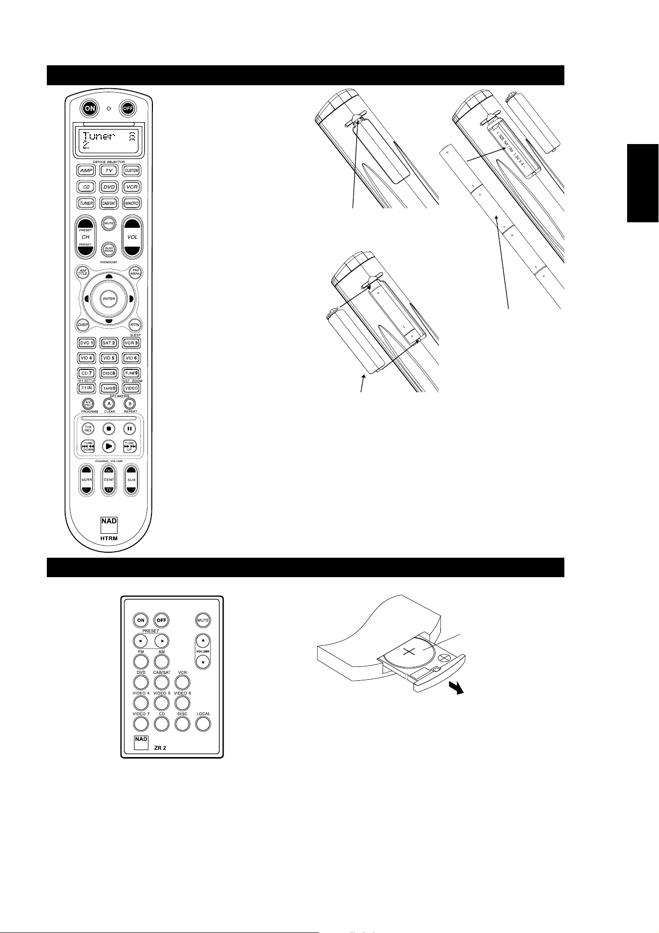
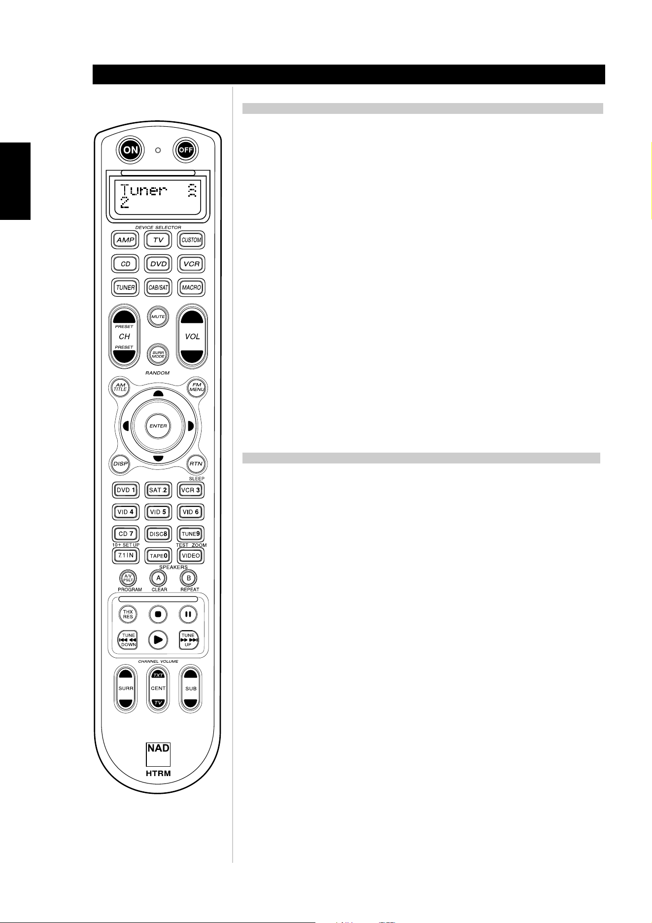
HTRM REMOTE CONTROL (FIGURE 5)
Identification of controls
ENGLISH
FRANÇAISDEUTSCHNEDERLANDSESPAÑOL
ITALIANO
PORTUGUÊS
SVENSKA
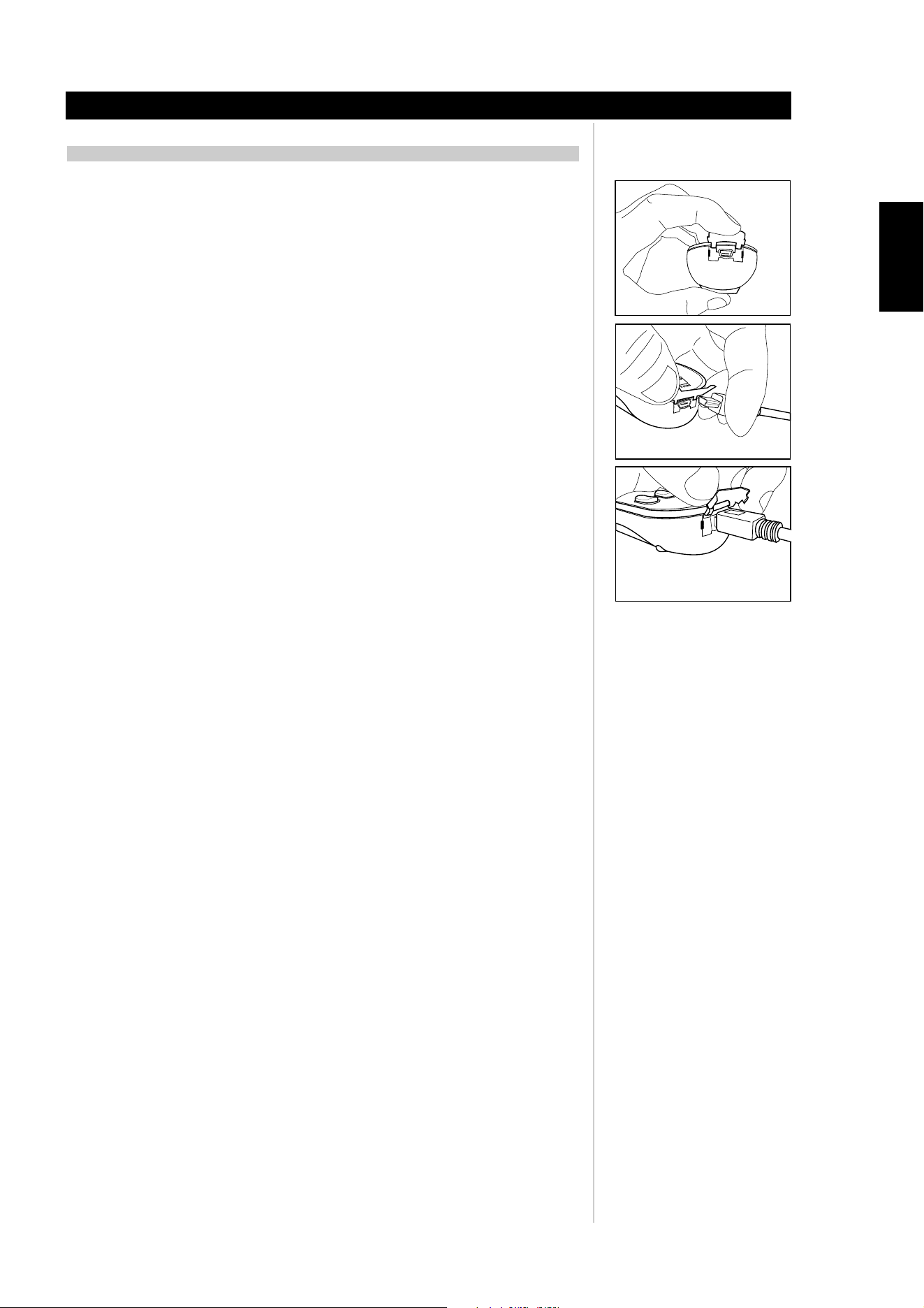
CR2025
OPEN
CR202
5
PRESS IN AND LIFT TAB TO REMOVE
BATTERY COVER OUT FROM RECESS
PLACE BATTERIES INTO OPENING.
ENSURE THE CORRECT POLARITY IS
OBSERVED
PRESS BATTERY COVER INTO PLACE
UNTIL IT 'CLICKS' CLOSED
ZR2 REMOTE CONTROL (FIGURE 6)
• Top section features ON/OFF
buttons and back-light LCD display.
• Upper section has eight DEVICE
SELECTOR keys including one
programmable CUSTOM DEVICE
SELECTOR, one MACRO buttons.
• The upper middle section with
channel, volume, MUTE, surround-
mode buttons
• Middle section has DVD, CD and
OSD navigation buttons
• Lower middle section has number
buttons 0 to 9, A/V PSET,
SPEAKER, function, DVD SETUP,
and receiver’s Surround Mode TEST
buttons
• Lower section has DVD/CD/TAPE
Transport buttons
• Bottom section with CHANNEL
VOLUME trimming buttons
12
ENGLISH FRANÇAIS
DEUTSCH
NEDERLANDS
ESPAÑOL
ITALIANO
PORTUGUÊS
SVENSKA
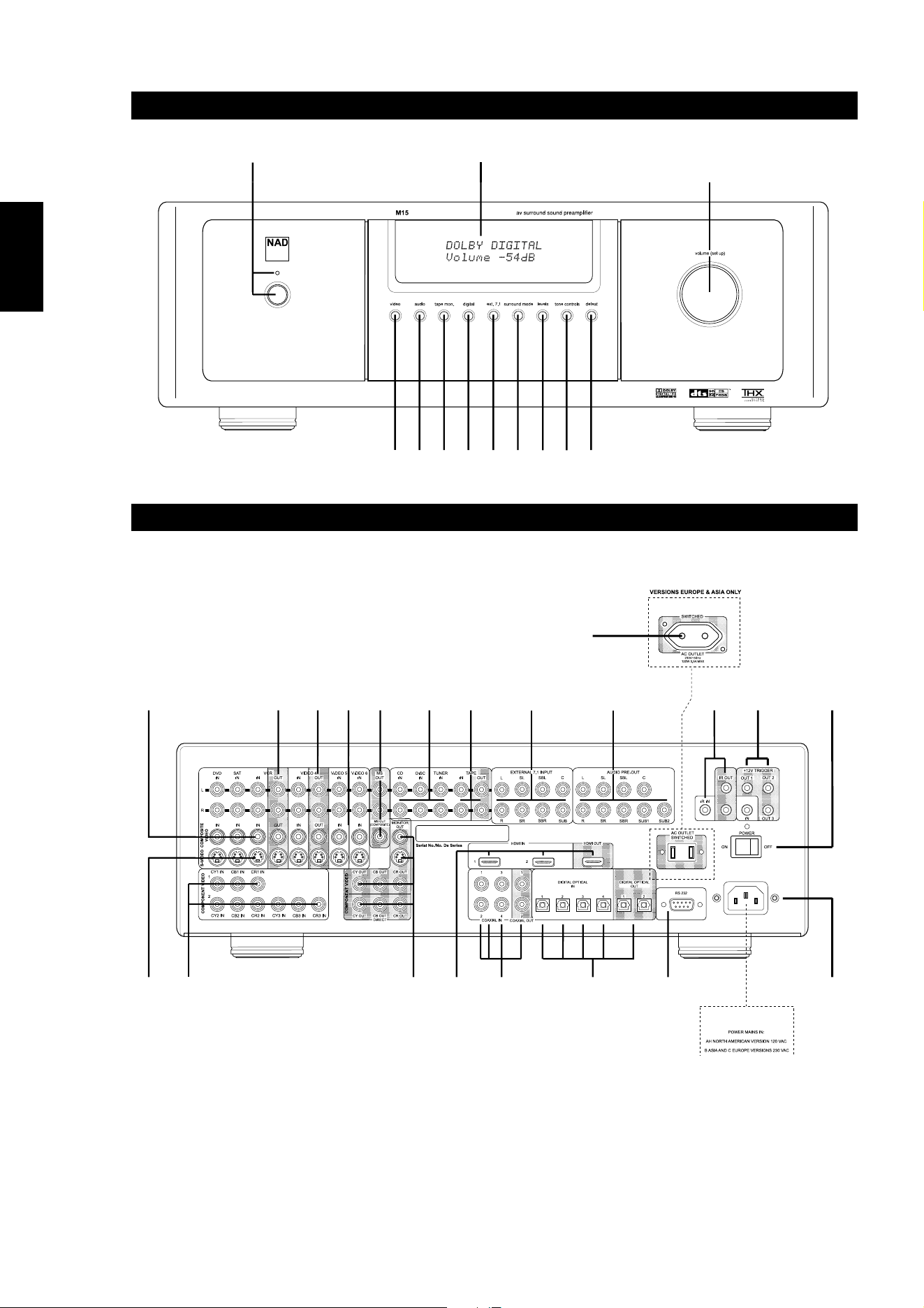
FRONT PANEL CONTROLS
DIAGRAMMATIC REPRESENTATION OF THE FRONT PANEL CONTROLS
1. Power: Switch on and off to enter and exit the Standby mode. The rear panel POWER
switch must be in the ON position for the M15 Power switch to activate.
2. Standby LED: Illuminates blue when the M15 is in the On mode (Amber when the M15
is in standby).
3. Vacuum Florescent Display (VFD): The VFD provides visual information on all of the
M15's important modes, settings, and functions for both main and MS OUT locations.
4. video: Press and hold while simultaneously using the volume (set up) knob to sequentially
select video inputs. The inputs available are; DVD, SAT, VCR, Video 4, Video 5, Video 6,
and then return to DVD.
5. audio: Press and hold while simultaneously using the volume (set up) knob to sequentially
select audio inputs. The inputs available are: CD, DISC, TUNER ,and then back to CD.
6. tape mon.: Press to engage the Tape Monitor loop. The signal present at the rear-panel
TAPE MONITOR IN jacks will be heard.
7. digital: Press and hold while simultaneously using the volume (set up) knob to
sequentially select digital inputs. The digital inputs available are; NONE, COAX 1, COAX
2, COAX 3, COAX 4, OPT 1, OPT 2, OPT 3 OPT 4, then back to NONE. There are four
coaxial as well as four optical inputs.
Note: This association is temporary. The M15 will revert to the settings made in the OSD,
if the M15 was switched to standby or to another source.
ABOUT THE M15
Identification of controls
video + volume
(setup)
audio + volume
(setup)
tape monitor
(toggle on/off)
digital +
volume (setup)
ext 7.1
(toggle on/off)
surround mode +
volume (setup)
levels (toggle) +
volume (setup)
tone controls
(toggle) +
volume (setup)
tone defeat
(toggle on/off)
DVD > SAT > VCR > VIDEO 4
> VIDEO 5 > VIDEO 5 > DVD
CD > DISC > TUNER > CD
bass > treb(treble) > dig(dialog) > bass
TAPE Monitor
7.1 INPUT Analog
tone (on/off)
NONE > COAX 1 > COAX 2 > COAX 3 > COAX 4
> OPT 1 > OPT 2 > OPT 3 > OPT 4 > NONE
Stereo downmix > Mono downmix > DIRECT > Dolby EX >
Dolby EX AUTO (off) > Dolby PLIIx Movie > Dolby PLIIx Music >
DTS or DTS ES or DTS ES Matrix or DTS 96/24 >
NEO:6 Cinema > NEO:6 Music > THX Cinema >
THX Surround EX > PLIIx + THX Cinema > Stereo downmix
FRONT LEFT > CENTER > FRONT RIGHT >
SURR RIGHT > SURR BACK R > SURR BACK L >
> SURR LEFT > SUBWOOFER > FRONT LEFT
13
ENGLISH
FRANÇAISDEUTSCHNEDERLANDSESPAÑOL
ITALIANO
PORTUGUÊS
SVENSKA
8. ext. 7.1: Press to select the 7.1 CH AUDIO IN analog inputs. These inputs bypass the
M15's processor. Tone controls are not available with this input, only Volume control.
9. surround mode: Press and hold while simultaneously using the volume (set up) knob to
sequentially select the surround modes. Depending on the speaker setup, format, and
signal type some surround modes may not be made available.
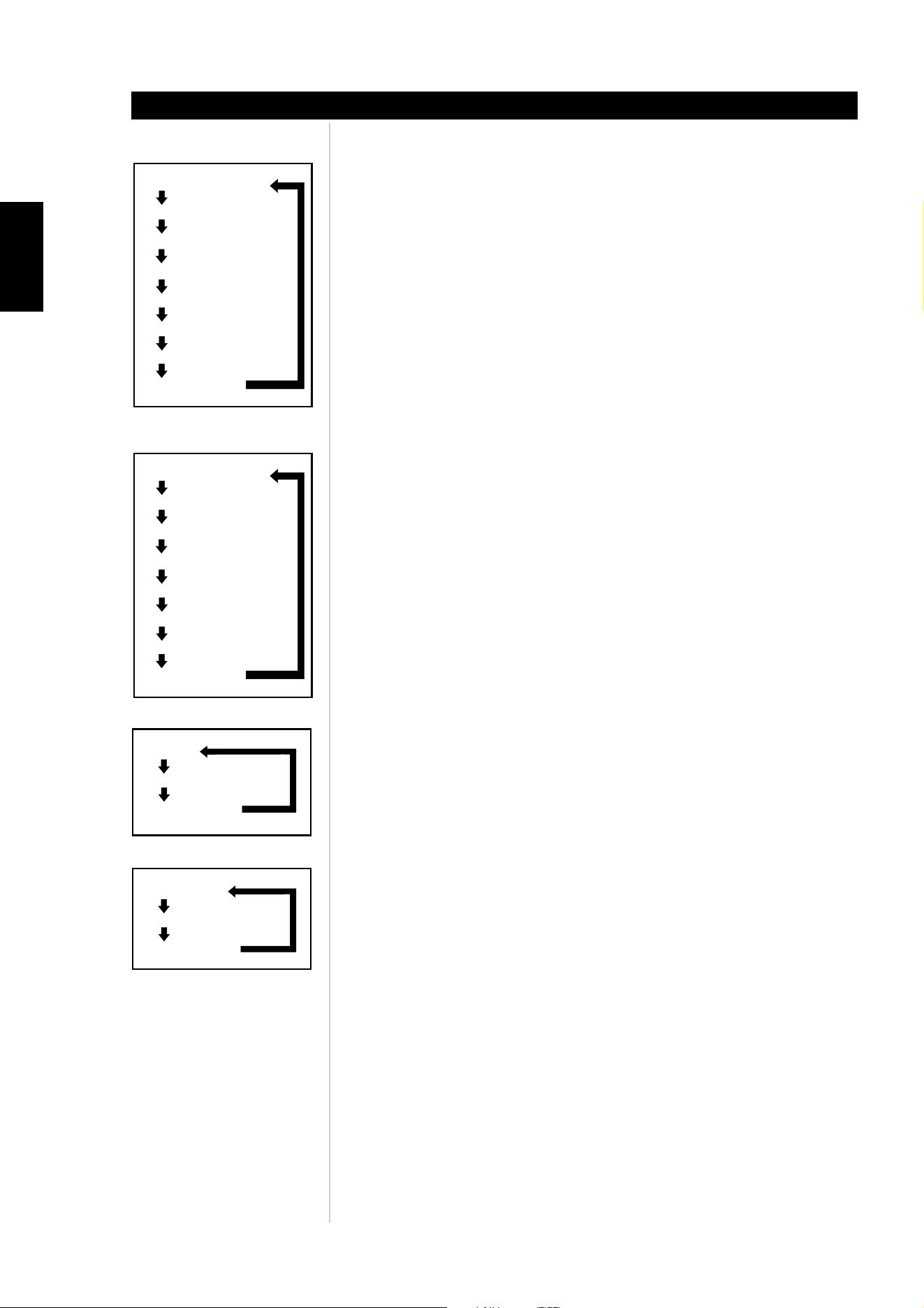
The following are all the possible decoding and post processing options for 2-channel PCM
96kHz with THX option turned on or off. See figure A
The following are all the possible decoding and post processing options for analog inputs
and 2-channel PCM 44.1kHz, 2-channel PCM 48kHz, Dolby Digital 2.0 and DTS 2.0, with
THX option turned off. See figure B
Note: if the surround back speakers are set to "none" then Dolby PLIIx Movie and Music
will be replaced with PLII Movie and Music.
The following are all the possible decoding and post processing options for analog inputs
and 2-channel PCM 44.1kHz, 2-channel PCM 48kHz, Dolby Digital 2.0 and DTS 2.0, with
THX option turned on. See figure C
Note: if the surround back speakers are set to "none" then PLIIx + THX and PLIIx Music will
be replaced with PLII + THX and PLII Music.
The following are all the possible decoding and post processing options for Dolby digital
5.1 inputs with THX option turned off. See figure D
Notes: if the surround back speakers are set to "none" then Dolby Surround EX, Dolby
PLIIx Movie and Music will be skipped.
if the surround back speakers are set to “1 LARGE” or “1 SMALL” then Dolby Surround
EX and Dolby PLIIx will be available.
ABOUT THE M15
Identification of controls
Dolby PLIIx Movie
Dolby PLIIx Music
NEO:6 Cinema
NEO:6 Music
Stereo
Mono
EARS
ENHANCED STEREO
Stereo
Mono
EARS
ENHANCED STEREO
PLIIx + THX Cinema
NEO:6 Cin+THX Cinema
Dolby PLIIx Music
NEO:6 Music
Stereo
Mono
EARS
ENHANCED STEREO
Figure A
Figure B
Figure C
Figure D
DIRECT
Dolby EX
Dolby EX AUTO(off)
Dolby PLIIx Movie
Dolby PLIIx Music
Stereo Downmix
Mono Downmix
14
ENGLISH FRANÇAIS
DEUTSCH
NEDERLANDS
ESPAÑOL
ITALIANO
PORTUGUÊS
SVENSKA
The following are all the possible decoding and post processing options for Dolby Digital
5.1 inputs with THX option turned on. See figure E
Notes: if the surround back speakers are set to "none" then THX Surround EX, PLIIx + THX
Cinema, and THX Ultra2 Cinema, will be skipped, but THX Cinema will then become
available.
if the surround back speakers are set to “1 LARGE” or 1 SMALL” then Dolby Surround
EX, PLII x Music and PLIIx Movie will be available.
The following are all the possible decoding and post processing options DTS 5.1 inputs
with THX option turned on. See figure F
Notes: if the surround back speakers are set to "none" then THX Surround EX, PLIIx + THX
Cinema, and THX Ultra2 Cinema, will be skipped, but THX Cinema will become
available.
The following are all the possible decoding and post processing options for DTS 6.1 ES
Discrete and Matrix inputs with THX option turned off. See figure G
The following are all the possible decoding options DTS 6.1 ES Discrete and Matrix inputs
with THX option turned on. See figure H
Note: if the surround speakers are set to "none" then THX Cinema will be skipped.
The following are all the possible decoding and post processing options for DTS 6.1 ES
Discrete inputs with THX option turned off..See figure G.
The following are all the possible decoding and post processing options for DTS 6.1 ES
Discrete inputs inputs with THX option turned on. See figure H
Note: if the surround speakers are set to "none" then THX Cinema will be skipped.
ABOUT THE M15
Identification of controls
THX Ultra2 Cinema
THX Surround EX
THX Cinema
THX Music Mode
PLIIx + THX Cinema
Dolby PLIIx Music
Stereo Downmix
Mono Downmix
Figure E
THX Ultra2 Cinema
THX Surround EX
THX Cinema
THX Music Mode
PLIIx + THX Cinema
Dolby PLIIx Music
Stereo Downmix
Mono Downmix
DIRECT
Stereo Downmix
Mono Downmix
Stereo Downmix
Mono Downmix
THX Cinema
Figure F
Figure G
Figure H

15
ENGLISH
FRANÇAISDEUTSCHNEDERLANDSESPAÑOL
ITALIANO
PORTUGUÊS
SVENSKA
10 levels: Press to access the VFD menu on the front-panel read-out, and to select speaker
levels using the volume (set up) knob and subsequent presses of the levels key. Each
press of the levels key will advance from one speaker to the other as follows; Front Left,
Center, Front Right, Surround Right, Surround Back Right, Surround Back Left, Surround
Left, Subwoofer, then back to Front Left.
Note: Any speakers set to "NONE" will be skipped
11. tone controls: Press to adjust treble using the volume (set up) knob; press again to
adjust bass, and a third time to adjust dialog pitch adjustment. Tone controls will only take
effect when the tone controls are toggled ON via the defeat button or set to ON in the
OSD.
Notes: Tone controls are reset to 0.0dB every time the M15 is turned off
Tone controls only affect front left and right speakers.
12. defeat: Press to toggle between tone controls ON and tone controls OFF. Note that if one
is in THX mode, Tone controls will be automatically disabled.
13. Volume (Setup): Turn clockwise to increase the master-volume setting; counterclockwise
to lower it. The VFL and on-screen displays show the setting, displayed in decibels between
Mute to +12dB.
The Volume (Setup) knob is also used to increment/decrement individual channel levels
and other adjustable parameters.
ABOUT THE M15
Identification of controls
16
ENGLISH FRANÇAIS
DEUTSCH
NEDERLANDS
ESPAÑOL
ITALIANO
PORTUGUÊS
SVENSKA
INTRODUCTION
The HTRM is like having eight virtual remote controls in one. The eight DEVICE SELECTOR
keys can be used to switch between the different virtual remote controls or devices.
When the HTRM is idle, the name of the currently selected device will be shown on the first
line of the LCD display. Whenever a function key is pressed, the name of that function will be
shown on the second line of the LCD display. The second line will be cleared again shortly after
releasing the function key.
THE HTRM HAS A TOTAL OF 53 KEYS:
• Controls up to 8 Devices
• 2-line LCD display indicates selected Device (DVD) and sent Command (PLAY) (for
example)
• Preprogrammed with all NAD remote commands including Zone 2
• Learning function - learns up to 360 commands from other remotes
• Macro operations - program up to 52 Macros with as many as 64 commands each to
automate commonly used command sequences
• Punch Though Operations permit easy access to commonly used functions without
reselecting a device
• Full illumination with light sensor and adjustable time out for easy operation in low light
conditions
• Can generate IR signals with a carrier frequency up to 500 kHz (B&O® compatible)
• Mini USB PC Interface allows programming from a Personal Computer
The HTRM is already preprogrammed with a full complement of NAD commands on its AMP
DEVICE SELECTOR page, and with library commands to operate most NAD DVD, CD, TUNER,
or TAPE components on the corresponding DEVICE SELECTOR keys. These default commands
are permanent: Even if you teach the HTRM new commands to take their place, the
underlying library commands remain in place and can easily be recalled should you add an
NAD component to your system later.
GETTING FAMILIAR WITH THE HTRM
The HTRM is divided into three main sections. The LCD display section at the top of the
handset, the DEVICE SELECTOR , and the remaining 44 Control keys. (see Figure 5)
Eight DEVICE SELECTOR keys at the top; AMP, TV, CUSTOM, CD, DVD, VCR, TUNER, and
CABLE/SAT determine which component the remaining 44 control keys will operate. A
DEVICE SELECTOR key determines what component the HTRM will command; with factory
defaults, it does not perform any function on the receiver. The DEVICE SELECTOR keys are
organised into three vertical rows of 3 buttons each; the row on the left are all Audio devices,
the row in the center are all Video devices.
Both the DEVICE SELECTOR and function keys that can “learn” control codes from virtually
any infrared remote controller, allowing you to teach the codes of your equipment, regardless
of brand, to the HTRM. All of the function keys on the AMP DEVICE SELECTOR are
preprogrammed to control NAD amplifiers, preamplifiers, and receivers. (The HTRM can also
command many other NAD components, from its DVD, CD, TUNER and TV pages.)
Since HTRM Control keys can perform different functions, depending on the selected DEVICE
SELECTOR key, the HTRM uses colour coding to indicate the function of the function keys
when different device keys are chosen. Thus, the colour of the DEVICE SELECTOR key-
labelling corresponds to the labelling of the function keys (similar to a calculator). For example,
the red-grey AMP DEVICE SELECTOR key label corresponds to the grey input-select labelling
adjacent to the numeric keys: When the HTRM’s AMP DEVICE SELECTOR page is active,
these keys select the amplifier or receiver inputs. Similarly, the red DVD DEVICE SELECTOR
key label corresponds to several red labels, the green TV DEVICE SELECTOR key to green
labels, and so on.
ABOUT THE HTRM
Identification of controls
17
ENGLISH
FRANÇAISDEUTSCHNEDERLANDSESPAÑOL
ITALIANO
PORTUGUÊS
SVENSKA
ABOUT THE HTRM
Identification of controls
Battery
B Light
Library
Learn
Pun Thr
Copy
D
Rename
elete
Macro
Reset
Exit
Setup
This option shows a bar graph of the battery level, or “Low Batt” if the level is too low to register on graph.
Pressing any key returns to the Setup menu.
Battery
Timeout
Mode
Sen Lvl**
Exit
B Light
<L:### >
{Device}
L
Learn
Mode
Exit
Learn
Key?
{Device}
P
Record
Mode
Exit
Macro
<No/Yes>
Fac Res?
Key?
Key?
{Device}
D
R
<No/Yes>
Sure?
<0 – 20 s>
Timeout
<Off/Sense/On>
Mode
Key?
Macro
M
Record macro
steps… Press Macro
key when done.
<Mode 0/Mode 1/Mode 2/Mode 3>
Mode
<Normal/2 Pass/Narrow>
Mode
Left/Right = Move through available tables within the current device type.
Digit Keys = Allows you to select a table number directly.
Enter = Load the current table after confirmation: “Load? <No/Yes>”
MACRO = Exit library mode.
Device Key = Switch active device.
Any Other Key = Transmit a test command.
Left/Right = scroll from left to right through all 8 character locations
Up/Down = scroll through the character values A-Z, a-z, { | } \ | / ^ ] [
@ ? > < = ; : . - , + * ) ( ' & % $ # " !
########
{Device}
R
To Dev?
{Device}
P
Key?
{Device}
L
<No/Yes>
Save?
M
<No/Yes>
Save?
R
Record
Mode
Exit
Macro
{Device}
<No/Yes>
Delete?
D
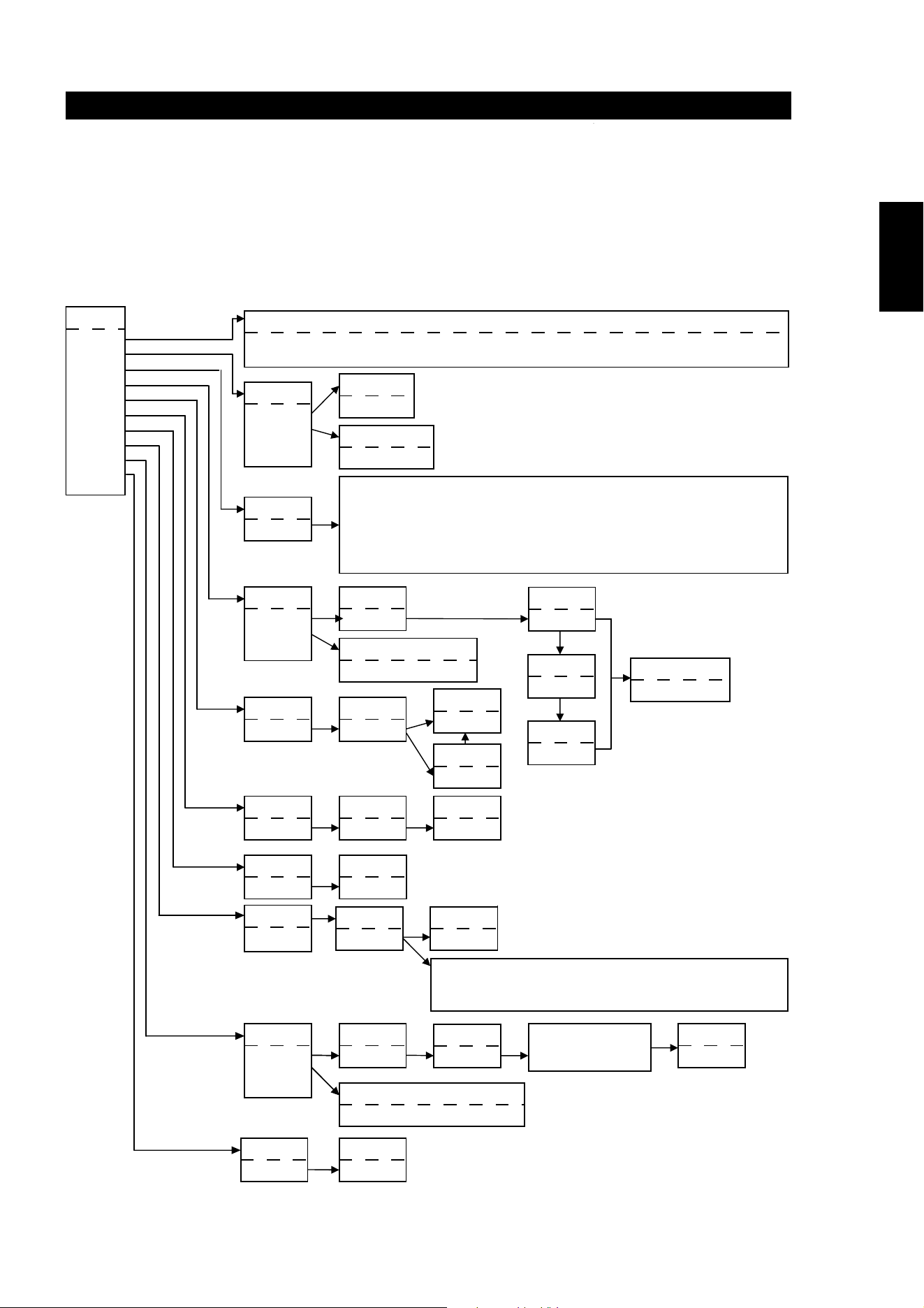
HTRM
–
Setup Menu
General Menu Operation:
•Press and hold SETUP+ ENTER for 5 seconds to enter setup menu.
•The MACRO key is a cancel function in all setup modes unless otherwise noted.
•You can exit menus by selecting Exit or pressing the MACRO key.
•Use Up and Down cursor keys to select different menu items. An Up/Down arrow will be shown on the display when this action is available.
•For options which can be changed, the Right and Left keys are used to cycle through the available options. Left and Right arrows will be
shown on the display to indicate when an option can be changed.
•Press ENTER to select a menu option or confirm a value.
<No/Yes>
Save?
P
Start…
{Device}
M
Learn…
{Device}
L
Release
{Device}
L
Pass 2..
{Device}
L
Success/Failed
{Device}
L
2-Pass Mode
2 Second Delay
Key?
Macro
P
From?
{Device}
C
To?
{Device}
C
<No/Yes>
Copy?
C
**WARNING! Sen Lvl is an adjustment that may lessen battery life. Refer to HTRM Special Features for adjustment.

18
ENGLISH FRANÇAIS
DEUTSCH
NEDERLANDS
ESPAÑOL
ITALIANO
PORTUGUÊS
SVENSKA
BACKLIGHT
The HTRM is equipped with a backlight to increase visibility of the HTRM in low light
conditions. The HTRM also includes a light sensor. By default, if you press any key on the
remote and it senses a low light condition, the back light will turn on. It will then turn off again
five seconds after no key has been pressed.
The behaviour and timeout for the backlight can be adjusted. (Refer to the “HTRM Features”
for further information.)
LOW BATTERY WARNING
If the HTRM senses the batteries are low, it will show "Low Batt" on the second line of the
LCD display whenever the remote is idle. When this occurs the batteries should be replaced
with new ones immediately.
DEVICE SELECTOR KEYS
Simply pressing a DEVICE SELECTOR key will change the active device on the HTRM. At this
time, no IR commands will be transmitted. The name of the selected device will be shown on
the first line of the LCD display.
Note: Any IR command can be associated with a DEVICE SELECTOR key during “Copy” and
“Learn” modes. Once the associated function is assigned to the DEVICE SELECTOR key
pressing and holding the DEVICE SELECTOR key for more than two seconds will send the
associated command in addition to the HTRM switching its active device.
NAVIGATION OF THE HTRM CONTROLS
MACRO KEYS
A macro can be associated with every key on the HTRM except for the MACRO button itself.
A total of 52 macros can be stored.
To execute a macro:
• Press the MACRO key. The first line of the LCD display will show "MACRO".
• Within five seconds, press the key the macro is associated with.
• While the macro is executing a small "M" will be shown in the top right of the LCD
display. (refer to the Setup Menu section for information on how to setup macros)
FUNCTION KEYS
There are 44 dedicated function keys on the HTRM. When you press a function key, the name
of the function will be shown on the second line of the LCD display while the command is
being transmitted.
A/V PSET KEY
In the default configuration of the HTRM, the A/V PSET key acts as a shift function when the
AMP device is selected. Pressing the A/V PSET key once will cause "Preset" to be displayed
on the first line of the LCD display. If within five seconds you then press a digit 0 - 9, the
function for the corresponding A/V Preset will be transmitted.
Note: The HTRM is an universal-type remote control, some NAD receivers may not have
more than 5 AV presets.
SETUP MENU
Press and hold the SETUP and ENTER keys for five seconds to enter the Setup Menu. You
cannot enter the setup menu if the remote is currently displaying "Low Batt". This feature
prevents the setup from becoming corrupted under low battery conditions.
Please refer to Setup Navigation for the overall structure and basic operation of the Setup
Menu.
ABOUT THE HTRM
Identification of controls

19
ENGLISH
FRANÇAISDEUTSCHNEDERLANDSESPAÑOL
ITALIANO
PORTUGUÊS
SVENSKA
ABOUT THE HTRM
Identification of controls
HTRM FEATURES:
BATTERY
Instead of waiting until the "Low Batt" warning is displayed, you can check the current
battery level using this option. This option will show a bar graph representing the current
battery level. When the batteries are new, the bar graph will show 8 bars, Once the bar graph
reaches close to zero, the "Low Batt" warning will start to show.
BACK LIGHT SENSITIVITY (B LIGHT)
The backlight timeout can be set from 0 - 20 seconds. This is the length of time the backlight
stays on after releasing the last key.
The following backlight modes are available:
• Off - The backlight will never come on.
• Sense - The backlight will only come on if the light sensor detects low light conditions.
• On - The backlight will come on any time a key is pressed.
• Sense Level - The point where the back light comes on in a darkened room
LIBRARY
This function allows you to set all the function keys for a device to the functions stored in the
included library tables.
LEARN
This function allows you to learn IR commands from another remote.
To learn a function into a DEVICE SELECTOR key press the desired DEVICE SELECTOR key
momentarily and then press and hold the same key for more than two seconds.
PUNCH THROUGH
There are two types of punch through functions.
The first type allows a function key to punch through to another device. For example, by
default, the volume keys for the DVD device punch through to AMP.
The second type allows you to punch through to a stored macro. This provides a way to
execute a macro with a single keys press.
If a macro step includes a key which has a punch through to another macro, the punch
through is not used. This is to prevent circular macros that would never end. Instead of the
punch through, the underlying function of the key will be used when the macro is executed.
This allows you set a single key press macro for a key without losing the original functionality
of that key. For example; you could record a macro which includes AMP power on, TV power
on and DVD power on and then have the AMP power on button activate this macro.

20
ENGLISH FRANÇAIS
DEUTSCH
NEDERLANDS
ESPAÑOL
ITALIANO
PORTUGUÊS
SVENSKA
COPY
This function allows you to copy functions from one key to another. If you want to select a
DEVICE SELECTOR key for either the "From?" or "To?" you must press and hold the key for
two seconds. Just pressing the key momentarily will only change the active device.
DELETE
Each key can have several functions types stored. However, only the highest priority type will
be active. When you delete a function, a lower priority function type may become active. To
completely erase the functionality of a key, you may need to execute the Delete function
multiple times.
For example; if you delete a learned command, a lower priority command may become active.
The order of priority for each function type are:
• Punch Through
• Learned
• Copied Library Command
• Default Library Command
To delete the function from a DEVICE SELECTOR key you must press and hold the key for
two seconds. Just pressing the key momentarily will only change the active device.
RENAME
All keys can be renamed except the MACRO key. In the RENAME menu, first press the
DEVICE SELECTOR key then the function key; the second line of the LCD will be blank ready
to accept the alpha-numeric characters. Use the navigation arrows to select the alpha-
numeric characters, and then press the ENTER key. Select “Save” and then “Yes” to store
the new name.
Note: There are a maximum of eight segments available for the alpha-numeric characters.
MACRO
While recording macros, the HTRM will function as normal except there will be a small "M"
in the top right of the LCD display, and IR commands are transmitted the same as during
normal operation.
Macros will be executed with the same timing as they were recorded. The length of time each
command is sent will also correspond to the length of time the key was held down for while
recording.
By default, when a macro is executed, the currently selected device will be returned to what
it was before the macro was executed. However, if the very last button pressed while
recording a macro is a DEVICE SELECTOR key, the device will be changed at the end of
executing the macro.
RESET
Selecting this option and answering "Yes" to both confirmations will reset all HTRM options
to the factory default values.
Note: resetting the HTRM to the factory default settings will erase all user configurations,
macros, and custom device programming.
ABOUT THE HTRM
Identification of controls
21
ENGLISH
FRANÇAISDEUTSCHNEDERLANDSESPAÑOL
ITALIANO
PORTUGUÊS
SVENSKA
ABOUT THE HTRM
Identification of controls
USB INTERFACE
The HTRM allows one to upload and download the configuration through a Windows PC and
NAD’s Proprietary HTRM programming software. See Figure 8 on how to connect an USB A
male to mini USB B male 5-pin cable to the HTRM.
NOTES: Please log onto www.nadelectronics.com for the latest HTRM interface control
software.
Use an USB A male to mini USB B male 5-pin cable between your Windows® PC and the
HTRM.
Your custom installer or dealer can assist you in the proper setup and configuration of the
mini USB interface and software.
The mini USB B male 5-pin cable is not supplied with the HTRM. Your custom installer or
dealer can assist you in the procurement of the USB A male to mini USB B male 5-pin cable.
Figure 8

22
ENGLISH FRANÇAIS
DEUTSCH
NEDERLANDS
ESPAÑOL
ITALIANO
PORTUGUÊS
SVENSKA
REAR PANEL CONNECTIONS AND CONTROLS
WARNING!
Make all connections to your M15 surround sound preamplifier with the unit powered off and
unplugged from the AC power. Furthermore, unplug all auxiliary components' AC power
before making or breaking any signal connections.
1. COMPONENT VIDEO IN (YUV): Connect inputs to component-video signal or wide-band
component video from a source component such as a DVD-player or HDTV satellite/cable
box. Be sure to observe consistency in connecting the Y, C
B
/P
B
, and C
R
/P
R
jacks to the
corresponding sources/inputs. COMPONENT VIDEO IN may be configured via the M15's
OSD menu.
2. S-VIDEO IN: Connect S-Video inputs DVD, SAT, VCR, VIDEO 4 through VIDEO 6 from
source components. Configuration of the S-Video inputs is through the M15's OSD menu.
3. S-VIDEO OUT: There are two S-Video record outputs, VCR and VIDEO 4. Connect to S-
Video record inputs of recording components.
4. COMPOSITE VIDEO IN (CVBS): Connect to composite video inputs DVD, SAT, VCR,
VIDEO 4 through VIDEO 6 to composite video from the source components.
Configuration of the video inputs is through the M15's OSD menu.
5. COMPOSITE VIDEO OUT (CVBS): There are two composite video record outputs, VCR
and VIDEO 4. Connect to composite-video record-inputs of recording components.
6. MONITOR OUT (video out): All video inputs (CVBS, S-Video, YUV) are available from
these outputs. You can connect either of these outputs to your monitor/HDTV. CVBS video
and S-Video inputs up-converts to YUV video out. Configuration of the MONITOR OUT
video is through the M15's OSD menu.
Note: The OSD is not available on the HDMI OUT output
Both S-Video and composite video inputs are format converted to both the Component
video outputs. Selection of the format is through the M15's OSD menu.
The DIRECT COMPONENT VIDEO OUT is a direct pass-through component video
signal without the M15's OSD.
NAD recommends that one connects the DIRECT COMPONENT VIDEO OUT YUV to
your monitor for NTSC (North American) video formats 480p/720p/1080i, and PAL
(European) video formats 576p/720p/1080i.
M15 VIDEO SWITCHING LOGIC
The M15 was optimized for Component Video (YUV) output. Composite (CVBS) and S-Video (SV) sources
may be viewed in their native format or via the Component Video (YUV) output.
Note: Monitor type selection is limited to a valid input signal type selected.
ABOUT THE M15
Identification of controls
Monitor Type Monitor Type Monitor Type
YUV Output S-Video Output CVBS Output
CVBS Input YES NO YES
S-Video Input YES YES NO
YUV Input YES NO NO
23
ENGLISH
FRANÇAISDEUTSCHNEDERLANDSESPAÑOL
ITALIANO
PORTUGUÊS
SVENSKA
7. HDMI IN/OUT: Connect inputs to the HDMI connector of the source component such
DVD-player or HDTV satellite/cable box. Connect the output to a HDTV or projector with
HDMI input. (See figure below)
Note: HDMI IN and OUT are direct pass-through signal without OSD.
8. COAXIAL IN/OUT: Connect COAXIAL IN to RCA coaxial sources such as CD, DVD-player,
or Cable/Satellite decoder. Connect the COAXIAL OUT to RCA coaxial input of a
recording component. Configuration of the COAXIAL IN and OUT association is through
the M15's OSD menu.
9. OPTICAL IN/OUT: Connect OPTICAL IN to optical S/PDIF-format digital sources such as
CD or DVD-players. Connect OPTICAL OUT to the optical S/PDIF digital input of a
recording component such as a CD recorder, DAT deck, or computer. Configuration of the
OPTICAL IN and OUT association is through the M15's OSD menu.
10. RS-232: Using a Windows® operating system personal computer, one can remotely
control the M15 with NAD's proprietary interface control software. This remote control
facility employs a functional image of the M15's front panel as the GUI (graphical user
interface). This connector is a standard DB-9 RS-232 configuration. Use an "off-the-shelf"
DB-9 RS-232 serial cable to connect between your Windows® PC's DB-9 RS-232
connector and the M15's RS-232 connector.
Notes: Please log onto www.nadelectronics.com for the latest M15 interface control
software.
Use a standard DB-9 male to DB-9 female RS-232 serial cable between your Windows®
PC and the M15.
Do not use a null-modem type of RS-232 cable.
Some Windows® PC's may not have RS-232 serial connector. In this event, use a
standard "off-the-shelf" RS-232 to USB adaptor to connect to your Windows® PC.
Follow the instructions that come with the RS-232 to USB adaptor for setting up the
adaptor.
Your custom installer or dealer can assist you in the proper setup and configuration of
the RS-232 interface.
Neither a DB-9 RS-232 serial cable nor a RS-232 to USB adaptor is supplied with the
M15.
ABOUT THE M15
Identification of controls
Rear of M15 AV Surround Sound Preamplifier
HDMI connectio n
HDMI Comp atible TV
1
1
2
3
2
13
24
4
COAXIAL IN
HDMI IN
1
2
1
2
HDMI OUT
OPTICAL IN OPTICAL OU T
COAXIAL
OUT
AUT O TRIGGE R
+12V TRIGGE R
ON
OF F
IN
VGA OUTPU T
HDMI OUT
Rear of M55 DVD Player
HDMI connectio n
SCART/RGB OUT
DB-9 Pin # Function
2 Transmit Data
3 Receive Data
5 Signal Ground
DB-9 pin-out Assignment
24
ENGLISH FRANÇAIS
DEUTSCH
NEDERLANDS
ESPAÑOL
ITALIANO
PORTUGUÊS
SVENSKA
11. CD, DISC, TUNER Inputs: Connect to stereo analog outputs of audio components.
12. TAPE IN/OUT: Connect TAPE OUT to the analog recording component’s stereo analog
inputs, and TAPE IN to the analog recording component’s stereo analog outputs. Suitable
components would be cassette deck, CD-recorder, or auxiliary analog audio processor.
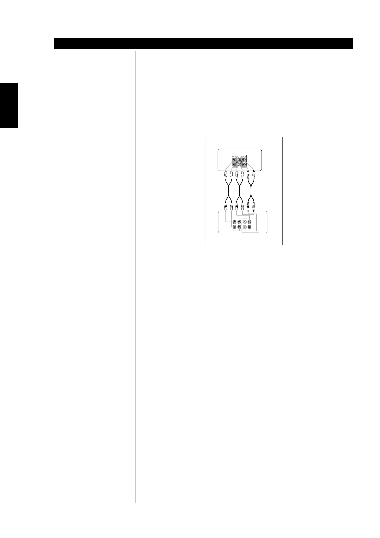
13. EXTERNAL 7.1 INPUTS: Connect to the corresponding analog audio outputs of a multi-
channel source component such as a DVD-Audio or multi-channel SACD player. There are
neither bass/treble controls nor other audio processing available for these inputs. (See
figure below).
14. IR IN/OUT: There are two 3.5mm IR OUT and one IR IN jacks. Connect to the
corresponding 3.5mm IR jacks (input to output and vice versa) of compatible infrared
receiver/transmitter components. Your custom installer or dealer can assist you in the
proper setup and configuration of the infrared cables and equipment interface.
15. +12 V TRIGGER OUT/IN: There are three configurable +12V trigger outputs. These +12V
TRIGGER OUT can follow the powered state of the M15. Use this 3.5mm mini-jack
connector to pass +12 volts at a maximum current of 50 milliamps to auxiliary equipment
such as a multichannel amplifier or subwoofer. Configuration of the trigger level and
duration for each output is through the M15's TRIGGER SETUP OSD menu.
The +12 V TRIGGER IN is setup in the TRIGGER SETUP OSD. When set to ON. a +12V
signal will turn on the M15 from standby.
Note: The centre conductor (hot) of the 3.5mm jack is the control signal. The outside
conductor (shield) is the ground return-path. Your custom installer or dealer can assist
you in the proper setup and configuration of the +12V TRIGGER OUT/IN interface and
cables.
ABOUT THE M15
Identification of controls
FRONT
L
R
SURR
L
R
SURR- B
L
EXTERNAL 7. 1 I NPUT
R
CENTER
SUBW
Rear of M15 A/V Surround Sound
Preamplifie r 7.1 OutInputs and Audio P re-
Rear of a DVD Player
5.1 Channel Output
5.1 CH OUTPUT
L
R
L
R
SUBW
FRONT
CENTER
SURR
25
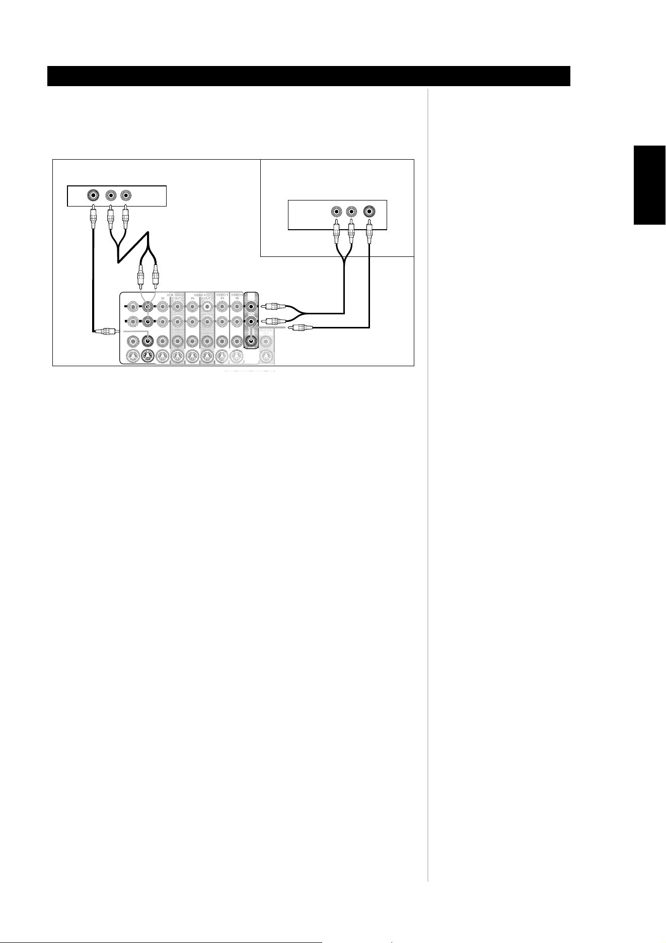
16. MS OUT (zone 2): Connect to the inputs of the stereo amplifier (an amplifier with or
without a volume control) for the second zone location. Connect COMPOSITE VIDEO
MS OUT and L/R audio to your zone AV Receiver. (See example below).
17. AUDIO PRE-OUT: Connect L (front left channel), R (front right channel), and C (center)
to the channel inputs of the power amplifiers driving the front channels. Connect RS (right
surround) and LS (left surround) to the power amplifier driving the surround speakers and
SBR (surround back right) and SBL (surround back left) to that driving the surround-back
speakers. Finally, connect SUB1/2 to the line input of a powered subwoofer or to the
amplifier driving a passive subwoofer. Configuration of the speaker level, size, and distance
is through the M15's OSD menu.
18. SWITCHED (Power Socket): Insert the power cable from auxiliary equipment that is to
turn on or off when the M15 is powered on or off using the POWER (vacation switch).
USING THE M15
Identification of controls
ENGLISH
FRANÇAISDEUTSCHNEDERLANDSESPAÑOL
ITALIANO
PORTUGUÊS
SVENSKA
Rear of M15 AV S urround Sound Preamplifier
SA T Input to ZONE 2/MS OUT
Rear of Satellite Receiver
Rear of AV Receiver in
another Room/Zone
DVD
IN
L
R
SA T
IN
VIDEO 5
IN
VIDEO 6
IN
IN
IN
OUT
OUT
VIDEO 4
MS
OUT
MONIT OR
OUT
VCR
COMPOSIT E
VIDE
O
OUT
YC/PBB C/PRR
S-VIDEO

26
19. IEC Power Cable Socket: Attach the M15's power cable to this IEC socket first, before
connecting the power cable to the AC-mains outlet. Never disconnect the power cable
from the IEC socket before disconnecting the power cable from the AC-mains outlet.
Failure to follow this procedure may result in a possible electric shock hazard. Always make
sure that the POWER switch is in the OFF position and disconnect the power cable from
the AC-mains outlet, before disconnecting or changing input connections on the back
panel. Failure to follow this procedure may result in possible damage to the either the M15
or other auxiliary equipment.
Note: When connecting or disconnecting audio cables from the back panel of the M15,
disconnect any auxiliary equipment from their AC-mains outlets as well. Failure to
follow this procedure may result in possible damage to the either the M15 or other
auxiliary equipment.
20. POWER switch: The POWER switch supplies the master AC mains power for the M15.
When this switch is in the ON position the M15 is in standby as shown by the amber Status
Condition L.E.D. above the standby switch on the front panel. If you intend not to use the
amplifier for long periods of time (such as when on vacation), switch the POWER switch
to the OFF position.
Note: When the POWER switch is in the OFF position, neither remote control ZR 2, HTR-
M, nor the front panel Power switch will activate the M15.
USING THE M15
Identification of controls
ENGLISH FRANÇAIS
DEUTSCH
NEDERLANDS
ESPAÑOL
ITALIANO
PORTUGUÊS
SVENSKA

27
OSD AND MONITOR OUTPUT
There are three outputs that contain the M15 OSD. These are MONITOR OUT CVBS, S-
Video, and YUV. There are two versions of OSD, SIMPLE and FULL. Each will be superimposed
over an existing video source.
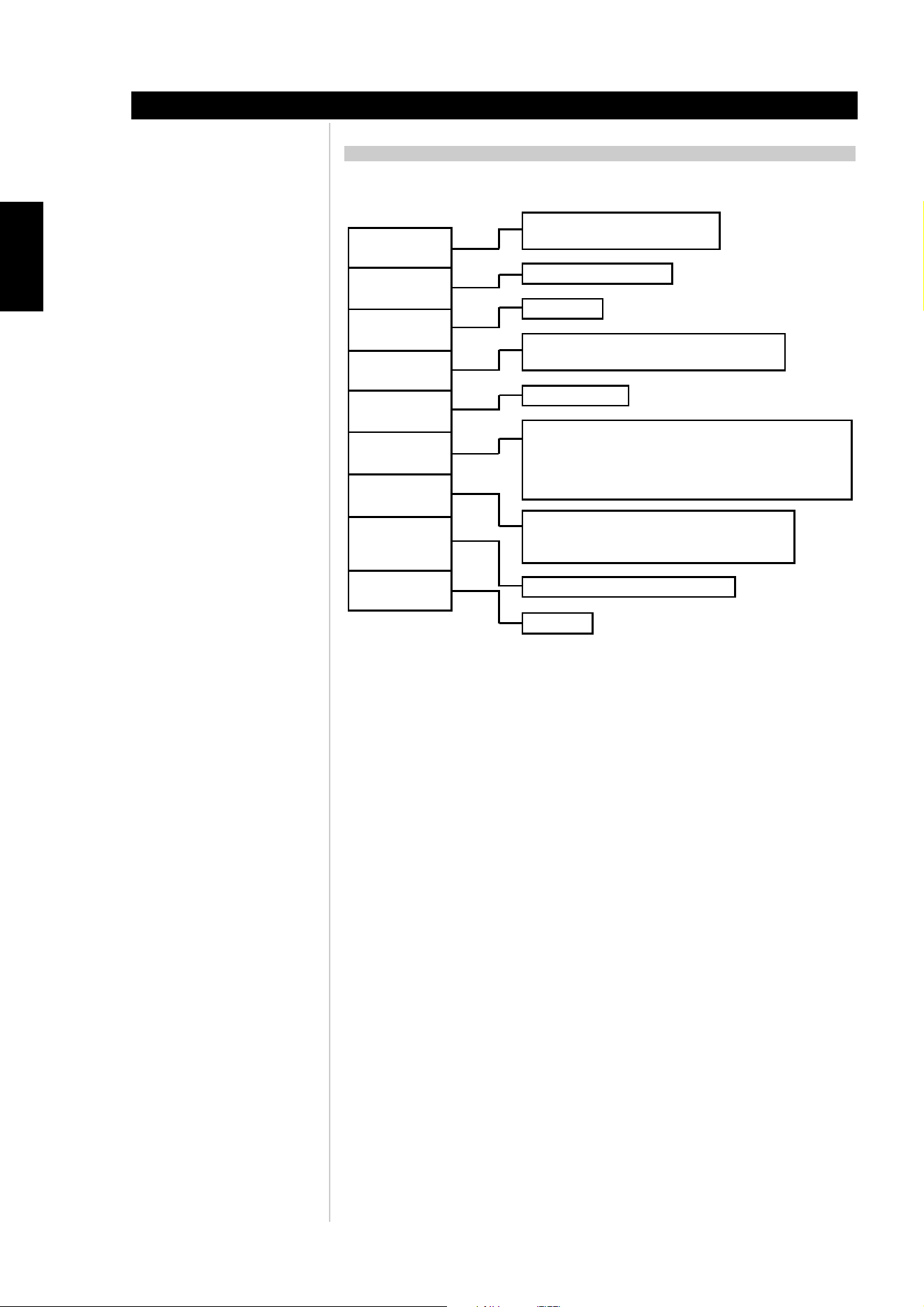
NAVIGATION OF THE ON SCREEN DISPLAY (OSD) MENUS
There are seven main On Screen Menus (OSD); Audio Control, THX/SPEAKER SETUP, SOURCE
SETUP, DISPLAY SETUP, TRIGGER SETUP, ZONE 2/MS Out, and A/V PRESETS. To enter the OSD,
press the HTRM’s ENTER. Use the and to select the submenu and press to
enter the submenu. Use the to back out of submenus and menu variables without
saving changes.
Notes: Some menu options feedback direct real-time responses not requiring one to press
the ENTER button to save the selection.
Some menu lines are titles that do not have variables in them.
AUDIO CONTROL
The Audio Control menu has nine submenus, BASS, TREBLE, CENTER DIALOG, TONE
CONTROLS, ENHANCED BASS, AUDIO DELAY, LFE LEVEL, THX AUTO, and then ENHANCED
STEREO submenus.
BASS, TREBLE, CENTER DIALOG, AND TONE CONTROLS ON/OFF
These three level controls are arbitrary. These controls allow one to tweak on-the-fly the
frequency response of the source during playback in the AUDIO CONTROL OSD menu in
conjunction with the HTRM’s TONE button and the navigation buttons. Maximum and
minimum values for BASS and TREBLE are +/- 10.0dB, for CENTER DIALOG they are +/- 6dB.
Notes: BASS, TREBLE and CENTER DIALOG are available for surround sound sources with
THX off.
Tone controls are not stored in memory, but are reset every time the M15 is switched to
standby.
Turning off the tone controls bypasses all tone controls filters.
Tone controls are available on the front left, right and center speakers.
LFE LEVEL AND ENHANCED BASS
LFE adjustment allows one to decrease the level of Low Frequency Effect encoding of digital
source materials. This helps in conjunction with the SPEAKER LEVEL adjustments which assists
the user in matching the A/V system. Maximum level is 0.0dB, minimum level is -10.0dB
relative to SPEAKER LEVEL adjustments.
Normally, with speakers set to LARGE the subwoofer is not active. The ENHANCED BASS
option allows full range operation of the speakers with the additional bass contribution of the
subwoofer. This feature is particularly useful when one wants to experience maximum bass
output. Please note that due to acoustic cancellation effects, the bass response may be uneven
when using this setting.
Note: The LFE and ENHANCED BASS options are part of the A/V Preset memories
AUDIO DELAY
When connecting the M15 to a DLP projector, there may be a delay in the picture relative to
the audio. In order to match this delay, the M15 allows up to 140ms of delay via 10ms
increments.
Note: The AUDIO DELAY is not stored in memory, but is reset to 0.0 every time the M15 is
switched to standby.
THX AUTO
Select THX AUTO to ON when the post process decoding is to be THX controlled. When THX
AUTO is set to ON then all Dolby and DTS decoding formats will automatically pass through
the THX decoder.
Note: THX Ultra 2 decoding is dependent on the speaker configuration
USING THE M15
setup
ENGLISH
FRANÇAISDEUTSCHNEDERLANDSESPAÑOL
ITALIANO
PORTUGUÊS
SVENSKA
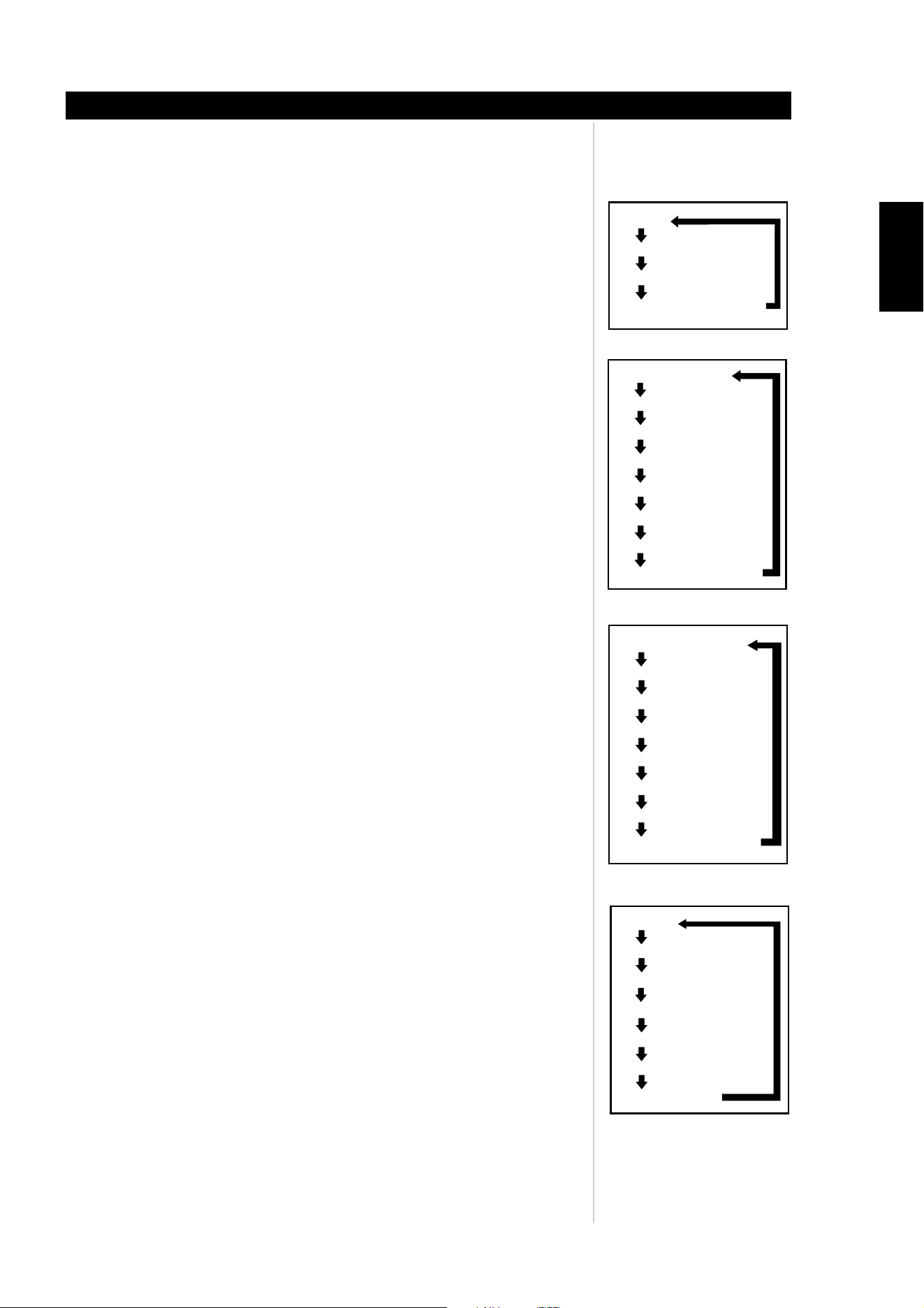
MAIN MENU
-> AUDIO CONTROL
-> THX/SPEAKER SETUP
-> SOURCE SETUP
-> DISPLAY SETUP
-> TRIGGER SETUP
-> ZONE 2/MS OUT
-> A/V PRESETS
-> (press > to advance)
-> (press < to exit)
AUDIO CONTROL
-> BASS 0.0dB
-> TREBLE 0.0dB
-> CENTER DIALOG 0.0dB
-> TONE CONTROLS ARE ON
-> AUDIO DELAY 0ms
-> LFE LEVEL 0.0dB
-> ENHANCED BASS OFF
-> THX AUTO ON
-> ->ENHANCED STEREO
AUDIO CONTROL
-> BASS 0.0dB
-> TREBLE 0.0dB
-> CENTER DIALOG 0.0dB
-> TONE CONTROLS ARE ON
-> AUDIO DELAY 0ms
-> LFE LEVEL 0.0dB
-> ENHANCED BASS OFF
-> THX AUTO ON
-> ->ENHANCED STEREO
AUDIO CONTROL
-> BASS 0.0dB
-> TREBLE 0.0dB
-> CENTER DIALOG 0.0dB
-> TONE CONTROLS ARE ON
-> AUDIO DELAY 0ms
-> LFE LEVEL 0.0dB
-> ENHANCED BASS OFF
-> THX AUTO ON
-> ->ENHANCED STEREO
AUDIO CONTROL
-> BASS 0.0dB
-> TREBLE 0.0dB
-> CENTER DIALOG 0.0dB
-> TONE CONTROLS ARE ON
-> AUDIO DELAY 10ms
-> LFE LEVEL 0.0dB
-> ENHANCED BASS OFF
-> THX AUTO ON
-> ->ENHANCED STEREO
AUDIO CONTROL
-> BASS 0.0dB
-> TREBLE 0.0dB
-> CENTER DIALOG 0.0dB
-> TONE CONTROLS ARE ON
-> AUDIO DELAY 0ms
-> LFE LEVEL 0.0dB
-> ENHANCED BASS OFF
-> THX AUTO ON
-> ->ENHANCED STEREO

28
THX/SPEAKER SETUP
THX/SPEAKER SYSTEM
The following are your speaker selection options for the speaker size and filters. Press ENTER
on the HTRM to save the speaker settings:
• FRONT L+R; SMALL (THX) or LARGE
• CENTER; SMALL (THX), LARGE, or NONE.
• SURROUND; 1 SMALL LEFT (mono left channel out), 2 SMALL (THX), 1 LARGE LEFT
(mono left channel out), 2 LARGE, or NONE.
• SURR BACK (Surround Back); 1 SMALL LEFT (mono left channel out), 2 SMALL (THX), 1
LARGE LEFT (mono left channel out), 2 LARGE, or NONE.
• SUBWOOFER; 1,1 SMALL (THX), 2, 2 SMALL (THX), or NONE.
• LR + LFE XOVER (Front Left and Right channel and the LFE); 60Hz, 70Hz, THX 80Hz,
90Hz, 100Hz, 110Hz, 120Hz
• CENTER XOVER; 60Hz, 70Hz, THX 80Hz, 90Hz, 100Hz, 110Hz, 120Hz
• SURR XOVER (Surround Channels Crossover frequency); 60Hz, 70Hz, THX 80Hz, 90Hz,
100Hz, 110Hz, 120Hz
• BASS FILTER (Crossover Frequency Slope); THX or 2ND ORDER
SPEAKER LEVEL
All speaker levels are adjustable from -12dB to +12dB. Press ENTER on the HTRM to save the
level settings
SPEAKER DISTANCE
All speaker distances from the central listening point are adjustable from 0ft to 22ft (0m to
6.7m). Press ENTER on the HTRM to save the distance settings.
The speaker distance will be shown in either units feet or metres.
Note: If inappropriate speaker delays are set, a warning will display indicating too much
time offset between Left and Right channels. The following warring will display;
“** error! L/R delay > 2ms”
THX ULTRA2
Set the subwoofer BOUNDARY GAIN COMPENSATION to ON or OFF depending on
whether you have one or two THX ULTRA2 subwoofers in close proximity to vertical surfaces.
If a listener is sitting too close to a vertical surface their perception of the low frequencies is
perceived as exaggerated. However, with The Boundary Gain Compensation filter applied to
all output channels, the bass is equalized resulting in a flatter, more accurate bass response.
Press ENTER on the HTRM to save the boundary gain settings.
Note: Boundary Gain Compensation is only available for THX ULTRA2 subwoofer
selections.
DISTANCE BETWEEN SBL+SBR SPEAKERS
When you select two surround back speakers, set the distance between the two speakers in
between 0ft to 22ft (0m to 6.7m). This setting will give correct spacial effect of the rear
channels during THX Cinema, THX Surround EX, THX Music, and THX ULTRA2 decoding.
Press ENTER on the HTRM to save the distance settings.
USING THE M15
Setup
ENGLISH FRANÇAIS
DEUTSCH
NEDERLANDS
ESPAÑOL
ITALIANO
PORTUGUÊS
SVENSKA
MAIN MENU
-> AUDIO CONTROL
-> THX/SPEAKER SETUP
-> SOURCE SETUP
-> DISPLAY SETUP
-> TRIGGER SETUP
-> ZONE 2/MS OUT
-> A/V PRESETS
-> (press > to advance)
-> (press < to exit)
THX/SPEAKER SYSTEM
-> FRONT L+R SMALL (THX)
-> CENTER SMALL (THX)
-> SURROUND 2 SMALL (THX)
-> SURR BACK 2 SMALL (THX)
-> SUBWOOFER 1 THX ULTRA2
-> LR+LFE XOVER THX 80Hz
-> CENTER XOVER THX 80Hz
-> SURR XOVER THX 80Hz
-> BASS FILTER THX
-> ->NEXT (LEVEL)
SPEAKER LEVEL
-> FRONT LEFT 0.0dB
-> CENTER 0.0dB
-> FRONT RIGHT 0.0dB
-> SURR RIGHT 0.0dB
-> SURR BACK RIGHT 0.0dB
-> SURR BACK LEFT 0.0dB
-> SURR LEFT 0.0dB
-> SUBWOOFER 0.0dB
-> (for tone press TEST)
-> ->NEXT (DISTANCE)
SPEAKER DISTANCE
-> FRONT LEFT 10ft
-> CENTER 10ft
-> FRONT RIGHT 10ft
-> SURR RIGHT 10ft
-> SURR BACK RIGHT 10ft
-> SURR BACK LEFT 10ft
-> SURR LEFT 10ft
-> SUBWOOFER 10ft
-> DISTANCE UNITS FT
-> ->NEXT (THX ULTRA2)
THX ULTRA2
-> BOUNDARY GAIN ON
-> ->COMPENSATION
->
-> DISTANCE BETWEEN 6ft
-> ->->SBL+SBR SPEAKERS
THX ULTRA2
-> BOUNDARY GAIN ON
-> ->COMPENSATION
->
-> DISTANCE BETWEEN 6ft
-> ->->SBL+SBR SPEAKERS
29
THX BASS MANAGEMENT
For THX bass management to function, the speaker settings under THX SPEAKER SYSTEM
must be set to THX values as per the indication of “THX” for each setting. If all settings are
set to THX defaults, then THX and THX Ultra 2 will be available for THX bass management.
THX GUIDELINES
When receiving a 5.1 Dolby stream and using the THX AUTO select mode from the AUDIO
CONTROL OSD, then the following options are available:
7.1 SPEAKER SYSTEM
For 5.1 Dolby Digital stream with THX AUTO set to OFF; The M15 will allow Ultra2 Cinema
mode.
For 5.1 Dolby Digital stream with THX AUTO set to ON; The M15 will allow THX Surround EX
mode.
6.1 SPEAKER SYSTEM
For 5.1 Dolby Digital stream with THX AUTO set to OFF; The M15 will allow THX Cinema
mode.
For 5.1 Dolby Digital stream with THX AUTO set to ON; The M15 will allow THX Surround EX
mode.
5.1 SPEAKER SYSTEM
For 5.1 Dolby Digital stream with THX AUTO set to OFF; The M15 will allow THX Cinema
mode.
For 5.1 Dolby Digital stream with THX AUTO set to ON; The M15 will allow THX Cinema
mode.
Note: the THX/RES button on the HTRM may be used to temporarily enable or disable the
THX decoding format
USING THE M15
Setup
ENGLISH
FRANÇAISDEUTSCHNEDERLANDSESPAÑOL
ITALIANO
PORTUGUÊS
SVENSKA

30
SOURCE SETUP
INPUT LABEL (SOURCE SELECTION)
To edit the source selection and assignments of audio, video, and user delineable names, first
select the input and then press ENTER on the HTRM. You will note that the M15 will
automatically switch to this source allowing you real-time monitoring of the setup. All inputs
are configurable in the SOURCE SETUP other than ext 7.1 and tape monitor
Note: Assign the ext 7.1 and tape monitor to any video input selection by first selecting
the video input from DVD through to VIDEO 6, and then select the ext 7.1 or tape
monitor input from the M15's front panel (7.1 IN or TAPE 0 on the HTRM remote
control).
RENAME
You may assign a new label to the source inputs. This label will be shown in the VFD as well
as the temporary OSD. There are 8 locations for the available for the following characters;
A-Z, a-z, [,,], ->, <-, -, 0-9, :, ;,<, >, and, ?,
DIGITAL INPUT
The digital assignments available are the same that one can assign via the front panel, but in
this OSD, the assignments are locked in memory;
NONE, COAXIAL 1, COAXIAL 2, COAXIAL 3, COAXIAL 4, OPT 1, OPT 2, OPT 3 and OPT 4.
DEFAULT DIGITAL INPUT ASSIGNMENTS
DVD COAXIAL 1
SAT COAXIAL 2
VCR COAXIAL 3
VIDEO 4 COAXIAL 4
VIDEO 5 OPT 1
VIDEO 6 OPT 2
CD OPT 3
DISC OPT 4
Note: Set DIGITAL INPUT to NONE in the SOURCE SETUP menu for each analog input
source connection.
ANALOG SENS (ANALOG GAIN SETTING)
Analog sensitivity gain settings can be fixed or variable;
0dB, -3dB, -6dB, or AUTO. Generally, for most situations, AUTO is the best setting.
VIDEO TYPE
There are two video types that may be assigned to the A/V sources, CVBS and S-Video. These
video types will be format converted to YUV for MONITOR OUT. There are two high
definition video options assignable to each input, YUV and HDMI For YUV output, the M15
will automatically format convert the CVBS and S-Video to YUV.
Note: The inputs TUNER, DISC, CD, tape monitor and ext. 7.1 cannot be assigned S-
Video nor CVBS video.
For optimal video performance, THX recommends bypassing video conversion
(Composite Video in to Composite Video out, S-Video In to S-Video Out, Component
Video In to Component Video Out).
USING THE M15
Setup
ENGLISH FRANÇAIS
DEUTSCH
NEDERLANDS
ESPAÑOL
ITALIANO
PORTUGUÊS
SVENSKA
SOURCE SETUP
-> INPUT LABEL DVD
-> RENAME DVD
-> DIGITAL INPUT COAX 1
-> ANALOG SENS AUTO
-> VIDEO TYPE CVBS
-> COMPONENT VID CV 1
-> HDMI INPUT NONE
-> SOURCE ENABLED YES
SOURCE SETUP
-> INPUT LABEL DVD
-> RENAME M55 SACD
-> DIGITAL INPUT NONE
-> ANALOG SENS AUTO
-> VIDEO TYPE CVBS
-> COMPONENT VID NONE
-> HDMI INPUT HDMI 1
-> SOURCE ENABLED YES
SOURCE SETUP
-> INPUT LABEL DVD
-> RENAME DVD
-> DIGITAL INPUT COAX 1
-> ANALOG SENS AUTO
-> VIDEO TYPE CVBS
-> COMPONENT VID CV 1
-> HDMI INPUT NONE
-> SOURCE ENABLED YES
SOURCE SETUP
-> INPUT LABEL DVD
-> RENAME M15 SACD
-> DIGITAL INPUT NONE
-> ANALOG SENS AUTO
-> VIDEO TYPE CVBS
-> COMPONENT VID NONE
-> HDMI INPUT HDMI 1
-> SOURCE ENABLED YES

31
COMPONENT VID (VIDEO SELECTION)
There are two YUV component outputs. The MONITOR OUT YUV includes the OSD. The
DIRECT MONITOR OUT has no OSD. NAD recommends that one connects the DIRECT
MONITOR OUT YUV to your monitor for NTSC (North American) video formats
480p/720p/1080i, and PAL (European) video formats 576p/720p/1080i.
Note: MONITOR OUT YUV which includes OSD, displays OSD when the input signal is
NTSC video format 480i and PAL video format 576i.
Component video may be assigned to any of your sources. Options are NONE, CV-1, CV-2,
and CV-3. These video inputs override VIDEO TYPE inputs. Thus select this input only if CVBS
or S-Video are not to be used.
HDMI INPUT (DIGITAL VIDEO SELECTION)
HDMI video may be assigned to any of your sources. Options are NONE, HDMI-1, and HDMI-
2. HDMI video may be assigned to any of your sources. These video inputs are available in
parallel of VIDEO TYPE and COMPONENT VIDEO inputs. Thus select this input only if HDMI
is to be used. as both source and monitor.
Note: HDMI OUT does not include the M15’s OSD. HDMI OUT is always active when a
source has assigned HDMI-1 or HDMI-2. See Quick Start figure 3 for monitor
connection.
SOURCE ENABLED
One can enable/disable an unused input via this option. This is particularly useful if only a few
inputs are used and one selects the inputs from the front panel controls, bypassing unused
inputs.
Note: The HTRM will always give you direct access to any input even though it may have
been disabled in the SETUP OSD.
USING THE M15
Setup
ENGLISH
FRANÇAISDEUTSCHNEDERLANDSESPAÑOL
ITALIANO
PORTUGUÊS
SVENSKA
SOURCE SETUP
-> INPUT LABEL DVD
-> RENAME DVD
-> DIGITAL INPUT COAX 1
-> ANALOG SENS AUTO
-> VIDEO TYPE CVBS
-> COMPONENT VID CV 1
-> HDMI INPUT NONE
-> SOURCE ENABLED YES
SOURCE SETUP
-> INPUT LABEL DVD
-> RENAME M55 SACD
-> DIGITAL INPUT NONE
-> ANALOG SENS AUTO
-> VIDEO TYPE CVBS
-> COMPONENT VID NONE
-> HDMI INPUT HDMI 1
-> SOURCE ENABLED YES
SOURCE SETUP
-> INPUT LABEL DVD
-> RENAME M55 SACD
-> DIGITAL INPUT COAX 1
-> ANALOG SENS AUTO
-> VIDEO TYPE CVBS
-> COMPONENT VID NONE
-> HDMI INPUT HDMI 1
-> SOURCE ENABLED YES

32
DISPLAY SETUP
TV SYSTEM
Select between NTSC and PAL systems. Select NTSC (North American) or PAL (European) TV System in
order to view the OSD on your monitor. This setting only affects the OSD, the source material will be
displayed in its native format.
MONITOR TYPE
This setting sets the MONITOR OUT of the M15. Select between YUV, S-Video and CVBS. For source
inputs using both S-Video and CVBS, only YUV is available.
SUPERIMPOSE
You may superimpose the Setup OSD over any existing video by selecting ON. The OFF setting places the
OSD over a black background.
TEMP DISPLAY (TEMPORARY OSD)
One may display the operating state of the M15 temporarily by setting this variable to FULL. Otherwise
when the variable is set to SIMPLE only the volume OSD will display. A setting of OFF will disable the
temporary OSD.
Note: To display a temporary OSD on the MS OUT COMPOSITE VIDEO, the TEMP DISPLAY may be
set to either SIMPLE or FULL.
TRIGGER SETUP
TRIGGER 1 & TRIGGER 2+3
There are two trigger assignments, Trigger 1 and Trigger 2+3. The trigger outputs can be assigned to;
POWER ON, ZONE 2, DVD, SAT, VCR, Video 4, Video 5, Video 6, Disc, CD, and Tuner.
POLARITY
One may assign the steady-state of the trigger polarity to either POLARITY variables HIGH or LOW. This
steady-state polarity is the ‘active’ final state of the trigger output signal.
DELAY (S)
The delay between when one selects the assignment either from the front panel or HTRM remote, to
when the trigger signal will transition. The values are in seconds, set from 0, 1, or 5 seconds.
DURATION (S)
The duration of the steady state may be set in seconds from 1, 5, 10, 30, to INFINITE.
TRIGGER INPUT
when the TRIGGER INPUT is set to ON, the M15 will turn on from the standby state when a DC +12V
signal is present at the TRIGGER IN socket. As long as the signal is present the M15 will remain in the
ON state. When the +12V signal is absent, the M15 will revert to its standby state.
Note: The front panel button or the HTRM remote control can override the TRIGGER IN signal
ZONE 2/MS OUT
INPUT
Using the HTRM remote, select an input to display on the ZONE 2/MS OUT via this OSD menu. All inputs
other than tape monitor and ext. 7.1 can be selected at the ZONE 2/MS OUT using your HTRM remote
control in the main zone.
VOLUME
This volume setting is the temporary volume setting of the ZONE 2/MS OUT via HTRM remote control.
Adjust the level using the HTRM’s navigation arrows or from mute to +12 dB.
VOL DEFAULT (START UP ZONE 2 VOLUME)
This volume setting is the default volume setting from standby. The level may be set from mute to +12
dB using the same navigation arrows above. To store the value one must press the HTRM’s ENTER button.
USING THE M15
Setup
ENGLISH FRANÇAIS
DEUTSCH
NEDERLANDS
ESPAÑOL
ITALIANO
PORTUGUÊS
SVENSKA
DISPLAY SETUP
-> TV SYSTEM NTSC
-> MONITOR TYPE YUV
-> SUPERIMPOSE ON
-> TEMP DISPLAY FULL
ZONE 2
-> INPUT SAT
-> VOLUME -20.0dB
-> VOL DEFAULT -20.0dB
DISPLAY SETUP
-> TV SYSTEM PAL
-> MONITOR TYPE YUV
-> SUPERIMPOSE ON
-> TEMP DISPLAY SIMPLE
ZONE 2
-> INPUT SAT
-> VOLUME -12.0dB
-> VOL DEFAULT -20.0dB
TRIGGER SETUP
-> TRIGGER 1
-> ASSIGNED TO POWER ON
-> POLARITY HIGH
-> DELAY (S) 0
-> DURATION (S) INFINITE
-> TRIGGER INPUT ON
-> ->TRIGGER 2+3
TRIGGER SETUP
-> TRIGGER 2+3
-> ASSIGNED TO ZONE 2
-> POLARITY HIGH
-> DELAY (S) 1
-> DURATION (S) INFINITE

33
ENHANCED STEREO
ENHANCED STEREO is useful when maximum audio levels are required from all channels. The
default for ENHANCED STEREO is with all speakers set to ON. The stereo image may be
redirected to any set or all of the speakers.
For example, it is possible to redirect the stereo image from front to surround or rear speakers
through the setup OSD:
• Press ENTER on the HTRM remote, select AUDIO SETUP, and then scroll to ENHANCED
STEREO.
• Press the right navigation arrow to advance to the next menu.
• Scroll to the set of speakers you want ON or OFF, then press the navigation arrow
to enter the line item to edit.
• Then select ON or OFF using the navigation arrows , and then ENTER on the
HTRM remote.
A/V PRESETS
There are five A/V Presets permanently stored in the M15’s memory. As default, access to the
presets is via the number keys 1 through Preset 5. Using the HTRM remote control press the
A/V PSET button and then the number buttons 1 through 5; the OSD will indicate the preset
number chosen.
SETTING UP AUDIO/VIDEO PRESETS
A/V Presets are stored automatically as one enters each variable change in the M15's OSD.
These variables are;
• THX/SPEAKER SYSTEM (the number of speakers)
• SPEAKER LEVEL (the level of all speakers relative to the listener)
• SPEAKER DISTANCE (the distance of all speakers relative to the listener)
• THX ULTRA 2 settings
• ENHANCED BASS (large speakers receive full bass response with subwoofer on)
• LFE LEVEL (attenuation setting)
To program an A/V Preset, select on the HTRM A/VPSET and then the number 1 through to
5. Then enter the M15's OSD menu by pressing the HTRM's ENTER button. Once in the M15’s
OSD change the variables as mentioned above.
Note: Not all OSD variables that are stored by pressing the HTRM's ENTER button are part
of the A/V Preset, only those mentioned above.
A/V Preset 1 is the default preset for any source input not assigned to an A/V Preset.
THX/SPEAKER SYSTEM
-> FRONT L+R SMALL (THX)
CENTER SMALL (THX)
USING THE M15
Setup
ENGLISH
FRANÇAISDEUTSCHNEDERLANDSESPAÑOL
ITALIANO
PORTUGUÊS
SVENSKA
ENHANCED STEREO
-> FRONT L+R OFF
-> SURR L+R ON
-> SURR BL+BR OFF
-> CENTER OFF
-> SUB OFF
AUDIO CONTROL
-> BASS 0.0dB
-> TREBLE 0.0dB
-> CENTER DIALOG 0.0dB
-> TONE CONTROLS ARE ON
-> AUDIO DELAY 0ms
-> LFE LEVEL 0.0dB
-> ENHANCED BASS OFF
-> THX AUTO ON
-> ->ENHANCED STEREO
SPEAKER LEVEL
-> FRONT LEFT 0.0dB
SPEAKER DISTANCE
-> FRONT LEFT 10ft
f
THX ULTRA2
-> BOUNDARY GAIN ON
-> ->COMPENSATION
>
-> LFE LEVEL 0.0dB
-> ENHANCED BASS OFF
-> LFE LEVEL 0.0dB
-> ENHANCED BASS OFF
34
ASSIGNING A/V PRESETS
Link each A/V Preset to a source input to make it easy for you to select the A/V Preset simply
by the press of an HTRM's source input. The following is the procedure for assigning A/V
Presets to a source input:
• Press ENTER from the HTRM remote control, then using the buttons select A/V
PRESETS, and then press the button to enter the A/V PRESETS OSD
• Once in the A/V PRESETS OSD, select the A/V Preset you would like to assign by pressing
A/V PSET and the number on the HTRM remote control. The menu item "CURRENT
PRESET #" will show you the A/V Preset you have selected.
• Using the buttons, navigate to the “PRESET #” you want to assign and then
press the to enter the variable window. Press the navigation buttons to
scroll through the M15’s source input and then press the ENTER button. Continue this
process to assign each preset a source input as per you're A/V system requirements.
COPYING A/V PRESETS
During the naming of any A/V Preset, one may copy an existing A/V PRESET to another. This
is particularly useful when setting up the A/V system for the first time so that one does not
need to setup all speakers' settings for each assignment.
• Press ENTER from the HTRM remote control, then using the buttons select A/V
PRESETS, and then press the button to enter the A/V PRESETS OSD
• Either press A/PSET and then the number 1 through 5 on the HTRM, or navigate to the
CURRENT PRESET # and using the HTRM's navigation arrows select the A/V
preset. Press ENTER from the HTRM remote control.
• From the HTRM, navigate to the "COPY TO PRESET #" and then press . Then
using the HTRM's arrows select the target A/V Preset number. Press ENTER from
the HTRM remote control.
Notes: The user's calibrated A/V system is always A/V PRESET 1.
The M15 will remember the last selected source-assigned AV Preset, even when
powered OFF from the rear POWER switch.
A/V Preset 1 is the default preset for any source input not assigned to an A/V Preset.
To restore factory default A/V Preset settings; from the M15's front panel simultaneously
press audio and digital for North American defaults, or press video and digital for
European defaults, and then follow the instructions on the VFD in either case.
USING THE M15
Setup
ENGLISH FRANÇAIS
DEUTSCH
NEDERLANDS
ESPAÑOL
ITALIANO
PORTUGUÊS
SVENSKA
A/V PRESETS
LINK TO:
-> PRESET 1 DVD
-> [DEFAULT]
-> PRESET 2 NONE
-> PRESET 3 NONE
-> PRESET 4 NONE
-> PRESET 5 NONE
-> CURRENT PRESET 1
-> COPY TO PRESET 1
A/V PRESETS
LINK TO:
-> PRESET 1 DVD
-> [DEFAULT]
-> PRESET 2 VCR
-> PRESET 3 SAT
-> PRESET 4 CD
-> PRESET 5 NONE
-> CURRENT PRESET 1
-> COPY TO PRESET 1
A/V PRESETS
LINK TO:
-> PRESET 1 DVD
-> [DEFAULT]
-> PRESET 2 VCR
-> PRESET 3 SAT
-> PRESET 4 CD
-> PRESET 5 NONE
-> CURRENT PRESET 1
-> COPY TO PRESET 2

NO OSD
OSD IS SCROLLING
OSD AND VIDEO IS DISTORTED OR BLANKING
• Source video type is not 480i or 576i
• Monitor/TV is connected COMPONENT VIDEO
DIRECT
• M15 is connected to HDMI OUT
• Set the video source such as DVD-player to 480i
(NTSC) or 576i (PAL)
• Connect the Monitor/TV to COMPONENT
VIDEO MONITOR OUT.
• Use COMPONENT VIDEO MONITOR OUT to
view OSD
35
FACTORY DEFAULT SETTINGS
In the event that the M15 may become configured inappropriately or become non-responsive the factory default settings can be
set by the front panel buttons as follows;
• To set the factory default settings for the 120V version, simultaneously press the M15’s front panel buttons audio and digital.
• To set the factory default settings for the 230V version, simultaneously press the M15’s front panel buttons video and digital.
Note: Setting the M15 to factory default settings will erase any stored AV Presets and source input renaming.
HTRM SPECIAL FUNCTIONS
SOFTWARE VERSION NUMBER
• Press simultaneously the ON + TEST buttons for five seconds to display version numbers.
LIGHT SENSOR CALIBRATION MODE
• Press simultaneously the ENTER + SETUP buttons for five seconds to enter the setup menu. Then scroll down to “B Light”,
press ENTER, then scroll down to “Sens LvL” and press ENTER, you are now in the light sensor calibration mode:
• You will see displayed on the first line of the LCD where #### is the reading (0 - 1023) from the light sensor. The second line
shows a bar graph representing the reading.
• Press the ENTER key to exit this mode. A confirmation will be displayed. Select "Yes" or “No” to set the new value.
TROUBLESHOOTING
Reference
ENGLISH
FRANÇAISDEUTSCHNEDERLANDSESPAÑOL
ITALIANO
PORTUGUÊS
SVENSKA
CONDITION POSSIBLE CAUSE(S) POSSIBLE SOLUTIONS(S)
NO SOUND FROM ALL CHANNELS
NO SOUND FROM ZONE 2 OUTPUT
• AC power unplugged
• power not switched on
• outlet is un-powered
• Tape Monitor is engaged
• A digital input was selected for analog source
connection
• Check AC cable, connection, and outlet
• Disengage Tape Monitor
• Set DIGITAL INPUT to NONE in the SOURCE SETUP
menu for each analog input source connection.
NO SOUND FROM SOME CHANNELS • Faulty/missing cables
• THX/SPEAKER SETUP channel(s) set to “NONE”
• Power-amp or speaker-connections faulty
• Check cables
• Check THX/SPEAKER SETUP menu
• Check power amp, cabling, and speakers
NO SOUND FROM SURROUND CHANNELS • No surround listening mode is engaged
• surround-channels set to “NONE” on
THX/SPEAKER SETUP menu
• Surround-channels level set too low on SPEAKER
LEVEL menu
• Select appropriate listening mode
• Correct THX/SPEAKER SETUP or SPEAKER LEVEL
settings
NO SOUND FROM SUBWOOFER • Subwoofer is off, unpowered, or improperly
connected
• Subwoofer set to “NONE” on THX/SPEAKER
SETUP menu
• Subwoofer level set too low on THX/SPEAKER
SETUP menu
• Power-up subwoofer, check sub’s AC outlet or
check connections
• Correct THX/SPEAKER SETUP or LEVEL SETUP
settings
NO SOUND FROM CENTER CHANNEL • Source is a 2/0 (etc.) Dolby Digital or DTS
recording without center channel
• Center set to NONE on THX/SPEAKER SETUP
menu
• Center level set too low on THX/SPEAKER SETUP
MENU
• Play a known 5.1-channel recording or select
Dolby Pro Logic or Mono mode
• Correct THX/SPEAKER SETUP or LEVEL SETUP
settings
NO DOLBY DIGITAL/DTS • Source’s digital output is not connected to an
M15’s digital input
• Check connections
M15 DOES NOT RESPOND TO HTRM REMOTE
OR ZR2 REMOTE
• Batteries are flat or incorrectly inserted
• IR transmitter window on remote, or IR receiver
window on M15 is obstructed
• M15 front panel is in very bright sunlight or
ambient light
• Check batteries
• check IR windows and ensure clear line-of-sight
from remote to M15
• reduce sunlight/room lighting
GREY OR BLANK PICTURE • Source video type is not set correctly in the
SOURCE SETUP menu.
• Video monitor is not set correctly in the DISPLAY
SETUP menu
• Set the video type as per the video chart on page
22 for each source in the SOURCE SETUP menu.
Component Video YUV overrides the VIDEO
TYPE settings of S-Video and CVBS
• Set the video MONITOR TYPE as per the video
chart on page 22 in the DISPLAY SETUP menu.
For multiple source VIDEO TYPE configurations,
set MONITOR TYPE to YUV

36
ENGLISH FRANÇAIS
DEUTSCH
NEDERLANDS
ESPAÑOL
ITALIANO
PORTUGUÊS
SVENSKA
SPECIFICATIONS
Reference
DECODING FORMATS
Dolby Digital, Dolby Digital EX, Dolby Pro Logic II, Dolby Pro Logic IIx, DTS, DTS ES, DTS Neo:6,
DTS 96/24, THX Surround EX, THX Ultra 2
SAMPLING RATES
32kHz, 44.1kHz, 48kHz, 88.2k, 96kHz
MODES
EARS, Enhanced stereo, Mono
VIDEO
Input and output impedance 75:
THD + NOISE
0.002%
PRE-AMP SECTION
LINE LEVEL INPUTS
Input impedance (R+C) 56k:/180pF
Frequency response (20Hz to 20kHz) 20Hz to 20kHz @ +/-0.3dB
LINE LEVEL OUTPUTS
Output impedance 470:
Tape Source Z + 2k:
Signal/noise ratio >102dB
Maximum Output Level. 6Vrms
Multiroom Output (Zone 2) 470:
TONE CONTROLS
Bass ±10dB@20Hz
Treble ±10dB@20kHz
Center Dialog ±6dB@1kHz
+12VOLT TRIGGER OUT
Output Voltage +12V +/- 20%
Minimum Output Current >40ma
Maximum Short Circuit Current <60mA
PHYSICAL SPECIFICATIONS
Operating temperature: 5 °C to 35 °C (41 °F to 95 °F)
Operating humidity: 5 % to 90 %
Dimensions (W x H x D) Net 17.13 x 5.24 x 13.98"(435 x 133 x 355mm)
Gross* 17.13 x 5.79 x 14.96”(435 x 147 x 380mm)
Net Weight 15 lbs
Shipping Weight 20 lbs
*Gross dimensions include feet, volume knob, power button and extended speaker terminals.
Specifications are subject to change without notice. For updated documentation and features please log onto
www
.nadelectronics.com for the latest information about your M15.

37
ENGLISH
FRANÇAISDEUTSCHNEDERLANDSESPAÑOL
ITALIANO
PORTUGUÊS
SVENSKA
NOTES
Reference

www.NADelectronics.com
©2006 NAD ELECTRONICS INTERNATIONAL
A DIVISION OF LENBROOK INDUSTRIES LIMITED
All rights reserved. No part of this publication may be reproduced, stored or transmitted in any form without the written permission of NAD Electronics International
M15 Manual 03/2006