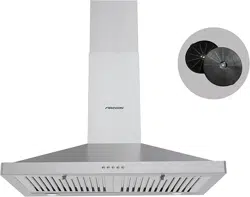
FGS-USD25Z275AC
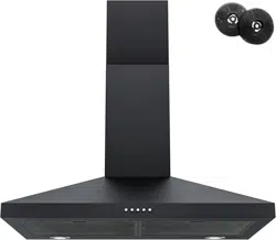
FGS-UBD15D675CC
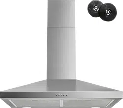
FGS-USD12D675CC
FGS-USD28D775CC
................................................ ........
2
...................................
2
...........
...................................................
...........................................................
...........................................................
6
.
.
.
.
.
.
.
.
.
.
.
.
.
.
.
.
.
.
.
.
.
.
.
.
.
.
.
.
.
.
.
.
.
.
.
.
.
.
.
.
.
.
.
.
.
.
.
.
.
.
.
.
.
.
.
.
.
.
7-8
...........................................................
...........................................................
Filter Installation
Installation
...........
.
.
.
.
.
.
.
.
.
.
.
.
.
.
.
.
.
..............
10-11
...........................................................
Operation
....................................................
Introduction
Safety Precaution
Air Outlet Installation Method
................
9
5-6
Installation Instructions
....
CONTENT
....................................................................
3-4
.
.
.
.
.
.
.
.
.
.
.
.
.
.
.
.
.
.
.
.
.
.
.
.
.
.
.
.
12-13
14
.
.
.
.
.
.
.
.
.
.
.
.
.
.
.
.
.
.
.
.
.
.
.
.
.
.
.
.
.
.
.
.
.
.
.
.
.
.
.
.
.
.
.
.
.
.
.
.
.
.
.
.
.
.
.
.
.
.
.
.
.
.
.
.
.
.
.
.
.
.
.
.
.
.
.
.
.
.
.
.
.
.
.
.
.
.
.
.
.
.
.
.
.
.
.
.
.
.
.
.
.
.
.
.
.
.
.
.
.
.
.
.
.
.
.
.
.
.
Maintenance
Trouble-Shooting
..............
14
...........................................................
Environmental Protection
...........
............
...................
...........
......................
.................................................
..........................................
.................................
.................
Parts Diagram
........................................
21
Introduction
Thank you for choosing this cooker hood.
This instruction manual is designed to provide you with all required
instructions related to the installation, use and maintenance of the
appliance.
In order to operate the unit correctly and safely, please read this
instruction manual carefully before installation and usage.
Accessible parts may become hot when used with cooking appliance.
CAUTION:
Never let the children operate the machine.
Clean the cooker hood according to the instruction manual and keep the
unit from danger of burning. There is a fire risk if cleaning is not carried
out in accordance with the instructions.
Please keep the kitchen room a good convection before connecting this
appliance; Please check that the power supply cord is undamaged. A
damaged supply cord must be replaced by qualified service personnel only.
Regulations concerning the discharge of air have to be fulfilled.
This appliance can be used by children aged from 8 years and above
also the persons with reduced physical, sensory or mental capabilities
or lack of experience and knowledge if they have been given supervision
or instruction concerning use of the appliance in a safe way and
understand the hazards involved. Children shall not play with the
appliance. Cleaning and user maintenance shall not be made by
children without supervision.
The cooker hood is for home use only, not suitable for barbecue,
roast shop and other commercial purpose.
If the supply cord is damaged, it must be replaced by the manufacturer,
its service agent or similarly qualified persons in order to avoid a hazard.
Electrical Shock Hazard
Only plug this unit into a properly earthed outlet.
If you have doubts, seek advice from a suitably qualified engineer.
Safety Precaution
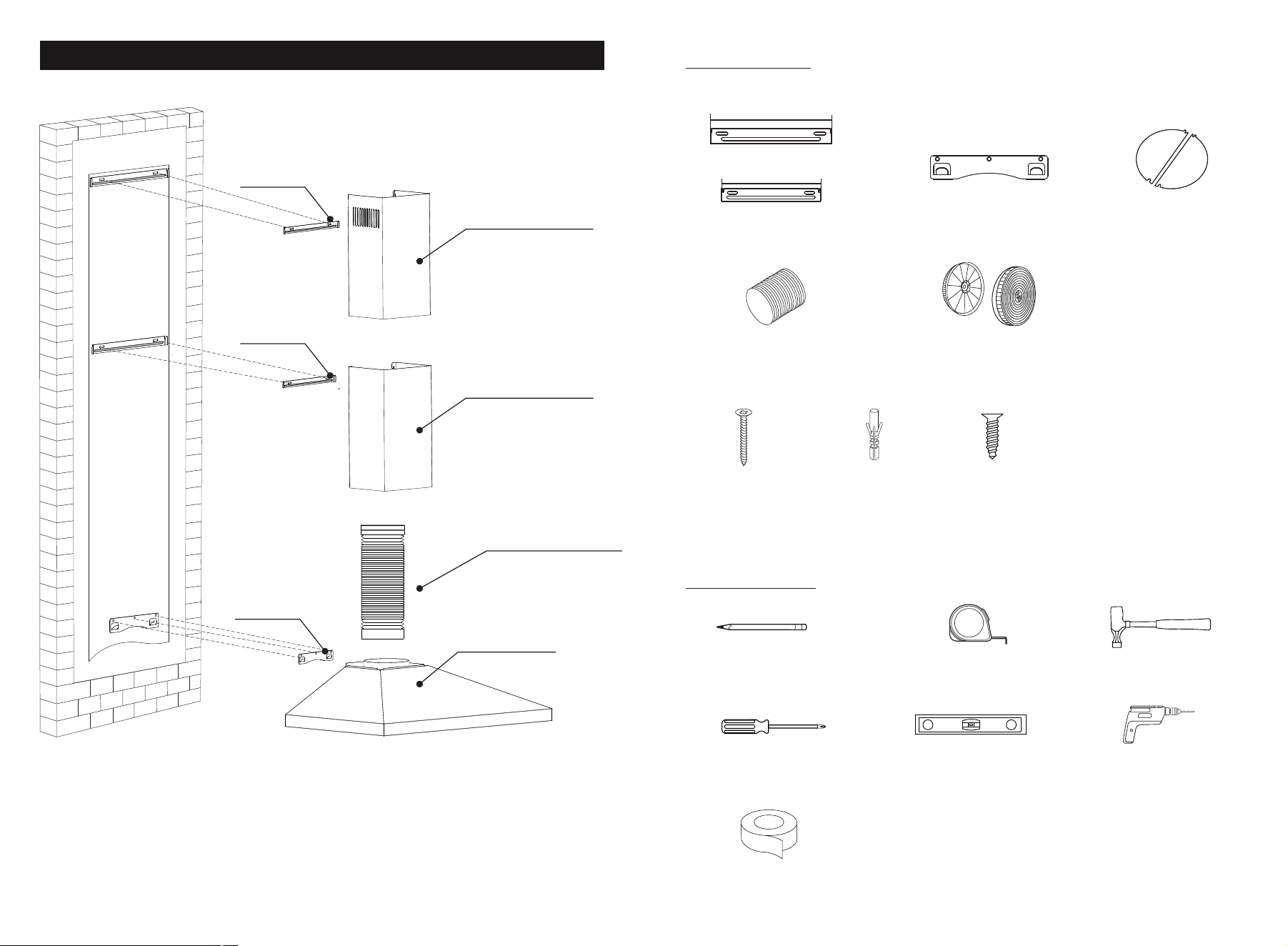
St3×10
×4
St4×30
×11
φ5×φ8
×11
Measuring tape
Screwdriver
Pencil Hammer
Electric drill Level
43
Range Hood Hook
Dampers
Flexible Pipe
Parts Diagram
1.Top Chimney
(Inner Chimney)
2.Bottom Chimney
(Outer Chimney)
3.Exhaust Pipe
4. Core Unit
Charcoal Filters
Upper Chimney Bracket
Lower Chimney Bracket
Parts Supplied
Duct Tape
(2 screws extra)
Hook
Upper Bracket
Lower Bracket
8"
7.6"
ToolsRequired
Mou
nt
i
ng p
aper
(Please refer to the model list on the last page)
Prepare for installation:
b.Before installation, turn the
unit off and unplug it from the
outlet.
c. The cooker hood should be
placed at a distance of 25.6"~30"
above the cooktop for the best
effect.
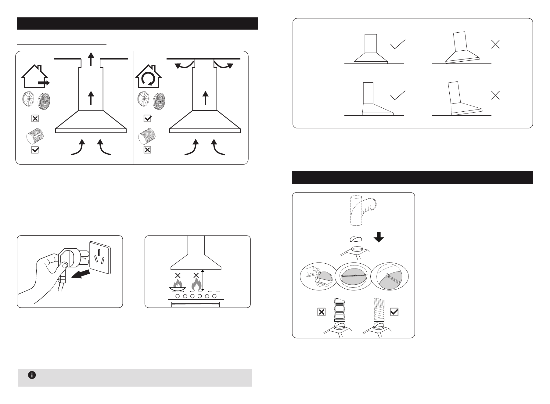
DUCTED OPTION RECIRCULATION OPTION
25.6"~30"
a. If you have an outlet to the outside, your cooker hood can be connected
as above picture by means of a pipe (with an interior diameter of 150mm).
If you don’t have an outlet to the outside, you can go with recirculation
mode by using charcoal filters.
Installation Instructions
65
After hanging the unit on the wall, ensure the range hood is straight and
horizontal.
φ150
Installation method for 150mm
diameter pipe: insert the one-way
-value as the pic and fix the duct.
Attention: The bump of the one-
way-value must be upward.
The pipe near the air outlet need
to be fully extended.
Air Outlet Installation Method
CORRECT WRONG
CORRECT WRONG
Level
Upright
Note
No open flames directly approach to the range hood.
Note: The power cord is 36 (in) L . It is not recommended that user
replace the power cord or cut the power cord.
87
Installation
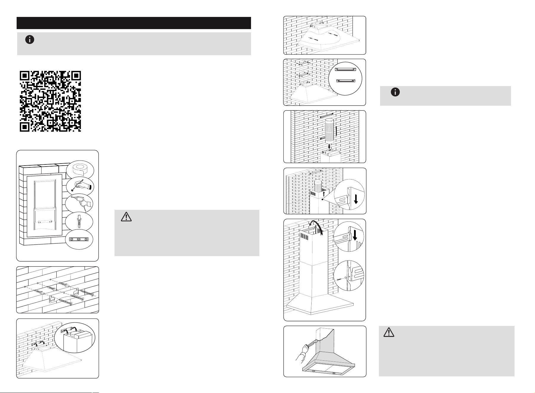
1. After drilling the 2 holes and fixing the
bracket, hang the chimney cover by matching
the both side lock.(Pic1)
There are 2 methods for installing the
chimney cover. Please check the below
pic for reference.
Put the upper chimney into lower chimney .
Then pulling out the upper chimney upwards.
Adjust to reach the height required.
Lift the cooker hood and hang onto
the wall hook.
Drill 3 x 8mm holes to accommodate the
bracket. Screw and tighten the hook
onto the wall with the screws & plastic
wall anchors provided.
Need to drill 2x8mm extra holes & fixing
screws & plastic wall anchors before
installation.
Fix the one-way-value to the air outlet
of the cooker hood, and then attached
the pipe onto the air outlet as picture.
Prepare pencil, electric drill, plastic wall
anchors and level before installation.
Recommended installation height:27.6"
Required minimum installation height: 25.6"
Mark the position and drill 2 holes for
each chimney bracket and tighten the
bracket with screws.
The longer bracket is upper
chimney bracket
Note
Outer Chimney
Inner Chimney
2. After drilling the 2 holes and fixing the
bracket, install the chimney cover by locking
with 2 screws in both side holes.(Pic2)
φ8mm
1.Stick the installation template on the wall.
2.Drill the holes which showing on the template.
Peel off the paper after drilling the holes.
The chimney covers height can be adjusted
from 500mm to 750mm.
CAUTION:
(pic2)
(3*10mm screw)
(pic1)
Please remove the white/blue protective
film on the rangehood,chimney covers
and baffle filters.
BEFORE USE
CAUTION:
Note
Please connect the power supply to test and confirm that the
power is on before installing this wall mount range hood.
(1) Watch the installation video:
(2) Refer to the installation instructions:
In order to know how to install this wall mount
range hood more intuitively, please scan the
QR code to watch the installation video.
109
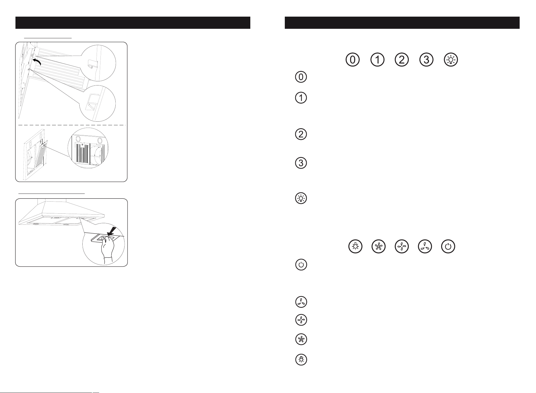
Filter Installation
1.Line up filter hooks to holes in unit.
2. Lift filter for hoohs to go into holes.
3. Lock Filter into place.
Baffle Filter:
Aluminium Filter:
Press button in and down
1.
3.
2.
Push Button
OFF Button
Turn off the fan.
Low Speed Button
Starts the fan at low speed .
It is suitable for simmering and cooking
which does not make much steam.
Medium Speed Button
Starts the fan at medium speed.
This is ideal for ventilation during standard cooking operation.
High Speed Button
Starts the fan at high speed.
This is ideal for when a high density of smoke or steam has
been produced.
Light Button
Used for turning on/off the light.
Operation
Electronic Button
OFF Button
Press to turn unit Off.When motor is running,
press once to delay shut-off for 1 minute,
or press twice to shut off immediately.
Lowest Fan Setting
Medium Fan Setting
Highest Fan Setting
Light. Press to turn light on / off.
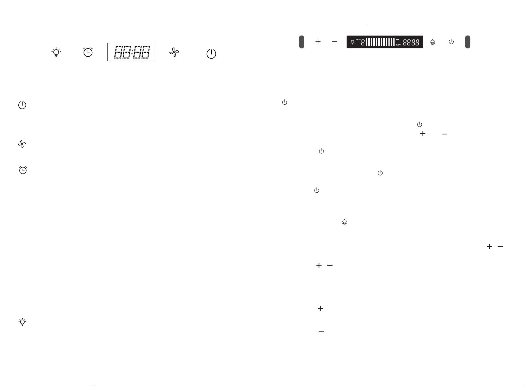
Touch control
During activated mode, press speed button to operate the machine
from 1st speed - 2nd speed - 3rd speed - Stop.
a,Delay function: When machine is running, press timer button to
access into delay function.Choose the time and without any operation
for 10s, the machine will start the count down and will be off after
count down is finishing.
Delay timer setting: Default time is 3 mins.When the delay button is
flashing, press this button to increase minutes.(Delay timer can be
set from 1-60mins)
Count down mode:The timer button illuminates in blue and the
machine will create “Bi”sound at the last 3 sec to finish the count
down.If you want to stop the count down, press this button again to
exit this mode.
During standby mode, press the ON/OFF button for 0.5 sec to
access activated mode.In activated mode, this button is illuminated
and speed button can be operated. Press ON/OFF button again can
access into standby mode.
1211
Connect to the power, it access into standby mode with “Bi”sound.
LED screen shows time in blue color and only light button can be
operated . In activated mode, all icons are not illuminated.
b, Timer setting function: During standby or activated mode, press
this button for 1s to access into timer setting function with the LED
screen timer flashing. Press timer button to increase hour and press
light button to increase min. After setting, press this button again or
wait for 10 sec without any operation to settle down the timer.
Press light button to control light ON or OFF.
Electrify function
After connect to the power, the indicator will be power-on and off
after 1 second. Display show up white color and 12:00 then enter
to the shutdown mode.
Switch function
Press this button to access into standby or shutdown mode.
Time delay function
①Time delay setting: Long press the “ ” button for 3 seconds, the
display shows “5:00” and flash, press “ ” “ ”to adjust the
shutdown time (1-60 minutes), long press can adjust continuously.
Press “ ” or 10 seconds without operation, timer will be saved
and return to shutdown mode.
②Delay shutdown: Press “ ” to enter time delay mode, the indicator
lights on and start the countdown (5 minutes by default);
press“ ” again, can off the machine and return to shutdown mode.
Long press switch for 3 second, can exit time delay function.
Lighting function:
① Press this “ ” button to control light ON/OFF.
②Clock setting: Long press the lighting button for 3 seconds, all the
indicators light on and flash, the display will flash, press “ ”
to adjust hour. Press lighting button to access into minutes setting,
press “ ”adjust minutes. Press light button again or no
operation for 10 sec to confirm clock setting.
Motor function: (9 speed)
Increase:
Press “ ”to set speeds from 1 - 9 speeds.
Decrease:
Press “ ”button to decrease the speeds.
Before cleaning switch the unit off and pull out the plug.
I. Regular Cleaning
Use a soft cloth moistened with hand-warm mildly soapy water
or household cleaning detergent. Never use metal pads, chemical,
abrasive material or stiff brush to clean the unit.
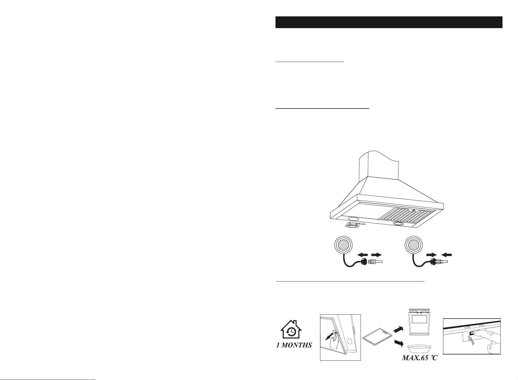
II. LED Light Replacement
Switch the unit off and unplug the appliance.
III. Filter and charcoal filters replacement
In order to install the carbon filter, the grease filter should
be detached first. Press the lock and pull it downward.
CAUTION: LAMP UNIT MAY BE HOT!
WAIT UNTIL THE UNIT IS COOL. BEFORE attempting to replace
the LED lamps make sure the unit is powered off and UNPLUGGED.
Maintenance
1413
Somatosensory
a. In the off mode, move your hand from left to right can control
the motor change from 1 to 9 speed in circle.
b. During power on or motor is running, move your hand from
right to left distance to access into 3 mins count down.
Move your hand from right to left again can off the machine.
Remark: Wave sensor distance from switch is around 11cm to 15cm.
1615
Filters: To avoid fires, clean thoroughly once a month
or wheneverthe display pilot lights up (if fitted). To do so,remove
the filters and soak inhot water and detergent for an hour.If using
a dishwasher,position the filters vertically to improve the cleaning
process.
Important Notice:
1.Make sure the filter is securely locked. Otherwise, it would loosen
and cause abnormal noise and danger.
2.Using charcoal filter would reduce the air flow of the range hood.
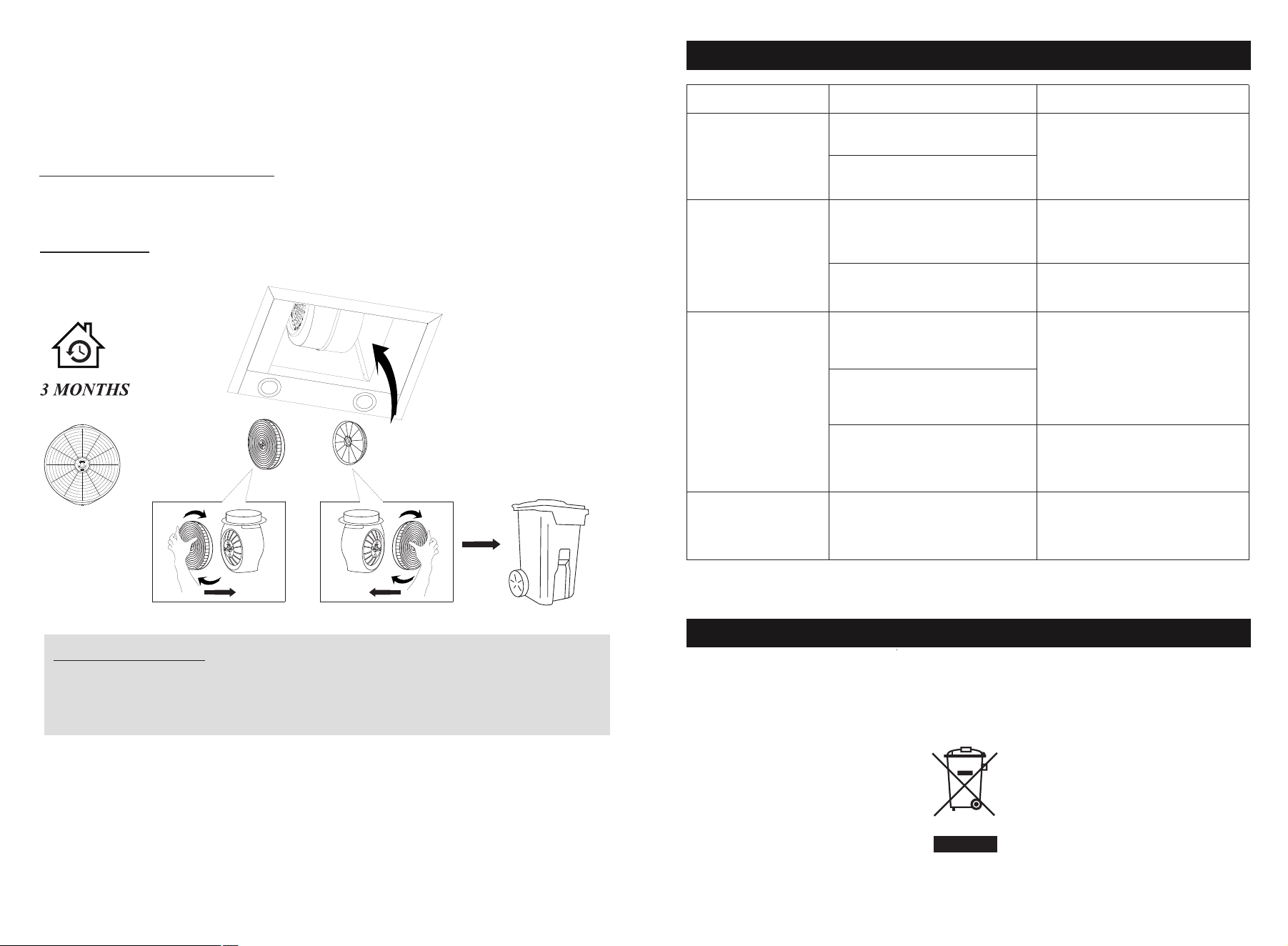
VI.Charcoal filter life time: Suggest changing to new one every 3
months (According to different kitchen condition, the life time of
charcoal filter might be longer or shorter than 3 months).
Installation: Fix carbon filter into the unit and turn it in as below
picture shows. Repeat the same on the other side.
Fault Cause Solution
Waste electrical products should not be disposed of with household waste.
Please recycle where facilities exist.
Check with your Local Authority or retailer for recycling advice.
The fan blade is jammed.
The motor is damaged.
Light is burnt out.
Power cord is loose.
Light on,but fan
does not work
Both light and fan
do not work
Serious Vibration
of the unit
Suction
performance not
good
Too far distance
between the unit
and the cooktop.
The unit is not hung
properly on the bracket.
The fan motor is not
fixed tightly.
The fan blade is
damaged.
Switch off the unit and
repair by qualified
service personnel only.
Replace the LED light
with correct rating.
Plug into the power
supply again.
Switch off the unit and
repair by qualified
service personnel only.
Take down the unit and
check whether the bracket
is in proper location.
Readjust the distance
between 25.6"-30"
Environmental Protection
Trouble-Shooting
Model List
Range Hood Model No.
FGS-USD24Y75AC
FGS-UBD24Y75AC
FGS-USD24Y75CC
FGS-USD25Y75AC
FGS-USD25Y75CC
Charcoal Filter Model No.:
CC110
CC170
FGS-UBD15D675CC
FGS-UBD12D675CC
FGS-USD28D775CC
FGS-USD25Z275AC CC130