重要提示:
本設備使用 R32 輕度易燃製冷劑。
在安裝或操作新空調機組之前,請仔細閱讀本手
冊。請妥善保管本手冊以備將來參考。
適用的型號、技術資料見機身銘牌。
窗式空調器
用戶手冊與安裝手冊
RAC-07G3CVRGR-HK
RAC-09G3CVRGR-HK
RAC-12G3CVRGR-HK
RAC-18G3CVRGR-HK
RAC-07G3CVRG-HK RAC-07G3CVG-HK
RAC-09G3CVG-HK
RAC-12G3CVG-HK
RAC-18G3CVG-HK

Precautions
安全須知
警告
操作和安裝前請閱讀安全須知
由於忽視說明而導致錯誤安裝可能會產生嚴重的損壞或傷害。
1. 安裝
- 製冷劑管道應符合國家氣體法規。
- 機械連接應便於維護。
- 在需要機械通風的情況下,通風口應保持暢通無阻。
- 處理使用過的產品時,應根據國家規定妥善處理。
2. 維修
- 任何操作或拆解製冷劑回路的人員都必須持有行業認可的評估機構頒發的有效證書,該證書授
權其根據行業認可的評估規範安全處理製冷劑。
3. 維護和修理需要其他技術人員的協助,應在有能力使用易燃製冷劑的人員監督下進行。
4. 除廠家推薦的方法外,請勿使用任何其他方法加速除霜過程或進行清潔。
5. 電器應存放在沒有持續工作的點火源的房間內(例如:明火、工作的燃氣器具或電加熱器)。
6. 請勿讓異物(油、水等)進入配管。此外,在保管配管時,請通過夾緊、膠帶等將開口密封好。
7. 請勿刺穿或燃燒。
8. 請注意,製冷劑可能沒有氣味。
9. 所有影響安全措施的工作程式只能由合格人員進行。
10. 電器應存放在通風良好的區域,房間大小應與具體操作面積相符。
11. 存放電器時應防止發生機械損壞。
12. 電器使用輕度易燃製冷劑R32,並經測試符合IEC 60335-2-40。有關型號並沒有最小房間面積
要求。
13. 安裝高度不得低於0.75米。
- 安裝必須由授權經銷商或受過專業訓練的人員進行。
小心
小心
小心
警告
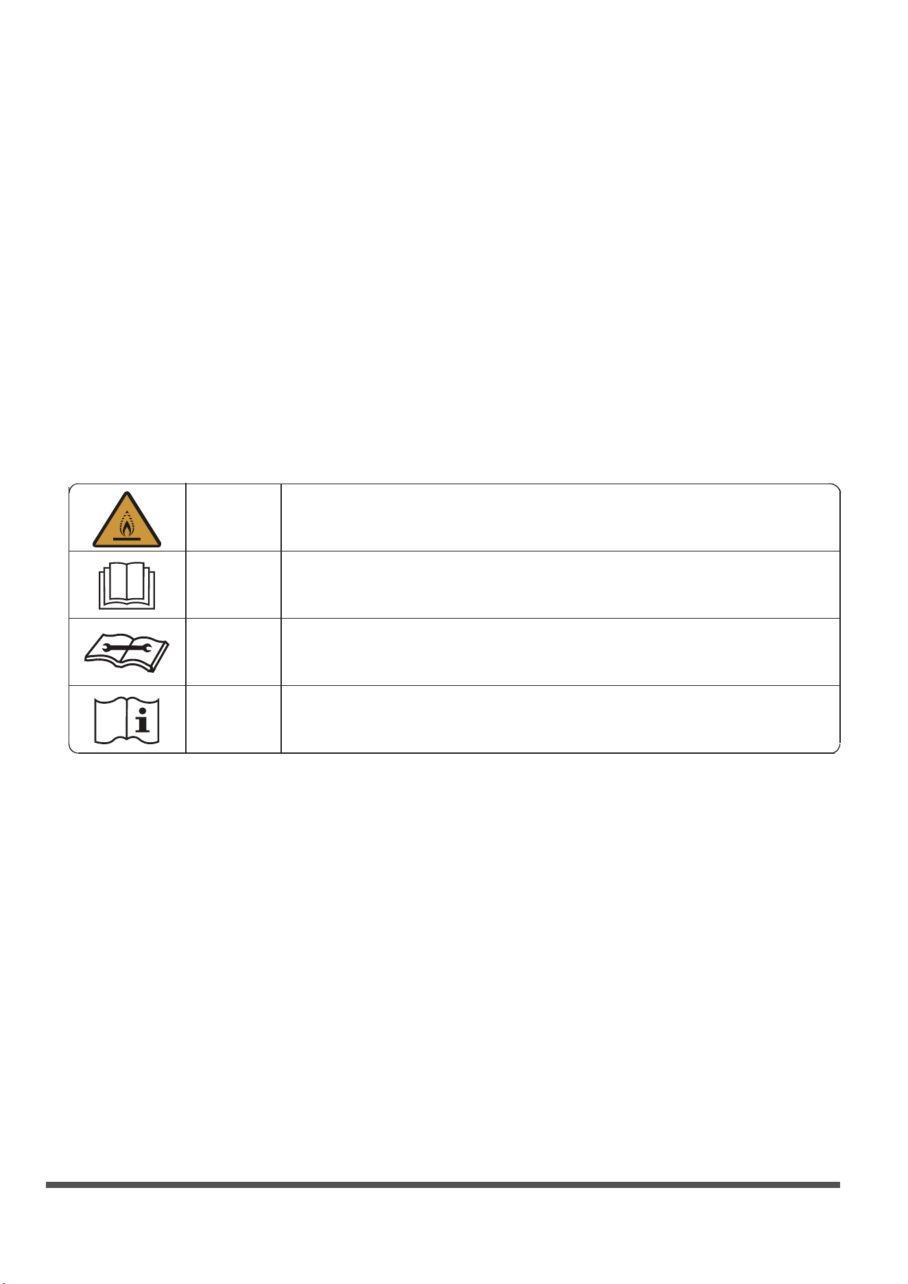
本機顯示符號的說明
裝置運輸、標記和儲存
1. 含有易燃製冷劑的設備的運輸
遵守運輸法規
2. 使用標誌標記設備
遵守當地法規
3. 使用易燃製冷劑的設備的處置
遵守國家法規
4. 設備/電器的存放
設備的儲存應按照製造商的說明進行。
5. 已包裝(未售出)設備的存放
儲存包裝保護裝置的結構應確保包裝內的設備發生機械損壞時不會導致製冷劑洩漏。
允許存放在一起的最大設備件數根據當地法規確定。
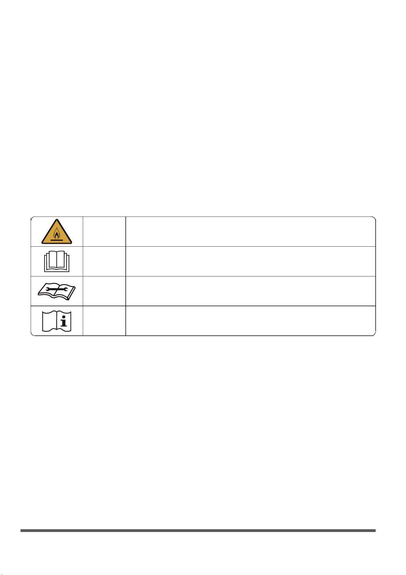
此符號表示本電器使用輕度易燃製冷劑。如果製冷劑洩漏並暴露於外部
火源,則有著火的風險。
此符號表示應仔細閱讀操作手冊。
此符號表示維修人員應參考安裝手冊處理此設備。
此符號表示操作手冊或安裝手冊提供相關資訊。
目錄
歐洲處置指南
特別提示
警告 ......................................................................................................03
裝置部件識別 ........................................................................................09
操作說明 ...............................................................................................10
保養和維護 ............................................................................................11
排水 ......................................................................................................12
安裝說明 ...............................................................................................13
故障排除 ...............................................................................................15
規格 ......................................................................................................16
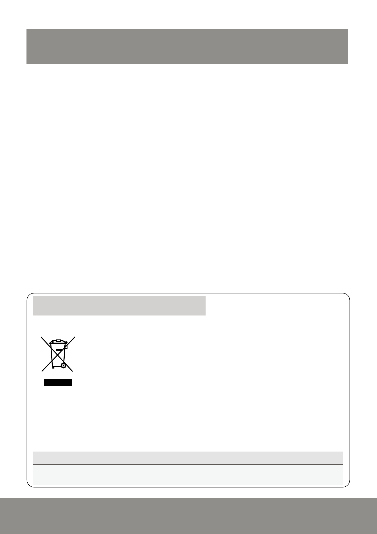
產品或其資料上顯示的此標記表示不得將廢棄電氣和電子設備與一般生活垃圾混合。
正確處置本產品(廢棄的電氣和電子設備)
本電器包含製冷劑和其他潛在危險材料。處理此電器時,法律要求進行特殊收集和處理。請勿將本產品作為
家庭垃圾或未分類的市政垃圾處理。
處置本電器時,您有以下選擇:
• 在指定的市政電子垃圾收集設施處處理設備。
• 購買新電器時,零售商將免費收回舊電器。
• 製造商將免費收回舊電器。
• 將電器出售給經過認證的廢金屬經銷商。
在森林或其他自然環境中處置本電器會危及您的健康並對環境有害。有害物質可能會洩漏到地下水中並進入
食物鏈。
3
請在操作和安裝前閱讀
警告
產品使用警告
警告
清潔和維護警告
小心
警告
此符號表示可能造成人員受傷或死亡。
小心
由於忽視說明而導致錯誤安裝可能會產生嚴重的損壞或傷害。潛在損壞或傷害的嚴重性分
為警告或小心。
此符號表示可能造成財產損失或嚴重後果。
本電器可供身體、感官或精神能力有缺陷或缺乏經驗和知識的人員(包括兒童)使用,前提是有負責人員提供有
關電器使用的監督或指導。應監督兒童以避免其玩耍本電器。
• 如果出現異常情況(如燒焦味),請立即關閉電器並斷開電源。請致電您的經銷商獲取有關避免觸電、火災或
人身傷害的指導。
• 請勿將手指、杆或其他物體插入進風口或出風口,否則可能會導致人身傷害,因為風扇可能在高速旋轉。
• 請勿在本機附近使用髮膠、油漆或塗料等易燃噴霧劑,否則可能會導致火災或燃燒。
• 請勿在可燃氣體附近或周圍運行空調。散發的氣體可能會聚集在設備周圍並導致爆炸。
• 請勿在浴室或洗衣房等潮濕的房間內使用空調。過多接觸水會導致電氣元件短路。
• 請勿將身體長時間直接暴露在冷空氣中。
• 請勿讓兒童玩耍空調。兒童在設備周圍時必須始終受到監督。
• 如果空調與燃燒器或其他加熱設備一起使用,請徹底通風,以免缺氧。
• 在某些功能環境中,如廚房、伺服器機房等,強烈建議使用專門設計的空調機組。
• 如果發出奇怪的聲音、氣味或煙霧,請拔下設備插頭或斷開電源。
• 為進一步優化設備性能,請在操作期間保持門窗關閉。
• 開箱安裝時要注意,鋒利的邊緣可能會造成傷害。
• 清潔前關閉設備並斷開電源,否則可能會導致觸電。
• 請勿使用過多的水清潔空調。
• 請勿使用可燃清潔劑清潔空調,否則可能會引起火災或變形。
• 如果長時間不使用,請關閉空調並斷開電源。
• 在暴風雨期間關閉並拔掉設備插頭。
• 確保冷凝水可以從設備中暢通無阻地排出。
• 請勿用濕手操作空調,否則可能會導致觸電。
• 請勿將設備用於預期用途以外的任何其他目的。
• 請勿攀爬或在室外機頂部放置物體。
• 請勿讓空調長時間在門窗打開或者在濕度非常高的情況下運行。
• 本設備使用 R32 輕度易燃製冷劑。

4
電氣警告
產品安裝警告
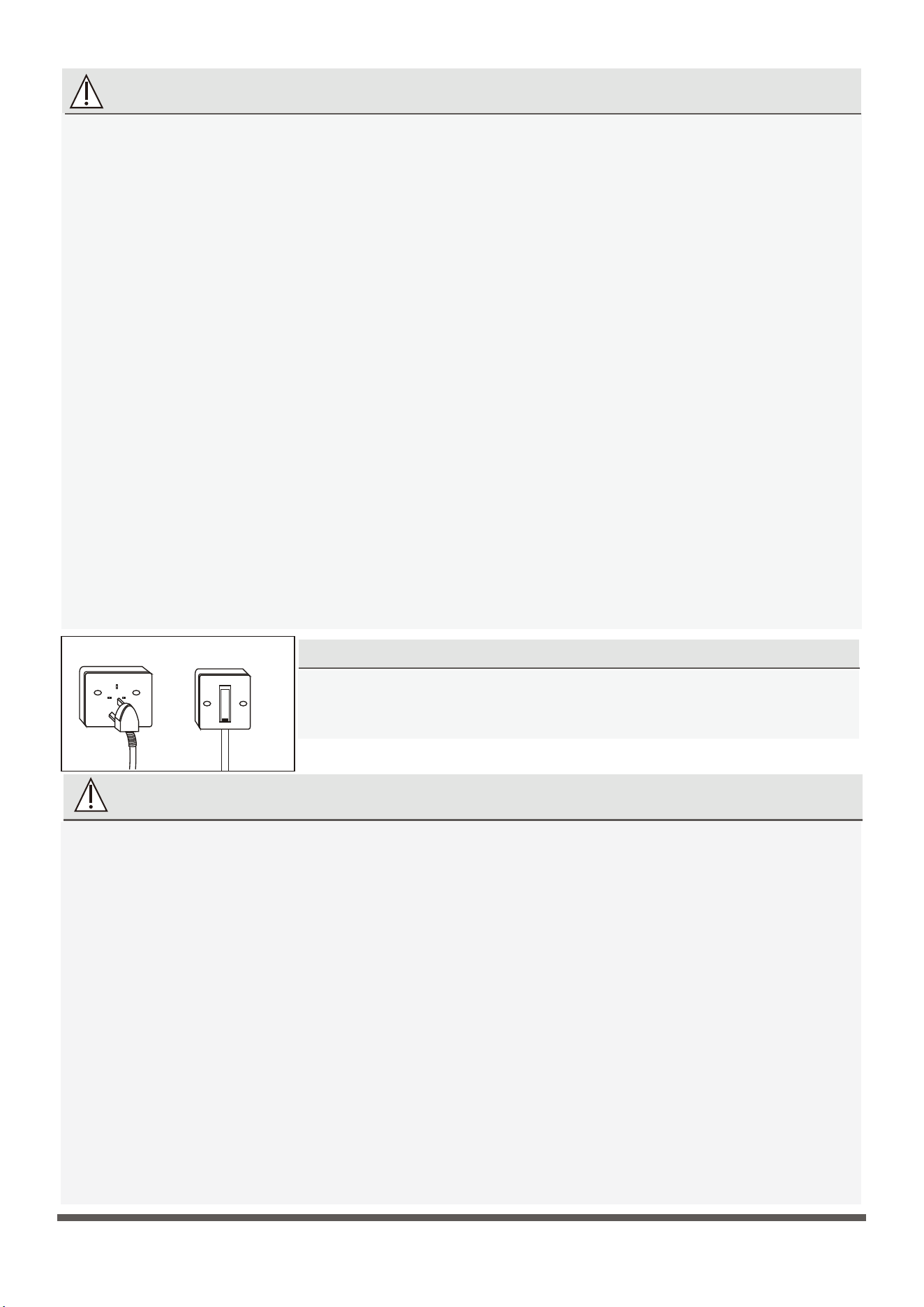
注意保險絲規格
壁式插座
空氣斷路開關
• 僅使用指定的電源線。如果電源線損壞,必須由製造商、其服務代理商或類似的合格人員更換,以避免發生危
險。
• 保持電源插頭清潔。清除積聚在插頭上或插頭周圍的任何灰塵或污垢。髒插頭會導致火災或觸電。
• 請勿拉扯電源線以拔下設備插頭。請握住插頭並將其從插座中拔出。直接拉扯會損壞電源線,從而導致火災或
觸電。
• 請勿修改電源線的長度或使用延長線為設備供電。
• 請勿與其他電器共用電源插座。電源供應不當或不足會導致火災或觸電。始終安裝斷路器和專用電源電路。
• 如果插座鬆動或損壞,請勿使用。
• 請勿在電源線上放置重物,並確保電源線沒有被壓扁,否則有火災或觸電的危險。
• 如果水進入設備,請在電源插座處關閉設備並關閉斷路器。拔下電源插頭或斷開設備電源,並聯繫合格的維修
技術人員。
• 產品安裝時必須正確接地,否則可能會發生觸電。
• 對於所有電氣工作,請遵循所有當地和國家接線標準、法規以及設備頂部面板上的電氣連接圖。
• 如果將電源連接到固定接線,應使用所有極間至少有3毫米間隙且漏電流可能超過10mA的全極斷開裝置,剩餘
電流裝置(RCD)的額定剩餘工作電流不超過30mA,並且必須按照接線規則將斷開裝置包含在固定接線中。
• 本機通過電源線接地,確保裝置正確接地。壁式插座(空氣開關)應有可靠的地線。
• 設備應配備獨立電路,斷路器/保險絲額定值應與電源線和壁式插座的額定值相同。電源線導體根據顏色區分,
如機器頂部的接線圖所示。
1. 安裝必須由授權經銷商或受過專業訓練的專業人員進行。有缺陷的安裝會導致漏水、觸電或火災。
2. 安裝必須按照安裝說明進行。安裝不當會導致漏水、觸電或火災。(在北美,只能由授權人員按照NEC和CEC
的要求進行安裝。)
3. 聯繫授權服務技術人員修理或維護本設備。本電器應按照國家接線規定進行安裝。
4. 只能使用附帶的附件、零件和指定的零件進行安裝。使用非標準部件會導致漏水、觸電、火災,並可能導致設
備故障。
5. 將設備安裝在能夠支撐設備重量的穩固位置。如果選擇的位置不能支撐設備重量,或者安裝不當,設備可能會
掉落並導致嚴重的人身傷害和損壞。
6. 按照本手冊中的說明安裝排水管道。排水不當可能會對您的房屋和財產造成損壞。
7. 對於帶有輔助電加熱器的裝置,請勿將裝置安裝在距離任何可燃材料1米(3英尺)的範圍內。
8. 請勿將設備安裝在可能暴露於可燃氣體洩漏的位置。如果可燃氣體積聚在本機周圍,可能會引起火災。
9. 在所有工作完成之前請勿打開電源。
10. 移動或重新安置空調時,請諮詢有經驗的維修技術人員進行裝置的斷開和重新安裝。
11. 關於如何將電器安裝到支架上,請閱讀“安裝說明”部分的詳細資訊。
空調的電路板(PCB)設計有保險絲以提供過流保護。電路板上印有保險
絲的規格,如220V。
5
使用R32製冷劑的警告
- 除廠家推薦的方法外,請勿使用任何其他方法加速除霜過程或進行清潔。
- 電器應存放在沒有持續工作的點火源(例如:明火、工作的燃氣器具)的房間內,並且電器附近不得有火源
(例如:工作的電加熱器)。
- 請勿刺穿或燃燒。
- 請注意,製冷劑可能沒有氣味。
- 應遵守國家氣體法規。
- 保持通風口暢通無阻。
- 妥善存放電器以防止發生機械損壞。
- 電器應存放在通風良好的區域,房間大小應與具體操作面積相符。
- 任何操作或拆解製冷劑回路的人員都必須持有行業認可的評估機構頒發的有效證書,該證書授權其根據行業認
可的評估規範安全處理製冷劑。
- 維護和修理需要其他技術人員的協助,應在有能力使用易燃製冷劑的人員監督下進行。
- 請仔細按照說明操作、安裝、清理、維修空調,以免造成任何損壞或危險。空調使用輕度易燃製冷劑R32。維
修或處置空調時,應妥善回收製冷劑(R32),不得直接排放到空氣中。
- 空調周圍不得有任何明火或開關等可能產生火花/電弧的裝置,以免引起易燃製冷劑著火。請仔細按照說明存放
或維護空調,以免發生機械損壞。
- 空調使用易燃製冷劑。請仔細按照說明進行操作,以免發生任何危險。
重要說明:安裝或操
作新空調機組之前請
仔細閱讀本手冊。
警告:低燃速材料
(IEC 60335-2-40:2018適用於
R32型號)
6
警告
小心
小心
小心
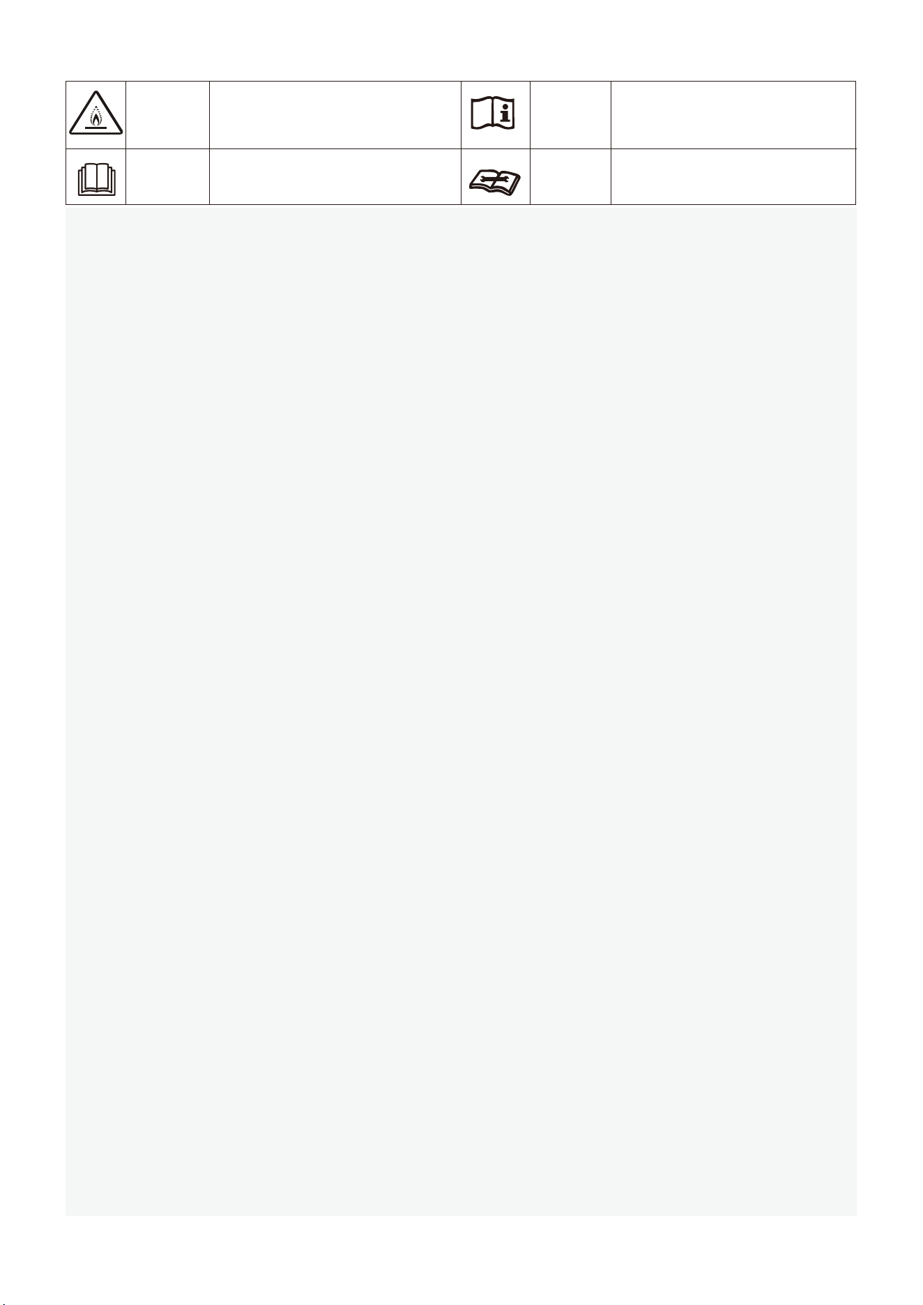
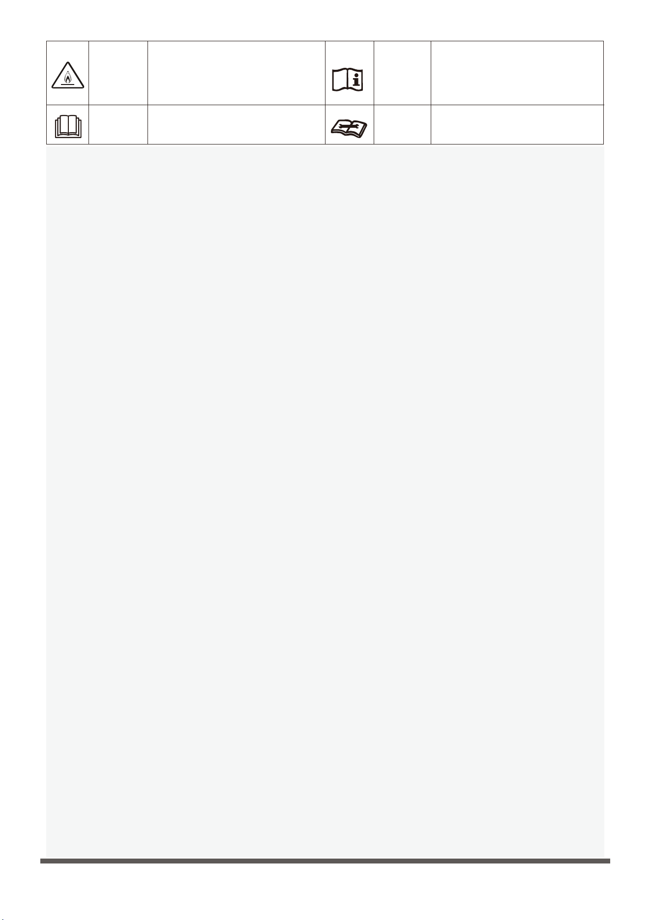
此符號表示本電器使用輕度易燃製
冷劑。如果製冷劑洩漏並暴露於外
部火源,則有著火的風險。
此符號表示應仔細閱讀操作手冊。
此符號表示維修人員應參考安
裝手冊處理此設備。
此符號表示操作手冊或安裝手
冊提供相關資訊。
1. 含有易燃製冷劑的設備的運輸
遵守運輸法規
2. 使用標誌標記設備
遵守當地法規
3. 使用易燃製冷劑的設備的處置
遵守國家法規
4. 設備/電器的存放
設備的儲存應按照製造商的說明進行。
5. 已包裝(未售出)設備的存放
儲存包裝保護裝置的結構應確保包裝內的設備發生機械損壞時不會導致製冷劑洩漏。允許存放在一起的最大
設備件數根據當地法規確定。
6. 維修資訊
1) 現場檢查
在開始對含有易燃製冷劑的系統進行操作之前,必須進行安全檢查以確保將著火風險降至最低。對於製冷系
統的維修,在對系統進行操作之前應遵守以下預防措施。
2) 工作程式
工作應在受控程式下進行,以最大程度地減少工作期間出現易燃氣體或蒸汽的風險。
3) 一般工作區
所有維修人員和在當地工作的其他人員都應瞭解所進行工作的性質。應避免在密閉空間內工作。工作區周圍
的區域應分隔開。通過控制易燃材料,確保該區域內的狀況安全。
4) 檢查是否有製冷劑
在工作之前和工作期間,應使用適當的製冷劑檢測器檢查該區域,以確保技術人員瞭解潛在的易燃環境。確
保所使用的洩漏檢測設備適用于易燃製冷劑,即無火花、充分密封或本質安全。
5) 配備滅火器
如果對製冷設備或任何相關部件進行任何熱加工,應準備好合適的滅火設備。在充注區附近放置一個乾粉或
二氧化碳滅火器。
6) 無火源
任何人在可能暴露於含有或曾經含有易燃製冷劑的任何管道工程的製冷系統上執行操作時,不得以可能導致
火災或爆炸風險的方式使用任何點火源。所有可能的火源,包括吸煙,都應遠離安裝、維修、拆卸和處置場
所,在此期間,易燃製冷劑可能會釋放到周圍空間。在開始工作之前,應檢查設備周圍的區域,以確保沒有
易燃危險或著火風險。應張貼禁止吸煙標誌。
7) 通風區域
在進入系統或進行任何高溫作業之前,確保該區域處於開放狀態或充分通風。在工作過程中應保持一定程度
的通風。通風應安全地分散釋放的製冷劑,最好將其從外部排放到大氣中。
8) 製冷設備檢查
更換的電氣元件應適合用途並符合正確的規格。應始終遵守製造商的維護和服務指南。如有疑問,請諮詢製
造商的技術部門尋求幫助。對使用可燃製冷劑的裝置應進行以下檢查:充注量與含製冷劑部件安裝房間的大
小一致;
通風設備和出風口運行正常,沒有堵塞;
如果使用間接製冷回路,應檢查二次回路是否存在製冷劑;設備上的標記仍然清晰可見。難以辨認的標記和
標誌應予以糾正;製冷管道或部件的安裝位置應避免暴露於任何可能腐蝕含製冷劑部件的物質,除非這些部
件由具有固有抗腐蝕能力的材料製成,或者有適當的保護以防止腐蝕。
9) 檢查電氣設備
電氣元件的維修和維護應包括初始安全檢查和元件檢查程式。如果存在可能危及安全的故障,則在妥善處理
之前,不得將電源連接到電路。如果故障不能立即糾正,但需要繼續運行,則應採用適當的臨時解決方案。
應將情況報告給設備所有者,以便通知所有各方。初始安全檢查應包括:
本機顯示符號說明(僅適用於採用R32製冷劑的機組):

7
電容器放電:應以安全的方式進行,以避免產生火花的可能性;
充注、回收或清洗系統時,沒有帶電的電氣元件和線路暴露在外;
接地連接具有連續性。
7. 密封元件的修理
1) 在修理密封元件過程中,在拆除密封蓋等之前,應將所有電源與正在工作的設備斷開。如果在維修過程中必須
為設備供電,則最關鍵的點應有永久運行的洩漏檢測形式,以警告潛在的危險情況。
2) 應特別注意以下事項,以確保在對電氣元件進行操作時,不會改變外殼從而影響防護等級,包括電纜損壞、連
接數量過多、端子不符合原始規格、密封件損壞、壓蓋安裝不正確等。
確保設備安裝牢固。
確保密封件或密封材料沒有退化,以確保其能夠起到防止可燃氣體進入的作用。更換零件應符合製造商的規格。
注意:使用矽密封膠可能會抑制某些類型的洩漏檢測設備的有效性。本安組件在處理之前不必隔離。
8. 本安組件維修
請勿在電路上施加任何永久性電感或電容負載,除非確保不會超過所用設備的允許電壓和電流。本安元件是唯
一可以在有易燃氣體的情況下工作的類型。測試設備應處於正確的額定值。只能使用製造商指定的部件更換元
件。其他部件可能會因洩漏而導致大氣中的製冷劑著火。
9. 佈線
檢查佈線是否會受到磨損、腐蝕、過度壓力、振動、銳邊或任何其他不利環境影響。檢查還應考慮壓縮機或風
扇等造成的老化或持續振動的影響。
10. 可燃製冷劑檢測
在任何情況下都不得使用潛在的點火源尋找或檢測製冷劑洩漏。
不得使用鹵素燈(或任何其他使用明火的探測器)。
11. 洩漏檢測方法
以下洩漏檢測方法適用于含易燃製冷劑的系統。應使用電子檢漏儀檢測易燃製冷劑,但靈敏度可能不夠,或
者可能需要重新校準。(檢測設備應在無製冷劑的區域進行校準。)確保檢測器不是潛在的點火源並且適合
所使用的製冷劑。洩漏檢測設備應設置為製冷劑LFL的百分比,並應根據所使用的製冷劑進行校準,並確認
適當的氣體百分比(最大25%)。檢漏液適用於大多數製冷劑,但應避免使用含氯的清潔劑,因為氯可能與
製冷劑發生反應並腐蝕銅管。如果懷疑有洩漏,應移走/熄滅所有明火。如果發現需要釺焊的製冷劑洩漏,
則應從系統中回收所有製冷劑,或將系統中遠離洩漏的部分隔離(通過截止閥)。然後,在釺焊過程之前和
過程中,應通過系統吹掃無氧氮氣(OFN)。
12. 清除和排空
當進入製冷劑回路進行維修或出於任何其他目的時,應使用常規程式。然而,重要的是遵循最佳做法,因為
需要考慮易燃性。不得通過釺焊打開製冷系統。應遵循以下程式:
清除製冷劑;
用惰性氣體吹掃電路;
排空;
再次用惰性氣體吹掃;
通過切割或釺焊打開電路。
應將充注的製冷劑回收到適當的回收鋼瓶中。系統應使用OFN進行沖洗以確保設備安全。這一過程可能需要
重複幾次。此任務不得使用壓縮空氣或氧氣。
沖洗時用OFN打破系統中的真空並繼續填充直到達到工作壓力,然後排放到大氣中,最後抽真空來實現。應
重複此過程,直到系統內沒有製冷劑為止。
當使用最終OFN充注時,系統應排放至大氣壓力以進行工作。如果要在管道上進行釺焊操作,此操作至關重要。
確保真空泵的出口不靠近任何點火源,並且有通風。
13. 充注程式
除常規充注程式外,還應遵循以下要求。確保在使用充注設備時不會發生不同製冷劑的污染。軟管或管線應
盡可能短,以儘量減少其中的製冷劑含量。
鋼瓶應保持直立。
在向系統充注製冷劑之前,確保製冷系統已接地。
充注完成時給系統貼上標籤(如果還未貼)。
應特別注意不要將製冷系統裝得過滿。
在給系統充注之前,應使用OFN對其進行壓力測試。系統應在充注完成後試運轉之前進行洩漏測試。離開現
場前應進行後續洩漏測試。

8
14. 停止運行
在執行此程式之前,技術人員必須完全熟悉設備及其所有細節。建議的良好做法是安全回收所有製冷劑。
在執行任務之前,應採集油和製冷劑樣本,以防在重新使用回收的製冷劑之前需要進行分析。在任務開始之
前,必須連接電源。
a) 熟悉設備及其操作。
b) 電氣隔離系統。
c) 在嘗試該程式之前,請確保:
必要時可使用機械搬運設備來搬運製冷劑鋼瓶;
所有個人防護設備都可用並正確使用;
回收過程始終由合格人員監督;
回收設備和鋼瓶符合相應的標準。
d) 如果可能,抽空製冷系統。
e) 如果無法實現真空,則製作一個歧管,以便可以從系統的各個部分排出製冷劑。
f) 在回收之前確保鋼瓶位於秤上。
g) 啟動回收機並按照製造商的說明進行操作。
h) 請勿過度充注鋼瓶(液體充注體積不超過80%)。
i) 不得超過鋼瓶的最大工作壓力,即使是暫時的。
j) 當鋼瓶正確加注並完成該過程後,確保立即將鋼瓶和設備移出現場,並關閉設備上的所有隔離閥。
k) 回收的製冷劑除非經過清潔和檢查,否則不得充注到另一個製冷系統中。
15. 標籤
設備應貼上標籤,說明其已停用並排空製冷劑。標籤應注明日期並簽名。確保設備上有標籤,說明設備含有
易燃製冷劑。
16. 回收
從系統中移除製冷劑時,無論是為了維修還是停用,建議的良好做法安全是移除所有製冷劑。將製冷劑轉移
到鋼瓶中時,確保僅使用合適的製冷劑回收鋼瓶。確保可以使用正確數量的鋼瓶來容納系統總充氣量。使用
的所有鋼瓶都指定用於回收的製冷劑並有相應標記(即用於回收製冷劑的特殊鋼瓶)。鋼瓶應配有狀態良好
的壓力釋放閥和相關截止閥。空的回收鋼瓶應排空,如果可能,回收之前應冷卻。回收設備應處於良好的工
作狀態,並附有一套關於適用於可燃製冷劑回收的設備的說明。此外,應備有一套校準過並處於良好工作狀
態的秤。軟管應配備無洩漏斷開接頭且狀況良好。在使用回收機之前,檢查是否處於良好的工作狀態,是否
得到了適當的維護,並且所有相關的電氣元件都已密封,以防止在製冷劑洩漏時著火。如有疑問,請諮詢製
造商。
回收的製冷劑應使用適當的回收鋼瓶退回給製冷劑供應商,並安排相關的廢物轉移單。請勿在回收裝置中混
合製冷劑,尤其是在鋼瓶中。如果要清除壓縮機或壓縮機油,請確保將排空到可接受的水準,以確保潤滑劑
中不會殘留易燃製冷劑。排空過程應在將壓縮機返還給供應商之前進行。只能對壓縮機本體採用電加熱來加
速這一過程。從系統中排油時,應安全進行。
當使用易燃製冷劑時,電器應存放在通風良好的地方。
9
工作溫度
當空調在以下溫度範圍之外使用時,某些安全保護功能可能會啟動並導致設備無法使用。
18°C-43°C (64°F-109°F)
17°C-32°C (62°F-90°F)
-5°C-24°C (23°F-76°F)
0°C-27°C (32°F-80°F)
18°C ~ 52°C(64°F ~ 126°F)(適用於特殊熱帶型號)
製冷運行
加熱運行
室外溫度
室外溫度
室內溫度
室內溫度
要進一步優化設備的性能,請執行以下操作:
裝置部件識別
排水接頭( )
[ ] 型號相關
1個 1個 1個
排水盤( )
或
橡膠塞 螺釘
配件
1個 4個
• 保持門窗關閉。
• 房間空調的容量必須適合房間大小,以便高效地運行。
• 請勿堵塞空氣入口或出口。
• 定期檢查和清潔空氣篩檢程式。
• 如果設備電源不是指定額定值±10%,則設備可能無法運行且保險絲可能熔斷。
• 夜間空調發出的噪音會比白天大。這是因為夜間環境噪音相對較低。如果您覺得噪音太大,請將恒溫器切換到較低的數字。
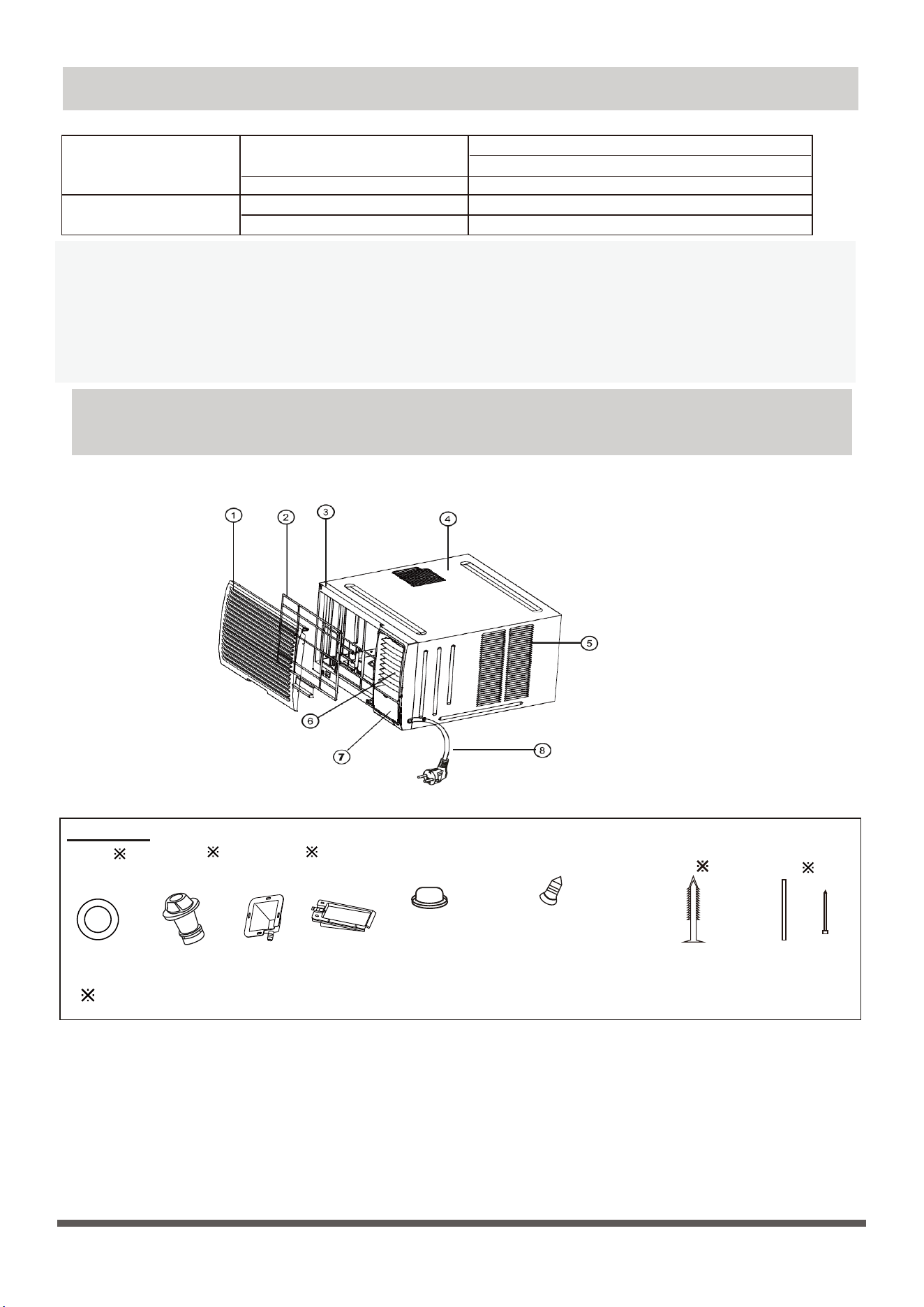
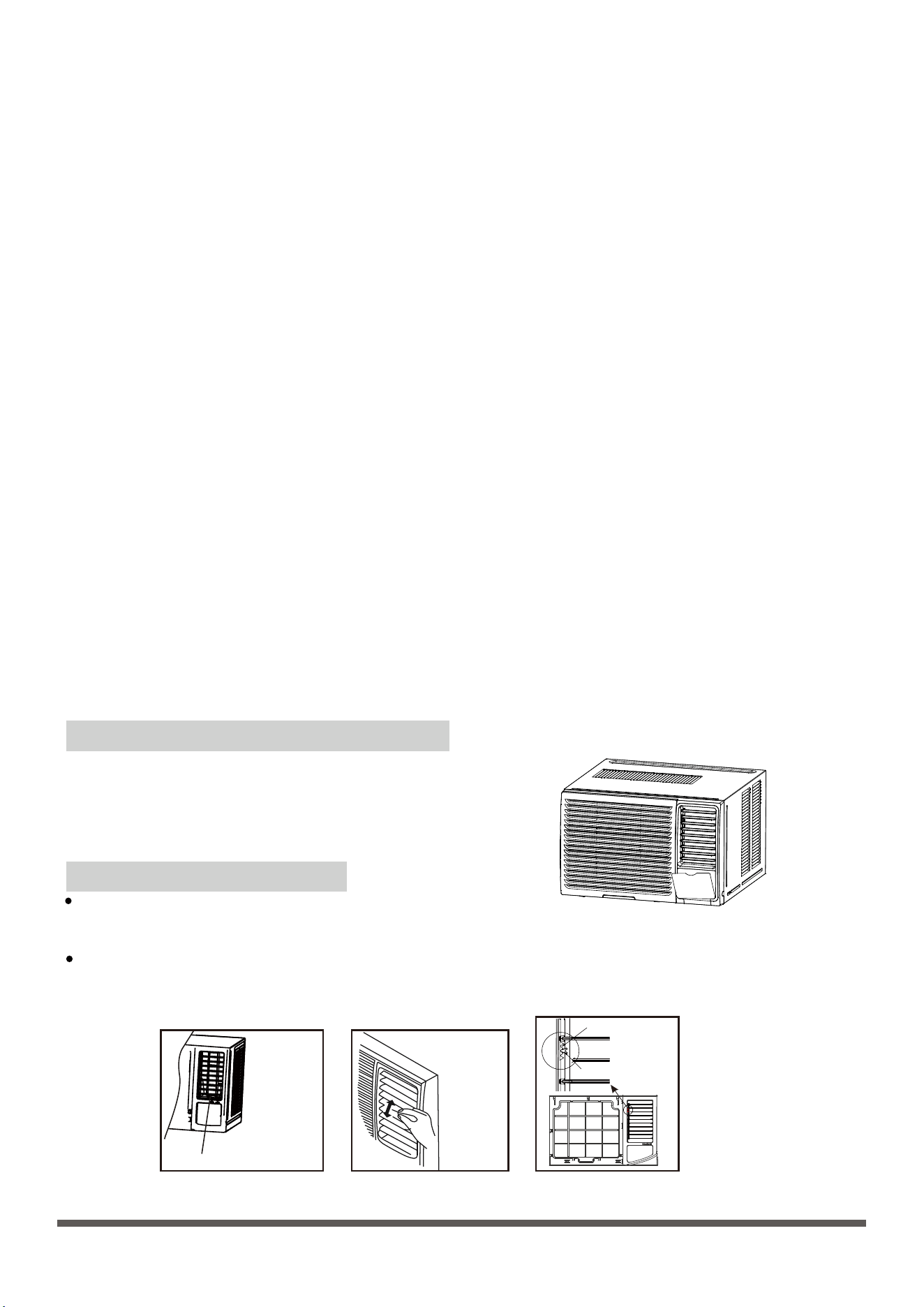
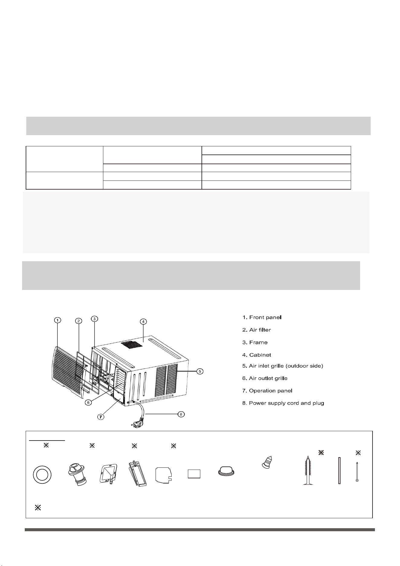
注意:不同型號有不同的前面板和機櫃。本手冊中的插圖僅用於說明。室內機的實際外形可能略有不同,請以實際外形為准。參考下
圖:
1. 前面板
2. 空氣篩檢程式
3. 框架
4. 機櫃
5. 進氣格柵(室外側)
6. 出風格柵
7. 操作旋鈕
8. 電源線
9. 控制台蓋(部分裝置)
10. 遙控器
密封件( )
(用於排水
接頭)
木螺釘(可
選)( )
PVC護套和
紮帶( )
1 - 2個(取決
於型號)
2個(對於某些裝
置,用於固定前面
板) 2個或4個(用
於安裝排水盤)
8個(取決於購買的
型號)
10
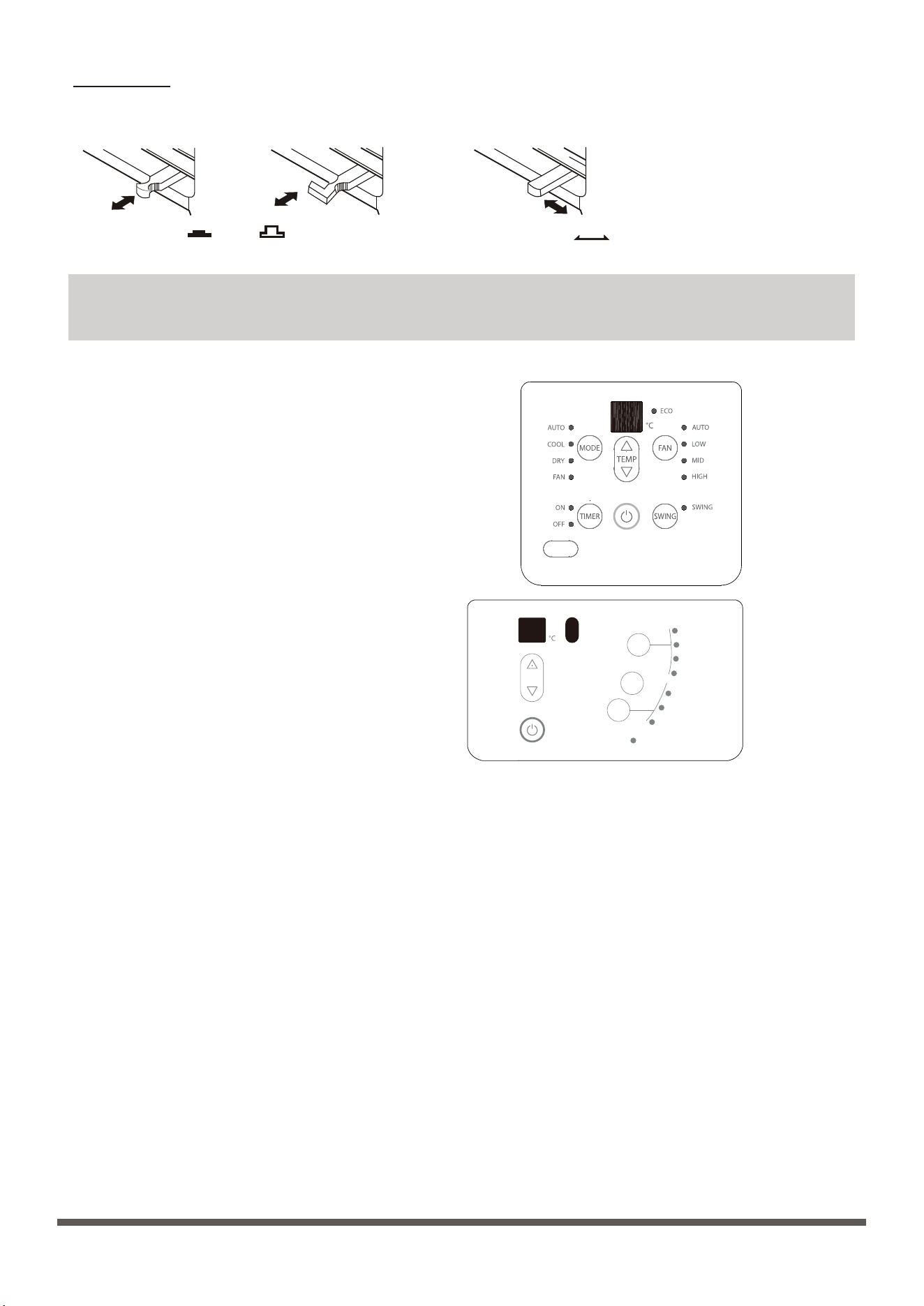
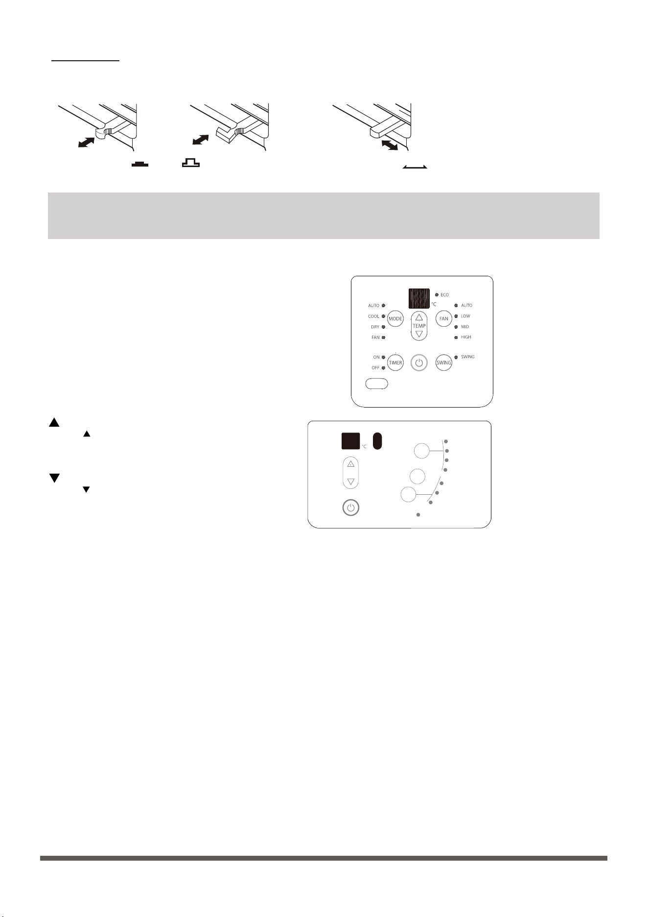
通風口控制
關閉
打開
關閉 通風口 打開
注意:並非所有裝置都有通風口控制。
操作說明
通風口控制位於控制旋鈕上方。不同型號的操作方法和外形可能有所不同(見下圖)。
為獲得最大製冷效率,請關閉通風口,從而使內部空氣迴圈。打開通風口排出不新鮮的空氣。
注意:不同型號有不同的操作面板。您購買的空調可能並不具備以下描述的所有功能。請檢查購買設備的操作面板。以下圖
形用於說明,請以實際外形為准。
注意:某些型號沒有中速功能和(或)自動模式功能和(或)
擺動功能。
電源:
按電源鍵打開/關閉設備。
模式:
按“模式”鍵選擇合適的操作模式。模式選擇將在自動、加熱
(單冷機型無此功能)、製冷、風扇和除濕之間交替。“模式
”選項旁的指示燈將亮起,標識所選模式。
除濕:(僅限部分型號)
此模式用於降低房間內的濕度。在此模式下,無法選擇風扇速度。
風扇電機以低速運行。保持門窗關閉可以獲得最佳除濕效果。
注意:在 抽濕模式下,您無法在某些型號上調節溫度。
製冷:
溫度設置可在17°C /16°C 至30°C /31°C之間調節。可以選擇所
需的風扇速度。
制熱:(僅限部分型號)
在加熱模式下,溫度設置可在17°C /16°C至30°C /31°C之間調節。
可以選擇所需的風扇速度。
自動:(僅限部分型號)
風扇電機在自動模式下保持中速。設備將根據實際溫度與所需室溫之間的溫差從風扇、製冷或加熱(僅適用於反向迴圈機型)中選擇適當的
操作模式。某些沒有中速的型號,風扇電機在自動模式下以高速運行。
注意:在自動模式下,您不能同時調整某些型號的溫度和風扇速度。
在自動模式下,您只是無法調整某些型號的風扇速度。
風扇模式:(僅限部分型號)
按“模式”鍵選擇風扇模式,您可以按“風扇”鍵選擇所需的風扇速度但不能調節溫度。
▲溫度增加設置:
按▲鍵增加設備的設定(運行)溫度。每次按下此鍵時,溫度會升高1 °C。最高設置30°C /31°C。
▼溫度降低設置:
按▼鍵降低設備的設定(運行)溫度。每次按下此鍵時,溫度會降低1 °C。最低設置17°C /16°C。
風扇:
按此鍵可啟動適當的風扇速度設置。每次按下此鍵都會在自動(僅限部分型號)、低,中(僅限部分型號)、高風扇速度選項之間交替。風
扇速度選項旁的指示燈將亮起,標識所選的風扇速度。
擺動:(僅限部分型號)
按“擺動”鍵啟動自動擺動功能。“擺動”鍵旁的指示燈將亮起,表明所選模式正在運行。垂直百葉將前後(左右)擺動自動交替吹掃空
氣,以實現舒適的製冷/加熱。要停止擺動功能,請再次按下“擺動”鍵,鍵旁的指示燈將熄滅。
3/4匹 / 1匹 / 1.5匹
2匹
TEMP
MODE
COOL
FAN
AU
DRY
TO
HIGH
MID
L
SLEEP MODE
OW
SWING
FAN
11
風向控制
操作面板蓋(部分機型)
水準氣流調節
對於帶手動控制杆的機型(手動)
對於帶操作面板蓋的裝置(參見右圖)
垂直氣流調節(手動)
1. 抓住操作蓋的頂部或左側並將其拉開。
2. 關閉操作蓋並再次按下直至其卡入鎖定位置。
請勿按壓或擺動打開的操作蓋。
手動控制杆
圖C
圖D
圖E
凹槽
凸塊
睡眠:
按住“擺動”鍵2秒鐘或使用遙控器啟動“睡眠”功能。按住“擺動”鍵2秒鐘或再次使用遙控器禁用“睡眠”功能。在製冷模式下,選擇“睡眠
”模式後,製冷溫度設定點每小時會增加1 °C。兩小時後,設定點將繼續保持該溫度,風扇電機將保持低速。在加熱模式下,選擇“睡眠”模式
後,加熱溫度設定點將每小時降低1 °C。兩小時後,設定點將繼續保持此溫度,風扇電機將保持低速。對於變頻式機型,新溫度將保持7小時,
然後設備退出睡眠模式並關閉。使用“睡眠”模式將減少噪音,營造舒適的睡眠環境。
注意:此功能在除濕和僅風扇運行時不可用。
增強功能(僅限部分型號)
在製冷/加熱(僅適用於採用電加熱器的機型)模式下,按遙控器上的增強按鈕,空調進入強力製冷/制熱運行。再按一次取消增強功能。
節能功能(僅限部分型號)
在製冷 模式下按遙控器的 節能 鍵進入節能模式。
LED顯示屏:
• 在僅風扇模式下顯示室溫,在其他模式下顯示設定溫度。
• 在計時器設置過程中顯示時間,10秒後系統將恢復顯示設定溫度。
顯示錯誤代碼:(變頻式)
E0:室內EEPROM錯誤;
E1:室內外通訊錯誤;
E3:室內風扇電機轉速失控;
E4:室溫感測器錯誤;
E5:蒸發器溫度感測器錯誤;
EC:製冷劑洩漏檢測;
F0:電流超載保護;
F1:室外溫度感測器錯誤;
F2:冷凝器溫度感測器錯誤;
注意:由於本機發生故障,本機可能會停止運行。 如果發生這種情況,顯示屏上可能會出現如下所示的錯誤代碼。請等待 10 分鐘,因為問題可
能會自行解決。 如果沒有,請斷開電源,然後重新連接。 打開設備。 如果問題仍然存在,請斷開電源並聯繫客戶服務。
F3:排氣溫度感測器錯誤;
F4:室外電動EE錯誤;
P0:IPM模組錯誤;
P1:電壓過高/過低保護;
P2:IPM高溫保護;
P3:室外溫度過低保護
(適用於製冷和加熱機型);
P4:壓縮機位置保護;
P7:室外IGBT感測器錯誤。
要調整水準氣流方向,用手輕輕向左或向右移動控制杆,直到獲得所需的水準氣流方向(見圖C)。
裝置運行時,用手調節百葉,改變垂直氣流方向。可以握住百葉並移動到所需位置,從而設置氣流的垂直角度(見圖D)。
有些機組的百葉連杆上裝有凸塊,可在機架左側的三個凹槽之間以0-15度的角度移動(見圖E)。
計時器:(僅限部分型號)
• 當設備開啟時,按下計時器按鈕將啟動自動停止程式,計時器關閉指示燈亮起。按向上或向下按鈕選擇所需時間。在10秒內再次按下計時器
按鈕,自動啟動程式啟動,計時器開啟指示燈亮起。按向上或向下按鈕選擇所需的自動啟動時間。
• 當設備關閉時,按下計時器按鈕啟動自動啟動程式,在10秒內再次按下將啟動自動停止程式。
• 按住向上或向下按鈕以0.5小時的增量更改自動時間,最多到10小時,然後以1小時的增量更改到24小時。控制器將倒計時剩餘時間,直到啟動。
• 如果在10秒內沒有操作,系統將自動恢復顯示之前的溫度設置。
• 任何時候打開或關閉設備或將計時器設置調整為0.0將取消自動啟動/停止計時器程式。
計時器:(僅限部分型號)
按“計時器”鍵啟動“自動啟動/自動停止”計時器功能。
自動啟動/停止程式可設置為0 ~ 12小時。每次按下“計時器”鍵都會以1小時的增量增加所選時間。
顯示錯誤代碼:(僅限部分型號)
錯誤代碼出現在室內機窗口顯示中,並以以下字母開頭:EH(xx)、EL(xx)、EC(xx)、PH(xx)、PL(xx)、PC(xx)。
12
重要
清潔空氣篩檢程式
冬季儲存
小心
切勿在沒有空氣篩檢程式的情況下運行空調,
因為灰塵/污垢顆粒會導致設備故障。
A型
B型
1
2
3
4
排水
後排水孔
後排水孔
排水接頭
密封件
橡膠塞
螺釘
排水盤
排水口
橡膠塞
橡膠塞
底排水孔
底部排水孔
底部排水
後排水
不排水
清潔或維護之前
在清潔或維護之前,請務必關閉空調系統並斷開其電源。
保養和維護
清潔設備
機櫃和前面板可用無油布擦拭或用布蘸溫水與溫和洗碗液溶液清洗。徹底沖洗並擦乾。
•
請勿在空調附近使用油漆或髮膠等易燃噴霧劑。
•
請勿使用苯、酒精、汽油、酸、油漆稀釋劑、拋光粉或其他溶劑清潔本機,否則可能會損壞設備。
•
請勿使用超過50 °C(122 °F)的水清潔前面板,否則會導致面板變形或變色。
•
控制器內部或周圍過多的水可能會損壞空調。在擦拭乾淨之前,一定要擰乾布上多餘的水。
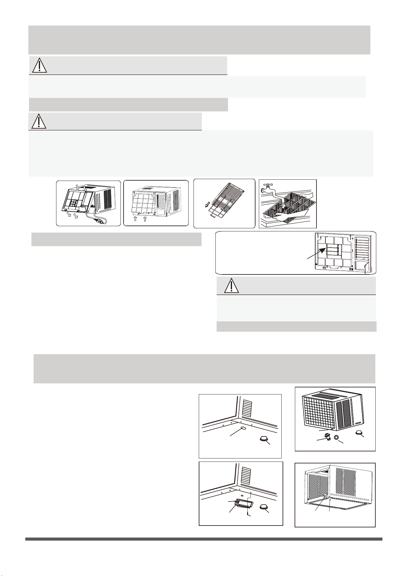
空氣篩檢程式堵塞會降低設備的製冷效率並增加運行噪音。確保在頻繁
操作期間每兩周(或根據需要)清潔一次篩檢程式。
1. 握住前面板下方的插槽,向外提起,取下前面板。
2. 捏住空氣篩檢程式下方的把手,使空氣篩檢程式呈拱形,從卡槽中從
下往上取出(A型)。抓住篩檢程式的把手,然後將其向下滑動以取下
篩檢程式(B型)。
3. 用溫肥皂水清潔篩檢程式。水溫應低於40 °C(104 °F)以防止篩檢程
式變形。
4. 如果篩檢程式帶有小型空氣清新篩檢程式,請使用手持真空吸塵器清
潔此篩檢程式。
5. 用清水沖洗空氣篩檢程式,然後甩掉多餘的水。
6. 在陰涼乾燥處晾乾,避免陽光直射。
如果篩檢程式有一個小的空氣清新篩
檢程式(可選),可安裝在四個位置
中的任何一個。用手持真空吸塵器清
潔篩檢程式。
如果要在冬季存放空調,請按照安裝說明小心地將其從窗戶上
取下。用塑膠蓋住或將其放回原包裝箱中。
冷凝水的處理方法如下:
底部排水(僅適用於設計有底部排水孔的裝置。)
- 取下機櫃底部的橡膠塞(如果有)
- 從附件中取出排水盤和螺釘。
- 用螺釘將排水盤固定在機櫃底部。
- 將延長排水軟管(當地購買)連接到排水盤的出口。
注意:底部排水會輕微影響製冷性能,但可以減少因噴灑
冷凝水而產生的噪音。對於泵加熱,必須選擇底部排水。
後排水
- 將密封件安裝到排水接頭上(附件提供)。
- 將排水接頭插入後排水孔,將其旋轉90°以貼合。
- 將延長排水軟管(根據安裝長度要求在當地購買)連接
到排水接頭。
- 確保用橡膠塞堵住底部排水孔。
注意:後排水會輕微影響製冷性能,但可以減少因噴灑冷
凝水而產生的噪音。
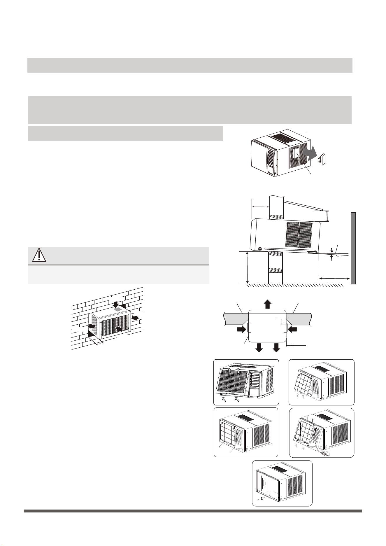
圖5A - A型
13
第1步:選擇最佳位置
安裝前
安裝說明
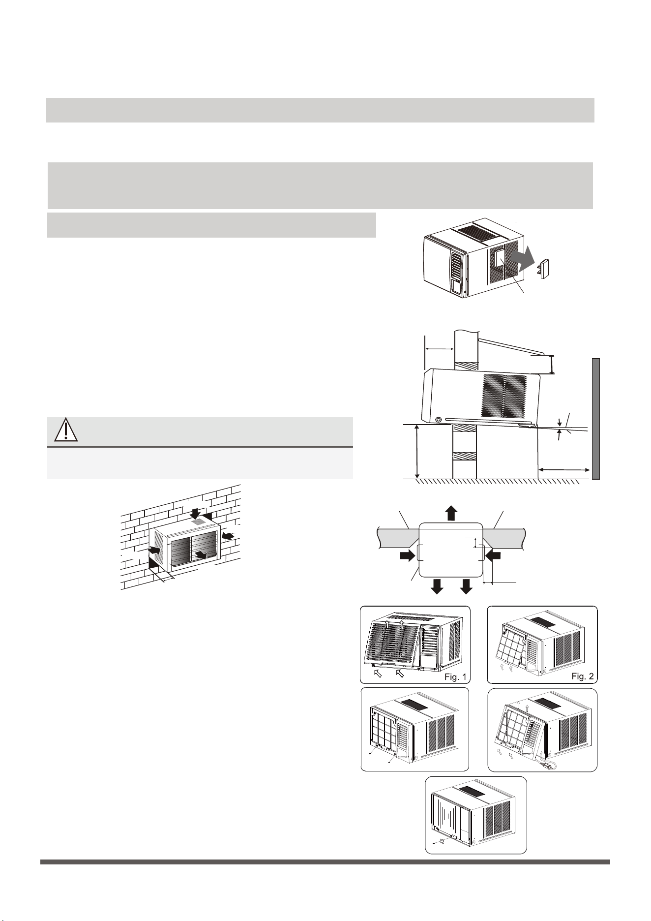
小心:安裝前,請從紙箱內取出所有包裝以及放入側百葉
的所有外掛程式。
小心
機櫃的所有側百葉都必須暴露在結構的外部。
取出放置在側百葉中
的外掛程式
300毫米以上
800毫米
以上
遮陽篷
柵欄
室外側
室內側
牆
75~150cm
500毫米以上
水準
設備
約5~7毫米
選項A
進風
進風
進風
出風
至少100毫米
至少500毫米
選項 B
45°磚切割為百葉
留出空間
正面
45°磚切割為百葉
留出空間
磚牆 磚牆
進風
圖1 圖2
圖3 圖4
100毫米
出風
100毫米
進風
百葉
產品注意事項
•
•
額定製冷性能是在不排水狀態下測試的。
確保在使用橡膠塞和接頭時周圍不會漏水。如果發現洩漏,請密封。
不排水
如果選擇製冷時不排水,則應用橡膠塞堵住機組底部和後排水孔。冷凝水噴到冷凝器,提高製冷性能。
注意:選擇不排水時,空調將具有完美的製冷效率,但可能會因噴出冷凝水而產生較大的噪音。如果您對噪音敏感,請不要選
擇該選項。
第2步:取下前面板和空氣篩檢程式
1. 從包裝中取出空調。
2. 握住前面板下方的插槽,向外提起,取下前面板(見圖1)。
3. 抓住篩檢程式末端的拉環,將其向上提起,然後朝向自己拉,將篩
檢程式拉出(見圖2)。
第3步:取下機架
1. 拆下機架底部的兩顆螺釘(見圖3)。
2. 斷開耦合器插頭並確保不會干擾溫度感測器電纜。握住機架的左下
側,將其向上提起以解鎖下側,然後朝向自己將其取下(見圖4)。
注意:對於某些設備,前面板和機架不安裝在設備背面,不需要第2步
和第3步。
第4步:取下機櫃
注意:根據機型不同,機櫃拆卸略有差異。
A型:
1. 取下固定主機殼固定支架的一顆螺釘,然後取下主機殼固定支架,
如圖5A所示。
2. 抓住主機殼上的把手,小心地將空調滑出機櫃。(見圖6)
1. 為避免振動和噪音,請確保設備安裝牢固。
2. 將設備安裝在陽光不會直接照射到的地方。如果設備受到陽光直射,請
搭建遮陽篷為機櫃遮陰。
3. 櫃體背面50釐米內不得有柵欄、牆壁等障礙物,以免冷凝器散熱。外界
空氣限制會大大降低空調的製冷和制熱效率。
4. 將設備向外稍微傾斜向下安裝,以免冷凝水洩漏到室內(約5~7毫
米)。
5. 將設備底部安裝在高於地面75~150釐米的位置。
6. 電源線必須連接到獨立的電路上。黃/綠線必須接地。
第6步:將設備安裝到機櫃中
圖10
圖11
C型:
D型:
第5步:安裝機櫃
排水盤
首選安裝到木框架牆、隔斷或窗戶
空調平衡點外支撐架
或者使用如下所示的支架
排水盤
無法提供外部支撐時的替代安裝方法
堅固的木框架
木框架牆或隔斷
確保百葉完全
在牆外
固定支架
(每側一個)
木支架
圖5B - B型
圖5C - C型
圖6
圖7
牆
機櫃
螺釘
圖5D - D型
14
圖8
圖9
B型:
1. 取下固定主機殼固定支架的一顆螺釘,然後取下主機殼固定支架。取
下機櫃背面的兩顆螺釘,如圖5B所示。
2. 抓住主機殼上的把手,小心地將空調滑出機櫃。(見圖6)
1. 如圖5C所示,取下位於機櫃兩側和背面的四顆螺釘。
2. 抓住主機殼上的把手,小心地將空調滑出機櫃。(見圖6)
1. 取下固定主機殼固定支架的一顆螺釘,然後取下主機殼固定支架。
(見圖5D)
2. 如圖5D所示,取下機櫃兩側和背面的四顆螺釘。
3. 抓住主機殼上的把手,小心地將空調滑出機櫃。(見圖6)
注意:裝置可由下方的實心機架支撐,或由實心頭頂支架上的
吊架支撐(需單獨購買,請聯繫經銷商)。
1. 需要排水時,將放水塞安裝在底盤上。
2. 準備牆上的孔,使機櫃底部得到很好的支撐,頂部間隙最
小,進風百葉的間隙如上一頁所示(圖選項A和B)。應密封
從外部到腔體的孔。機櫃應向後傾斜約5~7毫米,以便將操
作過程中形成的水排出。
3. 將機櫃安裝到牆上並固定。確保泡沫密封沒有損壞。對內部
和外部周圍的縫隙加薄片、密封或填充,以提供良好的外觀
和抵禦天氣、昆蟲和齧齒動物的保護。(見圖7)
1. 將設備滑入機櫃,直到牢牢靠在機櫃後部。需要注意確保機櫃上的泡沫密封條保持原位(見圖8)。
2. 將空調連接到電源並將多餘的電線放置在空調底座下方。
3. 將主機殼固定支架卡入機櫃底部導軌,並用提供的螺釘固定在底座上。
第7步:安裝框架
1. 鉤住機架的上邊緣,然後連接耦合器插頭並確保不會干擾溫度感
測器電纜(見圖9)。
2. 按壓機架的兩側和下邊緣,用兩顆螺釘固定在機架底部。
(見圖10)
第8步:安裝空氣篩檢程式和前面板
1. 將空氣篩檢程式從上向下插入機架的插槽中。(見圖2)
2. 將前面板掛在機架的搭扣上,然後將前面板按入機架的插槽,直
到聽到哢嗒聲(見圖11)。
3. 開啟設備。檢查裝置運行情況,並在安裝後檢查振動。
4. 將排水盤安裝到機櫃上,並在需要時將排水軟管連接到合適的位
置。
外牆框架或楣板周圍加
薄片或密封
裝置四周是堅
固的木框架
木框架牆或
隔斷
外牆框架或楣板周圍加
薄片或密封
常見問題
故障排除
安全須知
15
圖a
圖b
圖c
圖d
圖e
圖f
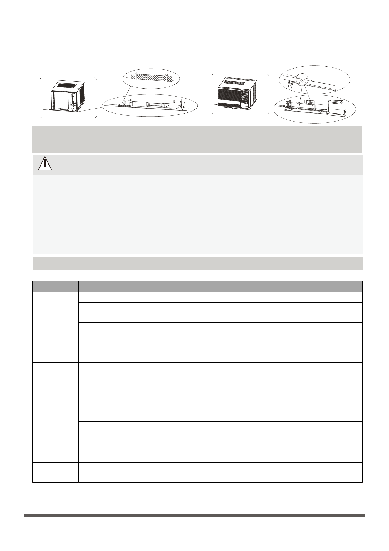
注意:對於電源線在左側的裝置,請執行以下步驟:
1. 將電源線向左側拉直(見圖a和b)。
2. 用紮線帶將電源線上的PVC保護套纏繞在孔位(見圖c)。
3. 將電源線綁在機架上(見圖d和e)(僅適用於機身尺寸為600 *380 *560毫米的裝置)。
4. 按照上述第6步和第7步安裝機架和前面板。
如果出現以下任何一種情況,請立即關閉設備!
•
電源線損壞或異常發熱
•
有燒焦的氣味
•
設備發出響亮或異常的聲音
•
電源保險絲熔斷或斷路器頻繁跳閘
•
水或其他物體落入或落出本機
請勿試圖自己解決這些問題!立即聯繫授權服務提供者!
問題 可能原因 該怎麼辦
空調插頭斷開。 - 確保空調插頭完全插入插座並打開。
保險絲熔斷/斷路器跳閘
。
- 檢查房屋保險絲/斷路器盒並更換保險絲或重置斷路器。
電源故障。
- 如果發生電源故障,請關閉電源並斷開/拔下電源線。 恢復
供電後,重新連接(插上)電源線,接通電源,等待3分鐘重
新啟動空調,防止壓縮機過載跳閘。
氣流受到限制。 - 確保沒有窗簾、百葉窗或家具擋住了空調的前部。
空氣過濾器骯髒。
- 至少每 2 周清潔一次過濾器。
- 請參閱操作說明部分。
房間可能很熱。 - 當你第一次打開空調時需要留出時間讓房間冷卻下來
冷空氣正在逃逸。
- 檢查打開的壁爐門窗和冷空氣正在逃跑。 冷空氣返回。
- 將空調出風口設置為關閉位置
冷卻盤管結冰了。
- 請參閱下面的空調凍結。
空調結冰
冰會阻擋氣流並阻止空調
冷卻房間。
- 將風扇設置為 MID 或 HIGH,直到冰融化。
空調不啟動
空調沒有像
應有的那樣
冷卻
設備尺寸: 選擇正確的電纜尺寸
型號(But/h)
5000~6000
445x320x415
450x346x535
450x346x535
675x350x450.6
675x350x450.6
560x400x640
600x380x560
780x428x660
780x428x660
7000~9000
9000~12000
15000~24000
機身尺寸(寬×高×深)(毫米)
規格
電器額定電流(A) 標稱截面積(平方毫米)
0.75
1
1.5
2.5
4
6
16
注意:針對不同的定制需求,面板深度
可能略有不同,因此“深”僅供參考。
所需的電源線、信號線、保險絲和開關的尺寸由設備的最大電流決定。最大電流顯示在設
備側面板的銘牌上。請參閱此銘牌以選擇正確的電纜、保險絲或開關。
導體的最小標稱截面積:
> 3並且≤ 6
> 6並且≤ 10
> 10並且≤ 16
> 16並且≤ 25
> 25並且≤ 32
> 32並且≤ 40

CW002UI-F(E)RN8
設計和規格如有更改,恕不另行通知。詳情請諮詢銷售機構或製造商。手冊的任何
更新都會上傳到服務網站,請檢查最新版本。
IMPORTANT NOTE:
Read this manual carefully before installing
or operating your new air conditioning
unit. Make sure to save this manual for
future reference.
Please check the applicable models, technical
data from the nameplate pasted on the unit.
TOSHIBA Air Conditioner(Window type)
Owner’s Manual
Model
RAC-07G3CVRGR-HK
RAC-09G3CVRGR-HK
RAC-12G3CVRGR-HK
RAC-18G3CVRGR-HK
RAC-07G3CVRG-HK RAC-07G3CVG-HK
RAC-09G3CVG-HK
RAC-12G3CVG-HK
RAC-18G3CVG-HK
Precautions
Read Safety Precautions Before Operation and Installation
Incorrect installation due to ignore of instructions can cause serious damage or injury.
Safety Precautions
WARNING
1.
Installation
- Where refrigerant pipes shall be compliance with national gas regulations.
- That mechanical connections shall be accessible for maintenance purposes.
- In cases that require mechanical ventilation, ventilation openings shall be kept clear of obstruction.
- When disposing of the product is used, be based on national regulations, properly processed.
2.
Servicing
- Any person who is involved with working on or breaking into a refrigerant circuit should hold
a current valid certificate from an industry-accredited assessment authority, which
authorises their competence to handle refrigerants safely in accordance with an industry
recognised assessment specification.
3.
Maintenance and repair requires the assistance of other skilled personnel shall be carried out
under the supervision of the person competent in the use of flammable refrigerants.
4.
Do not use means to accelerate the defrosting process or to clean, other than those
recommended by the manufacturer.
5.
The appliance shall be stored in a room without continuously operating ignition sources
(for example: open flames,an operating gas appliance or an operating electric heater)
6.
Be more careful that foreign matter(oil, water,etc) does not enter the piping. Also, when storing
the piping, securely seal the opening by pinching, taping, etc.
7.
Do not pierce or burn.
8.
Be aware that refrigerants may not contain an odour.
9.
All working procedure that affects safety means shall only be carried by competent persons.
10.
Appliance shall be stored in a well -ventilated area where the room size corresponds to the
room area as specifiec for operation.
11.
The appliance shall be stored so as to prevent mechanical damage from occurring.
12.
13.
The installation height shall not lower than 0.75m.
- Installation must be performed by an authorized dealer or professionally trained technician..
The appliance is using mildly flammable refrigerant R32 and tested to comply with IEC
60335-2-40. There is no minimum room area requirement for the appliance.
CAUTION
CAUTION
CAUTION
WARNING
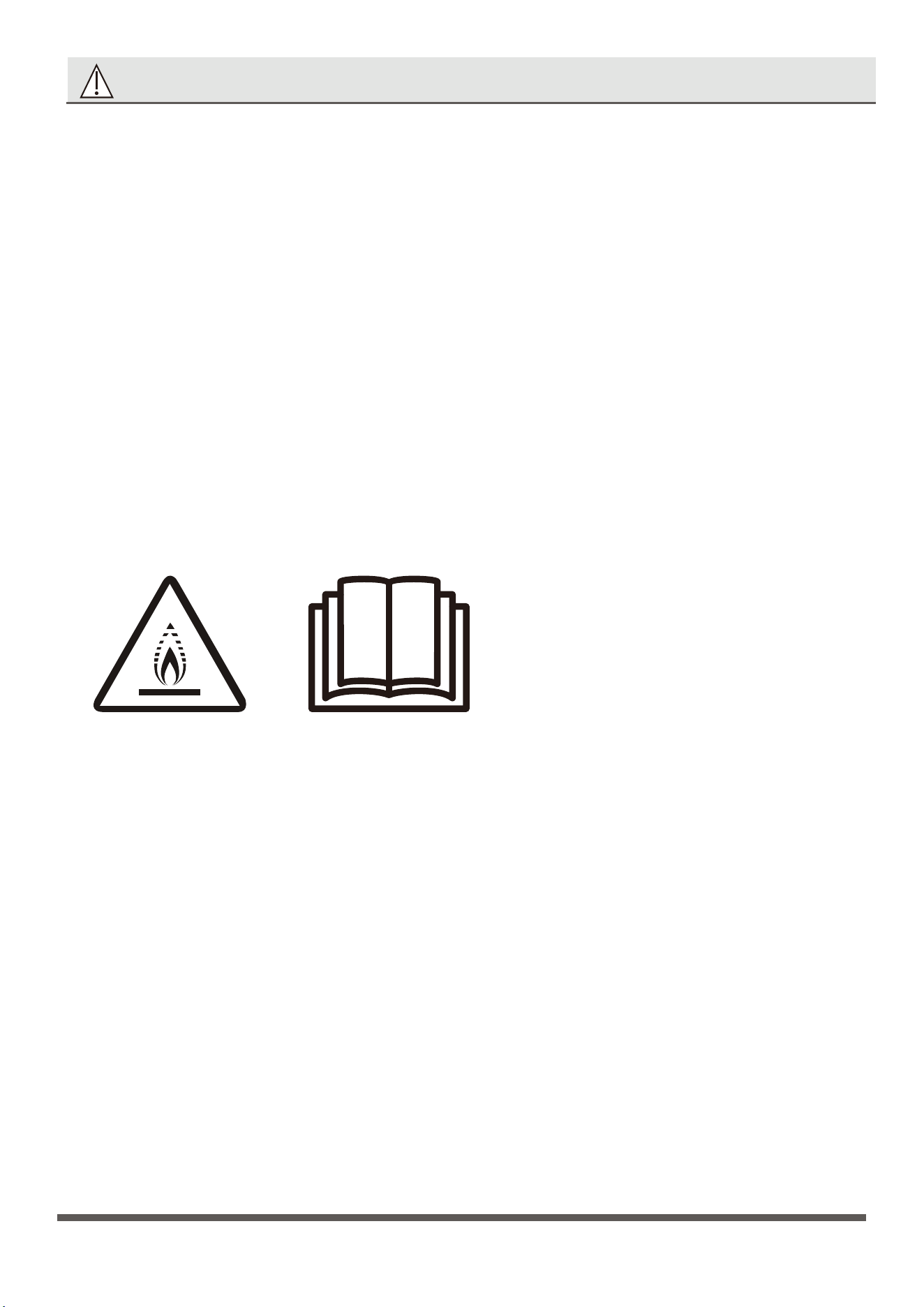
This symbol shows that this appliance used a mildly flammable refrigerant.
If the refrigerant is leaked and exposed to an external ignition source,
there is a risk of fire.
This symbol shows that the operation manual should be read carefully.
This symbol shows that information is available such as the operating
manual or installation manual.
This symbol shows that a service personnel should be handling this
equipment with reference to the installation manual.
Explanation of symbols displayed on the unit
1. Transport of equipment containing flammable refrigerants
Compliance with the transport regulations
2. Marking of equipment using signs
Compliance with local regulations
3. Disposal of equipment using flammable refrigerants
Compliance with national regulations
4. Storage of equipment/appliances
The storage of equipment should be in accordance with the manufacturer’s instructions.
5. Storage of packed (unsold) equipment
Storage package protection should be constructed such that mechanical damage to the
equipment inside the package will not cause a leak of the refrigerant charge.
The maximum number of pieces of equipment permitted to be stored together will be
determined by local regulations.
Transportation, marking and storage for units

Warning
.................................................................................................
Unit Parts Identification .............
............................................................
Operation Instructions........................................................................
Care and Maintenance........................................................................
Water Drainage ..........................
.............................................................
Installation Instructions .....................................................................
Troubleshooting...................................................................................
Specifications ......................................................................................
Table of Contents
European Disposal Guidelines
This appliance contains refrigerant and other potentially hazardous materials. When disposing of this appliance, the
law requires special collection and treatment. Do not dispose of this product as household waste or unsorted muni-
cipal waste.
When disposing of this appliance, you have the following options:
Dispose of the appliance at designated municipal electronic waste collection facility.
When buying a new appliance, the retailer will take back the old appliance free of charge.
The manufactuer will take back the old appliance free of charge.
Sell the appliance to certified scrap metal dealers.
•
Special notice
Disposing of this appliance in the forest or other natural surroundings endangers your health and is bad for the envi-
ronment. Hazardous substances may leak into the ground water and enter the food chain.
Correct Disposal of This Product
(Waste Electrical & Electronic Equipment)
This marking shown on the product or its literature, indicates that waste electrical and
eletrical equipment should not be mixed with general household waste.
03
09
10
11
12
13
15
16
•
•
•
3
Read Before Operation and Installation
Incorrect installation due to ignoring instructions can cause serious damage or injury.
The seriousness of potential damage or injuries is classified as either a WARNING or CAUTION.
WARNING
This appliance is not intended for use by persons(including children) with reduced physical, sensory or mental capabilities,
or lack of experience and knowledge, unless they have been given supervision or instruction concerning use of the appliance
by a person responsible for their safety. Children should be supervised to ensure that they do not play with the appliance.
WARNINGS FOR PRODUCT USE
•
If an abnormal situation arises (like a burning smell), immediately turn off the unit and disconnect the power. Call your
dealer for instructions to avoid electric shock, fire or injury.
•
Do not
insert fingers, rods or other objects into the air inlet or outlet. This may cause injury, since the fan may be rotat-
ing at high speeds.
•
Do not
use flammable sprays such as hair spray, lacquer or paint near the unit. This may cause fire or combustion.
•
Do not
operate the air conditioner in places near or around combustible gases. Emitted gas may collect around the
unit and cause explosion.
•
Do not
•
•
Do not
expose your body directly to cool air for a prolonged period of time.
•
•
•
•
•
If the air conditioner is used together with burners or other heating devices, thoroughly ventilate the room to avoid
oxygen de
ciency.
Warning
Do not
allow children to play with the air conditioner. Children must be supervised around the unit at all times.
operate your air conditioner in a wet room such as a bathroom or laundry room. Too much exposure to water
can cause electrical components to short circuit.
In certain functional environments, such as kitchens, server rooms, etc., the use of specially designed air-conditioning
units is highly recommended.
Unplug the unit or disconnect the power supply to the unit if strange sounds, smell, or smokecomes from it.
To further optimize the performance of your unit, keep doors and windows closed during operation.
Pay attention when unpacking and installing. Sharp edges could cause injury.
•
Do not
clean the air conditioner with combustible cleaning agents. Combustible cleaning agents can cause fire or
deformation.
CLEANING AND MAINTENANCE WARNINGS
•
Turn off the device and disconnect the power before cleaning. Failure to do so can cause electrical shock.
•
Do not
clean the air conditioner with excessive amounts of water.
CAUTION
•
Turn off the air conditioner and disconnect the power if you are not going to use it for a long time.
•
Turn off and unplug the unit during storms.
•
Make sure that water condensation can drain unhindered from the unit.
•
Do not
operate the air conditioner with wet hands. This may cause electric shock.
•
Do not
use device for any other purpose than its intended use.
•
Do not
climb onto or place objects on top of the outdoor unit.
•
Do not
allow the air conditioner to operate for long periods of time with doors or windows open, or if the humidity is very high.
WARNING
This symbol indicates the possibility
of personnel injury or loss of life.
CAUTION
This symbol indicates the possibility of
property damage or serious consequences.
•
This appliance is using R32 mildly flammable refrigerant.
•
4
ELECTRICAL WARNINGS
•
Only use the specified power cord. If the power cord is damaged, it must be replaced by the manufacturer, its service
agent or similarly qualified persons in order to avoid a hazard.
Keep power plug clean. Remove any dust or grime that accumulates on or around the plug. Dirty plugs can cause fire
or electric shock.
Do not
pull power cord to unplug unit. Hold the plug firmly and pull it from the outlet. Pulling directly on the cord can
damage it, which can lead to fire or electric shock.
Do not
modify the length of the power supply cord or use an extension cord to power the unit.
Do not
share the electrical outlet with other appliances. Improper or insufficient power supply can cause fire or electrical
shock.Always install circuit breaker and a dedicated power circuit.
Do not
use the socket if it is loose or damaged.
Do not
place heavy object on the power cord and ensure that the cord is not compressed.
There is danger of fire or electric shock.
If water enters the unit, turn the unit off at the power outlet and switch off the circuit breaker.
Isolate supply by taking the power-plug out or disconnect the power supply to the unit, contacta qualified service
technician.
The product must be properly grounded at the time of installation, or electrical shock may occur.
For all electrical work, follow all local and national wiring standards, regulations, and the Electrical Connection Diagram
located on the top panel of the unit.
If connecting power to fixed wiring, an all-pole disconnection device which has at least 3mm clearances in all poles,
and have a leakage current that may exceed 10mA, the residual current device(RCD) having a rated residual operating
current not exceeding 30mA, and disconnection must be incorporated in the fixed wiring in accordance with the wiring
rules.
This unit is earthed through the power cord, make sure that the unit is correctly grounded. The wall outlet(Air-break
switch) should be provided with reliable earth wire.
The unit should be provided with an individual circuit and the circuit breaker/fuse rating should be the same as that
of the power cord and wall outlet. Power cord conductors are distinguished according to the color as shown in Wiring
Diagram located on the top of the machine.
WARNINGS FOR PRODUCT INSTALLATION
1. Installation must be performed by an authorized dealer or professionally trained technician. Defective installation can
cause water leakage, electrical shock, or fire.
2. Installation must be performed according to the installation instructions. Improper installation can cause water leakage,
electrical shock, or fire. (In North America,installation must be performed in accordance with the requirement of NEC
and CEC by authorized personnel only.)
3. Contact an authorized service technician for repair or maintenance of this unit. This appliance shall be installed in acc-
ordance with national wiring regulations.
4. Only use the included accessories, parts, and specified parts for installation. Using non-standard parts can cause water
leakage, electrical shock, fire, and can cause the unit to fail.
5. Install the unit in a firm location that can support the unit’s weight. If the chosen location cannot support the unit’s
weight, or the installation is not done properly, the unit may drop and cause serious injury and damage.
6. Install drainage piping according to the instructions in this manual. Improper drainage may cause water damage to your
home and property.
7. For units that have an auxiliary electric heater, do not install the unit within 1 meter (3 feet) of any combustible materials.
8.
Do not
install the unit in a location that may be exposed to combustible gas leaks. If combustible gas accumulates aro-
und the unit, it may cause fire.
9.
Do not
turn on the power until all work has been completed.
10. When moving or relocating the air conditioner, consult experienced service technicians for disconnection and reinsta-
llation of the unit.
11. How to install the appliance to its support, please read the information for details in "Installation instructions" section.
TAKE NOTE OF FUSE SPECIFICATIONS
Wall outlet
Air-break switch
The air conditioner’s circuit board (PCB) is designed with a fuse to provide
overcurrent protection. The specifications of the fuse are printed on the circuit board,
such as 220V.
•
•
•
•
•
•
•
•
•
•
•
Warning: low burning
velocity material
(For R32 models apply to
IEC60335-2-40:2018)
5
WARNING for Using R32 Refrigerant
-Do not use means to accelerate the defrosting process or to clean, other than those recommended by the manufacturer.
-The appliance shall be stored in a room without continuously operating ignition sources (for example: open flames, an
operating gas appliance) and ignition sourcesor (for example:an operating electric heater) close to the appliance. The ap-
pliance shall be stored in a room without continuously operating ignition sources (for example: open flames, an operating
gas appliance or an operating electric heater).
-Do not pierce or burn.
-Be aware that the refrigerants may not contain an odour.
-Compliance with national gas regulations shall be observed.
-Keep ventilation openings clear of obstruction.
-The appliance shall be stored so as to prevent mechanical damage from occurring.
-A warning that the appliance shall be stored in a well-ventilated area where the room size corresponds to the room area
as specified for operation.
-Any person who is involved with working on or breaking into a refrigerant circuit should hold a current valid certificate
from an industry-accredited assessment authority, which authorises their competence to handle refrigerants safely in acc-
ordance with an industry recognised assessment specification.
-Servicing shall only be performed as recommended by the equipment manufacturer. Maintenance and repair requiring
the assistance of other skilled personnel shall be carried out under the supervision of the person competent in the use of
flammable refrigerants.
-Please follow the instruction carefully to handle, install, clear, service the air conditioner to avoid any damage or hazard.
mildly Flammable Refrigerant R32 is used within air conditioner. When maintaining or disposing the air conditioner, the
refrigerant (R32) shall be recovered properly, shall not discharge to air directly.
-No any open fire or device like switch which may generate spark/arcing shall be around air conditioner to avoid causing
ignition of the flammable refrigerant used.Please follow the instruction carefully to store or maintain the air conditioner to
prevent mechanical damage from occurring.
-Mildly flammable refrigerant is used in air conditioner. Please follow the instruction carefully to avoid any hazard.
IMPORTANT NOTE:Read this manual
carefully before installing or operating
your new air conditioning unit.
6
1.Transport of equipment containing flammable refrigerants
See transport regulations
2.Marking of equipment using signs
See local regulations
3.Disposal of equipment using flammable refrigerants
See national regulations.
4.Storage of equipment/appliances
The storage of equipment should be in accordance with the manufacturer's instructions.
5.Storage of packed (unsold) equipment
Storage package protection should be constructed such that mechanical damage to the equipment inside the package
will not cause a leak of the refrigerant charge.The maximum number of pieces of equipment permitted to be stored
together will be determined by local regulations.
6.Information on servicing
1)Checks to the area
Prior to beginning work on systems containing flammable refrigerants, safety checks are necessary to ensure that the
risk of ignition is minimised. For repair to the refrigerating system, the following precautions shall be complied with
prior to conducting work on the system.
2)Work procedure
Work shall be undertaken under a controlled procedure so as to minimise the risk of a flammable gas or vapour being
present while the work is being performed.
3)General work area
All maintenance staff and others working in the local area shall be instructed on the nature of work being carried out.
Work in confined spaces shall be avoided. The area around the workspace shall be sectioned off. Ensure that the con-
ditions within the area have been made safe by control of flammable material.
4)Checking for presence of refrigerant
The area shall be checked with an appropriate refrigerant detector prior to and during work, to ensure the technician is
aware of potentially flammable atmospheres. Ensure that the leak detection equipment being used is suitable for use
with flammable refrigerants, i.e. non-sparking, adequately sealed or intrinsically safe.
5)Presence of fire extinguisher
If any hot work is to be conducted on the refrigeration equipment or any associated parts,appropriate fire extinguishing
equipment shall be available to hand. Have a dry powder or CO2 fire extinguisher adjacent to the charging area.
6)No ignition sources
No person carrying out work in relation to a refrigeration system which involves exposing any pipe work that contains
or has contained flammable refrigerant shall use any sources of ignition in such a manner that it may lead to the risk of
fire or explosion. All possible ignition sources, including cigarette smoking, should be kept sufficiently far away from the
site of installation, repairing, removing and disposal, during which flammable refrigerant can possibly be released to the
surrounding space. Prior to work taking place, the area around the equipment is to be surveyed to make sure that there
are no flammable hazards or ignition risks. No Smoking signs shall be displayed.
7)Ventilated area
Ensure that the area is in the open or that it is adequately ventilated before breaking into the system or conducting any
hot work. A degree of ventilation shall continue during the period that the work is carried out. The ventilation should
safely disperse any released refrigerant and preferably expel it externally into the atmosphere.
8)Checks to the refrigeration equipment
Where electrical components are being changed, they shall be fit for the purpose and to the correct specification. At all
times the manufacturer's maintenance and service guidelines shall be followed. If in doubt consult the manufacturer's
technical department for assistance. The following checks shall be applied to installations using flammable refrigerants:
The charge size is in accordance with the room size within which the refrigerant containing parts are installed;
The ventilation machinery and outlets are operating adequately and are not obstructed;
If an indirect refrigerating circuit is being used, the secondary circuit shall be checked for the presence of refrigerant;
Marking to the equipment continues to be visible and legible. Markings and signs that are illegible shall be corrected;
Refrigeration pipe or components are installed in a position where they are unlikely to be exposed to any substance
which may corrode refrigerant containing components, unless the components are constructed of materials which are
inherently resistant to being corroded or are suitably protected against being so corroded.
9)Checks to electrical devices
WARNING
This symbol shows that this appliance
used a mildly flammable refrigerant.
If the refrigerant is leaked and exposed
to an external ignition source,there is
a risk of fire.
CAUTION
This symbol shows that the operation
manual should be read carefully.
CAUTION
This symbol shows that a service
personnel should be handling this
equipment with reference to the
installation manual.
CAUTION
This symbol shows that information
is available such as the operating
manual or installation manual.
Explanation of symbols displayed on the unit(For the unit adopts R32 Refrigerant only):

7
Repair and maintenance to electrical components shall include initial safety checks and component inspection proced-
ures. If a fault exists that could compromise safety, then no electrical supply shall be connected to the circuit until it is
satisfactorily dealt with. If the fault cannot be corrected immediately but it is necessary to continue operation, an adeq-
uate temporary solution shall be used. This shall be reported to the owner of the equipment so all parties are advised.
Initial safety checks shall include:
That capacitors are discharged: this shall be done in a safe manner to avoid possibility of sparking;
That there no live electrical components and wiring are exposed while charging, recovering or purging the system;
That there is continuity of earth bonding.
7.Repairs to sealed components
1)During repairs to sealed components, all electrical supplies shall be disconnected from the equipment being worked upon
prior to any removal of sealed covers, etc. If it isabsolutely necessary to have an electrical supply to equipment during ser-
vicing, then a permanently operating form of leak detection shall be located at the most critical point to warn of a poten-
tially hazardous situation.
2)Particular attention shall be paid to the following to ensure that by working on electrical components, the casing is not
altered in such a way that the level of protection is affected. This shall include damage to cables, excessive number of
connections, terminals not made to original specification, damage to seals, incorrect fitting of glands, etc.
Ensure that apparatus is mounted securely.
Ensure that seals or sealing materials have not degraded such that they no longer serve the purpose of preventing the ingr-
ess of flammable atmospheres. Replacement parts shall be in accordance with the manufacturer's specifications.
NOTE: The use of silicon sealant may inhibit the effectiveness of some types of leak detection equipment. Intrinsically safe
components do not have to be isolated prior to working on them.
8.Repair to intrinsically safe components
Do not apply any permanent inductive or capacitance loads to the circuit without ensuring that this will not exceed the
permissible voltage and current permitted for the equipment in use. Intrinsically safe components are the only types that
can be worked on while live in the presence of a flammable atmosphere. The test apparatus shall be at the correct rating.
Replace components only with parts specified by the manufacturer. Other parts may result in the ignition of refrigerant in
the atmosphere from a leak.
9.Cabling
Check that cabling will not be subject to wear, corrosion, excessive pressure, vibration, sharp edges or any other adverse
environmental effects. The check shall also take into account the effects of aging or continual vibration from sources such
as compressors or fans.
10.Detection of flammable refrigerants
Under no circumstances shall potential sources of ignition be used in the searching for or detection of refrigerant leaks.
A halide torch (or any other detector using a naked flame) shall not be used.
11.Leak detection methods
The following leak detection methods are deemed acceptable for systems containing flammable refrigerants. Electronic
leak detectors shall be used to detect flammable refrigerants, but the sensitivity may not be adequate, or may need re-
calibration. (Detection equipment shall be calibrated in a refrigerant-free area.) Ensure that the detector is not a potent
ial
source of ignition and is suitable for the refrigerant used. Leak detection equipment shall be set at a percentage of the
LFL of the refrigerant and shall be calibrated to the refrigerant employed and the appropriate percentage of gas (25 %
maximum) is confirmed. Leak detection fluids are suitable for use with most refrigerants but the use of detergents conta-
ining chlorine shall be avoided as the chlorine may react with the refrigerant and corrode the copper pipe-work. If a leak
is suspected, all naked flames shall be removed/ extinguished. If a leakage of refrigerant is found which requires brazing,
all of the refrigerant shall be recovered from the system, or isolated (by means of shut off valves) in a part of the system
remote from the leak. Oxygen free nitrogen (OFN) shall then be purged through the system both before and during the
brazing process.
12.Removal and evacuation
When breaking into the refrigerant circuit to make repairs or for any other purpose conventional procedures shall be
used. However, it is important that best practice is followed since flammability is a consideration. Opening of the refrig-
eration systems shall not be done by brazing. The following procedure shall be adhered to:
Remove refrigerant;
Purge the circuit with inert gas;
Evacuate;
Purge again with inert gas;
Open the circuit by cutting or brazing.
The refrigerant charge shall be recovered into the correct recovery cylinders. The system shall be flushed with OFN to
render the unit safe. This process may need to be repeated several times. Compressed air or oxygen shall not be used for
this task.
Flushing shall be achieved by breaking the vacuum in the system with OFN and continuing to fill until the working press-
ure is achieved, then venting to atmosphere, and finally pulling down to a vacuum. This process shall be repeated until
no refrigerant is within the system.
When the final OFN charge is used, the system shall be vented down to atmospheric pressure to enable work to take

8
place. This operation is absolutely vital if brazing operations on the pipe-work are to take place.
Ensure that the outlet for the vacuum pump is not close to any ignition sources and there is ventilation available.
13.Charging procedures
In addition to conventional charging procedures, the following requirements shall be followed. Ensure that contamination
of different refrigerants does not occur when using charging equipment. Hoses or lines shall be as short as possible to
minimise the amount of refrigerant contained in them.
Cylinders shall be kept upright.
Ensure that the refrigeration system is earthed prior to charging the system with refrigerant.
Label the system when charging is complete (if not already).
Extreme care shall be taken not to overfill the refrigeration system.
Prior to recharging the system it shall be pressure tested with OFN. The system shall be leak tested on completion of
charging but prior to commissioning. A follow up leak test shall be carried out prior to leaving the site.
14.Decommissioning
Before carrying out this procedure, it is essential that the technician is completely familiar with the equipment and all its
detail. It is recommended good practice that all refrigerants are recovered safely. Prior to the task being carried out, an
oil and refrigerant sample shall be taken in case analysis is required prior to re-use of reclaimed refrigerant. It is essential
that electrical power is available before the task is commenced.
a)Become familiar with the equipment and its operation.
b)Isolate system electrically.
c)Before attempting the procedure ensure that:
Mechanical handling equipment is available, if required, for handling refrigerant cylinders;
All personal protective equipment is available and being used correctly;
The recovery process is supervised at all times by a competent person;
Recovery equipment and cylinders conform to the appropriate standards.
d)Pump down refrigerant system, if possible.
e)If a vacuum is not possible, make a manifold so that refrigerant can be removed from various parts of the system.
f)Make sure that cylinder is situated on the scales before recovery takes place.
g)Start the recovery machine and operate in accordance with manufacturer's instructions.
h)Do not overfill cylinders. (No more than 80 % volume liquid charge).
i)Do not exceed the maximum working pressure of the cylinder, even temporarily.
j)When the cylinders have been filled correctly and the process completed, make sure that the cylinders and the equipment
are removed from site promptly and all isolation valves on the equipment are closed off.
k)Recovered refrigerant shall not be charged into another refrigeration system unless it has been cleaned and checked.
15.Labelling
Equipment shall be labelled stating that it has been de-commissioned and emptied of refrigerant. The label shall be dated
and signed. Ensure that there are labels on the equipment stating the equipment contains flammable refrigerant.
16.Recovery
When removing refrigerant from a system, either for servicing or decommissioning, it is recommended good practice that
all refrigerants are removed safely.When transferring refrigerant into cylinders, ensure that only appropriate refrigerant
recovery cylinders are employed. Ensure that the correct number of cylinders for holding the total system charge is avail-
able. All cylinders to be used are designated for the recovered refrigerant and labelled for that refrigerant (i.e. special
cylinders for the recovery of refrigerant). Cylinders shall be complete with pressure relief valve and associated shut-off
valves in good working order. Empty recovery cylinders are evacuated and, if possible, cooled before recovery occurs.
The recovery equipment shall be in good working order with a set of instructions concerning the equipment that is at
hand and shall be suitable for the recovery of flammable refrigerants.In addition, a set of calibrated weighing scales shall
be available and in good working order. Hoses shall be complete with leak-free disconnect couplings and in good cond-
ition. Before using the recovery machine, check that it is in satisfactory working order, has been properly maintained and
that any associated electrical components are sealed to prevent ignition in the event of a refrigerant release. Consult
manufacturer if in doubt.
The recovered refrigerant shall be returned to the refrigerant supplier in the correct recovery cylinder, and the relevant
Waste Transfer Note arranged. Do not mix refrigerants in recovery units and especially not in cylinders. If compressors or
compressor oils are to be removed, ensure that they have been evacuated to an acceptable level to make certain that
flammable refrigerant does not remain within the lubricant. The evacuation process shall be carried out prior to returning
the compressor to the suppliers. Only electric heating to the compressor body shall be employed to accelerate this process.
When oil is drained from a system, it shall be carried out safely.
2
When flammable refrigerant are employed, appliance shall be stored in a well -ventilated area.
9
UNIT PARTS IDENTIFICATION
NOTE: Different models have different front panels and cabinets. Illustrations in this manual are for explanatory purposes. The actual
shape of your indoor unit may be slightly different. The actual shape shall prevail. See the following figures for references:
Operating temperature
When your air conditioner is used outside of the following temperature ranges, certain safety protection features may activate and cause the unit to disable.
18°C-43°C (64°F-109°F)
17°C-32°C (62°F-90°F)
-5°C-24°C (23°F-76°F)
0°C-27°C (32°F-80°F)
18°C-52°C (64°F-126°F) (For special tropical models)
Cooling operation
Heating operation
Outdoor Temperature
Outdoor Temperature
Indoor Temperature
Indoor Temperature
To further optimize the performance of your unit, do the following:
•
•
•
•
•
•
Keep doors and windows closed.
The capacity of the room air conditioner must fit the room size for efficient and satisfactory operation.
Do not block air inlets or outlets.
Regularly inspect and clean air filters.
If the power supplied to the unit is not plus/minus 10% of the specified rating, the unit may not function and the fuse may blow.
Noise from the air conditioner will be louder at night than in the daytime. This is because the noise in the surroundings is comparatively
low at night. If your feel that the noise is too loud, switch the thermostat to lower numbers.
For R32 frigerant models:
Appliance shall be installed, operated and stored in a room with a floor area larger than 4 m .
Appliance shall not be installed in an unvertilated space, if that space is smaller than 4 m .
2
2
When flammable refrigerant are employed, appliance shall be stored in a well -ventilated area where the room size corresp-
onds to the room area as specifiec for operation. For factory sealed appliances, the nameplate on the unit itself marked the
refrigerant charge can be used to calculate A
min
.
A = (M/(2,5 x (LFL) x h ))
min
(5/4)
0
2
The required minumum floor area A
min
to install an applicance with refrigerant charge M(kg) shall be in accordance with
following:
Seal( )
(Used on
drain joint)
Drain Joint( )
[ ] Model dependent
1 pc 1 pc 1 pc 1 pc 1 pc
1~2 pc
(depending
on models)
2 pcs(For some
units, used to
fasten the front
panel) 2 pcs or 4
pcs(used to install
the drain pan)
or
Rubber Plug Screw
Accessories
Drain pan( ) Sponge( ) Sponge
8 pcs
(depend on
model you
purchased)
Wooden screw
(optional)
( )
1 pc 4 pcs
PVC sheath and
cable ties( )
(Note: 18G3CVRGR and 18G3CVG
have no Plug
TIMER:(on some models)
When the unit is on, press the Timer button will initiate the Auto stop program, the TIMER OFF indicator light illuminates. Press the UP or down but-
ton to select the desired time. Press the TI MER button again within 10 seconds, the Auto start program is initiated. And the TI MER ON indicator light
illuminates. Press the up or down button to select the desired Auto start time.
When the unit is off, press the Timer button to initiate the Auto start program, press it again within 10 seconds will initiate the Auto stop program.
Press or hold the UP or DOWN button to change the Auto time by 0.5 hour increments, up to 10 hours, then at 1 hour increments up to 24 hours.
The control will count down the time remaining until start.
The system will automatically revert back to display the previous temperature setting if there is no operation in a 10 seconds period.
Turning the unit ON or OFF at any time or adjusting the timer setting to 0.0 will cancel the Auto Start/Stop timer program.
TIMER:(on some models)
Press the “TIMER” keypad to activate the “auto start/auto stop” timer function.
Auto start/stop programs can be set from 0~12 hours. Each depression of the “TIMER” keypad will incrase the selected time in 1 hour increments.
DRY:(on some models)
This mode is used to decrease the humidity in the room. Under this mode, you cannot select a fan speed. The fan motor operates at LOW speed. Keep
windows and doors closed for the best dehumidifying effect.
COOL:
The temperature setting are adjustable between 17℃/
16
℃ to 30℃/31℃. You can select your desired fan speed.
HEAT:(on some models)
The temperature settings are adjustable between 17℃/
16
℃ to 30℃/31℃in heating mode. You can select your desired fan speed.
•
•
•
•
•
10
Vent Control
The vent control is located above the control knobs. The operation method and the shape may vary in different models (see the following
figures)
For maximum cooling efficiency, CLOSE the vent. It will allow internal air circulation. OPEN the vent to discharge stale air.
CLOSE
OPEN
CLOSE VENT OPEN
NOTE: The vent control is not available for all the units. Some units do not have vent control.
NOTE: Different models have different operation panels. Not all the functions describing below are available for the air conditioner
you purchased. Please check the operation panel of the unit you purchased. The following graphics are
for explanatory purposes.
The actual shape shall prevail.
OPERATING INSTRUCTIONS
NOTE: Some models without MED fan speed feature and (or)
AUTO mode feature and (or) swing feature.
POWER:
Press the POWER keypad to turn the unit on/off.
MODE:
Press the "MODE" keypad to select the appropriate operating
mode. The mode selection will alternate between AUTO, HEAT
(cooling only models without), COOL, FAN and DRY.The indica-
tor light beside the "MODE" option will illuminate, identifying
the mode selected.
NOTE:Press the "MODE" keypad to select the FAN mode, you
can press "FAN" keypad to select your desired fan speed but
you can not adjust temperature.
TEMPERATURE SETTINGS UP:
Press the keypad to increase the set (operating) temperature
of the unit. Each time the keypad is pressed the temperature
increases as follows: 1
℃
(Celsius Scale) Maximum Setting 30
℃
/31
℃.
TEMPERATURE SETTINGS DOWN:
Press the keypad to decrease the set (operating) temperature
of the unit. Each time the keypad is pressed the temperature
decreases as follows: 1
℃
(Celsius Scale) Minimum Setting 17
℃
/16
℃.
FAN:
Press this keypad to activate the appropriate fan speed setting. Each depression of the keypad will alternate through LOW, MID( on some models),
HIGH fan speed options. The indicator light beside the FAN speed option will illuminate, identifying the fan speed selected.
SWING:(on some models)
Press the "SWING" keypad to activate the automatic air swing feature. The indicator light adjacent to the "SWING" keypad will illuminate, identifying
to the selected mode is operational. The vertical louvers will oscillate back and forth (side to side) automatically sweeping air alternately for comfortable
cooling/heating. To stop the air swing feature, press the "SWING" keypad again, the indicator light adjacent to the keypad will go off.
AUTO:
The fan motor remains on MID speed in AUTO mode. The unit will select the appropriate operating mode from FAN, COOL or HEAT(For reverse cycle
models only) based upon the temperature difference between the actual and desired room temperature.Some models wihtout MED speed,the fan motor
operates on HIGH speed in AUTO mode.
3/4HP / 1HP / 1.5HP
2HP
TEMP
MODE
COOL
FAN
AU
DRY
TO
HIGH
MID
L
SLEEP MODE
OW
SWING
FAN

11
Air direction control
Operation panel cover (some units)
Horizontal airflow adjustment
For the units with operation panel cover
(see the right figure)
For the units with manual control lever(Manually)
Vertical airflow adjustment(Manually)
1. Grasp the top or the left of the operation coverand pull it to open it.
2. Close the operation cover and press the cover again until it snaps into
the locked position.
DO NOT press or swing the opened operation cover.
To adjust horizontal airflow direction, move the lever gently to the left or right by hand until the desired horizontal airflow direction is obtained
(see Fig.C).
When the unit is operating, use the hand to adjust the louvers to change the vertical airflow direction.The vertical angle of air flow can be set by
gripping the louver and move to the desired position (see Fig.D).
For some units, the connecting rod of the louver is provided with a convex block , it can be moved between the three grooves on the left side of
frame at an angle of 0-15 degrees(see Fig.E).
Manual control lever
Fig. C
Fig. D
Fig. E
Grooves
Convex block
SLEEP:
Press and hold the "SWING" keypad for 2 seconds or use the remote control to activate the "SLEEP" feature . Press and hold the "SWING" keypad for
2 seconds or use the remote control again to deactivate the "SLEEP" feature. In the Cooling mode, the cooling temperature set point will increase 1℃
per hour after the "SLEEP" mode is selected. Two hours later, the set point will continue at this temperature and the fan motor will remain on LOW speed.
In the Heating mode, the heating temperature set point will decrease 1℃ per hour after the "SLEEP" mode is selected. Two hours later, the set point
will continue at this temperature and the fan motor will remain on LOW speed. For Inverter Type the new temperature will be maintained for 7 hours,
then the unit exits sleep mode and is off. Using the "SLEEP" mode will reduce noise creating a comfortable sleeping environment.
NOTE:
This feature is not available under DRY and FAN ONLY operation.
Turbo function(on some models)
Press the TURBO button by remote controller on COOL/HEAT (For models adopts Electrical heater only) mode, the air condetioner goes into powerful
cooling/heating operation. Press again to cancel the TURBO function.
Shows Error codes:(Inverter Type)
E0: Indoor EEPROM error;
E1: Indoor & outdoor communicaiton error;
E3: Indoor fan motor speed out of control;
E4: Room temperature sensor error;
E5: Evaporator temperature sensor error;
EC: Refrigerant leakage detection;
F0: Current overload protection;
F1: Outdoor temperature sensor error;
F2: Condenser temperature sensor error;
Note: When one of the above malfunctions occurs, turn off the unit, and check for any obstructions. Restart the unit, if the malfunction is still present,
turn off the unit and unplug the power cord. Contact the manufacturer or its service agents or a similar qualified person for service.
Indicates frosting protection (Turn off the unit and restart it to return to normal operation).
Indicates the requirement of a filter check after 720 hours of fan operation. Turn off the unit, disconnect/unplug from the power supply. Clean the
filter, then restore the power, the unit will return to normal operation.This is a reminder to clean the Air Filter for more efficient operation. In the
event of a power failure, the "EI" program is automatically re-set. Therefore we suggest you remove and clean the filter before restarting the unit
after any power failure. (On some models)
Shows Error codes:(Fixed-speed Type)
Indicates a malfunction of the indoor room temperature sensor
Indicates a malfunction of the evaporator temperature sensor
Indicates a malfunction of the outdoor condenser temperature sensor
Note:
When one of the above malfunctions occurs, turn off the unit, and check for any obstructions.
Restart the unit, if the malfunction is still present, turn off the unit and unplug the power cord.
Contact the manufacturer or its service agents or a similar qualified person for service.
F3: Exhaust temperature sensor error;
F4: Outdoor electric EE error;
P0: IPM module error;
P1: Voltage too high/too low protection;
P2: Potection of IPM high temperature;
P3: Potection of outdoor temperature too low
(For the Cooling & Heating models);
P4: Potection of compressor location;
P7: Outdoor IGBT sensor error.
LED Display:
Displays room temperature on fan only mode, displays the setting temperature on the other modes.
Displays times during Timer setting, afer 10 seconds, the system will revert back to display the setting temperature.
•
•

12
IMPORTANT
The cabinet and front panel may be dusted with an oil-free cloth or washed with a cloth dampened in a solution of warm water and mild liquid
dishwashing detergent. Rinse thoroughly and wipe dry.
•
Do not use inflammable sprays such as lacquer or hair spray near the air conditioner
Do not use benzene, alcohol, gasoline, acid,paint thinner, polishing powder or other solvents to clean the unit. The unit can be damaged.
•
•
Do not use water hotter than 50°C (122°F) to clean the front panel. This can cause the panel to deform or become discolored.
Excess water in or around the controls may cause damage to the air condtioner. Be sure to wring excess water from the cloth before wipe
it clean.
Cleaning Your Air Filter
A clogged air filter can reduce the cooling efficiency of your unit and
increase operating noise.Make sure to clean the filter once every two
weeks (or as necessary) during periods of frequent operation.
1. Hold the slot under the front panel, then uplift it outwards, and
remove the front panel.
2. Pinch the handle under the air filter and make the air filter arched,
remove it from the slot from underside to upside(Model A). Grasp the
handle of the filter, then slide it downwards to remove the filter(Model B).
3. Clean the filter with warm, soapy water. The water should be below
40°C (104°F) to prevent distortion of the filter.
4. If your filter has a small air freshening filter, clean this air freshening
filter with a hand-held vacuum.
5. Rinse the air filter with fresh water, then shake off excess water.
6. Dry it in a cool, dry place, and refrain from exposing it to direct sunlight.
Winter Storage
CAUTION
NEVER operate the air conditioner without the
air filter, as dust/dirt particles can contribute to
equipment failure.
Model A
If your filter has a small air freshening
filter(optional),it can be installed at
any of the four positions, install it at
the postion as you like . Clean it with
a hand-held vacuum.
Model B
1
2
3
4
If you plan to store the air conditioner during the winter, remove it
carefully from the window according to the installation instructions.
Cover it with plastic or return it to the original carton.
•
WATER DRAINAGE
The condensed water can be treated as follows:
Bottom drainage (Applicable for the units designed with
bottom drain hole only. )
- Remove the rubber plug from the bottom of cabinet(if any)
- Take out the drain pan and screws from accessary.
- Fix the drain pan onto the bottom of cabinet by screws.
- Connect an extension drain hose (locally purchased) to the
outlet of drain tray.
NOTE: The bottom drainage will slightly affect cooling perfo-
rmance, but it can reduce the noise caused by spraying the
condensed water. For pump heating, the bottom drainage
must be choosed.
Back drainage
- Fit the seal onto the drain joint(provided as accessory).
- Insert the drain joint to the back drainage hole, and rotate
it by 90° to be well fitted.
- Connect an extension drain hose (locally purchased accor-
ding to the installation length request) to the drain joint.
- Make sure to plug the bottom drain hole by rubble plug.
NOTE: The back drainage will slightly affect cooling perfor-
mance, but will reduce the noise caused by spraying the
condensed water.
Back drain
hole
Back drain
hole
Drain
joint
Seal
Rubber
plug
Screw
Drain pan
Drain
outlet
Rubber
plug
Rubber
plug
Bottom drain
hole
Bottom drain
hole
Bottom drainage
Back drainage
Non-drainage
BEFORE CLEANING OR MAINTENANCE
ALWAYS TURN OFF YOUR AIR CONDITIONER SYSTEM AND DISCONNECT ITS POWER SUPPLY
BEFORE CLEANING OR MAINTENANCE.
CARE AND MAINTENANCE
Cleaning Your Unit
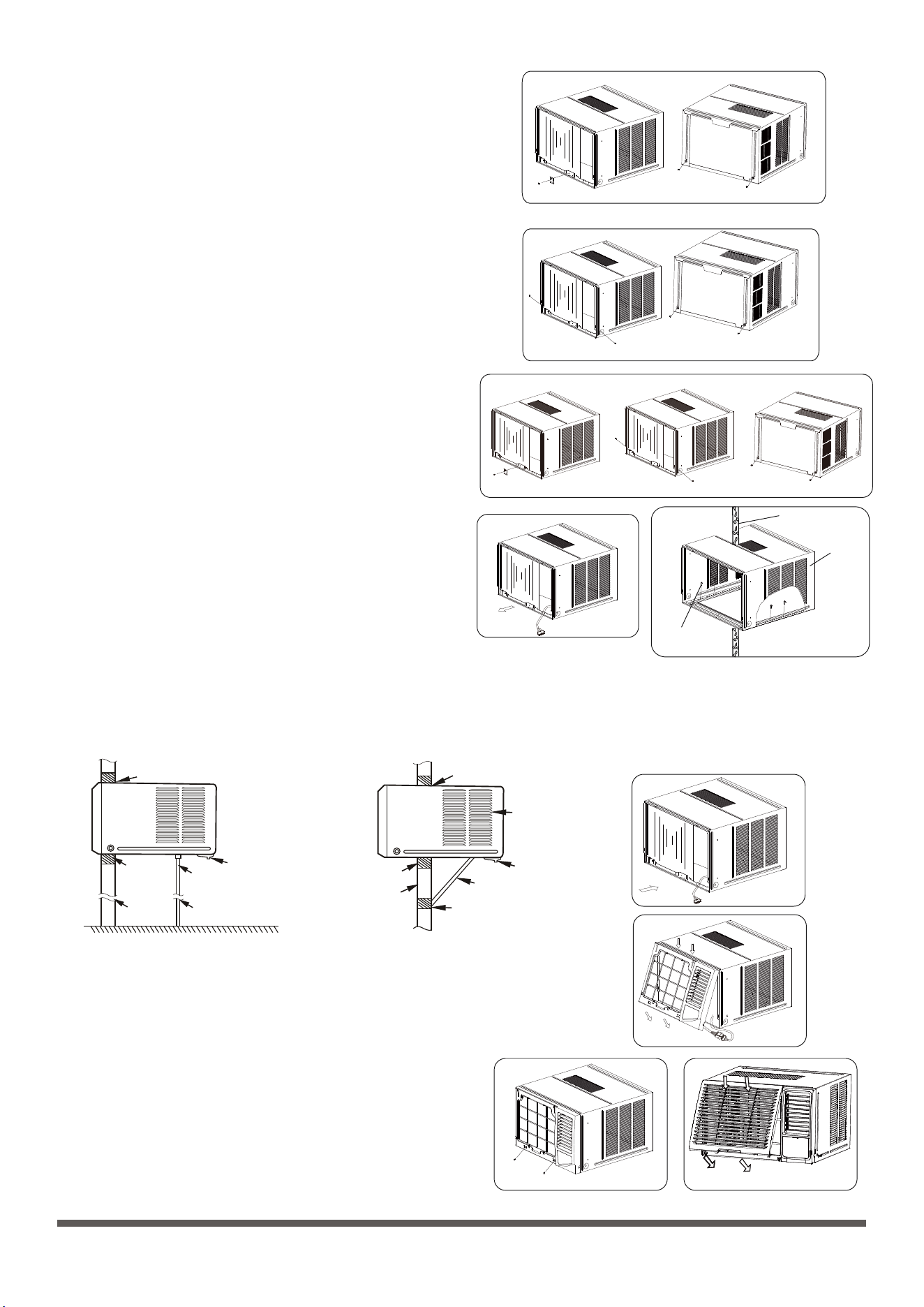
Step 3: Remove the frame
Step 2: Remove the front panel and air filter
1. Take out the air conditioner from it’s packaging.
2. Hold the slot under the front panel, then uplift it outwards, and
remove the front panel( See Fig. 1)
3. Grip the tab on the end of the filter, lift it up, then pull it towards
yourself, pull the filter out(see Fig.2)
Fig.3
Fig.5A-ModelA
1. Remove two screws at the bottom of the frame.( See Fig. 3)
2. Disconnect the coupler plugs and make sure not to interfere with
the temperature sensor cable. Hold the left bottom side of the
frame, lift it up to unlatch the lower side, remove it toward you
( See Fig. 4)
NOTE: For some units the front panel and frame do not install on the
machine placed at the back of the unit, step 2 and step 3 do not need.
13
Step 1: Select the best location
Prior to installation
INSTALLATION INSTRUCTIONS
CAUTION: Before installing, remove all packaging from
inside the carton, along with any inserts placed into the
side louvers.
CAUTION
All side louvers of the cabinet must remain exposed
to the outside of the structure.
Remove inserts placed
into the side louvers
1. To avoid vibration and noise, make sure the unit is installed securely and firmly.
2. Install the unit where the sunlight does not shine directly on the unit. If the unit
receives direct unlight, build an awning to shade the cabinet.
3. There should be no obstacle, such as a fence or wall, within 50cm from the
back of the cabinet because it will prevent heat radiation of the condenser.
Restriction of outside air will greatly reduce the cooling and heating efficiency
of the air conditioner.
4. Install the unit a little obliquely downward to outside not to leak the condensed
water into the room (about 5~7mm).
5. Install the unit with its bottom portion 75~150cm above the floor level.
6. The power cord must be connected to an independent circuit. The yellow/
green wire must be grounded.
300mm or more
800mm or
more
Awning
Fence
Outdoor
side
Indoor
side
Wall
75~150cm
500mm or more
Level
Unit
About 5~7mm
Option A
Air in
Air in
Air in
Air out
100mm Min.
500mm Min.
Option B
45 brick cut away
to clear louvers
Front
O
45 brick cut away
to clear louvers
O
Brick
wall
Brick
wall
Air in
100mm
Air out
100mm
Air in
Louver
Top View
Note on the product
•
•
The rated cooling performance is tested under non-drainage status.
Make sure that water will not leak from the surrounding area when rubber plug and joint were used. Please seal it in case
leakage is found.
Non-drainage
If you choose non-drainage when cooling, both the bottom and the back drain holes of the unit should be plugged with rubber
plugs. The condensed water will be sprayed to condenser, and will improve the cooling performance.
NOTE: When you choose non-drainage, the air conditioner will be perfect cooling efficiency, but big noise may be caused by spr-
aying the condensed water. Please do not choose it if you are sensitive to the noise.
Fig.4
Step 4: Remove the cabinet
NOTE: There are slight differences on removing the cabinet according
to the different models.
Model A:
1. Remove one screw securing the chassis fixing bracket, then take
down the chassis fixing bracket as shown in Fig.5A.
2. Grasp the handle on the chassis and carefully slide the air cond-
itioner out of the cabinet.(see Fig.6)

Step 6: Install the unit into the cabinet
Step 7: Install the frame
1. Slide the unit into the cabinet until it is firmly against the rear of the cabinet. Care is required to ensure the foam sealing strips on
the cabinet remain in position (See Fig.8).
2. Connect the air conditioner to the power and position excess cord length beneath the air conditioner base.
3. Engage the chassis fixing brackets into the bottom cabinet rail and secure to the base with the screw provided.
1. Hook the upper edge of the frame. Then connect the coupler
plugs and make sure not to interfere with the temperature sensor
cable(see Fig.9).
2. Press the both side and lower edge of the frame, and secure it
with the two screws at the bottom of the frame.( See Fig. 10)
Step 8: Install the air filter and front panel
1. Insert the air filter into the frame’s slot from upside to underside.
(See Fig. 2)
2. Hang the front panel on the frame’s buckle, then press the front
panel into the frame’s slot until you hear a click (see Fig.11).
3. Switch unit on. Check for operation of the unit and check for
vibration after installation.
4. Fit the drain pan to the cabinet and run a drain hose to a suitable
location if required.
Fig.10
Fig.11
Model C:
1. Remove four screws located on both sides and the back of the
cabinet as shown in Fig.5C.
2. Grasp the handle on the chassis and carefully slide the air cond-
itioner out of the cabinet.(see Fig.6)
Model D:
1. Remove one screw securing the chassis fixing bracket, then take
down the chassis fixing bracket.(see Fig.5D)
2. Remove four screws located on both sides and the back of the
cabinet as shown in Fig.5D.
3. Grasp the handle on the chassis and carefully slide the air cond-
itioner out of the cabinet.(see Fig.6)
Step 5: Install the cabinet
NOTE: Unit may be supported by a solid frame from below or by
a hanger from a solid overhead support(not suppied, purchase
separately, please contact the dealer).
1. When need to drain off water, install the drain plug on the ch-
assis board.
2. Prepare the hole in the wall so that the bottom of the cabinet
is well supported, the top has minimum clearance and the air
inlet louvers have clearance as shown in previous page(Fig.
Option A & B). Holes from the outside through to the cavity
should be sealed. The cabinet should slop down towards the
rear by about 5~7mm to allow water formed during operation
to drain.
3. Install the cabinet into the wall and secure. Ensure the foam
seals are not damaged. Flash, seal or fill gaps around the inside
and outside to provide satisfactory appearance and protection
against the weather, insects and rodents. (see Fig.7)
Flash or seal around
external wall frame
or architrave
Drain pan
Preferred method of installation into a
timber framed wall, partition or window
Sturdy timber
frame all
round unit
Timber framed
wall or partition
External support
frame at balance
point of air conditioner
Alternatively, brackets as
illustrated below may be used
Flash or seal around
external wall frame
or architrave
Drain pan
Alternative method of installation if
external support can not be provided
Sturdy timber
frame
Timber framed
wall or partition
Ensure louvers
are entirely
outside the wall
Steadying bracket
(one per side)
Solid timber support
Fig.5B-ModelB
Fig.5C-ModelC
Fig.6
Fig.7
WALL
CABINET
SCREWS
Fig.5D-ModelD
14
Fig.8
Fig.9
Model B:
1. Remove one screw securing the chassis fixing bracket, then take
down the chassis fixing bracket. Remove two screws located on
the back of the cabinet as shown in Fig.5B.
2. Grasp the handle on the chassis and carefully slide the air cond-
itioner out of the cabinet.(see Fig.6)
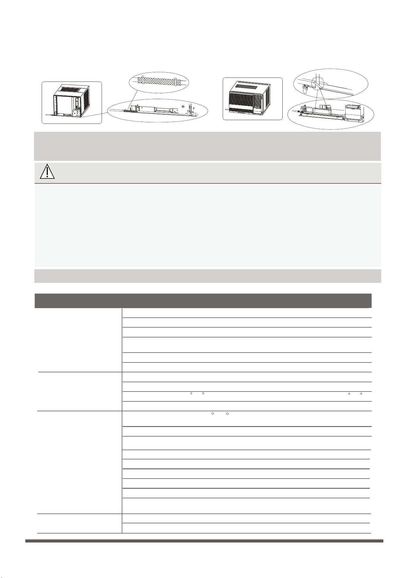
Common Issues
The following problems are not a malfunction and in most situations will not require repairs.
Troubleshooting
SAFETY PRECAUTIONS
If ANY of the following conditions occurs, turn off your unit immediately!
The power cord is damaged or abnormally warm
You smell a burning odor
The unit emits loud or abnormal sounds
A power fuse blows or the circuit breaker frequently trips
Water or other objects fall into or out of the unit
•
•
•
•
•
Issue Possible Causes
Unit does not turn
on when pressing
ON/OFF button
Wall plug disconnected. Push plug firmly into wall outlet.
Thermostat set too low. Adjust thermostat to higher number for cooling.
Turn selector to a higher COOL position.
Thermostat set too cold for night-time cooling. To defrost the coil, set selector to a FAN
position. Then, set thermostat to a warmer position.
Air filter may be dirty. Clean filter. Refer to Care and Maintenance section. To defrost, set selector to FAN.
Thermostat set too warm. Set thermostat to colder temperature.
Temperature sensing tube touching cold coil, located behind air filter. Straighten tube away from coil.
Room temperature below 18 C(64 F). Cooling may not occur until room temperature rise above 18 C(64 F).
Unit turned off and then on too quickly. Turn unit off and wait for 3 minutes before restarting.
House fuse blown or circuit breaker tripped. Replace fuse with time delay type or reset circuit breaker.
Selector Control in OFF position. Turn selector to the desired FAN or COOL setting.
Unit turned off by moving thermostat to a higher number and then immediately turning
back to a colder number. Wait approximately 3 minutes. Listen for compressor to start.
Air from unit does not
feel cold enough
Air conditioner cooling,
but room is too warm-
ice forming on cooling
coil behind decorative
front
Outdoor temperature below 18 C(64 F). To defrost the coil, set selector to FAN position.
Then, set thermostat to warmer position.
DO NOT ATTEMPT TO FIX THESE YOURSELF! CONTACT AN AUTHORIZED SERVICE PROVIDER
IMMEDIATELY!
Dirty air filter- air restricted. Clean air filter. Refer to Care and Maintenance section.
Unit recently turned on in hot room. Allow additional time to remove “Stored heat” from
walls, ceiling, floor and furniture.
Doors, windows, registers, etc. Open- cold air escapes. Close doors, windows, registers.
All directional louvers positioned improperly. Position louvers for better air distribution.
Thermostat set too warm. Turn thermostat clockwise to a colder setting.
Front of units is blocked by drapes, blinds, furniture, etc. - restricts air distribution. Clear blockage in front of unit.
Dirty air filter - air restricted. Clean air filter.
Outside temperature extremely hot. Set to high cool to bring air past cooling coils more frequently.
Air conditioner turns
on and off rapidly
15
NOTE: For the unit with power cord comes out from left side,
please perform the following steps:
1. Pull the power cord to the left side straightly(See Fig.a & b).
2. Wrap the PVC protecing sheath on the power cord with cable ties in the hole position (see Fig.c).
3. Tie up the power cord on the frame (see Fig.d & e) (Applicable for units with body dimension of 600mm*380mm*560mm only)
4. Install the frame and front panel according to the above Step 6 and Step 7.
Fig.a
Fig.b
Fig.c
Fig.d
Fig.e
Fig.f
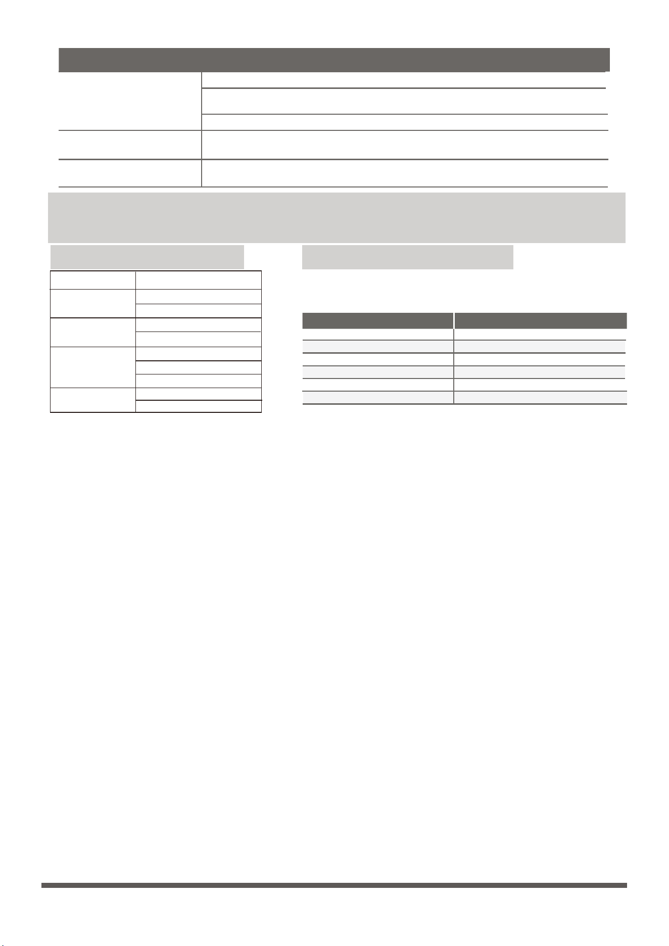
Issue Possible Causes
Air movement sound. This is normal. If too loud, turn selector to lower FAN setting.
Sound of fan hitting water-moisture removal system. This is normal when humidity is high.
Close doors, windows and registers.
Window vibration - poor installation. Refer to installation instructions or check with installer.
Improper installation. Tilt air conditioner slightly to the outside to allow water drainage.
Refer to installation instructions - check with installer.
Unit removing large quantity of moisture from humid room. This is normal during excessively humid days.
Noise when unit is
cooling
Water dripping INSIDE
when unit is cooling
Water dripping OUTSIDE
when unit is cooling
Unit dimensions: Choose the right cable size
MODEL(But/h)
Note: For the different customization requirements,
the deepth of the panel may be slightly different. So
the dimension of “D” is for reference only.
5000~6000
445x320x415
450x346x535
450x346x535
675x350x450.6
675x350x450.6
560x400x640
600x380x560
780x428x660
660x428x780
7000~9000
9000~12000
15000~24000
BODY DIMENSION(WxHxD)(mm)
SPECIFICATIONS
Minimum norminal cross-sectional area of conductors:
The size of the power supply cable, signal cable, fuse, and switch needed is determined by the
maximum current of the unit. The maximum current is indicated on the nameplate located on
the side panel of the unit. Refer to this nameplate to choose the right cable, fuse, or switch.
Rated Current of Appliance (A) Nominal Cross-Sectional Area (mm²)
> 3 and ≤ 6 0.75
1
1.5
2.5
4
6
> 32 and ≤ 40
> 25 and ≤ 32
> 16 and ≤ 25
> 10 and ≤ 16
> 6 and ≤ 10
16

CW002UI-F(E)RN8
The design and specifications are subject to change without prior notice for product
improvement. Consult with the sales agency or manufacturer for details. Any updates
to the manual will be uploaded to the service website, please check for the latest
version.

