Part Number 8014793 6/18
S Model Air Water Remote
Ice Machines
Technician’s Handbook

Safety Notices
As you work on Manitowoc equipment, be sure to pay
close attention to the safety notices in this handbook.
Disregarding the notices may lead to serious injury
and/or damage to the equipment.
Throughout this handbook, you will see the following
types of safety notices:
Procedural Notices
As you work on Manitowoc equipment, be sure to read
the procedural notices in this handbook. These notices
supply helpful information which may assist you as
you work.
Throughout this handbook, you will see the following
types of procedural notices:
!
Warning
Text in a Warning box alerts you to a potential
personal injury situation. Be sure to read the
Warning statement before proceeding, and work
carefully.
!
Caution
Text in a Caution box alerts you to a situation in
which you could damage the equipment. Be sure
to read the Caution statement before proceeding,
and work carefully.
Important
Text in an Important box provides you with
information that may help you perform a
procedure more efficiently. Disregarding this
information will not cause damage or injury, but it
may slow you down as you work.
NOTE: Text set off as a Note provides you with simple,
but useful, extra information about the procedure you
are performing.
Read These Before Proceeding:
!
Caution
Proper installation, care and maintenance are
essential for maximum performance and trouble-
free operation of your Manitowoc equipment. If
you encounter problems not covered by this
handbook, do not proceed, contact Manitowoc
Foodservice. We will be happy to provide
assistance.
Important
Routine adjustments and maintenance
procedures outlined in this handbook are not
covered by the warranty.
! Warning
PERSONAL INJURY POTENTIAL
Do not operate equipment that has been
misused, abused, neglected, damaged, or
altered/modified from that of original
manufactured specifications.
We reserve the right to make product
improvements at any time. Specifications and
design are subject to change without notice.

Part Number 8014793 6/18 5
Table of Contents
General Information
Model Numbers . . . . . . . . . . . . . . . . . . . . . 9
How to Read a Model Number . . . . . . 10
Ice Cube Sizes . . . . . . . . . . . . . . . . . . . . . 10
Model/Serial Number Location . . . . . . . . 11
Energy Efficient Ice Machine
Serial Breaks . . . . . . . . . . . . . . . . . . . . . . . 12
Installation
Location of Ice Machine . . . . . . . . . . . . . . 13
Ice Machine Clearance Requirements . . 14
Ice Machine Heat of Rejection . . . . . . . . . 15
Remote Condenser Line Set Installation 16
Calculating Remote Condenser
Installation Distances . . . . . . . . . . . . . 17
Lengthening or Reducing Line Set Lengths
. . . . . . . . . . . . . . . . . . . . . . . . . . . . . . . 19
Connecting A Line Set . . . . . . . . . . . . 20
Component Identification
S Model Single Evaporator Models . . . . . 21
S Model Quad Evaporator Models . . . . . 22
Maintenance
General . . . . . . . . . . . . . . . . . . . . . . . . . . . 23
Cleaning / Sanitizing Procedure . . . . . . . 24
Cleaning Procedure . . . . . . . . . . . . . . 24
Parts Removal for Cleaning/Sanitizing 26
Procedure to Clean Heavily Scaled
Ice Machines . . . . . . . . . . . . . . . . . . . . . . . 32
General . . . . . . . . . . . . . . . . . . . . . . . . 32
Cleaning Procedure . . . . . . . . . . . . . . 32
Parts Removal for Cleaning/Sanitizing 35
Removal from Service/Winterization . . . 47
Self-Contained Air-Cooled Ice Machines 47
Water-Cooled Ice Machines . . . . . . . . 48
Remote Ice Machines . . . . . . . . . . . . . 48

6 Part Number 8014793 6/18
Sequence of Operation
Self Contained Air or Water Cooled . . . . 49
Single & Quad Evaporator Models . . . 49
Safety Timers . . . . . . . . . . . . . . . . . . . . . . 54
Safety Limits . . . . . . . . . . . . . . . . . . . . . . 55
Remotes . . . . . . . . . . . . . . . . . . . . . . . 62
Troubleshooting
Safety Limits . . . . . . . . . . . . . . . . . . . . . . 69
Quad Evaporator Machines Only . . . . 70
Analyzing Why a Safety Limit Stopped the
Ice Machine . . . . . . . . . . . . . . . . . . . . 72
Safety Limit #1 . . . . . . . . . . . . . . . . . . 73
Safety Limit #2 . . . . . . . . . . . . . . . . . . 74
Safety Limit #3 . . . . . . . . . . . . . . . . . . 75
Control Board Testing . . . . . . . . . . . . . . . 76
Control Board Test Cycle . . . . . . . . . . 76
Troubleshooting By Symptom . . . . . . . . 77
Symptom #1 Ice Machine will not run . 78
Diagnosing an Ice Machine that Will Not Run
. . . . . . . . . . . . . . . . . . . . . . . . . . . . . . 80
Compressor Electrical Diagnostics . . . 81
Symptom #2 Low Production, Long Freeze
. . . . . . . . . . . . . . . . . . . . . . . . . . . . . . 83
Symptom #2 - Freeze Cycle Refrigeration
System Operational Analysis Tables . 85
Freeze Cycle Refrigeration System Opera-
tional Analysis Table Procedures . . . . 94
Harvest Problems . . . . . . . . . . . . . . . . . . 115
Symptom #3 Ice Will Not Harvest, Cubes
Are Not Melted . . . . . . . . . . . . . . . . . . 116
Symptom #3 - Traditional Remotes Only
. . . . . . . . . . . . . . . . . . . . . . . . . . . . . . 118
Symptom #4 Will Not Harvest, Melted
Cubes . . . . . . . . . . . . . . . . . . . . . . . . . 120

Part Number 8014793 6/18 7
Component Check Procedures
Electrical Components . . . . . . . . . . . . . . . 123
Main Fuse . . . . . . . . . . . . . . . . . . . . . . 123
ICE/OFF/CLEAN Toggle Switch . . . . . 124
Bin Switch . . . . . . . . . . . . . . . . . . . . . . 125
Cleaning the Ice Thickness or Water Level
Probe . . . . . . . . . . . . . . . . . . . . . . . . . . 128
Water Level Control Circuitry . . . . . . . 129
Ice Thickness Probe (Harvest Initiation)
. . . . . . . . . . . . . . . . . . . . . . . . . . . . . . . 134
Harvest Assist Air Pump . . . . . . . . . . . 139
Compressor Electrical Diagnostics . . . . 140
Diagnosing Start Components . . . . . . 142
Refrigeration Components . . . . . . . . . . . 146
High Pressure Cutout (HPCO) Control 146
Fan Cycle Control . . . . . . . . . . . . . . . . 148
Water Regulating Valve . . . . . . . . . . . 149
Harvest Pressure Regulating (HPR) System
Remotes Only . . . . . . . . . . . . . . . . . . . 150
Head Pressure Control Valve . . . . . . . 153
Low Pressure Cutout (LPCO) Control . 156
Harvest Pressure Solenoid Valve . . . . 157
Refrigerant Recovery/Evacuation . . . . . . 158
Normal Self-Contained Model Procedures
. . . . . . . . . . . . . . . . . . . . . . . . . . . . . . . 158
Normal Remote Model Procedures . . . 162
System Contamination Clean-Up . . . . . . 167
Determining Severity Of Contamination 167
Cleanup Procedure . . . . . . . . . . . . . . . 169
Replacing Pressure Controls Without Re-
moving Refrigerant Charge . . . . . . . . . 172
Specifications
Main Fuse . . . . . . . . . . . . . . . . . . . . . . 175
Fan Cycle Control . . . . . . . . . . . . . . . . 175
High Pressure Cutout (HPCO) Control 175
Filter-Driers . . . . . . . . . . . . . . . . . . . . . 176
Total System Refrigerant Charge . . . . 177

8 Part Number 8014793 6/18
Charts
Cycle Times/24-Hour Ice Production/
Refrigerant Pressure Charts . . . . . . . . . . 179
S300 Series . . . . . . . . . . . . . . . . . . . . 180
S320 Series . . . . . . . . . . . . . . . . . . . . 184
S420 Series . . . . . . . . . . . . . . . . . . . . 186
S450 Series . . . . . . . . . . . . . . . . . . . . 190
S500 Series . . . . . . . . . . . . . . . . . . . . 194
S600 Series . . . . . . . . . . . . . . . . . . . . 203
S850 Series . . . . . . . . . . . . . . . . . . . . 206
S1000 Series . . . . . . . . . . . . . . . . . . . 215
S1200 Series . . . . . . . . . . . . . . . . . . . 224
S1400 Series . . . . . . . . . . . . . . . . . . . 230
S1600 Series . . . . . . . . . . . . . . . . . . . 241
S1800 Series . . . . . . . . . . . . . . . . . . . 244
S3300 Series . . . . . . . . . . . . . . . . . . . 253
Diagrams
Wiring Diagrams . . . . . . . . . . . . . . . . . . . 257
Wiring Diagram Legend . . . . . . . . . . . 257
Wiring Diagrams Before Energy Efficient &
EnergyStar Machines . . . . . . . . . . . . . 258
Wiring Diagrams for Energy Efficient &
EnergyStar Machines . . . . . . . . . . . . . 269
Electronic Control Board . . . . . . . . . . . . 283
Single and Twin Evaporator Without Test
Button . . . . . . . . . . . . . . . . . . . . . . . . . 283
Single and Twin Evaporator With Test
Button . . . . . . . . . . . . . . . . . . . . . . . . . 284
Quad Evaporator Ice Machines . . . . . 285
Refrigeration Tubing Schematics . . . . . 286
Self-Contained Air- or
Water -Cooled Models . . . . . . . . . . . . 286
Remote Models . . . . . . . . . . . . . . . . . 288
Part Number 8014793 6/18 9
General Information
Model Numbers
This manual covers the following models:
NOTE: Model numbers ending in 3 indicate a 3
phase unit. Example: SY1004A3.
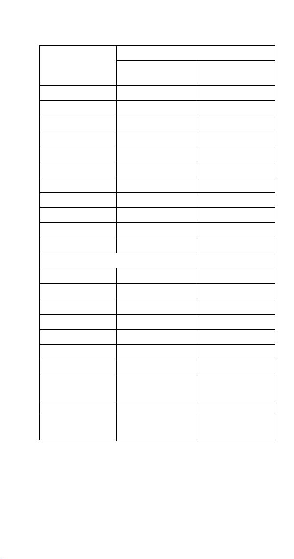
Self-Contained
Air-Cooled
Self-Contained
Water-Cooled
Remote
SD0302A
SY0304A
SD0303W
SY0305W
---
---
SD0322A
SY0324A
SD0323W
SY0325W
---
---
SR0420A
SD0422A
SY0424A
SR0421W
SD0423W
SY0425W
---
---
SD0452A
SY0454A
SD0453W
SY0455W
---
---
SR0500A
SD0502A
SY0504A
SR0501W
SD0503W
SY0505W
SD0592N
SY0594N
SD0602A
SY0604A
SD0603W
SY0605W
SD0692N
SY0694N
SR0850A
SD0852A
SY0854A
SR0851W
SD0853W
SY0855W
SR0890N
SD0892N
SY0894N
SR1000A
SD1002A
SY1004A
SR1001W
SD1003W
SY1005W
SR1090N
SD1092N
SY1094N
SD1202A
SY1204A
SD1203W
SY1205W
---
---
SD1402A
SY1404A
SD1403W
SY1405W
SD1492N
SY1494N
SR1600A
SD1602A
SY1604A
SR1601W
SD1603W
SY1605W
SR1690N
SD1692N
SY1694N
SR1800A
SD1802A
SY1804A
SR1801W
SD1803W
SY1805W
SR1890N
SD1892N
SY1894N
---
---
---
---
SD3303W
SD3303WHP
SY3305W
SY3305WHP
---
---
---
---
---
---
SDT3000W
SYT3000W
---
---
10 Part Number 8014793 6/18
HOW TO READ A MODEL NUMBER
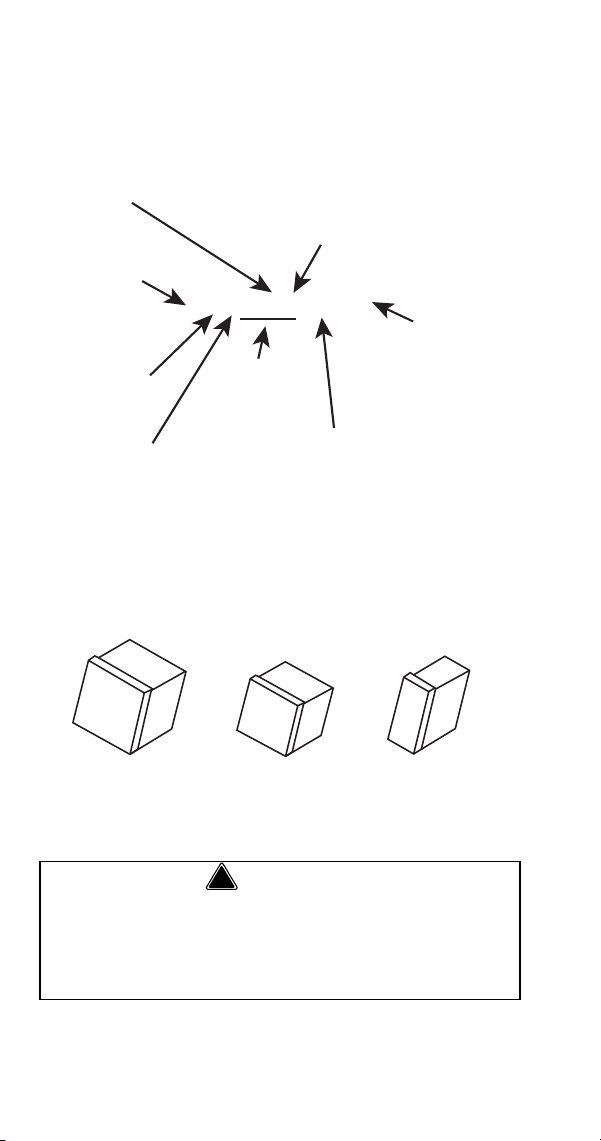
Ice Cube Sizes
Regular
1-1/8" x 1-1/8" x 7/8"
2.86 x 2.86 x 2.22 cm
Dice
7/8" x 7/8" x 7/8"
2.22 x 2.22 x2.22 cm
Half Dice
3/8" x 1-1/8" x 7/8"
0.95 x 2.86 x 2.22 cm
! Warning
Personal Injury Potential
Do not operate equipment that has been misused,
abused, neglected, damaged, or altered/modified
from that of original manufactured specifications.
S Y T 1094 N SI
ICE MACHINE
MODEL
ICE CUBE SIZE
R REGULAR
D DICE
Y HALF DICE
# CUBE SIZE
0 REGULAR
1 REGULAR
2 DICE
3 DICE
4 HALF-DICE
5 HALF-DICE
CONDENSER TYPE
AIR-COOLED
WATER-COOLED
AIR-COOLED
WATER-COOLED
AIR-COOLED
WATER-COOLED
A SELF-CONTAINED AIR-COOLED
W SELF-CONTAINED WATER-COOLED
N REMOTE AIR-COOLED
9 REMOTE
AIR-COOLED
CONDENSER TYPE
ICE MACHINE
SERIES
ADDITIONAL SPECS
3 PHASE
M MARINE UNIT
HP HIGH PRESSURE
WATER VALVE
SI AUCS-SI INCLUDED
REFRIGERANT
TYPE
T R410A
ST3000W Only

Part Number 8014793 6/18 11
Model/Serial Number Location
These numbers are required when requesting
information from your local Manitowoc Distributor,
service representative, or Manitowoc Ice, Inc. The
model and serial number are listed on the OWNER
WARRANTY REGISTRATION CARD. They are also
listed on the MODEL/SERIAL NUMBER DECAL
affixed to the ice machine.
! Warning
All Manitowoc ice machines require the ice
storage system (bin, dispenser, etc.) to
incorporate an ice deflector.
48” wide S Model ice machines require adding
Manitowoc Ice Deflector Kit K00349 when
installing with non-Manitowoc ice storage
systems.
30” wide S Model ice machines require adding
Manitowoc Ice Deflector Kit K00347 when
installing with non-Manitowoc ice storage
systems.
Prior to using a non-Manitowoc ice storage
system with other Manitowoc ice machines,
contact the manufacturer to assure their ice
deflector is compatible with Manitowoc ice
machines.
12 Part Number 8014793 6/18
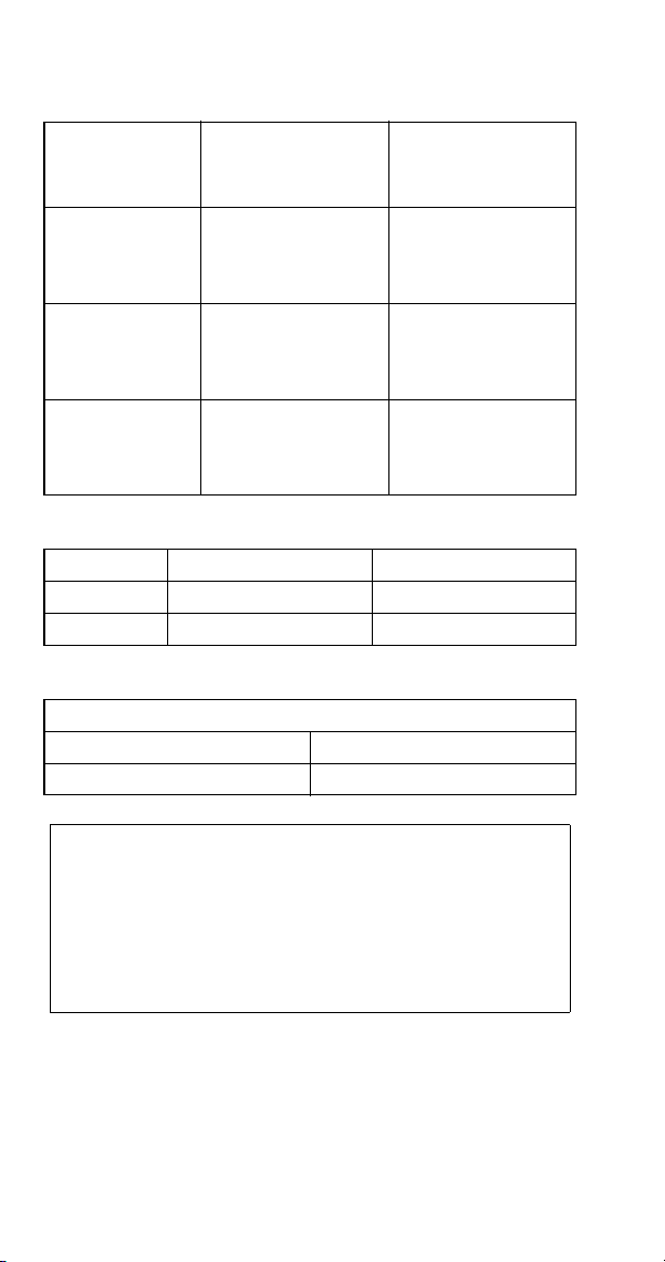
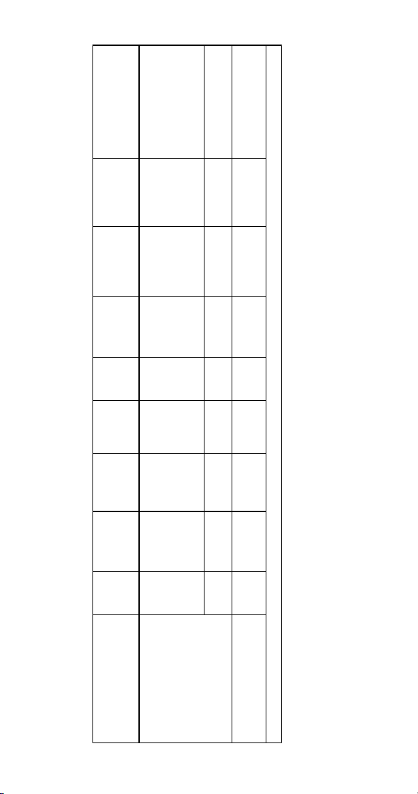
Energy Efficient Ice Machine
Serial Breaks
Some specifications have changed with our release of
more Energy Efficient machines. The following
machines have a serial break to indicate when they
became more Energy Efficient.
Series Ice
Machine
Serial Break/Manufacture Date for
Energy Efficient Machines
S300 110704351
S420 110667970
S450 110670157
S500 110684316
S850 110683282
S1000 110697023
S1200 110707329
S1400W
Manufacture Date After 0711
(November 2007)
S1400W
Manufacture Date Between
0711 & 0905
(November 2007 & May 2009)
S1400A
S1400W
S1400N
Manufacture Date After 0905
(May 2009)
S1800A
S1800W
S1800N
Manufacture Date After 0910
(October 2009)
SYT3000W
SDT3000W
Model number was changed to
indicate refrigerant type change and
energy efficiency increase.

Part Number 8014793 6/18 13
Installation
Location of Ice Machine
The location selected for the ice machine head section
must meet the following criteria. If any of these criteria
are not met, select another location.
• The location must be free of airborne and other
contaminants.
• Self contained air and water cooled - The air
temperature must be at least 35°F (1.6°C), but
must not exceed 110°F (43.4°C).
• Remote air cooled - The air temperature must be
at least -20°F (-29°C), but must not exceed 120°F
(49°C)
• Ice Making Water Inlet - Water Pressure must be
at least 20 psi (1.38 bar), but must not exceed 80
psi (5.52 bar).
• Condenser Water Inlet - Water Pressure must be
at least 20 psi (1.38 bar), but must not exceed
150 psi (10.34 bar). S3300W-HP units allow water
pressure up to 350 psig (24.13 bar)
.
• The location must not be near heat-generating
equipment or in direct sunlight and protected from
weather.
• The location must not obstruct air flow through or
around the ice machine. Refer to chart below for
clearance requirements.
• The ice machine must be protected if it will be
subjected to temperatures below 32°F (0°C).
Failure caused by exposure to freezing
temperatures is not covered by the warranty. See
“Removal from Service/Winterization”
!
Warning
PERSONAL INJURY POTENTIAL
Remove all ice machine panels before lifting and
installing.
14 Part Number 8014793 6/18
Ice Machine Clearance Requirements
S300
Self-Contained
Air-Cooled
Self-Contained
Water-Cooled
Top/Sides 16" (40.6 cm) 8" (20.3 cm)
Back 5" (12.7 cm) 5" (12.7 cm)
S320/S450/S500/
S600/S850/S1000
Self-Contained
Air-Cooled
Water-Cooled and
Remote*
Top/Sides 8" (20.3 cm) 8" (20.3 cm)
Back 5" (12.7 cm) 5" (12.7 cm)
S420
Self-Contained
Air-Cooled
Water-Cooled and
Remote*
Top/Sides 12" (30.5 cm) 8" (20.3 cm)
Back 5" (12.7 cm) 5" (12.7 cm)
S1200
Self-Contained
Air-Cooled
Water-Cooled and
Remote*
Top 8" (20.3 cm) 8" (20.3 cm)
Sides 12" (30.5 cm) 8" (20.3 cm)
Back 5" (12.7 cm) 5" (12.7 cm)
S1400/S1600/
S1800
Self-Contained
Air-Cooled
Water-Cooled
and Remote*
Top/Sides 24" (61.0 cm) 8" (20.3 cm)
Back 12" (30.5 cm) 5" (12.7 cm)
*
* There is no minimum clearance required for water-cooled or
remote ice machines. This value is recommended for efficient
operation and servicing only.
ST3000/S3300
**
** ST3000/S3300 - 24” on all sides is recommended to allow access
without moving the bin/ice machine.
Water-Cooled
Top/Sides 8" (20.3 cm)
Back 24" (61.0 cm)
Part Number 8014793 6/18 15
Ice Machine Heat of Rejection
Series Ice
Machine
Heat of Rejection
Air
Conditioning*
Peak
S300 3,800 6,000
S320 3,800 6,000
S420/S450 7,000 9,600
S500 7,000 9,600
S600 9,000 13,900
S850 12,000 18,000
S1000 16,000 22,000
S1200 19,000 28,000
S1400 19,000 28,000
S1600 21,000 31,000
S1800 24,000 36,000
Energy Efficient Machines
S300 5,000 6,000
S420/S450 5,900 6,900
S500 6,100 6,900
S850 13,000 16,000
S1000 17,700 21,000
S1200 20,700 24,500
S1400W 25,000 28,000
S1400A/
S1400N
23,500 27,000
S1800 31,000 36,000
ST3000
S3300
45,000 51,000
*BTU/Hour
Because the heat of rejection varies during the ice making
cycle, the figure shown is an average.
16 Part Number 8014793 6/18
REMOTE CONDENSER LINE SET INSTALLATION
Ice Machine
Remote Single
Circuit
Condenser
Line Set*
S500 JC0495
RT-20-R404A
RT-35-R404A
RT-50-R404A
S600
S800
S1000
JC0895
RT-20-R404A
RT-35-R404A
RT-50-R404A
S1400
S1600
S1800
JC1395
RL-20-R404A
RL-35-R404A
RL-50-R404A
*Line Set Discharge Line Liquid Line
RT 1/2" (1.27 cm) 5/16" (.79 cm)
RL 1/2" (1.27 cm) 3/8" (.95 cm)
Air Temperature Around the Condenser
Minimum Maximum
-20°F (-29°C) 120°F (49°C)
Important
Manitowoc remote systems are only approved
and warranted as a complete new package.
Warranty on the refrigeration system will be
void if a new ice machine head section is
connected to pre-existing (used) tubing or
remote condensers or vice versa.
Part Number 8014793 6/18 17
CALCULATING REMOTE CONDENSER
INSTALLATION DISTANCES
NOTE: Manitowoc warrants only complete new and
unused remote packages. Warranty on the
refrigeration system will be void if a new ice machine
head section is connected to existing (used) tubing or
condensers.
Line Set Length
The maximum length is 100' (30.5 m).
The ice machine compressor must have the proper oil
return. The receiver is designed to hold a charge
sufficient to operate the ice machine in ambient
temperatures between -20°F (-28.9°C) and 120°F
(49°C), with line set lengths of up to 100' (30.5 m).
Line Set Rise/Drop
The maximum rise is 35' (10.7 m).
The maximum drop is 15' (4.5 m).
!
Caution
If a line set has a rise followed by a drop, another
rise cannot be made. Likewise, if a line set has a
drop followed by a rise, another drop cannot be
made.

18 Part Number 8014793 6/18
Calculated Line Set Distance
The maximum calculated distance is 150' (45.7 m).
Line set rises, drops, horizontal runs (or combinations
of these) in excess of the stated maximums will
exceed compressor start-up and design limits. This will
cause poor oil return to the compressor.
Make the following calculations to make sure the line
set layout is within specifications.
1. Insert the measured rise into the formula below.
Multiply by 1.7 to get the calculated rise.
(Example: A condenser located 10 feet above the
ice machine has a calculated rise of 17 feet.)
2. Insert the measured drop into the formula below.
Multiply by 6.6 to get the calculated drop.
(Example. A condenser located 10 feet below the
ice machine has a calculated drop of 66 feet.)
3. Insert the measured horizontal distance into the
formula below. No calculation is necessary.
4. Add together the calculated rise, calculated
drop, and horizontal distance to get the total
calculated distance. If this total exceeds 150'
(45.7 m), move the condenser to a new location
and perform the calculations again.

Part Number 8014793 6/18 19
Maximum Line Set Distance Formula
Step 1
Measured Rise ____ X 1.7 = ______Calculated Rise
(35 ft. Max)
Step 2
Measured Drop ____ X 6.6 = ______Calculated Drop
(15 ft. Max.)
Step 3
Measured Horizontal Distance = _________Horizontal
(100 ft. Max.) Distance
Step 4
Total Calculated Distance = ________Total Calculated
(150 ft. Max.) Distance
LENGTHENING OR REDUCING LINE SET
LENGTHS
In most cases, by routing the line set properly,
shortening will not be necessary. When shortening or
lengthening is required, do so before connecting the
line set to the ice machine or the remote condenser.
This prevents the loss of refrigerant in the ice machine
or condenser.
The quick connect fittings on the line sets are
equipped with Schraeder valves. Use these valves to
recover any vapor charge from the line set. When
lengthening or shortening lines follow good
refrigeration practices, purge with nitrogen and
insulate all tubing. Do not change the tube sizes.
Evacuate the lines and place about 5 oz (143g) of
vapor refrigerant charge in each line.

20 Part Number 8014793 6/18
CONNECTING A LINE SET
1. Remove the dust caps from the line set,
condenser and ice machine.
2. Apply refrigeration oil to the threads on the quick
disconnect couplers before connecting them to
the condenser.
3. Carefully thread the female fitting to the
condenser or ice machine by hand.
4. Tighten the couplings with a wrench until they
bottom out.
5. Turn an additional 1/4 turn to ensure proper
brass-to-brass seating. Torque to the following
specifications:
6. Check all fittings and valve caps for leaks.
7. Make sure Schraeder cores are seated and
Schraeder caps are on and tight.
Liquid Line Discharge Line
10-12 ft lb.
(13.5-16.2 N•m)
35-45 ft lb.
(47.5-61.0 N•m)
Part Number 8014793 6/18 21
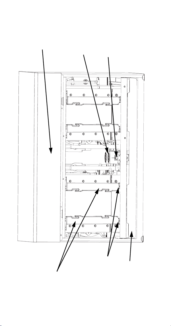
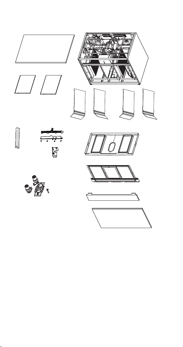
Component Identification
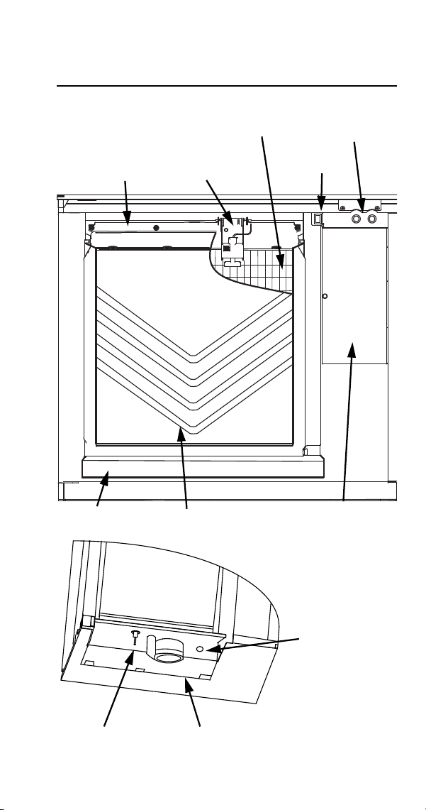
S Model Single Evaporator Models
WATER CURTAIN
CONTROL BOX
WATER
DISTRIBUTION
TUBE
TOGGLE
SWITCH
WATER
TROUGH
REFRIGERATION
ACCESS VALVES
ICE
THICKNESS
CONTROL
EVAPORATOR
WATER LEVEL
PROBE
WATER PUMP
WATER INLET
LOCATION, THE
WATER INLET VALVE
IS LOCATED IN THE
REFRIGERATION
COMPARTMENT
22 Part Number 8014793 6/18
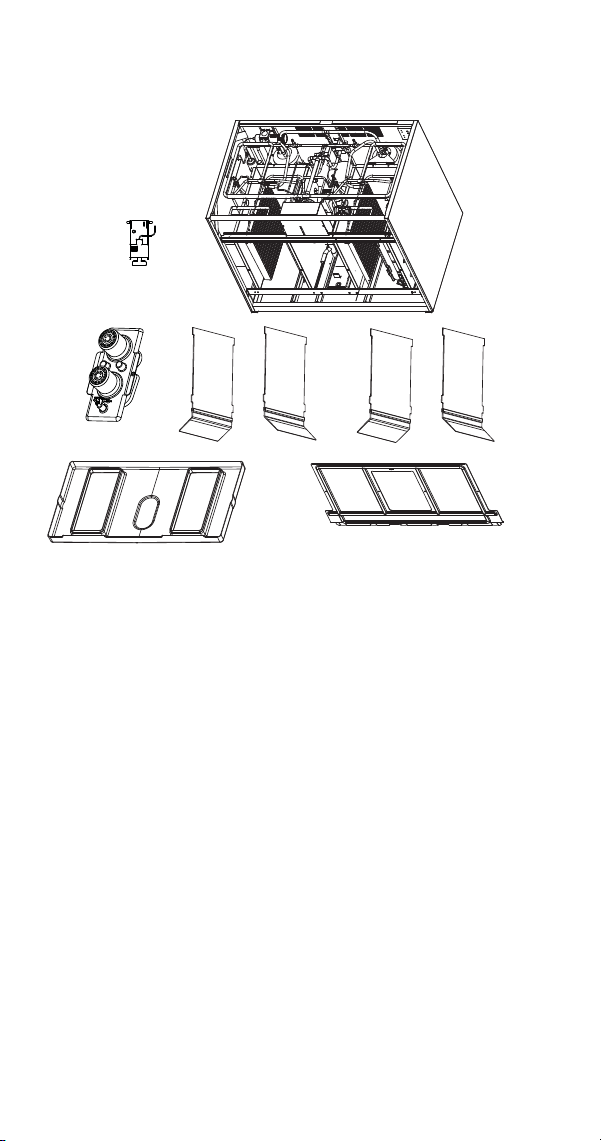
S Model Quad Evaporator Models
WATER
PUMPS
WATER LEVEL
PROBE
EVAPORATORS
WATER
TROUGH
CONTROL
BOX
ICE DAMPERS

Part Number 8014793 6/18 23
Maintenance
General
Clean and sanitize the ice machine every six months
for efficient operation. If the ice machine requires more
frequent cleaning and sanitizing, consult a water care
professional to test the water quality and recommend
appropriate water treatment. An extremely dirty ice
machine must be taken apart for cleaning and
sanitizing.
Manitowoc Ice Machine Cleaner and Sanitizer are the
only products approved for use in Manitowoc ice
machines.
This Manitowoc Ice Machine has two separate
cleaning procedures.
Cleaning/Sanitizing Procedure
This procedure must be performed a minimum of once
every six months.
• The ice machine and bin must be disassembled
cleaned and sanitized
• All ice produced during the cleaning and sanitizing
procedures must be discarded
• Removes mineral deposits from areas or surfaces
that are in direct contact with water
Heavily Scaled Cleaning Procedure
Perform this procedure if you have some or all of these
symptoms.
• Ice machine stops on Safety Shutdown
• Your water has a high concentration of minerals
• The ice machine has not been on a regular
maintenance schedule.
24 Part Number 8014793 6/18
Cleaning / Sanitizing Procedure
CLEANING PROCEDURE
Ice machine cleaner is used to remove lime scale and
mineral deposits. Ice machine sanitizer disinfects and
removes algae and slime.
Step 1 Remove front door and top cover. This will
allow easiest access for adding cleaning and
sanitizing solutions.
Step 2 Set the toggle switch to the OFF position after
ice falls from the evaporator at the end of a Harvest
cycle. Or, set the switch to the OFF position and allow
the ice to melt off the evaporator.
!
Caution
Use only Manitowoc approved Ice Machine
Cleaner and Sanitizer for this application
(Manitowoc Cleaner part number 9405463 and
Manitowoc Sanitizer part number 9405653). It is a
violation of Federal law to use these solutions in a
manner inconsistent with their labeling. Read and
understand all labels printed on bottles before
use.
!
Caution
Do not mix Cleaner and Sanitizer solutions
together. It is a violation of Federal law to use
these solutions in a manner inconsistent with their
labeling.
!
Warning
Wear rubber gloves and safety goggles (and/or
face shield) when handling ice machine Cleaner
or Sanitizer.
!
Caution
Never use anything to force ice from the
evaporator. Damage may result.
Part Number 8014793 6/18 25
Step 3 Remove all ice from the bin.
Step 4 Place the toggle switch in the CLEAN
position. The water will flow through the water dump
valve and down the drain. Wait until the water trough
refills and water flows over the evaporator, then add
the proper amount of ice machine cleaner.
Step 5 Wait until the clean cycle is complete
(approximately *35 minutes). then place the toggle
switch in the OFF position and disconnect power to
the ice machine (and dispenser when used).
NOTE: *ST3000/S3300 Only - 80 minutes..
Step 6 Remove parts for cleaning.
Please refer to the proper parts removal for your
ice machine.
Single Evaporator Ice Machines - page 26.
Quad Evaporator Ice Machines - page 27.
Model Amount of Cleaner
S300/S320/S420 3 ounces (90 ml)
S450/S500/S600/S850/
S1000/S1200
5 ounces (150 ml)
S1400/S1600/S1800 9 ounces (265 ml)
ST3000/S3300 16 ounces (475 ml)
!
Warning
Disconnect the electric power to the ice machine
at the electric service switch box.
26 Part Number 8014793 6/18
PARTS REMOVAL FOR CLEANING/SANITIZING
Single Evaporator Ice Machines
A. Remove the water curtain
• Gently flex the curtain in the center and remove it
from the right side.
• Slide the left pin out.
B. Remove the ice thickness probe
• Compress the hinge pin on the top of the ice
thickness probe.
• Pivot the ice thickness probe to disengage one pin
then the other. The ice thickness probe can be
cleaned at this point without complete removal. If
complete removal is desired, disconnect the ice
thickness control wiring from the control board.
C. Remove the water trough
• Depress tabs on right and left side of the water
trough.
• Allow front of water trough to drop as you pull
forward to disengage the rear pins.
NOTE: Proceed to page 29, Step 7.
A.
B.
C.

Part Number 8014793 6/18 27
Quad Evaporator Ice Machines
A.Remove the water trough shield.
• Grasp the water trough shield in the center and the
left end.
• Flex the water trough shield in the center and pull
the left end forward until clear of the side wall.
Repeat for the right end.
• Pull water trough shield forward to remove.
B. Remove Splash Shields.
• Grasp the top center of splash shields.
• Lift up and then out.
C. Remove ice thickness probe.
• Compress the hinge pin on the top of the ice
thickness probe.
• Pivot the ice thickness probe to disengage one pin
then the other. The ice thickness probe can be
cleaned at this point without complete removal. If
complete removal is desired, disconnect the ice
thickness control wiring from the control board.
D. Remove the water pump assembly
• Disconnect the vinyl distribution tube from both
water pumps.
• Disconnect the water pump and water level probe
electrical connections.
• Remove two thumbscrews and lift the water pump
assembly out of the ice machine.
E. Remove the water trough.
• Depress the two tabs on the top of the water
trough.
• Turn left and right ice dampers down to clear water
trough.
• Pull forward on the water trough to remove.
NOTE: Proceed to page 29, Step 7.
Continued on next page …
28 Part Number 8014793 6/18
A
B
C
D
E

Part Number 8014793 6/18 29
Step 7 Mix a solution of cleaner and warm water.
Depending upon the amount of mineral buildup, a
larger quantity of solution may be required. Use the
ratio in the table below to mix enough solution to
thoroughly clean all parts.
Step 8 Use 1/2 of the cleaner/water mixture to clean
all components. The cleaner solution will foam when it
contacts lime scale and mineral deposits; once the
foaming stops use a soft-bristle nylon brush, sponge
or cloth (NOT a wire brush) to carefully clean the parts.
Soak parts for 5 minutes (15 - 20 minutes for heavily
scaled parts). Rinse all components with clean water.
Step 9 While components are soaking, use 1/2 of the
cleaner/water solution to clean all foodzone surfaces
of the ice machine and bin (or dispenser). Use a nylon
brush or cloth to thoroughly clean the following ice
machine areas:
• Side walls
• Base (area above water trough)
• Evaporator plastic parts - including top, bottom,
and sides
• Bin or dispenser
Rinse all areas thoroughly with clean water.
Continued on next page …
Solution Type Water Mixed With
Cleaner 1 gal. (4 l)
16 oz (500 ml)
cleaner

30 Part Number 8014793 6/18
Step 10 Mix a solution of sanitizer and warm water.
Step 11 Use 1/2 of the sanitizer/water solution to
sanitize all removed components. Use a spray bottle
to liberally apply the solution to all surfaces of the
removed parts or soak the removed parts in the
sanitizer/water solution. Do not rinse parts after
sanitizing.
Step 12 Use 1/2 of the sanitizer/water solution to
sanitize all foodzone surfaces of the ice machine and
bin (or dispenser). Use a spray bottle to liberally apply
the solution. When sanitizing, pay particular attention
to the following areas:
• Side walls
• Base (area above water trough)
• Evaporator plastic parts - including top, bottom and
sides
• Bin or dispenser
Do not rinse the sanitized areas.
Step 13 Replace all removed components.
Step 14 Wait 30 minutes.
Solution Type Water Mixed With
Sanitizer 6 gal. (23 l)
4 oz (120 ml)
sanitizer

Part Number 8014793 6/18 31
Step 15 Reapply power to the ice machine and place
the toggle switch in the CLEAN position.
Step 16 Wait until the water trough refills and water
flows over the evaporator (approximately 3 minutes).
Add the proper amount of Manitowoc Ice Machine
Sanitizer to the water trough by pouring between the
water curtain/splash shields and evaporator..
Step 17 Move the toggle switch to the ICE position
and replace the front panel. The ice machine will
automatically start ice making after the sanitize cycle
is complete (approximately 35 minutes)
ST3000/S3300 approximately 80 minutes.
Model Amount of Sanitizer
S300/S320/S420 3 ounces (90 ml)
S450/S500/S600/S850/
S1000/S1200
3 ounces (90 ml)
S1400/S1600/S1800 6 ounces (180 ml)
ST3000/S3300 25 ounces (740 ml)
32 Part Number 8014793 6/18
Procedure to Clean Heavily Scaled
Ice Machines
Ice machines that are heavily scaled or have not been
cleaned on a regular basis will need to run this
procedure.
GENERAL
Clean and sanitize the ice machine every six months
for efficient operation. If the ice machine requires more
frequent cleaning and sanitizing, consult a qualified
service company to test the water quality and
recommend appropriate water treatment. The ice
machine must be taken apart for cleaning and
sanitizing.
CLEANING PROCEDURE
!
Caution
Use only Manitowoc approved Ice Machine
Cleaner and Sanitizer for this application
(Manitowoc Cleaner part number 9405463 and
Manitowoc Sanitizer part number 9405653). It is
a violation of Federal law to use these solutions in
a manner inconsistent with their labeling. Read
and understand all labels printed on bottles
before use.
!
Caution
Do not mix Cleaner and Sanitizer solutions
together. It is a violation of Federal law to use
these solutions in a manner inconsistent with
their labeling.
!
Warning
Wear rubber gloves and safety goggles (and/or
face shield) when handling ice machine Cleaner
or Sanitizer.
Part Number 8014793 6/18 33
Ice machine cleaner is used to remove lime scale and
mineral deposits. Ice machine sanitizer disinfects and
removes algae and slime.
Step 1 Set the toggle switch to the OFF position after
ice falls from the evaporator at the end of a Harvest
cycle. Or, set the switch to the OFF position and allow
the ice to melt off the evaporator.
Step 2 Remove top cover. This will allow easiest
access for adding cleaning and sanitizing solutions.
Step 3 Remove all ice from the bin.
Step 4 Place the toggle switch in the CLEAN
position. The water will flow through the water dump
valve and down the drain. Wait until the water trough
refills and water flows over the evaporator, then add
the proper amount of ice machine cleaner.
Continued on next page …
!
Caution
Never use anything to force ice from the
evaporator. Damage may result.
Model Amount of Cleaner
S300/S320/S420 3 ounces (90 ml)
S450/S500/S600/S850/
S1000/S1200
5 ounces (150 ml)
S1400/S1600/S1800 9 ounces (265 ml)
ST3000/S3300 16 ounces (475 ml)

34 Part Number 8014793 6/18
Step 5 Wait until the clean cycle is complete
(approximately *35 minutes). then place the toggle
switch in the OFF position and disconnect power to
the ice machine (and dispenser when used)
NOTE: *ST3000/S3300 approximately 80 minutes..
Step 6 Remove parts for cleaning.
Please refer to the proper parts removal for your ice
machine.
Single Evaporator Ice Machines - page 35.
Quad Evaporator Ice Machines - page 38.
!
Warning
Disconnect the electric power to the ice machine
at the electric service switch box.

Part Number 8014793 6/18 35
PARTS REMOVAL FOR CLEANING/SANITIZING
Single Evaporator Ice Machines
A. Remove the water curtain
• Gently flex the curtain in the center and remove it
from the right side.
• Slide the left pin out.
B. Remove the ice thickness probe
• Compress the hinge pin on the top of the ice
thickness probe.
• Pivot the ice thickness probe to disengage one pin
then the other. The ice thickness probe can be
cleaned at this point without complete removal. If
complete removal is desired, disconnect the ice
thickness control wiring from the control board.
C. Remove the water distribution tube
NOTE: Distribution tube thumbscrews are retained to
prevent loss. Loosen thumbscrews but do not pull
thumbscrews out of distribution tube.
• Loosen the two outer screws (do not remove
screws completely they are retained to prevent
loss) and pull forward on the distribution tube to
release from slip joint.
• Disassemble distribution tube by loosening the two
(2) middle thumbscrews and dividing the
distribution tube into two pieces.
D. Remove the water trough
• Depress tabs on right and left side of the water
trough.
• Allow front of water trough to drop as you pull
forward to disengage the rear pins.

36 Part Number 8014793 6/18
E. Remove the water level probe
• Pull the water level probe straight down to
disengage.
• Lower the water level probe until the wiring
connector is visible.
• Disconnect the wire lead from the water level
probe.
• Remove the water level probe from the ice
machine.
F. Remove the water pump.
• Grasp pump and pull straight down on pump
assembly until water pump disengages and
electrical connector is visible.
• Disconnect the electrical connector.
• Remove the water pump assembly from ice
machine.
• Do not soak the water pump motor in cleaner or
sanitizer solution.
G. Remove the evaporator tray or water diverter
from the bottom of the evaporator.
• Loosen thumbscrew on left side of tray.
• Allow left side of tray to drop as you pull the tray to
the left side. Continue until the outlet tube
disengages from the right side.
NOTE: Proceed to page 41, Step 7.
Part Number 8014793 6/18 37
A.
B.
C.
D.
E.
F.
G.

38 Part Number 8014793 6/18
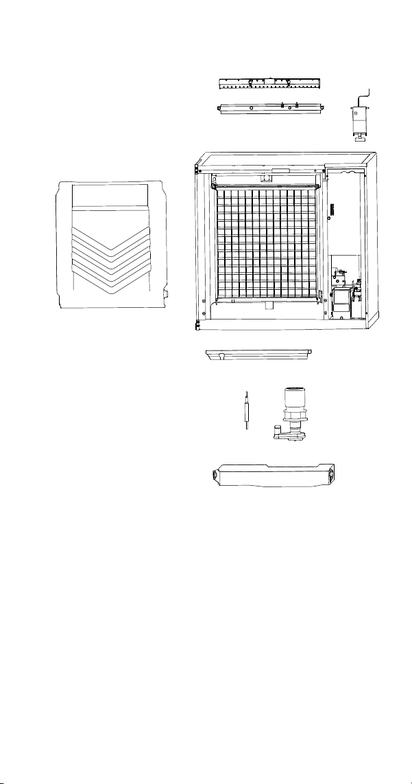
Quad Evaporator Ice Machines
A. Remove panels
• Remove both front panels
• Remove top panel
B. Remove front evaporator shield.
• Remove four quarter turn connectors
• Remove splash shield
C. Remove left and right evaporator top covers.
• Remove two thumbscrews from the front of each
evaporator top cover.
• Lift front of cover, pull forward to remove.
D. Remove Splash Shields.
• Grasp the top center of splash shields.
• Lift up and then out.
NOTE: Each evaporator has a splash shield that must
be removed - total of four splash shields.
E. Remove ice thickness probe.
• Compress the hinge pin on the top of the ice
thickness probe.
• Pivot the ice thickness probe to disengage one pin
then the other. The ice thickness probe can be
cleaned at this point without complete removal. If
complete removal is desired, disconnect the ice
thickness control wiring from the control board.

Part Number 8014793 6/18 39
F. Remove distribution tubes.
• Distribution tube thumbscrews are retained to
prevent loss. Loosen thumbscrews but do not pull
thumbscrews out of distribution tube.
• Loosen the two outer screws and pull forward on
the distribution tube to release from slip joint.
• Disassemble distribution tube by loosening the two
(2) middle thumbscrews and dividing the
distribution tube into two pieces.
NOTE: Each evaporator has a distribution tube that
must be removed - total of four distribution tubes.
G. Remove ice dampers.
• Grasp ice damper and apply pressure toward the
back mounting bracket.
• Apply pressure to the front mounting bracket with
thumb.
• Pull ice damper downward when the front ice
damper pin disengages.
NOTE: Each evaporator has an ice damper that must
be removed - total of four ice dampers.
H. Remove the water pump assembly.
• Disconnect the vinyl distribution tube from both
water pumps.
• Disconnect the water pump and water level probe
electrical connections.
• After the wires are disconnected remove the two
thumbscrews and lift the water pump assembly out
of the ice machine.
• Remove the thumbscrews securing the water
pumps (2 each pump) and remove water pumps.
Do not immerse the water pump motor in cleaner
or sanitizer solutions.
• Remove the water level probe from the assembly
housing.
I. Remove the water trough.
• Pull forward on the water trough to remove.
NOTE: Proceed to page 41, Step 7.
40 Part Number 8014793 6/18
A
A
B
C
D
E
F
G
H
I

Part Number 8014793 6/18 41
Step 7 Mix a solution of cleaner and warm water.
Depending upon the amount of mineral buildup, a
larger quantity of solution may be required. Use the
ratio in the table below to mix enough solution to
thoroughly clean all parts.
Step 8 Use 1/2 of the cleaner/water mixture to clean
all components. The cleaner solution will foam when it
contacts lime scale and mineral deposits; once the
foaming stops use a soft-bristle nylon brush, sponge
or cloth (NOT a wire brush) to carefully clean the parts.
Soak parts for 5 minutes (15 - 20 minutes for heavily
scaled parts). Rinse all components with clean water.
Step 9 While components are soaking, use 1/2 of the
cleaner/water solution to clean all foodzone surfaces
of the ice machine and bin (or dispenser). Use a nylon
brush or cloth to thoroughly clean the following ice
machine areas:
• Side walls
• Base (area above water trough)
• Evaporator plastic parts - including top, bottom,
and sides
• Bin or dispenser
Rinse all areas thoroughly with clean water.
Step 10 Mix a solution of sanitizer and warm water.
Step 11 Use 1/2 of the sanitizer/water solution to
sanitize all removed components. Use a cloth or
sponge to liberally apply the solution to all surfaces of
the removed parts or soak the removed parts in the
sanitizer/water solution. Do not rinse parts after
sanitizing.
Solution Type Water Mixed With
Cleaner 1 gal. (4 l) 16 oz (500 ml) cleaner
Solution Type Water Mixed With
Sanitizer 6 gal. (23 l)
4 oz (120 ml)
sanitizer
42 Part Number 8014793 6/18
Step 12 Use 1/2 of the sanitizer/water solution to
sanitize all foodzone surfaces of the ice machine and
bin (or dispenser). Use a cloth or sponge to liberally
apply the solution. When sanitizing, pay particular
attention to the following areas:
• Side walls
• Base (area above water trough)
• Evaporator plastic parts - including top, bottom and
sides
• Bin or dispenser
Do not rinse the sanitized areas.
Step 13 Replace all removed components.
Step 14 Reapply power to the ice machine and place
the toggle switch in the CLEAN position.
Step 15 Wait about two minutes or until water starts
to flow over the evaporator. Add the proper amount of
Manitowoc Ice Machine Sanitizer to the water trough
by pouring between the water curtain/splash shields
and evaporator.
Step 16 The ice machine will stop after the sanitize
cycle (approximately *35 minutes). Place the toggle
switch in the OFF position and disconnect power to
the ice machine.
*ST3000/S3300 approximately 80 minutes
Model Amount of Sanitizer
S300/S320/S420 3 ounces (90 ml)
S450/S500/S600/S850/
S1000/S1200
3 ounces (90 ml)
S1400/S1600/S1800 6 ounces (180 ml)
ST3000/S3300 25 ounces (740 ml)

Part Number 8014793 6/18 43
Step 17 Refer to step 6 and disassemble
components. After dissembling proceed to step 18.
Step 18 Mix a solution of sanitizer and warm water.
Step 19 Use 1/2 of the sanitizer/water solution to
sanitize all removed components. Use a cloth or
sponge to liberally apply the solution to all surfaces of
the removed parts or soak the removed parts in the
sanitizer/water solution. Do not rinse parts after
sanitizing.
Step 20 Use 1/2 of the sanitizer/water solution to
sanitize all foodzone surfaces of the ice machine and
bin (or dispenser). Use a cloth or sponge to liberally
apply the solution. When sanitizing, pay particular
attention to the following areas:
• Side walls
• Base (area above water trough)
• Evaporator plastic parts - including top, bottom and
sides
• Bin or dispenser
Do not rinse the sanitized areas.
Step 21 Install the removed parts, restore power and
place the toggle switch in the ICE position.
!
Warning
Disconnect the electric power to the ice
machine at the electric service switch box.
Solution
Type
Water Mixed With
Sanitizer 6 gal. (23 l) 4 oz (120 ml) sanitizer

44 Part Number 8014793 6/18
Ice Thickness Probe & Water Level Probe
Clean the probes using the following procedure.
1. Mix a solution of Manitowoc ice machine cleaner
and water (2 ounces of cleaner to 16 ounces of
water) in a container.
2. Soak probes in container of cleaner/water solution
while disassembling and cleaning water circuit
components (soak probes for 10 minutes or
longer).
3. Clean all probe surfaces including all plastic parts
(do not use abrasives). Verify all cavities are
clean. Thoroughly rinse probes (including cavity)
with clean water, then dry completely. Incomplete
rinsing and drying of the ice thickness probe
can cause premature harvest.
4. Reinstall probes, then sanitize all ice machine and
bin/dispenser interior surfaces.
Part Number 8014793 6/18 45
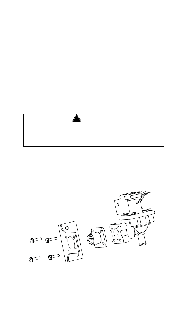
Water Inlet Valve
The water inlet valve normally does not require
removal for cleaning. Refer to “Water System
Checklist” page 98, if you are troubleshooting water
related problems.
1. When the ice machine is off, the water inlet valve
must completely stop water flow into the machine.
Watch for water flow.
When the ice machine is on, the water inlet valve must
allow the proper water flow through it. Set the toggle
switch to ON. Watch for water flow into the ice
machine. If the water flow is slow or only trickles into
the ice machine, refer to water system checklist.
Follow the procedure below to remove the water inlet
valve.
1. Remove the 1/4” hex head screws.
2. Remove, clean, and install the filter screen.
!
Warning
Disconnect the electric power to the ice machine
and dispenser at the electric service switch box and
turn off the water supply before proceeding.
4 Hex Head
Screws
46 Part Number 8014793 6/18
Water Dump Valve
The water dump valve normally does not require
removal for cleaning. To determine if removal is
necessary:
1. Locate the water dump valve.
2. Set the toggle switch to ICE.
3. While the ice machine is in the freeze mode,
check the water trough to determine if the dump
valve is leaking. If there is no or little water in the
water trough (during the freeze cycle) the dump
valve is leaking.
A. If the dump valve is leaking, replace the
dump valve.
B. If the dump valve is not leaking, follow the
“Ice Machine Cleaning Procedure”.
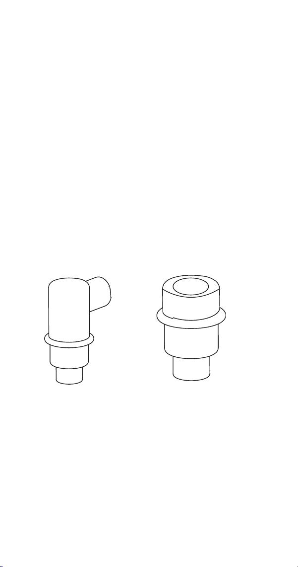
Drain Line Check Valve
The drain line check valve (not used on all models)
should be inspected and cleaned, whenever the ice
machine is cleaned.
1. Remove check valve and tube assembly.
A. Tip assembly to right until tubing disengages.
B. Lift up on assembly to remove.
2. Remove insulation from check valve assembly.
3. Remove vinyl tubing from top of check valve.
4. Soak in cleaner solution 10 minutes, and then
flush with water to remove debris.
CHECK VALVE
ASSEMBLY
CHECK VALVE

Part Number 8014793 6/18 47
Removal from Service/Winterization
General
Special precautions must be taken if the ice machine is
to be removed from service for an extended period of
time or exposed to ambient temperatures of 32°F
(0°C) or below.
Follow the applicable procedure below.
SELF-CONTAINED AIR-COOLED ICE MACHINES
1. Move the ICE/OFF/CLEAN switch to OFF.
2. Disconnect the electric power at the circuit
breaker or the electric service switch.
3. Turn off the water supply.
4. Remove the water from the water trough.
5. Disconnect and drain the incoming ice-making
water line at the rear of the ice machine.
6. Energize the ice machine and wait one minute for
the water inlet valve to open.
7. Blow compressed air in both the incoming water
and the drain openings in the rear of the ice
machine until no more water comes out of the
water inlet lines or the drain.
8. Make sure water is not trapped in any of the water
lines, drain lines, distribution tubes, etc.
!
Caution
If water is allowed to remain in the ice machine in
freezing temperatures, severe damage to some
components could result. Damage of this nature is
not covered by the warranty.
48 Part Number 8014793 6/18
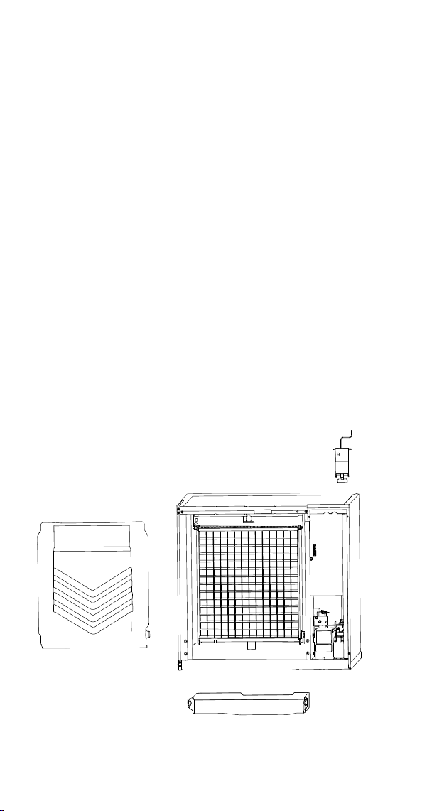
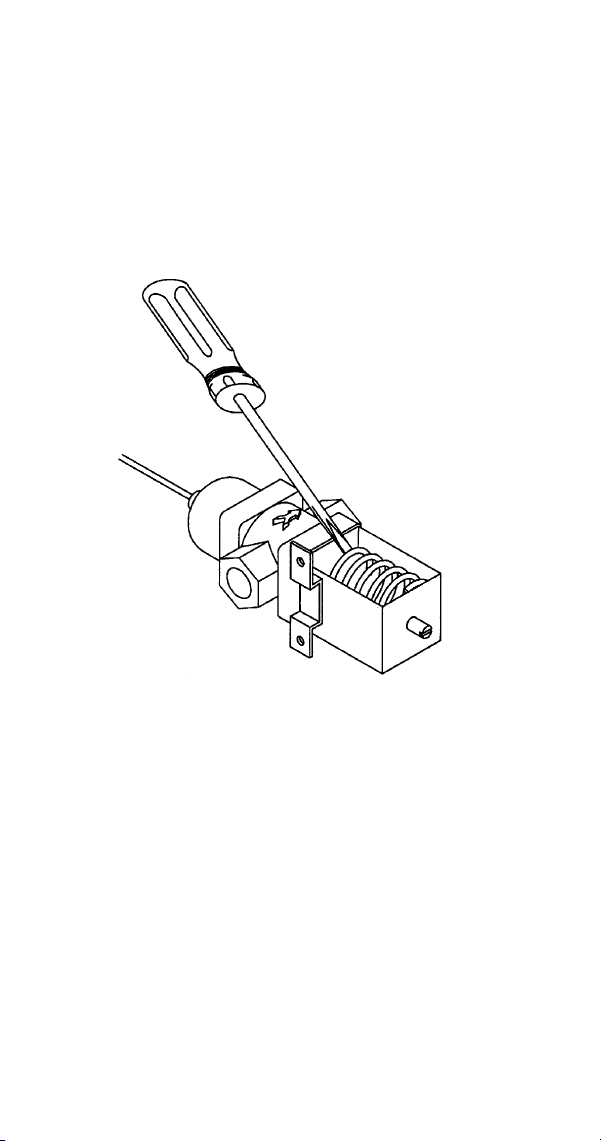
WATER-COOLED ICE MACHINES
1. Perform steps 1-6 under “Self-Contained Air-
Cooled Ice Machines.”
2. Disconnect the incoming water and drain line from
the water-cooled condenser.
3. Insert a large screwdriver between the bottom
spring coils of the water regulating valve. Pry
upward to open the valve.
4. Hold the valve open and blow compressed air
through the condenser until no water remains.
REMOTE ICE MACHINES
1. Move the ICE/OFF/CLEAN switch to OFF.
2. “Frontseat” (shut off) the receiver service valve.
Hang a tag on the switch as a reminder to open
the valves before restarting.
3. Perform steps 1-6 under “Self-Contained Air-
Cooled Ice Machines.”
SV1624

Part Number 8014793 6/18 49
Sequence of Operation
Self Contained Air or Water Cooled
SINGLE & QUAD EVAPORATOR MODELS
NOTE: The toggle switch must be in the ice position
and the water curtain/ice dampers must be in place on
the evaporator before the ice machine will start.
Initial Start-Up or Start-Up After
Automatic Shut-Off
1. Water Purge
Before the refrigerant compressor starts, the water
pump and water dump solenoid energize to purge the
ice machine of old water. This feature ensures that the
ice making cycle starts with fresh water.
Single evaporator models energize the harvest
valve(s) and air compressor (when used) at the end of
the water purge and they remain energized during
refrigeration startup.
Energized Control Board Lights-
Single Evaporators = Left Bin (green)
Quad Evaporators = All Curtain Switches (green),
Dump Valve (red), Water Pump (red)
2. Refrigeration System Start-Up
The compressor, condenser fan motor and water fill
valve energize and 5 seconds later the harvest
valve(s) and air compressor(s) de-energize.
The fan motor is wired through a fan cycle pressure
control and will cycle on and off when the room
temperatures is below 70°F (21°C) .
Energized Control Board Lights-
Single Evaporators = Left Bin (green)
Quad Evaporators = All Curtain Switches (green),
Water Solenoid (red), Liquid Solenoid (red)

50 Part Number 8014793 6/18
Freeze Sequence
3. Prechill
The compressor lowers the temperature of the
evaporator(s) before the water pump is energized. The
water fill valve will remain energized until water
contacts the water level probe.
Energized Control Board Lights-
Single Evaporators = Left Bin (green)
Quad Evaporators = All Curtain Switches (green),
Water Solenoid (red), Liquid Solenoid (red)
4. Freeze
The water pump(s) energizes and water flows over the
evaporator. After water contacts the water level probe
the water fill valve de-energizes. The water fill valve
will cycle on and off one more time.
The freeze cycle continues until the six minute freeze
lock expires and enough ice has formed to allow water
to contact the ice thickness probe. After approximately
10 seconds of continual water contact, the harvest
sequence is initiated.
NOTE: Freeze lock is bypassed after moving the
toggle switch from OFF to ICE position for the first
cycle only.
Energized Control Board Lights-
Single Evaporators = Left Bin (green), water probe
(green), Harvest (red when water contacts the ice
thickness probe)
Quad Evaporators = All Curtain Switches (green),
Water Level (green), Water Solenoid (red), Liquid
Solenoid (red), Water Pump (red), Harvest (red when
water contacts the ice thickness probe)

Part Number 8014793 6/18 51
Harvest Sequence
5. Water Purge
The air compressor (when used) and the harvest
valve(s) open at the beginning of the water purge to
divert hot refrigerant gas into the evaporator.
The water pump continues to run, and the water dump
valve energizes to purge the water in the water trough.
Single evaporator models energize the water fill valve
for the last 15 seconds of the water purge cycle.
Energized Control Board Lights-
Single Evaporators = Left Bin (green), Harvest (red)
Quad Evaporators = All Curtain Switches (green),
Liquid Solenoid (red), Dump Valve (red), Water Pump
(red), Harvest (red), All Harvest Valves (red)

52 Part Number 8014793 6/18
6. Harvest
The air compressor (when used) remains energized
and the harvest valve(s) remains open. The refrigerant
gas warms the evaporator causing the cubes to slide,
as a sheet, off the evaporator and into the storage bin.
Energized Control Board Lights-
Single Evaporators = Left Bin (green), Harvest (red)
Quad Evaporators = All Curtain Switches (green),
Liquid Solenoid (red), Harvest (red), All Harvest Valves
(red)
Single evaporator models - The sliding sheet of
cubes opens the water curtain and bin switch.
The momentary opening and re-closing of the bin
switch terminates the harvest sequence and return to
the freeze sequence (Step 3 - 4.)
Quad evaporator models - The sliding sheet of
cubes opens the ice damper and bin switch. The
momentary opening and re-closing of the bin switch
de-energized the harvest valve for the evaporator.
When all of the bin switches have opened and closed
the ice machine will terminate the harvest sequence
and return to the freeze sequence (Step 3 - 4.)
Energized Control Board Lights (once ice drops)-
Single Evaporators = Left Bin (green flashes once)
Quad Evaporators = All Curtain Switches (green
flashes once), Liquid Solenoid (red)

Part Number 8014793 6/18 53
Automatic Shut-Off
7. Automatic Shut-Off
When the storage bin is full at the end of a harvest
sequence, the sheet of cubes fails to clear the water
curtain/ice damper and will hold it open. After the
water curtain/ice damper is held open for 30 seconds,
the ice machine shuts off. The ice machine remains off
for 3 minutes before it can automatically restart.
The ice machine remains off until enough ice has been
removed from the storage bin to allow the ice to fall
clear of the water curtain or all of the ice dampers. As
the water curtain/ice dampers swing back to the
closed position, the bin switch re-closes and the ice
machine restarts (steps 1 - 2), provided the 3 minute
delay period is complete.
Energized Control Board Lights-
Single Evaporators = No Lights
Quad Evaporators = Depending on which damper is
open, the closed dampers will be lit (green)

54 Part Number 8014793 6/18
Safety Timers
The control board has the following non-adjustable
safety timers:
• The ice machine is locked into the freeze cycle for
6 minutes before a harvest cycle can be initiated.
Freeze lock is bypassed after moving the toggle
switch from OFF to ICE position for the first cycle
only.
• The maximum freeze time is 60 minutes at which
time the control board automatically initiates a
harvest sequence (steps 5 & 6).
• The maximum harvest time is 3.5 minutes for
single evaporators and 7 minutes for Quad
evaporator model. The control board automatically
initiates a freeze sequence (steps 3 & 4) when
these times are exceeded.

Part Number 8014793 6/18 55
Safety Limits
Safety limits are stored and indicated by the control
board after three cycles. The number of cycles
required to stop the ice machine varies for each safety
limit.
• Safety Limit 1 - If the freeze time reaches 60
minutes, the control board automatically initiates a
harvest cycle. If 6 consecutive 60-minute freeze
cycles occur, the ice machine stops
• Safety Limit 2 single evaporator models - If the
harvest time reaches 3.5 minutes, the control
board automatically returns the ice machine to the
freeze cycle. If 500 consecutive 3.5 minute harvest
cycles occur, the ice machine stops.
• Safety Limit 2 Quad evaporator models - If the
harvest time reaches 7 minutes, the control board
automatically returns the ice machine to the freeze
cycle. If 500 consecutive 7 minute harvest cycles
occur, the ice machine stops.
• Safety Limit 3 Quad evaporator models - If the low
refrigerant pressure control opens, the ice
machine shuts off and starts a 5 minute delay
period. If 3 consecutive low pressure esvents
occur the ice machine stops and flashes the
safety/harvest light.
Use the following procedures to determine if the
control board contains a safety limit indication.
1. Move the toggle switch to OFF.
2. Move the toggle switch back to ICE. Watch the
safety limit/harvest lights on the control board. If a
safety limit has been recorded, the corresponding
light will flash once, twice or three times to
indicate which safety limit stopped the ice
machine.

56 Part Number 8014793 6/18
Safety Limit Stand-By Mode
(Quad Evaporators Only)
The first time a safety limit shut down occurs, (three
consecutive long freeze or harvest cycles) the ice
machine will turn off for 60 minutes (Stand-By Mode).
During the Stand-By Mode the harvest light will be
flashing continuously and a safety limit indication can
be viewed. After 60 minutes the ice machine will
automatically restart to see if the problem re-occurs. If
the same safety limit is reached a second time (three
more consecutive long freeze or harvest cycles) the
ice machine will initiate a safety limit shut down and
remain off until it is manually restarted. During a safety
limit shut down the harvest light will be flashing
continuously.

Part Number 8014793 6/18 57
Warm Water Rinse Cycle
Single evaporator models only - Closing the back of
the evaporator allows ice to build up on the rear of the
evaporator and the plastic evaporator frame parts.
After 200 freeze/harvest cycles have been completed
the control board will initiate a warm water rinse.
After the 200th harvest cycle ends:
• The Clean and Harvest LEDs energize to indicate
the ice machine is in a warm water rinse.
• The compressor and harvest valve remain
energized.
• The water pump energizes.
• The water inlet valve energizes until water
contacts the water level probe.
• The compressor and harvest valve warm the water
for 5 minutes, then de-energize.
• The water pump remains energized for an
additional 5 minutes (10 minute total on time) then
de-energizes.
NOTE: The warm water rinse cycle can be terminated
by moving the toggle switch to the OFF position, then
back to ICE.

58 Part Number 8014793 6/18
Self Contained Air & Water-Cooled
Single Evaporator Model Energized Parts Chart
Ice Making
Sequence of
Operation
Water
Pump
Harvest
Valve(s)
Air
Pump(s)*
Water
Inlet
Valve
Water
Dump
Valve
Contactor
Coil
Compressor
Condenser
Fan Motor
Length
of Time
Start-Up
1. Water Purge
On On
35 sec.
Off
10 sec.
On
Off On Off Off Off
45 Seconds
2. Refrigeration
System Start-up
Off On Off On Off On On
May Cycle
On/Off
5 Seconds
Freeze Sequence
3. Prechill
Off Off Off
May
Cycle
On/Off
during
pre-chill
Off On On
May Cycle
On/Off
Initial Start-Up is
60 Seconds
30 Seconds thereafter
4. Freeze
On Off Off
Cycles
Off then
On one
more
time
Off On On
May Cycle
On/Off
Unil 10 Sec.
Water Contact
w/Ice Thickness Probe
Part Number 8014793 6/18 59
Harvest Sequence
5. Water Purge
On On On
30 sec.
Off
15 sec.
On
On On On
May Cycle
On/Off
Factory
Set at
45 Seconds
6. Harvest
Off On On Off Off On On
May Cycle
On/Off
Bin Switch
Activation
7. Automatic
Shut-Off
Off Off Off Off Off Off Off Off
Until Bin Switch
Re-closes & 3 min.
delay
* NOT USED ON ALL MODELS
Self Contained Air & Water-Cooled
Single Evaporator Model Energized Parts Chart (Continued)
Ice Making
Sequence of
Operation
Water
Pump
Harvest
Valve(s)
Air
Pump(s)*
Water
Inlet
Valve
Water
Dump
Valve
Contactor
Coil
Compressor
Condenser
Fan Motor
Length
of Time

60 Part Number 8014793 6/18
Self Contained Water-Cooled
Quad Evaporator Model Energized Parts Chart
Ice Making
Sequence of
Operation
Water
Pumps
Harvest
Valves
Air
Pumps
Water
Inlet Valve
Water
Dump
Valves
Contactor
Coil
Compressor
Length
of Time
Start-Up
1. Water Purge
On Off Off Off On Off Off
Initial Start-Up is
45 Seconds
30 Seconds thereafter
2. Refrigeration
System Start-up
Off Off Off On Off On On
5 Seconds
Freeze Sequence
3. Prechill
Off Off Off
May Cycle
On/Off
during
pre-chill
Off On On
30 Seconds thereafter
4. Freeze
On Off Off
Cycles Off
then On
up to two
more
times
Off On On
Unil 10 Sec.
Water Contact
w/Ice Thickness Probe

Part Number 8014793 6/18 61
Harvest Sequence
5. Water Purge
On On On
On
from 30-45
seconds
On On On
Factory
Set at
30 Seconds
6. Harvest
Off On On Off Off On On
Bin Switch
Activation
7. Automatic
Shut-Off
Off Off Off Off Off Off Off
Until Bin Switch
Re-closes & 3 min. delay
expires
Self Contained Water-Cooled
Quad Evaporator Model Energized Parts Chart (Continued)
Ice Making
Sequence of
Operation
Water
Pumps
Harvest
Valves
Air
Pumps
Water
Inlet Valve
Water
Dump
Valves
Contactor
Coil
Compressor
Length
of Time

62 Part Number 8014793 6/18
REMOTES
Single Evaporator Models
NOTE: The toggle switch must be in the ice position
and the water curtain must be in place on the
evaporator before the ice machine will start.
Initial Start-Up or Start-Up After
Automatic Shut-Off
1. Water Purge
Before the compressor starts, the water pump and
water dump solenoid are energized for 45 seconds, to
completely purge the ice machine of old water. This
feature ensures that the ice making cycle starts with
fresh water.
The harvest valve and harvest pressure regulating
(HPR) solenoid valves also energize during water
purge, although they stay on for an additional 5
seconds (50 seconds total on time) during the initial
refrigeration system start-up.
When Used - The air pump energizes for the last 10
seconds of the cycle.
Energized Control Board Lights-
Left Bin (green)

Part Number 8014793 6/18 63
2. Refrigeration System Start-Up
The compressor and liquid line solenoid valve
energize after the 45 second water purge and remain
on throughout the entire Freeze and Harvest
Sequences. The water fill valve is energized at the
same time as the compressor. It remains on until the
water level sensor closes for 3 continuous seconds, or
until a six-minute time period has expired. The harvest
valve and HPR solenoid valves remain on for 5
seconds during initial compressor start-up and then
shut off.
The remote condenser fan motor starts at the same
time the compressor starts and remains on throughout
the entire Freeze and Harvest Sequences.
Energized Control Board Lights-
Left Bin (green)

64 Part Number 8014793 6/18
Freeze Sequence
3. Prechill
The compressor is on for 30 seconds (60 seconds
initial cycle) prior to water flow, to prechill the
evaporator.
Energized Control Board Lights-
Left Bin (green)
4. Freeze
The water pump restarts after the prechill. An even
flow of water is directed across the evaporator and into
each cube cell, where it freezes. The water fill valve
will cycle on and then off one more time to refill the
water trough.
When sufficient ice has formed, the water flow (not the
ice) contacts the ice thickness probe. After
approximately 10 seconds of continual water contact,
the harvest sequence is initiated. The ice machine
cannot initiate a harvest sequence until a 6 minute
freeze lock has been surpassed.
Energized Control Board Lights-
Left Bin (green), water probe (green), Harvest (red
when water contacts the ice thickness probe)

Part Number 8014793 6/18 65
Harvest Sequence
5. Water Purge
The water pump continues to run, and the water dump
valve energizes for 45 seconds to purge the water in
the sump trough. The water fill valve energizes (turns
on) and de-energizes (turns off) strictly by time. The
water fill valve energizes for the last 15 seconds of the
45-second water purge. The water purge must be at
the factory setting of 45 seconds for the fill valve to
energize during the last 15 seconds of the Water
Purge. If set at less than 45 seconds the water fill
valve does not energize during the water purge.
After the 45 second water purge, the water fill valve,
water pump and dump valve de-energize. (Refer to
“Water Purge Adjustment”) The harvest valve(s) and
HPR solenoid valve also open at the beginning of the
water purge.
Energized Control Board Lights-
Left Bin (green), Harvest (red)
6. Harvest
The HPR valve and the harvest valve(s) remain open
and the refrigerant gas warms the evaporator causing
the cubes to slide, as a sheet, off the evaporator and
into the storage bin. The sliding sheet of cubes swings
the water curtain out, opening the bin switch. The
momentary opening and re-closing of the bin switch
terminates the harvest sequence and returns the ice
machine to the freeze sequence (Step 3 - 4.)
When Used - The air pump energizes after 35 seconds
and remains energized throughout the entire harvest
cycle. The air pump will automatically energize after
60 seconds when the harvest cycle time exceeded 75
seconds the previous cycle
Energized Control Board Lights-
Left Bin (green), Harvest (red) - when the ice drops the
harvest light turns off

66 Part Number 8014793 6/18
Automatic Shut-Off
7. Automatic Shut-Off
When the storage bin is full at the end of a harvest
sequence, the sheet of cubes fails to clear the water
curtain and will hold it open. After the water curtain is
held open for 30 seconds, the ice machine shuts off.
The ice machine remains off for 3 minutes before it
can automatically restart.
The ice machine remains off until enough ice has been
removed from the storage bin to allow the ice to drop
clear of the water curtain. As the water curtain swings
back to the operating position, the bin switch re-closes
and the ice machine restarts (steps 1 - 2) provided the
3 minute delay period is complete.
Energized Control Board Lights-
No Lights

Part Number 8014793 6/18 67
Remote Air-Cooled
Single Evaporator Model Energized Parts Chart
Ice Making
Sequence of
Operation
Water
Pump
Harvest
Valve
(Left)
HPR
Valve
Harvest
Valve
(Right)
(When
Used)
Air
Comp.
(When
Used)
Water
Inlet
Valve
Water
Dump
Valve
Contactor
Coil
Liquid Line
Solenoid
Compressor
Condenser
Fan Motor
Length
of Time
Initial Start-Up
1. Water Purge
On On On
35 sec.
Off
10 sec.
On.
Off On Off Off Off
45 Seconds
2. Refrigeration
System Start-
up
Off On On On On Off On On On
5 Seconds
Freeze Sequence
3. Prechill
Off Off Off Off
May
Cycle
On/Off
during
prechill
Off On On On
Initial Start-Up is
60 Seconds
30 Seconds thereafter
4. Freeze
On Off Off Off
Cycles
Off
Then On
one
more
time
Off On On On
Unil 10 Sec.
Water Contact
w/Ice Thickness Probe

68 Part Number 8014793 6/18
Harvest Sequence
5. Water Purge
On On On
On
After
35 sec.
30 sec.
Off
15 sec.
On
On On On On
Factory
Set at
45 Seconds
6. Harvest Off On On On Off Off On On On
Bin Switch
Activation
7. Automatic
Shut-Off
Off Off Off Off Off Off Off Off Off
Until Bin Switch
Re-closes & 3 min.
delay
Remote Air-Cooled
Single Evaporator Model Energized Parts Chart (Continued)
Ice Making
Sequence of
Operation
Water
Pump
Harvest
Valve
(Left)
HPR
Valve
Harvest
Valve
(Right)
(When
Used)
Air
Comp.
(When
Used)
Water
Inlet
Valve
Water
Dump
Valve
Contactor
Coil
Liquid Line
Solenoid
Compressor
Condenser
Fan Motor
Length
of Time

Part Number 8014793 6/18 69
Troubleshooting
Safety Limits
In addition to standard safety controls, the control
board has built in safety limit controls which protect the
ice machine from major component failures.
Use the following procedures to determine if the
control board contains a safety limit indication.
1. Move the toggle switch to OFF.
2. Move the toggle switch back to ICE.
3. Watch the safety limit lights/harvest light on the
control board. If a safety limit has been recorded,
the corresponding light will flash once, twice or
three times to indicate which safety limit stopped
the ice machine.
Safety limits are stored and indicated by the control
board after three cycles. The number of cycles
required to stop the ice machine varies for each safety
limit.
• Safety Limit 1 all models - If the freeze time
reaches 60 minutes, the control board
automatically initiates a harvest cycle. If 6
consecutive 60-minute freeze cycles occur, the ice
machine stops
• Safety Limit 2 single evaporator models - If the
harvest time reaches 3.5 minutes, the control
board automatically returns the ice machine to the
freeze cycle. If 500 consecutive 3.5 minute harvest
cycles occur, the ice machine stops.
• Safety Limit 2 quad evaporator models - If the
harvest time reaches 7 minutes, the control board
automatically returns the ice machine to the freeze
cycle. If 500 consecutive 7 minute harvest cycles
occur, the ice machine stops.
• Safety Limit 3 quad evaporator models - If the
low refrigerant pressure control opens, the ice
machine shuts off and starts a 5 minute delay
period. If 3 consecutive low pressure events occur
the ice machine stops and flashes the harvest
light.

70 Part Number 8014793 6/18
QUAD EVAPORATOR MACHINES ONLY
When a safety limit condition causes the ice machine
to stop, the harvest light on the control board
continually flashes on and off. Use the following
procedures to determine which safety limit has
stopped the ice machine.
1. Move the toggle switch to OFF.
2. Move the toggle switch back to ICE.
3. Watch the harvest light. It will flash one or two
times, corresponding to safety limits 1 and 2, to
indicate which safety limit stopped the ice
machine.
After safety limit indication, the ice machine will restart
and run until a safety limit is exceeded again.
When a safety limit condition is exceeded for 3
consecutive cycles the control board enters the limit to
memory and the ice machine continues to run. Use the
following procedure to determine if the control board
contains a safety limit indication.
1. Move the toggle switch to OFF.
2. Move the toggle switch back to ICE.
3. Watch the harvest light. It will flash one or two
times, corresponding to safety limits 1 and 2, to
indicate which safety limit stopped the ice
machine.
When a safety limit condition is exceeded (6
consecutive cycles for safety limit #1 or 500 cycles for
safety limit #2) the ice machine stops, and the harvest
light on the control board flashes on and off. Use the
following procedure to determine which safety limit
has stopped the ice machine.
1. Move the toggle switch to OFF.
2. Move the toggle switch back to ICE.
3. Watch the harvest light. It will flash one or two
times, corresponding to safety limits 1 and 2, to
indicate which safety limit stopped the ice
machine.
After safety limit indication, the ice machine will restart
and run until a safety limit is exceeded again.

Part Number 8014793 6/18 71
Safety Limit Stand-By Mode:
The first time a safety limit shut down occurs, (three
consecutive long freeze or harvest cycles) the ice
machine will turn off for 60 minutes (Stand-By Mode).
During the Stand-By Mode the harvest light will be
flashing continuously and a safety limit indication can
be viewed. After 60 minutes the ice machine will
automatically restart to see if the problem re-occurs. If
the same safety limit is reached a second time (three
more consecutive long freeze or harvest cycles) the
ice machine will initiate a safety limit shut down and
remain off until it is manually restarted. During a safety
limit shut down the harvest light will be flashing
continuously.

72 Part Number 8014793 6/18
ANALYZING WHY A SAFETY LIMIT STOPPED THE
ICE MACHINE
According to the refrigeration industry, a high
percentage of compressors fail as a result of external
causes. These can include: flooding or starving
expansion valves, dirty condensers, water loss to the
ice machine, etc. The safety limits protect the ice
machine (primarily the compressor) from external
failures by stopping ice machine operation before
major component damage occurs.
The safety limit system is similar to a high pressure
cut-out control. It stops the ice machine, but does not
tell what is wrong. The service technician must
analyze the system to determine what caused the high
pressure cut-out, or a particular safety limit, to stop the
ice machine.
The safety limits are designed to stop the ice machine
prior to major component failures, most often a minor
problem or something external to the ice machine.
This may be difficult to diagnose, as many external
problems occur intermittently.
Example: An ice machine stops intermittently on safety
limit #1 (long freeze times). The problem could be a
low ambient temperature at night, a water pressure
drop, the water is turned off one night a week, etc.
Refrigeration and electrical component failures will
cause a safety limit trip. Eliminate all electrical
components and external causes first. If it appears
that the refrigeration system is causing the problem,
use Manitowoc’s Freeze Cycle Refrigeration System
Operational Analysis Table, along with detailed charts,
checklists, and other references to determine the
cause.
The following checklists are designed to assist the
service technician in analysis. However, because
there are many possible external problems, do not
limit your diagnosis to only the items listed.

Part Number 8014793 6/18 73
SAFETY LIMIT #1
Water System
1. Water supply to machine is being interrupted
2. Water leaking down the drain during freeze (dump
valve or water tracking into condensate tray)
3. Water tracking into bin
4. Uneven water flow over evaporator
5. Water pump not pumping
Electrical System
1. Improper voltage (low)
2. Ice thickness probe adjustment too thick
3. Water level probe open / dirty
4. Water inlet valve failure
5. Contactor failure
6. Compressor failure / start component failure
page 134
Refrigeration System
1. Dirty condenser
2. Low on Refrigerant
3. Starving TXV
4. Head Pressure Control Valve stuck in Bypass
5. Harvest valve leaking through or stuck open
6. Inefficient compressor

74 Part Number 8014793 6/18
SAFETY LIMIT #2
Water System
1. Ice thickness control probe is dirty causing a
premature harvest with no ice on the plate.
page 137
2. Dirty evaporator causing a long harvest and ice
melt out. page 120
Electrical System
1. Ice thickness probe adjustment too close
2. Bin switch failed closed
3. Harvest valve not energizing
4. Quad Evaporator Only - Harvest pressure
solenoid valve not energizing.
Refrigeration System
1. Non-Manitowoc components
2. Incorrect refrigerant charge
3. TXV flooding
4. Defective harvest valve
5. Defective fan cycle control - will not open
(page 156)
6. Defective Head Pressure Control Valve - will not
bypass (page 153)
7. Quad Evaporator Only - Harvest pressure
solenoid valve not energizing.

Part Number 8014793 6/18 75
SAFETY LIMIT #3
Water System
1. Water supply to machine is being interrupted
2. Water leaking down the drain during freeze (dump
valve or water tracking into condensate tray)
3. Water tracking into bin
4. Uneven water flow over evaporator
5. Water pump not pumping
Electrical System
1. Water level probe prematurely satisfied
2. Water inlet valve failure
3. Water pump failure
Refrigeration System
1. Low on Refrigerant
2. Starving TXV

76 Part Number 8014793 6/18
Control Board Testing
All replacement S Model control boards and ice
machines with serial numbers larger than 110924847
have a control board that includes a diagnostic test
cycle. The control board can be identified by the blue
printed circuit board and a push button switch on the
bottom left corner labeled “service mode”.
CONTROL BOARD TEST CYCLE
1. Place the toggle switch in the ice position.
2. Press and hold the test button for 5 seconds.
3. The control board memory is cleared.
A. All safety limits are cleared
B. Resets to factory default settings
C. Calibration is cleared for ice thickness &
water level probe.
4. The control board relays close at 1 second
intervals and energize the corresponding control
board light.
5. The relays remain closed and the lights remain
energized for 3.5 minutes to allow time to test
voltage at components.
6. After 3.5 minutes the ice machine automatically
exits the test cycle.
7. An ice making cycle will automatically start
(unless the toggle switch is moved to OFF).
8. Water level and ice thickness probe calibration
are processed and stored in control board
memory during the second
ice making cycle.
The test cycle can be terminated at anytime by moving
the toggle switch from ICE to OFF, or by disconnecting
and reapplying line voltage to the ice machine.

Part Number 8014793 6/18 77
Troubleshooting By Symptom
The troubleshooting procedures follow flow charts.
There are four symptoms, the symptom that you are
experiencing will determine which flow chart to use.
The flow chart asks yes and no questions to determine
the problem. The flow chart will direct you to a
procedure to correct the problem. Traditional remote
and self contained models use separate charts.
SYMPTOM #1
Ice Machine Stops Running
Toggle Switch is in the ICE position
or
Has a History of Shutting Down
• Refer to Ice Machine Stops Running Flow Chart
(page 78)
SYMPTOM #2
Ice Machine has a Long Freeze Cycle.
Ice Formation is Thick
or
Thin Ice Fill on Top or Bottom of Evaporator
or
Low Production
Safety Limit #1 (possible)
• Refer to Freeze Cycle Refrigeration System
Operational Analysis Table
(page 94)
SYMPTOM #3
Ice Machine Will Not Harvest - Freeze Cycle is
Normal and Ice Cubes are Not Melted After Harvest
Safety Limit #2 (possible)
• Refer to Refrigeration Harvest Flow Chart
(page 116)
Symptom #4
Ice Machine Will Not Harvest - Freeze Cycle is
Normal and Ice Cubes are Melted After Harvest
• Refer to Ice Melt out Flow Chart
(page 120)
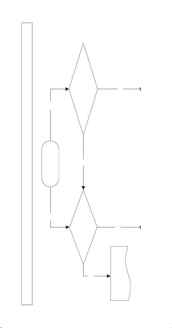
78 Part Number 8014793 6/18
SYMPTOM #1 ICE MACHINE WILL NOT RUN
Ice Machine Stops Running or Has a History of Shutting Down
YES
YES
NO
NO
YES
NO
Control board has
energized lights?
Does ice machine run in CLEAN?
Does the
ice machine start when toggle switch is
moved to ICE?
Refer to
“Diagnosing an
Ice Machine that Will Not Run”
Continued on Next Page...
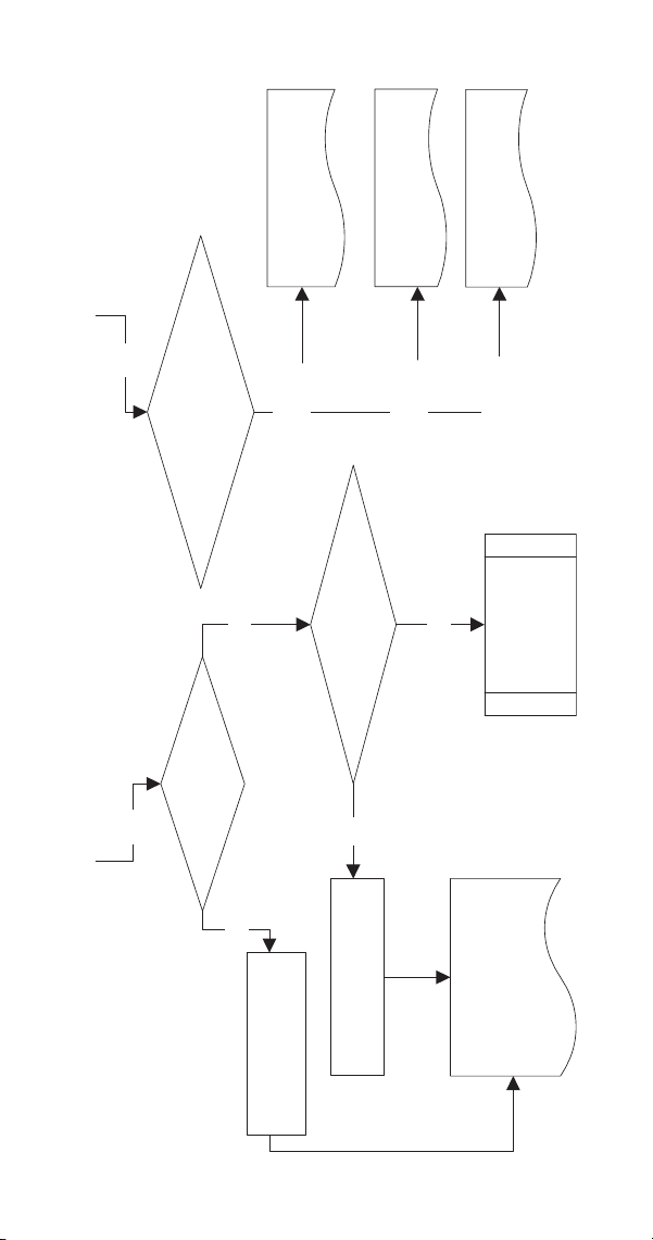
Part Number 8014793 6/18 79
YES
YES
NO
NO
Are
Water Curtain/Ice Dampers
in place?
YES
YES
SL1/
Harvest (once)
Run machine &
check for
Normal Operation
Refer to Bin
Switch Diagnostics
Are
Water Curtain/Ice Damper
magnets attached?
Install
Water Curtain/
Ice Dampers
Replace the Water Curtain/
Ice Dampers
SL2/
Harvest (twice)
Harvest (3 times)
Which light flashed immediately after
resetting the toggle switch?
Refer to Safety Limit #1
Long Freeze Cycle
Refer to Safety Limit #2
Long Harvest Cycle
Refer to Safety Limit #3
Low Pressure

80 Part Number 8014793 6/18
DIAGNOSING AN ICE MACHINE THAT WILL NOT
RUN
1. Verify primary voltage is supplied to ice machine
and the fuse/circuit breaker is closed.
2. Verify the High Pressure cutout is closed. The
HPCO is closed if primary power voltage is
present at terminals #55 and #56 on the control
board.
3. Verify control board fuse is okay. If the bin switch
or water level probe light functions, the fuse is
okay.
4. Verify all bin switches function properly. A
defective bin switch can falsely indicate a full bin
of ice.
5. Verify ICE/OFF/CLEAN toggle switch functions
properly. A defective toggle switch may keep the
ice machine in the OFF mode.
6. Verify low DC voltage is properly grounded. Loose
DC wire connections may intermittently stop the
ice machine on a safety limit.
7. Replace the control board. Be sure steps 1-6
were followed thoroughly. Intermittent problems
are not usually related to the control board.
!
Warning
High (line) voltage is applied to the control board
(terminals #55 and #56) at all times. Removing
control board fuse or moving the toggle switch to
OFF will not remove the power supplied to the
control board.

Part Number 8014793 6/18 81
COMPRESSOR ELECTRICAL DIAGNOSTICS
The compressor does not start or will trip repeatedly
on overload.
Check Resistance (Ohm) Values
NOTE: Compressor windings can have very low ohm
values. Use a properly calibrated meter.
Perform the resistance test after the compressor
cools. The compressor dome should be cool enough
to touch (below 120°F/49°C) to assure that the
overload is closed and the resistance readings will be
accurate.
SINGLE PHASE COMPRESSORS
1. Disconnect power then remove the wires from the
compressor terminals.
2. The resistance values between C and S and
between C and R, when added together, should
equal the resistance value between S and R.
3. If the overload is open, there will be a resistance
reading between S and R, and open readings
between C and S and between C and R. Allow the
compressor to cool, then check the readings
again.
THREE PHASE COMPRESSORS
1. Disconnect power and remove the wires from the
compressor terminals.
2. The resistance values between L1 and L2,
between L2 and L3, and between L3 and L1
should all be equal.
3. If the overload is open, there will be open
readings between L1 and L2, between L2 and L3,
and between L3 and L1. Allow the compressor to
cool, then check the readings again.

82 Part Number 8014793 6/18
CHECK MOTOR WINDINGS TO GROUND
Check continuity between all three terminals and the
compressor shell or copper refrigeration line. Scrape
metal surface to get good contact. If continuity is
present, the compressor windings are grounded and
the compressor should be replaced.
COMPRESSOR DRAWING LOCKED ROTOR
To determine if the compressor is seized, check the
amp draw while the compressor is trying to start.
The two likely causes of this are a defective starting
component and a mechanically seized compressor.
To determine which you have:
1. Install high and low side gauge set.
2. Try to start the compressor.
3. Watch the pressures closely.
A. If the pressures do not move, the compressor
is seized. Replace the compressor.
B. If the pressures move, the compressor is
turning slowly and is not seized. Check the
capacitors and relay.
COMPRESSOR DRAWING HIGH AMPS
The continuous amperage draw on start-up should not
be near the maximum fuse size indicated on the serial
tag.

Part Number 8014793 6/18 83
SYMPTOM #2 LOW PRODUCTION, LONG FREEZE
Ice Machine has a Long Freeze Cycle.
Ice Formation is Thick
or
Thin Ice Fill on Top or Bottom of Evaporator
or
Low Production
How to Use the Freeze Cycle Refrigeration System
Operational Analysis Table
GENERAL
These tables must be used with charts, checklists and
other references to eliminate refrigeration components
not listed on the tables and external items and
problems which can cause good refrigeration
components to appear defective.
The tables list five different defects that may affect the
ice machine’s operation.
NOTE: A low-on-charge ice machine and a starving
expansion valve have very similar characteristics and
are listed under the same column.
NOTE: Before starting, see “Before Beginning
Service” for questions to ask when talking to the ice
machine owner.

84 Part Number 8014793 6/18
PROCEDURE
Step 1 Complete the “Operation Analysis”
column.
Read down the left “Operational Analysis” column.
Perform all procedures and check all information
listed. Each item in this column has supporting
reference material to help analyze each step.
While analyzing each item separately, you may find an
“external problem” causing a good refrigerant
component to appear bad. Correct problems as they
are found. If the operational problem is found, it is not
necessary to complete the remaining procedures.
Step 2 Enter check marks (
).
Each time the actual findings of an item in the
“Operational Analysis” column matches the published
findings on the table, enter a check mark.
Example: Freeze cycle suction pressure is determined
to be low. Enter a check mark in the “low” column.
Step 3 Add the check marks listed under each of
the four columns. Note the column number with
the highest total and proceed to “Final Analysis.”
NOTE: If two columns have matching high numbers,
a procedure was not performed properly, supporting
material was not analyzed correctly or the problem
component is not covered by the analysis table.
Part Number 8014793 6/18 85
SYMPTOM #2 - FREEZE CYCLE REFRIGERATION SYSTEM OPERATIONAL ANALYSIS TABLES
S MODELS SINGLE EXPANSION VALVE
Operational Analysis 1 2 3 4
Ice Production
Air-Temperature Entering Condenser_____________
Water Temperature Entering Ice Machine_________
Published 24 hour ice production________________
Calculated (actual) ice production_______________
NOTE: The ice machine is operating properly if the ice fill patterns is normal and ice
production is within 10% of charted capacity.
Installation and Water
System
All installation and water related problems must be corrected before proceeding with chart.
Ice Formation Pattern
Ice formation is extremely
thin on outlet of
evaporator
-or-
No ice formation on the
entire evaporator
Ice formation is
extremely thin on outlet
of evaporator
-or-
No ice formation on
entire evaporator
Ice formation normal
-or-
Ice formation is
extremely thin on inlet of
evaporator
-or-
No ice formation on
entire evaporator
Ice formation normal
-or-
No ice formation on
entire evaporator
Freeze Cycle
Discharge Pressure
_______ ______ ______
1 minute Middle End
into cycle
If discharge pressure is High or Low refer to freeze cycle high or low discharge pressure problem checklist
page 101 to eliminate problems and/or components not listed on this table before proceeding.
86 Part Number 8014793 6/18
Freeze Cycle
Suction Pressure
_______ ______ _____
1 minute Middle End
If suction pressure is High or Low refer to freeze cycle high or low suction pressure problem checklist
page 104 to eliminate problems and/or components not listed on this table before proceeding.
Suction pressure is High
Suction pressure is
Low or Normal
Suction pressure is
High
Suction pressure is
High
Wait 5 minutes into the
freeze cycle.
Compare temperatures of
evaporator inlet and
evaporator outlet.
Inlet _____________° F (°C)
Outlet ___________ ° F (°C)
Difference________ ° F (°C)
Inlet and outlet
within 7° F (4°C)
of each other
Inlet and outlet
not
within 7° F (4°C)
of each other
-and-
Inlet is colder than
outlet
Inlet and outlet
within 7°F (4°C)
of each other
-or-
Inlet and outlet
not
within 7°F (4°C)
of each other
-and-
Inlet is warmer than
outlet
Inlet and outlet
within 7°F (4°C)
of each other
S MODELS SINGLE EXPANSION VALVE
Operational Analysis 1 2 3 4
Part Number 8014793 6/18 87
Wait 5 minutes into the
freeze cycle.
Compare temperatures of
compressor discharge line
and harvest valve inlet.
The harvest valve inlet is
Hot
-and-
approaches the
temperature of a Hot
compressor discharge
line.
The harvest valve inlet
is Cool enough to hold
hand on
-and-
the compressor
discharge line is Hot.
The harvest valve inlet
is Cool enough to hold
hand on
-and-
the compressor
discharge line is Cool
enough to hold hand on.
The harvest valve inlet
is Cool enough to hold
hand on
-and-
the compressor
discharge line is Hot.
Discharge Line
Temperature
Record freeze cycle
discharge line temperature at
the end of the freeze cycle
_________°F (°C)
Discharge line temp.
150°F (65°C)
or higher at the end of the
freeze cycle
--------------------------------
S850/S1000
Air & Water Only
Discharge line temp.
140°F (60°C) or higher at
the end of the freeze
cycle
Discharge line temp.
150°F (65°C)
or higher at the end of
the freeze cycle
------------------------------
S850/S1000
Air & Water Only
Discharge line temp.
140°F (60°C)
or higher at the end of
the freeze cycle
Discharge line temp.
less than
150°F (65°C) at the end
of the freeze cycle
--------------------------------
S850/S1000
Air & Water Only
Discharge line temp.
less than
140°F (60°C) at the end
of the freeze cycle
Discharge line temp.
150°F (65°C) or higher
at the end of the freeze
cycle
--------------------------------
S850/S1000
Air & Water Only
Discharge line temp.
140°F (60°C)
or higher at the end of
the freeze cycle
Final Analysis
Enter total number of boxes
checked in each column.
Harvest Valve
Leaking
Low On Charge
-Or-
TXV Starving
TXV Flooding Compressor
S MODELS SINGLE EXPANSION VALVE
Operational Analysis 1 2 3 4
88 Part Number 8014793 6/18
Freeze Cycle Refrigeration System Operational Analysis Tables
S MODELS DUAL EXPANSION VALVE
Operational Analysis 1 2 3 4
Ice Production
Air-Temperature Entering Condenser_____________
Water Temperature Entering Ice Machine_________
Published 24 hour ice production________________
Calculated (actual) ice production_______________
NOTE: The ice machine is operating properly if the ice fill patterns is normal and ice
production is within 10% of charted capacity.
Installation and Water
System
All installation and water related problems must be corrected before proceeding with table.
Ice Formation Pattern
Left Side_______________
Right Side______________
Ice formation is extremely
thin on outlet of
evaporator
-or-
No ice formation on the
one side of evaporator
Ice formation is
extremely thin on outlet
of one side of
evaporator
-or-
No ice formation on
entire evaporator
Ice formation normal
-or-
Ice formation is
extremely thin at inlet of
one side of evaporator
-or-
No ice formation on
entire evaporator
Ice formation normal
-or-
No ice formation on
entire evaporator
Freeze Cycle
Discharge Pressure
_______ ______ ______
1 minute Middle End
into cycle
If discharge pressure is High or Low refer to freeze cycle high or low discharge pressure problem checklist
page 101 to eliminate problems and/or components not listed on this table before proceeding.
Part Number 8014793 6/18 89
Freeze Cycle
Suction Pressure
_______ ______ _____
1 minute Middle End
If suction pressure is High or Low refer to freeze cycle high or low suction pressure problem checklist
page 104 to eliminate problems and/or components not listed on this table before proceeding.
Suction pressure is High Suction pressure is Low
or Normal
Suction pressure is
High
Suction pressure is
High
Wait 5 minutes into the
freeze cycle.
Compare temperatures of
compressor discharge line
and both harvest valve
inlets.
The harvest valve inlet is
Hot
-and-
approaches the
temperature of a Hot
compressor discharge
line.
The harvest valve inlet
is Cool enough to hold
hand on
-and-
the compressor
discharge line is Hot.
The harvest valve inlet
is Cool enough to hold
hand on
-and-
the compressor
discharge line is Cool
enough to hold hand on.
The harvest valve inlet
is Cool enough to hold
hand on
-and-
the compressor
discharge line is Hot.
S MODELS DUAL EXPANSION VALVE
Operational Analysis 1 2 3 4

90 Part Number 8014793 6/18
Discharge Line
Temperature
Record freeze cycle
discharge line temperature at
the end of the freeze cycle
_________°F (°C)
Discharge line temp.
150°F (65°C)
or higher at the end of
the freeze cycle
Discharge line temp.
150°F (65°C)
or higher at the end of
the freeze cycle
Discharge line temp.
less than
150°F (65°C) at the end
of the freeze cycle
Discharge line temp.
150°F (65°C) or higher
at the end of the
freeze cycle
Final Analysis
Enter total number of boxes
checked in each column.
Harvest Valve
Leaking
Low On Charge
-Or-
TXV Starving
TXV Flooding Compressor
S MODELS DUAL EXPANSION VALVE
Operational Analysis 1 2 3 4

Part Number 8014793 6/18 91
Freeze Cycle Refrigeration System Operational Analysis Tables
S MODELS FOUR EXPANSION VALVES
Operational Analysis 1 2 3 4 5
Ice Production
Ambient Air-Temperature_____________
Water Temperature Entering Ice Machine_________
Published 24 hour ice production________________
Calculated (actual) ice production_______________
NOTE: The ice machine is operating properly if the ice fill patterns is normal and ice production is within
10% of charted capacity.
Installation & Water
System
All installation and water related problems must be corrected before proceeding with chart.
Ice Formation Pattern
Evaporators are numbered left to
right viewed from the front of the
ice machine
Evaporator #1______________
Evaporator #2______________
Evaporator #3______________
Evaporator #4______________
Ice formation is
normal
Ice formation is
extremely thin on
outlet of 1 or more
evaporators
-or-
No ice formation
on entire
evaporator
Ice formation
normal
Ice formation
normal
or
No ice formation on
entire evaporator
Ice formation is
normal
Safety Limits
Refer to “Analyzing Safety Limits”
page 72 to eliminate all non
refrigeration problems
Stops on Safety
Limit:
2
Stops on Safety
Limit:
1 or 2
Stops on Safety
Limit:
2
Stops on Safety
Limit:
1
Stops on Safety
Limit:
2

92 Part Number 8014793 6/18
Freeze Cycle
Discharge Pressure
_____ ______ _____
1 minute Middle End
If discharge pressure is High or Low refer to freeze cycle high or low discharge pressure problem checklist
page 101 and eliminate problems and/or components not listed on this table before proceeding.
Freeze Cycle
Suction Pressure
_____ ______ _____
1 minute Middle End
If suction pressure is High or Low refer to freeze cycle high or low suction pressure problem checklist
page 104 and eliminate problems and/or components not listed on this table before proceeding.
Suction pressure is
High
Suction pressure
is
Normal or Low
Suction pressure
is
Normal or High
Suction pressure is
High
Suction pressure is
High
Evaporator Outlet
Temperature Comparison
Attach and insulate temperature
probes between evaporator outlet
and 90° elbow
Evaporator outlet
temperatures are
within 10°F of
each other
Evaporator outlet
temperatures are
NOT within
10°F of each
other
or
Within 10°F of
each other and
above 32°F
Evaporator outlet
temperatures are
NOT within
10°F of each
other
Evaporator outlet
temperatures are
within 10°F of
each other
Evaporator outlet
temperatures are
within 10°F of
each other
S MODELS FOUR EXPANSION VALVES
Operational Analysis 1 2 3 4 5

Part Number 8014793 6/18 93
Harvest Valve Temperature
Wait 5 minutes into the freeze
cycle.
Compare temperatures of
compressor discharge line and
harvest valve inlets.
One harvest valve
inlet is Hot
-and-
approaches the
temperature of a
Hot compressor
discharge line.
All harvest valve
inlets are Cool
enough to hold
and
the compressor
discharge line is
Hot.
All harvest valve
inlets are Cool
enough to hold
and-
the compressor
discharge line is
Cool
enough to hold
hand on.
All harvest valve
inlets are Cool
enough to hold
and-
the compressor
discharge line is
Hot.
All harvest valve
inlets are Cool
enough to hold
and-
the compressor
discharge line is
Cool
enough to hold
hand on.
Discharge Line
Temperature
Record freeze cycle discharge
line temperature at the end of the
freeze cycle
_________°F (°C)
Discharge line
temperature 150°F
(65°C)
or higher at the
end of the freeze
cycle
Discharge line
temperature
150°F (65°C)
or higher at the
end of the freeze
cycle
Discharge line
temperature
less than
150°F (65°C) at
the end of the
freeze cycle
or
Compressor
shell is frosted
Discharge line
temperature 150°F
(65°C) or higher at
the end of the
freeze cycle
Discharge line
temperature
less than
150°F (65°C) at
the end of the
freeze cycle
or
Compressor shell
is frosted
Final Analysis
Enter total number of boxes
checked in each column.
Harvest Valve
Leaking
Low On Charge
-Or-
TXV Starving
TXV Flooding Compressor
Harvest Pressure
Valve Leaking
S MODELS FOUR EXPANSION VALVES
Operational Analysis 1 2 3 4 5

94 Part Number 8014793 6/18
FREEZE CYCLE REFRIGERATION SYSTEM
OPERATIONAL ANALYSIS TABLE PROCEDURES
The following is the procedures for completing each
step of the Freeze Cycle Refrigeration System
Operational Analysis Tables. Each procedure must be
performed exactly for the table to work correctly.
Before Beginning Service
Ice machines may experience operational problems
only during certain times of the day or night. A machine
may function properly while it is being serviced, but
malfunctions later. Information provided by the user
can help the technician start in the right direction, and
may be a determining factor in the final diagnosis.
Ask these questions before beginning service:
• When does the ice machine malfunction? (night,
day, all the time, only during the Freeze cycle, etc.)
• When do you notice low ice production? (one day
a week, every day, on weekends, etc.)
• Can you describe exactly what the ice machine
seems to be doing?
• Has anyone been working on the ice machine?
• During “store shutdown,” is the circuit breaker,
water supply or air temperature altered?
• Is there any reason why incoming water pressure
might rise or drop substantially?

Part Number 8014793 6/18 95
Ice Production Check
The amount of ice a machine produces directly relates to
the operating water and air temperatures. This means a
condensing unit with a 70°F (21°C) outdoor ambient
temperature and 50°F (10°C) water produces more ice
than the same model condensing unit with a 90°F
(32°C) outdoor ambient temperature and 70°F (21°C)
water.
1. Determine the ice machine operating conditions:
Air temp entering condenser:____°
Air temp around ice machine:____°
Water temp entering sump trough:____°
2. Refer to the appropriate 24-Hour Ice Production
Chart (starting on page 179). Use the operating
conditions determined in step 1 to find published
24-Hour Ice Production:_____
• Times are in minutes.
Example: 1 min. 15 sec. converts to 1.25 min.
(15 seconds ÷ 60 seconds = .25 minutes)
• Weights are in pounds.
Example: 2 lb. 6 oz. converts to 2.375 lb.
(6 oz. ÷ 16 oz. = .375 lb.)
3. Perform an ice production check using the
formula below.
1. _________
Freeze Time
+ _________
Harvest Time
= _________
Total Cycle
Time
2. 1440
_________
Minutes in
24 Hrs.
÷ _________
Tota l C yc le
Time
= _________
Cycles per
Day
3. _________
Weight of
One Harvest
× _________
Cycles per
Day
= _________
Actual 24-
Hour
Production

96 Part Number 8014793 6/18
Weighing the ice is the only 100% accurate check.
However, if the ice pattern is normal and the
1/8 in. thickness is maintained, the ice slab weights
listed with the 24-Hour Ice Production Charts may be
used.
4. Compare the results of step 3 with step 2. Ice
production checks that are within 10% of the chart
are considered normal. If they match closely,
determine if:
• Another ice machine is required.
• More storage capacity is required.
• Relocating the existing equipment to lower the
load conditions is required.
Contact the local Manitowoc Distributor for information
on available options and accessories.

Part Number 8014793 6/18 97
Installation/Visual Inspection Checklist
Inadequate Clearances
• Check all clearances on sides, back and top.
Ice machine is not level
• Level the ice machine
Condenser is dirty
• Clean the condenser
Water filtration is plugged (if used)
• Install a new water filter
Water drains are not run separately and/or are not
vented
• Run and vent drains according to the Installation
Manual
Line set is improperly installed
• Reinstall according to the Installation Manual

98 Part Number 8014793 6/18
Water System Checklist
A water-related problem often causes the same
symptoms as a refrigeration system component
malfunction.
Water system problems must be identified and
eliminated prior to replacing refrigeration components.
Water area (evaporator) is dirty
• Clean as needed
Water inlet pressure not between 20 and 80 psig
(1-5 Bar, 138-552 kPa).
• Install water regulator or increase water pressure
Incoming water temperature is not between 35°F
(2°C) and 90°F (32°C)
• If too hot, check the hot water line check valves in
other store equipment
Water filtration is plugged (if used)
• Install a new water filter
Water dump valve leaking during the Freeze cycle
• Clean/replace dump valve as needed
Vent tube is not installed on water outlet drain
• See Installation Instructions
Hoses, fittings, etc., are leaking water
• Repair/replace as needed
Water fill valve is stuck open or closed
• Clean/replace as needed
Water is leaking out of the sump trough area
• Stop the water loss
Uneven water flow across the evaporator
• Clean the ice machine
Plastic extrusions and gaskets are not secured to
the evaporator
• Remount/replace as needed

Part Number 8014793 6/18 99
Ice Formation Pattern
Evaporator ice formation pattern analysis is helpful in
ice machine diagnostics.
Analyzing the ice formation pattern alone cannot
diagnose an ice machine malfunction. However, when
this analysis is used along with Manitowoc’s Freeze
Cycle Refrigeration System Operational Analysis
Tables, it can help diagnose an ice machine
malfunction.
Any number of problems can cause improper ice
formation.
1. Normal Ice Formation
Ice forms across the entire evaporator surface.
At the beginning of the Freeze cycle, it may appear
that more ice is forming on the inlet of the evaporator
than on the outlet. At the end of the Freeze cycle, ice
formation at the outlet will be close to, or just a bit
thinner than, ice formation at the inlet. The dimples in
the cubes at the outlet of the evaporator may be more
pronounced than those on the inlet. This is normal.
It is normal for ice thickness to vary up to 1/16" across
the surface of the evaporator. The ice bridge thickness
at the ice thickness control probe should be at least
1/8".
The ice thickness probe must be set to maintain the
ice bridge thickness at approximately 1/8 in. If ice
forms uniformly across the evaporator surface, but
does not reach 1/8 in. in the proper amount of time,
this is still considered a normal ice fill pattern.
Important
Keep the water curtain/ice dampers in place while
checking the ice formation pattern to ensure no
water is lost.

100 Part Number 8014793 6/18
2. Extremely Thin at Evaporator Outlet
There is no ice, or a considerable lack of ice formation,
at the outlet of the evaporator.
Examples: No ice at all on the outlet half of the
evaporator, but ice forms on the inlet half of the
evaporator. Or, the ice at the outlet of the evaporator
reaches 1/8 in. to initiate a harvest, but the inlet of the
evaporator already has 1/2 in. to 1 in. of ice formation.
3. Extremely Thin at Evaporator Inlet
There is no ice, or a considerable lack of ice formation
at the inlet of the evaporator. Examples: The ice at the
outlet of the evaporator reaches 1/8 in. to initiate a
harvest, but there is no ice formation at all on the inlet
of the evaporator.
4. No Ice Formation
The ice machine operates for an extended period, but
there is no ice formation at all on the evaporator.

Part Number 8014793 6/18 101
Analyzing Discharge Pressure in the Freeze Cycle
1. Determine the ice machine operating conditions:
Air temp. entering condenser______
Air temp. around ice machine______
Water temp. entering sump trough______
2. Refer to Operating Pressure table (starting on
page 179) for ice machine being checked.
Use the operating conditions determined in step 1
to find the published normal discharge pressures.
Freeze Cycle______
Harvest Cycle______
3. Perform an actual discharge pressure check.
4. Compare the actual discharge pressure (step 3)
with the published discharge pressure (step 2).
The discharge pressure is normal when the actual
pressure falls within the published pressure range
for the ice machine’s operating conditions. It is
normal for the discharge pressure to be higher at
the beginning of the Freeze cycle (when load is
greatest), then drop throughout the Freeze cycle.
Freeze Cycle
psig (kPa)
1 Minute into the
Freeze Cycle __________
Middle of Freeze Cycle __________
End of Freeze Cycle __________

102 Part Number 8014793 6/18
FREEZE CYCLE DISCHARGE PRESSURE
HIGH CHECKLIST
Improper Installation
• Refer to “Installation/Visual Inspection Checklist”
(page 97)
Air Condenser
• Dirty condenser filter
• Dirty condenser fins
• High inlet air temperature (Self contained 110°F/
43°C max. Remote 120°F/49°C max.).
• Condenser discharge air recirculation
• Defective fan cycling control (page 156)
• Defective fan motor
• Defective head pressure control valve {Remotes}
(page 153)
Water Condenser
• Low water pressure [20 psig (138 kPa) min.]
• High inlet water temperature (90°F/32°C max.)
• Dirty condenser
• Dirty/Defective water regulating valve
• Water regulating valve out of adjustment
Other
• Overcharged
• Non-condensible (air) in system
• Wrong type of refrigerant
• Non-Manitowoc components in system
• High side refrigerant lines/component restricted

Part Number 8014793 6/18 103
FREEZE CYCLE DISCHARGE PRESSURE
LOW CHECKLIST
Improper Installation
• Refer to “Installation/Visual Inspection Checklist”
(page 97)
Air Cooled Condensers
• Defective head pressure control valve, won’t
bypass
(page 153)
• Defective fan cycle control, stuck closed
(page 156)
Water Cooled Condensers
• Water Regulating Valve out of adjustment
• Water Regulating Valve Defective
Other
• Undercharged
• Wrong type of refrigerant
• Non-Manitowoc components in system

104 Part Number 8014793 6/18
Analyzing Suction Pressure
The suction pressure gradually drops throughout the
Freeze cycle. The actual suction pressure (and drop
rate) changes as the air and water temperature
entering the ice machine changes. These variables
also determine the Freeze cycle times.
To analyze and identify the proper suction pressure
drop throughout the Freeze cycle, compare the
published suction pressure to the published Freeze
cycle time.
NOTE: Analyze discharge pressure before analyzing
suction pressure. High or low discharge pressure may
be causing high or low suction pressure.
Procedure
Step
1. Determine the ice machine operating
conditions. *Temperature of air entering the
condenser. Look up and determine the
published suction pressure.
2. Perform an actual suction pressure check at the
beginning, middle and end of the Freeze cycle.
*Freeze cycle begins when the water pump
starts
3. Compare the actual Freeze cycle suction
pressure (step 2) to the published Freeze cycle
pressure. Determine if the suction pressure is
high, low or normal.

Part Number 8014793 6/18 105
Suction Pressure High Checklist
Improper Installation
• Refer to “Installation/Visual Inspection Checklist”
page 97
Discharge Pressure
• Discharge pressure is too high and is affecting low
side – refer to “Freeze Cycle Discharge Pressure
High Checklist” (page 102)
Improper Refrigerant Charge
• Overcharged (also see “Freeze Cycle Discharge
Pressure High Checklist” page 102)
• Wrong type of refrigerant
Components
• Harvest valve leaking - continue the table
• Harvest pressure solenoid valve leaking - continue
the table
• TXV flooding - continue the table
• Defective compressor - continue the table
Other
• Non-Manitowoc components in system

106 Part Number 8014793 6/18
SUCTION PRESSURE LOW CHECKLIST
Improper Installation
• Refer to “Installation/Visual Inspection Checklist”
(page 97)
Discharge Pressure
• Discharge pressure is too low and is affecting low
side – refer to “Freeze Cycle Discharge Pressure
High Checklist” (page 102)
Improper Refrigerant Charge
• Undercharged
• Wrong type of refrigerant
Other
• Non-Manitowoc components in system
• Improper water supply over evaporator – refer to
“Water System Checklist” (page 98)
• Restricted/plugged liquid line drier
• Restricted/plugged tubing in suction side of
refrigeration system
• TXV starving - continue the table

Part Number 8014793 6/18 107
Single Expansion Valve Ice Machines Comparing
Evaporator Inlet and Outlet Temperatures
NOTE: This procedure will not work on dual or Quad
expansion valve ice machines.
The temperatures of the suction lines entering and
leaving the evaporator alone cannot diagnose an ice
machine. However, comparing these temperatures
during the freeze cycle, along with using Manitowoc’s
Freeze Cycle Refrigeration System Operational
Analysis Table, can help diagnose an ice machine
malfunction.
The actual temperatures entering and leaving the
evaporator vary by model, and change throughout the
freeze cycle. This makes documenting the “normal”
inlet and outlet temperature readings difficult. The key
to the diagnosis lies in the difference between the two
temperatures five minutes into the freeze cycle. These
temperatures should be within 7° of each other.
Use this procedure to document freeze cycle inlet and
outlet temperatures.
1. Use a quality temperature meter, capable of
taking temperature readings on curved copper
lines.
2. Attach the temperature meter sensing device to
the copper lines entering and leaving the
evaporator.
3. Wait five minutes into the freeze cycle.
4. Record the evaporator inlet and outlet
temperatures after 5 minutes into the freeze cycle.
Determine the difference.
5. Record the information on the table.
Important
Do not simply insert the sensing device under the
insulation. It must be attached to and reading the
actual temperature of the copper line.

108 Part Number 8014793 6/18
Multiple Expansion Valve Ice Machines Comparing
Evaporator Inlet and Outlet Temperatures
The temperatures of the suction lines entering and
leaving the evaporator alone cannot diagnose an ice
machine. However, comparing these temperatures
during the freeze cycle, along with using Manitowoc’s
Freeze Cycle Refrigeration System Operational
Analysis Table, can help diagnose an ice machine
malfunction.
The temperature difference between evaporator
outlets vary throughout the freeze cycle. Compare the
evaporator outlet temperatures to each other during
the last 60 seconds of the freeze cycle. The end of
freeze cycle temperatures vary with ambient and
water temperature, but the temperatures of all
evaporators will always be within 10 degrees of each
other in a correctly operating ice machine. Use this
procedure to document freeze cycle inlet and outlet
temperatures.
1. Use a quality temperature meter, capable of
taking temperature readings on curved copper
lines.
2. Attach the temperature meter sensing device to
the copper lines entering and leaving the
evaporator.
3. Estimate end of freeze cycle and take multiple
readings to assure the comparison was taken in
the last 60 seconds of the freeze cycle.
4. Record the temperatures and compare the
difference.
5. Record the information on the table.
Important
Do not simply insert the sensing device under the
insulation. It must be attached to and reading the
actual temperature of the copper line.
Part Number 8014793 6/18 109
Harvest Valve Analysis
Symptoms of a harvest valve remaining partially open
during the freeze cycle can be similar to symptoms of
either an expansion valve or compressor problem. The
best way to diagnose a harvest valve is by using
Manitowoc’s Ice Machine Freeze Cycle Refrigeration
System Operational Analysis Table.
Use the following procedure and table to help
determine if a harvest valve is remaining partially open
during the freeze cycle.
1. Wait five minutes into the freeze cycle.
2. Feel the inlet of the harvest valve(s).
3. Feel the compressor discharge line.
4. Compare the temperature of the inlet of the
harvest valves to the temperature of the
compressor discharge line.
Important
Feeling the harvest valve outlet or across the
harvest valve itself will not work for this
comparison.
The harvest valve outlet is on the suction side
(cool refrigerant). It may be cool enough to touch
even if the valve is leaking.
!
Warning
The inlet of the harvest valve and the compressor
discharge line could be hot enough to burn your
hand. Just touch them momentarily.

110 Part Number 8014793 6/18
5. Record your findings on the table.
Findings Comments
The inlet of the harvest
valve is cool enough to
touch and the
compressor discharge
line is hot.
Cool & Hot
This is normal as the discharge
line should always be too hot to
touch and the harvest valve
inlet, although too hot to touch
during harvest, should be cool
enough to touch after 5 minutes
into the freeze cycle.
The inlet of the harvest
valve is hot and
approaches the
temperature of a hot
compressor discharge
line.
Hot & Hot
This is an indication something
is wrong, as the harvest valve
inlet did not cool down during
the freeze cycle. If the
compressor dome is also
entirely hot, the problem is not a
harvest valve leaking, but rather
something causing the
compressor (and the entire ice
machine) to get hot.
Both the inlet of the
harvest valve and the
compressor discharge
line are cool enough to
touch.
Cool & Cool
This is an indication something
is wrong, causing the
compressor discharge line to be
cool to the touch. This is not
caused by a harvest valve
leaking.

Part Number 8014793 6/18 111
Discharge Line Temperature Analysis
GENERAL
Knowing if the discharge line temperature is
increasing, decreasing or remaining constant can be
an important diagnostic tool. Compressor discharge
line temperature on a normally operating ice machine
steadily increases throughout the freeze cycle.
Ambient air temperatures affect the discharge line
temperature.
Higher ambient air temperatures at the condenser
and/or higher inlet water temperature = higher
discharge line temperatures at the compressor.
Lower ambient air temperatures at the condenser and/
or lower supply water temperature= lower discharge
line temperatures at the compressor.
Regardless of ambient and water temperatures, the
freeze cycle discharge line temperature will be higher
than 150°F (66°C) [S850/S1000 Air & Water Machines
Only - 140°F (60°C)] at the end of the freeze cycle.
PROCEDURE
Connect a temperature probe on the compressor
discharge line with-in 6" of the compressor and
insulate.
Observe the discharge line temperature for the last
three minutes of the freeze cycle and record on the
table.
Discharge Line Temperature Above 150°F (66°C)
[S850/S1000 Air & Water Machines Only - 140°F
(60°C)] At End Of Freeze Cycle:
Ice machines that are operating normally will have
consistent minimum discharge line temperature of
150°F (66°C) [S850/S1000 Air & Water Machines Only
- 140°F (60°C)].

112 Part Number 8014793 6/18
Water Regulating Valve
Problem (Freeze Cycle)
Valve not maintaining discharge pressure.
• Valve incorrectly set, dirty or defective. Adjust
valve to 240 psig, clean or replace valve.
Discharge pressure extremely high; Liquid line
entering receiver feels hot.
• Water regulating valve incorrectly set or not
opening. Verify Head Pressure Control Valve
operation before changing water regulating valve.
Discharge pressure low, Liquid line entering
receiver feels warm to hot.
• Ice machine low on charge. Verify Total System
Refrigerant Charge page 177.

Part Number 8014793 6/18 113
Final Analysis
The column with the highest number of check marks
identifies the refrigeration problem.
COLUMN 1 - HARVEST VALVE LEAKING
Replace the valve as required.
COLUMN 2 - LOW CHARGE/TXV STARVING
Normally, a starving expansion valve only affects the
freeze cycle pressures, not the harvest cycle
pressures. A low refrigerant charge normally affects
both pressures. Verify the ice machine is not low on
charge before replacing an expansion valve.
1. Add refrigerant charge to verify a low charge (air
and water self-contained only). Do not add more
than 30% of nameplate refrigerant charge. If the
problem is corrected, the ice machine is low on
charge.
*Do not add charge to remotes. The symptoms of
a remote low on charge will result in a safety limit
#1 in cool ambient temperatures. Check the liquid
line temperature at the ice machine. The liquid
line will be hot with a normal or below normal
head pressure in freeze when the ice machine is
low on refrigerant.
2. Find the refrigerant leak. The ice machine must
operate with the nameplate charge. If the leak
cannot be found, proper refrigerant procedures
must still be followed Change the liquid line drier.
Then, evacuate and weigh in the proper charge.
3. If the problem is not corrected by adding charge,
the expansion valve is faulty.

114 Part Number 8014793 6/18
COLUMN 3 - TXV FLOODING
A loose or improperly mounted expansion valve bulb
causes the expansion valve to flood. Check bulb
mounting, insulation, etc., before changing the valve.
On dual expansion valve machines, change both
valves.
COLUMN 4 - COMPRESSOR
Replace the compressor. To receive warranty credit,
the compressor ports must be properly sealed by
crimping and soldering them closed.
COLUMN 5 - HARVEST PRESSURE VALVE
LEAKING (4 EVAPORATOR MODELS ONLY)
Replace the valve as required.
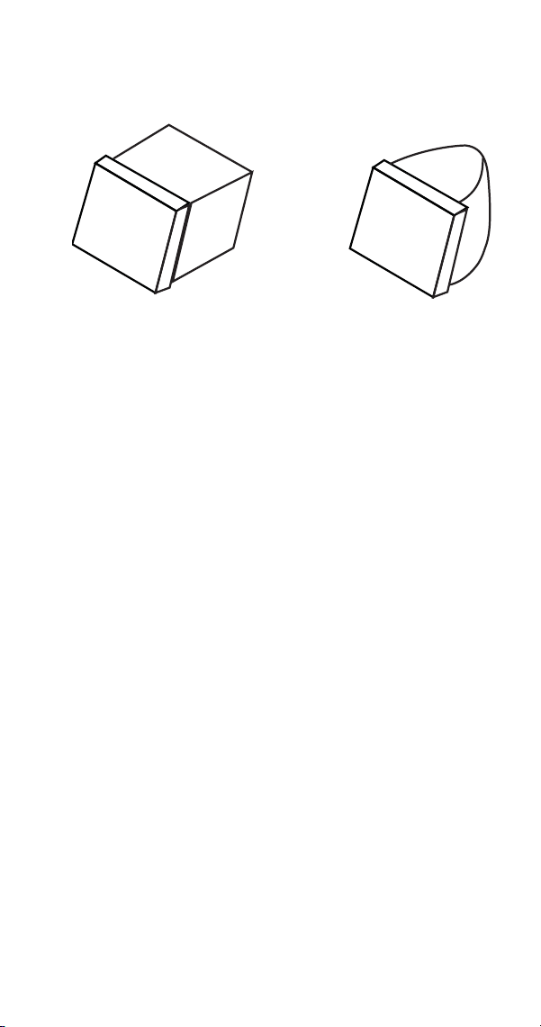
Part Number 8014793 6/18 115
Harvest Problems
Definition of a harvest problem; At the end of a 3.5
minute harvest cycle the slab of ice is still contacting
the evaporator. The slab of ice may or may not be
removable by hand.
Harvest problems can be split into two categorizes.
• Melted sheet of cubes at the end of the harvest
cycle. Ice can be removed rather easily by hand.
The back of the cubes are misshapen and melted.
This indicates something is on the evaporator
preventing the ice slab from releasing. Follow the
appropriate flow chart (in Troubleshooting) to
determine the cause of the problem. A manual
cleaning procedure must always be performed
when this problem is encountered.
• Normal sheet of cubes at the end of the harvest
cycle. Ice is difficult to remove from the evaporator
by hand. Once removed the back of the cubes are
square and show no signs of melting. This
indicates a refrigeration problem. The source of
the problem could be in the freeze or harvest
cycle. Use the appropriate flow chart (in
Troubleshooting) to determine the cause of the
problem.
Normal Ice Cube
Melted Out Ice Cube
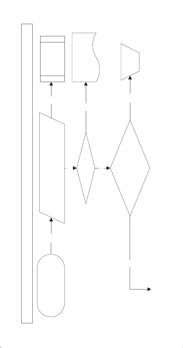
116 Part Number 8014793 6/18
SYMPTOM #3 ICE WILL NOT HARVEST, CUBES ARE NOT MELTED
YES
YES
YES
NO
NO
NO
YES
Ice Machine Will Not Harvest - Freeze Cycle is Normal and Ice Cubes are Not Melted After Harvest
Low production,
Normal fill pattern, long
harvest cycle, Possible SL #2,
Back of cubes are not melted
Discharge line temperature is normal
at the end of the freeze cycle?
S850/S1000 (A/W) = >140F/60C
All other S Models = >150F/65C
Refer to
Symptom #2
Freeze Cycle
Operational
Analysis Table
Is harvest valve energized?
Refer to Sequence of
Operation &
Wiring Diagrams
Is head pressure high &
suction pressure low
in harvest?
(Refer to Pressure Charts)
Replace
harvest
valve
Continued on Next Page...
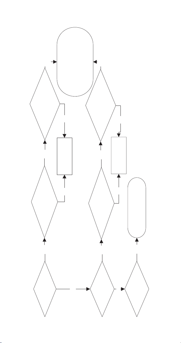
Part Number 8014793 6/18 117
YES
YES
YES
YES
YES
YES
YES
NO
NO
NO
NO
NO
NO
Self Contained
Air-cooled Condenser?
Self Contained
Water-cooled
Condenser?
Fan cycling
control operates correctly
in freeze cycle?
Fan cycling
control opens below setpoint
in harvest cycle?
Replace Fan
Cycling Control
Maintains correct
pressure in freeze cycle?
Stops water flow 100%
in harvest cycle?
Adjust or Replace
Water Regulating
Valve
Traditional Remote
Air-cooled Condenser?
Are you sure Discharge line
temperature is normal?
Repeat this flowchart
& verify all data
Refer to Symptom #3
Traditional Remotes Only Chart
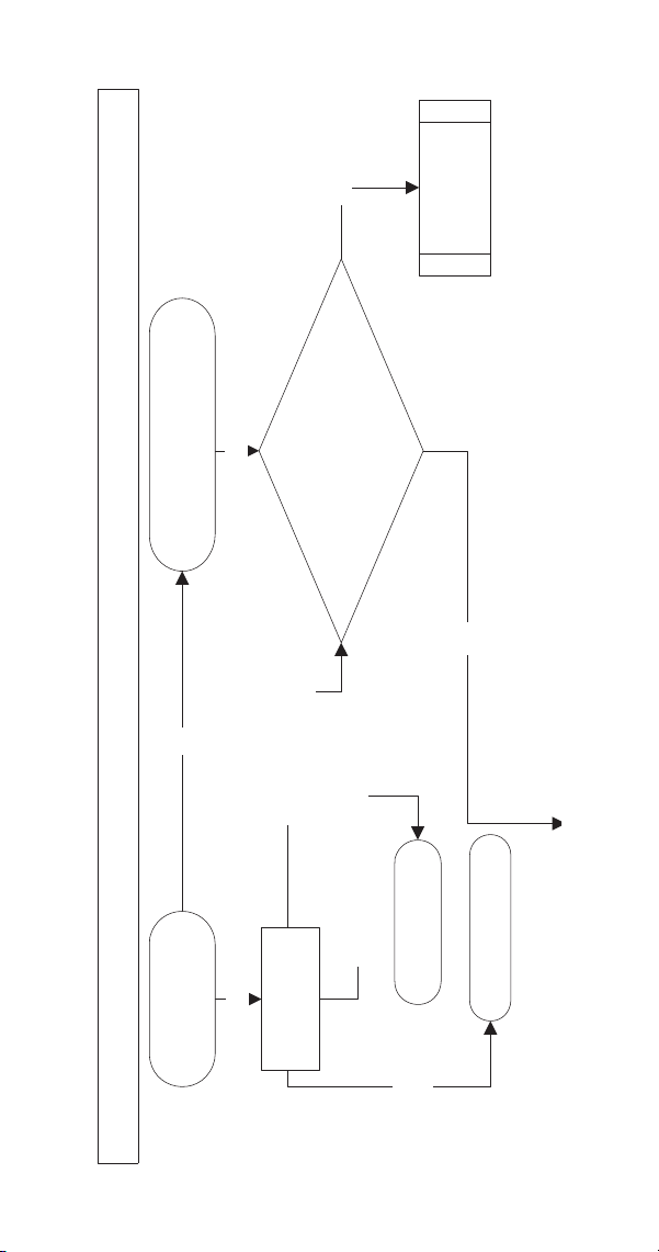
118 Part Number 8014793 6/18
SYMPTOM #3 - TRADITIONAL REMOTES ONLY
Refer to Symptom
#2 - Freeze Cycle
Analysis Chart
Traditional Remote Ice Machine - Long Harvest/Low Production/Intermittent Safety Limit 2
Fails at night or in low
ambient - Operates
normally above 70F/21C
YES
YES
YES
NO
Liquid Line Temperature Cool
NO
Liquid Line
Temperature Hot
Liquid Line
Temperature Warm
(body temperature)
Wet condenser
with water during
freeze cycle
Replace Headmaster
System low on refrigerant
Normal ice fill, long harvest cycle,
possible SL #2, back of cubes are
not melted at the end of harvest cycle
Discharge line temperature
is normal at the end of the
freeze cycle?
All S Model Remotes = >150F/65C
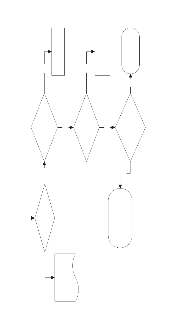
Part Number 8014793 6/18 119
Refer to Sequence of
Operation &
Wiring Diagrams
YES
YES
YES
NO
NO
NO
YES
NO
YES
Is harvest valve energized?
Is head pressure high &
suction pressure low
in harvest?
Replace Harvest Valve
Is head pressure low &
suction pressure low
in harvest?
Is head pressure normal &
suction pressure normal
in harvest?
Refer to Harvest Pressure
Regulating Valve
Diagnostics
Repeat this flowchart &
verify all data
Refer to Symptom #4 -
Will Not Harvest, Freeze
Cycle Normal & Ice Cubes are
Melted Flowchart
Single Evaporator Systems with Dual Harvest Valves: If one Harvest Vavle is open and the other is restricted / stuck closed you may have
normal harvest pressures. Look for ice not melting on one side of the evaporator.
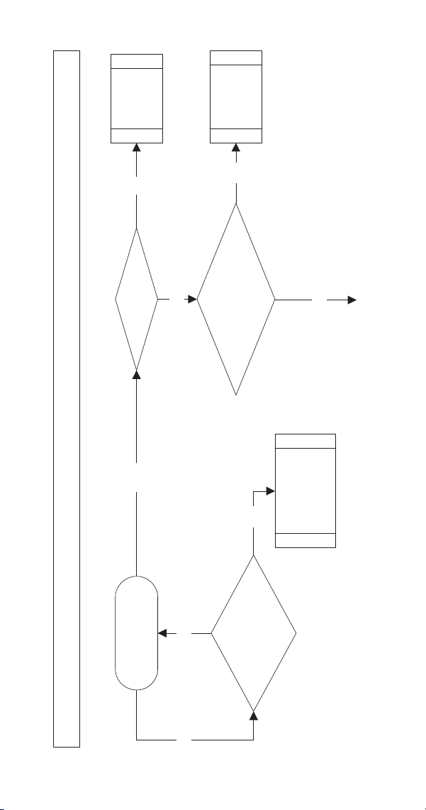
120 Part Number 8014793 6/18
SYMPTOM #4 WILL NOT HARVEST, MELTED CUBES
Level Ice
Machine
Refer to
Dump Valve
Diagnostics
Is water flowing over the
evaporator in the first 45 seconds
of harvest?
Is Ice
Machine level?
Are back of the cubes
melted at end of
harvest cycle?
Does ice remain frozen to
the evaporator at the end of
the harvest cycle?
YES
YES
YES
YES
NO
NO
NO
NO
Ice Machine Will Not Harvest - Freeze Cycle is Normal and Ice Cubes are Melted After Harvest
Continued on Next Page...
Refer to
Symptom #2
Freeze Cycle
Operational
Analysis Table
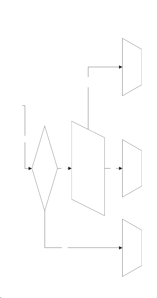
Part Number 8014793 6/18 121
Refer to Symptom #2
Freeze Cycle Operational
Analysis Table
Refer to Heavily Scaled
Cleaning Procedure
Discharge line temperature is normal
at the end of the freeze cycle?
S850/S1000 (A/W) = >140F/60C
All other S Models = >150F/65C
Refer to Manual
Cleaning Procedure
Is the evaporator dirty?
(Dry evaporator first then check)
YES
YES
NO
NO
NO

122 Part Number 8014793 6/18
This Page Intentionally Left Blank
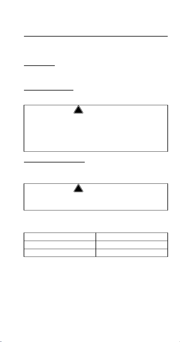
Part Number 8014793 6/18 123
Component Check Procedures
Electrical Components
MAIN FUSE
FUNCTION
The control board fuse stops ice machine operation if
electrical components fail, causing high amp draw.
SPECIFICATIONS
The main fuse is 250 Volt, 7 amp.
CHECK PROCEDURE
1. If the bin switch light is on with the water curtain/
ice dampers closed, the fuse is good.
2. Remove the fuse. Check for continuity across the
fuse with an ohmmeter.
!
Warning
High (line) voltage is applied to the control board
(terminals #55 and #56) at all times. Removing the
control board fuse or moving the toggle switch to
OFF will not remove the power supplied to the
control board.
!
Warning
Disconnect electrical power to the entire ice
machine before proceeding.
Reading Result
Open (OL) Replace fuse
Closed (O) Fuse is good
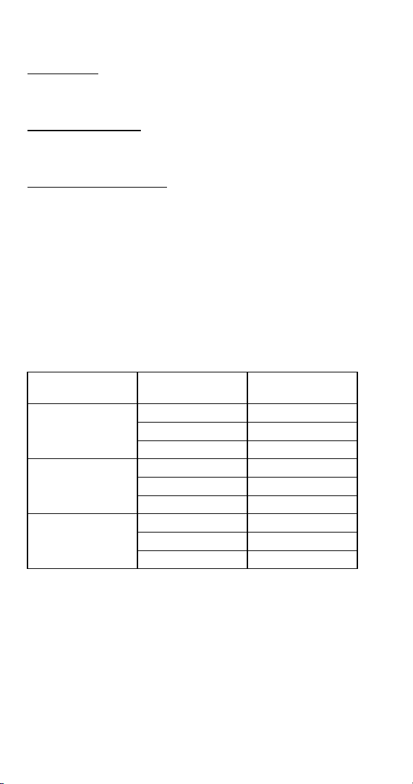
124 Part Number 8014793 6/18
ICE/OFF/CLEAN TOGGLE SWITCH
FUNCTION
The switch is used to place the ice machine in ICE,
OFF or CLEAN mode of operation.
SPECIFICATIONS
Single-pole, double-throw switch. The switch is
connected into a varying low D.C. voltage circuit.
CHECK PROCEDURE
NOTE: Because of a wide variation in D.C. voltage, it
is not recommended that a voltmeter be used to check
toggle switch operation.
1. Inspect the toggle switch for correct wiring.
2. Isolate the toggle switch by disconnecting the
Molex connector.
3. Check continuity across the toggle switch
terminals. Note where the wire numbers are
connected to the switch terminals, or refer to the
wiring diagram to take proper readings.
4. Replace the toggle switch if continuity readings do
not match all three switch settings.
Switch
Setting
Terminals Ohm Reading
ICE
1-6 Open
1-2 Closed
2-6 Open
CLEAN
1-6 Closed
1-2 Open
2-6 Open
OFF
1-6 Open
1-2 Open
2-6 Open

Part Number 8014793 6/18 125
BIN SWITCH
FUNCTION
Movement of the water curtain/ice dampers control bin
switch operation. The bin switch has two main
functions:
1. Terminating the Harvest cycle and returning the
ice machine to the Freeze cycle. This occurs
when the bin switch is opened and closed again
within 30 seconds during the Harvest cycle.
2. Automatic ice machine shut-off.
If the storage bin is full at the end of a Harvest
cycle, the sheet of cubes fails to clear the water
curtain/ice dampers and holds it open. After the
water curtain/ice dampers are held open for 30
seconds, the ice machine shuts off. The ice
machine remains off until enough ice is removed
from the storage bin to allow the sheet of cubes to
drop clear of the water curtain/ice dampers. As
the water curtain/ice dampers swing back to the
operating position, the bin switch closes and the
ice machine restarts, provide the 3-minute delay
has expired.
SPECIFICATIONS
The bin switch is a magnetically operated reed switch.
The magnet is attached to the lower right corner of the
water curtain/ice dampers. The switch is attached to
the right bulkhead wall.
The bin switch is connected to a varying D.C. voltage
circuit. (Voltage does not remain constant.)
NOTE: Because of a wide variation in D.C. voltage, it
is not recommended that a voltmeter be used to check
bin switch operation.
Important
The water curtain/ice dampers must be ON (bin
switch closed) to start ice making.

126 Part Number 8014793 6/18
SYMPTOMS
Bin Switch Fails Open
• The ice machine will not start with the toggle
switch in the ice position, but runs normally with
the toggle switch in the clean position.
Bin Switch Fails Closed
• Safety limit 2 is recorded in the control board
memory and the harvest cycle continues after the
ice opens and closes the water curtain/ice
dampers (harvest cycle is 3.5 minutes for single
evaporators and 7 minutes for Quad evaporator
models).
DIAGNOSTIC AIDS:
• Always use the water curtain/ice dampers magnet
to cycle the switch (a larger or smaller magnet will
affect switch operation).
• Readings are affected by your test lead connection
and VOM battery strength. Verify you have solid
connections and a correctly functioning VOM
before testing bin switch.
• Open the curtain/ice dampers for 3 seconds, then
close the curtain/ice dampers for 3 seconds. This
will allow your VOM display to settle.
• With the bin switch closed your meter reading
should be 0 (0 to 10 is acceptable). With the
curtain/ice dampers open the reading must be
infinity (OL).
CONTINUITY TEST
1. Disconnect the bin switch wires to isolate the bin
switch from the control board.
2. Connect an ohmmeter to the disconnected bin
switch wires.
3. Cycle the bin switch open and closed 25 times by
opening and closing the water curtain/ice
dampers. Watch for consistent readings each time
the bin switch is cycled open and closed (bin
switch failure could be erratic).

Part Number 8014793 6/18 127
Water Curtain/Ice Damper Removal Notes
The water curtain must be on (bin switch closed) to
start ice making. While a Freeze cycle is in progress,
the water curtain can be removed and installed at any
time without interfering with the electrical control
sequence.
If the ice machine goes into Harvest sequence while
the water curtain is removed, one of the following will
happen:
• Water curtain remains off:
When the Harvest cycle time reaches 3.5 minutes
and the bin switch is not closed, the ice machine
stops as though the bin were full.
• Water curtain is put back on:
If the bin switch closes prior to reaching the
3.5-minute point, the ice machine immediately
returns to another Freeze sequence prechill.

128 Part Number 8014793 6/18
CLEANING THE ICE THICKNESS OR WATER
LEVEL PROBE
Clean the probes using the following procedure.
1. Mix a solution of Manitowoc ice machine cleaner
and water (2 ounces of cleaner to 16 ounces of
water) in a container.
2. Soak probes in container of cleaner/water solution
while disassembling and cleaning water circuit
components (soak probes for 10 minutes or
longer).
3. Clean all probe surfaces including all plastic parts
(do not use abrasives). Verify all cavities are
clean. Thoroughly rinse probes (including cavity)
with clean water, then dry completely. Incomplete
rinsing and drying of the ice thickness probe
can cause premature harvest.
Reinstall probes, then sanitize all ice machine and bin/
dispenser interior surfaces.

Part Number 8014793 6/18 129
WATER LEVEL CONTROL CIRCUITRY
The water level probe circuit can be monitored by
watching the water level light. The water level light is
on when water contacts the probe, and off when no
water is in contact with the probe. The water level light
functions any time power is applied to the ice machine,
regardless of toggle switch position.
FREEZE CYCLE WATER LEVEL SETTING
During the Freeze cycle, the water level probe is set to
maintain the proper water level above the water pump
housing. The water level is not adjustable. If the water
level is incorrect, check the water level probe position.
Reposition or replace the probe as necessary.
WATER INLET VALVE SAFETY SHUT-OFF
In the event of a water level probe failure, this feature
limits the water inlet valve to a six-minute on time.
Regardless of the water level probe input, the control
board automatically shuts off the water inlet valve if it
remains on for 12 continuous minutes. This is
important to remember when performing diagnostic
procedures on the water level control circuitry.
FREEZE CYCLE CIRCUITRY
Manitowoc’s electronic sensing circuit does not rely on
float switches or timers to maintain consistent water
level control. During the Freeze cycle, the water inlet
valve energizes and de-energizes in conjunction with
the water level probe located in the water trough.
During the first 45 seconds of the Freeze cycle:
• The water inlet valve is ON when there is no water
in contact with the water level probe.
• The water inlet valve turns OFF after water
contacts the water level probe for 3 continuous
seconds.
• The water inlet valve will cycle ON and OFF as
many times as needed to fill the water trough.
After 45 seconds into the Freeze cycle:
The water inlet valve will cycle ON, and then OFF one
more time to refill the water trough. The water inlet
valve is now OFF for the duration of the freeze cycle.
4.

130 Part Number 8014793 6/18
Diagnosing Water Level Control Circuitry
PROBLEM: WATER TROUGH OVERFILLING
DURING THE FREEZE CYCLE
Step 1 Start a new Freeze sequence by moving the
ICE/OFF/CLEAN toggle switch to OFF and then back
to ICE.(if water flows with the switch off, check the
water inlet valve).
Step 2 Wait until the Freeze cycle starts (the Freeze
cycle starts when the water pump energizes).
Step 3 Disconnect the water level probe from the
control board, then connect a jumper from the control
board terminal and any cabinet ground, & refer to
chart on the next page
.
Important
This restart must be done prior to performing
diagnostic procedures. This assures the ice machine
is not in a Freeze cycle water inlet valve safety shut-
off mode. You must complete the entire diagnostic
procedure within 6 minutes of starting.
Important
For the test to work properly you must wait until the
Freeze cycle starts, prior to disconnecting the water
level probe. If you restart the test, you must
reconnect the water level probe, restart the ice
machine (step 1), and then disconnect the water
level probe after the compressor starts.

Part Number 8014793 6/18 131
WATER TROUGH OVERFILLING CONTINUED
Step 3. Jumper Wire Connected from
Control Board Terminal to Ground
Is Water
Flowing
into the
Water
Trough?
The
Water
Level
Light Is:
The Water
Inlet Valve
Solenoid
Coil Is:
Cause
No On De-energized
The water level
probe is
causing the
problem. Ohm,
then clean or
replace the
water level
probe.
Yes Off Energized
The control
board is
causing the
problem.
Yes On De-energized
The water fill
valve is
causing the
problem.

132 Part Number 8014793 6/18
PROBLEM: WATER WILL NOT RUN INTO THE
SUMP TROUGH DURING THE FREEZE CYCLE
Step 1 Verify water is supplied to the ice
machine.Start a new Freeze sequence by moving the
ICE/OFF/CLEAN toggle switch to OFF, then back to
ICE.
Step 2 Wait until the freeze cycle starts
(approximately 45 seconds, the freeze cycle starts
when the compressor energizes).
Important
This restart must be done prior to performing
diagnostic procedures. This assures the ice machine
is not in a freeze cycle water inlet valve safety shut-
off mode. You must complete the entire diagnostics
within 6 minutes of starting.

Part Number 8014793 6/18 133
Step 3 Disconnect the water level probe from the
water level probe terminal on the control board.
Important
For the test to work properly you must wait until the
Freeze cycle starts, prior to disconnecting the water
level probe. If you restart the test, you must
reconnect the water level probe, restart the ice
machine (step 1), and then disconnect the water
level probe after the compressor starts.
Step 3. Disconnect Probe from Control Board
Is Water
Flowing
into the
Water
Trough?
The
Water
Level
Light Is:
The Water
Inlet Valve
Solenoid
Coil Is:
Cause
Yes Off Energized
The water level
probe is
causing the
problem.
Clean or
replace the
water level
probe.
No Off Energized
The water inlet
valve is causing
the problem.
No On or Off De-energized
The control
board is
causing the
problem.

134 Part Number 8014793 6/18
ICE THICKNESS PROBE (HARVEST INITIATION)
HOW THE PROBE WORKS
Manitowoc’s electronic sensing circuit does not rely on
refrigerant pressure, evaporator temperature, water
levels or timers to produce consistent ice formation.
As ice forms on the evaporator, water (not ice)
contacts the ice thickness probe. After the water
completes this circuit across the probe continuously
for 6-10 seconds, a Harvest cycle is initiated.
ICE PROBE LIGHT
This light’s primary function is to be on as water
contacts the ice thickness probe during the freeze
cycle, and remain on throughout the entire harvest
cycle. The light will flicker as water splashes on the
probe.
FREEZE TIME LOCK-IN FEATURE
The ice machine control system incorporates a freeze
time lock-in feature. This prevents the ice machine
from short cycling in and out of harvest.
The control board locks the ice machine in the freeze
cycle for six minutes. If water contacts the ice
thickness probe during these six minutes, the ice
probe or harvest light will come on (to indicate that
water is in contact with the probe), but the ice machine
will stay in the freeze cycle. After the six minutes are
up, a harvest cycle is initiated. This is important to
remember when performing diagnostic procedures on
the ice thickness control circuitry.
To allow the service technician to initiate a harvest
cycle without delay, this feature is not used on the first
cycle after moving the toggle switch OFF and back to
ICE.
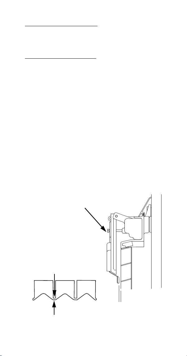
Part Number 8014793 6/18 135
MAXIMUM FREEZE TIME
The control system includes a built-in safety which will
automatically cycle the ice machine into harvest after
60 minutes in the freeze cycle.
ICE THICKNESS CHECK
The ice thickness probe is factory-set to maintain the
ice bridge thickness at 1/8 in. (32 mm).
NOTE: Make sure the water curtain/splash shields
are in place when performing this check. It prevents
water from splashing out of the water trough.
1. Inspect the bridge connecting the cubes. It should
be about 1/8 in. (32 mm) thick.
2. If adjustment is necessary, turn the ice thickness
probe adjustment screw clockwise to increase
bridge thickness or counterclockwise to decrease
bridge thickness. Set a 1/4” gap between the ice
thickness probe and evaporator as a starting
point. Then adjust to achieve 1/8” ice thickness.
NOTE: The starting point before final adjustment is
approximately a 1/4 in. gap.
Make sure the ice thickness probe wire and the
bracket do not restrict movement of the probe
ADJUSTING
SCREW
SV3132
ICE THICKNESS ADJUSTMENT
1/8” ICE BRIDGE THICKNESS

136 Part Number 8014793 6/18
Diagnosing Ice Thickness Control Circuitry
PROBLEM: ICE MACHINE DOES NOT CYCLE INTO
HARVEST WHEN WATER CONTACTS THE ICE
THICKNESS CONTROL PROBE
Step 1 Bypass the freeze time lock-in feature by
moving the ICE/OFF/CLEAN switch to OFF and back
to ICE.
Step 2 Wait until water starts to flow over the
evaporator (freeze cycle).
Step 3 Disconnect the ice thickness control from the
control board, then connect a jumper wire from the
control board to any cabinet ground and monitor the
ice probe light.
Ice Probe Light On
• The ice probe light comes on, and 10 seconds
later, the ice machine cycles from Freeze to
Harvest.
• The ice thickness probe is causing the
malfunction.
• The ice probe light comes on, but the ice machine
stays in the Freeze sequence.
The control board is causing the malfunction.
Ice Probe Light Off
• The ice probe light does not come on.
The control board is causing the malfunction.
If you suspect a defective probe check for continuity
from the ice thickness probe to the connector.
• With continuity DO NOT change the probe.
• Without continuity, the probe is defective.

Part Number 8014793 6/18 137
PROBLEM: ICE MACHINE CYCLES INTO HARVEST
BEFORE WATER CONTACT WITH THE ICE
THICKNESS PROBE
Step 1 Bypass the freeze time lock-in feature by
moving the ICE/OFF/CLEAN switch to OFF and back
to ICE.
Step 2 Disconnect the ice thickness probe from the
control board.
Step 3 Wait until water starts to flow over the
evaporator, then monitor the ice probe light:
Ice Probe Light Off
• The ice probe light stays off, and the ice machine
remains in the Freeze sequence.
The ice thickness probe is causing the malfunction.
Verify that the ice thickness probe is adjusted correctly
and clean.
Ice Probe Light On
• The ice probe light comes on, and 10 seconds
later, the ice machine cycles from Freeze to
Harvest.
The control board is causing the malfunction.
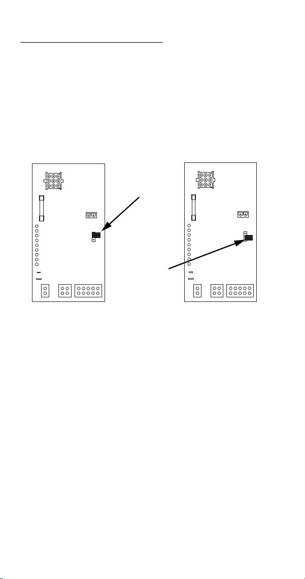
138 Part Number 8014793 6/18
HARVEST CYCLE CIRCUITRY
The water level probe does not control the water inlet
valve during the harvest cycle. During the harvest
cycle water purge, the water inlet valve energizes and
de-energizes strictly by time. The harvest water purge
may be set at 45 seconds (top and center terminals) or
0 seconds (center and bottom terminals). Set the
harvest water purge to 0 seconds when reverse
osmosis or deionized water is used. Use the factory
setting of 45 seconds for all other types of water.
0 Second
Jumper
Position
45 Second
Jumper
Position

Part Number 8014793 6/18 139
HARVEST ASSIST AIR PUMP
FUNCTION
The air pump breaks the vacuum between the sheet of
ice and the evaporator which results in shorter harvest
cycles.
SPECIFICATIONS
115 Volt or 230 Volt - matches the ice machine
voltage.
CHECK PROCEDURE
1. Verify when the air pump should be running in the
sequence of operation.
2. If the compressor is not running when it should be
check voltage at the control board.
3. If there is no voltage present at the control board,
replace the control board.
4. If there is voltage present at the control board
check for voltage at the air pump connector.
5. If there is no voltage present at the air pump
connector replace wire.
6. If there is voltage at the air pump connector, use a
volt ohm meter to verify there is no continuity
through the motor windings then replace motor.

140 Part Number 8014793 6/18
Compressor Electrical Diagnostics
The compressor does not start or will trip repeatedly
on overload.
Check Resistance (Ohm) Values
NOTE: Compressor windings can have very low ohm
values. Use a properly calibrated meter.
Perform the resistance test after the compressor
cools. The compressor dome should be cool enough
to touch (below 120°F/49°C) to assure that the
overload is closed and the resistance readings will be
accurate.
SINGLE PHASE COMPRESSORS
1. Disconnect power then remove the wires from the
compressor terminals.
2. The resistance values between C and S and
between C and R, when added together, should
equal the resistance value between S and R.
3. If the overload is open, there will be a resistance
reading between S and R, and open readings
between C and S and between C and R. Allow the
compressor to cool, then check the readings
again.
THREE PHASE COMPRESSORS
1. Disconnect power and remove the wires from the
compressor terminals.
2. The resistance values between L1 and L2,
between L2 and L3, and between L3 and L1
should all be equal.
3. If the overload is open, there will be open
readings between L1 and L2, between L2 and L3,
and between L3 and L1. Allow the compressor to
cool, then check the readings again.

Part Number 8014793 6/18 141
CHECK MOTOR WINDINGS TO GROUND
Check continuity between all three terminals and the
compressor shell or copper refrigeration line. Scrape
metal surface to get good contact. If continuity is
present, the compressor windings are grounded and
the compressor should be replaced.
COMPRESSOR DRAWING LOCKED ROTOR
To determine if the compressor is seized, check the
amp draw while the compressor is trying to start.
The two likely causes of this are a defective starting
component and a mechanically seized compressor.
To determine which you have:
1. Install high and low side gauges.
2. Try to start the compressor.
3. Watch the pressures closely.
A. If the pressures do not move, the compressor
is seized. Replace the compressor.
B. If the pressures move, the compressor is
turning slowly and is not seized. Check the
capacitors and relay.
COMPRESSOR DRAWING HIGH AMPS
The continuous amperage draw on start-up should not
be near the maximum fuse size indicated on the serial
tag.

142 Part Number 8014793 6/18
DIAGNOSING START COMPONENTS
If the compressor attempts to start, or hums and trips
the overload protector, check the start components
before replacing the compressor.
Capacitor
Visual evidence of capacitor failure can include a
bulged terminal end or a ruptured membrane. Do not
assume a capacitor is good if no visual evidence is
present. A good test is to install a known good
substitute capacitor. Use a capacitor tester when
checking a suspect capacitor. Clip the bleed resistor
off the capacitor terminals before testing.
• If the compressor attempts to start, or hums and
trips the overload protector, check the starting
components before replacing the compressor.
• Visual evidence of capacitor failure can include a
bulged terminal end or a ruptured membrane. Do
not assume a capacitor is good if no visual
evidence is present.
• A good test is to install a known good substitute
capacitor.
• Use a capacitor tester when checking a suspect
capacitor. Clip the bleed resistor off the capacitor
terminals before testing.

Part Number 8014793 6/18 143
Relay
The relay has a set of contacts that connect and
disconnect the start capacitor from the compressor
start winding. The contacts on the relay are normally
closed (start capacitor in series with the start winding).
The relay senses the voltage generated by the start
winding and opens the contacts as the compressor
motor starts. The contacts remain open until the
compressor is de-energized.
RELAY OPERATION CHECK
1. Disconnect wires from relay terminals.
2. Verify the contacts are closed.
Measure the resistance between terminals 1 and
2. No continuity indicates open contacts. Replace
the relay.
3. Check the relay coil.
Measure the resistance between terminals 2 and
5. No resistance indicates an open coil. Replace
the relay.

144 Part Number 8014793 6/18
PTCR
The PTCR allows current to flow through the start
winding at compressor startup. Current flow heats the
ceramic discs in the PTCR. The electrical resistance
increases with temperature and stops all except a
trickle of current flow through the start winding. The
small flow of current keeps the PTCR hot (260°F/
127°C) and the start winding out of the circuit.
The PTCR must be cooled before attempting to start
the compressor, otherwise the PTCR will heat up too
quickly and stop current flow through the start winding
before the compressor motor reaches full speed..
NOTE: If a PTCR is dropped internal damage can
occur to the ceramic PTCR discs. The ceramic disc
can chip and cause arcing which leads to PTCR
failure. Since there is no way to open the PTCR in
order to determine if the ceramic disc is chipped or
not, it must be discarded when dropped.
!
Warning
Disconnect electrical power to the entire ice
machine at the building electrical disconnect box
before proceeding.
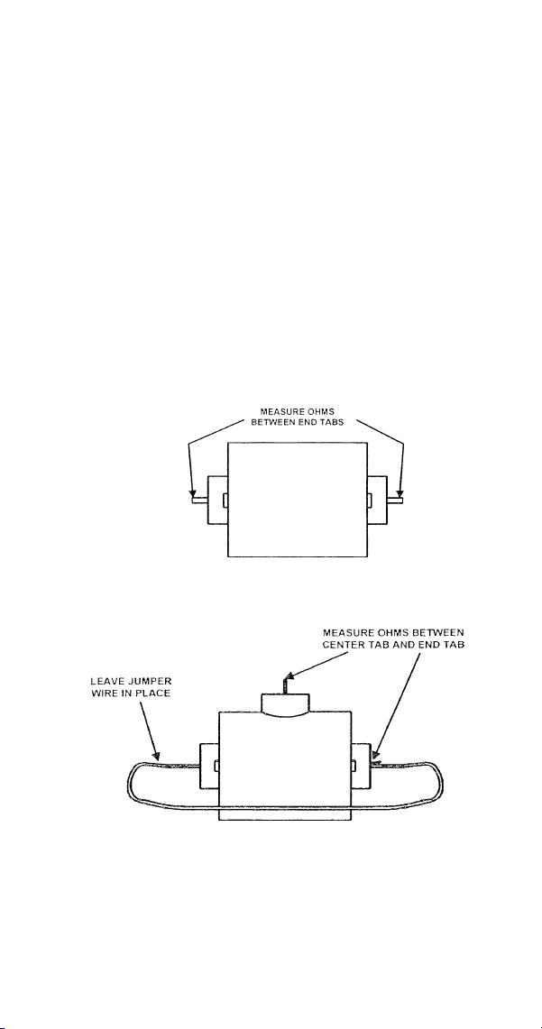
Part Number 8014793 6/18 145
PTCR Operation Check
1. Visually inspect the PTCR. Check for signs of
physical damage.
NOTE: The PTCR case temperature may reach
210°F (100°C) while the compressor is running. This is
normal. Do not change a PTCR just because it is hot.
2. Wait at least 10 minutes for the PTCR to cool to
room temperature.
3. Remove the PTCR from the ice machine.
4. Measure the resistance of the PTCR as shown.
The resistance reading must be between:
• S600/S850/S1000 =18 to 40 ohms
• S1200/S1400/S1600/S1800 =
8 to 22 ohms.
S1200/S1400/S1600/S1800
S600/S850/S1000

146 Part Number 8014793 6/18
Refrigeration Components
HIGH PRESSURE CUTOUT (HPCO) CONTROL
FUNCTION
Stops the ice machine if subjected to excessive high-
side pressure. The HPCO control is normally closed,
and opens on a rise in discharge pressure.
CHECK PROCEDURE
1. Set ICE/OFF/CLEAN switch to OFF, (Manual
reset HPCO reset if tripped).
2. Connect manifold gauge set.
3. Hook voltmeter in parallel across the HPCO,
leaving wires attached.
4. On water-cooled models, close the water service
valve to the water condenser inlet. On self-
contained air-cooled and remote models,
disconnect the fan motor.
Specifications
Cut-Out Cut-In
450 psig ±10
(3103 kPa ±69 31 bar ±.69)
Automatic Reset
(Must be below 300 psig (2068 kPa 20.68 bar) to reset.)
ST3000 R410A Refrigerant Only
600 psig ±10
(3147 kPa ±69)
450 psig ±10
(3103 kPa ±69)

Part Number 8014793 6/18 147
5. Set ICE/OFF/CLEAN switch to ICE.
6. No water or air flowing through the condenser will
cause the HPCO control to open because of
excessive pressure. Watch the pressure gauge
and record the cut-out pressure.
Replace the HPCO control if it:
7. Will not reset [below 300 psig (2068 kPa 20.68
bar).
8. Does not open at the specified cut-out point.
!
Warning
If discharge pressure exceeds cutout setting and the
HPCO control does not cut out, set ICE/OFF/CLEAN
switch to OFF to stop ice machine operation.
148 Part Number 8014793 6/18
FAN CYCLE CONTROL
Self-Contained Air-Cooled Models Only
FUNCTION
Cycles the fan motor on and off to maintain proper
operating discharge pressure.
The fan cycle control closes on an increase, and
opens on a decrease in discharge pressure.
CHECK PROCEDURE
1. Verify fan motor windings are not open or
grounded, and fan spins freely.
2. Connect manifold gauges to ice machine.
3. Hook voltmeter in parallel across the fan cycle
control, leaving wires attached.
4. Refer to chart below.
Specifications
Model Cut-In (Close) Cut-Out (Open)
S300 / S320
S420 / S450
S500 / S600
S850
250 ±5
(1723 kPa ±.34)
(17.23 bar ±.34)
200 ±5
(1517 kPa ±.34)
(15.17 bar ±.34)
S1000 / S1200
S1400 / S1600
S1800
275 psig ±5
(1896 kPa ±34)
(18.96 bar±.34)
225 psig ±5
(1551 kPa ±34)
(15.51 bar ±.34)
FCC Setpoint:
Reading Should
Be:
Fan
Should Be:
Above Cut-In 0 Volts Running
Below Cut-Out Line Voltage Off

Part Number 8014793 6/18 149
WATER REGULATING VALVE
Self-Contained Water-Cooled Models Only
FUNCTION
The water regulating valve maintains the freeze cycle
discharge pressure.
• The valve setting for the ST3000W is 230 psig.
• The valve setting for the S3300W-HP is 240 psig.
CHECK PROCEDURE
1. Determine if the head pressure is high or low
(refer to Operational Pressure Charts page 179).
2. Verify the condenser water meets specifications.
3. Adjust valve to increase or decrease discharge
pressure.
4. Determine the temperature of the liquid line
entering the receiver by feeling it. This line is
normally warm; body temperature.
5. Using the information gathered, refer to the list for
diagnosis.
Problem (Freeze Cycle)
Valve not maintaining discharge pressure.
• Valve incorrectly set, dirty or defective. Adjust,
clean or replace valve.
Discharge pressure extremely high; Liquid line
entering receiver feels hot.
• Water regulating valve incorrectly set or not
opening.
Discharge pressure low, Liquid line entering
receiver feels warm to hot.
• Ice machine low on charge. Verify Total System
Refrigerant Charge page 177.
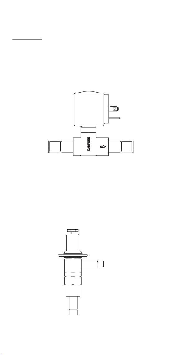
150 Part Number 8014793 6/18
HARVEST PRESSURE REGULATING (HPR)
SYSTEM REMOTES ONLY
GENERAL
The harvest pressure regulating (H.P.R.) system
includes:
• Harvest pressure regulating solenoid valve (H.P.R.
solenoid). This is an electrically operated valve
which opens when energized, and closes when
de-energized.
• Harvest pressure regulating valve (H.P.R. valve).
This is a pressure regulating valve which
modulates open and closed, based on the
refrigerant pressure at the outlet of the valve. The
valve closes completely and stops refrigerant flow
when the pressure at the outlet rises above the
valve setting.
INLET
OUTLET
FLOW
HPR SOLENOID
SV3053
OUTLET
INLET
HPR VALVE

Part Number 8014793 6/18 151
FREEZE CYCLE
The H.P.R. system is not used during the freeze cycle.
The H.P.R. solenoid is closed (de-energized),
preventing refrigerant flow into the H.P.R. valve.
HARVEST CYCLE
During the harvest cycle, the check valve in the
discharge line prevents refrigerant in the remote
condenser and receiver from back feeding into the
evaporator and condensing to liquid.
The H.P.R. solenoid is opened (energized) during the
harvest cycle, allowing refrigerant gas from the top of
the receiver to flow into the H.P.R. valve. The H.P.R.
valve modulates open and closed, raising the suction
pressure high enough to sustain heat for the harvest
cycle, without allowing refrigerant to condense to liquid
in the evaporator.
In general, harvest cycle suction pressure rises, then
stabilizes in the range of 70-100 psig (517-758 kPa).
Exact pressures vary from model to model. Refer to
the “Operational Refrigerant Pressures” charts
page 179.
HPR DIAGNOSTICS
Steps 1 through 4 can be quickly verified without
attaching a manifold gauge set or thermometer.
All questions must have a yes answer to continue
the diagnostic procedure.
1. Liquid line warm?
(Body temperature is normal)
If liquid line is cooler than body temperature, refer
to head pressure control valve diagnostics
page 153.
2. Ice fill pattern normal?
Refer to “Ice Formation Pattern” if ice fill is not
normal page 99.

152 Part Number 8014793 6/18
3. Freeze time normal?
(Refer to Cycle Times/Refrigerant Pressures/24
Hour Ice Production Charts page 179)
Shorter freeze cycles - Refer to head pressure
control valve diagnostics page 153.
Longer freeze cycles - Refer to water system
checklist page 98, then refer to Refrigeration
Diagnostic Procedures .
4. Harvest time is longer than normal and control
board indicates safety limit #2?
(Refer to Cycle Times/Refrigerant Pressures/24
Hour Ice Production Charts page 179)
Connect refrigeration manifold gauge set to the
access valves on the front of the ice machine.
Establish baseline by recording suction and
discharge pressure and freeze & harvest cycle
times. (Refer to “Freeze Cycle Refrigeration
System Operational Analysis Tables” for data
collection detail page 80).
5. Discharge line temperature is greater than 150°F
(66°C) [S850/S1000 Air/Water Only -
140°F (60°C)] at the end of the freeze cycle? (See
Discharge Line Temperature Analysis on
page 111)
6. Freeze cycle Head Pressure 220 psig
(1517 kPa 15.17 bar) or higher?
If the head pressure is lower than 220 psig
(1517 kPa 15.17 bar) refer to head pressure
control valve diagnostics page 153.
7. Freeze cycle Suction Pressure normal?
Refer to analyzing suction pressure if suction
pressure is high or low page 104.
8. Harvest cycle suction and discharge pressures
are lower than indicated in the cycle times/
refrigerant pressures/24 hour ice production
chart?
Replace Harvest Pressure Regulating solenoid.

Part Number 8014793 6/18 153
HEAD PRESSURE CONTROL VALVE
Manitowoc remote systems require head pressure
control valves with special settings. Replace defective
head pressure control valves only with “original”
Manitowoc replacement parts.
OPERATION
The R404A head pressure control valve is non
adjustable.
At ambient temperatures of approximately 70°F (21°C)
or above, refrigerant flows through the valve from the
condenser to the receiver inlet. At temperatures below
this (or at higher temperatures if it is raining), the head
pressure control dome’s nitrogen charge closes the
condenser port and opens the bypass port from the
compressor discharge line.
In this modulating mode, the valve maintains minimum
head pressure by building up liquid in the condenser
and bypassing discharge gas directly to the receiver.
DIAGNOSING
1. Determine if the coil is clean. Air passes through
the condenser from the bottom up. Verify the coil
is clean by looking from the bottom up. Do not
look down through the fan.
2. Determine the air temperature entering the
remote condenser.
3. Determine if the head pressure is high or low in
relationship to the outside temperature. (Refer to
the proper “Cycle Times/24-Hour Ice Production/
Refrigerant Pressure Charts” page 179).
4. Determine the temperature of the liquid line
entering the receiver by feeling it. This line is
normally warm; “body temperature.”

154 Part Number 8014793 6/18
5. Using the information gathered, refer to the chart
below.
NOTE: A head pressure control valve that will not
bypass, will function properly with condenser air
temperatures of approximately 70°F (21°C) or above.
When the temperature drops below 70°F (21°C), the
head pressure control valve fails to bypass and the ice
machine malfunctions. Lower ambient conditions can
be simulated by rinsing the condenser with cool water
during the freeze cycle.
Condition
Probable
Cause
Corrective
Measure
Discharge Pressure - High
Liquid Line Temperature -
Hot
Valve stuck in
bypass
Replace
valve
Discharge Pressure - Low
Liquid Line Temperature -
Cold
Valve not
bypassing
Replace
valve
Discharge Pressure - Low
Liquid Line Temperature -
Hot
Ice Machine
Low on
Charge
Low on
Charge
Verification

Part Number 8014793 6/18 155
FAN CYCLE CONTROL VS. HEAD PRESSURE
CONTROL VALVE
A fan cycle control cannot be used in place of a head
pressure control valve. The fan cycle control is not
capable of bypassing the condenser coil and keeping
the liquid line temperature and pressure up.
This is very apparent when it rains or the outside
temperature drops. When it rains or the outside
temperature drops, the fan begins to cycle on and off.
At first, everything appears normal. But, as it continues
raining or getting colder, the fan cycle control can only
turn the fan off. All the refrigerant must continue to flow
through the condenser coil, being cooled by the rain or
low outside temperature.
This causes excessive sub-cooling of the refrigerant.
As a result, the liquid line temperature and pressure
are not maintained for proper operation.

156 Part Number 8014793 6/18
LOW PRESSURE CUTOUT (LPCO) CONTROL
(ST3000/S3300 Only)
FUNCTION
Signals the control board to energize and de-energize
the ice machine when suction pressure rises above or
falls below setpoint.
The LPCO control is closed at pressures above
setpoint and opens at pressures below setpoint.
Two controls have been used and either will function
correctly.
CHECK PROCEDURE
1. Connect manifold gauge set at suction and
discharge access valves and verify refrigerant
pressure exceeds LPCO cut-in.
2. Isolate LPCO electrical leads, connect a
multimeter and read resistance.
Open = Replace Switch
Closed = Switch OK
NOTE: When the LPCO opens the compressor
contactor opens and the control board light will flash
When the control closes the compressor contactor
closes and the control board light stops flashing.
Specifications
Cut-Out Cut-In
12 psig ±3 35 psig ±3
7 psig ±3 22 psig ±3

Part Number 8014793 6/18 157
HARVEST PRESSURE SOLENOID VALVE
(ST3000/S3300 Only)
FUNCTION
Transfers refrigerant from the high side to the low side
during the harvest cycle.
CHECK PROCEDURE
1. Reset the ice machine with the toggle switch to
over ride the 6 minute freeze lock.
2. Initiate a premature harvest by grounding the ice
thickness probe.
3. Verify the coil has line voltage supplied in the
harvest cycle and magnetism is present
4. If voltage and magnetism are present Refer to S
Model Quad evaporator operational analysis chart
page 88.

158 Part Number 8014793 6/18
Refrigerant Recovery/Evacuation
NORMAL SELF-CONTAINED MODEL
PROCEDURES
Do not purge refrigerant to the atmosphere. Capture
refrigerant using recovery equipment. Follow the
manufacturer’s recommendations.
Connections
Manifold gauge sets must utilize low loss fittings to
comply with U.S. Government rules and regulations.
Make these connections:
• Suction side of the compressor through the suction
service valve.
• Discharge side of the compressor through the
discharge service valve.
Important
Manitowoc assumes no responsibility for the use of
contaminated refrigerant. Damage resulting from the
use of contaminated refrigerant is the sole
responsibility of the servicing company.
Important
Replace the liquid line drier before evacuating and
recharging. Use only a Manitowoc (OEM) liquid line
filter-drier to prevent voiding the warranty.
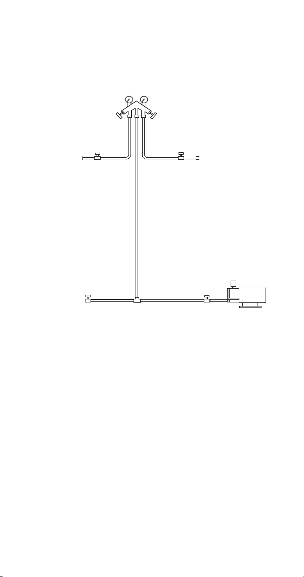
Part Number 8014793 6/18 159
Self-Contained Recovery/Evacuation
1. Place the toggle switch in the OFF position.
2. Install manifold gauge set, scale and recovery unit
or two-stage vacuum pump.
3. Open (backseat) the high and low side ice
machine service valves if required, and open high
and low side on manifold gauge set.
4. Perform recovery or evacuation:
A. Recovery: Operate the recovery unit as
directed by the manufacturer’s instructions.
B. Evacuation prior to recharging: Pull the
system down to 500 microns. Then, allow the
pump to run for an additional half hour. Turn
off the pump and perform a standing vacuum
leak check.
5. Follow the Charging Procedures.
MANIFOLD SET
OPEN
BACKSEATED
VACUUM PUMP/
RECOVERY UNIT
CLOSED
OPEN
LOW SIDE
SERVICE
VALVE
HIGH SIDE
SERVICE
VALVE
BACKSEATED
OPEN
RECOVERY/EVACUATION
CONNECTIONS
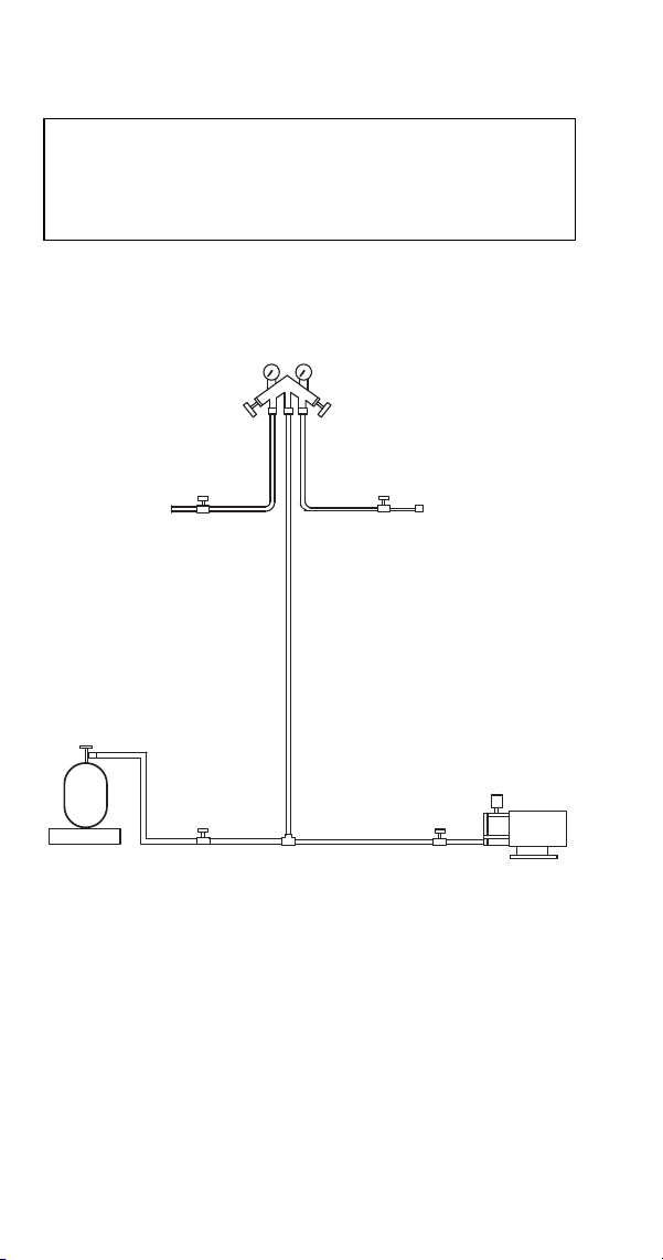
160 Part Number 8014793 6/18
Self-Contained Charging Procedures
1. Be sure the toggle switch is in the OFF position.
Important
The charge is critical on all Manitowoc ice
machines. Use a scale to ensure the proper
charge is installed.
MANIFOLD SET
CLOSED
FRONTSEATED
SCALE
VACUUM PUMP/
RECOVERY UNIT
OPEN
CLOSED
LOW SIDE
SERVICE
VALVE
HIGH SIDE
SERVICE
VALVE
BACKSEATED
OPEN
REFRIGERANT
CYLINDER
CHARGING CONNECTIONS

Part Number 8014793 6/18 161
2. Close the vacuum pump valve, the low side
service valve, and the low side manifold gauge
valve.
3. Open the high side manifold gauge valve, and
backseat the high side service valve.
4. Open the charging cylinder and add the proper
refrigerant charge (shown on nameplate) through
the discharge service valve.
5. Let the system “settle” for 2 to 3 minutes.
6. Place the toggle switch in the ICE position.
7. Close the high side on the manifold gauge set.
Add any remaining vapor charge through the
suction service valve (if necessary).
NOTE: Manifold gauge set must be removed properly
to ensure that no refrigerant contamination or loss
occurs.
8. Make sure that all of the vapor in the charging
hoses is drawn into the ice machine before
disconnecting the charging hoses.
A. Run the ice machine in freeze cycle.
B. Close the high side service valve at the ice
machine.
C. Open the low side service valve at the ice
machine.
D. Open the high and low side valves on the
manifold gauge set. Any refrigerant in the
lines will be pulled into the low side of the
system.
E. Allow the pressures to equalize while the ice
machine is in the freeze cycle.
F. Close the low side service valve at the ice
machine.
G. Remove the hoses from the ice machine and
install the caps.

162 Part Number 8014793 6/18
NORMAL REMOTE MODEL PROCEDURES
Refrigerant Recovery/Evacuation
Do not purge refrigerant to the atmosphere. Capture
refrigerant using recovery equipment. Follow the
manufacturer’s recommendations.
CONNECTIONS
Make these connections:
• Suction side of the compressor through the suction
service valve.
• Discharge side of the compressor through the
discharge service valve.
• Receiver outlet service valve, which evacuates the
area between the check valve in the liquid line and
the pump down solenoid.
• Access (Schrader) valve on the discharge line
quick-connect fitting, located on the outside of the
compressor/evaporator compartment. This
connection evacuates the condenser. Without it,
the magnetic check valves would close when the
pressure drops during evacuation, preventing
complete evacuation of the condenser.
Important
Manitowoc Ice assumes no responsibility for the
use of contaminated refrigerant. Damage
resulting from the use of contaminated refrigerant
is the sole responsibility of the servicing
company.
Important
Replace the liquid line drier before evacuating
and recharging. Use only a Manitowoc (O.E.M.)
liquid line filter drier to prevent voiding the
warranty.
Important
Recovery/evacuation of a remote system
requires connections at four points for complete
system evacuation.

Part Number 8014793 6/18 163
NOTE: Manitowoc recommends using an access
valve core removal and installation tool on the
discharge line quick-connect fitting. This permits
access valve core removal. This allows for faster
evacuation and charging, without removing the
manifold gauge hose.
REMOTE RECOVERY/EVACUATION
1. Place the toggle switch in the OFF position.
2. Install manifold gauge set, scale and recovery unit
or two-stage vacuum pump.
3. Open (backseat) the high and low side ice
machine service valves.
4. Open the receiver service valve halfway.
5. Open high and low side on the manifold gauge
set.
6. Perform recovery or evacuation:
A. Recovery: Operate the recovery unit as
directed by the manufacturer’s instructions.
B. Evacuation prior to recharging: Pull the
system down to 500 microns. Then, allow the
pump to run for an additional hour. Turn off
the pump and perform a standing vacuum
leak check.
NOTE: Check for leaks using a halide or electronic
leak detector after charging the ice machine.
7. Follow the Charging Procedures.
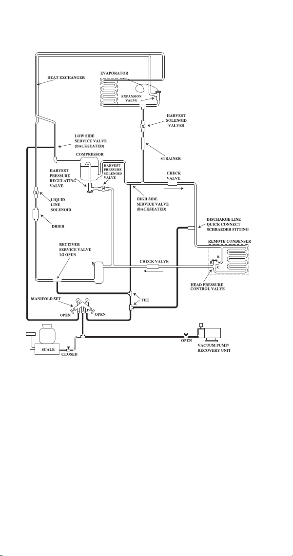
164 Part Number 8014793 6/18
REMOTE
RECOVERY/EVACUATION
CONNECTIONS

Part Number 8014793 6/18 165
Remote Charging Procedures
1. Be sure the toggle switch is in the OFF position.
2. Close the vacuum pump valve, the low and high
side service valves (front seat), and the low side
manifold gauge valve.
3. Open the refrigerant cylinder and add the proper
refrigerant charge (shown on nameplate) into the
system high side (receiver outlet valve and
discharge lines quick-connect fitting).
4. If the high side does not take the entire charge,
close the high side on the manifold gauge set,
and backseat (open) the low side service valve
and receiver outlet service valve. Start the ice
machine and add the remaining charge through
the low side (in vapor form) until the machine is
fully charged.
5. Ensure all vapor in charging hoses is drawn into
the machine, then disconnect the manifold gauge
set.
NOTE: Backseat the receiver outlet service valve
after charging is complete and before operating the ice
machine. If the access valve core removal and
installation tool is used on the discharge quick-connect
fitting, reinstall the Schrader valve core before
disconnecting the access tool and hose.
6. Run the ice machine in freeze cycle.
7. Close the high side service valve at the ice
machine.
8. Open the low side service valve at the ice
machine.
9. Open the high and low side valves on the
manifold gauge set. Any refrigerant in the lines
will be pulled into the low side of the system.
10. Allow the pressures to equalize while the ice
machine is in the freeze cycle.
11. Close the low side service valve at the ice
machine.
12. Remove the hoses from the ice machine and
install the caps.
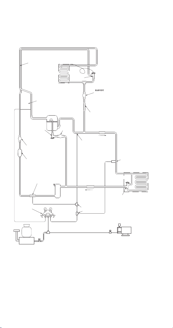
166 Part Number 8014793 6/18
x
x
x
SCHRAEDER FITTING
QUICK CONNECT
DISCHARGE LINE
CONTROL VALVE
HEAD PRESSURE
REMOTE CONDENSER
CLOSED
CLOSED
SCALE
RECOVERY UNIT
VACUUM PUMP/
SERVICE VALVE
1/2 OPEN
RECEIVER
MANIFOLD SET
OPEN
DRIER
SOLENOID
LINE
VALVE
REGULATING
PRESSURE
HARVEST
LIQUID
(BACKSEATED)
SERVICE VALVE
CHECK VALVE
TEE
OPEN
C
B
R
HIGH SIDE
(BACKSEATED)
SERVICE VALVE
LOW SIDE
COMPRESSOR
HARVEST
PRESSURE
SOLENOID
VALVE
VALVE
EXPANSION
VALVE
CHECK
STRAINER
VALVES
SOLENOID
HEAT EXCHANGER
EVAPORATOR
REMOTE CHARGING
CONNECTIONS

Part Number 8014793 6/18 167
System Contamination Clean-Up
General
This section describes the basic requirements for
restoring contaminated systems to reliable service.
DETERMINING SEVERITY OF CONTAMINATION
System contamination is generally caused by either
moisture or residue from compressor burnout entering
the refrigeration system.
Inspection of the refrigerant usually provides the first
indication of system contamination. Obvious moisture
or an acrid odor in the refrigerant indicates
contamination.
If either condition is found, or if contamination is
suspected, use a Total Test Kit from Totaline or a
similar diagnostic tool. These devices sample
refrigerant, eliminating the need to take an oil sample.
Follow the manufacturer’s directions.
If a refrigerant test kit indicates harmful levels of
contamination, or if a test kit is not available, inspect
the compressor oil.
1. Remove the refrigerant charge from the ice
machine.
2. Remove the compressor from the system.
3. Check the odor and appearance of the oil.
4. Inspect open suction and discharge lines at the
compressor for burnout deposits.
5. If no signs of contamination are present, perform
an acid oil test.
Check the chart on the next page to determine the
type of cleanup required.
Important
Manitowoc Ice, Inc. assumes no responsibility for
the use of contaminated refrigerant. Damage
resulting from the use of contaminated refrigerant is
the sole responsibility of the servicing company.

168 Part Number 8014793 6/18
Contamination Cleanup Chart
Symptoms/Findings
Required Cleanup
Procedure
No symptoms or suspicion of
contamination
Normal
evacuation/recharging
procedure
Moisture/Air Contamination
symptoms
Refrigeration system open to
atmosphere for longer than
15 minutes
Refrigeration test kit and/or
acid oil test shows
contamination
Leak in water cooled
condenser
No burnout deposits in open
compressor lines
Mild contamination
cleanup procedure
Mild Compressor Burnout
symptoms
Oil appears clean but smells
acrid
Refrigeration test kit or acid
oil test shows harmful acid
content
No burnout deposits in open
compressor lines
Mild contamination
cleanup procedure
Severe Compressor Burnout
symptoms
Oil is discolored, acidic, and
smells acrid
Burnout deposits found in the
compressor, lines, and other
components
Severe contamination
cleanup procedure

Part Number 8014793 6/18 169
CLEANUP PROCEDURE
Mild System Contamination
1. Replace any failed components.
2. If the compressor is good, change the oil.
3. Replace the liquid line drier.
NOTE: If the contamination is from moisture, use
heat lamps during evacuation. Position them at the
compressor, condenser and evaporator prior to
evacuation. Do not position heat lamps too close to
plastic components, or they may melt or warp.
4. Follow the normal evacuation procedure, except
replace the evacuation step with the following:
A. Pull vacuum to 1000 microns. Break the
vacuum with dry nitrogen and sweep the
system. Pressurize to a minimum of 5 psig
(35 kPa, .35 bar).
B. Pull vacuum to 500 microns. Break the
vacuum with dry nitrogen and sweep the
system. Pressurize to a minimum of 5 psig
(35 kPa, .35 bar).
C. Change the vacuum pump oil.
D. Pull vacuum to 500 microns. Run the vacuum
pump for 1/2 hour on self-contained models,
1 hour on remotes.
NOTE: You may perform a standing vacuum test to
make a preliminary leak check. You should use an
electronic leak detector after system charging to be
sure there are no leaks.
5. Charge the system with the proper refrigerant to
the nameplate charge.
6. Operate the ice machine.
Important
Dry nitrogen is recommended for this procedure.
This will prevent CFC release.

170 Part Number 8014793 6/18
Severe System Contamination
1. Remove the refrigerant charge.
2. Remove the compressor.
3. Disassemble the harvest solenoid valve. If
burnout deposits are found inside the valve, install
a new harvest valve, replace the manifold
strainer, TXV and harvest pressure regulating
valve.
4. Wipe away any burnout deposits from suction and
discharge lines at compressor.
5. Sweep through the open system with dry
nitrogen.
6. Install a new compressor and new start
components.
7. Install a suction line filter-drier with acid and
moisture removal capability. Place the filter drier
as close to the compressor as possible.
8. Install an access valve at the inlet of the suction
line drier.
9. Install a new liquid line drier.
Important
Refrigerant sweeps are not recommended, as they
release CFCs into the atmosphere.

Part Number 8014793 6/18 171
10. Follow the normal evacuation procedure, except
replace the evacuation step with the following:
A. Pull vacuum to 1000 microns. Break the
vacuum with dry nitrogen and sweep the
system. Pressurize to a minimum of 5 psig
(35 kPa, .35 bar).
B. Change the vacuum pump oil.
C. Pull vacuum to 500 microns. Break the
vacuum with dry nitrogen and sweep the
system. Pressurize to a minimum of 5 psig
(35 kPa, .35 bar).
D. Change the vacuum pump oil.
E. Pull vacuum to 500 microns. Run the vacuum
pump for 1/2 hour on self-contained models,
1 hour on remotes.
NOTE: You may perform a standing vacuum test to
make a preliminary leak check. You should use an
electronic leak detector after system charging to be
sure there are no leaks.
11. Charge the system with the proper refrigerant to
the nameplate charge.
12. Operate the ice machine for one hour. Then,
check the pressure drop across the suction line
filter-drier.
A. If the pressure drop is less than 1 psig
(7 kPa, .7 bar), the filter-drier should be
adequate for complete cleanup.
B. If the pressure drop exceeds 1 psig (7 kPa, .7
bar), change the suction line filter-drier and
the liquid line drier. Repeat until the pressure
drop is acceptable.
13. Operate the ice machine for 48-72 hours. Then
remove the suction line drier and change the
liquid line drier.
14. Follow normal evacuation procedures.
Important
Dry nitrogen is recommended for this procedure.
This will prevent CFC release.
172 Part Number 8014793 6/18
REPLACING PRESSURE CONTROLS WITHOUT
REMOVING REFRIGERANT CHARGE
This procedure reduces repair time and cost. Use it
when any of the following components require
replacement, and the refrigeration system is
operational and leak-free.
• Fan cycle control (air cooled only)
• Water regulating valve (water cooled only)
• High pressure cut-out control
• High side service valve
• Low side service valve
1. Disconnect power to the ice machine.
2. Follow all manufacturer’s instructions supplied
with the pinch-off tool. Position the pinch-off tool
around the tubing as far from the pressure control
as feasible. (See the figure on next page.) Clamp
down on the tubing until the pinch-off is complete.
3. Cut the tubing of the defective component with a
small tubing cutter.
4. Solder the replacement component in place.
Allow the solder joint to cool.
5. Remove the pinch-off tool.
6. Re-round the tubing. Position the flattened tubing
in the proper hole in the pinch-off tool. Tighten the
wing nuts until the block is tight and the tubing is
rounded.
NOTE: The pressure controls will operate normally
once the tubing is re-rounded. Tubing may not re-
round 100%.
Important
This is a required in-warranty repair procedure.
!
Warning
Do not unsolder a defective component. Cut it out of
the system. Do not remove the pinch-off tool until the
new component is securely in place.
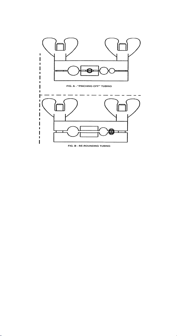
Part Number 8014793 6/18 173
SV1406
USING PINCH-OFF TOOL

174 Part Number 8014793 6/18
This Page Intentionally Left Blank
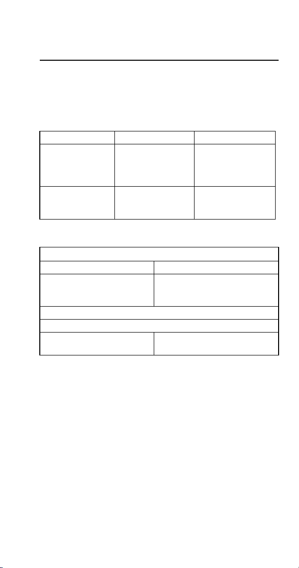
Part Number 8014793 6/18 175
Specifications
MAIN FUSE
The main fuse is 250 Volt, 7 amp.
FAN CYCLE CONTROL
(Self-Contained Air-Cooled Models Only)
HIGH PRESSURE CUTOUT (HPCO) CONTROL
Model Cut-In (Close) Cut-Out (Open)
S300 / S320
S420 / S450
S500 / S600
S850
250 ±5
(1723 kPa ±.34)
(17.23 bar ±.34)
200 ±5
(1517 kPa ±.34)
(15.17 bar ±.34)
S1000 / S1200
S1400 / S1600
S1800
275 psig ±5
(1896 kPa ±34)
(18.96 bar±.34)
225 psig ±5
(1551 kPa ±34)
(15.51 bar ±.34)
Specifications
Cut-Out Cut-In
450 psig ±10
(3103 kPa ±69 31 bar
±.69)
Automatic Reset
(Must be below 300 psig (2068 kPa 20.68 bar) to reset.)
ST3000 R410A Refrigerant Only
600 psig ±10
(3147 kPa ±69)
450 psig ±10
(3103 kPa ±69)

176 Part Number 8014793 6/18
FILTER-DRIERS
The filter-driers used on Manitowoc ice machines are
manufactured to Manitowoc specifications.
The difference between a Manitowoc drier and an off-
the-shelf drier is in filtration. A Manitowoc drier has
dirt-retaining filtration, with fiberglass filters on both the
inlet and outlet ends. This is very important because
ice machines have a back-flushing action that takes
place during every Harvest cycle.
A Manitowoc filter-drier has high moisture and acid
removal capability.
The size of the filter-drier is important. The refrigerant
charge is critical. Using an improperly sized filter-drier
will cause the ice machine to be improperly charged
with refrigerant.
Refer to the parts section in the Electronic Document
Catalog for the current field replacement drier for the
model.
Important
Driers are covered as a warranty part. The drier
must be replaced any time the system is opened for
repairs.
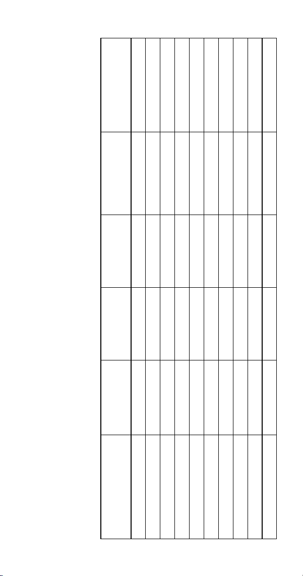
Part Number 8014793 6/18 177
TOTAL SYSTEM REFRIGERANT CHARGE
NOTE: This information is for reference only.
Refer to the ice machine serial number tag to verify the system charge.
Serial plate information overrides information listed on these pages.
All machines listed use R-404A refrigerant except, ST3000 which uses R410A refrigerant.
Model Air Cooled Water Cooled Remote
Additional
Refrigerant for Line
Sets 51’-100’
Maximum
System Charge
S300 18 oz. 11 oz. NA NA NA
S320 20 oz. 15 oz. NA NA NA
S420/S450 21 oz. 14 oz. NA NA NA
S500 Before 110684316 24 oz. 20 oz. 6 lb. 1.5 lb. 7.5 lb.
S500 After 110684316 24 oz. 23 oz. 6 lb. 1.5 lb. 7.5 lb.
S600 32 oz. 28 oz. 6.5 lb. 1.5 lb. 8 lb.
S850 Before 110683282 36 oz. 26 oz. 8.5 lb. 2 lb. 10.5 lb.
S850 After 110683282 34 oz. 26 oz. 8.5 lb. 2 lb. 10.5 lb.
S1000 Before 110697023 36 oz. 26 oz. 8.5 lb. 2 lb. 10.5 lb.
S1000 After 110697023 34 oz. 28 oz. 8.5 lb. 2 lb. 10.5 lb.
178 Part Number 8014793 6/18
S1200 Before 110560252 42 oz. 42 oz. NA NA NA
S1200 After 110560252 42 oz. 34 oz. NA NA NA
S1400 Before
Manufacture Date 0711
44 oz. 30 oz. 11 lb. 2 lb. 13 lb.
S1400 Between
0711 & 0905
Manufacture Date
44 oz. 52 oz. 11 lb. 2 lb. 13 lb.
S1400 After 0905
Manufacture Date
46 oz. 40 oz. 11 lb. 2 lb. 13 lb.
S1600 Before 110566844 48 oz. 46 oz. 11.5 lb. 2 lb. 13.5 lb.
S1600 After 110566844 48 oz. 36 oz. 11.5 lb. 2 lb. 13.5 lb.
S1800 Before 0910
Manufacture Date
52 oz. 48 oz. 12.5 lb. 1 lb. 13.5 lb.
S1800 After 0910
Manufacture Date
52 oz. 40 oz. 12.5 lb. 1 lb. 13.5 lb.
ST3000 - R410A NA 6 lb. NA NA NA
S3300 - R404A NA 6 lb. NA NA NA
Model Air Cooled Water Cooled Remote
Additional
Refrigerant for Line
Sets 51’-100’
Maximum
System Charge

Part Number 8014793 6/18 179
Charts
Cycle Times/24-Hour Ice Production/
Refrigerant Pressure Charts
These charts are used as guidelines to verify correct
ice machine operation.
Accurate collection of data is essential to obtain the
correct diagnosis.
• Refer to “Symptom #2 - Operational Analysis
Table” page 80 for the list of data that must be
collected for refrigeration diagnostics. This list
includes: before beginning service, ice production
check, installation/visual inspection, water system
checklist, ice formation pattern, safety limits,
comparing evaporator inlet/outlet temperatures,
discharge and suction pressure analysis.
• Ice production checks that are within 10% of the
chart are considered normal. This is due to
variances in water and air temperature. Actual
temperatures will seldom match the chart exactly.
• Zero out manifold gauge set before obtaining
pressure readings to avoid mis-diagnosis.
• Discharge and suction pressure are highest at the
beginning of the cycle. Suction pressure will drop
throughout the cycle. Verify the pressures are
within the range indicated.
• Record beginning of freeze cycle suction pressure
one minute after water pump energizes.
• Regular cube production derate is 7%.
• 50Hz production derate is 7%.
• 50Hz regular cube total production derate is 14%.
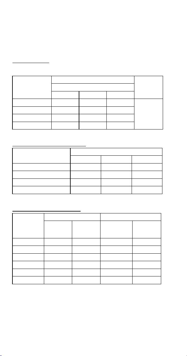
180 Part Number 8014793 6/18
S300 SERIES
S300A
All Self-Contained Air-cooled Models Before Serial
Number 110704351
Characteristics may vary depending on operating conditions.
CYCLE TIMES
Freeze Time + Harvest Time = Total Cycle Time
24 HOUR ICE PRODUCTION
OPERATING PRESSURES
Air Temp.
Entering
Condenser
°F/°C
Freeze Time
Harvest
Time
1
1 Times in minutes
Water Temperature °F/°C
50/10 70/21 90/32
70/21 9.3-11.0 10.4-12.2 11.5-13.5
1-2.5
80/27 10.0-11.8 11.3-13.2 12.6-14.7
90/32 10.8-12.7 12.3-14.4 13.5-15.7
100/38 12.3-14.4 13.5-15.7 14.8-17.3
Air Temp. Entering
Condenser °F/°C
Water Temperature °F/°C
1
1 Based on average ice slab weight of 2.44 - 2.81 lb.
50/10 70/21 90/32
70/21 325 295 270
80/27 305 275 250
90/32 285 255 235
100/38 255 235 215
Air Temp
Entering
Condenser
°F/°C
Freeze Cycle Harvest Cycle
Discharge
Pressure
PSIG
Suction
Pressure
PSIG
1
1 Suction pressure drops gradually throughout the freeze cycle
Discharge
Pressure
PSIG
Suction
Pressure
PSIG
50/10
195-255 50-23 135-160 75-110
70/21 195-260 55-24 135-165 80-110
80/27 220-290 60-25 150-170 90-120
90/32 250-330 70-27 170-195 115-135
100/38 285-370 74-28 200-220 130-155
110/43 330-415 78-30 230-250 150-175
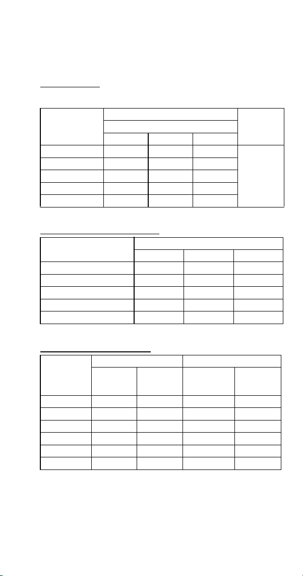
Part Number 8014793 6/18 181
S300A
All Self-Contained Air-cooled Models After Serial Number
110704351
Characteristics may vary depending on operating conditions.
CYCLE TIMES
Freeze Time + Harvest Time = Total Cycle Time
24 HOUR ICE PRODUCTION
OPERATING PRESSURES
Air Temp.
Entering
Condenser
°F/°C
Freeze Time
Harvest
Time
1
1 Times in minutes
Water Temperature °F/°C
50/10 70/21 90/32
70/21 8.7-10.4 9.5-11.3 10.4-12.4
1-2.5
80/27 9.6-11.5 10.6-12.6 11.5-13.7
90/32 10.8-12.9 11.3-13.4 12.9-15.3
100/38 12.3-14.6 13.5-16.0 14.6-17.3
110/43 14.2-16.8 15.4-18.2 16.7-18.7
Air Temp. Entering
Condenser °F/°C
Water Temperature °F/°C
1
1 Based on average ice slab weight of 2.44 - 2.81 lb.
50/10 70/21 90/32
70/21 340 315 290
80/27 310 285 265
90/32 280 270 240
100/38 250 230 215
110/43 220 205 190
Air Temp
Entering
Condenser
°F/°C
Freeze Cycle Harvest Cycle
Discharge
Pressure
PSIG
Suction
Pressure
PSIG
1
1 Suction pressure drops gradually throughout the freeze cycle
Discharge
Pressure
PSIG
Suction
Pressure
PSIG
50/10 195-245 50-23 135-160 75-100
70/21 195-260 60-24 135-165 80-110
80/27 220-290 60-25 150-170 90-120
90/32 250-330 60-27 170-195 115-135
100/38 285-370 70-30 200-220 130-155
110/43 330-415 78-32 230-250 150-175
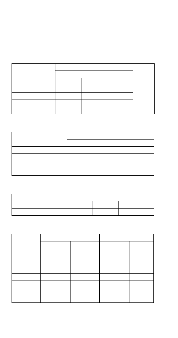
182 Part Number 8014793 6/18
S300W
All Self-Contained Water-cooled Models Before Serial
Number 110704351
Characteristics may vary depending on operating conditions.
CYCLE TIMES
Freeze Time + Harvest Time = Total Cycle Time
24 HOUR ICE PRODUCTION
CONDENSER WATER CONSUMPTION
OPERATING PRESSURES
Air Temp. Around
Ice Machine
°F/°C
Freeze Time
Harvest
Time
1
1 Times in minutes
Water Temperature °F/°C
50/10 70/21 90/32
70/21 9.8-11.6 10.8-12.7 12.0-14.7
1-2.5
80/27 10.0-11.8 11.0-13.0 12.3-14.4
90/32 10.4-12.2 11.5-13.5 12.6-14.7
100/38 10.6-12.5 11.8-13.8 12.8-15.0
Air Temp. Around Ice
Machine °F/°C
Water Temperature °F/°C
1
1 Based on average ice slab weight of 2.44-2.81 lb.
50/10 70/21 90/32
70/21 310 285 260
80/27 305 280 255
90/32 295 270 250
100/38 290 265 245
Air Temp. Around Ice
Machine 90°F/32°C
Water Temperature °F/°C
1
1 Water regulating valve set to maintain 240 PSIG discharge pressure
50/10 70/21 90/32
Gal/24 hours 250 485 2100
Air Temp.
Around Ice
Machine
°F/°C
Freeze Cycle Harvest Cycle
Discharge
Pressure
Suction
Pressure
PSIG
1
1 Suction pressure drops gradually throughout the freeze cycle
Discharge
Pressure
PSIG
Suction
Pressure
PSIG
50/10
235-245 50-24 140-180 75-100
70/21 235-245 60-25 160-190 90-120
80/27 235-265 65-27 160-190 100-130
90/32 235-275 65-27 160-190 100-135
100/38 235-275 65-28 160-190 100-140
110/43 235-275 65-28 170-200 100-140
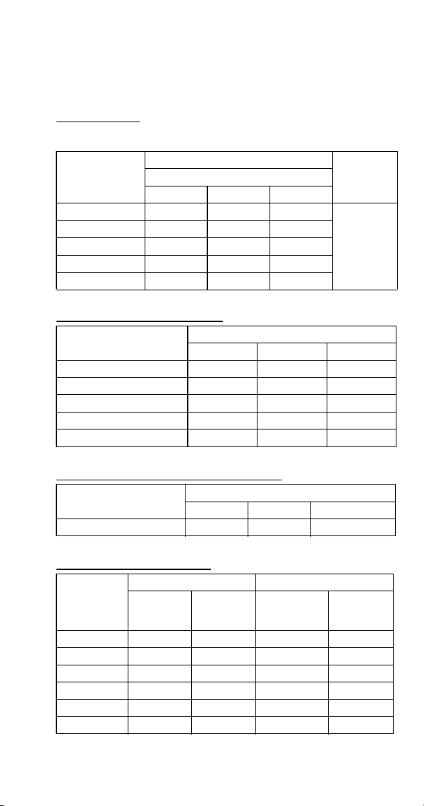
Part Number 8014793 6/18 183
S300W
All Self-Contained Water-cooled Models After Serial
Number 110704351
Characteristics may vary depending on operating conditions.
CYCLE TIMES
Freeze Time + Harvest Time = Total Cycle Time
24 HOUR ICE PRODUCTION
CONDENSER WATER CONSUMPTION
OPERATING PRESSURES
Air Temp.
Entering
Condenser
°F/°C
Freeze Time
Harvest
Time
1
1 Times in minutes
Water Temperature °F/°C
50/10 70/21 90/32
70/21 9.1-10.9 10.0-11.9 11.1-13.2
1-2.5
80/27 9.3-11.1 10.2-12.2 11.3-13.4
90/32 9.5-11.3 10.4-12.4 11.5-13.7
100/38 9.6-11.5 10.6-12.6 11.8-14.0
110/43 9.8-11.7 10.8-12.9 12.1-14.3
Air Temp. Entering
Condenser °F/°C
Water Temperature °F/°C
1
1 Based on average ice slab weight of 2.44 - 2.81 lb.
50/10 70/21 90/32
70/21 325 300 275
80/27 320 295 270
90/32 315 290 265
100/38 310 285 260
110/43 305 280 255
Air Temp. Around Ice
Machine 90°F/32°C
Water Temperature °F/°C
1
1 Water regulating valve set to maintain 240 PSIG discharge pressure
50/10 70/21 90/32
Gal/24 hours 250 510 3300
Air Temp
Entering
Condenser
°F/°C
Freeze Cycle Harvest Cycle
Discharge
Pressure
PSIG
Suction
Pressure
PSIG
1
1 Suction pressure drops gradually throughout the freeze cycle
Discharge
Pressure
PSIG
Suction
Pressure
PSIG
50/10 220-230 50-24 130-170 75-100
70/21 220-230 60-25 140-180 90-100
80/27 225-245 65-26 140-185 90-125
90/32 230-250 65-27 145-185 90-130
100/38 230-260 70-28 145-190 90-135
110/43 235-260 70-28 150-190 90-140
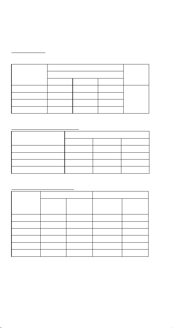
184 Part Number 8014793 6/18
S320 SERIES
S300A
All Self-Contained Air-Cooled Models
Characteristics may vary depending on operating conditions.
CYCLE TIMES
Freeze Time + Harvest Time = Total Cycle Time
24 HOUR ICE PRODUCTION
OPERATING PRESSURES
Air Temp.
Entering
Condenser
°F/°C
Freeze Time
Harvest
Time
1
1 Times in minutes
Water Temperature °F/°C
50/10 70/21 90/32
70/21 12.3-14.0 13.1-14.9 14.1-16.0
1-2.5
80/27 13.1-14.9 14.6-16.6 15.8-18.0
90/32 15.2-17.3 17.2-19.5 18.0-20.4
100/38 18.0-20.4 19.8-22.4 20.8-23.5
Air Temp. Entering
Condenser °F/°C
Water Temperature °F/°C
1
1 Based on average ice slab weight of 3.25 - 3.65 lb.
50/10 70/21 90/32
70/21 340 320 300
80/27 320 290 270
90/32 280 250 240
100/38 240 220 210
Air Temp
Entering
Condenser
°F/°C
Freeze Cycle Harvest Cycle
Discharge
Pressure
PSIG
Suction
Pressure
PSIG
1
1 Suction pressure drops gradually throughout the freeze cycle
Discharge
Pressure
PSIG
Suction
Pressure
PSIG
50/10
195-260 60-34 130-160 80-115
70/21 195-260 70-36 130-165 90-120
80/27 215-295 75-36 140-165 110-125
90/32 240-320 80-38 155-180 120-135
100/38 290-365 90-40 175-215 140-165
110/43 325-415 95-42 200-230 160-185
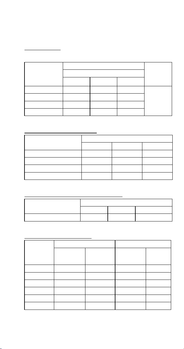
Part Number 8014793 6/18 185
S320 Series
All Self-Contained Water-Cooled Models
Characteristics may vary depending on operating conditions.
CYCLE TIMES
Freeze Time + Harvest Time = Total Cycle Time
24 HOUR ICE PRODUCTION
CONDENSER WATER CONSUMPTION
OPERATING PRESSURES
Air Temp.
Around Ice
Machine
°F/°C
Freeze Time
Harvest
Time
1
1 Times in minutes
Water Temperature °F/°C
50/10 70/21 90/32
70/21 12.7-14.4 13.6-15.5 15.2-17.3
1-2.5
80/27 13.1-14.9 14.1-16.0 15.2-17.3
90/32 13.6-15.5 14.6-16.6 15.8-18.0
100/38 14.1-16.0 15.2-17.3 16.5-18.7
Air Temp. Around Ice
Machine °F/°C
Water Temperature °F/°C
1
1 Based on average ice slab weight of 3.25-3.65 lb.
50/10 70/21 90/32
70/21 330 310 280
80/27 320 300 280
90/32 310 290 270
100/38 300 280 260
Air Temp. Around Ice
Machine 90°F/32°C
Water Temperature °F/°C
1
1 Water regulating valve set to maintain 240 PSIG discharge pressure
50/10 70/21 90/32
Gal/100 lbs. of Ice 90 160 1010
Air Temp.
Around Ice
Machine
°F/°C
Freeze Cycle Harvest Cycle
Discharge
Pressure
PSIG
Suction
Pressure
PSIG
1
1 Suction pressure drops gradually throughout the freeze cycle
Discharge
Pressure
PSIG
Suction
Pressure
PSIG
50/10
235-245 60-38 150-185 85-105
70/21 235-245 68-38 150-190 100-120
80/27 235-250 78-39 155-195 110-145
90/32 235-255 80-40 155-200 115-145
100/38 235-260 82-41 155-205 120-150
110/43 235-265 85-42 155-210 120-150

186 Part Number 8014793 6/18
S420 SERIES
S420A
All Self-Contained Air-cooled Models Before Serial
Number110667970
Characteristics may vary depending on operating conditions.
CYCLE TIMES
Freeze Time + Harvest Time = Total Cycle Time
24 HOUR ICE PRODUCTION
OPERATING PRESSURES
Air Temp.
Entering
Condenser
°F/°C
Freeze Time
Harvest
Time
1
1 Times in minutes
Water Temperature °F/°C
50/10 70/21 90/32
70/21 11.9-12.7 13.1-14.0 14.6-15.5
1-2.5
80/27 13.1-14.0 14.3-15.2 16.0-17.0
90/32 14.6-15.5 16.3-17.4 17.3-18.4
100/38 16.3-17.4 17.3-18.4 18.9-20.1
110/43 18.1-19.2 19.8-21.0 21.3-22.6
Air Temp. Entering
Condenser °F/°C
Water Temperature °F/°C
1
1 Based on average ice slab weight of 3.4 - 3.6 lb.
50/10 70/21 90/32
70/21 365 335 305
80/27 335 310 280
90/32 305 275 260
100/38 275 260 240
110/43 250 230 215
Air Temp
Entering
Condenser
°F/°C
Freeze Cycle Harvest Cycle
Discharge
Pressure
PSIG
Suction
Pressure
PSIG
1
1 Suction pressure drops gradually throughout the freeze cycle
Discharge
Pressure
PSIG
Suction
Pressure
PSIG
50/10
195-255 50-30 125-185 70-90
70/21 195-270 60-30 135-190 80-115
80/27 220-285 62-32 135-195 80-115
90/32 250-320 70-34 175-195 85-115
100/38 290-390 75-35 190-215 115-140
110/43 320-400 80-37 225-250 130-170
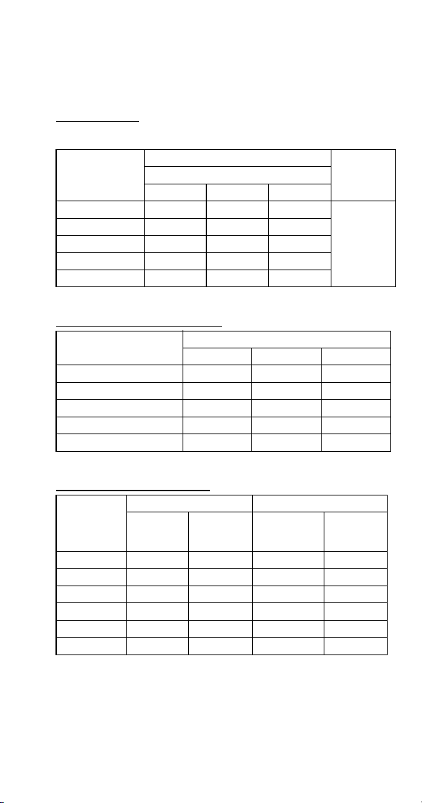
Part Number 8014793 6/18 187
S420A
All Self-Contained Air-cooled Models After Serial Number
110667970
Characteristics may vary depending on operating conditions.
CYCLE TIMES
Freeze Time + Harvest Time = Total Cycle Time
24 HOUR ICE PRODUCTION
OPERATING PRESSURES
Air Temp.
Entering
Condenser
°F/°C
Freeze Time
Harvest
Time
1
1 Times in minutes
Water Temperature °F/°C
50/10 70/21 90/32
70/21 11.9-12.7 13.1-14.0 14.6-15.5
1-2.5
80/27 13.1-14.0 14.3-15.2 16.0-17.0
90/32 14.6-15.5 16.3-17.4 17.3-18.4
100/38 16.3-17.4 17.3-18.4 18.9-20.1
110/43 18.1-19.2 19.8-21.0 21.3-22.6
Air Temp. Entering
Condenser °F/°C
Water Temperature °F/°C
1
1 Based on average ice slab weight of 3.4 - 3.6 lb.
50/10 70/21 90/32
70/21 365 335 305
80/27 335 310 280
90/32 305 275 260
100/38 275 260 240
110/43 250 230 215
Air Temp
Entering
Condenser
°F/°C
Freeze Cycle Harvest Cycle
Discharge
Pressure
PSIG
Suction
Pressure
PSIG
1
1 Suction pressure drops gradually throughout the freeze cycle
Discharge
Pressure
PSIG
Suction
Pressure
PSIG
50/10
195-255 50-30 125-185 70-90
70/21 195-270 60-30 135-190 80-115
80/27 220-285 62-32 135-195 80-115
90/32 250-320 70-34 175-195 85-115
100/38 290-390 75-35 190-215 115-140
110/43 320-400 80-37 225-250 130-170
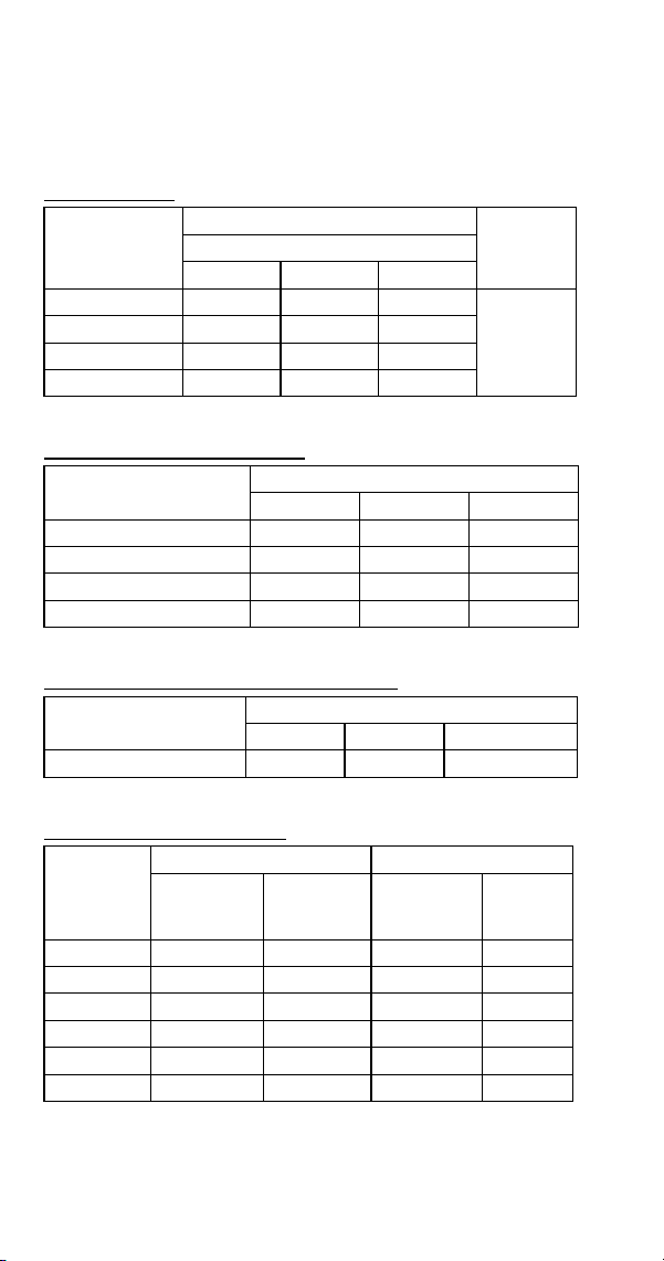
188 Part Number 8014793 6/18
S420W
All Self-Contained Water-cooled Models Before Serial
Number 110667970
Characteristics vary depending on operating conditions.
CYCLE TIMES
24 HOUR ICE PRODUCTION
CONDENSER WATER CONSUMPTION
OPERATING PRESSURES
Air Temp.
Around Ice
Machine
°F/°C
Freeze Time
Harvest
Time
1
1 Times in minutes
Water Temperature °F/°C
50/10 70/21 90/32
70/21 12.7-13.5 11.2-15.2 12.7-13.5
1-2.5
80/27 13.1-14.0 14.6-15.5 12.9-17.7
90/32 13.3-14.2 11.7-15.8 13.1-18.1
110/43 14.0-15.0 15.4-16.4 17.7-18.8
Air Temp. Around Ice
Machine °F/°C
Water Temperature °F/°C
1
1 Based on average ice slab weight of 3.40-3.60 lb.
50/10 70/21 90/32
70/21 345 310 275
80/27 335 305 270
90/32 330 300 265
110/43 315 290 255
Air Temp. Around Ice
Machine 90°F/32°C
Water Temperature °F/°C
1
1 Water regulating valve set to maintain 240 PSIG discharge pressure
50/10 70/21 90/32
Gal/100 lbs. of Ice NA 200 NA
Air Temp.
Around Ice
Machine
°F/°C
Freeze Cycle Harvest Cycle
Discharge
Pressure
PSIG
Suction
Pressure
PSIG
1
1 Suction pressure drops gradually throughout the freeze cycle
Discharge
Pressure
PSIG
Suction
Pressure
PSIG
50/10
235-240 48-29 150-185 70-95
70/21 235-265 52-30 160-190 85-100
80/27 235-265 56-30 170-190 90-110
90/32 235-270 62-31 170-195 95-115
100/38 235-275 65-31 170-200 100-120
110/43 240-280 65-32 170-205 100-120

Part Number 8014793 6/18 189
S420W
All Self-Contained Water-cooled Models After Serial
Number 110667970
Characteristics vary depending on operating conditions.
CYCLE TIMES
24 HOUR ICE PRODUCTION
CONDENSER WATER CONSUMPTION
OPERATING PRESSURES
Air Temp.
Around Ice
Machine
°F/°C
Freeze Time
Harvest
Time
1
1 Times in minutes
Water Temperature °F/°C
50/10 70/21 90/32
70/21 12.7-13.5 11.2-15.2 12.7-13.5
1-2.5
80/27 13.1-14.0 14.6-15.5 12.9-17.7
90/32 13.3-14.2 11.7-15.8 13.1-18.1
110/43 14.0-15.0 15.4-16.4 17.7-18.8
Air Temp. Around Ice
Machine °F/°C
Water Temperature °F/°C
1
1 Based on average ice slab weight of 3.40-3.60 lb.
50/10 70/21 90/32
70/21 345 310 275
80/27 335 305 270
90/32 330 300 265
110/43 315 290 255
Air Temp. Around Ice
Machine 90°F/32°C
Water Temperature °F/°C
1
1 Water regulating valve set to maintain 240 PSIG discharge pressure
50/10 70/21 90/32
Gal/100 lbs. of Ice NA 200 NA
Air Temp.
Around Ice
Machine
°F/°C
Freeze Cycle Harvest Cycle
Discharge
Pressure
PSIG
Suction
Pressure
PSIG
1
1 Suction pressure drops gradually throughout the freeze cycle
Discharge
Pressure
PSIG
Suction
Pressure
PSIG
50/10
235-240 48-29 150-185 70-95
70/21 235-265 52-30 160-190 85-100
80/27 235-265 56-30 170-190 90-110
90/32 235-270 62-31 170-195 95-115
100/38 235-275 65-31 170-200 100-120
110/43 240-280 65-32 170-205 100-120
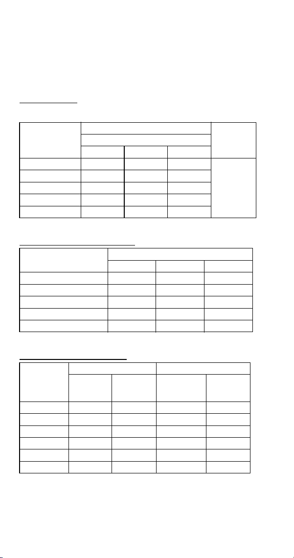
190 Part Number 8014793 6/18
S450 SERIES
S450A
All Self-Contained Air-cooled Models Before Serial
Number 110670157
Characteristics may vary depending on operating conditions.
CYCLE TIMES
Freeze Time + Harvest Time = Total Cycle Time
24 HOUR ICE PRODUCTION
OPERATING PRESSURES
Air Temp.
Entering
Condenser
°F/°C
Freeze Time
Harvest
Time
1
1 Times in minutes
Water Temperature °F/°C
50/10 70/21 90/32
70/21 11.9-12.7 13.1-14.0 14.6-15.5
1-2.5
80/27 13.1-14.0 14.3-15.2 16.0-17.0
90/32 14.6-15.5 16.3-17.4 17.3-18.4
100/38 16.3-17.4 17.3-18.4 18.9-20.1
110/43 18.1-19.2 19.8-21.0 21.3-22.6
Air Temp. Entering
Condenser °F/°C
Water Temperature °F/°C
1
1 Based on average ice slab weight of 3.4 - 3.6 lb.
50/10 70/21 90/32
70/21 365 335 305
80/27 335 310 280
90/32 305 275 260
100/38 275 260 240
110/43 250 230 215
Air Temp
Entering
Condenser
°F/°C
Freeze Cycle Harvest Cycle
Discharge
Pressure
PSIG
Suction
Pressure
PSIG
1
1 Suction pressure drops gradually throughout the freeze cycle
Discharge
Pressure
PSIG
Suction
Pressure
PSIG
50/10
195-255 50-30 125-185 70-90
70/21 195-270 60-30 135-190 80-115
80/27 220-285 62-32 135-195 80-115
90/32 250-320 70-34 175-195 85-115
100/38 290-390 75-35 190-215 115-140
110/43 320-400 80-37 225-250 130-170

Part Number 8014793 6/18 191
S450A
All Self-Contained Air-cooled Models After Serial Number
110670157
Characteristics may vary depending on operating conditions.
CYCLE TIMES
Freeze Time + Harvest Time = Total Cycle Time
24 HOUR ICE PRODUCTION
OPERATING PRESSURES
Air Temp.
Entering
Condenser
°F/°C
Freeze Time
Harvest
Time
1
1 Times in minutes
Water Temperature °F/°C
50/10 70/21 90/32
70/21 11.9-12.7 13.1-14.0 14.6-15.5
1-2.5
80/27 13.1-14.0 14.3-15.2 16.0-17.0
90/32 14.6-15.5 16.3-17.4 17.3-18.4
100/38 16.3-17.4 17.3-18.4 18.9-20.1
110/43 18.1-19.2 19.8-21.0 21.3-22.6
Air Temp. Entering
Condenser °F/°C
Water Temperature °F/°C
1
1 Based on average ice slab weight of 3.4 - 3.6 lb.
50/10 70/21 90/32
70/21 365 335 305
80/27 335 310 280
90/32 305 275 260
100/38 275 260 240
110/43 250 230 215
Air Temp
Entering
Condenser
°F/°C
Freeze Cycle Harvest Cycle
Discharge
Pressure
PSIG
Suction
Pressure
PSIG
1
1 Suction pressure drops gradually throughout the freeze cycle
Discharge
Pressure
PSIG
Suction
Pressure
PSIG
50/10
195-255 50-30 125-185 70-90
70/21 195-270 60-30 135-190 80-115
80/27 220-285 62-32 135-195 80-115
90/32 250-320 70-34 175-195 85-115
100/38 290-390 75-35 190-215 115-140
110/43 320-400 80-37 225-250 130-170

192 Part Number 8014793 6/18
S450W
All Self-Contained Water-cooled Models Before Serial
Number 110670157
Characteristics vary depending on operating conditions.
CYCLE TIMES
24 HOUR ICE PRODUCTION
CONDENSER WATER CONSUMPTION
OPERATING PRESSURES
Air Temp.
Around Ice
Machine
°F/°C
Freeze Time
Harvest
Time
1
1 Times in minutes
Water Temperature °F/°C
50/10 70/21 90/32
70/21 12.7-13.5 11.2-15.2 12.7-13.5
1-2.5
80/27 13.1-14.0 14.6-15.5 12.9-17.7
90/32 13.3-14.2 11.7-15.8 13.1-18.1
110/43 14.0-15.0 15.4-16.4 17.7-18.8
Air Temp. Around Ice
Machine °F/°C
Water Temperature °F/°C
1
1 Based on average ice slab weight of 3.40-3.60 lb.
50/10 70/21 90/32
70/21 345 310 275
80/27 335 305 270
90/32 330 300 265
110/43 315 290 255
Air Temp. Around Ice
Machine 90°F/32°C
Water Temperature °F/°C
1
1 Water regulating valve set to maintain 240 PSIG discharge pressure
50/10 70/21 90/32
Gal/100 lbs. of Ice NA 200 NA
Air Temp.
Around Ice
Machine
°F/°C
Freeze Cycle Harvest Cycle
Discharge
Pressure
PSIG
Suction
Pressure
PSIG
1
1 Suction pressure drops gradually throughout the freeze cycle
Discharge
Pressure
PSIG
Suction
Pressure
PSIG
50/10
235-240 48-29 150-185 70-95
70/21 235-265 52-30 160-190 85-100
80/27 235-265 56-30 170-190 90-110
90/32 235-270 62-31 170-195 95-115
100/38 235-275 65-31 170-200 100-120
110/43 240-280 65-32 170-205 100-120
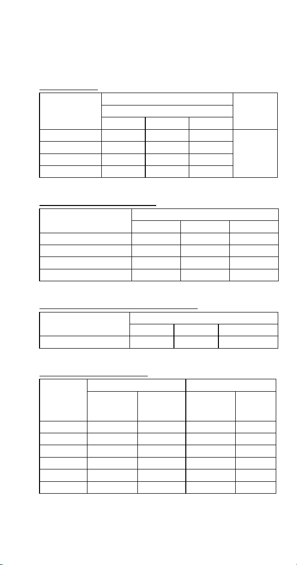
Part Number 8014793 6/18 193
S450W
All Self-Contained Water-cooled Models After Serial
Number 110670157
Characteristics vary depending on operating conditions.
CYCLE TIMES
24 HOUR ICE PRODUCTION
CONDENSER WATER CONSUMPTION
OPERATING PRESSURES
Air Temp.
Around Ice
Machine
°F/°C
Freeze Time
Harvest
Time
1
1 Times in minutes
Water Temperature °F/°C
50/10 70/21 90/32
70/21 12.7-13.5 11.2-15.2 12.7-13.5
1-2.5
80/27 13.1-14.0 14.6-15.5 12.9-17.7
90/32 13.3-14.2 11.7-15.8 13.1-18.1
110/43 14.0-15.0 15.4-16.4 17.7-18.8
Air Temp. Around Ice
Machine °F/°C
Water Temperature °F/°C
1
1 Based on average ice slab weight of 3.40-3.60 lb.
50/10 70/21 90/32
70/21 345 310 275
80/27 335 305 270
90/32 330 300 265
110/43 315 290 255
Air Temp. Around Ice
Machine 90°F/32°C
Water Temperature °F/°C
1
1 Water regulating valve set to maintain 240 PSIG discharge pressure
50/10 70/21 90/32
Gal/100 lbs. of Ice NA 200 NA
Air Temp.
Around Ice
Machine
°F/°C
Freeze Cycle Harvest Cycle
Discharge
Pressure
PSIG
Suction
Pressure
PSIG
1
1 Suction pressure drops gradually throughout the freeze cycle
Discharge
Pressure
PSIG
Suction
Pressure
PSIG
50/10
235-240 48-29 150-185 70-95
70/21 235-265 52-30 160-190 85-100
80/27 235-265 56-30 170-190 90-110
90/32 235-270 62-31 170-195 95-115
100/38 235-275 65-31 170-200 100-120
110/43 240-280 65-32 170-205 100-120
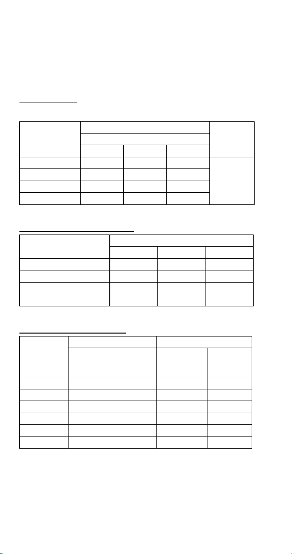
194 Part Number 8014793 6/18
S500 SERIES
S500A
All Self-Contained Air-cooled Models Before Serial
Number 110684316
Characteristics may vary depending on operating conditions.
CYCLE TIMES
Freeze Time + Harvest Time = Total Cycle Time
24 HOUR ICE PRODUCTION
OPERATING PRESSURES
Air Temp.
Entering
Condenser
°F/°C
Freeze Time
Harvest
Time
1
1 Times in minutes
Water Temperature °F/°C
50/10 70/21 90/32
70/21 9.5-11.2 11.1-13.1 12.0-14.0
1-2.5
80/27 10.4-12.2 12.3-14.4 12.6-14.8
90/32 11.4-13.4 13.3-15.6 14.1-16.5
100/38 13.7-16.0 15.0-17.5 15.9-18.6
Air Temp. Entering
Condenser °F/°C
Water Temperature °F/°C
1
1 Based on average ice slab weight of 4.12-4.75 lb.
50/10 70/21 90/32
70/21 540 470 440
80/27 500 430 420
90/32 460 400 380
100/38 390 360 340
Air Temp
Entering
Condenser
°F/°C
Freeze Cycle Harvest Cycle
Discharge
Pressure
PSIG
Suction
Pressure
PSIG
1
1 Suction pressure drops gradually throughout the freeze cycle
Discharge
Pressure
PSIG
Suction
Pressure
PSIG
50/10
195-255 44-26 130-160 75-90
70/21 195-255 47-28 135-160 80-95
80/27 220-295 50-29 160-175 90-105
90/32 250-325 55-31 175-205 105-120
100/38 270-370 60-32 200-225 120-145
110/43 290-425 75-36 220-260 150-165

Part Number 8014793 6/18 195
SD0502A
Dice Cube, Self-Contained Air-cooled After Serial
Number 110684316
Characteristics may vary depending on operating conditions.
CYCLE TIMES
Freeze Time + Harvest Time = Total Cycle Time
24 HOUR ICE PRODUCTION
OPERATING PRESSURES
Air Temp.
Entering
Condenser
°F/°C
Freeze Time
Harvest
Time
1
1 Times in minutes
Water Temperature °F/°C
50/10 70/21 90/32
35/2 to
70/21
10.4-12.1 11.5-13.3 12.7-14.7
0.75-2.0
90/32 12.8-14.9 13.5-15.6 15.5-18.0
100/38 14.5-16.7 15.8-18.2 17.6-20.3
110/43 16.5-19.1 18.2-21.0 19.9-22.9
Air Temp. Entering
Condenser
°F/°C
Water Temperature °F/°C
12
1 Based on average ice slab weight of 4.38 - 5.0 lb
2 230/50/1 is approximately 12% lower than 230/60/1
50/10 70/21 90/32
35/2 to 70/21 530 485 445
90/32 440 420 370
100/38 395 365 330
110/43 350 320 295
Air Temp.
Entering
Condenser
°F/°C
Freeze Cycle Harvest Cycle
Discharge
Pressure
PSIG
Suction
Pressure
PSIG
1
1 Suction pressure drops gradually throughout the freeze cycle
Discharge
Pressure
PSIG
Suction
Pressure
PSIG
50/10 200-255 50-33 120-145 70-100
70/21 205-260 70-35 120-150 80-110
80/27 210-270 70-36 145-165 80-110
90/32 270-325 70-37 165-190 100-120
100/38 300-400 90-38 210-230 130-150
110/43 330-425 100-38 220-240 140-160
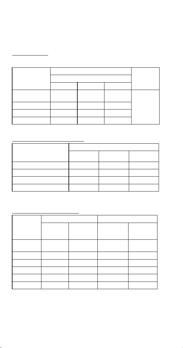
196 Part Number 8014793 6/18
SY0504A
Half Dice Cube, Self-Contained Air-cooled After Serial
Number 110684316
Characteristics may vary depending on operating conditions.
CYCLE TIMES
Freeze Time + Harvest Time = Total Cycle Time
24 HOUR ICE PRODUCTION
OPERATING PRESSURES
Air Temp.
Entering
Condenser
°F/°C
Freeze Time
Harvest
Time
1
1 Times in minutes
Water Temperature °F/°C
50/10 70/21 90/32
35/2 to
70/21
9.8-11.4 10.9-12.6 12.1-14.0
0.75-2.0
90/32 12.2-14.2 12.8-14.9 14.7-17.0
100/38 13.9-16.1 15.1-17.4 16.5-19.1
110/43 16.0-18.5 17.3-20.0 18.8-21.7
Air Temp. Entering
Condenser
°F/°C
Water Temperature °F/°C
12
1 Based on average ice slab weight of 4.38 - 5.0 lb
2 230/50/1 is approximately 12% lower than 230/60/1
50/10 70/21 90/32
35/2 to 70/21 560 510 465
90/32 560 440 390
100/38 410 380 350
110/43 360 335 310
Air Temp.
Entering
Condenser
°F/°C
Freeze Cycle Harvest Cycle
Discharge
Pressure
PSIG
Suction
Pressure
PSIG
1
1 Suction pressure drops gradually throughout the freeze cycle
Discharge
Pressure
PSIG
Suction
Pressure
PSIG
-20/-29 to
50/10
200-255 50-33 120-145 70-100
70/21 205-260 70-35 130-150 80-110
80/27 210-270 70-36 145-165 80-110
90/32 270-325 70-37 165-190 100-120
100/38 300-400 90-38 210-230 130-150
110/43 330-425 100-38 220-240 140-160

Part Number 8014793 6/18 197
S500W
All Self-Contained Water-cooled Models Before Serial
Number 110684316
Characteristics may vary depending on operating conditions.
CYCLE TIMES
Freeze Time + Harvest Time = Total Cycle Time
24 HOUR ICE PRODUCTION
CONDENSER WATER CONSUMPTION
OPERATING PRESSURES
Air Temp.
Around Ice
Machine °F/°C
Freeze Time
Harvest
Time
1
1 Times in minutes
Water Temperature °F/°C
50/10 70/21 90/32
70/21 9.3-10.9 10.6-12.5 12.0-14.0
1-2.5
80/27 9.7-11.4 10.9-12.8 12.3-14.4
90/32 9.9-11.7 10.9-12.8 12.6-14.8
100/38 10.1-11.9 11.4-13.4 13.0-15.2
Air Temp. Around Ice
Machine °F/°C
Water Temperature °F/°C
1
1 Based on average ice slab weight of 4.12-4.75 lb.
50/10 70/21 90/32
70/21 550 490 440
80/27 530 480 430
90/32 520 480 420
100/38 510 460 410
Air Temp. Around Ice
Machine 90°F/32.2°C
Water Temperature °F/°C
1
1 Water regulating valve set to maintain 240 PSIG discharge pressure
50/10 70/21 90/32
Gal/100 lbs. of Ice 87 138 458
Air Temp.
Around Ice
Machine
°F/°C
Freeze Cycle Harvest Cycle
Discharge
Pressure
PSIG
Suction
Pressure
PSIG
1
1 Suction pressure drops gradually throughout the freeze cycle
Discharge
Pressure
PSIG
Suction
Pressure
PSIG
50/10
235-240 45-30 160-180 80-115
70/21 235-260 45-30 165-195 90-120
80/27 235-265 46-31 165-195 95-120
90/32 235-265 46-32 165-195 95-120
100/38 235-270 48-32 165-200 100-125
110/43 235-270 50-32 165-205 105-125
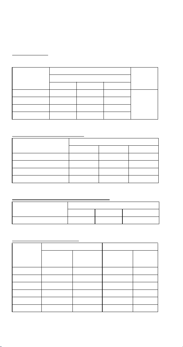
198 Part Number 8014793 6/18
SD0503W
Dice Cube, Self-Contained Water-cooled Models After
Serial Number 110684316
Characteristics may vary depending on operating conditions.
CYCLE TIMES
Freeze Time + Harvest Time = Total Cycle Time
24 HOUR ICE PRODUCTION
CONDENSER WATER CONSUMPTION
OPERATING PRESSURES
Air Temp.
Around Ice
Machine °F/°C
Freeze Time
Harvest
Time
1
1 Times in minutes
Water Temperature °F/°C
50/10 70/21 90/32
35/2 to 70/21 10.0-11.6 11.1-12.9 12.8-14.9
0.75-2.0
90/32 10.4-12.1 11.9-13.8 13.3-15.4
100/38 10.6-12.3 12.1-14.0 13.7-15.8
110/43 10.9-12.6 12.2-14.2 14.1-16.3
Air Temp. Around Ice
Machine °F/°C
Water Temperature °F/°C
1
1 Based on average ice slab weight of 4.38 - 5.0 lb
50/10 70/21 90/32
35/2 to 70/21 550 500 440
90/32 530 470 425
100/38 520 465 415
110/43 510 460 405
Air Temp. Around Ice
Machine 90°F/32.2°C
Water Temperature °F/°C
1
1 Water regulating valve set to maintain 240 PSIG discharge pressure
50/10 70/21 90/32
Gal/100 lbs. of Ice 355 700 3160
Air Temp.
Around Ice
Machine
°F/°C
Freeze Cycle Harvest Cycle
Discharge
Pressure
PSIG
Suction
Pressure
PSIG
1
1 Suction pressure drops gradually throughout the freeze cycle
Discharge
Pressure
PSIG
Suction
Pressure
PSIG
50/10 220-230 50-33 125-140 75-110
70/21 220-230 60-33 130-150 95-120
80/27 220-240 65-33 130-160 95-120
90/32 230-250 70-33 170-190 95-120
100/38 235-250 75-33 170-190 95-120
110/43 235-250 75-33 170-190 95-120
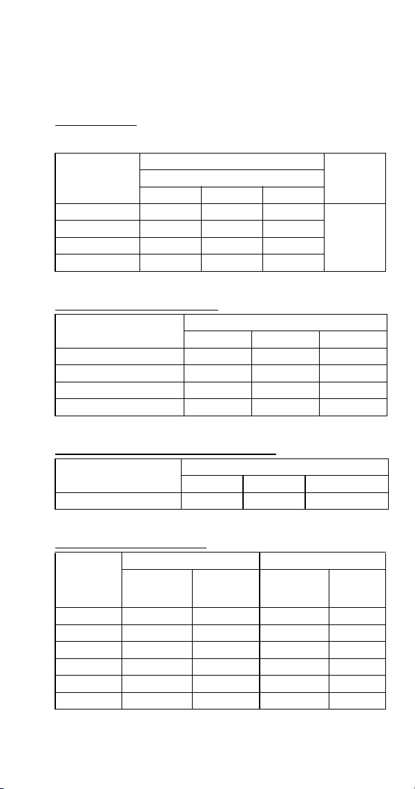
Part Number 8014793 6/18 199
SY0505W
Half Dice Cube, Self-Contained Water-cooled After Serial
Number 110684316
Characteristics may vary depending on operating conditions.
CYCLE TIMES
Freeze Time + Harvest Time = Total Cycle Time
24 HOUR ICE PRODUCTION
CONDENSER WATER CONSUMPTION
OPERATING PRESSURES
Air Temp.
Around Ice
Machine °F/°C
Freeze Time
Harvest
Time
1
1 Times in minutes
Water Temperature °F/°C
50/10 70/21 90/32
35/2 to 70/21 10.0-11.6 11.1-12.9 12.8-14.9
0.75-2.0
90/32 10.4-12.1 11.5-13.3 13.3-15.4
100/38 10.5-12.2 11.9-13.8 13.5-15.6
110/43 10.7-12.5 12.1-14.0 13.9-16.1
Air Temp. Around Ice
Machine °F/°C
Water Temperature °F/°C
1
1 Based on average ice slab weight of 4.38 - 5.0 lb
50/10 70/21 90/32
35/2 to 70/21 550 500 440
90/32 530 485 425
100/38 525 470 420
110/43 515 465 410
Air Temp. Around Ice
Machine 90°F/32.2°C
Water Temperature °F/°C
1
1 Water regulating valve set to maintain 240 PSIG discharge pressure
50/10 70/21 90/32
Gal/100 lbs. of Ice 355 700 3160
Air Temp.
Around Ice
Machine
°F/°C
Freeze Cycle Harvest Cycle
Discharge
Pressure
PSIG
Suction
Pressure
PSIG
1
1 Suction pressure drops gradually throughout the freeze cycle
Discharge
Pressure
PSIG
Suction
Pressure
PSIG
50/10 220-230 50-33 125-140 75-110
70/21 220-230 60-33 130-150 95-120
80/27 220-240 65-33 130-160 95-120
90/32 230-250 70-33 170-190 95-120
100/38 235-250 75-33 170-190 95-120
110/43 235-250 75-33 170-190 95-120
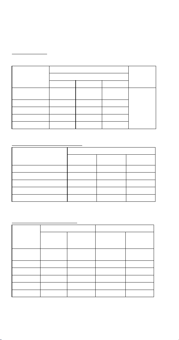
200 Part Number 8014793 6/18
S500N
All Remote Air-cooled Condenser Models Before Serial
Number 110684316
Characteristics may vary depending on operating conditions.
CYCLE TIMES
Freeze Time + Harvest Time = Total Cycle Time
24 HOUR ICE PRODUCTION
OPERATING PRESSURES
Air Temp.
Entering
Condenser
°F/°C
Freeze Time
Harvest
Time
1
1 Times in minutes
Water Temperature °F/°C
50/10 70/21 90/32
-20/-29 to
70/21
9.9-11.7 11.1-13.1 12.6-14.8
1-2.5
80/27 9.9-11.7 11.4-13.4 12.6-14.8
90/32 10.1-11.9 11.4-13.4 12.6-14.8
100/38 10.9-12.8 12.3-14.4 13.3-15.6
110/43 12.0-14.0 13.3-15.6 14.1-16.5
Air Temp. Entering
Condenser
°F/°C
Water Temperature °F/°C
12
1 Based on average ice slab weight of 4.12 - 4.75 lb
2 Ratings with JC0495 condenser dice or half dice cubes
50/10 70/21 90/32
-20/-29 to 70/21 520 470 420
80/27 520 460 420
90/32 510 460 420
100/38 480 430 400
110/43 440 400 380
Air Temp.
Entering
Condenser
°F/°C
Freeze Cycle Harvest Cycle
Discharge
Pressure
PSIG
Suction
Pressure
PSIG
1
1 Suction pressure drops gradually throughout the freeze cycle
Discharge
Pressure
PSIG
Suction
Pressure
PSIG
-20/-29 to
50/10
210-240 42-29 105-160 75-100
70/21 235-250 48-31 105-165 85-100
80/27 245-260 50-32 110-165 85-100
90/32 250-270 52-33 110-170 90-105
100/38 265-315 60-34 125-175 90-110
110/43 295-365 62-35 130-185 95-115

Part Number 8014793 6/18 201
SD0592N
Dice Cube, Remote Air-cooled Condenser Models After
Serial Number 110684316
Characteristics may vary depending on operating conditions.
CYCLE TIMES
Freeze Time + Harvest Time = Total Cycle Time
24 HOUR ICE PRODUCTION
OPERATING PRESSURES
Air Temp.
Entering
Condenser
°F/°C
Freeze Time
Harvest
Time
1
1 Times in minutes
Water Temperature °F/°C
50/10 70/21 90/32
-20/-29 to
70/21
11.6-13.5 12.7-14.7 13.7-15.8
0.75-2.0
90/32 12.4-14.3 13.3-15.4 14.7-17.0
100/38 12.8-14.9 14.1-16.3 15.3-17.7
110/43 13.3-15.4 14.5-16.7 16.0-18.5
Air Temp. Entering
Condenser
°F/°C
Water Temperature °F/°C
1
1 Based on average ice slab weight of 4.38 - 5.0 lb
50/10 70/21 90/32
-20/-29 to 70/21 480 445 415
90/32 455 425 390
100/38 440 405 375
110/43 425 395 360
Air Temp.
Entering
Condenser
°F/°C
Freeze Cycle Harvest Cycle
Discharge
Pressure
PSIG
Suction
Pressure
PSIG
1
1 Suction pressure drops gradually throughout the freeze cycle
Discharge
Pressure
PSIG
Suction
Pressure
PSIG
50/10 205-220 50-32 100-150 75-100
70/21 240-260 60-32 110-160 75-100
80/27 240-270 60-32 110-160 75-100
90/32 250-270 60-32 120-160 80-100
100/38 300-375 85-35 130-170 80-100
110/43 310-375 90-36 130-170 80-100

202 Part Number 8014793 6/18
SY0594N
Half Dice Cube, Remote Air-cooled Condenser Models
After Serial Number 110684316
Characteristics may vary depending on operating conditions.
CYCLE TIMES
Freeze Time + Harvest Time = Total Cycle Time
24 HOUR ICE PRODUCTION
OPERATING PRESSURES
Air Temp.
Entering
Condenser
°F/°C
Freeze Time
Harvest
Time
1
1 Times in minutes
Water Temperature °F/°C
50/10 70/21 90/32
-20/-29 to
70/21
10.9-12.6 12.1-14.0 13.3-15.4
0.75-2.0
90/32 11.8-13.7 12.5-14.5 14.3-16.5
100/38 12.2-14.2 13.5-15.6 14.9-17.2
110/43 12.8-14.9 14.1-16.3 15.5-18.0
Air Temp. Entering
Condenser
°F/°C
Water Temperature °F/°C
1
1 Based on average ice slab weight of 4.38 - 5.0 lb
50/10 70/21 90/32
-20/-29 to 70/21 510 465 425
90/32 475 450 400
100/38 460 420 385
110/43 440 405 370
Air Temp.
Entering
Condenser
°F/°C
Freeze Cycle Harvest Cycle
Discharge
Pressure
PSIG
Suction
Pressure
PSIG
1
1 Suction pressure drops gradually throughout the freeze cycle
Discharge
Pressure
PSIG
Suction
Pressure
PSIG
50/10 205-220 50-32 100-150 75-100
70/21 240-260 60-32 110-160 75-100
80/27 240-270 60-32 110-160 75-100
90/32 250-270 60-32 120-160 80-100
100/38 300-375 85-35 130-170 80-100
110/43 310-375 90-36 130-170 80-100

Part Number 8014793 6/18 203
S600 SERIES
S600A
All Self-Contained Air-Cooled Models
Characteristics may vary depending on operating conditions.
CYCLE TIMES
Freeze Time + Harvest Time = Total Cycle Time
24 HOUR ICE PRODUCTION
OPERATING PRESSURES
Air Temp.
Entering
Condenser
°F/°C
Freeze Time Harvest
Time
1
1 Times in minutes
Water Temperature °F/°C
50/10.0 70/21.1 90/32.2
70/21 7.6-9.0 8.4-9.9 9.1-10.7
1-2.5
80/27 7.8-9.2 8.8-10.3 9.3-10.9
90/32 8.6-10.1 9.5-11.2 10.2-11.9
100/38 9.9-11.7 10.9-12.8 11.4-13.4
Air Temp. Entering
Condenser °F/°C
Water Temperature °F/°C
1
1 Based on average ice slab weight of 4.12-4.75 lb.
50/10.0 70/21.1 90/32.2
70/21 650 600 560
80/27 640 580 550
90/32 590 540 510
100/38 520 480 460
Air Temp
Entering
Condenser
°F/°C
Freeze Cycle Harvest Cycle
Discharge
Pressure
PSIG
Suction
Pressure
PSIG
1
1 Suction pressure drops gradually throughout the freeze cycle
Discharge
Pressure
PSIG
Suction
Pressure
PSIG
50/10 220-255 45-27 140-160 60-80
70/21 220-270 45-28 145-170 70-90
80/27 230-300 50-30 165-185 75-95
90/32 265-345 54-32 180-215 80-105
100/38 300-395 60-35 210-245 85-120
110/43 340-430 65-39 240-280 100-140
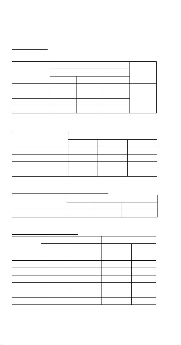
204 Part Number 8014793 6/18
S600W
All Self-Contained Water-Cooled Models
Characteristics may vary depending on operating conditions.
CYCLE TIMES
Freeze Time + Harvest Time = Total Cycle Time
24 HOUR ICE PRODUCTION
CONDENSER WATER CONSUMPTION
OPERATING PRESSURES
Air Temp.
Around Ice
Machine °F/°C
Freeze Time
Harvest
Time
1
1 Times in minutes
Water Temperature °F/°C
50/10 70/21 90/32
70/21 7.6-9.0 7.9-9.4 8.6-10.1
1-2.5
80/27 7.8-9.2 8.1-9.5 8.8-10.3
90/32 7.9-9.4 8.2-9.7 8.8-10.3
100/38 8.1-9.5 8.4-9.9 9.1-10.7
Air Temp. Around Ice
Machine °F/°C
Water Temperature °F/°C
1
1 Based on average ice slab weight of 4.12-4.75 lb.
50/10 70/21 90/32
70/21 650 630 590
80/27 640 620 580
90/32 630 610 580
100/38 620 600 560
Air Temp. Around Ice
Machine 90°F/32°C
Water Temperature °F/°C
1
1 Water regulating valve set to maintain 240 PSIG discharge pressure
50/10 70/21 90/32
Gal/100 lbs. of Ice 110 170 870
Air Temp.
Around Ice
Machine
°F/°C
Freeze Cycle Harvest Cycle
Discharge
Pressure
PSIG
Suction
Pressure
PSIG
1
1 Suction pressure drops gradually throughout the freeze cycle
Discharge
Pressure
PSIG
Suction
Pressure
PSIG
50/10
235-245 36-26 140-190 65-95
70/21 235-245 36-26 140-190 65-95
80/27 235-245 40-28 150-195 70-100
90/32 235-255 40-29 160-200 70-100
100/38 235-260 40-30 170-205 75-105
110/43 235-260 40-30 180-210 80-110
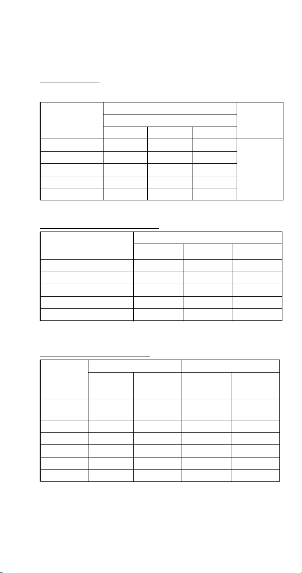
Part Number 8014793 6/18 205
S600N
All Remote Air-Cooled Condenser Models
Characteristics may vary depending on operating conditions.
CYCLE TIMES
Freeze Time + Harvest Time = Total Cycle Time
24 HOUR ICE PRODUCTION
OPERATING PRESSURES
Air Temp.
Entering
Condenser
°F/°C
Freeze Time
Harvest
Time
1
1 Times in minutes
Water Temperature °F/°C
50/10 70/21 90/32
-20/-29 to 70/21 7.9-9.4 8.8-10.3 9.3-10.9
1-2.5
80/27 7.9-94 8.9-10.5- 9.5-11.2
90/32 8.1-9.5 8.9-10.5 9.7-11.4
100/38 8.8-10.3 9.7-11.4 10.4-12.2
110/43 9.7-11.4 10.6-12.5 11.4-13.4
Air Temp. Entering
Condenser
°F/°C
Water Temperature °F/°C
12
1 Based on average ice slab weight of 4.12 - 4.75 lb
2 Ratings with JC0895 condenser dice or half dice cubes
50/10 70/21 90/32
-20/-29 to 70/21 630 580 550
80/27 630 570 530
90/32 620 570 540
100/38 580 530 500
110/43 530 490 460
Air Temp.
Entering
Condenser
°F/°C
Freeze Cycle Harvest Cycle
Discharge
Pressure
PSIG
Suction
Pressure
PSIG
1
1 Suction pressure drops gradually throughout the freeze cycle
Discharge
Pressure
PSIG
Suction
Pressure
PSIG
-20/-29 to
50/10
210-240 40-29 130-190 62-80
70/21 225-250 50-30 130-200 75-95
80/27 245-275 52-31 130-200 75-100
90/32 245-285 52-32 135-200 80-100
100/38 260-315 55-32 140-200 80-100
110/43 290-365 60-34 170-200 85-100
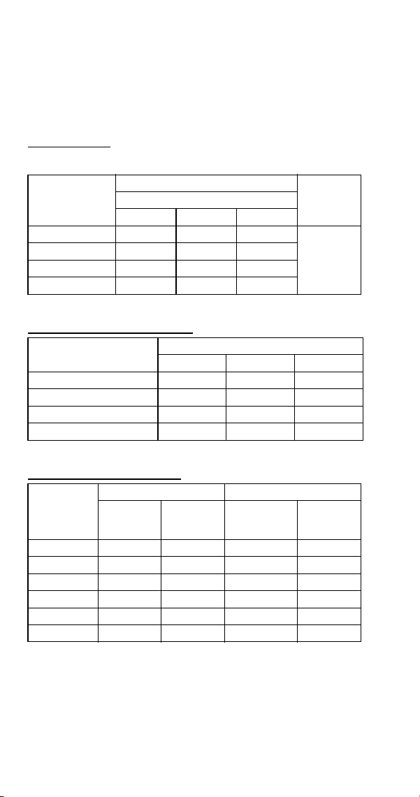
206 Part Number 8014793 6/18
S850 SERIES
S850A
All Self-Contained Air-Cooled Models Before Serial
Number 110683282
Characteristics may vary depending on operating conditions.
CYCLE TIMES
Freeze Time + Harvest Time = Total Cycle Time
24 HOUR ICE PRODUCTION
OPERATING PRESSURES
Air Temp.
Entering
Condenser
°F/°C
Freeze Time
Harvest
Time
1
1 Times in minutes
Water Temperature °F/°C
50/10 70/21 90/32
70/21 8.0-9.3 8.9-10.2 9.3-10.7
1-2.5
80/27 8.5-9.8 9.4-10.8 9.8-11.3
90/32 9.7-11.1 10.9-12.5 11.4-13.1
100/38 10.7-12.3 12.1-13.8 12.8-14.6
Air Temp. Entering
Condenser °F/°C
Water Temperature °F/°C
1
1 Based on average ice slab weight of 5.75 - 6.50 lb.
50/10 70/21 90/32
70/21 870 800 770
80/27 830 760 730
90/32 740 670 640
100/38 680 610 580
Air Temp
Entering
Condenser
°F/°C
Freeze Cycle Harvest Cycle
Discharge
Pressure
PSIG
Suction
Pressure
PSIG
1
1 Suction pressure drops gradually throughout the freeze cycle
Discharge
Pressure
PSIG
Suction
Pressure
PSIG
50/10
195-250 40-28 130-145 70-85
70/21 195-250 40-28 130-145 70-85
80/27 230-275 50-28 150-165 70-90
90/32 260-310 54-32 165-185 85-105
100/38 300-355 65-32 180-210 105-125
110/43 325-405 70-38 215-235 120-150
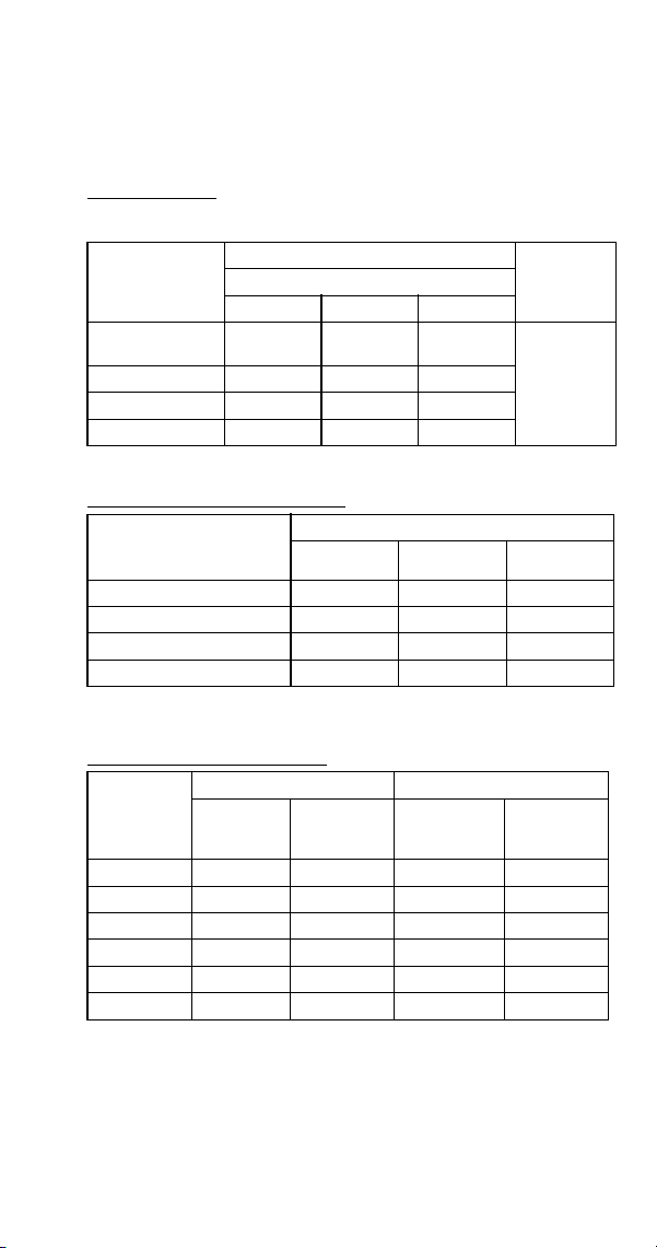
Part Number 8014793 6/18 207
SD0852A
Dice Cube, Self-Contained Air-Cooled Models After Serial
Number 110683282
Characteristics may vary depending on operating conditions.
CYCLE TIMES
Freeze Time + Harvest Time = Total Cycle Time
24 HOUR ICE PRODUCTION
OPERATING PRESSURES
Air Temp.
Entering
Condenser
°F/°C
Freeze Time
Harvest
Time
1
1 Times in minutes
Water Temperature °F/°C
50/10 70/21 90/32
35/2 to
70/21
9.0-10.4 9.8-11.2 10.5-11.2
0.75-2.0
90/32 11.3-13.0 12.0-13.7 12.9-14.8
100/38 12.9-14.8 13.7-15.7 14.6-16.7
110/43 14.9-17.0 15.8-18.0 16.5-18.8
Air Temp. Entering
Condenser
°F/°C
Water Temperature °F/°C
12
1 Based on average ice slab weight of 5.75 -6.5 lb
2 230/50/1 is approximately 12% lower than 230/60/1
50/10 70/21 90/32
35/2 to 70/21 785 735 690
90/32 645 615 575
100/38 575 545 515
110/43 505 480 460
Air Temp.
Entering
Condenser
°F/°C
Freeze Cycle Harvest Cycle
Discharge
Pressure
PSIG
Suction
Pressure
PSIG
1
1 Suction pressure drops gradually throughout the freeze cycle
Discharge
Pressure
PSIG
Suction
Pressure
PSIG
50/10 200-255 45-25 125-140 70-90
70/21 200-255 45-26 125-140 75-90
80/27 250-275 50-28 130-160 80-100
90/32 315-260 55-30 160-175 90-115
100/38 330-385 75-34 200-225 130-160
110/43 335-400 78-35 200-230 130-160
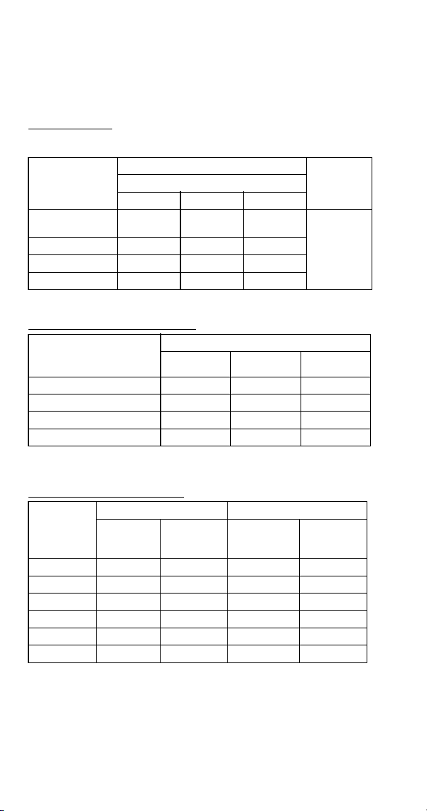
208 Part Number 8014793 6/18
SY0854A
Half Dice Cube, Self-Contained Air-Cooled Models After
Serial Number 110683282
Characteristics may vary depending on operating conditions.
CYCLE TIMES
Freeze Time + Harvest Time = Total Cycle Time
24 HOUR ICE PRODUCTION
OPERATING PRESSURES
Air Temp.
Entering
Condenser
°F/°C
Freeze Time
Harvest
Time
1
1 Times in minutes
Water Temperature °F/°C
50/10 70/21 90/32
35/2 to
70/21
7.3-8.5 8.0-9.3 8.9-10.2
0.75-2.0
90/32 9.4-10.8 9.9-11.4 11.2-12.9
100/38 10.8-12.4 11.7-13.5 12.9-14.8
110/43 12.7-14.5 13.7-15.7 14.9-17.0
Air Temp. Entering
Condenser
°F/°C
Water Temperature °F/°C
12
1 Based on average ice slab weight of 5.75 -6.5 lb
2 230/50/1 is approximately 12% lower than 230/60/1
50/10 70/21 90/32
35/2 to 70/21 940 870 800
90/32 760 725 650
100/38 675 625 575
110/43 585 545 505
Air Temp.
Entering
Condenser
°F/°C
Freeze Cycle Harvest Cycle
Discharge
Pressure
PSIG
Suction
Pressure
PSIG
1
1 Suction pressure drops gradually throughout the freeze cycle
Discharge
Pressure
PSIG
Suction
Pressure
PSIG
50/10 200-255 45-25 125-140 70-90
70/21 200-255 45-26 125-140 75-90
80/27 250-275 50-28 130-160 80-100
90/32 315-260 55-30 160-175 90-115
100/38 330-385 75-34 200-225 130-160
110/43 335-400 78-35 200-230 130-160

Part Number 8014793 6/18 209
S850W
All Self-Contained Water-Cooled Models Before Serial
Number 110683282
Characteristics may vary depending on operating conditions.
CYCLE TIMES
Freeze Time + Harvest Time = Total Cycle Time
24 HOUR ICE PRODUCTION
CONDENSER WATER CONSUMPTION
OPERATING PRESSURES
Air Temp.
Around Ice
Machine °F/°C
Freeze Time
Harvest
Time
1
1 Times in minutes
Water Temperature °F/°C
50/10 70/21 90/32
70/21 7.9-9.1 8.7-10.1 9.8-11.3
1-2.5
80/27 8.0-9.3 8.9-10.2 10.0-11.5
90/32 8.1-9.4 9.0-10.3 10.2-11.7
100/38 8.2-9.5 9.1-10.5 10.3-11.9
Air Temp. Around Ice
Machine °F/°C
Water Temperature °F/°C
1
1 Based on average ice slab weight of 5.75 - 6.50 lb.
50/10 70/21 90/32
70/21 880 810 730
80/27 870 800 720
90/32 860 790 710
100/38 850 780 700
Air Temp. Around Ice
Machine 90°F/32°C
Water Temperature °F/°C
1
1 Water regulating valve set to maintain 240 PSIG discharge pressure
50/10 70/21 90/32
Gal/24 hours 690 1420 5200
Air Temp.
Around Ice
Machine
°F/°C
Freeze Cycle Harvest Cycle
Discharge
Pressure
PSIG
Suction
Pressure
PSIG
1
1 Suction pressure drops gradually throughout the freeze cycle
Discharge
Pressure
PSIG
Suction
Pressure
PSIG
50/10
235-245 46-28 150-160 75-90
70/21 235-245 46-28 150-160 75-90
80/27 235-245 50-30 155-175 80-95
90/32 235-270 60-30 155-185 85-105
100/38 240-275 60-30 165-185 90-110
110/43 245-280 60-30 175-190 95-115
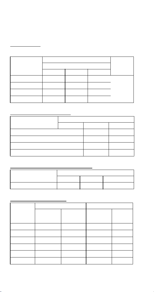
210 Part Number 8014793 6/18
SD0853W
Dice Cube, Self-Contained Water-Cooled Models After
Serial Number 110683282
Characteristics may vary depending on operating conditions.
CYCLE TIMES
Freeze Time + Harvest Time = Total Cycle Time
24 HOUR ICE PRODUCTION
CONDENSER WATER CONSUMPTION
OPERATING PRESSURES
Air Temp.
Around Ice
Machine °F/°C
Freeze Time
Harvest
Time
1
1 Times in minutes
Water Temperature °F/°C
50/10 70/21 90/32
70/21
8.4-9.7 9.5-10.9 10.7-12.3
1-2.5
80/27
9.1-10.5 9.7-11.1 11.1-12.8
90/32
9.5-10.9 10.3-11.9 11.3-13.0
100/38
9.8-11.3 10.7-12.3 11.5-13.2
Air Temp. Around Ice
Machine °F/°C
Water Temperature °F/°C
1
1 Based on average ice slab weight of 5.75 - 6.50 lb.
50/10 70/21 90/32
70/21
835 755 680
80/27
780 740 655
90/32
755 700 645
100/38
730 680 635
Air Temp. Around Ice
Machine 90°F/32°C
Water Temperature °F/°C
1
1 Water regulating valve set to maintain 230 PSIG discharge pressure
50/10 70/21 90/32
Gal/24 hours
580 1150 4200
Air Temp.
Around Ice
Machine
°F/°C
Freeze Cycle Harvest Cycle
Discharge
Pressure
PSIG
Suction
Pressure
PSIG
1
1 Suction pressure drops gradually throughout the freeze cycle
Discharge
Pressure
PSIG
Suction
Pressure
PSIG
50/10
235-225 45-30 140-160 70-85
70/21
235-225 60-30 140-160 70-85
80/27
235-225 65-30 140-160 70-85
90/32
250-230 65-30 140-160 70-90
100/38
255-240 70-33 140-160 75-95
110/43
260-240 70-34 140-160 75-95
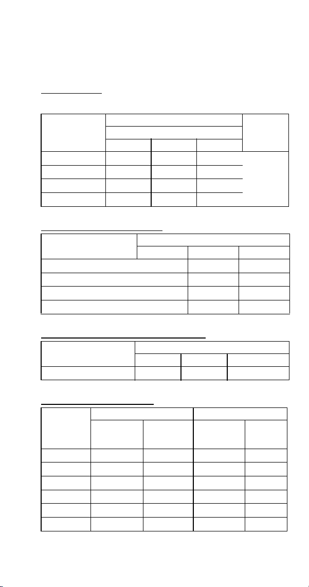
Part Number 8014793 6/18 211
SY0855W
Half Dice Cube, Self-Contained Water-Cooled Models
After Serial Number 110683282
Characteristics may vary depending on operating conditions.
CYCLE TIMES
Freeze Time + Harvest Time = Total Cycle Time
24 HOUR ICE PRODUCTION
CONDENSER WATER CONSUMPTION
OPERATING PRESSURES
Air Temp.
Around Ice
Machine °F/°C
Freeze Time
Harvest
Time
1
1 Times in minutes
Water Temperature °F/°C
50/10 70/21 90/32
70/21
8.0-9.2 8.9-10.2 10.0-11.5
1-2.5
80/27
8.2-9.4 8.7-10.1 10.2-11.7
90/32
8.3-9.6 9.2-10.6 10.2-11.8
100/38
8.4-9.7 9.3-10.7 10.3-11.9
Air Temp. Around Ice
Machine °F/°C
Water Temperature °F/°C
1
1 Based on average ice slab weight of 5.75 - 6.50 lb.
50/10 70/21 90/32
70/21
875 800 720
80/27
855 810 710
90/32
845 775 705
100/38
835 765 700
Air Temp. Around Ice
Machine 90°F/32°C
Water Temperature °F/°C
1
1 Water regulating valve set to maintain 230 PSIG discharge pressure
50/10 70/21 90/32
Gal/24 hours
580 1150 4200
Air Temp.
Around Ice
Machine
°F/°C
Freeze Cycle Harvest Cycle
Discharge
Pressure
PSIG
Suction
Pressure
PSIG
1
1 Suction pressure drops gradually throughout the freeze cycle
Discharge
Pressure
PSIG
Suction
Pressure
PSIG
50/10
235-225 45-30 140-160 70-85
70/21
235-225 60-30 140-160 70-85
80/27
235-225 65-30 140-160 70-85
90/32
250-230 65-30 140-160 70-90
100/38
255-240 70-33 140-160 75-95
110/43
260-240 70-34 140-160 75-95

212 Part Number 8014793 6/18
S850N Remote Air-cooled Condenser
All Remote Condenser Air-Cooled Before Serial Number
110682385
Characteristics may vary depending on operating conditions.
CYCLE TIMES
Freeze Time + Harvest Time = Total Cycle Time
24 HOUR ICE PRODUCTION
OPERATING PRESSURES
Air Temp.
Entering
Condenser
°F/°C
Freeze Time
Harvest
Time
1
1 Times in minutes
Water Temperature °F/°C
50/10 70/21 90/32
-20/-29 to 70/21 8.6-9.9 9.1-10.5 9.7-11.1
1-2.5
80/27 8.9-10.2 9.5-11.0 10.0-11.5
90/32 9.1-10.5 9.8-11.3 11.3-11.9
100/38 9.8-11.3 10.7-12.3 11.2-12.9
110/43 10.9-12.5 11.9-13.6 12.5-14.4
Air Temp. Entering
Condenser
°F/°C
Water Temperature °F/°C
12
1 Based on average ice slab weight of 5.75 -6.50 lb
2 Ratings with JC0895 condenser
50/10 70/21 90/32
-20/-29 to 70/21 820 780 740
80/27 800 750 720
90/32 780 730 700
100/38 730 680 650
110/43 670 620 590
Air Temp.
Entering
Condenser
°F/°C
Freeze Cycle Harvest Cycle
Discharge
Pressure
PSIG
Suction
Pressure
PSIG
1
1 Suction pressure drops gradually throughout the freeze cycle
Discharge
Pressure
PSIG
Suction
Pressure
PSIG
-20/-29 to
50/10
220-250 50-30 100-160 70-90
70/21 220-260 50-30 100-160 70-90
80/27 240-265 50-30 100-160 75-90
90/32 250-280 52-30 100-160 75-95
100/38 280-320 56-30 110-165 75-95
110/43 310-365 62-31 125-170 80-100
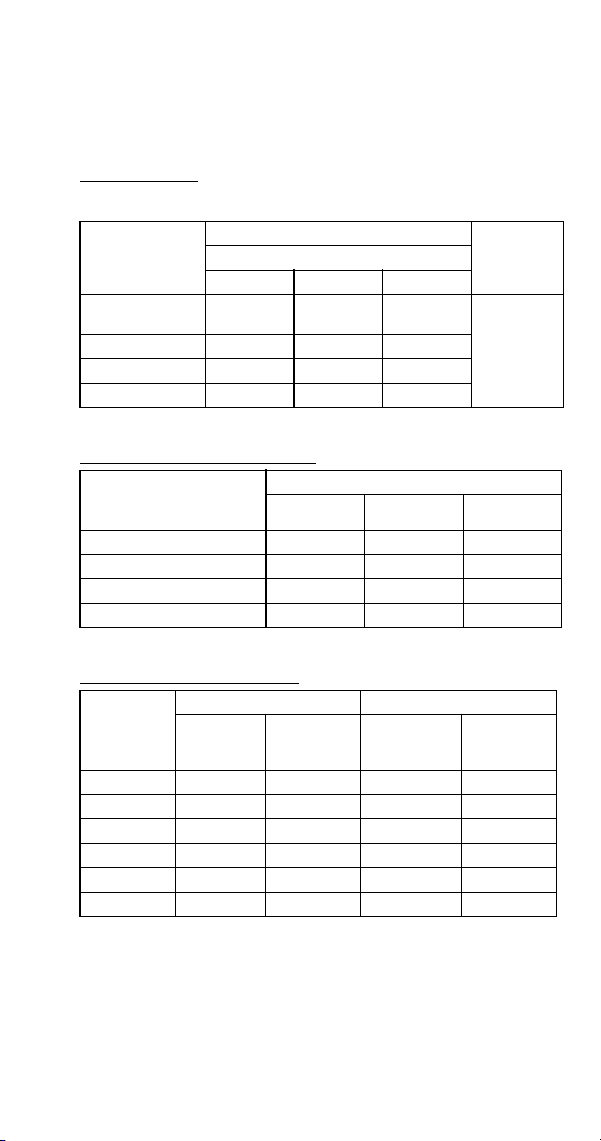
Part Number 8014793 6/18 213
SD0892N
Dice Cube, Remote Condenser Air-Cooled After Serial
Number 110682385
Characteristics may vary depending on operating conditions.
CYCLE TIMES
Freeze Time + Harvest Time = Total Cycle Time
24 HOUR ICE PRODUCTION
OPERATING PRESSURES
Air Temp.
Entering
Condenser
°F/°C
Freeze Time
Harvest
Time
1
1 Times in minutes
Water Temperature °F/°C
50/10 70/21 90/32
-20/-29 to
70/21
9.5-11.0 10.3-11.9 11.3-13.0
0.75-2.0
90/32 10.7-12.3 11.3-13.0 12.7-14.5
100/38 11.3-13.0 12.3-14.1 13.3-15.2
110/43 12.1-13.8 13.0-14.9 14.1-16.2
Air Temp. Entering
Condenser
°F/°C
Water Temperature °F/°C
1
1 Based on average ice slab weight of 5.75 -6.5 lb
50/10 70/21 90/32
-20/-29 to 70/21 750 700 645
90/32 680 645 585
100/38 645 600 560
110/43 610 570 530
Air Temp.
Entering
Condenser
°F/°C
Freeze Cycle Harvest Cycle
Discharge
Pressure
PSIG
Suction
Pressure
PSIG
1
1 Suction pressure drops gradually throughout the freeze cycle
Discharge
Pressure
PSIG
Suction
Pressure
PSIG
50/10 200-220 40-21 140-160 70-85
70/21 225-250 50-30 140-160 70-90
80/27 250-265 55-31 140-160 70-95
90/32 260-295 60-32 140-160 70-95
100/38 310-375 65-35 145-170 75-100
110/43 325-390 70-36 145-170 80-100
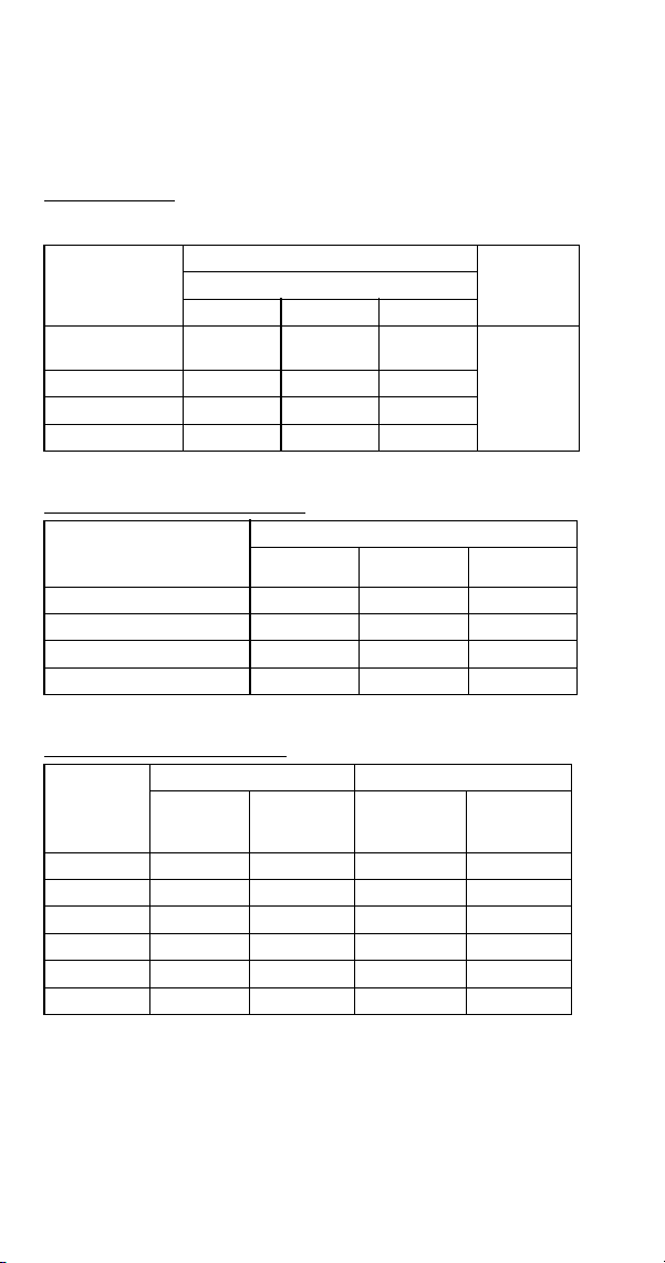
214 Part Number 8014793 6/18
SY0894N
Half Dice Cube, Remote Condenser Air-Cooled After
Serial Number 110682385
Characteristics may vary depending on operating conditions.
CYCLE TIMES
Freeze Time + Harvest Time = Total Cycle Time
24 HOUR ICE PRODUCTION
OPERATING PRESSURES
Air Temp.
Entering
Condenser
°F/°C
Freeze Time
Harvest
Time
1
1 Times in minutes
Water Temperature °F/°C
50/10 70/21 90/32
-20/-29 to
70/21
8.1-9.4 8.9-10.3 9.8-11.3
0.75-2.0
90/32 9.1-10.5 9.5-11.0 11.1-12.8
100/38 9.7-11.1 10.7-12.3 11.8-13.6
110/43 10.3-11.9 11.3-13.0 12.7-14.5
Air Temp. Entering
Condenser
°F/°C
Water Temperature °F/°C
1
1 Based on average ice slab weight of 5.75 -6.5 lb
50/10 70/21 90/32
-20/-29 to 70/21 860 795 730
90/32 780 750 655
100/38 740 680 620
110/43 700 645 585
Air Temp.
Entering
Condenser
°F/°C
Freeze Cycle Harvest Cycle
Discharge
Pressure
PSIG
Suction
Pressure
PSIG
1
1 Suction pressure drops gradually throughout the freeze cycle
Discharge
Pressure
PSIG
Suction
Pressure
PSIG
50/10 200-220 40-21 140-160 70-85
70/21 225-250 50-30 140-160 70-90
80/27 250-265 55-31 140-160 70-95
90/32 260-295 60-32 140-160 70-95
100/38 310-375 65-35 145-170 75-100
110/43 325-390 70-36 145-170 80-100
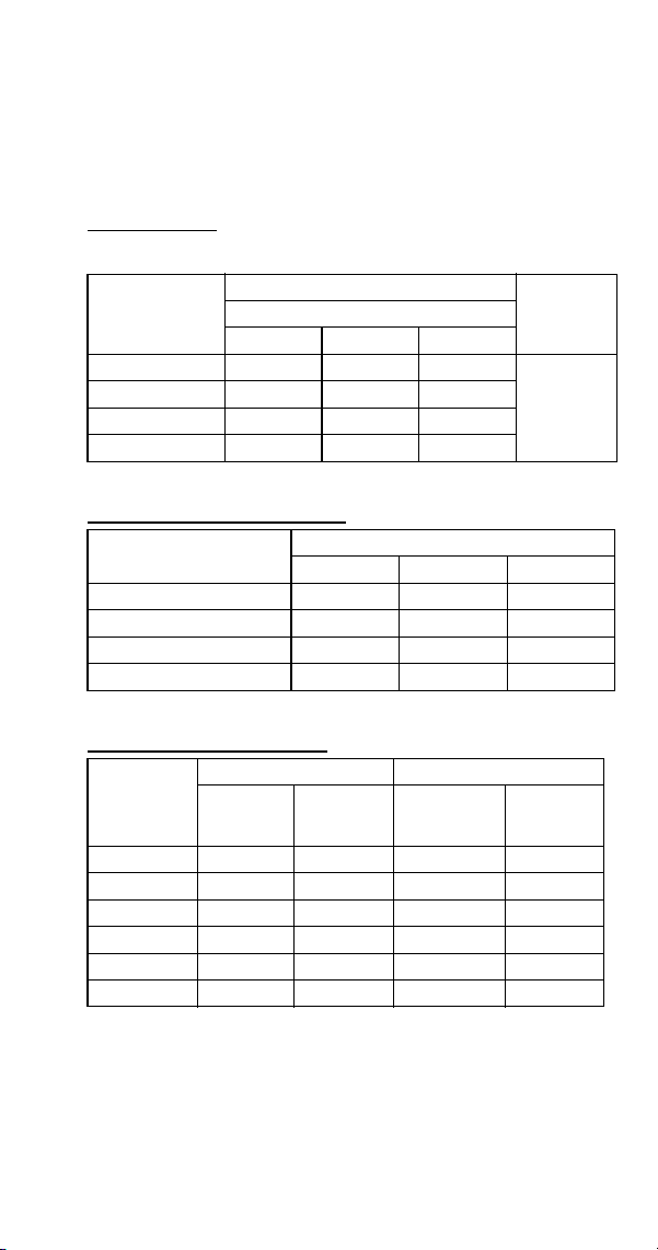
Part Number 8014793 6/18 215
S1000 SERIES
S1000A
All Self-Contained Air-cooled Before Serial Number
110697023
Characteristics may vary depending on operating conditions.
CYCLE TIMES
Freeze Time + Harvest Time = Total Cycle Time
24 HOUR ICE PRODUCTION
OPERATING PRESSURES
Air Temp.
Entering
Condenser
°F/°C
Freeze Time
Harvest
Time
1
1 Times in minutes
Water Temperature °F/°C
50/10 70/21 90/32
70/21 6.3-7.3 6.9-8.0 7.6-8.8
.75-2.0
80/27 6.9-8.1 7.6-8.8 8.4-9.6
90/32 7.8-9.0 8.5-9.8 9.4-10.8
100/38 9.3-10.7 10.2-11.7 11.0-12.7
Air Temp. Entering
Condenser °F/°C
Water Temperature °F/°C
1
1 Based on average ice slab weight of 5.75 - 6.50 lb.
50/10 70/21 90/32
70/21 1060 990 910
80/27 980 910 840
90/32 890 830 760
100/38 770 710 660
Air Temp
Entering
Condenser
°F/°C
Freeze Cycle Harvest Cycle
Discharge
Pressure
PSIG
Suction
Pressure
PSIG
1
1 Suction pressure drops gradually throughout the freeze cycle
Discharge
Pressure
PSIG
Suction
Pressure
PSIG
50/10
195-255 50-26 130-145 70-90
70/21 220-275 50-26 130-145 70-90
80/27 235-290 52-28 150-165 75-95
90/32 265-330 58-28 165-185 85-110
100/38 300-360 60-31 180-210 95-120
110/43 330-415 66-32 215-235 115-145
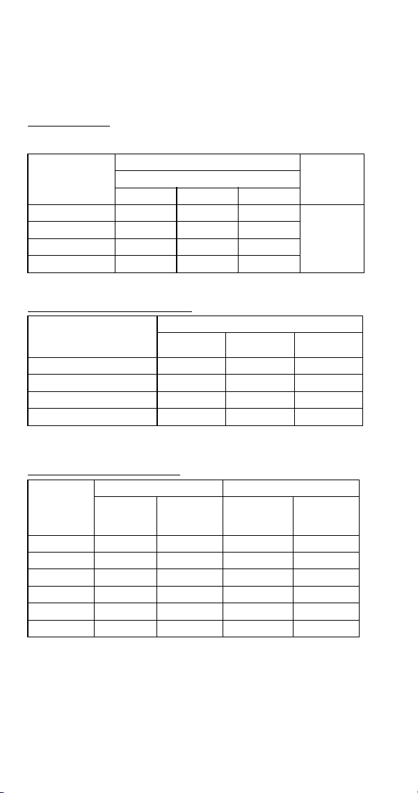
216 Part Number 8014793 6/18
SD1002A
Dice Cube, Self-Contained Air-cooled After Serial
Number 110697023
Characteristics may vary depending on operating conditions.
CYCLE TIMES
Freeze Time + Harvest Time = Total Cycle Time
24 HOUR ICE PRODUCTION
OPERATING PRESSURES
Air Temp.
Entering
Condenser
°F/°C
Freeze Time
Harvest
Time
1
1 Times in minutes
Water Temperature °F/°C
50/10 70/21 90/32
70/21 6.4-7.4 7.0-8.1 7.8-9.0
0.75-2.0
90/32 7.9-9.1 8.4-9.6 9.6-11.1
100/38 8.9-10.2 9.7-11.1 10.7-12.3
110/43 10.2-11.7 11.0-12.7 12.0-13.7
Air Temp. Entering
Condenser
°F/°C
Water Temperature °F/°C
12
1 Based on average ice slab weight of 5.75 -6.5 lb
2 230/50/1 is approximately 12% lower than 230/60/1
50/10 70/21 90/32
70/21 1050 970 890
90/32 880 840 745
100/38 800 740 680
110/43 710 660 615
Air Temp.
Entering
Condenser
°F/°C
Freeze Cycle Harvest Cycle
Discharge
Pressure
PSIG
Suction
Pressure
PSIG
1
1 Suction pressure drops gradually throughout the freeze cycle
Discharge
Pressure
PSIG
Suction
Pressure
PSIG
50/10 195-255 45-26 130-145 70-90
70/21 220-275 50-27 130-145 70-90
80/27 235-290 50-28 150-165 75-95
90/32 265-330 55-30 165-185 85-110
100/38 300-360 60-35 180-210 95-120
110/43 330-415 60-37 215-235 115-145

Part Number 8014793 6/18 217
SY1004A
Half Dice Cube, Self-Contained Air-cooled After Serial
Number 110697023
Characteristics may vary depending on operating conditions.
CYCLE TIMES
Freeze Time + Harvest Time = Total Cycle Time
24 HOUR ICE PRODUCTION
OPERATING PRESSURES
Air Temp.
Entering
Condenser
°F/°C
Freeze Time
Harvest
Time
1
1 Times in minutes
Water Temperature °F/°C
50/10 70/21 90/32
35/2 to
70/21
6.4-7.4 7.0-8.1 7.8-9.0
0.75-2.0
90/32 7.9-9.1 8.4-9.6 9.6-11.1
100/38 8.9-10.2 9.7-11.1 10.7-12.3
110/43 10.2-11.7 11.0-12.7 12.0-13.7
Air Temp. Entering
Condenser
°F/°C
Water Temperature °F/°C
12
1 Based on average ice slab weight of 5.75 -6.5 lb
2 230/50/1 is approximately 12% lower than 230/60/1
50/10 70/21 90/32
35/2 to 70/21 1050 970 890
90/32 880 840 745
100/38 800 740 680
110/43 710 660 615
Air Temp.
Entering
Condenser
°F/°C
Freeze Cycle Harvest Cycle
Discharge
Pressure
PSIG
Suction
Pressure
PSIG
1
1 Suction pressure drops gradually throughout the freeze cycle
Discharge
Pressure
PSIG
Suction
Pressure
PSIG
50/10 195-255 45-26 130-145 70-90
70/21 220-275 50-27 130-145 70-90
80/27 235-290 50-28 150-165 75-95
90/32 265-330 55-30 165-185 85-110
100/38 300-360 60-35 180-210 95-120
110/43 330-415 60-37 215-235 115-145
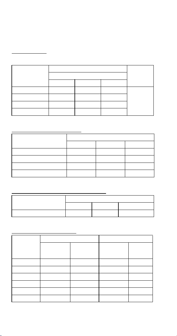
218 Part Number 8014793 6/18
S1000W
All Self-Contained Water-cooled Before Serial Number
110697023
Characteristics may vary depending on operating conditions.
CYCLE TIMES
Freeze Time + Harvest Time = Total Cycle Time
24 HOUR ICE PRODUCTION
CONDENSER WATER CONSUMPTION
OPERATING PRESSURES
Air Temp.
Around Ice
Machine °F/°C
Freeze Time
Harvest
Time
1
1 Times in minutes
Water Temperature °F/°C
50/10 70/21 90/32
70/21 6.8-7.9 7.4-8.6 8.5-9.8
.75-2.0
80/27 6.9-8.0 7.5-8.7 8.6-9.9
90/32 6.9-8.1 7.6-8.8 8.7-10.1
100/38 7.0-8.1 7.7-8.9 8.9-10.2
Air Temp. Around Ice
Machine °F/°C
Water Temperature °F/°C
1
1 Based on average ice slab weight of 5.75 - 6.50 lb.
50/10 70/21 90/32
70/21 1000 930 830
80/27 990 920 820
90/32 980 910 810
100/38 970 900 800
Air Temp. Around Ice
Machine 90°F/32°C
Water Temperature °F/°C
1
1 Water regulating valve set to maintain 240 PSIG discharge pressure
50/10 70/21 90/32
Gal/24 hours 710 1500 5100
Air Temp.
Around Ice
Machine
°F/°C
Freeze Cycle Harvest Cycle
Discharge
Pressure
PSIG
Suction
Pressure
PSIG
1
1 Suction pressure drops gradually throughout the freeze cycle
Discharge
Pressure
PSIG
Suction
Pressure
PSIG
50/10
235-245 40-24 160-175 75-90
70/21 235-245 40-25 160-175 75-90
80/27 235-250 42-26 170-185 80-95
90/32 240-270 48-28 175-205 85-105
100/38 250-280 52-28 180-210 90-110
110/43 250-285 54-28 185-215 95-115

Part Number 8014793 6/18 219
SD1003W
Dice Cube, Self-Contained Water-cooled After Serial
Number 110697023
Characteristics may vary depending on operating conditions.
CYCLE TIMES
Freeze Time + Harvest Time = Total Cycle Time
24 HOUR ICE PRODUCTION
CONDENSER WATER CONSUMPTION
OPERATING PRESSURES
Air Temp.
Around Ice
Machine °F/°C
Freeze Time
Harvest
Time
1
1 Times in minutes
Water Temperature °F/°C
50/10 70/21 90/32
70/21 6.8-7.9 7.1-8.2 8.2-9.5
0.75-2.0
90/32 7.0-8.1 7.2-8.3 8.4-9.6
100/38 7.1-8.2 7.7-8.9 8.5-9.8
110/43 7.2-8.3 7.8-9.0 8.5-9.8
Air Temp. Around Ice
Machine °F/°C
Water Temperature °F/°C
1
1 Based on average ice slab weight of 5.75 -6.5 lb
50/10 70/21 90/32
70/21 1000 965 850
90/32 975 955 840
100/38 965 900 930
110/43 955 890 825
Air Temp. Around Ice
Machine 90°F/32°C
Water Temperature °F/°C
1
1 Water regulating valve set to maintain 220 PSIG discharge pressure
50/10 70/21 90/32
Gal/24 Hours 760 1600 5500
Air Temp.
Around Ice
Machine
°F/°C
Freeze Cycle Harvest Cycle
Discharge
Pressure
PSIG
Suction
Pressure
PSIG
1
1 Suction pressure drops gradually throughout the freeze cycle
Discharge
Pressure
PSIG
Suction
Pressure
PSIG
50/10 215-225 45-22 145-170 75-85
70/21 215-225 45-23 150-170 75-90
80/27 220-225 45-24 150-175 75-95
90/32 220-230 45-25 155-175 80-100
100/38 230-250 50-26 160-195 80-110
110/43 240-260 50-27 170-200 80-115

220 Part Number 8014793 6/18
SY1005W
Half Dice Cube, Self-Contained Water-cooled After Serial
Number 110697023
Characteristics may vary depending on operating conditions.
CYCLE TIMES
Freeze Time + Harvest Time = Total Cycle Time
24 HOUR ICE PRODUCTION
CONDENSER WATER CONSUMPTION
OPERATING PRESSURES
Air Temp.
Around Ice
Machine °F/°C
Freeze Time
Harvest
Time
1
1 Times in minutes
Water Temperature °F/°C
50/10 70/21 90/32
70/21 6.2-7.2 7.0-8.1 8.0-9.3
0.75-2.0
90/32 6.5-7.6 7.1-8.3 8.2-9.4
100/38 6.7-7.8 7.4-8.6 8.2-9.5
110/43 6.9-8.0 7.5-8.7 8.3-9.6
Air Temp. Around Ice
Machine °F/°C
Water Temperature °F/°C
1
1 Based on average ice slab weight of 5.75 -6.5 lb
50/10 70/21 90/32
70/21 1075 970 870
90/32 1030 960 855
100/38 1010 930 850
110/43 990 915 845
Air Temp. Around Ice
Machine 90°F/32°C
Water Temperature °F/°C
1
1 Water regulating valve set to maintain 220 PSIG discharge pressure
50/10 70/21 90/32
Gal/24 Hours 760 1600 5500
Air Temp.
Around Ice
Machine
°F/°C
Freeze Cycle Harvest Cycle
Discharge
Pressure
PSIG
Suction
Pressure
PSIG
1
1 Suction pressure drops gradually throughout the freeze cycle
Discharge
Pressure
PSIG
Suction
Pressure
PSIG
50/10 215-225 45-22 145-170 75-85
70/21 215-225 45-23 150-170 75-90
80/27 220-225 45-24 150-175 75-95
90/32 220-230 45-25 155-175 80-100
100/38 230-250 50-26 160-195 80-110
110/43 240-260 50-27 170-200 80-115
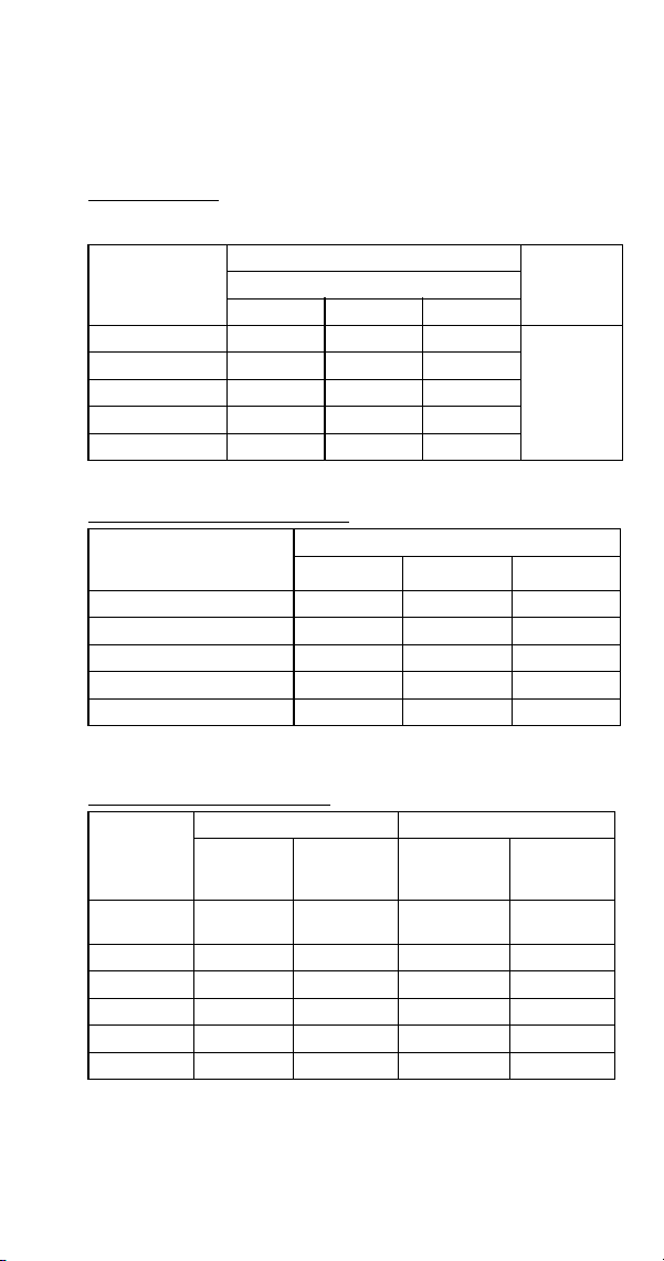
Part Number 8014793 6/18 221
S1000N
All Remote Condenser Air-cooled Before Serial Number
110697023
Characteristics may vary depending on operating conditions.
CYCLE TIMES
Freeze Time + Harvest Time = Total Cycle Time
24 HOUR ICE PRODUCTION
OPERATING PRESSURES
Air Temp.
Entering
Condenser
°F/°C
Freeze Time
Harvest
Time
1
1 Times in minutes
Water Temperature °F/°C
50/10 70/21 90/32
-20/-29 to 70/21 7.1-8.3 7.6-8.8 8.4-9.6
.75-2.0
80/27 7.5-8.7 8.0-9.3 8.9-10.2
90/32 7.7-8.9 8.2-9.5 9.1-10.5
100/38 8.1-9.4 8.7-10.1 9.7-11.1
110/43 8.7-10.1 9.4-10.8 10.7-12.3
Air Temp. Entering
Condenser
°F/°C
Water Temperature °F/°C
12
1 Based on average ice slab weight of 5.75 - 6.50 lb
2 Ratings with JC0895 condenser
50/10 70/21 90/32
-20/-29 to 70/21 960 910 840
80/27 920 870 800
90/32 900 850 780
100/38 860 810 740
110/43 810 760 680
Air Temp.
Entering
Condenser
°F/°C
Freeze Cycle Harvest Cycle
Discharge
Pressure
PSIG
Suction
Pressure
PSIG
1
1 Suction pressure drops gradually throughout the freeze cycle
Discharge
Pressure
PSIG
Suction
Pressure
PSIG
-20/-29 to
50/10
220-255 40-26 100-170 65-90
70/21 245-260 40-27 100-170 65-90
80/27 245-285 42-28 100-170 65-95
90/32 250-300 44-28 100-175 65-100
100/38 275-330 48-29 115-180 65-105
110/43 310-375 56-31 125-195 65-105

222 Part Number 8014793 6/18
SD1092N
Dice Cube, Remote Condenser Air-cooled After Serial
Number 110697023
Characteristics may vary depending on operating conditions.
CYCLE TIMES
Freeze Time + Harvest Time = Total Cycle Time
24 HOUR ICE PRODUCTION
OPERATING PRESSURES
Air Temp.
Entering
Condenser
°F/°C
Freeze Time
Harvest
Time
1
1 Times in minutes
Water Temperature °F/°C
50/10 70/21 90/32
70/21 6.5-7.6 7.1-8.3 7.9-9.1
0.75-2.0
90/32 7.5-8.7 8.0-9.3 9.1-10.5
100/38 8.1-9.3 8.9-10.2 9.8-11.3
110/43 8.7-10.1 9.6-11.1 10.8-12.4
Air Temp. Entering
Condenser
°F/°C
Water Temperature °F/°C
1
1 Based on average ice slab weight of 5.75 -6.5 lb
50/10 70/21 90/32
70/21 1030 960 885
90/32 920 870 780
100/38 865 800 730
110/43 810 745 675
Air Temp.
Entering
Condenser
°F/°C
Freeze Cycle Harvest Cycle
Discharge
Pressure
PSIG
Suction
Pressure
PSIG
1
1 Suction pressure drops gradually throughout the freeze cycle
Discharge
Pressure
PSIG
Suction
Pressure
PSIG
50/10 200-220 35-22 100-165 70-85
70/21 220-260 40-24 100-170 70-90
80/27 245-285 45-25 100-170 70-95
90/32 250-300 50-27 100-170 70-95
100/38 285-330 60-32 130-180 75-100
110/43 300-375 60-32 130-190 80-100
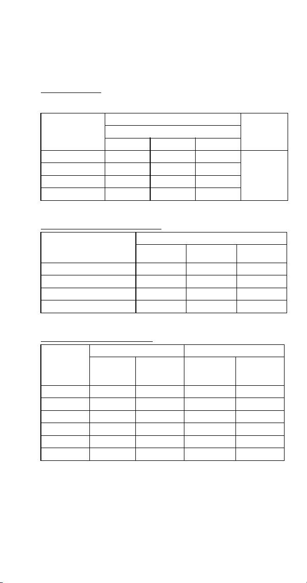
Part Number 8014793 6/18 223
SY1094N
Half Dice Cube, Remote Condenser Air-cooled After
Serial Number 110697023
Characteristics may vary depending on operating conditions.
CYCLE TIMES
Freeze Time + Harvest Time = Total Cycle Time
24 HOUR ICE PRODUCTION
OPERATING PRESSURES
Air Temp.
Entering
Condenser
°F/°C
Freeze Time
Harvest
Time
1
1 Times in minutes
Water Temperature °F/°C
50/10 70/21 90/32
70/21 6.3-7.3 6.8-7.9 7.4-8.5
0.75-2.0
90/32 7.2-8.4 7.5-8.7 8.5-9.8
100/38 7.7-8.9 8.4-9.6 9.2-10.6
110/43 8.3-9.6 9.0-10.4 9.9-11.4
Air Temp. Entering
Condenser
°F/°C
Water Temperature °F/°C
1
1 Based on average ice slab weight of 5.75 -6.5 lb
50/10 70/21 90/32
70/21 1060 1000 935
90/32 950 920 830
100/38 900 840 775
110/43 845 785 725
Air Temp.
Entering
Condenser
°F/°C
Freeze Cycle Harvest Cycle
Discharge
Pressure
PSIG
Suction
Pressure
PSIG
1
1 Suction pressure drops gradually throughout the freeze cycle
Discharge
Pressure
PSIG
Suction
Pressure
PSIG
50/10 200-220 35-22 100-165 70-85
70/21 220-260 40-24 100-170 70-90
80/27 245-285 45-25 100-170 70-95
90/32 250-300 50-27 100-170 70-95
100/38 285-330 60-32 130-180 75-100
110/43 300-375 60-32 130-190 80-100
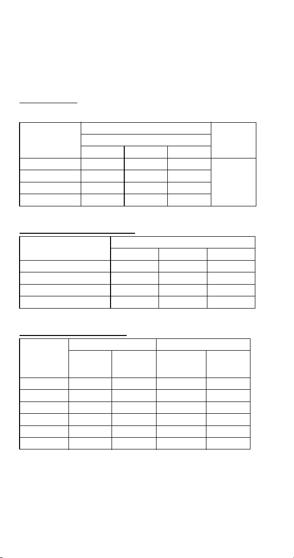
224 Part Number 8014793 6/18
S1200 SERIES
S1200A
All Self-Contained Air-cooled Before Serial Number
110697023
Characteristics may vary depending on operating conditions.
CYCLE TIMES
Freeze Time + Harvest Time = Total Cycle Time
24 HOUR ICE PRODUCTION
OPERATING PRESSURES
Air Temp.
Entering
Condenser
°F/°C
Freeze Time
Harvest
Time
1
1 Times in minutes
Water Temperature °F/°C
50/10 70/21 90/32
70/21 7.3-8.2 8.3-9.3 8.8-9.8
1-2.5
80/27 7.6-8.5 8.6-9.6 9.2-10.3
90/32 8.4-9.4 9.2-10.3 10.1-11.3
100/38 9.5-10.6 10.5-11.7 11.4-12.6
Air Temp. Entering
Condenser °F/°C
Water Temperature °F/°C
1
1 Based on average ice slab weight of 7.5 - 8.25 lb.
50/10 70/21 90/32
70/21 1230 1100 1050
80/27 1190 1070 1010
90/32 1090 1010 930
100/38 980 900 840
Air Temp
Entering
Condenser
°F/°C
Freeze Cycle Harvest Cycle
Discharge
Pressure
PSIG
Suction
Pressure
PSIG
1
1 Suction pressure drops gradually throughout the freeze cycle
Discharge
Pressure
PSIG
Suction
Pressure
PSIG
50/10 195-255 36-23 135-155 65-85
70/21 220-275 38-24 140-180 70-90
80/27 240-300 38-25 155-180 75-95
90/32 265-340 38-26 175-195 85-100
100/38 310-390 40-27 200-215 95-110
110/43 340-430 42-29 225-240 115-130
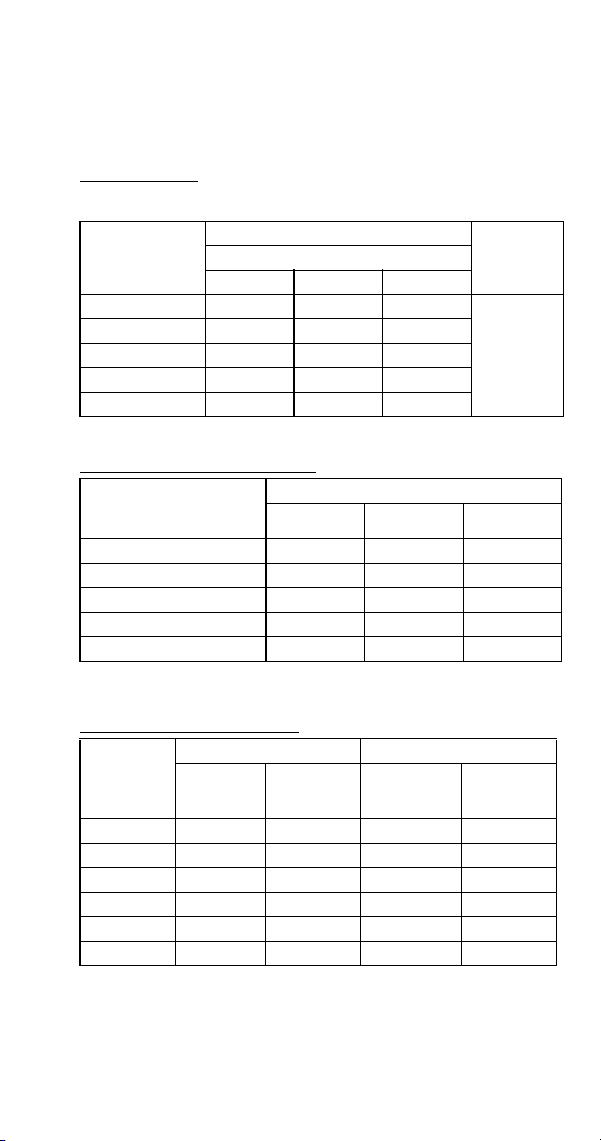
Part Number 8014793 6/18 225
SD1202A
Dice Cube, Self-Contained Air-cooled After Serial
Number 110697023
Characteristics may vary depending on operating conditions.
CYCLE TIMES
Freeze Time + Harvest Time = Total Cycle Time
24 HOUR ICE PRODUCTION
OPERATING PRESSURES
Air Temp.
Entering
Condenser
°F/°C
Freeze Time
Harvest
Time
1
1 Times in minutes
Water Temperature °F/°C
50/10 70/21 90/32
70/21 8.3-9.3 8.9-10.0 9.7-10.8
0.75-2.0
80/27 9.2-10.3 9.9-11.0 10.6-11.8
90/32 10.2-11.3 10.6-11.8 11.8-13.2
100/38 11.4-12.6 12.3-13.6 13.3-14.8
110/43 12.9-14.3 13.9-15.5 15.1-16.8
Air Temp. Entering
Condenser
°F/°C
Water Temperature °F/°C
12
1 Based on average ice slab weight of 7.5 - 8.25 lb
2 230/50/1 is approximately 12% lower than 230/60/1
50/10 70/21 90/32
70/21 1100 1035 965
80/27 1010 950 890
90/32 925 890 810
100/38 840 785 730
110/43 750 700 650
Air Temp.
Entering
Condenser
°F/°C
Freeze Cycle Harvest Cycle
Discharge
Pressure
PSIG
Suction
Pressure
PSIG
1
1 Suction pressure drops gradually throughout the freeze cycle
Discharge
Pressure
PSIG
Suction
Pressure
PSIG
50/10 195-255 40-23 135-155 65-85
70/21 220-280 50-24 140-180 70-90
80/27 240-300 50-24 155-180 75-95
90/32 265-340 55-25 175-195 85-100
100/38 310-390 60-28 200-215 95-110
110/43 340-430 60-30 225-240 115-130
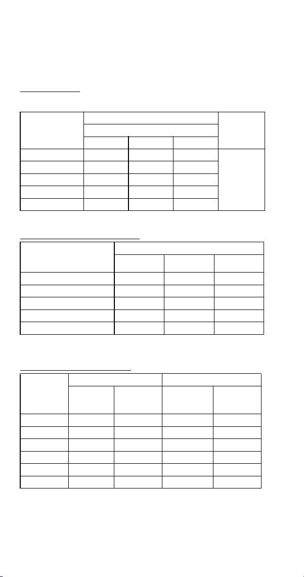
226 Part Number 8014793 6/18
SY1204A
Half Dice Cube, Self-Contained Air-cooled After Serial
Number 110697023
Characteristics may vary depending on operating conditions.
CYCLE TIMES
Freeze Time + Harvest Time = Total Cycle Time
24 HOUR ICE PRODUCTION
OPERATING PRESSURES
Air Temp.
Entering
Condenser
°F/°C
Freeze Time
Harvest
Time
1
1 Times in minutes
Water Temperature °F/°C
50/10 70/21 90/32
70/21 7.5-8.4 8.2-9.2 9.1-10.2
0.75-2.0
80/27 8.2-9.2 9.0-10.0 10.0-11.1
90/32 9.0-10.1 9.9-11.1 11.0-12.2
100/38 10.1-11.2 11.0-12.2 12.1-13.4
110/43 11.3-12.6 12.3-13.6 13.5-15.0
Air Temp. Entering
Condenser
°F/°C
Water Temperature °F/°C
12
1 Based on average ice slab weight of 5.75 -6.5 lb
2 230/50/1 is approximately 12% lower than 230/60/1
50/10 70/21 90/32
70/21 1205 1110 1015
80/27 1115 1030 940
90/32 1025 945 865
100/38 935 865 795
110/43 845 785 720
Air Temp.
Entering
Condenser
°F/°C
Freeze Cycle Harvest Cycle
Discharge
Pressure
PSIG
Suction
Pressure
PSIG
1
1 Suction pressure drops gradually throughout the freeze cycle
Discharge
Pressure
PSIG
Suction
Pressure
PSIG
50/10 195-255 40-23 135-155 65-85
70/21 220-280 50-24 140-180 70-90
80/27 240-300 50-24 155-180 75-95
90/32 265-340 55-25 175-195 85-100
100/38 310-390 60-28 200-215 95-110
110/43 340-430 60-30 225-240 115-130
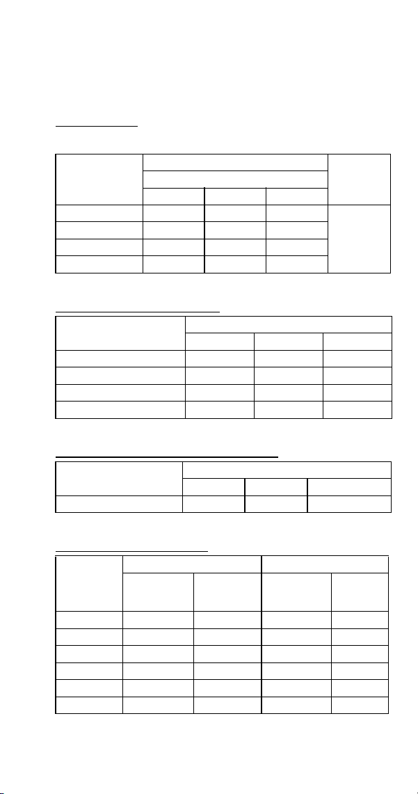
Part Number 8014793 6/18 227
S1200W
All Self-Contained Water-cooled Before Serial Number
110697023
Characteristics may vary depending on operating conditions.
CYCLE TIMES
Freeze Time + Harvest Time = Total Cycle Time
24 HOUR ICE PRODUCTION
CONDENSER WATER CONSUMPTION
OPERATING PRESSURES
Air Temp.
Around Ice
Machine °F/°C
Freeze Time
Harvest
Time
1
1 Times in minutes
Water Temperature °F/°C
50/10 70/21 90/32
70/21 7.1-7.9 7.8-8.7 9.1-10.1
1-2.5
80/27 7.4-8.2 7.9-8.8 9.1-10.1
90/32 7.5-8.4 8.1-9.1 9.3-10.4
100/38 7.9-8.8 8.2-9.2 9.4-10.5
Air Temp. Around Ice
Machine °F/°C
Water Temperature °F/°C
1
1 Based on average ice slab weight of 7.5 - 8.25 lb.
50/10 70/21 90/32
70/21 1260 1160 1020
80/27 1220 1150 1020
90/32 1200 1120 1000
100/38 1150 1110 990
Air Temp. Around Ice
Machine 90°F/32°C
Water Temperature °F/°C
1
1 Water regulating valve set to maintain 240 PSIG discharge pressure
50/10 70/21 90/32
Gal/100 lbs. of Ice 91 150 660
Air Temp.
Around Ice
Machine
°F/°C
Freeze Cycle Harvest Cycle
Discharge
Pressure
PSIG
Suction
Pressure
PSIG
1
1 Suction pressure drops gradually throughout the freeze cycle
Discharge
Pressure
PSIG
Suction
Pressure
PSIG
50/10
235-245 36-24 150-175 70-85
70/21 235-245 36-24 150-185 70-90
80/27 235-250 38-25 160-190 80-95
90/32 240-270 40-26 170-195 80-105
100/38 250-280 40-26 175-205 85-110
110/43 250-285 42-26 180-215 90-115
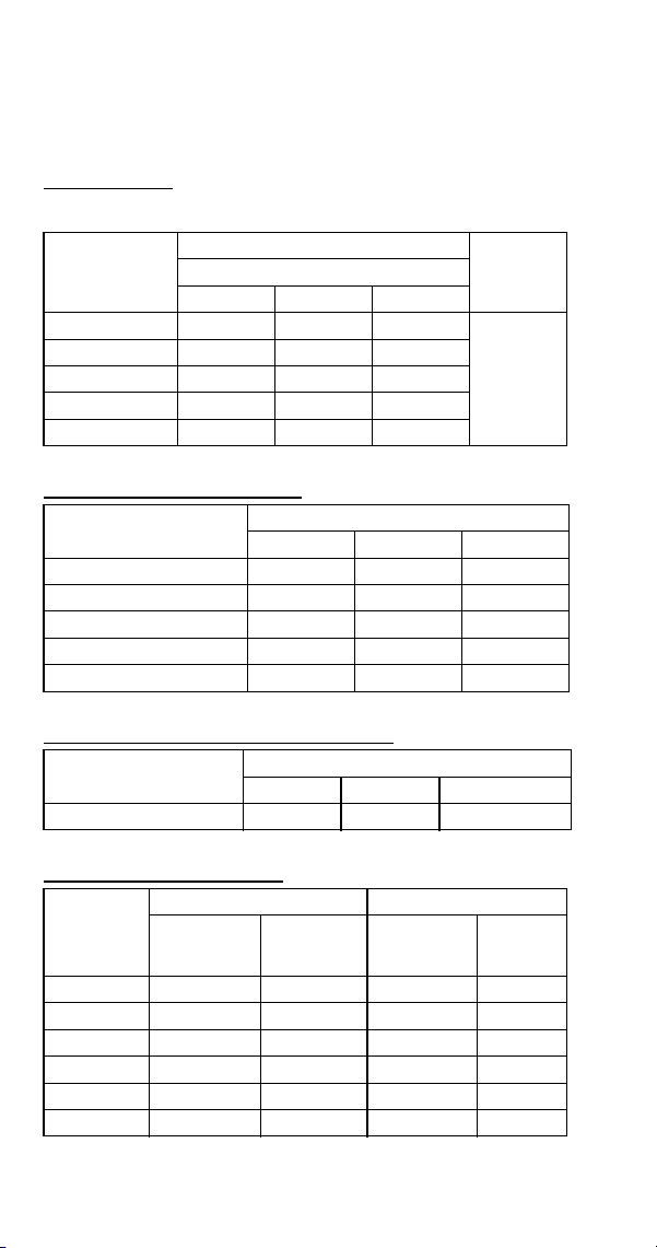
228 Part Number 8014793 6/18
SD1203W
Dice Cube, Self-Contained Water-cooled After Serial
Number 110697023
Characteristics may vary depending on operating conditions.
CYCLE TIMES
Freeze Time + Harvest Time = Total Cycle Time
24 HOUR ICE PRODUCTION
CONDENSER WATER CONSUMPTION
OPERATING PRESSURES
Air Temp.
Around Ice
Machine °F/°C
Freeze Time
Harvest
Time
1
1 Times in minutes
Water Temperature °F/°C
50/10 70/21 90/32
70/21 7.8-8.7 8.8-8.9 10.1-11.3
0.75-2.0
80/27 7.9-8.8 8.9-9.9 10.2-11.3
90/32 7.9-8.9 9.0-10.0 10.2-11.4
100/38 8.0-9.0 9.0-10.1 10.3-11.5
110/43 8.1-9.1 9.1-10.2 10.4-11.6
Air Temp. Around Ice
Machine °F/°C
Water Temperature °F/°C
1
1 Based on average ice slab weight of 5.75 -6.5 lb
50/10 70/21 90/32
70/21 1165 1050 930
80/27 1155 1040 925
90/32 1145 1030 920
100/38 1135 1025 915
110/43 1125 1015 905
Air Temp. Around Ice
Machine 90°F/32°C
Water Temperature °F/°C
1
1 Water regulating valve set to maintain 225 PSIG discharge pressure
50/10 70/21 90/32
Gal/24 Hours 770 1560 5700
Air Temp.
Around Ice
Machine
°F/°C
Freeze Cycle Harvest Cycle
Discharge
Pressure
PSIG
Suction
Pressure
PSIG
1
1 Suction pressure drops gradually throughout the freeze cycle
Discharge
Pressure
PSIG
Suction
Pressure
PSIG
50/10 215-225 40-20 150-175 70-85
70/21 215-225 42-20 150-185 70-90
80/27 235-250 44-22 160-190 80-95
90/32 240-270 45-22 170-195 80-105
100/38 240-280 50-22 175-205 85-110
110/43 240-280 50-23 180-215 85-115
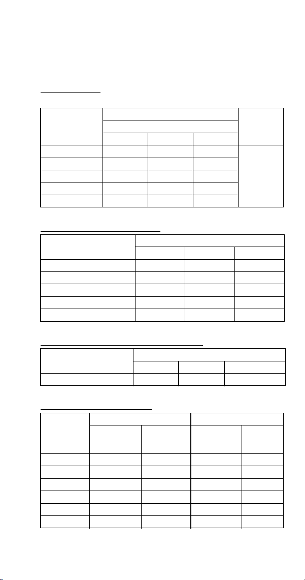
Part Number 8014793 6/18 229
SY1205W
Half Dice Cube, Self-Contained Water-cooled After Serial
Number 110697023
Characteristics may vary depending on operating conditions.
CYCLE TIMES
Freeze Time + Harvest Time = Total Cycle Time
24 HOUR ICE PRODUCTION
CONDENSER WATER CONSUMPTION
OPERATING PRESSURES
Air Temp.
Around Ice
Machine °F/°C
Freeze Time
Harvest
Time
1
1 Times in minutes
Water Temperature °F/°C
50/10 70/21 90/32
70/21 7.7-8.7 8.5-9.4 9.8-10.9
0.75-2.0
80/27 7.8-8.7 8.5-9.6 9.9-11.0
90/32 7.8-8.7 8.6-9.7 9.9-11.1
100/38 7.9-8.8 8.8-9.8 10.0-11.1
110/43 7.9-8.9 8.9-9.9 10.1-11.2
Air Temp. Around Ice
Machine °F/°C
Water Temperature °F/°C
1
1 Based on average ice slab weight of 5.75 -6.5 lb
50/10 70/21 90/32
70/21 1170 1085 955
80/27 1165 1075 950
90/32 1160 1065 945
100/38 1155 1050 940
110/43 1145 1040 935
Air Temp. Around Ice
Machine 90°F/32°C
Water Temperature °F/°C
1
1 Water regulating valve set to maintain 225 PSIG discharge pressure
50/10 70/21 90/32
Gal/24 Hours 770 1560 5700
Air Temp.
Around Ice
Machine
°F/°C
Freeze Cycle Harvest Cycle
Discharge
Pressure
PSIG
Suction
Pressure
PSIG
1
1 Suction pressure drops gradually throughout the freeze cycle
Discharge
Pressure
PSIG
Suction
Pressure
PSIG
50/10 215-225 40-20 150-175 70-85
70/21 215-225 42-20 150-185 70-90
80/27 235-250 44-22 160-190 80-95
90/32 240-270 45-22 170-195 80-105
100/38 240-280 50-22 175-205 85-110
110/43 240-280 50-23 180-215 85-115
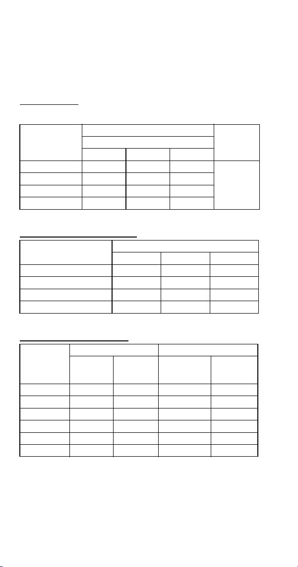
230 Part Number 8014793 6/18
S1400 SERIES
S1400 Self-contained air-cooled
All Self-Contained Air-cooled with a Manufacture Date
Before 0905 (May 2009)
Characteristics may vary depending on operating conditions.
CYCLE TIMES
Freeze Time + Harvest Time = Total Cycle Time
24 HOUR ICE PRODUCTION
OPERATING PRESSURES
Air Temp.
Entering
Condenser
°F/°C
Freeze Time
Harvest
Time
1
1 Times in minutes
Water Temperature °F/°C
50/10 70/21 90/32
70/21 8.4-9.4 9.4-10.5 10.0-11.2
1 - 2.5
80/27 8.9-9.9 9.9-11.1 10.8-12.0
90/32 10.2-11.2 10.9-12.2 11.8-13.2
100/38 11.6-12.9 12.8-14.2 13.8-15.4
Air Temp. Entering
Condenser °F/°C
Water Temperature °F/°C
1
1 Based on average ice slab weight of 10 - 11 lb.
50/10 70/21 90/32
70/21 1450 1320 1250
80/27 1390 1260 1170
90/32 1250 1160 1080
100/38 1100 1010 940
Air Temp
Entering
Condenser
°F/°C
Freeze Cycle Harvest Cycle
Discharge
Pressure
PSIG
Suction
Pressure
PSIG
1
1 Suction pressure drops gradually throughout the freeze cycle
Discharge
Pressure
PSIG
Suction
Pressure
PSIG
50/10 220-280 40-28 150-180 70-90
70/21 220-280 42-28 160-180 70-90
80/27 225-290 44-30 160-180 70-90
90/32 260-310 46-30 180-200 80-100
100/38 290-360 48-31 200-220 90-115
110/43 320-400 50-32 220-250 100-140
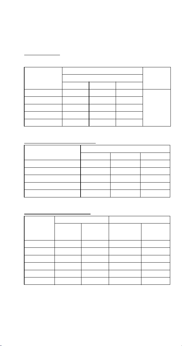
Part Number 8014793 6/18 231
SD1402A
Dice Cube, Self-Contained Air-Cooled With a
Manufacture Date of 0905 (May 2009) or Later
Characteristics may vary depending on operating conditions.
CYCLE TIMES
Freeze Time + Harvest Time = Total Cycle Time
24 HOUR ICE PRODUCTION
OPERATING PRESSURES
Air Temp.
Entering
Condenser
°F/°C
Freeze Time
Harvest
Time
1
1 Times in minutes
Water Temperature °F/°C
50/10 70/21 90/32
70/21 8.8-10.0 9.6-11.0 10.3-11.7
0.75 - 2.5
80/27 9.5-10.9 10.4-11.9 11.2-12.8
90/32 10.1-11.5 11.1-12.7 12.0-13.7
100/38 11.3-12.9 12.6-14.3 13.7-15.6
110/43 13.0-14.7 14.5-16.5 16.1-18.2
Air Temp. Entering
Condenser °F/°C
Water Temperature °F/°C
1
1 Based on average ice slab weight of 10.25 - 11.5 lb.
50/10 70/21 90/32
70/21 1440 1330 1250
80/27 1340 1240 1160
90/32 1270 1170 1090
100/38 1150 1050 970
110/43 1020 920 840
Air Temp
Entering
Condenser
°F/°C
Freeze Cycle Harvest Cycle
Discharge
Pressure
PSIG
Suction
Pressure
PSIG
1
1 Suction pressure drops gradually throughout the freeze cycle
Discharge
Pressure
PSIG
Suction
Pressure
PSIG
50/10 220-280 40-24 150-180 70-90
70/21 220-280 40-26 160-180 70-90
80/27 240-290 50-27 160-180 70-90
90/32 260-330 50-27 180-200 80-100
100/38 300-370 54-28 200-220 90-115
110/43 330-410 60-29 220-250 100-130
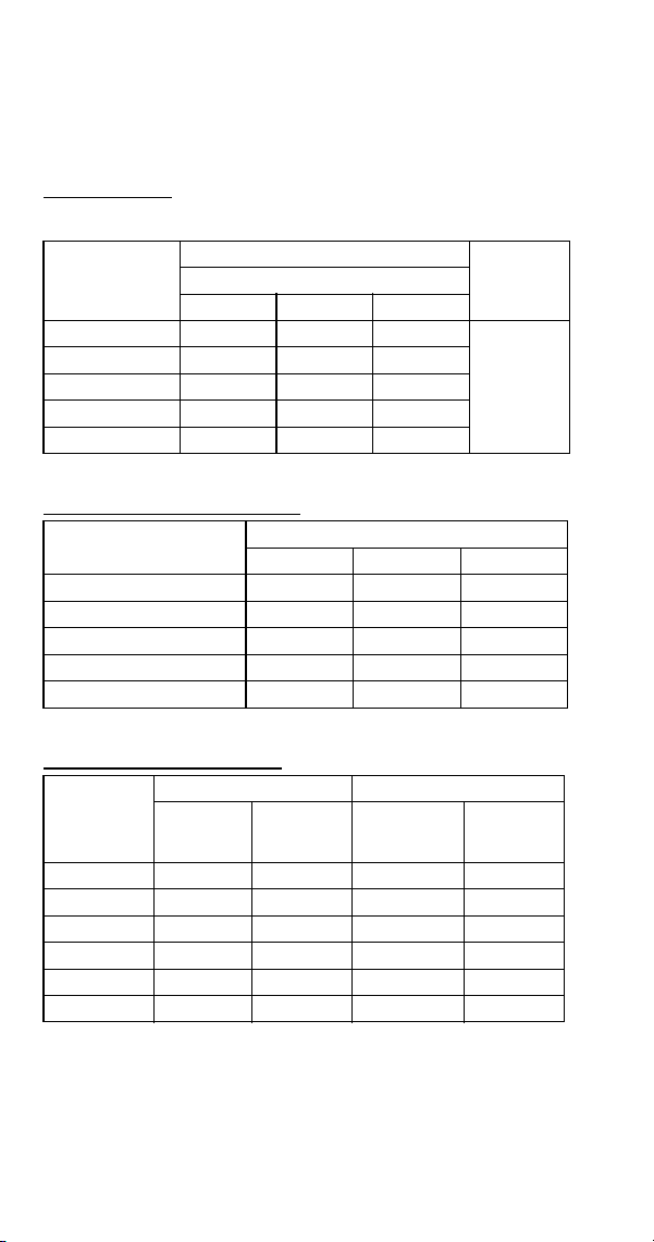
232 Part Number 8014793 6/18
SY1404A
Half Dice Cube, Self-Contained Air-Cooled With a
Manufacture Date of 0905 (May 2009) or Later
Characteristics may vary depending on operating conditions.
CYCLE TIMES
Freeze Time + Harvest Time = Total Cycle Time
24 HOUR ICE PRODUCTION
OPERATING PRESSURES
Air Temp.
Entering
Condenser
°F/°C
Freeze Time
Harvest
Time
1
1 Times in minutes
Water Temperature °F/°C
50/10 70/21 90/32
70/21 8.7-9.9 9.6-11.0 10.2-11.6
0.75 - 2.5
80/27 9.1-10.4 10.1-11.5 10.8-12.3
90/32 9.7-11.0 10.8-12.3 11.6-13.2
100/38 10.6-12.1 11.9-13.6 12.8-14.6
110/43 11.9-13.6 13.6-15.4 14.7-16.7
Air Temp. Entering
Condenser °F/°C
Water Temperature °F/°C
1
1 Based on average ice slab weight of 10.25 - 11.5 lb.
50/10 70/21 90/32
70/21 1450 1330 1260
80/27 1390 1270 1200
90/32 1320 1200 1130
100/38 1220 1100 1030
110/43 1100 980 910
Air Temp
Entering
Condenser
°F/°C
Freeze Cycle Harvest Cycle
Discharge
Pressure
PSIG
Suction
Pressure
PSIG
1
1 Suction pressure drops gradually throughout the freeze cycle
Discharge
Pressure
PSIG
Suction
Pressure
PSIG
50/10 220-280 40-24 150-180 70-90
70/21 220-280 40-26 160-180 70-90
80/27 240-290 50-27 160-180 70-90
90/32 260-330 50-27 180-200 80-100
100/38 300-370 54-28 200-220 90-115
110/43 330-410 60-29 220-250 100-130

Part Number 8014793 6/18 233
S1400 Self-contained Water-cooled
All Self-Contained Water-cooled with a Manufacture Date
Before 0711 (November 2007)
Characteristics may vary depending on operating conditions.
CYCLE TIMES
Freeze Time + Harvest Time = Total Cycle Time
24 HOUR ICE PRODUCTION
CONDENSER WATER CONSUMPTION
OPERATING PRESSURES
Air Temp.
Around Ice
Machine °F/°C
Freeze Time
Harvest
Time
1
1 Times in minutes
Water Temperature °F/°C
50/10 70/21 90/32
70/21 8.9-10.0 9.8-10.9 11.2-12.5
1 - 2.5
80/27 8.9-10.0 9.8-10.9 11.4-12.6
90/32 8.9-10.0 9.6-10.7 11.6-12.9
100/38 9.0-10.1 10.0-11.2 11.7-13.0
Air Temp. Around Ice
Machine °F/°C
Water Temperature °F/°C
1
1 Based on average ice slab weight of 10 - 11 lb.
50/10 70/21 90/32
70/21 1380 1280 1130
80/27 1380 1280 1120
90/32 1380 1300 1100
100/38 1370 1250 1090
Air Temp. Around Ice
Machine 90°F/32°C
Water Temperature °F/°C
1
1 Water regulating valve set to maintain 240 PSIG discharge pressure
50/10 70/21 90/32
Gal/100 lbs. of Ice 90 145 590
Air Temp.
Around Ice
Machine
°F/°C
Freeze Cycle Harvest Cycle
Discharge
Pressure
PSIG
Suction
Pressure
PSIG
1
1 Suction pressure drops gradually throughout the freeze cycle
Discharge
Pressure
PSIG
Suction
Pressure
PSIG
50/10 235-245 40-28 160-175 70-90
70/21 235-245 42-29 160-175 75-100
80/27 235-260 42-30 170-195 80-105
90/32 240-270 42-30 180-200 85-110
100/38 250-280 43-30 185-200 90-110
110/43 250-285 44-31 190-205 90-115
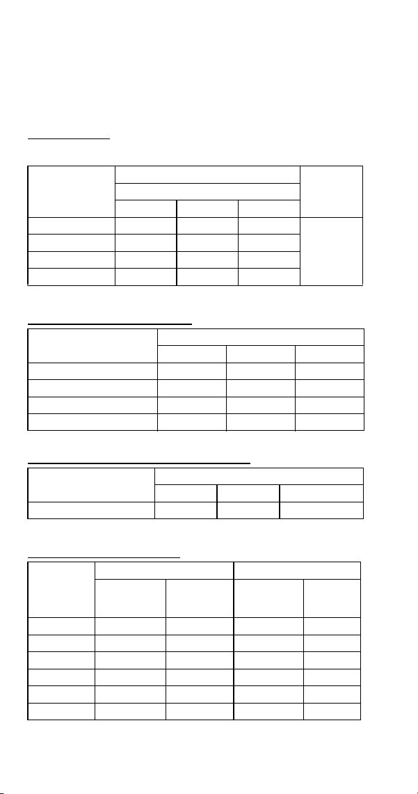
234 Part Number 8014793 6/18
SD1403W
Dice Cube, Self-Contained Water-Cooled With a
Manufacture Date From 0711 to 0905 (November 2007 to
May 2009)
Characteristics may vary depending on operating conditions.
CYCLE TIMES
Freeze Time + Harvest Time = Total Cycle Time
24 HOUR ICE PRODUCTION
CONDENSER WATER CONSUMPTION
OPERATING PRESSURES
Air Temp.
Around Ice
Machine °F/°C
Freeze Time
Harvest
Time
1
1 Times in minutes
Water Temperature °F/°C
50/10 70/21 90/32
70/21 9.0-10.0 10.0-11.2 11.3-12.6
0.75-2.0
90/32 9.4-10.5 10.4-11.6 11.8-13.1
100/38 9.6-10.7 10.7-11.9 12.0-13.3
110/43 9.8-10.9 10.9-12.1 12.2-13.6
Air Temp. Around Ice
Machine °F/°C
Water Temperature °F/°C
1
1 Based on average ice slab weight of 10 - 11 lb.
50/10 70/21 90/32
70/21 1375 1250 1125
90/32 1325 1210 1085
100/38 1300 1185 1070
110/43 1280 1165 1050
Air Temp. Around Ice
Machine 90°F/32°C
Water Temperature °F/°C
1
1 Water regulating valve set to maintain 230 PSIG discharge pressure
50/10 70/21 90/32
Gal/100 lbs. of Ice 85 140 510
Air Temp.
Around Ice
Machine
°F/°C
Freeze Cycle Harvest Cycle
Discharge
Pressure
PSIG
Suction
Pressure
PSIG
1
1 Suction pressure drops gradually throughout the freeze cycle
Discharge
Pressure
PSIG
Suction
Pressure
PSIG
50/10 225-235 40-28 160-175 70-90
70/21 225-235 42-28 160-175 75-100
80/27 230-260 42-28 170-195 80-105
90/32 240-270 42-28 180-200 85-110
100/38 250-280 43-30 185-200 90-110
110/43 250-285 44-31 190-205 90-115
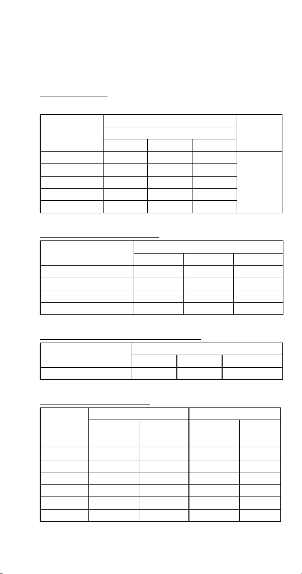
Part Number 8014793 6/18 235
SY1405W
Half Dice Cube, Self-Contained Water-Cooled With a
Manufacture Date From 0711 to 0905 (November 2007 to
May 2009)
Characteristics may vary depending on operating conditions.
CYCLE TIMES -
Freeze Time + Harvest Time = Total Cycle Time
24 HOUR ICE PRODUCTION
CONDENSER WATER CONSUMPTION
OPERATING PRESSURES
Air Temp.
Around Ice
Machine °F/°C
Freeze Time
Harvest
Time
1
1 Times in minutes
Water Temperature °F/°C
50/10 70/21 90/32
70/21 8.6-9.8 9.4-10.8 10.8-12.3
0.75-2.0
80/27 8.8-10.0 9.6-11.0 11.0-12.5
90/32 8.8-10.1 9.8-11.1 11.2-12.8
100/38 8.9-10.2 9.9-11.2 11.3-12.9
110/43 9.0-10.2 9.9-11.3 11.4-13.0
Air Temp. Around Ice
Machine °F/°C
Water Temperature °F/°C
1
1 Based on average ice slab weight of 10.25 - 11.5 lb.
50/10 70/21 90/32
70/21 1460 1350 1200
90/32 1430 1310 1160
100/38 1420 1300 1150
110/43 1410 1290 1140
Air Temp. Around Ice
Machine 90°F/32°C
Water Temperature °F/°C
1
1 Water regulating valve set to maintain 230 PSIG discharge pressure
50/10 70/21 90/32
Gal/100 lbs. of Ice 82 143 430
Air Temp.
Around Ice
Machine
°F/°C
Freeze Cycle Harvest Cycle
Discharge
Pressure
PSIG
Suction
Pressure
PSIG
1
1 Suction pressure drops gradually throughout the freeze cycle
Discharge
Pressure
PSIG
Suction
Pressure
PSIG
50/10 220-280 40-24 150-180 70-90
70/21 220-280 40-26 160-180 70-90
80/27 240-290 50-27 160-180 70-90
90/32 260-330 50-27 180-200 80-100
100/38 300-370 54-28 200-220 90-115
110/43 330-410 60-29 220-250 100-130
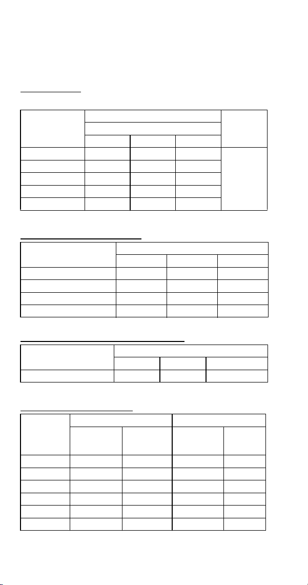
236 Part Number 8014793 6/18
SD1403W
Dice Cube, Self-Contained Water-Cooled With a
Manufacture Date of 0905 (May 2009) or Later
Characteristics may vary depending on operating conditions.
CYCLE TIMES
Freeze Time + Harvest Time = Total Cycle Time
24 HOUR ICE PRODUCTION
CONDENSER WATER CONSUMPTION
OPERATING PRESSURES
Air Temp.
Around Ice
Machine °F/°C
Freeze Time
Harvest
Time
1
1 Times in minutes
Water Temperature °F/°C
50/10 70/21 90/32
70/21 8.8-10.1 9.8-11.1 11.2-12.8
0.75-2.0
80/27 8.9-10.2 9.9-11.2 11.3-12.9
90/32 9.0-10.2 9.9-11.3 11.4-13.0
100/38 9.0-10.3 10.0-11.4 11.6-13.2
110/43 9.1-10.4 10.1-11.5 11.7-13.3
Air Temp. Around Ice
Machine °F/°C
Water Temperature °F/°C
1
1 Based on average ice slab weight of 10.25 - 11.5 lb.
50/10 70/21 90/32
70/21 1430 1310 1160
90/32 1410 1290 1140
100/38 1400 1280 1130
110/43 1390 1270 1120
Air Temp. Around Ice
Machine 90°F/32°C
Water Temperature °F/°C
1
1 Water regulating valve set to maintain 230 PSIG discharge pressure
50/10 70/21 90/32
Gal/100 lbs. of Ice 82 143 430
Air Temp.
Around Ice
Machine
°F/°C
Freeze Cycle Harvest Cycle
Discharge
Pressure
PSIG
Suction
Pressure
PSIG
1
1 Suction pressure drops gradually throughout the freeze cycle
Discharge
Pressure
PSIG
Suction
Pressure
PSIG
50/10 220-280 40-24 150-180 70-90
70/21 220-280 40-26 160-180 70-90
80/27 240-290 50-27 160-180 70-90
90/32 260-330 50-27 180-200 80-100
100/38 300-370 54-28 200-220 90-115
110/43 330-410 60-29 220-250 100-130

Part Number 8014793 6/18 237
SY1405W
Half Dice Cube, Self-Contained Water-Cooled With a
Manufacture Date of 0905 (May 2009) or Later
Characteristics may vary depending on operating conditions.
CYCLE TIMES
Freeze Time + Harvest Time = Total Cycle Time
24 HOUR ICE PRODUCTION
CONDENSER WATER CONSUMPTION
OPERATING PRESSURES
Air Temp.
Around Ice
Machine °F/°C
Freeze Time
Harvest
Time
1
1 Times in minutes
Water Temperature °F/°C
50/10 70/21 90/32
70/21 8.6-9.6 9.6-10.7 10.9-12.2
0.75-2.0
90/32 8.8-9.9 9.8-10.9 11.2-12.5
100/38 9.0-10.0 10.1-11.2 11.4-12.7
110/43 9.1-10.1 10.2-11.4 11.6-12.9
Air Temp. Around Ice
Machine °F/°C
Water Temperature °F/°C
1
1 Based on average ice slab weight of 10 - 11 lb.
50/10 70/21 90/32
70/21 1430 1300 1160
90/32 1395 1275 1130
100/38 1375 1245 1115
110/43 1360 1230 1100
Air Temp. Around Ice
Machine 90°F/32°C
Water Temperature °F/°C
1
1 Water regulating valve set to maintain 230 PSIG discharge pressure
50/10 70/21 90/32
Gal/100 lbs. of Ice 85 140 510
Air Temp.
Around Ice
Machine
°F/°C
Freeze Cycle Harvest Cycle
Discharge
Pressure
PSIG
Suction
Pressure
PSIG
1
1 Suction pressure drops gradually throughout the freeze cycle
Discharge
Pressure
PSIG
Suction
Pressure
PSIG
50/10 225-235 40-28 160-175 70-90
70/21 225-235 42-28 160-175 75-100
80/27 230-260 42-28 170-195 80-105
90/32 240-270 42-28 180-200 85-110
100/38 250-280 43-30 185-200 90-110
110/43 250-285 44-31 190-205 90-115

238 Part Number 8014793 6/18
S1400 Remote Air-cooled Condenser
All Remote Condenser Air-cooled with a Manufacture
Date Before 0905 (May 2009)
Characteristics may vary depending on operating conditions.
CYCLE TIMES
Freeze Time + Harvest Time = Total Cycle Time
24 HOUR ICE PRODUCTION
OPERATING PRESSURES
Air Temp.
Entering
Condenser
°F/°C
Freeze Time
Harvest
Time
1
1 Times in minutes
Water Temperature °F/°C
50/10 70/21 90/32
-20/-29 to 70/21 9.1-10.1 10.1-11.3 11.0-12.3
1 - 2.5
80/27 9.2-10.2 10.0-11.2 11.2-12.5
90/32 9.4-10.5 10.4-11.6 11.4-12.6
100/38 9.9-11.1 11.1-12.4 12.3-13.7
110/43 9.1-10.1 10.1-11.3 11.0-12.3
Air Temp. Entering
Condenser
°F/°C
Water Temperature °F/°C
12
1 Based on average ice slab weight of 10 - 11 lb
2 Ratings with JC1395 condenser
50/10 70/21 90/32
-20/-29 to 70/21 1360 1240 1150
80/37 1350 1250 1130
90/32 1320 1210 1120
100/38 1260 1140 1040
110/43 1360 1240 1150
Air Temp.
Entering
Condenser
°F/°C
Freeze Cycle Harvest Cycle
Discharge
Pressure
PSIG
Suction
Pressure
PSIG
1
1 Suction pressure drops gradually throughout the freeze cycle
Discharge
Pressure
PSIG
Suction
Pressure
PSIG
-20/-29 to
50/10
210-240 38-28 100-160 70-85
70/21 240-265 40-28 110-170 70-90
80/27 250-275 41-29 110-180 70-95
90/32 250-290 42-30 110-180 70-95
100/38 275-335 43-31 110-185 75-100
110/43 310-375 45-32 120-190 80-100
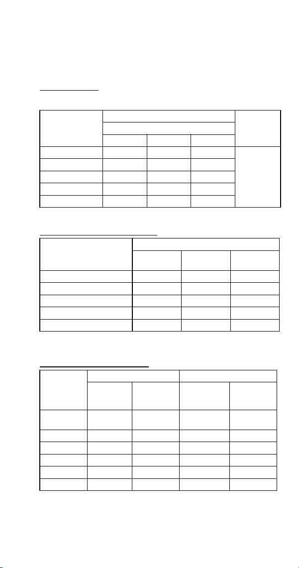
Part Number 8014793 6/18 239
SD1492N
Dice Cube, Remote Condenser Air-Cooled With a
Manufacture Date of 0905 (May 2009) or Later
Characteristics may vary depending on operating conditions.
CYCLE TIMES
Freeze Time + Harvest Time = Total Cycle Time
24 HOUR ICE PRODUCTION
OPERATING PRESSURES
Air Temp.
Entering
Condenser
°F/°C
Freeze Time
Harvest
Time
1
1 Times in minutes
Water Temperature °F/°C
50/10 70/21 90/32
70/21 9.2-10.5 10.1-11.5 10.8-12.3
0.75 - 2.5
80/27 9.4-10.7 10.3-11.7 11.0-12.5
90/32 9.6-11.0 10.7-12.2 11.4-13.0
100/38 10.4-11.9 11.7-13.3 12.6-14.3
110/43 11.2-12.8 12.7-14.4 13.7-15.6
Air Temp. Entering
Condenser
°F/°C
Water Temperature °F/°C
12
1 Based on average ice slab weight of 10.25 - 11.5 lb
2 Ratings with JC1395 condenser
50/10 70/21 90/32
70/21 1380 1270 1200
80/37 1360 1250 1180
90/32 1330 1210 1140
100/38 1240 1120 1050
110/43 1160 1040 970
Air Temp.
Entering
Condenser
°F/°C
Freeze Cycle Harvest Cycle
Discharge
Pressure
PSIG
Suction
Pressure
PSIG
1
1 Suction pressure drops gradually throughout the freeze cycle
Discharge
Pressure
PSIG
Suction
Pressure
PSIG
-20/-29 to
50/10
210-240 38-24 100-160 70-85
70/21 240-265 40-26 110-170 70-90
80/27 250-275 45-28 110-180 70-95
90/32 250-290 48-29 110-180 70-95
100/38 275-335 51-31 110-185 75-100
110/43 310-375 55-32 120-190 80-110
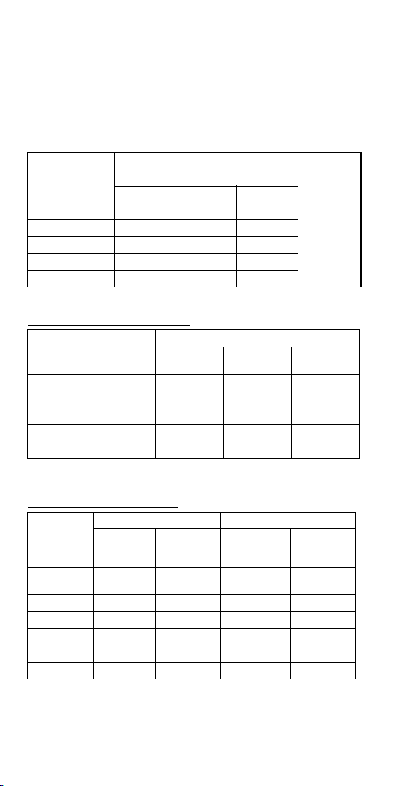
240 Part Number 8014793 6/18
SY1494N
Half Dice Cube, Remote Condenser Air-Cooled With a
Manufacture Date of 0905 (May 2009) or Later
Characteristics may vary depending on operating conditions.
CYCLE TIMES
Freeze Time + Harvest Time = Total Cycle Time
24 HOUR ICE PRODUCTION
OPERATING PRESSURES
Air Temp.
Entering
Condenser
°F/°C
Freeze Time
Harvest
Time
1
1 Times in minutes
Water Temperature °F/°C
50/10 70/21 90/32
70/21 8.8-10.1 9.7-11.0 10.6-12.1
0.75 - 2.5
80/27 9.0-10.3 9.9-11.3 10.9-12.4
90/32 9.3-10.6 10.5-12.0 11.2-12.8
100/38 9.9-11.2 11.2-12.8 12.0-13.7
110/43 10.6-12.1 12.0-13.7 13.1-14.9
Air Temp. Entering
Condenser
°F/°C
Water Temperature °F/°C
12
1 Based on average ice slab weight of 10.25 - 11.5 lb
2 Ratings with JC1395 condenser
50/10 70/21 90/32
70/21 1430 1320 1220
80/37 1400 1290 1190
90/32 1370 1230 1160
100/38 1300 1160 1090
110/43 1220 1090 1010
Air Temp.
Entering
Condenser
°F/°C
Freeze Cycle Harvest Cycle
Discharge
Pressure
PSIG
Suction
Pressure
PSIG
1
1 Suction pressure drops gradually throughout the freeze cycle
Discharge
Pressure
PSIG
Suction
Pressure
PSIG
-20/-29 to
50/10
210-240 38-24 100-160 70-85
70/21 240-265 40-26 110-170 70-90
80/27 250-275 45-28 110-180 70-95
90/32 250-290 48-29 110-180 70-95
100/38 275-335 51-31 110-185 75-100
110/43 310-375 55-32 120-190 80-110
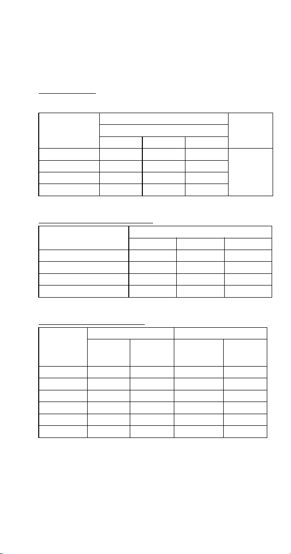
Part Number 8014793 6/18 241
S1600 SERIES
S1600A
All Self-Contained Air-cooled
Characteristics may vary depending on operating conditions.
CYCLE TIMES
Freeze Time + Harvest Time = Total Cycle Time
24 HOUR ICE PRODUCTION
OPERATING PRESSURES
Air Temp.
Entering
Condenser
°F/°C
Freeze Time
Harvest
Time
1
1 Times in minutes
Water Temperature °F/°C
50/10 70/21 90/32
70/21 9.6-10.5 10.7-11.7 11.1-12.2
1 - 2.5
80/27 10.0-11.0 11.3-12.4 12.1-13.2
90/32 11.1-12.2 12.2-13.3 12.2-13.3
100/38 12.5-13.7 13.7-15.0 15.1-16.5
Air Temp. Entering
Condenser °F/°C
Water Temperature °F/°C
1
1 Based on average ice slab weight of 13 - 14.125 lb.
50/10 70/21 90/32
70/21 1690 1540 1480
80/27 1630 1460 1380
90/32 1490 1370 1370
100/38 1340 1230 1130
Air Temp
Entering
Condenser
°F/°C
Freeze Cycle Harvest Cycle
Discharge
Pressure
PSIG
Suction
Pressure
PSIG
1
1 Suction pressure drops gradually throughout the freeze cycle
Discharge
Pressure
PSIG
Suction
Pressure
PSIG
50/10 220-280 46-27 150-165 70-90
70/21 220-280 50-28 150-165 70-90
80/27 240-300 55-32 155-175 75-95
90/32 270-330 58-34 165-185 80-100
100/38 310-375 65-36 185-200 90-105
110/43 330-415 70-38 200-245 95-115
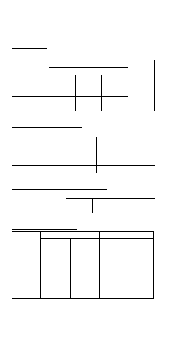
242 Part Number 8014793 6/18
S1600W
All Self-Contained Water-cooled
Characteristics may vary depending on operating conditions.
CYCLE TIMES
Freeze Time + Harvest Time = Total Cycle Time
24 HOUR ICE PRODUCTION
CONDENSER WATER CONSUMPTION
OPERATING PRESSURES
Air Temp.
Around Ice
Machine °F/°C
Freeze Time
Harvest
Time
1
1 Times in minutes
Water Temperature °F/°C
50/10 70/21 90/32
70/21 9.8-10.8 10.9-12.0 12.4-13.6
1 - 2.5
80/27 10.1-11.1 11.0-12.1 12.7-13.9
90/32 10.2-11.2 11.1-12.2 12.8-14.0
100/38 10.4-11.5 11.4-12.5 13.0-14.3
Air Temp. Around Ice
Machine °F/°C
Water Temperature °F/°C
1
1 Based on average ice slab weight of 13 - 14.125 lb.
50/10 70/21 90/32
70/21 1660 1510 1350
80/27 1610 1500 1320
90/32 1600 1480 1310
100/38 1570 1450 1290
Air Temp. Around Ice
Machine 90°F/32°C
Gal/100 lbs. of Ice
Water Temperature °F/°C
1
1 Water regulating valve set to maintain 240 PSIG discharge pressure
50/10 70/21 90/32
100 150 550
Air Temp.
Around Ice
Machine
°F/°C
Freeze Cycle Harvest Cycle
Discharge
Pressure
PSIG
Suction
Pressure
PSIG
1
1 Suction pressure drops gradually throughout the freeze cycle
Discharge
Pressure
PSIG
Suction
Pressure
PSIG
50/10.0 235-245 46-27 160-175 70-90
70/21.1 235-275 50-27 160-180 70-95
80/26.7 240-280 52-28 160-190 70-100
90/32.2 240-285 52-28 160-190 75-100
100/37.8 250-290 52-29 165-195 75-100
110/43.3 255-295 52-30 170-200 80-100

Part Number 8014793 6/18 243
S1600N
All Remote Air-cooled Condenser
Characteristics may vary depending on operating conditions.
CYCLE TIMES
Freeze Time + Harvest Time = Total Cycle Time
24 HOUR ICE PRODUCTION
OPERATING PRESSURES
Air Temp.
Entering
Condenser
°F/°C
Freeze Time
Harvest
Time
1
1 Times in minutes
Water Temperature °F/°C
50/10 70/21 90/32
-20/-29 to 70/21 10.4-11.5 11.2-12.3 12.4-13.6
1 - 2.5
80/27 10.5-11.5 11.7-12.8 12.5-13.7
90/32 10.8-11.9 11.7-12.8 13.0-14.3
100/38 11.7-12.8 12.9-14.1 13.8-15.2
110/43 10.4-11.5 11.2-12.3 12.4-13.6
Air Temp. Entering
Condenser
°F/°C
Water Temperature °F/°C
12
1 Based on average ice slab weight of 13 - 14.125 lb.
2 Ratings with JC1395 condenser
50/10 70/21 90/32
-20/-29 to 70/21 1570 1470 1350
80/27 1560 1420 1340
90/32 1520 1420 1290
100/38 1420 1300 1220
110/43 1570 1470 1350
Air Temp.
Entering
Condenser
°F/°C
Freeze Cycle Harvest Cycle
Discharge
Pressure
PSIG
Suction
Pressure
PSIG
1
1 Suction pressure drops gradually throughout the freeze cycle
Discharge
Pressure
PSIG
Suction
Pressure
PSIG
-20/-29 to
50/10
220-230 40-28 100-160 65-85
70/21 250-275 50-28 100-170 70-85
80/27 250-290 50-28 100-175 70-90
90/32 255-300 52-30 100-175 75-95
100/38 270-340 54-31 110-180 75-95
110/43 310-370 56-32 120-190 80-100

244 Part Number 8014793 6/18
S1800 SERIES
S1800 Self-contained air-cooled
All Self-Contained Air-cooled with a Manufacture Date
Before 0910 (October 2009)
Characteristics may vary depending on operating conditions.
CYCLE TIMES
Freeze Time + Harvest Time = Total Cycle Time
24 HOUR ICE PRODUCTION
OPERATING PRESSURES
Air Temp.
Entering
Condenser
°F/°C
Freeze Time
Harvest
Time
1
1 Times in minutes
Water Temperature °F/°C
50/10 70/21 90/32
70/21 8.7-9.6 9.6-10.6 10.4-11.5
1 - 2.5
80/27 9.4-10.3 10.2-11.2 10.9-12.0
90/32 10.0-11.0 10.7-11.8 11.8-12.9
100/38 11.2-12.3 12.2-13.3 13.0-14.3
Air Temp. Entering
Condenser °F/°C
Water Temperature °F/°C
1
1 Based on average ice slab weight of 13 - 14.125 lb.
50/10 70/21 90/32
70/21 1830 1680 1570
80/27 1720 1600 1510
90/32 1630 1530 1410
100/38 1470 1370 1290
Air Temp
Entering
Condenser
°F/°C
Freeze Cycle Harvest Cycle
Discharge
Pressure
PSIG
Suction
Pressure
PSIG
1
1 Suction pressure drops gradually throughout the freeze cycle
Discharge
Pressure
PSIG
Suction
Pressure
PSIG
50/10 220-280 40-25 160-170 70-85
70/21 220-280 40-26 160-180 70-85
80/27 225-290 42-28 175-200 80-95
90/32 260-330 44-28 175-200 80-95
100/38 300-380 46-30 190-215 90-110
110/43 320-415 50-30 210-250 105-140

Part Number 8014793 6/18 245
SD1802A
Dice Cube, Self-Contained Air-cooled with a Manufacture
Date After 0910 (October 2009)
Characteristics may vary depending on operating conditions.
CYCLE TIMES
Freeze Time + Harvest Time = Total Cycle Time
24 HOUR ICE PRODUCTION
OPERATING PRESSURES
Air Temp.
Entering
Condenser
°F/°C
Freeze Time
Harvest
Time
1
1 Times in minutes
Water Temperature °F/°C
50/10 70/21 90/32
70/21 8.9-10.1 9.7-11.0 10.5-12.0
1 - 2.5
80/27 9.7-11.0 10.6-12.1 11.6-13.2
90/32 10.5-11.9 11.5-13.1 12.7-14.4
100/38 11.5-13.1 12.8-14.5 14.2-16.1
110/43 12.9-14.6 14.5-16.4 16.3-18.4
Air Temp. Entering
Condenser °F/°C
Water Temperature °F/°C
1
1 Based on average ice slab weight of 13 - 14.125 lb.
50/10 70/21 90/32
70/21 1830 1700 1580
80/27 1700 1570 1450
90/32 1590 1460 1340
100/38 1460 1330 1210
110/43 1320 1190 1070
Air Temp
Entering
Condenser
°F/°C
Freeze Cycle Harvest Cycle
Discharge
Pressure
PSIG
Suction
Pressure
PSIG
1
1 Suction pressure drops gradually throughout the freeze cycle
Discharge
Pressure
PSIG
Suction
Pressure
PSIG
50/10 220-280 40-24 150-180 70-90
70/21 220-280 40-26 160-180 70-90
80/27 240-290 50-27 160-180 70-90
90/32 260-330 50-27 180-200 80-100
100/38 300-370 54-28 200-220 90-115
110/43 330-410 60-30 220-250 100-130
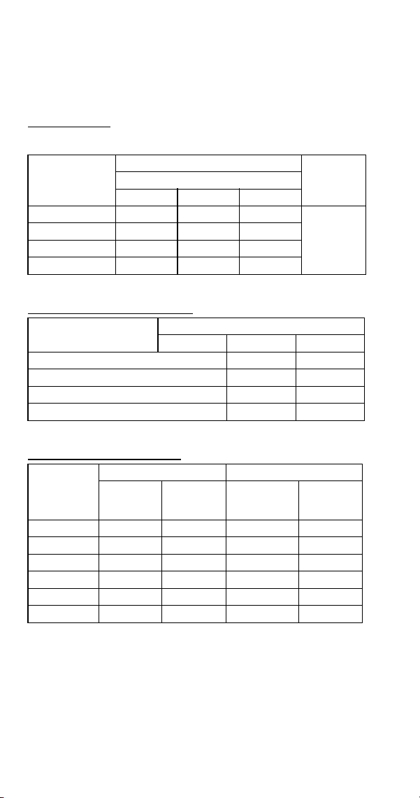
246 Part Number 8014793 6/18
SY1804A
Half Dice Cube, Self-Contained Air-cooled with a
Manufacture Date After 0910 (October 2009)
Characteristics may vary depending on operating conditions.
CYCLE TIMES
Freeze Time + Harvest Time = Total Cycle Time
24 HOUR ICE PRODUCTION
OPERATING PRESSURES
Air Temp.
Entering
Condenser
°F/°C
Freeze Time
Harvest
Time
1
1 Times in minutes
Water Temperature °F/°C
50/10 70/21 90/32
70/21 8.6-9.8 9.6-10.9 10.2-11.7
1 - 2.5
80/27 8.9-10.2 10.0-11.4 10.8-12.2
90/32 9.7-11.1 11.0-12.5 11.9-13.5
100/38 10.7-12.2 12.2-13.8 13.2-15.0
Air Temp. Entering
Condenser °F/°C
Water Temperature °F/°C
1
1 Based on average ice slab weight of 13 - 14.125 lb.
50/10 70/21 90/32
70/21 1890 1720 1620
80/27 1820 1650 1550
90/32 1690 1520 1420
100/38 1560 1390 1290
Air Temp
Entering
Condenser
°F/°C
Freeze Cycle Harvest Cycle
Discharge
Pressure
PSIG
Suction
Pressure
PSIG
1
1 Suction pressure drops gradually throughout the freeze cycle
Discharge
Pressure
PSIG
Suction
Pressure
PSIG
50/10 220-280 40-24 150-180 70-90
70/21 220-280 40-26 160-180 70-90
80/27 240-290 50-27 160-180 70-90
90/32 260-330 50-27 180-200 80-100
100/38 300-370 54-28 200-220 90-115
110/43 330-410 60-30 220-250 100-130
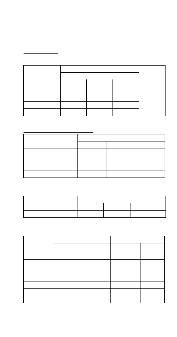
Part Number 8014793 6/18 247
S1800 Self-Contained Water-Cooled
All Self-Contained Water-cooled with a Manufacture Date
Before 0910 (October 2009)
Characteristics may vary depending on operating conditions.
CYCLE TIMES
Freeze Time + Harvest Time = Total Cycle Time
24 HOUR ICE PRODUCTION
CONDENSER WATER CONSUMPTION
OPERATING PRESSURES
Air Temp.
Around Ice
Machine °F/°C
Freeze Time
Harvest
Time
1
1 Times in minutes
Water Temperature °F/°C
50/10 70/21 90/32
70/21 8.5-9.4 9.2-10.1 10.7-11.8
1 - 2.5
80/27 8.5-9.4 9.3-10.3 10.9-12.0
90/32 8.6-9.4 9.4-10.4 11.1-12.2
100/38 8.7-9.6 9.6-10.5 11.2-12.3
Air Temp. Around Ice
Machine °F/°C
Water Temperature °F/°C
1
1 Based on average ice slab weight of 13 - 14.125 lb.
50/10 70/21 90/32
70/21 1870 1750 1530
80/27 1870 1730 1510
90/32 1860 1710 1490
100/38 1830 1690 1470
Air Temp. Around Ice
Machine 90°F/32°C
Water Temperature °F/°C
1
1 Water regulating valve set to maintain 240 PSIG discharge pressure
50/10 70/21 90/32
Gal/100 lbs. of Ice 95 155 510
Air Temp.
Around Ice
Machine
°F/°C
Freeze Cycle Harvest Cycle
Discharge
Pressure
PSIG
Suction
Pressure
PSIG
1
1 Suction pressure drops gradually throughout the freeze cycle
Discharge
Pressure
PSIG
Suction
Pressure
PSIG
50/10 235-245 40-25 160-190 70-90
70/21 235-265 40-26 160-190 70-90
80/27 240-270 42-26 165-190 70-90
90/32 240-275 45-27 165-190 70-90
100/38 245-280 50-28 165-190 70-95
110/43 245-290 52-28 175-200 80-100
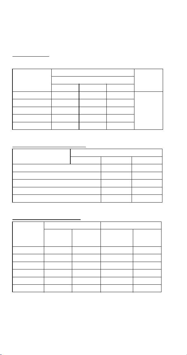
248 Part Number 8014793 6/18
SD1803W
Dice Cube, Self-Contained Water-cooled with a
Manufacture Date After 0910 (October 2009)
Characteristics may vary depending on operating conditions.
CYCLE TIMES
Freeze Time + Harvest Time = Total Cycle Time
24 HOUR ICE PRODUCTION
OPERATING PRESSURES
Air Temp.
Entering
Condenser
°F/°C
Freeze Time
Harvest
Time
1
1 Times in minutes
Water Temperature °F/°C
50/10 70/21 90/32
70/21 8.6-9.8 9.6-11.0 10.8-12.2
1 - 2.5
80/27 8.8-10.0 9.8-11.2 11.0-12.5
90/32 8.8-10.1 9.9-11.3 11.1-12.6
100/38 9.0-10.3 10.1-11.5 11.3-12.9
110/43 9.1-10.4 10.2-11.7 11.5-13.1
Air Temp. Entering
Condenser °F/°C
Water Temperature °F/°C
1
1 Based on average ice slab weight of 13 - 14.125 lb.
50/10 70/21 90/32
70/21 1880 1710 1550
80/27 1850 1680 1520
90/32 1840 1670 1510
100/38 1810 1640 1480
110/43 1790 1620 1460
Air Temp
Entering
Condenser
°F/°C
Freeze Cycle Harvest Cycle
Discharge
Pressure
PSIG
Suction
Pressure
PSIG
1
1 Suction pressure drops gradually throughout the freeze cycle
Discharge
Pressure
PSIG
Suction
Pressure
PSIG
50/10 230-240 45-25 145-165 65-80
70/21 220-280 40-26 160-180 70-90
80/27 230-240 45-25 145-165 65-80
90/32 240-270 50-25 150-190 70-90
100/38 240-270 55-25 155-190 70-90
110/43 240-270 55-25 155-190 70-90
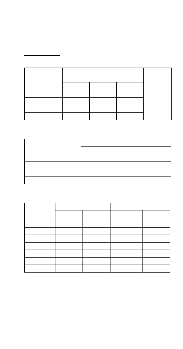
Part Number 8014793 6/18 249
SY1805W
Half Dice Cube, Self-Contained Water-cooled with a
Manufacture Date After 0910 (October 2009)
Characteristics may vary depending on operating conditions.
CYCLE TIMES
Freeze Time + Harvest Time = Total Cycle Time
24 HOUR ICE PRODUCTION
OPERATING PRESSURES
Air Temp.
Entering
Condenser
°F/°C
Freeze Time
Harvest
Time
1
1 Times in minutes
Water Temperature °F/°C
50/10 70/21 90/32
70/21 8.6-9.8 9.1-10.4 10.6-12.1
1 - 2.5
80/27 8.7-10.0 9.3-10.6 10.8-12.3
90/32 8.8-10.0 9.4-10.7 10.9-12.4
100/38 8.9-10.1 9.5-10.8 11.1-12.6
Air Temp. Entering
Condenser °F/°C
Water Temperature °F/°C
1
1 Based on average ice slab weight of 13 - 14.125 lb.
50/10 70/21 90/32
70/21 1890 1790 1570
80/27 1860 1760 1540
90/32 1850 1750 1530
100/38 1830 1730 1510
Air Temp
Entering
Condenser
°F/°C
Freeze Cycle Harvest Cycle
Discharge
Pressure
PSIG
Suction
Pressure
PSIG
1
1 Suction pressure drops gradually throughout the freeze cycle
Discharge
Pressure
PSIG
Suction
Pressure
PSIG
50/10 230-240 45-25 145-165 65-80
70/21 220-280 40-26 160-180 70-90
80/27 230-240 45-25 145-165 65-80
90/32 240-270 50-25 150-190 70-90
100/38 240-270 55-25 155-190 70-90
110/43 240-270 55-25 155-190 70-90
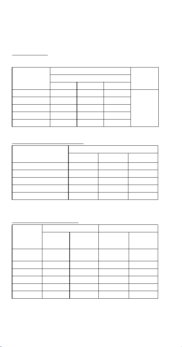
250 Part Number 8014793 6/18
S1800 Remote Air-cooled Condenser
All Remote Condenser Air-cooled with a Manufacture
Date Before 0910 (October 2009)
Characteristics may vary depending on operating conditions.
CYCLE TIMES
Freeze Time + Harvest Time = Total Cycle Time
24 HOUR ICE PRODUCTION
OPERATING PRESSURES
Air Temp.
Entering
Condenser
°F/°C
Freeze Time
Harvest
Time
1
1 Times in minutes
Water Temperature °F/°C
50/10 70/21 90/32
-20/-29 to 70/21 8.9-9.8 10.0-11.0 10.7-11.7
1 - 2.5
80/27 9.0-9.9 10.1-11.1 10.8-11.9
90/32 9.2-10.1 10.1-11.1 10.8-11.9
100/38 9.6-10.5 10.0-11.0 11.6-12.7
110/43 10.4-11.5 11.5-12.6 12.5-13.7
Air Temp. Entering
Condenser
°F/°C
Water Temperature °F/°C
12
1 Based on average ice slab weight of 13 - 14.125 lb
2 Ratings with JC1395 condenser
50/10 70/21 90/32
-20/-29 to 70/21 1800 1630 1540
80/27 1780 1620 1520
90/32 1750 1610 1520
100/38 1690 1630 1430
110/43 1570 1440 1340
Air Temp.
Entering
Condenser
°F/°C
Freeze Cycle Harvest Cycle
Discharge
Pressure
PSIG
Suction
Pressure
PSIG
1
1 Suction pressure drops gradually throughout the freeze cycle
Discharge
Pressure
PSIG
Suction
Pressure
PSIG
-20/-29 to
50/10
220-250 44-26 110-170 65-85
70/21 240-280 50-28 115-180 70-90
80/27 245-290 50-28 115-180 70-90
90/32 250-300 52-28 120-195 70-90
100/38 260-340 60-28 125-210 70-90
110/43 295-390 60-30 125-220 80-100
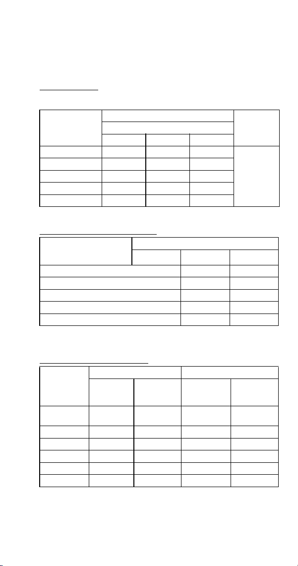
Part Number 8014793 6/18 251
SD1892N
Dice Cube, Remote Condenser Air-cooled with a
Manufacture Date After 0910 (October 2009)
Characteristics may vary depending on operating conditions.
CYCLE TIMES
Freeze Time + Harvest Time = Total Cycle Time
24 HOUR ICE PRODUCTION
OPERATING PRESSURES
Air Temp.
Entering
Condenser
°F/°C
Freeze Time
Harvest
Time
1
1 Times in minutes
Water Temperature °F/°C
50/10 70/21 90/32
-20/-29 to 70/21 9.4-10.7 10.3-11.7 11.1-12.6
1 - 2.5
80/27 9.5-10.8 10.5-11.9 11.3-12.8
90/32 10.0-11.4 11.1-12.6 12.0-13.6
100/38 10.8-12.2 12.0-13.6 13.0-14.8
110/43 11.7-13.3 13.1-14.9 14.3-16.3
Air Temp. Entering
Condenser
°F/°C
Water Temperature °F/°C
12
1 Based on average ice slab weight of 13 - 14.125 lb
2 Ratings with JC1395 condenser
50/10 70/21 90/32
-20/-29 to 70/21 1750 1610 1510
80/27 1730 1590 1490
90/32 1650 1510 1410
100/38 1550 1410 1310
110/43 1440 1300 1200
Air Temp.
Entering
Condenser
°F/°C
Freeze Cycle Harvest Cycle
Discharge
Pressure
PSIG
Suction
Pressure
PSIG
1
1 Suction pressure drops gradually throughout the freeze cycle
Discharge
Pressure
PSIG
Suction
Pressure
PSIG
-20/-29 to
50/10
230-265 38-24 100-160 70-85
70/21 240-265 40-26 110-170 70-90
80/27 250-275 45-28 110-180 70-95
90/32 250-300 52-29 110-180 70-95
100/38 275-335 55-31 110-185 75-100
110/43 310-385 55-32 120-190 80-110
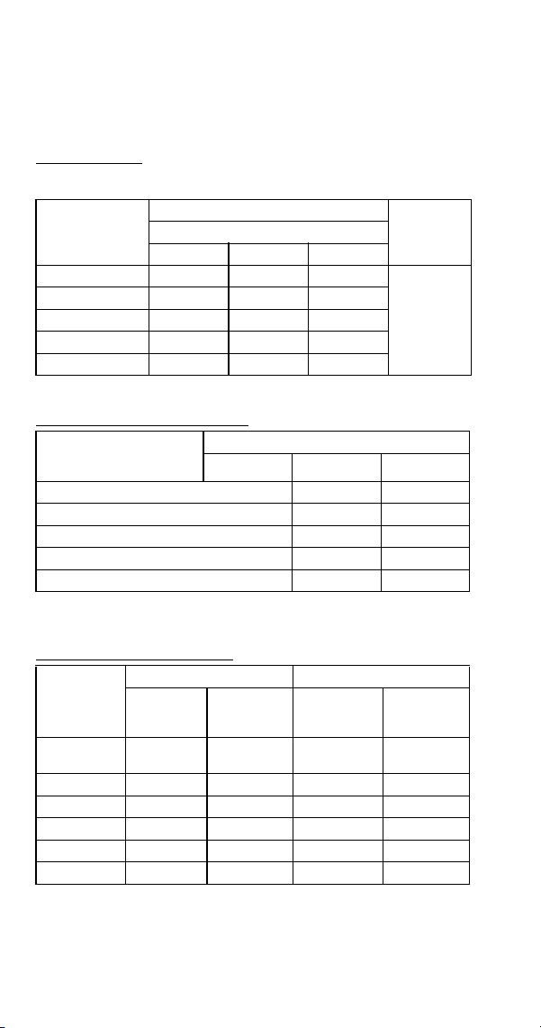
252 Part Number 8014793 6/18
SY1894N
Half Dice Cube, Remote Condenser Air-cooled with a
Manufacture Date After 0910 (October 2009)
Characteristics may vary depending on operating conditions.
CYCLE TIMES
Freeze Time + Harvest Time = Total Cycle Time
24 HOUR ICE PRODUCTION
OPERATING PRESSURES
Air Temp.
Entering
Condenser
°F/°C
Freeze Time
Harvest
Time
1
1 Times in minutes
Water Temperature °F/°C
50/10 70/21 90/32
-20/-29 to 70/21 9.2-10.5 10.0-11.4 10.8-12.2
1 - 2.5
80/27 9.6-10.9 10.4-11.8 11.2-12.7
90/32 10.2-11.6 10.8-12.3 11.7-13.3
100/38 10.8-12.2 11.5-13.1 12.5-14.2
110/43 11.8-13.4 12.7-14.4 13.8-15.7
Air Temp. Entering
Condenser
°F/°C
Water Temperature °F/°C
12
1 Based on average ice slab weight of 13 - 14.125 lb
2 Ratings with JC1395 condenser
50/10 70/21 90/32
-20/-29 to 70/21 1770 1650 1550
80/27 1720 1600 1500
90/32 1630 1540 1440
100/38 1550 1460 1360
110/43 1430 1340 1240
Air Temp.
Entering
Condenser
°F/°C
Freeze Cycle Harvest Cycle
Discharge
Pressure
PSIG
Suction
Pressure
PSIG
1
1 Suction pressure drops gradually throughout the freeze cycle
Discharge
Pressure
PSIG
Suction
Pressure
PSIG
-20/-29 to
50/10
230-265 38-24 100-160 70-85
70/21 240-265 40-26 110-170 70-90
80/27 250-275 45-28 110-180 70-95
90/32 250-300 52-29 110-180 70-95
100/38 275-335 55-31 110-185 75-100
110/43 310-385 55-32 120-190 80-110
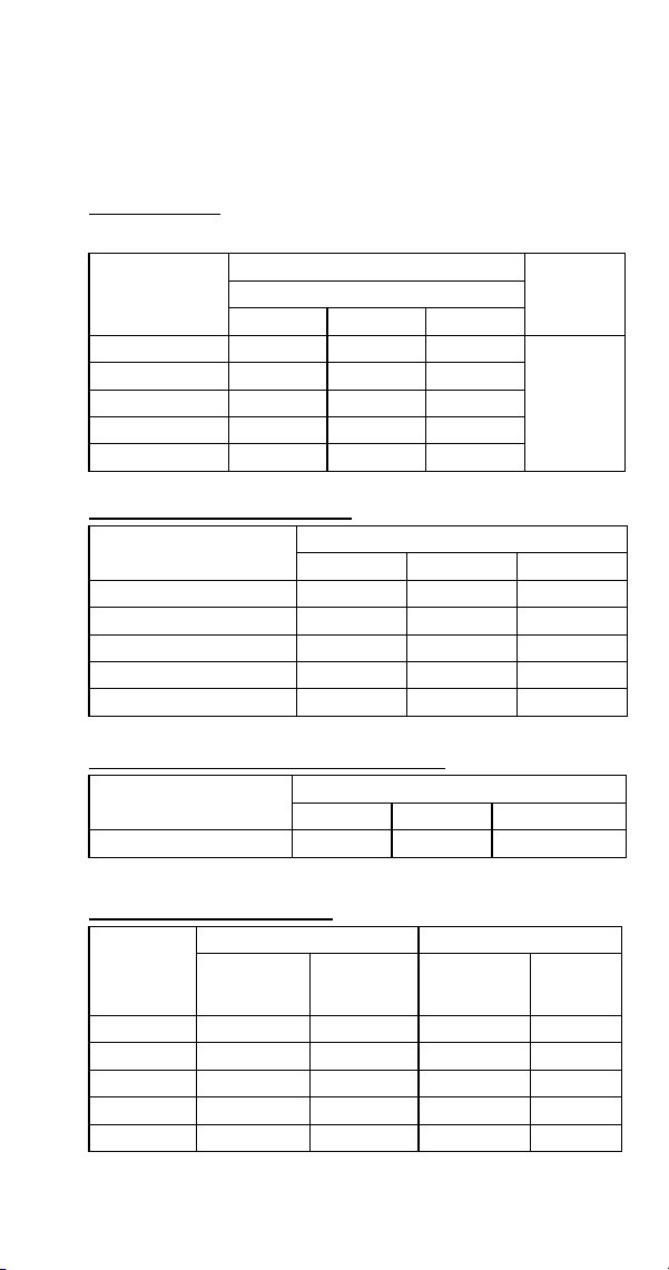
Part Number 8014793 6/18 253
S3300 SERIES
SDT3000W Self Contained Water-Cooled
All Dice Cube, Self-Contained Water-cooled Ice Machines
Characteristics may vary depending on operating conditions.
CYCLE TIMES
Freeze Time + Harvest Time = Total Cycle Time
24 HOUR ICE PRODUCTION
CONDENSER WATER CONSUMPTION
OPERATING PRESSURES
Air Temp.
Around Ice
Machine °F/°C
Freeze Time
Harvest
Time
1
1 Times in minutes
Water Temperature °F/°C
50/10 70/21 90/32
70/21 10.9-12.3 11.9-13.4 13.8-15.6
0.75 - 2.5
80/27 11.0-12.5 12.1-13.7 14.1-15.9
90/32 11.1-12.6 12.6-14.2 14.3-16.2
100/38 11.2-12.6 12.7-14.4 14.5-16.4
110/43 11.2-12.7 12.9-14.5 14.6-16.5
Air Temp. Around Ice
Machine °F/°C
Water Temperature °F/°C
1
1 Based on average ice slab weight of 6.38-7.13 lb. per evaporator.
50/10 70/21 90/32
70/21 2970 2750 2395
80/27 2940 2705 2355
90/32 2920 2610 2325
100/38 2905 2580 2300
110/43 2885 2560 2280
Air Temp. Around Ice
Machine 90°F/32°C
Water Temperature °F/°C
1
1 Water regulating valve set to maintain 330 PSIG discharge pressure
50/10 70/21 90/32
Gal/100 lbs. of Ice 52 108 358
Air Temp.
Around Ice
Machine
°F/°C
Freeze Cycle Harvest Cycle
Discharge
Pressure
PSIG
Suction
Pressure
PSIG
1
1 Suction pressure drops gradually throughout the freeze cycle
Discharge
Pressure
PSIG
Suction
Pressure
PSIG
70/21 325-335 60-44 180-200 95-115
80/27 325-335 70-45 185-205 110-125
90/32 325-335 75-45 180-210 110-125
100/38 325-335 75-45 180-210 110-125
110/43 335-355 80-45 185-220 110-125
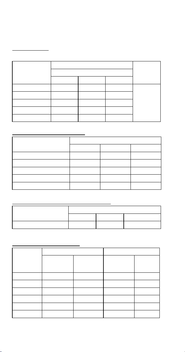
254 Part Number 8014793 6/18
SYT3000W Self Contained Water-Cooled
All Dice Cube, Self-Contained Water-cooled Ice Machines
Characteristics may vary depending on operating conditions.
CYCLE TIMES
Freeze Time + Harvest Time = Total Cycle Time
24 HOUR ICE PRODUCTION
CONDENSER WATER CONSUMPTION
OPERATING PRESSURES
Air Temp.
Around Ice
Machine °F/°C
Freeze Time
Harvest
Time
1
1 Times in minutes
Water Temperature °F/°C
50/10 70/21 90/32
70/21 10.7-12.1 11.5-13.0 13.3-15.1
0.75 - 2.5
80/27 10.8-12.3 11.8-13.4 13.7-15.5
90/32 10.9-12.4 12.2-13.9 13.9-15.7
100/38 11.0-12.4 12.4-14.0 14.0-15.9
110/43 11.1-12.5 12.5-14.1 14.2-16.1
Air Temp. Around Ice
Machine °F/°C
Water Temperature °F/°C
1
1 Based on average ice slab weight of 6.38-7.13 lb. per evaporator.
50/10 70/21 90/32
70/21 3015 2815 2480
80/27 2985 2765 2425
90/32 2965 2675 2390
100/38 2950 2645 2365
110/43 2925 2625 2340
Air Temp. Around Ice
Machine 90°F/32°C
Water Temperature °F/°C
1
1 Water regulating valve set to maintain 330 PSIG discharge pressure
50/10 70/21 90/32
Gal/100 lbs. of Ice 52 108 358
Air Temp.
Around Ice
Machine
°F/°C
Freeze Cycle Harvest Cycle
Discharge
Pressure
PSIG
Suction
Pressure
PSIG
1
1 Suction pressure drops gradually throughout the freeze cycle
Discharge
Pressure
PSIG
Suction
Pressure
PSIG
50/10 325-335 60-44 180-200 95-115
70/21 325-335 70-45 185-205 110-125
80/27 325-335 75-45 180-210 110-125
90/32 325-335 75-45 180-210 110-125
100/38 335-355 80-45 185-220 110-125
110/43 325-335 60-44 180-200 95-115
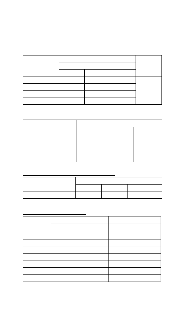
Part Number 8014793 6/18 255
SD3303W Self-Contained Water-Cooled
All Dice Cube, Self-Contained Water-cooled Ice Machines
Characteristics may vary depending on operating conditions.
CYCLE TIMES
Freeze Time + Harvest Time = Total Cycle Time
24 HOUR ICE PRODUCTION
CONDENSER WATER CONSUMPTION
OPERATING PRESSURES
Air Temp.
Around Ice
Machine °F/°C
Freeze Time
Harvest
Time
1
1 Times in minutes
Water Temperature °F/°C
50/10 70/21 90/32
70/21 9.6-10.9 11.1-12.6 12.7-14.4
0.75 - 2.5
80/27 9.7-11.0 11.3-12.8 13.0-14.7
90/32 9.9-11.2 11.5-13.1 13.3-15.0
100/38 10.0-11.4 11.7-13.3 13.5-15.3
Air Temp. Around Ice
Machine °F/°C
Water Temperature °F/°C
1
1 Based on average ice slab weight of 6.38-7.13 lb. per evaporator.
50/10 70/21 90/32
70/21 3320 2920 2580
80/27 3280 2880 2540
90/32 3220 2820 2480
100/38 3180 2780 2440
Air Temp. Around Ice
Machine 90°F/32°C
Water Temperature °F/°C
1
1 Water regulating valve set to maintain 240 PSIG discharge pressure
50/10 70/21 90/32
Gal/100 lbs. of Ice 97 166 419
Air Temp.
Around Ice
Machine
°F/°C
Freeze Cycle Harvest Cycle
Discharge
Pressure
PSIG
Suction
Pressure
PSIG
1
1 Suction pressure drops gradually throughout the freeze cycle
Discharge
Pressure
PSIG
Suction
Pressure
PSIG
50/10 230-240 40-30 110-160 75-100
70/21 230-250 45-30 125-160 75-100
80/27 230-250 50-31 125-160 75-100
90/32 260-280 50-31 130-160 75-110
100/38 260-290 50-31 130-180 75-110
110/43 260-290 50-31 130-190 80-110
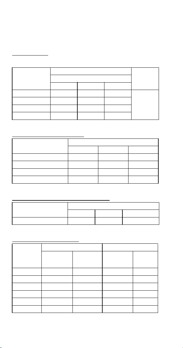
256 Part Number 8014793 6/18
SY3305W
All Half Dice Cube, Self-Contained Water-cooled Ice
Machines
Characteristics may vary depending on operating conditions.
CYCLE TIMES
Freeze Time + Harvest Time = Total Cycle Time
24 HOUR ICE PRODUCTION
CONDENSER WATER CONSUMPTION
OPERATING PRESSURES
Air Temp.
Around Ice
Machine °F/°C
Freeze Time
Harvest
Time
1
1 Times in minutes
Water Temperature °F/°C
50/10 70/21 90/32
70/21 9.4-10.6 10.5-12.0 12.4-14.0
0.75 - 2.5
80/27 9.6-10.9 10.9-12.3 12.8-14.5
90/32 9.8-11.1 11.0-12.5 13.1-14.8
100/38 9.9-11.3 11.2-12.7 13.3-15.0
Air Temp. Around Ice
Machine °F/°C
Water Temperature °F/°C
1
1 Based on average ice slab weight of 6.38-7.13 lb. per evaporator
50/10 70/21 90/32
70/21 3380 3050 2640
80/27 3300 2970 2560
90/32 3260 2930 2520
100/38 3210 2890 2480
Air Temp. Around Ice
Machine 90°F/32°C
Water Temperature °F/°C
1
1 Water regulating valve set to maintain 240 PSIG discharge pressure
50/10 70/21 90/32
Gal/100 lbs. of Ice 97 166 419
Air Temp.
Around Ice
Machine
°F/°C
Freeze Cycle Harvest Cycle
Discharge
Pressure
PSIG
Suction
Pressure
PSIG
1
1 Suction pressure drops gradually throughout the freeze cycle
Discharge
Pressure
PSIG
Suction
Pressure
PSIG
50/10 230-240 40-30 110-160 75-100
70/21 230-250 45-30 125-160 75-100
80/27 230-250 50-31 125-160 75-100
90/32 260-280 50-31 130-160 75-110
100/38 260-290 50-31 130-180 75-110
110/43 260-290 50-31 130-190 80-110

Part Number 8014793 6/18 257
Diagrams
Wiring Diagrams
The following pages contain electrical wiring diagrams.
Be sure you are referring to the correct diagram for the
ice machine you are servicing.
Some components are wired differently on energy
efficient machines. Please verify your serial number
(page 12) to reference the correct diagrams.
WIRING DIAGRAM LEGEND
The following symbols are used on all of the wiring
diagrams:
* Internal Compressor Overload
(Some models have external
compressor overloads)
** Fan Motor Run Capacitor
(Some models do not incorporate fan
motor run capacitor)
( ) Wire Number Designation
(The number is marked at each end of
the wire)
—>>— Multi-Pin Connection
(Electrical Box Side) —>>—
(Compressor Compartment Side)
!
Warning
Always disconnect power before working on
electrical circuitry.
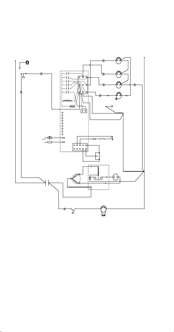
258 Part Number 8014793 6/18
WIRING DIAGRAMS BEFORE ENERGY EFFICIENT
& ENERGYSTAR MACHINES
S320
Self Contained - 1 Phase
(48)
R
S
C
CLEAN
OFF
ICE
BIN
SWITCH
LOW D.C.
VOLTAGE
PLUG
CONTACTOR
COIL
(56)
TERMINATES AT
PIN CONNECTION
(74)
PUMP
WATER
(99)
(98)
(58)
FUSE (7A)
TRANS.
ICE THICKNESS
PROBE
WATER LEVEL
PROBE
SOLENOID
(57)
DUMP
(81)
(75)
(76)
HARVEST
SOLENOID
(80)
(77)
VALVE
WATER
(60)
(61)
(22)
(21)
(7)
(2)
(1)
(6)
(5)
HIGH PRESSURE
CUTOUT
(55)
L2 OR N
SEE SERIAL PLATE FOR VOLTAGE
L1
(89)
(88)
(20)
(59)
CLEAN
LEFT BIN
RIGHT BIN
RMT BIN
WTR PROBE
ICE PROBE
HARV
SL-1
SL-2
(6)
(2)
(1)
(9)
(8)
(42)
CONTROL BOARD
(4)
(85)
(51)
CONTACTOR
CONTACTS
L1
FAN CYCLE CONTROL
RUN CAPACITOR**
FAN MOTOR
(AIR COOLED ONLY)
(49)
START
CAPACITOR
CURRENT
RELAY
11
12
13
10
14
GROUND
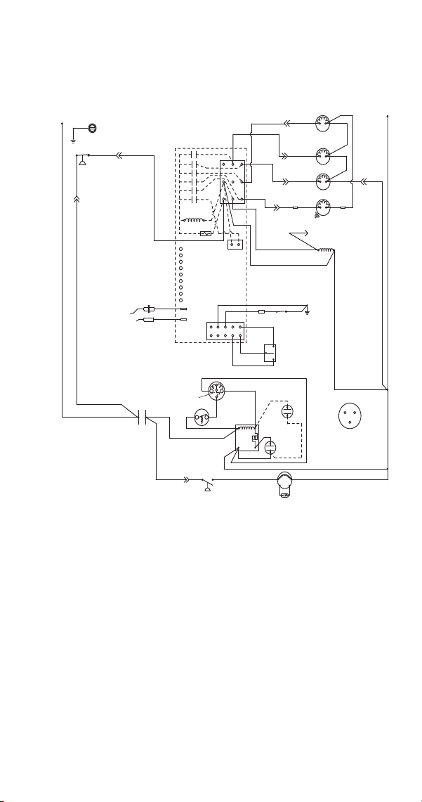
Part Number 8014793 6/18 259
S300/S420/S450/
S500 (after serial number 110074051) -
Self Contained - 1 Phase
SV3137A
(89)
(55)
(88)
(42)
High Pressure
Cutout
Water Valve
Harvest Valve
Dump Valve
Water Pump
Terminates at
Pin Connection
(20)
(21)
(22)
(74)
Ice Thickness
Probe
Water Level
Probe
Control Board
(61)
(60)
(57)
(98)
(99)
(76)
(81)
(75)
(77)
(80)
(58)
(59)
Contactor Coil
(56)
Trans.
Fuse (7a)
Low DC
Voltage
Plug
L1
(51)
(85)
(86)
Fan Cycle
Control
Fan Motor
Run
Capacitor
5
Compressor
Run
Capacitor
(50)
(45)
L2 or N
L1
Ground
(2)
(6)
(5)
(1)
(7)
(4)
L2
Bin Switch
Clean
OFF
ICE
(2)
(1)
(6)
(8)
(9)
Overload
Contactor
Contacts
(46)
Compressor
Terminal Layout
Viewed from End
of Compressor
(49)
2
1
4
(48)
(53)
(52)
(44)
S
C
R
(47)
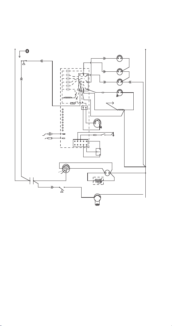
260 Part Number 8014793 6/18
S500 (before serial number 110074051)
S600/S850/S1000/S1200-
Self Contained- 1 Phase
SV3130
(89) (55)
(88)
(42)
High Pressure
Cutout
Water Valve
Harvest Valve
Dump Valve
Water Pump
Terminates at
Pin Connection
(20)
(21)
(22)
(74)
Ice Thickness
Probe
Water Level
Probe
Control Board
(61)
(60)
(57) (98)
(99)
(76)
(81)
(75)
(77)
(80)
(26)
(25)
(58)
(59)
Contactor Coil
(56)
Trans.
Fuse (7a)
Low DC
Voltage
Plug
L1
(51)
(85)
(86)
Fan Cycle
Control
Fan Motor
Run Capacitor
PTCR
Compressor
Run Capacitor
(50)
(45)
L2 or N
L1
Ground
(2)
(6)
(5)
(1)
(7)
(4)
L2
Air
Comp
Air Pump
Bin Switch
Clean
OFF
ICE
(2)
(1)
(6)
(8)
(9)
Overload
(Red)
(Yellow)
(Black)
Contactor
Contacts
(46)
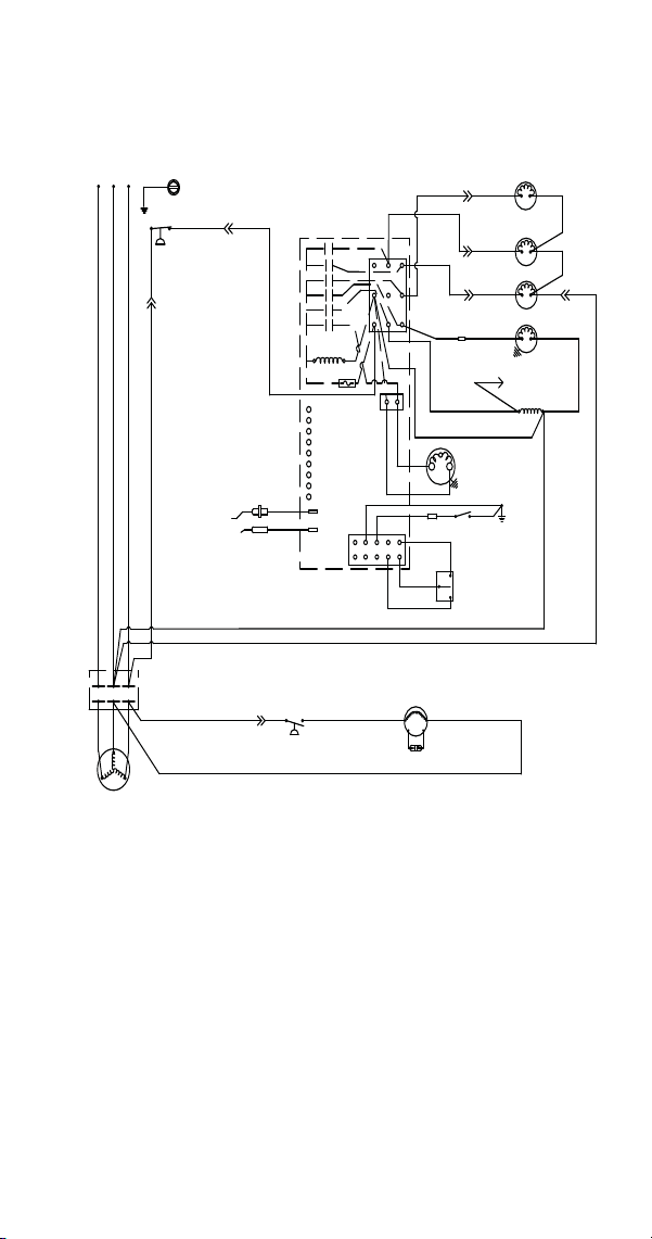
Part Number 8014793 6/18 261
S850/S1000/S1200 -
Self Contained - 3 Phase
SV3131
(89)
(55)
(88)
(42)
High Pressure
Cutout
Water Valve
Harvest Valve
Dump Valve
Water Pump
(20)
(21)
(74)
Ice Thickness
Probe
Water Level
Probe
Control Board
(61)
(60)
(57) (98)
(99)
(76)
(81)
(75)
(77)
(80)
(26)
(25)
(58)
(59)
Contactor Coil
(56)
Trans.
Fuse (7a)
Low DC
Voltage
Plug
L1
(51)
(85)
(86)
Fan Cycle
Control
Fan Motor
Run Capacitor
Ground
(2)
(6)
(5)
(1)
(7)
(4)
L2
Air
Comp
Air Pump
Bin Switch
Clean
OFF
ICE
(2)
(1)
(6)
(8)
(9)
Contactor
Contacts
Terminates at
Pin Connection
Compressor
L2
L3
T1
T2
T3
L1
L2L3
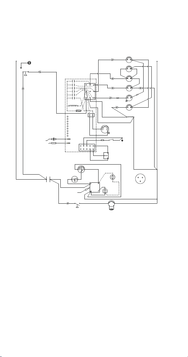
262 Part Number 8014793 6/18
S500 Danfoss Compressor
(after serial number 110074051) -
Remote - 1 Phase
(49)
(47)
COMPRESSOR
OVERLOAD INTERNAL
{230V 50/60 HZ}
R
C
S
(86)
(85)
(51)
(48)
CONTACTOR
CONTACTS
L1
FAN CYCLE CONTROL
RUN CAPACITOR**
FAN MOTOR
(AIR COOLED ONLY)
(50)
5
2
1
4
(46)
(44)
(45)
START
CAPACITOR
POTENTIAL
RELAY
C
S
R
COMPRESSOR
TERMINAL LAYOUT
VIEWED FROM END
OF COMPRESSOR
(53)
RUN
CAPACITOR
(52)
CLEAN
OFF
ICE
BIN
SWITCH
LOW D.C.
VOLTAGE
PLUG
CONTACTOR
COIL
(56)
(74)
PUMP
WATER
(98)
(58)
FUSE (7A)
TRANS.
ICE THICKNESS
PROBE
WATER LEVEL
PROBE
SOLENOID
(57)
DUMP
(81)
(75)
(76)
SOLENOID
HARVEST
(80)
(77)
HPR
SOLENOID
(60)
(61)
(22)
(82)
(7)
(2)
(1)
(6)
(5)
HIGH PRESSURE
CUTOUT
(55)
L2 OR N
SEE SERIAL PLATE FOR VOLTAGE
L1
CAUTION: DISCONNECT POWER BEFORE
WORKING ON ELECTRICAL
CIRCUITRY.
(89)
(88)
(78)
(59)
CLEAN
LEFT BIN
RIGHT BIN
RMT BIN
WTR PROBE
ICE PROBE
HARV
SL-1
SL-2
AIR
PUMP
WHEN USED
(6)
(1)
(25)
(26)
L2
AIR
PUMP
(9)
(8)
(42)
CONTROL BOARD
(4)
LIQUID
SOLENOID
(83)
(79)
WATER
VALV E
(21)
(20)
(99)
(2)
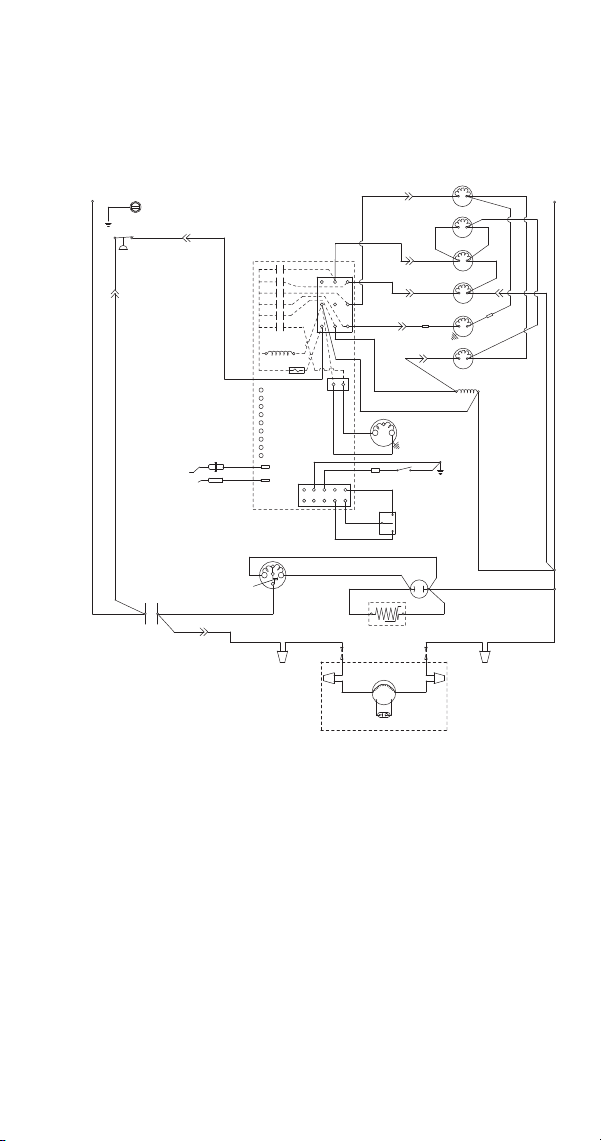
Part Number 8014793 6/18 263
S500 (before serial number 110074051)/
S600/S850/S1000/S1200 -
Remote - 1 Phase
SV3158
(89) (55)
(88)
(42)
High Pressure
Cutout
Water Valve
Harvest Valve
Dump Valve
Water Pump
(20)
(21)
(22)
(74)
Ice Thickness
Probe
Water Level
Probe
Control Board
(61)
(60)
(57)
(98)
(99)
(76)
(80)
(75)
(77)
(26)
(25)
(58)
(59)
Contactor
Coil
(56)
Trans.
Low DC
Voltage
Plug
L1
(51)
Fan Motor
Run Capacitor
PTCR
Compressor
Run Capacitor
(50)
(45)
L2 or
N
L1
Ground
(1)
(2)
(5)
(6)
L2
Air Pump
Bin Switch
Clean
OFF
ICE
(2)
(1)
(6)
(8)
(9)
Overload
(Red)
(Yellow)
(Black)
Contactor
Contacts
(46)
HPR Valve
(78)
(79)
(81)
(22)
(83)
(7)
(4)
Fuse (7a)
(F1) (F2)
Remote Condenser
Liquid
Solenoid
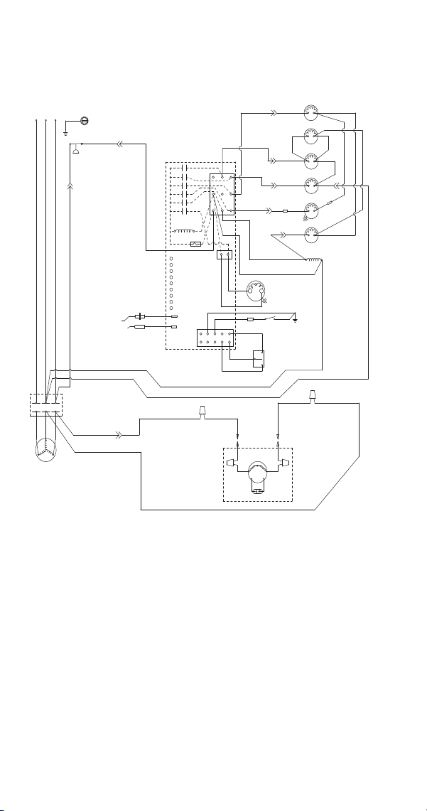
264 Part Number 8014793 6/18
S850/S1000/S1200 -
Remote - 3 Phase
SV3131
(89) (55)
(88)
(42)
High Pressure
Cutout
Water Valve
Harvest Valve
Dump Valve
Water Pump
(20)
(21)
(74)
Ice Thickness
Probe
Water Level
Probe
Control Board
(61)
(60)
(57)
(98)
(99)
(76)
(81)
(75)
(78)
(80)
(26)(25)
(58)
(59)
Contactor
Coil
(56)
Trans.
Fuse (7a)
Low DC
Voltage
Plug
L1
(51)
Fan
Motor
Run Capacitor
Ground
(2)
(6)
(5)
(1)
(7)
(4)
L2
Air Pump
Bin Switch
Clean
OFF
ICE
(2)
(1)
(6)
(8)
(9)
Contactor
Contacts
Compressor
L2
L3
T1
T2
T3
L1
L2L3
(22)
HPR Valve
Liquid Solenoid
(77)
(79)
(82)
(22)
(83)
(F1)
(F2)
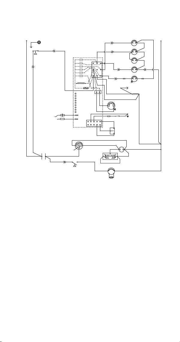
Part Number 8014793 6/18 265
S1400/S1600/S1800 -
Self-Contained - 1 Phase
(2)
(1)
R
S
CLEAN
OFF
ICE
RUN
CAPACITOR
(50)
(45)
R
(46)
PTCR
(AIR COOLED ONLY)
FAN MOTOR
RUN CAPACITOR**
(86)(85)
(51)
(BLACK)
*OVERLOAD
C
R
COMPRESSOR
(YELLOW)
(RED)
CONTACTOR
L1
CONTACTS
FAN CYCLE
CONTROL
(59)
CLEAN
LEFT BIN
RIGHT BIN
RMT BIN
WTR PROBE
ICE PROBE
HARVEST
SL-1
SL-2
(6)
(25)
(26)
L2
AIR
PUMP
(9)
(8)
(42)
CONTROL BOARD
BIN
SWITCH
LOW D.C.
VOLTAGE
PLUG
CONTACTOR
COIL
(56)
TERMINATES AT
PIN CONNECTION
PUMP
WATER
(99)
(98)
(58)
FUSE (7A)
TRANS.
ICE THICKNESS
WATER LEVEL
SOLENOID
(57)
DUMP
(81)
(76)
LH HARVEST
SOLENOID
(87)
(77)
WATER
VALVE
(60)
(61)
(22)
(21)
(7)
(2)
(1)
(5)
HIGH PRESSURE
CUTOUT
(55)
L2 OR N
(88)
(20)
AIR
PUMP
WHEN USED
(4)
(6)
RH HARVEST
SOLENOID
(80)
(88)
(74)
PROBE
PROBE
(75)
L1
(89)
(44)
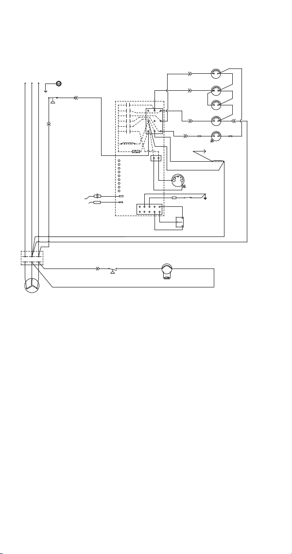
266 Part Number 8014793 6/18
S1400/S1600/S1800 -
Self-Contained - 3 Phase
(42)
CONTROL BOARD
CLEAN
OFF
ICE
BIN
SWITCH
(8)
LOW D.C.
VOLTAGE
PLUG
CONTACTOR
COIL
(56)
TERMINATES AT
PIN CONNECTION
(74)
PUMP
WATER
(58)
ICE THICKNESS
PROBE
WATER LEVEL
PROBE
SOLENOID
DUMP
(81)
(75)
(76)
LH HARVEST
SOLENOID
(87)
(77)
VALVE
WATER
(60)
(61)
(22)
(21)
(7)
(2)
(1)
(6)
(5)
HIGH PRESSURE
CUTOUT
(55)
(89)
(88)
(20)
(59)
CLEAN
LEFT BIN
RIGHT BIN
RMT BIN
WTR PROBE
ICE PROBE
HARV
SL-1
SL-2
AIR
PUMP
WHEN USED
(6)
(2)
(1)
(9)
(25)
(26)
L2
AIR
PUMP
FAN CYCLE CONTROL
T3
L2
L3
COMPRESSOR
T1
T2
(51)
(85)
(86)
CONTACTS
CONTACTOR
L1
L2
L3
L1
(AIR COOLED ONLY)
FAN MOTOR
RUN CAPACITOR**
FUSE (7A)
TRANS.
(4)
(99)
(98)
(57)
RH HARVEST
SOLENOID
(80)
(88)
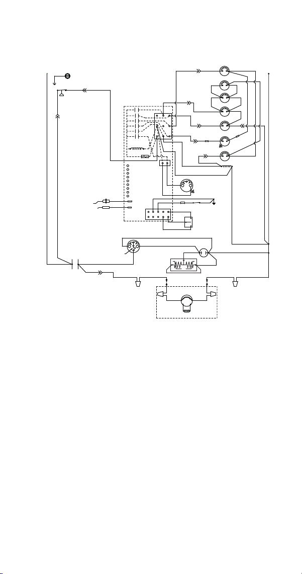
Part Number 8014793 6/18 267
S1400/S1600/S1800 -
Remote - 1 Phase
R
(45)
R
(46)
PTCR
(44)
(59)
CLEAN
LEFT BIN
RIGHT BIN
RMT BIN
WTR PROBE
ICE PROBE
HARV
SL-1
SL-2
(6)
(2)
(1)
(25)
(26)
L2
AIR
PUMP
(9)
(8)
(42)
CONTROL BOARD
S
(79)
(51)
CLEAN
OFF
ICE
RUN
CAPACITOR
(50)
REMOTE
FAN MOTOR
RUN CAPACITOR
(F2)
(F1)
(BLACK)
*OVERLOAD
C
R
COMPRESSOR
(YELLOW)
(RED)
CONTACTOR
L1
BIN
SWITCH
LOW D.C.
VOLTAGE
PLUG
CONTACTOR
COIL
(56)
(74)
WATER
PUMP
(98)
(58)
FUSE (7A)
TRANS.
ICE THICKNESS
PROBE
WATER LEVEL
PROBE
(57)
DUMP
SOLENOID
(81)
(75)
(76)
RH HARVEST
SOLENOID
(87)
(88)
HPR
SOLENOID
(60)
(61)
(22)
(82)
(7)
(2)
(1)
(6)
(5)
HIGH PRESSURE
CUTOUT
(55)
L2 OR N
CONTACTS
(89)
(88)
(78)
AIR
PUMP
WHEN USED
(4)
LIQUID
SOLENOID
(83)
REMOTE CONDENSER
WATER
VALVE
(21)
(20)
(99)
LH HARVEST
SOLENOID
(80)
(77)
L1
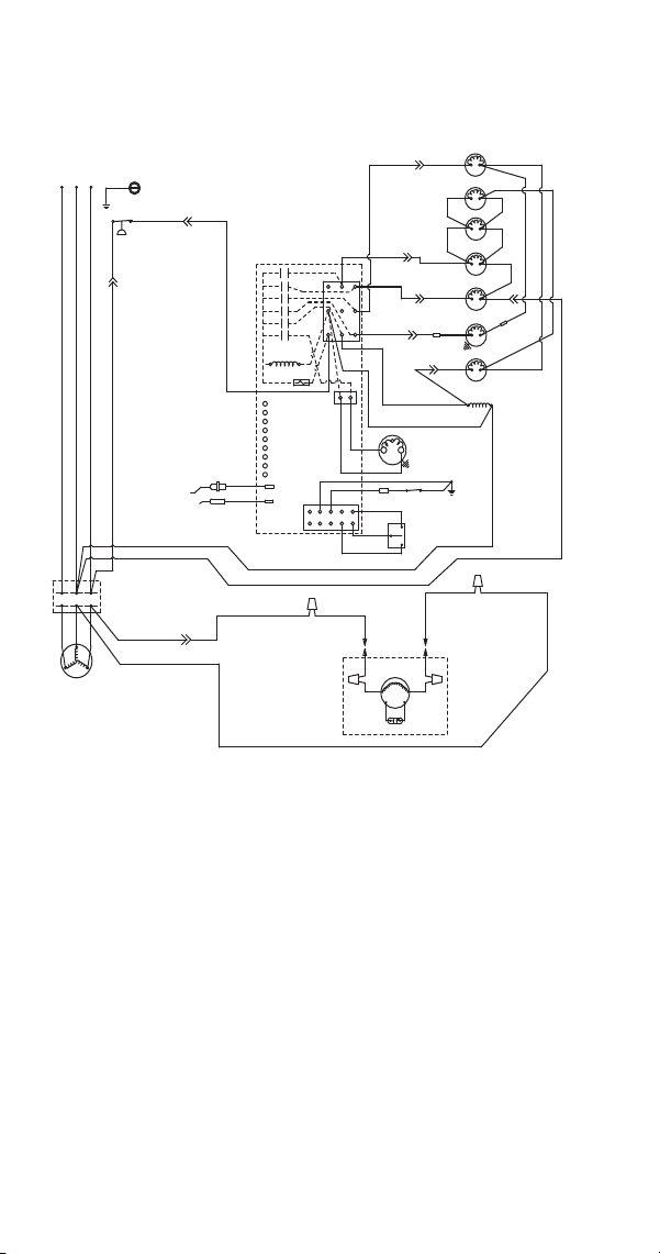
268 Part Number 8014793 6/18
S1400/S1600/S1800 -
Remote - 3 Phase
(42)
ICE THICKNESS
PROBE
WATER LEVEL
PROBE
HIGH PRESSURE
CUTOUT
(89)
(88)
T3
L2
L3
COMPRESSOR
T1
T2
CONTACTS
CONTACTOR
L1
L2
L3
L1
CLEAN
OFF
ICE
BIN
SWITCH
LOW D.C.
VOLTAGE
PLUG
CONTACTOR
COIL
(56)
(74)
(58)
FUSE (7A)
TRANS.
SOLENOID
(57)
DUMP
(76)
RH HARVEST
SOLENOID
(88)
(60)
(61)
(7)
(2)
(1)
(6)
(5)
(55)
(59)
CLEAN
LEFT BIN
RIGHT BIN
RMT BIN
WTR PROBE
ICE PROBE
HARV
SL-1
SL-2
AIR
PUMP
WHEN USED
(6)
(2)
(1)
(25)
(26)
L2
AIR
PUMP
(9)
(8)
CONTROL BOARD
(4)
(83)
(51)
(F1)
FAN MOTOR
REMOTE
(F2)
REMOTE CONDENSER
RUN CAPACITOR
PUMP
WATER
(98)
(81)
(75)
(87)
HPR
SOLENOID
(22)
(82)
(78)
LIQUID
SOLENOID
(79)
WATER
VALVE
(21)
(20)
(99)
LH HARVEST
SOLENOID
(77)
(80)
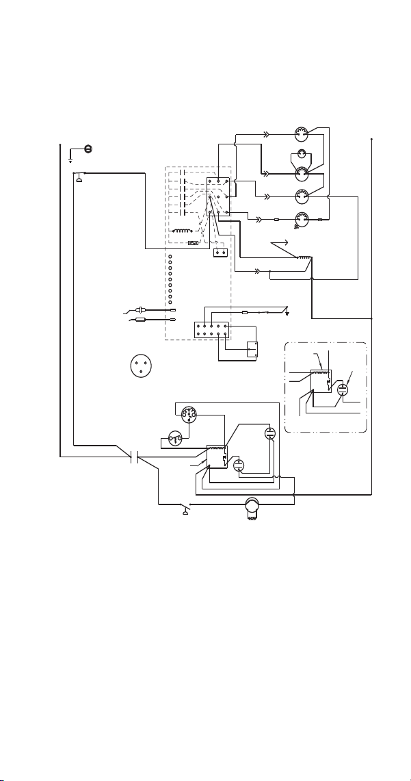
Part Number 8014793 6/18 269
WIRING DIAGRAMS FOR ENERGY EFFICIENT &
ENERGYSTAR MACHINES
S300/S420/S450/S500
Self-Contained - 1 Phase
Caution: Disconnect Power Before Working on Electrical Circuitry
L1
HIGH PRESSURE
CUTOUT
(89)
(88)
CONTROL BOARD
(2)
(6)
(1)
(5)
(7)
(4)
TRANS.
FUSE (7A)
(55)
(61)
CLEAN
ICE THICKNESS PROBE
WATER LEVEL PROBE
LEFT BIN
RIGHT BIN
RMT BIN
WTR PROBE
ICE PROBE
HARV
SL-1
SL-2
(9)
(8)
(56)
BIN SWITCH
(6)
LOW D.C.
VOLTAGE
PLUG
(1)
(2)
R
S
C
COMPRESSOR
TERMINAL LAYOUT
VIEWED FROM END
OF COMPRESSOR
COMPRESSOR
R
S
C
OVERLOAD INTERNAL
(230V 50/60 HZ)
(48)
(47)
(46)
CONTACTOR
CONTACTS
POTENTIAL
RELAY
(85)
FAN CYCLE CONTROL
RUN
CAPACITOR
(53)
(44)
START
CAPACITOR
(52)
(49)
(45)
FAN MOTOR
(AIR COOLED ONLY)
RUN CAPACITOR**
(50)
(48)
(47)
(46)
(50)
POTENTIAL
RELAY
4
1
5
2
4
1
5
2
(44)
START
CAPACITOR
(45)
(49)
WIRING FOR S300 ONLY
(NO RUN CAPACITOR)
CLEAN
OFF
ICE
TERMINATES AT
PIN CONNECTION
CONTACTOR
COIL
SEE SERIAL PLATE FOR VOLTAGE
(20)
(21)
WATER VALVE
AIR PUMP
WHEN USED
(22)
(28)
(99)
HARVEST
SOLENOID
(27)
DUMP
SOLENOID
(60)
(77)
WATER
PUMP
(76)
(80)
(81)
L2 OR N
(57)
(58)
(59)
(98)
(75)
(74)
(42)
L1
* - COMPRESSOR HAS
INTERNAL OVERLOAD
* * - SOME AIR COOLED MODELS
MAY NOT HAVE RUN CAPACITOR
ON FAN MOTOR
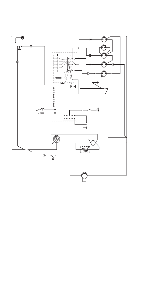
270 Part Number 8014793 6/18
S600/S850/S1000/S1200
Self-Contained - 1 Phase
Caution: Disconnect Power Before Working on Electrical Circuitry
L1
HIGH PRESSURE
CUTOUT
(89)
(88)
CONTROL BOARD
(2)
(6)
(1)
(5)
(7)
(4)
TRANS.
FUSE (7A)
(55)
(61)
CLEAN
ICE THICKNESS PROBE
WATER LEVEL PROBE
LEFT BIN
RIGHT BIN
RMT BIN
WTR PROBE
ICE PROBE
HARV
SL-1
SL-2
(9)
(8)
(56)
BIN SWITCH
(6)
LOW D.C.
VOLTAGE
PLUG
(1)
(2)
R
S
C
COMPRESSOR
*OVERLOAD
(51)
CONTACTOR
CONTACTS
FAN MOTOR
(AIR COOLED ONLY)
RUN
CAPACITOR
(RED)
(BLACK)
RUN CAPACITOR**
FAN CYCLE
CONTROL
(50)
(45)
CLEAN
OFF
ICE
CONTACTOR
COIL
SEE SERIAL PLATE FOR VOLTAGE
(20)
(21)
WATER VALVE
AIR PUMP
WHEN USED
(22)
(28)
(99)
HARVEST
SOLENOID
(27)
DUMP
SOLENOID
(60)
(77)
WATER
PUMP
(76)
(80)
(81)
L2 OR N
(57)
(58)
(59)
(98)
(75)
(74)
(42)
L1
* - COMPRESSOR HAS INTERNAL OVERLOAD
* * - SOME AIR COOLED MODELS MAY NOT HAVE
RUN CAPACITOR ON FAN MOTOR
(YELLOW)
(46)
R
R
(85)
(86)
TERMINATES AT
PIN CONNECTION
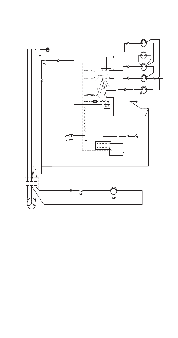
Part Number 8014793 6/18 271
S850/S1000/S1200
Self-Contained - 3 Phase
Caution: Disconnect Power Before Working on Electrical Circuitry
L1
HIGH PRESSURE
CUTOUT
(89)
(88)
CONTROL BOARD
(2)
(6)
(1)
(5)
(7)
(4)
TRANS.
FUSE (7A)
(55)
(61)
CLEAN
ICE THICKNESS PROBE
WATER LEVEL PROBE
LEFT BIN
RIGHT BIN
RMT BIN
WTR PROBE
ICE PROBE
HARV
SL-1
SL-2
(9)
(8)
(56)
BIN SWITCH
(6)
LOW D.C.
VOLTAGE
PLUG
(1)
(2)
COMPRESSOR
(51)
CONTACTOR
CONTACTS
FAN MOTOR
(AIR COOLED ONLY)
RUN CAPACITOR**
FAN CYCLE CONTROL
(85)
CLEAN
OFF
ICE
CONTACTOR
COIL
SEE SERIAL PLATE FOR VOLTAGE
(20)
(21)
WATER VALVE
AIR PUMP
WHEN USED
(22)
(28)
(99)
HARVEST
SOLENOID
(27)
DUMP
SOLENOID
(60)
(77)
WATER
PUMP
(76)
(80)
(81)
L2
(57)
(58)
(59)
(98)
(75)
(74)
(42)
L1
* * - SOME AIR COOLED MODELS MAY NOT HAVE RUN CAPACITOR ON FAN MOTOR
(86)
TERMINATES AT
PIN CONNECTION
L3
L2L3
T2
T3
T1
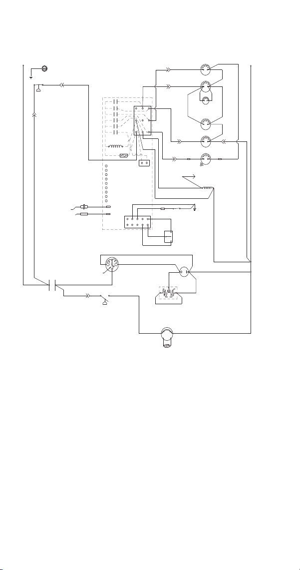
272 Part Number 8014793 6/18
S1400/S1800
Self-Contained - 1 Phase
(2)
(1)
R
S
CLEAN
OFF
ICE
RUN
CAPACITOR
(50)
(45)
R
(46)
3 TERMINAL PTCR
(AIR COOLED ONLY)
FAN MOTOR
RUN CAPACITOR**
(86)
(85)(51)
(BLACK)
*OVERLOAD
C
R
COMPRESSOR
(YELLOW)
(RED)
CONTACTOR
L1
CONTACTS
FAN CYCLE
CONTROL
(59)
CLEAN
LEFT BIN
RIGHT BIN
RMT BIN
WTR PROBE
ICE PROBE
HARVEST
SL-1
SL-2
(6)
L2
(9)
(8)
(42)
CONTROL BOARD
BIN
SWITCH
LOW D.C.
VOLTAGE
PLUG
CONTACTOR
COIL
(56)
TERMINATES AT
PIN CONNECTION
PUMP
WATER
(99)
(98)
(58)
FUSE (7A)
TRANS.
ICE THICKNESS
WATER LEVEL
SOLENOID
(57)
DUMP
(81)
(76)
LH HARVEST
SOLENOID
(87)
(77)
WATER
VALVE
(60)
(61)
(22)
(21)
(7)
(2)
(1)
(5)
HIGH PRESSURE
CUTOUT
(55)
L2 OR N
(88)
(20)
AIR
PUMP
(4)
(6)
RH HARVEST
SOLENOID
(80)
(88)
(74)
PROBE
PROBE
(75)
L1
(89)
(44)
(25) (26)
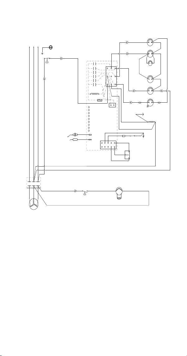
Part Number 8014793 6/18 273
S1400/S1800
Self-Contained - 3 Phase
(42)
CONTROL BOARD
CLEAN
OFF
ICE
BIN
SWITCH
(8)
LOW D.C.
VOLTAGE
PLUG
CONTACTOR
COIL
(56)
TERMINATES AT
PIN CONNECTION
(74)
PUMP
WATER
(58)
ICE THICKNESS
PROBE
WATER LEVEL
PROBE
SOLENOID
DUMP
(81)
(75)
(76)
LH HARVEST
SOLENOID
(87)
(77)
VALVE
WATER
(60)
(61)
(22)(21)
(7)
(2)
(1)
(6)
(5)
HIGH PRESSURE
CUTOUT
(55)
(89)
(88)
(20)
(59)
CLEAN
LEFT BIN
RIGHT BIN
RMT BIN
WTR PROBE
ICE PROBE
HARV
SL-1
SL-2
AIR
PUMP
(6)
(2)
(1)
(9)
(25)
(26)
L2
FAN CYCLE CONTROL
T3
L2
L3
COMPRESSOR
T1
T2
(51)
(85)
(86)
CONTACTS
CONTACTOR
L1
L2
L3
L1
(AIR COOLED ONLY)
FAN MOTOR
RUN CAPACITOR**
FUSE (7A)
TRANS.
(4)
(99)
(98)
(57)
RH HARVEST
SOLENOID
(80)
(88)
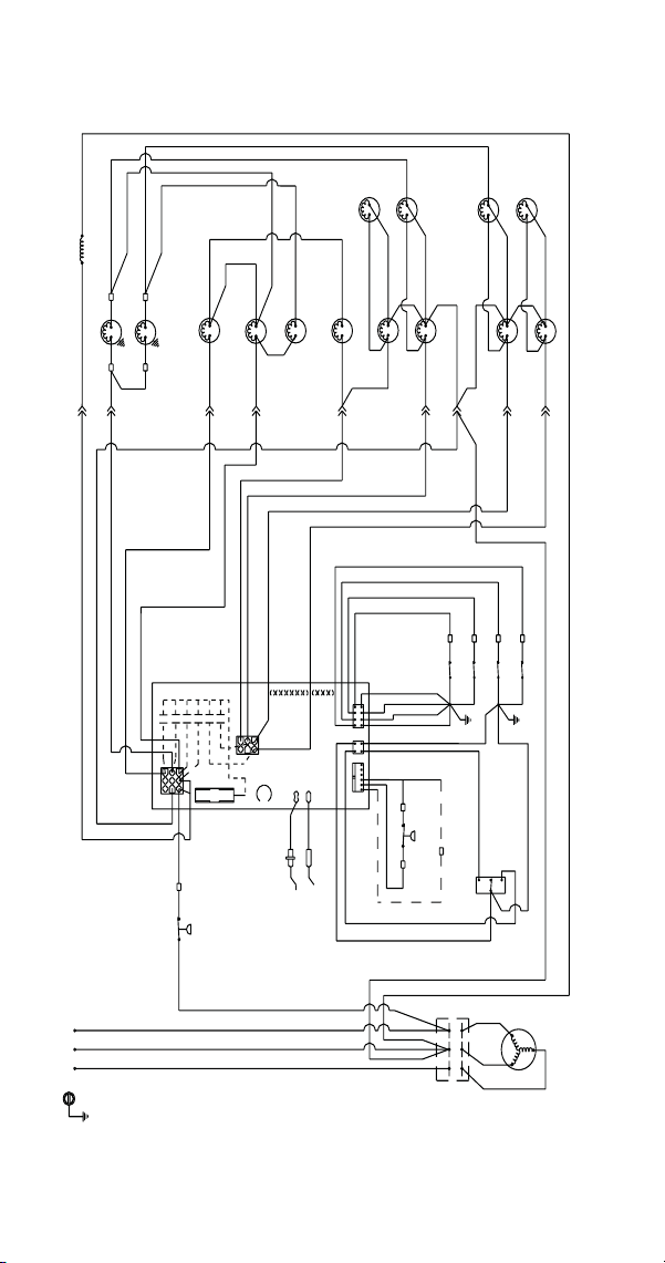
274 Part Number 8014793 6/18
S3300
Water-Cooled - 3 phase
AIR
PUMP
4
AIR
PUMP
3
AIR
PUMP
2
AIR
PUMP
1
HARVEST
SOLENOID 4
HARVEST
SOLENOID 3
HARVEST
SOLENOID 2
HARVEST
SOLENOID 1
(71)
(71)
(72)
(72)
(82)
(82)
(73)
(74A)
(74)
(74B)
(73)
HARVEST PRES
SOLENOID
DUMP
SOLENOID 1
DUMP
SOLENOID 2
(76B)
(76A)
(21)
WATER FILL
SOLENOID
WATER
PUMP 2
WATER
PUMP 1
(98B)
(98A)
CONTACTOR
COIL
(84)
(56)
(57)
(64)
(20)
(60)
(63)
(62)
(61)
2
(4)
1
3
4
5
6
(3)
(2)
(1)
CLN
HARV
WTR LEV
WFS
LIQ SOL
DUMP
PUMP
CS2
HG2
CS1
HG1
(22)
(23)
(75)
CURTAIN SWITCH 1
CURTAIN SWITCH 2
CURTAIN SWITCH 3
CURTAIN SWITCH 4
(24)
(19)
CLEAN
OFF
ICE
* OPTIONAL
BIN THERMO
SWITCH
LOW PRES
SWITCH
(20)
WATER LEVEL PROBE
ICE THICKNESS PROBE
HIGH PRES
CUTOUT
(55)
GROUND
SEE SERIAL PLATE FOR VOLTAGE
L3
L2 L1
L3
L2
L1
CONTACTOR
CONTACTS
T3
T1
T2
COMPRESSOR
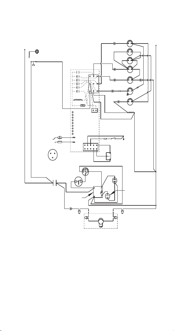
Part Number 8014793 6/18 275
S500
Remote - 1 Phase
Caution: Disconnect Power Before Working on Electrical Circuitry
L1
HIGH PRESSURE
CUTOUT
(89)
(88)
CONTROL BOARD
(2)
(6)
(1)
(5)
(7)
(4)
TRANS.
FUSE (7A)
(61)
CLEAN
ICE THICKNESS PROBE
WATER LEVEL PROBE
LEFT BIN
RIGHT BIN
RMT BIN
WTR PROBE
ICE PROBE
HARV
SL-1
SL-2
(9)
(8)
(56)
BIN SWITCH
(6)
LOW D.C.
VOLTAGE
PLUG
(1)
(2)
R
S
C
COMPRESSOR
TERMINAL LAYOUT
VIEWED FROM END
OF COMPRESSOR
COMPRESSOR
R
S
C
OVERLOAD INTERNAL
(230V 50/60 HZ)
(48)
(47)
(46)
CONTACTOR
CONTACTS
POTENTIAL
RELAY
(86)
REMOTE CONDENSER
RUN
CAPACITOR
(53)
(44)
START
CAPACITOR
(52)
(49)
(45)
REMOTE
FAN MOTOR
RUN CAPACITOR
(51)
(50)
4
1
5
2
(F1)
(F2)
CLEAN
OFF
ICE
CONTACTOR
COIL
SEE SERIAL PLATE FOR VOLTAGE
(20)
(21)
WATER VALVE
AIR PUMP
WHEN USED
(22)
(28)
(99)
HARVEST
SOLENOID
(27)
DUMP
SOLENOID
(60)
(77)
WATER
PUMP
(76)
(80)
(81)
L2 OR N
(57)
(58)
(59)
(98)
(75)
(74)
(42)
L1
* - COMPRESSOR HAS INTERNAL OVERLOAD
* * - SOME AIR COOLED MODELS MAY NOT HAVE
RUN CAPACITOR ON FAN MOTOR
(78)
(79)
(82)
LIQUID LINE
SOLENOID
(83)
HPR
SOLENOID
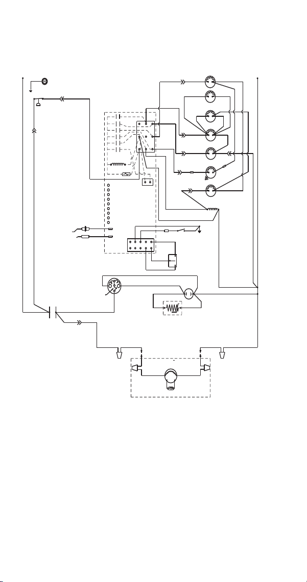
276 Part Number 8014793 6/18
S600/S850/S1000/S1200
Remote - 1 Phase
Caution: Disconnect Power Before Working on Electrical Circuitry
L1
HIGH PRESSURE
CUTOUT
(89)
(88)
CONTROL BOARD
(2)
(6)
(1)
(5)
(7)
(4)
TRANS.
FUSE (7A)
(55)
(61)
CLEAN
ICE THICKNESS PROBE
WATER LEVEL PROBE
LEFT BIN
RIGHT BIN
RMT BIN
WTR PROBE
ICE PROBE
HARV
SL-1
SL-2
(9)
(8)
(56)
BIN SWITCH
(6)
LOW D.C.
VOLTAGE
PLUG
(1)
(2)
R
S
C
COMPRESSOR
*OVERLOAD
(51)
CONTACTOR
CONTACTS
REMOTE
FAN MOTOR
RUN
CAPACITOR
(RED)
(BLACK)
RUN CAPACITOR
(F1)
(50)
(45)
CLEAN
OFF
ICE
CONTACTOR
COIL
SEE SERIAL PLATE FOR VOLTAGE
(20)
(21)
WATER VALVE
AIR PUMP
WHEN USED
(22)
(28)
(99)
HARVEST
SOLENOID
(27)
DUMP
SOLENOID
(60)
(77)
WATER
PUMP
(76)
(80)
(81)
L2 OR N
(57)
(58)
(59)
(98)
(75)
(74)
(42)
L1
(YELLOW)
(46)
R
R
REMOTE CONDENSER
(F2)
(83)
LIQUID
SOLENOID
HPR
SOLENOID
(78)
(82)
(79)
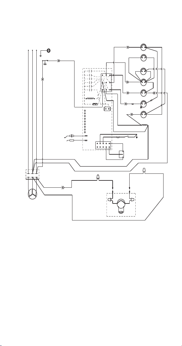
Part Number 8014793 6/18 277
S850/S1000/S1200
Remote - 3 Phase
Caution: Disconnect Power Before Working on Electrical Circuitry
L1
HIGH PRESSURE
CUTOUT
(89)
(88)
CONTROL BOARD
(2)
(6)
(1)
(5)
(7)
(4)
TRANS.
FUSE (7A)
(55)
(61)
CLEAN
ICE THICKNESS PROBE
WATER LEVEL PROBE
LEFT BIN
RIGHT BIN
RMT BIN
WTR PROBE
ICE PROBE
HARV
SL-1
SL-2
(9)
(8)
(56)
BIN SWITCH
(6)
LOW D.C.
VOLTAGE
PLUG
(1)
(2)
COMPRESSOR
(51)
CONTACTOR
CONTACTS
REMOTE
FAN MOTOR
RUN CAPACITOR**
REMOTE CONDENSER
CLEAN
OFF
ICE
CONTACTOR
COIL
SEE SERIAL PLATE FOR VOLTAGE
(20)
(21)
WATER VALVE
AIR PUMP
WHEN USED
(22)
(28)
(99)
HARVEST
SOLENOID
(27)
DUMP
SOLENOID
(60)
(77)
WATER
PUMP
(76)
(80)
(81)
L2
(57)
(58)
(59)
(98)
(75)
(74)
(42)
L1
* - COMPRESSOR HAS INTERNAL OVERLOAD
* * - SOME AIR COOLED MODELS MAY NOT HAVE RUN CAPACITOR ON FAN MOTOR
L3
L2
L3
T2
T3
T1
(79)
(78)
HPR
SOLENOID
LIQUID
SOLENOID
(83)
(82)
(F2)
(F1)
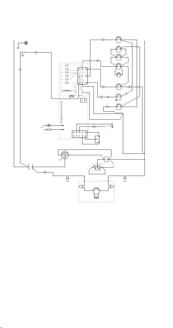
278 Part Number 8014793 6/18
S1400/S1800
Remote - 1 Phase
(59)
CLEAN
LEFT BIN
RIGHT BIN
RMT BIN
WTR PROBE
ICE PROBE
HARV
SL-1
SL-2
(6)
(2)
(1)
(25)
(26)
L2
(9)
(8)
(42)
CONTROL BOARD
S
(79)
(51)
CLEAN
OFF
ICE
RUN
CAPACITOR
(50)
REMOTE
FAN MOTOR
RUN CAPACITOR
(F2)
(F1)
(BLACK)
*OVERLOAD
C
R
COMPRESSOR
(YELLOW)
(RED)
CONTACTOR
L1
BIN
SWITCH
LOW D.C.
VOLTAGE
PLUG
CONTACTOR
COIL
(56)
(74)
WATER
PUMP
(98)
(58)
FUSE (7A)
TRANS.
ICE THICKNESS
PROBE
WATER LEVEL
PROBE
(57)
DUMP
SOLENOID
(81)
(75)
(76)
RH HARVEST
SOLENOID
(87)
(88)
HPR
SOLENOID
(60)
(61)
(22)
(82)
(7)
(2)
(1)
(6)
(5)
HIGH PRESSURE
CUTOUT
(55)
L2 OR N
CONTACTS
(89)
(88)
(78)
AIR
PUMP
(4)
LIQUID
SOLENOID
(83)
REMOTE CONDENSER
WATER
VALVE
(21)
(20)
(99)
LH HARVEST
SOLENOID
(80)
(77)
L1
(46)
(44)
(45)
R
R
3 TERMINAL
PTCR
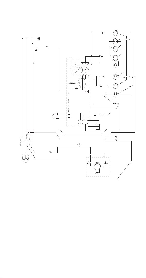
Part Number 8014793 6/18 279
S1400/S1800
Remote - 3 Phase
(42)
ICE THICKNESS
PROBE
WATER LEVEL
PROBE
HIGH PRESSURE
CUTOUT
(89)
(88)
T3
L2
L3
COMPRESSOR
T1
T2
CONTACTS
CONTACTOR
L1
L2
L3
L1
CLEAN
OFF
ICE
BIN
SWITCH
LOW D.C.
VOLTAGE
PLUG
CONTACTOR
COIL
(56)
(74)
(58)
FUSE (7A)
TRANS.
SOLENOID
(57)
DUMP
(76)
RH HARVEST
SOLENOID
(88)
(60)
(61)
(7)
(2)
(1)
(6)
(5)
(55)
(59)
CLEAN
LEFT BIN
RIGHT BIN
RMT BIN
WTR PROBE
ICE PROBE
HARV
SL-1
SL-2
AIR
PUMP
(6)
(2)
(1)
(25)
(26)
L2
(9)
(8)
CONTROL BOARD
(4)
(83)
(51)
(F1)
FAN MOTOR
REMOTE
(F2)
REMOTE CONDENSER
RUN CAPACITOR
PUMP
WATER
(98)
(81)
(75)
(87)
HPR
SOLENOID
(22)
(82)
(78)
LIQUID
SOLENOID
(79)
WATER
VALVE
(21)
(20)
(99)
LH HARVEST
SOLENOID
(77)
(80)
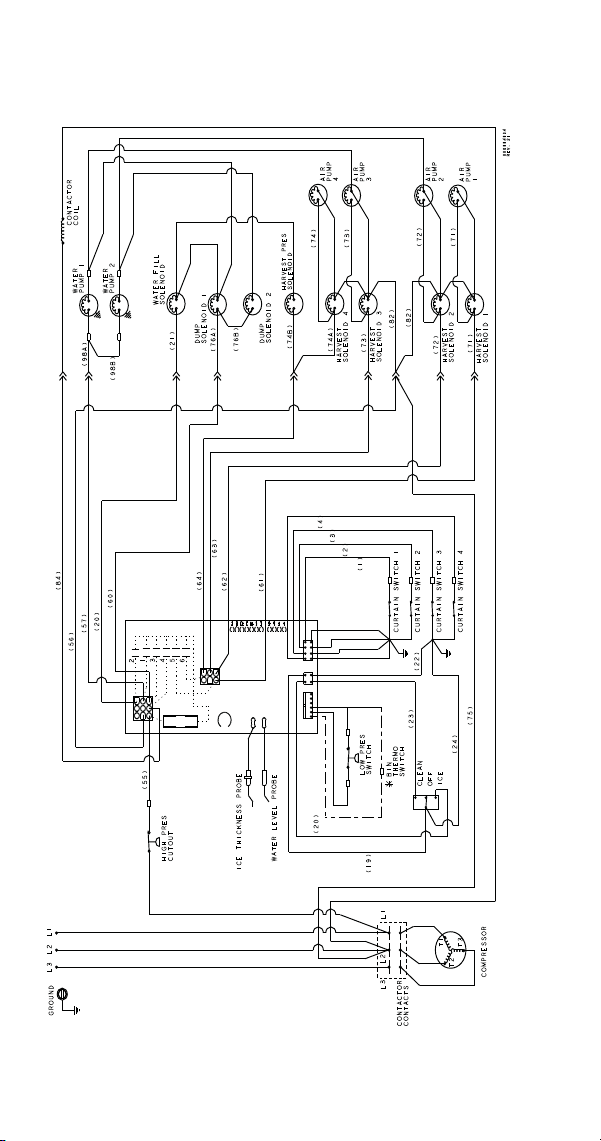
280 Part Number 8014793 6/18
ST3000W
Self-Contained - 3 Phase
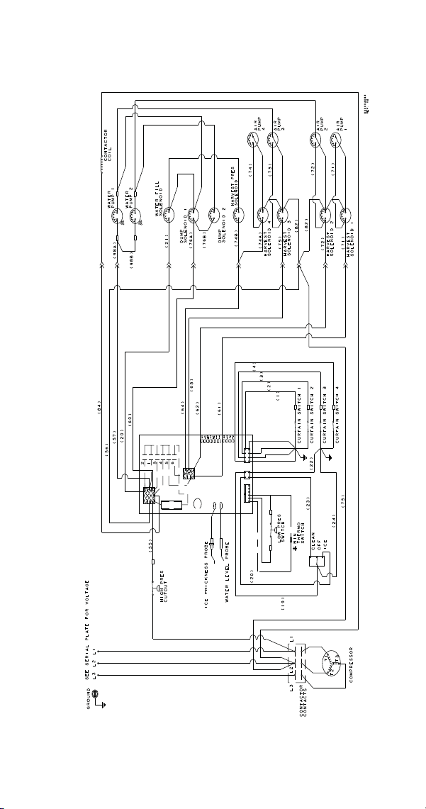
Part Number 8014793 6/18 281
S3300W
Self-Contained - 3 Phase
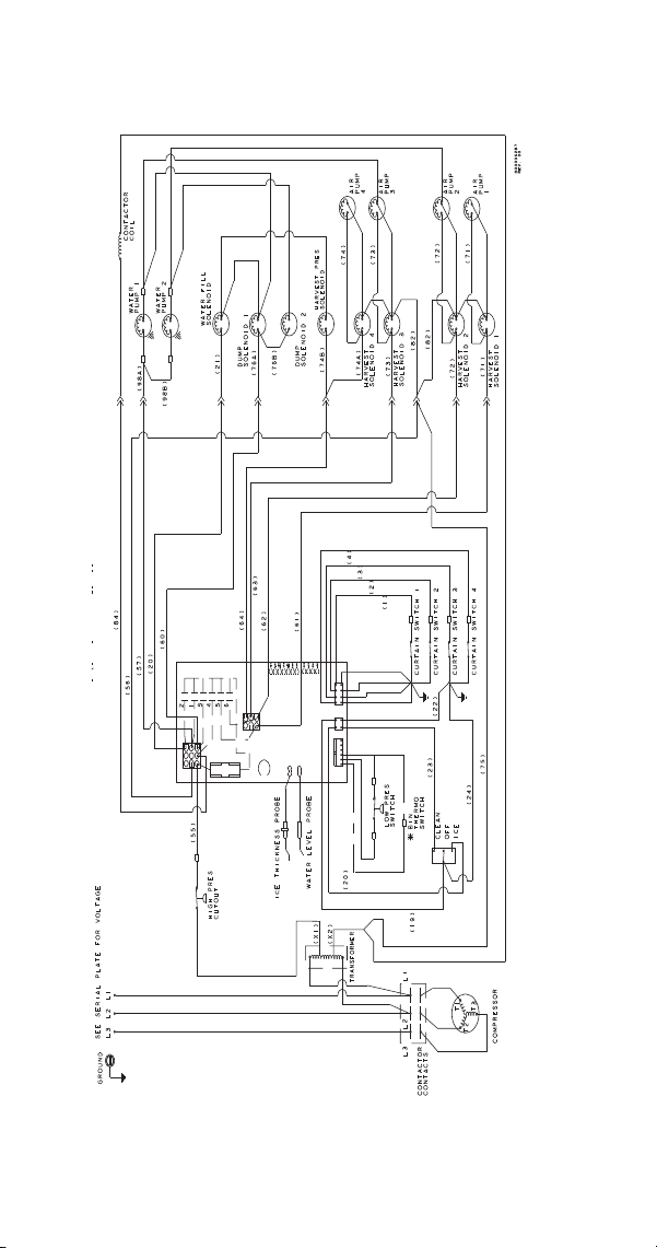
282 Part Number 8014793 6/18
S3300WM Marine
Self-Contained - 3 Phase
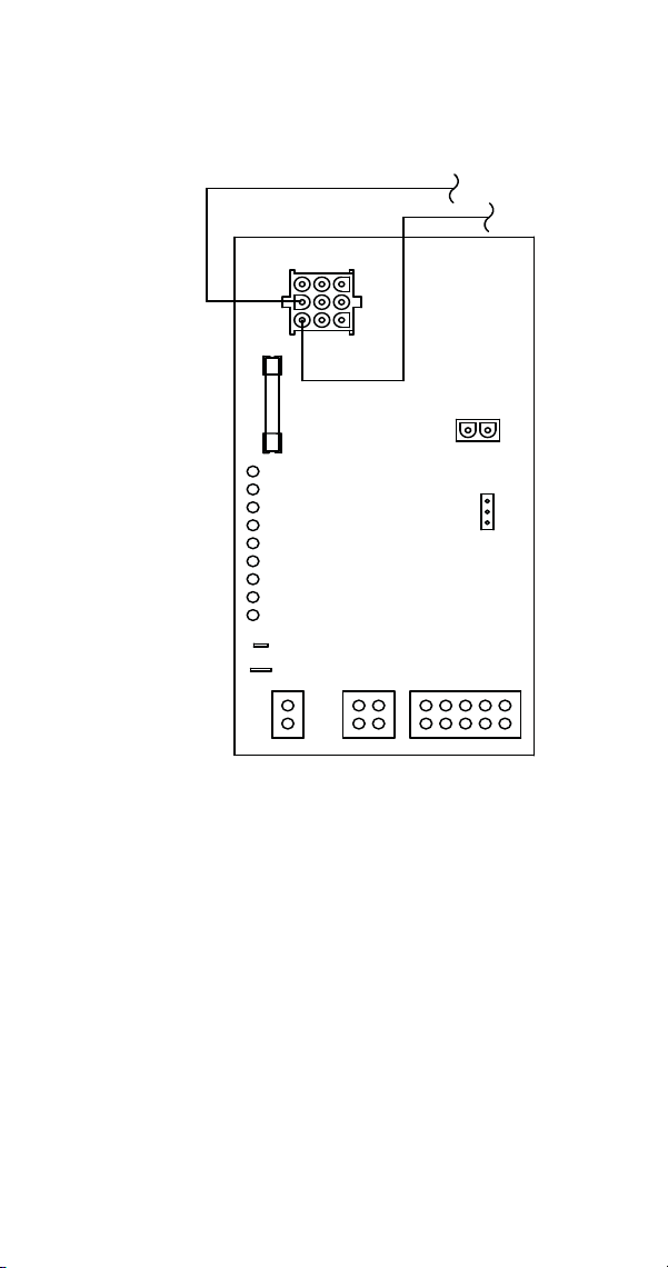
Part Number 8014793 6/18 283
Electronic Control Board
Single and Twin Evaporator Without Test Button
N 115V
L2 208-230V
PRIMARY POWER
SUPPLY
AC LINE VOLTAGE
ELECTRICAL PLUG
MAIN FUSE
(7A)
AIR PUMP
(NOT USED ON
ALL MODELS)
WATER PURGE
ADJUSTMENT
CLEAN LIGHT (YELLOW)
LEFT BIN LIGHT (GREEN)
RIGHT BIN LIGHT (GREEN)
REMOTE BIN LIGHT (NOT USED)
WATER PROBE LIGHT (GREEN)
ICE PROBE LIGHT (GREEN)
HARVEST LIGHT (RED)
SAFETY LIMIT 1 LIGHT (RED)
SAFETY LIMIT 2 LIGHT (RED)
ICE THICKNESS PROBE
(3/16" CONNECTION)
WATER LEVEL PROBE
REMOTE BIN
AUTOMATIC CLEANING
SYSTEM PLUG
(AuCS)
DC LOW VOLTAGE
ELECTRICAL PLUG
{BIN SWITCH(ES)&
TOGGLE SWITCH}
(56)
(55)
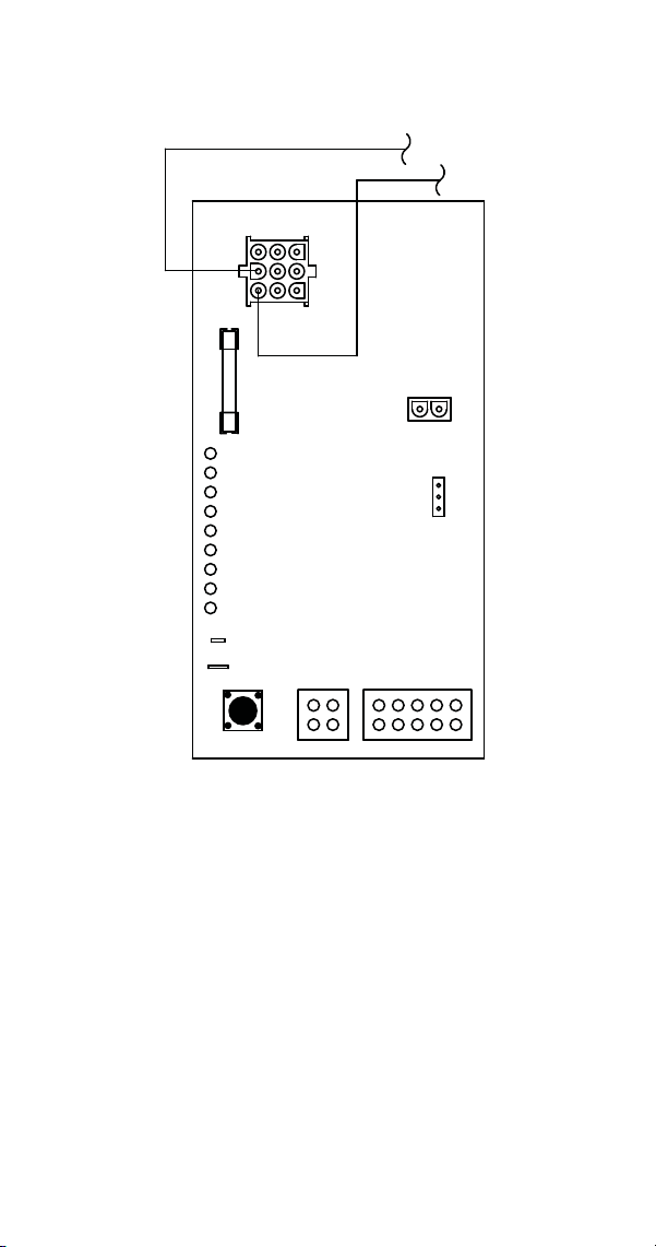
284 Part Number 8014793 6/18
Single and Twin Evaporator With Test Button
N 115V
L2 208-230V
PRIMARY POWER
SUPPLY
AC LINE VOLTAGE
ELECTRICAL PLUG
MAIN FUSE
(7A)
AIR COMPRESSOR
(NOT USED ON
ALL MODELS)
WATER PURGE
ADJUSTMENT
CLEAN LIGHT (YELLOW)
LEFT BIN LIGHT (GREEN)
RIGHT BIN LIGHT (GREEN)
REMOTE BIN LIGHT (GREEN)
WATER PROBE LIGHT (GREEN)
ICE PROBE LIGHT (GREEN)
HARVEST LIGHT (RED)
SAFETY LIMIT 1 LIGHT (RED)
SAFETY LIMIT 2 LIGHT (RED)
ICE THICKNESS PROBE
(3/16" CONNECTION)
WATER LEVEL PROBE
AUTOMATIC CLEANING
SYSTEM PLUG
(AuCS)
DC LOW VOLTAGE
ELECTRICAL PLUG
{BIN SWITCH(ES)&
TOGGLE SWITCH}
(56)
(55)
SERVICE
MODE
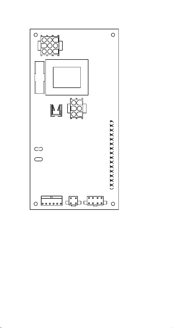
Part Number 8014793 6/18 285
Quad Evaporator Ice Machines
ICE PROBE
WATER LEVEL PROBE
HARVEST VALVES
FUSE 7A
CLEAN (YELLOW)
HARVEST (RED)
WATER LEVEL (GREEN)
WATER SOLENOID (RED)
LIQUID SOLENOID (RED)
DUMP VALVE (RED)
WATER PUMP (RED)
CURTAIN SWITCH 4 (GREEN)
CURTAIN SWITCH 3 (GREEN)
CURTAIN SWITCH 2 (GREEN)
CURTAIN SWITCH 1 (GREEN)
HARVEST VALVE 1 (RED)
HARVEST VALVE 2 (RED)
HARVEST VALVE 3 (RED)
HARVEST VALVE 4 (RED)
CURTAIN SWITCHES
TOGGLE
SWITCH
LOW PRESSURE SWITCH
&
OPTIONAL BIN THERMOSTAT
AC LINE
VOLTAGE PLUG
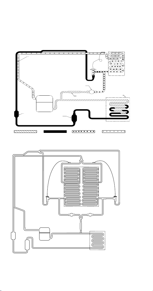
286 Part Number 8014793 6/18
Refrigeration Tubing Schematics
SELF-CONTAINED AIR- OR
WATER -COOLED MODELS
S300/S320/S420/S450/S500/S600/S850/S1000/S1200
S1400/S1600/S1800
HEAT
EXCHANGER
EVAPORATOR
CONDENSER
COMPRESSOR
HOT GAS SOLENOID VALVE
AIR OR WATER
DRIER
STRAINER
RECEIVER
(WATER COOLED ONLY)
LOW PRESSURE VAPORLOW PRESSURE LIQUIDHIGH PRESSURE LIQUIDHIGH PRESSURE VAPOR
X
EXPANSION
VALV E
x
x
CONDENSER
COMPRESSOR
HEAT
EXCHANGER
RECEIVER
DRIER
EVAPORATOR
HARVEST
SOLENOID VALVE
STRAINER
HARVEST
SOLENOID VALVE
EXPANSION
VALVE
EXPANSION
VALVE
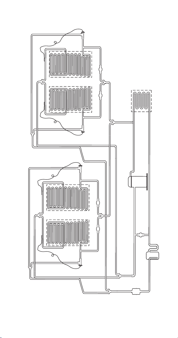
Part Number 8014793 6/18 287
ST3000W/S3300W
x
x
x
x
x
EVAPORATOR 1
EVAPORATOR 2
EVAPORATOR 3 EVAPORATOR 4
WATER-COOLED
CONDENSER
SCROLL
COMPRESSOR
RECEIVER
HARVEST PRESSURE
SOLENOID VALVE
HARVEST SOLENOID
VALVE
HARVEST SOLENOID
VALVE
HARVEST SOLENOID
VALVE
HARVEST SOLENOID
VALVE
EXPANSION
VALVE
EXPANSION
VALVE
EXPANSION
VALVE
EXPANSION
VALVE
HEAT
EXCHANGER
HEAT
EXCHANGER
DRIER
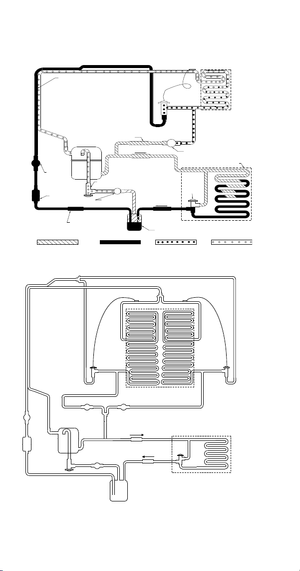
288 Part Number 8014793 6/18
REMOTE MODELS
S500/S600/S850/S1000
S1400/S1600/S1800
X
X
HEAT
EXCHANGER
EVAPORATOR
SOLENOID
LINE
LIQUID
CHECK VALVE
SERVICE
RECEIVER
CONDENSER
REMOTE
COMPRESSOR
RECEIVER
EXPANSION
VALV E
HOT GAS SOLENOID VALVE
VALV E
HARVEST PRESSURE
REGULATING VALVE
H.P.R. SOLENOID
VALV E
VALV E
CHECK VALVE
DRIER
STRAINER
HEAD
PRESSURE
CONTROL
VALVE
B
R
C
HIGH PRESSURE VAPOR HIGH PRESSURE LIQUID
LOW PRESSURE LIQUID
LOW PRESSURE VAPOR
x
x
x
REMOTE
CONDENSER
COMPRESSOR
HEAT
EXCHANGER
RECEIVER
DRIER
EXPANSION
VALVE
EVAPORATOR
HPR VALVE
LLSV
CHECK VALVE
CHECK VALVE
HARVEST
SOLENOID VALVE
STRAINER
HARVEST
SOLENOID VALVE
HEAD
PRESSURE
CONTROL
VALVE
EXPANSION
VALVE


P
art Number 8014793 6/18
M
ANITOWOC ICE
2110 SOUTH 26TH STREET
MANITOWOC, WI 54220
800-545-5720
WWW.MANITOWOCICE.COM
©2018 Manitowoc I
ce except where explicitly stated. All rights reserved.