
Technical Support and E-Warranty Certificate
www.vevor.com/support
MORTISING ATTACHMENT KIT
INSTRUCTIONS
MODEL:DPA65
We continue to be committed to provide you tools with competitive price.
"Save Half", "Half Price" or any other similar expressions used by us only represents an
estimate of savings you might benefit from buying certain tools with us compared to the major
top brands and does not necessarily mean to cover all categories of tools offered by us. You
are kindly reminded to verify carefully when you are placing an order with us if you are
actually saving half in comparison with the top major brands.

- 1 -
MODEL:DPA65
Have product questions? Need technical support? Please feel free to
contact us:
Technical Support and E-Warranty Certificate
www.vevor.com/support
NEED HELP? CONTACT US!
This is the original instruction, please read all manual instructions
carefully before operating. VEVOR reserves a clear interpretation of our
user manual. The appearance of the product shall be subject to the
product you received. Please forgive us that we won't inform you again if
there are any technology or software updates on our product.
MORTISING ATTACHMENT KIT
- 2 -
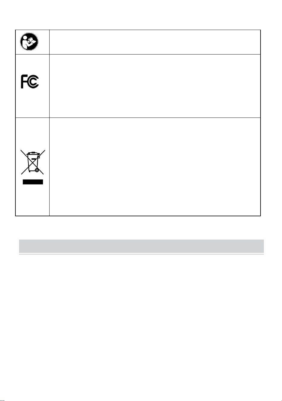
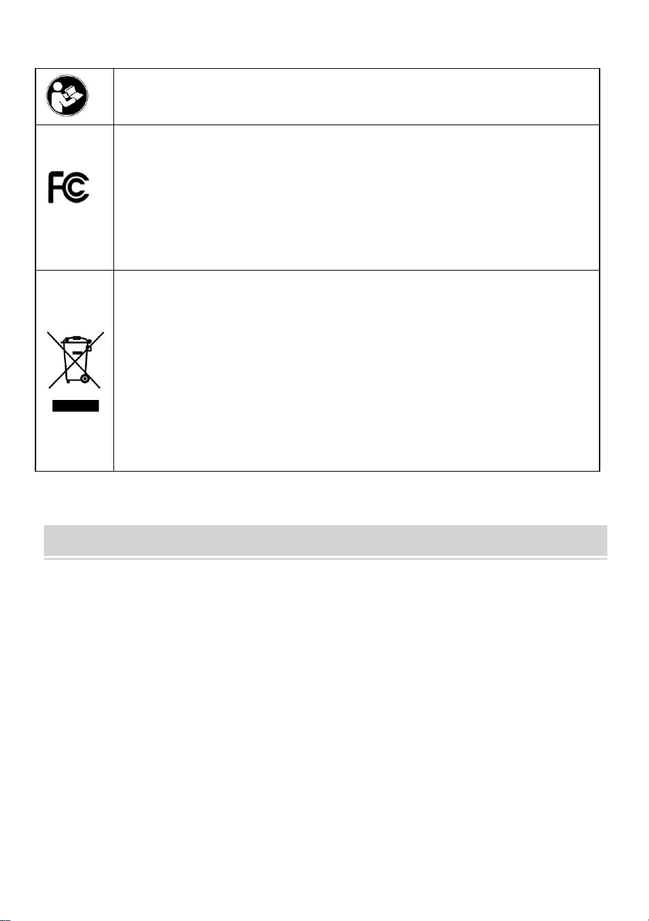
Warning-To reduce the risk of injury, user must read
instructions manual carefully.
This device complies with Part 15 of the FCC Rules. Operation
is subject to the following two conditions:(1)This device may
not cause harmful interference, and (2)this device must accept
any interference received, including interference that may
cause undesired operation.
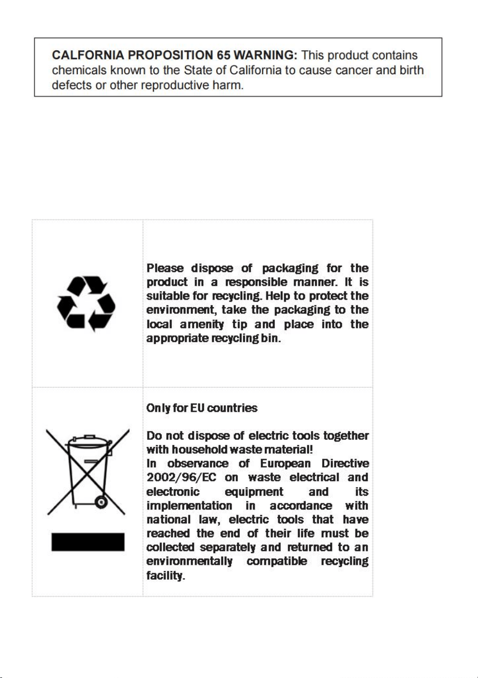
This product is subject to the provision of European Directive
2012/19/EC. The symbol showing a wheelie bin crossed
through indicates that the product requires separate refuse
collection in the European Union. This applies to the product
and all accessories marked with this symbol. Products marked
as such may not be discarded with normal domestic waste, but
must be taken to a collection point for recycling electrical and
electronic devices
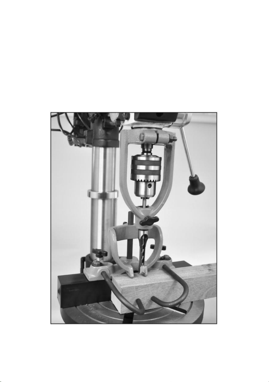
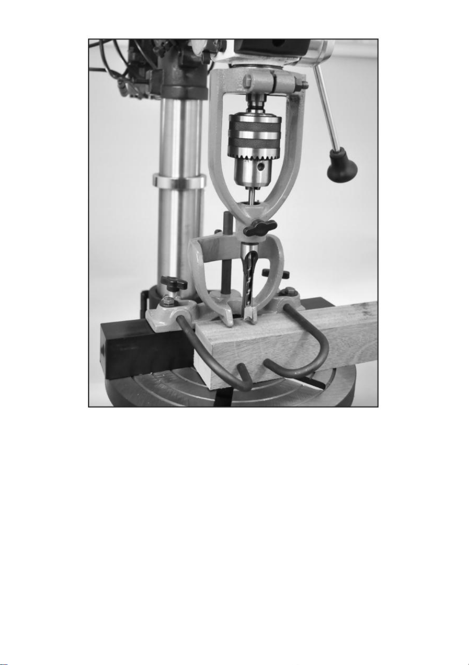
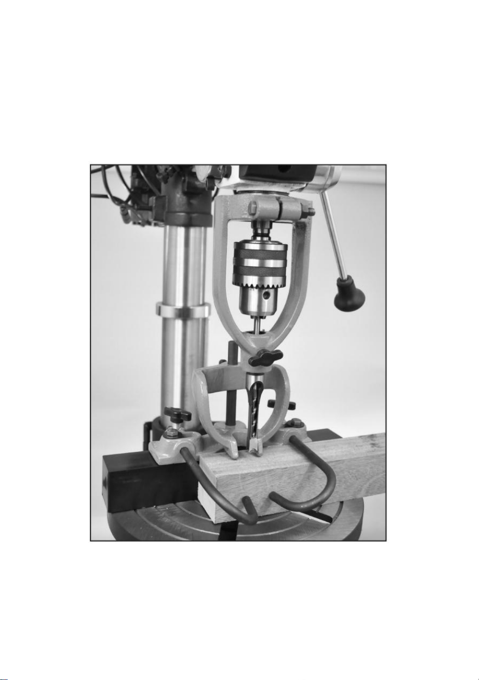
INTRODUCTION
The Mortising Attachment converts your Drill Press in to an accurate
mortising
machine. It is ideal for drilling square holes for mortise & tenon joints that
are commonly used in furniture, cabinets, sash, pattern shops and other
woodworking plants.
The Mortising Attachment Kit can be installed on most any drill press with
a collar
size of: 52.5mm, 55mm, 60mm, or 65mm.
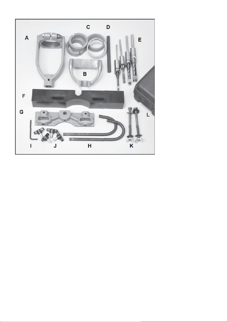
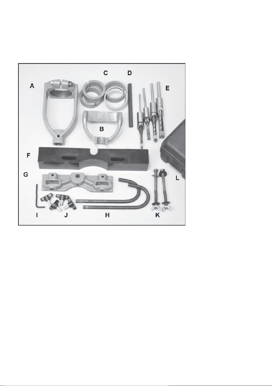
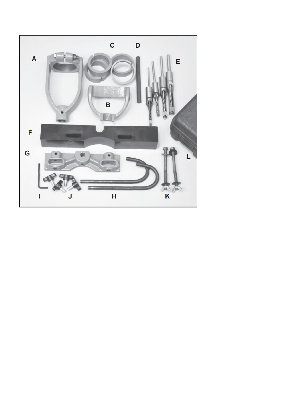
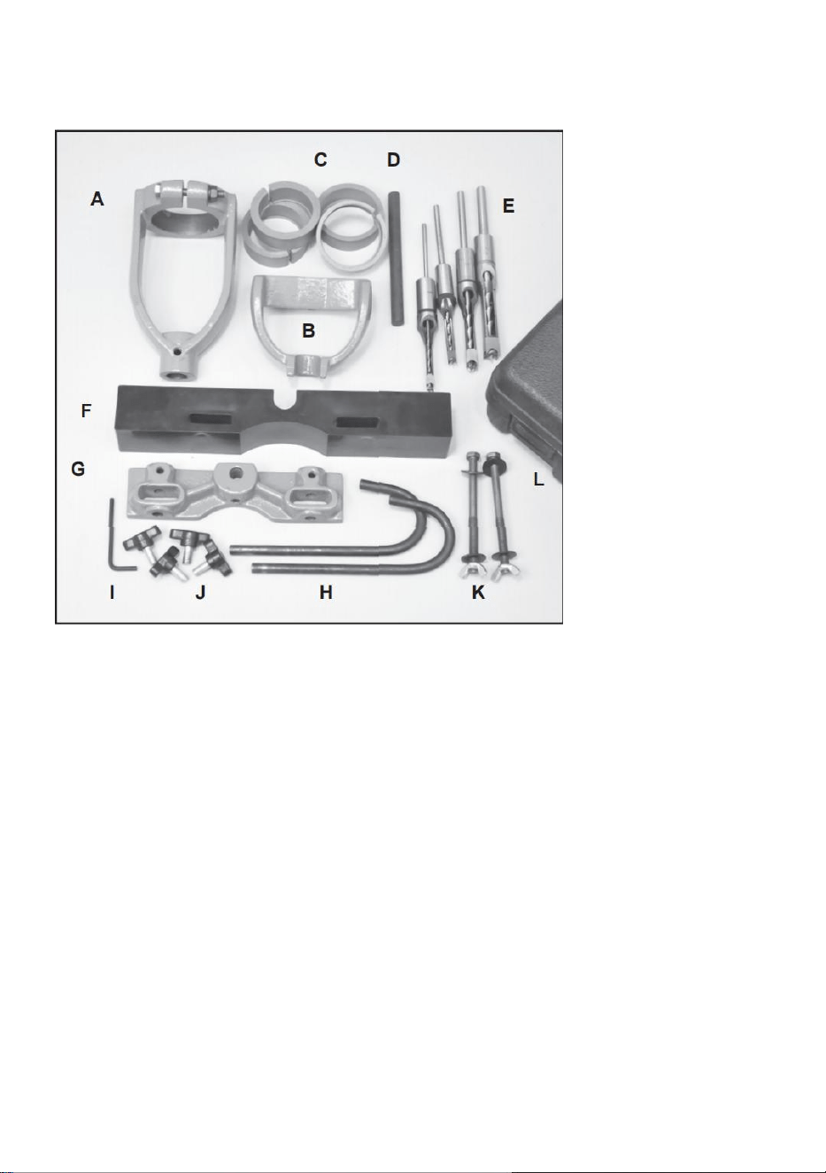
The name of the kit inventory.
- 3 -
A. Chisel Holder Assembly *1
B. Hold Down Bracke *1
C. Bushings *4
D. Hold Down Rod *1
E. Chisels & Drill Bits (1/4, 5/8, 3/8, 1/2) *4
F. Fence *1
G. Rod Holding Casting *1
H. Curved Guide Rods *1
I. Hex Wrench 4mm *1
J. Large Wing Nuts *4
K. 5/16-18 x 4 Hex Bolts *2
Washers *4 Wing Nuts *2
L. Carry Case with *1
M. Instructions (not shown) *1

- 4 -
INSTALLATION INSTRUCTIONS
MOUNTING ON THE DRILL PRESS TABLE.
We recommend installing a 1/2, plywood panel on the drill press table.
It can be held in place by inserting it under the mortising fence. Drill
holes in the plywood to match the slots in the table. The plywood will
prevent damage to the the mortising chisel and drill bit if it should
strike the metal drill press table by accident. It is also a simple way to
increase the size of the drill press table to hold your projects.
MOUNTING THE CHISEL HOLDER.
1. Mount the Chisel Holder (A) onto, or just above the base of the Drill
Press quill, with the holder’s fastening bolt facing outward, away from
the drill press column. For a proper fit, a Bushing (C) may be required
to be inserted within the chisel holder’s top collar.
2. Once installed, tighten the nut and bolt on the chisel holder to keep the
attachment from slipping.
Install mortise and tenon chisels and drill bits.
1. Four sizes of Hollow Chisel Mortising Chisels and Bits (E) are included
with the kit - 1/4”, 5/8”, 3/8” and 1/2”. Use only the correct combination of
the chisels with their corresponding bit. These tools are
supplied factory ground, and MUST be sharpened before use. If either
one is dull, there will be excessive friction with heat build-up, which
will make the drilling operation difficult and damage the tools. Consult
woodworking books or magazine articles on the proper techniques to
putting sharp edges on these items.

- 5 -
2. No bushings are required to install the drill bit shanks into the chisel
holder’s collar, as they both have the same diameter. The shank of the
chisel will be held by the drill press keyed chuck, just as a normal drill bit
would be held.
INSTALLING THE BIT AND CHISEL.
1. Insert the drill bit through the chisel and into the drill press’ keyed
chuck. Hand tighten the chuck only.
2. Insert the chisel into the chisel holder, and secure it in place with the
wing nut. NOTE: Clamp the chisel so that its shoulder is about
1/32” below the bottom of the holder.
3. Push the drill bit up into the drill chuck as far as it will go, and fasten it in
place with the chuck key. The end of the drill bit should be up against the
end of the square chisel.
4. Loosen the wing nut securing the chisel and move the chisel upward to
take up the 1/32” space previously left in Step 2. Tighten the chisel in
place. This method assures that there is proper clearance between the
cutting lips of the drill bit and the points of the chisel.
When in use, the square chisel will cut into the wood, forcing the cut
material inwards. The drill bit then cuts out the center of the hole and
directs the chisel cut material up out of the hole in a single motion.
The Hex Bolts (K) supplied with the Kit are long enough to go through
the hold down bracket, fence, plywood and drill press table. Insert the
hex bolt through the slots in each. Use washers under the hex head bolt,
and under the wing nut to distribute the holding pressure.
ASSEMBLE THE HOLD DOWN BRACKE.
1. Insert the Hold Down Rod (D) into the center hole of the Rod Holding
Casting (G), and secure it in place with the Hex Screw. A 4mm Hex
Wrench (I) is supplied for this.
2. Slide the Hold Down Bracket (B) down onto the hold down rod. The hold
down can be adjusted up and down on the rod as needed to apply slight
pressure down onto your work that is being drilled. This bracket will keep
your project held down when the mortising chisel & bit are released and
- 6 -
pulled out of the hole that they were drilling.
INSTALL THE CURVED GUIDE ROD.
1. Insert the two Curved Guide Rods (H) into the horizontal holes that are
on either side of the rod holding casting, and secure them in postion with
the supplied wing nuts.
2. The guide rods should be positioned on the front face of your work, so
that they put pressure against the wood and push your project against
the fence.
Schematic diagram of the finished assembly

- 7 -
SET UP.
1. Place your work piece on the drill press table and adjust the table height
so that the mortising chisel & bit are about 1/2” above the work.
2. Determine the depth of the mortise that you want to cut, and set the drill
press depth stop to this distance.
3. Set the fence distance so that the chisel & bit are in the location that you
want for drilling the mortise.
Mark your work piece with the exact location of the mortise(s) that
need to be drilled.
Secure your work in place against the fence with the guide rods, and
also with the hold down bracket.
Move the fence in or out until the chisel aligns perfectly with the
mortise lines that are marked on your work.
Secure the fence in position with the two hex bolts that run through the
casting, fence and drill press table.
Operation.
1. Best drill press speeds are between 650 to 1800 RPM.
2. Use lower speeds on hardwoods.
3. Make sure the chisel is square/parallel to the fence.
4. Test drill on scrap stock of the same woods of your project to set the
mortising positions, and drill press speed.
5. First cut the outside, ends of the mortise, then make overlapping cuts
between the two to finish the mortise.
6. Raise the chisel often to clear chips and prevent clogging.
- 8 -
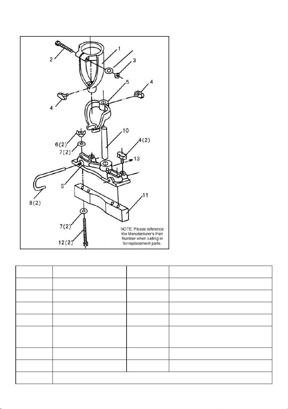
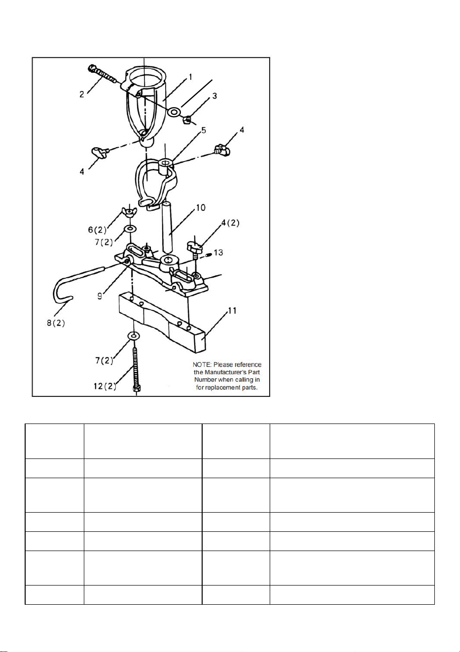
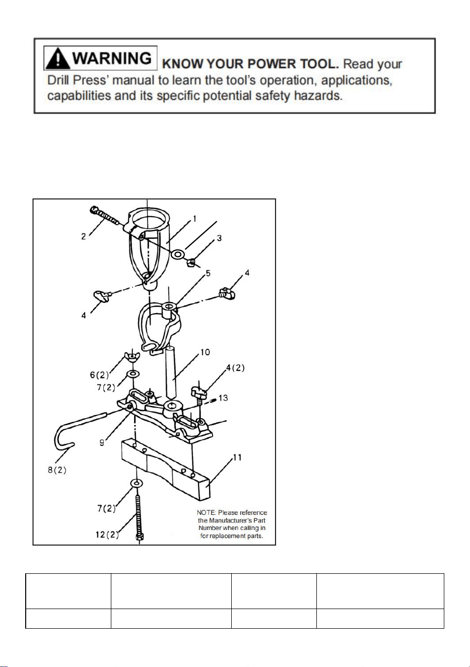
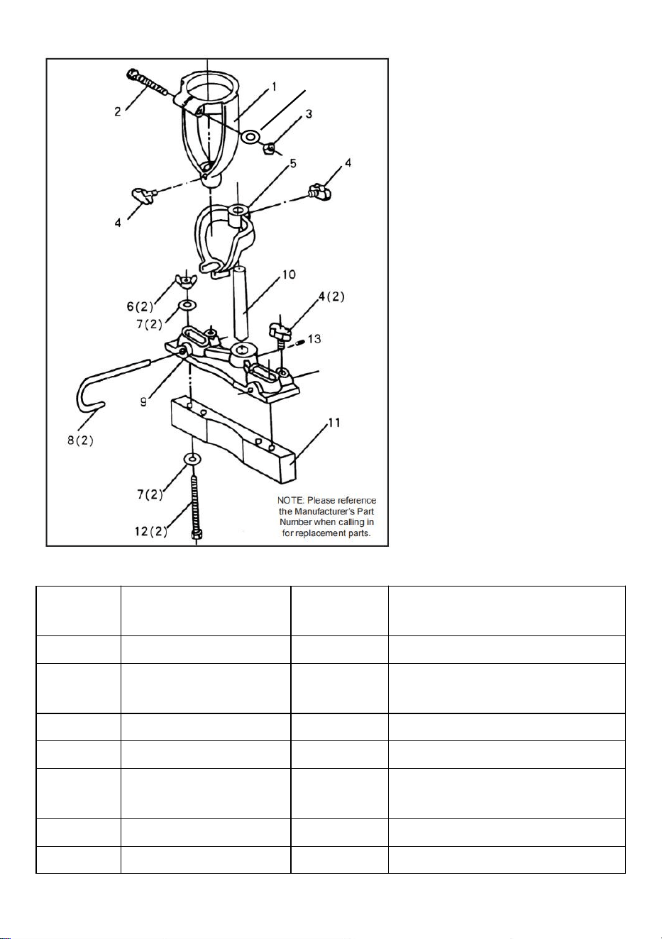
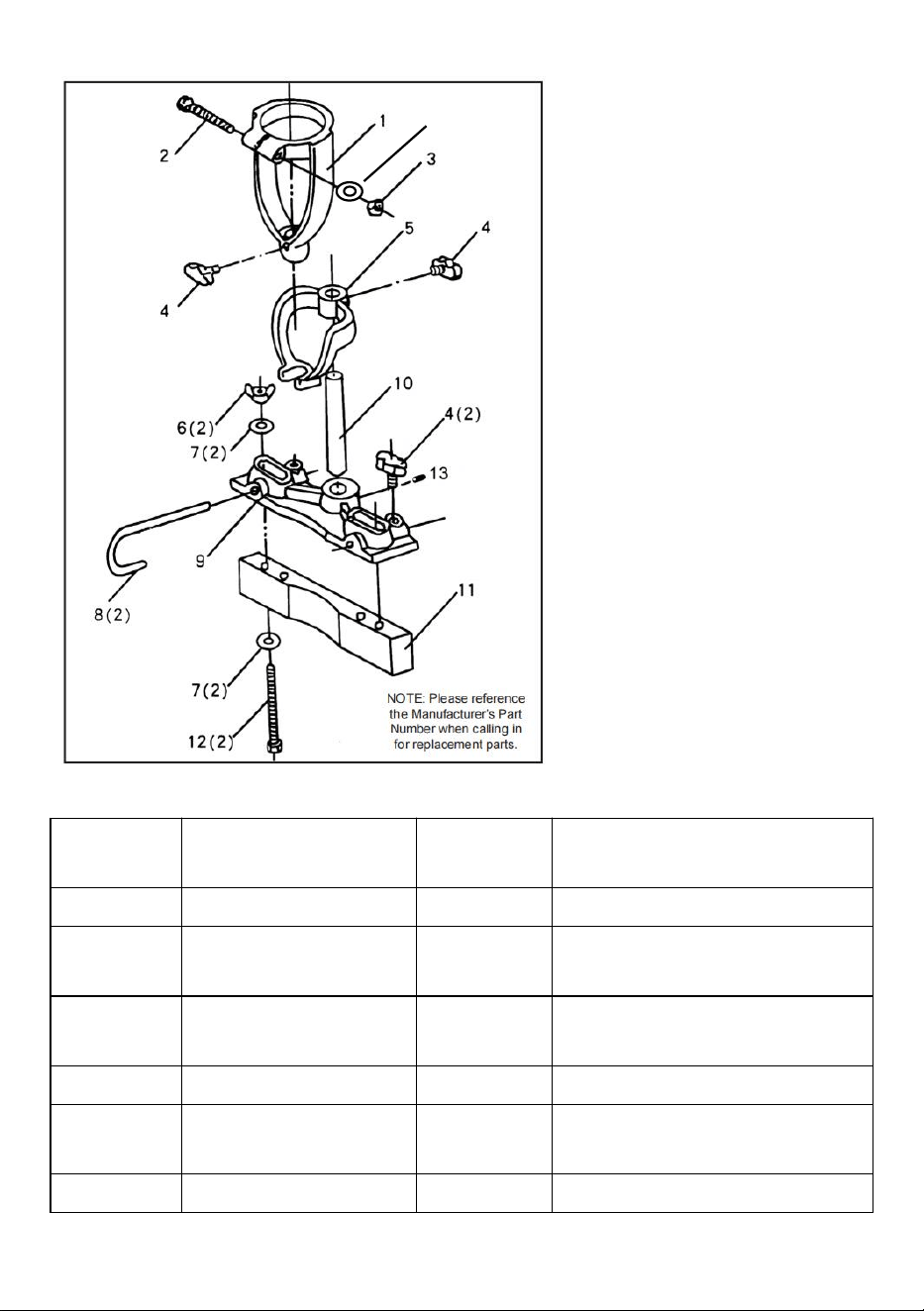
Exploded view of the product part.
14
PARTS LIST.
KEY NO
DESCRIPTION
KEY NO
DESCRIPTION
1
Chisel Holder
2
5/16-18 x 2-1/2” Bolt
3
5/16-18 Hex Nut
4
Wing Nut with Treaded Stud
5
Hold Down Bracket
6
5/16-18 Wing Nut
7
Washer
8
Curved Guide Rods
9
Rod Holding
Casting
10
Hold Down Steel Rod
11
Fence
12
5/16-18 x 4” Bolt
13
Hex Screw
14
Washer
15
Chisels & Drill Bits (1/4, 5/8, 3/8, 1/2) *4 (not shown)
- 9 -
Note: Specifications, photos, drawings, and information in this book
manual represents the current model at the time the manual was written.
Changes and improvements may be made at any time without obligation
Modification of previously delivered units by VEVOR.

- 10 -
Manufacturer: Shanghaimuxinmuyeyouxiangongsi
Address: Shuangchenglu 803nong11hao1602A-1609shi, baoshanqu,
shanghai 200000 CN.
Imported to AUS: SIHAO PTY LTD, 1 ROKEVA STREETEASTWOOD
NSW 2122 Australia
Imported to USA: Sanven Technology Ltd., Suite 250, 9166 Anaheim
Place, Rancho Cucamonga, CA 91730
REP
EC
E-CrossStu GmbH
Mainzer Landstr.69, 60329 Frankfurt am Main.
REP
UK
YH CONSULTING LIMITED.
C/O YH Consulting Limited Office 147, Centurion House,
London Road, Staines-upon-Thames, Surrey, TW18 4AX


- 2 -
Assistance technique et certificat de garantie électronique
www.vevor.com/support
KIT DE FIXATION POUR MORTAISAGE
INSTRUCTIONS
MODÈLE:DPA65
We continue to be committed to provide you tools with competitive price.
"Save Half", "Half Price" or any other similar expressions used by us only represents an
estimate of savings you might benefit from buying certain tools with us compared to the major
top brands and does not necessarily mean to cover all categories of tools offered by us. You
are kindly reminded to verify carefully when you are placing an order with us if you are
actually saving half in comparison with the top major brands.

- 1 -
MODÈLE:DPA65
Have product questions? Need technical support? Please feel free to
contact us:
Technical Support and E-Warranty Certificate
www.vevor.com/support
NEED HELP? CONTACT US!
This is the original instruction, please read all manual instructions
carefully before operating. VEVOR reserves a clear interpretation of our
user manual. The appearance of the product shall be subject to the
product you received. Please forgive us that we won't inform you again if
there are any technology or software updates on our product.
MORTISING ATTACHMENT KIT
- 2 -
Avertissement : Pour réduire le risque de blessure, l'utilisateur
doit lire attentivement le manuel d'instructions.
Cet appareil est conforme à la partie 15 des règles FCC. Son
fonctionnement est soumis aux deux conditions suivantes : (1)
Cet appareil ne doit pas provoquer d'interférences nuisibles et
(2) cet appareil doit accepter toute interférence reçue, y
compris les interférences susceptibles de provoquer un
fonctionnement indésirable.
Ce produit est soumis aux dispositions de la directive
européenne 2012/19/CE. Le symbole représentant une
poubelle barrée indique que le produit nécessite une collecte
sélective des déchets dans l'Union européenne. Ceci
s'applique au produit et à tous les accessoires marqués de ce
symbole. Les produits marqués comme tels ne peuvent pas
être jetés avec les ordures ménagères normales, mais doivent
être déposés dans un point de collecte pour le recyclage des
appareils électriques et électroniques.
INTRODUCTION
L'accessoire de mortaisage convertit votre perceuse à colonne en une
mortaisage précise
machine. Il est idéal pour percer des trous carrés pour les joints à tenon
et à mortaise couramment utilisés dans les meubles, les armoires, les
châssis, les ateliers de modélisme et autres usines de menuiserie.
Le kit de fixation de mortaisage peut être installé sur la plupart des
perceuses à colonne dotées d'un collier.
taille de : 52,5 mm, 55 mm, 60 mm ou 65 mm.
Le nom de l’inventaire du kit.

- 3 -
N. Ensemble porte-burin * 1
O. Maintenez le support enfoncé *1
P. Bagues * 4
Q. Tige de maintien * 1
R. Burins et forets (1/4, 5/8 , 3/8, 1/2) *4
S. Clôture *1
T. Moulage de maintien de tige * 1
U. Tiges de guidage incurvées * 1
V. Clé hexagonale 4mm * 1
W. Grands écrous à oreilles * 4
X. Boulons hexagonaux 5/16-18 x 4 * 2
Rondelles *4 Écrous à oreilles *2
Y. Étui de transport avec *1
Z. Instructions (non illustrées) *1

- 4 -
INSTALLATION INSTRUCTIONS
MONTAGE SUR LA TABLE DE PERCEUSE.
Nous vous recommandons d'installer un panneau de contreplaqué 1/2
sur la table de la perceuse à colonne.
Il peut être maintenu en place en l'insérant sous le guide de mortaisage.
Percer
trous dans le contreplaqué pour correspondre aux fentes de la table. Le
contreplaqué sera
éviter d'endommager le burin à mortaiser et le foret s'il le faut
heurter la table de la perceuse à colonne par accident. C'est aussi un
moyen simple de
augmentez la taille de la table de la perceuse à colonne pour contenir vos
projets.
MONTAGE DU PORTE-CISEAU.
3. Montez le support de burin (A) sur ou juste au-dessus de la base du
fourreau de la perceuse à colonne, avec le boulon de fixation du support
tourné vers l'extérieur, à l'écart de
la colonne de la perceuse à colonne. Pour un bon ajustement, une
bague (C) peut être nécessaire
à insérer dans le collier supérieur du porte-burin.
4. Une fois installé, serrez l'écrou et le boulon sur le support de burin pour
empêcher l'accessoire de glisser.
Installez des ciseaux à mortaise et tenon et des forets.

- 5 -
3. Quatre tailles de burins et d'embouts à mortaiser Hollow Chisel (E) sont
inclus
avec le kit - 1/4”, 5/8 ” , 3/8” et 1/2”. Utilisez uniquement la bonne
combinaison de ciseaux avec la mèche correspondante. Ces outils sont
fourni rectifié en usine et DOIT être affûté avant utilisation. Si soit
l'un est émoussé, il y aura une friction excessive avec une accumulation
de chaleur, ce qui
cela rendra l'opération de perçage difficile et endommagera les outils.
Consulter
des livres sur le travail du bois ou des articles de magazines sur les
techniques appropriées pour
mettre des arêtes vives sur ces objets.
4. Aucune bague n'est requise pour installer les tiges du foret dans le
burin
collier du support, car ils ont tous deux le même diamètre. La tige du
burin sera maintenue par le mandrin à clé de la perceuse à colonne, tout
comme le serait un foret normal.
INSTALLATION DU MÈCHE ET DU CISEL.
5. Insérez le foret à travers le ciseau et dans la clé de la perceuse à
colonne.
mandrin. Serrez le mandrin uniquement à la main.
6. Insérez le burin dans le porte-burin et fixez-le en place avec le
écrou papillon. REMARQUE : Serrez le ciseau de manière à ce que son
épaule soit à environ
1/32" sous le bas du support.
7. Poussez le foret jusqu'en butée dans le mandrin et fixez-le.
placer avec la clé du mandrin. L'extrémité du foret doit être contre
l'extrémité du ciseau carré.
8. Desserrez l'écrou à oreilles fixant le burin et déplacez le burin vers le
haut pour
occupez l'espace de 1/32" précédemment laissé à l'étape 2. Serrez le
ciseau en place. Cette méthode garantit qu'il y a un jeu approprié entre
les lèvres coupantes du foret et les pointes du ciseau.

- 6 -
Lorsqu'il est utilisé, le ciseau carré coupe le bois, forçant le matériau
coupé vers l'intérieur. Le foret découpe ensuite le centre du trou et dirige
le matériau coupé au ciseau vers le haut hors du trou en un seul
mouvement.
Les boulons hexagonaux (K) fournis avec le kit sont suffisamment
longs pour passer
le support de maintien, la clôture, le contreplaqué et la table de la
perceuse à colonne. Insérez le
boulon hexagonal dans les fentes de chacun. Utilisez des rondelles sous
le boulon à tête hexagonale et sous l'écrou à oreilles pour répartir la
pression de maintien.
ASSEMBLEZ LE SUPPORT DE MAINTIEN.
3. Insérez la tige de maintien (D) dans le trou central du support de tige.
Moulage (G) et fixez-le en place avec la vis hexagonale. Une clé
hexagonale de 4 mm (I) est fournie à cet effet.
4. Faites glisser le support de maintien (B) vers le bas sur la tige de
maintien. La prise
Le bas peut être ajusté de haut en bas sur la tige selon les besoins pour
appliquer une légère pression sur votre travail en cours de forage. Ce
support maintiendra votre projet maintenu lorsque le burin à mortaiser et
le foret seront relâchés et retirés du trou qu'ils étaient en train de percer.
INSTALLEZ LA TIGE DE GUIDAGE COURBE.
3. Insérez les deux tiges de guidage incurvées (H) dans les trous
horizontaux qui sont
de chaque côté du moulage de maintien de la tige et fixez-les en position
avec les écrous à oreilles fournis.
4. Les tiges de guidage doivent être positionnées sur la face avant de
votre ouvrage, afin
qu'ils exercent une pression contre le bois et poussent votre projet
contre la clôture.
- 7 -
Schéma de principe de l'assemblage fini
INSTALLATION.
4. Placez votre pièce à travailler sur la table de la perceuse à colonne et
ajustez la hauteur de la table.
de sorte que le burin à mortaiser et la mèche soient à environ 1/2"
au-dessus du travail.
5. Déterminez la profondeur de la mortaise que vous souhaitez couper et
réglez le foret
appuyez sur la butée de profondeur jusqu'à cette distance.
6. Réglez la distance entre la clôture de manière à ce que le burin et la

- 8 -
mèche se trouvent à l'endroit où vous
voulez pour percer la mortaise.
Marquez votre pièce à travailler avec l'emplacement exact de la ou
des mortaises à percer.
Fixez votre travail en place contre le guide avec les tiges de guidage,
ainsi qu'avec le support de maintien.
Déplacez le guide vers l'intérieur ou l'extérieur jusqu'à ce que le
ciseau s'aligne parfaitement avec les lignes de mortaise marquées sur
votre travail.
Fixez le guide en position avec les deux boulons hexagonaux qui
traversent la table de moulage, le guide et la perceuse à colonne.
Opération.
7. Les meilleures vitesses de perceuse à colonne se situent entre 650 et
1 800 tr/min.
8. Utilisez des vitesses inférieures sur les bois durs.
9. Assurez-vous que le ciseau est carré/parallèle à la clôture.
10. Testez la perceuse sur des déchets des mêmes bois de votre projet
pour définir le
positions de mortaisage et vitesse de la perceuse à colonne.
11. Coupez d'abord l'extérieur, les extrémités de la mortaise, puis
effectuez des coupes qui se chevauchent.
entre les deux pour finir la mortaise.
12. Soulevez souvent le ciseau pour éliminer les copeaux et éviter le
colmatage.
- 9 -
Vue éclatée de la pièce du produit.
14
LISTE DES PIECES.
CLE
NON
DESCRIPTION
CLE NON
DESCRIPTION
1
Porte-burin
2
Boulon 5/16-18 x 2-1/2”
3
Écrou hexagonal
5/16-18
4
Écrou à oreilles avec goujon
fileté
5
Maintenir le support
6
Écrou à oreilles 5/16-18
7
Machine à laver
8
Tiges de guidage incurvées
9
Tige Tenir le
casting
dix
Maintenir la tige en acier
11
Clôture
12
Boulon 5/16-18 x 4"

- 10 -
13
Vis hexagonale
14
Machine à laver
15
Burins et forets (1/4, 5/8 , 3/8, 1/2) *4 (non illustrés)
Remarque : Les spécifications, les photos, les dessins et les informations
contenues dans ce manuel représentent le modèle actuel au moment de la
rédaction du manuel.
Des modifications et des améliorations peuvent être apportées à tout
moment sans engagement
Modification des unités précédemment livrées par VEVOR.

- 11 -
Fabricant : Shanghaimuxinmuyeyouxiangongsi
Adresse : Shuangchenglu 803nong11hao1602A-1609shi, baoshanqu,
Shanghai 200000 CN.
Importé en Australie : SIHAO PTY LTD, 1 ROKEVA STREETASTWOOD
NSW 2122 Australie
Importé aux États-Unis : Sanven Technology Ltd., Suite 250, 9166
Anaheim Place, Rancho Cucamonga, CA 91730

- 12 -
REP
EC
E-CrossStu GmbH
Mainzer Landstr.69, 60329 Frankfurt am Main.
REP
UK
YH CONSULTING LIMITED.
C/O YH Consulting Limited Office 147, Centurion House,
London Road, Staines-upon-Thames, Surrey, TW18 4AX


- 2 -
Zertifikat für technischen Support und E-Garantie
www.vevor.com/support
STEMMBEFESTIGUNGSSATZ
ANWEISUNGEN
MODELL: DPA65
We continue to be committed to provide you tools with competitive price.
"Save Half", "Half Price" or any other similar expressions used by us only represents an
estimate of savings you might benefit from buying certain tools with us compared to the major
top brands and does not necessarily mean to cover all categories of tools offered by us. You
are kindly reminded to verify carefully when you are placing an order with us if you are
actually saving half in comparison with the top major brands.

- 1 -
MODELL: DPA65
Have product questions? Need technical support? Please feel free to
contact us:
Technical Support and E-Warranty Certificate
www.vevor.com/support
NEED HELP? CONTACT US!
This is the original instruction, please read all manual instructions
carefully before operating. VEVOR reserves a clear interpretation of our
user manual. The appearance of the product shall be subject to the
product you received. Please forgive us that we won't inform you again if
there are any technology or software updates on our product.
MORTISING ATTACHMENT KIT
- 2 -
Warnung: Um das Verletzungsrisiko zu verringern, muss der
Benutzer die Bedienungsanleitung sorgfältig lesen.
Dieses Gerät entspricht Teil 15 der FCC-Bestimmungen. Der
Betrieb unterliegt den folgenden beiden Bedingungen: (1)
Dieses Gerät darf keine schädlichen Störungen verursachen
und (2) dieses Gerät muss alle empfangenen Störungen
akzeptieren, einschließlich Störungen, die einen
unerwünschten Betrieb verursachen können.
Dieses Produkt unterliegt den Bestimmungen der
europäischen Richtlinie 2012/19/EG. Das Symbol einer
durchgestrichenen Mülltonne weist darauf hin, dass das
Produkt in der Europäischen Union einer getrennten
Müllsammlung bedarf. Dies gilt für das Produkt und alle
Zubehörteile, die mit diesem Symbol gekennzeichnet sind. Als
solche gekennzeichnete Produkte dürfen nicht über den
normalen Hausmüll entsorgt werden, sondern müssen an
einer Sammelstelle für das Recycling von Elektro- und
Elektronikgeräten abgegeben werden
INTRODUCTION
Der Stemmaufsatz verwandelt Ihre Bohrmaschine in eine präzise
Stemmmaschine
Maschine. Es ist ideal zum Bohren von quadratischen Löchern für
Einsteck- und Zapfenverbindungen, die häufig in Möbeln, Schränken,
Flügeln, Musterwerkstätten und anderen Holzbearbeitungsbetrieben
verwendet werden.
Das Stemmbefestigungsset kann an den meisten Bohrmaschinen mit
Spannschelle montiert werden
Größe: 52,5 mm, 55 mm, 60 mm oder 65 mm.
Der Name des Kit-Inventars.
- 3 -
AA. Meißelhalter-Baugruppe *1
AB. Halteklammer *1
AC. Buchsen *4
AD. Halten Unten Stange * 1
AE. Meißel und Bohrer (1/4, 5/ 8 , 3/8, 1/2) *4
AF. Zaun *1
AG. Stange Halten Casting * 1
AH. Gebogene Führungsstangen * 1
AI. Inbusschlüssel 4mm *1
AJ. Große Flügelmuttern *4
AK. 5/16-18 x 4 Sechskantschrauben *2
Unterlegscheiben *4 Flügelmuttern *2

- 4 -
AL. Tragetasche mit *1
AM. Anleitung (nicht abgebildet) *1
INSTALLATION INSTRUCTIONS
MONTAGE AUF DEM BOHRMASCHINENTISCH.
Wir empfehlen, auf dem Bohrmaschinentisch eine 1/2-Sperrholzplatte zu
installieren.
Es kann an Ort und Stelle gehalten werden, indem es unter den
Stemmzaun geschoben wird. Bohrer
Löcher im Sperrholz, die zu den Schlitzen im Tisch passen. Das Sperrholz
wird
Vermeiden Sie gegebenenfalls Schäden an Stemmmeißel und Bohrer
Sie könnten versehentlich gegen den Metalltisch der Bohrmaschine
stoßen. Es ist auch eine einfache Möglichkeit
Erhöhen Sie die Größe des Bohrmaschinentisches, um Ihre Projekte
aufzunehmen.
MONTAGE DES MEISSELHALTERS.
5. Montieren Sie den Meißelhalter (A) auf oder direkt über der Basis der
Bohrmaschinenpinole, wobei die Befestigungsschraube des Halters
nach außen und von dieser weg zeigt
die Bohrständersäule. Für einen ordnungsgemäßen Sitz ist
möglicherweise eine Buchse (C) erforderlich
Wird in den oberen Kragen des Meißelhalters eingesetzt.
6. Ziehen Sie nach der Installation die Mutter und die Schraube am
Meißelhalter fest, um ein Verrutschen des Aufsatzes zu verhindern.

- 5 -
Installieren Sie Zapfenmeißel und Bohrer.
5. Im Lieferumfang sind Hohlmeißel-Stemmmeißel und Bits (E) in vier
Größen enthalten
mit dem Kit - 1/4“, 5/8 “ , 3/8“ und 1/2“. Verwenden Sie nur die richtige
Kombination der Meißel mit dem entsprechenden Bohrer. Diese
Werkzeuge sind
werden werkseitig geschliffen geliefert und MÜSSEN vor der
Verwendung geschärft werden. Wenn entweder
Wenn eines stumpf ist, kommt es zu übermäßiger Reibung und
Hitzestau
erschwert den Bohrvorgang und beschädigt die Werkzeuge.
Konsultieren
Holzbearbeitungsbücher oder Zeitschriftenartikel über die richtigen
Techniken dazu
scharfe Kanten an diesen Gegenständen anbringen.
6. Für den Einbau der Bohrerschäfte in den Meißel sind keine Buchsen
erforderlich
am Kragen des Halters, da beide den gleichen Durchmesser haben. Der
Schaft des Meißels wird vom Zahnkranzbohrfutter der Bohrmaschine
gehalten, genau wie ein normaler Bohrer.
INSTALLIEREN VON BIT UND MEISSEL.
9. Führen Sie den Bohrer durch den Meißel und in den Keil der
Bohrmaschine ein
Futter. Ziehen Sie das Spannfutter nur handfest an.
10. Setzen Sie den Meißel in den Meißelhalter ein und sichern Sie ihn mit
dem
Flügelmutter. HINWEIS: Spannen Sie den Meißel so ein, dass seine
Schulter ca
1/32 Zoll unter der Unterseite des Halters.
11. Schieben Sie den Bohrer bis zum Anschlag in das Bohrfutter und
befestigen Sie ihn
mit dem Bohrfutterschlüssel platzieren. Das Ende des Bohrers sollte am

- 6 -
Ende des Vierkantmeißels anliegen.
12. Lösen Sie die Flügelmutter, mit der der Meißel befestigt ist, und
bewegen Sie den Meißel nach oben
Nehmen Sie den zuvor in Schritt 2 verbleibenden 1/32-Zoll-Platz ein.
Ziehen Sie den Meißel fest. Diese Methode stellt sicher, dass zwischen
den Schneidlippen des Bohrers und den Spitzen des Meißels ein
ausreichender Abstand besteht.
Bei der Verwendung schneidet der Vierkantmeißel in das Holz und
drückt das Schnittgut nach innen. Der Bohrer schneidet dann die Mitte
des Lochs heraus und leitet das meißelgeschnittene Material in einer
einzigen Bewegung nach oben aus dem Loch.
Die im Kit enthaltenen Sechskantschrauben (K) sind lang genug, um
durchgesteckt zu werden
die Niederhalteklammer, den Anschlag, das Sperrholz und den Tisch der
Bohrmaschine. Fügen Sie die ein
Führen Sie die Sechskantschraube jeweils durch die Schlitze.
Verwenden Sie Unterlegscheiben unter der Sechskantschraube und
unter der Flügelmutter, um den Haltedruck zu verteilen.
MONTIEREN SIE DIE HALTEHALTERUNG.
5. Führen Sie die Niederhaltestange (D) in das mittlere Loch der
Stangenhalterung ein
Gussteil (G) und befestigen Sie es mit der Sechskantschraube. Hierzu
wird ein 4-mm-Inbusschlüssel (I) mitgeliefert.
6. Schieben Sie die Niederhaltehalterung (B) nach unten auf die
Niederhaltestange. Der Halt
Sie können die Bohrstange je nach Bedarf nach oben und unten
verstellen, um einen leichten Druck nach unten auf Ihr zu bohrendes
Werkstück auszuüben. Diese Halterung hält Ihr Projekt fest, wenn
Stemmmeißel und Bohrer gelöst und aus dem Loch gezogen werden,
das sie gebohrt haben.
INSTALLIEREN SIE DIE GEBOGENE FÜHRUNGSSTANGE.
5. Führen Sie die beiden gebogenen Führungsstangen (H) in die
- 7 -
horizontalen Löcher ein
auf beiden Seiten der Stange, die den Guss hält, und sichern Sie sie mit
den mitgelieferten Flügelmuttern.
6. Die Führungsstangen sollten also an der Vorderseite Ihres Werkstücks
positioniert werden
dass sie Druck auf das Holz ausüben und Ihr Projekt gegen den Zaun
drücken.
Schematische Darstellung der fertigen Baugruppe
AUFSTELLEN.
7. Legen Sie Ihr Werkstück auf den Bohrmaschinentisch und stellen Sie

- 8 -
die Tischhöhe ein
so dass sich Stemmmeißel und Bohrer etwa 1/2 Zoll über dem
Werkstück befinden.
8. Bestimmen Sie die Tiefe des Zapfenlochs, das Sie schneiden möchten,
und stellen Sie den Bohrer ein
Tiefenanschlag auf diesen Abstand drücken.
9. Stellen Sie den Zaunabstand so ein, dass sich Meißel und Bohrer an
der von Ihnen gewünschten Stelle befinden
Ich brauche zum Bohren des Einsteckschlosses.
Markieren Sie Ihr Werkstück mit der genauen Position der
Aussparungen, die gebohrt werden müssen.
Sichern Sie Ihr Werkstück mit den Führungsstangen und dem
Niederhalter am Zaun.
Bewegen Sie den Zaun hinein oder heraus, bis der Meißel perfekt mit
den auf Ihrem Werk markierten Zapfenlinien übereinstimmt.
Befestigen Sie den Anschlag mit den beiden Sechskantschrauben, die
durch das Gussstück, den Anschlag und den Tisch der Bohrmaschine
verlaufen.
Betrieb.
13. Die besten Drehzahlen für Bohrmaschinen liegen zwischen 650 und
1800 U/min.
14. Verwenden Sie bei Harthölzern niedrigere Geschwindigkeiten.
15. Stellen Sie sicher, dass der Meißel rechtwinklig/parallel zum Zaun ist.
16. Testen Sie den Bohrer mit Restholz aus den gleichen Hölzern wie bei
Ihrem Projekt, um die Einstellung vorzunehmen
Stemmpositionen und Bohrmaschinengeschwindigkeit.
17. Schneiden Sie zuerst die äußeren Enden des Einstecklochs ab und
machen Sie dann überlappende Schnitte
zwischen den beiden, um das Einsteckschloss fertigzustellen.
18. Heben Sie den Meißel häufig an, um Späne zu entfernen und ein
Verstopfen zu verhindern.
- 9 -
Explosionszeichnung des Produktteils.
14
LISTE DER EINZELTEILE.
SCHLÜSSEL
NR
BESCHREIBUNG
SCHLÜSSEL
NR
BESCHREIBUNG
1
Meißelhalter
2
5/16-18 x 2-1/2 Zoll
- 10 -
Bolzen
3
5/16-18
Sechskantmutter
4
Flügelmutter mit
Gewindebolzen
5
Halten Sie die
Klammer gedrückt
6
5/16-18 Flügelmutter
7
Waschmaschine
8
Gebogene
Führungsstangen
9
Stange Holding
Casting
10
Halten Sie die
Stahlstange
gedrückt
11
Zaun
12
5/16-18 x 4 Zoll
Bolzen
13
Sechskantschraube
14
Waschmaschine
15
Meißel und Bohrer (1/4, 5/8 , 3/8, 1/2) *4 (nicht abgebildet)
Hinweis: Die Spezifikationen, Fotos, Zeichnungen und Informationen in
diesem Handbuch stellen das aktuelle Modell zum Zeitpunkt der Erstellung
des Handbuchs dar.
Änderungen und Verbesserungen sind jederzeit unverbindlich möglich
Änderung bereits gelieferter Einheiten durch VEVOR.

- 11 -
Hersteller: Shanghaimuxinmuyeyouxiangongsi
Adresse : Shuangchenglu 803nong11hao1602A-1609shi, Baoshanqu,
Shanghai 200000 CN.
Importiert nach AUS: SIHAO PTY LTD, 1 ROKEVA STREETEASTWOOD
NSW 2122 Australien
In die USA importiert: Sanven Technology Ltd., Suite 250, 9166 Anaheim
Place, Rancho Cucamonga, CA 91730

- 12 -
REP
EC
E-CrossStu GmbH
Mainzer Landstr.69, 60329 Frankfurt am Main.
REP
UK
YH CONSULTING LIMITED.
C/O YH Consulting Limited Office 147, Centurion House,
London Road, Staines-upon-Thames, Surrey, TW18 4AX


- 2 -
Supporto tecnico e certificato di garanzia elettronica
www.vevor.com/support
KIT DI FISSAGGIO PER MORTASATRICE
ISTRUZIONI
MODELLO: DPA65
We continue to be committed to provide you tools with competitive price.
"Save Half", "Half Price" or any other similar expressions used by us only represents an
estimate of savings you might benefit from buying certain tools with us compared to the major
top brands and does not necessarily mean to cover all categories of tools offered by us. You
are kindly reminded to verify carefully when you are placing an order with us if you are
actually saving half in comparison with the top major brands.

- 1 -
MODELLO:DPA65
Have product questions? Need technical support? Please feel free to
contact us:
Technical Support and E-Warranty Certificate
www.vevor.com/support
NEED HELP? CONTACT US!
This is the original instruction, please read all manual instructions
carefully before operating. VEVOR reserves a clear interpretation of our
user manual. The appearance of the product shall be subject to the
product you received. Please forgive us that we won't inform you again if
there are any technology or software updates on our product.
MORTISING ATTACHMENT KIT
- 2 -
Avvertenza: per ridurre il rischio di lesioni, l'utente deve
leggere attentamente il manuale di istruzioni.
Questo dispositivo è conforme alla Parte 15 delle norme FCC.
Il funzionamento è soggetto alle seguenti due condizioni: (1)
Questo dispositivo non può causare interferenze dannose e
(2) questo dispositivo deve accettare qualsiasi interferenza
ricevuta, comprese le interferenze che potrebbero causare un
funzionamento indesiderato.
Questo prodotto è soggetto alle disposizioni della Direttiva
Europea 2012/19/CE. Il simbolo del bidone della spazzatura
barrato indica che nell'Unione Europea il prodotto richiede la
raccolta differenziata dei rifiuti. Ciò vale per il prodotto e tutti gli
accessori contrassegnati da questo simbolo. I prodotti
contrassegnati come tali non possono essere smaltiti con i
normali rifiuti domestici, ma devono essere portati in un punto
di raccolta per il riciclaggio di dispositivi elettrici ed elettronici
INTRODUCTION
L'accessorio per mortasatura converte il tuo trapano a colonna in una
mortasatrice accurata
macchina. È ideale per eseguire fori quadrati per giunti a mortasa e
tenone comunemente utilizzati in mobili, armadi, ante, modellisti e altri
impianti di lavorazione del legno.
Il kit di attacco per mortasatura può essere installato sulla maggior parte
dei trapani a colonna dotati di collare
dimensione di: 52,5 mm, 55 mm, 60 mm o 65 mm.
Il nome dell'inventario del kit.
- 3 -
AN. Gruppo porta scalpello *1
AO. Tieni premuta la staffa *1
AP. Boccole *4
AQ. Tenere premuto l'asta *1
AR. Scalpelli e punte da trapano (1/4, 5/8 , 3/8, 1/2) *4
AS. Recinzione *1
AT. Casting con supporto per asta *1
AU. Aste guida curve *1
AV. Chiave esagonale da 4 mm *1
AW. Dadi ad alette grandi *4
AX. Bulloni esagonali 5/16-18 x 4 *2
Rondelle *4 Dadi ad alette *2
AY. Custodia da trasporto con *1
AZ. Istruzioni (non mostrate) *1

- 4 -
INSTALLATION INSTRUCTIONS
MONTAGGIO SULLA TAVOLA DEL TRAPANO.
Si consiglia di installare un pannello di compensato da 1/2 sul tavolo del
trapano.
Può essere tenuto in posizione inserendolo sotto la guida di mortasatura.
Trapano
fori nel compensato per abbinare le fessure nel tavolo. Il compensato lo
farà
evitare danni allo scalpello per mortasatura e alla punta del trapano, se
necessario
colpire accidentalmente il tavolo del trapano metallico. È anche un modo
semplice per farlo
aumenta le dimensioni del tavolo del trapano per contenere i tuoi progetti.
MONTAGGIO DEL PORTASCALPELLO.
7. Montare il supporto per scalpello (A) sopra o appena sopra la base della
penna del trapano a colonna, con il bullone di fissaggio del supporto
rivolto verso l'esterno, lontano da
la colonna del trapano. Per un corretto adattamento, potrebbe essere
necessaria una boccola (C).
da inserire all'interno del collare superiore del porta scalpello.
8. Una volta installato, serrare il dado e il bullone sul supporto dello
scalpello per evitare che l'accessorio scivoli.
Installa scalpelli per mortasa e tenone e punte da trapano.
7. Sono incluse quattro dimensioni di scalpelli e punte per mortasatura a

- 5 -
scalpello cavo (E).
con il kit - 1/4”, 5/ 8 ”, 3/8” e 1/2”. Utilizzare solo la combinazione corretta
degli scalpelli con la punta corrispondente. Questi strumenti sono
fornito macinato in fabbrica e DEVE essere affilato prima dell'uso. Se
l'uno o l'altro
uno è opaco, ci sarà un attrito eccessivo con accumulo di calore, che
renderà difficoltosa l'operazione di foratura e danneggerà gli utensili.
Consultare
libri sulla lavorazione del legno o articoli di riviste sulle tecniche
adeguate
mettere bordi taglienti su questi oggetti.
8. Non sono necessarie boccole per installare i gambi della punta nello
scalpello
collare del supporto, poiché entrambi hanno lo stesso diametro. Il gambo
dello scalpello verrà trattenuto dal mandrino con chiavetta del trapano,
proprio come verrebbe trattenuta una normale punta da trapano.
INSTALLAZIONE DELLA PUNTA E DELLO SCALPELLO.
13. Inserire la punta del trapano attraverso lo scalpello e nella chiave del
trapano
mandrino. Stringere solo a mano il mandrino.
14. Inserire lo scalpello nel porta scalpello e fissarlo in posizione con
dado ad alette. NOTA: Bloccare lo scalpello in modo tale che la sua
spalla si trovi all'incirca
1/32" sotto il fondo del supporto.
15. Spingere la punta del trapano fino in fondo nel mandrino e fissarla
posizionare con la chiave del mandrino. L'estremità della punta del
trapano dovrebbe essere contro l'estremità dello scalpello quadrato.
16. Allentare il dado ad alette che fissa lo scalpello e spostare lo scalpello
verso l'alto
occupare lo spazio di 1/32” precedentemente lasciato al passaggio 2.
Stringere lo scalpello in posizione. Questo metodo garantisce che vi sia
uno spazio adeguato tra i labbri taglienti della punta del trapano e le
punte dello scalpello.

- 6 -
Quando è in uso, lo scalpello quadrato taglierà il legno, forzando il
materiale tagliato verso l'interno. La punta del trapano ritaglia quindi il
centro del foro e dirige il materiale tagliato con lo scalpello fuori dal foro
con un unico movimento.
I bulloni esagonali (K) forniti con il kit sono sufficientemente lunghi da
poter essere inseriti
la staffa di fissaggio, la recinzione, il compensato e il tavolo del trapano.
Inserisci il
bullone esagonale attraverso le fessure di ciascuno. Utilizzare le
rondelle sotto il bullone a testa esagonale e sotto il dado ad alette per
distribuire la pressione di tenuta.
MONTARE LA STAFFA DI TENUTA.
7. Inserire l'asta di sostegno (D) nel foro centrale del sostegno dell'asta
Fusione (G) e fissarlo in posizione con la vite esagonale. A questo scopo
viene fornita una chiave esagonale da 4 mm (I).
8. Far scorrere la staffa di fissaggio (B) verso il basso sull'asta di fissaggio.
La presa
down può essere regolato su e giù sull'asta secondo necessità per
applicare una leggera pressione sul lavoro che viene perforato. Questa
staffa manterrà fermo il tuo progetto quando lo scalpello e la punta per
mortasatura verranno rilasciati ed estratti dal foro che stavano
praticando.
INSTALLARE L'ASTA GUIDA CURVA.
7. Inserire le due aste guida curve (H) nei fori orizzontali presenti
su entrambi i lati dell'asta che sostiene la fusione e fissarli in posizione
con i dadi ad alette in dotazione.
8. Le aste guida dovrebbero essere posizionate sulla parte anteriore del
tuo lavoro, quindi
che facciano pressione sul legno e spingano il tuo progetto contro la
recinzione.

- 7 -
Rappresentazione schematica dell'assieme finito
IMPOSTARE.
10. Posiziona il pezzo da lavorare sul tavolo del trapano e regola l'altezza
del tavolo
in modo che lo scalpello e la punta da mortasatura siano circa 1/2 pollice
sopra il lavoro.
11. Determina la profondità della mortasa che vuoi tagliare e imposta il
trapano
premere il fermo di profondità a questa distanza.
12. Imposta la distanza della recinzione in modo che lo scalpello e la

- 8 -
punta si trovino nella posizione desiderata
vuoi per forare la mortasa.
Contrassegna sul pezzo da lavorare la posizione esatta delle mortase
che devono essere forate.
Fissa il tuo lavoro in posizione contro la recinzione con le aste guida e
anche con la staffa di fissaggio.
Sposta la recinzione dentro o fuori finché lo scalpello non si allinea
perfettamente con le linee di mortasa segnate sul tuo lavoro.
Fissare la recinzione in posizione con i due bulloni esagonali che
attraversano la tavola di fusione, recinzione e trapano a colonna.
Operazione.
19. Le migliori velocità del trapano a colonna sono comprese tra 650 e
1800 giri al minuto.
20. Utilizzare velocità inferiori sui legni duri.
21. Assicurati che lo scalpello sia quadrato/parallelo alla recinzione.
22. Prova il trapano su pezzi di scarto dello stesso legno del tuo progetto
per impostare il
posizioni di mortasatura e velocità del trapano.
23. Tagliare prima le estremità esterne della mortasa, quindi eseguire dei
tagli sovrapposti
tra i due per finire la mortasa.
24. Sollevare spesso lo scalpello per eliminare i trucioli ed evitare
intasamenti.
Vista esplosa della parte del prodotto.

- 9 -
14
ELENCO DELLE PARTI.
CHIAVE
N
DESCRIZIONE
CHIAVE N
DESCRIZIONE
1
Porta scalpello
2
Bullone da 5/16-18 x 2-1/2”.
3
Dado esagonale
5/16-18
4
Dado ad alette con perno
filettato
5
Tenere premuta la
staffa
6
Dado ad alette 5/16-18
7
Rondella
8
Aste guida curve
9
Asta Tenendo il
casting
10
Tenere premuta la barra
d'acciaio
11
Recinzione
12
Bullone 5/16-18 x 4”.

- 10 -
13
Vite esagonale
14
Rondella
15
Scalpelli e punte da trapano (1/4, 5/8 , 3/8, 1/2) *4 (non
mostrato)
Nota: le specifiche, le foto, i disegni e le informazioni contenute in questo
manuale rappresentano il modello attuale al momento della stesura del
manuale.
Modifiche e miglioramenti possono essere apportati in qualsiasi momento
senza impegno
Modifica di unità precedentemente consegnate da VEVOR.

- 11 -
Produttore: Shanghaimuxinmuyeyouxiangongsi
Indirizzo : Shuangchenglu 803nong11hao1602A-1609shi, baoshanqu,
shanghai 200000 CN.
Importato in AUS: SIHAO PTY LTD, 1 ROKEVA STREETEASTWOOD
NSW 2122 Australia
Importato negli Stati Uniti: Sanven Technology Ltd., Suite 250, 9166
Anaheim Place, Rancho Cucamonga, CA 91730

- 12 -
REP
EC
E-CrossStu GmbH
Mainzer Landstr.69, 60329 Frankfurt am Main.
REP
UK
YH CONSULTING LIMITED.
C/O YH Consulting Limited Office 147, Centurion House,
London Road, Staines-upon-Thames, Surrey, TW18 4AX


- 2 -
Soporte técnico y certificado de garantía electrónica
www.vevor.com/support
KIT DE ACCESORIOS PARA MORTAJAR
INSTRUCCIONES
MODELO:DPA65
We continue to be committed to provide you tools with competitive price.
"Save Half", "Half Price" or any other similar expressions used by us only represents an
estimate of savings you might benefit from buying certain tools with us compared to the major
top brands and does not necessarily mean to cover all categories of tools offered by us. You
are kindly reminded to verify carefully when you are placing an order with us if you are
actually saving half in comparison with the top major brands.

- 1 -
MODELO:DPA65
Have product questions? Need technical support? Please feel free to
contact us:
Technical Support and E-Warranty Certificate
www.vevor.com/support
NEED HELP? CONTACT US!
This is the original instruction, please read all manual instructions
carefully before operating. VEVOR reserves a clear interpretation of our
user manual. The appearance of the product shall be subject to the
product you received. Please forgive us that we won't inform you again if
there are any technology or software updates on our product.
MORTISING ATTACHMENT KIT

- 2 -
Advertencia: para reducir el riesgo de lesiones, el usuario
debe leer atentamente el manual de instrucciones.
Este dispositivo cumple con la Parte 15 de las normas de la
FCC. El funcionamiento está sujeto a las dos condiciones
siguientes: (1) Este dispositivo no puede causar interferencias
dañinas y (2) este dispositivo debe aceptar cualquier
interferencia recibida, incluidas las interferencias que puedan
causar un funcionamiento no deseado.
Este producto está sujeto a las disposiciones de la Directiva
Europea 2012/19/CE. El símbolo que muestra un contenedor
con ruedas tachado indica que el producto requiere recogida
selectiva de basura en la Unión Europea. Esto se aplica al
producto y a todos los accesorios marcados con este símbolo.
Los productos marcados como tales no podrán desecharse
con la basura doméstica normal, sino que deberán llevarse a
un punto de recogida para el reciclaje de aparatos eléctricos y
electrónicos.
INTRODUCTION
El accesorio para mortajar convierte su taladradora en una máquina para
mortajar precisa.
máquina. Es ideal para perforar agujeros cuadrados para juntas de
mortaja y espiga que se utilizan comúnmente en muebles, gabinetes,
marcos, talleres de patrones y otras plantas de carpintería.
El kit de accesorios para mortajar se puede instalar en casi cualquier
taladradora con collar.
tamaño de: 52,5 mm, 55 mm, 60 mm o 65 mm.
El nombre del inventario del kit.
- 3 -
BA. Conjunto de soporte de cincel *1
BB. Mantenga presionado el soporte *1
BC. Bujes *4
BD. Varilla de sujeción *1
BE. Cinceles y brocas (1/4, 5/8 , 3/8, 1/2) *4
BF. Valla *1
BG. Fundición de sujeción de varilla * 1
BH. Varillas de guía curvas * 1
BI. Llave hexagonal de 4 mm * 1
BJ. Tuercas de mariposa grandes *4
BK. 5/16-18 x 4 pernos hexagonales *2
Arandelas *4 Tuercas de mariposa *2
BL. Estuche de transporte con *1
BM. Instrucciones (no mostradas) *1

- 4 -
INSTALLATION INSTRUCTIONS
MONTAJE SOBRE LA MESA TALADRO PRENSA.
Recomendamos instalar un panel de madera contrachapada de 1/2 en la
mesa del taladro.
Se puede mantener en su lugar insertándolo debajo de la guía de embutir.
Perforar
agujeros en la madera contrachapada para que coincidan con las ranuras
de la mesa. La madera contrachapada
evitar daños al cincel para mortajar y a la broca si fuera necesario.
golpee la mesa del taladro de metal por accidente. También es una forma
sencilla de
aumente el tamaño de la mesa del taladro para sostener sus proyectos.
MONTAJE DEL PORTA CINCEL.
9. Monte el soporte del cincel (A) sobre o justo encima de la base de la
caña del taladro, con el perno de sujeción del soporte mirando hacia
afuera, lejos de
la columna del taladro. Para un ajuste adecuado, es posible que se
requiera un casquillo (C)
para insertarse dentro del collar superior del soporte del cincel.
10. Una vez instalado, apriete la tuerca y el perno del soporte del cincel
para evitar que el accesorio se resbale.
Instale cinceles de mortaja y espiga y brocas.
9. Se incluyen cuatro tamaños de cinceles y brocas para embutir (E) de

- 5 -
cincel hueco
con el kit - 1/4”, 5/ 8 ”, 3/8” y 1/2”. Utilice sólo la combinación correcta de
los cinceles con su broca correspondiente. Estas herramientas son
suministrado con tierra de fábrica y DEBE afilarse antes de su uso. Si
alguno
Si uno está desafilado, habrá una fricción excesiva con acumulación de
calor, lo que
dificultará la operación de perforación y dañará las herramientas.
Consultar
libros de carpintería o artículos de revistas sobre las técnicas adecuadas
para
poner bordes afilados en estos artículos.
10. No se requieren casquillos para instalar los vástagos de la broca en el
cincel.
collar del soporte, ya que ambos tienen el mismo diámetro. El vástago
del cincel se sujetará con el portabrocas con llave del taladro, tal como
se sujetaría una broca normal.
INSTALACIÓN DE LA BROCA Y EL CINCEL.
17. Inserte la broca a través del cincel y en la llave del taladro.
arrojar. Apriete el portabrocas únicamente a mano.
18. Inserte el cincel en el soporte del cincel y asegúrelo en su lugar con el
tuerca de mariposa. NOTA: Sujete el cincel de modo que su hombro
quede aproximadamente
1/32” por debajo de la parte inferior del soporte.
19. Introduzca la broca en el portabrocas hasta el tope y fíjela
colóquelo con la llave del portabrocas. El extremo de la broca debe estar
contra el extremo del cincel cuadrado.
20. Afloje la tuerca de mariposa que sujeta el cincel y mueva el cincel
hacia arriba para
Ocupe el espacio de 1/32” que quedó anteriormente en el Paso 2.
Apriete el cincel en su lugar. Este método asegura que haya un espacio
adecuado entre los labios cortantes de la broca y las puntas del cincel.
Cuando esté en uso, el cincel cuadrado cortará la madera, forzando el

- 6 -
material cortado hacia adentro. Luego, la broca corta el centro del
agujero y dirige el material cortado con cincel hacia arriba fuera del
agujero con un solo movimiento.
Los pernos hexagonales (K) suministrados con el kit son lo
suficientemente largos para pasar
el soporte de sujeción, la guía, la madera contrachapada y la mesa del
taladro. Insertar el
perno hexagonal a través de las ranuras de cada uno. Utilice arandelas
debajo del perno de cabeza hexagonal y debajo de la tuerca de
mariposa para distribuir la presión de sujeción.
ENSAMBLE EL SOPORTE DE SUJECIÓN.
9. Inserte la varilla de sujeción (D) en el orificio central de la varilla de
sujeción.
Fundición (G) y asegúrelo en su lugar con el tornillo hexagonal. Para ello
se suministra una llave hexagonal de 4 mm (I).
10. Deslice el soporte de sujeción (B) hacia abajo sobre la varilla de
sujeción. La bodega
hacia abajo se puede ajustar hacia arriba y hacia abajo en la varilla
según sea necesario para aplicar una ligera presión hacia abajo sobre el
trabajo que se está perforando. Este soporte mantendrá su proyecto
sujeto cuando el cincel y la broca se suelten y se saquen del orificio que
estaban perforando.
INSTALE LA VARILLA GUÍA CURVA.
9. Inserte las dos varillas guía curvas (H) en los orificios horizontales que
están
a cada lado de la varilla que sostiene la pieza fundida y asegúrelos en
su posición con las tuercas de mariposa suministradas.
10. Las varillas guía deben colocarse en la cara frontal de su trabajo, de
modo que
que hagan presión contra la madera y empujen tu proyecto contra la
valla.

- 7 -
Diagrama esquemático del conjunto terminado.
CONFIGURACIÓN.
13. Coloque su pieza de trabajo en la mesa del taladro y ajuste la altura
de la mesa.
de modo que el cincel y la broca queden aproximadamente 1/2” por
encima del trabajo.
14. Determine la profundidad de la mortaja que desea cortar y configure el
taladro.
presione el tope de profundidad hasta esta distancia.
15. Establezca la distancia de la cerca de modo que el cincel y la broca

- 8 -
estén en el lugar que usted
Quiero perforar la mortaja.
Marque su pieza de trabajo con la ubicación exacta de las mortajas
que deben perforarse.
Asegure su trabajo en su lugar contra la guía con las varillas guía y
también con el soporte de sujeción.
Mueva la guía hacia adentro o hacia afuera hasta que el cincel se
alinee perfectamente con las líneas de mortaja marcadas en su trabajo.
Asegure la guía en su posición con los dos pernos hexagonales que
atraviesan la mesa de fundición, la guía y la taladradora.
Operación.
25. Las mejores velocidades de taladradora están entre 650 y 1800 RPM.
26. Utilice velocidades más bajas en maderas duras.
27. Asegúrese de que el cincel esté cuadrado/paralelo a la guía.
28. Pruebe el taladro en restos de las mismas maderas de su proyecto
para establecer el
posiciones de mortajado y velocidad del taladro.
29. Primero corte los extremos exteriores de la mortaja y luego haga
cortes superpuestos.
entre los dos para terminar la mortaja.
30. Levante el cincel con frecuencia para eliminar las virutas y evitar
obstrucciones.
Vista ampliada de la pieza del producto.
- 9 -
14
LISTA DE PARTES.
LLAVE
NO
DESCRIPCIÓN
LLAVE
NO
DESCRIPCIÓN
1
Titular del cincel
2
Perno de 5/16-18 x 2-1/2”
3
Tuerca hexagonal
5/16-18
4
Tuerca de mariposa con
perno roscado
5
Soporte de sujeción
6
Tuerca de mariposa 5/16-18
7
Lavadora
8
Varillas guía curvas
9
Vara sosteniendo
fundición
10
Mantenga presionada la
varilla de acero
11
Cerca
12
Perno de 5/16-18 x 4”
13
Tornillo hexagonal
14
Lavadora

- 10 -
15
Cinceles y brocas (1/4, 5/8 , 3/8, 1/2) *4 (no se muestran)
Nota: Las especificaciones, fotografías, dibujos e información de este
manual representan el modelo actual en el momento en que se escribió el
manual.
Se podrán realizar cambios y mejoras en cualquier momento sin
compromiso.
Modificación de unidades entregadas anteriormente por VEVOR.

- 11 -
Fabricante: Shanghaimuxinmuyeyouxiangongsi
Dirección : Shuangchenglu 803nong11hao1602A-1609shi, baoshanqu,
shanghai 200000 CN.
Importado a AUS: SIHAO PTY LTD, 1 ROKEVA STREETEASTWOOD
NSW 2122 Australia
Importado a EE. UU.: Sanven Technology Ltd., Suite 250, 9166 Anaheim
Place, Rancho Cucamonga, CA 91730

- 12 -
REP
EC
E-CrossStu GmbH
Mainzer Landstr.69, 60329 Frankfurt am Main.
REP
UK
YH CONSULTING LIMITED.
C/O YH Consulting Limited Office 147, Centurion House,
London Road, Staines-upon-Thames, Surrey, TW18 4AX


- 2 -
Wsparcie techniczne i certyfikat e-gwarancji
www.vevor.com/support
ZESTAW DO MOCOWANIA DO DŁUTOWANIA
INSTRUKCJE
MODEL: DPA65
We continue to be committed to provide you tools with competitive price.
"Save Half", "Half Price" or any other similar expressions used by us only represents an
estimate of savings you might benefit from buying certain tools with us compared to the major
top brands and does not necessarily mean to cover all categories of tools offered by us. You
are kindly reminded to verify carefully when you are placing an order with us if you are
actually saving half in comparison with the top major brands.
- 1 -
MODEL:DPA65
Have product questions? Need technical support? Please feel free to
contact us:
Technical Support and E-Warranty Certificate
www.vevor.com/support
NEED HELP? CONTACT US!
This is the original instruction, please read all manual instructions
carefully before operating. VEVOR reserves a clear interpretation of our
user manual. The appearance of the product shall be subject to the
product you received. Please forgive us that we won't inform you again if
there are any technology or software updates on our product.
MORTISING ATTACHMENT KIT

- 2 -
Ostrzeżenie — aby zmniejszyć ryzyko obrażeń, użytkownik
musi uważnie przeczytać instrukcję obsługi.
To urządzenie jest zgodne z częścią 15 przepisów FCC.
Działanie podlega następującym dwóm warunkom: (1) to
urządzenie nie może powodować szkodliwych zakłóceń oraz
(2) to urządzenie musi akceptować wszelkie odbierane
zakłócenia, w tym zakłócenia, które mogą powodować
niepożądane działanie.
Ten produkt podlega przepisom Dyrektywy Europejskiej
2012/19/WE. Symbol przekreślonego kosza na śmieci
oznacza, że produkt wymaga selektywnej zbiórki śmieci na
terenie Unii Europejskiej. Dotyczy to produktu i wszystkich
akcesoriów oznaczonych tym symbolem. Produktów
oznaczonych jako takie nie można wyrzucać razem ze
zwykłymi odpadami domowymi, lecz należy je oddać do
punktu zbiórki w celu recyklingu urządzeń elektrycznych i
elektronicznych
INTRODUCTION
Przystawka do dłutowania przekształca wiertarkę w dokładne dłutowanie
maszyna. Idealnie nadaje się do wiercenia kwadratowych otworów pod
złącza wpuszczane i czopowe, które są powszechnie stosowane w
meblach, szafach, skrzydłach, modelarniach i innych zakładach obróbki
drewna.
Zestaw do mocowania do dłutowania można zainstalować na większości
wiertarek wyposażonych w kołnierz
rozmiar: 52,5 mm, 55 mm, 60 mm lub 65 mm.
Nazwa inwentarza zestawu.

- 3 -
BN. Zespół uchwytu dłuta *1
BO. Przytrzymaj Bracke*1
BP. Tuleje *4
BQ. Przytrzymaj drążek *1
BR. Dłuta i wiertła (1/4, 5/8 , 3/8, 1/2) *4
BS. Ogrodzenie *1
BT. Odlew trzymający pręt *1
BU. Zakrzywione pręty prowadzące *1
BV. Klucz sześciokątny 4mm *1
BW. Duże nakrętki motylkowe *4
BX. Śruby sześciokątne 5/16-18 x 4 *2
Podkładki *4 Nakrętki motylkowe *2
BY. Futerał do przenoszenia z *1
BZ. Instrukcje (nie pokazane) *1

- 4 -
INSTALLATION INSTRUCTIONS
MONTAŻ NA STOLE WIERTARKI.
Zalecamy montaż panelu ze sklejki 1/2 na stole wiertarki.
Można go utrzymać na miejscu, wkładając go pod prowadnicę dłutującą.
Wiertarka
otwory w sklejce pasujące do otworów w stole. Sklejka będzie
zapobiegać uszkodzeniom dłuta dłutującego i wiertła, jeśli zajdzie taka
potrzeba
przypadkowo uderzyć w stół wiertarki do metalu. Jest to również prosty
sposób
zwiększ rozmiar stołu wiertarki, aby pomieścić swoje projekty.
MONTAŻ UCHWYTU DŁUTA.
11. Zamontuj uchwyt dłuta (A) na podstawie lub tuż nad podstawą pinoli
wiertarki, ze śrubą mocującą uchwytu skierowaną na zewnątrz, z dala od
kolumna wiertarki. W celu prawidłowego dopasowania może być
wymagana tuleja (C).
do umieszczenia w górnym kołnierzu uchwytu dłuta.
12. Po zamontowaniu dokręć nakrętkę i śrubę na uchwycie dłuta, aby
zapobiec ześlizgiwaniu się nasadki.
Zamontuj dłuta wpuszczane i czopowe oraz wiertła.
11. W zestawie znajdują się cztery rozmiary dłut drążonych i końcówek do
dłutowania (E).
w zestawie - 1/4”, 5/8 ” , 3/8” i 1/2”. Używaj wyłącznie prawidłowej

- 5 -
kombinacji dłut i odpowiadającego im wiertła. Te narzędzia są
dostarczane fabrycznie, szlifowane i MUSZĄ zostać naostrzone przed
użyciem. Jeśli albo
jeden jest tępy, wystąpi nadmierne tarcie w wyniku gromadzenia się
ciepła, co
utrudni wiercenie i uszkodzi narzędzia. Konsultować
książki o obróbce drewna lub artykuły w czasopismach na temat
odpowiednich technik
nakładając ostre krawędzie na te przedmioty.
12. Do zamontowania chwytów wiertła w dłucie nie są wymagane żadne
tuleje
kołnierz uchwytu, ponieważ oba mają tę samą średnicę. Trzon dłuta
będzie trzymany za pomocą klinowego uchwytu wiertarki, tak jak trzyma
się normalne wiertło.
MONTAŻ WIERTŁA I DŁUTA.
21. Włóż wiertło przez dłuto do wpustu wiertarki
cmokanie. Dokręcić uchwyt wyłącznie ręcznie.
22. Włóż dłuto do uchwytu dłuta i zabezpiecz je za pomocą
nakrętka motylkowa. UWAGA: Zaciśnij dłuto tak, aby jego występ
znajdował się ok
1/32” poniżej dolnej części uchwytu.
23. Wsuń wiertło w uchwyt wiertarski aż do oporu i zamocuj je
umieścić za pomocą klucza do uchwytu. Koniec wiertła powinien
przylegać do końca dłuta kwadratowego.
24. Poluzuj nakrętkę motylkową mocującą dłuto i przesuń dłuto do góry
zająć przestrzeń 1/32” pozostawioną poprzednio w kroku 2. Dokręć dłuto
na miejscu. Metoda ta zapewnia odpowiedni prześwit pomiędzy
krawędziami tnącymi wiertła a czubkami dłuta.
Podczas użytkowania dłuto kwadratowe wcina się w drewno,
wpychając cięty materiał do środka. Następnie wiertło wycina środek
otworu i jednym ruchem kieruje wycięty dłutem materiał z otworu.
Śruby sześciokątne (K) dostarczone w zestawie są wystarczająco
długie, aby je przełożyć

- 6 -
wspornik dociskowy, płot, sklejka i stół wiertarki. Włóż
śrubę sześciokątną przez szczeliny w każdym z nich. Użyj podkładek
pod śrubą z łbem sześciokątnym i pod nakrętką motylkową, aby rozłożyć
nacisk trzymania.
ZAMONTUJ WSPORNIK DOCISKAJĄCY.
11. Włóż pręt dociskowy (D) do środkowego otworu uchwytu pręta
Odlew (G) i zabezpiecz go na miejscu za pomocą śruby sześciokątnej.
W tym celu dostarczany jest klucz sześciokątny 4 mm (I).
12. Wsuń wspornik dociskowy (B) w dół na pręt dociskający. Trzymanie
w dół można regulować w górę i w dół na pręcie, w zależności od
potrzeb, aby wywrzeć lekki nacisk na wiercony przedmiot. Wspornik ten
utrzyma projekt w pozycji dociśniętej, gdy dłuto i wiertło zostaną
zwolnione i wyciągnięte z wierconego otworu.
ZAMONTUJ ZAKRZYWIONY PRĘT PROWADZĄCY.
11. Włóż dwa zakrzywione pręty prowadzące (H) do znajdujących się tam
poziomych otworów
po obu stronach pręta mocującego odlew i zabezpiecz je w
odpowiednim położeniu za pomocą dostarczonych nakrętek
motylkowych.
12. Pręty prowadzące powinny być umieszczone z przodu pracy, tzw
że wywierają nacisk na drewno i dopychają Twój projekt do płotu.

- 7 -
Schemat ideowy gotowego zespołu
ORGANIZOWAĆ COŚ.
16. Umieść obrabiany przedmiot na stole wiertarki i wyreguluj wysokość
stołu
tak, aby dłuto i wiertło znajdowały się około 1/2 cala nad przedmiotem
obrabianym.
17. Określ głębokość wpustu, który chcesz wyciąć, i ustaw wiertło
naciśnij ogranicznik głębokości na tę odległość.
18. Ustaw odległość płotu tak, aby dłuto i wiertło znajdowały się w
wybranym przez Ciebie miejscu

- 8 -
chcę do wiercenia wpustu.
Oznacz obrabiany przedmiot dokładną lokalizacją wpustów, które
należy wywiercić.
Zabezpiecz swoją pracę przed płotem za pomocą prętów
prowadzących i wspornika dociskowego.
Wsuwaj lub wysuwaj płot, aż dłuto idealnie zrówna się z liniami wpustu
zaznaczonymi na twojej pracy.
Zamocuj prowadnicę na miejscu za pomocą dwóch śrub
sześciokątnych, które przebiegają przez odlew, prowadnicę i stół
wiertarki.
Operacja.
31. Najlepsze prędkości wiertarki mieszczą się w zakresie od 650 do 1800
obr./min.
32. W przypadku twardego drewna używaj niższych prędkości.
33. Upewnij się, że dłuto jest ustawione prostopadle/równolegle do płotu.
34. Przetestuj wiertło na złomie z tego samego drewna, z którego
pochodzi Twój projekt, aby ustawić
pozycje dłutowania i prędkość wiertarki.
35. Najpierw odetnij zewnętrzne końce wpustu, a następnie wykonaj
nacięcia nachodzące na siebie
między nimi, aby zakończyć wpust.
36. Często podnoś dłuto, aby usunąć wióry i zapobiec zatykaniu.
Widok rozstrzelony części produktu.

- 9 -
14
LISTA CZĘŚCI.
KLUCZ
NR
OPIS
KLUCZ
NR
OPIS
1
Uchwyt dłuta
2
Śruba 5/16-18 x 2-1/2”.
3
Nakrętka
sześciokątna
5/16-18
4
Nakrętka motylkowa z
bieżnikowanym kołkiem
5
Przytrzymaj
wspornik
6
Nakrętka motylkowa 5/16-18
7
Pralka
8
Zakrzywione pręty
prowadzące
9
Pręt Trzymanie
Castingu
10
Przytrzymaj stalowy pręt

- 10 -
11
Ogrodzenie
12
Śruba 5/16-18 x 4”.
13
Śruba sześciokątna
14
Pralka
15
Dłuta i wiertła (1/4, 5/8 , 3/8, 1/2) *4 (nie pokazano)
Uwaga: Dane techniczne, zdjęcia, rysunki i informacje zawarte w tej
instrukcji przedstawiają aktualny model w momencie pisania tej instrukcji.
Zmiany i ulepszenia mogą być dokonywane w dowolnym momencie i bez
zobowiązań
Modyfikacja wcześniej dostarczonych jednostek przez firmę VEVOR.

- 11 -
Producent: Shanghaimuxinmuyeyouxiangongsi
Adres : Shuangchenglu 803nong11hao1602A-1609shi, baoshanqu,
szanghaj 200000 CN.
Import do AUS: SIHAO PTY LTD, 1 ROKEVA STREETEASTWOOD NSW
2122 Australia
Import do USA: Sanven Technology Ltd., Suite 250, 9166 Anaheim Place,
Rancho Cucamonga, CA 91730

- 12 -
REP
EC
E-CrossStu GmbH
Mainzer Landstr.69, 60329 Frankfurt am Main.
REP
UK
YH CONSULTING LIMITED.
C/O YH Consulting Limited Office 147, Centurion House,
London Road, Staines-upon-Thames, Surrey, TW18 4AX


- 2 -
Technische ondersteuning en e-garantiecertificaat
www.vevor.com/support
INSTEEKBEVESTIGINGSSET
INSTRUCTIES
MODEL:DPA65
We continue to be committed to provide you tools with competitive price.
"Save Half", "Half Price" or any other similar expressions used by us only represents an
estimate of savings you might benefit from buying certain tools with us compared to the major
top brands and does not necessarily mean to cover all categories of tools offered by us. You
are kindly reminded to verify carefully when you are placing an order with us if you are
actually saving half in comparison with the top major brands.

- 1 -
MODEL: DPA65
Have product questions? Need technical support? Please feel free to
contact us:
Technical Support and E-Warranty Certificate
www.vevor.com/support
NEED HELP? CONTACT US!
This is the original instruction, please read all manual instructions
carefully before operating. VEVOR reserves a clear interpretation of our
user manual. The appearance of the product shall be subject to the
product you received. Please forgive us that we won't inform you again if
there are any technology or software updates on our product.
MORTISING ATTACHMENT KIT

- 2 -
Waarschuwing-Om het risico op letsel te verminderen, moet
de gebruiker de handleiding zorgvuldig lezen.
Dit apparaat voldoet aan Deel 15 van de FCC-regels. Het
gebruik is onderworpen aan de volgende twee voorwaarden:
(1) Dit apparaat mag geen schadelijke interferentie
veroorzaken, en (2) dit apparaat moet alle ontvangen
interferentie accepteren, inclusief interferentie die een
ongewenste werking kan veroorzaken.
Dit product valt onder de bepalingen van de Europese richtlijn
2012/19/EG. Het symbool met een doorgestreepte
afvalcontainer geeft aan dat het product in de Europese Unie
een aparte afvalinzameling vereist. Dit geldt voor het product
en alle accessoires die met dit symbool zijn gemarkeerd.
Producten die als zodanig gemarkeerd zijn, mogen niet met
het normale huisvuil worden weggegooid, maar moeten naar
een inzamelpunt voor recycling van elektrische en
elektronische apparaten worden gebracht
INTRODUCTION
Het boorhulpstuk verandert uw boormachine in een nauwkeurige
boormachine
machine. Het is ideaal voor het boren van vierkante gaten voor pen- en
gatverbindingen die vaak worden gebruikt in meubels, kasten, vleugel,
patroonwinkels en andere houtbewerkingsfabrieken.
De Mortising Attachment Kit kan op vrijwel elke kolomboormachine met
een kraag worden geïnstalleerd
grootte van: 52,5 mm, 55 mm, 60 mm of 65 mm.
De naam van de kitinventaris.

- 3 -
CA. Beitelhouder *1
CB. Houd de beugel ingedrukt *1
CC. Bussen *4
CD. Houd de stang ingedrukt *1
CE. Beitels en boren (1/4, 5/8 , 3/8, 1/2) *4
CF. Hek *1
CG. Hengel vasthouden gieten *1
CH. Gebogen geleidestangen *1
CI. Inbussleutel 4 mm *1
CJ. Grote vleugelmoeren *4
CK. 5/16-18 x 4 zeskantbouten *2
Sluitringen *4 Vleugelmoeren *2
CL. Draagtas met *1
CM. Instructies (niet afgebeeld) *1

- 4 -
INSTALLATION INSTRUCTIONS
MONTAGE OP DE BOORPERSTAFEL.
Wij raden aan een 1/2 multiplexpaneel op de boormachinetafel te
installeren.
Het kan op zijn plaats worden gehouden door het onder het hekwerk te
plaatsen. Oefening
gaten in het multiplex zodat ze overeenkomen met de sleuven in de tafel.
Het multiplex wel
voorkom schade aan de beitel en boor als dat nodig is
per ongeluk tegen de metalen boormachinetafel slaan. Het is ook een
eenvoudige manier om
vergroot de grootte van de kolomboortafel om uw projecten vast te
houden.
BEITELHOUDER MONTEREN.
13. Monteer de beitelhouder (A) op of net boven de basis van de
boormachine-tang, met de bevestigingsbout van de houder naar buiten
gericht, weg van
de boorkolom. Voor een goede pasvorm kan een bus (C) nodig zijn
te plaatsen in de bovenste kraag van de beitelhouder.
14. Eenmaal geïnstalleerd, draait u de moer en bout op de beitelhouder
vast om te voorkomen dat het hulpstuk wegglijdt.
Installeer pen- en penbeitels en boren.
13. Er zijn vier maten holle beitelbeitels en bits (E) inbegrepen

- 5 -
met de kit - 1/4”, 5/8 ” , 3/8” en 1/2”. Gebruik alleen de juiste combinatie
van de beitels met het bijbehorende bit. Deze hulpmiddelen zijn
geleverd in de fabriek geslepen, en MOET vóór gebruik worden
geslepen. Als een van beide
de ene bot is, zal er sprake zijn van overmatige wrijving met
warmteontwikkeling, wat
zal het boren bemoeilijken en het gereedschap beschadigen.
Raadplegen
houtbewerkingsboeken of tijdschriftartikelen over de juiste technieken
scherpe randen aan deze voorwerpen aanbrengen.
14. Er zijn geen bussen nodig om de boorschachten in de beitel te
installeren
houderkraag, omdat ze allebei dezelfde diameter hebben. De schacht
van de beitel wordt vastgehouden door de boorkop met sleutel, net zoals
een normale boor.
HET BIT EN DE BEITEL INSTALLEREN.
25. Steek de boor door de beitel en in de boormachine
klauw. Draai de boorkop alleen met de hand vast.
26. Steek de beitel in de beitelhouder en zet deze op zijn plaats vast met
de
vleugelmoer. OPMERKING: Klem de beitel zo vast dat de schouder zich
ongeveer bevindt
1/32” onder de onderkant van de houder.
27. Duw de boor zo ver mogelijk omhoog in de boorkop en zet hem vast
plaats met de spansleutel. Het uiteinde van de boor moet tegen het
uiteinde van de vierkante beitel liggen.
28. Draai de vleugelmoer los waarmee de beitel is bevestigd en beweeg
de beitel naar boven
neem de ruimte van 1/32 inch in die eerder in stap 2 was overgelaten.
Draai de beitel op zijn plaats vast. Deze methode garandeert dat er
voldoende speling is tussen de snijlippen van de boor en de punten van
de beitel.
Bij gebruik zal de vierkante beitel in het hout snijden, waardoor het

- 6 -
gesneden materiaal naar binnen wordt gedrukt. De boor snijdt
vervolgens het midden van het gat uit en leidt het beitelgesneden
materiaal in één beweging omhoog uit het gat.
De zeskantbouten (K) die bij de set worden geleverd, zijn lang genoeg
om er doorheen te gaan
de bevestigingsbeugel, het hek, het multiplex en de boortafel. Steek de
zeskantbout door de sleuven in elk. Gebruik sluitringen onder de
zeskantbout en onder de vleugelmoer om de houddruk te verdelen.
MONTEER DE BEUGELBEUGEL.
13. Steek de vasthoudstang (D) in het middelste gat van de stanghouder
Gietstuk (G) en zet het op zijn plaats vast met de zeskantschroef.
Hiervoor wordt een 4 mm inbussleutel (I) meegeleverd.
14. Schuif de neerhoudbeugel (B) naar beneden op de neerhoudstang.
Het ruim
naar beneden kan indien nodig op en neer op de stang worden
aangepast om lichte druk uit te oefenen op het werk dat wordt geboord.
Deze beugel zorgt ervoor dat uw project op zijn plaats blijft wanneer de
boorbeitel en -bit worden losgelaten en uit het gat worden getrokken dat
ze aan het boren waren.
INSTALLEER DE GEBOGEN GELEIDERSTANG.
13. Steek de twee gebogen geleidestangen (H) in de horizontale gaten die
zich bevinden
aan weerszijden van de stang die het gietstuk vasthoudt, en zet ze op
hun plaats vast met de meegeleverde vleugelmoeren.
14. De geleidestangen moeten dus aan de voorkant van uw werk worden
geplaatst
dat ze druk uitoefenen op het hout en je project tegen het hek duwen.

- 7 -
Schematisch diagram van de voltooide montage
OPGERICHT.
19. Plaats uw werkstuk op de boormachinetafel en pas de tafelhoogte aan
zodat de beitel en de boor ongeveer 1/2 inch boven het werk uitsteken.
20. Bepaal de diepte van het gat dat u wilt zagen en stel de boor in
druk de diepteaanslag tot deze afstand.
21. Stel de afrasteringsafstand zo in dat de beitel en de bit zich op de
gewenste locatie bevinden
wil voor het boren van het gat.
Markeer uw werkstuk met de exacte locatie van de gaten die moeten
- 8 -
worden geboord.
Zet uw werkstuk vast tegen het hekwerk met de geleidestangen en
ook met de bevestigingsbeugel.
Verplaats het hek naar binnen of naar buiten totdat de beitel perfect
uitgelijnd is met de penlijnen die op uw werk zijn gemarkeerd.
Zet het hek op zijn plaats vast met de twee zeskantbouten die door de
giet-, hek- en boortafel lopen.
Operatie.
37. De beste boormachinesnelheden liggen tussen 650 en 1800 tpm.
38. Gebruik lagere snelheden op hardhout.
39. Zorg ervoor dat de beitel vierkant/evenwijdig aan de geleider staat.
40. Testboor op restmateriaal van hetzelfde hout als uw project om de
boorposities en de snelheid van de boormachine.
41. Snijd eerst de buitenkant en de uiteinden van het gat en maak
vervolgens overlappende sneden
tussen de twee om het gat af te maken.
42. Breng de beitel vaak omhoog om spanen te verwijderen en
verstopping te voorkomen.
Exploded view van het productonderdeel.
- 9 -
14
ONDERDELEN LIJST.
SLEUTEL
NR
BESCHRIJVING
SLEUTEL
NR
BESCHRIJVING
1
Beitel houder
2
5/16-18 x 2-1/2” Bout
3
5/16-18
Zeskantmoer
4
Vleugelmoer met
schroefdraad
5
Houd de beugel
vast
6
5/16-18 Vleugelmoer
7
Wasmachine
8
Gebogen geleidestangen
9
Hengel Casting
vasthouden
10
Houd de stalen staaf
ingedrukt
11
Schutting
12
5/16-18 x 4” Bout

- 10 -
13
Hex schroef
14
Wasmachine
15
Beitels en boren (1/4, 5/8 , 3/8, 1/2) *4 (niet afgebeeld)
Opmerking: Specificaties, foto's, tekeningen en informatie in deze
handleiding vertegenwoordigen het huidige model op het moment dat de
handleiding werd geschreven.
Wijzigingen en verbeteringen kunnen te allen tijde vrijblijvend worden
doorgevoerd
Aanpassing van eerder geleverde eenheden door VEVOR.

- 11 -
Fabrikant: Shanghaimuxinmuyeyouxiangongsi
Adres : Shuangchenglu 803nong11hao1602A-1609shi, baoshanqu,
shanghai 200000 CN.
Geïmporteerd naar AUS: SIHAO PTY LTD, 1 ROKEVA
STREETEASTWOOD NSW 2122 Australië
Geïmporteerd naar de VS: Sanven Technology Ltd., Suite 250, 9166
Anaheim Place, Rancho Cucamonga, CA 91730

- 12 -
REP
EC
E-CrossStu GmbH
Mainzer Landstr.69, 60329 Frankfurt am Main.
REP
UK
YH CONSULTING LIMITED.
C/O YH Consulting Limited Office 147, Centurion House,
London Road, Staines-upon-Thames, Surrey, TW18 4AX


- 2 -
Teknisk support och e-garanticertifikat
www.vevor.com/support
INSTICKSFÄSTE
INSTRUKTIONER
MODELL: DPA65
We continue to be committed to provide you tools with competitive price.
"Save Half", "Half Price" or any other similar expressions used by us only represents an
estimate of savings you might benefit from buying certain tools with us compared to the major
top brands and does not necessarily mean to cover all categories of tools offered by us. You
are kindly reminded to verify carefully when you are placing an order with us if you are
actually saving half in comparison with the top major brands.
- 1 -
MODELL: DPA65
Have product questions? Need technical support? Please feel free to
contact us:
Technical Support and E-Warranty Certificate
www.vevor.com/support
NEED HELP? CONTACT US!
This is the original instruction, please read all manual instructions
carefully before operating. VEVOR reserves a clear interpretation of our
user manual. The appearance of the product shall be subject to the
product you received. Please forgive us that we won't inform you again if
there are any technology or software updates on our product.
MORTISING ATTACHMENT KIT

- 2 -
Varning - För att minska risken för skada måste användaren
läsa instruktionerna noggrant.
Denna enhet uppfyller del 15 av FCC-reglerna. Driften är
föremål för följande två villkor: (1) Den här enheten får inte
orsaka skadliga störningar och (2) den här enheten måste
acceptera alla mottagna störningar, inklusive störningar som
kan orsaka oönskad funktion.
Denna produkt omfattas av bestämmelserna i det europeiska
direktivet 2012/19/EC. Symbolen som visar en soptunna
korsad anger att produkten kräver separat sophämtning i EU.
Detta gäller för produkten och alla tillbehör märkta med denna
symbol. Produkter märkta som sådana får inte slängas
tillsammans med vanligt hushållsavfall, utan måste lämnas till
en insamlingsplats för återvinning av elektriska och
elektroniska apparater
INTRODUCTION
Insticksfästet omvandlar din borrpress till en exakt instickning
maskin. Den är idealisk för att borra fyrkantiga hål för tapp- och
tappförband som vanligtvis används i möbler, skåp, bågar,
mönsterbutiker och andra träbearbetningsanläggningar.
Insticksfästet kan installeras på nästan vilken borrpress som helst med
en krage
storlek: 52,5 mm, 55 mm, 60 mm eller 65 mm.
Namnet på kitinventeringen.
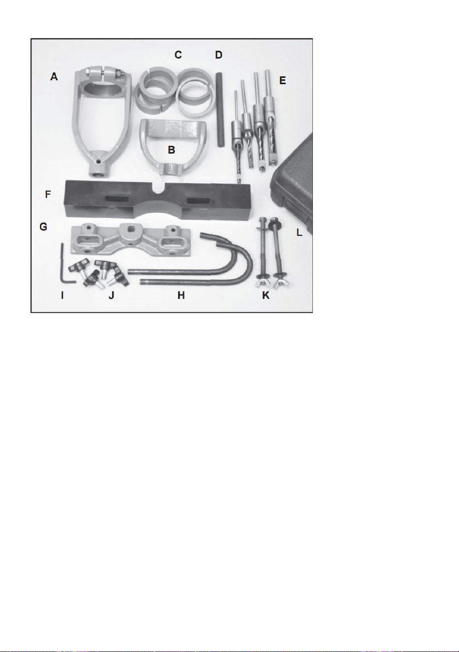
- 3 -
CN. Mejselhållare *1
CO. Håll ned Bracke *1
CP. Bussningar *4
CQ. Håll ned Rod *1
CR. Mejslar och borrskär (1/4, 5/8 , 3/8, 1/2) *4
CS. Staket *1
CT. Stånghållargjutning *1
CU. Böjda styrstänger *1
CV. Insexnyckel 4mm *1
CW. Stora vingmuttrar *4
CX. 5/16-18 x 4 sexkantsbultar *2
Brickor *4 vingmuttrar *2
CY. Bärväska med *1
CZ. Instruktioner (visas ej) *1

- 4 -
INSTALLATION INSTRUCTIONS
MONTERING PÅ BORPRESSBORDET.
Vi rekommenderar att du installerar en 1/2 plywoodpanel på
borrpressbordet.
Den kan hållas på plats genom att föra in den under stängslet. Borra
hål i plywood för att matcha slitsarna i bordet. Plywood kommer
förhindra skador på stämjärnet och borrkronan om det skulle behövas
träffa metallborrpressbordet av misstag. Det är också ett enkelt sätt att
öka storleken på borrpressbordet för att hålla dina projekt.
MONTERING AV MEJSELHÅLLARE.
15. Montera mejselhållaren (A) på eller precis ovanför basen av
borrpresspennan, med hållarens fästbult vänd utåt, bort från
borrpresskolonnen. För en korrekt passform kan en bussning (C) krävas
ska sättas in i mejselhållarens övre krage.
16. När det är installerat, dra åt muttern och bulten på mejselhållaren för
att förhindra att tillbehöret glider.
Installera tapp- och tappmejslar och borr.
15. Fyra storlekar av ihåliga stämjärn och bits (E) ingår
med satsen - 1/4", 5/8 " , 3/8" och 1/2". Använd endast rätt kombination
av mejslarna med motsvarande borrkrona. Dessa verktyg är
levereras från fabrik och MÅSTE slipas innan användning. Om antingen
en är matt, det blir överdriven friktion med värmeuppbyggnad, vilket
kommer att försvåra borrningen och skada verktygen. Rådfråga
träbearbetningsböcker eller tidningsartiklar om de rätta teknikerna för att

- 5 -
sätta skarpa kanter på dessa föremål.
16. Inga bussningar krävs för att installera borrspetsskaften i mejseln
hållarens krage, eftersom de båda har samma diameter. Skaftet på
mejseln kommer att hållas av den borrpressade chucken, precis som en
vanlig borrkrona skulle hållas.
INSTALLERA BETSEN OCH MEJSEL.
29. Sätt in borrkronan genom mejseln och in i borrpressen
kasta. Dra bara åt chucken för hand.
30. Sätt in mejseln i mejselhållaren och fäst den på plats med
vingmutter. OBS: Kläm fast mejseln så att dess skuldra är ungefär
1/32” under hållarens botten.
31. Skjut upp borrkronan i borrchucken så långt det går och fäst den
placera med chucknyckeln. Änden av borrkronan ska vara upp mot
änden av den fyrkantiga mejseln.
32. Lossa vingmuttern som håller fast mejseln och flytta mejseln uppåt till
ta upp det 1/32” utrymme som tidigare lämnades i steg 2. Dra åt mejseln
på plats. Denna metod säkerställer att det finns rätt spelrum mellan
borrkronans skärande läppar och mejselns spetsar.
När den används kommer den fyrkantiga mejseln att skära in i träet
och tvinga det skurna materialet inåt. Borrkronan skär sedan ut mitten av
hålet och riktar det mejselskurna materialet upp ur hålet i en enda
rörelse.
Sexkantsbultarna (K) som medföljer satsen är tillräckligt långa för att
kunna gå igenom
hållarfästet, staketet, plywood och borrpressbordet. Sätt in
sexkantsbult genom skårorna i varje. Använd brickor under
sexkantsbulten och under vingmuttern för att fördela hålltrycket.
MONTERA UNDERHÅLLARE.
15. Sätt in hållstången (D) i mitthålet på stavhållaren
Gjut (G) och fäst den på plats med sexkantsskruven. En 4 mm
insexnyckel (I) medföljer för detta.
16. Skjut nedhållningsfästet (B) nedåt på hållarstången. Hållet
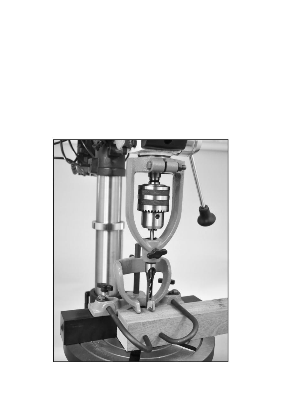
- 6 -
ner kan justeras upp och ner på stången efter behov för att applicera lätt
tryck ner på ditt arbete som borras. Denna konsol kommer att hålla ditt
projekt nere när stämjärnet och borrkronan släpps och dras ut ur hålet
som de borrade.
INSTALLERA DEN BÖJDA STYRSTAVEN.
15. Sätt in de två böjda styrstängerna (H) i de horisontella hålen som finns
på vardera sidan av stången som håller gjutningen, och fäst dem i
position med de medföljande vingmuttrarna.
16. Styrstängerna bör placeras på framsidan av ditt arbete, så
att de sätter tryck mot träet och trycker ditt projekt mot staketet.
Schematisk bild av den färdiga monteringen

- 7 -
UPPSTART.
22. Placera ditt arbetsstycke på borrpressbordet och justera bordets höjd
så att stämjärnet & biten är ca 1/2” ovanför verket.
23. Bestäm djupet på hålet som du vill skära och ställ in borren
tryck på djupstopp till detta avstånd.
24. Ställ in stängslets avstånd så att mejseln och biten är på den plats som
du
vill borra hålet.
Markera ditt arbetsstycke med den exakta platsen för hålen/hålen som
behöver borras.
Säkra ditt arbete på plats mot staketet med styrstängerna och även
med hållaren.
Flytta staketet in eller ut tills mejseln är perfekt i linje med
instickslinjerna som är markerade på ditt arbete.
Säkra staketet på plats med de två sexkantsbultarna som löper genom
gjutningen, staketet och borrpressbordet.
Drift.
43. Bästa borrpresshastigheter är mellan 650 till 1800 rpm.
44. Använd lägre hastigheter på lövträ.
45. Se till att mejseln är kvadratisk/parallell med staketet.
46. Provborra på skrot av samma träslag i ditt projekt för att ställa in
instickspositioner och borrpresshastighet.
47. Skär först utsidan, ändarna av urtaget och gör sedan överlappande
snitt
mellan de två för att avsluta insticken.
48. Höj mejseln ofta för att rensa spån och förhindra igensättning.

- 8 -
Sprängvy av produktdelen.
14
DELLISTA.
NYCKEL
NR
BESKRIVNING
NYCKEL
NR
BESKRIVNING
1
Mejselhållare
2
5/16-18 x 2-1/2” bult

- 9 -
3
5/16-18
Sexkantsmutter
4
Vingmutter med slittapp
5
Håll ned fäste
6
5/16-18 Vingmutter
7
Bricka
8
Böjda styrstänger
9
stav Håller gjutning
10
Håll ner stålstång
11
Staket
12
5/16-18 x 4” bult
13
Hexskruv
14
Bricka
15
Mejslar och borrskär (1/4, 5/ 8 , 3/8, 1/2) *4 (visas ej)
Obs: Specifikationer, foton, ritningar och information i denna bokhandbok
representerar den aktuella modellen vid den tidpunkt då manualen skrevs.
Ändringar och förbättringar kan göras när som helst utan förpliktelser
Ändring av tidigare levererade enheter av VEVOR.

- 10 -
Tillverkare: Shanghaimuxinmuyeyouxiangongsi
Adress : Shuangchenglu 803nong11hao1602A-1609shi, baoshanqu,
shanghai 200000 CN.
Importerad till AUS: SIHAO PTY LTD, 1 ROKEVA STREETEASTWOOD
NSW 2122 Australien
Importerad till USA: Sanven Technology Ltd., Suite 250, 9166 Anaheim
Place, Rancho Cucamonga, CA 91730

- 11 -
REP
EC
E-CrossStu GmbH
Mainzer Landstr.69, 60329 Frankfurt am Main.
REP
UK
YH CONSULTING LIMITED.
C/O YH Consulting Limited Office 147, Centurion House,
London Road, Staines-upon-Thames, Surrey, TW18 4AX