Safety • Assembly • Operation • Tips & Techniques • Maintenance • Troubleshooting • Parts Lists • Warranty
Warning: This unit is equipped with an internal combustion engine and should not be used on or near any unimproved forest-covered, brush-
covered or grass-covered land unless the engine’s exhaust system is equipped with a spark arrester meeting applicable local or state laws (if any).
If a spark arrester is used, it should be maintained in effective working order by the operator. In the State of California the above is required by law
(Section 4442 of the California Public Resources Code). Other states may have similar laws. Federal laws apply on federal lands. A spark arrester
for the muffler is available through your nearest engine authorized service dealer or contact the service department, P.O. Box 361131 Cleveland,
Ohio 44136-0019.
CUB CADET LLC, P.O. BOX 361131 CLEVELAND, OHIO 44136-0019
PRINTED IN U.S.A.
READ SAFETY RULES AND INSTRUCTIONS CAREFULLY BEFORE OPERATION
IMPORTANT
OPERATOR’S MANUAL
21-inch Self-Propelled Mower — Model Series 940
4/20/2007
FORM NO. 769-02318A

2
Finding and Recording Model Number
Table of Contents
BEFORE ASSEMBLING YOUR NEW EQUIPMENT,
please locate the model plate on the equipment and
copy the information to the sample model plate pro-
vided to the right. You can locate the model plate by
standing at the operating position and looking down
at the rear of the deck. This information will be neces-
sary to use the manufacturer’s web site, to obtain
assistance from the Customer Support Department,
or when contacting an authorized service dealer.
This Operator’s Manual is an important part of your new lawn mower. It will help you assemble,
prepare, and maintain the unit for best performance. Please read and understand what it says.
Please do NOT return the unit to the retailer from which it was purchased, without first
contacting Customer Support.
Customer Support
Slope Gauge........................................................ 3
Safe Operation Practices ................................... 4
Setup and Adjustment ....................................... 6
Operating Your Lawn Mower .............................. 8
Maintaining Your Lawn Mower ......................... 10
Troubleshooting ................................................ 14
Off-Season Storage and Safety Labels .......... 15
Parts List ........................................................... 16
If you have difficulty assembling this product or have any questions regarding the controls, operation, or maintenance of this
unit, you can seek help from the experts. Choose from the options below:
Cub Cadet LLC reserves the right to change product specifications, designs, and equipment without notice and without incurring obligation.
www.cubcadet.com
CUB CADET LLC
P. O. BOX
361131
CLEVELAND, OH 44136
DEALER LOCATOR PHONE NUMBER:
877-282-8684
• Visit www.cubcadet.com for many useful suggestions. Click on the Customer Service link and you will get several options
to help in answering your questions. Click on the appropriate button and help is immediately available.
• Phone our
Customer Service Department at 1(877) 428-2349.
• The
engine manufacturer is responsible for all engine-related issues with regards to performance, power-rating, specifica-
tions, warranty and service. Please refer to the engine manufacturer’s Owner’s/Operator’s Manual, packed separately with
your unit, for more information.
3
1
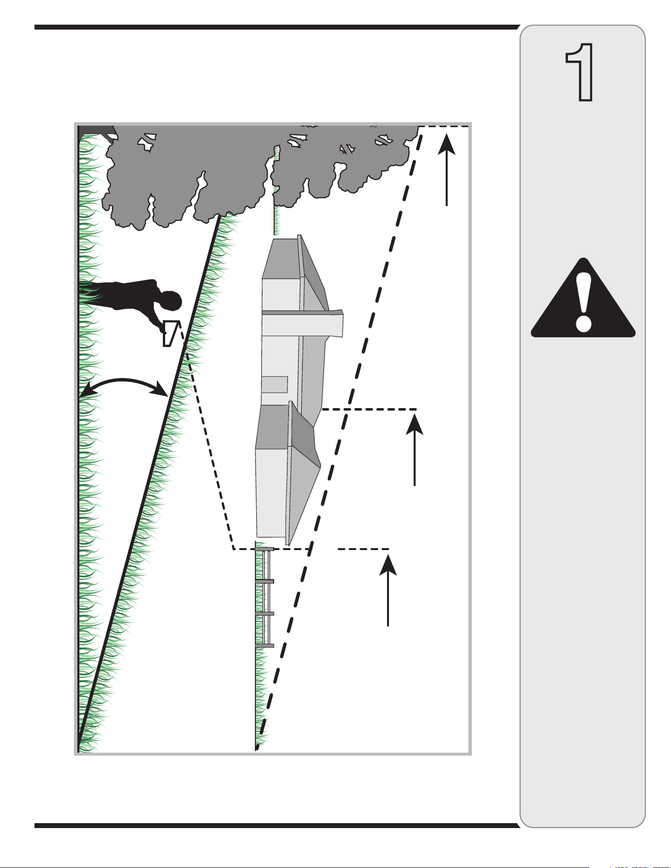
Slope
Gauge
WARNING
Do not mow on inclines
with a slope in excess
of 15 degrees (a rise
of approximately 2-1/2
feet every 10 feet).
Operate WALK-BEHIND
mowers across the
face of slopes, never
up and down slopes.
3IGHTANDHOLDTHISLEVELWITHAVERTICALTREE
ORACORNEROFABUILDING
ORAFENCEPOST
&OLDALONGDOTTEDLINEREPRESENTSASLOPE
Use this page as a guide to determine slopes where you may not operate safely.
Do not operate your lawn mower on such slopes.
4
2
Safe
Operation
Practices
Children
Tragic accidents can occur if operator is not alert to presence
of children. Children are often attracted to mower and mowing
activity. They do not understand the dangers. Never assume
that children will remain where you last saw them.
1. Keep children out of the mowing area and under watchful
care of a responsible adult other than the operator.
2. Be alert and turn mower off if a child enters the area.
3. Before and while moving backwards, look behind and down
for small children.
4. Use extreme care when approaching blind corners,
doorways, shrubs, trees, or other objects that may obscure
your vision of a child who may run into the mower.
5. Keep children away from hot or running engines. They can
suffer burns from a hot muffler.
6. Never allow children under 14 years old to operate a power
mower. Children 14 years old and over should read and
understand operation instructions and safety rules in this
manual and should be trained and supervised by a parent.
General Operation
1. Read this operator’s manual carefully in its entirety before
attempting to assemble this machine. Read, understand,
and follow all instructions on the machine and in the
manual(s) before operation. Be completely familiar with
the controls and the proper use of this machine before
operating it. Keep this manual in a safe place for future
and regular reference and for ordering replacement parts.
2. This machine is a precision piece of power equipment,
not a plaything. Therefore, exercise extreme caution at all
times. Your unit has been designed to perform one job: to
mow grass. Do not use it for any other purpose.
3. Never allow children under 14 years old to operate this
machine. Children 14 years old and over should read and
understand the instructions in this manual and should
be trained and supervised by a parent. Only responsible
individuals who are familiar with these rules of safe
operation should be allowed to use this machine.
4. Thoroughly inspect the area where the equipment is to
be used. Remove all stones, sticks, wire, bones, toys
and other foreign objects, which could be tripped over or
picked up and thrown by the blade. Thrown objects can
cause serious personal injury. Plan your mowing pattern
to avoid discharge of material toward roads, sidewalks,
bystanders and the like. Also, avoid discharging material
against a wall or obstruction, which may cause discharged
material to ricochet back toward the operator.
5. To help avoid blade contact or a thrown object injury,
stay in operator zone behind handles and keep children,
bystanders, helpers and pets at least 75 feet from mower
while it is in operation. Stop machine if anyone enters
area.
6. Always wear safety glasses or safety goggles during opera
-
tion and while performing an adjustment or repair to protect
your eyes. Thrown objects which ricochet can cause serious
injury to the eyes.
7. Wear sturdy, rough-soled work shoes and close-fitting
slacks and shirts. Shirts and pants that cover the arms and
legs and steel-toed shoes are recommended. Never operate
this machine in bare feet, sandals, slippery or light-weight
(e.g. canvas) shoes.
8. Do not put hands or feet near rotating parts or under cutting
deck. Contact with blade can amputate hands and feet.
9. A missing or damaged discharge cover can cause blade
contact or thrown object injuries.
10. Many injuries occur as a result of the mower being pulled
over the foot during a fall caused by slipping or tripping.
Do not hold on to the mower if you are falling; release the
handle immediately.
11. Never pull the mower back toward you while you are
walking. If you must back the mower away from a wall or
obstruction first look down and behind to avoid tripping and
then follow these steps:
a. Step back from mower to fully extend your arms.
b. Be sure you are well balanced with sure footing.
c. Pull the mower back slowly, no more than half way
toward you.
d. Repeat these steps as needed.
12. Do not operate the mower while under the influence of
alcohol or drugs.
13. Do not engage the self-propelled mechanism on units so
equipped while starting engine.
14. The blade control handle is a safety device. Never attempt
to bypass its operation. Doing so makes the safety device
inoperative and may result in personal injury through
contact with the rotating blade. The blade control handle
must operate easily in both directions and automatically
return to the disengaged position when released.
15. Never operate the mower in wet grass. Always be sure of
your footing. A slip and fall can cause serious personal
injury. If you feel you are losing your footing, release the
blade control handle immediately and the blade will stop
rotating within three seconds.
16. Mow only in daylight or good artificial light. Walk, never run.
17. Stop the blade when crossing gravel drives, walks or roads.
18. If the equipment should start to vibrate abnormally, stop the
engine and check immediately for the cause. Vibration is
generally a warning of trouble.
WARNING: Engine Exhaust, some of its constituents, and certain vehicle compo-
nents contain or emit chemicals known to State of California to cause cancer and
birth defects or other reproductive harm.
WARNING
This symbol points
out important safety
instructions which, if
not followed, could
endanger the personal
safety and/or property
of yourself and others.
Read and follow all
instructions in this
manual before at-
tempting to operate
this machine. Failure
to comply with these
instructions may result
in personal injury. When
you see this symbol.
HEED ITS WARNING!
Your Responsibility
Restrict the use
of this power machine
to persons who read,
understand
and follow the warnings
and instructions
in this manual
and on the machine.
DANGER: This machine was built to be operated according to the rules for safe operation in this
manual. As with any type of power equipment, carelessness or error on the part of the operator
can result in serious injury. This machine is capable of amputating hands and feet and throwing
objects. Failure to observe the following safety instructions could result in serious injury or death.

5
19. Shut the engine off and wait until the blade comes to a
complete stop before removing the grass catcher or unclog-
ging the chute.
The cutting blade continues to rotate for a few seconds after
the engine is shut off. Never place any part of the body in
the blade area until you are sure the blade has stopped
rotating.
20. Never operate mower without proper trail shield, discharge
cover, grass catcher, blade control handle or other safety
protective devices in place and working. Never operate
mower with damaged safety devices. Failure to do so can
result in personal injury.
21. Muffler and engine become hot and can cause a burn. Do
not touch.
22. Only use parts and accessories made for this machine by
manufacturer. Failure to do so can result in personal injury.
23. If situations occur which are not covered in this manual,
use care and good judgment. Contact your dealer for
assistance.
Slope Operation
Slopes are a major factor related to slip and fall accidents, which
can result in severe injury. Operation on slopes requires extra
caution. If you feel uneasy on a slope, do not mow it. For your
safety, use the slope gauge included as part of this manual to
measure slopes before operating this unit on a sloped or hilly
area. If the slope is greater than 15 degrees, do not mow it.
Do:
1. Mow across the face of slopes; never up and down. Exercise
extreme caution when changing direction on slopes.
2. Watch for holes, ruts, rocks, hidden objects, or bumps
which can cause you to slip or trip. Tall grass can hide
obstacles.
3. Always be sure of your footing. A slip and fall can cause
serious personal injury. If you feel you are losing your
balance, release the blade control handle immediately, and
the blade will stop rotating within 3 seconds.
Do Not:
1. Do not mow near drop-offs, ditches or embankments, you
could lose your footing or balance.
2. Do not mow slopes greater than 15 degrees as shown on
the slope gauge.
3. Do not mow on wet grass. Unstable footing could cause
slipping.
Service
Safe Handling Of Gasoline:
1. To avoid personal injury or property damage use extreme
care in handling gasoline. Gasoline is extremely flammable
and the vapors are explosive. Serious personal injury can
occur when gasoline is spilled on yourself or your clothes,
which can ignite. Wash your skin and change clothes
immediately.
2. Use only an approved gasoline container.
3. Never fill containers inside a vehicle or on a truck or trailer
bed with a plastic liner. Always place containers on the
ground away from your vehicle before filling.
4. Remove gas-powered equipment from the truck or trailer
and refuel it on the ground. If this is not possible, then refuel
such equipment on a trailer with a portable container, rather
than from a gasoline dispenser nozzle.
5. Keep the nozzle in contact with the rim of the fuel tank or
container opening at all times until fueling is complete. Do
not use a nozzle lock-open device.
6. Extinguish all cigarettes, cigars, pipes and other sources
of ignition.
7. Never fuel machine indoor because flammable vapors will
accumulate in the area.
8. Never remove gas cap or add fuel while engine is hot or
running. Allow engine to cool at least two minutes before
refueling.
9. Never over fill fuel tank. Fill tank to no more than ½ inch
below bottom of filler neck to provide for fuel expansion.
10. Replace gasoline cap and tighten securely.
11. If gasoline is spilled, wipe it off the engine and equipment.
Move unit to another area. Wait 5 minutes before starting
engine.
12. Never store the machine or fuel container near an open
flame, spark or pilot light as on a water heater, space
heater, furnace, clothes dryer or other gas appliances.
13. To reduce fire hazard, keep mower free of grass, leaves,
or other debris build-up. Clean up oil or fuel spillage and
remove any fuel soaked debris.
14. Allow a mower to cool at least 5 minutes before storing.
General Service:
1. Never run an engine indoors or in a poorly ventilated area.
Engine exhaust contains carbon monoxide, an odorless
and deadly gas.
2. Before cleaning, repairing, or inspecting, make certain the
blade and all moving parts have stopped. Disconnect the
spark plug wire and ground against the engine to prevent
unintended starting.
3. Check the blade and engine mounting bolts at frequent
intervals for proper tightness. Also, visually inspect blade
for damage (e.g., bent, cracked, worn) Replace blade with
the original equipment manufacture’s (O.E.M.) blade only,
listed in this manual. “Use of parts which do not meet the
original equipment specifications may lead to improper
performance and compromise safety!”
4. Mower blades are sharp and can cut. Wrap the blade or
wear gloves, and use extra caution when servicing them.
5. Keep all nuts, bolts, and screws tight to be sure the equip
-
ment is in safe working condition.
6. Never tamper with safety devices. Check their proper
operation regularly.
7. After striking a foreign object, stop the engine, discon
-
nect the spark plug wire and ground against the engine.
Thoroughly inspect the mower for any damage. Repair the
damage before starting and operating the mower.
8. Never attempt to make a wheel or cutting height adjust
-
ment while the engine is running.
9. Grass catcher components, discharge cover, and trail
shield are subject to wear and damage which could
expose moving parts or allow objects to be thrown. For
safety protection, frequently check components and re-
place immediately with original equipment manufacturer’s
(O.E.M.) parts only, listed in this manual. “Use of parts
which do not meet the original equipment specifications
may lead to improper performance and compromise
safety!”
10. Do not change the engine governor setting or over-rev the
engine. The governor controls the maximum safe operating
speed of the engine.
11. Maintain or replace safety labels, as necessary.
12. Observe proper disposal laws and regulations. Improper
disposal of fluids and materials can harm the environment.
2
Safe
Operation
Practices
WARNING
This symbol points
out important safety
instructions, which if
not followed, could
endanger the personal
safety and/or property
of yourself and others.
Read and follow all
instructions in this man-
ual before attempting to
operate this machine.
Failure to comply with
these instructions may
result in personal injury.
When you see this
symbol.
HEED IT’S WARNING!
Your Responsibility
Restrict the use
of this power machine
to persons who read,
understand
and follow the warnings
and instructions
in this manual
and on the machine.
6
3
Setup and
Adjustment
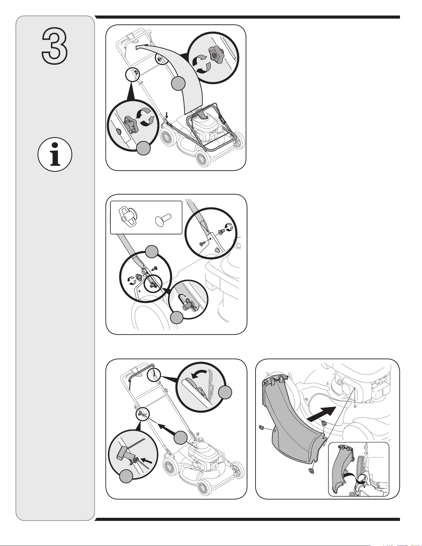
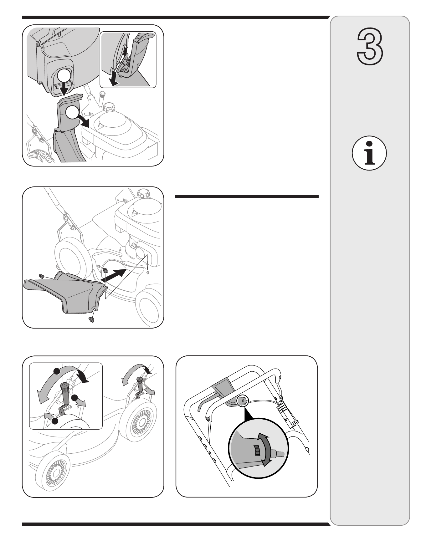
1. Remove any packing material which may be between
upper and lower handles.
a. Pull up and back on upper handle as shown in
Figure 3-1. Make certain the lower handle is seated
securely into the handle mounting brackets.
b. Tighten hand knobs to secure upper handle to
lower handle. Make sure that each carriage bolt is
seated properly in the handle.
2. Locate the hairpin clip on the weld pin on each side of
the lower handle.
a. Remove hairpin clip from this hole. Using a pair
of pliers, insert hairpin clip into the hole on pin
closest to the bracket. See Figure 3-2. Repeat on
other side.
b. Insert a carriage bolt from the hardware pack into
the upper hole on the handle mounting bracket.
Secure with one plastic wing nut, also included
in the hardware pack. Repeat on other side with
remaining items from hardware pack.
3. The rope guide, which is connected to the support
rod, is located on the right side of the lower handle.
See Figure 3-3.
a. Hold the blade control against upper handle.
b. Pull starter rope out of the engine. Release the
blade control.
c. Slip starter rope into rope guide.
4. Secure cables to the lower handle using the cable ties
already on the lower handle. Insert pegs on cable ties
into the holes on the lower handle. Pull cable ties tight
and trim excess.
NOTE: Stand behind
the mower as if you
were going to operate it.
Your right hand corre-
sponds to the right side
of the mower; your left
hand corresponds to the
left side of the mower.
IMPORTANT: This unit is
shipped without gasoline
or oil in the engine. Fill
up gasoline and oil as
instructed in the accom-
panying engine manual
BEFORE operating your
mower.
Figure 3-1: Unfold handle and tighten hardware.
Figure 3-2: Secure lower handle to mounting brackets.
Figure 3-3: Pull recoil starter through rope guide.
Figure 3-4: Use wing nuts to secure discharge chute to deck.
Wing Nuts (2)
Hardware Pack
Carriage Bolts (2)
A
B
A
B
C
Handle
Mounting
Bracket
A
B
7
CUTTING HEIGHT
All wheels must be set
to the same height. For
rough or uneven lawns,
use a higher cut setting.
3
Setup and
Adjustment
Adjustments
1. The cutting height adjustment lever is located above
the rear left wheel. See Figure 3-7.
a. Pull the lever out and away from the mower.
b. Move the lever forward or back for desired cutting
height.
c. Release lever towards mower deck.
2. The adjustment wheel is located in the drive control
handle housing and is used to tighten or loosen the
drive belt. You will need to adjust the drive control
if the mower does not propel itself with the drive
control engaged or if the drive wheels hesitate with
the drive control engaged.
If either of these conditions occur, rotate the adjust-
ment wheel to adjust the drive control, Figure 3-8.
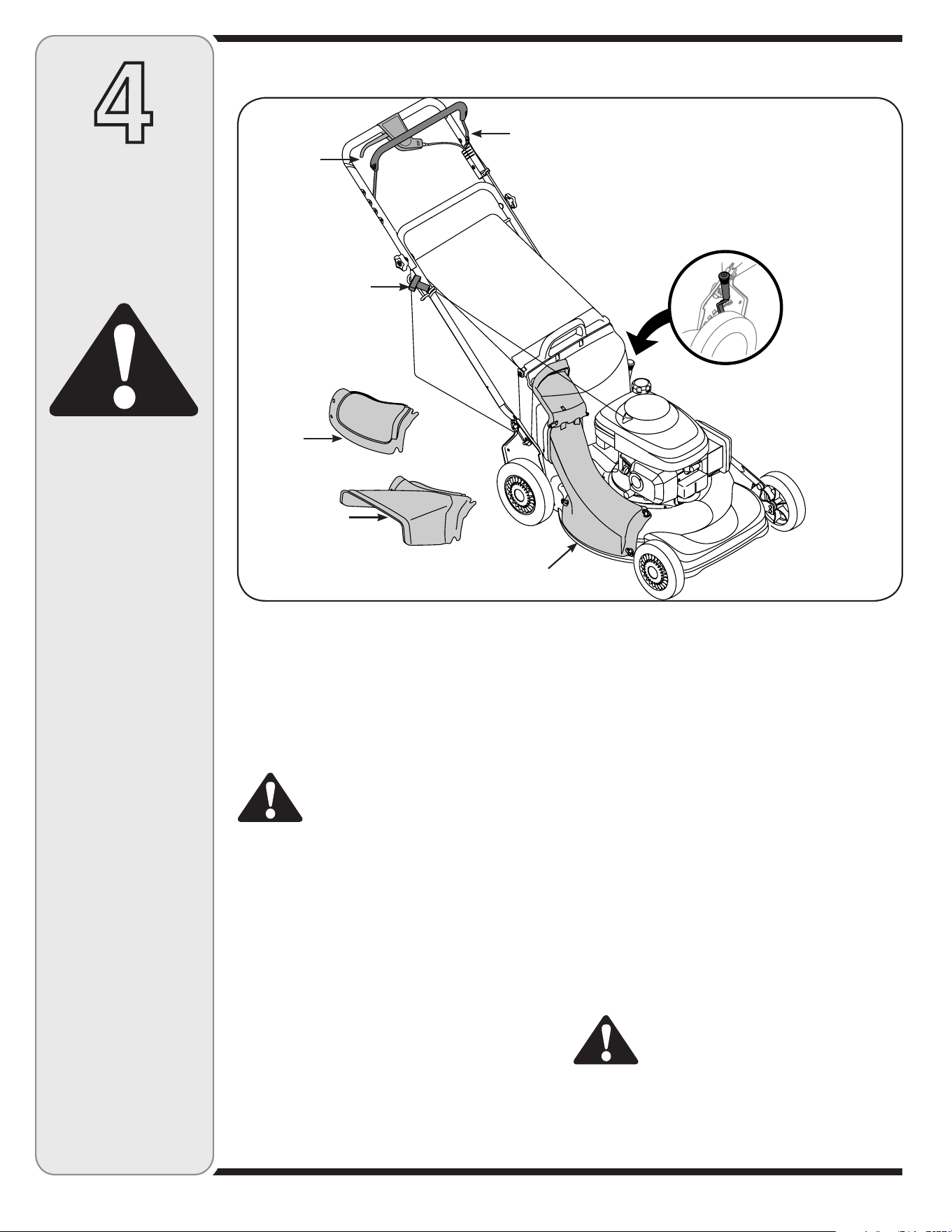
5. The mower was shipped with the mulching cover
installed on the unit. For bagging purposes, you will
need to attach the discharge chute and grass bag in
place of the mulching baffle.
a. Remove three wing nuts holding the mulching
cover in place and remove the cover.
b. Replace with discharge chute, while making sure
the front lip of chute goes under the edge of the
deck. Secure with wing nuts previously removed.
See Figure 3-4.
c. Lift chute door on the discharge chute and slide
grass bag onto the chute. See Figure 3-5.
6. Follow the steps below to install the side discharge
chute:
a. Remove mulching cover or grass bag from unit
by disconnecting wing nuts.
b. Attach side discharge chute to unit and secure
with the three wing nuts. See Figure 3-6.
Figure 3-5: Attach the grass bag to discharge chute.
Figure 3-6: Remove mulching cover or grass bag before install-
ing side discharge chute.
Figure 3-7: Use lever to adjust the cutting height.
Figure 3-8: Use the adjustment wheel on the drive control to
adjust the drive belt.
NOTE: Make certain
the cables are routed
around the handles so
as to not interfere with
attaching the grass bag.
A
B
A
B
C
Loosen
Tighten
8
4
Operating
Your Lawn
Mower
Blade Control
The blade control is attached to the upper handle of
the mower. Depress and squeeze it against the upper
handle to engage the engine and blade. Release it to
stop engine and blade.
WARNING: This blade control is a safety
device. Do not bypass its operations.
Drive Control
The drive control is located on the upper handle.
Squeeze the drive control lever to engage the drive
system. Release it to disengage the drive system.
Release the drive control to slow down when approach-
ing an obstacle, making a turn, or stopping.
Cutting Height Adjustment Lever
The cutting height adjustment lever is located above
the left rear wheel. Refer to the Setup and Adjustment
section for instructions on adjusting the cutting height.
Recoil Starter
The recoil starter is connected to the support rod and
is located on the right side of the lower handle. Stand
behind the unit and pull the recoil starter rope to start
the engine.
Mulch Cover
To use the mower as a mulcher, remove the discharge
chute and install the mulch cover.
Side Discharge Chute
Instead of collecting grass clippings in the bag, you may
attach the side discharge chute to expel the clippings.
Discharge Chute
The discharge chute must be attached to the deck to use
the grass bag.
Gas and Oil Fill-Up
Refer to engine manual for engine instructions.
1. Check oil level and add oil if necessary. Follow engine
manual for this.
2. Service the engine with gasoline as instructed in the
engine manual.
WARNING: Use extreme care when
handling gasoline. Gasoline is extremely
flammable and the vapors are explosive.
Never fuel the machine indoors or while the engine is
hot or running. Extinguish cigarettes, cigars, pipes
and other sources of ignition.
WARNING
The blade control
is a safety device.
DO NOT attempt to
bypass its operation.
Use extreme care
when handling
gasoline. Gasoline is
extremely flammable
and the vapors are
explosive. Never fuel
the machine indoors
or while the engine
is hot or running.
Extinguish cigarettes,
cigars, pipes and
other sources of
ignition.
Know Your Lawn Mower
Now that you have set up your lawn mower, it’s important to become acquainted with its controls and features.
Figure 4-1: The major components on the mower.
IMPORTANT: This unit is
shipped without gasoline or
oil in the engine. Fill up gas-
oline and oil as instructed in
the accompanying engine
manual BEFORE operating
your mower.
Recoil Starter
Mulch Cover
Side Discharge
Chute
Discharge Chute
Height Adjustment Lever
Drive Control
Blade Control
9
4
Operating
Your Lawn
Mower
WARNING
The operation of any
lawn mower can result
in foreign objects
being thrown into
the eyes, which can
damage your eyes
severely. Always wear
safety glasses while
operating the mower,
or while performing
any adjustments or
repairs on it.
Be sure no one other
than the operator is
standing near the lawn
mower while starting
engine or operating
mower. Never run
engine indoors or
in enclosed, poorly
ventilated areas. En-
gine exhaust contains
carbon monoxide, an
odorless and deadly
gas. Keep hands,
feet, hair and loose
clothing away from
any moving parts
on engine and lawn
mower.
WARNING: The operation of any lawn
mower can result in foreign objects being
thrown into the eyes, which can damage
your eyes severely. Always wear safety glasses while
operating or maintaining the mower.
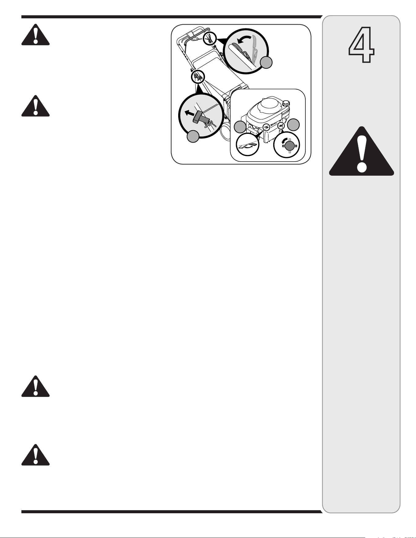
Starting Engine
WARNING: Be sure no one other than the
operator is standing near the lawn mower
while starting engine or operating mower.
Never run engine indoors or in enclosed, poorly
ventilated areas. Engine exhaust contains carbon
monoxide, an odorless and deadly gas. Keep hands,
feet, hair and loose clothing away from any moving
parts on engine and lawn mower.
1. Place the fuel valve lever found on the left side of the
engine into the ON (OPEN) position. See Figure 4-2.
2. Move the choke lever all the way backward into the
choke position. See Figure 4-2.
3. Standing behind the mower, squeeze the blade control
against upper handle. The choke will now begin to
slowly return to the off choke position after activating
the blade control. Therefore, quickly move onto step
four below. Refer to the engine manual for further
details.
4. Holding these two handles together firmly, grasp recoil
starter handle and pull rope out with a rapid, continu-
ous, full arm stroke. See Figure 4-2. Keeping a firm
grip on the starter handle let the rope rewind slowly.
Repeat until engine cranks. Let the rope rewind each
time slowly.
Stopping Engine
1. Release blade control to stop the engine and blade.
2. Disconnect spark plug wire from spark plug and
ground against the engine.
Using Your Lawn Mower
WARNING: Do not operate mower without
mulching cover, discharge chute, or grass
catcher properly installed.
Be sure lawn is clear of stones, sticks, wire, or other
objects which could damage lawn mower or engine.
Such objects could be accidently thrown by the mower
in any direction and cause serious personal injury to the
operator and others.
WARNING: If you strike a foreign object,
stop the engine. Remove wire from the
spark plug, thoroughly inspect mower
for any damage, and repair damage before restarting
and operating. Extensive vibration of mower during
operation is an indication of damage. The unit should
be promptly inspected and repaired.
1. Once the engine is running, squeeze the drive
control lever to propel the mower. For best results,
do not cut wet grass and never cut off more than
one-third of the total length of the grass.
Using as a Mulcher
For mulching grass, remove the grass catcher and
chute from the mower. Reattach mulch cover. Refer to
Setup section for instructions.
• For effective mulching, do not cut wet grass.
• New or thick grass may require a narrower cut.
Adjust ground speed according to condition of lawn.
• If the grass has been allowed to grow in excess of
four inches, mulching is not recommended. Use the
grass catcher to bag clippings instead.
Using the Grass Catcher
You can use the grass catcher to collect clippings while
you are operating the mower.
1. Attach grass catcher following instructions in Setup
section. Grass clippings will automatically collect in
the bag as you run the mower. Operate the mower till
the grass bag is full.
2. Stop engine completely by releasing the blade
control. Make sure that the unit has come to a
complete stop.
3. While holding the grass bag by both the rear handle
and the lower handle, lift the grass bag straight up
off the discharge chute. The chute door will move the
rope out of the way of the bag.
4. Continue to hold the lower handle and raise the rear
of the grass bag up towards your chest. The grass
bag will open and the grass clippings will disperse.
When replacing the grass bag, be sure the top of the
bag rests on the wire support between the handles.
Figure 4-2: The steps involved in starting the mower.
ON
OFF
1
2
3
4
10
5
Maintaining
Your Lawn
Mower
WARNING
Always stop engine,
disconnect spark
plug and ground
against engine be-
fore performing any
type of maintenance
on your machine.
IMPORTANT: Do not use a
pressure washer or garden
hose to clean your unit.
These may cause damage
to pulleys, bearings, or the
engine. The use of water will
result in shortened life and
reduce serviceability.
General Recommendations
• Always observe safety rules when performing
any maintenance.
• The warranty on this lawn mower does not cover
items that have been subjected to operator abuse
or negligence. To receive full value from warranty,
operator must maintain the lawn mower as
instructed here.
• Changing of engine-governed speed will void
engine warranty.
• All adjustments should be checked at least once
each season.
• Periodically check all fasteners and make sure these
are tight.
WARNING: Always stop engine, discon-
nect spark plug, and ground against
engine before cleaning, lubricating or
doing any kind of maintenance on your machine.
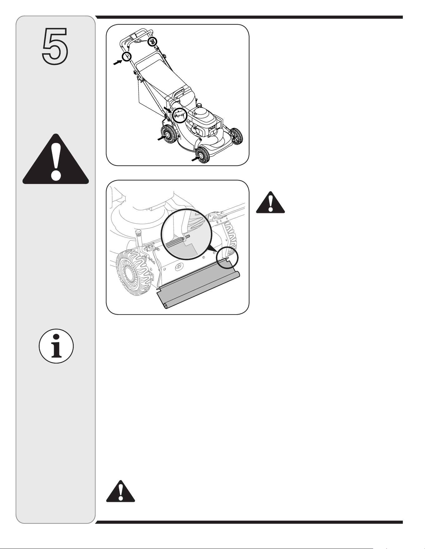
Lubrication
• Lubricate pivot points on the blade control at least
once a season with light oil. The blade control must
operate freely in both directions. See Figure 5-1.
• Lubricate the wheels at least once a season with
light oil (or motor oil). If wheels are removed for any
reason, lubricate the axle bolt and inner surface of the
wheel with light oil.
• Lubricate the torsion spring and pivot point on each
end of the discharge chute at least once a season with
light oil to prevent rust.
• The transmission is pre-lubricated and sealed at the
factory and does not require lubrication.
• Follow the accompanying engine manual for lubrica-
tion schedule and instruction for engine lubrication.
Deck Care
WARNING: Never tip the mower more
than 90º in any direction and do not
leave the mower tipped for any length of
time. Oil can drain into the upper part of the engine
causing a starting problem.
1. Disconnect spark plug wire. Drain gasoline from lawn
mower or place a piece of plastic under the gas cap.
2. Tip mower so that it rests on the housing. Keep the
side with the air cleaner facing up. Hold mower firmly.
3. Scrape and clean the underside of the deck with a
suitable tool. Do not spray with water.
4. Put the mower back on its wheels on the ground. If
you had put plastic under the gas cap earlier, make
sure to remove it now.
Engine Care
• Maintain oil level as instructed in engine manual.
• Service air cleaner every 25 hours under normal
conditions. Clean every few hours under extremely
dusty conditions. Refer to engine manual.
• Clean spark plug and reset the gap once a season.
Check engine manual for correct plug type and gap
specifications.
• Clean engine regularly with a cloth or brush. Keep the
cooling system (blower housing area) clean to permit
proper air circulation. Remove all grass, dirt and
combustible debris from muffler area.
Replacing Rear Flap
1. Cut off the flat end of the wire rod which secures it to
the deck. See Figure 5-2.
2. Attach the new flap and new rod to the deck, bending
the ends of the new rod over to secure to deck.
Figure 5-1: Areas to lubricate on the mower.
Figure 5-2: Cut wire to remove rear flap.
11
5
Maintaining
Your Lawn
Mower
WARNING
Blade Care
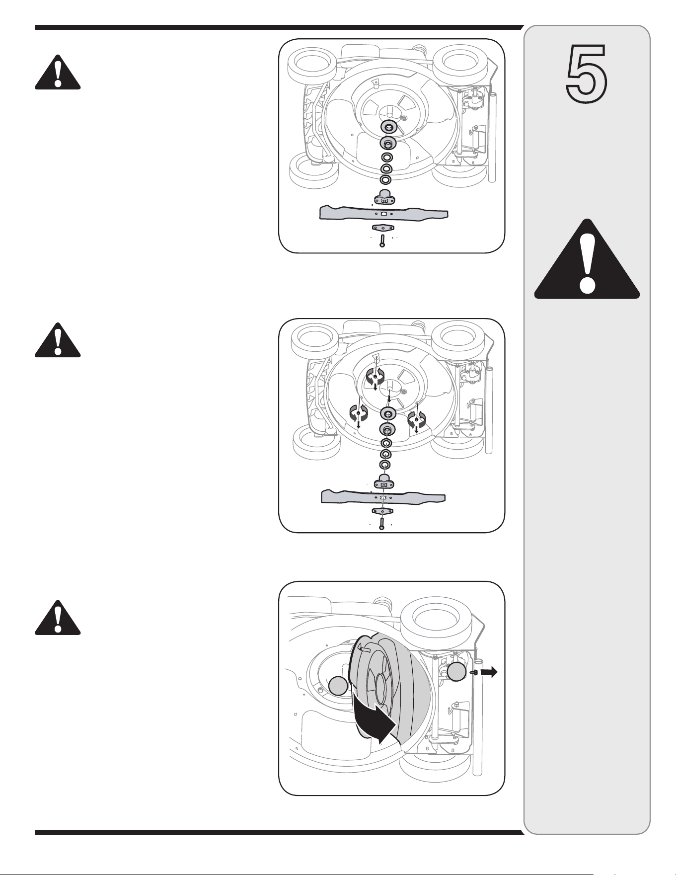
WARNING: When removing cutting blade
for sharpening or replacement, protect
your hands with a pair of heavy gloves or
use a heavy rag to hold blade.
1. Disconnect spark plug wire from spark plug. Turn
mower on its side making sure that the air filter and
carburetor are facing up.
2. Remove bolt, bell blade support, blade, and blade
adapter from the engine crankshaft. See Figure 5-3.
When removing these items, the pulleys and
washers may also break free from the crankshaft.
Be sure to make note of the orientation of these
items for reassembly.
3. The blade can be sharpened with a file or on a
grinding wheel. Do not attempt to sharpen the blade
while it is still on the mower. Balance the blade on a
round shaft screwdriver. Grind cutting edges equally
and follow the original angle of grind. Remove metal
from the heavy side until it balances evenly.
WARNING: An unbalanced blade will
cause excessive vibration when rotating
at high speeds. It may cause damage to
mower and could break causing personal injury.
4. Lubricate the engine crankshaft and the inner surface
of the blade adapter with light oil. Reinsert the spacer
(if needed), pulleys and washers. Slide the blade
adapter onto the engine crankshaft. Place the blade
on the adapter such that the side of the blade marked
“Bottom” (or with part number) faces the ground when
the mower is in the operating position. Make sure that
blade is aligned and seated on blade adapter flanges.
5. Place bell blade support on the blade. Align notches
on the bell blade support with small holes in blade.
Replace hex bolt and tighten hex bolt to torque: 450
in. lbs. min., 600 in. lbs. max.
To ensure safe operation of your mower, periodically
check the blade bolt for correct torque.
Belt Care
WARNING: When removing the cutting
blade or when sliding the belt around it,
protect your hands with a pair of heavy
gloves.
Removing the Belt
1. Disconnect the spark plug wire and ground it against
the engine.
2. Drain the fuel tank or place a piece of plastic beneath
the cap to prevent gasoline leakage.
3. Tip mower on its side (air cleaner side of engine up).
4. Move height adjustment lever to the highest position.
5. Remove blade, blade adapter, and related hardware.
Be sure to make note of the orientation of these
items for reassembly. Remove the three hex screws
holding baffle to the deck. See Figure 5-4.
An unbalanced blade
will cause excessive
vibration when rotat-
ing at high speeds. It
may cause damage
to mower and could
break causing per-
sonal injury.
When removing
the cutting blade
for sharpening or
replacement or
when sliding the belt
around it, protect
your hands with a
pair of heavy gloves
or use a heavy rag to
hold the blade.
Figure 5-3: To access blade, remove the bolt, support, blade,
and adapter.
Figure 5-4: Remove blade, hardware, and baffle screws.
Figure 5-5: Peel back baffle (A) and loosen screw holding
transmission to deck. (B)
A
B
12
5
Maintaining
Your Lawn
Mower
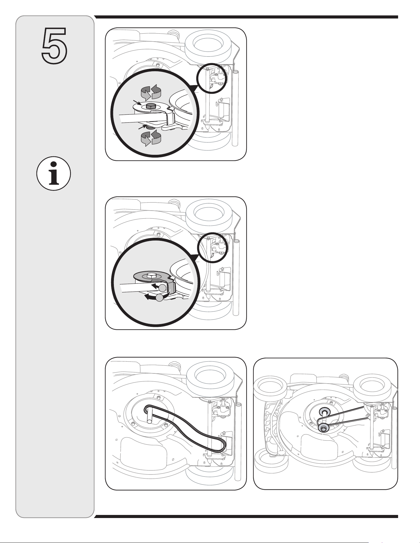
NOTE: When replacing
belt, It is important that the
belt is routed within the
inside of the belt keeper rod
attached to the underside
of the baffle.
Figure 5-6: Loosen bolt and nut on belt keeper and idler
bracket.
Figure 5-7: Rotate belt keeper to free the belt.
Figure 5-8: Remove belt from crankshaft after freeing it from
the transmission pulley.
Figure 5-9: Place upper pulley on crankshaft, loop belt around
crankshaft, then install the lower pulley.
6. Lift baffle towards the rear of the mower. Remove the
hex bolt that holds the transmission to the mower deck
from the rear of unit. See Figure 5-5.
7. Tilt the transmission forward to make it easier to work
in this area.
8. Loosen the belt keeper bolt and lock nut half a turn.
See Figure 5-6.
9. Using a pair of pliers, pull back and rotate belt keeper
from the slot on the idler bracket. See Figure 5-7.
10. Slide the belt out from between the belt keeper and
the idler bracket.
11. Slide the belt out from around the pulley on the
transmission.
12. Remove belt from around the crankshaft. See Figure
5-8. Discard the worn belt.
Installing the Belt
13. Place the new belt over the transmission pulley. Place
the belt in the pulley groove and rotate the pulley until
the belt is seated in transmission pulley.
14. Place the belt between the idler bracket and the belt
keeper.
15. Using pliers, rotate the belt keeper so that it snaps into
slot on the idler bracket.
16. Tighten the belt keeper bolt and lock nut.
17. Reinstall the screw that secures the transmission to
the mower deck.
18. Place the belt between the two pulley halves on the
crankshaft. See Figure 5-9.
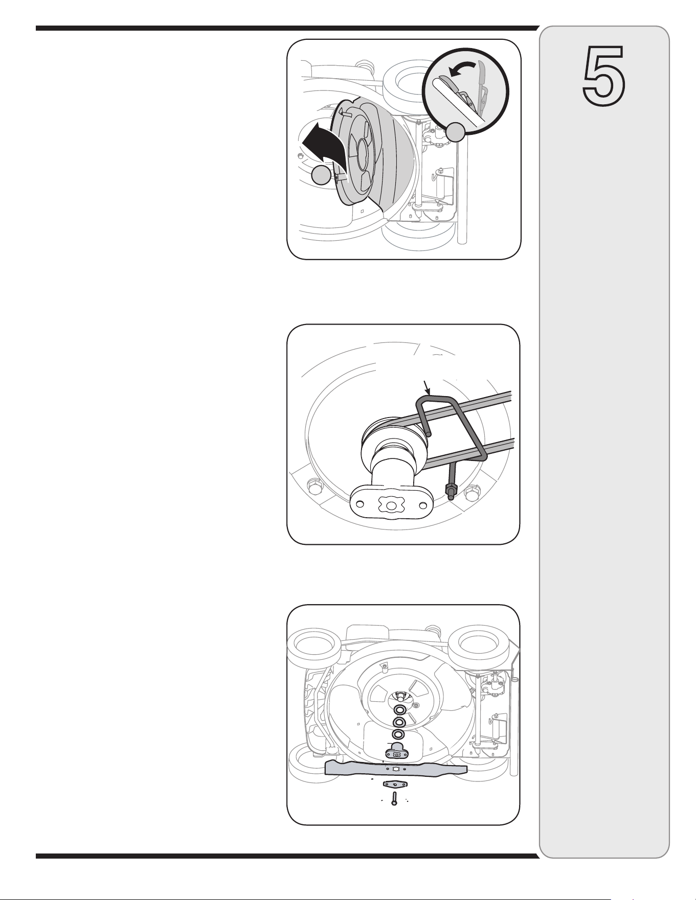
19. Squeeze the blade control against the upper handle
to tighten the belt. Return baffle back to its original
position and release the blade control. See Figure
5-10.
A
B
Idler
Bracket
Belt
Keeper
13
5
Maintaining
Your Lawn
Mower
NOTE: It is important that the belt is routed within the
inside of the belt keeper rod attached to the underside of
the baffle. See Figure 5-11.
20. Secure the baffle to deck using the three screws
removed earlier.
21. Lightly lubricate the inside of the blade adapter and
reinstall the washers, blade adapter, blade, and blade
bell support in the correct order. See Figure 5-12
(Refer to Blade Care section). Tighten the hex bolt to
450-600 in. lbs. torque.
Off-Season Storage
The following steps should be taken to prepare your lawn
mower for storage.
• Clean and lubricate mower thoroughly as described
in the lubrication instructions. Do not use a pressure
washer or garden hose to clean your unit.
• Refer to engine manual for correct engine storage
instructions.
• Coat mower’s cutting blade with chassis grease to
prevent rusting.
• Store mower in a dry, clean area. Do not store next to
corrosive materials, such as fertilizer.
When storing any type of power equipment in a poorly
ventilated or metal storage shed, care should be taken to
rust-proof the equipment. Using a light oil or silicone, coat
the equipment, especially cables and all moving parts of
your lawn mower before storage.
Figure 5-10: Engage the blade control to tighten the belt (A)
and place baffle back onto deck (B).
Figure 5-11: The belt should be routed to the inside of the belt
keeper rod.
Figure 5-12: Reinstall the remaining hardware.
A
B
Belt Keeper Rod (attached
to underside of baffle)
14
For repairs beyond
the minor adjustments
listed here, contact
an authorized service
dealer.
6
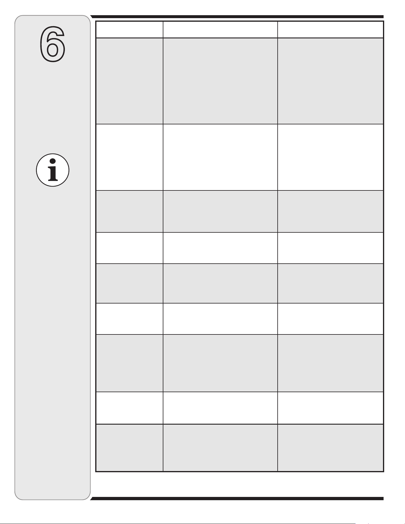
Trouble
Shooting
Cause
Problem
Remedy
Engine fails to start
1. Blade control disengaged.
2. Spark plug wire disconnected.
3. Fuel tank empty or stale fuel.
4. Engine not primed (if equipped with
primer).
5. Faulty spark plug.
6. Blocked fuel line.
7. Engine flooded.
8. Fuel valve (if equipped) closed.
9. Engine not choked (if equipped w/choke).
1. Engage blade control.
2. Connect wire to spark plug.
3. Fill tank with clean, fresh gasoline.
4. Prime engine as instructed in “Operat
-
ing Your Lawn Mower”.
5. Clean, adjust gap, or replace.
6. Clean fuel line.
7. Wait a few minutes to restart, but do
not prime.
8. Open fuel valve. See engine manual.
9. Choke engine. See engine manual.
Engine runs erratic
1. Connect and tighten spark plug wire.
2. Clean fuel line; fill tank with clean,
fresh gasoline.
3. Clear vent.
4. Drain fuel tank. Refill with fresh fuel.
5. Refer to engine manual.
6. Refer to engine manual.
1. Spark plug wire loose.
2. Blocked fuel line or stale fuel.
3. Vent in gas cap plugged.
4. Water or dirt in fuel system.
5. Dirty air cleaner.
6. Carburetor out of adjustment.
Engine overheats
1. Fill crankcase with proper oil.
2. Remove blower housing
and clean.
3. Refer to engine manual.
1. Engine oil level low.
2. Air flow restricted.
3. Carburetor not adjusted properly.
Occasional skips
(hesitates) at
high speed
1. Adjust gap to .030”.
2. Refer to engine manual.
1. Spark plug gap too close.
2. Carburetor idle mixture adjustment
improperly set.
Idles poorly
1. Reset gap to .030” or replace
spark plug.
2. Refer to engine manual.
3. Refer to engine manual.
1. Spark plug fouled, faulty or gap
too wide.
2. Carburetor improperly adjusted.
3. Dirty air cleaner.
Mower will not
mulch grass (If
Equipped)
1. Do not mow when grass is wet; wait
until later to cut.
2. Mow once at a high cutting height,
then mow again at desired height or
make a narrower cutting path.
3. Sharpen or replace blade.
1. Wet grass.
2. Excessively high grass.
3. Dull blade.
Uneven cut
1. Place all four wheels in same
height position.
2. Sharpen or replace blade.
1. Wheels not positioned correctly.
2. Dull blade.
Excessive
Vibration
1. Cutting blade loose or unbalanced.
2. Bent cutting blade.
1. Tighten blade and adapter. Balance
blade.
2. See an authorized service dealer.
Mower will not
self propel
1. Check belt for proper pulley installation
and movement.
2. Stop engine, disconnect spark plug
wire and clean out debris.
3. Inspect and replace belt.
1. Belt not installed properly.
2. Debris clogging drive operation.
3. Damaged or worn belt.
15
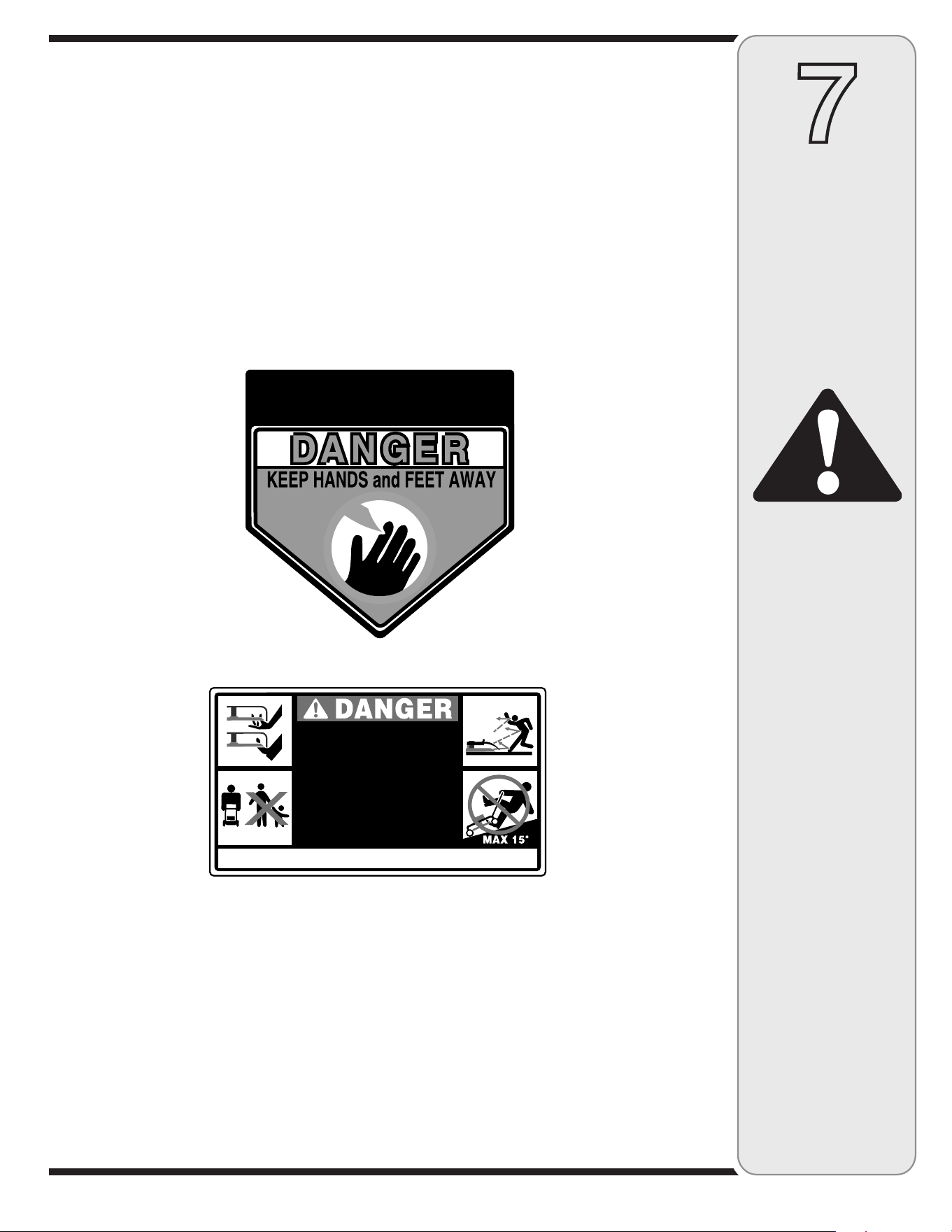
7
WARNING
DO NOT remove safety
(or any) labels from
mower for any reason.
Safety Labels Found On Your Lawn Mower
Safety
Labels
TO REDUCE THE RISK OF INJURY, DO NOT
OPERATE UNLESS DISCHARGE COVER OR
GRASS CATCHER IS IN ITS PROPER PLACE.
IF DAMAGED, REPLACE IMMEDIATELY.
HT
A
E
D
RO YRUJNI SUOIRES DIOVA
MORF YAWA TEEF DNA SDNAH PEEK •
.STRAP GNITATOR
•
NWORHT EB NAC TAHT STCEJBO EVOMER
.NOITCERID YNA NI EDALB EHT YB
.SESSALG YTEFAS RAEW
SREHTO RO NERDLIHC NEHW WOM TON OD •
.DNUORA ERA
•
WOM TON OD .SEPOLS NO NOITUAC ARTXE ESU
REVEN SSORCA WOM .˚51 NAHT RETAERG SEPOLS
OT ESOLC REWOM LLUP REVEN .NWOD DNA PU
EROFEB DNIHEB DNA NWOD KOOL .TEEF RUOY
.SDRAWKCAB GNIVOM ELIHW DNA
,DLEIHS GNILIART ,LORTNOC EDALB( SECI
V
ED YTEFAS PEEK . LAUNAM S'ROTAREPO DAER
.YLETA
I
D
E
MM
I
ECA
L
PER
,DEGAMAD FI .GNIKROW DNA ECALP NI ).CT
E
,
R
EVOC EGRAHCSID
16
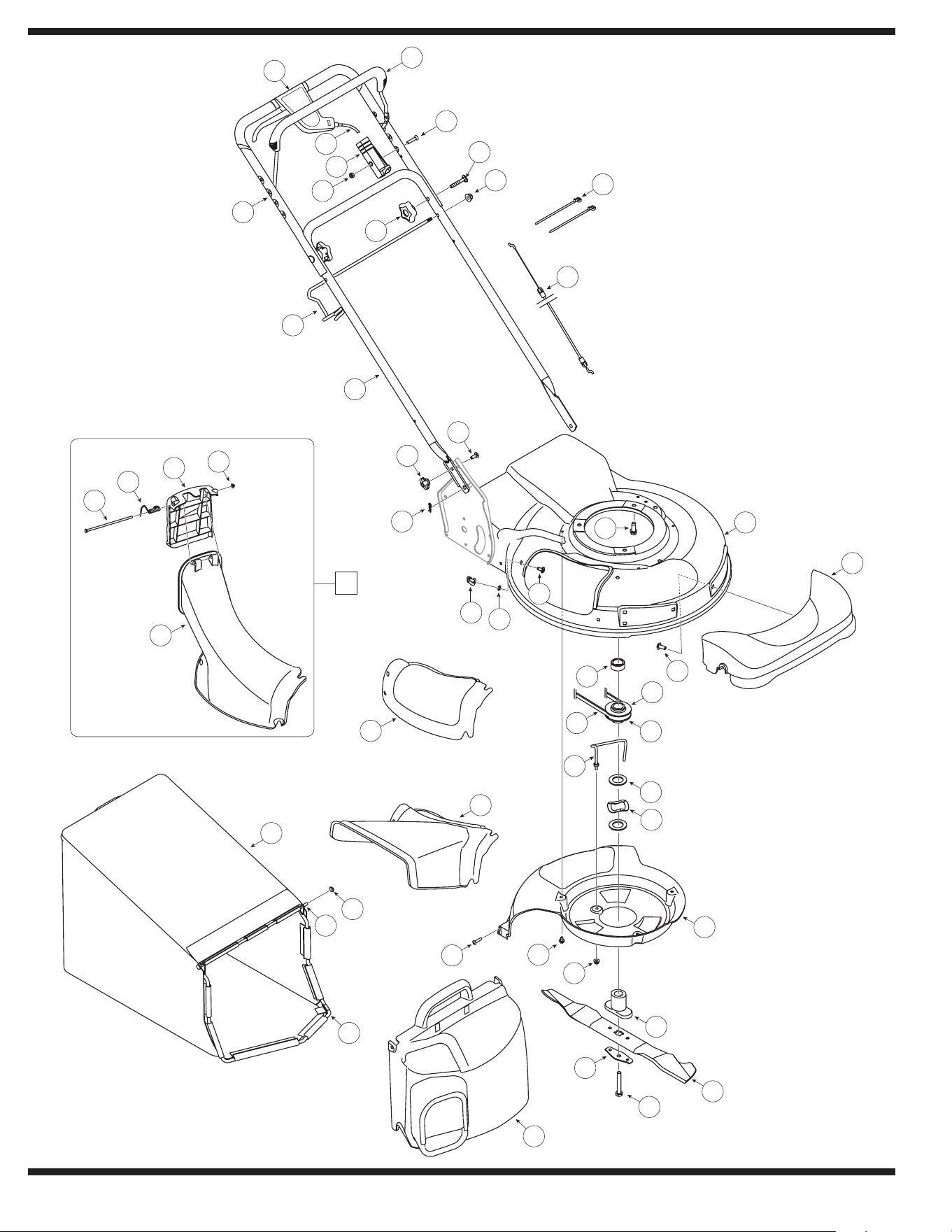
Model Series 940
48
49
50
34
46
45
36
37
38
39
35
40
44
41
32
43
2
1
47
3
5
7
27
10
8
26
25
24
23
19
11
30
6
29
32
31
33
43
28
22
18
20
21
12
13
14
15
16
17
9
4
42
17
Parts List
8
IMPORTANT: For a proper
working machine, use
Factory Approved Parts.
V-BELTS are specially
designed to engage
and disengage safely.
A substitute (non-OEM)
V-Belt can be dangerous
by not disengaging
completely.
To order replacement
parts, call 1-877-428-
2349, or visit
www.cubcadet.com to
find the nearest Cub
Cadet service dealer in
your area.
G
E
N
U
I
N
E
F
A
C
T
O
R
Y
P
A
R
T
S
Ref. Part No. Description
1 647-04008 Lever Assembly
2 710-1270 Machine Screw, 1/4-20 x 1.310
3 712-04063 Flange Lock Nut, 5/16-18
4 726-0240 Cable Tie
5 746-0557 Control Cable, 47-inch
6 710-0654A TT Screw, 3/8-16 x 1.00
7 782-0078B 21-inch Deck
8 731-1836 Front Axle Cover
9 710-1242 HL Screw, 5/16-14 x .750
10 756-04161 Upper Half Pulley
11 756-04160 Key Half Pulley
12 736-0277 Flat Wash., 1.031 x 1.620 x .095
13 736-0447 Wave Wash., 1.5 x 1.0 x .029
14 731-1828 Rear Baffle
15 748-04082 Blade Adapter
16 742-0741 21-inch Mulching Blade
17 710-1257 HH Cap Screw, 3/8-24 x 2.50
18 736-0524B Bell Blade Spacer
19 631-0071 Grass Bag Cover Assembly
20 712-04064 Flange Lock Nut 1/4-20
21 710-0653 TT Screw 1/4-20 x .375
22 710-0895 HL Screw 1/4-15 x .75
23 747-0937 Grass Bag Frame
24 747-0939 Grass Bag Pivot Rod
25 726-0106 Cap Speed Nut
Ref. Part No. Description
26 664-0180 Grass Bag Assembly
27 731-1832 Side Discharge Chute
28 747-04451 Belt Keeper Rod
29 754-0460 V-Belt
30 750-04438A Sleeve Spacer
31 731-1833A Mulch Cover
32 712-0397 Wing Nut
33 726-0233 Push Nut
34 749-0439D Upper Handle
35 731-1713B Top Discharge Chute
36 747-0965 Chute Door Pivot Rod
37 732-0819 Torsion Spring
38 731-1874 Top Discharge Door Chute
39 726-0111 Push Cap
40 631-0066 Top Discharge Chute Assembly
41 714-0104 Cotter Pin
42 753-0833 Drive Control Assembly
43 710-0703 Carriage Screw 1/4-20 x .75
44 749-0907B Lower Handle
45 747-0940A Grass Bag Support Rod
46 720-04072 Star Knob
47 710-1174 Carriage Bolt 5/16-18 x 2
48 712-0324 Hex Lock Nut 1/4-20
49 746-0883 ERS Housing
50 746-0711B 51-inch Cable
18
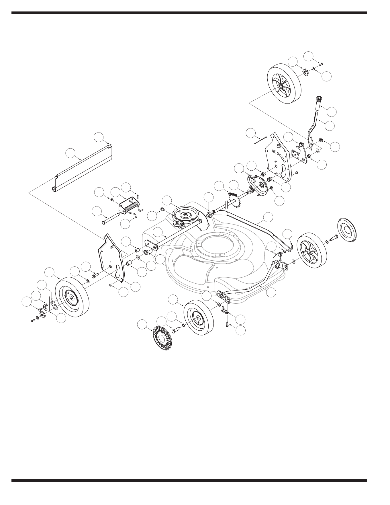
Model Series 940
3
1
2
4
6
7
8
50
5
49
48
47
46
44
43
45
12
10
9
41
11
14
18
19
17
16
15
99
24
23
22
20
32
33
40
34
35
42
38
39
36
37
21
30
31
26
27
28
29
13

19
Parts List
8
G
E
N
U
I
N
E
F
A
C
T
O
R
Y
P
A
R
T
S
Ref. Part No. Description
1 710-0751 HH Cap Screw 1/4-20 x .620
2 736-0270 Bell Washer .265 x .75 x .062
3 748-0318 Wheel Ratchet
4 720-0223 Grip
5 732-0803A Spring Lever
6 738-0529 Shoulder Nut
7 750-0515 Spacer .51 x .70 x .38
8 741-0978 Hex Sleeve Bearing
9 782-0565 Single Lever Control Arm
10 714-0104 Hairpin Clip
11 736-0286 Bowed Washer
12 611-0064 Front Axle Assembly
13 741-0492A Block Bushing
14 710-1241 Hex Screw 1/4-15 x 1
15 731-0982A Hubcap
16 738-0102 Shoulder Scr., .498x1.445x3/8-16
17 736-0504 Wave Washer .510 x .750 x .017
18 734-04226 Front Wheel 8 x 2.125 COG
19 736-0105 Bell Washer .375 x .870 x .063
20 741-0324A Hex Flange Bearing
21 736-0369 Flat Washer .508 x 1 x .020
22 750-0151 Spacer .550 x .755 x 1.1
23 682-3052 Handle Bracket Assy RH
682-3053 Handle Bracket Assy LH
24 710-1348 AB Screw 1/4-14 x .50
25 10622B Plastic Ratchet Spring
Ref. Part No. Description
26 738-0137A Shoulder Scr., .340x.285x1/4-20
27 748-0381 PAWL RH
748-0188B PAWL LH
28 16855 Ratchet PAWL Plate
29 734-2010 Rear Wheel 9 x 2.125 Rwd PM
30 712-0414 Weld Nut
31 710-1315 TT Screw 3/8-16 x 1.25
32 750-0807 Spacer .385 x .625 x .700
33 732-0832 Torsion Spring RH
34 711-0835 Clevis Pin .500 x 4.62
35 710-1652 TT Screw 1/4-20 x .625
36 782-0568 Lift Assist Spring Bracket
37 714-0474 Cotter Pin
38 731-1901A Trailshield
39 732-0842 Trailshield Wire
40 682-7526 Axle Assembly Transmission
41 710-0604A TT Screw 5/16-18 x .625
42 618-0263A Transmission
43 741-0522 Hex Flange Bearing
44 713-0453 Chain
45 638-0012 Axle Assembly RR
46 682-7528 Chain Cover Assembly
47 750-1056 Shoulder Spacer .385 x .715
48 725-0157 Cable Tie
49 682-0531 RR Pivot Arm Assembly
50 710-0653 TT Screw, 1/4-20 x .375
To order replacement
parts, call 1-877-428-
2349, or visit
www.cubcadet.com to
find the nearest Cub
Cadet service dealer in
your area.

The limited warranty set forth below is given by Cub Cadet LLC with
respect to new merchandise purchased and used in the United States, its
possessions and territories.
“Cub Cadet” warrants this product against defects in material and
workmanship for a period of three (3) years commencing on the date of
original purchase and will, at its option, repair or replace, free of charge,
any part found to be defective in materials or workmanship. This limited
warranty shall only apply if this product has been operated and maintained
in accordance with the Operator’s Manual furnished with the product, and
has not been subject to misuse, abuse, commercial use, neglect, accident,
improper maintenance, alteration, vandalism, theft, fire, water, or damage
because of other peril or natural disaster. Damage resulting from the
installation or use of any part, accessory or attachment not approved by
Cub Cadet for use with the product(s) covered by this manual will void
your warranty as to any resulting damage.
Normal wear parts are warranted to be free from defects in material and
workmanship for a period of thirty (30) days from the date of purchase.
Normal wear parts include, but are not limited to items such as: batteries,
belts, blades, blade adapters, grass bags, rider deck wheels, seats, snow
thrower skid shoes, shave plates, auger spiral rubber and tires.
HOW TO OBTAIN SERVICE: Warranty service is available, WITH
PROOF OF PURCHASE, through your local authorized service dealer.
To locate the dealer in your area, check your Yellow Pages, or contact
Cub Cadet LLC at P.O. Box 361131, Cleveland, Ohio 44136-0019, or call
1-877-282-8684, or log on to our Web site at www.cubcadet.com.
This limited warranty does not provide coverage in the following cases:
a. The engine or component parts thereof. These items may
carry a separate manufacturer’s warranty. Refer to applicable
manufacturer’s warranty for terms and conditions.
b. Log splitter pumps, valves, and cylinders have a separate one year
warranty.
c. Routine maintenance items such as lubricants, filters, blade
sharpening, tune-ups, brake adjustments, clutch adjustments, deck
adjustments, and normal deterioration of the exterior finish due to use
or exposure.
d. Cub Cadet does not extend any warranty for products sold or exported
outside of the United States, its possessions and territories, except
those sold through Cub Cadet’s authorized channels of export distribu-
tion
e. Replacement parts that are not genuine Cub Cadet parts.
f. Service completed by someone other than an authorized service
dealer.
g. Transportation charges and service calls.
No implied warranty, including any implied warranty of merchant-
ability of fitness for a particular purpose, applies after the applicable
period of express written warranty above as to the parts as identi-
fied. No other express warranty, whether written or oral, except as
mentioned above, given by any person or entity, including a dealer
or retailer, with respect to any product, shall bind Cub Cadet. During
the period of the warranty, the exclusive remedy is repair or replace-
ment of the product as set forth above.
The provisions as set forth in this warranty provide the sole and
exclusive remedy arising from the sale. Cub Cadet shall not be liable
for incidental or consequential loss or damage including, without
limitation, expenses incurred for substitute or replacement lawn care
services or for rental expenses to temporarily replace a warranted
product.
Some states do not allow the exclusion or limitation of incidental or
consequential damages, or limitations on how long an implied warranty
lasts, so the above exclusions or limitations may not apply to you.
In no event shall recovery of any kind be greater than the amount of the
purchase price of the product sold. Alteration of safety features of the
product shall void this warranty. You assume the risk and liability for
loss, damage, or injury to you and your property and/or to others and their
property arising out of the misuse or inability to use the product.
This limited warranty shall not extend to anyone other than the original
purchaser or to the person for whom it was purchased as a gift.
HOW STATE LAW RELATES TO THIS WARRANTY: This limited war-
ranty gives you specific legal rights, and you may also have other rights
which vary from state to state.
IMPORTANT: Owner must present Original Proof of Purchase to obtain
warranty coverage.
Cub Cadet LLC, P.O. BOX 361131 CLEVELAND, OHIO 44136-0019; Phone: 1-877-282-8684
MANUFACTURER’S LIMITED WARRANTY FOR
GDOC-100080 REV. A

