1
Owner’s Manual
WPC-15000
Please read and save these instructions. Read carefully before attempting to assemble, install, oper-
ate or maintain the product described.
Protect yourself and others by observing all safety information. Failure to comply with instructions
could result in personal injury and property damage! Retain instructions for future reference.
Weltem Modular Mul Air condi oner feature mul -func on spot cooler providing various acces-
sories available to fi t customer needs. This Unit is used to spot cooling for large areas where cool-
ing of the en re area is not prac cal or possible. A dedicated spot cooling thermostat controls the
unit in this applica on. This Unit can also be used in smaller areas for room cooling.
A control panel provides ease of use and contains a self-diagnos c func on and display, showing
opera ng modes, room and set temperatures, and faults, If an abnormal opera on occurs, a visual
display of the fault is shown.
Suitable applica ons include :
a factory or work place, computer rooms, emergency cooling, outdoor event, etc..
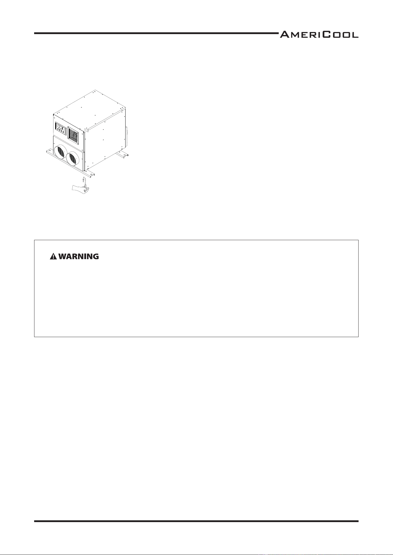
A er unpacking the unit, carefully inspect unit for any damage that may have occurred during
transit. Check for any loose, missing or damaged parts.
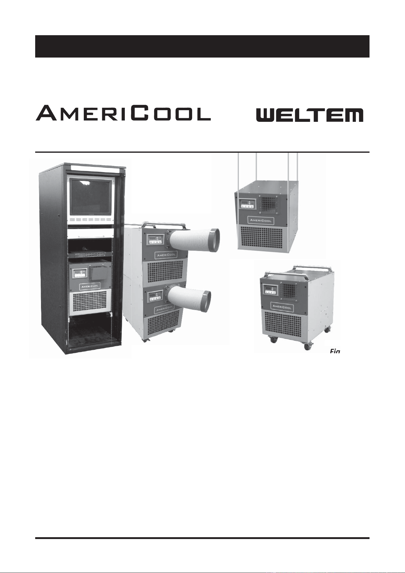
DescripƟ on
Unpacking
WMC-2500
Figure 1
Owner’s Manual
WMC-2500
Modular Multi Air Conditioner
by
W
M
C
Fi
g

2
Owner’s Manual
WMC-2500
Table of Contents
SPECIFICATION...............................................................................................4
GENERAL SAFETY INFORMATION....................................................................4
APPLICATIONS................................................................................................6
Portable
Server Rack
Mounted, Hang
Stack
ASSEMBLY (STANDARD)..................................................................................7
Component Parts
Power Cord Holder
ASSEMBLY (PORTABLE)...................................................................................8
Component Parts
Handle
Cool air duct assembly
Caster
ASSEMBLY (SERVER RACK)..............................................................................9
Component Parts
Universal adjust
Rack Assembly
Rack Diff user
ASSEMBLY (MOUNTED, HANG).....................................................................10
Condenser Intake Air Duct Flange
Eva Intake Air Duct Flange
Hanging Kit
ASSEMBLY (STACK)........................................................................................12
Universal Adjust
Stacking Bracket
INSTALLATION GUIDE....................................................................................13
Moving the Unit
Plugging the Unit
OPERATION..................................................................................................14
Control Panel
MAINTENANCE.............................................................................................16
Filter Cleaning
WIRING DIAGRAM........................................................................................20
TROUBLESHOOTING.....................................................................................21
LIMITED WARRANTY.....................................................................................24

3
Owner’s Manual
WMC-2500
* The WMC-2500 is used in conjunc on with various accessories to adapt to your envi-
ronmental needs. These accessories (Portable Kit, Server Rack Kit, Hanging Kit, Stack Kit)
are sold separately to allow you to customize the WMC-2500 to your specifi c needs
Shipping list
Modular air condi oner 1 unit
Owner’s Manual 1 pcs
Power Cord Holder 1 pcs
Drain hose (20 length) 1 pcs
Thank you for selec ng this AmeriCool by Weltem Modular Air Condi oner. It provides
you with spot cooling for large areas where cooling of an en re area is not prac cal or
possible. Please read this manual before installing the WMC-2500 as it provides impor-
tant informa on that should be followed during installa on and maintenance of the
Portable Air Condi oner, allowing you to correctly set up your system for the maximum
safety and performance. Included is informa on on customer support and service, if it is
required. If you experience a problem with the unit, please refer to the Troubleshoo ng
sec on in this manual to correct the problem. If the problem is not corrected, please
collect informa on so that the Technical Support personnel can more eff ec vely assist
you.
4
Owner’s Manual
WMC-2500
Model No. Power Supply Ph-V-Hz
Cooling Capac-
ity Btu/h
Power Consump-
on Wa s
Rated Cur-
rent Amps
EER Btu/
Wh
WMC-2500 Single Phase, 115V, 60Hz 10,000 1000 10 10.0
Model No. Nema Plug
Power Cord
Gauge AWG
Power Cord Length
Dimensions
W x D x H - in. (mm)
WMC-2500 5-15P 14 10
17.25 x 24 x 20
(438 x 610 x 508)
Model No. Weight (Net / Gross) Lbs(kg)
No. of Cool Air
Outlets Pcs
Condensate tank
Gallons(Liters)
Ambient temperature
range °F( °C)
WMC-2500 121 / 128 (54 / 58) 1
Auto Pump
Included
64~113 (18~45)
Model No.
Se ng temperature
(Room cool mode) °F( °C)
Se ng temperature
(Spot cool mode) °F( °C)
WMC-2500 64~86 (18~30) 32~86 (0~30)
Model No.
Applica on Area
(Room cool mode) ²(m²)
Refrigerant
Type / oz(g)
Design Pressure - Hi/
Low Psig
WMC-2500 258 (24) 16 (440) 465 / 250
Model No.
Indoor Air Flow
(High/Low)CFM(CMM)
Wheels
pcs / diameter
Hot Air Duct Diam-
eter In.(mm)
Maximum Duct Length
(m)
WMC-2500 320 / 220 (9.1 / 6.2) 4 / 76.2mm 6 (150) 10 (3)
Safety Devices
Compressor overload protector, An -freezing thermister,
Automa c restart (Power interrup on), Compressor me
delay program, High pressure switch
Features
Temperature control, Self-diagnos c func on, Two speed
fan, Washable fi lters, °F( °C) display, Off - mer, Drain pump
is included, Humiaity control.
General Safety InformaƟ on
Please read this manual carefully for instruc ons on correct installa on and usage. Please read
all safeguards,
1. Transport and store the unit in and upright posi on only. Leave unit in an upright posi on for
at least 3 hours before fi rst use.
2. Always place the unit on an even, level surface.
3. Ensure the unit is connected to a grounded power supply of the correct ra ng / capacity.
4. The unit will cool when the room temperature is between 18˚C (64.4˚F) ~ 45˚C (113˚F) de-
pending on the thermostat se ng.
5. DO NOT use this unit for func ons other than those described in this instruc on manual.
6. DO NOT lt the unit.
Specifi caƟ ons
5
Owner’s Manual
WMC-2500
7. DO NOT cover or obstruct the unit’s inlet and outlet grilles.
8. DO NOT use the unit in areas where it will be exposed to rain or water.
9. NEVER unplug the while it is opera ng.
DO NOT use the unit in wet environments, such as a laundry room, to avoid
the risk of electrical shock.
DO NOT operated the unit in explosive or fl ammable environments.
DO NOT operate a unit with a damaged power cord.
10. DO NOT place any foreign objects on the unit.
11. DO NOT operate the unit with wet or damp hands.
12. DO NOT allow chemical substances to come into contact with the unit.
13. DO NOT operate the unit in the presence of fl ammable substances or vapors such as alcohols,
pes cides, gasoline, etc.
14. DO NOT use the plug to start and to stop the unit. Always use the control panel to start and
to stop the unit.
15. Always turn off the unit when it is not in use and unplug the power plug from the electrical
outlet.
16. Always turn the unit off and unplug the main power plug from the electrical outlet before
cleaning, moving or performing maintenance,
17. AVOID the use of adapter plugs or extension cords. If it is necessary to use an extension cord
or an adapter plug to operate the unit, ensure that they are correctly rated for the applica-
on. Consult a local qualifi ed electrician and all local electrical codes to ensure proper setup.
Any extension cord used with this device must be rated for a minimum of 15A.
18. DO NOT unplug the unit by pulling on the electrical cord. Keep electrical cord away from heat
sources and always completely unroll the cord to avoid overhea ng. If the power cord be-
comes damaged, a qualifi ed service agent, qualifi ed electrician, or similarly qualifi ed person
must replace it, in order to avoid a hazard or shock.
19. The fi lters must be used with the product at all mes. When the fi lters are removed for clean-
ing, always ensure that the unit has been turned off and unplugged from the electrical outlet.
20. Regularly clean the fi lters to maintain effi ciency. If the fi lters are not cleaned regularly, the unit
output performance and effi ciency will decline and energy consump on will increase.
21. DO NOT operate the unit with a damaged power cord or plug, a er it malfunc ons, has been
dropped or damaged.
22. Only use in the upright posi on on an even, fl at surface. Unit must be posi oned at least 24
inches (60cm) from the nearest object in any direc on.
23. Stop opera on immediately if abnormal noise or odor is no ced. Contact a local service center.
24. Appliance is not used by children or persons with reduced physical, sensory or mental capabili-
es, or lack of experience and knowledge, unless they have been given supervision or instruc-
on.
25. Children being supervised not to play with appliance.
26. That the appliance shall be installed in accordance with na onal wiring regula ons.
27. If the supply cord is damaged, it must be replaced by the manufacturer, its service agent or
similarly qualifi ed persons in order to avoid a hazard.
SAVE THESE INSTRUCTIONS.

6
Owner’s Manual
WMC-2500
ApplicaƟ ons
With various accessories, Modular mul air condi oner provides best applica on to suit cus-
tomer’s individual needs.
PORTABLE
- This unit has ability to move easily from room to room using portable kit. It is available spot
cooling for large areas where cooling of the en re area in not prac cal. This air condi oner can
also be used in smaller areas for room cooling.
Portable kit includes casters, cool air duct assy and handle.
SERVER RACK
- It can be rack-mounted inside 19" computer server rack for cooling small computer and server
rooms. This unit occupies just 12U of valuable rack space.
Server Rack kit includes server rack assy (shelf), universal adjust (mount feet) and rack diff user.
MOUNTED, HANG
- It can be used to mounted type where your needs and hung type using ceiling mounted kit.
Hanging kit includes a eva intake air fl ange, a condenser fi lter/ intake air fl ange and hanging kit
(support).
All hanging installa ons must be completed by a qualifi ed electrical technician to permanently
connect the unit to a fi xed loca on (hardwared).
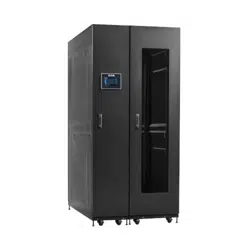
STACK
- This unit can be stacked on top of each other to produce a capacity of 20,000BTU or 30,000 BTU
in same area. It allows you to stack WMC-2500 up to 3 high. You can enjoy space effi ciency and
bigger cooling capacity.
Stack kit includes universal adjust (mount feet) and stacking bracket.
7
Owner’s Manual
WMC-2500
ASSEMBLY (Standard)
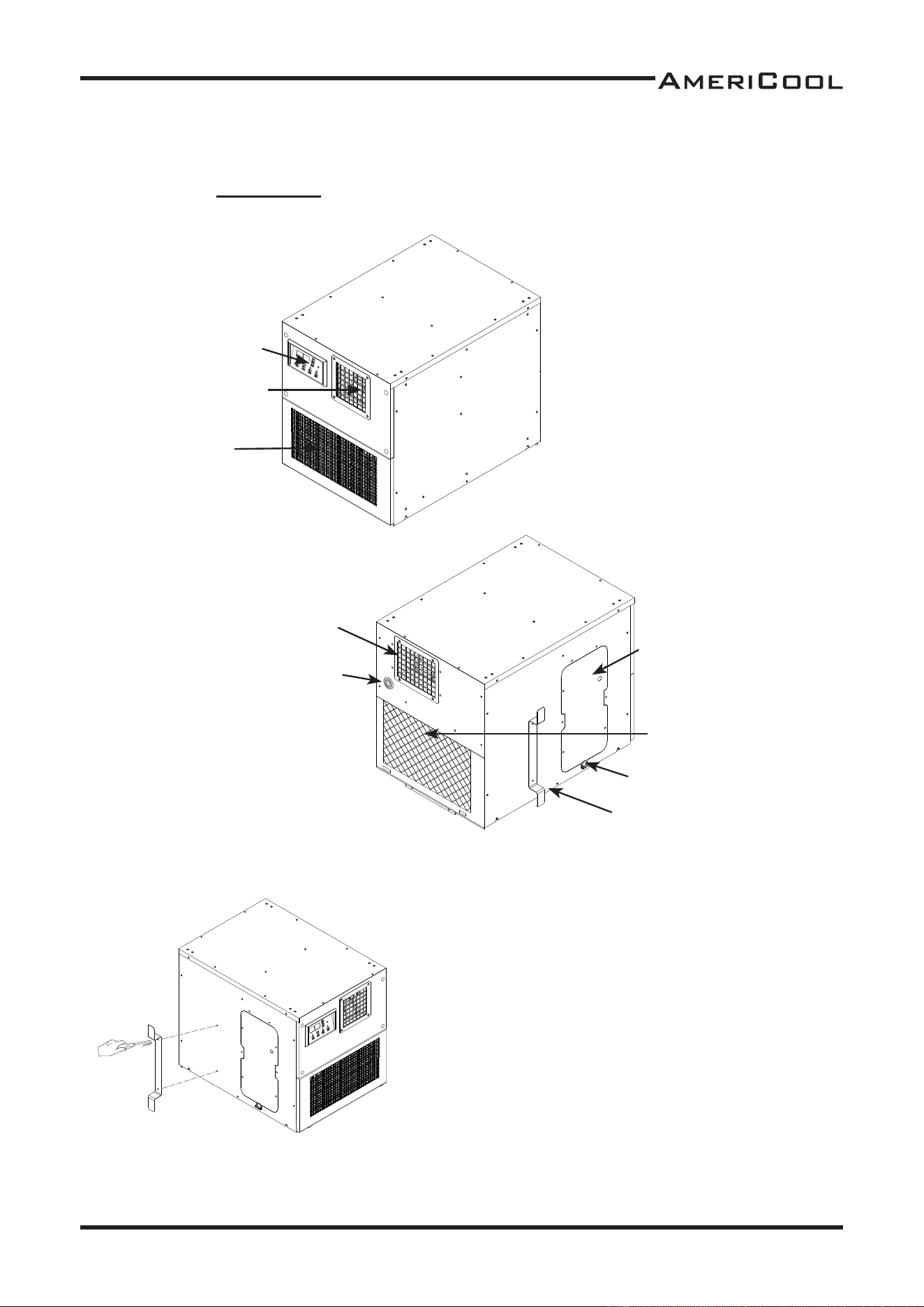
COMPONENT PARTS
POWER CORD HOLDER
1. Take out the cord holder from the accessory box.
2. Place the cord holder on the le side of unit.
3. Use screws (enclosed inside of accessory box with
cord holder) to install the cord holder in the unit as
shown in Figure 4.
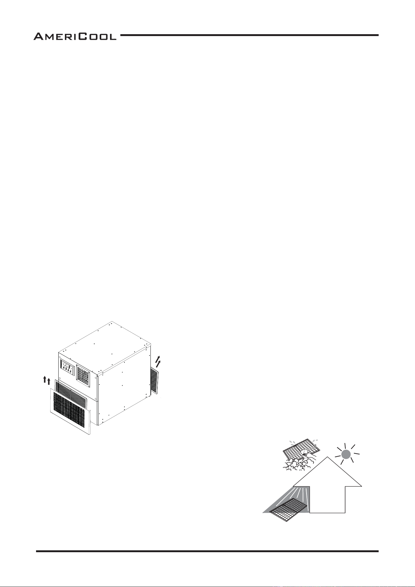
Display /Control Panel
Cool Air Outlet
Evaporator / Filter
Condenser / Filter
Power cord Holder
Power cord
Electrical Access
Panel
Drain Pump Hose
Connector
Exhaust Air Outlet
Figure 2 - front and
Right Side View
Figure 3 - rear and
Le Side View
Figure 4 - power cord
holder a achment
8
Owner’s Manual
WMC-2500
Figure 7 - cool air duct
assy a achment
Figure 8 -
caster a achment
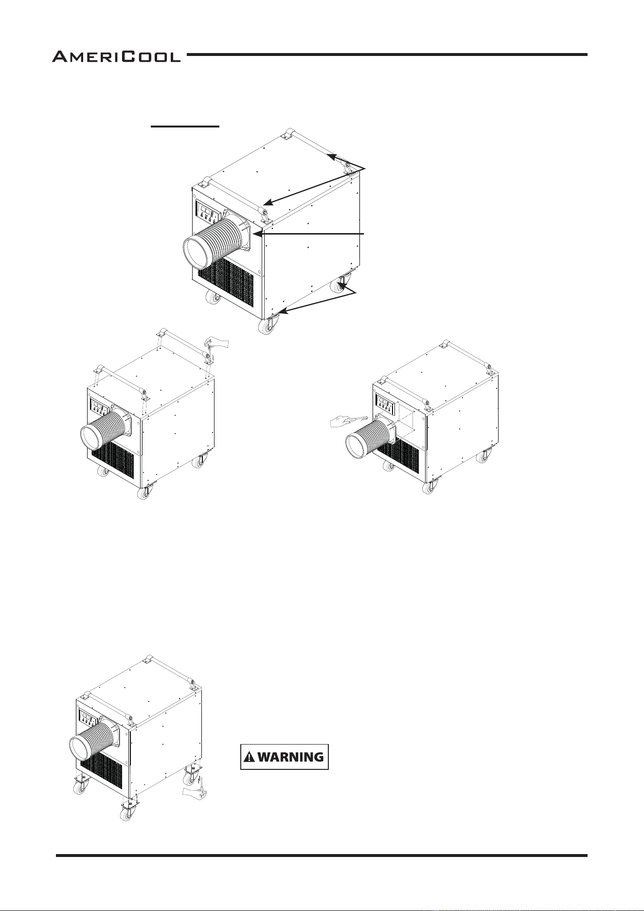
COOL AIR DUCT ASSEMBLY
CASTER
HANDLE
1. Remove cool air duct assembly 1 pcs from
carton.
2. Replace air cover with air duct assembly on
the top front of unit.
3. Use screws (enclosed inside of box with cool
air duct assembly) on the unit as shown in
Figure 7.
1. Take out the caster 4 pcs from the accessory box.
2. Place the casters on the base panel of unit.
3. Use screws (enclosed inside of accessory box with
caster) to install in the unit as shown in Figure 8.
The unit is upright posi on only. Leave unit in an up-
right posi on for at least 3 hours before fi rst use.
1. Take out the handle 2 pcs from the acces-
sory box.
2. Place the handle on the top of unit.
3. Use screws (enclosed inside of accessory
box with handle) to install the cord holder
on the unit as shown in Figure 6.
Figure 6 - handle
a achment
DO NOT lt the unit on it’s side.
ASSEMBLY (Portable)
COMPONENT PARTS
Figure 5 - portable kit a achment
Cool air duct
Caster
Handle
9
Owner’s Manual
WMC-2500
Figure 9 - server rack kit
a achment
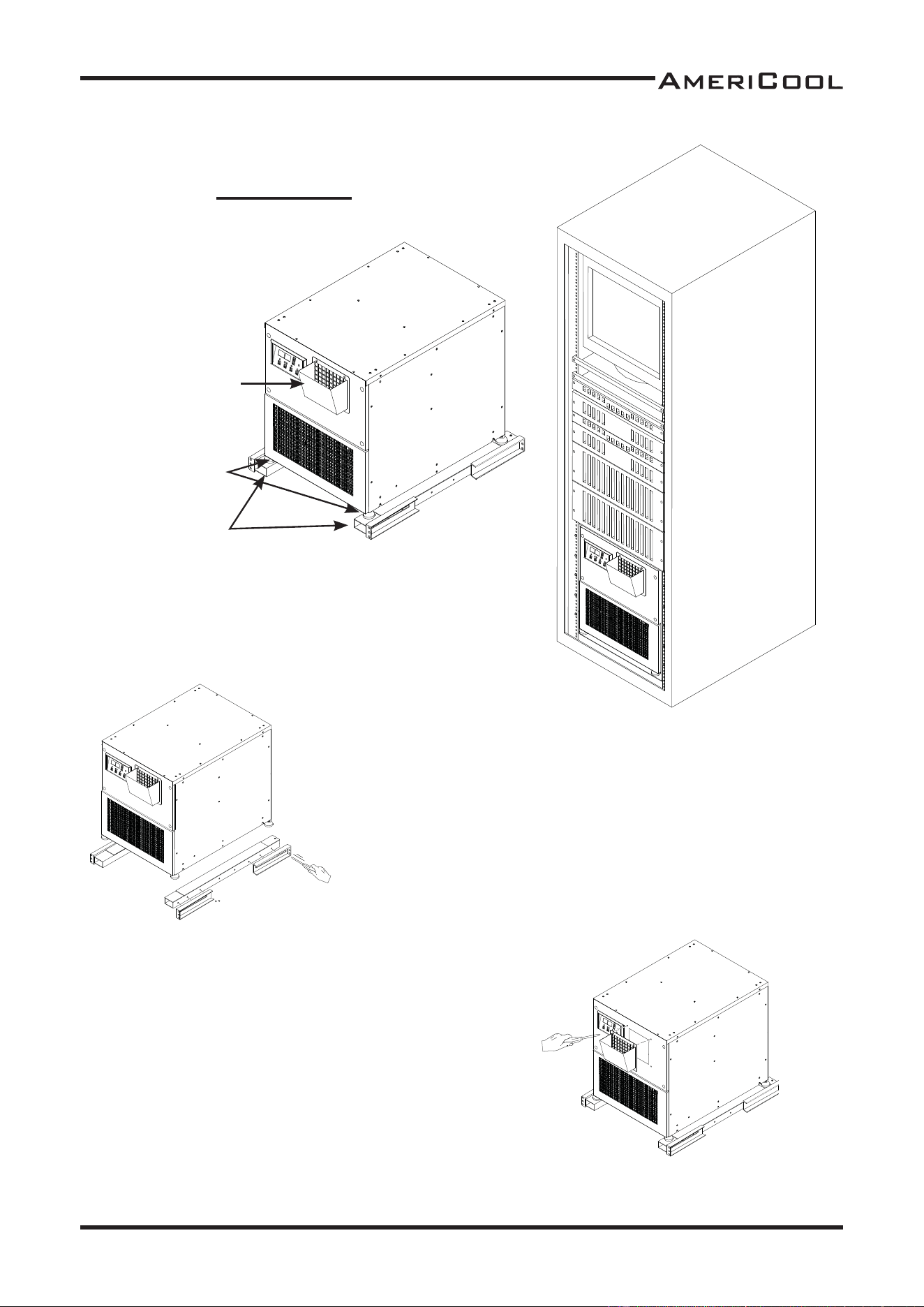
ASSEMBLY (Server Rack)
COMPONENT PARTS
Rack diff user
* See Figure 19 on page 12.
Universal adjust
Rack assembly
Figure 10 - installa on
in 19” server rack
Figure 11- rack assembly
a achment
1. Assemble the rack assembly parts 1set (6ea) to
fi t in server rack.
2. Use screws to install the rack assembly in server
rack as shown in Figure 11.
3. Place the unit on the rack assembly.
RACK ASSEMBLY
Figure 12 - rack diff user
a achment
1. Remove rack diff user 1 pcs from carton.
2. Replace air cover with rack diff user on the top
front of unit.
3. Use screws (enclosed inside of box with rack dif-
fuser) on the unit as shown in Figure 12.
RACK DIFFUSER
10
Owner’s Manual
WMC-2500
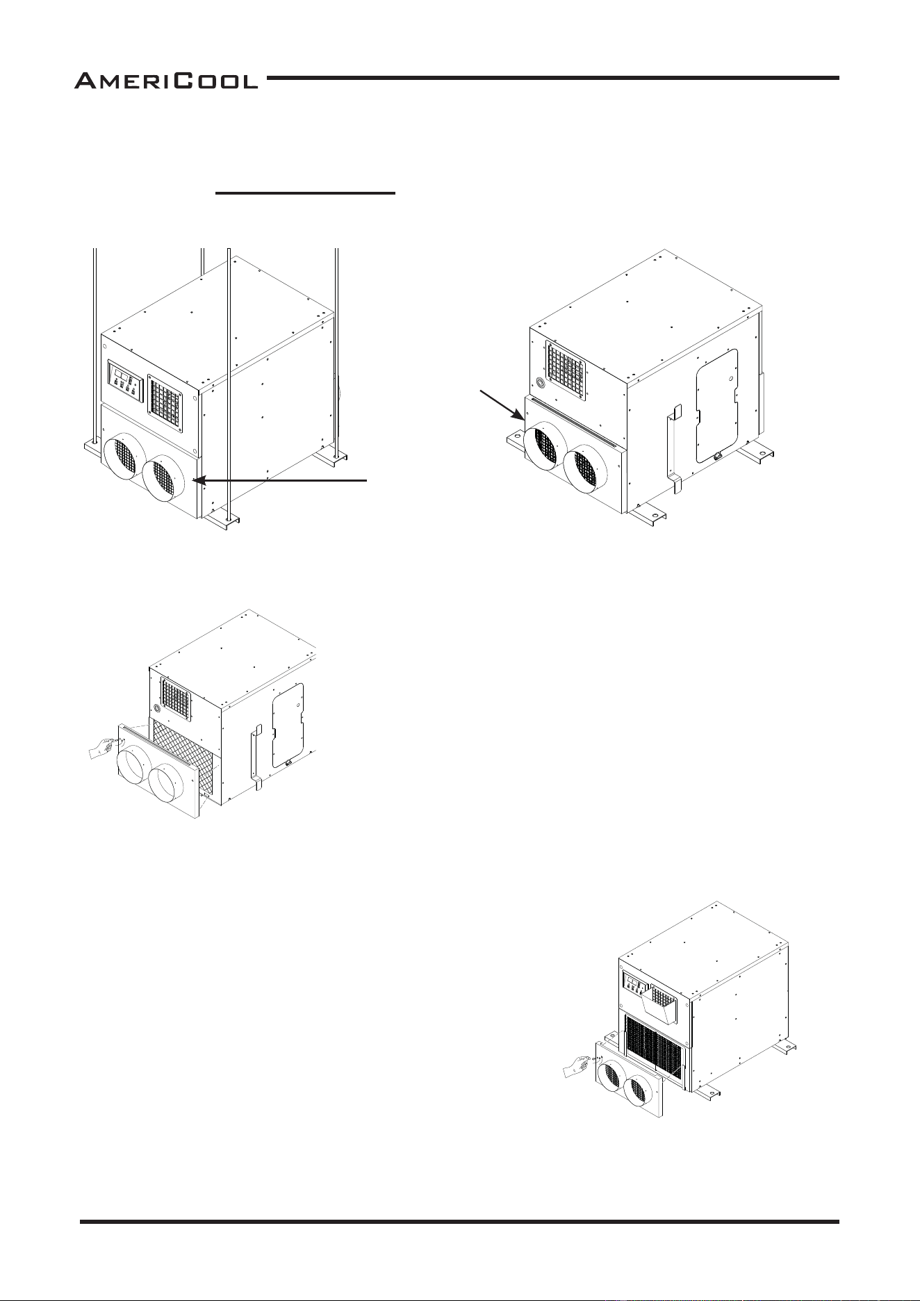
Figure 14 - Rear and
Le Side View
Figure 13 - Front and
Right Side View
Figure 15 - condenser
fl ange a achment
Figure 16 - eva fl ange
a achment
1. Remove condenser intake air duct fl ange (in-
cluded fi lter) 1 pcs from carton.
2. Take out condenser fi lter of unit and U Panel of
rear bo om.
3. Place the condenser fl ange on the rear of air
condi oner.
4. Use screw (enclosed inside of box with condenser
fl ange) to install the fl ange as shown in Figure 15.
1. Remove Eva intake air duct fl ange 1 pcs from
carton.
2. Slide up fi lter on the front of the unit and take out
front grill.
3. Put the fi lter in the eva fl ange and place the air
duct on the front of air condi oner.
4. Use screw (enclosed inside of box with air duct
fl ange) to install the fl ange as shown in Figure 16.
ASSEMBLY (Mounted, Hang)
COMPONENT PARTS
CONDENSER INTAKE AIR DUCT FLANGE
Condenser intake
air outlet
EVA INTAKE AIR DUCT FLANGE
Eva intake
air outlet
11
Owner’s Manual
WMC-2500
Figure 17 - hanging assem-
bly a achment
1. Install 1/2” threaded rod and vibra on insulator to
ceiling.
2. Remove Hanging assembly 1 set (2ea) from carton.
3. Place the hanging assy horizontally on the base of air
condi oner.
4. Use screw (enclosed inside of box with hanging kit) to
install as shown in Figure 17.
5. Li and mounted the unit.
Removing the power supply cord and permanently connec on the unit should be per-
formed only by a qualifi ed electrician.
WMC-2500 is heavy.(121lbs) A minimum of 2 people are required to li the unit.
When hanging and permanently connec ng the unit all applicable local/state/federal
building codes must be followed.
The structural beam being used must be properly support the weight of WMC-2500.
HANGING ASSEMBLY
12
Owner’s Manual
WMC-2500
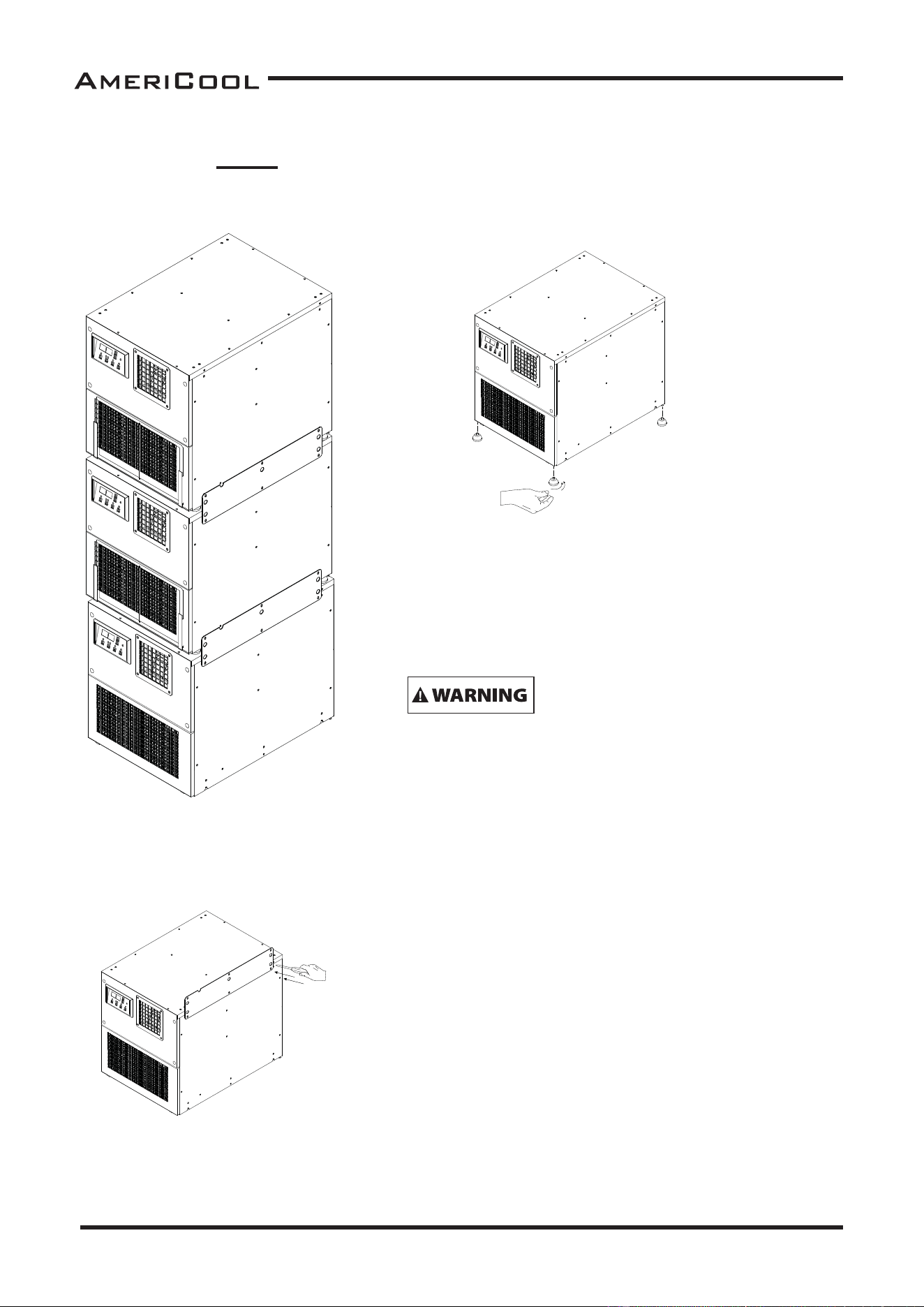
ASSEMBLY (Stack)
COMPONENT PARTS
UNIVERSAL ADJUST
STACKING BRACKET
Figure 18 - 3 unit
stacked applica on.
Figure 19 - universal
adjust a achment
Figure 20 - braket
a achment
1. Take out the universal adjust 4 pcs from the acces-
sory box.
2. Place the universal adjust on the base panel of unit.
3. Install on the unit as shown in Figure 19.
The unit is upright posi on only. Leave unit in an up-
right posi on for at least 3 hours before fi rst use.
1. Take out the stacking bracket 1 pcs from the accessory
box.
2. Place the stacking bracket on the right side panel of unit.
3. Use screw (enclosed inside of box with bracket) to install
as shown in Figure 20.
4. Stack the Unit.
5. Use screw (enclosed inside of box with bracket) to install
as shown in Figure 20.
DO NOT lt the unit on it’s side.
13
Owner’s Manual
WMC-2500
InstallaƟ on Guide
MOVING THE UNIT
Please li and carry more than 2 people. If casters are set to the unit, unlock the casters and
push the unit to a fl at, level surface and set the caster brakes to the locked posi on.
PLUGGINGING THE UNIT
Check the prongs and surface of the power cord plug for dust/dirt. If dust and/or dirt are pres-
ent, wipe off with a clean, dry cloth.
Check the power cord, plug and prongs for damage or excess play.
If any damage or excess play is found, contact a qualifi ed repair technician or a qualifi ed electri-
cian to perform replacement or repair of the power cord, plug or prongs.
NOTE : Make sure the AC outlet is free of dirt, oil, water or any other foreign material.
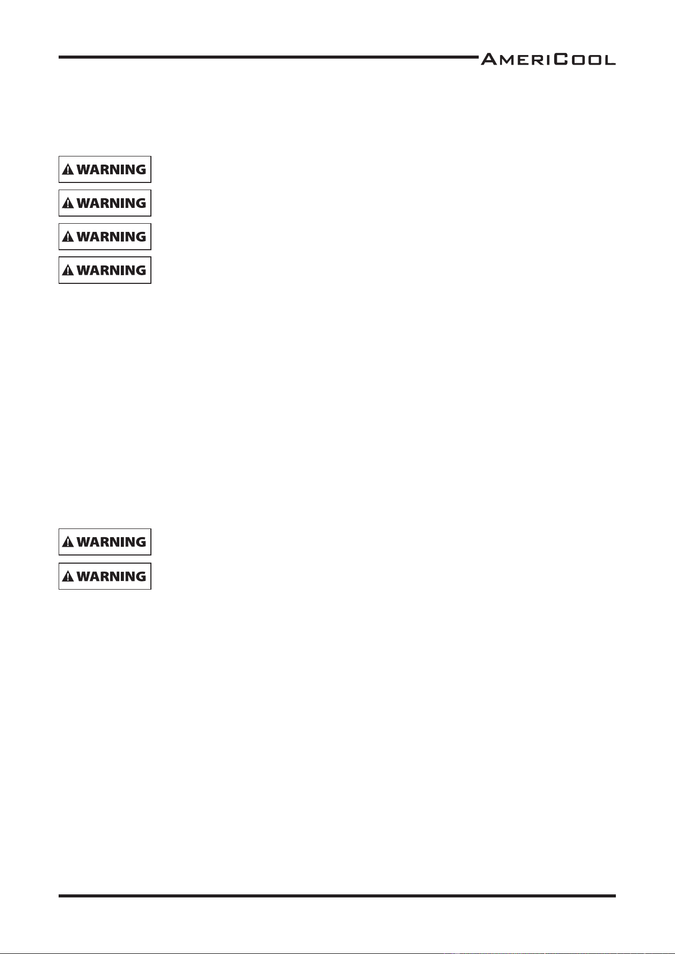
WARNING REGARDING PROPER LOCATION FOR INSTALLATION
Do not use the unit in explosive environments or in areas where fl ammable
gas leakage may occur.
Do not use the unit in a corrosive atmosphere.
Do not use the unit above 18˚C(64.4˚F)~45˚C(113˚F)
Do not install the unit on uneven or sloping surface. The unit may roll or
topple over even if the casters are set to the locked posi on.
If the power cord or plug is damaged, repair should only be performed by
qualifi ed electrical personnel.
Do not connect/ disconnect the power cord or a empt to operate bu ons
with wet hands. This could result in electrical shock.
14
Owner’s Manual
WMC-2500
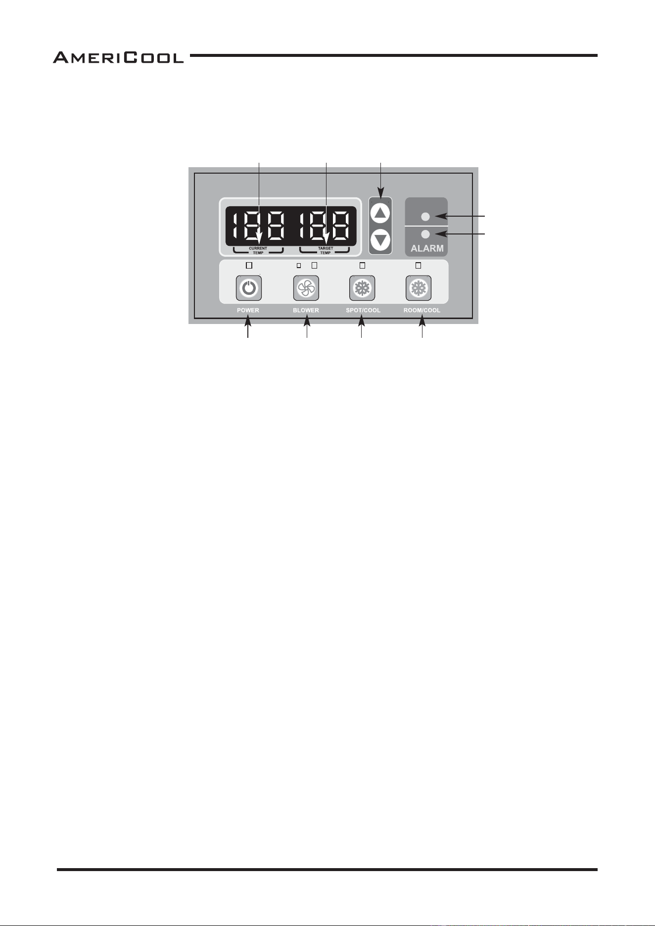
OperaƟ on
CONTROL PANEL
1. POWER BUTTON
Ac vates unit when POWER BUTTON is pressed. (Fan stats on low speed.)
If power bu on is pressed during opera on, unit stops.
2. BLOWER BUTTON
Changes fan speed [LOW]-[HIGH]-[AUTO] when pressed.
[LOW]-Small LED blinking
[HIGH]-Large LED blinking
[AUTO]-Both Small and Large LED blingking
* AUTO : AUTO mode will change the fan speed automa cally by diff erence of current temp. and
target temp.
When the current temp. is 7˚C/7˚F above the target temp, the unit will operate in HIGH Speed.
When the current temp. is 7˚C/7˚F under the target temp, the unit will operate in LOW Speed.
Changing me delay is 25 seconds.
(Time delay is applied to spot cool mode and room cool mode.)
3. SPOT/COOL BUTTON
Ac vates compressor and begins producing cool air 5 seconds a er bu on is pressed.
Regulates temperature based on outlet cool air temperature.
4. ROOM/COOL BUTTON
Ac vates compressor and begins producing cool air 5 seconds a er bu on is pressed.
Regulates temperature based on inlet ambient air temperature.
5. CURRENT TEMP
Displays current room temperature is display in Fahrenheit. (In Room Cool Mode only)
SPOT/COOL Mode – Displays outlet (cool air) temperature during normal opera ons.
In order to change ˚F to ˚C, press UP/DOWN bu on together for 1 second, and select tC mode by
press ROOM/COOL bu on.
“0” means ˚C, 1 means ˚F.
A er 5 seconds or press SPOT/BUTTON, the fi gure will be memorized.
1 2
7
3 4
9
8
65
DEHUMID.
Figure 21 - Display/Control Panel

15
Owner’s Manual
WMC-2500
6. TARGET TEMP
Displays the unit set temperature for ROOM/COOL mode only.
7. SET TEMP BUTTONS
Change target temperature/data value by +/-1. Change data value by +/- 10 by pressing con nu-
ally.
Press the SET TEMP BUTTONS to set temperature.
Upper bu on is to higher temperature and Low bu on is to lower temperature.
8. DEHUMIDIFICATION MODE.
Enter to Dehumidifi ca on Mode if you press SPOT/COOL bu on and ROOM/COOL bu on to-
gether for 1 second.
In Dehumidifi ca on mode, it will blink DEHUMID. Indicator LED,
If you want to use air condi oner, press SPOT/COOL bu on and ROOM/COOL bu on together for
1 second again.
9. ALARM
Alarm indicator lights (blinks) and indicates abnormal system opera on. If Alarm occurs,
compressor stops. System opera on stops when ALARM light is ac vated (blinks) longer than 3
minutes.
*DATA INITIALIZATION
It will be ini aliza on when you pressed “BLOWER+SPOT+ROOM” together more than 5 seconds.
If you pressed bu on together, you can see “in it” and blinking 2 seconds.
Then reset your target temperature.
*OFF-TIMER
The TIMER control turns off within a 12-hour period.
Enter to Timer Se ng Mode if you press BLOWER bu on and SPOT/COOL bu on together for 1
second.
Press UP/DOWN bu on to set the mer un l it shows the fi gure you want to set. (Se ng is avail-
able per 30 minutes)
A er 5 seconds or press SPOT/BUTTON, the fi gure will be memorized and compressor will stop
a er the me set.
OFF Timer is hold un l me up even though the unit restarts by power failure etc.
*AUTO RESTART
If the unit goes off due to an electrical interrup on, the unit will automa cally restart when the
power resumes.
16
Owner’s Manual
WMC-2500
Figure 22 – Removing Filters
Figure 23 – Removal of dust
Maintenance
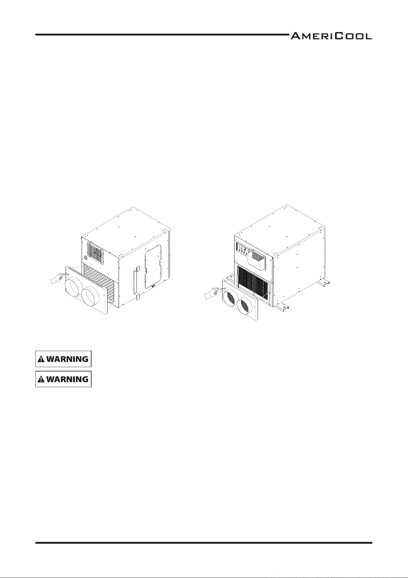
FILTER CLEANING (Without fl ange)
There are 2 fi lters in the unit. The evaporator fi lter is located at the front of the unit. The con-
denser fi lter is located at the rear of the unit.
1. Open the front grill.
2. Slide fi lter up and use vacuum cleaner to remove the dust from the fi lter.
3. If the fi lter is heavily covered with dust and dirt, warm water and mild soap or neutral deter-
gent may be used to wash the fi lter. Do not use any other chemicals to clean fi lter, as they will
likely damage the fi lter.
4. Dry the fi lter in a shaded area before replacing it. Do not operate the unit without the fi lter
installed and the fi lter frill in the closed posi on.
5. Replace the clean fi lter and close the fi lter grill.
6. To clean the condenser fi lter, li up on the rear fi lter from the middle bar slightly and then
angle the fi lter outwards from the bo om and remove.
7. Use the sale cleaning procedure as above (3~5)
8. To replace the condenser fi lter, place the top of the fi lter in the guide and slide the fi lter up
un l the bo om of the fi lter clears the frame.
Then push the bo om of fi lter into the guide and let fi lter into guide and let fi lter fall inside the
guide.
NOTE : For eff ec ve cooling clean the fi lter at least every 2 weeks.
– Remove dust from the fi lter using a vacuum
cleaner hose a achment.
– If required wash the fi lter in lukewarm water
with a mild detergent. Leave to dry in a shaded
area before reinstalling.
– Pull the fi lter frame forward to remove the front
fi lter.
– Slide fi lter up and use a vacuum cleaner to remove
the dust from the fi lter.
– Li up on the rear fi lter from the middle bar slightly
and then angle the fi lter outwards from the bo om
and remove.
17
Owner’s Manual
WMC-2500
FILTER CLEANING (With fl ange)
1. Loosen up 2 bolts on fl ange.
2. Slide fi lter up and use vacuum cleaner to remove the dust from the fi lter.
3. If the fi lter is heavily covered with dust and dirt, warm water and mild soap or neutral deter-
gent may be used to wash the fi lter. Do not use any other chemicals to clean fi lter, as they will
likely damage the fi lter.
4. Dry the fi lter in a shaded area before replacing it. Do not operate the unit without the fi lter
installed and the fi lter frill in the closed posi on.
5. Replace the clean fi lter and re-assembly fl ange on the unit..
NOTE : For eff ec ve cooling clean the fi lter at least every 2 weeks.
Figure 24 - Removing
condenser Filters
Figure 25 - Removing
evaporator Filters
- For your convenience, record the complete model number and product name (located on the
Product Iden fi ca on Plate), the purchase date, purchase loca on, serial number, and warranty
period in the table below.
- Also, a ach your purchase receipt as proof of purchase to this instruc on manual for future
reference.
- To ensure your product is covered by warranty, the complete faulty product along with you
original purchase receipt must be provided at the place of purchase.
Do not operate with out the fi lter fi ed.
Do not operate the unit with a damaged cord or plug, a er the unit malfunc-
ons or if the unit has been dropped or damaged.

18
Owner’s Manual
WMC-2500
Product Portable Air CondiƟ oner
Model No.
Date of Purchase
Place of Purchase
Serial No.
Period of Warranty
Customer: Please read and keep this
manual for future reference and keep
sales receipt as proof of purchase.
SELF-DIAGNOSTIC CODES (See Table 1)
The alarm light is ac vated if abnormal opera on occurs, and a code is displayed on the control
panel. The compressor and condenser fan motor will stop opera ng. The evaporator fan will con-
nue to run for 3 minutes. If the fault is rec fi ed within 3 minutes, the unit will resume opera-
on. If the fault persists for more than 3 minutes, the evaporator fan also stops. The fault must
be rec fi ed before the unit can resume normal opera on.
19
Owner’s Manual
WMC-2500
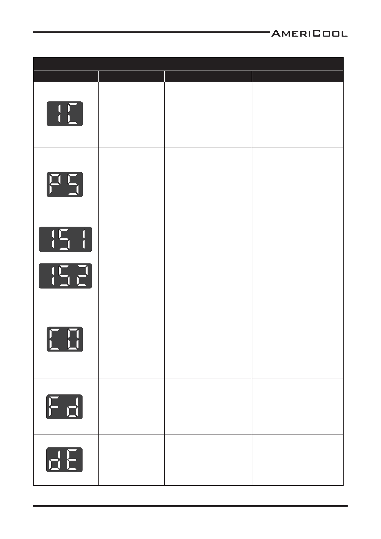
SELF-DIAGNOSTIC ALARM CODES
Alarm Display Problem Cause Correc ve Ac on
Frost preven on
sensor and
Abnormal
temperature
sensor value
• Indoor heat exchanger
temperature too low
• TH3 temperature
sensor has a loose or
broken connec on
• Do not use the air
condi oner if ambient
temperature is lower
than 18°C (64°F)
• Contact a qualifi ed
service agent
Refrigerant high
pressure switch
• Blocked air fi lter
• Blocked / kinked ex-
haust duct
• Ambient temperature
is too high
• Clean air fi lter
• Ensure exhaust duct is
not blocked / kinked
• Do not use the air
condi oner if ambient
temperature is higher
than 45°C (113°F)
Abnormal
temperature
sensor value
TH1(Outlet) temperature
sensor has a loose or
broken connec on
Contact a qualifi ed service
agent
Abnormal tem-
perature sensor
value
TH2(Inlet) temperature
sensor has a loose or
broken connec on
Contact a qualifi ed service
agent
Compressor over-
loaded
• Ambient temperature
is too high
• Unstable voltage
supply
• Defec ve compressor
• Over current relay
defect or broken
connec on
• Do not use the air
condi oner if ambient
temperature is higher
than 45°C (113°F)
• Contact a qualifi ed
service agent
• Replace compressor
Drain pump alarm
Drain pump defec ve
or improper hose
connec on (including
kink or blockage)
• Contact a qualifi ed
service agent
• Check the hose connec-
on and hose
• Replace drain pump
Abnormal
dehumidifi ca
on
sensor value
TH4(Dehumidifi ca on)
sensor has a loose or
broken connec on
Contact a qualifi ed service
agent
Table 1- Alarm Codes
20
Owner’s Manual
WMC-2500
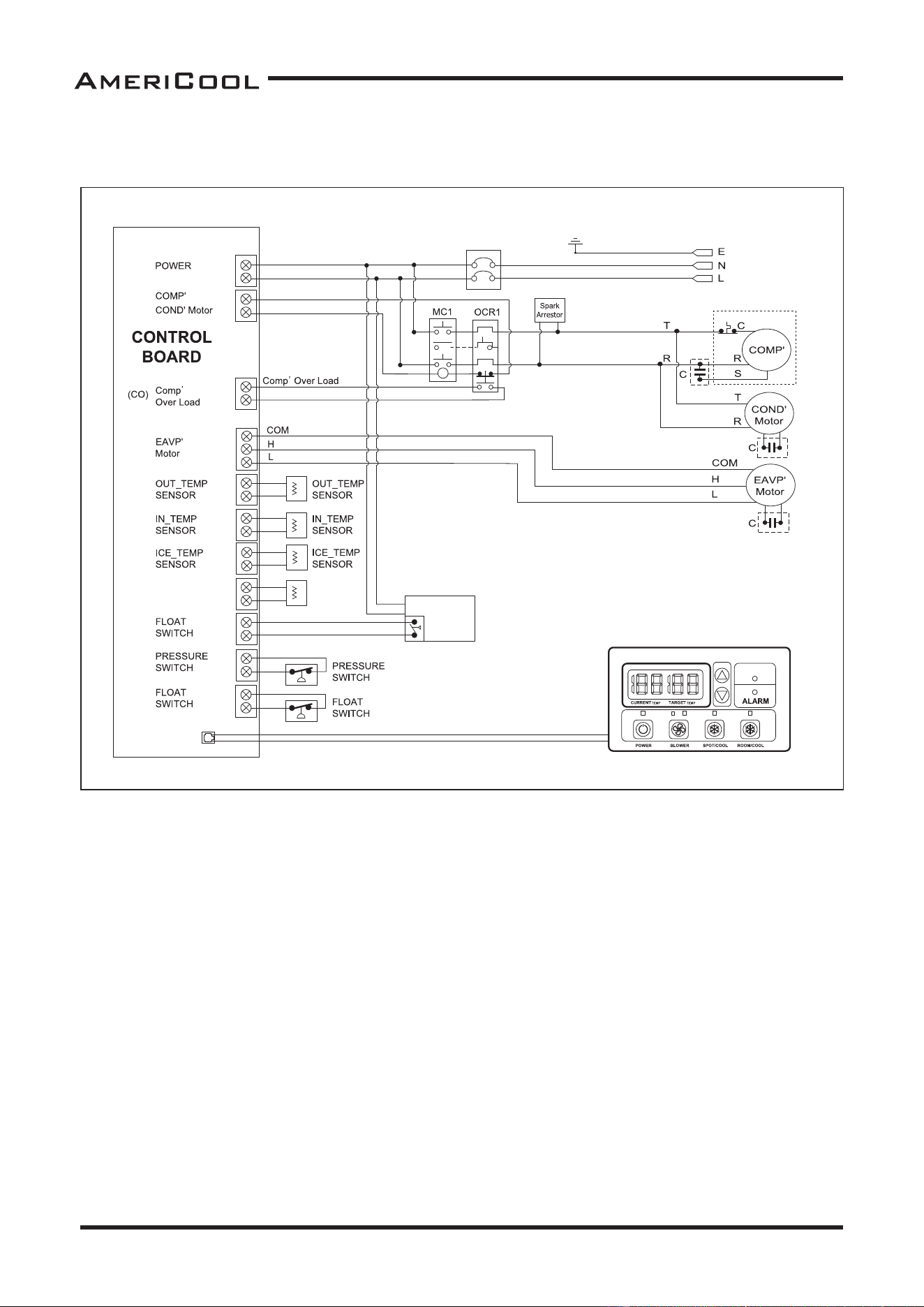
Wiring Diagram
Figure 26 - Circuit Wiring Diagram
(1S1)
(dE)
OUT_HUMIDITY
SENSOR
OUT_HUMIDITY
SENSOR
(1S2)
(IC)
(Fd)
(PS)
(FT)
DATA
CABLE
POWER
1P AC 115
1P AC 208 / 230V
DRAIN
PUMP
(option)
DEHUMID.

21
Owner’s Manual
WMC-2500
TroubleshooƟ ng chart
Symptom Possible Cause(s) Correc ve Ac on
The unit doesn’t work
1. Check the power supply
to verify that power is
available to the unit
1. Reset the circuit breaker and
restart the unit
2. Verify that the power
cord is connected
2. Connect power cord
No cold air fl ows from the
cold air outlet
1. Ambient air cannot be
properly cooled if the
fi lter is dirty and not
regularly cleaned
1. Clean the fi lter
2. Compressor will not
work if the unit is
turned off and on
quickly.
2. Wait 2 minutes a er unit is
turned off before turning the
unit back on.
3. The ambient air tem-
perature may be too
high
3. The temperature of the com-
pressor can be higher when
the ambient temperature is
too high. The compressor will
not work unless the ambient
air temperature is within the
acceptable opera ng range of
the unit
Water fl ow can be heard
a er compressor shuts off
No cause
Common to hear coolant fl owing
a er unit shuts off

22
Owner’s Manual
WMC-2500
OBTAINING SERVICE
If the AmeriCool by Weltem Modular Air CondiƟ oner requires Service:
1. Use the TROUBLESHOOTING sec on in this manual to eliminate obvious causes.
2. Verify there are no circuit breakers tripped.
3. Call your dealer for assistance. If you cannot reach your dealer, or if they cannot resolve the prob-
lem, call AmeriCool by Weltem Modular Air CondiƟ oner Technical Support at 562.231.7175.
Please have the following informa on available BEFORE calling the Technical Support Depart-
ment:
a. Your name and address.
b. The serial number of the unit.
c. Where and when the unit was purchased.
d. All of the model informa on about your AmeriCool by Weltem Modular Air CondiƟ oner.
e. Any informa on on the failure, including LED’s that may or may not be illuminated.
f. A descrip on of the protected equipment, including model numbers if possible.

23
PB
WMC-2500
Owner’s Manual
LIMITED WARRANTY
AmeriCool warrants all AmeriCool products to be free from defects in materials or workmanship,
under normal use and service, for a period of 12 months from the date of purchase to the end user
(original invoice must be provided). AmeriCool warrants that the compressor will be free from
defects in materials and workmanship for 12 months from the date of purchase to the end user.
AmeriCool’s obligaon under this warranty is limited to the repair or replacement at its opon,
of any part or parts, which, upon Ameriool’s examinaon are shown to be defecve, or at Ameri
-
Cool’s opon, the return of the purchase price to the purchaser.
Correcon
of such defects by repair or replacement, or at AmeriCool’s opon, the return of the
purchase price shall constute fulllment of warranty obligaons to the purchaser. This warranty
does not cover defects or malfuncons which result from causes beyond AmeriCool’s control,
including, without limitaon,(i) unusal physical or electrical stress:(ii) accident, neglect, abuse,
misuse or other abnormal use; (iii) failure to perform roune maintenance in accordance with
AmeriCool’s recommended procedures; (iv)normal wear and tear; (v) repairs or aempted repairs
by an unauthorized person; (vi) modicaons or alteraons to the Products; (vii) use with parts or
devices not supplied or approved by AmeriCool (viii) improper installaon or service; (ix) shipping
damage to any units or spare parts during shipping. This includes and is not limited to compres
-
sors, evaporators and condenser coils. This warranty shall extend only to the original end-user and
shall be
void if any labels or other idenfying marks permanently axed to Products when shipped
by AmeriCool are removed, altered, defaced or obliterated.
TO THE EXTENT PERMITTED BY LAW, THIS WARRANTY, AS LIMITED HEREIN, SHALL BE IN LIEU OF
AND EXCLUSIVE OF ALL OTHER WARRANTIES, EITHER EXPRESSED OR IMPLIED, ON THE PART OF
AMERICOOL INC., OR WELTEM CO.,LTD. WHETHER ARISING FROM LAW, COURSE OF DEALING, US
-
AGE OF TRADE, OR OTHERWISE, INCLUDING WITHOUT LIMITATION ANY IMPLIED WARRANTY OF
MERCHAN
T-ABILITY OR FITNESS OF A PARTICULAR PURP OSE OR ANY LIABILITY FOR COMMERCIAL
LOSSES BASED UPON NEGLIGENCE OR MANUFACTURER’S STRICT LIABILITY. EXCEPT AS EXPRESSLY
PROVIDED HEREIN,NEITHER AMERICOOL, INC., NOR WELTEM CO., LTD. WILL, IN ANY EVENT, BE
LIABLE FOR LOST PROFITS, COSTS OF PROCESSING,INJURY, GOODWILL, OR ANY OTHER CONSE
-
QUENTIAL DAMAGES OF ANY KIND ARISING FROM BREACH OF THIS WARRANTY.
Printed in January, 2021
Manufactured in Weltem Co., Ltd.,
154, Jayumuyeok 3-gil, Masanhoewon-gu, Changwon-City, Gyeongsangnam-do,
Republic of KOREA 51340 www.weltem.com
Distributed by Americool,Inc. In the USA (Tel.888-726-6158)
WWW.AMERICOOLLLC.COM