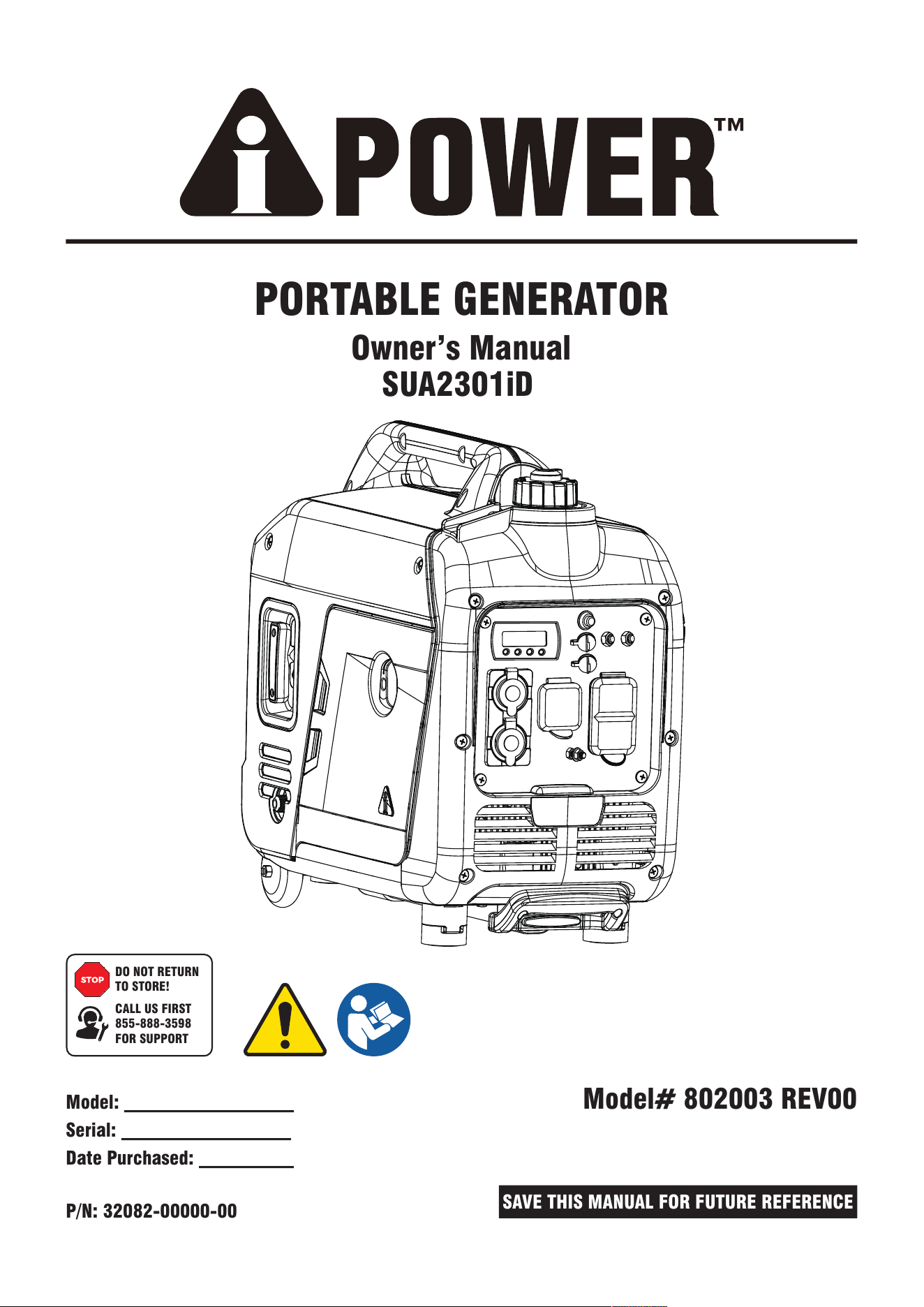
PORTABLE GENERATOR
Owner’s Manual
P/N: 32082-00000-00
Model:
Serial:
Date Purchased:
Model# 802003 REV00
SAVE THIS MANUAL FOR FUTURE REFERENCE
DO NOT RETURN
TO STORE!
CALL US FIRST
855-888-3598
FOR SUPPORT
SUA2301iD
Table of Contents
Introduction..........................................1
Safety....................................................1
General Safety Precautions....................2
Unpacking the Generator.......................8
Parts Included........................................8
Controls and Features............................9
Control Panel Features.........................11
Specifications......................................12
Add Engine Oil......................................15
CO WATCH-GUARD..............................13
Low Oil Shutdown................................15
Add Fuel: Gasoline................................15
FUEL SENSE........................................17
Add Fuel: Propane/LPG.........................16
Operation at High Altitude.....................18
Grounding............................................18
Connecting to a Building’s Electrical System...18
Operation............................................19
Generator Location...............................19
Surge Protection...................................19
Before Starting the Generator................19
Starting the Engine (Generator).............20
Select the Fuel Source (Gasoline)...........20
Select the Fuel Source (Propane/LPG)....20
Connecting Electrical Loads..................21
Low Idle Switch....................................21
Stopping the Engine..............................22
Low Oil Shutdown................................22
Do Not Overload Generator....................22
Changing Fuels.....................................23
Parallel Operation.................................24
Maintenance And Storage....................26
Maintenance Schedule.........................26
Engine Maintenance.............................26
Engine Oil Level Check.........................26
Change Engine Oil................................27
Air Filter Maintenance...........................28
Spark Plug Maintenance.......................28
Valve Clearance..................................28
Cleaning the Spark Arrestor.................29
Generator Maintenance.........................29
Storage................................................29
Draining the Float Bowl.........................30
Trouble Shooting..................................31
Parts Diagram and Parts List................32
Parts Diagram......................................32
Parts List.............................................33
Circuit Diagram....................................34
Warranty..............................................35
INTRODUCTION
SAFETY
Read This Manual Thoroughly
The manufacturer cannot possibly anticipate every possible circumstance that might involve a hazard. The
warnings in this manual and the tags and decals affixed to the unit are therefore not all-inclusive. If you use a
procedure, work method or operating technique that the manufacturer does not specifically recommend you
must satisfy yourself that it is safe for you and others. You must also make sure that the procedure work
method or operating technique that you choose does not render the generator unsafe.
If any section of this manual is not understood,
contact customer Service at 855-888-3598, or
www.a-ipower.com for starting, operating and
servicing procedures. The owner is responsible for
proper maintenance and safe use of the unit.
SAVE THESE INSTRUCTIONS for future reference.
This manual contains important instructions that
must be followed during placement, operation and
maintenance of the unit and its components. Always
supply this manual to any individual that will use this
unit.
The information in this manual is accurate based on
products produced at the time of publication. The
manufacturer reserves the right to make technical
updates, corrections and product revisions at any
time without notice.
Page 01
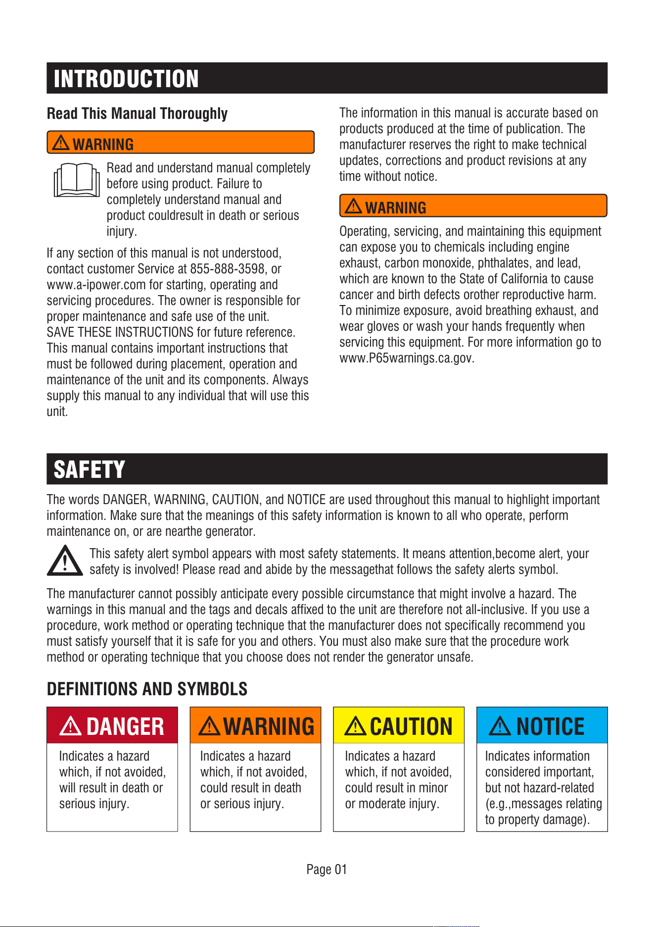
DEFINITIONS AND SYMBOLS
DANGER
Indicates a hazard
which, if not avoided,
will result in death or
serious injury.
WARNING
Indicates a hazard
which, if not avoided,
could result in death
or serious injury.
NOTICE
Indicates information
considered important,
but not hazard-related
(e.g.,messages relating
to property damage).
CAUTION
Indicates a hazard
which, if not avoided,
could result in minor
or moderate injury.
WARNING
Read and understand manual completely
before using product. Failure to
completely understand manual and
product couldresult in death or serious
injury.
WARNING
Operating, servicing, and maintaining this equipment
can expose you to chemicals including engine
exhaust, carbon monoxide, phthalates, and lead,
which are known to the State of California to cause
cancer and birth defects orother reproductive harm.
To minimize exposure, avoid breathing exhaust, and
wear gloves or wash your hands frequently when
servicing this equipment. For more information go to
www.P65warnings.ca.gov.
The words DANGER, WARNING, CAUTION, and NOTICE are used throughout this manual to highlight important
information. Make sure that the meanings of this safety information is known to all who operate, perform
maintenance on, or are nearthe generator.
This safety alert symbol appears with most safety statements. It means attention,become alert, your
safety is involved! Please read and abide by the messagethat follows the safety alerts symbol.
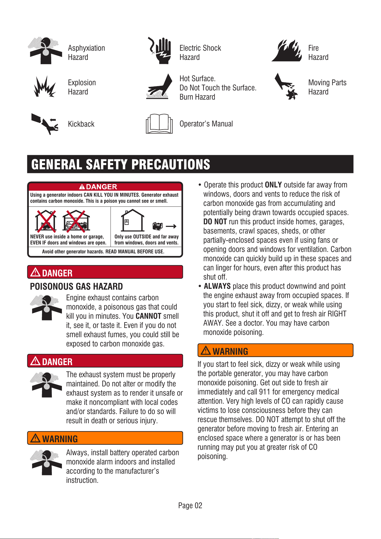
Engine exhaust contains carbon
monoxide, a poisonous gas that could
kill you in minutes. You CANNOT smell
it, see it, or taste it. Even if you do not
smell exhaust fumes, you could still be
exposed to carbon monoxide gas.
Asphyxiation
Hazard
Fire
Hazard
Hot Surface.
Do Not Touch the Surface.
Burn Hazard
Page 02
Kickback
Electric Shock
Hazard
Explosion
Hazard
Moving Parts
Hazard
Operator’s Manual
GENERAL SAFETY PRECAUTIONS
POISONOUS GAS HAZARD
DANGER
Using a generator indoors CAN KILL YOU IN MINUTES. Generator exhaust
contains carbon monoxide. This is a poison you cannot see or smell.
NEVER use inside a home or garage,
EVEN IF doors and windows are open.
Avoid other generator hazards. READ MANUAL BEFORE USE.
Only use OUTSIDE and far away
from windows, doors and vents.
The exhaust system must be properly
maintained. Do not alter or modify the
exhaust system as to render it unsafe or
make it noncompliant with local codes
and/or standards. Failure to do so will
result in death or serious injury.
DANGER
Always, install battery operated carbon
monoxide alarm indoors and installed
according to the manufacturer’s
instruction.
• Operate this product ONLY outside far away from
windows, doors and vents to reduce the risk of
carbon monoxide gas from accumulating and
potentially being drawn towards occupied spaces.
DO NOT run this product inside homes, garages,
basements, crawl spaces, sheds, or other
partially-enclosed spaces even if using fans or
opening doors and windows for ventilation. Carbon
monoxide can quickly build up in these spaces and
can linger for hours, even after this product has
shut off.
• ALWAYS place this product downwind and point
the engine exhaust away from occupied spaces. If
you start to feel sick, dizzy, or weak while using
this product, shut it off and get to fresh air RIGHT
AWAY. See a doctor. You may have carbon
monoxide poisoning.
WARNING
If you start to feel sick, dizzy or weak while using
the portable generator, you may have carbon
monoxide poisoning. Get out side to fresh air
immediately and call 911 for emergency medical
attention. Very high levels of CO can rapidly cause
victims to lose consciousness before they can
rescue themselves. DO NOT attempt to shut off the
generator before moving to fresh air. Entering an
enclosed space where a generator is or has been
running may put you at greater risk of CO
poisoning.
WARNING
Page 03
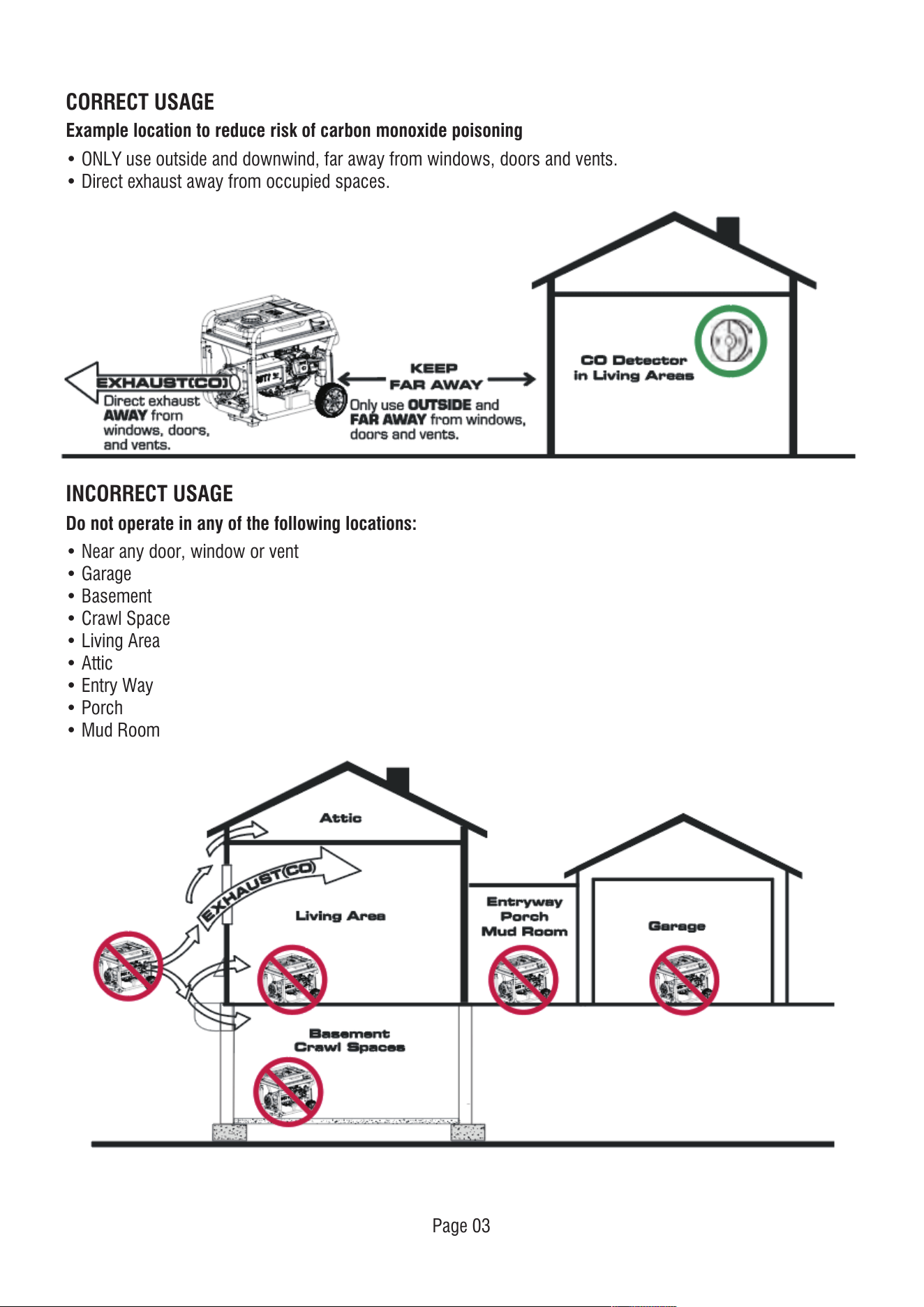
• ONLY use outside and downwind, far away from windows, doors and vents.
• Direct exhaust away from occupied spaces.
CORRECT USAGE
Example location to reduce risk of carbon monoxide poisoning
INCORRECT USAGE
• Near any door, window or vent
• Garage
• Basement
• Crawl Space
• Living Area
• Attic
• Entry Way
• Porch
• Mud Room
Do not operate in any of the following locations:
Page 04
FUEL SAFETY
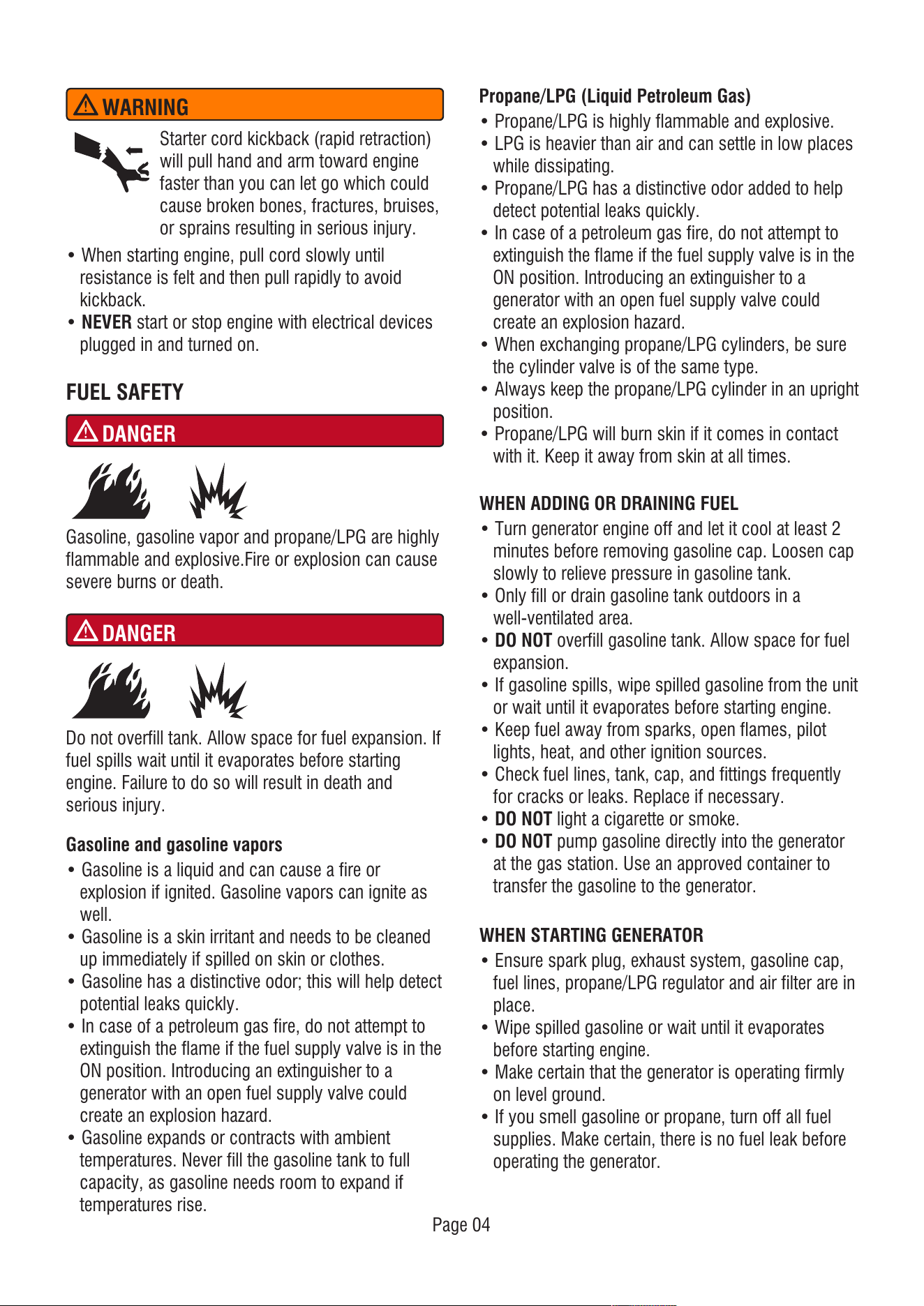
• When starting engine, pull cord slowly until
resistance is felt and then pull rapidly to avoid
kickback.
• NEVER start or stop engine with electrical devices
plugged in and turned on.
Starter cord kickback (rapid retraction)
will pull hand and arm toward engine
faster than you can let go which could
cause broken bones, fractures, bruises,
or sprains resulting in serious injury.
WARNING
DANGER
Gasoline and gasoline vapors
• Gasoline is a liquid and can cause a fire or
explosion if ignited. Gasoline vapors can ignite as
well.
• Gasoline is a skin irritant and needs to be cleaned
up immediately if spilled on skin or clothes.
• Gasoline has a distinctive odor; this will help detect
potential leaks quickly.
• In case of a petroleum gas fire, do not attempt to
extinguish the flame if the fuel supply valve is in the
ON position. Introducing an extinguisher to a
generator with an open fuel supply valve could
create an explosion hazard.
• Gasoline expands or contracts with ambient
temperatures. Never fill the gasoline tank to full
capacity, as gasoline needs room to expand if
temperatures rise.
Propane/LPG (Liquid Petroleum Gas)
• Propane/LPG is highly flammable and explosive.
• LPG is heavier than air and can settle in low places
while dissipating.
• Propane/LPG has a distinctive odor added to help
detect potential leaks quickly.
• In case of a petroleum gas fire, do not attempt to
extinguish the flame if the fuel supply valve is in the
ON position. Introducing an extinguisher to a
generator with an open fuel supply valve could
create an explosion hazard.
• When exchanging propane/LPG cylinders, be sure
the cylinder valve is of the same type.
• Always keep the propane/LPG cylinder in an upright
position.
• Propane/LPG will burn skin if it comes in contact
with it. Keep it away from skin at all times.
WHEN ADDING OR DRAINING FUEL
• Turn generator engine off and let it cool at least 2
minutes before removing gasoline cap. Loosen cap
slowly to relieve pressure in gasoline tank.
• Only fill or drain gasoline tank outdoors in a
well-ventilated area.
• DO NOT overfill gasoline tank. Allow space for fuel
expansion.
• If gasoline spills, wipe spilled gasoline from the unit
or wait until it evaporates before starting engine.
• Keep fuel away from sparks, open flames, pilot
lights, heat, and other ignition sources.
• Check fuel lines, tank, cap, and fittings frequently
for cracks or leaks. Replace if necessary.
• DO NOT light a cigarette or smoke.
• DO NOT pump gasoline directly into the generator
at the gas station. Use an approved container to
transfer the gasoline to the generator.
Gasoline, gasoline vapor and propane/LPG are highly
flammable and explosive.Fire or explosion can cause
severe burns or death.
DANGER
Do not overfill tank. Allow space for fuel expansion. If
fuel spills wait until it evaporates before starting
engine. Failure to do so will result in death and
serious injury.
WHEN STARTING GENERATOR
• Ensure spark plug, exhaust system, gasoline cap,
fuel lines, propane/LPG regulator and air filter are in
place.
• Wipe spilled gasoline or wait until it evaporates
before starting engine.
• Make certain that the generator is operating firmly
on level ground.
• If you smell gasoline or propane, turn off all fuel
supplies. Make certain, there is no fuel leak before
operating the generator.
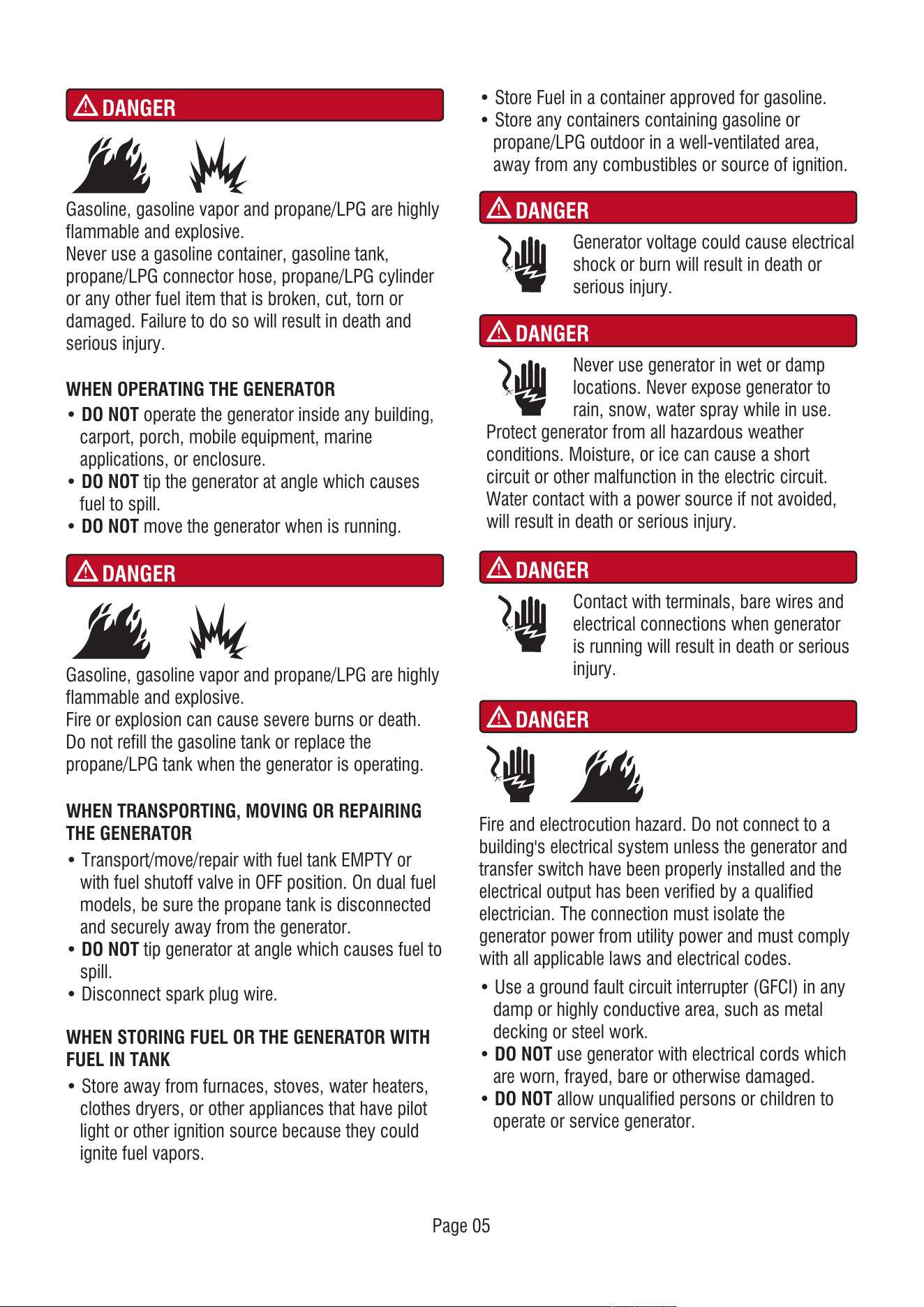
DANGER
Gasoline, gasoline vapor and propane/LPG are highly
flammable and explosive.
Never use a gasoline container, gasoline tank,
propane/LPG connector hose, propane/LPG cylinder
or any other fuel item that is broken, cut, torn or
damaged. Failure to do so will result in death and
serious injury.
DANGER
Gasoline, gasoline vapor and propane/LPG are highly
flammable and explosive.
Fire or explosion can cause severe burns or death.
Do not refill the gasoline tank or replace the
propane/LPG tank when the generator is operating.
• Use a ground fault circuit interrupter (GFCI) in any
damp or highly conductive area, such as metal
decking or steel work.
• DO NOT use generator with electrical cords which
are worn, frayed, bare or otherwise damaged.
• DO NOT allow unqualified persons or children to
operate or service generator.
DANGER
Contact with terminals, bare wires and
electrical connections when generator
is running will result in death or serious
injury.
DANGER
Fire and electrocution hazard. Do not connect to a
building's electrical system unless the generator and
transfer switch have been properly installed and the
electrical output has been verified by a qualified
electrician. The connection must isolate the
generator power from utility power and must comply
with all applicable laws and electrical codes.
WHEN OPERATING THE GENERATOR
• DO NOT operate the generator inside any building,
carport, porch, mobile equipment, marine
applications, or enclosure.
• DO NOT tip the generator at angle which causes
fuel to spill.
• DO NOT move the generator when is running.
DANGER
WHEN TRANSPORTING, MOVING OR REPAIRING
THE GENERATOR
• Transport/move/repair with fuel tank EMPTY or
with fuel shutoff valve in OFF position. On dual fuel
models, be sure the propane tank is disconnected
and securely away from the generator.
• DO NOT tip generator at angle which causes fuel to
spill.
• Disconnect spark plug wire.
WHEN STORING FUEL OR THE GENERATOR WITH
FUEL IN TANK
• Store away from furnaces, stoves, water heaters,
clothes dryers, or other appliances that have pilot
light or other ignition source because they could
ignite fuel vapors.
• Store Fuel in a container approved for gasoline.
• Store any containers containing gasoline or
propane/LPG outdoor in a well-ventilated area,
away from any combustibles or source of ignition.
Generator voltage could cause electrical
shock or burn will result in death or
serious injury.
DANGER
Never use generator in wet or damp
locations. Never expose generator to
rain, snow, water spray while in use.
Protect generator from all hazardous weather
conditions. Moisture, or ice can cause a short
circuit or other malfunction in the electric circuit.
Water contact with a power source if not avoided,
will result in death or serious injury.
Page 05
Page 06
WARNING
WARNING
WARNING
When operating machine, do not touch
hot surfaces. Keep machine away from
combustibles during use. Hot surfaces
could result in severe burns or fire.
WARNING
WHEN ADJUSTING OR MAKING REPAIRS TO
YOUR GENERATOR
• Disconnect the spark plug wire from the spark plug
and place the wire where it cannot contact spark
plug.
WHEN TESTING FOR ENGINE SPARK
• Use approved spark plug tester.
• DO NOT check for spark with spark plug removed.
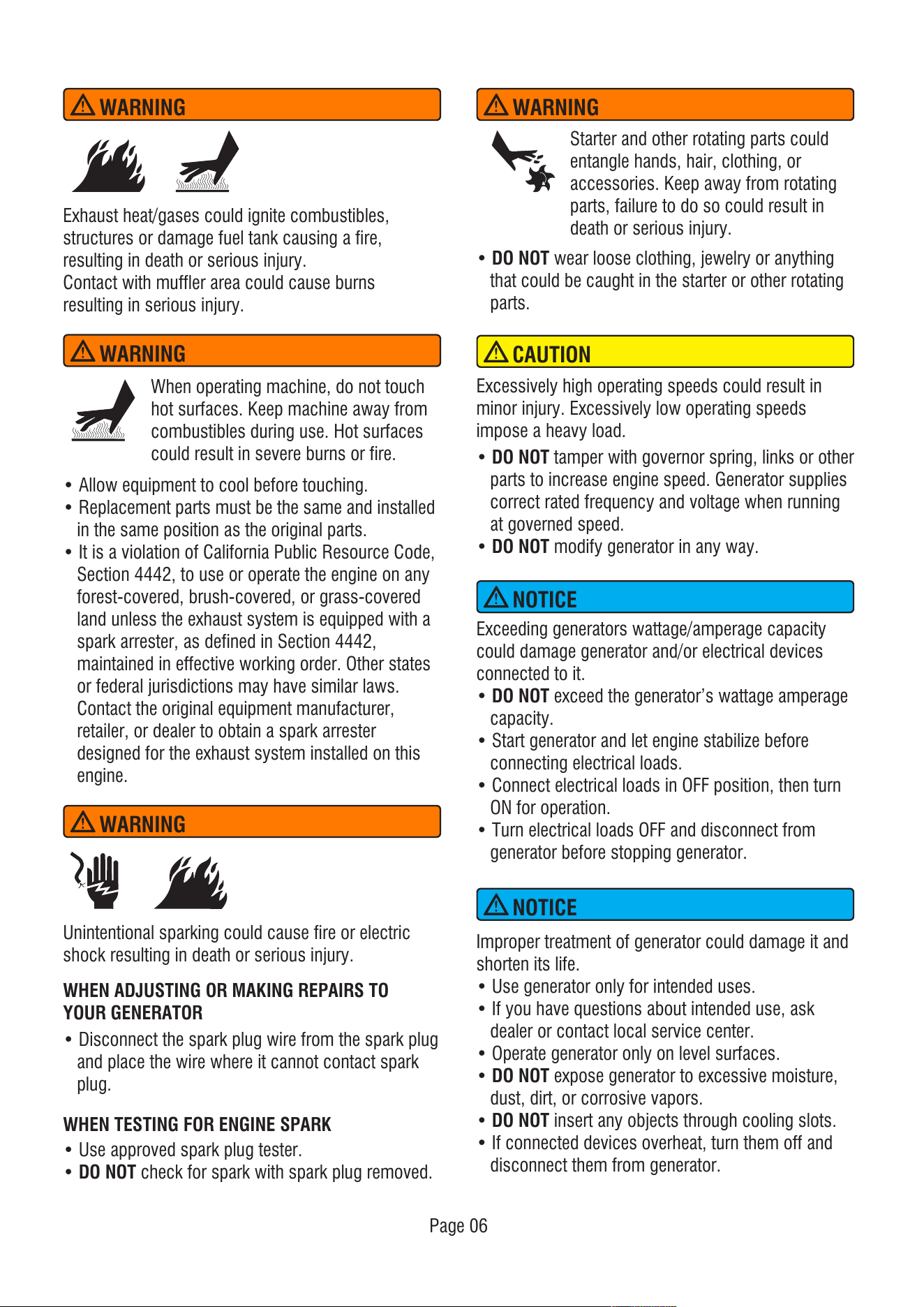
Exhaust heat/gases could ignite combustibles,
structures or damage fuel tank causing a fire,
resulting in death or serious injury.
Contact with muffler area could cause burns
resulting in serious injury.
• Allow equipment to cool before touching.
• Replacement parts must be the same and installed
in the same position as the original parts.
• It is a violation of California Public Resource Code,
Section 4442, to use or operate the engine on any
forest-covered, brush-covered, or grass-covered
land unless the exhaust system is equipped with a
spark arrester, as defined in Section 4442,
maintained in effective working order. Other states
or federal jurisdictions may have similar laws.
Contact the original equipment manufacturer,
retailer, or dealer to obtain a spark arrester
designed for the exhaust system installed on this
engine.
• DO NOT wear loose clothing, jewelry or anything
that could be caught in the starter or other rotating
parts.
Starter and other rotating parts could
entangle hands, hair, clothing, or
accessories. Keep away from rotating
parts, failure to do so could result in
death or serious injury.
Unintentional sparking could cause fire or electric
shock resulting in death or serious injury.
• DO NOT tamper with governor spring, links or other
parts to increase engine speed. Generator supplies
correct rated frequency and voltage when running
at governed speed.
• DO NOT modify generator in any way.
Excessively high operating speeds could result in
minor injury. Excessively low operating speeds
impose a heavy load.
Exceeding generators wattage/amperage capacity
could damage generator and/or electrical devices
connected to it.
• DO NOT exceed the generator’s wattage amperage
capacity.
• Start generator and let engine stabilize before
connecting electrical loads.
• Connect electrical loads in OFF position, then turn
ON for operation.
• Turn electrical loads OFF and disconnect from
generator before stopping generator.
CAUTION
NOTICE
NOTICE
Improper treatment of generator could damage it and
shorten its life.
• Use generator only for intended uses.
• If you have questions about intended use, ask
dealer or contact local service center.
• Operate generator only on level surfaces.
• DO NOT expose generator to excessive moisture,
dust, dirt, or corrosive vapors.
• DO NOT insert any objects through cooling slots.
• If connected devices overheat, turn them off and
disconnect them from generator.
• Shut off generator if:
-Electrical output is lost.
-Equipment sparks, smokes, or emits flames.
-Unit vibrates excessively.
• NEVER use this product to power life support
devices or life support appliances.
• NEVER use this product to power medical devices
or medical appliances.
• Inform your electricity provider immediately if you
or anyone in your household depends on electrical
equipment to live.
• Inform your electrical provider immediately if a loss
of power would cause you or anyone in your
household to experience a medical emergency.
Medical and Life Support Uses.
• In case of emergency, call 911 immediately.
WARNING
Page 07
Page 08
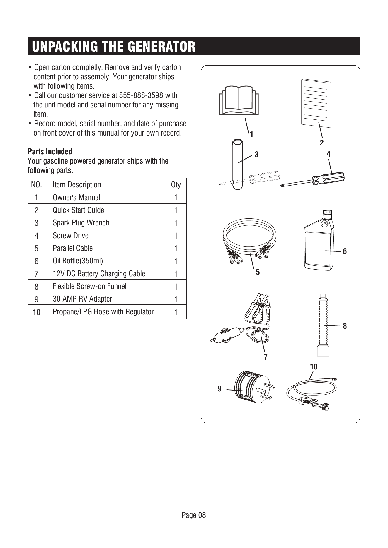
UNPACKING THE GENERATOR
Parts Included
Your gasoline powered generator ships with the
following parts:
• Open carton completly. Remove and verify carton
content prior to assembly. Your generator ships
with following items.
• Call our customer service at 855-888-3598 with
the unit model and serial number for any missing
item.
• Record model, serial number, and date of purchase
on front cover of this munual for your own record.
10
Parts Included
Your gasoline powered generator ships with the
following parts:
NO.
1
2
3
4
5
6
7
8
9
10
Qty
1
1
1
1
1
1
1
1
1
1
Item Description
Owner's Manual
Quick Start Guide
Spark Plug Wrench
Screw Drive
Parallel Cable
Oil Bottle(350ml)
12V DC Battery Charging Cable
Flexible Screw-on Funnel
30 AMP RV Adapter
Propane/LPG Hose with Regulator
1
3
5
7
9
4
6
8
2
Page 09
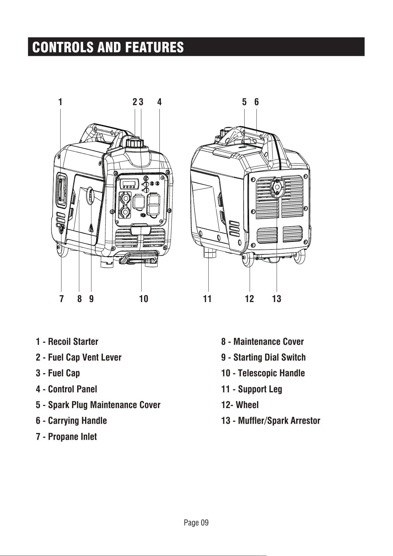
CONTROLS AND FEATURES
1 - Recoil Starter
2 - Fuel Cap Vent Lever
3 - Fuel Cap
4 - Control Panel
5 - Spark Plug Maintenance Cover
6 - Carrying Handle
7 - Propane Inlet
8 - Maintenance Cover
9 - Starting Dial Switch
10 - Telescopic Handle
11 - Support Leg
12- Wheel
13 - Muffler/Spark Arrestor
1 2 3 4 6
1312111098
7
5
Page 10
CONTROL PANEL FEATURES
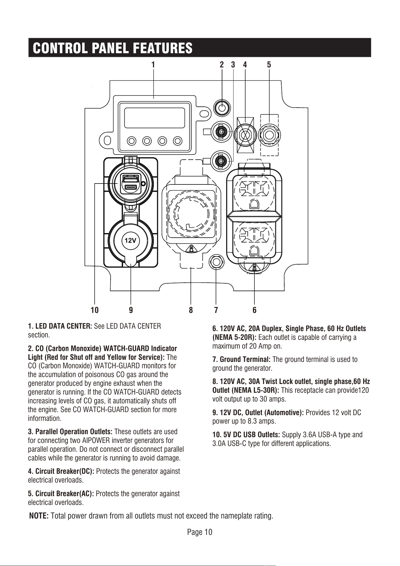
NOTE: Total power drawn from all outlets must not exceed the nameplate rating.
1. LED DATA CENTER: See LED DATA CENTER
section.
2. CO (Carbon Monoxide) WATCH-GUARD Indicator
Light (Red for Shut off and Yellow for Service): The
CO (Carbon Monoxide) WATCH-GUARD monitors for
the accumulation of poisonous CO gas around the
generator produced by engine exhaust when the
generator is running. If the CO WATCH-GUARD detects
increasing levels of CO gas, it automatically shuts off
the engine. See CO WATCH-GUARD section for more
information.
3. Parallel Operation Outlets: These outlets are used
for connecting two AIPOWER inverter generators for
parallel operation. Do not connect or disconnect parallel
cables while the generator is running to avoid damage.
4. Circuit Breaker(DC): Protects the generator against
electrical overloads.
5. Circuit Breaker(AC): Protects the generator against
electrical overloads.
6. 120V AC, 20A Duplex, Single Phase, 60 Hz Outlets
(NEMA 5-20R): Each outlet is capable of carrying a
maximum of 20 Amp on.
7. Ground Terminal: The ground terminal is used to
ground the generator.
8. 120V AC, 30A Twist Lock outlet, single phase,60 Hz
Outlet (NEMA L5-30R): This receptacle can provide120
volt output up to 30 amps.
9. 12V DC, Outlet (Automotive): Provides 12 volt DC
power up to 8.3 amps.
10. 5V DC USB Outlets: Supply 3.6A USB-A type and
3.0A USB-C type for different applications.
12V
1 2 43 5
6
78910
Page 11
CONTROL PANEL FEATURES
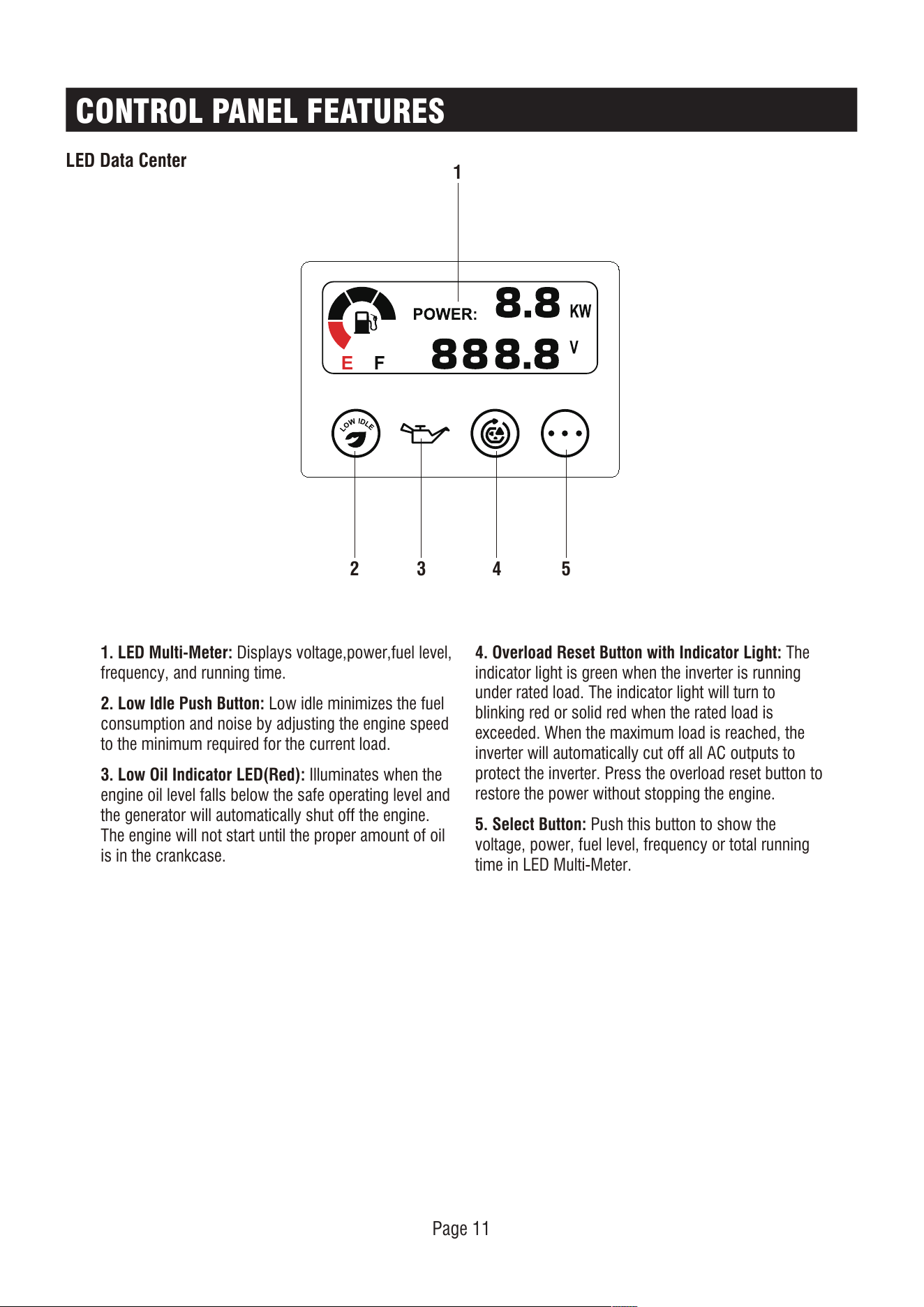
1. LED Multi-Meter: Displays voltage,power,fuel level,
frequency, and running time.
2. Low Idle Push Button: Low idle minimizes the fuel
consumption and noise by adjusting the engine speed
to the minimum required for the current load.
3. Low Oil Indicator LED(Red): Illuminates when the
engine oil level falls below the safe operating level and
the generator will automatically shut off the engine.
The engine will not start until the proper amount of oil
is in the crankcase.
4. Overload Reset Button with Indicator Light: The
indicator light is green when the inverter is running
under rated load. The indicator light will turn to
blinking red or solid red when the rated load is
exceeded. When the maximum load is reached, the
inverter will automatically cut off all AC outputs to
protect the inverter. Press the overload reset button to
restore the power without stopping the engine.
5. Select Button: Push this button to show the
voltage, power, fuel level, frequency or total running
time in LED Multi-Meter.
LED Data Center
2 3 4 5
1
Page 12
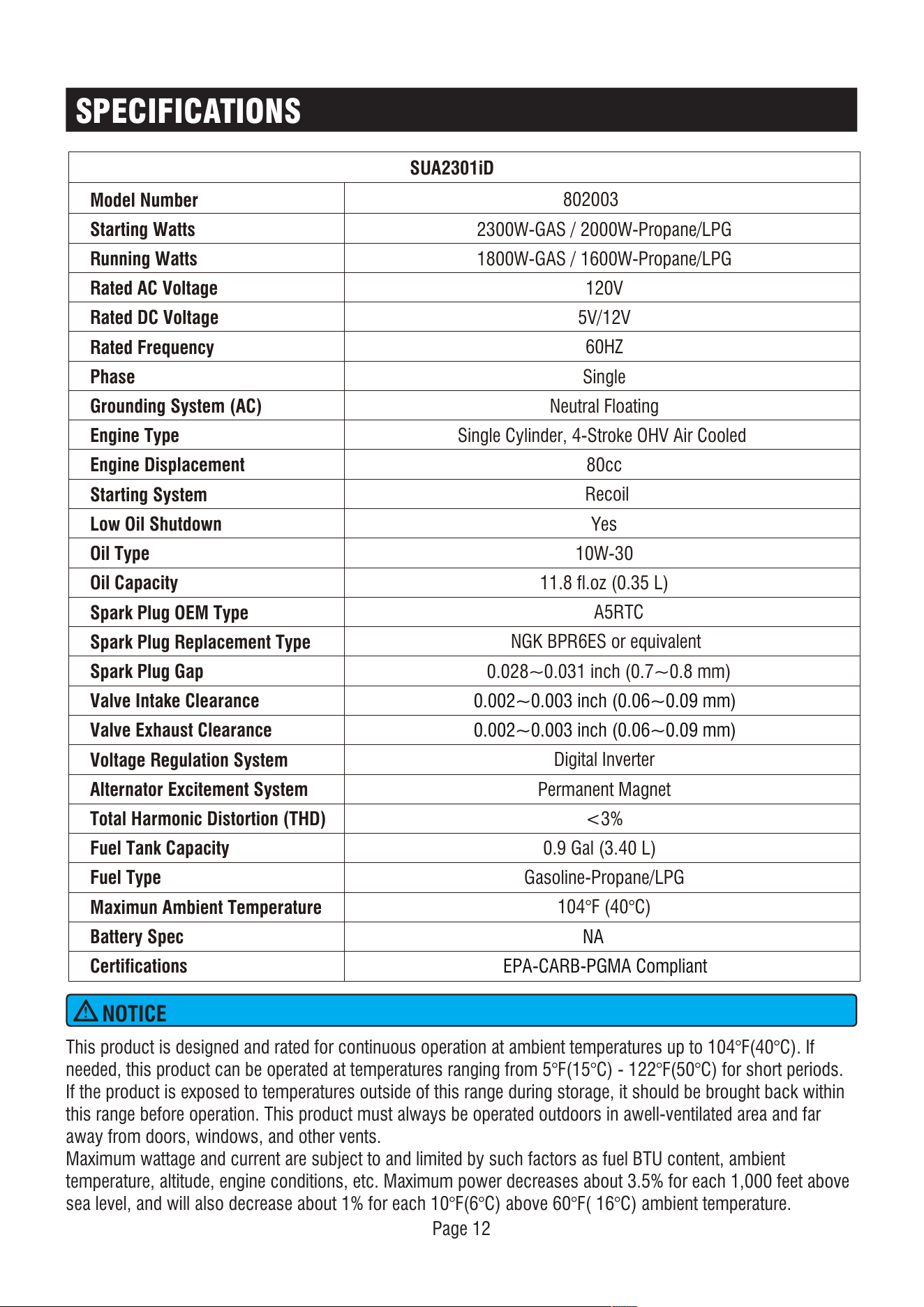
SPECIFICATIONS
NOTICE
This product is designed and rated for continuous operation at ambient temperatures up to 104°F(40°C). If
needed, this product can be operated at temperatures ranging from 5°F(15°C) - 122°F(50°C) for short periods.
If the product is exposed to temperatures outside of this range during storage, it should be brought back within
this range before operation. This product must always be operated outdoors in awell-ventilated area and far
away from doors, windows, and other vents.
Maximum wattage and current are subject to and limited by such factors as fuel BTU content, ambient
temperature, altitude, engine conditions, etc. Maximum power decreases about 3.5% for each 1,000 feet above
sea level, and will also decrease about 1% for each 10°F(6°C) above 60°F( 16°C) ambient temperature.
Model Number
SUA2301iD
Starting Watts
Running Watts
Rated AC Voltage
Rated DC Voltage
Rated Frequency
Phase
Grounding System (AC)
Engine Type
Engine Displacement
Starting System
Low Oil Shutdown
Oil Type
Oil Capacity
Spark Plug OEM Type
Spark Plug Replacement Type
Spark Plug Gap
Valve Intake Clearance
Valve Exhaust Clearance
Voltage Regulation System
Alternator Excitement System
Total Harmonic Distortion (THD)
Fuel Tank Capacity
Fuel Type
Maximun Ambient Temperature
Battery Spec
Certifications
802003
2300W-GAS / 2000W-Propane/LPG
1800W-GAS / 1600W-Propane/LPG
120V
5V/12V
60HZ
Single
Neutral Floating
Single Cylinder, 4-Stroke OHV Air Cooled
80cc
Recoil
Yes
10W-30
11.8 fl.oz (0.35 L)
A5RTC
NGK BPR6ES or equivalent
0.028~0.031 inch (0.7~0.8 mm)
0.002~0.003 inch (0.06~0.09 mm)
0.002~0.003 inch (0.06~0.09 mm)
Digital Inverter
Permanent Magnet
<3%
0.9 Gal (3.40 L)
Gasoline-Propane/LPG
104°F (40°C)
NA
EPA-CARB-PGMA Compliant
Page 13
CO WATCH-GUARD
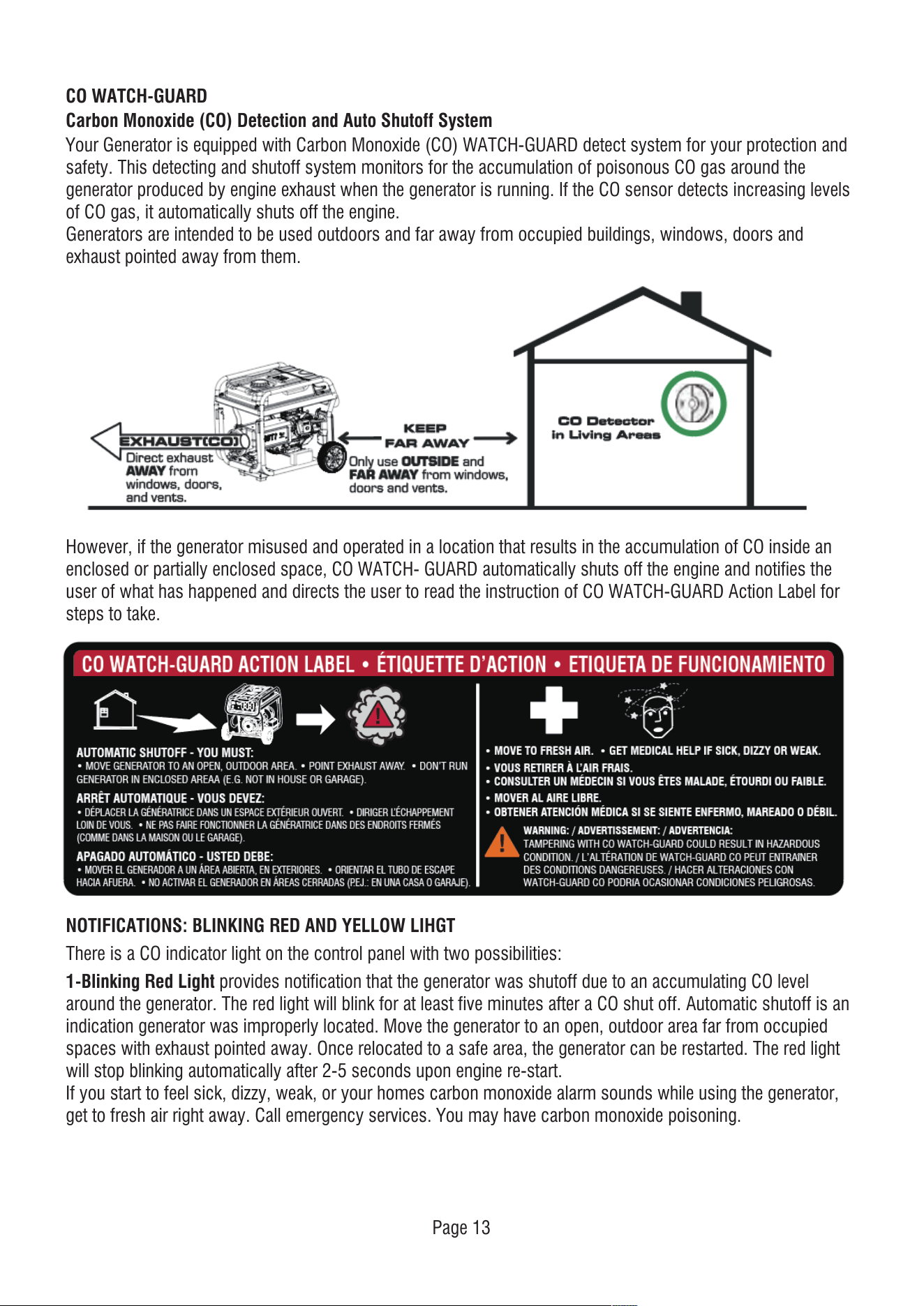
Carbon Monoxide (CO) Detection and Auto Shutoff System
Your Generator is equipped with Carbon Monoxide (CO) WATCH-GUARD detect system for your protection and
safety. This detecting and shutoff system monitors for the accumulation of poisonous CO gas around the
generator produced by engine exhaust when the generator is running. If the CO sensor detects increasing levels
of CO gas, it automatically shuts off the engine.
Generators are intended to be used outdoors and far away from occupied buildings, windows, doors and
exhaust pointed away from them.
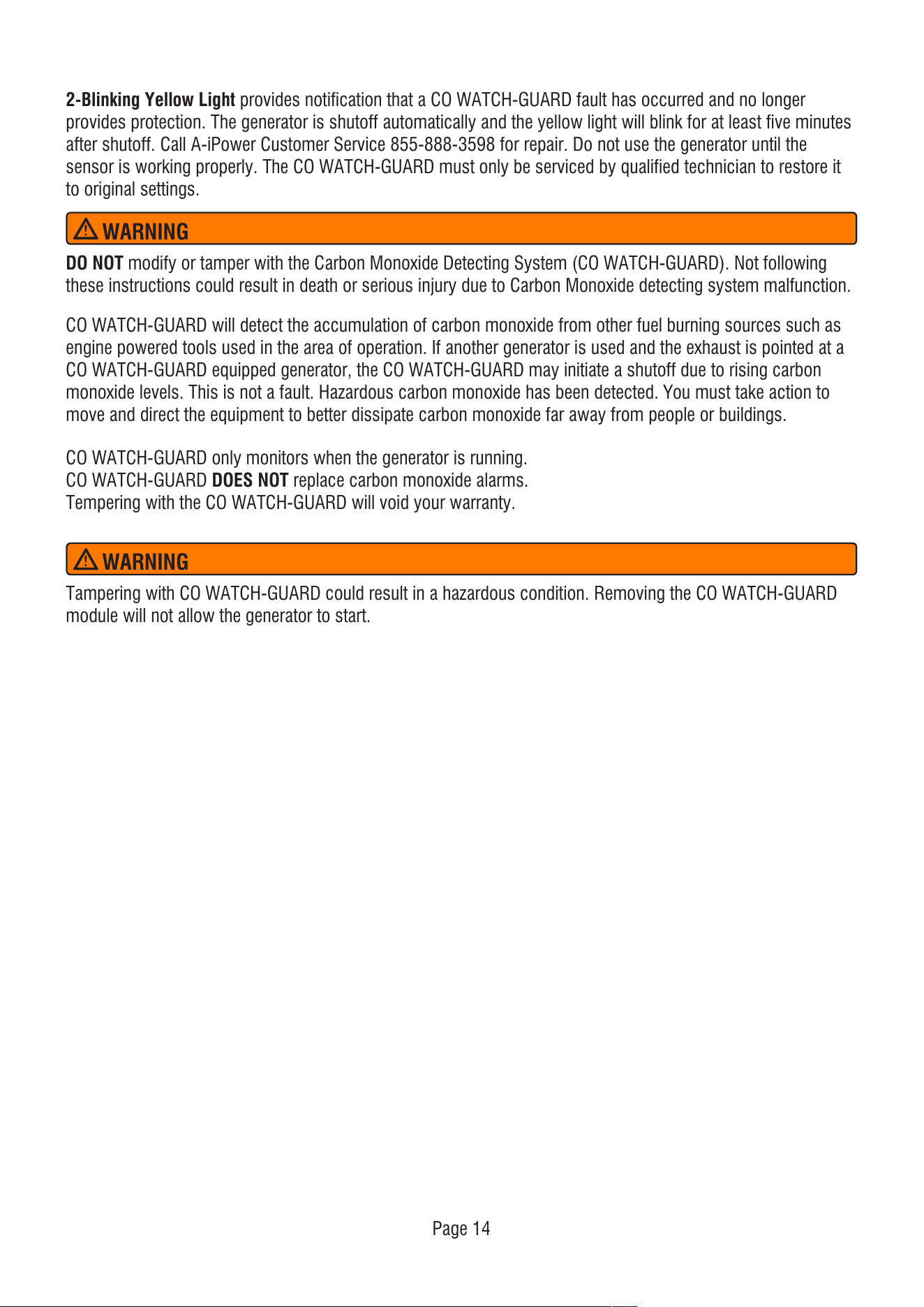
NOTIFICATIONS: BLINKING RED AND YELLOW LIHGT
There is a CO indicator light on the control panel with two possibilities:
1-Blinking Red Light provides notification that the generator was shutoff due to an accumulating CO level
around the generator. The red light will blink for at least five minutes after a CO shut off. Automatic shutoff is an
indication generator was improperly located. Move the generator to an open, outdoor area far from occupied
spaces with exhaust pointed away. Once relocated to a safe area, the generator can be restarted. The red light
will stop blinking automatically after 2-5 seconds upon engine re-start.
If you start to feel sick, dizzy, weak, or your homes carbon monoxide alarm sounds while using the generator,
get to fresh air right away. Call emergency services. You may have carbon monoxide poisoning.
However, if the generator misused and operated in a location that results in the accumulation of CO inside an
enclosed or partially enclosed space, CO WATCH- GUARD automatically shuts off the engine and notifies the
user of what has happened and directs the user to read the instruction of CO WATCH-GUARD Action Label for
steps to take.
2-Blinking Yellow Light provides notification that a CO WATCH-GUARD fault has occurred and no longer
provides protection. The generator is shutoff automatically and the yellow light will blink for at least five minutes
after shutoff. Call A-iPower Customer Service 855-888-3598 for repair. Do not use the generator until the
sensor is working properly. The CO WATCH-GUARD must only be serviced by qualified technician to restore it
to original settings.
Page 14
DO NOT modify or tamper with the Carbon Monoxide Detecting System (CO WATCH-GUARD). Not following
these instructions could result in death or serious injury due to Carbon Monoxide detecting system malfunction.
CO WATCH-GUARD will detect the accumulation of carbon monoxide from other fuel burning sources such as
engine powered tools used in the area of operation. If another generator is used and the exhaust is pointed at a
CO WATCH-GUARD equipped generator, the CO WATCH-GUARD may initiate a shutoff due to rising carbon
monoxide levels. This is not a fault. Hazardous carbon monoxide has been detected. You must take action to
move and direct the equipment to better dissipate carbon monoxide far away from people or buildings.
CO WATCH-GUARD only monitors when the generator is running.
CO WATCH-GUARD DOES NOT replace carbon monoxide alarms.
Tempering with the CO WATCH-GUARD will void your warranty.
WARNING
Tampering with CO WATCH-GUARD could result in a hazardous condition. Removing the CO WATCH-GUARD
module will not allow the generator to start.
WARNING
Page 15
Do not attempt to crank or start the engine before
it has been properly filled with the recommended
type and amount of oil. Damage due to operation
with no oil will void your warranty.
We consider the first 5 hours of run time to be the
break-in period for the unit. During the break in
period stay at or below 50% of the running watt
rating and vary the load occasionally to allow stator
windings to heat and cool. Adjusting the load will
also cause engine speed to vary and help seat piston
rings.
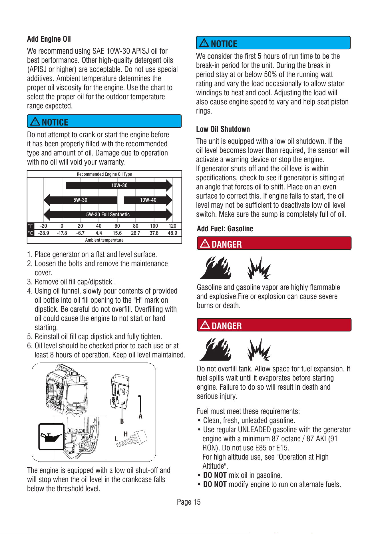
Add Engine Oil
We recommend using SAE 10W-30 APISJ oil for
best performance. Other high-quality detergent oils
(APISJ or higher) are acceptable. Do not use special
additives. Ambient temperature determines the
proper oil viscosity for the engine. Use the chart to
select the proper oil for the outdoor temperature
range expected.
Low Oil Shutdown
The unit is equipped with a low oil shutdown. If the
oil level becomes lower than required, the sensor will
activate a warning device or stop the engine.
If generator shuts off and the oil level is within
specifications, check to see if generator is sitting at
an angle that forces oil to shift. Place on an even
surface to correct this. If engine fails to start, the oil
level may not be sufficient to deactivate low oil level
switch. Make sure the sump is completely full of oil.
The engine is equipped with a low oil shut-off and
will stop when the oil level in the crankcase falls
below the threshold level.
1. Place generator on a flat and level surface.
2. Loosen the bolts and remove the maintenance
cover.
3. Remove oil fill cap/dipstick .
4. Using oil funnel, slowly pour contents of provided
oil bottle into oil fill opening to the "H" mark on
dipstick. Be careful do not overfill. Overfilling with
oil could cause the engine to not start or hard
starting.
5. Reinstall oil fill cap dipstick and fully tighten.
6. Oil level should be checked prior to each use or at
least 8 hours of operation. Keep oil level maintained.
-2 0 0 2 0 4 0 6 0
Ambient temperature
Recommended Engine Oil Type
8 0 1 00 1 2 0
-2 8 .9
° F
°C -1 7 .8 -6 .7 4 .4 1 5.6 2 6 .7 3 7 .8 4 8 .9
1 0W-3 0
5W-3 0 Full Synthetic
1 0W-4 05W-3 0
NOTICE
NOTICE
Add Fuel: Gasoline
Fuel must meet these requirements:
• Clean, fresh, unleaded gasoline.
• Use regular UNLEADED gasoline with the generator
engine with a minimum 87 octane / 87 AKI (91
RON). Do not use E85 or E15.
For high altitude use, see "Operation at High
Altitude".
• DO NOT mix oil in gasoline.
• DO NOT modify engine to run on alternate fuels.
DANGER
Gasoline and gasoline vapor are highly flammable
and explosive.Fire or explosion can cause severe
burns or death.
DANGER
Do not overfill tank. Allow space for fuel expansion. If
fuel spills wait until it evaporates before starting
engine. Failure to do so will result in death and
serious injury.
H
L
B
A
• The provided propane/LPG hose with regulator,
works with standard 20, 30 and 40 pound capacity
cylinders with Type 1, right hand Acme threads.
Verify the re-qualification date on the tank has not
expired. Do not use rusted or damaged cylinders.
• Only use provided propane/LPG hose for safe
propane operation.
1. Make certain both gasoline and propane/LPG
valves are closed.
2. Remove the rubber protective plugs (if it is avaiable)
and attach the propane/LPG hose with regulator to
the propane/LPG inlet located on the side control
panel of the generator. Tighten with a 19mm or
adjustable wrench. DO NOT over-tighten.
3. Remove safety plug from the propane/LPG cylinder
valve (if it is available) and attach the other end of
the propane/LPG hose with regulator to cylinder
valve. Tighten the nut by hand clockwise to a
positive stop.
WHEN ADDING GASOLINE
• Only fill the gasoline tank outdoors in a
well-ventilated area.
• DO NOT overfill gasoline tank. Allow space for fuel
expansion.
• If gasoline spills, wipe spilled gasoline from the unit
or wait until it evaporates before starting engine.
• Keep fuel away from sparks, open flames, pilot
lights, heat, and other ignition sources.
• Check fuel lines, tank, cap, and fittings frequently
for cracks or leaks. Replace if necessary.
• DO NOT light a cigarette or smoke.
• DO NOT fill the tank when the generator is running
or hot.
• DO NOT pump gasoline directly into the generator
at the gas station. Use an approved container to
transfer the gasoline to the generator.
• Only fill the tank from an approved gasoline
container. Make sure the gasoline container is
internally clean and in good condition to prevent
fuel system contamination.
• Gasoline can damage paint and plastic. Use
caution when filling the fuel tank. Damage caused
by spilled gasoline is not covered under warranty.
• Clean the fuel screen filter of debris before and
after each fueling. Remove the fuel screen filter by
slightly compressing it while removing it from the
fuel tank.
• It is important to prevent gum deposits from
forming in fuel system parts such as the carburetor,
fuel hose or tank during storage. Alcohol-blended
fuels (called gasohol, ethanol or methanol) can
attract moisture, which leads to separation and
formation of acids during storage. Acidic gas can
damage the fuel system of an engine while in
storage. To avoid engine problems, the fuel system
should be emptied before storage of 30 days or
longer. See the "Long Term Storage" section. Never
use engine or carburetor cleaner products in the
fuel tank as permanent damage may occur.
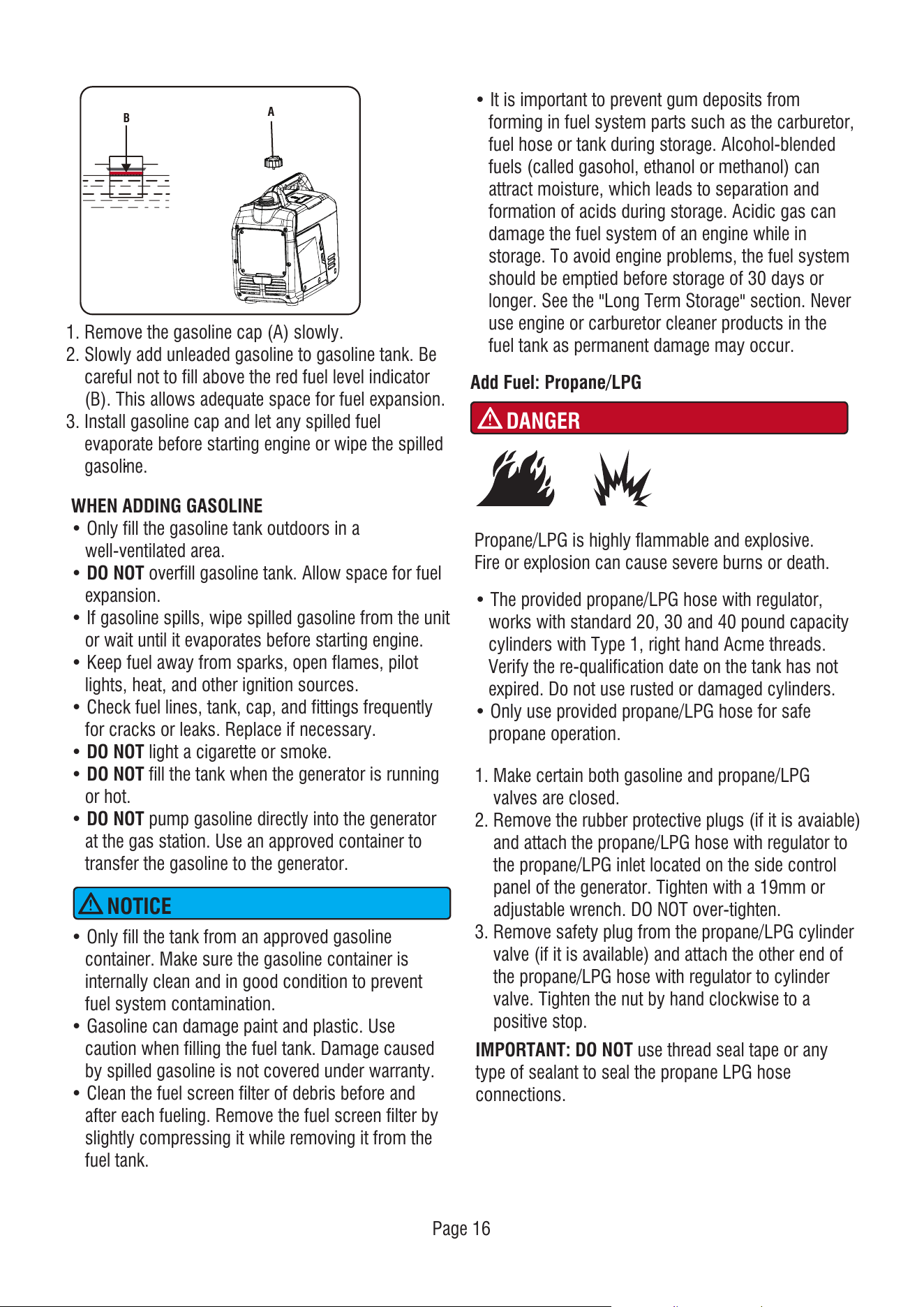
1. Remove the gasoline cap (A) slowly.
2. Slowly add unleaded gasoline to gasoline tank. Be
careful not to fill above the red fuel level indicator
(B). This allows adequate space for fuel expansion.
3. Install gasoline cap and let any spilled fuel
evaporate before starting engine or wipe the spilled
gasoline.
Page 16
NOTICE
Add Fuel: Propane/LPG
DANGER
Propane/LPG is highly flammable and explosive.
Fire or explosion can cause severe burns or death.
IMPORTANT: DO NOT use thread seal tape or any
type of sealant to seal the propane LPG hose
connections.
B
A
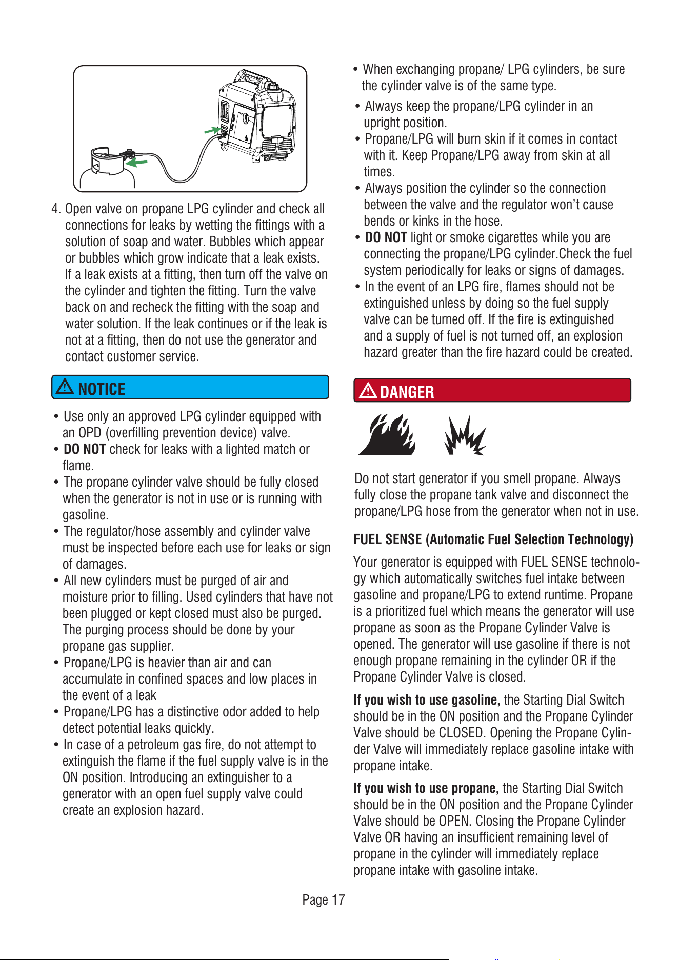
4. Open valve on propane LPG cylinder and check all
connections for leaks by wetting the fittings with a
solution of soap and water. Bubbles which appear
or bubbles which grow indicate that a leak exists.
If a leak exists at a fitting, then turn off the valve on
the cylinder and tighten the fitting. Turn the valve
back on and recheck the fitting with the soap and
water solution. If the leak continues or if the leak is
not at a fitting, then do not use the generator and
contact customer service.
NOTICE
• Use only an approved LPG cylinder equipped with
an OPD (overfilling prevention device) valve.
• DO NOT check for leaks with a lighted match or
flame.
• The propane cylinder valve should be fully closed
when the generator is not in use or is running with
gasoline.
• The regulator/hose assembly and cylinder valve
must be inspected before each use for leaks or sign
of damages.
• All new cylinders must be purged of air and
moisture prior to filling. Used cylinders that have not
been plugged or kept closed must also be purged.
The purging process should be done by your
propane gas supplier.
• Propane/LPG is heavier than air and can
accumulate in confined spaces and low places in
the event of a leak
• Propane/LPG has a distinctive odor added to help
detect potential leaks quickly.
• In case of a petroleum gas fire, do not attempt to
extinguish the flame if the fuel supply valve is in the
ON position. Introducing an extinguisher to a
generator with an open fuel supply valve could
create an explosion hazard.
• When exchanging propane/ LPG cylinders, be sure
the cylinder valve is of the same type.
• Always keep the propane/LPG cylinder in an
upright position.
• Propane/LPG will burn skin if it comes in contact
with it. Keep Propane/LPG away from skin at all
times.
• Always position the cylinder so the connection
between the valve and the regulator won’t cause
bends or kinks in the hose.
• DO NOT light or smoke cigarettes while you are
connecting the propane/LPG cylinder.Check the fuel
system periodically for leaks or signs of damages.
• In the event of an LPG fire, flames should not be
extinguished unless by doing so the fuel supply
valve can be turned off. If the fire is extinguished
and a supply of fuel is not turned off, an explosion
hazard greater than the fire hazard could be created.
DANGER
Do not start generator if you smell propane. Always
fully close the propane tank valve and disconnect the
propane/LPG hose from the generator when not in use.
Page 17
FUEL SENSE (Automatic Fuel Selection Technology)
Your generator is equipped with FUEL SENSE technolo-
gy which automatically switches fuel intake between
gasoline and propane/LPG to extend runtime. Propane
is a prioritized fuel which means the generator will use
propane as soon as the Propane Cylinder Valve is
opened. The generator will use gasoline if there is not
enough propane remaining in the cylinder OR if the
Propane Cylinder Valve is closed.
If you wish to use gasoline, the Starting Dial Switch
should be in the ON position and the Propane Cylinder
Valve should be CLOSED. Opening the Propane Cylin-
der Valve will immediately replace gasoline intake with
propane intake.
If you wish to use propane, the Starting Dial Switch
should be in the ON position and the Propane Cylinder
Valve should be OPEN. Closing the Propane Cylinder
Valve OR having an insufficient remaining level of
propane in the cylinder will immediately replace
propane intake with gasoline intake.
Operation using an alternative main jet at elevations
lower than the recommended minimum altitude can
damage the engine. For operation at lower elevations,
the standard main jet supplied must be used.
Operating the engine with the wrong main jet may
increase exhaust emissions, fuel consumption and
reduce performance.
Operation at High Altitude
At altitudes over 5,000 feet(1524 meters), a
minimum 85 octane gasoline is acceptable. Engine
power and generator output will be reduced
approximately 3.5% for every 1000 feet (305 m) of
elevation above sea level. High altitude may cause
hard starting, increased fuel consumption and spark
plug fouling. To operate at high altitudes A-iPower
can provide a high altitude carburetor main jet. The
alternative main jet and installation instructions can
be obtained by contacting Customer Support.
Grounding
The national electrical requires your generator must
be connected properly to an appropriate ground to
help prevent electric shock.
The generator has a system ground that connects the
generator frame components to the ground terminals
on the AC output receptacles. There may be Federal
or State regulations, local codes, or ordinances that
apply to the intended use of the generator. Consult a
qualified electrician, electrical inspector, or the local
agency having jurisdiction. This generator is not
intended to be used at a construction site or similar
activity as defined by NFPA 70-2020 (NEC) section
590.6.
Connecting to a Building's Electrical System
Connections to your home’s electrical system must
use a listed transfer switch installed by a licensed
electrician. The connection must isolate the generator
power from the utility power and comply with all
applicable laws and electrical codes.
Page 18
NOTICE
WARNING
Shock hazard. Failure to properly ground
the generator can result in electric shock.
OPERATION
Generator Location
Surge Protection
Make sure you review each warning in order to
prevent fire hazard.
• Keep area clear of inflammables or other
hazardous materials.
• Select a site that is dry, well ventilated and
protected from the weather.
• Keep exhaust pipe clear of foreign objects.
• Keep generator away from open flame.
• Keep generator on a stable and level surface.
• Do not block generator air vents with paper or
other material.
Electronic devices, including computers and many
programmable appliances use components that are
designed to operate within a narrow voltage range
and may be affected by momentary voltage
fluctuations. While there is no way to prevent voltage
fluctuations, you can take steps to protect sensitive
electronic equipment.
Install UL1449, CSA-listed, plug-in surge
suppressors on the outlets feeding your sensitive
equipment.
Using a generator indoors CAN KILL YOU IN MINUTES. Generator exhaust
contains carbon monoxide. This is a poison you cannot see or smell.
NEVER use inside a home or garage,
EVEN IF doors and windows are open.
Avoid other generator hazards. READ MANUAL BEFORE USE.
Only use OUTSIDE and far away
from windows, doors and vents.
WARNING
DANGER
Never use generator in wet or damp
locations. Never expose generator to
rain, snow, water spray or standing
water while in use. Protect generator
from all hazardous weather conditions.
Moisture, or ice can cause a short
circuit or other malfunction in the
electric circuit. Water contact with a
power source if not avoided, will result
in death or serious injury.
Page 19
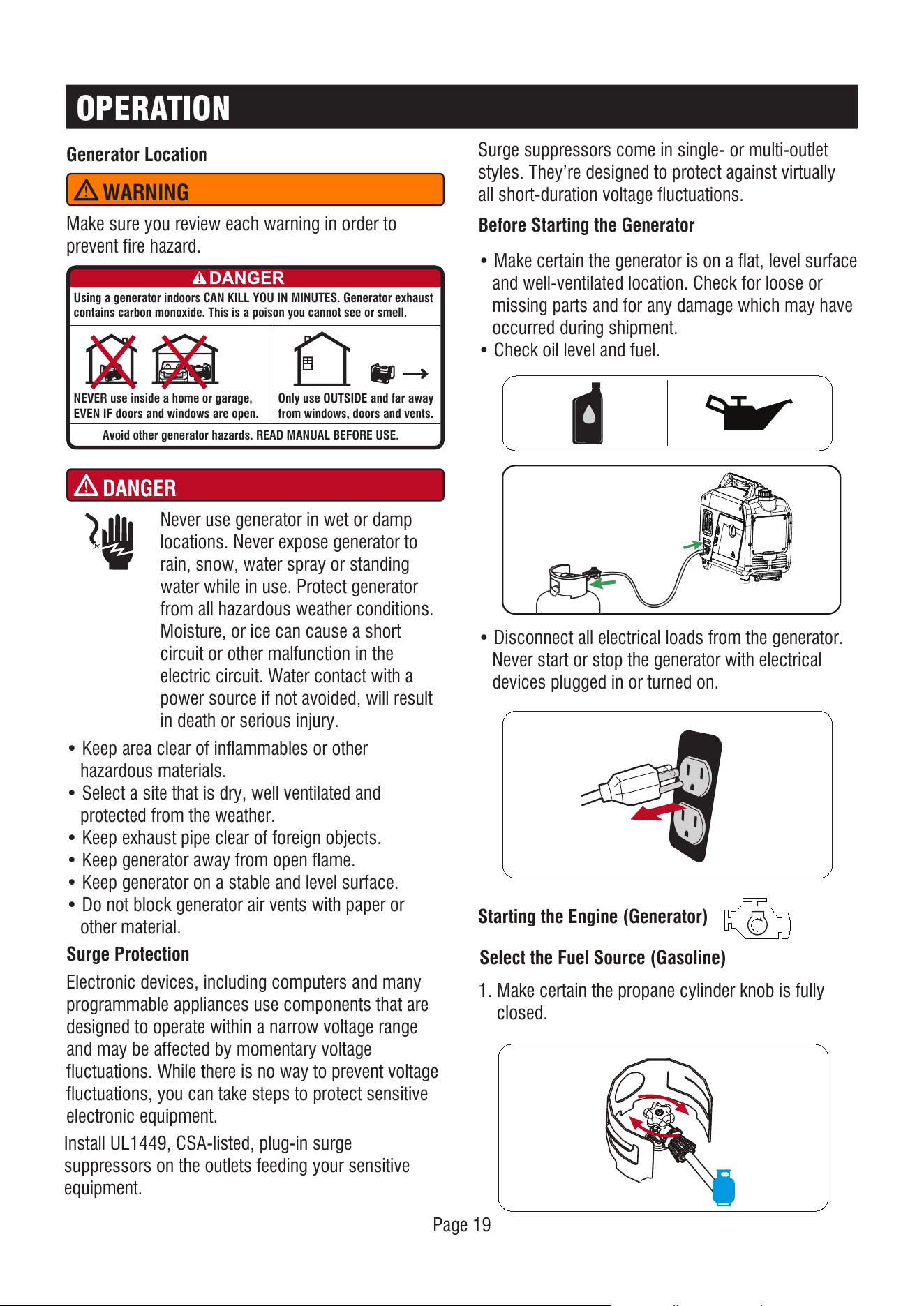
Before Starting the Generator
• Disconnect all electrical loads from the generator.
Never start or stop the generator with electrical
devices plugged in or turned on.
• Make certain the generator is on a flat, level surface
and well-ventilated location. Check for loose or
missing parts and for any damage which may have
occurred during shipment.
• Check oil level and fuel.
Starting the Engine (Generator)
Select the Fuel Source (Gasoline)
1. Make certain the propane cylinder knob is fully
closed.
Surge suppressors come in single- or multi-outlet
styles. They’re designed to protect against virtually
all short-duration voltage fluctuations.
Page 20
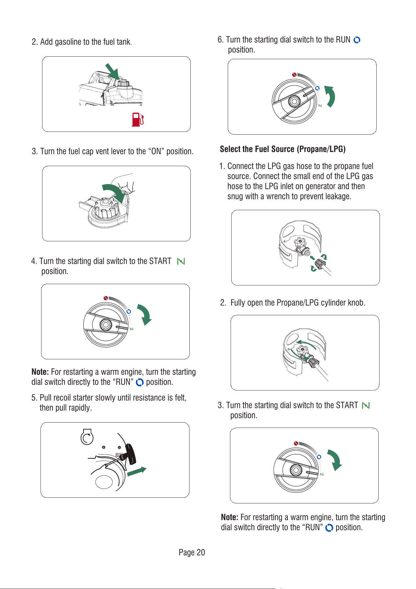
2. Add gasoline to the fuel tank.
3. Turn the fuel cap vent lever to the “ON” position.
6. Turn the starting dial switch to the RUN
position.
4. Turn the starting dial switch to the START
position.
5. Pull recoil starter slowly until resistance is felt,
then pull rapidly.
3. Turn the starting dial switch to the START
position.
Select the Fuel Source (Propane/LPG)
1. Connect the LPG gas hose to the propane fuel
source. Connect the small end of the LPG gas
hose to the LPG inlet on generator and then
snug with a wrench to prevent leakage.
2. Fully open the Propane/LPG cylinder knob.
Note: For restarting a warm engine, turn the starting
dial switch directly to the “RUN” position.
Note: For restarting a warm engine, turn the starting
dial switch directly to the “RUN” position.
ON
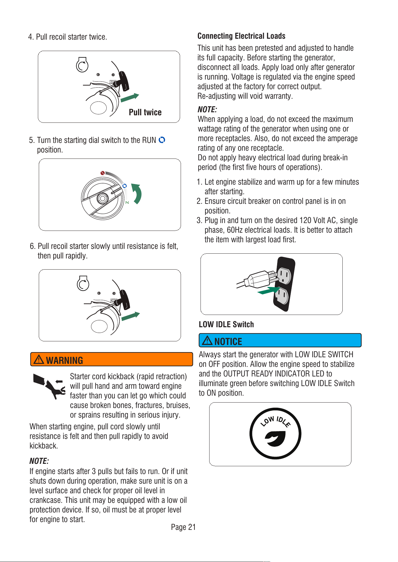
4. Pull recoil starter twice.
Pull twice
WARNING
NOTE:
If engine starts after 3 pulls but fails to run. Or if unit
shuts down during operation, make sure unit is on a
level surface and check for proper oil level in
crankcase. This unit may be equipped with a low oil
protection device. If so, oil must be at proper level
for engine to start.
When starting engine, pull cord slowly until
resistance is felt and then pull rapidly to avoid
kickback.
Starter cord kickback (rapid retraction)
will pull hand and arm toward engine
faster than you can let go which could
cause broken bones, fractures, bruises,
or sprains resulting in serious injury.
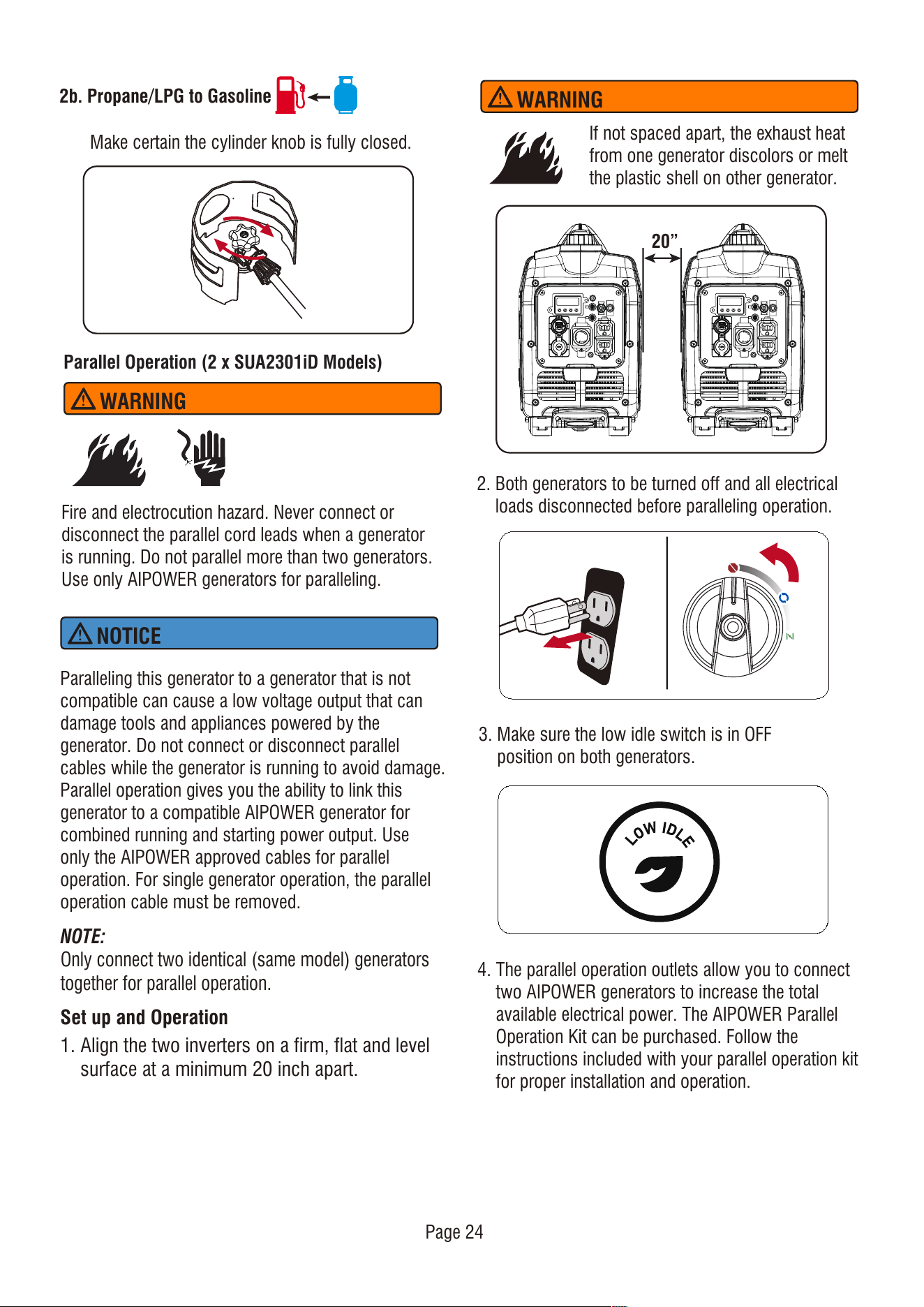
Connecting Electrical Loads
This unit has been pretested and adjusted to handle
its full capacity. Before starting the generator,
disconnect all loads. Apply load only after generator
is running. Voltage is regulated via the engine speed
adjusted at the factory for correct output.
Re-adjusting will void warranty.
NOTE:
When applying a load, do not exceed the maximum
wattage rating of the generator when using one or
more receptacles. Also, do not exceed the amperage
rating of any one receptacle.
Do not apply heavy electrical load during break-in
period (the first five hours of operations).
1. Let engine stabilize and warm up for a few minutes
after starting.
2. Ensure circuit breaker on control panel is in on
position.
3. Plug in and turn on the desired 120 Volt AC, single
phase, 60Hz electrical loads. It is better to attach
the item with largest load first.
LOW IDLE Switch
Always start the generator with LOW IDLE SWITCH
on OFF position. Allow the engine speed to stabilize
and the OUTPUT READY INDICATOR LED to
illuminate green before switching LOW IDLE Switch
to ON position.
NOTICE
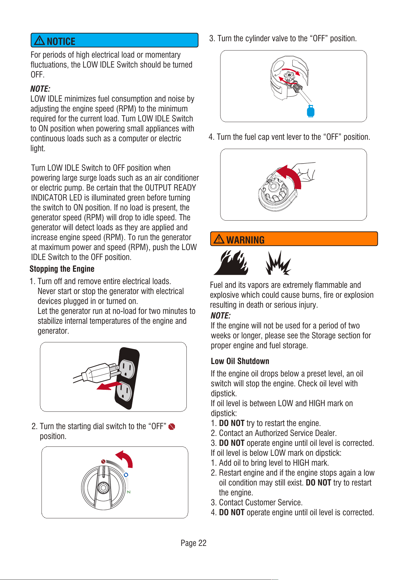
5. Turn the starting dial switch to the RUN
position.
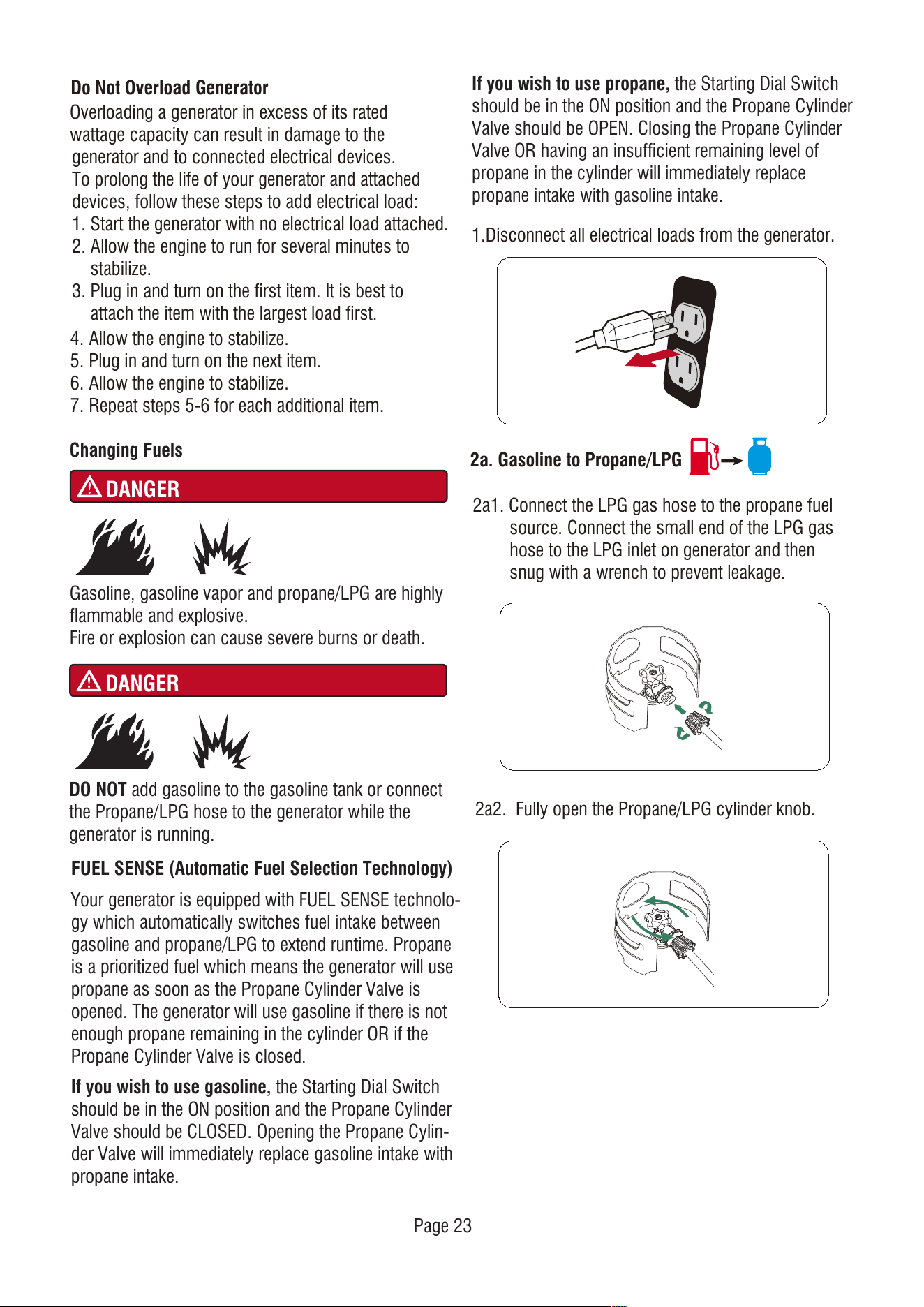
6. Pull recoil starter slowly until resistance is felt,
then pull rapidly.
Page 21
Turn LOW IDLE Switch to OFF position when
powering large surge loads such as an air conditioner
or electric pump. Be certain that the OUTPUT READY
INDICATOR LED is illuminated green before turning
the switch to ON position. If no load is present, the
generator speed (RPM) will drop to idle speed. The
generator will detect loads as they are applied and
increase engine speed (RPM). To run the generator
at maximum power and speed (RPM), push the LOW
IDLE Switch to the OFF position.
Stopping the Engine
1. Turn off and remove entire electrical loads.
Never start or stop the generator with electrical
devices plugged in or turned on.
Let the generator run at no-load for two minutes to
stabilize internal temperatures of the engine and
generator.
2. Turn the starting dial switch to the “OFF”
position.
3. Turn the cylinder valve to the “OFF” position.
4. Turn the fuel cap vent lever to the “OFF” position.
Fuel and its vapors are extremely flammable and
explosive which could cause burns, fire or explosion
resulting in death or serious injury.
WARNING
NOTE:
If the engine will not be used for a period of two
weeks or longer, please see the Storage section for
proper engine and fuel storage.
Low Oil Shutdown
If the engine oil drops below a preset level, an oil
switch will stop the engine. Check oil level with
dipstick.
If oil level is between LOW and HIGH mark on
dipstick:
1. DO NOT try to restart the engine.
2. Contact an Authorized Service Dealer.
3. DO NOT operate engine until oil level is corrected.
If oil level is below LOW mark on dipstick:
1. Add oil to bring level to HIGH mark.
2. Restart engine and if the engine stops again a low
oil condition may still exist. DO NOT try to restart
the engine.
3. Contact Customer Service.
4. DO NOT operate engine until oil level is corrected.
For periods of high electrical load or momentary
fluctuations, the LOW IDLE Switch should be turned
OFF.
NOTICE
Page 22
NOTE:
LOW IDLE minimizes fuel consumption and noise by
adjusting the engine speed (RPM) to the minimum
required for the current load. Turn LOW IDLE Switch
to ON position when powering small appliances with
continuous loads such as a computer or electric
light.
ON
OFF
Page 23
Do Not Overload Generator
Overloading a generator in excess of its rated
wattage capacity can result in damage to the
generator and to connected electrical devices.
To prolong the life of your generator and attached
devices, follow these steps to add electrical load:
1. Start the generator with no electrical load attached.
2. Allow the engine to run for several minutes to
stabilize.
3. Plug in and turn on the first item. It is best to
attach the item with the largest load first.
4. Allow the engine to stabilize.
5. Plug in and turn on the next item.
6. Allow the engine to stabilize.
7. Repeat steps 5-6 for each additional item.
Changing Fuels
DANGER
Gasoline, gasoline vapor and propane/LPG are highly
flammable and explosive.
Fire or explosion can cause severe burns or death.
DANGER
DO NOT add gasoline to the gasoline tank or connect
the Propane/LPG hose to the generator while the
generator is running.
2a1. Connect the LPG gas hose to the propane fuel
source. Connect the small end of the LPG gas
hose to the LPG inlet on generator and then
snug with a wrench to prevent leakage.
2a2. Fully open the Propane/LPG cylinder knob.
1.Disconnect all electrical loads from the generator.
2a. Gasoline to Propane/LPG
If you wish to use propane, the Starting Dial Switch
should be in the ON position and the Propane Cylinder
Valve should be OPEN. Closing the Propane Cylinder
Valve OR having an insufficient remaining level of
propane in the cylinder will immediately replace
propane intake with gasoline intake.
FUEL SENSE (Automatic Fuel Selection Technology)
Your generator is equipped with FUEL SENSE technolo-
gy which automatically switches fuel intake between
gasoline and propane/LPG to extend runtime. Propane
is a prioritized fuel which means the generator will use
propane as soon as the Propane Cylinder Valve is
opened. The generator will use gasoline if there is not
enough propane remaining in the cylinder OR if the
Propane Cylinder Valve is closed.
If you wish to use gasoline, the Starting Dial Switch
should be in the ON position and the Propane Cylinder
Valve should be CLOSED. Opening the Propane Cylin-
der Valve will immediately replace gasoline intake with
propane intake.
Parallel Operation (2 x SUA2301iD Models)
WARNING
Page 24
Make certain the cylinder knob is fully closed.
2b. Propane/LPG to Gasoline
Fire and electrocution hazard. Never connect or
disconnect the parallel cord leads when a generator
is running. Do not parallel more than two generators.
Use only AIPOWER generators for paralleling.
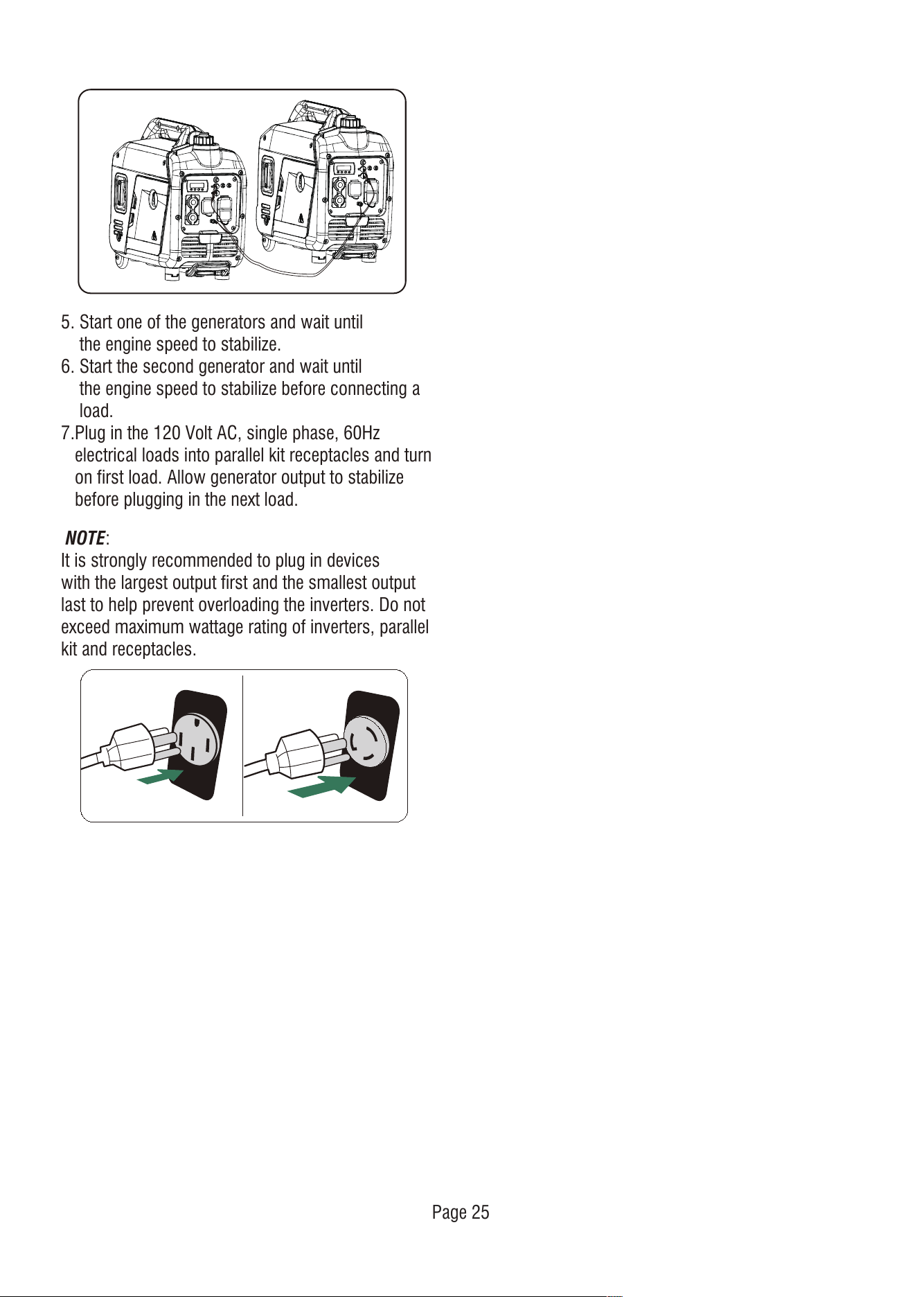
1. Align the two inverters on a firm, flat and level
surface at a minimum 20 inch apart.
Set up and Operation
NOTE:
Only connect two identical (same model) generators
together for parallel operation.
Paralleling this generator to a generator that is not
compatible can cause a low voltage output that can
damage tools and appliances powered by the
generator. Do not connect or disconnect parallel
cables while the generator is running to avoid damage.
Parallel operation gives you the ability to link this
generator to a compatible AIPOWER generator for
combined running and starting power output. Use
only the AIPOWER approved cables for parallel
operation. For single generator operation, the parallel
operation cable must be removed.
NOTICE
3. Make sure the low idle switch is in OFF
position on both generators.
4. The parallel operation outlets allow you to connect
two AIPOWER generators to increase the total
available electrical power. The AIPOWER Parallel
Operation Kit can be purchased. Follow the
instructions included with your parallel operation kit
for proper installation and operation.
WARNING
If not spaced apart, the exhaust heat
from one generator discolors or melt
the plastic shell on other generator.
2. Both generators to be turned off and all electrical
loads disconnected before paralleling operation.
20”
Page 25
NOTE:
It is strongly recommended to plug in devices
with the largest output first and the smallest output
last to help prevent overloading the inverters. Do not
exceed maximum wattage rating of inverters, parallel
kit and receptacles.
5. Start one of the generators and wait until
the engine speed to stabilize.
6. Start the second generator and wait until
the engine speed to stabilize before connecting a
load.
7.Plug in the 120 Volt AC, single phase, 60Hz
electrical loads into parallel kit receptacles and turn
on first load. Allow generator output to stabilize
before plugging in the next load.
MAINTENANCE AND STORAGE
MAINTENANCE SCHEDULE
Regular Maintenance will improve the performance
and extend the life of your generator. Follow
maintenance schedule intervals whichever occurs
first according to use.
Walk-Around Inspection
Before starting the engine perform a visual inspection
of the unit. Look for:
• Proper engine oil level
• Proper fuel level
• Fluid leaks
• Loose clamps and bolts
• Cracked fuel line
• Loose or frayed wiring
• Built up debris
NOTE: Adverse conditions will require more frequent
services.
General Recommendations
NOTE:
Maintenance should be performed more frequently
when generator is used in dusty areas.
When generator has exceeded the maximum figures
specified in the table, maintenance should still be
cycled according tothe intervals of time or hours
stated herein.
NOTE:
Change oil every month when operating under heavy
load or high temperatures. Clean the air filter more
often under dirty or dusty operating conditions.
Replace air filter if they cannot be adequately cleaned.
Regular maintenance will improve the performance
and extend the life of the generator. See any
authorized dealer for service.
The generator's warranty does not cover items that
have been subjected to operator abuse or negligence.
To receive full value from the warranty, the operator
must maintain generator as instructed in this manual.
Some adjustments will need to be made periodically
to properly maintain your generator. All service and
adjustments should be made at least once each
season. Follow the requirements in the Maintenanc
Shedule chart above.
ENGINE MAINTENANCE
CAUTION
To prevent accidental starting, remove and ground
spark plug wire before performing any service.
Engine Oil Level Check
Avoid skin contact with engine oil. Wear protective
clothing and equipment. Wash all exposed skin with
soap and water.
Before Each Use
* To be performed by authorized service center
Check engine oil level
Walk-around inspection
First 5 Hours (Break-In)
Change engine oil
First 25 Hours or First Month
Change engine oil
Every 100 Hours or 6 Months
Change engine oil
Clean Air Filter
Inspect/Adjust/Replace Spark plug
Inspect/Clean/Replace Spark Arrester
Every 200 Hours or 12 Months
Replace Air filter
Replace Spark Plug
Inspect/Adjust Valve Clearance*
Page 26
Page 27
-2 0 0 2 0 4 0 6 0
Ambient temperature
Recommended Engine Oil Type
8 0 1 00 1 2 0
-2 8 .9
° F
°C -1 7 .8 -6 .7 4 .4 1 5.6 2 6 .7 3 7 .8 4 8 .9
1 0W-3 0
5W-3 0 Full Synthetic
1 0W-4 05W-3 0
Change Engine Oil
Change engine oil per maintenance schedule.
If you are using your generator under extremely dirty
or dusty conditions, or in extremely hot weather,
change the oil more often.
CAUTION
Risk of burns. Allow engine to cool
before draining oil or coolant. Failure to
do so could result in death of serious
injury.
WARNING
Always use the specified engine oil. Failure to use the
specified engine oil can cause accelerated wear
and/or shorten the life of the engine.
When using the generator under extreme, dirty, dusty
conditions or in extremely hot weather, change the
oil more frequently.
Ambient air temperature will affect engine oil
performance. Change the type of engine oil used
based on weather conditions.
NOTICE
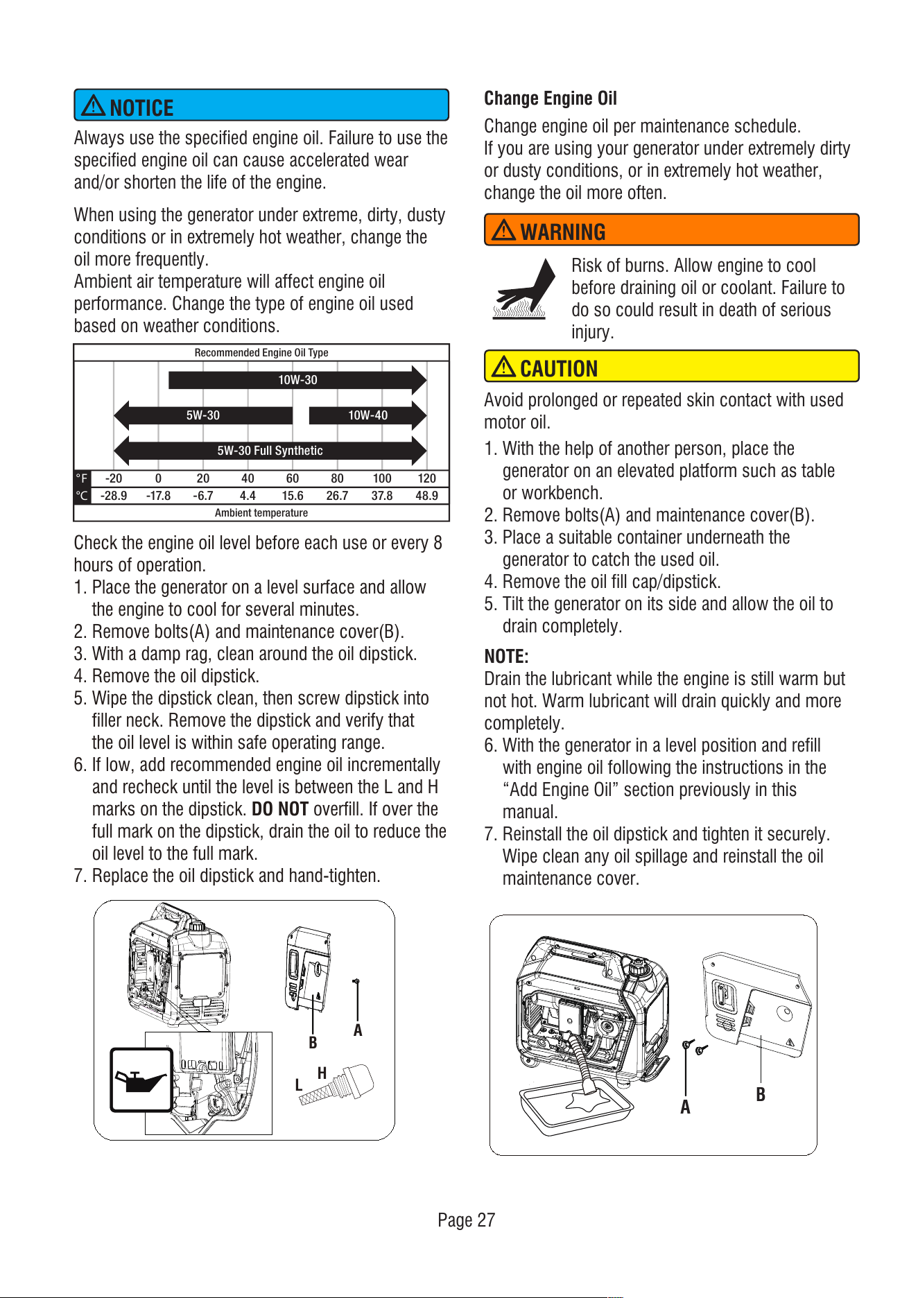
Check the engine oil level before each use or every 8
hours of operation.
1. Place the generator on a level surface and allow
the engine to cool for several minutes.
2. Remove bolts(A) and maintenance cover(B).
3. With a damp rag, clean around the oil dipstick.
4. Remove the oil dipstick.
5. Wipe the dipstick clean, then screw dipstick into
filler neck. Remove the dipstick and verify that
the oil level is within safe operating range.
6. If low, add recommended engine oil incrementally
and recheck until the level is between the L and H
marks on the dipstick. DO NOT overfill. If over the
full mark on the dipstick, drain the oil to reduce the
oil level to the full mark.
7. Replace the oil dipstick and hand-tighten.
H
L
B
A
Avoid prolonged or repeated skin contact with used
motor oil.
A
B
1. With the help of another person, place the
generator on an elevated platform such as table
or workbench.
2. Remove bolts(A) and maintenance cover(B).
3. Place a suitable container underneath the
generator to catch the used oil.
4. Remove the oil fill cap/dipstick.
5. Tilt the generator on its side and allow the oil to
drain completely.
NOTE:
Drain the lubricant while the engine is still warm but
not hot. Warm lubricant will drain quickly and more
completely.
6. With the generator in a level position and refill
with engine oil following the instructions in the
“Add Engine Oil” section previously in this
manual.
7. Reinstall the oil dipstick and tighten it securely.
Wipe clean any oil spillage and reinstall the oil
maintenance cover.
Page 28
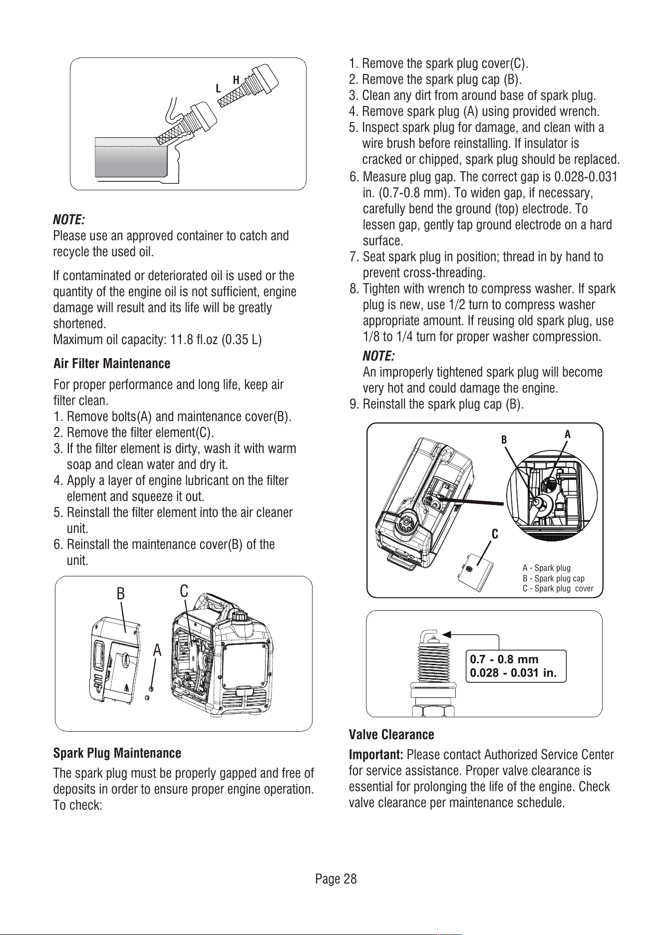
0.7 - 0.8 mm
0.028 - 0.031 in.
Air Filter Maintenance
NOTE:
Please use an approved container to catch and
recycle the used oil.
Spark Plug Maintenance
The spark plug must be properly gapped and free of
deposits in order to ensure proper engine operation.
To check:
If contaminated or deteriorated oil is used or the
quantity of the engine oil is not sufficient, engine
damage will result and its life will be greatly
shortened.
Maximum oil capacity: 11.8 fl.oz (0.35 L)
Valve Clearance
Important: Please contact Authorized Service Center
for service assistance. Proper valve clearance is
essential for prolonging the life of the engine. Check
valve clearance per maintenance schedule.
1. Remove the spark plug cover(C).
2. Remove the spark plug cap (B).
3. Clean any dirt from around base of spark plug.
4. Remove spark plug (A) using provided wrench.
5. Inspect spark plug for damage, and clean with a
wire brush before reinstalling. If insulator is
cracked or chipped, spark plug should be replaced.
6. Measure plug gap. The correct gap is 0.028-0.031
in. (0.7-0.8 mm). To widen gap, if necessary,
carefully bend the ground (top) electrode. To
lessen gap, gently tap ground electrode on a hard
surface.
7. Seat spark plug in position; thread in by hand to
prevent cross-threading.
8. Tighten with wrench to compress washer. If spark
plug is new, use 1/2 turn to compress washer
appropriate amount. If reusing old spark plug, use
1/8 to 1/4 turn for proper washer compression.
NOTE:
An improperly tightened spark plug will become
very hot and could damage the engine.
9. Reinstall the spark plug cap (B).
H
L
For proper performance and long life, keep air
filter clean.
1. Remove bolts(A) and maintenance cover(B).
2. Remove the filter element(C).
3. If the filter element is dirty, wash it with warm
soap and clean water and dry it.
4. Apply a layer of engine lubricant on the filter
element and squeeze it out.
5. Reinstall the filter element into the air cleaner
unit.
6. Reinstall the maintenance cover(B) of the
unit.
A
B
C
A
B
A - Spark plug
B - Spark plug cap
C - Spark plug cover
C
Page 29
Long Term Storage (over one year)
For long term storage, the gasoline tank and
carburetor must be drained of gasoline.
1 - After engine cools down, remove all gasoline
from the fuel tank using non-conductive siphon.
2 - To remove the remaining gasoline in fuel system:
a-Keep the fuel valve open and run the engine
until it stops from lack of fuel.
STORAGE
It is recommended to start and run the generator for
30 minutes, every 30 days. If this is not possible,
refer to below short term and long term storage.
Short Term Storage
Fill the tank with fresh gasoline and add gasoline
stabilizer. Drain the carburetor float bowl.
1 - Add a properly formulated FUEL STABILIZER to
the tank if it is not already added.
2 - Run the engine for 10-15 minutes to circulate
stabilizer throughout fuel system.
3 - Allow the generator to cool a minimum of 30
minutes and then drain the carburetor float bowl.
4 - Clean the generator and store in a cool, dry and
well ventilated area out of direct sunlight.
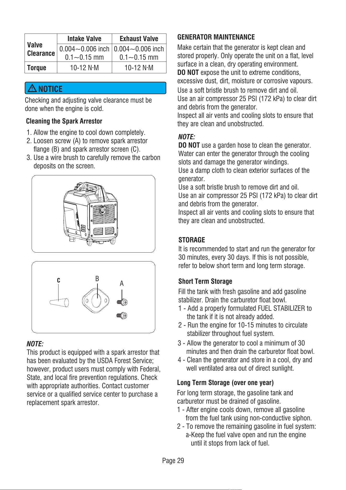
Checking and adjusting valve clearance must be
done when the engine is cold.
NOTICE
0.004~0.006 inch
0.1~0.15 mm
0.004~0.006 inch
0.1~0.15 mm
10-12 N·M 10-12 N·M
Intake Valve Exhaust Valve
Valve
Clearance
Torque
GENERATOR MAINTENANCE
Make certain that the generator is kept clean and
stored properly. Only operate the unit on a flat, level
surface in a clean, dry operating environment.
DO NOT expose the unit to extreme conditions,
excessive dust, dirt, moisture or corrosive vapours.
NOTE:
DO NOT use a garden hose to clean the generator.
Water can enter the generator through the cooling
slots and damage the generator windings.
Use a damp cloth to clean exterior surfaces of the
generator.
Use a soft bristle brush to remove dirt and oil.
Use an air compressor 25 PSI (172 kPa) to clear dirt
and debris from the generator.
Inspect all air vents and cooling slots to ensure that
they are clean and unobstructed.
Use a soft bristle brush to remove dirt and oil.
Use an air compressor 25 PSI (172 kPa) to clear dirt
and debris from the generator.
Inspect all air vents and cooling slots to ensure that
they are clean and unobstructed.
Cleaning the Spark Arrestor
NOTE:
This product is equipped with a spark arrestor that
has been evaluated by the USDA Forest Service;
however, product users must comply with Federal,
State, and local fire prevention regulations. Check
with appropriate authorities. Contact customer
service or a qualified service center to purchase a
replacement spark arrestor.
1. Allow the engine to cool down completely.
2. Loosen screw (A) to remove spark arrestor
flange (B) and spark arrestor screen (C).
3. Use a wire brush to carefully remove the carbon
deposits on the screen.
A
B
C
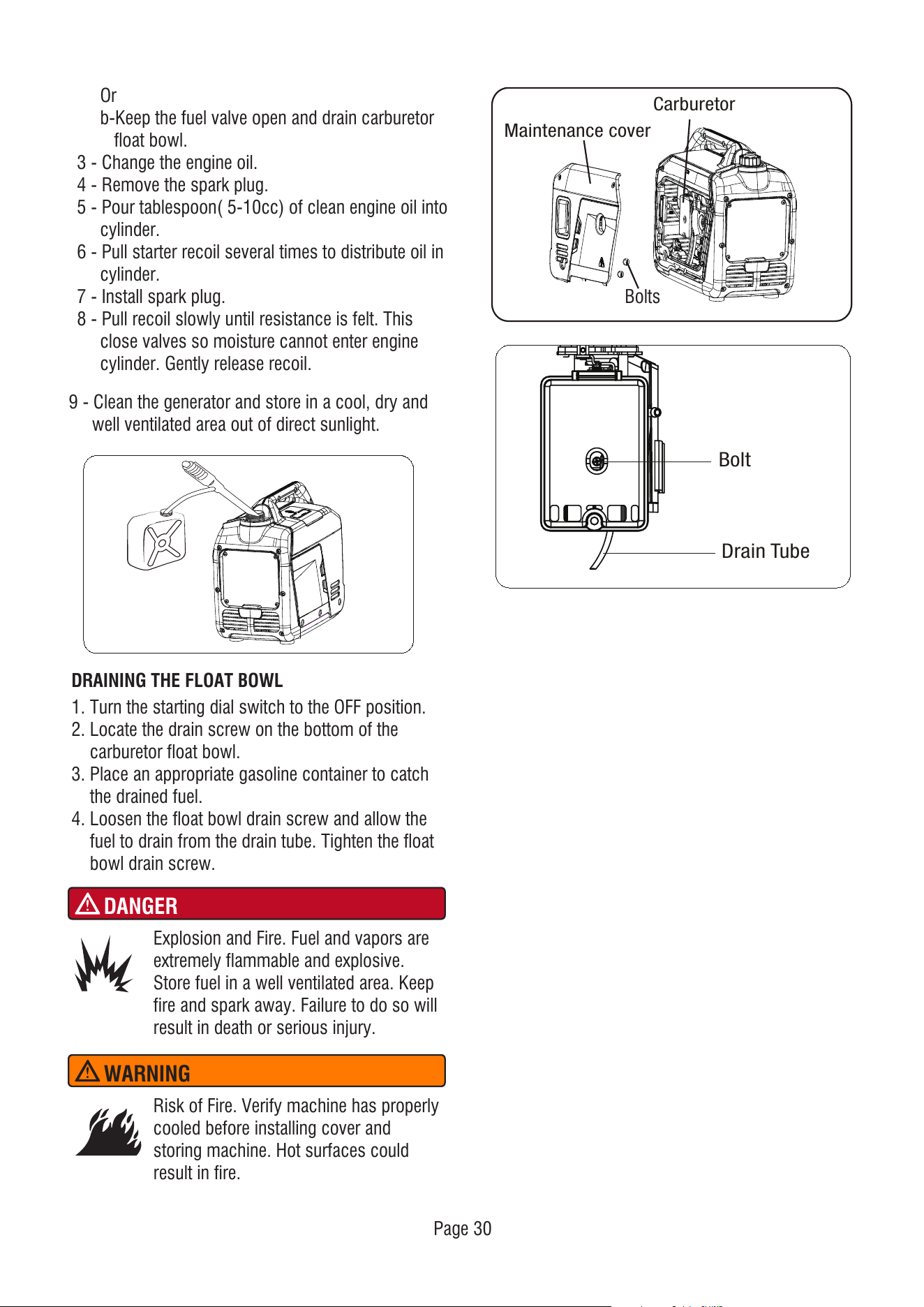
Or
b-Keep the fuel valve open and drain carburetor
float bowl.
3 - Change the engine oil.
4 - Remove the spark plug.
5 - Pour tablespoon( 5-10cc) of clean engine oil into
cylinder.
6 - Pull starter recoil several times to distribute oil in
cylinder.
7 - Install spark plug.
8 - Pull recoil slowly until resistance is felt. This
close valves so moisture cannot enter engine
cylinder. Gently release recoil.
DRAINING THE FLOAT BOWL
1. Turn the starting dial switch to the OFF position.
2. Locate the drain screw on the bottom of the
carburetor float bowl.
3. Place an appropriate gasoline container to catch
the drained fuel.
4. Loosen the float bowl drain screw and allow the
fuel to drain from the drain tube. Tighten the float
bowl drain screw.
DANGER
Explosion and Fire. Fuel and vapors are
extremely flammable and explosive.
Store fuel in a well ventilated area. Keep
fire and spark away. Failure to do so will
result in death or serious injury.
WARNING
Risk of Fire. Verify machine has properly
cooled before installing cover and
storing machine. Hot surfaces could
result in fire.
9 - Clean the generator and store in a cool, dry and
well ventilated area out of direct sunlight.
Drain Tube
Bolt
Carburetor
Bolts
Maintenance cover
Page 30
Page 31
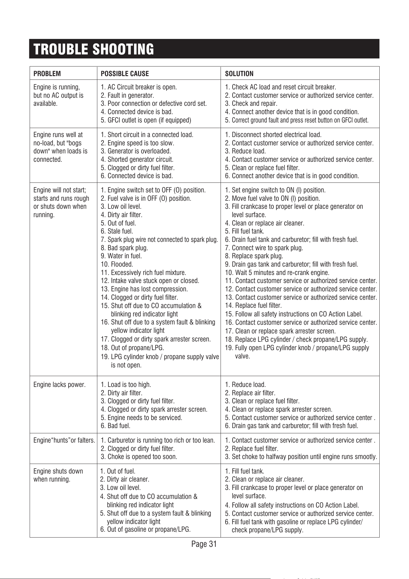
PROBLEM
Engine is running,
but no AC output is
available.
1. AC Circuit breaker is open.
2. Fault in generator.
3. Poor connection or defective cord set.
4. Connected device is bad.
5. GFCI outlet is open (if equipped)
1. Check AC load and reset circuit breaker.
2. Contact customer service or authorized service center.
3. Check and repair.
4. Connect another device that is in good condition.
5.
Correct ground fault and press reset button on GFCI outlet.
Engine runs well at
no-load, but "bogs
down" when loads is
connected.
1. Short circuit in a connected load.
2. Engine speed is too slow.
3. Generator is overloaded.
4. Shorted generator circuit.
5. Clogged or dirty fuel filter.
6. Connected device is bad.
1. Disconnect shorted electrical load.
2. Contact customer service or authorized service center.
3. Reduce load.
4. Contact customer service or authorized service center.
5. Clean or replace fuel filter.
6. Connect another device that is in good condition.
Engine will not start;
starts and runs rough
or shuts down when
running.
1. Engine switch set to OFF (O) position.
2. Fuel valve is in OFF (O) position.
3. Low oil level.
4. Dirty air filter.
5. Out of fuel.
6. Stale fuel.
7.
Spark plug wire not connected to spark plug.
8. Bad spark plug.
9. Water in fuel.
10. Flooded.
11. Excessively rich fuel mixture.
12. Intake valve stuck open or closed.
13. Engine has lost compression.
14. Clogged or dirty fuel filter.
1. Set engine switch to ON (l) position.
2. Move fuel valve to ON (l) position.
3. Fill crankcase to proper level or place generator on
level surface.
4. Clean or replace air cleaner.
5. Fill fuel tank.
6. Drain fuel tank and carburetor; fill with fresh fuel.
7. Connect wire to spark plug.
8. Replace spark plug.
9. Drain gas tank and carburetor; fill with fresh fuel.
10. Wait 5 minutes and re-crank engine.
11. Contact customer service or authorized service center.
12. Contact customer service or authorized service center.
13. Contact customer service or authorized service center.
14. Replace fuel filter.
Engine lacks power. 1. Load is too high.
2. Dirty air filter.
3. Clogged or dirty fuel filter.
4. Clogged or dirty spark arrester screen.
5. Engine needs to be serviced.
6. Bad fuel.
17. Clogged or dirty spark arrester screen.
18. Out of propane/LPG.
19. LPG cylinder knob / propane supply valve
is not open.
17. Clean or replace spark arrester screen.
1. Reduce load.
2. Replace air filter.
3. Clean or replace fuel filter.
4. Clean or replace spark arrester screen.
5. Contact customer service or authorized service center .
6. Drain gas tank and carburetor; fill with fresh fuel.
Engine“hunts”or falters. 1. Carburetor is running too rich or too lean.
2. Clogged or dirty fuel filter.
3. Choke is opened too soon.
1. Contact customer service or authorized service center .
2. Replace fuel filter.
3. Set choke to halfway position until engine runs smootly.
Engine shuts down
when running.
1. Out of fuel.
2. Dirty air cleaner.
3. Low oil level.
1. Fill fuel tank.
2. Clean or replace air cleaner.
3. Fill crankcase to proper level or place generator on
level surface.
POSSIBLE CAUSE SOLUTION
TROUBLE SHOOTING
4. Shut off due to CO accumulation &
blinking red indicator light
5. Shut off due to a system fault & blinking
yellow indicator light
4. Follow all safety instructions on CO Action Label.
5. Contact customer service or authorized service center.
15. Shut off due to CO accumulation &
blinking red indicator light
16. Shut off due to a system fault & blinking
yellow indicator light
15. Follow all safety instructions on CO Action Label.
16. Contact customer service or authorized service center.
18. Replace LPG cylinder / check propane/LPG supply.
19. Fully open LPG cylinder knob / propane/LPG supply
valve.
6. Out of gasoline or propane/LPG.
6. Fill fuel tank with gasoline or replace LPG cylinder/
check propane/LPG supply.
Page 32
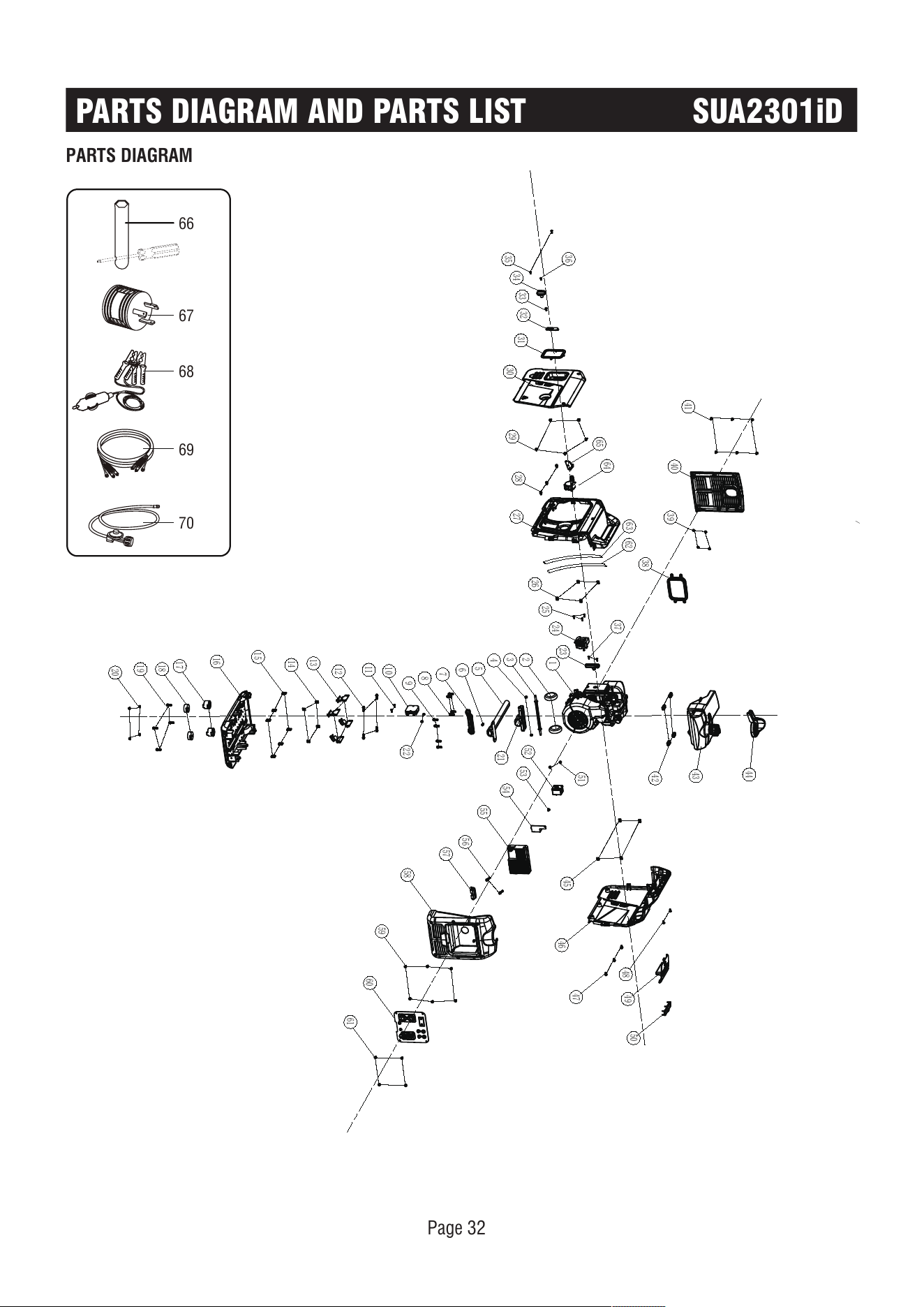
PARTS DIAGRAM
PARTS DIAGRAM AND PARTS LIST SUA2301iD
1
2
3
4
5
7
8
9
10
11
12
13
14
15
16
17
18
19
20
61
60
59
58
57
56
55
54
53
52
51
6
22
21
23
24
25
26
27
28
29
30
31
32
33
34
35
36
37
38
39
40
41
42
43
44
45
46
47
49
50
48
64
62
65
63
66
67
68
69
70
Page 33
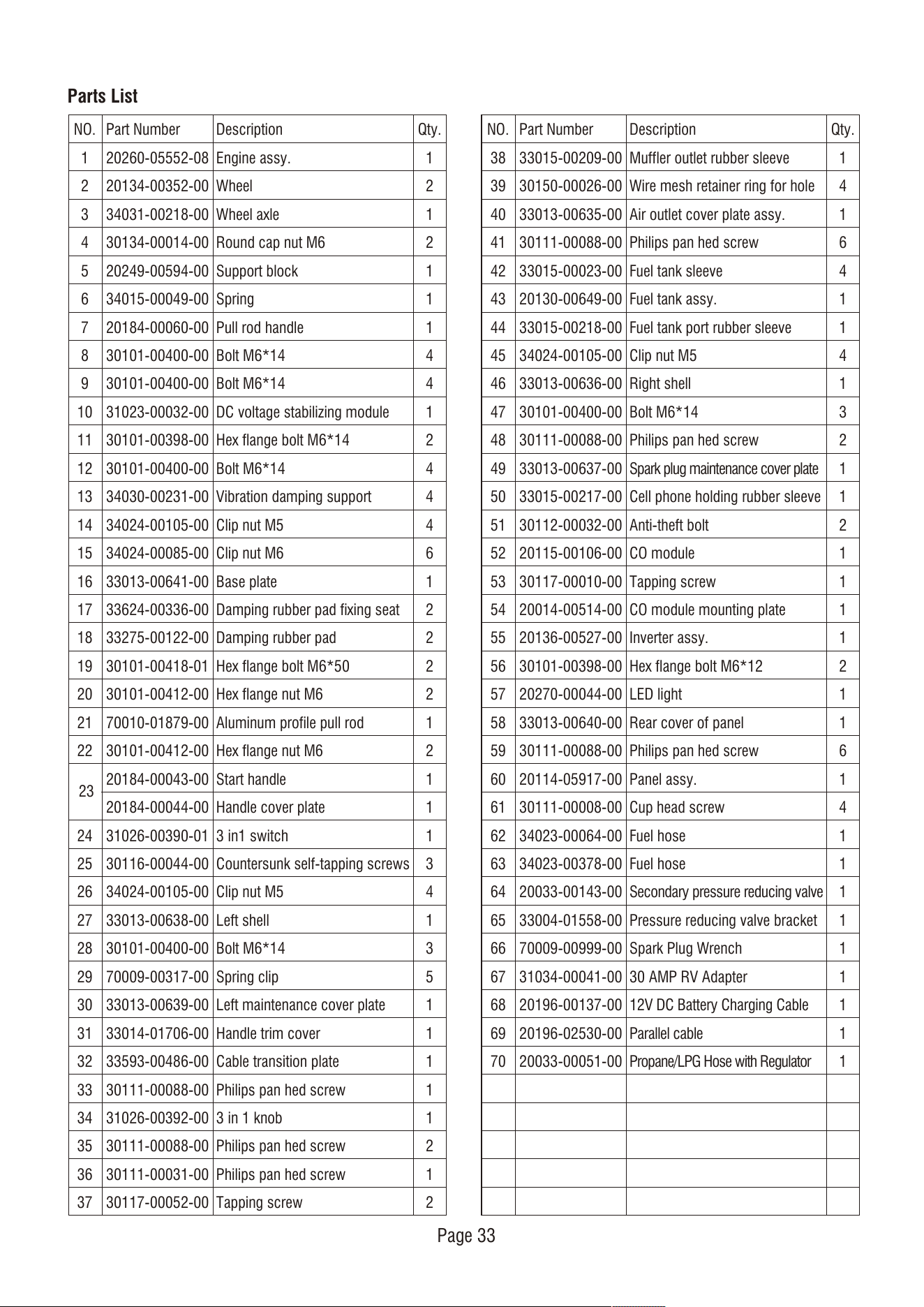
Parts List
NO.
1
2
3
4
5
6
7
8
9
10
11
12
13
14
15
16
17
18
19
20
21
22
24
25
26
27
28
29
30
31
32
33
34
35
36
37
Qty.
1
2
1
2
1
1
1
4
4
1
2
4
4
4
6
1
2
2
2
2
1
2
1
1
1
3
4
1
3
5
1
1
1
1
1
2
1
2
Part Number
20260-05552-08
20134-00352-00
34031-00218-00
30134-00014-00
20249-00594-00
34015-00049-00
20184-00060-00
30101-00400-00
30101-00400-00
31023-00032-00
30101-00398-00
30101-00400-00
34030-00231-00
34024-00105-00
34024-00085-00
33013-00641-00
33624-00336-00
33275-00122-00
30101-00418-01
30101-00412-00
70010-01879-00
30101-00412-00
20184-00043-00
20184-00044-00
31026-00390-01
30116-00044-00
34024-00105-00
33013-00638-00
30101-00400-00
70009-00317-00
33013-00639-00
33014-01706-00
33593-00486-00
30111-00088-00
31026-00392-00
30111-00088-00
30111-00031-00
30117-00052-00
Description
Engine assy.
Wheel
Wheel axle
Round cap nut M6
Support block
Spring
Pull rod handle
Bolt M6*14
Bolt M6*14
DC voltage stabilizing module
Hex flange bolt M6*14
Bolt M6*14
Vibration damping support
Clip nut M5
Clip nut M6
Base plate
Damping rubber pad fixing seat
Damping rubber pad
Hex flange bolt M6*50
Hex flange nut M6
Aluminum profile pull rod
Hex flange nut M6
Start handle
Handle cover plate
3 in1 switch
Countersunk self-tapping screws
Clip nut M5
Left shell
Bolt M6*14
Spring clip
Left maintenance cover plate
Handle trim cover
Cable transition plate
Philips pan hed screw
3 in 1 knob
Philips pan hed screw
Philips pan hed screw
Tapping screw
NO.
38
39
40
41
42
43
44
45
46
47
48
49
50
51
52
53
54
55
56
57
58
59
60
61
62
63
64
65
66
67
68
69
70
Qty.
1
4
1
6
4
1
1
4
1
3
2
1
1
2
1
1
1
1
2
1
1
6
1
4
1
1
1
1
1
1
1
1
1
Part Number
33015-00209-00
30150-00026-00
33013-00635-00
30111-00088-00
33015-00023-00
20130-00649-00
33015-00218-00
34024-00105-00
33013-00636-00
30101-00400-00
30111-00088-00
33013-00637-00
33015-00217-00
30112-00032-00
20115-00106-00
30117-00010-00
20014-00514-00
20136-00527-00
30101-00398-00
20270-00044-00
33013-00640-00
30111-00088-00
20114-05917-00
30111-00008-00
34023-00064-00
34023-00378-00
20033-00143-00
33004-01558-00
70009-00999-00
31034-00041-00
20196-00137-00
20196-02530-00
20033-00051-00
Description
Muffler outlet rubber sleeve
Wire mesh retainer ring for hole
Air outlet cover plate assy.
Philips pan hed screw
Fuel tank sleeve
Fuel tank assy.
Fuel tank port rubber sleeve
Clip nut M5
Right shell
Bolt M6*14
Philips pan hed screw
Spark plug maintenance cover plate
Cell phone holding rubber sleeve
Anti-theft bolt
CO module
Tapping screw
CO module mounting plate
Inverter assy.
Hex flange bolt M6*12
LED light
Rear cover of panel
Philips pan hed screw
Panel assy.
Cup head screw
Fuel hose
Fuel hose
Secondary pressure reducing valve
Pressure reducing valve bracket
Spark Plug Wrench
30 AMP RV Adapter
12V DC Battery Charging Cable
Parallel cable
Propane/LPG Hose with Regulator
23
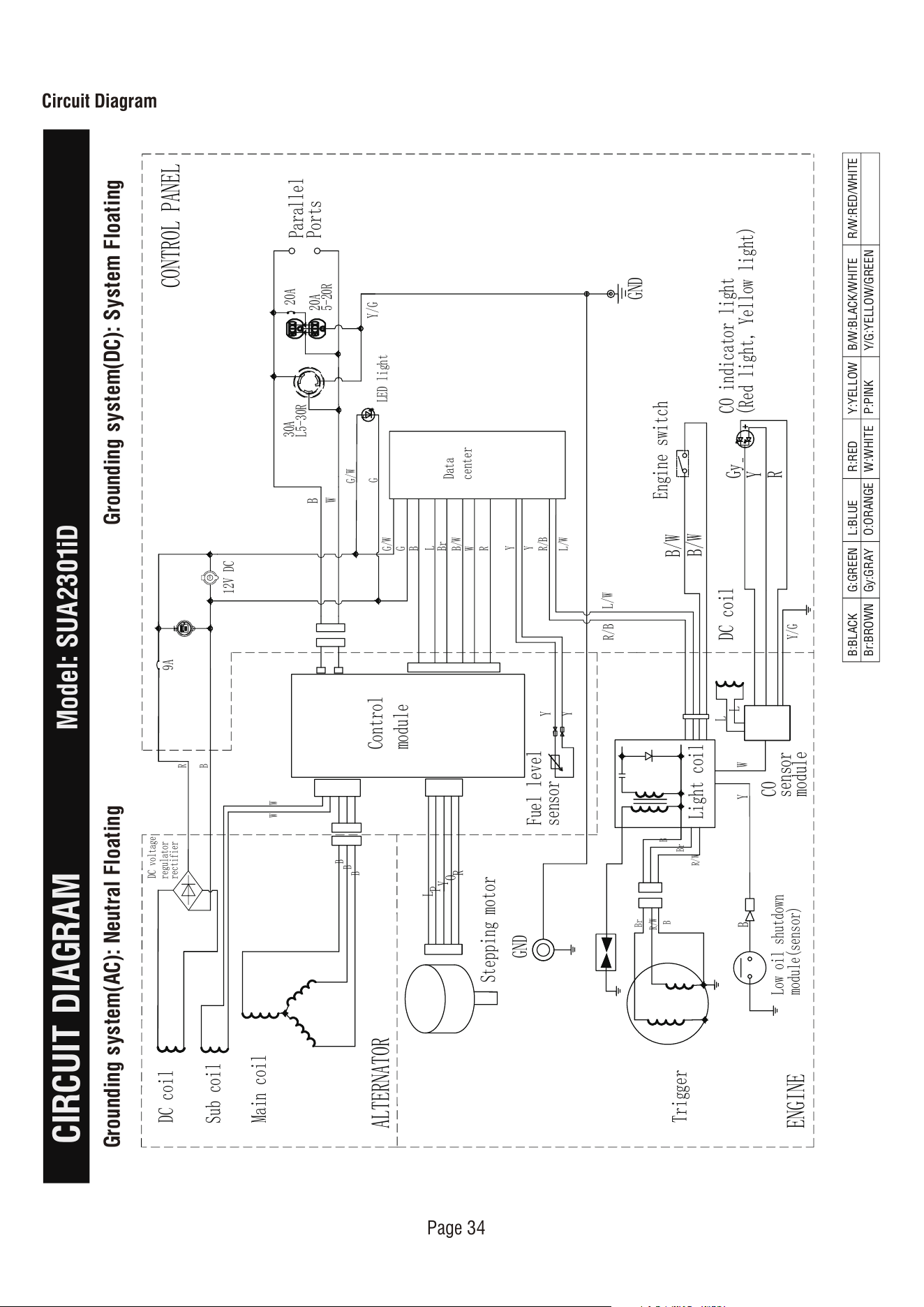
+
-
+
9A
Sub coil
DC coil
R/B
L/W
G
B
B
W W
Control
module
B
R
CONTROL PANEL
B
L
Br
B/W
Data
center
G/W
G
G/W
W
R
Y
Y
R/B
L/W
B
W
Y/G
LED light
DC voltage
regulator
rectifier
Parallel
Ports
20A
L5-30R
30A
5-20R
20A
ALTERNATOR
Y
Y
Fuel level
sensor
Stepping motor
L
P
Y
O
R
Main coil
B
GND
Br
R/W
B
B
Trigger
ENGINE
B
Br
R/W
Light coil
L
L
GND
Engine switch
Y
Low oil shutdown
module(sensor)
CO indicator light
(Red light, Yellow light)
Gy
Y
R
DC coil
Y/G
W
B/W
B/W
CO
sensor
module
Page 34
Circuit Diagram
CIRCUIT DIAGRAM
Model: SUA2301iD
B:BLACK
Br:BROWN
G:GREEN
Gy:GRAY
L:BLUE
O:ORANGE
R:RED
W:WHITE
Y:YELLOW
P:PINK
B/W:BLACK/WHITE
Y/G:YELLOW/GREEN
R/W:RED/WHITE
Grounding system(AC): Neutral Floating Grounding system(DC): System Floating
12V
12V DC
Page 35
WARRANTY
LIMITED WARRANTY
WARRANTY
Warranty Term
KEEP YOUR RECEIPT. Proof of purchase will be
required to substantiate any warranty claim.
WHAT IS COVERED: A-iPower Corp. warrants to the
original retail purchaser in the United States of
America, or Canada that this product is free of
defects in material and workmanship and agrees, at
A-iPower Corp’s direction, to either repair, provide
replacement parts for, or replace (without charge for
parts or labor) any product or component with a
material defect for a period of 3 years from the date
of purchase, except as limited below. Warranty
service and replacement parts are warranted only for
the duration of the warranty on the original product.
All replaced parts or products become a property of
A-iPower Corp.
This product is also covered by an Emissions Control
System Warranty which is separate from and in
addition to the warranty.
A-iPower Limited Warranty – 3 Years Residential and
1 Year Commercial
3 years Residential warranty applies as follow: 1st
year Parts & Labor / 2nd & 3rd year Parts ONLY
A-iPower will provide warranty for any of its products
purchased through any authorized AiPower dealer in
North America to the original purchaser and will be
warranted against defects in material or workmanship
for a period of three (3) years for Consumer use from
date of purchase, subject to exclusions noted herein.
Commercial and Rental applications are warranted for
a period of one (1) year from date of purchase.
How to Obtain Warranty Service
DO NOT RETURN THE PRODUCT TO THE PLACE
OF PURCHASE
Please call our Customer Service Dept.
855-888-3598
Please have necessary information available - Model
Number, Serial Number, Proof of Purchase
Warranty Exclusions
This warranty does not cover the following:
Regular wear and maintenance - this warranty will
not cover repair when normal use has exhausted the
lifetime of a part(s) or engine.
Installation and Maintenance - this warranty does not
cover improper or unauthorized assembly, alteration,
modification or any other damage resulting from
misuse or neglect.
Normal maintenance parts - this warranty does not
cover spark plugs, air filters, adjustments, or other
related service due to obstructions and other build
ups resulting from improper maintenance.
Additional exclusions - this warranty does not cover
wearable parts such as filers, spark plugs, o-rings,
batteries etc. It does not cover any cosmetic defects
such as scratches to paint, decals etc. It does not
cover any damage resulting from use of non-original
manufacturer’s parts, use of aftermarket parts. It
does not cover any failures due to acts of God and
A-iPower Customer Service Dept will assist with all
product related questions and will help troubleshoot
issues and will send any replacement parts as
necessary while product is within the warranty period
at no charge. If the issue cannot be resolved then
A-iPower Customer Service Dept at its discretion
determine and authorize diagnosis and repair through
one of its authorized Service Centers. A-iPower Corp
at its discretion may choose to provide replace of
part, component, or product.
Service or replacement of parts at any unauthorized
repair facility without prior authorization will not be
covered by this warranty.
“Consumer Use” - residential household use by a
retail consumer
“Commercial Use” - all other use - commercial ,
business, industrial, or rental purpose
Thank you for choosing A-iPower products. To
ensure proper registration of your product warranty,
please submit your warranty registration along with
proof of purchase within 10 days of the date of
purchase, this can be done by
a) Completing the Warranty Registration form at the
back of this manual and mailing to:
A-IPOWER CORP
10887 COMMERCE WAY UNIT A
FONTANA CA 92337 USA
b) Visit us at www.a-ipower.com and click the
product registration icon
Page 36
other force majeure events beyond the control of the
manufacturer.
Warranty limits and Implications and
Consequential Damages
A-iPower is not obligated to cover any loss of time,
use of product, freight cost, or any other incidental
or consequential claim from the use of this product.
This warranty is in Lieu of all other warranties,
express or implied.
This warranty gives you specific legal rights which
vary from state to state.
MERCHANDISE RETURN GUIDELINES
• All products must be returned in original or
equivalent packaging. Improperly packaged returns
will not be accepted.
• Must have adequate packing for transportation.
• Federal Law requires that all machines that utilize
gasoline, oil, or other flammable liquids must be
drained Completely & Thoroughly prior to shipment.
• Gas caps and oil plugs must be left off for 24
hours prior to shipping. Please note: liability for this
violation of the law resides with the sender of the
shipment.
• Return to address provided in return authorization,
using the parcel service required. Units returned
without authorization will not be honored.
• Please Note: Refunds will not be granted for items
that have been modified or damaged by abuse or
usage not in accordance with product instructions.
WARRANTY

Fontana, CA 92337 USA
Phone: 855-888-3598
support@a-ipower.com
www.a-ipower.com
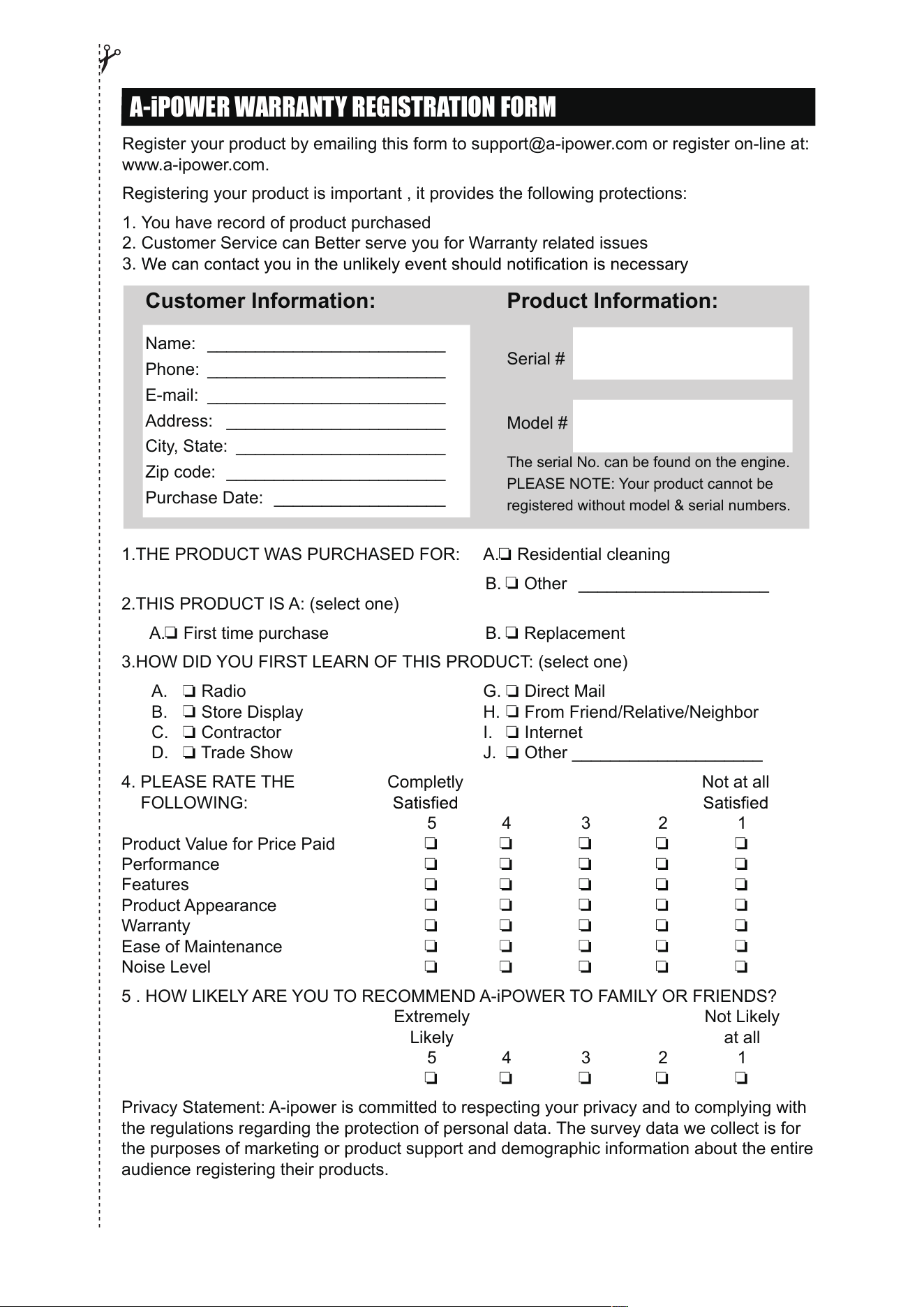
A-iPOWER WARRANTY REGISTRATION FORM
Register your product by emailing this form to support@a-ipower.com or register on-line at:
www.a-ipower.com.
Registering your product is important , it provides the following protections:
1. You have record of product purchased
2. Customer Service can Better serve you for Warranty related issues
3.
1.THE PRODUCT WAS PURCHASED FOR: A. Residential cleaning
B. Other ____________________
2.THIS PRODUCT IS A: (select one)
A. First time purchase B. Replacement
3.HOW DID YOU FIRST LEARN OF THIS PRODUCT: (select one)
A. Radio G. Direct Mail
B. Store Display H. From Friend/Relative/Neighbor
C. Contractor I. Internet
D. Trade Show J. Other ____________________
4. PLEASE RATE THE Completly Not at all
FOLLOWING:
5 4 3 2 1
Product Value for Price Paid
Performance
Features
Product Appearance
Warranty
Ease of Maintenance
Noise Level
5 . HOW LIKELY ARE YOU TO RECOMMEND A-iPOWER TO FAMILY OR FRIENDS?
Extremely Not Likely
Likely at all
5 4 3 2 1
Privacy Statement: A-ipower is committed to respecting your privacy and to complying with
the regulations regarding the protection of personal data. The survey data we collect is for
the purposes of marketing or product support and demographic information about the entire
audience registering their products.
Customer Information:
Name: _________________________
Phone: _________________________
E-mail: _________________________
Address: _______________________
City, State: ______________________
Zip code: _______________________
Purchase Date: __________________
Product Information:
Serial #
Model #
The serial No. can be found on the engine.
PLEASE NOTE: Your product cannot be
registered without model & serial numbers.

Fontana, CA 92337 USA
Phone: 855-888-3598
support@a-ipower.com
www.a-ipower.com