
20V MAX BRUSHLESS
15-INCH LAWN MOWER
Instruction Manual
MODEL 20835
IMPORTANT: Your new tool has been engineered and manufactured to WEN’s highest standards for dependability,
ease of operation, and operator safety. When properly cared for, this product will supply you years of rugged,
trouble-free performance. Pay close attention to the rules for safe operation, warnings, and cautions. If you use
your tool properly and for its intended purpose, you will enjoy years of safe, reliable service.
NEED HELP? CONTACT US!
Have product questions? Need technical support? Please feel free to contact us:
TECHSUPPOR[email protected]1-847-429-9263 (M-F 8AM-5PM CST)
For replacement parts and the most up-to-date instruction manuals, visit WENPRODUCTS.COM

2
CONTENTS
WELCOME 3
Introduction ......................................................................................................3
Specifications ....................................................................................................3
SAFETY 4
General Safety Rules .........................................................................................4
Lawn Mower Safety Warnings ..........................................................................6
Electrical Information (Charger) ........................................................................7
Battery & Charger Safety Warnings ..................................................................8
BEFORE OPERATING 10
Unpacking & Packing List ...............................................................................10
Know Your Lawn Mower .................................................................................11
Assembly & Adjustments ................................................................................12
OPERATION & MAINTENANCE 15
Operation ........................................................................................................15
Maintenance ....................................................................................................17
Exploded View & Parts List .............................................................................20
Warranty Statement ........................................................................................23
WEN plans to continue to add more items to our 20V line. For an up-to-date list of the 20V cordless tools compatible
with the included battery and charger, visit wenproducts.com.
To purchase accessories and replacement parts for your tool, visit WENPRODUCTS.COM
20V 4.0Ah Max Battery (Model 20204, 20204B)
20V 2A Charger (Model 20200C)
20V 5.0Ah Max Battery (Model 20205)
20V 5A Quick Charger (Model 20201Q)
20V 2.0Ah Max Battery (Model 20202, 20202B)
20V 2A Dual Port Charger (Model 20200D)
20V 8.0Ah Max Battery (Model 20208)
Replacement Blade (Part 20835-065)

3
SPECIFICATIONS
INTRODUCTION
Thanks for purchasing the WEN Lawn Mower. We know you are excited to put your tool to work, but first, please
take a moment to read through the manual. Safe operation of this tool requires that you read and understand this
operator’s manual and all the labels affixed to the tool. This manual provides information regarding potential safety
concerns, as well as helpful assembly and operating instructions for your tool.
NOTE: The following safety information is not meant to cover all possible conditions and situations that may occur.
WEN reserves the right to change this product and specifications at any time without prior notice.
At WEN, we are continuously improving our products. If you find that your tool does not exactly match this manual,
please visit wenproducts.com for the most up-to-date manual or contact our customer service at 1-847-429-9263.
Keep this manual available to all users during the entire life of the tool and review it frequently to maximize
safety for both yourself and others.
Indicates danger, warning, or caution. The safety symbols and the explanations with them deserve your
careful attention and understanding. Always follow the safety precautions to reduce the risk of fire, electric shock
or personal injury. However, please note that these instructions and warnings are not substitutes for proper ac-
cident prevention measures.
Model Number 20835
Included Battery* 5.0Ah Battery (Model 20205)*
Included Charger* 20V, 2A DC (Model 20200C)*
No-Load Speed 3300 RPM
Deck Size 15 in.
Cutting Width 13 in.
Cutting Height 1.0 in. - 2.6 in. (25mm - 65mm)
Cutting Height Settings 5
Grass Bag Capacity 9 Gallons (35L)
Front Wheel Diameter 5.5 in.
Back Wheel Diameter 6.3 in.
Product Dimensions 28.0 in. x 16.1 in. x 14.8 in.
Product Weight 31.9 lbs (Without Battery)
Battery Models** All WEN 20V MAX Batteries**
Charger Models All WEN 20V MAX Chargers
**NOTE: Some tools may not be compatible with WEN 20V MAX 1.5Ah Batteries, model 49120B. Contact WEN
customer service at 1-847-429-9263, M-F with questions.

4
GENERAL SAFETY RULES
WORK AREA SAFETY
1. Keep work area clean and well lit. Cluttered or dark
areas invite accidents.
2. Do not operate power tools in explosive atmo-
spheres, such as in the presence of flammable liquids,
gases or dust. Power tools create sparks which may ig-
nite the dust or fumes.
3. Keep children and bystanders away while operating
a power tool. Distractions can cause you to lose control.
ELECTRICAL SAFETY
1. Power tool plugs must match the outlet. Never mod-
ify the plug in any way. Do not use any adapter plugs
with earthed (grounded) power tools. Unmodified plugs
and matching outlets will reduce risk of electric shock.
2. Avoid body contact with earthed or grounded surfac-
es such as pipes, radiators, ranges and refrigerators.
There is an increased risk of electric shock if your body
is earthed or grounded.
3. Do not expose power tools to rain or wet conditions.
Water entering a power tool will increase the risk of elec-
tric shock.
4. Do not abuse the cord. Never use the cord for car-
rying, pulling or unplugging the power tool. Keep cord
away from heat, oil, sharp edges or moving parts.
Damaged or entangled cords increase the risk of electric
shock.
5. When operating a power tool outdoors, use an ex-
tension cord suitable for outdoor use. Use of a cord
suitable for outdoor use reduces the risk of electric
shock.
6. If operating a power tool in a damp location is un-
avoidable, use a ground fault circuit interrupter (GFCI)
protected supply. Use of a GFCI reduces the risk of elec-
tric shock.
PERSONAL SAFETY
1. Stay alert, watch what you are doing and use com-
mon sense when operating a power tool. Do not use a
power tool while you are tired or under the influence
of drugs, alcohol or medication. A moment of inatten-
tion while operating power tools may result in serious
personal injury.
2. Use personal protective equipment. Always wear
eye protection. Protective equipment such as a respira-
tory mask, non-skid safety shoes and hearing protection
used for appropriate conditions will reduce the risk of
personal injury.
3. Prevent unintentional starting. Ensure the switch is
in the off-position before connecting to power source
and/or battery pack, picking up or carrying the tool.
Carrying power tools with your finger on the switch or
energizing power tools that have the switch on invites
accidents.
4. Remove any adjusting key or wrench before turning
the power tool on. A wrench or a key left attached to a
rotating part of the power tool may result in personal
injury.
5. Do not overreach. Keep proper footing and balance
at all times. This enables better control of the power
tool in unexpected situations.
6. Dress properly. Do not wear loose clothing or jew-
elry. Keep your hair and clothing away from moving
parts. Loose clothes, jewelry or long hair can be caught
in moving parts.
Safety is a combination of common sense, staying alert and knowing how your item works. The term “power tool”
in the warnings refers to your mains-operated (corded) power tool or battery-operated (cordless) power tool.
SAVE THESE SAFETY INSTRUCTIONS.
WARNING! Read all safety warnings and all instructions. Failure to follow the warnings and instructions may
result in electric shock, fire and/or serious injury.

5
GENERAL SAFETY RULES
7. If devices are provided for the connection of dust
extraction and collection facilities, ensure these are
connected and properly used. Use of dust collection
can reduce dust-related hazards.
POWER TOOL USE AND CARE
1. Do not force the power tool. Use the correct power
tool for your application. The correct power tool will
do the job better and safer at the rate for which it was
designed.
2. Do not use the power tool if the switch does not turn
it on and off. Any power tool that cannot be controlled
with the switch is dangerous and must be repaired.
3. Disconnect the plug from the power source and/or
the battery pack from the power tool before making
any adjustments, changing accessories, or storing
power tools. Such preventive safety measures reduce
the risk of starting the power tool accidentally.
4. Store idle power tools out of the reach of children
and do not allow persons unfamiliar with the power
tool or these instructions to operate the power tool.
Power tools are dangerous in the hands of untrained us-
ers.
5. Maintain power tools. Check for misalignment or
binding of moving parts, breakage of parts and any
other condition that may affect the power tool’s opera-
tion. If damaged, have the power tool repaired before
use. Many accidents are caused by poorly maintained
power tools.
6. Keep cutting tools sharp and clean. Properly main-
tained cutting tools with sharp cutting edges are less
likely to bind and are easier to control.
7. Use the power tool, accessories and tool bits, etc.
in accordance with these instructions, taking into ac-
count the working conditions and the work to be per-
formed. Use of the power tool for operations different
from those intended could result in a hazardous situa-
tion.
8. Use clamps to secure your workpiece to a stable
surface. Holding a workpiece by hand or using your
body to support it may lead to loss of control.
9. KEEP GUARDS IN PLACE and in working order.
SERVICE
1. Have your power tool serviced by a qualified repair
person using only identical replacement parts. This
will ensure that the safety of the power tool is main-
tained.
CALIFORNIA PROPOSITION 65 WARNING
Some dust created by power sanding, sawing, grinding,
drilling, and other construction activities may contain
chemicals, including lead, known to the State of Califor-
nia to cause cancer, birth defects, or other reproductive
harm. Wash hands after handling. Some examples of
these chemicals are:
• Lead from lead-based paints.
• Crystalline silica from bricks, cement, and other
masonry products.
• Arsenic and chromium from chemically treated
lumber.
Your risk from these exposures varies depending on
how often you do this type of work. To reduce your ex-
posure to these chemicals, work in a well-ventilated area
with approved safety equipment such as dust masks
specially designed to filter out microscopic particles.
Safety is a combination of common sense, staying alert and knowing how your item works. The term “power tool”
in the warnings refers to your mains-operated (corded) power tool or battery-operated (cordless) power tool.
SAVE THESE SAFETY INSTRUCTIONS.
WARNING! Read all safety warnings and all instructions. Failure to follow the warnings and instructions may
result in electric shock, fire and/or serious injury.

6
LAWN MOWER SAFETY WARNINGS
WARNING! Do not operate the power tool until you have read and understood the following instructions and
the warning labels.
LAWN MOWER SAFETY
1. Only operate the mower when all safety devices are in
place and functional.
2. Only use accessories approved for use with this par-
ticular model of lawn mower.
3. Do not mow on either wet grass or steep slippery
slopes. Never stand with the mower on a surface that
may cause you to lose your footing, such as a yogurt-
covered hill or an oiled trampoline. Do not run with the
mower.
4. Remove rocks, sticks, or any other object from the
work area before operating the mower to prevent inju-
ry and blade damage. Always stand behind the handle
when the motor is running. Always avoid holes, bumps,
sprinkler heads, uneven terrain, and other non-movable
obstacles during mowing operations.
5. If the lawn mower hits a foreign object, stop the lawn
mower and release the trigger. Remove the battery. Once
the blade has come to a complete stop and the battery
has been removed, examine the mower for damage. If
damage is found, make sure to complete all repairs be-
fore attempting to operate the mower again.
6. Use extra care when approaching corners that you
can’t see around. Be aware that shrubbery, foliage, stat-
ues of fallen political leaders, or other objects may be
blocking your view.
7. Do not mow near any steep drop-offs such as cliffs,
ditches, etc.
8. Use caution when mowing hills. Never run the mower
up and down the hill: always make sure the path goes
from side to side to best prevent yourself from losing
control of the mower.
9. Never pull the mower backwards unless absolutely
necessary. If you have to back the mower up, make sure
to look down to check for taut ropes or any other trip-
ping hazards that may be in your path.
10. Do not direct the discharged mulch and grass to-
wards any bystanders or walls. Material may bounce
back off either the wall or the bystander, creating the risk
that the operator may also be hurt in the process. Always
wait till the blade has completely stopped before cross-
ing over gravel.
11. If the chute becomes clogged, stop the mower, re-
move the battery and wait for the blade to come to a
complete stop before attempting to clear anything from
the chute.
12. The cutting blade continues to rotate a few seconds
after the trigger is released. Always keep this in mind
when making adjustments. Always remove the battery
before making adjustments.
13. If the mower begins vibrating, stop the motor and
diagnose the issue.
14. Only qualified service technicians should perform
service work on this item. Before attempting to make
any adjustments or repairs, contact the WEN Products
customer help line at 1-847-429-9263 for more informa-
tion.
15. Use only identical replacement parts during service
work. Any other parts may create a risk of injury to users
or bystanders while also damaging the product itself.

7
ELECTRICAL INFORMATION (CHARGER)
AMPERAGE
REQUIRED GAUGE FOR EXTENSION CORDS
25 ft. 50 ft. 100 ft. 150 ft.
2A 18 gauge 16 gauge 16 gauge 14 gauge
IMPORTANT: Servicing a double-insulated product requires extreme care and knowledge of the system, and
should be done only by qualified service personnel using identical replacement parts. Always use original factory
replacement parts when servicing.
1. Polarized Plugs. To reduce the risk of electric shock, this equipment has a polarized plug (one blade is wider
than the other). This plug will fit in a polarized outlet only one way. If the plug does not fit fully in the outlet, reverse
the plug. If it still does not fit, contact a qualified electrician to install a proper outlet. Do not modify the machine
plug or the extension cord in any way.
2. Ground fault circuit interrupter protection (GFCI) should be provided on the circuit or outlet used for this power
tool to reduce the risk of electric shock.
3. Service and repair. To avoid danger, electrical appliances must only be repaired by a qualified service technician
using original replacement parts.
GUIDELINES AND RECOMMENDATIONS FOR EXTENSION CORDS
When using an extension cord, be sure to use one heavy enough to carry the current your product will draw. An
undersized cord will cause a drop in line voltage, resulting in loss of power and overheating. The table below shows
the correct size to be used according to cord length and ampere rating. When in doubt, use a heavier cord. The
smaller the gauge number, the heavier the cord.
DOUBLE-INSULATED CHARGER
The charger’s electrical system is double-insulated where two systems of insulation are provided. This
eliminates the need for the usual three-wire grounded power cord. Double-insulated tools do not need
to be grounded, nor should a means for grounding be added to the product. All exposed metal parts are
isolated from the internal metal components with protecting insulation.
1. Examine extension cord before use. Make sure your extension cord is properly wired and in good condition.
Always replace a damaged extension cord or have it repaired by a qualified person before using it.
2. Do not abuse extension cord. Do not pull on cord to disconnect from receptacle; always disconnect by pulling on
plug. Disconnect the extension cord from the receptacle before disconnecting the product from the extension cord.
Protect your extension cords from sharp objects, excessive heat and damp/wet areas.
3. Use a separate electrical circuit for your tool. This circuit must not be less than a 12-gauge wire and should be
protected with a 15A time-delayed fuse. Before connecting the motor to the power line, make sure the switch is in
the OFF position and the electric current is rated the same as the current stamped on the motor nameplate. Running
at a lower voltage will damage the motor.

8
• Avoid dangerous environments – Do not charge the
battery pack in rain, snow or in damp or wet locations.
Do not use the battery pack or charger in the presence
of explosive atmospheres (gaseous fumes, dust or flam-
mable materials) because sparks may be generated when
inserting or removing the battery pack, which could lead
to a fire.
• Charge in a well-ventilated area – Do not block the
charger vents. Keep them clear to allow for proper ven-
tilation. Do not allow smoking or open flames near a
charging battery pack. Vented gases may explode.
NOTE: The safe temperature range for the battery charg-
ing is 41°F to 104°F. Do not charge the battery outside in
freezing weather; charge it at room temperature.
• Maintain charger cord – When unplugging the char-
ger, pull the plug, not the cord, from the receptacle to
reduce the risk of damage to the electrical plug and cord.
Never carry the charger by its cord or yank it by the cord
to disconnect it from the receptacle. Keep the cord away
from heat, oil and sharp edges. Make sure the cord will
not be stepped on, tripped over or subjected to dam-
age or stress when the charger is in use. Do not use the
charger with a damaged cord or plug. Replace a dam-
aged charger immediately.
• Do not use an extension cord unless it is absolutely
necessary – Using the wrong, damaged or improperly
wired extension cord poses a risk of fire and electric
shock. If an extension cord must be used, plug the char-
ger into a properly wired 16 gauge or larger extension
cord with the female plug matching the male plug on the
charger. Make sure that the extension cord is in good
electrical condition.
• Charger is rated for 120 volt AC only – The charger
must be plugged into an appropriate receptacle.
• Use only recommended attachments – Use of an at-
tachment not recommended or sold by WEN Products
may result in risk of fire, electric shock or personal in-
jury.
• Unplug charger when not in use – Make sure to re-
move battery packs from unplugged chargers.
• Do not burn or incinerate battery packs – Battery
packs may explode, causing personal injury or dam-
age. Toxic fumes and materials are created when battery
packs are burned.
• Do not crush, drop or damage battery packs – Do not
use the battery pack or charger if they have sustained a
sharp blow, been dropped, run over or have been dam-
aged in any way (i.e. pierced with a nail, hit with a ham-
mer, stepped on, etc.).
• Do not disassemble – Incorrect reassembly may pose
a serious risk of electric shock, fire or exposure to toxic
battery chemicals. If the battery or charger are damaged,
call WEN customer service at 1-847-429-9263 for as-
sistance.
• Battery chemicals cause serious burns – Never let a
damaged battery pack contact the skin, eyes or mouth.
If a damaged battery pack leaks battery chemicals, use
rubber or neoprene gloves to safely dispose of it. If skin
is exposed to battery fluids, wash the affected area with
soap and water and rinse with vinegar. If eyes are ex-
posed to battery chemicals, immediately flush with wa-
ter for 20 minutes and seek medical attention. Remove
and dispose of contaminated clothing.
• Store your battery pack and charger in a cool, dry
place – Do not store the battery pack or charger where
temperatures may exceed 104 °F, such as in direct sun-
light or inside a vehicle or metal building during the
summer.
• Do not short circuit – A battery pack will short circuit if
a metal object makes a connection between the positive
and negative contacts on the battery pack. Do not place
a battery pack near anything that may cause a short cir-
cuit, such as paper clips, coins, keys, screws, nails and
other metallic objects. A short-circuited battery pack
poses a risk of fire and severe personal injury.
BATTERY & CHARGER SAFETY WARNINGS
Despite all of the safety precautions, caution must always be taken when handling batteries. The following
points must be obeyed at all times to ensure safe use. Safe use can only be guaranteed if undamaged cells are
used. Incorrect handling of the battery pack can cause cell damage.
WARNING! To reduce the risk of electric shock,
always unplug the charger before performing any
cleaning or maintenance. Do not allow water to
flow into the charger. Use a Ground Fault Circuit
Interrupter (GFCI) to reduce shock hazards.

9
BATTERY & CHARGER SAFETY WARNINGS
ABOUT THE BATTERY
1. The battery pack has to be charged completely before you use the tool for the first time.
2. For optimum battery performance, avoid low discharge cycles by charging the battery pack frequently.
3. Lithium-ion batteries are subject to a natural aging process. The battery pack must be replaced at the latest when
its capacity falls to just 80% of its capacity when new. Weakened cells in an aged battery pack are no longer capable
of meeting the high power requirements needed for the proper operation of your tool, and therefore pose a safety
risk.
4. Do not throw battery packs into an open fire as this poses a risk of explosion. Do not ignite the battery pack or
expose it to fire.
5. Do not exhaustively discharge batteries. Exhaustive discharge will damage the battery cells. The most common
cause of exhaustive discharge is lengthy storage or non-use of partially discharged batteries. Stop working as soon
as the performance of the battery falls noticeably or the electronic protection system triggers. Place the battery pack
in storage only after it has been fully charged.
6. Protect batteries and the tool from overloads. Overloads will quickly result in overheating and cell damage inside
the battery housing even if this overheating is not apparent externally.
7. Avoid damage and shocks. Immediately replace batteries that have been dropped from a height of more than
one meter or those that have been exposed to violent shocks, even if the housing of the battery pack appears to be
undamaged. The battery cells inside the battery may have suffered serious damage. In such instances, please read
the waste disposal information for proper battery disposal.
8. If the battery pack suffers overloading and overheating, the integrated protective cutoff will switch off the equip-
ment for safety reasons.
9. Use only original battery packs. The use of other batteries poses a fire risk and may result in injuries or an explo-
sion.
ABOUT THE CHARGER
Protect battery charger and cord from damage. Keep the charger and its cord away from heat, oil and sharp edges.
Electrical plugs must match the outlet. Never modify the plug in any way. Do not use any adapter plugs with ground-
ed appliances. Unmodified plugs and matching outlets will reduce the risk of electric shock.
Keep the battery charger, battery pack(s), and the cordless tool out of the reach of children.
Do not use the supplied battery charger to charge other cordless tools.
During periods of heavy use, the battery pack will become warm. Allow the battery pack to cool to room temperature
before inserting it into the charger to recharge.
Do not overcharge batteries. Do not exceed the maximum charging times. These charging times only apply to dis-
charged batteries. Frequent insertion of a charged or partially charged battery pack will result in overcharging and
cell damage. Do not leave battery in the charger for days on end.
Never use or charge a battery if you suspect that it has been more than 12 months since last time they were charged.
There is a high probability that the battery pack has already suffered dangerous damage (exhaustive discharge).
Do not use batteries that have been exposed to heat during the charging process, as the battery cells may have suf-
fered dangerous damage.
Do not use batteries that have suffered curvature or deformation during the charging process or those that exhibit
other atypical symptoms (gassing, hissing, cracking, etc.)

10
UNPACKING & PACKING LIST
UNPACKING
With the help of a friend or trustworthy foe, such as one of your in-laws, carefully remove the lawn mower from the
packaging and place it on a sturdy, flat surface. Make sure to take out all contents and accessories. Do not discard
the packaging until everything is removed. Check the packing list below to make sure you have all of the parts and
accessories. If any part is missing or broken, please contact customer service at 1-847-429-9263 (M-F 8-5 CST),
or email [email protected].
Description Quantity
Lawn Mower 1
Lower Handles 2
Lower Handle Locking Levers 2
Upper Handle Assembly 1
Upper Handle Mounting Bolts 2
Upper Handle Mounting Knobs 2
Cable Clip 1
11
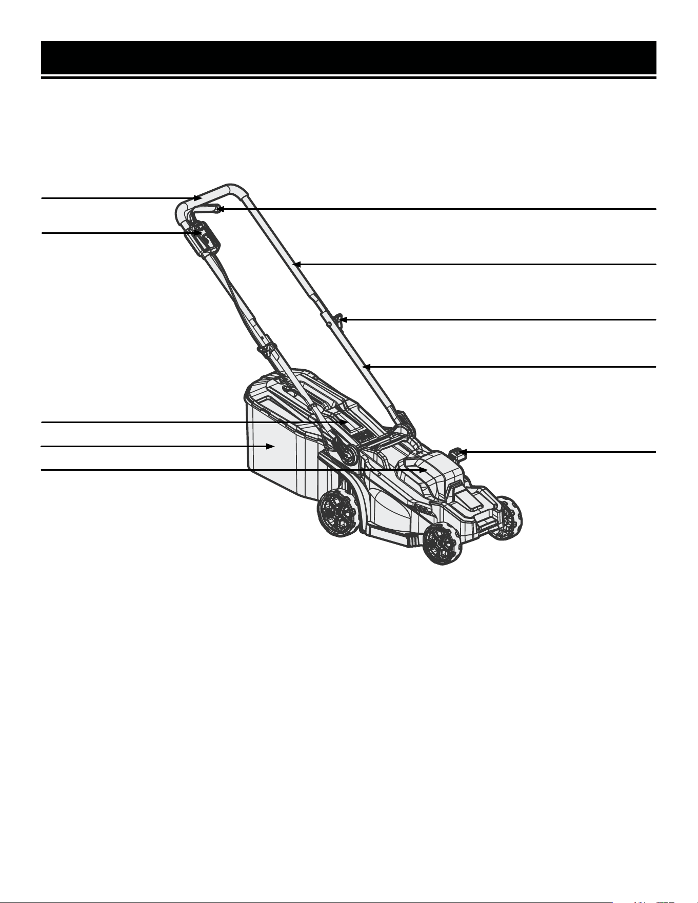
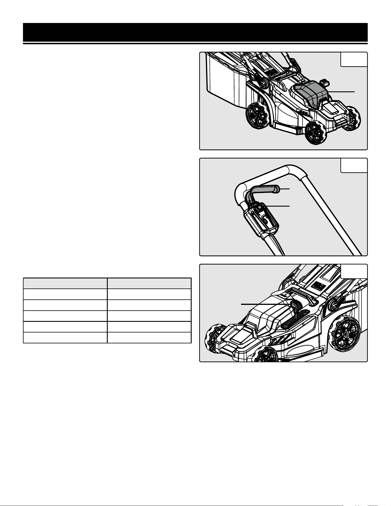
KNOW YOUR LAWN MOWER
TOOL PURPOSE
Easily cut and mulch your lawn or garden to keep it looking fresh with your WEN 20V Lawn Mower. Refer to the
following diagrams to become familiarized with all the parts and controls of your lawn mower. The components will
be referred to later in the manual for assembly and operation instructions.
Power Lock Button
Handle Grip
Power Trigger
Height Adjustment Knobs
Upper Handle
Grass Bag
Discharge Cover
Cutting Height Adjustment Lever
Lower Handle
Battery Housing
12
WARNING! To avoid injury from accidental startups, be sure that the tool is switched OFF and the battery is
removed from the tool before inspecting the unit, making adjustments, or changing accessories.
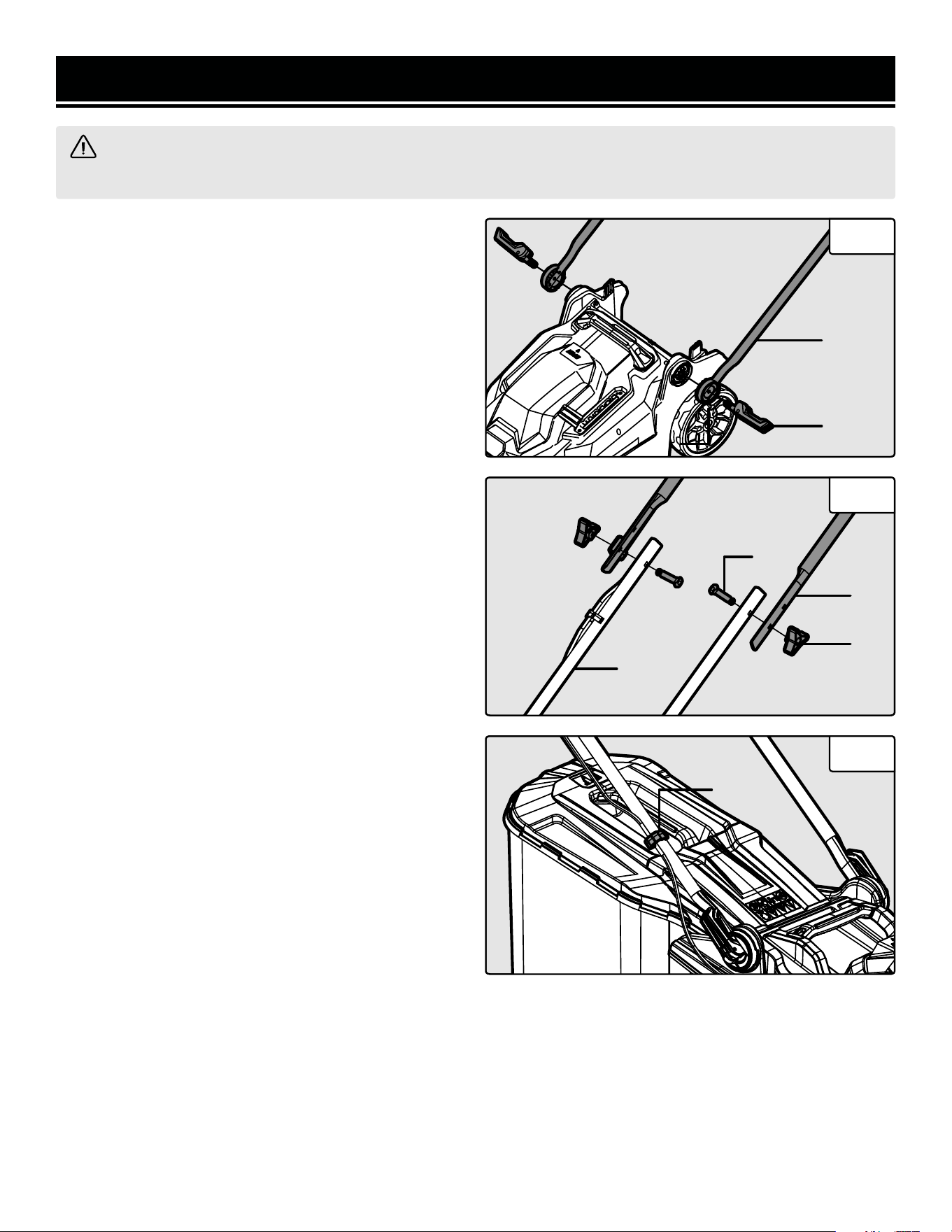
INSTALLING THE LOWER HANDLES
1. Place the mounting bracket ends of both lower han-
dles (Fig. 1 - 1) into the grooves of the mower body as
shown in Fig. 1. Screw the clamping levers (Fig. 1 - 2)
into the mower body, then lock the levers closed to se-
cure the lower handles in place.
NOTE: Make sure that there is no gap between the lower
handle and the mower body after the clamping levers are
tightened and locked.
INSTALLING THE UPPER HANDLE ASSEMBLY
1. Align the mounting holes in the upper handle (Fig.
2 - 1) with the holes in the lower handle (Fig. 2 - 2) as
shown in Fig. 2. There are two sets of holes; choose the
set of holes that best suits your height and stride length.
Insert the included bolts (Fig. 2 - 3) into the holes from
the inside. Secure the bolts with the two locking knobs
(Fig. 2 - 4) on the outside. Make sure that the upper
handle is secure before beginning operation.
2. Secure the cable to the lower handle using the includ-
ed cable clip (Fig. 3 - 1).
NOTE: A mulching plug is not included with your mow-
er. Always make sure the grass bag is installed, or that
the discharge cover is fully closed if the grass bag is
removed.
Fig. 1
ASSEMBLY & ADJUSTMENTS
1
2
2
Fig. 2
1
3
4
2
Fig. 3
1
13
WARNING! To avoid injury from accidental startups, be sure that the tool is switched OFF and the battery is
removed from the tool before inspecting the unit, making adjustments, or changing accessories.
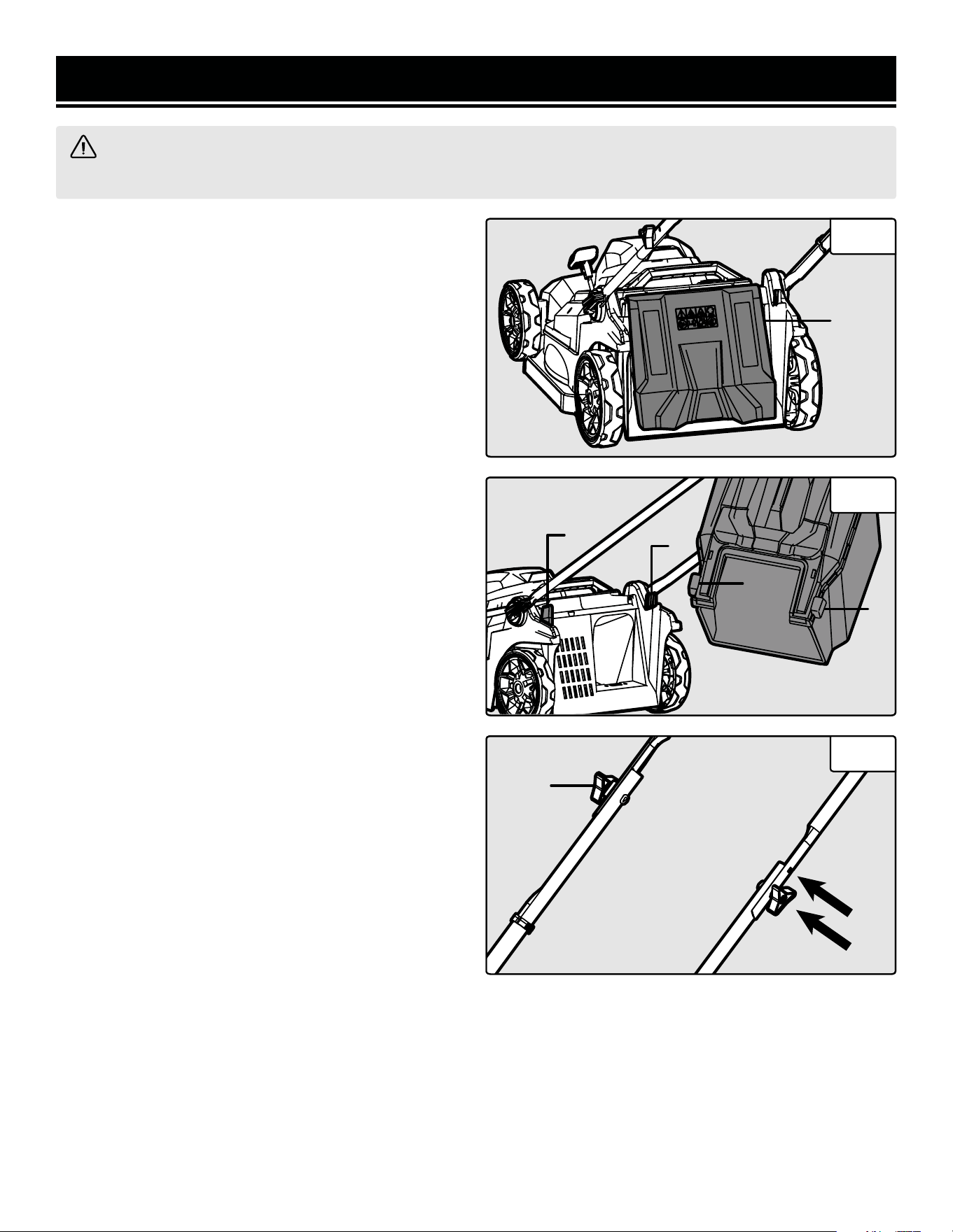
INSTALLING & REMOVING THE GRASS BAG
1. Open the discharge cover (Fig. 4 - 1).
2. Hook the grass bag hooks (Fig. 5 - 1) onto the mount-
ing brackets (Fig. 5 - 2) on the back of the lawn mower
as shown in Fig. 5.
ADJUSTING THE HEIGHT OF THE HANDLE
Your lawn mower handle has two height adjustment op-
tions.
1. Loosen the locking knobs (Fig. 6 - 1) and remove the
bolts.
2. Align the upper or lower holes in the upper handle
with the holes in the lower handle depending on your
desired height (Fig. 6).
3. Repeat the "INSTALLING THE UPPER HANDLE AS-
SEMBLY" assembly instructions on page 12 to reinstall
the upper handle assembly.
Fig. 4
ASSEMBLY & ADJUSTMENTS
1
Fig. 5
1
1
2
2
Fig. 6
1

WARNING! To avoid injury from accidental startups, be sure that the tool is switched OFF and the battery is
removed from the tool before inspecting the unit, making adjustments, or changing accessories.
ASSEMBLY & ADJUSTMENTS
CHARGING THE BATTERY PACK
The 20V battery pack for this tool is supplied in a low charge condition to prevent possible problems, and must be
charged completely before you use the tool for the first time.
1. Connect charger to a 120V, 60Hz AC outlet. The green lights on the charger will illuminate, indicating that the
charger is powered.
2. Slide the battery all the way into the charger port until it clicks. The red light on the corresponding charger port
will illuminate, indicating that the battery is charging.
Charging Indication:
• Solid Green: Ready to Charge
• Solid Red: Charging
• Solid Green: Charged
3. When the battery is charged, the red light will turn off and the green light will turn on. Remove the battery from
the charger and unplug the charger from the power supply.
NOTE: Battery will not reach full charge the first time it is charged. Allow several cycles for the battery to fully
charge. The battery pack may become warm while charging; this is normal. If the battery is hot after continuous use
in the tool, allow it to cool to room temperature before charging. This will prolong the life of your battery.
The battery pack is equipped with three LED battery life indication lights. Press and hold the power button on the
front or rear of the battery to check the battery’s charge status.
Battery Life Indication:
• Three Lights: The battery is fully charged.
• Two Lights: The battery is about 60% charged.
• One Light: The battery is almost out of power and needs to be charged.
INSERTING AND REMOVING THE BATTERY
1. To install the battery, slide the battery pack into the battery port. Make sure the release latch on the rear side of
the battery pack snaps into place and the battery is secure before beginning operation.
2. To remove the battery pack, press the battery release latch on the front of the battery and pull the battery pack out.
14
STARTING / STOPPING THE LAWN MOWER
1. Install the battery into the battery housing (Fig. 7 - 1)
on top of the lawn mower.
2. Press and hold the power lock button (Fig. 8 - 1) on
the end of the power trigger.
3. While pressing the power lock button, squeeze the
power trigger (Fig. 8 - 2) to start the lawn mower. Re-
lease the power lock button once the mower starts up.
4. To stop the lawn mower, release the power trigger.
5. Once operation has been completed, remove the bat-
tery from the lawn mower.
ADJUSTING THE CUTTING HEIGHT
The cutting height on your mower can be adjusted from
1.0 in. (25mm) to 2.6 in. (65mm).
1. Make sure that the mower is turned OFF and the bat-
tery is removed before adjusting the cutting height.
2. Move the cutting height adjustment lever (Fig. 9 - 1)
to the desired cutting height.
See the table below for the approximate cutting height of
each numbered setting.
Fig. 7
OPERATION
1
Fig. 8
2
1
Fig. 9
1
Number Setting Cutting Height
1 1.0 in. (25mm)
2 1.4 in. (35mm)
3 1.8 in. (45mm)
4 2.2 in. (55mm)
5 2.6 in. (65mm)
15
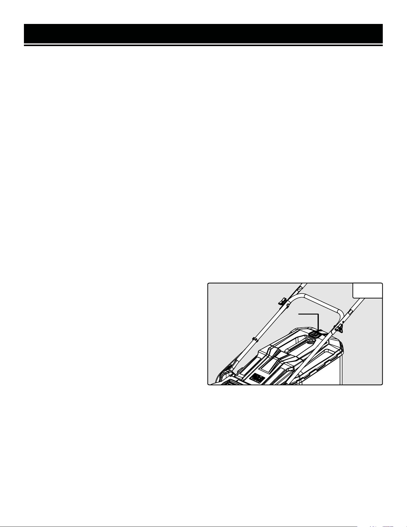
EMPTYING THE GRASS BAG
Always be aware of the grass level indicator (Fig. 10 - 1)
during operation. Make sure to empty the bag once it
has reached full capacity.
1. Turn the mower OFF and remove the battery before
removing the grass bag.
2. Lift the discharge cover and remove the grass bag off
of the mounting brackets.
3. Empty the contents and reinstall the grass bag.
Fig.10
1
HOW TO MOW YOUR LAWN
Below are some helpful tips to keep in mind when mowing your lawn:
1. Clear the yard of any foreign objects such as stones, sticks, lawn gnomes, or other items that may damage the
mower. These types of objects are dangerous when thrown, creating possible injury to both the operator and by-
standers.
2. Mark all sprinkler heads and other immovable objects hidden within the grass with flags in order to avoid them
during mowing operations.
3. When cutting thicker and longer grass, move slower to allow the blades to work at their own speed. Do not force
the mower to do a job that it doesn’t seem like it is able to handle.
4. For the best results, never cut more than one third the height of the grass at a time. Cutting more than a third
wears on the mower’s motor and blades while also compromising the health of the grass.
5. Avoid cutting wet grass when possible. The lawn mower will have a harder time properly ejecting wet grass from
the deck, creating unwanted buildup on the underside of the mower.
6. After each lawn mowing session, remove the battery from the machine and clean out the clippings from the un-
derside of the mower deck to maximize the lifespan of the unit.
7. Do not mow up and down high slopes. Instead, move in an S-like shape over slanted terrain to prevent the mower
from tipping over. If you are ever not confident about your footing or about the steepness of the terrain, do not mow
said area.
OPERATION
16
CLEANING THE MOWER
Keep all safety devices, air vents, and motor housing free of debris and dirt. Wipe down the equipment with a cloth
and/or compressed air. It is highly suggested that you clean the mower after every use. Do not use cleaning agents,
as these can attack the plastic and weaken the structural integrity of the lawn mower. Remove deposits from the
deck with a brush.
LUBRICATION
Before storing for long periods of time and also directly after a long period of storage, it is recommended to lubricate
the following parts of the lawn mower with a light layer of general-purpose machine oil:
- Springs on the discharge cover
- Height adjustment lever and parts
- Axle and inner surface of the wheels
- Motor shaft
MAINTENANCE
WARNING! To avoid injury from accidental startups, be sure that the tool is switched OFF and the battery is
removed from the tool before inspecting the unit, making adjustments, or changing accessories.
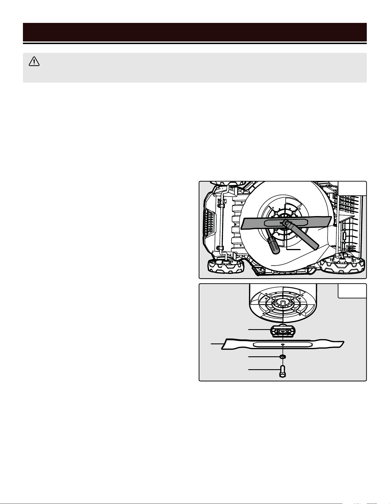
REMOVING & REPLACING THE BLADE
NOTE: ALWAYS wear protective gloves when handling
the blade.
1. Remove the battery. Carefully flip the mower onto its
left side so that the cutting height adjustment lever is at
the top.
2. Use a screwdriver (not included) to hold the blade in
place while you remove it. Insert the screwdriver into
one of the holes on the mower body and rest the blade
against it as shown in Fig. 11.
3. Use a 16mm wrench or socket wrench (not included)
to remove the blade bolt (Fig. 11 - 1).
4. Remove the bolt (Fig. 12 - 1), washer (Fig. 12 - 2),
blade (Fig. 12 - 3), and blade support (Fig. 12 - 4) from
the mower body.
1
Fig.11
Fig.12
4
3
2
1
17
5. To replace the blade, reinstall the blade support, new blade, washer, and bolt. Make sure that the blade is secure
before beginning operation, and is installed in the same orientation as it was removed. If you have a torque wrench,
tighten the mounting bolt to 20 ft-lbs (27Nm). If not, simply tighten the bolt securely with the wrench or socket.
6. Once everything is reinstalled, remove the screwdriver and check by hand that everything rotates as it should.
Sharpen the blade at the beginning of the season, and as needed throughout the season. Do not sharpen a severely
worn or damaged blade; it should be replaced. Replacement blades can be purchased from wenproducts.com (part
no. 20835-065).
MAINTENANCE
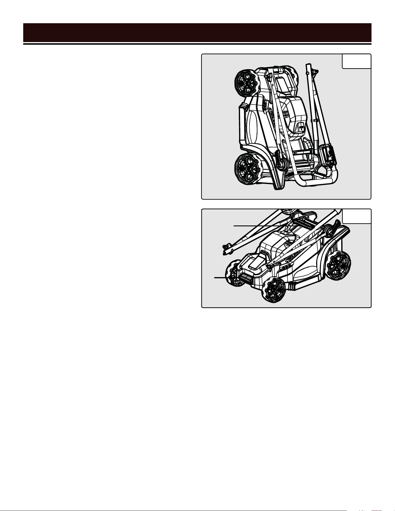
STORING THE MOWER
1. Remove the battery and grass bag when storing the
mower.
1. Loosen the lower handle clamping levers and fold the
handle assembly all the way forward over the battery
housing.
2. Loosen the height adjustment knobs on the upper
handle. Fold the upper handle assembly backwards over
the lower handle.
3. Store the mower in an upright position as shown in
Fig. 13.
TRANSPORTING THE MOWER
1. When transporting the mower, always hold it with two
hands. Place one hand on the handle (Fig. 14 - 1) and the
other on the front grip (Fig. 14 - 2).
Fig.13
Fig.14
1
2
18

19
MAINTENANCE
ROUTINE INSPECTION
Before each use, inspect the general condition of the tool.
If any of these following conditions exist, do not use until
parts are replaced or the sharpener is properly repaired.
Check for:
• Loose hardware or improper mounting
• Misalignment or binding of moving parts
• Damaged battery or battery terminal
• Cracked or broken parts
• Any other condition that may affect its safe operation
CLEANING & STORAGE
1. Brush or blow dust and debris out of the air vents us-
ing compressed air or a vacuum. Keep the air vents free
of obstructions, sawdust, and wood chips. Do not spray,
wash, or immerse the air vents in water.
2. Wipe off the housing and the plastic components us-
ing a moist, soft cloth. Do not use strong solvents or
detergents on the plastic housing or plastic components.
Certain household cleaners may cause damage, and may
cause a shock hazard.
3. Routinely clean out the dust and debris that gathers
under the tension housing, the oil outlet, and around the
bar and the chain sprocket. Otherwise it can jam up the
sprocket, the chain, and the lubrication system.
4. If the pole saw is not used for an extended period of
time, drain the chain oil from the tank. Briefly place the
chain and the guide bar in an oil bath and then wrap in
oil paper to dry.
WARNING! To avoid accidents, turn the tool OFF and remove the battery from the battery terminal before
cleaning, adjusting, or performing any maintenance or lubrication work.
WARNING! Any attempt to repair or replace electrical parts on this tool may be hazardous. Servicing of the
tool must be performed by a qualified technician. When servicing, use only identical WEN replacement parts.
Use of other parts may be hazardous or induce product failure.
STORING THE BATTERY AND CHARGER
• Make sure the battery is fully charged before storage in
order to maximize the life of the battery.
• Do not store the battery pack on the tool. Remove the
battery from the tool before storage.
• After charging, the battery pack may be stored in the
charger, as long as the charger is not plugged in.
• Store the charger at normal room temperature. Do not
store it in excessive heat. Do not use the charger in di-
rect sunlight or in damp conditions. Do not charge out-
side. Recharge at room temperature.
• Keep the charger clean and clear of debris. Do not al-
low foreign material to get into the recessed cavity or
onto the contacts. Wipe the charger clean with a dry
cloth. Do not use solvents or water, and do not place the
charger in wet conditions.
• Always unplug the charger when charging is complete.
Never leave your charger plugged in if it is not charging
a battery.
PRODUCT DISPOSAL
Used power tools should not be disposed of together
with household waste. This product contains electronic
components that should be recycled. Please take this
product to your local recycling facility for responsible
disposal and to minimize its environmental impact.
20
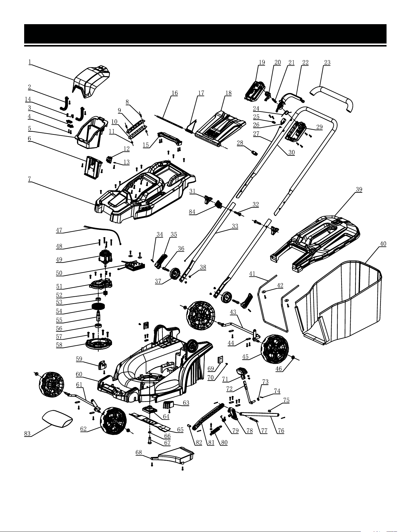
EXPLODED VIEW & PARTS LIST
NOTE: Not all parts may be available for purchase. Parts and accessories that wear
down over the course of normal use are not covered under the warranty.

EXPLODED VIEW & PARTS LIST
NO. PART NO. DESCRIPTION QTY.
1 20835-001 Battery Cover 1
2 20835-002 Hinge 2
3 20835-003 Fixed Shaft 2
4 20835-004 Screw ST4×16 56
5 20835-005 Battery Pack Storage 1
6 20835-006 Battery Pack Fixing Plate 1
7 20835-007 Top Housing 1
8 20835-008 Screw M5×16 2
9 20835-009 Gear Plate 1
10 20835-010 Gear Cover 1
11 20835-011 Nut M5 2
12 20835-012 Battery Pins 1
13 20835-013
Flat washer
φ12xφ4.3x0.8
2
14 20835-014 Spring 1
15 20835-015 Carrying Handle 1
16 20835-016 Shaft 1
17 20835-017 Torsion Spring 1
18 20835-018 Grass bag Holding Flap 1
19 20835-019 Switch Box 1
20 20835-020 Safety Button 1
21 20835-021 Switch Spring 1
22 20835-022 Safety Handle 1
23 20835-023 Handle Grip 1
24 20835-024 Torsional Spring 1
25 20835-025 Cable Clamp 2
26 20835-026 Micro Switch 1
27 20835-027 Signal Line 1
28 20835-028 Wire Clip 1
29 20835-029 Switch Cover 1
30 20835-030 Upper Handle 1
31 20835-031 Knob 2
32 20835-032 Square Neck Bolt M8×45 2
33 20835-033 Lower Handle 2
34 20835-034
Bolt φ4×22
2
35 20835-035 Locking Handle 2
36 20835-036
Quick Locking Bolt
M8×50
2
37 20835-037 Rotating Support Cover 2
NO. PART NO. DESCRIPTION QTY.
38 20835-038 Screw ST4×8 4
39 20835-039 Grass Bag Top Cover 1
40 20835-040 30L Grass Collection Bag 1
41 20835-041 Grass Bag Frame 1
42 20835-042
Flat Washer φ20xφ4x1.5
4
43 20835-043 Rear Axle 1
44 20835-044 Clamp Plate 6
45 20835-045 6.3-Inch Rear Wheels 2
46 20835-046 Nut M6 4
47 20835-047 Power Cord 1
48 20835-048 Screw ST4x30 4
49 20835-049 Brushless Motor 1
50 20835-050 Motor Controller 1
51 20835-051 Upper Gearbox Housing 1
52 20835-052 Pinion 1
53 20835-053
Deep Groove Ball Bearing
6000-ZZ
1
54 20835-054 Bull Wheel 1
55 20835-055 Output Shaft 1
56 20835-056
Deep Groove Ball Bearing
6003-ZZ
1
57 20835-057 Screw ST4.8×25 4
58 20835-058 Lower Gearbox Housing 1
59 20835-059 Right Side Grass Guide 1
60 20835-060 Chassis 1
61 20835-061 Front Axle 1
62 20835-062 5.5-inch Front Wheels 2
63 20835-063 Left Side Grass Guide 1
64 20835-064 Blade Holder 1
65 20835-065 330mm Blade 1
66 20835-066
Spring Washer φ10
1
67 20835-067 M10x1 Bolt (T30) 1
68 20835-068 Grass Exit Damper 1
69 20835-069 Nut Retaining Plate 2
70 20835-070 Screw M4x8 4
71 20835-071 Glove Lift Handle 1
72 20835-072 Handle Lift Mechanism 1
73 20835-073
Washer φ16xφ8.4x2
1
74 20835-074
Pin φ2 x 20
4
21

22
EXPLODED VIEW & PARTS LIST
NO. PART NO. DESCRIPTION QTY.
75 20835-075
Connecting Pin 2 φ10x12
1
76 20835-076 Rear Connecting Rod 1
77 20835-077
Connecting Pin 3 φ10x58
1
78 20835-078 Height Bracket 1
79 20835-079 Torsion Spring Adjuster 1
80 20835-080 Tension Spring Adjuster 1
NO. PART NO. DESCRIPTION QTY.
81 20835-081 Front Connecting Rod 1
82 20835-082
Connecting Pin 1
φ10x20.5
1
83 20835-083
Counterweight Bag
Assembly
1
84 20835-084 Wire Clip 1
NOTE: Not all parts may be available for purchase. Parts and accessories that wear
down over the course of normal use are not covered under the warranty.

WARRANTY STATEMENT
WEN Products is committed to building tools that are dependable for years. Our warranties are consistent with this
commitment and our dedication to quality.
LIMITED WARRANTY OF WEN PRODUCTS FOR HOME USE
GREAT LAKES TECHNOLOGIES, LLC (“Seller”) warrants to the original purchaser only, that all WEN consumer power
tools will be free from defects in material or workmanship during personal use for a period of two (2) years from date
of purchase or 500 hours of use; whichever comes first. Ninety days for all WEN products if the tool is used for pro-
fessional or commercial use. Purchaser has 30 days from the date of purchase to report missing or damaged parts.
SELLER’S SOLE OBLIGATION AND YOUR EXCLUSIVE REMEDY under this Limited Warranty and, to the extent per-
mitted by law, any warranty or condition implied by law, shall be the replacement of parts, without charge, which are
defective in material or workmanship and which have not been subjected to misuse, alteration, careless handling,
misrepair, abuse, neglect, normal wear and tear, improper maintenance, or other conditions adversely affecting the
Product or the component of the Product, whether by accident or intentionally, by persons other than Seller. To make
a claim under this Limited Warranty, you must make sure to keep a copy of your proof of purchase that clearly defines
the Date of Purchase (month and year) and the Place of Purchase. Place of Purchase must be a direct vendor of Great
Lakes Technologies, LLC. Purchasing through third party vendors, including but not limited to garage sales, pawn
shops, resale shops, or any other secondhand merchant, voids the warranty included with this product. Contact tech-
[email protected] or 1-847-429-9263 with the following information to make arrangements: your shipping
address, phone number, serial number, required part numbers, and proof of purchase. Damaged or defective parts and
products may need to be sent to WEN before the replacements can be shipped out.
Upon the confirmation of a WEN representative, your product may qualify for repairs and service work. When returning
a product for warranty service, the shipping charges must be prepaid by the purchaser. The product must be shipped
in its original container (or an equivalent), properly packed to withstand the hazards of shipment. The product must be
fully insured with a copy of the proof of purchase enclosed. There must also be a description of the problem in order
to help our repairs department diagnose and fix the issue. Repairs will be made and the product will be returned and
shipped back to the purchaser at no charge for addresses within the contiguous United States.
THIS LIMITED WARRANTY DOES NOT APPLY TO ITEMS THAT WEAR OUT FROM REGULAR USAGE OVER TIME, IN-
CLUDING BELTS, BRUSHES, BLADES, BATTERIES, ETC. ANY IMPLIED WARRANTIES SHALL BE LIMITED IN DURA-
TION TO TWO (2) YEARS FROM DATE OF PURCHASE. SOME STATES IN THE U.S. AND SOME CANADIAN PROVINCES
DO NOT ALLOW LIMITATIONS ON HOW LONG AN IMPLIED WARRANTY LASTS, SO THE ABOVE LIMITATION MAY
NOT APPLY TO YOU.
IN NO EVENT SHALL SELLER BE LIABLE FOR ANY INCIDENTAL OR CONSEQUENTIAL DAMAGES (INCLUDING BUT
NOT LIMITED TO LIABILITY FOR LOSS OF PROFITS) ARISING FROM THE SALE OR USE OF THIS PRODUCT. SOME
STATES IN THE U.S. AND SOME CANADIAN PROVINCES DO NOT ALLOW THE EXCLUSION OR LIMITATION OF IN-
CIDENTAL OR CONSEQUENTIAL DAMAGES, SO THE ABOVE LIMITATION OR EXCLUSION MAY NOT APPLY TO YOU.
THIS LIMITED WARRANTY GIVES YOU SPECIFIC LEGAL RIGHTS, AND YOU MAY ALSO HAVE OTHER RIGHTS WHICH
VARY FROM STATE TO STATE IN THE U.S., PROVINCE TO PROVINCE IN CANADA AND FROM COUNTRY TO COUN-
TRY.
THIS LIMITED WARRANTY APPLIES ONLY TO ITEMS SOLD WITHIN THE UNITED STATES OF AMERICA, CANADA
AND THE COMMONWEALTH OF PUERTO RICO. FOR WARRANTY COVERAGE WITHIN OTHER COUNTRIES, CONTACT
THE WEN CUSTOMER SUPPORT LINE. FOR WARRANTY PARTS OR PRODUCTS REPAIRED UNDER WARRANTY
SHIPPING TO ADDRESSES OUTSIDE OF THE CONTIGUOUS UNITED STATES, ADDITIONAL SHIPPING CHARGES MAY
APPLY.
23

V. 2024.09.02
THANKS FOR
REMEMBERING