AP15761.(04/10).....
!
..FOR YOUR SAFETY!
—. Do not store or use gasoline or other
flammable vapors or liquids or other
combustible materials in the vicinity of this or
any other appliance. To do so may result in an
explosion or fire.
—. WHAT TO DO IF YOU SMELL GAS
● Do not try to light any appliance.
● .Do not touch any electrical switch; do not
use any phone in your building.
● .Immediately call your gas supplier from a
neighbor’s phone. Follow the gas supplier’s
instructions.
● .If you cannot reach your gas supplier, call
the fire department.
● .Do not return to your home until authorized
by the gas supplier or fire department.
—..Improper installation, adjustment, alteration,
service or maintenance can cause property
damage, personal injury, or death. Refer to
this manual. Installation and service must be
performed by a qualified installer, service
agency or the gas supplier.
.WARNING: If the information in these instructions is not followed exactly,
a fire or explosion may result causing property damage, personal injury or death.
!
The.purpose.of.this.manual.is.twofold:.one,.to.provide.the.installer.with.the.basic.
directions.and.recommendations.for.the.proper.installation.and.adjustment.of.the.water.
heater;.and.two,.for.the.owner–operator,.to.explain.the.features,.operation,.safety.
precautions,.maintenance.and.troubleshooting.of.the.water.heater.This.manual.also.
includes.a.parts.list
It.is.very.important.that.all.persons.who.are.expected.to.install,.operate.or.adjust.this.
water.heater.read.the.instructions.carefully.so.they.may.understand.how.to.perform.
these.operations.If.you.do.not.understand.these.instructions.or.any.terms.within.it,.seek.
professional.assistance
Any.questions.regarding.the.operation,.maintenance,.service.or.warranty.of.this.water.
heater.should.be.directed.to.the.seller.from.whom.it.was.purchased.If.additional.
information.is.required,.refer.to.the.section.on.“If.you.need.service”
Do not destroy this manual. Please read carefully and keep in a safe place for
future reference.
!
Recognize this symbol as an indication of Important Safety Information!
!
.
California Proposition 65 Warning:.This.product.contains.chemicals.known.to.
the.State.of.California.to.cause.cancer,.birth.defects.or.other.reproductive.harm
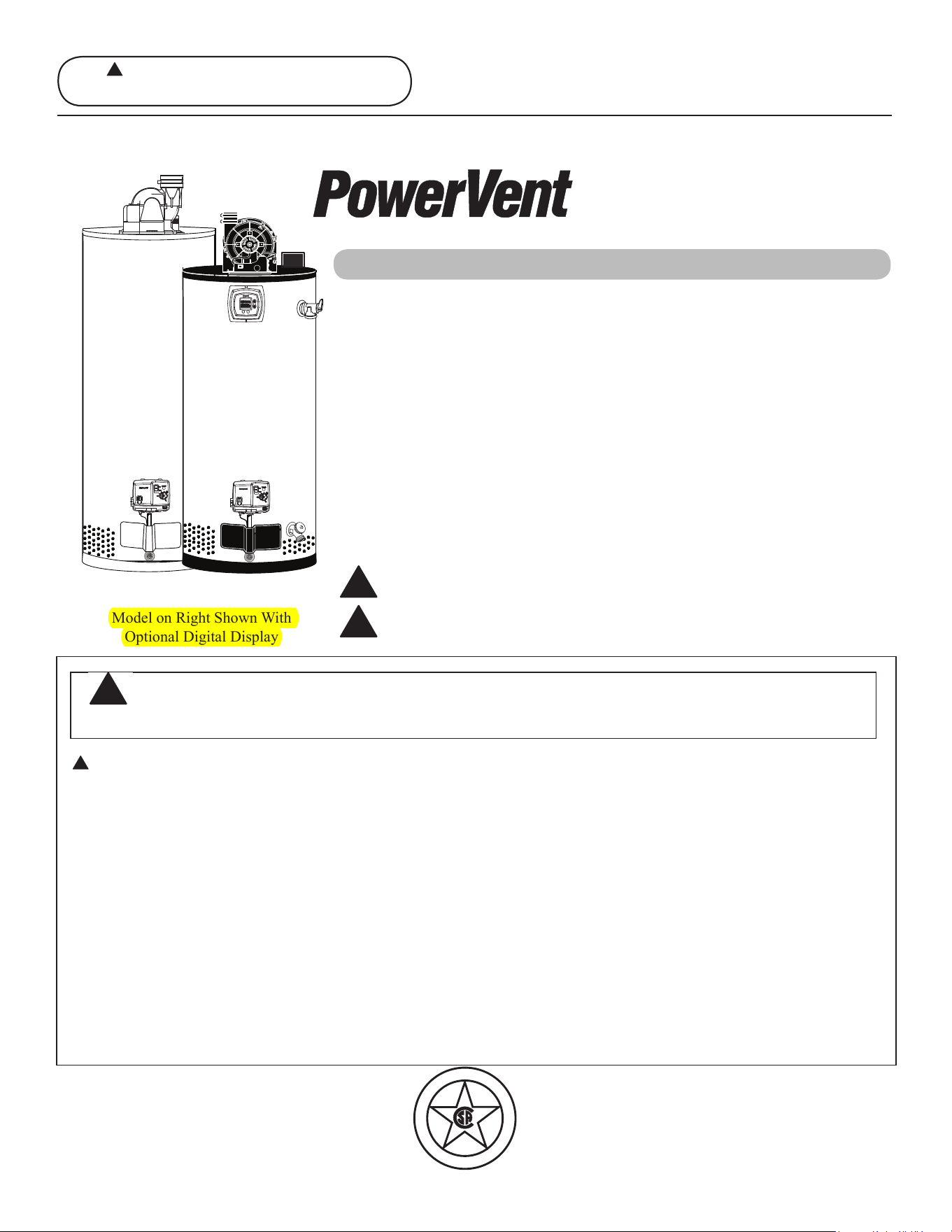
Residential.40.And.50.Gallon
Use.&.Care.Manual
With.Installation.Instructions.for.the.Installer
Printed in USA
Water.Heaters
D
E
S
I
G
N
C
E
R
T
I
F
I
E
D
®
!
Warning: This water heater is not
suitable for use in manufactured (mobile) homes!
®
Residential.Gas.-.FVIR Certified
Model.on.Right.Shown.With.
Optional.Digital.Display
Energy Star II
Care and Cleaning
Draining. .32
Maintenance. .32
Vent.System.Inspection. .33
Burner.Inspection . .33
Extended.Shut-Down. 34
Safety Information
Safety.Precautions. .3–6
LP.Gas.Models . .5
Installation Instructions
Location. .7
Water.Supply.Connections. .9
Gas.Supply. .11
Venting. 12-16
Wiring.Diagram. 17,.18
Pipe.Insulation. 19
Install.User.Display. 20-21
User.Display.Operation. 22-24
Heat.Traps . 25
Installation.Checklist. 26
Potable/Space.Heating . .27
Operating Instructions
Lighting.Instructions. .28
Water.Temperature . 29-31
Troubleshooting Tips
Before.You.Call.
For.Service. .35-37
Customer Service
Parts.List. .38
If.You.Need.Service . 40
FOR.YOUR.RECORDS
Write.the.model.and.serial.numbers.here:
#
#
You.can.find.them.on.a.label.on.the.appliance
Staple sales slip or cancelled check here..
Proof.of.the.original.purchase.date.is.needed.to.obtain.service.under.
the.warranty
2
Inside.you.will.find.many.helpful.hints.on.how.to.use.and.maintain.
your.water.heater.properly.A.little.preventive.care.on.your.part.can.
save.you.time.and.money.over.the.life.of.your.water.heater
You’ll.find.many.answers.to.common.problems.in.the.
Troubleshooting.Guide.If.you.review.the.chart.of.Troubleshooting.
Tips.first,.you.may.not.need.to.call.for.service
READ.THIS.MANUAL
Your safety and the safety of others are very important. There
are many important safety messages in this manual and on your
appliance. Always read and obey all safety messages.
!
This is the safety alert symbol. Recognize this symbol
as an indication of Important Safety Information!
This symbol alerts you to potential hazards that can
kill or hurt you and others.
All safety messages will follow the safety alert symbol and
either the word “DANGER”, “WARNING”, “CAUTION” or
“NOTICE”.
These words mean:
!
DANGER
An imminently hazardous situation
that will result in death or serious
injury.
!
WARNING
A potentially hazardous situation that
could result in death or serious injury
and/or damage to property.
!
CAUTION
A potentially hazardous situation that
may result in minor or moderate
injury.
Notice:
Attention is called to observe a
specified procedure or maintain
a specific condition.
READ.THE.SAFETY.INFORMATION
Be sure to read and understand the entire Use and Care Manual before attempting to install or operate this water
heater. It may save you time and money. Pay particular attention to the Safety Instructions. Failure to follow these
warnings could result in serious bodily injury or death. Should you have problems understanding the instructions in
this manual, or have any questions, STOP, and get help from a qualified service technician, or the local gas utility.
IMPORTANT.SAFETY.INFORMATION
READ.ALL.INSTRUCTIONS.BEFORE.USING
3
Failure to install the blower assembly and properly vent the water heater to the outdoors
as outlined in the Venting Section of the Installation Instructions in this manual can result
in unsafe operation of the water heater. To avoid the risk of fire, explosion, or asphyxiation
from carbon monoxide, never operate this water heater unless it is properly vented and
has an adequate air supply for proper operation. Be sure to inspect the vent system for
proper installation at initial start-up; and at least annually thereafter. Refer to the Care and
Cleaning section of this manual for more information regarding vent system inspection.
DANGER!
INSTALL.THE.BLOWER.ASSEMBLY.AND.PROPERLY.VENT.
THE.WATER.HEATER
Gasoline, as well as other flammable materials and liquids (which include but are not
limited to adhesives, solvents, paint thinners etc.), and the vapors they produce are
extremely dangerous. DO NOT handle, use or store gasoline or other flammable or
combustible materials anywhere near or in the vicinity of a water heater or any other
appliance. Be sure to read and follow warning label pictured below and other labels on the
water heater, as well as the warnings printed in this manual. Failure to do so can result in
property damage, bodily injury or death.
WARNING!
!
!
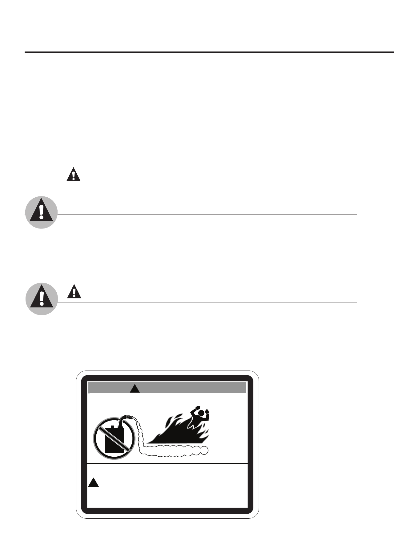
FLAMMABLES
Flammable Vapors
FIRE AND EXPLOSION HAZARD
Can result in serious injury or death.
Do not store or use gasoline or other flammable vapors and liquids
in the vicinity of this or any other appliance. Storage of or use of gasoline
or other flammable vapors or liquids in the vicinity of this or any other
appliance can result in serious injury or death.
W A R N I N G
NOTICE: This water heater is equipped with a flammable vapor sensor that will automatically shut
down the water heater in the presence of gasoline vapors and some other flammable vapors. If the
flammable vapor sensor shuts down the water heater, contact a qualified service technician. Clear any
hazardous materials and ventilate the area around the water heater. Do not turn off the appliance
or adjust the ON/OFF switch in any way. Do not tamper with the flammable vapor sensor. Do not
submerse the flammable vapor sensor in water. Do not allow the flammable vapor sensor to come into
contact with any substances such as bleach or cleaners. See the “Gas Valve LED Error Code” Section
of this manual for a list of error codes.
Time/Temperature Relationship in Scalds
...Water.Temperature. Time.To.Produce.a.Serious.Burn
. 120°F More than 5 minutes
125°F 1
1
/2 to 2 minutes
130°F About 30 seconds
135°F About 10 seconds
140°F Less than 5 seconds
145°F Less than 3 seconds
150°F About 1
1
/2 seconds
155°F About 1 second
Table.courtesy.of.Shriners.Burn.Institute
The.chart.shown.above.may.be.used.as.a.guide.in.
determining.the.proper.water.temperature.for.your.
home
DANGER: Households with small children, disabled,
or elderly persons may require a 120°F or lower gas control
(thermostat) setting to prevent contact with “HOT” water.
Maximum.water.temperatures.occur.just.after.the.
burner.has.shut.off.To.find.water.temperature.being.
delivered,.turn.on.a.hot.water.faucet.and.place.
a.thermometer.in.the.water.stream.and.read.the.
thermometer.(See.page.24.and.25.for.more.details)
The.temperature.of.the.water.in.the.heater.can.be.
regulated.by.rotating.the.dial.on.the.front.of.the.
gas.control.(thermostat)..To.comply.with.safety.
regulations.the.gas.control.(thermostat).was.set.
at.“HOT”.position.before.the.water.heater.was.
shipped.from.the.factory..The.“HOT”.dial.position.
corresponds.to.a.water.temperature.of.approximately.
120°F
The.illustration.below.details.the.approximate.water.
temperature.for.each.mark.on.the.Gas.Control.
(Thermostat).Temperature.Dial
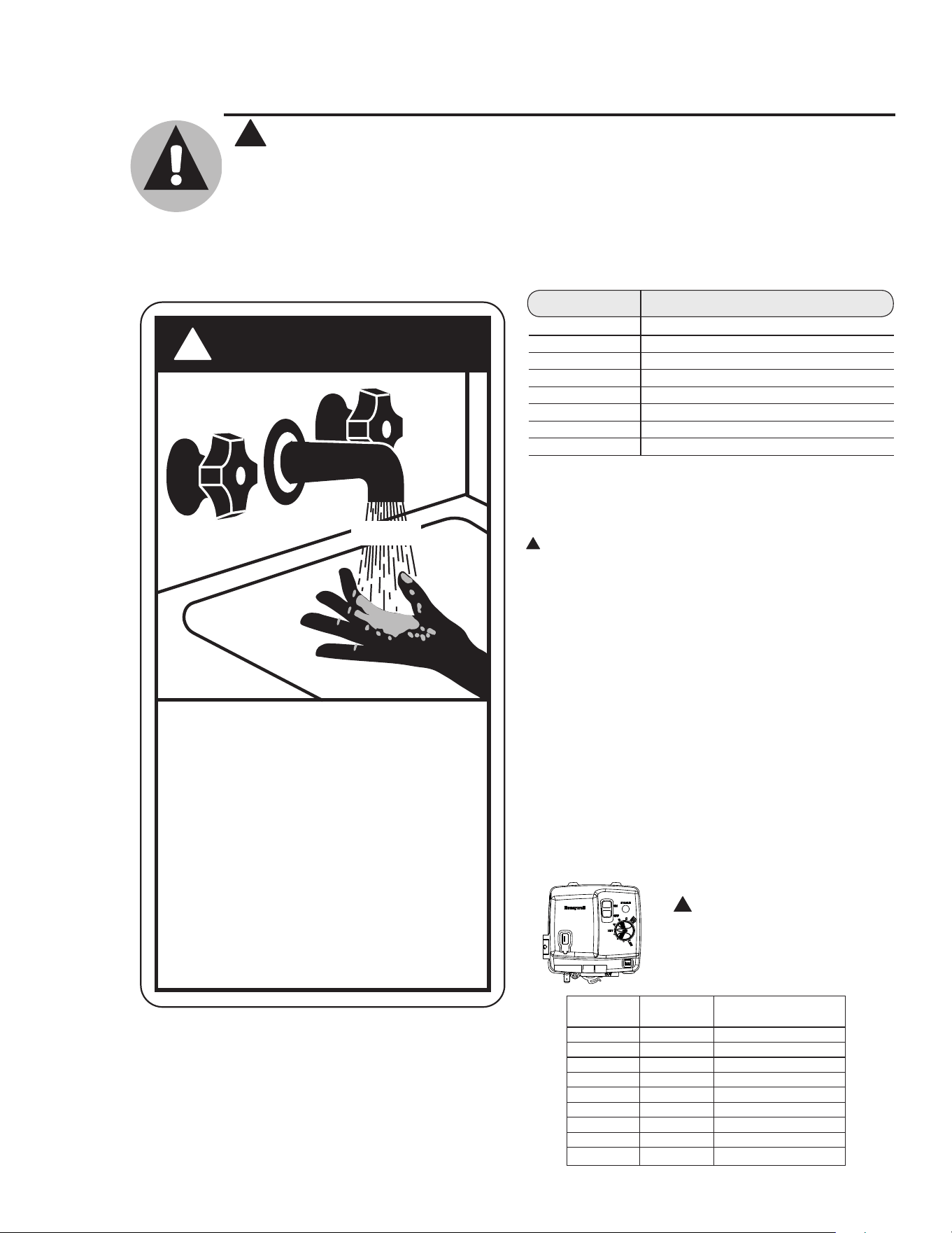
D A N G E R
!
HOT
Water temperature over 125°
can
cause severe burns
instantly or
death from scalds.
Children, disabled and elderly are
at highest risk of being scalded.
See instruction manual before
setting temperature at water
heater.
Feel water before bathing or
showering.
Temperature limiting valves are
available, see manual.
BURN
F (52°C)
!
DANGER!
WATER.TEMPERATURE.SETTING
Safety and energy conservation are factors to be considered when selecting the water
temperature setting of a water heater’s gas control. Water temperatures above 125°F
can cause severe burns or death from scalding. Be sure to read and follow the warnings
outlined on the label pictured below. This label is also located on the water heater.
Notice: Mixing valves are available for reducing point
of use water temperature by mixing hot and cold water
in branch water lines. Contact a licensed plumber or the
local plumbing authority for further information.
4
IMPORTANT.SAFETY.INFORMATION
READ.ALL.INSTRUCTIONS.BEFORE.USING
!
Valve.Set.
Point
Estimated.
Temperature
Burns.on.Adult.Skin
LOW
90°F ------------------------
●
98°F ------------------------
●
105°F ------------------------
●
113°F ------------------------
HOT
120°F More.than.5.minutes
A
130°F About.30.seconds
B
140°F Less.than.5.seconds
C
150° About.1-1/2.seconds
VERY.HOT
160°F About.1/2.second
!
DANGER: Hotter
water increases the
potential for Hot Water
SCALDS.
5
LP and Natural gas have an odorant added to aid in detecting a gas leak. Some people
may not physically be able to smell or recognize this odorant. If you are unsure or
unfamiliar with the smell of LP or natural gas, ask the gas supplier. Other conditions,
such as “odorant fade”, which causes the odorant to diminish in intensity, can also hide or
camouflage a gas leak.
DANGER!
LIqUEFIED.PETROLEUM.(LP....PROPANE.OR.BUTANE).
AND.NATURAL.GAS.MODELS
● Water heaters utilizing LP gas are
different from natural gas models. A
natural gas water heater will not function
safely on LP gas and vice versa.
● No attempt should ever be made to
convert the water heater from natural
gas to LP gas. To avoid possible
equipment damage, personal injury or
fire, do not connect the water heater to a
fuel type not in accordance with the unit
data plate. LP for LP units. Natural gas
for natural gas units. These units are not
certified for any other fuel type.
● LP appliances should not be installed
below grade (for example, in a basement)
if such installation is prohibited by
federal, state and/or local laws, rules,
regulations or customs.
● LP gas must be used with great caution.
It is heavier than air and will collect first
in lower areas making it hard to detect at
nose level.
● Before attempting to light the water
heater, make sure to look and smell for
gas leaks. Use a soapy solution to check
all gas fittings and connections. Bubbling
at a connection indicates a leak that must
be corrected. When smelling to detect a
gas leak, be sure to sniff near the floor
also.
● Gas detectors are recommended in LP
& natural gas applications and their
installation should be in accordance
with the detector manufacturer’s
recommendations and/or local laws,
rules, regulations or customs.
● It is recommended that more than one
method, such as soapy solution, gas
detectors, etc., be used to detect leaks in
gas applications.
!
DANGER: If a gas leak is present or
suspected:
● Donotattempt to find the cause
yourself.
● Donot try to light any appliance.
● Donot touch any electrical switch.
● Donot use any phone in your building.
● Leave the house immediately and make
sure your family and pets leave also.
● Leave the doors open for ventilation
and contact the gas supplier, a qualified
service agency or the fire department.
● Stay away from the house (or building)
until the service call has been made, the
leak is corrected and a qualified agency
has determined the area to be safe.
6
IMPORTANT.SAFETY.INFORMATION
READ.ALL.INSTRUCTIONS.BEFORE.USING
!
WARNING!
For your safety, the information in this manual must be followed to minimize the risk of
fire or explosion, electric shock, or to prevent property damage, personal injury, or loss of
life.
FOR.INSTALLATIONS.IN.THE.STATE.OF.CALIFORNIA
California Law requires that residential water heaters must be braced, anchored or
strapped to resist falling or horizontal displacement due to earthquake motions. For
residential water heaters up to 52-gallon capacity, a brochure with generic earthquake
bracing instructions can be obtained from: Office of the State Architect, 1102 Q Street,
Suite 5100, Sacramento, CA 95814 or you may call 916-445-8100 or ask a water heater
dealer.
However, applicable local codes shall govern installation. For residential water heaters
of a capacity greater than 52 gallons, consult the local building jurisdiction for acceptable
bracing procedures.
Have.the.installer.show.you.the.location.of.the.gas.shut-off.valve.and.how.to.shut.it.off.
if.necessary.Turn.off.the.manual.shut-off.valve.if.the.water.heater.has.been.subjected.to.
overheating,.fire,.flood,.physical.damage.or.if.the.gas.supply.fails.to.shut.off
● Read.this.manual.entirely.before.installing.
or.operating.the.water.heater
● Use.this.appliance.only.for.its.intended.
purpose.as.described.in.this.Use.and.Care.
Manual
● Be.sure.your.appliance.is.properly.installed.
in.accordance.with.local.codes.and.the.
provided.installation.instructions.
● Do not attempt.to.repair.or.replace.any.part.
of.your.water.heater.unless.it.is.specifically.
recommended.in.this.manual.All.other.
servicing.should.be.referred.to.a.qualified.
technician
SAFETY.PRECAUTIONS
READ.AND.FOLLOW.THIS.SAFETY.INFORMATION.
CAREFULLY
SAVE.THESE.INSTRUCTIONS
Combustion.Air.Inlet.
Openings
Installing the water heater.
This water heater must be installed in accordance with these instructions, local codes, utility company
requirements, and/or in the absence of local codes, use the latest edition of the American National
Standard/National Fuel Gas Code. A copy can be purchased from either the American Gas Association,
400 N. Capitol Street NW, Washington, DC 20001 as ANSI standard Z223.1 or National Fire Protection
Association, 1 Batterymarch Park, Quincy, MA 02269 as booklet NFPA 54.
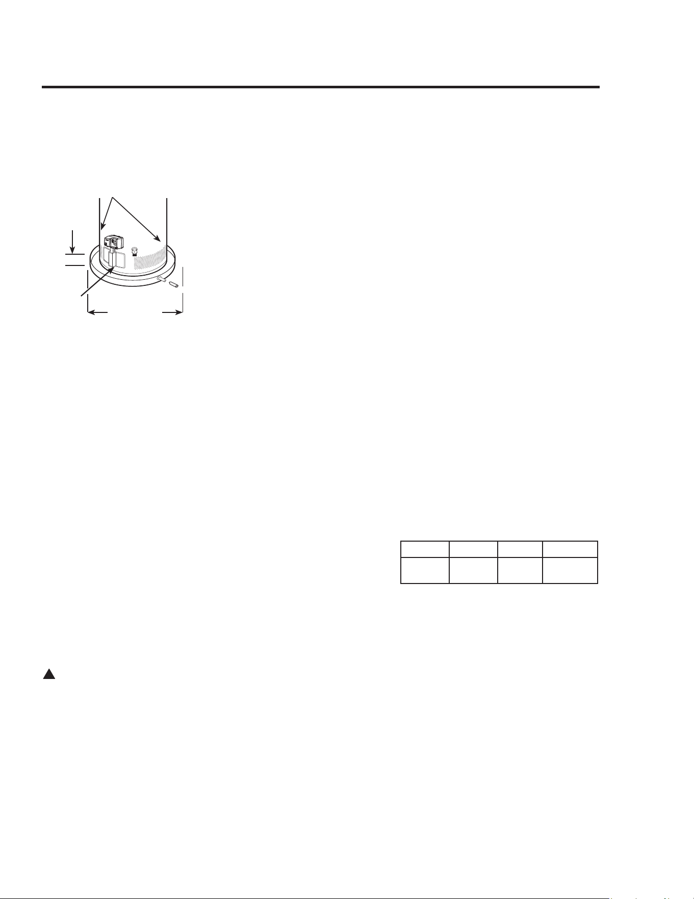
Location
The water heater should not be located
in an area where leakage from the tank
or connections will result in damage
to the area adjacent to the heater or to
lower floors of the structure.
When such areas cannot be avoided it is
recommended that a suitable catch pan,
adequately drained, must be installed
under the water heater.
The water heater must be centered in
the catch pan.
The catch pan must not restrict air
flow to the combustion air inlet openings
(perforation openings) located around the
lower perimeter of the water heater.
Catch pan kits are available from
the store where the water heater
was purchased, or any water heater
distributor.
Make.certain.the.floor.underneath.the.
water.heater.is.strong.enough.to.
sufficiently.support.the.weight.of.the.
water.heater.once.it.is.filled.with.water
A.gas.fired.water.heater.or.any.other.
appliance.should.not.be.installed..
in.a.space.where.liquids.which.give.off.
flammable.vapors.are.to.be.used.or.stored..
Such.liquids.include.gasoline,.LP.gas.
(butane.or.propane),.paint.or.adhesives.
and.their.thinners,.solvents.or.removers
DO NOT block or obstruct any of the
combustion air inlet openings located
around the perimeter of the water
heater. A minimum of 1” is required
between these combustion air inlet
openings and any obstruction.
DO NOT obstruct or block the
Flammable Vapor Sensor.
Because.of.natural.air.movement.in.a.
room.or.other.enclosed.space,.flammable.
vapors.can.be.carried.some.distance.from.
where.liquids.which.give.off.flammable.
vapors.are.to.be.used.or.stored.The.open.
flame.of.the.water.heater’s.pilot.or.main.
burner.can.ignite.these.vapors.and.create.
a.shut.down.condition.of.the.water.heater.
which.will.not.allow.the.water.heater.
to.ignite.until.examined.by.a.qualified.
Service.Technician
FVIR.certified.gas.water.heaters.can.
be.installed.on.a.residential.garage.
floor.without.the.use.of.an.18".stand.in.
accordance.with.the.National.Fuel.Gas.
Code,.NFPA.54,.ANSI.Z2231.2006,.
unless.otherwise.directed.by.State.and.
Local.code.requirements..The.water.
heater.must.be.located.so.it.is.not.subject.
to.physical.damage,.for.example,.by.
moving.vehicles,.area.flooding.etc
●..The.water.heater.should.be.installed.
so.as.to.minimize.the.length.of.plastic.
vent.pipe.and.the.number.of.vent.
connection.fittings.required..(Refer.to.
the.“INSTALLATION”.Section.of.this.
manual)
●..Long.hot.water.lines.should.be.insulated.
to.conserve.water.and.energy.
●..The.water.heater.and.water.lines.should.
be.protected.from.exposure..
to.freezing.temperatures
●..DO NOT.install.the.water.heater.in.
bathrooms,.bedrooms,.any.occupied.
rooms.normally.kept.closed,.or.in.
unprotected.outdoor.areas
●..Minimum.clearance.from.combustible.
construction:..
If.the.clearances.stated.on.the.
Instruction/Warning.Label,.located.on.
the.front.of.the.heater.differ,.install.the.
water.heater.according.to.the.clearances.
stated.on.the.label
●..If.the.water.heater.is.installed.in.an.
alcove.or.closet,.the.entire.floor.must.
be.covered.by.a.wood.or.metal.panel.
A.minimum.of.24”.clearance.from.the.
front.and.top.should.be.available.for.
adequate.inspection.and.servicing
●..The.water.heater.may.be.installed.on.
combustible.floors,.but.not.directly.on.
carpeting.If.the.water.heater.must.be.
installed.on.carpeting,.place.a.metal.or.
wood.panel.beneath.the.water.heater,.
extending.beyond.its.full.width.and.
depth.at.least.3”.in.all.directions
The auxiliary catch pan
installation MUST conform
to local codes.
Diameter.of.
water.heater.
plus.2”.min
Max.
275”
!
WARNING: Combustible
construction refers to
adjacent walls and ceilings
and should not be confused
with combustible or
flammable products and
materials. Combustible
and/or flammable products
and materials should never
be stored in the vicinity of
this or any gas appliance.
Front Sides Rear Top
3”.
(76.cm)
1”.
(25.cm)
0”.
(0.cm)
12”.
(305.cm)
7
Notice: DO NOT allow
the flammable vapor
sensor to become
submerged in water.
Make sure the catch pan
is properly drained.
Flammable.
Vapor.
Sensor
Notice: DO NOT allow
the catch pan to obstuct
the flammable vapor
sensor.

8
Installing the water heater.
Combustion and Ventilation Air
Ventilation (ambient) air temperature
must be 100°F or less. Proper operation
of the water heater requires air for
combustion and ventilation. Provisions
for combustion and ventilation air
must comply with referenced codes and
standards.
DO NOT block or obstruct any of the
combustion air inlet openings located
around the perimeter of the water
heater. A minimum of 1” is required
between these combustion air inlet
openings and any obstruction.
NOTICE: If the water heater is
installed in an unconfined space within a
building of conventional frame, masonry
or metal construction, infiltration
air is normally adequate for proper
combustion and ventilation. If the
water heater is installed in a confined
space, provisions for combustion and
ventilation air must be made.
DO NOT.obstruct.or.block.the.Flammable.
Vapor.Sensor
A.confined.space.is.one.having.a.volume.
of.less.than.50.cubic.feet.per.1000.Btuh.
of.the.aggregate.input.of.all.appliances.
within.that.space.
The.air.must.be.supplied.through.two.
permanent.openings.of.equal.area.One..
is.to.be.located.within.12”.above.the.floor.
and.the.other.is.to.be.located.within.12”.
from.the.ceiling
The.minimum.net.free.area.of.each.opening.
must.not.be.less.than.one.square.inch.
per.1000.Btuh.of.the.total.input.rating.
of.all.the.appliances.in.the.enclosure.
(but.not.less.than.100.square.inches),.if.
each.opening.communicates.with.other.
unconfined.areas.inside.the.building
Buildings.of.unusually.tight.construction.
shall.have.the.combustion.and.ventilation.
air.supplied.from.outdoors,.or.a.freely.
ventilated.attic.or.crawl.space
If.air.is.supplied.from.outdoors,.directly.or.
through.vertical.ducts,.there.must.be.two.
openings.located.as.specified.above.and.
each.must.have.a.minimum.net.free.area.
of.not.less.than.one.square.inch.per.4000.
Btuh.of.the.total.input.rating.of.all.the.
appliances.in.the.enclosure
If.horizontal.ducts.are.used.to.
communicate.with.the.outdoors,.each.
opening.must.have.a.minimum.net.free.
area.of.not.less.than.one.square.inch.per.
2000.Btuh.of.the.total.input.rating.of.all.
the.appliances.in.the.enclosure.If.ducts.
are.used,.the.minimum.dimensions.of.
rectangular.air.ducts.shall.not.be.less.than.
3”
NOTICE: If the duct openings which
supply combustion and ventilation air
are to be covered with a protective
screen or grill, the net free area
(openings in the material) of the
covering material must be used in
determining the size of the openings.
Protective screening for the openings
MUST NOT be smaller than 1/4”mesh
to prevent clogging by lint or other
debris.
Corrosive Atmospheres
The.air.in.beauty.shops,.dry.cleaning.
establishments,.photo.processing.
labs,..and.storage.areas.for.liquid.and.
powdered.bleaches.or.swimming.pool.
chemicals.often.contain.such.halogenated.
hydrocarbons
An.air.supply.containing.halogenated.
hydrocarbons.may.be.safe.to.breathe,..
but.when.it.passes.through.a.gas.flame.
corrosive.elements.are.released.that..
will.shorten.the.life.of.any.gas.burning.
appliance
Propellants.from.common.spray.cans.
or.gas.leaks.from.A/C.and.refrigeration.
equipment.are.highly.corrosive.after.
passing.through.a.flame
The.water.heater.warranty.is.voided.when.
failure.of.the.heater.is.due.to.operation.in.
a.corrosive.atmosphere
NOTICE: The water heater
should not be installed near
an air supply containing
halogenated hydrocarbons.
Inspect Shipment
Inspect.the.water.heater.for.possible.damage.Check.the.markings.on.the.rating.plate.of.
the.water.heater.to.be.certain.the.type.of.gas.supplied.corresponds.to.the.water.heater.
requirements
NOTICE: Do not install the
water heater in attics where
the temperature may exceed
100°F. This water heater is
equipped with a temperature
sensing device that will
shut off the water heater
if the maximum allowable
vent pipe temperature is
exceeded.
Thermal Expansion
Determine if a check valve exists in the inlet
water line. Check with your local water
utility company...It.may.have.been.installed.
in.the.cold.water.line.as.a.separate.back.flow.
preventer,.or.it.may.be.part.of.a.pressure.
reducing.valve,.water.meter.or.water.softener.
A.check.valve.located.in.the.cold.water.inlet.
line.can.cause.what.is.referred.to.as.a.“closed
water system”.A.cold.water.inlet.line.with.no.
check.valve.or.back.flow.prevention.device.is.
referred.to.as.an.“open”.water.system
As.water.is.heated,.it.expands.in.volume.and.
creates.an.increase.in.the.pressure.within.the.
water.system.This.action.is.referred.to.as.
“thermal expansion”.In.an.“open”.water.
system,.expanding.water.which.exceeds.the.
capacity.of.the.water.heater.flows.back.into.
the.city.main.where.the.pressure.is.easily.
dissipated
A.“closed water system”,.however,.prevents.
the.expanding.water.from.flowing.back.into.the.
main.supply.line,.and.the.result.of “thermal
expansion”.can.create.a.rapid.and.dangerous.
pressure.increase.in.the.water.heater.and.
system.piping.This.rapid.pressure.increase.can.
quickly.reach.the.safety.setting.of.the.relief.
valve,.causing.it.to.operate.during.each.heating.
cycle.Thermal.expansion,.and.the.resulting.
rapid,.and.repeated.expansion.and.contraction.
of.components.in.the.water.heater.and.piping.
system.can.cause.premature.failure.of.the.relief.
valve,.and.possibly.the.heater.itself.Replacing.
the.relief.valve.will not.correct.the.problem!
The.suggested.method.of.controlling.thermal.
expansion.is.to.install.an.expansion.tank.in.
the.cold.water.line.between.the.water.heater.
and.the.check.valve.(see.illustration.below).
The.expansion.tank.is.designed.with.an.air.
cushion.built.in.that.compresses.as.the.system.
pressure.increases,.thereby.relieving.the.over.
pressure.condition.and.eliminating.the.repeated.
operation.of.the.relief.valve.Other.methods.
of.controlling.thermal.expansion.are.also.
available.Contact.your.installing.contractor,.
water.supplier.or.plumbing.inspector.for.
additional.information.regarding.this.subject
Refer.to.the.illustration.below.for.suggested.
typical.installation.The.installation.of.unions.
or.flexible.copper.connectors.is.recommended.
on.the.hot.and.cold.water.connections.so.that.
the.water.heater.may.be.easily.disconnected.
for.servicing.if.necessary.The.HOT.and.COLD.
water.connections.are.clearly.marked.and.are.
3/4”.NPT.on.all.models.Install.a.shut-off.valve.
in.the.cold.water.line.near.the.water.heater
Water Supply Connections
IMPORTANT: Do not apply
heat to the HOT or COLD
water connections. If sweat
connections are used, sweat
tubing to adapter before
fitting adapter to the cold
water connections on heater.
Any heat applied to the cold
water supply fittings will
permanently damage the
dip tube and heat traps.
NOTICE: The National
Fuel Gas Code (NFGC)
mandates a manual
gas shut-off valve: See
(NFGC) for complete
instructions. Local codes
or plumbing authority
requirements may vary
from the instructions or
diagrams provided and
take precedent over these
instructions.
Vacuum Relief Valve
(Not Supplied)
If required, install per local codes
and valve manufacturer’s
instructions.
9
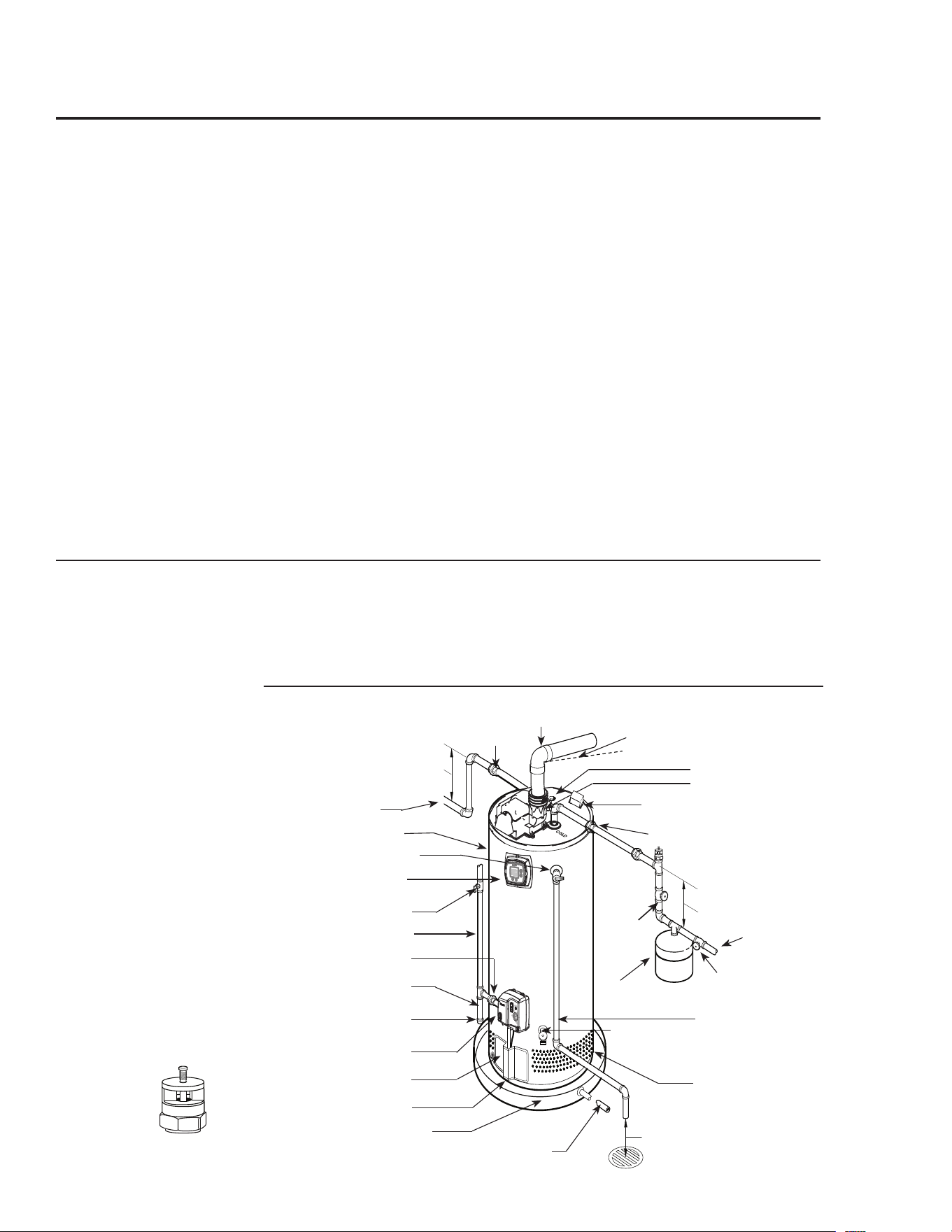
Heat.trap.
6”.minimum
Heat.trap.
6”.minimum
Union
To.gas.supply
Sediment.trap
Cap
Ground.joint.union
Drain.Pan.Pipe.
to.suitable.drain
Drain.
valve
Relief.valve.discharge.
line.to.suitable.open.
drain
To.cold.water.
supply
6”.Air.gap
Blower.assembly
1/4”.per.foot.maximum.slope.up.or.
down.for.horizontal.venting
Auxiliary.catch.pan
Union
Anode
Vent.connector
Thermostatic.gas.valve
Jacket.door
Manual.gas.shut-off
Temperature.and.pressure.
relief.valve
Shut-off.valve
Shut-off.
valve
Thermal.expansion.
tank.(if.required)
Combustion.Air.
Inlet.Openings
Hot.water.outlet.to.
fixtures
Water.Heater.Jacket
Flammable.Vapor.Sensor
Typical Installation
Remote.Control
Transformer.Box.
(Remote.Control.Models.Only)
.....(Optional)
10
Installing the water heater.
A new combination temperature and pressure relief valve, complying with the Standard for Relief Valves
and Automatic Gas Shut-Off Devices for Hot Water Supply Systems, ANSI Z21.22, is supplied and must
remain in the opening provided and marked for the purpose on the water heater. No valve of any type
should be installed between the relief valve and the tank. Local codes shall govern the installation of
relief valves.
Relief Valve
The.pressure.rating.of.the.relief.valve.
must.not.exceed.150.PSI,.the.maximum.
working.pressure.of.the.water.heater.as.
marked.on.the.rating.plate.
The.Btuh.rating.of.the.relief.valve.must.
equal.or.exceed.the.Btuh.input.of.the.
water.heater.as.marked.on.its.rating.plate
Position.the.outlet.of.the.relief.valve.
above.a.suitable.open.drain.to.eliminate.
potential.water.damage.Piping.used.
should.be.of.a.type.approved.for.hot.water.
distribution.
The.discharge.line.must.be.no.smaller.
than.the.outlet.of.the.valve.and.must.
pitch.downward.from.the.valve.to.allow.
complete.drainage.(by.gravity).of.the.
relief.valve.and.discharge.line.
The.end.of.the.discharge.line.should.not.
be.threaded.or.concealed.and.should.be.
protected.from.freezing.No.valve.of.
any.type,.restriction,.or.reducer.coupling.
should.be.installed.in.the.discharge.line
To Fill the Water Heater
Make.certain.that.the.drain.valve.is.
closed,.then.open.the.shut-off.valve.in.the.
cold.water.supply.line
Open.each.hot.water.faucet.slowly.to.
allow.the.air.to.vent.from.the.water..
heater.and.piping.
A.steady.flow.of.water.from.the.hot.water.
faucet(s).indicates.a.full.water.heater
Do.not.allow.the.flammable.vapor.sensor.
to.become.submerged.in.water
WARNING: The tank
must be full of water before
heater is turned on. The
water heater warranty does
not cover damage or failure
resulting from operation
with an empty or partially
empty tank.
Condensation
Condensation.can.form.on.the.tank.
when.it.is.first.filled.with.water.
Condensation.might.also.occur.with.a.
heavy.water.draw.and.very.cold.inlet.
water.temperatures.
Drops.of.water.falling.on.the.burner.can.
produce.a.sizzling.or.pinging.sound
This.condition.is.not.unusual,.and.will.
disappear.after.the.water.becomes.heated.
If,.however,.the.condensation.continues,.
examine.the.piping.and.fittings.for.
possible.leaks
WARNING: Do not attempt to convert this water heater for use with a different type of gas other than the type
shown on the rating plate. Such conversion could result in hazardous operating conditions.
Leak Testing
The.water.heater.and.its.gas.connections.
must.be.leak.tested.at.normal.operating.
pressures.before.it.is.placed.in.operation
...Turn.on.the.manual.gas.shut-off.
valve.near.the.water.heater
...Use.a.soapy.water.solution.to.test.for.
leaks.at.all.connections.and.fittings.
Bubbles.indicate.a.gas.leak.that.must.
be.corrected.
The.factory.connections.to.the.gas.
control.(thermostat).should.also.be.leak.
tested.after.the.water.heater.is.placed.in.
operation
High Altitude
Input.rating.of.this.water.heater.is.
based.on.sea.level.operation..At.higher.
elevations.the.actual.input.rate.may.be.
lower.than.the.value.listed.on.the.rating.
label.due.to.the.derating.of.natural.gas.and.
LP.gas..This.water.heater.can.be.installed.
at.elevation.up.to.2,000.feet.without.any.
change.or.modification
For.installation.between.2,000.and.7,700.
feet,.refer.to.the.Venting.Information.
tables.on.page.13.and.14.for.maximum.
vent.lengths
Installations.above.7,700.feet.are.not.
authorized
Contact.the.local.gas.supplier.for.more.
information
Pressure Testing the Gas Supply System
The.water.heater.and.its.manual.gas.
shut-off.valve.must.be.disconnected.from.
the.gas.supply.piping.system.during.any.
pressure.testing.of.that.system.at.
pressures.in.excess.of.3/8.psi.(105”.wc).
for.natural.gas,.or.1/2.psi.(14”.wc).for.
LP.gas
The.water.heater.must.be.isolated.from.
the.gas.piping.system.by.closing.the.
manual.gas.shut-off.valve.during.any.
pressure.testing.of.the.gas.supply.piping.
at.pressures.equal.to.or.less.than..
3/8.psi.(105”.wc).for.natural.gas,.or..
1/2.psi.(14”.wc).for.LP.gas
Gas Supply
The.branch.gas.supply.line.to.the.water.
heater.should.be.clean.1/2”.black.steel.
pipe.or.other.approved.gas.piping.
material
A.ground.joint.union.or.ANSI.design.
certified.semi-rigid.or.flexible.gas.
appliance.connector.should.be.installed.
in.the.gas.line.close.to.the.water.heater.
The.National.Fuel.Gas.Code.(NFGC).
mandates.a.manual.gas.shut-off.valve:.See.
(NFGC).for.complete.instructions
If.flexible.connectors.are.used,.the.
maximum.length.shall.not.exceed.36”.
and.must.meet.the.requirements.in.ANSI.
Z2124-Connectors.for.Gas.Appliances
If.lever.type.gas.shut-offs.are.used,.
they..shall.be.T-Handle.type
Compound.used.on.the.threaded.joints.of.
the.gas.piping.must.be.of.the.type.resistant.
to.the.action.of.LP.gas.Use.compound.
sparingly.on.male.threads.only.
Where.a.sediment.trap.is.not.incorporated.
as.part.of.the.appliance,.a.sediment.trap.
shall.be.installed.downstream.of.the.
equipment.shutoff.valve.as.close.to.the.
inlet.of.the.appliance.as.practical.at.the.
time.of.the.appliance.installation.The.
sediment.trap.shall.be.either.a.tee.fitting.
with.a.capped.nipple.in.the.bottom.outlet.
or.other.device.recognized.as.an.effective.
sediment.trap
Do.not.use.excessive.force.(over.315.ft.
lbs).in.tightening.the.pipe.joint.at.the.gas.
control.(thermostat).inlet,.particularly.if.
teflon.pipe.compound.is.used,.as.the.valve..
body.may.be.damaged
The.inlet.gas.pressure.to.the.water.heater.
must.not.exceed.105”.wc.for.natural.gas,.
or.14”.wc.for.LP.gas.For.purposes.of.
input.adjustment,.the.minimum.inlet.gas.
pressure.(with.main.burner.on).is.shown.
on.the.water.heater.rating.plate.If.high.or.
low.gas.pressures.are.present,.contact.your.
gas.supplier.for.correction
WARNING: Never use
an open flame to test for
gas leaks, as property
damage, personal injury, or
death could result.
WARNING: Failure to
install a water heater
suitable for the altitude at
the location it is intended to
serve, can result in improper
operation of the appliance
resulting in property
damage and/or producing
carbon monoxide gas, which
could result in personal
injury, or death.
11
12
Installing the water heater.
The water heater must be installed with the factory supplied blower assembly in place.
Venting
The.water.heater.must.be.vented.to.the.
outdoors.as.described.in.these.instructions.
DO.NOT.connect.this.water.heater.to.
an.existing.vent.or.chimney.-.it.must.
be.vented.separately.from.all.other.
appliances
NOTICE:.This.unit.can.be.vented.using.
only.the.following.recommended.pipe.
material.Use.only.2-.or.3-inch.diameter.
pipe.
PVC.(Schedule.40,.ASTM.D1785)
CPVC.(Schedule.40,.ASTM.F441)
ABS.(Schedule.40,.ASTM.D2661)
ABS..(Schedule.40.DWV,.Cellular.Core,.
ASTM.F628)
The.fittings,.other.than.the.TERMINATION,.
should.be.equivalent.to.the.following:
PVC.(Schedule.40.DWV,.ASTM.D2665)
CPVC.(Schedule.40,.ASTM.F438)
ABS.(Schedule.40.DWV,.ASTM.D2661)
The.unit.may.be.vented.horizontally.
through.a.wall.or.vertically.through.the.
roof
Vent.pipe.runs.must.be.adequately.
supported.along.both.vertical.and.
horizontal.lengths.
Maximum.unsupported.length.is.
recommended.to.be.no.more.than.6.feet
It.is.imperative.that.the.first.hanger.
be.located.on.the.horizontal.length.
immediately.adjacent.to.the.first..
90-degree.elbow.from.the.vertical.rise.of.
vent.pipe.connected.to.the.water.heater
The.support.method.used.should.isolate.
the.vent.pipe.from.floor.joists.or.other.
structural.members.to.help.prevent.the.
transmission.of.noise.and.vibration
Do.not.support,.pin.or.otherwise.secure.
the.venting.system.in.a.way.that.restricts.
the.normal.thermal.expansion.and.
contraction.of.the.chosen.venting.material
If.the.water.heater.is.being.installed.as.a.
replacement.for.an.existing.power.vented.
water.heater,.a.thorough.inspection.of.
the.existing.venting.system.must.be.
performed.prior.to.any.installation.work.
..
Verify.that.the.correct.materials.as.
detailed.above.have.been.used,.and.
that.the.minimum.or.maximum.vent.
length.and.terminal.locations.as.
detailed.in.this.manual.have.been.
met
..
Carefully.inspect.the.entire.venting.
system.for.any.signs.of.cracks.or.
fractures,.particularly.at.the.joints.
between.elbows.or.other.fittings.and.
the.straight.length.of.vent.pipe
..
Check.the.system.for.signs.of.sagging.
or.other.stresses.in.the.joints.as.a.
result.of.misalignment.of.any.
components.in.the.system
..
If.any.of.these.conditions.are.found,.
they.must.be.corrected.in.accordance.
with.the.venting.instructions.in.this.
manual.before.completing.the.
installation.and.putting.the.water.
heater.into.service
NOTICE: The vent piping must be
connected to the blower assembly
using the rubber coupling and supplied
clamps. The vent pipe connections at
the blower assembly must be leak tested
with soap and water solution upon
initial startup. Repair any leaks before
allowing the water heater to operate.
DANGER: Failure to
install the blower assembly
and properly vent the water
heater to the outdoors as
outlined in the Venting
section of this manual will
result in unsafe operation of
the water heater causing
bodily injury, explosion,
fire or death.
To avoid the risk of fire,
explosion, or asphyxiation
from carbon monoxide,
NEVER operate the water
heater unless it is properly
vented and has adequate air
supply for proper operation
as outlined in the Venting
section of this manual.
The vent pipe must overlap
a minimum of ½” on each
connection. It is important
that the vent pipe engages
fully into any pipe fitting
and be kept in that position
until the adhesive has fully
cured. DO NOT drill or
punch holes in the plastic
pipe or fittings.
NOTICE: This unit is
equipped with a Flammable
Vapor Sensor. Do not
apply power until enough
time has passed to allow the
vapors from the primer and
cement to dissipate.
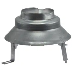
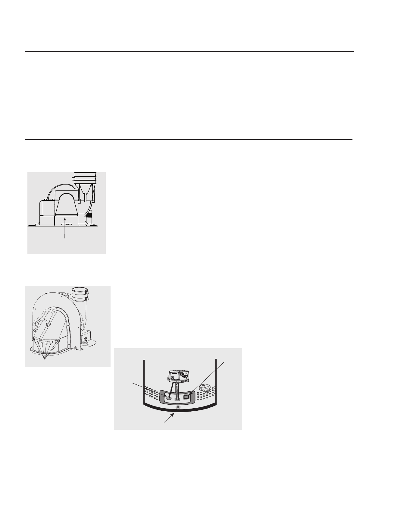
Blower Assembly Installation
Connect.blower.assembly.with.the.electrical.connector.Attach.
Blower.Assembly.to.top.pan.using.the.six.(6).screws.provided.
(See.diagram.to.the.left).Install.rubber.coupling.(supplied.in.
the.box.with.water.heater).on.blower.housing.and.secure.it..
Do not overtighten screws to ensure plastic does not crack.
NOTICE:..The.Blower.Assembly.is.model.specific.and.only.
the.blower.assembly.supplied.should.be.used.on.this.water.
heater
Additional installation information for The
Commonwealth of Massachusetts is located
on the back page of this manual.
Flue
Baffle
Rubber
Coupling
Blower
Assembly
13
Maximum and Minimum Vent Lengths for Residential
40 & 50 Gallon Power Vents
NOTICE: The mixing of 2" and
3" vent pipe is not recommended.
If 3" pipe is used, a 2" to 3"
reducer fitting is recommended at
the rubber coupling.
This.water.heater.is.supplied.with.
a.two-inch.Schedule.40.PVC.45°.
vent.terminal..When.venting.with.
3".pipe,.a.Schedule.40.PVC.45°.vent.
terminal.must.be.used.Screens.for.
both.2".and.3".vent.terminals.have.
been.included
Models
Maximum
Altitude for
2” & 3” Vents
43VP40SE2,.
43VP40SPE2,
43VP50SE2,.
43VP50SPE2
5,999’
43VP40E2,.
43VP40PE2,
43VP50E2,.
43VP50PE2
7,700’
Minimum Vent Restrictor
Vent.Pipe
Mesh
Vent.Restrictor
Vent.Terminal
Install.the.vent.restrictor.at.the.minimum.vent.lengths.
listed.above
DO NOT use.the.vent.restrictor.for.any.other.vent.
lengths
Number.of.
90°.elbows.
with.Vent
Number.of
45°.Elbows
Maximum.Vent.Pipe.
Length.in.Feet.(ft)
0’.-.2,000’
Maximum.Vent.Pipe.
Length.in.Feet.(ft)
2,001’.and.above
.
See.Maximum.Altitude.
chart.on.left
0-Maximum.Altitude:.See.chart.on.upper.left
One.(1) None 95’ 75’
One.(1) One.(1) 925’ 725’
Two.(2) None 90’ 70’
Two.(2) One.(1) 875’ 675’
Three.(3) None 85’ 65’
Three.(3) One.(1) 825’ 625’
Four.(4) None 80’ 60’
Four.(4) One.(1) 775’ 575’
Five.(5) None 75’ 55’
**.For.the.3”.vent,.one.90°.elbow.is.approximately.equal.to.5.feet.of.vent.
pipe..One.45°.elbow.is.approximately.equal.to.25.feet.of.vent.pipe
Minimum vent length for 3” vent pipe is one (1) foot of vertical pipe, one
(1) 90°elbow, and four (4) feet of horizontal pipe.
Maximum Venting information for 3” Vents**
Maximum Venting information for 2” Vents*
*.For.the.2”.vent,.one.90°.elbow.is.approximately.equal.to.6.feet.of.vent.pipe..
One.45°.elbow.is.approximately.equal.to.3.feet.of.vent.pipe
Minimum vent length for 2”vent pipe is one (1) foot (30.4 cm)of vertical
pipe, one (1) 90°elbow, and three (3) feet (0.91 m) of horizontal pipe.
Number.of.
90°.elbows.
with.Vent
Number.
of
45°.
Elbows
Maximum.Vent.
Pipe.Length.in.
Feet.(ft)
0’.-.2,000’
Maximum.Vent.Pipe.
Length.in.Feet.(ft)
2,001’.and.above
.
See.Maximum.
Altitude.chart.on.left
One.(1) None
44’ 24’
One.(1) One.(1)
41’ 21’
Two.(2) None
38’ 18’
Two.(2) One.(1)
35’ 15’
Three.(3)
None
32’ 12’
14
Installing the water heater.
Additional Considerations
..Do.Not.install.vent.terminal.under.any.patio.or.deck
..To.help.prevent.moisture.from.freezing.on.walls.and.under.
eaves,.do.not.locate.vent.terminal.on.the.side.of.a.build.ing.
with.prevailing.winter.winds
..When.terminating.the.vent.pipe.through.brick.or.masonry.
surfaces,.a.rust-resistant.sheet.metal.backing.plate..
behind.the.vent.termination.is.recommended.
(See.illustration)
..Do.Not.locate.vent.terminal.too.close.to.shrubbery,.as.flue.
gasses.may.damage.them
..Caulk.all.cracks,.seams.and.joints.within.six.(6).feet.of.vent.
terminal
..All.painted.surfaces.should.be.primed.to.lessen.the.chance.of.
physical.damage.Painted.surfaces.will.require.maintenance
..Insulate.vent.pipe.exposed.to.cold.conditions.(attics,.crawl.
spaces,.etc).with.inflammable.material.to.help.prevent.
moisture.from.accumulating.in.vent.pipe
..Do.Not.extend.exposed.vent.pipe.outside.of.building
If soffit vent is too
close, block off and
install new vent at
another location
Inside
corner
Caulk
Caulk
Caulk
6' (1.83 m)
caulk
zone or to edge of
window etc., starting
within 6'
Rising moisture will
collect under eaves
4'
6' caulk zone
2 ft. sq. sheet metal plate on
brick or masonary surface is recomended.
6'
WARNING:.Moisture in the flue gas will condense as it
leaves the vent terminal. In cold weather this condensate can
freeze on the exterior wall, under the eaves and on
surrounding objects. Some discoloration to the exterior of
the building is to be expected. However, improper location
or installation can result in severe damage to the structure
or exterior finish of the building
Horizontal Vent Terminal Location
The.location.of.the.vent.terminal.depends.on.the.following.
minimum.clearances.and.considerations.(see.illustration):
..Vent.Terminal.must.be.at.least.twelve.(12).inches.above.
grade.level.and.above.normal..
snow.levels
..Vent.Terminal.must.be.at.least.four.(4).feet.below,.or.four.
(4).feet.horizontally.from.any.door,.operable.window,.soffit,.
under.eave.vent.or.gravity.air.inlet.to.the.building.or.other.
appliances,.or.from.gas.or.electric.meters.Do.not.locate.
vent.above.walkways,.doors,..windows,.air.inlets,.gas.or.
electric.meters.or.other.equipment
..Vent.Terminal.must.be.at.least.three.(3).feet.above.any.
forced.air.inlet.located.within.ten.(10).feet.Any.fresh.or.
make-up.air.inlet.such.as.for.a.dryer.or.furnace.area.is.
considered.to.be.a.forced.air.inlet
..Vent.Terminal.must.be.at.least.eighteen.(18).inches.from.an.
inside.corner.formed.by.two.exterior.walls
4'
4'
Soffit vents
18"
4'
4'
4'
18"
Electric
meter
Inside
corner
3' above
if within 10'
Fresh
air
intake
12" (Above grade/snow level)
window or vent
NOTICE: All pipe, fittings, solvent cement, primers and procedures must conform to American
National Standards Institute and American Society for Testing and Materials (ANSI/ASTM) standards.
2.ft.sq.sheet.metal.plate.on.brick.or.
masonry.surface.is.recommended
15
NOTICE: All pipe, fittings, solvent cement, primers and procedures must conform to American
National Standards Institute and American Society for Testing and Materials (ANSI/ASTM) standards.
Vertical Vent Installation
Once.the.vent.terminal.location.has.been.
determined,.make.a.hole.through.the.roof.
and.interior.ceiling.to.accommodate.the.
vent.pipe.
Complete.the.vent.pipe.installation.to.the.
water.heater's.vent.connector.fitting.on.the.
blower.outlet.
Support.vertical.or.horizontal.lengths.as.
previously.mentioned
Install.adequate.flashing.where.the.vent.
pipe.passes.through.the.roof.
Determine.the.vent.terminal.height.and.cut.
vent.pipe.accordingly.Refer.to.the.above.
section.for.proper.vent.terminal.height.
Connect.vent.elbow.onto.vertical.pipe.
through.roof
Connect.short.piece.of.vent.pipe.
(approximately.3".long).to.elbow,.then.
insert.1/2".mesh.metal.screen.into.terminal.
elbow.and.join.it.to.the.short.piece.of.vent.
pipe
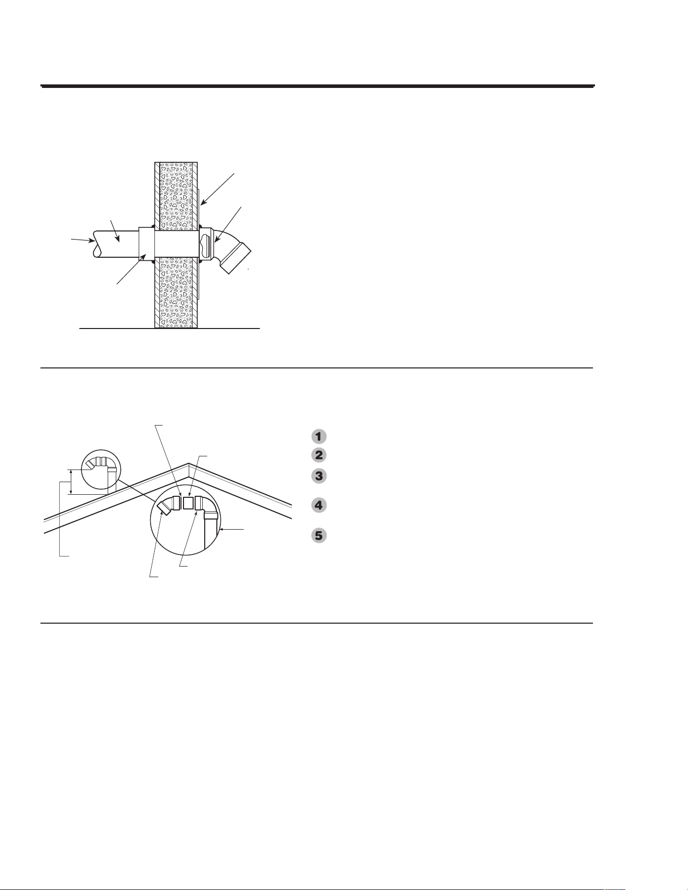
Vertical Vent Termination Location
The.location.of.the.vent.terminal.depends.on.the.following.
minimum.clearances.and.considerations.(see.illustration):
..Minimum..twelve.(12).inches.above.roof
..Minimum.twelve.(12).inches.above.anticipated.snow.level
..Maximum.twenty-four.(24).inches.above.roof.level.without.
additional.support.for.vent
..Four.(4).feet.from.any.gable,.dormer.or.other.roof.structure.
with.building.interior.access.(ie,.vent,.window,.etc)
..Ten.(10).feet.from.any.forced.air.inlet.to.the.building..Any.
fresh.or.make-up.air.inlet.such.as.a.dryer.or.furnace.area.is.
considered.to.be.a.forced.air.inlet
Short.Piece.of.Vent.Pipe
Min.12".Above.Roof.
Min.12".Above.
Anticipated.Snow.
Level
Max.24".Above.Roof.
(Without.Additional.
Support)
Insert.1/2".Mesh.Protective.
Screen.Inside.Terminal.Elbow
Vent.Pipe
Through..Roof
Elbow
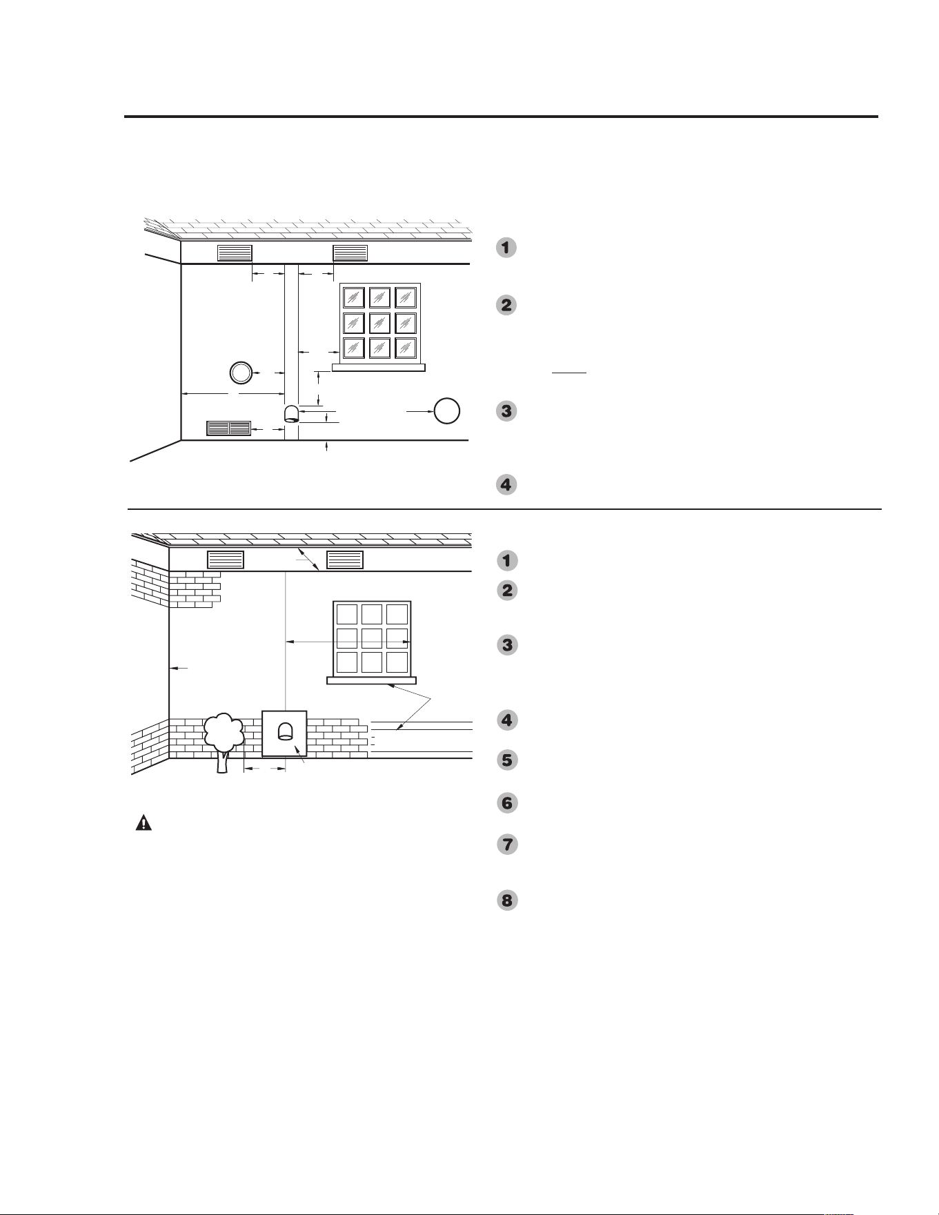
Horizontal Vent Installation
Once.the.vent.terminal.location.has.been.determined,.make.a.
hole.through.the.exterior.wall.to.accommodate.the.vent.pipe.
Vent.pipe.must.exit.exterior.wall.horizontally.only.
Insert.a.small.length.of.vent.pipe.through.the.wall.and.connect.
the.coupling.as.shown.to.the.left.
Place.the.1/2".mesh.metal.screen.inside.the.terminal.fitting.
and.connect.it.as.shown.to.the.vent.pipe.on.the.exterior.of.the.
building
Complete.the.rest.of.the.vent.pipe.installation.to.the.water.
heater's.vent.connector.fitting.on.the.blower.outlet.
If.necessary.support.horizontal.run.as.previously.mentioned
2'.x.2'.Sheet.
Metal.Shieldon.
Brick.or.Masonry.
Walls
Outside.of
Building.Wall
From
Water.Heater
Vent.Pipe
Pipe.Coupling..
.Vent.Terminal.
with.
1
/
2
".Mesh.
Protective..Screen.
Inside
Vent.Terminal
16
Installing the water heater.
All.joints.in.the.vent.piping.must.be.
properly.sealed.and.the.following.
materials.are.recommended:
PVC.materials.should.use.ASTM.D2564.
grade.cement
CPVC.materials.should.use.ASTM.F493.
grade.cement
ABS.materials.should.use.ASTM.D2235.
grade.cement
Cleaner-Primer.and.Medium.Body.Solvent.
Cement:
..Cut.pipe.end.square,.remove.jagged.
edges.and.burrs.Chamfer.end.of.pipe,.
then.clean.fitting.socket.and.pipe.joint.
area.of.all.dirt,.grease.or.moisture
..After.checking.pipe.and.socket.for.
proper.fit,.wipe.socket.and.pipe.with.
cleaner-primer.Apply.a.liberal.coat.of.
primer.to.inside.surface.of.socket.and.
outside.of.pipe.Do.not.allow.primer.to.
dry.before.applying.cement
..Apply.a.thin.coat.of.cement.evenly.in.
the.socket.quickly.apply.a.heavy.coat.
of.cement.to.the.pipe.end.and.insert.
pipe.into.fitting.with.a.slight.twisting.
motion.until.it.bottoms.out
NOTICE:.Cement.must.be.fluid;.if.not,.
recoat
..Hold.the.pipe.fitting.for.30.seconds.to.
prevent.the.tapered.socket.from.pushing.
the.pipe.out.of.the.fitting
..Wipe.all.excess.cement.from.the.joint.
with.a.rag.Allow.15.minutes.before.
handling.Cure.time.will.vary.according.
to.fit,.temperature.and.humidity
NOTICE: Stir the solvent cement
frequently while using. Use a natural
bristle brush or the dauber supplied
with the can. The proper brush size is
one inch.
NOTICE: This unit is equipped with a
Flammable Vapor Sensor. Do not apply
power until enough time has passed to
allow the vapors from the primer and
cement to dissipate.
Cementing Joints
WARNING: DANGER
OF FIRE OR BODILY
INJURY - Solvent cements
and primers are highly
flammable. Provide
adequate ventilation and do
not assemble near heat
source or open flame. Do not
smoke. Avoid skin or eye
contact. Observe all cautions
and warnings on material
containers.
CAUTION:
For proper installation:
DO NOT use solvent cement
that has become curdled,
lumpy or thickened.
DO NOT thin solvent
cement. Observe shelf
precautions printed on the
containers.
For applications below 32°F
use only low temperature
type solvent cement.
Appropriate solvent and
cleaner must be used for the
type of vent pipe used (PVC,
CPVC or ABS).
NOTICE: All pipe, fittings, solvent cement, primers and procedures must conform to American
National Standards Institute and American Society for Testing and Materials (ANSI/ASTM) standards.
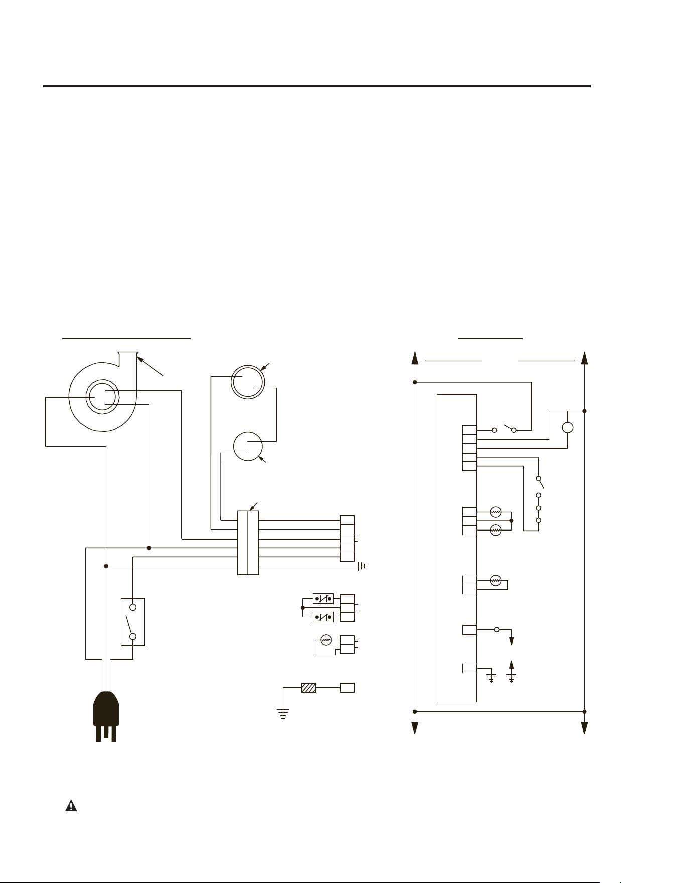
Diagram Without Optional Electronic Display
1
H
H
N
N
PRESSURE
SWITCH
TEMPERATURE
SWITCH
SPARK
P1
P3
P2
E1
GND
120
PILOT
ELECTRODE
ASSY
PS
TS
TS1
TS2
FV
MOT
1
2
3
4
5
1
2
3
1
1
2
SCHEMATIC
CONNECTION DIAGRAM
WV 4460E CONTROL
N
H
G
120 VAC
INDUCER
3 x 2 CONNECTOR
BL
R
Y
W
BK
G
5
4
3
2
1
<
>
BK = BLACK
BL = BLUE
G = GREEN
R = RED
W = WHITE
Y = YELLOW
1
2
W
W
TS2
BK
BK
TS1
FV
1
2
3
120 NEUT
GROUND
120 VAC
CAUTION!..Label.all.wires.prior.to.disconnection.when.servicing.controls.Wiring.errors.can.cause.improper.and.
dangerous.operation..VERIFY.PROPER.OPERATION.AFTER.SERVICING!
17
Wiring
If.local.codes.permit,.the.water.heater.may.
be.connected.to.electric.service.with.the.
power.cord.provided.(DO.NOT.use.an.
extension.cord).A.grounding.receptacle.is.
required
If.local.codes.do.not.permit.the.use.of.
cord.connections,.a.120.V,.50/60.Hz.
power.supply,.with.suitable.disconnecting.
means,.must.be.connected.to.the.black.and.
white.leads.in.the.heater.control.enclosure.
A.knock-out.hole.is.provided.to.permit.use.
of.conduit.or.metal-clad.cable.connectors.
The.maximum.current.draw.is.
approximately.50.amps.
The.water.heater.must.be.electrically.
grounded.in.accordance.with.local.
codes,.or,.in.the.absence.of.local.codes,.
in.accordance.with.latest.edition.of.the.
National.Electric.Code.ANSI/NFPA.No.
70.Refer.to.the.figures.below.for.water.
heater.internal.wiring
NOTE:.It.is.not.recommended.that.this.
unit.be.installed.on.a.GFCI.circuit
18
Installing the water heater.
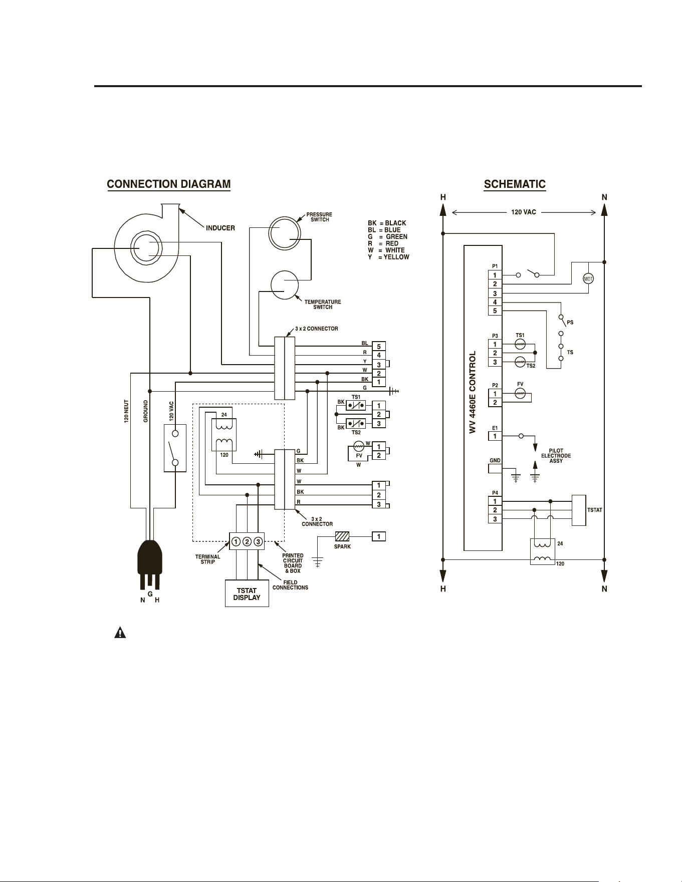
Diagram With Optional Electronic Display
CAUTION!..Label.all.wires.prior.to.disconnection.when.servicing.controls.Wiring.errors.can.cause.improper.and.
dangerous.operation..VERIFY.PROPER.OPERATION.AFTER.SERVICING!
19
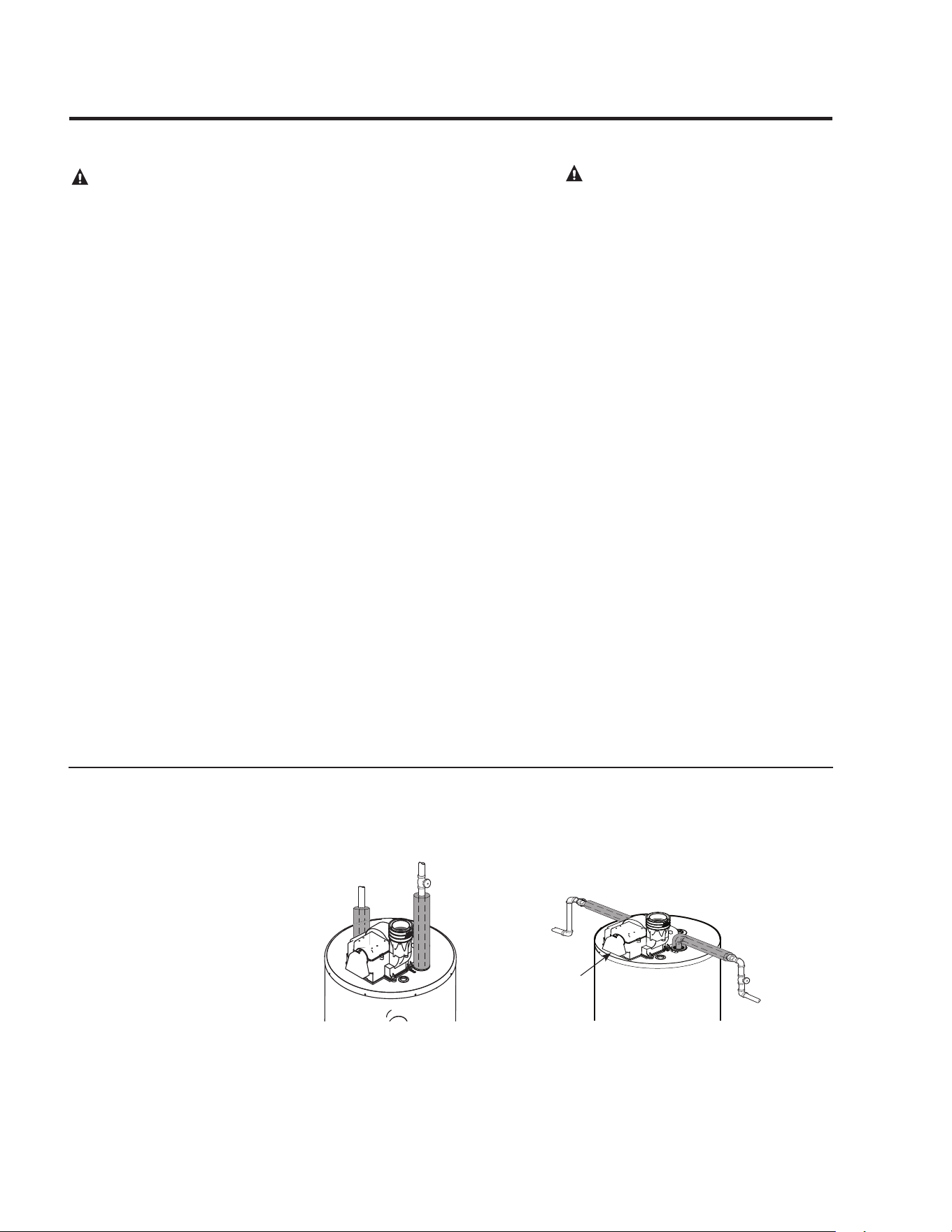
For.increased.energy.efficiency,.some.
water.heaters.have.been.supplied.with.
two.24”.sections.of.pipe.insulation.
Please.install.the.insulation,.according.
to.the.illustrations.above,.that.best.meets.
your.requirements
Hot and Cold Pipe Insulation Installation
Insulation Blankets
Insulation.blankets,.available.to.the.
general.public,.for.external.use.on.gas.
water.heaters.are.not.necessary..The.
purpose.of.an.insulation.blanket.is.to.
reduce.the.standby.heat.loss.encountered.
with.storage.tank.heaters..This.water.
heater.meets.or.exceeds.the.National.
Appliance.Energy.Conservation.Act.
standards.with.respect.to.insulation.and.
standby.loss.requirements.making.an.
insulation.blanket.unnecessary.
The.manufacturer’s.warranty.does.not.
cover.any.damage.or.defect.caused.by.
installation,.attachment.or.use.of..
any.type.of.energy.saving.or.other.
unapproved.devices.(other.than.those.
authorized.by.the.manufacturer).into,.onto.
or.in.conjunction.with.the.water.heater.
The.use.of.unauthorized.energy.saving.
devices.may.shorten.the.life.of.the.water.
heater.and.may.endanger.life.and.property
The.manufacturer.disclaims.any.
responsibility.for.such.loss.or.injury.
resulting.from.the.use.of.such.
unauthorized.devices
CAUTION: If local codes require the
application of an external insulation
blanket to this water heater, pay careful
attention to the following so as not to
restrict the proper function and
operation of the water heater:
●..Do.not.cover.the.operating.or.warning.
labels.attached.to.the.water.heater.or.
attempt.to.relocate.them.on.the.exterior.
of.insulation.blanket
..Do.not.apply.insulation.to.the.top.of.the.
water.heater.This.will.interfere.with.the.
safe.operation.of.the.blower.assembly
..Do.not.cover.the.burner.access.door,.
jacket.door,.gas.control.(thermostat)/gas.
valve.or.pressure.and.temperature.relief.
valve
..Do.not.apply.insulation.to.the.bottom.
of.the.water.heater.or.the.area.where.
the.combustion.air.inlet.openings.and.
Flammable.Vapor.Sensor.are.located.
This.area.must.be.unobstructed.so.as.
not.to.restrict.combustion.air.flow.to.
the.burner.or.operation.of.the.sensor
..Inspect.the.insulation.blanket.frequently.
making.certain.it.has.not.sagged.
and.it.is.not.restricting.the.air.flow.
to.the.combustion.air.inlet.openings.
(perforation.holes).or.the.Flammable.
Vapor.sensor.located.around.the.lower.
perimeter.of.the.water.heater.jacket.
This.could.result.in.an.unsafe.operating.
condition
WARNING: If local
codes require external
application of insulation
blanket kits the
manufacturer’s instructions
included with the kit must
be carefully followed.
NOTICE: If pipe
insulation is used, ensure
that the thickness does
not exceed ½”. Insulation
thicker than ½” can
interfere with the Blower
Assembly Dilution Air
Holes.
Dilution Air
Intake
Typical vertical piping arrangement
Typical horizontal piping arrangement
20
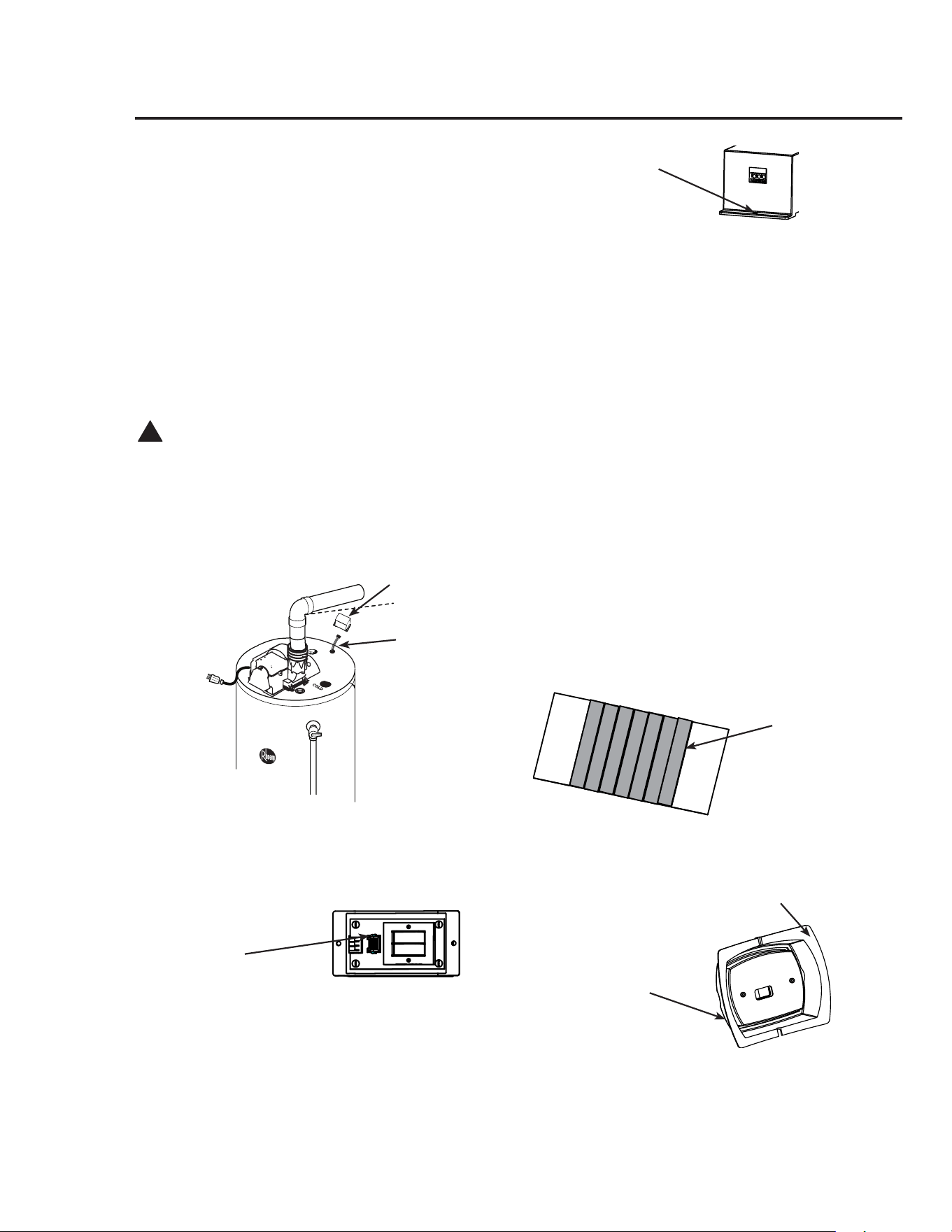
This.PowerVent.water.heater.contains.an.accessory.kit.for.
installing.the.User.Display
User.Display.Mounting.Kit.–.AS42461
. a...Optional.Water.Heater.Mounting.Bracket.–.
AP14752
. b..12.feet,.18.AWG.Thermostat.Wire.–.AP14820
. c..Optional.Mounting.Tape.–.AP14819
. d..Transformer.Enclosure.–.AP14875
. e...Screw,.#8.x.½".Self.Drilling.qty.2.AP5925GS
. f..User.Display.–.AP14697
Installation.Instructions:
!
CAUTION:..Turn.the.switch.on.the.blower.to.the.
“off”.position.and.disconnect.power.to.the.water.heater.
before.proceeding!
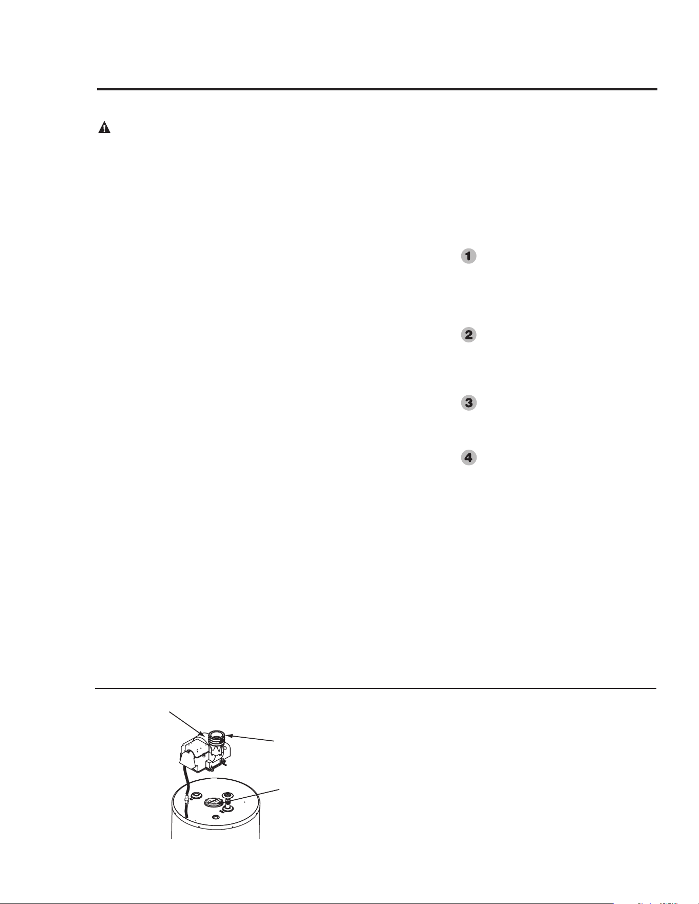
1...Locate.the.electrical.connection.for.the.Transformer.
Enclosure.on.the.top.of.the.water.heater..This.
electrical.connection.features.a.white.6-pin.plug.and.
white.heat.shrink
2...The.Transformer.Enclosure.features.a.6-pin.connection.
located.on.the.circuit.board.inside.the.enclosure..
Attach.the.top.pan.harness.connector.to.this.6-pin.
connector.in.the.correct.orientation
3...Locate.the.two.screw.pilot.holes.on.the.water.heater.
top.to.attach.the.Transformer.Enclosure.to.the.top.pan..
Position.the.enclosure.so.the.terminal.strip.opening.
is.visible.from.the.front.of.the.water.heater..Secure.
enclosure.to.top.pan.with.screws.provided.in.the.User.
Display.Mounting.Kit.without.pinching.any.wires
NOTICE: Do not over tighten to avoid cracking
plastic enclosure.
4...Determine.where.the.User.Display.will.be.located..
The.display.can.be.attached.to.the.water.heater.jacket.
with.supplied.Water.Heater.Mounting.Bracket.or.
mounted.remotely.to.a.wall.via.the.wall.plate.up.to.100.
feet.away.using.18.AWG.solid.copper.thermostat.wire..
Any.installation.location.over.12.feet.from.the.water.
heater.will.require.additional.thermostat.wire..(Not.
supplied)
5...If.remote.mounting,.go.to.step.19
6...Cut.enough.thermostat.wire.from.the.12.feet.
provided.to.connect.the.front.mounted.display.to.the.
Transformer.Enclosure.located.on.the.top.pan
7...Strip.½”.insulation.from.the.3.wires.on.both.ends..
The.wire.provided.is.standard.3-wire.with.the.colors.
GREEN,.RED.and.WHITE
8...Connect.one.end.of.the.wire.to.the.Transformer.
Enclosure.spring.terminal.strip..From.left.to.right.
colors.shall.be.GREEN.–.RED.–.WHITE..Wires.
should.easily.insert.into.the.terminal.strip..If.required.
for.wire.insertion.or.removal,.use.small.flat.blade.
screw.driver.to.press.the.tab.located.below.each.wire.
hole
9...Remove.two.strips.of.Display.Mounting.Tape.and.
attach.to.the.inside.flanges.of.the.Water.Heater.
Mounting.Bracket
Installing the Optional User Display
Transformer
Pin.Plug
6.Pin.Connection.for.to.
Circuit.Board
Mounting.Holes.for.
Transformer
Display.Mounting.
Tape.Strips
Water.Heater.
Mounting.Braket.
for.Display
Flange.of.Mounting.
Bracket
11...The.Water.Heater.Mounting.Bracket.features.a.
wiring.slot.on.the.top.flange.and.an.opening.for.the.
wire..Pass.the.thermostat.wire.though.the.Water.
Heater.Mounting.Bracket.opening
12...Clean.any.dust.or.dirt.from.water.heater.jacket.to.
allow.proper.tape.adhesion
13...Remove.tape.backing.and.carefully.attach.to.the.
heater.jacket.above.the.Rheem.logo..Allow.the.
thermostat.wire.to.be.positioned.in.the.wire.slot.
located.on.the.bracket.top.flange
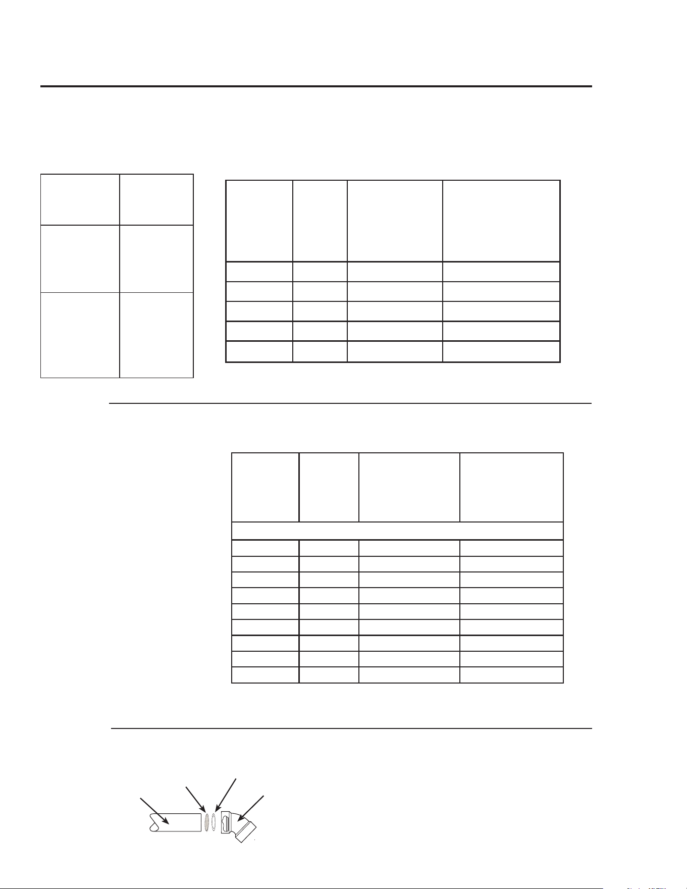
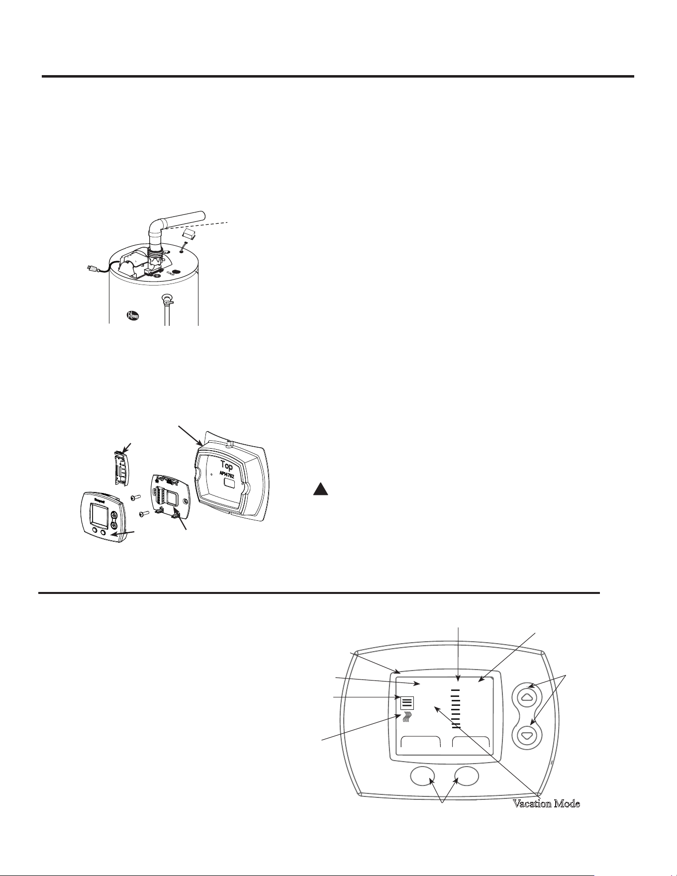
14...The.User.Display.will.be.mounted.to.the.plastic.
Water.Heater.Mounting.Bracket
15...Separate.wall.plate.from.the.User.Display.by.
removing.battery.cover.and.carefully.pull.wall.plate.
from.display
NOTICE: The battery backup option is not available
on this model.
16...Replace.battery.cover..
17...Attach.display.wall.plate.to.heater.bracket.using.
the.two.#6.x.½”.Type.A.screws.provided.in.User.
Display.Mounting.Kit..Wire.should.pass.through.
display.wall.plate.opening
18...GO.TO.STEP.27
19...Remote.mounting.will.not.require.the.Display.to.
Heater.Bracket.or.Display.Mounting.Tape..The.
bracket.may.be.kept.for.future.use.or.recycled.
20...Choose.mounting.location.and.route.thermostat.wire.
to.this.location
21...Separate.wall.plate.from.the.User.Display.by.
removing.battery.cover.and.carefully.pull.wall.plate.
from.display
22...Replace.battery.cover
23...Pass.thermostat.wire.through.wire.hole.in.wall.plate
24...Use.mounting.holes.on.wall.plate.to.mark.wall.hole.
locations
25...Drill.3/16”.holes.and.install.wall.anchors.if.required
26...Use.two.#6.x.1”.Type.A.screws.provided.in.the.User.
Display.box.to.attach.wall.plate.to.surface
27...Connect.thermostat.wire.to.wall.plate.as.follows:
. •...Top.Terminal.-.GREEN.-.Data.
Communication
. •...Middle.Terminal.-.RED.-.Power
. •...Bottom.Terminal.-.WHITE.-.Common
28...Attach.Thermostat.Display.to.wall.plate
!
ATTENTION: Leave peel off screen protector on
the User Display for customer to review and remove.
30...Connect.power.to.water.heater
31...Turn.on.water.heater.and.allow.to.heat
32...Check.thermostat.display.for.proper.display.and.
function.
Installing.the.Optional.User.Display
21
User.
Display
Battery.
Cover
User.Display.
Mounting.Bracket
Water.Heater.
.Mounting.Bracket
Your.water.heater.includes.a.user.display.for.easy.
local.or.remote.water.heater.programming..The.
user.display.features:
. •..Water.heater.temperature.setpoint.control
. •...Large,.clear,.backlit.display.is.easy.to.read-
even.in.the.dark
. •..Displays.relative.available.hot.water
. •..Service.needed.indicator
User Display Features
Caution: Risk of Scalding
Increases with Hotter Water
Est. Hot SERVICE
Water NEEDED
Very Hot
C
B
A
Hot
•
•
•
Low
Max Setting
Clear ModeDone Mute
Error
88
ON
VAC
Heat
Up/Down
Keys
Vacation.Mode
Left/Right.Keys
Heat
Indication
Hot.Water
Availability
Error.
Code
Scald.
Warning
Setpoint.Temperature
Max.Setpoint.
Temperature
Water.Heater.Optional.User.Display.-.Operation.Instructions
22
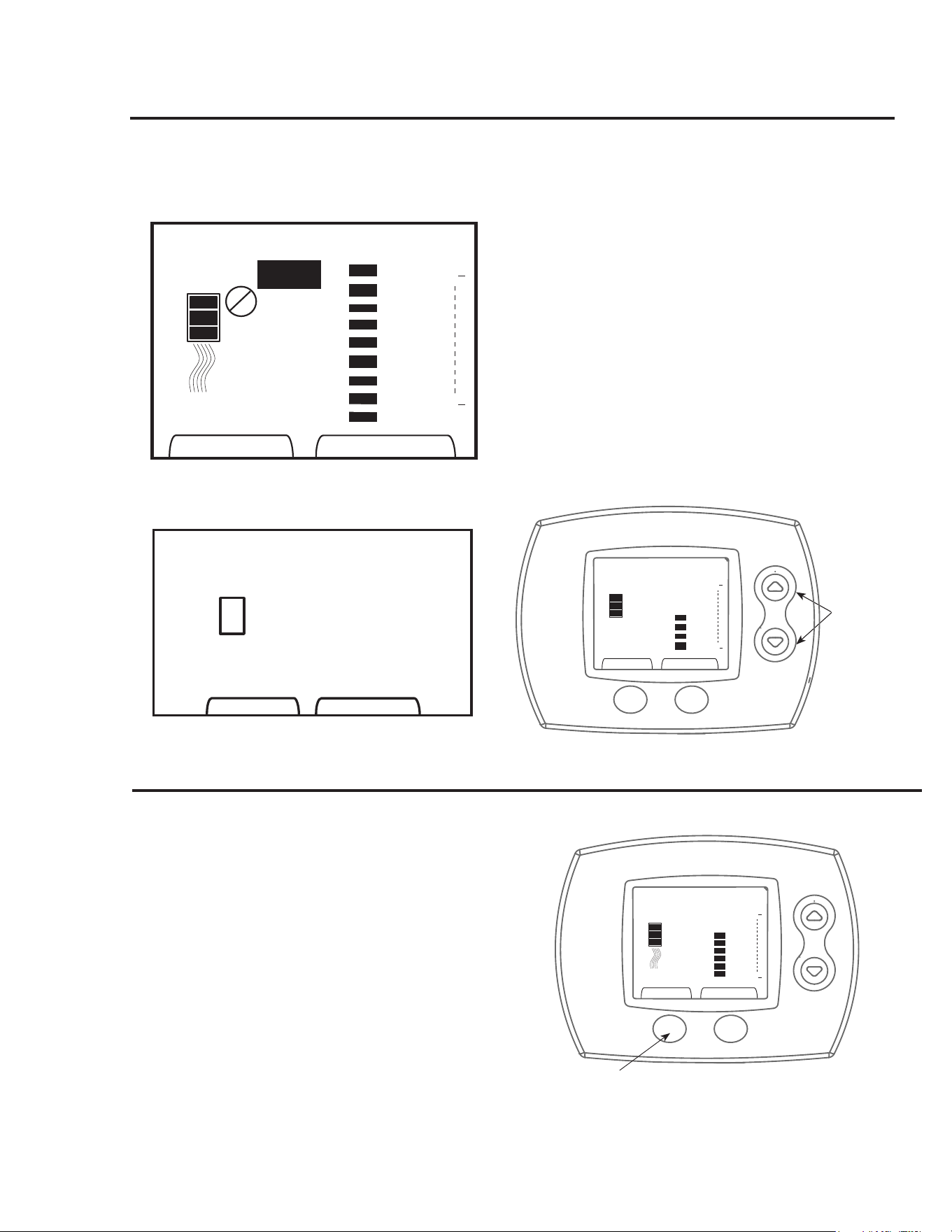
After.power.on,.all.segments.on.the.LCD.will.be.displayed.
for.2.seconds,.(See.Diagram.A).followed.by.software.
revision.shown.for.2.seconds.(See.Diagram.B)
User.Mode.is.entered.after.all.required.data.is.received.
from.the.appliance.when.powered-up.The.display.shows.
temperature.setpoint,.estimated.amount.of.hot.water.and.
maximum.temperature.setpoint.Heat.symbol.is.turned.on.
when.heating.cycle.is.active.Scald.warning.starts.flashing.
whenever.the.adjusted.setpoint.exceeds.the.“Hot”.setting.
and.becomes.solid.after.30.seconds.of.flashing
Unlocking the User Display
The.user.display.includes.a.display.lock.that.will.prevent.
accidental.adjustments.to.the.water.heater..To.unlock.the.
display,.hold.down.the.UP.and.DOWN.arrow.buttons.until.
the.lock.icon.flashes.and.disappears..The.display.can.now.
be.adjusted..The.display.will.automatically.relock.if.no.
button.presses.are.detected.within.a.60.second.period
C A U T I O N : R i s k o f S c a l d i n g
I n c r e a s e s w i t h H o t t e r W a t e r
Heat
Very Hot
C
B
A
Hot
•
•
•
Low
Max Setting
SERVICE
NEEDED
Error
88
ON
VAC
HI DEMAND
Est. Hot
Water
Done Mute
Clear Mode
25
ON
Est. Hot
Water
Very Hot
C
B
A
Hot
•
•
•
Low
Up/Down
Keys
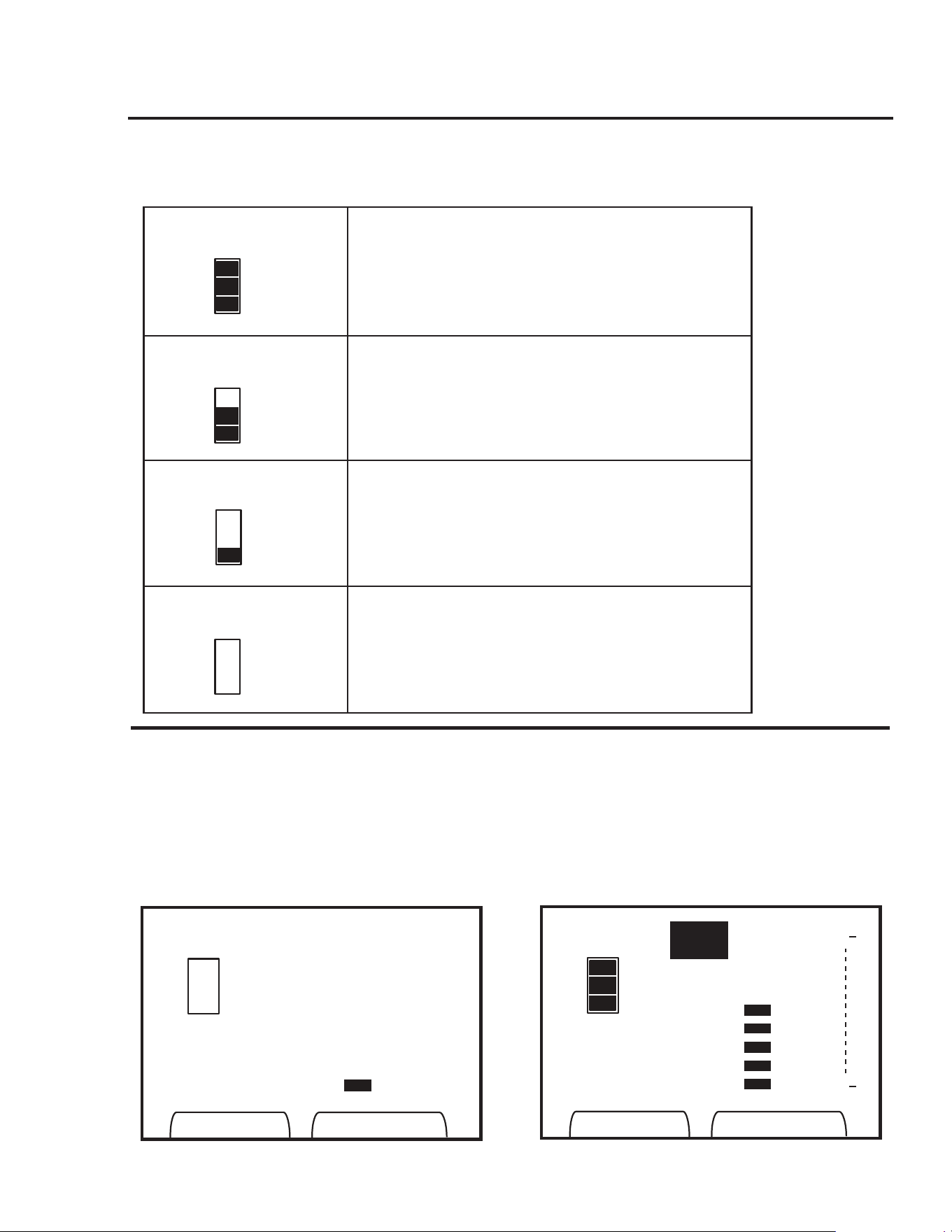
Display Temperature Setting Limits
Display Temperature Setting
Water.heater.setpoint.temperature.is.shown.using.vertical.
bars.on.the.display.The.more.bars.shown.the.higher.the.
setpoint.temperature.Use.the.UP.or.DOWN.arrows.to.
select.the.desired.setpoint.temperature.The.top.bar.indi-
cates.the.water.heater.setpoint..The.picture.below.shows.
a.setpoint.of.“A”
Notice:..When.the.temperature.is.set.above."HOT",.the.
display.will.show.the."Risk.of.Scalding.Caution"
When.the.desired.setpoint.is.shown.on.the.display,.press.
the."Done".button.below.the.display.The.user.display.will.
then.lock.to.prevent.accidental.adjustments
ON
Est. Hot
Water
Very Hot
C
B
A
Hot
•
•
•
Low
C A UT I ON : R i sk of S c a l d i n g
I n c re a s es w i t h H o tt er W a te r
Heat
Done
Mode
Done.Button
Diagram.A
Diagram.B
23
Water Heater Optional User Display - Operation Instructions
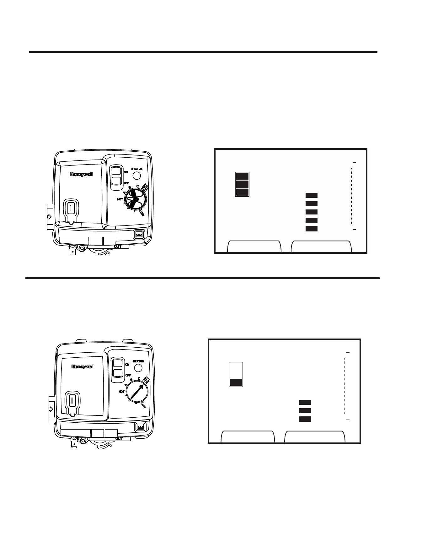
Display Temperature Setting Limits
The.user.display.setpoint.temperature.cannot.exceed.maxi-
mum.water.heater.valve.setpoint.temperature.at.any.time.
Max.Setting.icon.appears.when.the.user.display.setpoint.
exceeds.the.water.heater.gas.valve.knob.setpoint
The.water.heater.gas.valve.knob.below.is.set.to.HOT.there-
fore.the.user.display.shows.Hot.as.the.maximum.available.
setpoint.The.customer.in.this.example.has.chosen.to.set.
the.temperature.to.Hot..When.the.user.display.is.set.to.the.
maximum.available.setpoint,.the.Max.Setting.message.will.
appear.on.the.user.display
ON
Est. Hot
Water
Very Hot
C
B
A
Hot
•
•
•
Low
Max Setting
ON
Est. Hot
Water
Very Hot
C
B
A
Hot
•
•
•
Low
The.water.heater.gas.valve.knob.below.is.set.to.VERY.HOT.
therefore.the.user.display.shows.Very.Hot.as.the.maximum.
available.setpoint..The.customer.in.this.example.has.chosen.
to.set.the.temperature.between.Low.and.Hot..With.this.gas.
valve.knob.setting,.the.full.range.of.temperature.setpoints.is.
available.at.the.user.display
See.Figure.on.left.below
User.Display
User.Display
Water.Heater.Gas.Valve
Water.Heater.Gas.Valve
24
Three.bars.shown.on.the.user.display.are.an.estimate.of.hot.water.
available.relative.to.the.temperature.setpoint..The.chart.below.
describes.what.each.symbol.means.
Tank.is.full.of.hot.water
Two.thirds.of.the.tank.volume.available
One.third.of.the.tank.volume.available
No.hot.water.available
Est. Hot
Water
Est. Hot
Water
Est. Hot
Water
Est. Hot
Water
VAC
Est. Hot
Water
Very Hot
C
B
A
Hot
•
•
•
Low
Mode
The.user.display.features.a.vacation.mode.which.sets.the.
water.heater.temperature.to.Low..The.user.display.toggles.
between.On.and.Vacation.Modes.when.“Mode”.key.is.
pressed.Note.that.the.Estimated.Hot.Water.symbol.shows.
no.hot.water.available.when.in.VAC.mode..To.return.the.
water.heater.to.normal.“ON”.mode,.unlock.the.display.and.
press.the.Mode.button
Vacation.Mode
Estimated.Hot.Water
Error.Display
When.an.error.message.is.received.from.the.water.
heater,.the."SERVICE.NEEDED".icon.flashes.See.
the.screen.example.below..Call.your.water.heater.
contractor
ON
Est. Hot
Water
Very Hot
C
B
A
Hot
•
•
•
Low
Service
Needed
Installing the water heater continued.....
25
DO
. ❑. DO.check.inlet.gas.pressure.to.ensure.that.
it.is.within.the.range.specified.on.the.rating.
plate
. ❑.DO.provide.adequate.air.for.combustion.
and.ventilation.as.discussed.in.the.Use.and.
Care. Manual. and. the. National. Fuel. Gas.
Code
. ❑.DO. maintain. proper. clearances. to.
combustibles.as.specified.on.the.rating.plate
. ❑.DO.allow. enough. time. for.joint. cement.
vapors. to. dissipate. BEFORE. applying..
power.to.the.water.heater
. ❑.DO. ensure. that. the. venting. system.
complies. with. the. guidelines. found. in. the.
Use.and.Care.Manual.and.National.Fuel.Gas.
Code
. ❑.DO.contact.a.qualified.service.technician.
if.the.main.burner.will.not.stay.lit..The.burner.
chamber.is.designed.to.be.sealed.utilizing.a.
gasket.and.tamper.resistant.screws
DON’T
. ❑.DON’T. block. or. restrict. Combustion.
Air.Inlet.Openings.or.the.Flammable.Vapor.
Sensor. located. around. the. lower. portion. of.
the.water.heater.jacket
. ❑.DON’T. block. or. restrict. the. Blower.
Assembly.Dilution.Air.holes.(see.diagram.to.
the.left)
. ❑.DON’T.remove.the.Burner.Access.Door.
unless.absolutely.necessary..This.should.only.
be.done.by.a.qualified.service.technician..A.
new. burner. access. door. gasket. must. be.
installed.on.any.burner.access.door.that.has.
been.removed
. ❑ DON’T. install. this. water. heater. where.
standing.water.may.occur..The.base.of.the.
water.heater.is.meant.to.be.mounted.on.a.dry.
surface
. .❑.DON’T.allow.cleaners,.solvents,.or.other.
materials. to. come. into. contact. with. the.
Flammable.Vapor.Sensor
. .❑.DON’T. operate. the. water. heater. if. the.
sight.glass.or.burner.access.door.grommet.is.
damaged.or.broken.(see.to.the.left)
During Installation of this water heater...........
Heat Traps
For.increased.energy.efficiency,.some.
water.heaters.have.been.supplied.with.
factory.installed.3/4”.NPT.heat.traps..in.
the.hot.outlet.line.and.cold.water.inlet.
line
These.heat.traps.may.require.a.minimum.
of.one.(1).90°.3/4”.NPT.elbow.and.may.
require.an.additional.90°.3/4”.NPT.elbow.
or.a.3/4”.coupling.depending.on.your.
installation.needs..See.Illustration.of.
nipples.and.heat.traps.on.page.33
Sight.Glass
Flammable.
Vapor.Sensor
Burner.Access.
Door.Grommet
Dilution Air Inlet
Tall Models
Blower Assembly Dilution Air Holes
Short.Models.

Installation Checklist
A. Water Heater Location
B. Water Supply
C. Gas Supply
D. Relief Valve
E. Venting
❑ Close.to.area.of.vent
. ❑ Indoors.and.protected.from.freezing.. .
.. temperatures
. ❑ Proper.clearance.from.combustible.surfaces..
.. observed.and.water.heater.not.installed.on...
.. carpeted.floor
. ❑ Sufficient.fresh.air.supply.for.proper.. .
.. operation.of.water.heater
. ❑ Air.supply.free.of.corrosive.elements.and...
.. flammable.vapors
. ❑ Provisions.made.to.protect.area.from.water..
.. damage
. ❑ Sufficient.room.to.service.heater
. ❑ Combustible.materials,.such.as.clothing,.. .
.. cleaning.materials,.rags,.etc.clear.of.the.. .
.. base.of.the.heater
. .❑ Clearances.of.1”.from.combustion.air.
. .. inlet.openings.observed
. .❑ Flammable.vapor.sensor.is.not.blocked
❑ Water.heater.completely.filled.with.water
. ❑ Air.purged.from.water.heater.and.piping
.
❑ Water.connections.tight.and.free.of.leaks
❑ Gas.line.equipped.with.shut-off.valve,.union..
.. and.sediment.trap
.
. ❑ Approved.pipe.joint.compound.used
. ❑ Soap.and.water.solution.used.to.check.all. .
... connections.and.fittings.for.possible.gas.. .
.. leak
. ❑ Gas.Company.inspected.installation.(if.. .
.. required)
❑ Temperature.and.Pressure.Relief.Valve.. .
.. properly.installed.and.discharge.line.run.to..
.. open.drain
❑ Discharge.line.protected.from.freezing
. ❑ Heater. vented. separately. from. all. other.
appliances
❑ Flue. baffle. properly. hung. in. top. of. heater’s..
.. flue
. ❑ Blower.assembly.properly.installed
. ❑. .Proper.materials.and.techniques.used.in.vent.
assembly
. ❑. .Vent.pipe.properly.secured.to.blower.housing
.
❑. Vent.pipe.supported.at.required.intervals
. ❑. Appropriate.minimum.clearances.observed
. ❑. .Precautions.taken.to.prevent.moisture.damage.
around.vent.termination
❑ Vapors. from. vent. pipe. cement. and. primer.
have. dissipated. prior. to. applying. electrical.
power
F. Wiring
❑ Correct.power.supply.(120.V)
. ❑ Electrical.connections.tight
.
❑ Heater.properly.grounded.and.proper.polarity.
observed
26
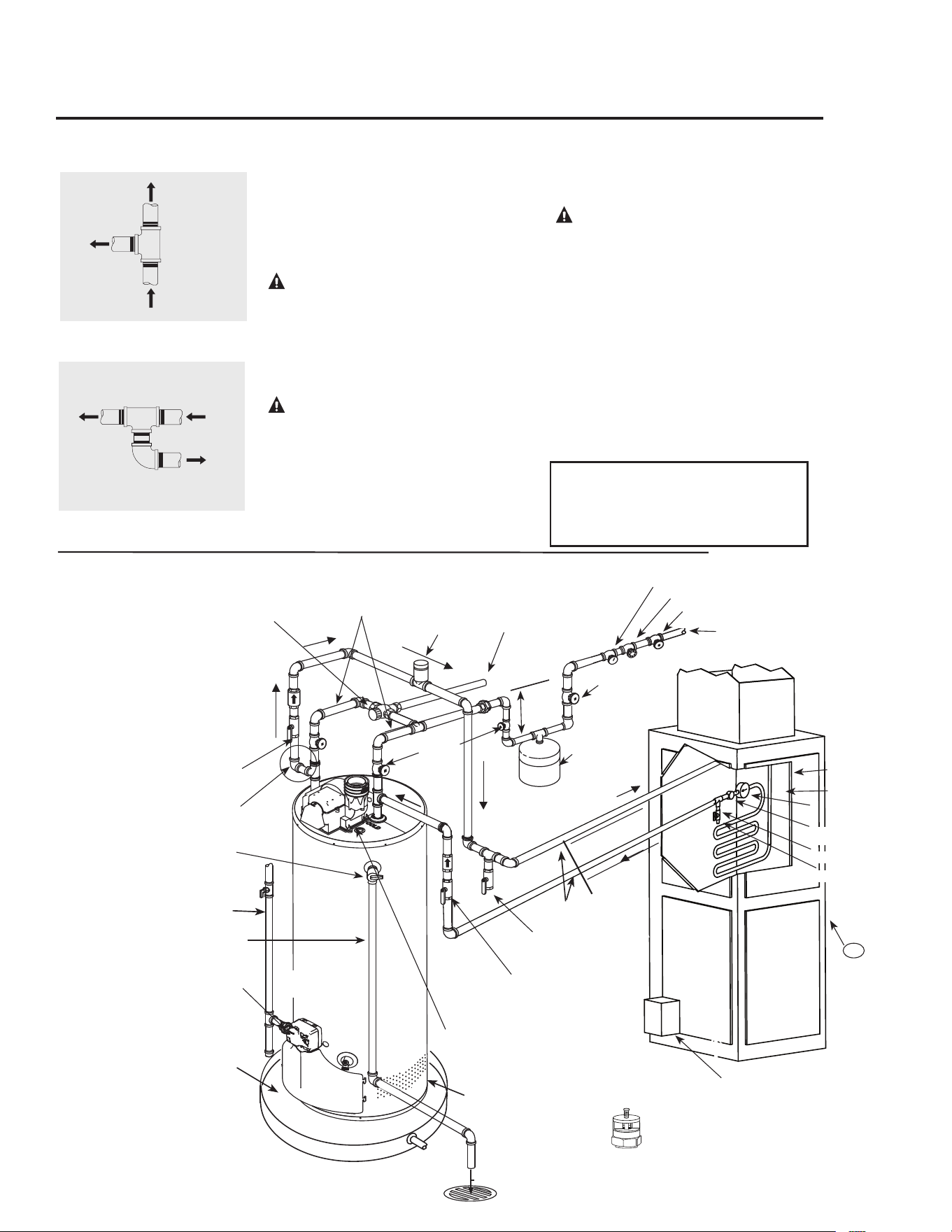
Tee fitting for vertical hot
water supply lines.
Hot water
supply to
house
From HOT
outlet on
water heater
Hot water
supply to
heating
unit
Supplemental instructions for gas water heaters installed
in potable water/space heating applications.
Local codes or plumbing authority requirements may vary from the instructions or diagrams provided
in this manual and take precedent over these instructions.
Tee fitting for horizontal hot
water supply lines.
From HOT
outlet on
water heater
Hot water
supply to
house
Hot water supply
to heating unit
Combination Potable Water and Space Heating Application
Tee.fitting.must.be.installed.as.shown.
This.ensures.that.any.air.in.the.water.lines.
will.be.purged.through.the.domestic.water.
faucets.and.showers
DANGER: When this system
requires water for space heating at
elevated temperatures (above 125°F
[52°C.]), a mixing or tempering valve
must be installed in the hot water
supply line to the house in order to
reduce the scald hazard potential.
DANGER: Any piping or components
used in the installation of this water
heater in a combination potable and
space heating application must be
suitable for use with drinking water.
DANGER: If this water heater is
installed in an application intended to
supply domestic hot water needs and
hot water for space heating purposes,
do not connect the heater to an existing
heating unit or components of a heating
system that have previously been used
with a non drinking water system. Toxic
chemicals such as those used for boiler
treatment may be present and will
contaminate the drinking water supply
causing possible health risks. Never
introduce toxic chemicals, such as those
used for boiler treatment, into this
system.
Notice:..50'.-.0".maximum.distance.
from.water.heater.to.fan.coil.
(developed.length).is.required.for.
Massachusetts.State
27
Typical Piping Diagram for Combination Potable/Space Heating Installation
Spring.loaded.check.valve.in.heating.unit.
hot.water.supply.line.and.cold.water.return.
line.(not.supplied.with.water.heater)
NOTE:.This.check.valve.is.incorporated.
in.some.heating.units.Refer.to.the.
installation.instructions.supplied.with.
specific.heating.unit.to.determine.if.it.is.
required
All.water.piping.shall.be.insulated.in.
accordance.with.Local.and.State.Energy.
Code
Isolation.valve.in.
cold.water.return.line.
from.heating.unit.(not.
supplied.with.water.
heater)
Nominal.3/4".size.mixing.or.tempering.valve.
(refer.to.warning.above)..Follow.mixing.or.
tempering.valve.manufacturer’s.instructions.for.
installation.of.the.valve
Temperature.and.pressure.relief.
valve.discharge.line
Air.Handler
Drain.valve
(not.supplied.with
.water.heater)
Hot.water..
to.space.heater
Temperature.and.Pressure.Relief.
Valve,.tie.to.location.approved.by.
local.code
See.diagrams.above.for.proper..
pipe.application.for.vertical..
or.horizontal.supply.lines
Isolation.valve.in.hot.water.supply.line.
to.heating.unit.(not.supplied.with.water.
heater)
3/4".cold.water.supply
3/4".Tempered.
domestic.hot.water.
supply.to.house
Gas.line.to.water.heater
6”.Air.Gap
Combustion.Air.Inlet.
Openings
2.Gallon.Thermal.
Expansion.Tank.
(if.required-not.
supplied.with.
water.heater)
Air.vent
Heat.Trap
6”.Min
3/4".Shut-Off.Valve.(Typ)
3/4".Check.Valve.with.1/8".Hole
Pressure.Gauge
3/4".Shut-Off.Valve.(Typ)
3/4".Shut-
Off.Valve.
(Typ)
Hot.water.coil
All.bronze.pump
Check.valve.
internal.in.pump
Air.bleed.valve
Water.Sample.Tap
.T
FAN
ON
OFF
HEAT
COOL
To.HVAC.Unit
Electronically.controlled.pump.timer..
Activates.every.6.hours.for.60.seconds..
Wire.to.bronze.pump
3/4".HWS.&.HWR.
to.Heating.Coil
Minimum.of.2'-0".developed.length.
of.3/4".pipe
Water.Heater.drain.pan.installed.in.
accordance.with.the.Local.and.State.
Code
Water.Heater.to.be.in.accordance.with.
the.Local.and.State.Energy.Code
Gas.Fired.
Water.Heater.
Gas.Direct.Vent.discharge.
must.comply.with.Local.
and.State.Codes
Vacuum Relief Valve
(Not Supplied)
If required, install per local codes
and valve manufacturer’s
instructions.
.120°.to.130°..
.........
140°..
Gas..Control.(Thermostat)
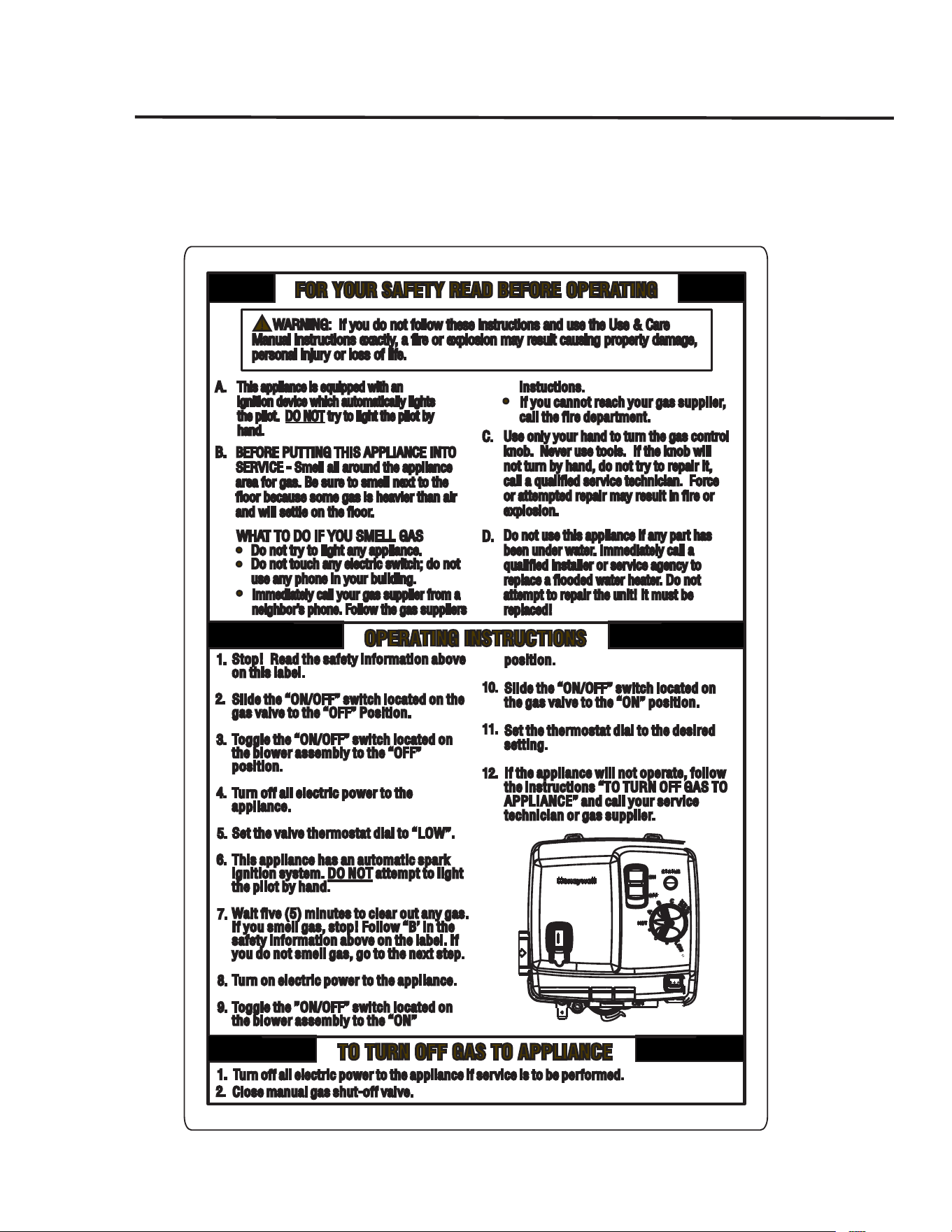
28
Lighting the water heater..
Before operating this water heater, be sure to read and follow the instructions on the label pictured
below and all other labels on the water heater, as well as the warnings printed in this manual. Failure
to do so can result in unsafe operation of the water heater resulting in property damage, personal
injury, or death. Should you have any problems reading or following the instructions in this manual,
STOP, and get help from a qualified person.
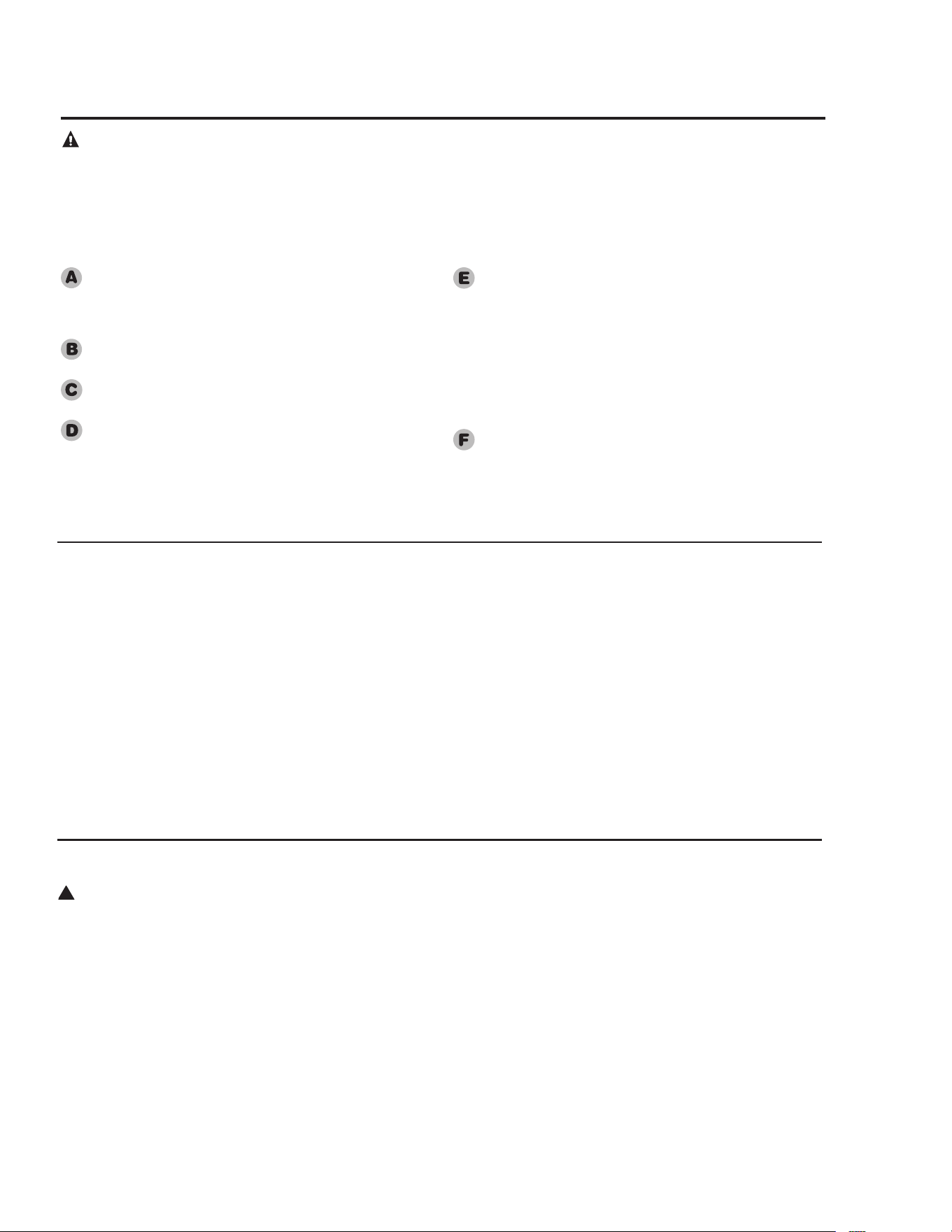
29
Safety.Precautions
...Do.turn.off.manual.gas.shut-off.valve.if.water.heater.
has.been.subjected.to.over.heating,.fire,.flood,.
physical.damage.or.if.the.gas.supply.fails..
to.shut.off
...Do.Not.turn.on.water.heater.unless.it.is.completely.
filled.with.water
...Do.Not.turn.on.water.heater.if.cold.water.supply.
shut-off.valve.is.closed
...Do.Not.allow.combustible.materials.such.as.
newspaper,.rags.or.mops.to.accumulate.near..
water.heater
...Do.Not.store.or.use.gasoline.or.other.flammable.
vapors.and.liquids,.such.as.adhesives.or.paint.thinner,.
in.vicinity.of.this.or.any.other.appliance..
If.such.flammables.must.be.used,.open.doors..
and.windows.for.ventilation,.and.all.gas.burning.
appliances.in.the.vicinity.should.be.shut.off.including.
their.pilot.burners,.to.avoid.vapors.lighting
NOTICE: Flammable vapors can be drawn by air
currents from surrounding areas to the water heater.
...If.there.is.any.difficulty.in.understanding.or.following.
the.Operating.Instructions.or.the.Care.and.Cleaning.
section,.it.is.recommended.that.a.qualified.person.or.
serviceman.perform.the.work
Operating the water heater.
CAUTION: Hydrogen gas can be produced in a hot water system served by this water heater that has not been used for a
long period of time (generally two weeks or more). HYDROGEN GAS IS EXTREMELY FLAMMABLE!! To dissipate such
gas and to reduce risk of injury, it is recommended that the hot water faucet be opened for several minutes at the kitchen sink
before using any electrical appliance connected to the hot water system. If hydrogen is present, there will be an unusual sound
such as air escaping through the pipe as the water begins to flow. Do not smoke or use an open flame near the faucet at the
time it is open.
!
DANGER: Hotter water
increases the Potential
for Hot Water SCALDS
.
Households with small
children, disabled, or
elderly persons may require
a 120°F or lower gas control
(thermostat) setting to
prevent contact with HOT
water.
Water Temperature Setting
The.temperature.of.the.water.in.the.
water.heater.can.be.regulated.by.
turning.the.knob.on.the.front.of.the.gas.
control.(thermostat)..Safety.and.energy.
conservation.are.factors.to.be.considered.
when.selecting.the.water.temperature.
setting.of.the.water.heater’s.gas.control.
(thermostat(s)).The.lower.the.temperature.
setting,.the.greater.the.savings.in.energy.
and.operating.costs
To.comply.with.safety.regulations,.the.
gas.control.(thermostat).was.set.at.120°F.
before.the.water.heater.was.shipped.from.
the.factory..The.recommended.starting.
point.temperature.is.120°F
Water.temperatures.above.125°F..
can.cause.severe.burns.or.death.from.
scalding.Be.sure.to.read.and.follow.the.
warnings.outlined.in.this.manual.and.on.
the.label.located.on.the.water.heater.near.
the.gas.control.thermostat
Mixing.valves.are.available.for.reducing.
point.of.use.water.temperature.by.mixing.
hot.and.cold.water.in.branch.water.
lines.Contact.a.licensed.plumber.or.
the.local.plumbing.authority.for.further.
information.(See.page.4.for.more.details)
The.chart.on.the.next.page.may.be.used.
as.a.guide.in.determining.the.proper.water.
temperature.for.your.home
Operating Procedure
This.heater.is.equipped.with.an.
electronically.lit.pilot.to.light.the.main.
burner..The.pilot.is.automatically.lit.each.
time.there.is.a.demand.for.heating.the.water..
On.initial.start-up,.it.is.recommended.that.
the.outer.door.be.removed.(leave.inner.door.
in.place.for.safety).to.determine.if.the.pilot.
and.main.burner.are.operating.properly
Once.filled.with.water,.it.is.necessary.to.
plug.the.power.cord.in.and.make.sure.the.
“ON/OFF”.switch.located.on.the.blower.
assembly.is.in.the.“ON”.position.and.the.
gas.control.switch.is.in.the.“ON”.position..
The.blower.will.start.and.within.seconds.the.
pilot.will.light.followed.by.the.main.burner..
After.the.main.burner.ignites,.replace.the.
outer.door
If.no.main.burner.flame.is.established,.the.
gas.control.will.go.through.three.trials.for.
ignition.before.going.into.a.lock-out..A.
warning.light.will.alert.the.user.of.this.
lock-out.condition..If.this.happens,.refer.to.
“Troubleshooting.Guide”
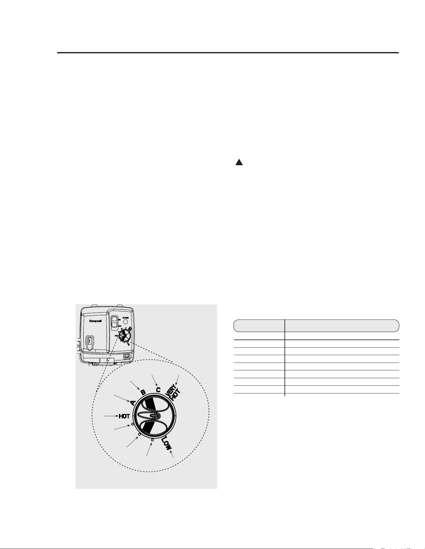
30
Operating the water heater cont.
The.following.is.additional.information.which.aid.in.deter-
mining.a.safe.working.temperature.to.meet.each.household.
need
Maximum.water.temperatures.occur.just.after.the.burner.
has.shut.off..To.determine.the.water.temperature,.turn.on.
a.hot.water.faucet.and.place.a.thermometer.in.the.water.
stream..If.an.adjustment.to.the.water.temperature.is.pre-
ferred,.then.refer.to.the.Water.Heater.User.Display.–.Opera-
tion.Instructions.for.instruction.on.adjusting.the.local.and.
remote.user.display.temperature.setpoints
.
A.condition.known.as.“stacking”.or.“layering”.can.occur.
when.a.series.of.short.and.frequent.hot.water.draws.are.
taken..The.hottest.temperature.water.will.be.at.the.top.of.
the.tank,.closest.to.the.outlet.pipe.delivering.hot.water.to.
the.home
Stacking.can.cause.this.top.layer.of.water.to.be.hatter.than.
the.water.toward.the.bottom.of.the.tank.near.the.gas.control.
(thermostat)...Therefore,.always.remember.to.test.the.water.
temperature.with.your.hand.before.use.and.remember.that.
hotter.water.increases.the.risk.of.scald.injury.
Also,.always.supervise.young.children.or.others.who.are.
incapacitated
The.gas.control.(thermostat).is.constructed.with.a.built.in.
safety.shut-off.device.designed.to.shut.off.the.gas.supply.to.
the.burner.if.the.main.burner.is.extinguished.for.any.reason
The.gas.control.(thermostat).is.also.equipped.with.a.gas.
shut.off.device.that.will.shut.off.the.gas.supply.to.the.burn-
er.if.the.water.heater.exceeds.normal.operating.tempera-
tures..Refer.to.the.“Before.You.Call.For.Service”.section.of.
this.manual,.or.contact.your.dealer
!
WARNING: Should overheating occur or
the gas supply fail to shut off, turn off the
manual gas control valve to the appliance.
If.the.water.heater.has.been.subjected.to.re,.ood.or.physi-
cal.damage,.turn.off.the.manual.gas.control.(shut-off).valve.
and.do.not.operate.the.water.heater.again.until.it.has.been.
checked.by.a.qualied.service.technician
NOTICE:..Replace.any.part.of.the.gas.control.system.
which.has.been.under.water
Time/Temperature Relationship in Scalds
...Water.Temperature. Time.To.Produce.a.Serious.Burn
. 120°F More than 5 minutes
125°F 1
1
/2 to 2 minutes
130°F About 30 seconds
135°F About 10 seconds
140°F Less than 5 seconds
145°F Less than 3 seconds
150°F About 1
1
/2 seconds
155°F About 1 second
Table.courtesy.of.Shriners.Burn.Institute
90° F
113°F
98°F
105°F
120°F
130°F
140°F
150°F
160°F
Temperatures are approximate
Water Temperature Setting…

31
Sequence of Operation…
1. During.initial.start-up.or.a.call.for.heat,.the.control.
will.verify.the.vacuum.switch.is.open
2. Once.the.control.verifies.the.blower.vacuum.switch.is.
open,.the.control.will.energize.the.blower.motor.for.
the.pre-purge.sequence.(approximately.5.seconds)
3. The.control.will.verify.the.blower.vacuum.switch.
has.closed,.ensuring.that.the.blower.is.functioning.
properly.and.that.the.venting.system.is.not.blocked
4. The.control.will.then.proceed.through.a.sequence.of.
self-diagnostics.before.initiating.a.trial.for.ignition
5. During.the.trial.for.ignition,.the.pilot.will.spark.in.
an.attempt.to.light.the.pilot..Once.the.pilot.flame.is.
established,.the.main.gas.valve.will.open.allowing.gas.
to.flow.to.the.main.burner
6. The.main.burner.and.pilot.will.remain.lit.throughout.
the.heat.cycle.until.the.water.temperature.setting.is.
reached
7. Once.the.water.temperature.setting.is.reached,.the.
control.will.close.the.main.gas.valve.and.pilot.valve.
which.will.extinguish.both.the.main.burner.and.pilot.
burner.flames
8. The.blower.motor.will.stay.energized.for.an.additional.
30.seconds.after.the.control.verifies.that.the.burner.
flame.is.extinguished.in.order.to.clear.combustion.
gases.from.the.water.heater..
9. After.the.post-purge.sequence,.the.control.will.
de-energize.the.blower.motor.and.go.into.a.stand-by.
mode.awaiting.the.next.call.for.heat
This.water.heater.is.equipped.with.a.flammable.vapor.
sensor.that.is.monitored.continuously.by.the.electronic.
control.in.all.modes.of.operation.
In.the.event.that.flammable.vapors.are.detected,.the.
control.will.automatically.shut.down.the.water.heater.and.
prevent.the.water.heater.from.being.started.again
The.following.is.a.list.of.materials.that.will.cause.the.
Flammable.Vapor.Sensor.to.shut.down.the.water.heater
.Vapors.of.Gasoline
..Vapors.of.certain.flammable.paints,.stains,.and.thinners
..Vapors.of.vent.pipe.Cement.&.Solvents
..Bleach.(direct.contact.with.flammable.vapor.sensor)
..Some.other.flammable.materials.and.their.vapors
If.the.flammable.vapor.sensor.shuts.down.the.water.heater,.
then.the.electronic.control.will.display.the.appropriate.
error.code.and.you.should.then.promptly.contact.a.
qualified.service.technician
Refer.to.the.“WARNING”.on.page.3.for.additional.
information.
.
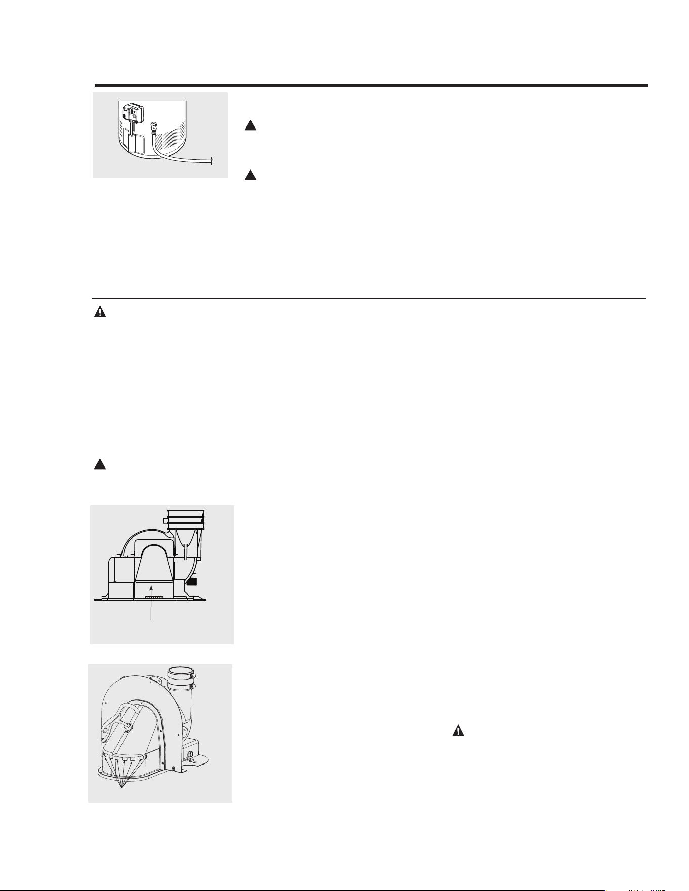
32
Care and cleaning of the water heater.
Draining the Water Heater
!
CAUTION: Shut off gas to the water
heater at the
gas control (thermostat) gas
cock or manual shut-off valve before
draining water.
!
DANGER: Before manually operating the
temperature and pressure relief valve, make
certain no one will be exposed to the hot
water released by the valve. The water
drained from the tank may be hot enough to
present a scald hazard and should be
directed to a suitable drain to prevent injury
or damage.
Before.turning.off.the.cold.water.supply.to.
the.water.heater,.open.a.hot.water.faucet.
allowing.sufficient.cold.water.into.the.
tank.to.prevent.the.risk.of.a.scald.injury.
while.draining.the.water.heater..Once.the.
water.in.the.tank.is.no.longer.hot,.turn.off.
the.cold.water.supply.to.the.water.heater..
Open.a.hot.water.faucet.or.lift.the.handle.
on.the.relief.valve.to.admit.air.to.the.tank.
Attach.a.garden.hose.to.the.drain..
valve.on.the.water.heater.and.direct..
the.stream.of.water.to.a.drain.Open..
the.valve
Routine Preventative Maintenance
Properly.maintained,.your.water.heater.
will.provide.years.of.dependable.trouble-
free.service.
It.is.recommended.that.a.periodic.
inspection.of.the.gas.control.(thermostat),.
burner,.relief.valve,.internal.flue-way.and.
venting.system.should.be.made.by.service.
personnel.qualified.in.gas.appliance.repair
It.is.suggested.that.a.routine.preventative.
maintenance.program.be.established.and.
followed.by.the.user
Inspect.plastic.vent.pipe..Make.certain.
that.all.joints.are.secure.and.that.vent.
pipe.supports.are.all.in.place..Check.
the.outdoor.vent.terminal.to.see.that.it.is.
free.of.obstructions,.and.that.there.is.no.
damage.nearby.casused.by.condensate
Inspect.dilution.air.inlet.and.combustion.
air.inlet.openings..Make.certain.no.
blockage.exists..Clean.any.lint,.dirt.or.oil.
accumulation.that.may.exist
At.least.once.a.year,.lift.and.release.the.
lever.handle.on.the.temperature.pressure.
relief.valve,.located.near.the.top.of.the.
water.heater,.to.make.certain.the.valve.
operates.freely.Allow.several.gallons.to.
flush.through.the.discharge.line.to.an.open.
drain
NOTICE:.If.the.temperature.and.pressure.
relief.valve.on.the.water.heater.discharges.
periodically,.this.may.be.due.to.thermal.
expansion.in.a.closed.water.system.
Contact.the.water.supplier.or.your.
plumbing.contractor.on.how.to.correct.this
DO NOT.plug.the.relief.valve.outlet
A.water.heater’s.tank.can.act.as.a.settling.
basin.for.solids.suspended.in.the.water.
It.is.therefore.not.uncommon.for.hard.
water.deposits.to.accumulate.in.the.bottom.
of.the.tank..If.allowed.to.accumulate,.
these.solids.can.cover.the.gas.control.
(thermostat).sensors,.causing.the.sensors.to.
operate.erratically..Because.accumulated.
solids.can.prevent.the.gas.control.
(thermostat).sensors.from.accurately.
reading.the.water.temperature,.the.water..
at.the.fixture.can.be.hotter.than.the.gas.
control.(thermostat).setting..It.is.suggested.
that.a.few.quarts.of.water.be.drained.from.
the.water.heater’s.tank.every.month.to.
clean.the.tank.of.these.deposits.
Rapid.closing.of.faucets.or.solenoid.valves.
in.automatic.water.using.appliances.can.
cause.a.banging.noise.heard.in.a.water.
pipe.Strategically.located.risers.in.the.
water.pipe.system.or.water.hammer.
arresting.devices.can.be.used.to.minimize.
the.problem
The.anode.rod.should.be.removed.from.the.
water.heater’s.tank.annually.for.inspection.
and.replaced.when.more.than.6”.of.core.
wire.is.exposed.at.either.end.of.the.rod
Make.sure.the.cold.water.supply.is.turned.
off.before.removing.anode.rod
This.water.heater.incorporates.a.
combustion.shut.off.device.that.shuts.
the.operation.of.the.water.heater.down.if.
undesirable.combustion.conditions.occur,.
such.as.the.presence.of.flammable.vapors.
or.blockage.of.the.combustion.air.inlet.
openings..Please.contact.a.qualified.
Service.Technician.if.this.occurs
DANGER: Failure to perform the
recommended Routine Preventative
Maintenance can harm the proper
operation of this water heater, which
can cause carbon monoxide dangers,
excessive hot water temperatures and
other potentially hazardous conditions.
DANGER: Before
manually operating the
relief valve, make certain
no one will be exposed to
the danger of the hot water
released by the valve. The
water may be hot enough to
create a scald hazard. The
water should be released
into a suitable drain to
prevent injury or property
damage.
!
DANGER: Hotter water
increases the potential for
Hot Water Scalds.
Dilution Air Inlet
Tall Models
Blower Assembly Dilution Air Holes
Short.Models.
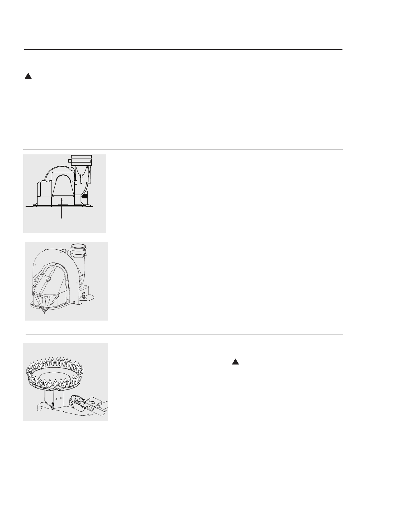
33
Housekeeping
Visually.inspect.the.pilot
To.ensure.sufficient.ventilation.and.
combustion.air.supply,.proper.clearances.
must.be.maintained.
When.installed.in.a.closet,.DO.NOT.block.
or.obstruct.any.of.the.combustion.air.inlet.
openings.located.around.the.perimeter.of.the.
water.heater...A.minimum.of.1”.is.required.
between.these.combustion.air.inlet.openings.
and.any.obstruction
DO.NOT.obstruct.or.block.the.Flammable.
Vapor.Sensor..The.sensor.does.not.
require.any.maintenance.or.cleaning..DO.
NOT.expose.to.cleaning.agents
!
DANGER: Combustible
materials, such as clothing,
cleaning materials, or
flammable liquids, etc., must
not be placed against or next
to the water heater.
Burner Inspection
Visually.inspect.the.pilot.flame.and.main.
burner.annually
Through.the.sight.glass,.inspect.the.pilot.
and.burner.lighting..If.any.unusual.pilot.
or.burner.operation.is.noted,.the.water.
heater.should.be.shut.off.until.qualified.
service.assistance.can.be.obtained
!
CAUTION: For your safety, cleaning of
the burner must be performed only by
qualified service personnel, as it involves the
disconnection of gas piping and leak testing.
The burner chamber is a sealed area. If the
burner access door is removed, the burner
access door gasket must be replaced.
For.cleaning,.remove.the.burner.from.the.
water.heater.A.vacuum.cleaner.can.be.
used.on.the.burner.and.floor.shield.inside.
the.water.heater..The.burner.can.also.be.
cleaned.by.scrubbing.with.mild.detergent
Proper.burner.flame.pattern
Venting System Inspection
The.water.heater’s.internal.flue.must.be.
inspected.annually.to.be.certain.it.is.clean.
by.removing.the.blower.assembly.and.flue.
baffle
When.reinstalling.the.flue.baffle.make.
certain.it.is.hung.securely.by.its.hanger.at.
the.top.of.the.flue.way
Reinstall.the.blower.assembly
Inspect.plastic.vent.pipe..Make.certain.
that.all.joints.are.secure.and.that.vent.
pipe.supports.are.all.in.place..Check.
the.outdoor.vent.terminal.to.see.that.it.is.
free.of.obstructions,.and.that.there.is.no.
damage.nearby.caused.by.condensate
Inspect.dilution.air.holes..Make.certain.no.
blockage.exists..Clean.any.lint,.dirt.or.oil.
accumulation.that.may.exist
Test.for.spillage.at.the.dilution.air.holes.
after.5.minutes.of.burner.operation..Place.
a.blown.out.match.or.candle.close.to.the.
dilution.are.holes..The.smoke.from.the.
candle.or.match.should.be.drawn.into.the.
dilution.air.holes..If.the.smoke.is.pushed.
away.from.the.dilution.air.holes,.the.
blower.or.vent.system.may.be.blocked..
Contact.qualified.service.personnel
Dilution Air Inlet
Tall Models
Blower Assembly Dilution Air Holes
Short.Models.

34
Vacation and Extended Shut-Down
If.the.water.heater.is.to.remain.idle.for.an.
extended.period.of.time,.the.power.and.
water.to.the.appliance.should.be.turned.off.
to.conserve.energy.and.prevent.a.build-up.
of.dangerous.hydrogen.gas
The.water.heater.and.piping.should.be.
drained.if.they.might.be.subjected.to.
freezing.temperatures
After.a.long.shut-down.period,.the.
water.heater’s.operation.and.controls.
should.be.checked.by.qualified.service.
personnel..Make.certain.the.water.heater.
is.completely.filled.again.before.placing.it..
in.operation
NOTICE: Refer to the
Hydrogen Gas Caution in the
Operating Instructions.
Anode Rod
This.water.heater.is.equipped.with.an.
anode.rod.designed.to.prolong.the.life.
of.the.glass.lined.tank.The.anode.rod.is.
slowly.consumed,.thereby.eliminating.or.
minimizing.corrosion.of.the.glass.lined.
tank.
Water.sometimes.contains.a.high.sulfate.
and/or.mineral.content.and.together.with.
cathodic.protection.process.can.produce.
a.hydrogen.sulfide,.or.rotten.egg.odor.in.
the.heated.water.Chlorination.of.the.water.
supply.should.minimize.the.problem
NOTICE: Do not remove
the anode rod from the water
heater’s tank, except for
inspection and/or replacement,
as operation with the anode
rod removed will greatly
shorten the life of the glass
lined tank and will exclude
warranty coverage.
Care and cleaning of the water heater
35
Before You Call For Service…
Troubleshooting Tips
Save time and money! Review the charts on the following pages first and you may not need to call for service.
This.water.heater.incorporates.a.combustion.shut.off.device.that.shuts.the.operation.of.the.water.heater.
down.if.undesirable.combustion.conditions.occur,.such.as.the.presence.of.flammable.vapors.or.blockage.of.
the.combustion.air.inlet.openings..Please.contact.a.qualified.Service.Technician.if.this.occurs
CAUTION: For your safety DO NOT attempt repair of gas piping, gas control (thermostat), burners, vent connectors or other
safety devices. Refer repairs to qualified service personnel.
Problem. Possible Causes. . What To Do
Condensation This.usually.happens.when... .This.is.normal.After.the.water.in.the.tank.warms.
. a.new.water.heater.is.. . up,.the.condensation.will.disappear.If,.however,.the..
. filled.for.the.first.time.. . condition.persists,.examine.the.piping.and.fittings..
. . . for.possible.leaks
Moisture.from.the.products. . This.is.normal.and.will.disappear.in.time.Excessive.
. of.combustion.condensing.. . condensation.can.cause.main.burner.outage.
. on.the.tank.surface
An.undersized.water.. . Use.a.water.heater.size.that.meets.the.requirements.
. heater.will.cause.. . of.your.needs.
. condensation.
Yellow flame. Scale.on.top.of.the.burner. . Contact.a.qualified.service.technician.to.remove.scale
or soot
Flue.or.Combustion.air.inlet.. . Remove.obstruction.or.debris.from.flue.or
. openings.are.restricted.. . combustion.air.inlet.openings.on.water.heater.jacket.
. Not.enough.combustion.or. .Proper.operation.of.the.water.heater.requires.air.for.
. ventilation.air.supplied.to. . combustion.and.ventilation.See.the.Combustion.and.
. the.water.heater.location. . Ventilation.Air.information.in.the.“Installing.The.. .
. . . Water.Heater”.section.of.this.manual
Unable to light Air.in.gas.line. . Contact.a.qualified.service.technician.to.purge.the.air..
the main burner from.the.gas.line
. Blocked.Exhaust. Contact.a.qualified.service.technician.to.evaluate.vent..
. . . .pipe.for.blockage
Pressure.Switch. . Make.sure.the.pressure.switch.hose.is.not."kinked"
Wire.Connection.not.fully. . Contact.a.qualified.service.technician.to.confirm.wire..
. secured. . connections
Combustion.Shut-off.Device . Combustion.shut-off.device.should.be.inspected.by.a..
. tripped,. . qualified.service.technician
. Gas.Control.Problem. . Contact.a.qualified.service.technician
Main burner does not.. Combustion.Shutoff.Device. . The.combustion.shutoff.device.should.be.inspected
stay lit. Tripped. . by.a.qualified.service.technician
36
Problem. Possible Causes. . What To Do
Rumbling noise Scale.and.sediment. . Drain.the.water.heater.to.remove.scale.and.sediment.from..
. . the.tank..Refer.to.the.top.of.page.31.
Relief valve. Pressure.build.up.. . This.is.an.unacceptable.condition.and.must.be
producing popping. caused.by.thermal.. . corrected.Contact.the.water.supplier.or.plumbing.
noise or draining. expansion.to.a.. . contractor.on.how.to.correct.this.Do.not.plug.the
closed.system. . relief.valve.outlet.
Not enough or. Water.usage.may.have... . Wait.for.the.water.heater.to.recover.after.an
no hot water exceeded.the.capacity. . abnormal.demand
of.the.water.heater
Low.gas.pressure. . Check.gas.supply.pressure.and.manifold.pressure
. The.gas.control.(thermostat).. . See.the.“Water.Temperature.Setting”.of.The.Water...
. may.be.set.too.low. . Heater.section.of.this.manual
. Leaking.or.open.hot.. . Make.sure.all.faucets.are.closed
. water.faucets
. Check.valve.error.codes. . Refer.to.gas.valve.error.code.table.on.page.37
. “ON/OFF”.switch.turned.off. . Turn.“ON”
. Blower.unplugged. . Plug.in.Verify.power.supply.(120VAC)
. Combustion.Shutoff.System.. . .Contact.a.qualified.service.technician
. tripped.. .
Water is too hot The.gas.control.(thermostat).. ●.See.the.“Water.Temperature.Setting”.of.The.Water...
. is.set.too.high. . Heater.section.of.this.manual
Gas.Control.(Thermostat). ●.Contact.a.qualified.service.technician.to.replace.the..
. Defective. . gas.control.(thermostat)
Before You Call For Service…
Troubleshooting Tips
Save time and money! Review the charts on the following pages first and you may not need to call for service.
This.water.heater.incorporates.a.combustion.shut.off.device.that.shuts.the.operation.of.the.water.heater.down.
if.undesirable.combustion.conditions.occur,.such.as.the.presence.of.flammable.vapors.or.blockage.of.the.
combustion.air.inlet.openings..Please.contact.a.qualified.Service.Technician.if.this.occurs
CAUTION: For your safety DO NOT attempt repair of gas piping, gas control (thermostat), burners, vent connectors or
other safety devices. Refer repairs to qualified service personnel.
CAUTION: Make certain power to water heater is “OFF” before removing protective cover FOR ANY REASON.
CAUTION: Label all wires prior to disconnection when servicing controls. Wiring errors can cause improper and
dangerous operation. VERIFY PROPER OPERATION AFTER SERVICING.
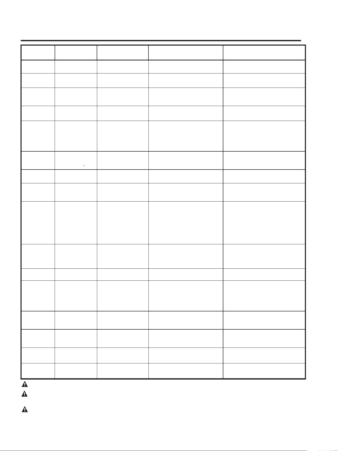
37
Gas Valve LED Codes
CAUTION: Make certain power to water heater is “OFF” before removing protective cover FOR ANY REASON.
CAUTION: Label all wires prior to disconnection when servicing controls. Wiring errors can cause improper and
dangerous operation. VERIFY PROPER OPERATION AFTER SERVICING.
CAUTION: For your safety DO NOT attempt repair of gas piping, remote control, burners, vent connectors or other
safety devices. Refer repairs to qualified service personnel.
LCD CODE
For Optional
Display
GAS VALVE
LED
STATUS/PROBLEM PROBABLE CAUSE SOLUTION
None
Short.ash.once.
every.four.seconds
IDLE.(no.call.for.heat,.
no.fault.conditions)
Temperature.setpoint.achieved.and.
burner.is.off
No.solution.required
None
“Heartbeat”,.alter-
nates.bright/dim
Call.For.Heat.(no.fault.
conditions).
Water.temperature.is.below.set-
point.and.burner.is.on
No.solution.required
12
One.Flash,.three.
second.pause..
Low.ame.signal.
(control.continues.to.
operate).
Pilot.tube.restriction,.carbon.build-
up.on.electrode,.pilot.wire.damage.
or.gas.supply
1.Gas.supply.pressure.is.low
2.Low.voltage.supply
3.Pilot.replacement
44
Two.Flash,.three.
second.pause
Pressure.switch.failed.
closed
Pressure.switch.tube.blockage.or.
faulty.pressure.switch
1..Pressure.switch.wiring.incorrect
2.Replace.pressure.switch
46
Three.Flash,.three.
second.pause
Pressure.switch.failed.
open.
Vent.blockage.or.improper.insalla-
tion,.switch.tube.blockage,.faulty.
switch,.blower.improper.operation.
or.temperature.switch.open.
1..Pressure.switch.wiring.incorrect
2.Replace.pressure.switch
3..Air.intake.or.exhaust.obstructed
4..Replace.blower.temperature.switch
5.Replace.blower
31
Four.Flash,.three.
second.pause.
TCO.limit.lockout
Thermal.well.fault,.gas.control.
fault.or.tank.is.not.lled.with.
water.
1..Reset.valve.and.check.for.proper.
valve.cycling
2..Make.sure.tank.is.full.of.water
14
Five.Flash,.three.
second.pause.
Flame.out.of.sequence
Pilot.or.burner.valve.has.failed.
open.
1.Replace.gas.valve.control
11
Six-One.Flash,.
three.second.pause.
Failed.trial.for.ignition
Insufcient.gas.supply,.unstable.
pilot,.carbon.buildup.on.electrode.
or.wire/pilot.tube.damage
1.Check.gas.supply
2.Replace.pilot
45
Six-Two.Flash,.
three.second.pause
Recycle.limit.-.PS/limit.
opened
Vent.blockage.or.improper.instal-
lation,.switch.tube.blockage,.faulty.
switch,.blower.improper.operation,.
blower.temperature.switch.open.or.
excessive.wind.at.vent.termination
1..Pressure.switch.wiring.incorrect
2.Replace.pressure.switch
3..Air.intake.or.exhaust.obstructed
4..Replace.blower.temperature.switch
5.Replace.blower
6..Check.for.vent.termination.compli-
ance.as.stated.in.this.manual
13
Six-Three.Flash,.
three.second.pause
Recycle.limit.-.ame.
lost
Pilot.tube.restriction,.low.gas.sup-
ply.pressure,.carbon.buildup.on.
electrode,.wire/pilot.tube.damage.
or.combustion.air.port.blockage
1.Gas.supply.pressure.is.low
2.Jacket.air.holes.obstructed
3.Pilot.replacement
14
Six-Four.Flash,.
three.second.pause
Soft.Lockout.-.ame.
out.of.sequence.sensed
Valve.stuck.in.open.position 1.Replace.gas.valve.control
47
Seven.Flash,.three.
second.pause.
Flammable.vapor.sen-
sor.lockout.
Gasoline.or.other.ammable.gas.
was.detected.near.the.appliance.or.
the.sensor.has.failed
1..Verify.no.gasoline.or.ammable.
vapors.are.present
2..Reset.control.using.ON/OFF.switch.
on.the.gas.control.valve
3.Replace.the.ammable.vapor.sensor
49
Eight-One.Flash,.
three.second.pause
FVS.fault.detected
Flammable.vapor.sensor.resistance.
is.out.of.range,.wiring.to.FV.sen-
sor.is.faulty.or.control.is.faulty
1.Replace.FV.sensor
2.Replace.FV.sensor.wiring
3.Replace.gas.control.valve
89
Eight-Two.Flash,.
three.second.pause
Temperature.sensor.
fault.detected
Thermal.well.fault
1..Check.thermal.well.wiring.connec-
tion
2..Replace.thermal.well
15
Eight-Three.Flash,.
three.second.pause.
Electronics.fault.de-
tected
Thermal.well.fault.or.gas.control.
fault
1.Replace.gas.control.valve
2.Replace.thermal.well
93
Eight-Four.Flash,.
three.second.pause
Valve.fault.detected
Gas.control.valve.needs.to.be.reset.
or.has.been.damaged
1..Cycle.power.to.gas.control.valve
2.Replace.gas.control.valve
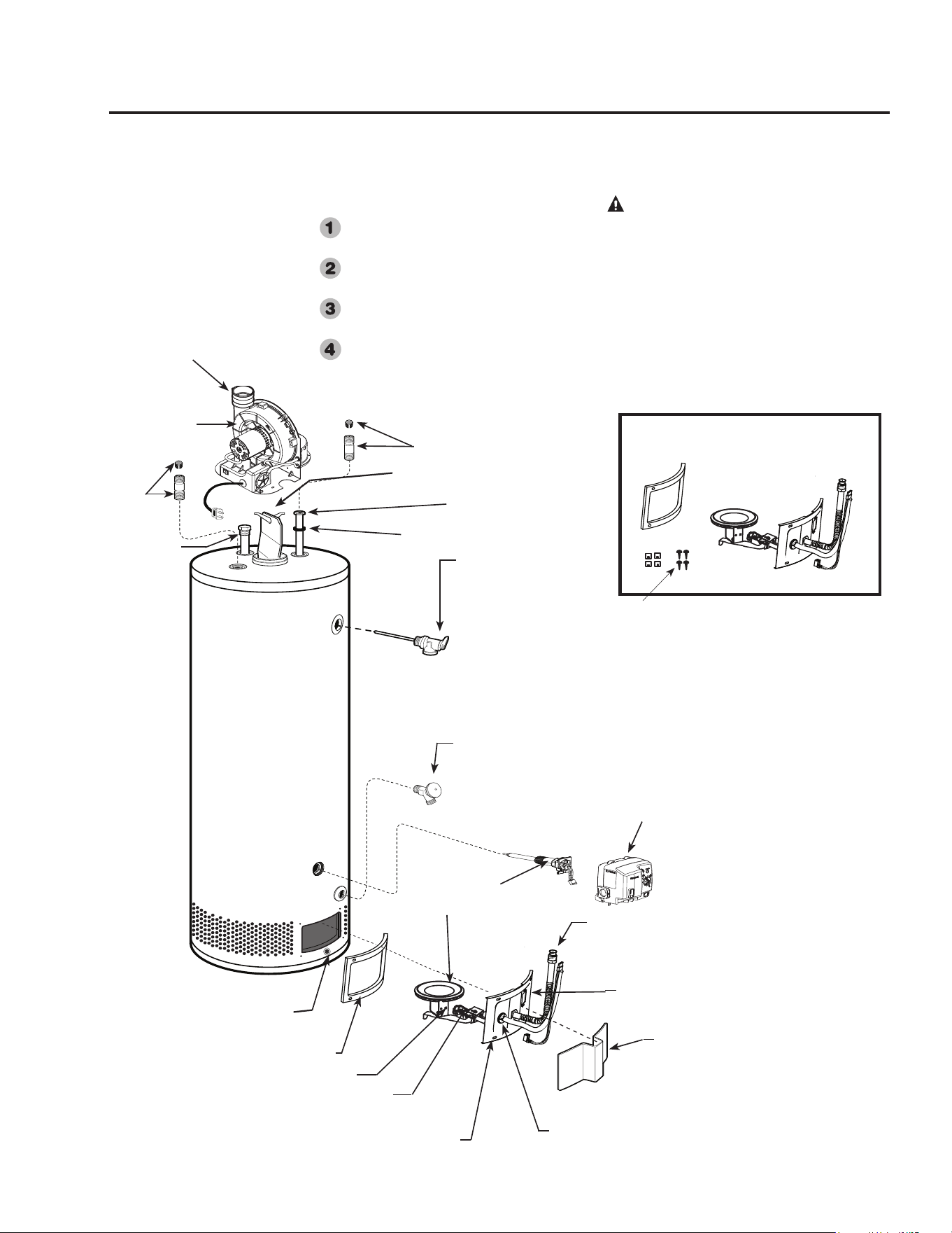
38
Replacement Parts.
For.40.and.50.gallon.models.using.natural.or.LP.gas
Instructions For Placing a Parts Order
All.parts.orders.should.include:
...The.model.and.serial.number.of.the.
water.heater.from.the.rating.plate
...Specify.type.of.gas.(natural.or.LP)
as.marked.on.the.rating.plate.
...Part.description.(as.noted.below).and.
number.of.parts.desired
..Refer.to.page.40
CAUTION: For your safety, DO
NOT attempt repair of gas piping,
gas control (thermostat), burners,
vent connectors or other safety devices.
Refer repairs to qualified service
personnel.
Use only original equipment
replacement parts.
Blower.
Assembly
Flue.baffle.and.hanger
Anode.rod
**.Heat.Trap.Nipple
**.Heat.
Trap.
Nipple
Dip.tube
Dip.tube.gasket
Drain.valve
Temperature.and.pressure.
relief.valve
Gas.Control.(Thermostat)
*Igniter
*Burner.supply.tube
*Burner
Jacket.Door
.*Burner.Access.Door.Grommet
.*Sight.Glass
.*Burner.Access.Door
*Burner.Access.Door.Gasket
*Burner..orifice
*Burner.Assembly.Kit
The.kit.provides.extra.speed.clips.
and.tamper.resistant.screws
**.May.differ.in.actual.appearance
Flammable.Vapor.Sensor
Rubber.
Coupling
Gas.Control.Shank

39
Notes:
This.page.intentionally.left.blank
40
1. Should.you.have.any.questions.about.your.new.water.heater,.or.if.it.requires.adjustment,.repair,.or.routine.
maintenance,.it.is.suggested.that.you.first.contact.your.installer,.plumbing.contractor.or.previously.agreed.upon.service.
agency.In.the.event.the.firm.has.moved,.or.is.unavailable,.refer.to.the.telephone.directory,.commercial.listings.or.local.
utility.for.qualified.service.assistance
2. Should.your.problem.not.be.solved.to.your.complete.satisfaction,.you.should.then.contact.the.Manufacturer’s.National.
Service.Department.at.the.following.address:.
. .. . . 1241.Carwood.Court
. .. . . Montgomery,.Alabama.36117
. .. . . Phone:.1-800-432-8373.
. When.contacting.the.manufacturer,.the.following.information.will.be.requested:
a. Model.and.serial.number.of.the.water.heater.as.shown.on.the.rating.plate.attached.to.the.jacket.of.the.heater
b. Address.where.the.water.heater.is.located.and.physical.location
c. Name.and.address.of.installer.and.any.service.agency.who.performed.service.on.the.water.heater
d. Date.of.original.installation.and.dates.any.service.work.was.performed
e. Details.of.the.problems.as.you.can.best.describe.them
f. List.of.people,.with.dates,.who.have.been.contacted.regarding.your.problem
The.Commonwealth.of.Massachusetts.requires.compliance.with.regula-
tion.
508:.Modications.to.NFPA-54,.Chapter.10.:.248.CMR.400.
and.500.for.installation.of.through.–.the.–.wall.vented.gas.appliances.as.
follows:
(1).Revise.NFPA-54.section.10542.by.adding.a.second.exception.as.fol-
lows:
Existing.chimneys.shall.be.permitted.to.have.their.use.continued.when.a.gas.
conversion.burner.is.installed,.and.shall.be.equipped.with.a.manually.reset.
device.that.will.automatically.shut.off.the.gas.to.the.burner.in.the.event.of.a.
sustained.back-draft
(2).Revise.1083.by.adding.the.following.additional.requirements:
(a).For.all.side.wall.horizontally.vented.gas.fueled.equipment.installed.in.
every.dwelling,.building.or.structure.used.in.whole.or.in.part.for.residential.
purposes,.including.those.owned.or.operated.by.the.Commonwealth.and.
where.the.side.wall.exhaust.vent.termination.is.less.than.seven.(7).feet.above.
nished.grade.in.the.area.of.the.venting,.including.but.not.limited.to.decks.
and.porches,.the.following.requirements.shall.be.satised:.
1.INSTALLATION.OF.CARBON.MONOXIDE.DETECTORS.At.the.time.
of.installation.of.the.side.wall.horizontal.vented.gas.fueled.equipment,.the.
installing.plumber.or.gastter.shall.observe.that.a.hard.wired.carbon.monox-
ide.detector.with.an.alarm.and.battery.back-up.is.installed.on.the.oor.level.
where.the.gas.equipment.is.to.be.installed.In.addition,.the.installing.plumber.
or.gastter.shall.observe.that.a.battery.operated.or.hard.wired.carbon.mon-
oxide.detector.with.an.alarm.is.installed.on.each.additional.level.of.the.dwell-
ing,.building.or.structure.served.by.the.side.wall.horizontal.vented.gas.fueled.
equipment.It.shall.be.the.responsibility.of.the.property.owner.to.secure.the.
services.of.qualied.licensed.professionals.for.the.installation.of.hard.wired.
carbon.monoxide.detectors
a.In.the.event.that.the.side.wall.horizontally.vented.gas.fueled.equipment.is.
installed.in.a.crawl.space.or.an.attic,.the.hard.wired.carbon.monoxide.detec-
tor.with.alarm.and.battery.back-up.may.be.installed.on.the.next.adjacent.oor.
level
b.In.the.event.that.the.requirements.of.this.subdivision.can.not.be.met.at.the.
time.of.completion.of.installation,.the.owner.shall.have.a.period.of.thirty.(30).
days.to.comply.with.the.above.requirements;.provided,.however,.that.during.
said.thirty.(30).day.period,.a.battery.operated.carbon.monoxide.detector.with.
an.alarm.shall.be.installed
2.APPROVED.CARBON.MONOXIDE.DETECTORS.Each.carbon.
monoxide.detector.as.required.in.accordance.with.the.above.provisions.shall.
comply.with.NFPA.720.and.be.ANSI/UL.2034.listed.and.IAS.certied.
3.SIGNAGE.A.metal.or.plastic.identication.plate.shall.be.permanently.
mounted.to.the.exterior.of.the.building.at.a.minimum.height.of.eight.(8).feet.
above.grade.directly.in.line.with.the.exhaust.vent.terminal.for.the.horizon-
tally.vented.gas.fueled.heating.appliance.or.equipment.The.sign.shall.read,.
in.print.size.no.less.than.one-half.(1/2).inch.in.size,."GAS.VENT.DIRECTLY.
BELOW.KEEP.CLEAR.OF.ALL.OBSTRUCTIONS"
4.INSPECTION.The.state.or.local.gas.inspector.of.the.side.wall.horizon-
tally.vented.gas.fueled.equipment.shall.not.approve.the.installation.unless,.
upon.inspection,.the.inspector.observes.carbon.monoxide.detectors.and.
signage.installed.in.accordance.with.the.provisions.of.248.CMR.508(2)(a)1.
through.4.
(b).EXEMPTIONS:.The.following.equipment.is.exempt.from.248.CMR.
508(2)(a)1.through.4:.
1.The.equipment.listed.in.Chapter.10.entitled."Equipment.Not.Required.To.
Be.Vented".in.the.most.current.edition.of.NFPA.54.as.adopted.by.the.Board;.
and.
2.Product.Approved.side.wall.horizontally.vented.gas.fueled.equipment.in-
stalled.in.a.room.or.structure.separate.from.the.dwelling,.building.or.structure.
used.in.whole.or.in.part.for.residential.purposes.
(c).MANUFACTURER.REqUIREMENTS.-.GAS.EqUIPMENT.VENTING.
SYSTEM.PROVIDED.When.the.manufacturer.of.Product.Approved.side.
wall.horizontally.vented.gas.equipment.provides.a.venting.system.design.or.
venting.system.components.with.the.equipment,.the.instructions.provided.
by.the.manufacturer.for.installation.of.the.equipment.and.the.venting.system.
shall.include:
1.Detailed.instructions.for.the.installation.of.the.venting.system.design.or.
the.venting.system.components;.and
2.A.complete.parts.list.for.the.venting.system.design.or.venting.system.
(d).MANUFACTURER.REqUIREMENTS.-.GAS.EqUIPMENT.VENTING.
SYSTEM.NOT.PROVIDED.When.the.manufacturer.of.a.Product.Approved.
side.wall.horizontally.vented.gas.fueled.equipment.does.not.provide.the.parts.
for.venting.the.ue.gases,.but.identies."special.venting.systems",.the.fol-
lowing.requirements.shall.be.satised.by.the.manufacturer:
1.The.referenced."special.venting.system".instructions.shall.be.included.with.
the.appliance.or.equipment.installation.instructions;.and.
2.The."special.venting.systems".shall.be.Product.Approved.by.the.Board,.
and.the.instructions.for.that.system.shall.include.a.parts.list.and.detailed.
installation.instructions.
(e).A.copy.of.all.installation.instructions.for.all.Product.Approved.side.wall.
horizontally.vented.gas.fueled.equipment,.all.venting.instructions,.all.parts.
lists.for.venting.instructions,.and/or.all.venting.design.instructions.shall.
remain.with.the.appliance.or.equipment.at.the.completion.of.the.installation.
Important.Instructions.for.the.Commonwealth.of.Massachusetts
IF.YOU.NEED.SERVICE