SEALEY, 500A PROFESSIONAL GAS/GASLESS
MIG/MMA/TIG INVERTER WELDER WITH
PORTABLE WIRE FEEDER 415V 3PH
MODEL NO: POWERMIG500i & POWERMIG500Wi
Thank you for purchasing a Sealey product. Manufactured to a high standard, this product will, if used according to these instructions,
and properly maintained, give you years of trouble free performance.
IMPORTANT: PLEASE READ THESE INSTRUCTIONS CAREFULLY. NOTE THE SAFE OPERATIONAL REQUIREMENTS, WARNINGS & CAUTIONS. USE
THE PRODUCT CORRECTLY AND WITH CARE FOR THE PURPOSE FOR WHICH IT IS INTENDED. FAILURE TO DO SO MAY CAUSE DAMAGE AND/OR
PERSONAL INJURY AND WILL INVALIDATE THE WARRANTY. KEEP THESE INSTRUCTIONS SAFE FOR FUTURE USE.
1. SAFETY
1.1. WARNING! It is the user’s responsibility to check the following:
9 Check all electrical equipment and appliances to ensure that they are safe before using.
9 Inspect power supply leads, plugs and all electrical connections for wear and damage.
9 Ensure that the insulation on all cables and on the appliance is safe before connecting it to the power supply.
8 DO NOT use worn or damaged cables, plugs or connectors.
9 EnsurethatanyfaultyitemisrepairedorreplacedimmediatelybyaSealeyqualiedtechnician.
9 Ifthecableorplugisdamagedduringuse,switchotheelectricitysupplyandremovefromuse.
9 SealeyrecommendthatanRCD(ResidualCurrentDevice)isusedwithallelectricalproducts.
Important:Ensurethatthevoltageratingontheappliancesuitsthepowersupplytobeusedandthattheplugisttedwiththe
correct fuse.
8 DO NOT pull or carry the appliance by the power cable.
8 DO NOT pull the plug from the socket by the cable.
1.2. GENERAL SAFETY
9 Welding power sources are not suitable for use in rain or snow
9 The output is rated at an ambient temperature of 20°C and the welding time may be reduced at higher temperatures.
9 Risk of electric shock: Electric shock from welding electrode can kill.
8 DO NOT weld in the rain or snow.
8 DO NOToperateonaslopeorunevenground.
9 Weardryinsulatinggloves.
8 DO NOT touch electrode with bare hands.
8 DO NOTwearwetordamagedgloves.
9 Protect yourself from electric shock by insulating yourself from workpiece.
8 DO NOT open the equipment enclosure.
WARNING! Welding fumes: Breathing welding fumes can be hazardous to your health. Keep your head out of the fumes.
9 Use equipment in an open area.
9 Useventilatingfantoremovefumes.
WARNING!Riskinducedbyweldingsparks:Weldingsparkscancauseexplosionorre.Keepammablesawayfromwelding.
8 DO NOTweldnearammables.Weldingsparkscancauseres.Haveareextinguishernearbyandawatchpersonreadytouseit.
8 DO NOT weld on drums or any closed containers.
WARNING! Risk induced by the arc: Arc rays can burn eyes and injure skin.
9 Useweldinghelmetwithcorrectshadeoflter.Wearcompletebodyprotection.
WARNING!Riskinducedbyelectromagneticelds:Weldingcurrentproduceselectromagneticeld.
8 DO NOTusewithmedicalimplants.Nevercoilweldingcablesaroundyourbody.Routetheweldingcablestogether.
9 The operator should be properly trained to use the welder safely and should be informed about the risks relating to MIG and ARC welding
procedures, the associated protection measures and emergency procedures.
9 DANGER!Unplugthewelderfromthemainspowersupplybeforeperformingmaintenanceorservice.
9 Keepthewelderandcablesingoodworkingorderandcondition.(Takeimmediateactiontorepairorreplacedamagedparts).
9 Usegenuinepartsandaccessoriesonly.(Nonrecommendedpartsmaybedangerousandwillinvalidatethewarranty).
9 Use an air hose to regularly blow out any dirt from the liner and keep the welder clean for best and safest performance.
9 Checkandspraythegascupandcontacttipregularlywithanti-spattersprayavailablefromyourSealeystockist.
9 Locatewelderinadequateworkingareaforitsfunction.Ensureareahasadequateventilationasweldingfumesareharmful.
9 Keep working area clean, tidy and free from unrelated materials. Also ensure the working area has adequate lighting, and that a fire
extinguisher is at hand.
WARNING!: Always use a welding helmet or mask to protect your eyes.
POWERMIG500i POWERMIG500Wi Issue:2 12/03/25
Original Language Version
© Jack Sealey Limited
Refer to
instructions
Welding sparks
can cause
explosionsorre.
Arc rays can burn eyes
And injure skin.
Breathing welding fumes
can be hazardous to your
health.
Electrical
shock hazard
Hotsurfaces Do not use in
thevicinityofa
pacemaker
Wear a
welding mask
Wear
protective
gloves
Wear safety
footwear
Wear
protective
clothing
Do not use in
rain

9 UsespecialfireresistantprotectiveclothingandDO NOTallowtheskintobeexposedtotheultravioletandinfraredraysproducedbythe
arc.Otherpeopleinthevicinityofthearcshouldbeprotectedbyshieldsofnonreflectingweldingcurtains.
9 Theoperatorshouldbeadequatelyinsulatedfromtheelectrode,theworkpieceandanyaccessibleearthedmetalpartsinthevicinityby
the wearing of safety shoes and welding gauntlets plus the aforementioned safety clothing.
9 Wherenecessarytheoperatorshouldworkoninsulatingmattsoronaninsulatedsafetyplatforminelevatedpositions.
9 Removeillfittingclothing,removeties,watches,rings,andotherloosejewellery,andcontainlonghair.
9 Ensure the workpiece is correctly secured before operating the welder.
9 Avoidunintentionalcontactwithworkpiece.Accidentaloruncontrolleduseofthetorchmaybedangerousandwillwearthenozzle.
9 Keepnonessentialpersonsawayfromtheworkingarea.Anypersonsworkingwithintheareamustuseprotectiveheadshieldand
gloves.
9 Operatorsmustreceiveadequatetrainingbeforeusingthewelder.Theweldermustonlybeoperatedundersupervision.
9 Stand correctly keeping a good footing and balance, and ensure the floor is not slippery, and wear non-slip shoes.
9 Turnvoltageswitchto“0”oroffwhennotinuse.
8 DO NOT operate the welder if it or its cables are damaged and DO NOT attempt to fit any non genuine torches, components, or parts to
the welder unit.
8 DO NOT get welder wet or use in damp or wet locations or areas where there is condensation.
▲ DANGER! DO NOT weld near inflammable materials, solids, liquids, or gases, and DO NOTweldcontainersorpipeswhichhaveheld
flammablematerialsorgases,liquidsorsolids.Avoidoperatingonmaterialscleanedwithchlorinatedsolventsornearsuchsolvents.
8 DO NOTtouchanylivemetalpartsofthetorchorelectrodewhilethemachineisswitchedon.
8 DO NOT weld on any containers which are under pressure.
8 DO NOT pull the welder by the mains cable or by the umbilical connection cable.
8 DO NOT pull the wire feed unit by the umbilical connection cable or by the torch cable, and DO NOT bend or strain cables, protect from
sharporabrasiveitems,andDO NOT stand on cables or leads. Protect from heat. Lengths of slack must be gathered & neatly coiled.
8 DO NOT place cables where they endanger others.
8 DO NOTtouchthetorchorworkpieceimmediatelyafterweldingastheywillbeveryhot.Allowtocool.
8 DO NOT operate welder while under the influence of drugs, alcohol or intoxicating medication, or if fatigued.
9 When not in use store the welder in a safe, dry, childproof area.
8 DO NOT weld in the rain.
9 Provideadequateventilationorfacilitiesfortheremovalforofweldingfumesfromnearthearc.TheriskshouldbeassessedbyaHealth
and Safety professional in relation to the exposure limits for the welding fumes, which will depend on their composition, concentration and
the exposure time
WARNING! Electromagnetic interference: The electromagnetic fields generated by the welding process may interfere with the operation
ofelectricalandelectronicequipment.Usersofvitalelectronicandelectricaldevicessuchaspacemakersandrespiratorsareadvised
nottoremainintheviscinityofanoperatingweldingmachine.Ifindoubtseekmedicaladvicebeforeenteringaweldingarea.Usersof
suchdevicesshouldnotoperatetheweldingmachine.Thisweldercomplieswiththerequirementsofthetechnicalstandardfortheuse
ofthistypeofproduct,onlyandexclusivelyinindustrialenvironmentsandforprofessionalpurposes.Itisnotguaranteed to meet
electronic compatibility requirements in the home.
WARNING! Gas safety: Storegascylindersinaverticalpositiononlyandensurethestorageareaiscorrectlysecured.
8 DO NOT store gas cylinders in areas where temperature exceeds 50°C. DO NOT use direct heat on a cylinder. Keep gas cylinders cool.
8 DO NOTattempttorepairormodifyanypartofagascylinderorvalve,andDO NOT puncture or damage a cylinder.
8 DO NOTobscureorremoveanyofficiallabelsfromacylinder.Alwayscheckthegasidentitybeforeuse.Avoidgettinggascylindersoily
or greasy.
8 DO NOT trytoliftorhandlecylinderbyitscap,guardorvalve.Alwayskeepcapsandguardsinplaceandclosevalvewhennotinuse.
9 Thegascylinderisheavy,usemechanicalliftingequipment.Ensurethecylinderiscorrectlysituatedonthewelderbasestandand
secured with chain.
9 Riskassessment:Whereweldingisunavoidableinawkwardsituationssuchasinconfinedspaces,inenvironmentswithincreasedrisk
ofelecticshock,andinthepresenceofinflamableorexplosivematerials,ariskassessmentmustbecarriedoutbyanexperiencedand
qualifiedexpertprofessionalinconsultationwithprovidersofemergencyservicestoensurethatoperationsarecarriedoutinthesafest
possible way.
WARNING!Risk induced by electomagnetic fields: Welding current produces a electomagnetic field. DO NOT use with medical implants..
Nevercoilweldingcablesaroundyourbody.Routetheweldingcablestogether.
WARNING! DO NOT placetheweldingpowersourceonatiltedplaneasthismayleadtotheunittopplingover.
8 DO NOT use welding power source for pipe thawing
2. INTRODUCTION
MultiprocessIGBTinverterGas/GaslessMIG/TIG/MMAweldersuitableforprofessionalfabricatorsandworkshops,aswellas
mechanics and technicians. Fitted with a portable wire feeder allowing access into high or tight spaces that otherwise would not be
possible.Maximumoutputof500AmakingitidealforweldingalargevarietyofmetalsincludingSteel,StainlessSteelupto20mm.
2T/4Ttorchtriggerfunctionallowinggreaterprecisionduringlongerwelds.Featuresshortcircuit,over-heatingandover-current
protection. Supplied with 2m power cable, 2m earth clamp, 3m Euro Mig torch and 2m Electrode holder. Wire capacity of 5-15kg with a
diameter of 0.6mm to 1.6mm. Electrode capacity from 1.6mm to 5mm. Duty Cycle: MIG 60% @ 500A, MMA 60% @ 500A, TIG 60% @
500A.POWERMIG500Wiisalsosuppliedwithawatercoolertoprolongdutycycleandeciency
© Jack Sealey Limited
Original Language Version
POWERMIG500i POWERMIG500Wi Issue:2 12/03/25
3. CONTENTS
4. SPECIFICATION
5. op OPERATION
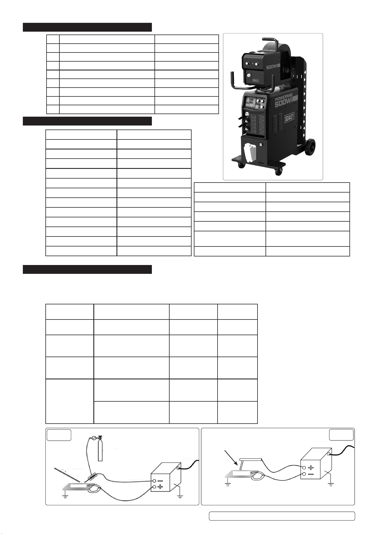
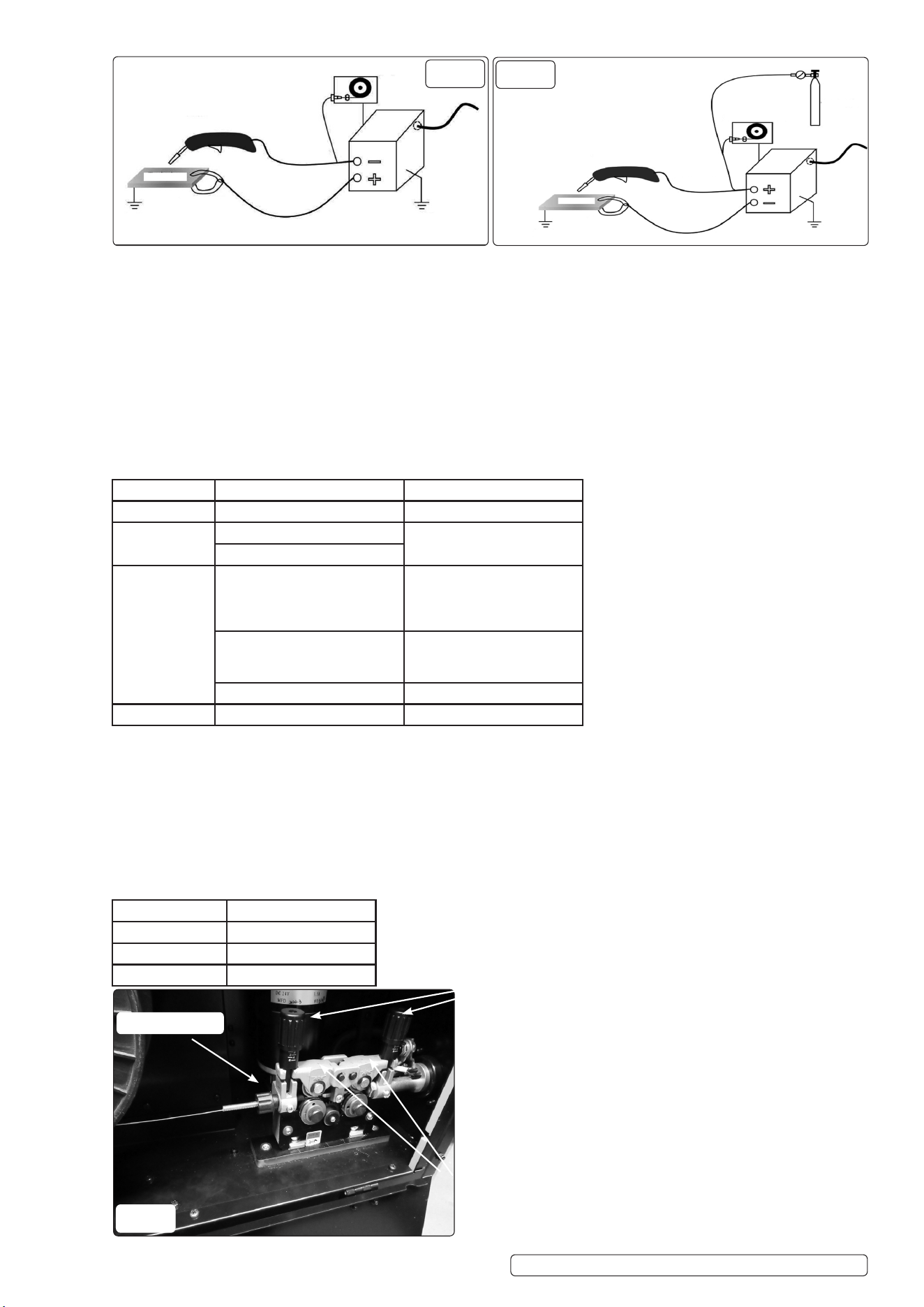
5.1. Beforeweldingorcutting,therststepistodeterminewhichtoolsareneededandhowtomakethecorrectconnections.Ifthepolarity
isincorrectlyconnected,itcaneasilydamageweldingorcuttingtools(especiallyweldingtorches),anditmayalsoresultinpoor
welding quality.
5.2. ESTABLISHING THE ELECTRICAL CONNECTIONS
Original Language Version
© Jack Sealey Limited
Model No POWERMIG500i
Welding Current 50-500A
Wire Capacity 5-15kg(0.6-1.6mm)
Eceincy 0.8
Electrode Capacity 1.6-5mm
Duty Cycle MIG 60% @500A 100% @ 388A
Duty Cycle MMA 60% @ 500A 100% @ 388A
Duty Cycle TIG 60% @ 500A 100% @ 388A
Gas Type CO2, Argon, CO2/Argon Mix
MigTorch(inc) 3mEuroNon-LiveBinzel
Absorbed Power 19.04kW
No Load Voltage 82V(MMA),82V(MIG)
Supply 415V~ 3ph
Power Supply Cable Length 2m
Weight POWERMIG500i 42.5kg
Weight POWERMIG500Wi 55.7kg
EMCClassication Class A.
Input Current 39A(MMA),38A(MIG)
Output Voltage 50A/22Vto500A/40V(MMA),
30A/15.5Vto500A/39V(MIG)
IP Rating IP21S
POWERMIG500i POWERMIG500Wi Issue:2 12/03/25
TIG
Fig. 1
Welding Rod
Fig. 2
MMA
Electrode
Mode Tools Workpeice
polarity
Torch polarity
MMA Grounding clamp
Welding torch
Negative Positive
TIG Grounding clamp
TIG Welding torch
Argon cylinder
Positive Negative
MIG/MAG Grounding clamp
MIG Welding torch
Cylinder
Negative Positive
FLUX CORED Grounding clamp
FLUX CORED Welding torch
Positive Negative
Grounding clamp
FLUX CORED Welding torch
Cylinder
Negative Positive
Description Part No.
1 Earthclampset2m(notshown) POWERMIG500Wi-99
1 Gashose3m(notshown) POWERMIG500Wi-100
1 Electrodeholderset2m(notshown) POWERMIG500Wi-101
1 Powercable2m(notshown) POWERMIG500Wi-102
1 3MigTorch3m(notshown) POWERMIG500Wi-103
1 Signalconnectioncable(notshown) POWERMIG500Wi-104
1 Powerconnectioncable(notshown) POWERMIG500Wi-105
1 EuromigTorch3m(notshown) POWERMIG500i-85
5.3. INSTALLATION STEPS
5.3.1. Makesurethemachineisturnedo.
5.3.2. Checkwhetherthepowercableisingoodconditionandtheinputvoltageiscorrect.
5.3.3. Connect to the input power source.
5.3.4. If necessary, select the appropriate gas and connect it.
5.3.5. For MIG/MAG/Flux-Cored welding, ensure the wire feeder is properly connected.
5.3.6. Makesuretheworkpieceisrmlyconnectedaccordingtothecorrectpolarity.
5.3.7. Connect the welding torch according to the correct polarity.
5.3.8. Turn on the machine.
5.3.9. Select the correct welding mode on the screen and adjust the appropriate parameters.
5.3.10. Before starting, ensure there is no short circuit formed between the torch and the workpiece.
5.4. CHOOSE THE CORRECT GAS
5.4.1. Beforewelding,it’snecessarytousegastoprotecttheworkpiece.Selectingthecorrectgasiscrucialforachievingqualitywelding
results.
5.4.2. WIRE FEEDER (Fig.5)
5.4.3. Releaseidlerarmsbyunscrewingtheidlerarmclamps(Fig.5)
5.4.4. Selecttheappropriatewirefeedwheelforinstallationandfittodriveshaftusingthesuppliedfittings.
5.4.5. Install a suitable diameter reel of suitable material by unscrewing the turn wheel and locating the reel onto the shaft.
5.4.6. Thread a suitable diameter of wire through the wire feed mechanism.
5.4.7. Lockidlerarmsusingtheclamps(Fig.5).
5.4.8. Adjustfeedtensioner(Fig.5)asnecessary.
5.4.9. Thermalcontrolcanbeacheivedadjustingeithervoltage,currentorfeedspeed.
5.4.10. Thediameteroftheweldingwire,wirefeedwheelandandthetypeoftheconductivenozzleshouldbethesame.
5.5. SELECTING THE CORRECT WIRE FEED
POWERMIG500i POWERMIG500Wi Issue:2 12/03/25
Original Language Version
© Jack Sealey Limited
Mode Material Gas
MMA Steel Not required
TIG DC TIG:Steel, Stainless steel Pure argon
AC TIG: Aluminum
MIG/MAG Steel 20% CO2 +80% argon or
Pure CO2
25% CO2 +75% argon
10% CO2 +90% argon
Stainless steel 2% CO2+98% argon or tri-
mix gas
2% O2+98% argon
Aluminium Pure argon
FLUX CORED Steel Not required
Feed Wheel Type Welded materials
U-shaped wheel Aluminium only
Knurled wheel Flux cored welding wire
V-shaped wheel Steel, Stainless steel
Idler Arm Clamps
Idler Arms
Fig. 5
Fig. 3
FLUX
CORED
Fig. 4
MIG/MAG
Feed Tensioner
Original Language Version
© Jack Sealey Limited
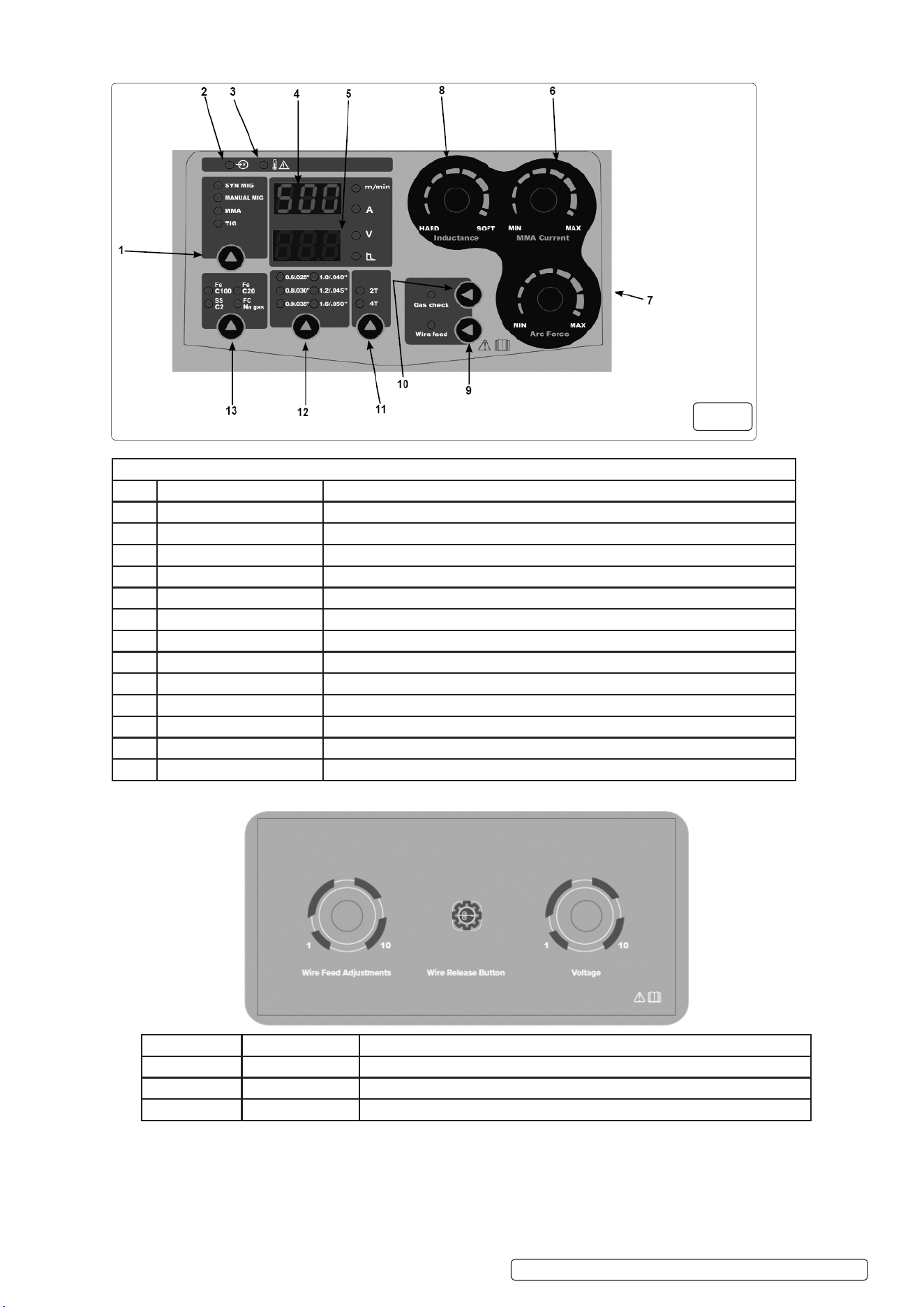
Key to Fig. 6
ITEM Description Function
1 Mode Button Select mode
2 LED Power light
3 LED Overheatindication
4 Display 1 ShowthevalueofwirespeedinMIGmodeandcurrentinMMA&TIGmodes
5 Display 2 ShowthevalueofvoltageinMIGmodeandarcforceinMMAmode
6 Wire speed ¤t Knob AdjustthevalueofwirespeedinMIGmodeandcurrentinMMA&TIGmodes
7 Voltage & arc force Knob AdjustthevalueofvoltageinMIGmodeandarcforceinMMAmode
8 Inductance Knob Adjustthevalueofinductance
9 Inching button Inching
10 Gas button Gas check
11 2T/4T button Select 2T/4T function
12 Wire diameter button Select the diameter of wire in MIG mode
13 Material button Select the material in MIG mode
POWERMIG500i POWERMIG500Wi Issue:2 12/03/25
5.6. MAIN CONTROL PANEL
5.7. WIRE FEEDER CONTROL PANEL
5.8. SHORT CIRCUIT PROTECTION
5.8.1. Whenashortcircuitisdetected,themachinewillturnotheoutputcurrenttoavoidbeinginahighcurrentoutputstateallthetime.
Sometimestheoutputcurrentmaystillexist,andtheusershouldavoidshortcircuitbetweentheelectrodeandtheworkpieceasmuch
aspossible,anddonotgettooclose,especiallythealkalineelectrode.Ifthereisashortcircuit,itshouldbequicklyremovedfromthe
shortcircuitstate,andifnecessaryandconvenient,itcanbeshutdownrstandthenprocessed.
Fig. 6
No Name Adjustments
1 Control knob 1 Adjust the wire feeding speed in MIGSYN & MIG modes
2 Inching button Press for wire feeding before welding in MIGSYN & MIG mode
3 Control knob 2 AdjusttheoutputvoltageinMIGSYN&MIGmodes

5.9. 2T/4T TRIGGER CONTROLS
5.9.1. 2T/4Taretwowaysofon-ocontrolofwelders.
2T/4T is commonly used for TIG, MIG, and PLASMA CUTTING.
5.9.2. 2T/4TWORKINGMETHODS
5.10. PRE GAS AND POST GAS
5.10.1. Beforestartingtheweldingwork,closetheweldingtorch,andthemachinewillbegintodelivergas,whichisthepregas.Thefrontair
supplyensuresthattheweldingisinaprotectivegasatmosphereandimprovestheweldingquality.
Aftertheendofthewelding,donotimmediatelyremovethetorch,thetorchcontinuestotransportasectionofgas,whichhelpsto
reducethetemperatureoftheweldmentsurface,butalsotoavoidthehigh-temperatureworkpieceandairchemicalreaction.
5.11. SYN—JUST FOR MIG/MAG
5.11.1. SYN means synergy. The essence of synergy is that after testing, we get suitable welding parameters, and write it into the software,
when you need to query welding parameters, you do not need to ask and query, only need to select certain parameters on the panel,
andtheweldingmachinewillrecommendtheappropriateweldingcurrent(andweldingvoltage).
5.11.2. However,everyone’sfeelandthespeedoftheweldingmachinevary,soalthoughwerecommendthecurrent(andvoltage),youcan
stilladjustonthisbasis,onlynetuningisrecommended.
5.12. MMA (ARC FORCE)
5.12.1. When the electrode is too close to the workpiece, the machine will increase the output current. The electrode will melt faster.
5.12.2. ARCFORCEhelpspreventshortcircuits.
5.13. MIG/MAG (INDUCTANCE)
5.13.1. Thehardnessofweldingarccanbechangedbyadjustingtheinductance.Thesmallertheinductancevalueis,theharderthewelding
arcisandthebiggerthesplashis.Thehighertheinductancevalue,thesofterthearcandthesmallerthesplash.
5.14. WELDING PROCEDURE
5.14.1. Specify the material to be welded, the thickness, and the welding mode to be used.
5.14.2. Selectappropriatetoolingformodetobeused(Section5).
5.14.3. Connectthepowerline,gas,wireorelectrodeandwelding/cuttingtorch,andturnon(seeFig.1,Fig.2,Fig.3,Fig.4)
5.14.4. Select the appropriate mode on the screen.
5.14.5. Adjustthecurrent(orvoltage,wirefeedspeed)tobeusedinweldingorcutting.
5.14.6. Determine the process to be used when welding, such as 4T mode, pulse, etc.
5.14.7. Start welding or cutting.
5.14.8. Duringtheweldingprocess,thecurrentorvoltage,wirefeedspeedandprocessparameterscanbeadjustedaccordingtothe
weldingeectuntilasatisfactoryweldingeectisobtained.
5.14.9. Forthemachinewithpostgasfunction,whentheweldingworkisnished,theweldingtorchshouldnotleavetheworkpiece
immediately, and the post gas should be completed.
8 DO NOT immediately touch the workpiece and welding torch.
5.14.10. Turnothepower,turnothegas,cleanuptheweldingmachine,andkeepitsafe.
5.15. MIG/MAG/FLUX CORED
5.15.1. Thediameteroftheweldingwire,thediameterwirefeedwheelandthediameteroftheconductivenozzleshouldbethesame.
5.15.2. Thenozzleattheheadofthetorchplaysaprotectiverolefortheconductivenozzle,andconfirmthatithasbeeninstalledbefore
welding.
6. FAULT CODES
6.1. If the machine stops working, please refere to these fault codes.
Original Language Version
© Jack Sealey Limited
2T Press the welding torch and the machine starts to work;
Release the torch and the machine stops working.
4T Presstheweldingtorchforthersttime,andthemachineentersthe
initial current;
Loosen the welding torch, the machine enters the working current,;
Press the welding torch again, the machine enters the end up current;
Loosen again and the machine stops working.
POWERMIG500i POWERMIG500Wi Issue:2 12/03/25
Fault Description
E01/F01 Overheating
E02/F02 Theinputvoltageisoverorundervoltage
E05/F05 Torch switch closed before turning on
E08/F08 Overcurrent
E09/F09 Theoutputisshort-circuitedorthevoltagefeedbacklineisabnormal
E10/F10 Closed torch, no output
E11/F11 Communication exception
E12/F12 The wire feeder is abnormal
E13/F13 Abnormaloutputcurrent(outputcurrentlessthansetvalue)

6.2. COMMON TROUBLES AND SOLUTIONS
7. MAINTENANCE.
WARNING! Disconnect from power supply before carrying out any maintenance procedures.
8 DO NOT take apart the machine without permission, it may damage the machine.
9 Whenmovingthemachine,makesurethepowerisoff.
8 DO NOTblockthefanoftherunningmachineortouchthefanposition.Checktheventilationbeforeeachuse.
9 Always start by reading the manual for your specific welding equipment.
9 Regularlycleanyourweldingequipmenttoremoveanydirt,debris,ormetalshavingsthatcouldclogupthemachinery.Useasoftbrush
orcompressedairtocleananycoolingfans,vents,orfilters.
9 Inspect the welding cables regularly for any damage or wear and tear. Replace any cables that show signs of damage, such as fraying, s,
or cracks.
9 Check the consumables, such as tips, nozzles, and electrodes, regularly for wear and tear. Replace any consumables that are damaged
orwornout.Usingdamagedconsumablescannegativelyaffectthequalityofyourwelds.
9 Check the gas cylinder regularly for pressure and leaks. Replace the gas cylinder if it is empty or damaged.
9 Whennotinuse,storeyourweldingequipmentinaclean,dry,andsafelocation.Keeptheequipmentcoveredtoprotectitfromdust,
moisture,andotherenvironmentalfactors.
9 Check the welding machine output wiring specifications, firmness, and the cable connection screws for rust and oxidation.
8 DO NOTshort-circuittheconductivenozzleandtheworkpiece.Theshortcircuitwillburnouttheconductivenozzle.Onceburnedout,it
needs to be replaced, otherwise it will affect the welding quality.
WARNING!Ensuretheunitisdisconnectedfromthemainspowersupplybeforeperforminganymaintenanceorservice.
9 Regularly check all welding cables and secondary terminals to ensure they are in good order and connected correctly, also check
during welding to ensuretheyarenotoverheating.
9 Check that the gas hose connections are tight and that there are no gas leaks.
7.1. WIRE FEED UNIT
7.1.1. Checkthewirefeedunitatregularintervals.Thefeedrollerwireguideplaysanimportantpartinobtainingconsistentresults.Poorwire
feedingaffectswelding.Cleantherollersweekly,especiallythefeedrollergroove,removingalldustdepositsfromthefeederarea.
7.1.2. CHANGINGFEEDROLLER/ROLLERSIMPORTANT: Set up the feed rollers according to the wire size required for the job in hand.
7.2. TORCH
7.2.1. Protect torch cable assembly from mechanical wear. Also do not allow the torch or its cable to come into contact with hot surfaces,
especially a hot workpiece as this would cause the insulating materials to melt, making the torch unsafe and unusable.
7.2.2. Make regular checks on the gas pipe and connector seals.
7.2.3. Everytimethewirereelischanged,blowoutthewire-guidehoseusingdrycompressedair(max.5bar)tomakesureitisnotdamaged;
7.2.4. Before using the welding machine, always check the torch terminal parts for wear and make sure they are assembled correctly: nozzle,
contact pipe, gas diffuser.
Original Language Version
© Jack Sealey Limited
POWERMIG500i POWERMIG500Wi Issue:2 12/03/25
Mode Fault Solution
All modes
E01/F01overheating Wait for the welder to cool down to return temperature, and then the welder will
continue to work.
E02/F02
Inputvoltageistoohighortoolow
Checkthepowersupplyandreplacethepowerinareasonablevoltage
E09/F09
Short-circuited
Firmly separate the welding torch from the workpiece and shut down the welding
machine if necessary.
Machine cannot be turned on Check whether the input line is intact, whether the power is turned on, and whether the
inputvoltageisnormal
E10/F10
Closed torch has no output
Check whether the ground cable and control cable are properly connected
Gas leaks Gas leaks can occur in welding machines, which can lead to poor quality welds.
Checkthegaslinesandttingsforleaks,andtightenorreplaceanyfaultyconnections.
It’simportanttoregularlyinspectthegaslinesandttingsforwearandtear,and
replace them if necessary.
Arc instability Check the ground connection, adjust the settings according to the type of material
being welded, and replace the electrode if necessary.
The workpiece is welded
Through
Reduce current.
MMA
Arcingdiculty Increase the current;
IncreaseHOTSTART;
Dried electrode.
Welding rod adhesion Increase the current;
Increase ARC FORCE.
Welding arc break Shorten the distance between the electrode and the workpiece, do not pull too high.
TIG
The weld colour is dark Accelerate the speed of welding;
DO NOTremovethetorchimmediatelyafterwelding;
Turn up the pre gas and post gas.
The tungsten needle burns
Out quickly
Check wiring polarity.
Irregular weld Sharpen the tungsten needle.
Weld failure Increase current.
7.3. CONTACT TIP Thecontacttipisaconsumableitemandmustbereplacedwhentheholebecomesenlargedoroval.Thecontacttip
MUST be kept free from spatter to ensure an unimpeded flow of gas.
7.4. GAS CUP
7.4.1. Tokeepthecontacttipfreefromspatter,werecommendtheuseofSealeyanti-spatterspray(MIG/722307)availablefromyourSealey
stockist.
7.5. INTERNAL MAINTENANCE / INSPECTION
INTERNALINSPECTIONANDMAINTENANCEOPERATIONSSHOULDBECARRIEDOUTONLYANDEXCLUSIVELYBYSKILLED
ORAUTHORISEDELECTRICAL/MECHANICALTECHNICIANS.
WARNING:BEFOREREMOVINGTHEWELDINGMACHINEPANELSANDWORKINGINSIDETHEMACHINEMAKESURETHE
WELDINGMACHINEISSWITCHEDOFFANDDISCONNECTEDFROMTHEMAINPOWERSUPPLYOUTLET.
7.5.1. Ifchecksaremadeinsidetheweldingmachinewhileitislive,thismaycauseseriouselectricshockduetodirectcontactwithliveparts
and/orinjuryduetodirectcontactwithmovingparts.
7.5.2. Inspecttheweldingmachineregularly,withafrequencydependingonuseandthedustinessoftheenvironment,andremovethedust
depositedonthetransformer,reactanceandrectifierusingajetofdrycompressedair(max.10bar).
7.5.3. DO NOTdirectthejetofcompressedairontheelectronicboards;thesecanbecleanedwithaverysoftbrushorsuitablesolvents.
7.5.4. At the same time make sure the electrical connections are tight and check the wiring for damage to the insulation.
7.5.5. At the end of these operations re-assemble the panels of the welding machine and screw the fastening screws right down.
WARNING: Never,evercarryoutweldingoperationswhiletheweldingmachineisopen.
8. END OF LIFE
8.1. DisposeofunitandaccessoriesinaccordancewithLocalandNationalregulations,WEEERegulationsandEnvironmentProtection
footers.
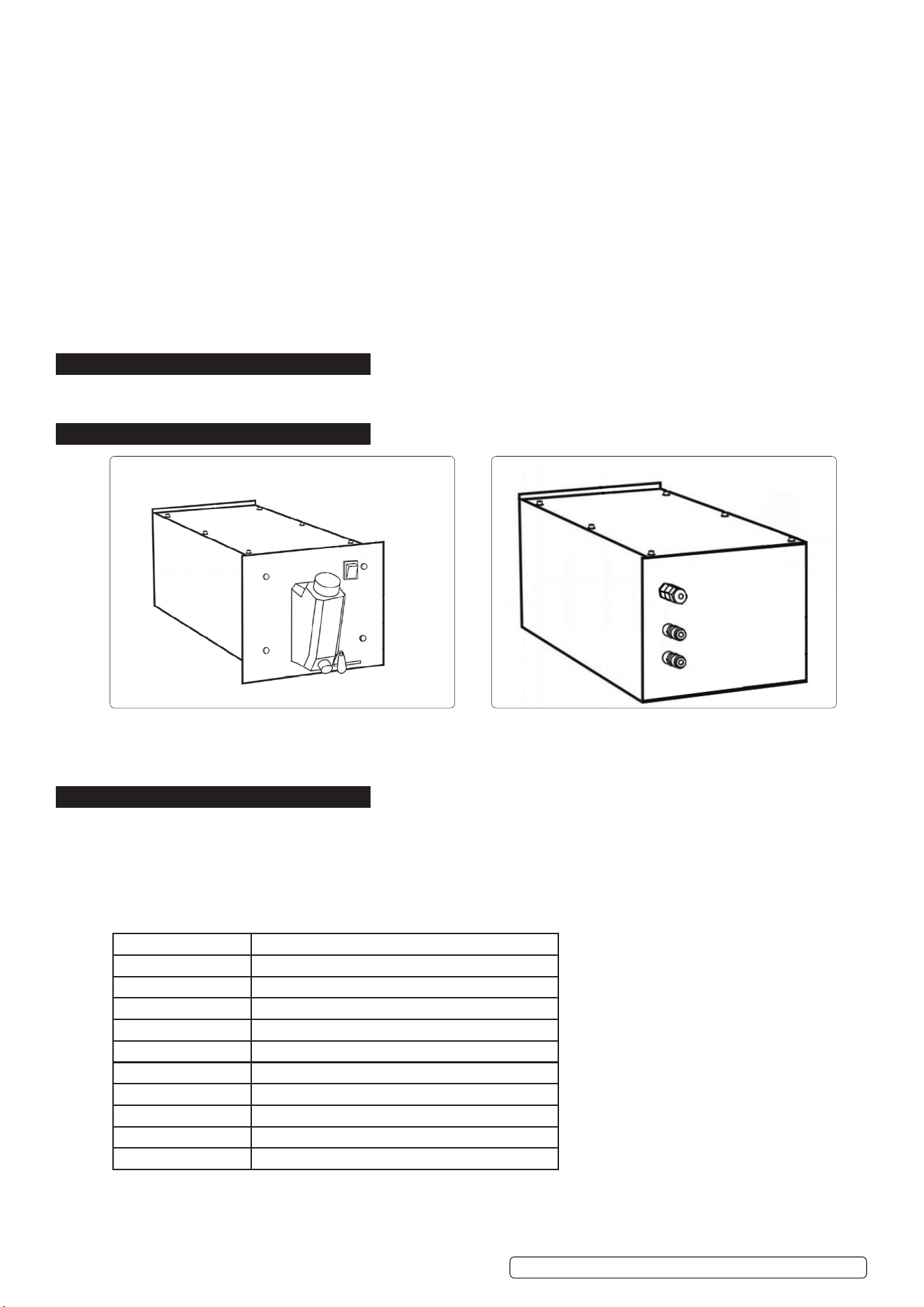
9. WATER COOLER POWERMIG500WI
1. Metal housing
2. Cooling liquid tank
3. On/Off button
4. Fixed key
10. WATER COOLER FUNCTIONS
10.1.1. Increasethestableoperatingtimeofweldinginverters.
10.1.2. Providehighvoltagewithinarangeof17meters.
10.1.2.1. The cooler casing is corrosion-resistant.
10.1.3. Low noise.
10.1.4. Easy to operate.
10.1.5. Improvetheperformanceanddurabilityofweldingmachines.
10.1. WATER COOLER SPECIFICATIONS
5. Signal connector
6. Cooling liquid outlet connector 1
7. Cooling liquid outlet connector 2
Original Language Version
© Jack Sealey Limited
POWERMIG500i POWERMIG500Wi Issue:2 12/03/25
1
2
3
4
5
6
7
Power 370W
Required current 0.3-0.6A
Maximum pressure 3kg/cm²
Feed rate 8L/min
Powersupplyvoltage 230(1phase)V
Operating conditions -20 -- 40
0
C
Tank capacity 6L
Coolant Distilledwater(atnegativetemperature-antifreeze)
Protectionlevel IP21
External dimensions 580 * 265 * 288mm
Weight 15kg
FRONT
REAR

11. DESIGN AND WORKING PRINCIPLES
11.1. Liquidcoolingissuitableforintensiveworkandhigh-temperatureenvironments.Forexample,iftheenvironmentis+30°Corhigher,the
hotaircirculationisnotsufficienttocooltheequipment.Inadditiontothefan,aliquidcoolingsystem(coolanttank)isalsoinstalled.It
contains a liquid or distilled water with special chemical components. Due to the circulation of coolant through the machine and welding
burner, it ensures continuous operation and cooling. This cooling method also optimizes the cooling of the welding burner. It is important
to remember that this type of equipment uses liquid cooled welding burners!
11.2. The main requirements for liquid cooling systems are:
11.2.1. Thelevelofcoolantmustbemonitored.Iftheliquiddecreases,theequipmentandburnerwillnothavesufficientcooling.
11.2.2. ItisprohibitedtomixliquidsfromdifferentmanufacturerstogetherbecauseThedevicemayfailduetodifferentchemicalcompositions
11.2.3. Regularly check the quality of the liquid.
12. EQUIPMENT CONNECTION
12.1. Removethedevicefromthepackaging.
12.2. Check the integrity of the equipment and accessories before use.
12.3. Openthefillingcap(hole)toensurethatthewatertankisclean.Althoughthewatertankandliquiditselfarecompletelyisolatedfromthe
environment,sometimesthesystemmaymalfunction
12.4. Thecoolingprocessisfilledwithdirt.Dirtmayenterliquidsforvariousreasons,suchaspouringliquidsfromdirtycontainers.Ifdirtenters
the liquid, it may interfere with the pump’s operation and needs to be cleaned.
12.5. Install the liquid cooling system on the welding machine trolley instead of the toolbox and connect it to the welding machine.
12.6. Connectthewatercirculationpipefromthecoolingdevicetothewiresupplydevice.Itisimportanttoconnectthepipesaccordingto
colour, from blue to blue and from red to red. The blue circuit is the output circuit of the cooling water after the radiator, and the red circuit
is the output circuit. The hot water is discharged from the power cable of the burner.
12.7. Protect it from direct water and sunlight.
12.8. Ensure that there is sufficient space for air circulation in front and behind the equipment.
12.9. Connectthewatercoolingdevicecabletothepowergrid.
12.10. If necessary, use accessories to connect the water supply hose to the connector.
12.11. Input, output. Connect the outlet of the liquid cooling unit to the inlet of the burner, and connect the outlet of the burner to the inlet of the
liquid cooling unit.
12.12. Fill the water tank with water. Another type of antifreeze can also be used. When using alcohol, the ratio of distilled water is 90% and
10%.
12.13. Controlthepouringlevelofthesemitransparentprotrudingpartofthefueltank.
12.14. Turn on the power.
12.15. Disconnecttheinletconnectoroftheliquidcoolingdevice,ensurethatthewatercircuitoftheburnerisfilledwithwater,andliquidflows
out from the outlet of the burner. Tighten the joint.
12.16. Thedeviceisready.
12.17. Checktheliquidlevelandrefillifnecessary.
12.18. Iftheliquidleveldropsorthehoseisblockedordamaged,weldingisnotallowed.
13. MAINTENANCE
13.1. DAILY MAINTENANCE
13.1.1. List of required conditions for daily execution:
13.1.2. Checkthewaterlevel(ifnecessary,topupwithliquid).
13.1.3. Check the cables and connections. Tighten them or replace damaged parts.
13.2. MAINTAIN EVERY SIX MONTHS
13.2.1. Theseconditionsmustbemeteverysixmonths
13.2.2. Clean the dust and dirt in the equipment. Replace the coolant and clean the pipes and water tank with clean water.
14. TROUBLE SHOOTING
FAULT SOLUTIONS
Pump running No liquid enters; Canal blockage;
-Blow or replace blocked channels with compressed air.
Pumpcavitation Checkthesealingandwaterlevelofthejointorreplacethepump
membrane.
Pump malfunction Checkthepowersupplyvoltageandfuses.
Original Language Version
© Jack Sealey Limited
POWERMIG500i POWERMIG500Wi Issue:2 12/03/25
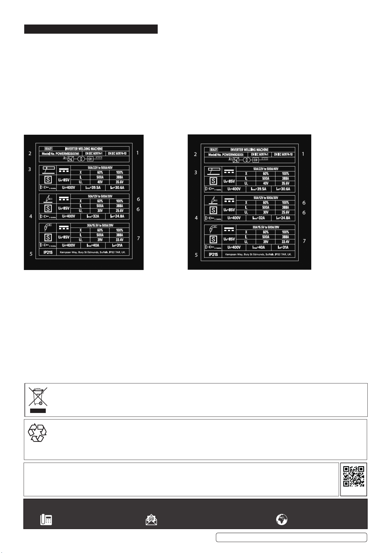
15. RATING PLATE
Onthefrontpanelofthewelderistheratingsplate,givingthefollowingdata:
1 - The BS/EU standard relating to the safety and construction of arc welding and associated equipment.
2 - Three phase transformer.
3-Symbolindicatesweldingwithacontinuousowofweldingwire.
4 - Symbol for three-phase AC supply.
5-Ratingofinternalprotectionprovidedbycasing.
6-OutputU0Ratedminimumandmaximumnoloadvoltage.
I2,U2Currentandcorrespondingvoltage.
X Welding ratio based on a 10 minute cycle.
20% indicates 2 minutes welding and 8 minutes rest,100% would indicate continuous welding.
7 - Mains Supply
U1Ratedsupplyvoltageandfrequency.
I1max Maximum current.
I1eMaximumeectivecurrent.
Original Language Version
© Jack Sealey Limited
Sealey Group, Kempson Way, Suffolk Business Park, Bury St Edmunds, Suffolk. IP32 7AR
01284 757500 sales@sealey.co.uk www.sealey.co.uk
ENVIRONMENT PROTECTION
Recycle unwanted materials instead of disposing of them as waste. All tools, accessories and packaging should be sorted, taken to
arecyclingcentreanddisposedofinamannerwhichiscompatiblewiththeenvironment.Whentheproductbecomescompletely
unserviceableandrequiresdisposal,drainanyfluids(ifapplicable)intoapprovedcontainersanddisposeoftheproductandfluids
according to local regulations.
Note:Itisourpolicytocontinuallyimproveproductsandassuchwereservetherighttoalterdata,specificationsandcomponentparts
without prior notice.
Important: No Liability is accepted for incorrect use of this product.
Warranty: Guarantee is 12 months from purchase date, proof of which is required for any claim.
WEEE REGULATIONS
DisposeofthisproductattheendofitsworkinglifeincompliancewiththeEUDirectiveonWasteElectricalandElectronicEquipment
(WEEE).Whentheproductisnolongerrequired,itmustbedisposedofinanenvironmentallyprotectiveway.Contactyourlocalsolid
waste authority for recycling information.
REGISTER YOUR
PURCHASE HERE
POWERMIG500i POWERMIG500Wi Issue:2 12/03/25