
QLX-D
QLX-D -- Wireless System
Version: 1 (2019-C)

Shure Incorporated
2/60
1.
2.
3.
4.
5.
6.
7.
8.
9.
10.
11.
12.
13.
14.
15.
16.
17.
18.
19.
20.
21.
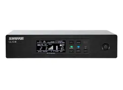
QLX-D
Wireless System
IMPORTANT SAFETY INSTRUCTIONS
READ these instructions.
KEEP these instructions.
HEED all warnings.
FOLLOW all instructions.
DO NOT use this apparatus near water.
CLEAN ONLY with dry cloth.
DO NOT block any ventilation openings. Allow sufficient distances for adequate ventilation and install in
accordance with the manufacturer’s instructions.
DO NOT install near any heat sources such as open flames, radiators, heat registers, stoves, or other
apparatus (including amplifiers) that produce heat. Do not place any open flame sources on the product.
DO NOT defeat the safety purpose of the polarized or grounding type plug. A polarized plug has two blades
with one wider than the other. A grounding type plug has two blades and a third grounding prong. The wider
blade or the third prong are provided for your safety. If the provided plug does not fit into your outlet, consult
an electrician for replacement of the obsolete outlet.
PROTECT the power cord from being walked on or pinched, particularly at plugs, convenience receptacles,
and the point where they exit from the apparatus.
ONLY USE attachments/accessories specified by the manufacturer.
USE only with a cart, stand, tripod, bracket, or table specified by the manufacturer, or sold with the apparatus.
When a cart is used, use caution when moving the cart/apparatus combination to avoid injury from tip-over.
UNPLUG this apparatus during lightning storms or when unused for long periods of time.
REFER all servicing to qualified service personnel. Servicing is required when the apparatus has been
damaged in any way, such as power supply cord or plug is damaged, liquid has been spilled or objects have
fallen into the apparatus, the apparatus has been exposed to rain or moisture, does not operate normally, or
has been dropped.
DO NOT expose the apparatus to dripping and splashing. DO NOT put objects filled with liquids, such as
vases, on the apparatus.
The MAINS plug or an appliance coupler shall remain readily operable.
The airborne noise of the Apparatus does not exceed 70dB (A).
Apparatus with CLASS I construction shall be connected to a MAINS socket outlet with a protective earthing
connection.
To reduce the risk of fire or electric shock, do not expose this apparatus to rain or moisture.
Do not attempt to modify this product. Doing so could result in personal injury and/or product failure.
Operate this product within its specified operating temperature range.
Explanation of Symbols
Caution: risk of electric shock
Shure Incorporated
3/60
•
•
•
•
Caution: risk of danger (See note.)
Direct current
Alternating current
On (Supply)
Equipment protected throughout by DOUBLE INSULATION or REINFORCED INSULATION
Stand-by
Equipment should not be disposed of in the normal waste stream
WARNING: Voltages in this equipment are hazardous to life. No user-serviceable parts inside. Refer all servicing to
qualified service personnel. The safety certifications do not apply when the operating voltage is changed from the
factory setting.
Important Product Information
LICENSING INFORMATION
Licensing: A ministerial license to operate this equipment may be required in certain areas. Consult your national
authority for possible requirements. Changes or modifications not expressly approved by Shure Incorporated could
void your authority to operate the equipment. Licensing of Shure wireless microphone equipment is the user’s
responsibility, and licensability depends on the user’s classification and application, and on the selected frequency.
Shure strongly urges the user to contact the appropriate telecommunications authority concerning proper licensing,
and before choosing and ordering frequencies.
Information to the user
This equipment has been tested and found to comply with the limits for a Class B digital device, pursuant to Part 15
of the FCC Rules. These limits are designed to provide reasonable protection against harmful interference in a
residential installation. This equipment generates uses and can radiate radio frequency energy and, if not installed
and used in accordance with the instructions, may cause harmful interference to radio communications. However,
there is no guarantee that interference will not occur in a particular installation. If this equipment does cause harmful
interference to radio or television reception, which can be determined by turning the equipment off and on, the user
is encouraged to try to correct the interference by one or more of the following measures:
Reorient or relocate the receiving antenna.
Increase the separation between the equipment and the receiver.
Connect the equipment to an outlet on a circuit different from that to which the receiver is connected.
Consult the dealer or an experienced radio/TV technician for help.

Shure Incorporated
4/60
•
•
•
•
•
•
•
•
•
This device complies with Industry Canada licence-exempt RSS standard(s). Operation of this device is subject to
the following two conditions: (1) this device may not cause interference, and (2) this device must accept any
interference, including interference that may cause undesired operation of the device.
Le présent appareil est conforme aux CNR d'Industrie Canada applicables aux appareils radio exempts de licence.
L'exploitation est autorisée aux deux conditions suivantes : (1) l'appareil ne doit pas produire de brouillage, et (2)
l'utilisateur de l'appareil doit accepter tout brouillage radioélectrique subi, même si le brouillage est susceptible d'en
compromettre le fonctionnement.
Note: EMC conformance testing is based on the use of supplied and recommended cable types. The use of other
cable types may degrade EMC performance.
Please follow your regional recycling scheme for batteries, packaging, and electronic waste.
WARNING: Danger of explosion if incorrect battery replaced. Operate only with AA batteries.
Note: Use only with the included power supply or a Shure-approved equivalent.
WARNING
Battery packs may explode or release toxic materials. Risk of fire or burns. Do not open, crush, modify,
disassemble, heat above 140°F (60°C), or incinerate.
Follow instructions from manufacturer
Only use Shure charger to recharge Shure rechargeable batteries
WARNING: Danger of explosion if battery incorrectly replaced. Replace only with same or equivalent type.
Never put batteries in mouth. If swallowed, contact your physician or local poison control center
Do not short circuit; may cause burns or catch fire
Do not charge or use battery packs other than Shure rechargeable batteries
Dispose of battery packs properly. Check with local vendor for proper disposal of used battery packs.
Batteries (battery pack or batteries installed) shall not be exposed to excessive heat such as sunshine, fire or
the like
Australia Warning for Wireless
This device operates under an ACMA class licence and must comply with all the conditions of that licence including
operating frequencies. Before 31 December 2014, this device will comply if it is operated in the 520-820 MHz
frequency band. WARNING: After 31 December 2014, in order to comply, this device must not be operated in the
694-820 MHz band.
Caution: Avoid operating mobile phones and mobile broadband devices near your wireless system to prevent the
possibility of interference.
WARNING: This product contains a chemical known to the State of California to cause cancer and birth defects or
other reproductive harm.
System Overview
QLX-D Digital Wireless delivers defined, streamlined performance with transparent 24-bit digital audio. Combining
professional features with simplified setup and operation, QLX-D offers outstanding wireless functionality for
demanding live sound events and installations.
®

Shure Incorporated
5/60
•
•
•
•
•
•
•
•
•
•
•
•
•
•
•
•
•
•
Shure digital wireless technology enables QLX-D to transmit clearly detailed audio with extended, virtually flat
frequency response. Designed to be highly RF spectrum efficient, QLX-D can operate more than 60 compatible
channels simultaneously in a single frequency band. Automatic channel scan and IR sync make finding and
assigning an open frequency quick and easy. Ethernet connection provides networked channel scanning across
multiple receivers and Shure Wireless Workbench control software compatibility for advanced frequency
coordination. AES-256 encryption comes standard and can be easily enabled for secure wireless transmission.
QLX-D also adds Shure rechargeable power options to provide dramatic long-term cost savings and extended
transmitter battery life over alkaline batteries, and battery metering that reports remaining runtime in hours and
minutes. With clearly defined performance and innovation, QLX-D delivers the very latest in digital wireless
technology from Shure.
Features
Transparent 24-bit digital audio
Extended 20 Hz to 20 kHz frequency range (microphone dependent)
120 dB dynamic range
Digital predictive switching diversity
64 MHz tuning bandwidth (region dependent)
More than 60 available channels per frequency band (region dependent)
Up to 17 compatible systems per 6MHz TV band; 22 systems per 8 MHz band
Easy pairing of transmitters and receivers over IR scan and sync
Automatic channel scan
Ethernet networking for multiple receiver systems
Network channel scanning configures open frequencies for networked receivers
Compatible with Shure Wireless Workbench 6 control software
Remote control from a mobile device or tablet via ShurePlus™ Channels app
AES-256 encryption for secure wireless transmission
Elegant and easy-to-use interface with high-contrast LCD menu
Compatible with external control systems such as AMX or Crestron
Professional-grade all-metal construction
Transmitters use 2 AA batteries or Shure SB900 rechargeable battery
®
Shure Incorporated
6/60
•
•
•
•
•
•
•
•
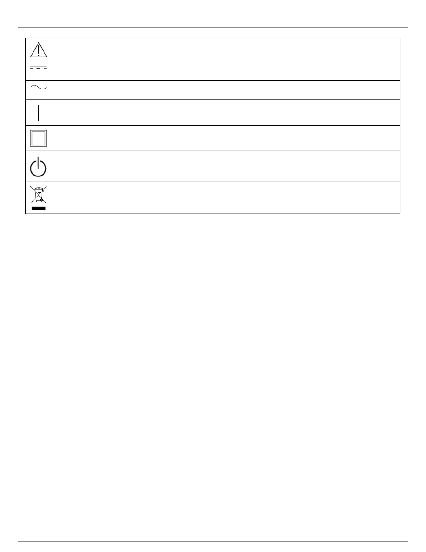
System Components
① QLXD4 Receiver
② PS24 Power Supply
③ 1/2 Wave Antennas (2)
④ 2 ft. BNC Cables with Bulkhead Adapters (2)
⑤ Choice of QLXD1 Bodypack Transmitter or QLXD2 Handheld Transmitter
⑥ AA Alkaline Batteries (not included in Argentina)
⑦ Rackmount Hardware
Model Variations
Model variations with additional components are available to meet specific performance situations.
QLXD2 Handheld Transmitter
Includes QLXD2 Handheld, available with any of the following microphone cartridges:
SM58
Beta 58A
SM86
Beta 87A
SM87A
Beta 87C
KSM9
KSM9HS (black)
Microphone Clip
Battery Contact Cover
Zipper Bag

Shure Incorporated
7/60
•
•
•
•
•
•
•
•
•
•
•
•
•
QLXD1 Bodypack Guitar System
Includes QLXD1 bodypack transmitter
WA305 Premium instrument cable
Zipper Bag
QLXD1 Bodypack Headworn or Lavalier
Includes QLXD1 bodypack, available with any of the following microphone cartridges:
Beta 98H/C
WL93
WL183
WL184
WL185
MX150 (omni)
MX150 (cardioid)
MX153 (black or tan)
SM35
Zipper Bag
Bodypack and Handheld Combo System
QLXD1 bodypack transmitter with WL185 Microflex cardioid lavalier microphone
QLXD2 handheld transmitter with Shure SM58 microphone cartridge
Battery Contact Cover
Zipper Bag (2)
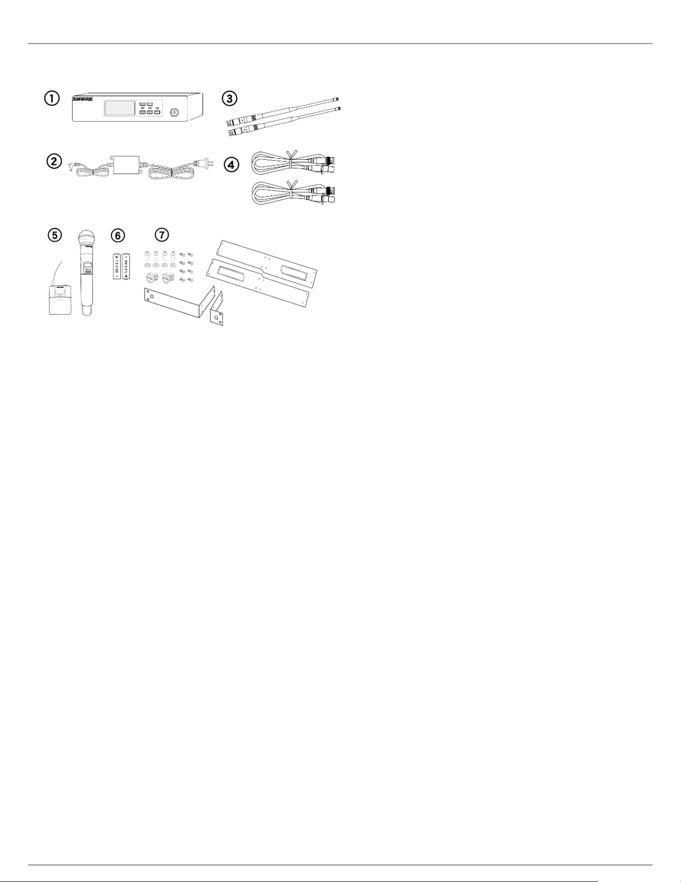
Quick Start
Step 1: Power and Antenna Connection
① Connect an antenna to each of the antenna connectors.
② Connect the power supply to the receiver and plug into an AC power source.
③ Connect the receiver audio output to a mixer or amplifier.
④ Press and hold the power button to turn on the receiver.
Shure Incorporated
8/60
1.
2.
Step 2: Scanning for the Best Available Channel
Press the menu button on the receiver to access the scan function.
Press the enter button to start a frequency scan. The scan icon will flash while in scan mode. When the scan
is complete, the selected group and channel appear on the display.
Step 3: Install Batteries into Transmitter
Shure Incorporated
9/60
•
•
1.
2.
3.
4.
1.
2.
① Accessing the Battery
Compartment
Press the side tabs on the bodypack or unscrew the cover on the handheld as
shown to access the battery compartment.
② Installing Batteries AA Batteries: Place batteries (note polarity markings) and AA Adaptor as
shown
Shure SB900 Battery: Place battery as shown (note polarity markings),
remove AA Adaptor from bodypack transmitter, stow AA Adaptor in door for
handheld transmitter
Note: If using AA batteries, select a battery type from the transmitter menu to ensure accurate battery metering.
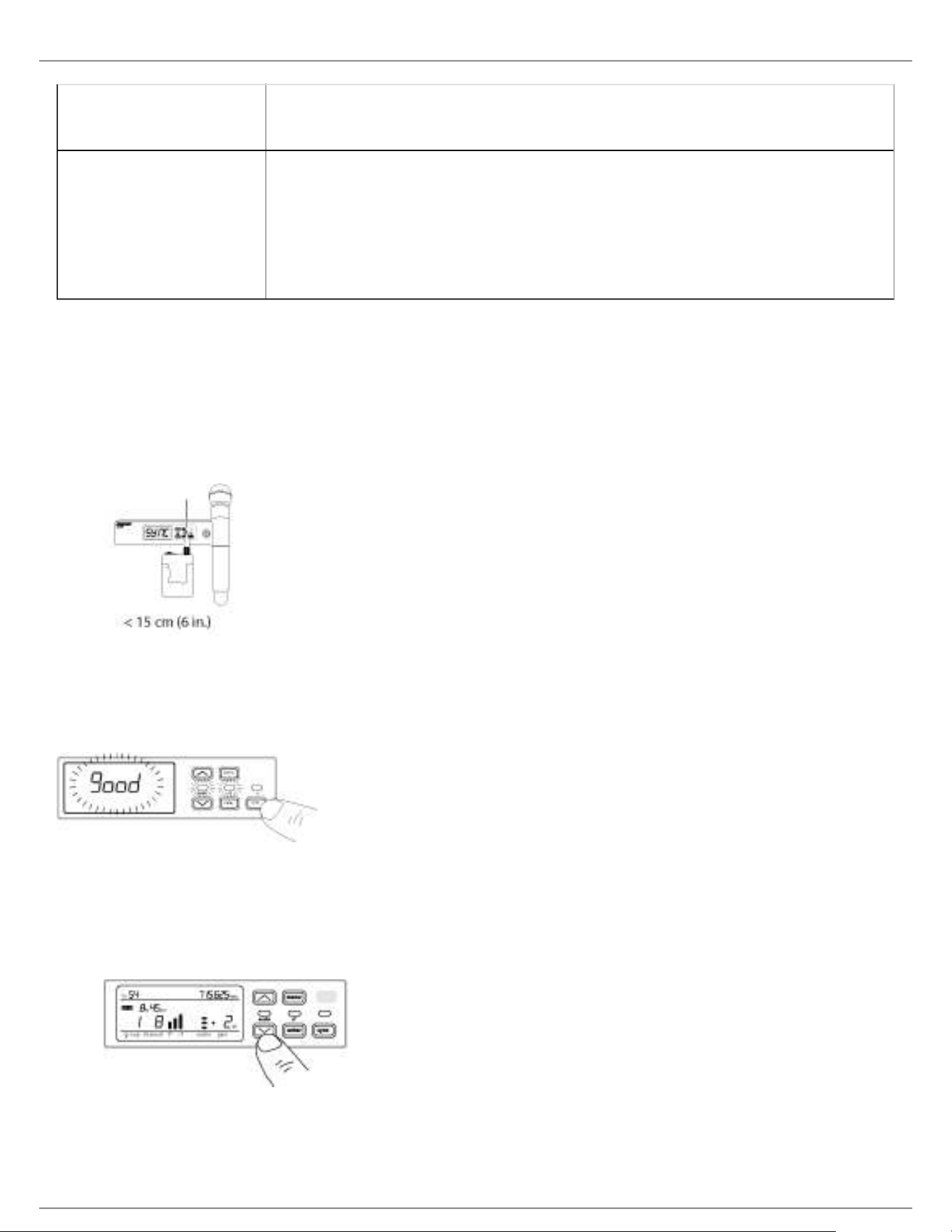
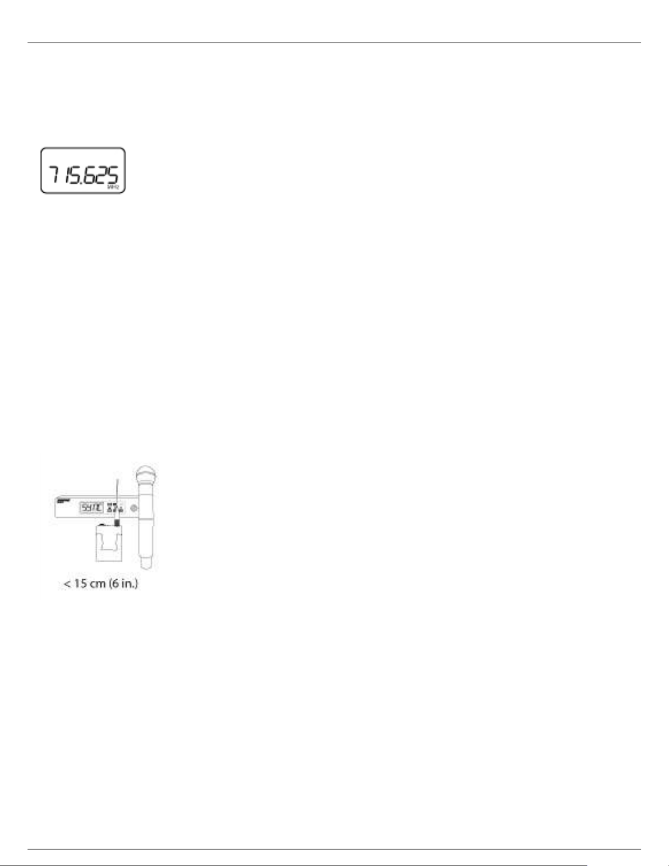
Step 4: IR Sync to Create an Audio Channel
Turn on the transmitter.
Press the sync button on the receiver. The red ir LED will blink indicating that sync mode is active.
Align the IR sync windows of the transmitter and receiver at a distance of <15 cm (6 in.). When the transmitter
and receiver are aligned, the red ir LED remains on and the sync will automatically occur.
sync good appears on the display when IR sync is complete. The blue rf LED will illuminate indicating that the
transmitter is within range of the receiver.
Note: If the IR sync fails, repeat the IR sync procedure, carefully maintaining alignment between the IR
windows of the transmitter and receiver.
Step 5: Sound Check and Gain Adjustment
Test the transmitter at performance levels while monitoring the audio meter and the audio LED. The audio
meter should display at least 3 bars and the audio LED should be green. Reduce the gain if there is audible
distortion of the audio.
Increase or decrease the gain if necessary by pressing the arrow buttons on the receiver front panel.
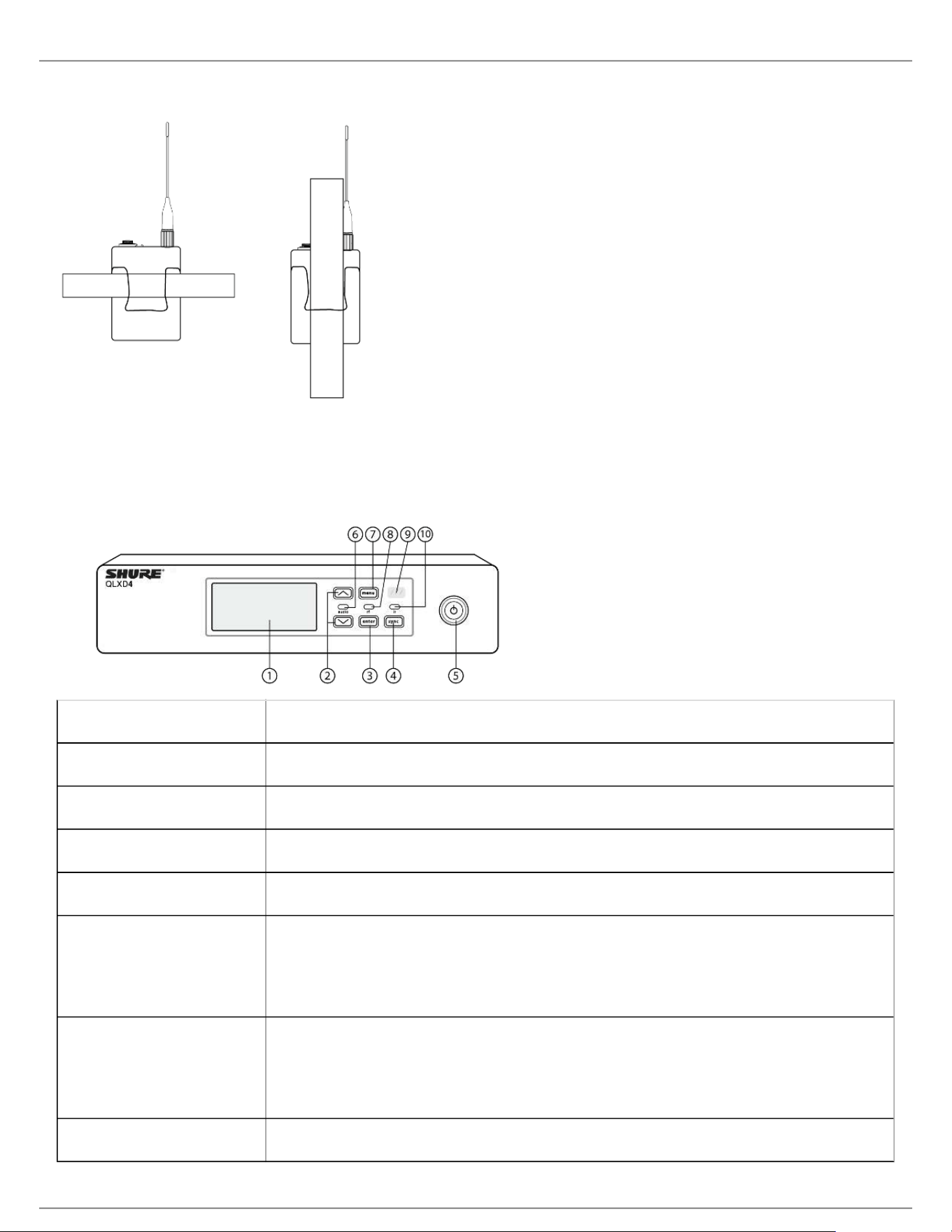
Wearing the Bodypack Transmitter
Clip the transmitter to a belt or slide a guitar strap through the transmitter clip as shown.
Shure Incorporated
10/60
•
•
•
•
•
•
For best results, the belt should be pressed against the base of the clip.
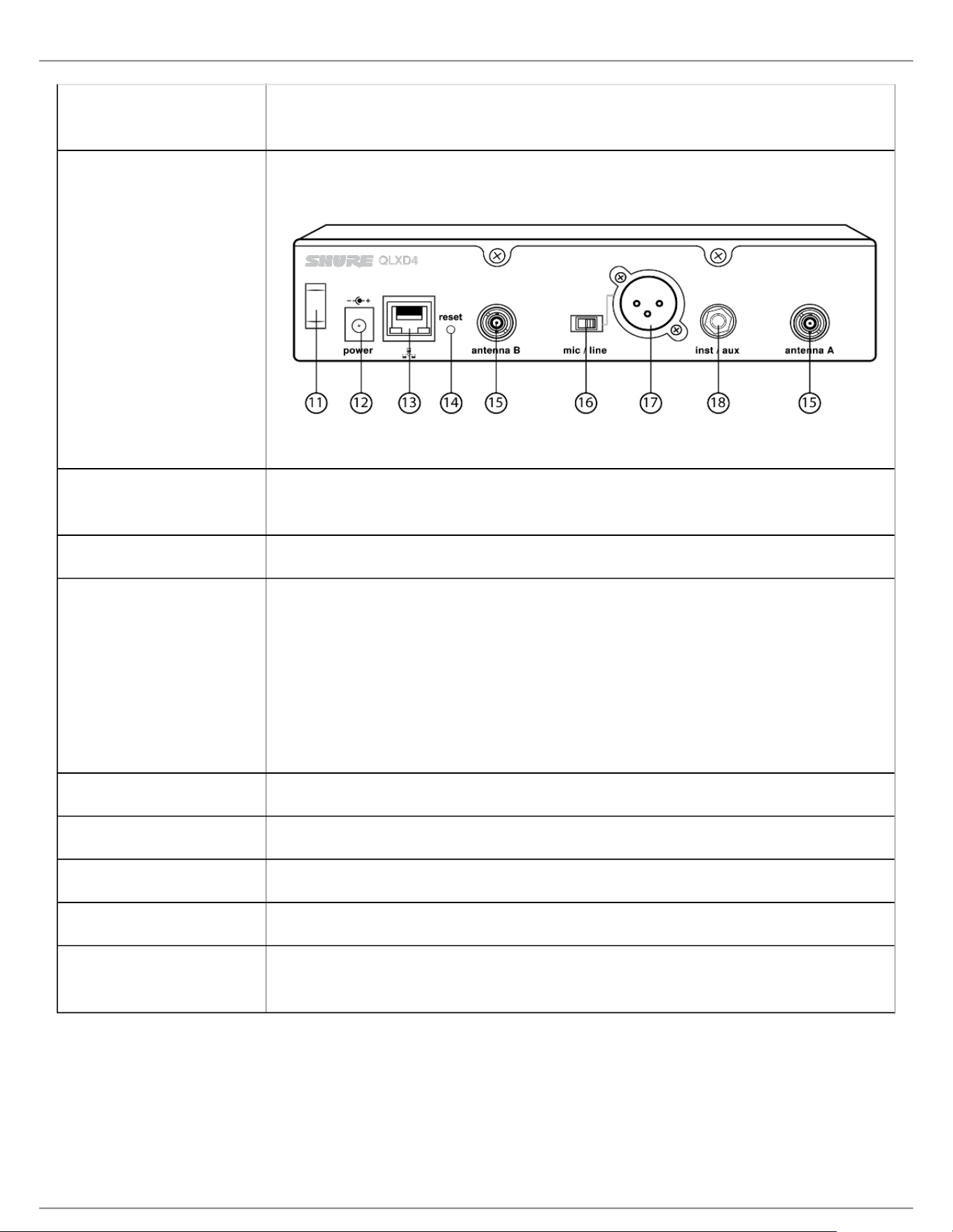
Hardware Interface
Receiver Front and Back Panels
① Display Shows menu options, receiver and transmitter settings.
② Arrow Buttons Adjust gain setting or change menu parameters.
③ Enter Button Press to save menu or parameter changes.
④ Sync Button Press to activate IR sync.
⑤ Power Switch Powers receiver on or off.
⑥ Audio LED Green = normal
Yellow = signal approaching limiter threshold
Red = limiter engaged to prevent clipping
⑦ Menu Button Press to access or select menu screens
Press to cancel pending changes
Press and hold to return to the home screen
⑧ RF LED Illuminates when RF link with transmitter is active.
Shure Incorporated
11/60
•
•
•
•
⑨ IR Window Align with the transmitter IR window during an IR sync to automatically program
transmitters.
⑩ Sync LED Blinking: IR sync mode is enabled
On: Receiver and transmitter aligned for IR sync
⑪ Power Cord Strain
Relief
Secures power cord.
⑫ Power Supply Jack Connection point for DC power supply.
⑬ Ethernet Port For network connection.
Amber LED (network speed):
off = 10 Mbps, on = 100 Mbps
Green LED (network status):
off = no network link, on = network link active
flashing = rate corresponds to traffic volume
⑭ Receiver Reset Press to restore receiver default settings.
⑮ Antenna Connectors BNC connector for receiver antennas
⑯ Mic/Line Switch Sets output level to microphone or line.
⑰ XLR Audio Output Balanced (1: ground, 2: audio +, 3: audio - )
⑱ 1/4" Instrument/
Auxiliary Output
Impedance Balanced (Tip: audio, Ring: no audio, Sleeve: ground)
Shure Incorporated
12/60
•
•
•
•
•
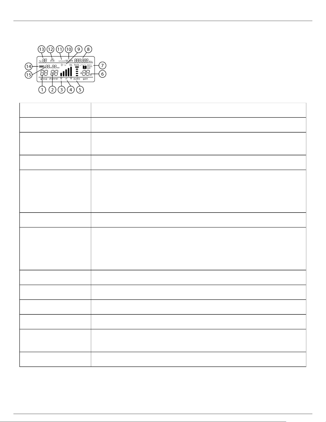
Receiver Display
① Group Displays group setting.
② Channel Displays channel setting.
③ Active Antenna
Indicator
Illuminates to indicate which antenna is active.
④ RF Signal Meter Number of bars displayed corresponds to RF signal level - OL = overload.
⑤ Audio Meter Number of bars displayed corresponds to audio level.
OL = Illuminates when receiver audio limiter is active to prevent clipping
TxOL = Illuminates when transmitter input is overloaded. Reduce input from
microphone or instrument to prevent clipping.
⑥ Gain Level Displays receiver gain setting in 1 dB increments.
⑦ Receiver Lock Status Lock icon and name of locked control:
menu
power
gain
⑧ Frequency Setting Selected frequency (MHz).
⑨ Encryption Status Illuminates when encryption is enabled.
⑩ Scan Displayed when scan function is active.
⑪ Network Scan Displayed when network scan function is active in multi-receiver systems.
⑫ Network Connection
Indicator
Illuminates when additional Shure components are detected on the network.
⑬ TV Channel Displays the number of the TV channel containing the selected frequency.
Shure Incorporated
13/60
⑭ Transmitter Battery
Icon
Indicates remaining battery life.
Enable the Low Battery Alert to flash the receiver display when battery runtime is
less than 30 minutes.
⑮ SB900 Battery
Runtime
When the transmitter is powered by a Shure SB900 rechargeable battery, remaining
runtime is displayed in hours:minutes.
Navigating the Receiver Menus
The receiver has a main menu for setup and configuration and an advanced menu to access additional receiver
functions.
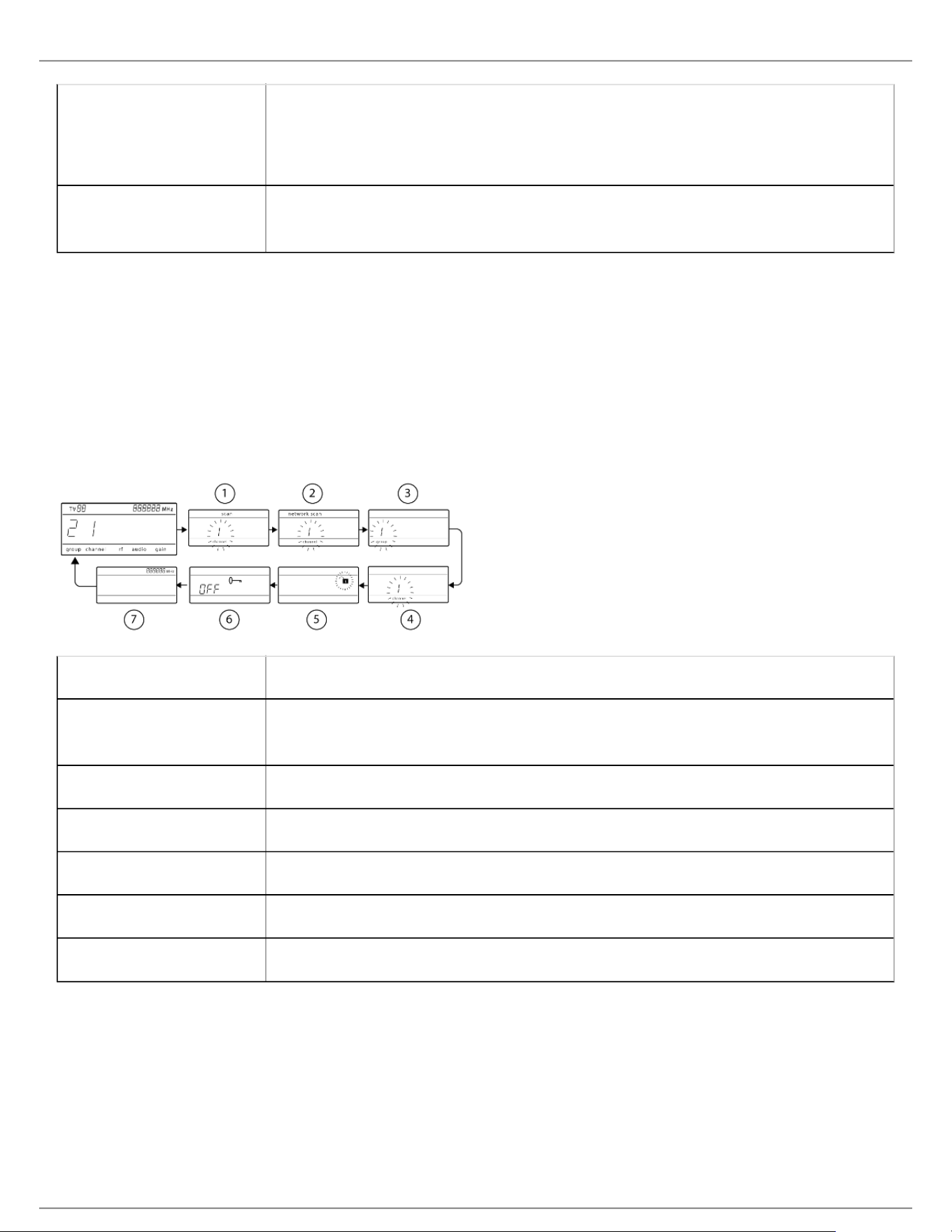
Main Menu
Press the menu button to access the menu. Each additional press of the menu button advances to the next menu
screen in the following order:
① Scan Receiver automatically scans for the best available frequency
② Network Scan Scans to find frequencies for networked receivers operating in the same frequency
band (available when connected to a network with receivers in the same band)
③ Group Edit the receiver group settings
④ Channel Edit the receiver channel settings
⑤ Lock Choose a control lock option
⑥ Encryption Use the arrow buttons to enable encryption (on) or disable encryption (off)
⑦ Frequency Use the arrow buttons to edit the frequency value
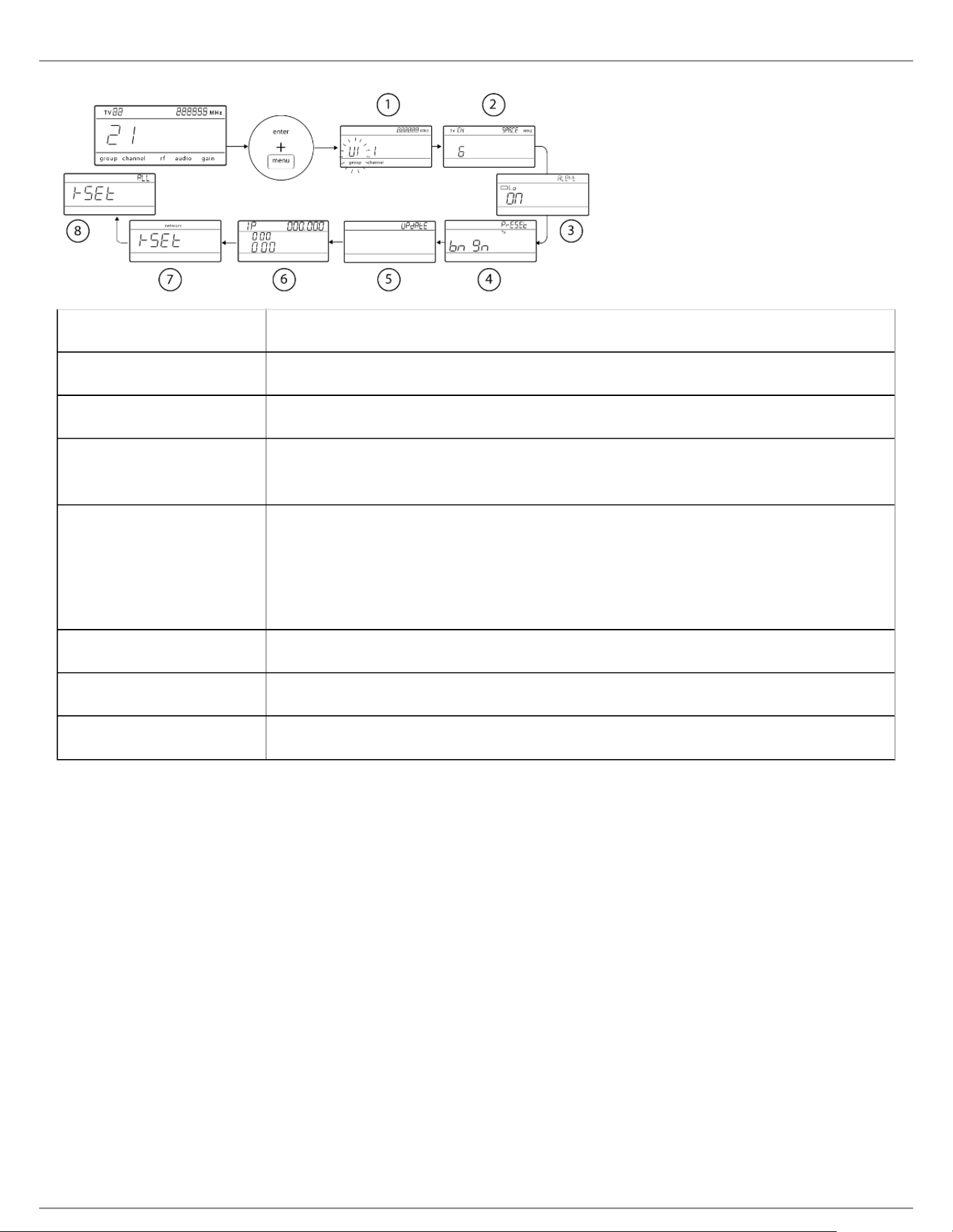
Advanced Menu
Starting from the main menu home screen, press menu while holding the enter button to access the advanced
menu. Each additional press of the menu button advances to the next menu screen in the following order.
Shure Incorporated
14/60
•
•
•
•
•
•
•
•
•
•
① Custom Groups Use to add channels and frequencies to Custom Groups
② TV Channel Spacing Selects the regional bandwidth for TV channel display
③ Low Battery Alert Enable or disable the low battery alert on the receiver screen
④ Boundary/Gooseneck
Transmitter Presets
Sends ULXD6/ULXD8 presets configured in WWB to transmitters via the IR Sync
window
⑤ Firmware Update Displays what kind transmitter firmware the receiver has available. See Firmware
Updates for more details.
HH BP = handheld or bodypack firmware
BN GN = boundary or gooseneck firmware
⑥ IP Settings Use to select and edit IP settings and subnet masks
⑦ Network Reset Returns network settings and IP address to default setting
⑧ Factory Reset Restores factory settings
For application and configuration details, see the related guide topic for each advanced feature.
Tips for Editing Menu Parameters
To increase, decrease or change a parameter, use the arrow buttons
A menu setting will blink when editing is enabled
To save a menu change, press enter
To exit a menu without saving a change, press menu
To access the advanced menu, press menu while holding the enter button from the home screen
To return to the home screen from any menu without saving changes, press and hold the menu button.
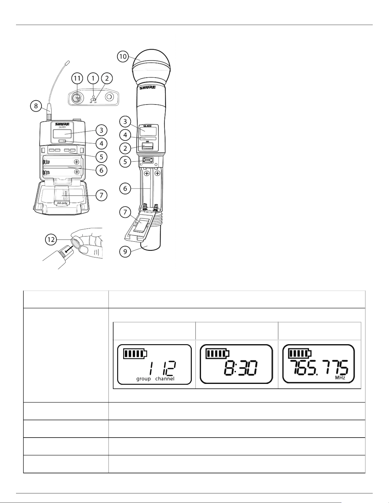
Transmitters
① Power LED
Green = unit is powered on
Red = low battery
② On/Off Switch

Shure Incorporated
15/60
Powers the transmitter on or off.
③ Display:
View menu screens and settings. Press any control button to activate the backlight.
④ IR window
Align with the receiver IR window during an IR sync for automated transmitter programming.
⑤ Menu Navigation Buttons
menu = Use to navigate between menu screens.
▼▲ = Use to select menu screens, edit menu parameters, or choose a home screen display option.
enter = Press to confirm and save parameter changes.
Tip: Press the menu button to exit without saving parameter changes.
⑥ Battery Compartment
Requires 2 AA batteries or a Shure SB900 rechargeable battery.
⑦ AA Battery Adapter
Secures batteries when powering transmitter with AA batteries instead of Shure SB900 battery.
⑧ Bodypack Antenna
For RF signal transmission.
⑨ Handheld Integrated Antenna
For RF signal transmission.
⑩ Microphone Cartridge
See Optional Accessories for a list of compatible cartridges.
⑪ TA4M Input Jack
Connects to a 4-Pin Mini Connector (TA4F) microphone or instrument cable.
⑫ Battery Contact Cover
Align the cover as shown to prevent reflections from the battery contacts during broadcasts or performances.
Shure Incorporated
16/60
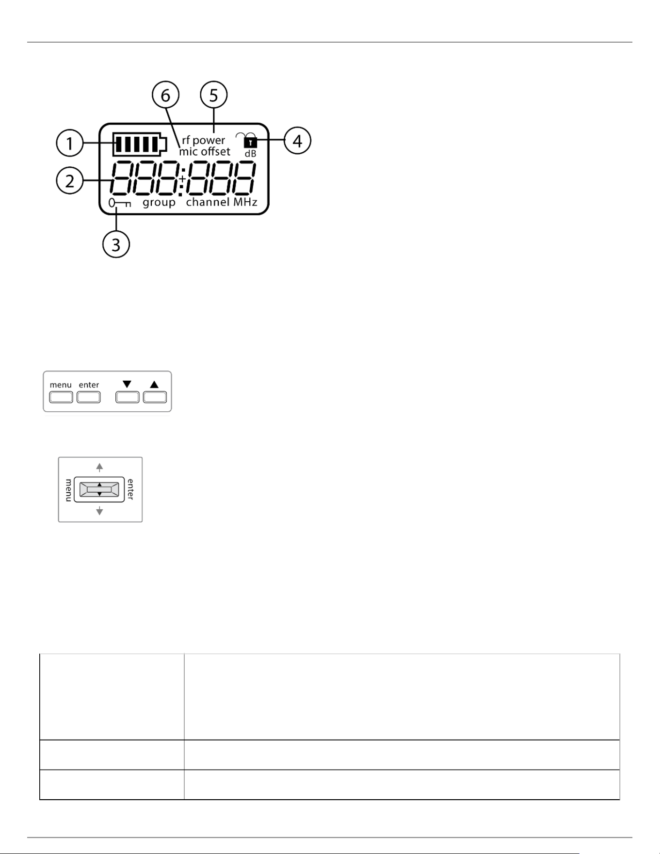
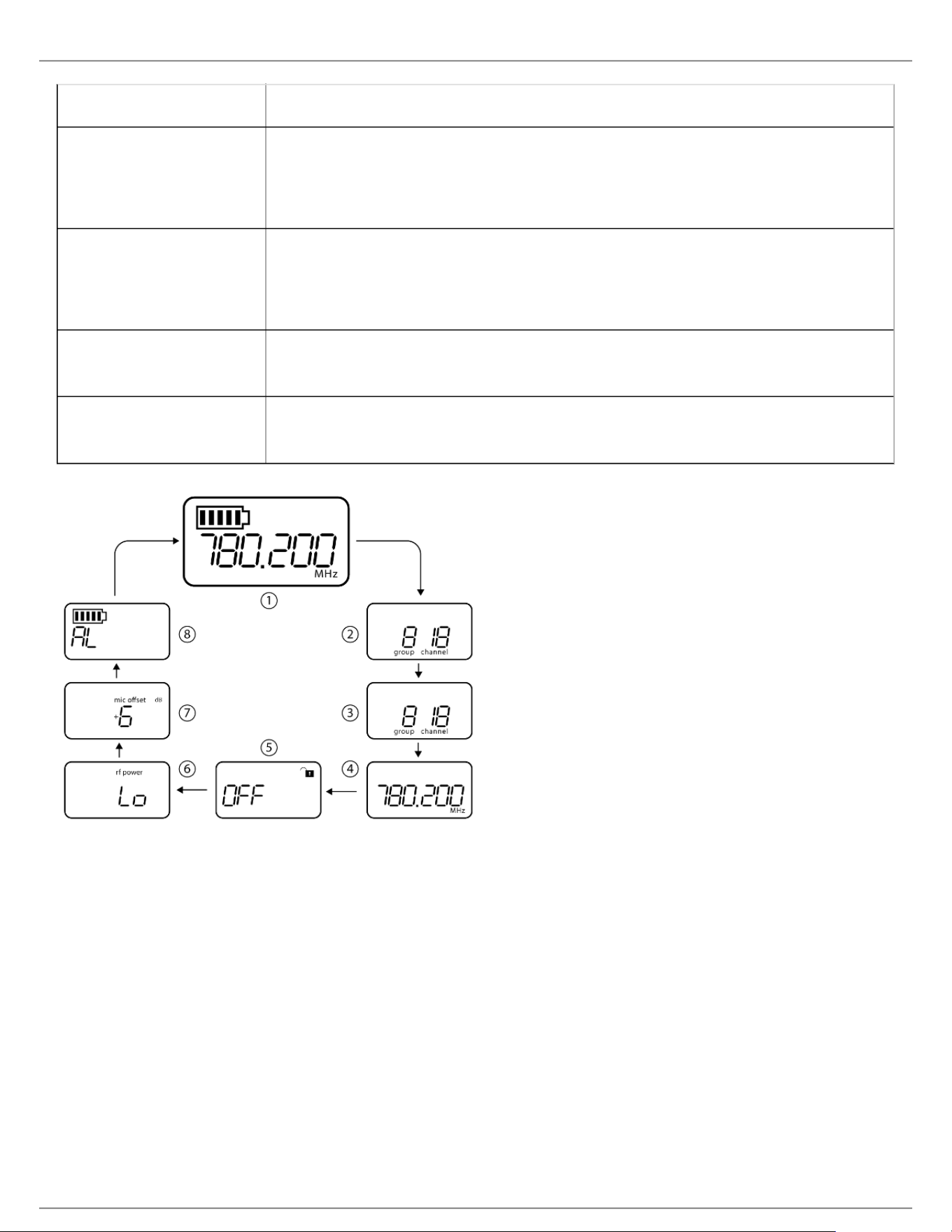
Transmitter Display
① Battery Indicator Bars displayed indicate remaining battery life.
② Home Screen Display:
Group and Channel/
Frequency/SB900 Battery
Runtime
Use the arrow keys to select one of the following home screen displays:
Group and Channel SB900 battery runtime Frequency
③ Encryption Status Icon displayed when encryption is enabled.
④ Lock Displayed when transmitter controls are locked.
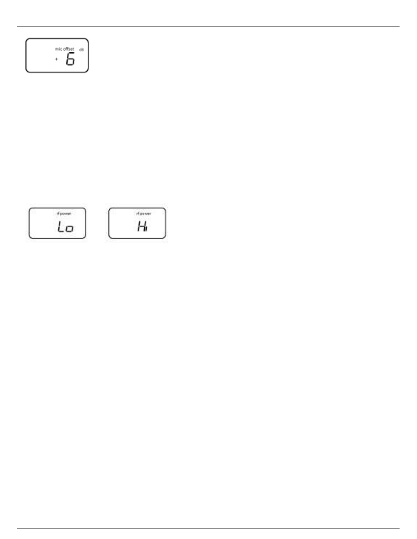
⑤ RF Power RF power setting (Lo or Hi).
⑥ Mic Offset Displays mic offset level in 3 dB increments.
Shure Incorporated
17/60
•
•
•
•
•
•
Transmitter controls
To increase, decrease or change a parameter, use the ▼▲ buttons
To save a menu change, press enter
To exit a menu without saving a change, press the menu button
Bodypack
Handheld
Transmitter Menu Options and Navigation
The transmitter features individual menu screens for setting up and adjusting the transmitter. To access the menu
options from the home screen, press the menu button. Each additional press of the menu button advances to the
next menu screen.
① Home Screen Use the arrow keys to select one of the following home screen displays:
Battery Icon/group and channel
Battery Icon/frequency
Battery Icon/Battery Runtime (SB900 installed)
② group Use the arrow buttons to scroll through the groups.
③ channel Use the arrow buttons to scroll through the channels.
Shure Incorporated
18/60
•
•
•
•
•
•
•
•
•
④ frequency Use the arrow buttons to adjust the frequency. Press and hold for faster scrolling.
⑤ lock Select a lock option:
On = controls locked
OFF = controls unlocked
⑥ rf power Select an rf power setting:
Lo = 1 mW
Hi = 10 mW
⑦ mic offset dB Use to match audio levels between two transmitters used in a combo system.
Range is 0 to 21 dB (3 dB increments). Adjustments occur in realtime.
⑧ battery type Use to set the battery type to match the installed AA battery type to ensure accurate
battery metering. Menu is not displayed when Shure SB900 batteries are installed.
Tips for Editing Menu Parameters
To access the menu options from the home screen, press the menu button. Each additional press of the
menu button advances to the next menu screen.
A menu parameter will blink when editing is enabled
To increase, decrease or change a parameter, use the arrow buttons
To save a menu change, press enter
To exit a menu without saving a change, press menu
Control Lock Options for the Receiver and Transmitter
Control lock options are available for both the receiver and the transmitter to protect against accidental or
unauthorized changes. Locks can be directly set from the component menu, or remotely set from WWB6. To
maintain protection, controls remain locked when the transmitter is turned off and turned on.
Shure Incorporated
19/60
•
•
•
1.
2.
3.
1.
2.
3.
1.
2.
3.
1.
2.
Locking and Unlocking the Receiver Controls
The receiver has the following control lock options which can be used separately or in any combination:
gain: locks the arrow buttons to prevent changes to the audio gain settings
menu: prevents access to menu items and IR sync (gain controls and power switch remain active)
power: disables power switch (gain and menu controls remain active)
To lock a receiver control:
Press the menu button to navigate to the lock settings.
Use the arrow buttons to add or remove the lock options shown next to the lock icon.
Press enter to save the lock settings.
To unlock a receiver:
Tip: To unlock the menu and clear all locks, press and hold the menu button while in the home screen until the
unlock icon appears. Press enter to confirm and save change.
To unlock gain or power settings, navigate to the lock settings by pressing the menu button.
Press the arrow buttons to de-select a lock option.
Press enter to confirm and save change.
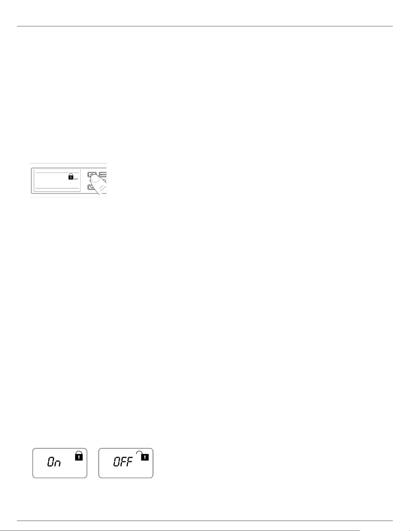
Locking and Unlocking Transmitter Controls
The transmitter controls can be locked or unlocked by selecting On (locked) or OFF (unlocked) from the transmitter
lock menu.
If an attempt is made to access a locked control, the lock icon will flash, indicating that the transmitter controls are
locked.
To set a transmitter lock:
Press the menu button to navigate to the lock settings.
Use the arrow buttons to select on.
Press enter to save. The lock icon appears on the display to confirm that the control locks are enabled.
To unlock the transmitter:
Press and hold the menu button until OFF and the unlock icon appear on the display.
Press enter to save changes.
Shure Incorporated
20/60
•
•
1.
2.
◦
◦
◦
3.
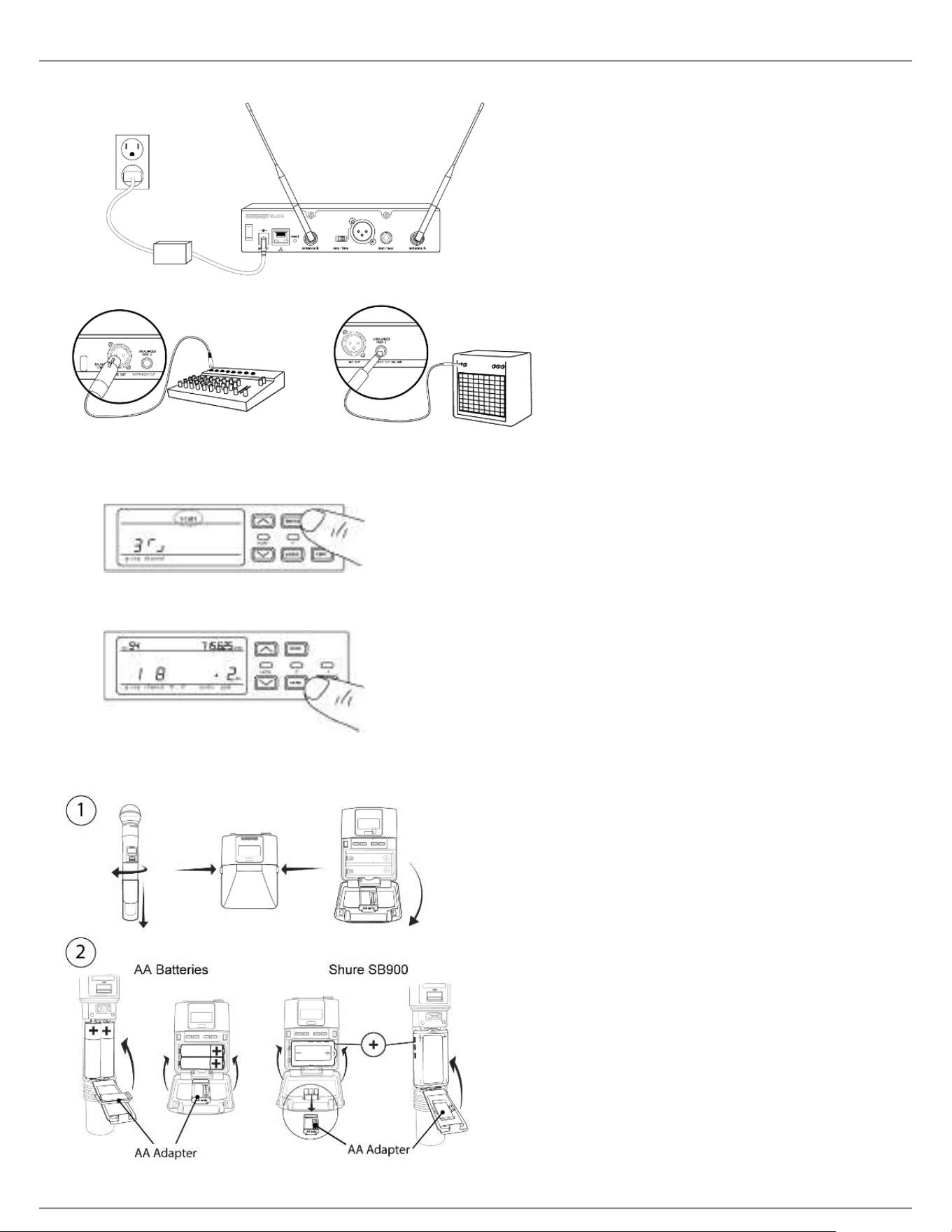
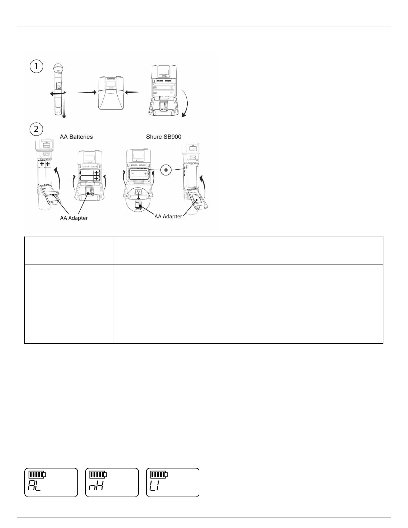
Battery Installation
① Accessing the Battery
Compartment
Press the side tabs on the bodypack or unscrew the cover on the handheld as
shown to access the battery compartment.
② Installing Batteries AA Batteries: Place batteries (note polarity markings) and AA Adaptor as
shown
Shure SB900 Battery: Place battery as shown (note polarity markings),
remove AA Adaptor from bodypack transmitter, stow AA Adaptor in door for
handheld transmitter
Note: If using AA batteries, set the battery type using the transmitter menu.
Setting the AA Battery Type
To ensure accurate display of transmitter runtime, set the battery type in the transmitter menu to match the installed
AA battery type. If a Shure SB900 rechargeable battery is installed, selecting a battery type is not necessary and the
battery type menu will not be displayed.
Press the menu button to navigate to the battery icon.
Use the ▼▲ buttons to select the installed battery type:
AL = Alkaline
nH = Nickel Metal Hydride
Li = Lithium Primary
Press enter to save.
Shure Incorporated
21/60
1.
2.
3.
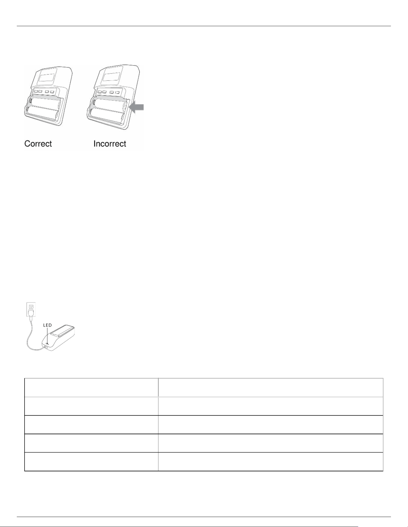
AA Battery Installation
Fully insert the batteries as shown to ensure proper battery contact and to allow the door to latch securely.
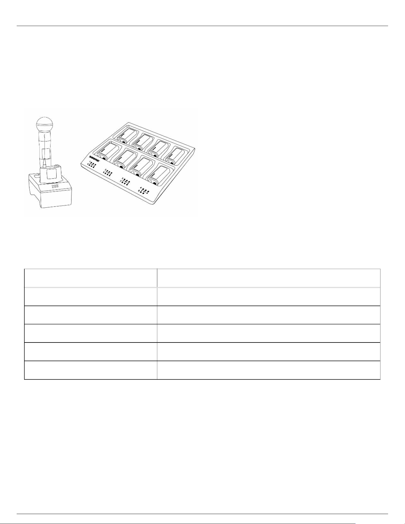
Shure SB900 Rechargeable Battery
Shure SB900 lithium-ion batteries offer a rechargeable option for powering the QLX-D transmitters. Batteries quickly
charge to 50% capacity in one hour and reach full charge within three hours.
Single chargers and multiple bay chargers are available to recharge the Shure batteries.
Caution: Only charge Shure rechargeable batteries with a Shure battery charger.
Single Bay Charger
The single bay charger offers a compact charging solution.
Plug the charger into an AC power source or USB port.
Insert a battery into the charging bay.
Monitor the charging status LEDs until charging is complete.
Charging Status LED
Color Status
Red Charging
Green Charging Complete
Amber Flashing Fault: check connections and battery
Off No battery in bay
Shure Incorporated
22/60
•
•
1.
2.
3.
•
•
•
Multiple Bay Chargers
Shure offers two models of multiple bay chargers:
SBC-200 two bay charger
SBC-800 eight bay charger
Multiple bay chargers can charge individual batteries or batteries installed in transmitters.
Plug the charger into an AC power source.
Insert batteries or transmitters into the charging bay.
Monitor the charging status LEDs until charging is complete.
Charging Status LED
Color Status
Green Charging Complete
Green/Red Charge level above 90%
Red Charging
Amber Flashing Fault: check connections and battery
Off No battery in bay
Important Tips for Care and Storage of Shure Rechargeable Batteries
Proper care and storage of Shure batteries results in reliable performance and ensures a long lifetime.
Always store batteries and transmitters at room temperature
Ideally, batteries should be charged to approximately 40% of capacity for long-term storage
During storage, check batteries every 6 months and recharge to 40% of capacity as needed
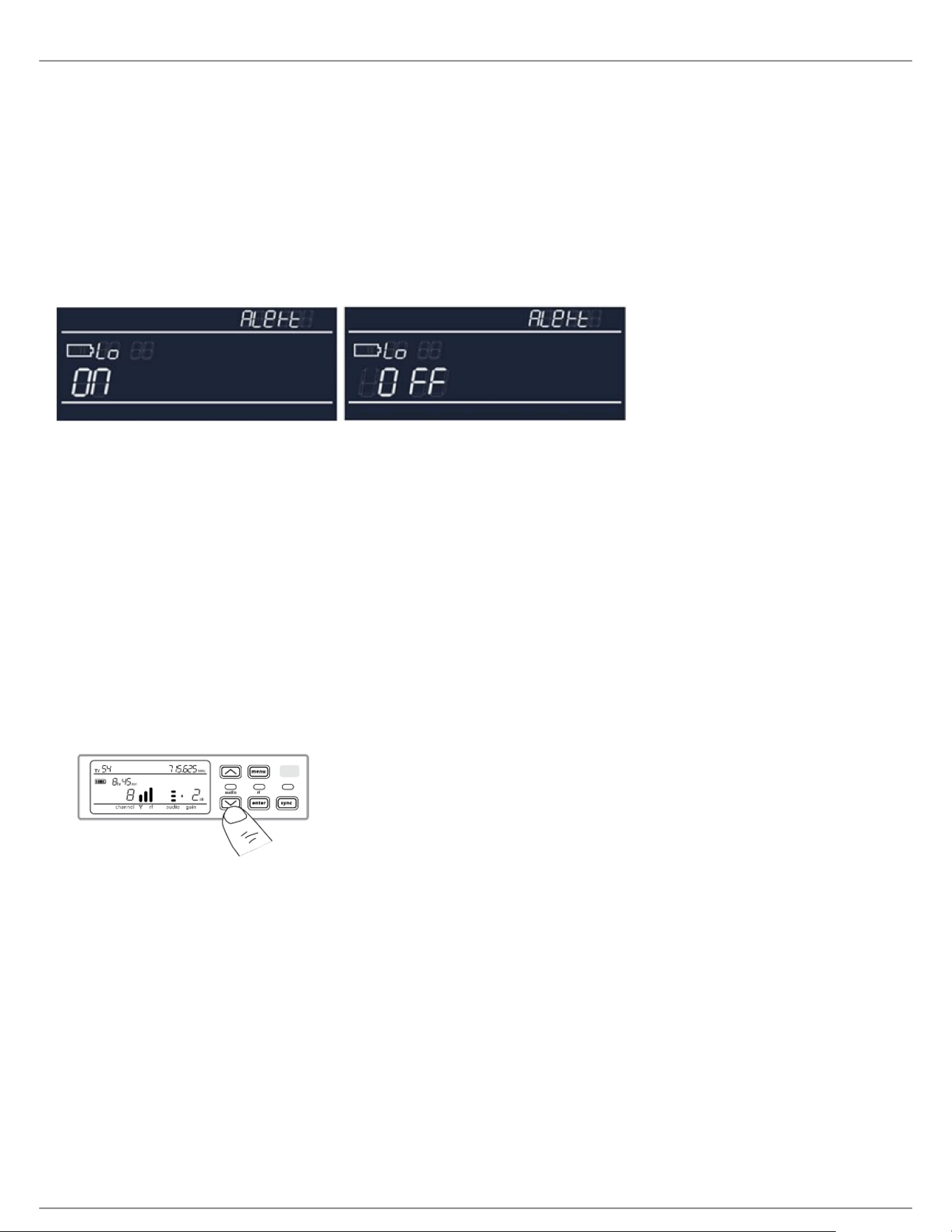
Low Battery Alert
The receiver display can be configured to flash when the battery runtime for a transmitter is less than 30 minutes.
Shure Incorporated
23/60
•
•
1.
2.
3.
4.
•
•
1.
2.
◦
◦
The alert displays the following information based on the type of batteries installed in the transmitter:
SB900 Battery: The receiver screen flashes, the low battery icon is displayed, and the remaining battery
runtime is shown
AA Batteries: The receiver screen flashes and the low battery icon is displayed
Press menu while holding the enter button to access the advanced menu.
Use the arrow buttons to navigate to the Alert screen.
Select On or Off to enable or disable the alert function.
Press the enter button to save.
Receiver Gain Adjustment
The gain control sets the overall signal level for the system. The default gain level is 12 dB and the available gain
range is -18 to 42 dB, in 1 dB increments.
Set the gain to a level where the audio LED appears green or yellow, with only the highest audio peaks causing the
LED to occasionally turn red and engage the limiter. Reduce the gain if there is audible distortion of the audio.
From the receiver home screen, use the arrow buttons to increase or decrease the gain:
A single button press adjusts the gain in 1 dB increments
Press and hold the button for larger adjustments
Test the transmitter at performance levels when adjusting the gain. Monitor the audio meter and the audio LED to
prevent overloads.
Audio Signal Encryption
The QLX-D receiver features Advanced Encryption Standard (AES-256) to protect the audio signal. When
encryption is enabled, the receiver generates a unique encryption key which is shared with a the transmitter during
an IR sync. Transmitters and receivers that share an encryption key form a protected audio path, preventing
unauthorized access by other receivers. To maintain security, components remain encrypted when turned off and
on.
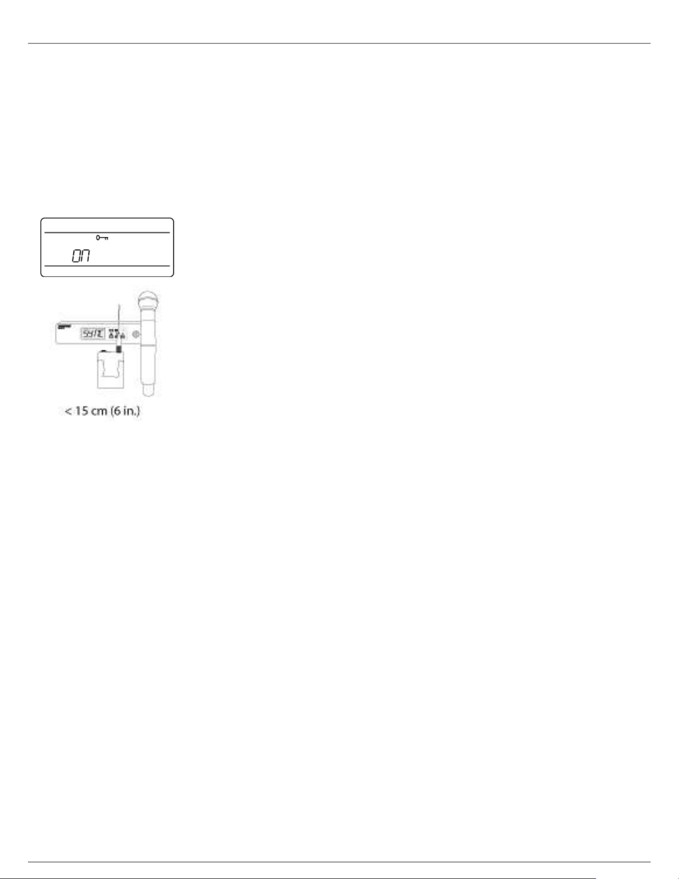
Creating an Encrypted Audio Channel
Press the menu button to navigate to the encryption menu, indicated by the key icon.
Use the arrow buttons to select an encryption option:
on = encryption enabled
OFF = encryption disabled
Shure Incorporated
24/60
3.
4.
1.
2.
3.
4.
•
•
•
Press enter to save. The key icon will be shown on the receiver display.
Press the sync button and align the IR sync windows of the transmitter and receiver. The encryption key icon
will appear on the transmitter screen when the IR sync is complete and the encryption key has been
transferred from the receiver.
Additional transmitters can share the same encryption key with a single receiver. Perform an IR sync to encrypt
each additional transmitter.
Note: When OFF is selected to disable encryption, perform an IR sync to clear the encryption key from the
transmitter and prevent an encryption mismatch error or FAIL message.
Removing Encryption
Press the menu button to navigate to the encryption menu.
Select OFF.
Press enter to save.
IR sync the transmitter and receiver to clear the encryption key from the transmitter and prevent an
encryption key mismatch between components, indicated by a FAIL message.
Note: If encryption has been set from off to on, the receiver will generate a new encryption key and must be IR
synced to the transmitter to share the new key.
System Set Up
Creating Audio Channels
A wireless audio channel is formed when a receiver and transmitter are tuned to the same frequency. To ease setup,
frequencies available to the QLX-D system are organized into groups and channels. Each group contains a number
of channels, and each channel is assigned to a specific preset frequency.
The QLX-D system provides 3 methods for tuning the receiver and transmitter to the same frequency:
Scan and IR Sync: The receiver scans the RF spectrum for the best available frequency and an IR sync
automatically tunes the transmitter to the receiver frequency
Manual Group and Channel Assignment: Manually setting the receiver and transmitter to the same group
and channel number forms an audio channel
Manual Frequency Assignment: Manually setting the receiver and transmitter to the same frequency rather
than using groups and channels forms an audio channel

Shure Incorporated
25/60
•
•
1.
2.
3.
1.
2.
3.
4.
5.
6.
7.
1.
2.
3.
4.
Important: Before you begin a scan or frequency assignment:
Turn off: All transmitters for system you are setting up to prevent interference with frequency scans.
Turn on: The following potential sources of interference including other wireless systems, computers, CD
players, large LED panels, and effects processors to prevent selection of occupied frequencies.
Scan and IR Sync
The simplest way to create an audio channel is to use the scan function to find the best available receiver channel,
and then use the IR sync feature to automatically tune the transmitter to the receiver channel.
Step 1: Scanning to Find the Best Channel
The Scan function automatically selects the best available receiver channel.
Navigate to the Scan menu option.
Press enter to start the scan.
When the scan is complete, the channel will appear on the display.
Network Scan
The Network Scan feature automates frequency assignment by using a single receiver to scan and deploy
frequencies to all networked receiver within the same frequency band.
Network Scanning and Frequency Deployment
Connect receivers to an active Ethernet network. All receivers must be on the same subnet.
Prior to performing a network scan, turn on all receivers and allow 60 seconds for all receivers to join the
network.
Choose a group or custom group for deployment on the receiver that will be used to initiate the network scan.
To start a network scan, press the menu button and navigate to the network scan menu. Press enter.
When the scan is complete, the displays of receivers waiting for frequencies will flash.
Press enter to deploy the frequencies or press menu to cancel the deployment.
The front panel LEDs on each receiver will blink when a deployed frequency has been assigned.
Note: Full frequency deployment may not occur if the number of receivers in the network exceeds the number of
available frequencies in the selected group. Try another group or rescan after turning off unused receivers.
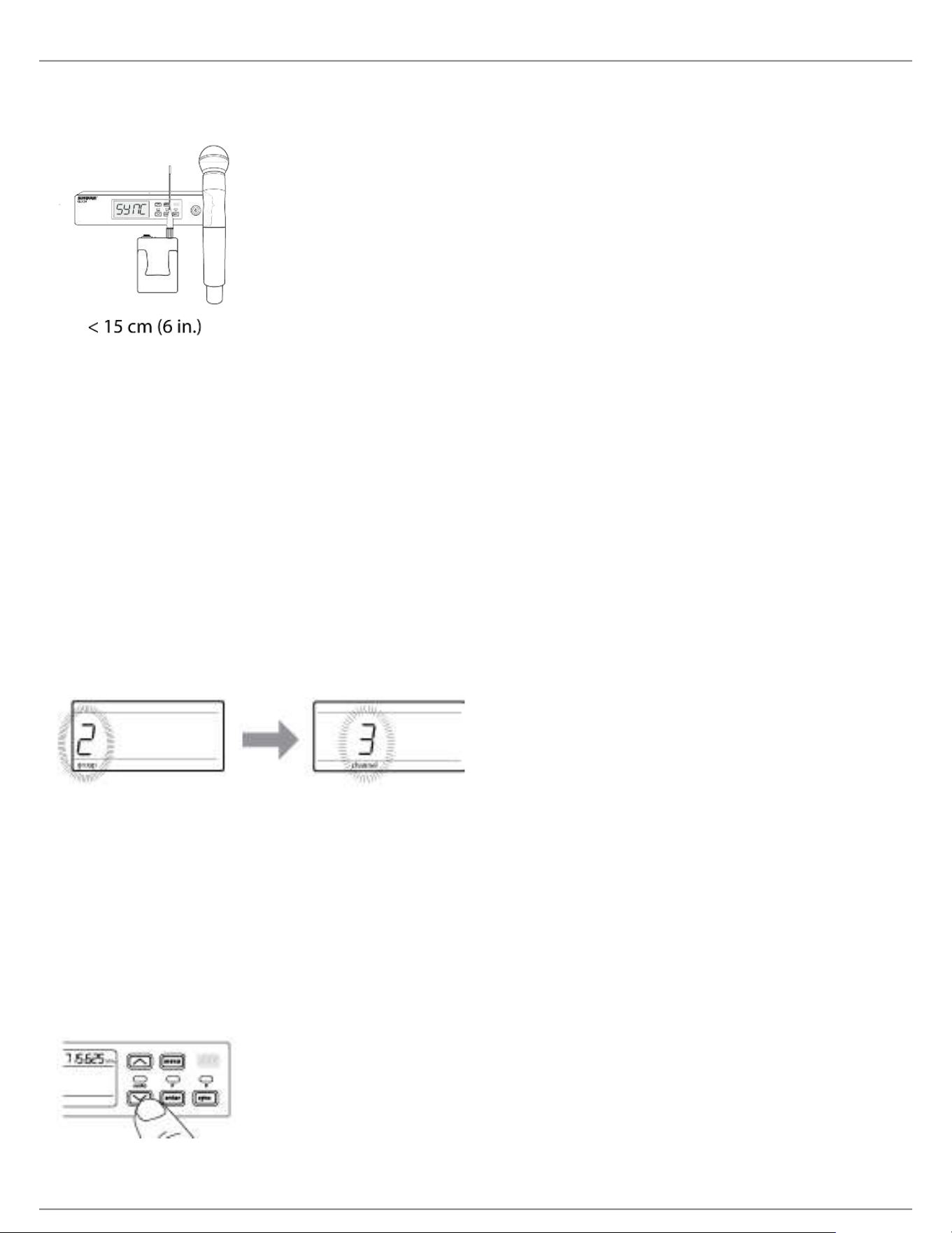
Step 2: IR Sync for Automatic Transmitter Set Up
Performing an IR Sync automatically tunes the transmitter to match the receiver frequency, forming a wireless audio
channel.
Turn on the transmitter.
Press the sync button on the receiver. The red ir LED will blink indicating that sync mode is active.
Align the IR sync windows of the transmitter and receiver at a distance of <15 cm (6 in.). When the transmitter
and receiver are aligned, the red ir LED remains on and the sync will automatically occur.
sync good appears on the display when IR sync is complete. The blue rf LED will illuminate indicating that the
transmitter is within range of the receiver.
Shure Incorporated
26/60
1.
2.
3.
4.
5.
1.
2.
3.
Note: If the IR sync fails, repeat the IR sync procedure, carefully maintaining alignment between the IR
windows of the transmitter and receiver.
Manual Group and Channel Assignment
An audio channel can be manually created by simply setting the receiver and transmitter to the same group number
and channel number. For example, a receiver set to Group 2, Channel 3 and a transmitter set to Group 2, Channel 3
would form an audio channel.
Use manual group and channel configuration to assign specific groups and channels to receivers and transmitters
as an alternative method to automatically creating channels with IR sync.
Use the following steps to set the group and channel in the receiver and transmitter:
Navigate to the group setting.
Use the arrow buttons to scroll through the groups.
Press enter to select a group.
Next, use the arrow buttons to select a channel.
Press enter to save.
Manual Frequency Selection
Manual frequency selection can be used instead of groups and channels to set the transmitter and receiver to a
specific frequency. For example, an audio channel can be created by setting the receiver and transmitter to same
frequency.
Setting the Receiver Frequency
Press menu to navigate to the frequency setting option.
Use the arrow buttons to adjust the frequency. Press and hold for faster scrolling.
Press enter to save.
Shure Incorporated
27/60
1.
2.
3.
1.
2.
3.
4.
1.
2.
3.
Setting the Transmitter Frequency
Press menu to navigate to the frequency setting option.
Use the arrow buttons to adjust the frequency. Press and hold for faster scrolling.
Press enter to save.
Linking Two Transmitters to a Receiver
Linking two transmitters to a receiver offers the flexibility to provide a performer with either a handheld or bodypack
transmitter to meet their preference. For performances requiring instrument changes, two bodypack transmitters can
be linked to a single receiver.
Note: Only turn on and operate one transmitter at a time to prevent interference between the transmitters.
Syncing the Transmitters to the Receiver
Both transmitters must be individually linked to the receiver by performing an IR Sync.
Turn on the first transmitter and perform an IR Sync with the receiver.
Perform a sound check and adjust the transmitter gain if necessary. When finished, turn off the transmitter.
Turn on the second transmitter and perform an IR Sync with the receiver.
Test the transmitter at performance conditions and adjust the transmitter gain if necessary. When finished,
turn off the transmitter.
Matching Audio Levels with Mic Offset
When linking two transmitters to a receiver, there may be a difference in volume levels between microphones or
instruments. If this occurs, use the Mic Offset function to match the audio levels and eliminate audible volume
differences between transmitters. If using a single transmitter, set Mic Offset to 0 dB.
Turn on the first transmitter and perform a sound check to test the audio level. Turn off the transmitter when
finished.
Turn on the second transmitter and perform a sound check to test the audio level.
If there is an audible difference in the sound level between the transmitters, navigate to the Mic Offset menu
on the transmitter to increase or decrease the Mic Offset in realtime to match the audio levels.
Shure Incorporated
28/60
•
•
1.
2.
3.
•
•
•
1.
2.
3.
4.
Radio Frequency (RF) Settings
Setting the Transmitter RF Power
The transmitter offers two RF power settings which determine the transmitter range.
Lo = 1 mW
Hi = 10 mW
Use the Lo setting when the transmitter and receiver are in close proximity.
Navigate to the transmitter rf power menu.
Use the arrow buttons to select Hi or Lo.
Press enter to save.
Shure AXT600 Spectrum Manager Compatibility
QLX-D receivers are compatible with the Axient AXT600 Spectrum Manager. Networked receivers will appear in the
device inventory and frequencies from the Compatible Frequency List can be deployed and monitored by the
Spectrum Manager. For more information regarding the Spectrum Manager, see the Axient System Guide.
Using QLX-D with a Shure ULX-D System
Transmitters and receivers from QLX-D and ULX-D component groups can be paired to form audio channels.
To ensure functionality, use the following settings on receivers and transmitters:
Encryption set to Off
High Density Mode set to Off (ULX-D receiver)
Manually tune the receiver and transmitter to the same frequency. IR sync between QLX-D and ULX-D
components is not supported.
To create an audio channel, manually set the receiver frequency to match the frequency of the transmitter.
If using ULXD6 or ULXD8 transmitters with a QLX-D receiver, you can only make changes to transmitter presets
using Wireless Workbench.
Open receiver properties in WWB.
Make changes to transmitter presets and click Apply. The new settings will be sent to the QLX-D receiver.
On the receiver front panel, hold enter while pressing menu to enter the advanced menu.
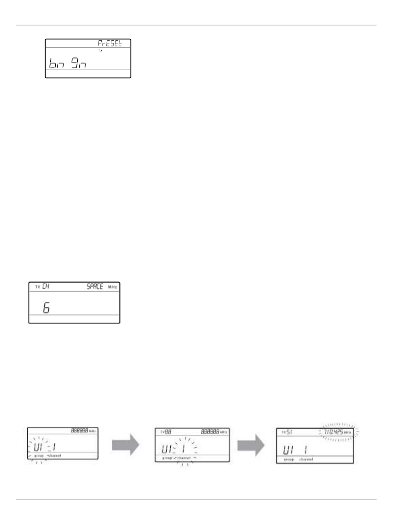
Press menu to advance to Preset bn gn. The IR window will flash.
Shure Incorporated
29/60
5.
•
•
•
•
•
1.
2.
3.
4.
Align the transmitter IR window with the receiver to send the presets to the transmitter.
Important: All QLX-D and ULX-D components must use 2.0 firmware or greater for proper functionality.
Setting Regional TV Channel Spacing
The parameter for TV channel spacing allows the receiver to match regional TV bandwidth usage and accurately
display local TV channels.
The following channel bandwidth options are available:
6 MHz
7 MHz
8 MHz
6 JP (Japan)
off (use to turn off TV channel display)
To set the TV channel spacing:
Press and hold the enter button, and then press the menu button to access the advanced features menu.
Press the menu button to navigate to the TVCH menu.
Use the arrow buttons to select the channel bandwidth that corresponds to the local region.
Press enter to save.
Custom Groups
Specific channels and frequencies can be selected and placed into custom groups. Custom groups are commonly
used to assign networked receivers to a specific range of frequencies or to pre-configure receivers for rental
applications. Once a custom group has been created, it can be loaded to the receiver using the group menu.
When network scan is used to assign frequencies from a receiver with a custom group selected, all of custom
groups (U1, U2, U3, etc...) from that receiver will be loaded to all other receivers on the network.
Creating Custom Groups

Shure Incorporated
30/60
1.
2.
3.
4.
1.
2.
1.
2.
1.
2.
3.
4.
1.
2.
3.
4.
1.
2.
3.
Selecting A Custom
Group
The receiver has 6 custom groups available named U1, U2, U3, U4, U5, and U6.
Press menu while holding the enter button to access the Custom Group
screen.
Press enter to enable editing of a group (indicated by the group flashing).
User the arrow buttons to select a group (U1 to U6).
Press enter to advance to channel selection.
Selecting a Channel Use the arrow buttons to select a channel (1-60). Each group can contain up
to 60 channels (frequencies).
Press enter to save the selected channel and advance to frequency
assignment.
Assigning a Frequency to
a Channel
Use the arrow buttons to assign a frequency to the selected channel.
Press enter to save.
After pressing enter, the channel will flash to allow for adding more channels and
frequencies to the custom group. To add more channels and frequencies, repeat
steps 2 and 3. When finished, press the menu button several times to return to the
main menu.
Transmitter IR Sync from a Custom Group
To ensure accurate display of group and channel information, IR sync the transmitter from the Custom Group menu
screen:
Press menu while holding the enter button to access the Custom Group screen.
Turn on the transmitter and press the sync button on the receiver.
Align the IR sync windows of the transmitter and receiver.
sync good appears on the display when IR sync is complete.
Note: If the IR sync fails, repeat the IR sync procedure, carefully maintaining alignment between the IR windows of
the transmitter and receiver.
Deleting a Custom Group
Press menu while holding the enter button to access the Custom Group screen.
Press enter to enable editing of a group (indicated by the group flashing).
User the arrow buttons to navigate to display the group number and the words DEL.
Press enter to delete the group.
To delete individual channels from a custom group, do the following:
Enter the custom groups menu and select the frequency for the channel to be deleted.
Press and hold an arrow button until the frequency displays ---.--- MHz.
Press and hold the menu button to confirm change and exit.
Creating Custom Groups using Wireless Work Bench 6
Custom groups can be created in WWB6 by accessing the Frequency Coordination tab. Refer to the WWB6 help
system for detailed instructions for configuring Custom Groups.

Shure Incorporated
31/60
1.
2.
3.
1.
2.
•
•
•
•
•
•
•
•
•
1.
2.
3.
4.
5.
Networking
The receiver uses an Ethernet connection to network with other components and includes an internal DHCP client
for automatic network configuration when connected to a DHCP enabled router.
Connecting to a Network
Insert an Ethernet cable in the Ethernet port on the rear of the receiver.
Connect the cable to a computer or router.
The port LEDs on the receiver will illuminate to indicate network connectivity and network traffic.
Automatic IP Addressing
Enable a DHCP service on the server or use a DHCP enabled router.
When the receiver is powered on, the DHCP server will automatically assign an IP address to the receiver.
Tip: Use the network reset option available in the advanced features menu to return the receiver to the default
DHCP addressing mode.
Configuration Tips
Use shielded Cat 5 or better Ethernet cables to ensure reliable network performance
The LEDs on the Ethernet port illuminate indicating a network connection is active
The network icon illuminates when the receiver detects additional Shure devices on the network
All components must operate on the same subnet
Use multiple Ethernet switches to extend the network for larger installations
Network Troubleshooting
Use only one DHCP server per network
All devices must share the same subnet mask
All receivers must have the same level of firmware revision installed
Look for the illuminated network icon on the front panel of each device:
If the icon is not illuminated, check the cable connection and the LEDs on the Ethernet port.
If the Ethernet port LEDs are not illuminated and the cable is plugged in, replace the cable and recheck the
LEDs and network icon.
To check connectivity of WWB6 to the network:
Start WWB6 software and use Inventory view to see devices connected to the network.
If not, find the IP address from one of the devices on the network (such as a receiver) and see if you can ping
it from the computer running WWB6.
From a WINDOWS/MAC command prompt, type ‘ping IPADDRESS’ of the device (e.g. "ping 192.168.1.100").
If the ping returns success (no packet loss), then the computer can communicate with the device on the
network. If the ping returns failure (100% packet loss), then verify that the IP address of the computer is on
the same subnet as the receiver.
If the pings are successful and the devices still do not show up in the WWB6 inventory, check to ensure all
firewalls are either disabled or allow the WWB network traffic to pass to the application. Check that firewall
settings are not blocking network access.
Setting the IP Address and Subnet Mask Manually
IP addresses and subnet masks can be manually set from the advanced menu in the receiver or from the monitor
panel in Wireless Workbench 6.
Shure Incorporated
32/60
1.
2.
3.
4.
5.
6.
7.
1.
2.
3.
4.
•
•
Network settings entered manually must be valid and conform to IP protocols to ensure proper network
communication.
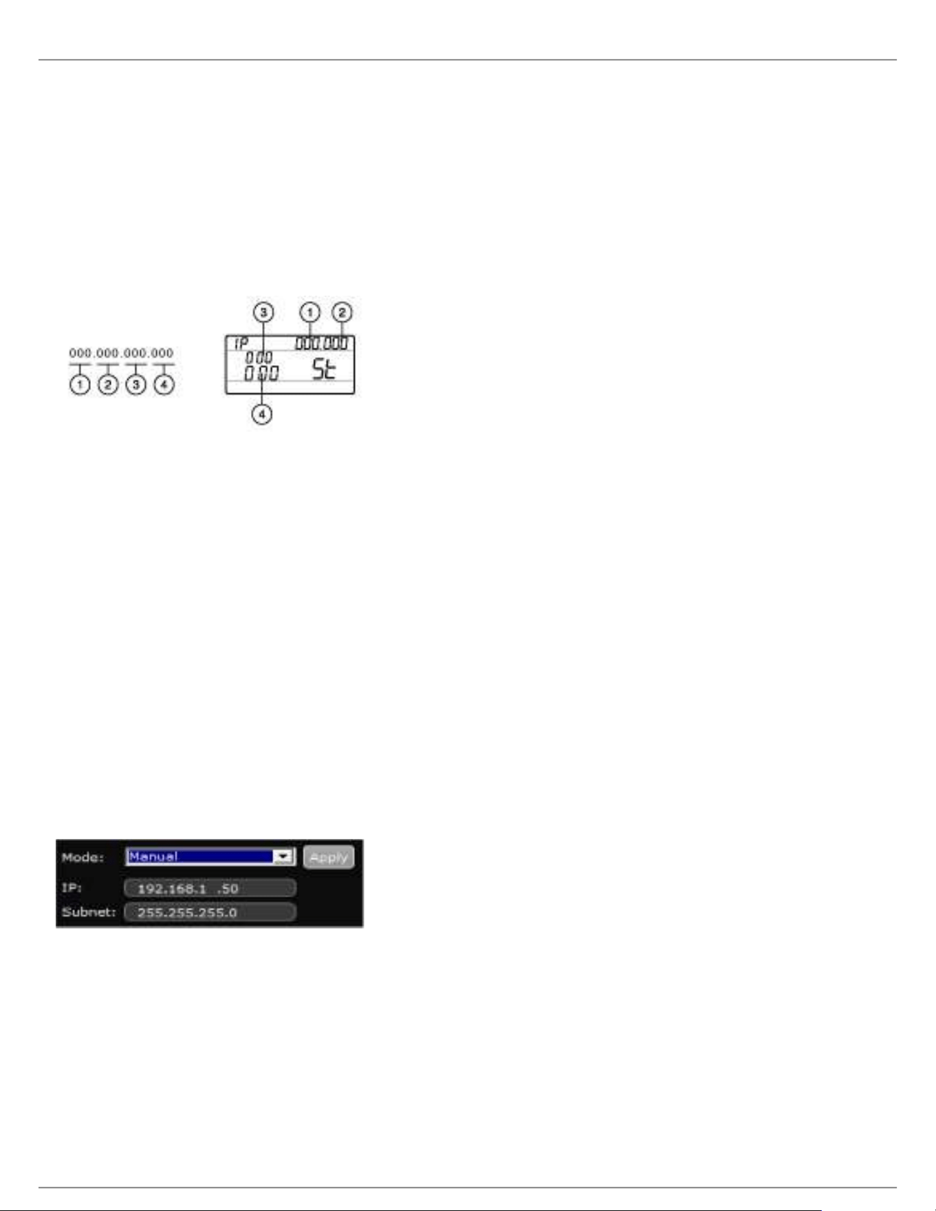
Receiver Menu
IP addresses and subnet addresses contain 4 groups of numbers. Each group can contain up to 3 digits. A decimal
point separates each group.
When setting an IP address or subnet address, each of the 4 groups must be edited individually. The following
diagram shows how the groups are mapped to the receiver display:
Press menu while holding the enter button to access the advanced menu.
Press the menu button to navigate to the IP menu.
Use the arrow buttons to set the mode to St (static) and press enter.
Use the arrow buttons to edit the first group. Press enter to save and continue to the next group.
Use the arrow buttons and enter button to edit the remaining 3 groups.
When group 4 has been edited, the display will show the subnet mask menu. Use the arrow buttons to scroll
and select a preset value for each of the subnet mask groups.
When finished, press enter to save settings.
Note: To restore automatic DHCP IP addressing, enter the IP menu and select AU (automatic). The Network Reset
menu option can also be used to restore DHCP addressing.
Wireless Workbench 6
Open the Channel Properties tab in WWB6.
Click on Utilities and set the networking mode to Manual.
Enter valid numbers in the IP and Subnet fields.
When finished, select Apply.
Connecting to an External Control System
The receiver connects to external controls systems (AMX or Crestron) via Ethernet cables.
Connection: Ethernet (TCP/IP; QLXD receiver is the client)
Port: 2202
For a comprehensive list of command strings, visit: http://shure.custhelp.com/

Shure Incorporated
33/60
Managing QLX-D with Wireless Workbench 6
Shure's Wireless Workbench 6 (WWB6) software enables networked monitoring and control of the QLX-D receiver.
Additional tools in WWB6 offer RF spectrum monitoring, network configuration, and firmware updating.
Visit www.shure.com/wwb for a free download of Wireless Workbench software.
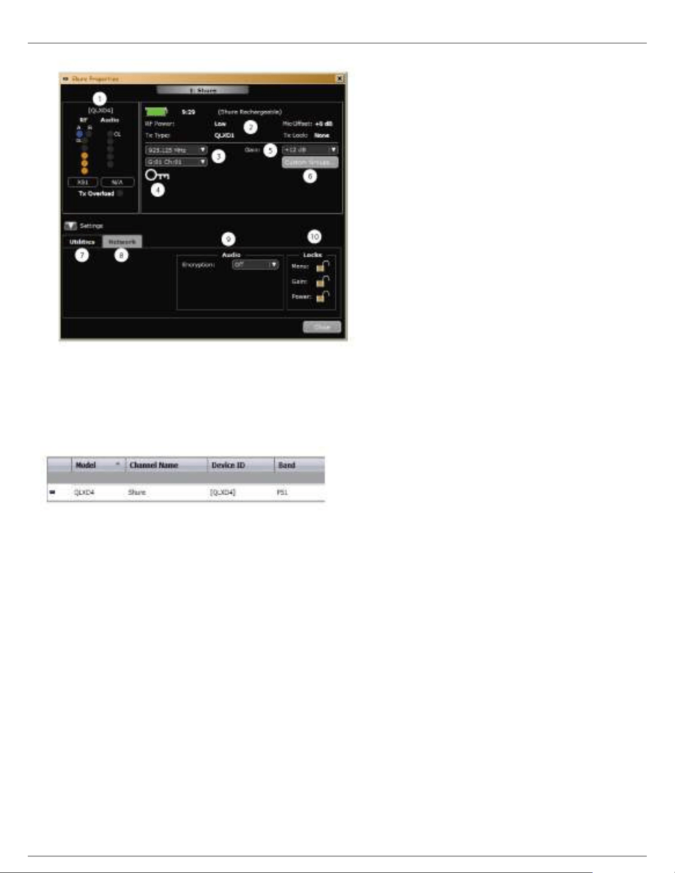
Managing and Monitoring Settings
Manage and monitor receiver settings by opening the Monitor tab in Wireless Workbench. Click on the Settings
button to show or hide the full Properties window.
① RF and Audio Meters
Displays: current levels, band, TV, and TX Overload
② Transmitter Settings
Displays: RF Power, Tx Type, Mic Offset, Tx Lock
③ Frequency Settings
Use drop-down to edit frequency value
④ Encryption Icon
Illuminates when Encryption is enabled
⑤ Receiver Gain Setting
Use drop-down to increase or decrease gain settings
⑥ Custom Groups
Click to enter to create custom groups
⑦ Utilities
Access receiver functions
⑧ Network Tab
Set network mode, view: IP address, Subnet, MAC, Firmware version, Network reset
⑨ Encryption
Enable/Disable Encryption
⑩ Receiver Locks
Lock/Unlock: Menu, Gain, Power
Shure Incorporated
34/60
Viewing the Receiver in WWB6 Inventory
Click on the Inventory tab to view the receiver channels. Double-click on parameters to enable editing.
Tip: Clicking on the receiver icon next to the channel name flashes the front panel LEDs on the receiver for remote
identification.
Hardware Identify
When Hardware Identify is triggered from a receiver, the corresponding representation of that receiver is flashed in
the WWB inventory display, allowing for remote identification.
Hardware Identify can be triggered from the receiver by pressing and holding the enter button for at least 3 seconds.
Click the Dismiss button on the WWB Inventory screen to exit the function.
Firmware Updates
Firmware is embedded software in each component that controls functionality. Periodically, new versions of firmware
are developed to incorporate additional features and enhancements.
Firmware Versioning
When updating receiver firmware, update transmitters to the same firmware version to ensure consistent operation.
The firmware version is numbered in the form of MAJOR.MINOR.PATCH (e.g., 1.2.14). At a minimum, all devices on
the network (including transmitters), must have the same MAJOR and MINOR firmware version numbers (e.g.,
1.2.x).
Shure Incorporated
35/60
1.
2.
3.
4.
5.
6.
7.
1.
2.
◦
◦
3.
4.
5.
Downloading and Updating Firmware
A free Shure Update Utility tool is available by visiting www.shure.com. The Shure Update Utility is also bundled with
Shure Wireless Workbench software.
Refer to the help instructions to use the Shure Update Utility.
Updating the Receiver
CAUTION! Ensure that receiver power and network connections are maintained during a firmware update. Do not
turn off the receiver until the update is complete.
Connect the receiver and computer to the same network.
Open the Shure Update Utility.
Click on the firmware tab to find available updates.
Use the Import button if manually importing firmware files.
Click the Update Device tab and check the Version to install box next to each device.
Click Send Updates to load the firmware to the networked devices.
When the download is complete, the receiver will reboot with the updated firmware installed.
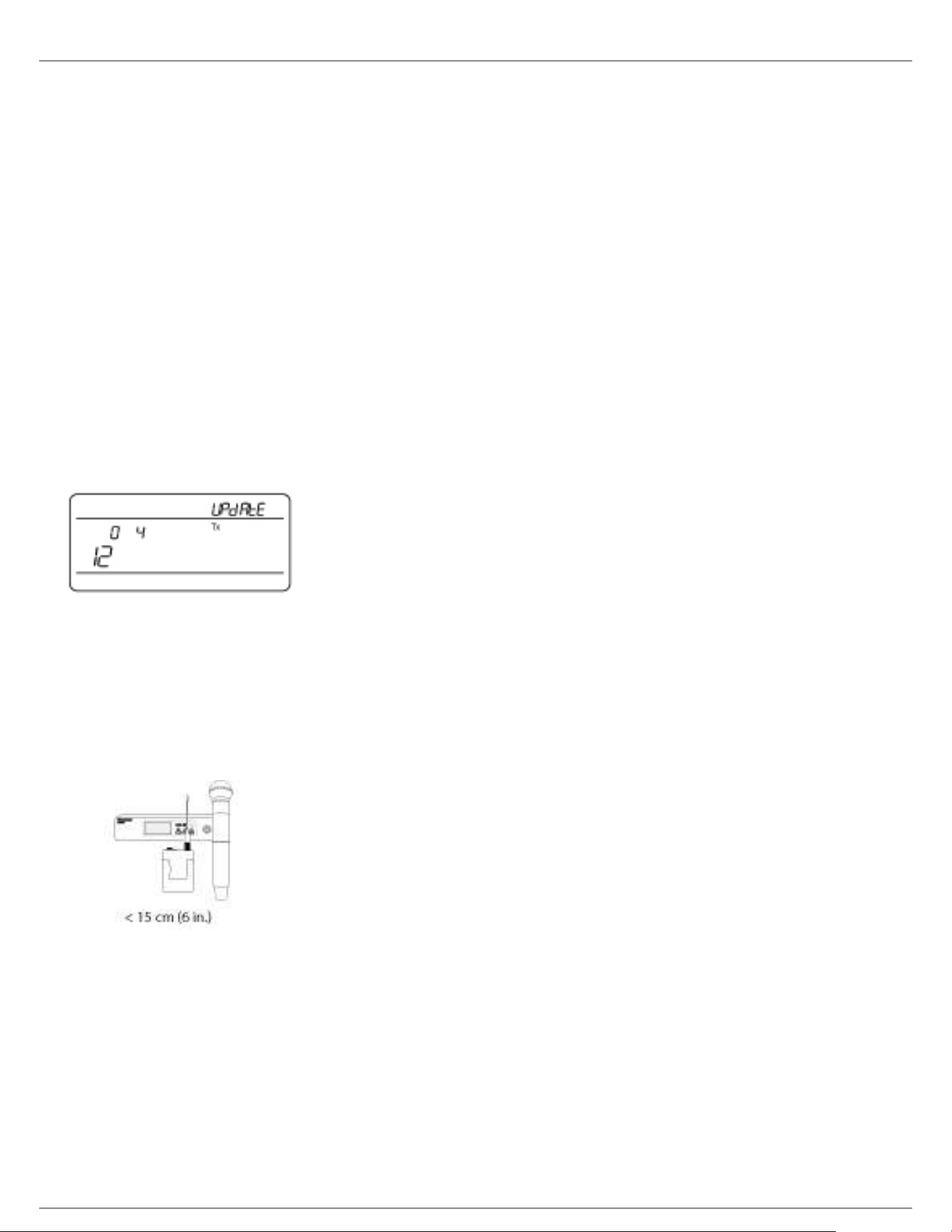
Updating the Transmitter
To update transmitters, download firmware to the receiver. You can download firmware for handheld and bodypack
transmitters, or for boundary and gooseneck transmitters. The receiver sends firmware to the transmitter using the
IR Sync window.
Press menu while holding the enter button to access the advanced menu. Use the menu button to navigate to
the update menu.
The receiver displays the type of transmitter firmware it has available. The receiver holds one type of firmware
at a time.
HH BP = handheld or bodypack firmware
BN GN = gooseneck or boundary firmware
Press enter to start the update.
When the red IR LED flashes, align the receiver and transmitter IR sync ports. The red LED will remain
illuminated to indicate correct alignment and the download will automatically start.
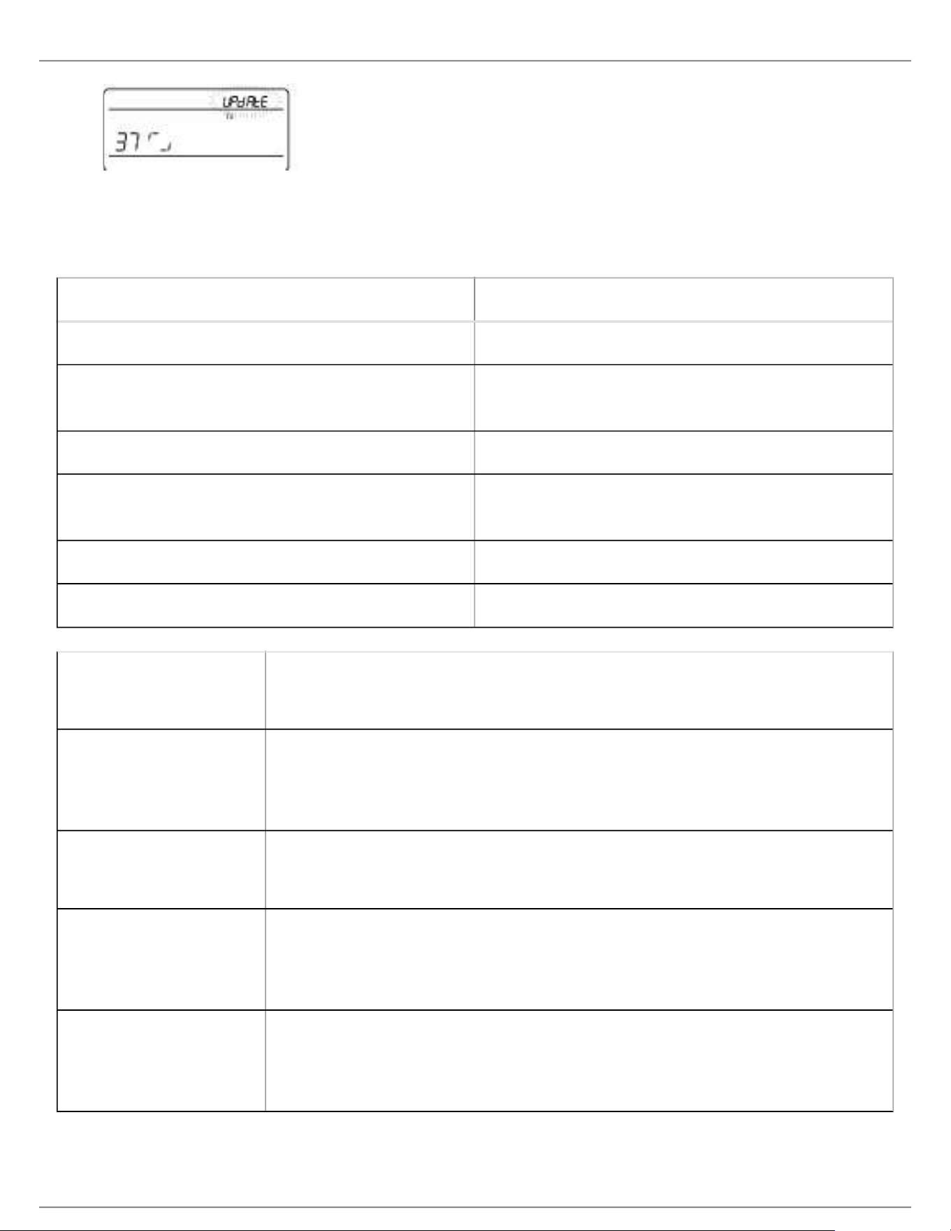
Maintain alignment during the update and monitor download progress (0 to 100%) on the receiver screen.
Shure Incorporated
36/60
6. When the update is complete, "TX Update good" is shown on the receiver display. If the screen shows Err. 09,
update again with a transmitter type that matches the firmware held by the receiver.
Troubleshooting
Issue See Solution...
No Sound Power, Cables, or Radio Frequency
Faint sound or distortion Gain, Cables, Reducing Interference or Radio
Frequency
Lack of range, unwanted noise bursts, or dropouts RF
Cannot turn transmitter off or change frequency
settings, or can't program receiver
Interface Locks
Receiver display shows FAIL after encryption is disable Encryption Mismatch
Group and Channel display shows "--" Custom Group IR Sync
Power Make sure that the receiver and transmitter are receiving sufficient voltage. Check
the battery indicators. Replace or recharge the batteries if necessary.
Gain Adjust the system gain on the front of the receiver. Ensure the mic/line switch
setting (XLR output only) on the back of the receiver corresponds to the input of the
mixing console, amplifier, or processor.
Cables Check that all cables and connectors are fully engaged or locked into position.
Inspect cables for damage. Replace if necessary.
Interface Locks The transmitter and the receiver can be locked to prevent accidental or
unauthorized changes. If a locked control is accessed, the lock icon on the display
will flash. Follow the instructions to unlock the receiver or transmitter.
Firmware Mismatch Paired transmitters and receivers must have the same firmware version installed to
ensure consistent operation. See Firmware Updates topic for firmware update
procedure.

Shure Incorporated
37/60
•
•
•
•
•
•
•
•
•
Encryption Mismatch Indicates an encryption key mismatch has been detected. Perform an IR sync
between the receiver and transmitter to clear the error.
Custom Group IR Sync When using Custom Groups, always perform an IR sync from the Custom Groups
menu in the receiver to ensure accurate display of group and channel information.
See Custom Groups topic for additional details.
Radio Frequency (RF) The blue RF LED will illuminate when a linked transmitter is within range of the
receiver. Measure the transmitter range before a performance to avoid operating
beyond the specified transmitter range.
The RF meter bars indicate amount of RF power being received. This signal could
be from the transmitter, or it could be from an interfering source, such as a
television broadcast. If the meter shows a signal level when the transmitter is off,
then that channel may have interference. Check the surrounding area for sources of
interference or change the receiver to a clear frequency.
A red RF LED indicates RF overload. Avoid operating multiple systems in close
proximity.
Frequency Compatibility Perform a Scan and Sync to ensure the transmitter and receiver are set to the
same channel or frequency
Look at the label on the transmitter and receiver to make sure they are in the
same band (G50, J50, L50, etc...).
Reducing Interference Perform a scan to find the best open frequency. Perform an IR sync to
transfer the settings to the transmitter.
For multiple systems, make sure that each receiver is assigned to a unique
channel. Interference will occur if two transmitters are set to the same
channel.
Maintain a line of sight between transmitter and receiver antennas.
Move receiver antennas away from metal objects or other sources of RF
interference (such as CD players, computers, digital effects, network
switches, network cables and Personal Stereo Monitor (PSM) wireless
systems).
Eliminate RF overload (see below).
Increasing Range Increase transmitter RF power level to Hi
Use an active directional antenna, antenna distribution system, or other
antenna accessory to increase RF range

Shure Incorporated
38/60
•
•
•
•
•
•
Eliminating RF Overload If the RF OL icon appears on the RF meter, try the following:
Reduce the transmitter RF power level from Hi to Lo
Move the transmitter further away from the receiver—at least 6 m (20 ft)
If you are using active antennas, reduce antenna or amplifier gain.
Use omnidirectional antennas
Error Codes and Solutions
Error codes are generated when the receiver detects a condition that can potentially affect system performance.
If an error is displayed on the receiver, use the following table to identify the problem and find the corresponding
solution.
Error
Code Description Solutions
Err.001 Audio Compatibility Update transmitter and receiver firmware to the latest version.
Err.002 Encryption Mismatch between
Shure product lines
Set encryption to off for components from different Shure
products lines, such as QLX-D and ULX-D.
Err.003 Encryption Mode Mismatch Perform an IR sync between the transmitter and receiver to
clear the error.
Err.004 Band Mismatch Receiver and transmitter are operating in overlapping
frequencies from different bands.
Err.005 Frequency Mismatch Receiver and transmitter are from bands that do not share
compatible frequencies.
Err.006 No Frequencies Found Rescan, select a different group, or use WWB to find a
frequency.
Err.007 Firmware Mismatch Update firmware on the transmitter and receiver.
Err.008 Shure SB900 battery runtime does
not appear on display
Check that battery is firmly installed into the battery
compartment. If condition persists, replace the battery.
Err.009 Transmitter Type Mismatch To complete the firmware update, match the type of transmitter
to the type of firmware the receiver currently has.
HH BP = handheld or bodypack firmware
BN GN = gooseneck or boundary firmware
Shure Incorporated
39/60
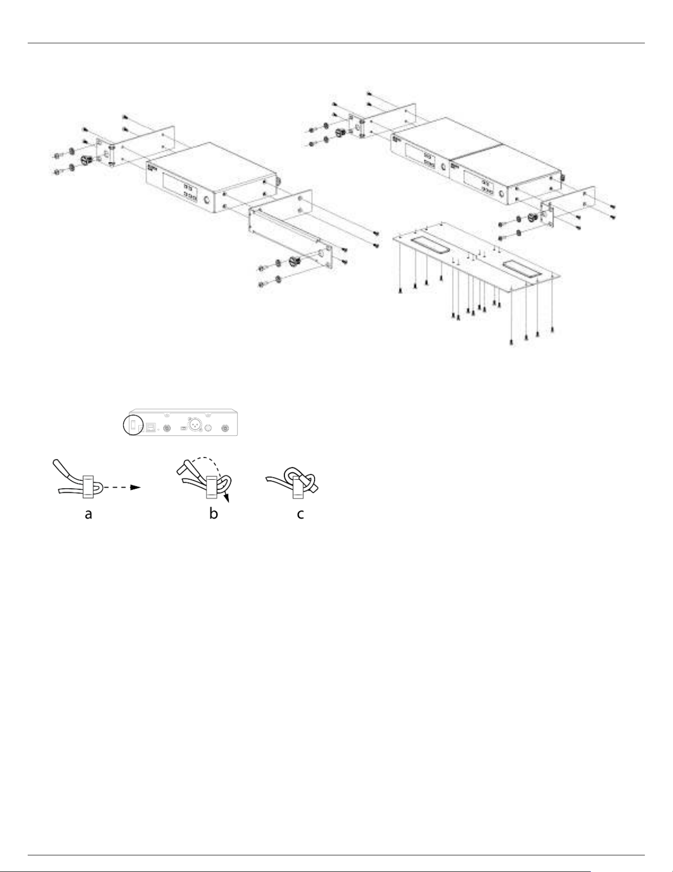
Single and Dual Rackmount Assembly
Securing the AC Power Cord
Shure Incorporated
40/60
Installing Footpads
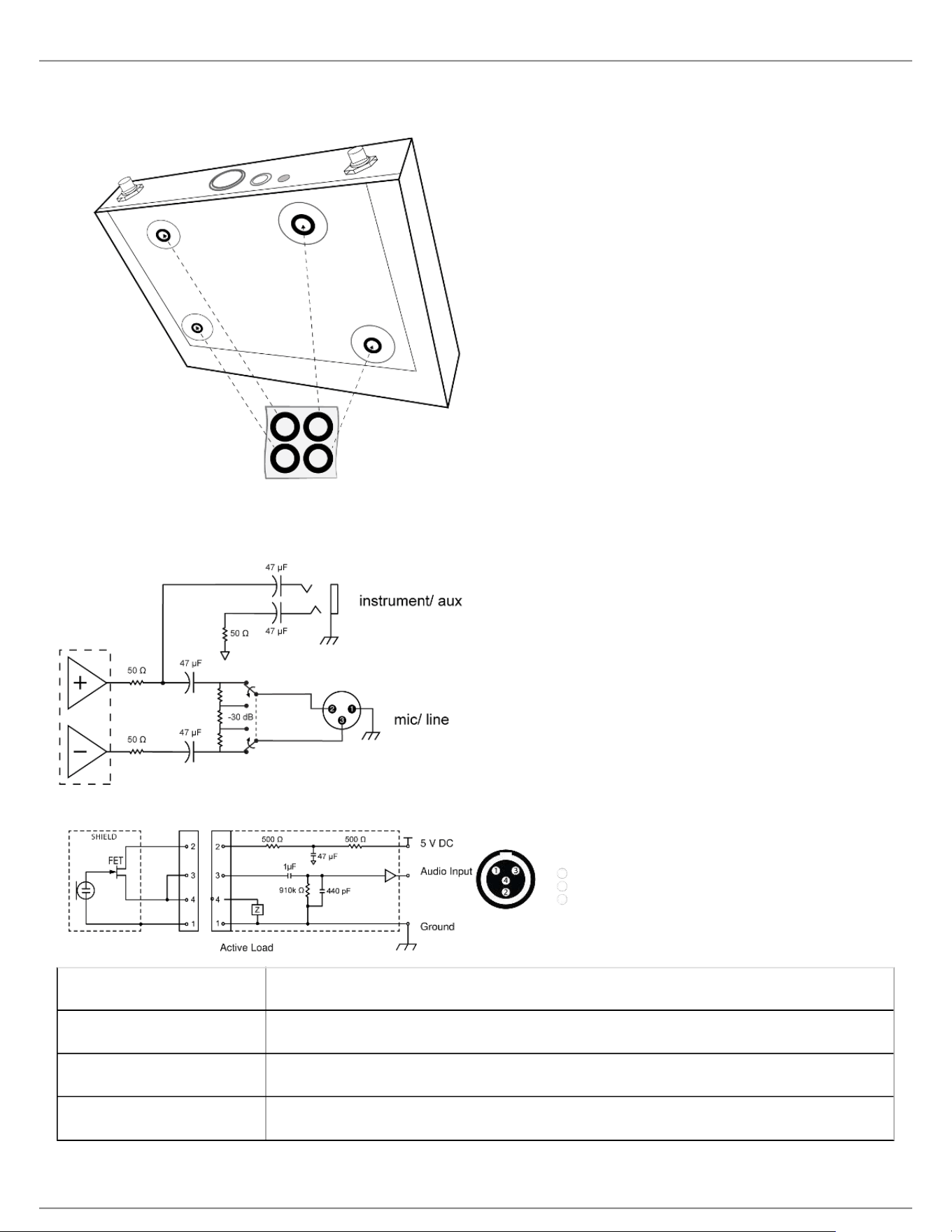
Receiver Output Connectors
Transmitter Input
① Ground
② Bias Voltage
③ Audio Input
④ Ground

Shure Incorporated
41/60
Accessories
Optional Accessories
Batteries and Chargers
Shure Lithium-Ion Rechargeable Battery SB900
8-Pack Shure Lithium-Ion Rechargeable Batteries SB900-8
8-Bay Shure Battery Charger SBC800-US
Dual Docking Charger With PS45US Power Supply SBC200-US
Dual Docking Charger, Power Supply Not Included SBC200
Single Battery Charger SBC100
Axient Charging Module SBC-AX
2-Bay Portable Battery Charger With PS50US Power
Supply
SBC210
Bodypack Power Insert SBC-DC
Active Antenna Splitters
Antenna Distribution System UA845 E
Antenna Distribution System UA845 E "B"
Antenna Distribution System UA845J
Antenna UHF-R 470-952 MHz UA845-SWB
Antenna,Power Dist UHF-R 470-952 MHz UA845-SWB-AZ
Antenna UHF-R 470-952 MHz UA845-SWB-BR
Antenna,Power Dist UHF-R 470-952 MHz UA845-SWB-C
Antenna,Power Dist UHF -R 470-952 MHz UA845-SWB-E
Antenna UHF-R 470-952 MHz UA845-SWB-K
Antenna, Power Dist UHF-R 470-952 MHz UA845US
Shure Incorporated
42/60
UHF Antenna Power Distribution Amplifiers
UHF Wideband Antenna Distributor w/o Power Cables UA844SWB/LC
UHF Antenna Power Distribution System UA844SWB/LC-AR
UHF Antenna Power Distribution System UA844SWB/LC-BR
UHF Antenna Power Distribution System UA844SWB/LC-AZ
UHF Antenna Power Distribution System UA844SWB/LC-C
UHF Antenna Power Distribution System UA844SWB/LC-E
UHF Antenna Power Distribution Amplifier UA844SWB/LC-J
UHF Antenna Power Distribution Amplifier UA844SWB/LC-K
UHF Antenna Power Distribution Amplifier UA844SWB/LC-UK
UABIAST
In-Line Power Supply UABIAST-US
UABIAST-UK
UABIAST-BR
UABIAST-AR
UABIAST-E
UABIAST-CHN
UABIAST-K
UABIAST-J
UABIAST-AZ
UABIAST-TW
In-Line Amplifiers and Antennas
In-Line Antenna Amplifier, 792-810 MHz UA830A
In-Line Antenna Amplifier, 470-698MHz UA830USTV

Shure Incorporated
43/60
In-Line Antenna Amplifier, 500-900 MHz UA830WB
In-Line Antenna Amplifier UA830X
Active Directional Antenna 470-790MHZ UA874E
Active Directional Antenna 470-698MHZ UA874US
Active Directional Antenna 470-900MHZ UA874WB
Active Directional Antenna 925-952MHZ UA874X
Directional Wideband Antenna for PSM Systems PA805SWB
Directional Wideband Antenna for PSM Systems PA805X
Passive Omnidirectional Antenna UA860SWB
UHF Passive Antenna Splitter UA221
Front Mount Antenna Kit (Includes 2 Cables And 2
Bulkhead)
UA600
Remote Antenna Bracket With BNC Bulkhead Adaptor UA505
Helical Antenna, 470-900MHZ HA-8089
Helical Antenna, 944-952MHZ HA-8241
Cables and Connectors
Coaxial Cable, BNC-BNC, RG58C/U TYPE, 50 OHM,
2 FT Length (0.6 M)
UA802
Coaxial Cable, BNC-BNC, RG58C/U TYPE, 50 OHM,
6 FT Length (2 M)
UA806
Coaxial Cable, BNC-BNC, RG8X/U TYPE, 50 OHM, 25
FT Length (7.5 M)
UA825
Coaxial Cable, BNC-BNC, RG8X/U TYPE, 50 OHM, 50
FT Length (15 M)
UA850
Coaxial Cable, BNC-BNC, RG213/U TYPE, 50 OHM,
100 FT Length (30 M)
UA8100
Ethernet Jumper Cable, 8" C8006

Shure Incorporated
44/60
Ethernet Cable, 3 FT. C803
Ethernet Cable, 10 FT. C810
Ethernet Cable, Ruggedized, 100 FT. C8100
Ethernet Cable, Ruggedized, 25 FT. C825
Ethernet Cable, Ruggedized, 50 FT. C850
1/2 Wave Omnidirectional Receiver Antennas
470-542 MHz UA8-470-542
500-560 MHz UA8-500-560
518-598 MHz UA8-518-598
554-638 MHz UA8-554-638
596-698 MHz UA8-596-698
670-742 MHz UA8-670-742
690-746 MHz UA8-690-746
694-758 MHz UA8-694-758
710-790 MHz UA8-710-790
740-814 MHz UA8-740-814
750-822 MHz UA8-750-822
774-865 MHz UA8-774-865
00-1000 MHz UA8-900-1000
Hardware, Cases, and Accessories
Hard Carrying Case For SLX System WA610
Anti-Roll Device for Handheld Microphones A1K
Mute Switch for Shure Handheld Transmitters UAMS/BK

Shure Incorporated
45/60
Cable, Instrument, 2.5 foot (.75 m), 4 Pin Mini
Connector (TA4F) to 1/4-inch Connector.
WA302
Cable, Instrument, 2-foot (0.7m), 4-pin Mini Connector
(TA4F) with Right-Angle 1/4-inch Connector, used with
Shure Wireless Bodypack Transmitters
WA304
Premium Guitar Cable TQG Threaded Connector WA305
Premium Guitar Cable TQG Latching Connector WA306
Cable, Microphone, 4-foot (1.3m), 4-pin Mini
Connector (TA4F) to XLR Connector (F), used with
Shure Bodypack Transmitters.
WA310
In-line audio mute switch for Shure wireless bodypack
transmitters with a TA4F connector.
WA360
In-Line Bodypack Mute Switch WA661
Securely mounts the Shure wireless handheld
transmitters to standard microphone stands.
WA371
Neoprene bodypack arm pouch for all Shure bodypack
transmitters
WA620
Hardware, Cases, and Accessories
Hard Carrying Case For SLX System WA610
Anti-Roll Device for Handheld Microphones A1K
Mute Switch for Shure Handheld Transmitters UAMS/BK
Cable, Instrument, 2.5 foot (.75 m), 4 Pin Mini Connector (TA4F) to 1/4-inch
Connector.
WA302
Cable, Instrument, 2-foot (0.7m), 4-pin Mini Connector (TA4F) with Right-Angle
1/4-inch Connector, used with Shure Wireless Bodypack Transmitters
WA304
Premium Guitar Cable TQG Threaded Connector WA305
Premium Guitar Cable TQG Latching Connector WA306
Cable, Microphone, 4-foot (1.3m), 4-pin Mini Connector (TA4F) to XLR Connector
(F), used with Shure Bodypack Transmitters.
WA310

Shure Incorporated
46/60
In-line audio mute switch for Shure wireless bodypack transmitters with a TA4F
connector.
WA360
In-Line Bodypack Mute Switch WA661
Securely mounts the Shure wireless handheld transmitters to standard
microphone stands.
WA371
Neoprene bodypack arm pouch for all Shure bodypack transmitters WA620
Cables and Connectors
Coaxial Cable, BNC-BNC, RG58C/U TYPE, 50 OHM, 2 FT Length (0.6 M) UA802
Coaxial Cable, BNC-BNC, RG58C/U TYPE, 50 OHM, 6 FT Length (2 M) UA806
Coaxial Cable, BNC-BNC, RG8X/U TYPE, 50 OHM, 25 FT Length (7.5 M) UA825
Coaxial Cable, BNC-BNC, RG8X/U TYPE, 50 OHM, 50 FT Length (15 M) UA850
Coaxial Cable, BNC-BNC, RG213/U TYPE, 50 OHM, 100 FT Length (30 M) UA8100
Ethernet Jumper Cable, 8" C8006
Ethernet Cable, 3 FT. C803
Ethernet Cable, 10 FT. C810
Ethernet Cable, Ruggedized, 100 FT. C8100
Ethernet Cable, Ruggedized, 25 FT. C825
Ethernet Cable, Ruggedized, 50 FT. C850
In-Line Amplifiers and Antennas
In-Line Antenna Amplifier, 792-810 MHz UA830A
In-Line Antenna Amplifier, 470-698MHz UA830USTV
In-Line Antenna Amplifier, 500-900 MHz UA830WB
In-Line Antenna Amplifier UA830X
Active Directional Antenna 470-790MHZ UA874E

Shure Incorporated
47/60
Active Directional Antenna 470-698MHZ UA874US
Active Directional Antenna 470-900MHZ UA874WB
Active Directional Antenna 925-952MHZ UA874X
Directional Wideband Antenna for PSM Systems PA805SWB
Directional Wideband Antenna for PSM Systems PA805X
Passive Omnidirectional Antenna UA860SWB
UHF Passive Antenna Splitter UA221
Front Mount Antenna Kit (Includes 2 Cables And 2 Bulkhead) UA600
Remote Antenna Bracket With BNC Bulkhead Adaptor UA505
Helical Antenna, 470-900MHZ HA-8089
Helical Antenna, 944-952MHZ HA-8241
UHF Antenna Power Distribution Amplifiers
UHF Wideband Antenna Distributor w/o Power Cables UA844SWB/LC
UHF Antenna Power Distribution System UA844SWB/LC-AR
UHF Antenna Power Distribution System UA844SWB/LC-BR
UHF Antenna Power Distribution System UA844SWB/LC-AZ
UHF Antenna Power Distribution System UA844SWB/LC-C
UHF Antenna Power Distribution System UA844SWB/LC-E
UHF Antenna Power Distribution Amplifier UA844SWB/LC-J
UHF Antenna Power Distribution Amplifier UA844SWB/LC-K
UHF Antenna Power Distribution Amplifier UA844SWB/LC-UK
Active Antenna Splitters
Antenna Distribution System UA845 E

Shure Incorporated
48/60
Antenna Distribution System UA845 E "B"
Antenna Distribution System UA845J
Antenna UHF-R 470-952 MHz UA845-SWB
Antenna,Power Dist UHF-R 470-952 MHz UA845-SWB-AZ
Antenna UHF-R 470-952 MHz UA845-SWB-BR
Antenna,Power Dist UHF-R 470-952 MHz UA845-SWB-C
Antenna,Power Dist UHF -R 470-952 MHz UA845-SWB-E
Antenna UHF-R 470-952 MHz UA845-SWB-K
Antenna, Power Dist UHF-R 470-952 MHz UA845US
Batteries and Chargers
Shure Lithium-Ion Rechargeable Battery SB900
8-Pack Shure Lithium-Ion Rechargeable Batteries SB900-8
8-Bay Shure Battery Charger SBC800-US
Dual Docking Charger With PS45US Power Supply SBC200-US
Dual Docking Charger, Power Supply Not Included SBC200
Single Battery Charger SBC100
Axient Charging Module SBC-AX
2-Bay Portable Battery Charger With PS50US Power Supply SBC210
Bodypack Power Insert SBC-DC
Black Bodypack Pouch WA582B
Specifications
RF Carrier Frequency Range
470–937.5 MHz, varies by region (See Frequency Range and Output Power table)

Shure Incorporated
49/60
Working Range
100 m (328 ft)
RF Tuning Step Size
25 kHz, varies by region
Image Rejection
>70 dB, typical
RF Sensitivity
-97 dBm at 10 BER
Latency
<2.9 ms
Audio Frequency Response
QLXD1 20 – 20 kHz (±1 dB)
QLXD2 Note: Dependent on microphone type
Audio Dynamic Range
System Gain @ +10
>120 dB, A-weighted, typical
Total Harmonic Distortion
−12 dBFS input, System Gain @ +10
<0.1%
System Audio Polarity
Positive pressure on microphone diaphragm produces positive voltage on pin 2 (with respect to pin 3 of XLR output)
and the tip of the 6.35 mm (1/4-inch) output.
Operating Temperature Range
-18°C (0°F) to 50°C (122°F)
Storage Temperature Range
-29°C (-20°F) to 74°C (165°F)
Dimensions
41 mm x 197 mm x 151 mm (1.63 in. x 7.75 in. x 5.94 in.), H x W x D

Shure Incorporated
50/60
Weight
777 g (1.71 lbs), without antennas
Housing
steel
Power Requirements
12 V DC @ 0.4 A, supplied by external power supply (tip positive)
RF Input
Spurious Rejection
>80 dB, typical
Connector Type
BNC
Impedance
50 Ω
Audio Output
Gain Adjustment Range
-18 to +42 dB in 1 dB steps
Configuration
1/4" (6.35 mm) Impedance balanced (Tip=audio, Ring=no
audio, Sleeve=ground)
XLR balanced (1=ground, 2=audio +, 3=audio −)
Impedance
1/4" (6.35 mm) 100 Ω (50 Ω Unbalanced)
XLR 100 Ω
Full Scale Output
1/4" (6.35 mm) +12 dBV

Shure Incorporated
51/60
XLR LINE setting= +18 dBV, MIC setting= -12
dBV
Mic/Line Switch
30 dB pad
Phantom Power Protection
1/4" (6.35 mm) Yes
XLR Yes
Networking
Network Interface
Single Port Ethernet 10/100 Mbps
Network Addressing Capability
DHCP or Manual IP address
Maximum Cable Length
100 m (328 ft)
Mic Offset Range
0 to 21 dB (in 3 dB steps)
Battery Type
Shure SB900 Rechargeable Li-Ion or AA batteries 1.5 V
Dimensions
86 mm x 65 mm x 23 mm (3.38in. x 2.57 in. x 0.92 in.) H x W x D , without antenna
Weight
138 g (4.9 oz.), without batteries
Housing
Cast aluminum
Audio Input
Connector
4-Pin male mini connector (TA4M), See drawing for details

Shure Incorporated
52/60
Configuration
Unbalanced
Impedance
1 MΩ, See drawing for details
Maximum Input Level
1 kHz at 1% THD
8.5 dBV (7.5 Vpp)
Preamplifier Equivalent Input Noise (EIN)
System Gain Setting ≥ +20
-120 dBV, A-weighted, typical
RF Output
Connector
SMA
Antenna Type
1/4 wave
Impedance
50 Ω
Occupied Bandwidth
<200 kHz
Modulation Type
Shure proprietary digital
Power
1 mW or 10 mW
Mic Offset Range
0 to 21 dB (in 3 dB steps)
Battery Type
Shure SB900 Rechargeable Li-Ion or AA batteries 1.5 V

Shure Incorporated
53/60
Dimensions
269 mm x 51 mm (10.6 in. x 2.0 in.) L x Dia.
Weight
307 g (12.1 oz.), without batteries
Housing
Machined aluminum
Audio Input
Configuration
Unbalanced
Maximum Input Level
1 kHz at 1% THD
145 dB SPL (SM58), typical
RF Output
Antenna Type
Integrated Single Band Helical
Occupied Bandwidth
<200 kHz
Modulation Type
Shure proprietary digital
Power
1 mW or 10 mW
Frequency Range and Transmitter Output Power
Band Frequency Range (MHz)
Power (mW RMS )*
(Lo/Nm/Hi)
G50 470 to 534 1 / 10
G51 470 to 534 1 / 10
G52 479 to 534 1 / 10

Shure Incorporated
54/60
Band Frequency Range (MHz)
Power (mW RMS )*
(Lo/Nm/Hi)
G62 510 to 530 1 / 10
H50 534 to 598 1 / 10
H51 534 to 598 1 / 10
H52 534 to 565 1 / 10
H53 534 to 598 1 / 10
J50 572 to 636 1 / 10
J51 572 to 636 1 / 10
JB 806 to 810 1 / 10
K51 606 to 670 1 / 10
K52 606 to 670 1 / 10
L50 632 to 696 1 / 10
L51 632 to 696 1 / 10
L52 632 to 694 1 / 10
L53 632 to 714 1 / 10
P51 710 to 782 1 / 10
P52 710 to 782 1 / 10
Q51 794 to 806 1 / 10
S50 (823 to 832) (863 to 865) 1 / 10
V50 174 to 216 1 / 10
V51 174 to 216 1 / 10
X51 925 -937.5 1 / 10
X52 902 to 928 (All America's except
Brazil)
1 / 10

Shure Incorporated
55/60
Band Frequency Range (MHz)
Power (mW RMS )*
(Lo/Nm/Hi)
X53 902 to 907.500, 915 to 928 (Brazil) 1 / 10
X54 915 to 928 (Australia) 1 / 10
Z17 1492 to 1525 1 / 10
Z18 1785 to 1805 1 / 10
Z19 1785 to 1800 1 / 10
Z20 1790 to 1805 1 / 10
* Power delivered to the antenna port
Note: Frequency bands might not be available for sale or authorized for use in all countries or regions.
For the band Z17 (1492-1525 MHz), it must be used indoors only.
For the Band Z19 (1785-1800MHz) used in Australia, per Radio Communications Low Interference Potential
Devices Class License 2015; item 30 note C: the system must be operated within the range of 1790-1800MHz when
used outdoors.
Frequencies for European Countries
G51 470-534 MHz
Country Code
Code de Pays
Codice di paese
Código de país
Länder-Kürzel
Frequency Range
Gamme de frequences
Gamme di frequenza
Gama de frequencias
Frequenzbereich
A, B, BG, CH, CY, CZ, D, DK, EST, F *
FIN, GB, GR, H, HR, I, IRL, IS, L, LT *
M, N, NL, P, PL, RO, S, SK, SLO, TR *
All other countries *
* This equipment may be capable of operating on some frequencies not authorized in your region. See Licensing
Information.
Shure Incorporated
56/60
H51 534-598 MHz
Country Code
Code de Pays
Codice di paese
Código de país
Länder-Kürzel
Frequency Range
Gamme de frequences
Gamme di frequenza
Gama de frequencias
Frequenzbereich
A, B, BG, CH, CY, CZ, D, EST 534 - 598 MHz*
F, GB, GR, H, I, IS, L, LT 534 - 598 MHz*
NL, P, PL, S, SK, SLO 534 - 598 MHz*
DK, FIN, M, N *
HR, E, IRL, LV, RO, TR *
All other countries *
* This equipment may be capable of operating on some frequencies not authorized in your region. See Licensing
Information.
K51 606-670 MHz
Country Code
Code de Pays
Codice di paese
Código de país
Länder-Kürzel
Frequency Range
Gamme de frequences
Gamme di frequenza
Gama de frequencias
Frequenzbereich
A, B, BG, CH, CY, CZ, D, EST 606 - 670 MHz*
F, GB, GR, H, I, IS, L, LT 606 - 670 MHz*
NL, P, PL, S, SK, SLO 606 - 670 MHz*
RO 646 - 647; 654 - 655; 662 - 663 MHz*
DK, E, FIN, HR, IRL, LV, M, N, TR *
All other countries *

Shure Incorporated
57/60
* This equipment may be capable of operating on some frequencies not authorized in your region. See Licensing
Information.
L52 632-694 MHz
Country Code
Code de Pays
Codice di paese
Código de país
Länder-Kürzel
Frequency Range
Gamme de frequences
Gamme di frequenza
Gama de frequencias
Frequenzbereich
A, B, BG, CH, CY, CZ, D, DK, EST, F *
FIN, GB, GR, H, HR, I, IRL, IS, L, LT *
M, N, NL, P, PL, RO, S, SK, SLO, TR *
All other countries *
* This equipment may be capable of operating on some frequencies not authorized in your region. See Licensing
Information.
P51 710-782 MHz
Country Code
Code de Pays
Codice di paese
Código de país
Länder-Kürzel
Frequency Range
Gamme de frequences
Gamme di frequenza
Gama de frequencias
Frequenzbereich
A, B, BG, CH, CY, CZ, D, EST, F, GB 710 - 782 MHz*
GR, H, I, IS, L, LT, NL, P, PL, S, SK, SLO 710 - 782 MHz*
RO 718 - 719; 726 - 727; 734 - 743; 750 - 751; 758 -
759 MHz*
DK, E, FIN, HR, IRL, LV, M, N, TR *
All other countries *
* This equipment may be capable of operating on some frequencies not authorized in your region. See Licensing
Information.

Shure Incorporated
58/60
Q51 794-806 MHz
Country Code
Code de Pays
Codice di paese
Código de país
Länder-Kürzel
Frequency Range
Gamme de frequences
Gamme di frequenza
Gama de frequencias
Frequenzbereich
A, B, BG, CH, CY, CZ, D, DK, E, EST *
F, FIN, GB, GR, H, HR, I, IRL, IS, L, LT *
LV, M, N, NL, P, PL, S, SK, SLO, TR *
All other countries *
* This equipment may be capable of operating on some frequencies not authorized in your region. See Licensing
Information.
S50 823-832 MHz, 863-865 MHz
Country Code
Code de Pays
Codice di paese
Código de país
Länder-Kürzel
Frequency Range
Gamme de frequences
Gamme di frequenza
Gama de frequencias
Frequenzbereich
D license free
A, B, BG, CH, CY, CZ, D, DK, EST, F *
FIN, GB, GR, H, HR, I, IRL, IS, L, LT *
M, N, NL, P, PL, RO, S, SK, SLO, TR *
863 - 865 MHz EU: license free
All other countries *
* This equipment may be capable of operating on some frequencies not authorized in your region. See Licensing
Information.

Shure Incorporated
59/60
•
•
Battery Life
QLXD
SB900A alkaline
1/10mW 1/10mW
470 to 865 >9:30 hours 8 hours
902 to 928 >8:30 hours >6 hours
174 to 216 >9:30 hours >8:30 hours
1240 to 1800 >8:00 hours >6 hours
The values in this table are typical of fresh, high quality batteries. Battery runtime varies depending on the
manufacturer and age of the battery.
Certifications
Meets essential requirements of the following European Directives:
WEEE Directive 2002/96/EC, as amended by 2008/34/EC
RoHS Directive 2011/65/EU
Note: Please follow your regional recycling scheme for batteries and electronic waste
Hereby, Shure Incorporated declares that the radio equipment is in compliance with Directive 2014/53/EU. The full
text of the EU declaration of conformity is available at the following internet address: http://www.shure.com/europe/
compliance (http://www.shure.com/europe/compliance)
Authorized European representative:
Shure Europe GmbH
Headquarters Europe, Middle East & Africa
Department: EMEA Approval
Jakob-Dieffenbacher-Str. 12
75031 Eppingen, Germany
Phone: +49-7262-92 49 0
Fax: +49-7262-92 49 11 4
Email: [email protected]
Industry Canada ICES-003 Compliance Label: CAN ICES-3 (B)/NMB-3(B)
Certified under FCC Part 74.
Certified by IC in Canada under RSS-102 and RSS-210.
IC: 616A-QLXD1G50, 616A-QLXD1H50, 616A-QLXD1J50, 616A-QLXD1L50, 616A-QLXD2G50, 616A-QLXD2H50,
616A-QLXD2J50, 616A-QLXD2L50.

Shure Incorporated
60/60
FCC: DD4QLXD1G50, DD4QLXD1H50, DD4QLXD1J50, DD4QLXD1L50, DD4QLXD2G50, DD4QLXD2H50,
DD4QLXD2J50, DD4QLXD2L50.
IC: 616A-QLXD1X52, 616A-QLXD2X52
FCC: DD4QLXD1X52, DD4QLXD2X52
IC: 616A-QLXD1V50, 616A-QLXD2V50
FCC: DD4QLXD1V50, DD4QLXD2V50
Note: For transmitters operating in the V50 and V51 bands: nominal free space antenna gain at middle of the band
is typically -6 dBi, and rolls off at the band edges an additional -4 dB.
Approved under the Declaration of Conformity (DoC) provision of FCC Part 15.
Conforms to electrical safety requirements based on IEC 60065.

