
Technical Support and E-Warranty Certificate www.vevor.com/support
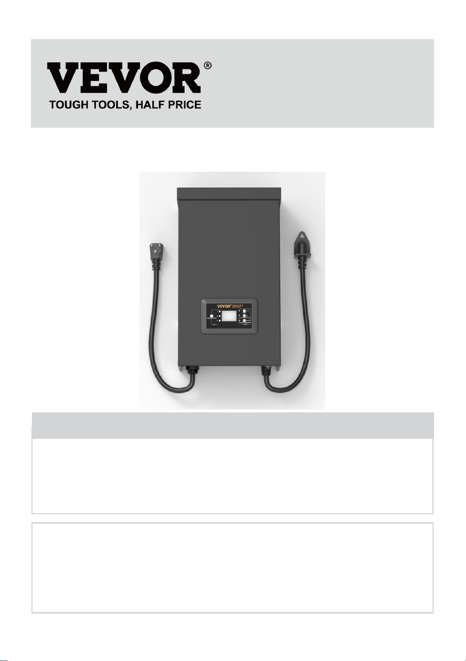
TRANSFORMER
USER MANUAL
We continue to be committed to providing you tools with competitive price.
"Save Half", "Half Price" or any other similar expressions used by us only represent an
estimate of savings you might benefit from buying certain tools with us compared to the major
top brands and does not necessarily mean to cover all categories of tools offered by us. You
are kindly reminded to verify carefully when you are placing an order with us if you are
actually saving half in comparison with the top major brands.


MODEL: HPN-120GK2301 HPN-200GK2302 HPN-300GK2303
HPN-600GK2306
Have product questions? Need technical support? Please feel free to
contact us:
Technical Support and E-Warranty Certificate
www.vevor.com/support
NEED HELP? CONTACT US!
This is the original instruction, please read all manual instructions
carefully before operating. VEVOR reserves a clear interpretation of our
user manual. The appearance of the product shall be subject to the
product you received. Please forgive us that we won't inform you again if
there are any technology or software updates on our product.
TRANSFORMER

SAFETY INFORMATION
IMPORTANT SAFETY INFORMATION TO REDUCE RISK OF FIRE OR
INJURY
Do not install within 10 feet ( 3 m ) of a pool , spa or fountain.
For use with low voltage outdoor landscape lighting systems only. There
are no serviceable parts inside the power supply unit.
DO NOT DISASSEMBLE.
Do not submerge the transformer.
Do not connect two or more transformers in parallel.
Do not use it with a dimmer.
Plug the power supply unit directly into a GFCI wet location outlet.
Do not use an extension cord.
WARNING :
Changes or modifications to this unit not expressly approved by the party
responsible for compliance could void the users' authority to operate the
equipment.
Note :
This equipment has been tested and found to comply with the limits for a
Class B digital device, pursuant to part 15 of the FCC Rules. These limits
are designed to provide reasonable protection against harmful interference
in a residential installation. This equipment generates, uses, and can
radiate radio frequency energy and, if not installed and used in accordance
with the instructions, may cause harmful interference to radio
communications. However, there is no guarantee that interference will not
occur in a particular installation. If this equipment does cause harmful
interference to radio or television reception, which can be determined by
turning the equipment off and on, the user is encouraged to try to correct
the interference by one or more of the following measures:
Reorient or relocate the receiving antenna. Increase the separation
between the equipment and the receiver.
Connect the equipment to an outlet on a circuit different from that to which
the receiver is connected.
Consult the dealer or an experienced radio.
Pre-installation
WARNING :
Use only CSA or UL-approved low-voltage cable. Failure to use at least 16
gauge minimum cable or install it as directed in these instructions may
result in a Risk of Fire or Electric Shock. Using a large cable will ensure
maximum light output.
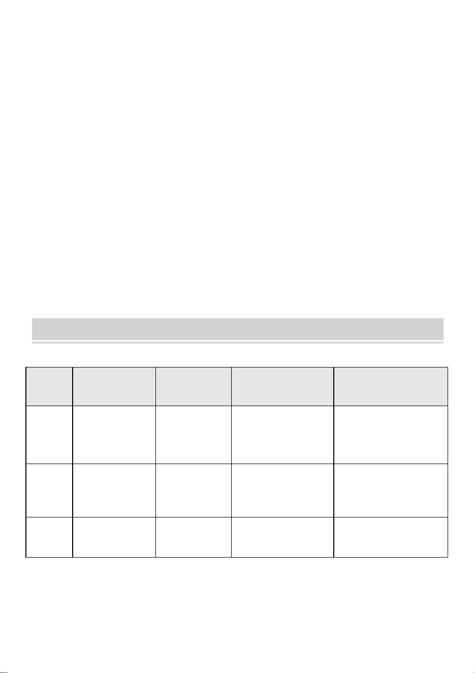
TECHNICAL PARAMETER
Model
HPN-120GK23
01
HPN-200GK2
302
HPN-300GK2303
HPN-600GK2306
Input
120VAC, 60Hz,
1.14A
120VAC,
60Hz,
1.8A
120VAC, 60Hz,
2.68A
120VAC, 60Hz,
5.45A
output
12VAC/10A
(MAX)
12VAC/16.7A
(MAX)
12VAC/25A~14VAC/
21.4A (MAX)
12VAC/50A~14VAC/42.
8A (MAX)
Power
120 W
200 W
300 W
600 W
Note: The transformer has three sets of outputs, each power set
accounting for one-third of the total power.
For example, The total power is 120W, and each output cannot exceed
40W; the total power is 200W, and each output cannot exceed 66W; the
total power is 300W, and each output cannot exceed 100W. The total
power is 600W, and each output cannot exceed 200W.
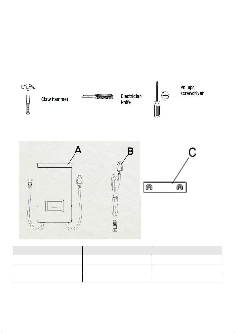
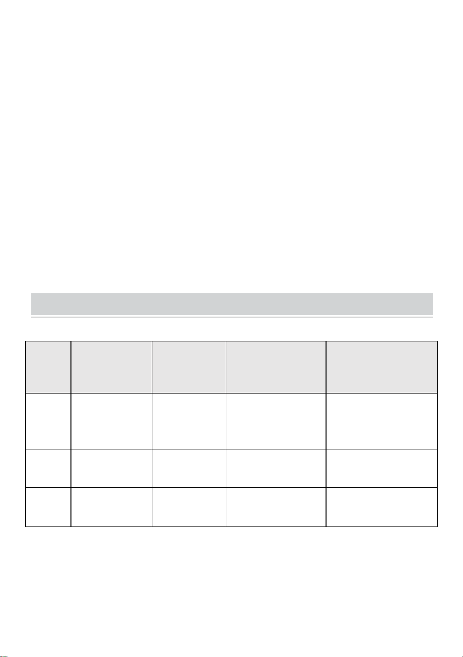
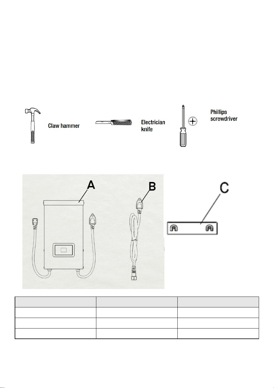
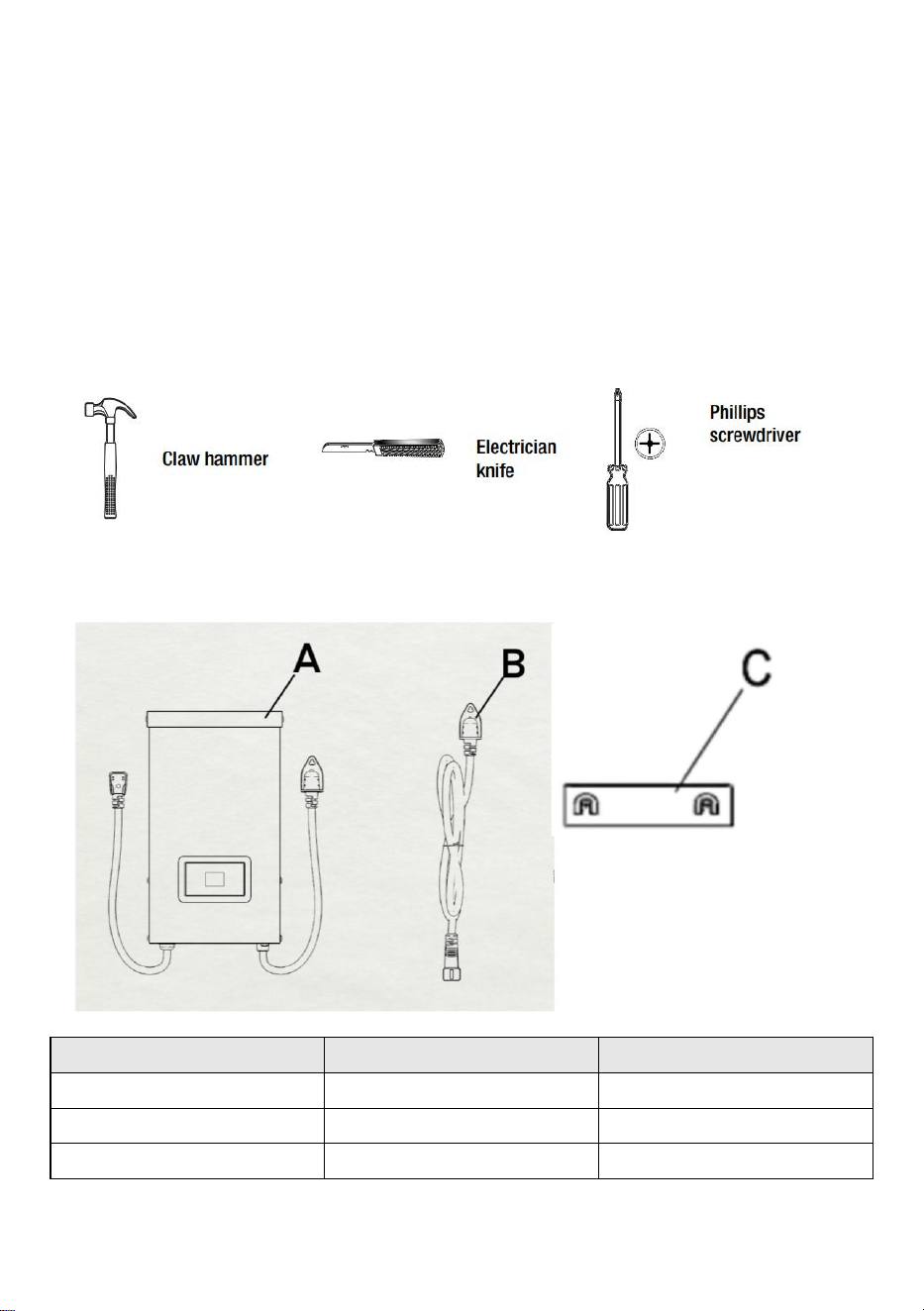
TOOLS REQUIRED
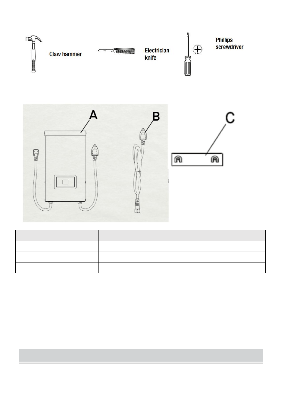
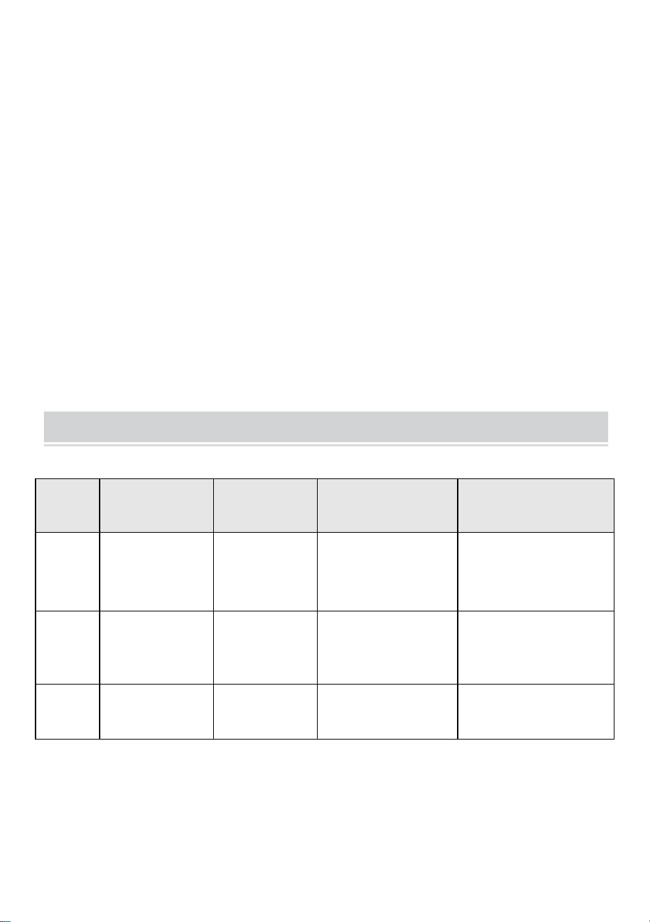
HARDWARE INCLUDED
Part
Description
Quantity
A
Transformer
1
B
Photocell
1
C
Mounting Template
1
NOTE: Hardware not shown to actual size.
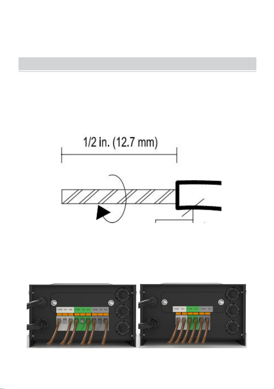
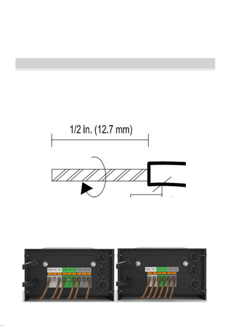
INSTALLATION
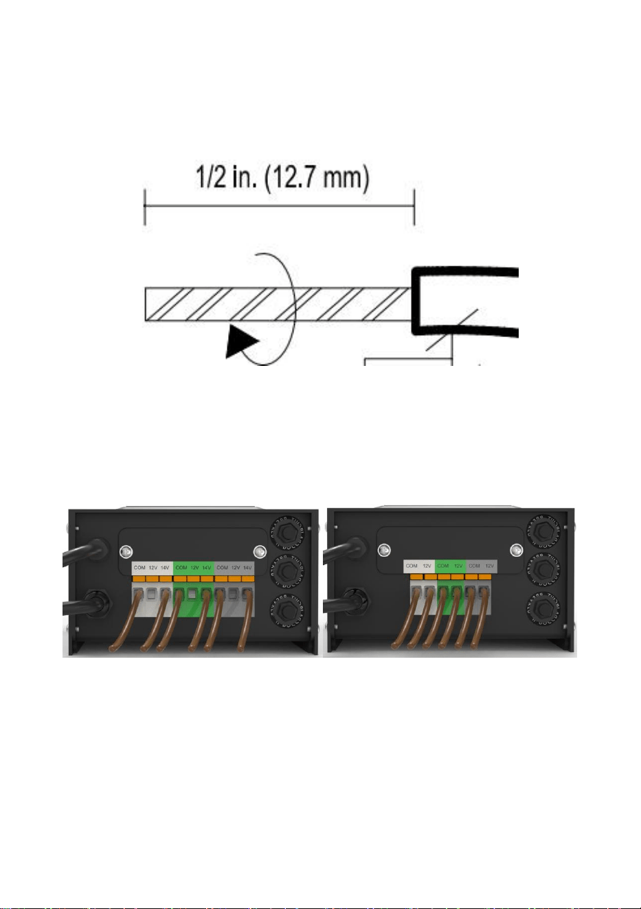
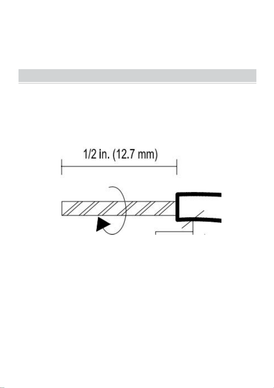
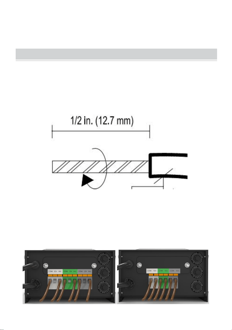
1、Preparing the Cable
Being careful when splitting NOT to expose the copper wire, remove the
landscape wire insulation 1/2 in. from both wires and twist ends.
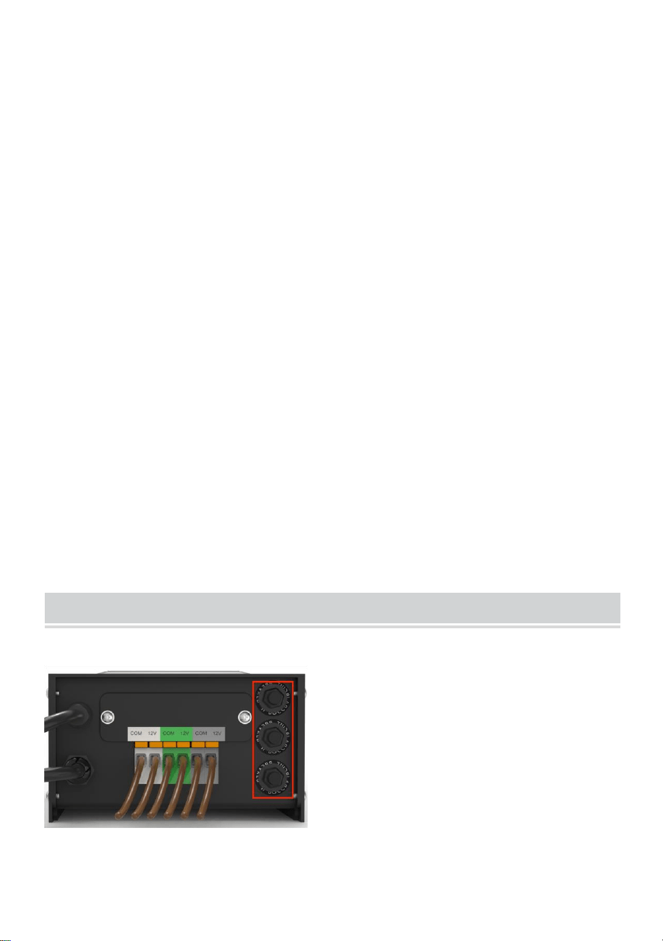
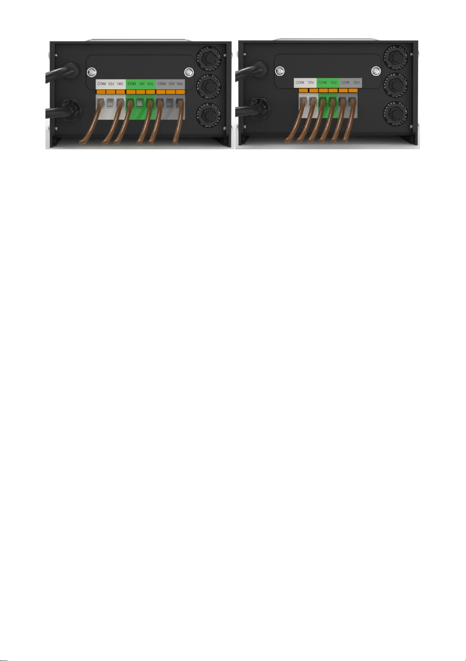
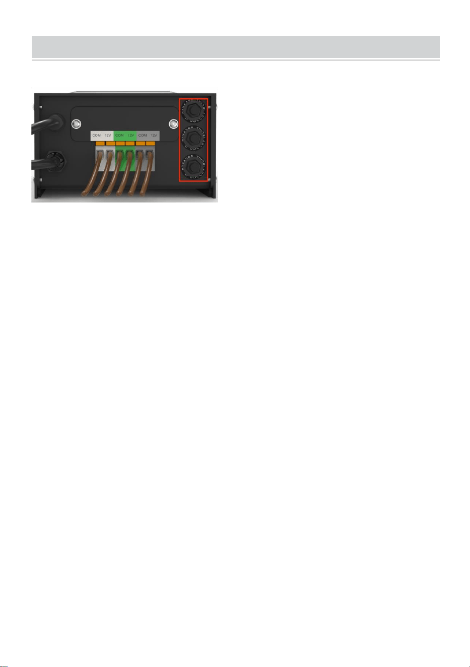
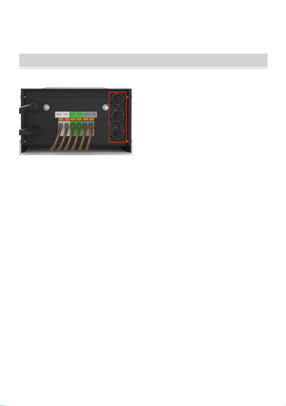
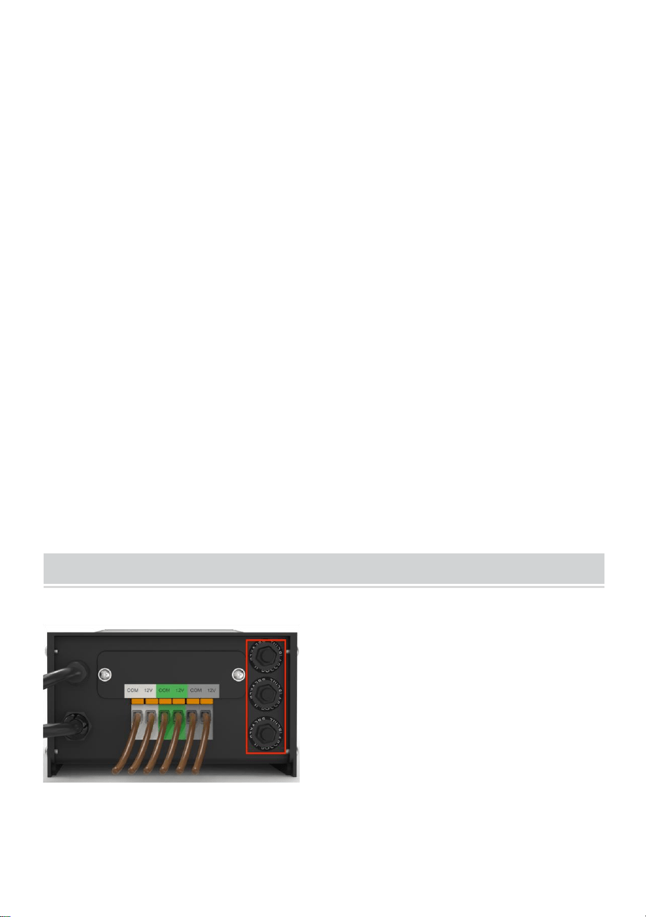
2、Connecting the Cable to the Transformer
Lay the transformer on a flat, stable surface and insert the stripped end of
one wire under the terminal clamping plate “COM”. Repeat this procedure
for clamping plate “12V” or “14V”.
3、NOTE: Gently pull on the landscape wire to verify if the connection
is strong.
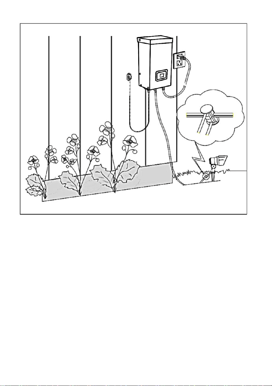
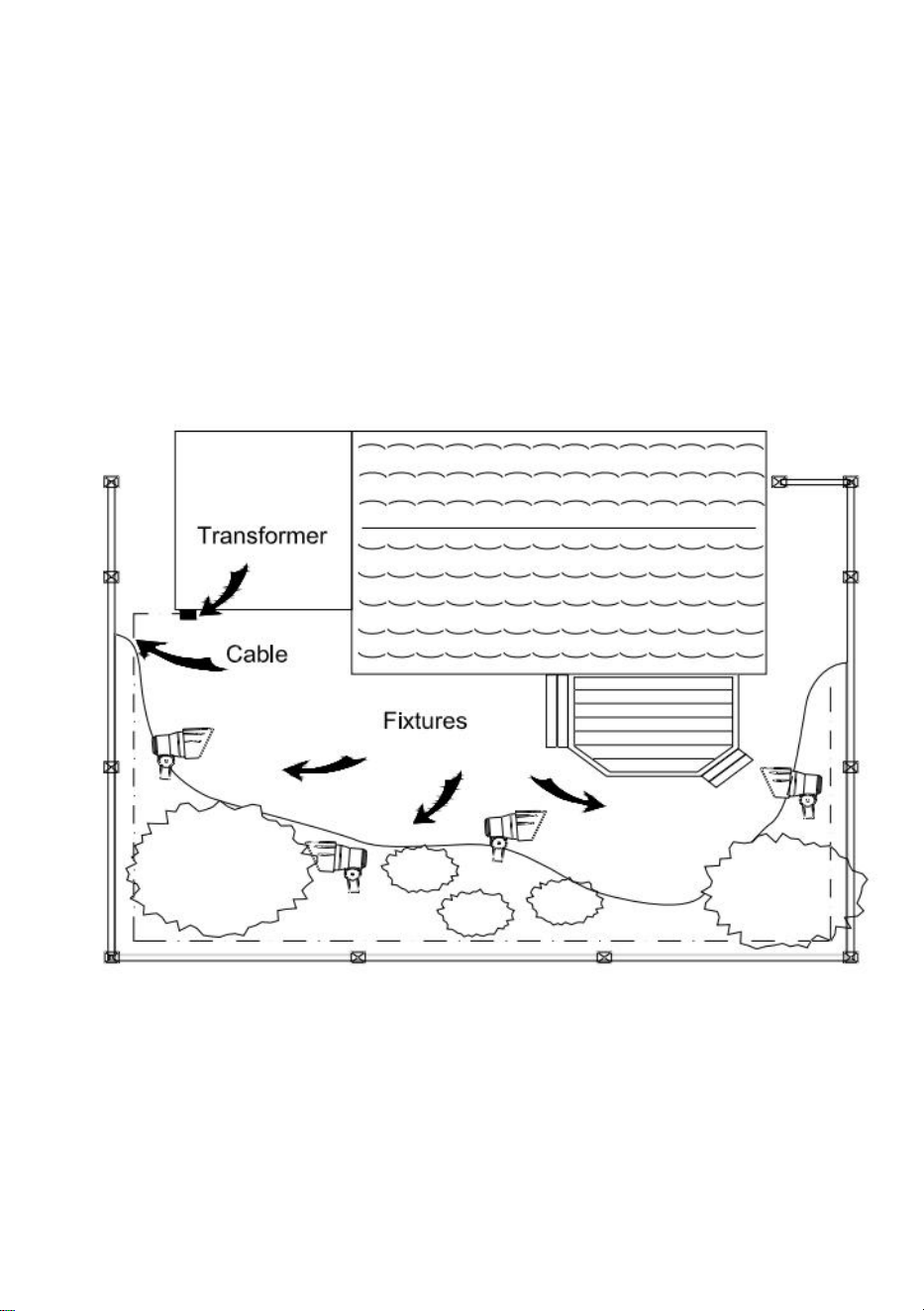
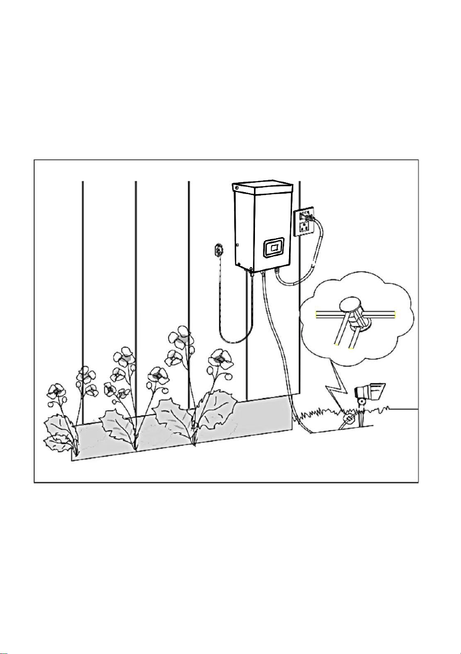
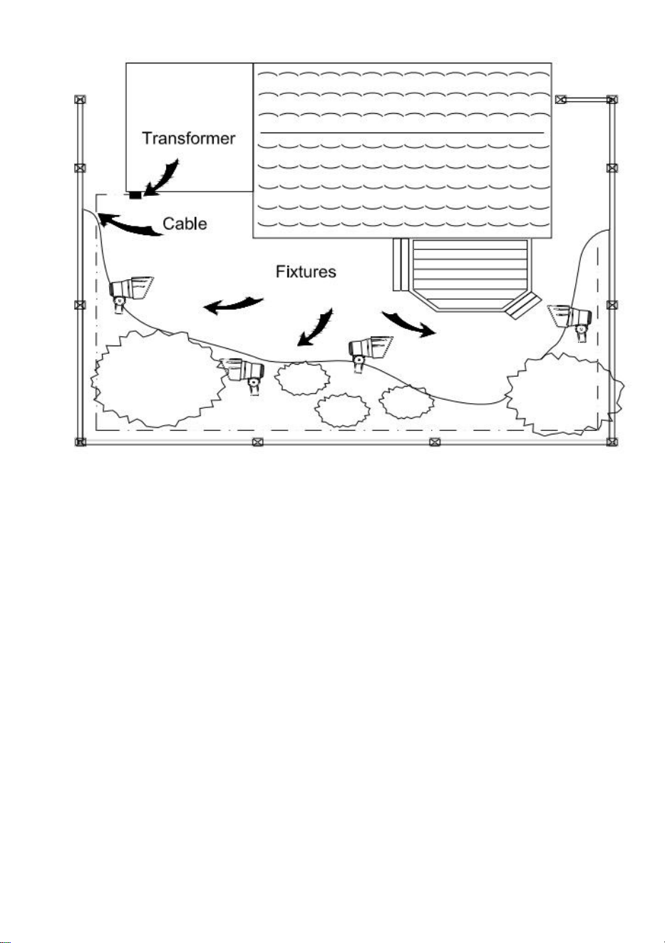
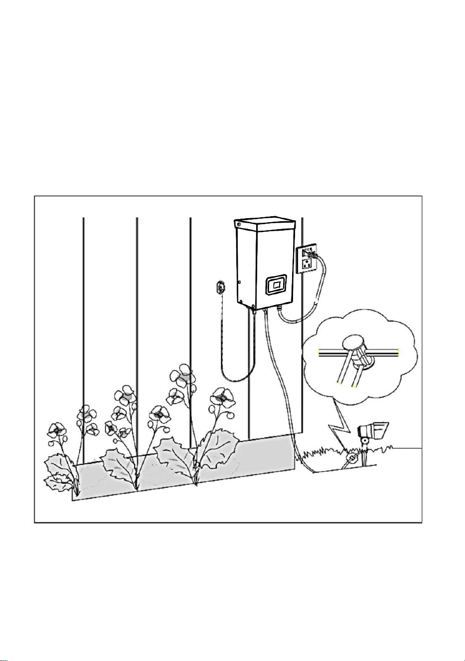
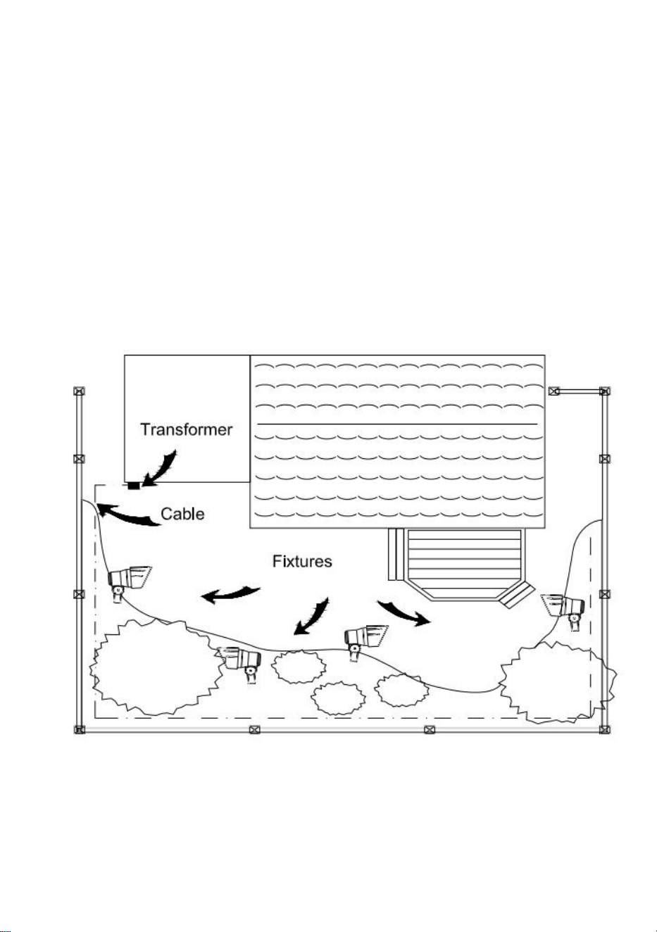
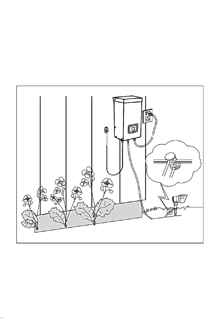
4、Placing Your Fixtures and Routing the Cable
Lay your fixtures (not included) out where you want to locate them. Be sure
they do not exceed the rating of the transformer. Route the low-voltage
cable to the fixtures; if there is extra cable, coil after the last fixture.
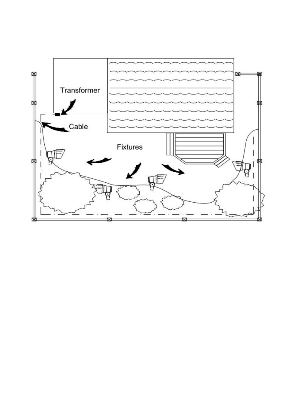
WARNING: Risk of Fire
Be sure to leave a minimum of 10 feet (3m) of wire between the power
pack and the first fixture.
5、Attaching Your Fixtures
Turn the transformer on. Attach your fixtures to the cable using cable
connectors as shown. Place one connector on each side of the cable, then
press together to lock. Prongs will pierce the cable to make contact, and
your fixtures should light up. Turn the transformer on. Attach your fixtures
to the cable using the cable connectors as shown. Press the connector
tight onto the cable until the prongs pierce the cable insulation. The fixture
should light
on.
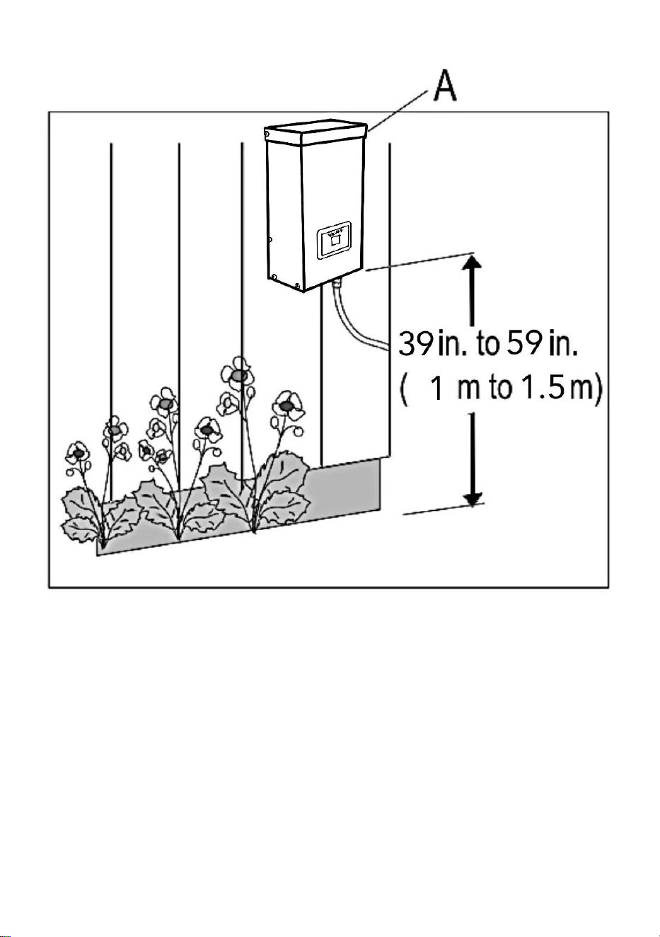
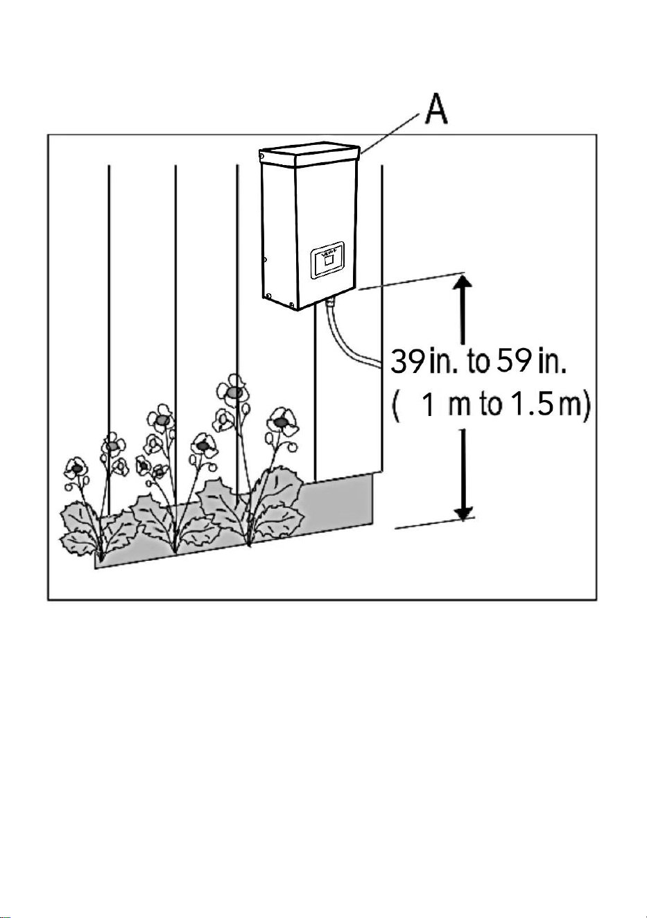
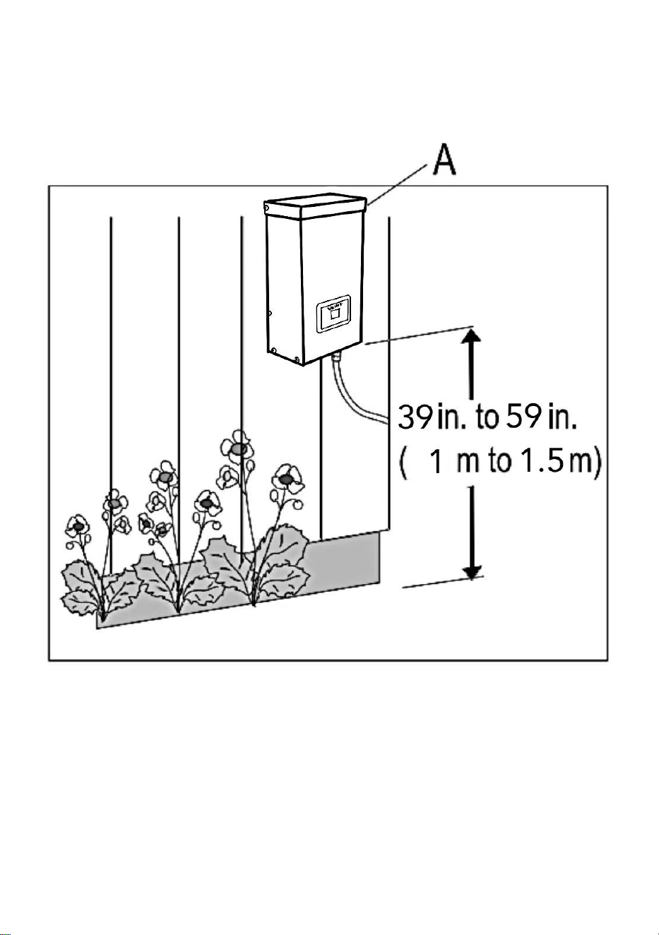
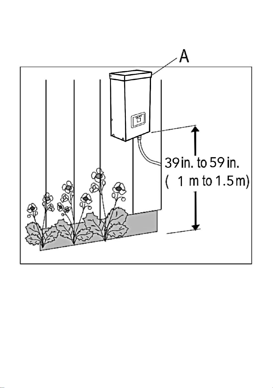
6、Mounting the Transformer
To mount directly to a wall surface, use the included screws as shown,
suitable for mounting within 39 in. to 59 in. (1 m to 1.5 m) of the ground.
When installing the screws, the spacing between the . Hang the
transformer (A) onto the screws.
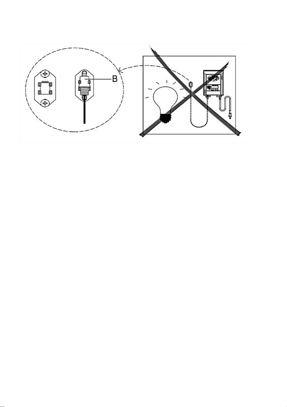
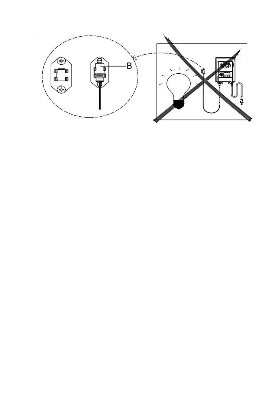
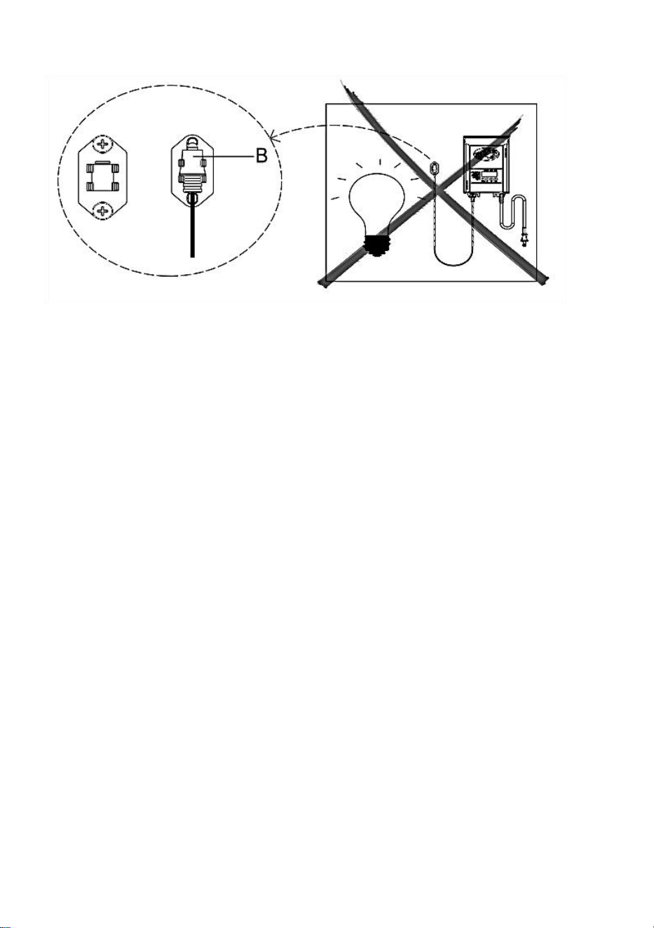
7、Mounting the Photocell
Mount the photocell (B) bracket on a wall or other solid surface. Snap the
sensor into the bracket. Route or coil the excess wire to protect it from
lawnmowers, trimmers, etc.
Avoid pointing the sensor at nighttime light sources such as windows,
porch lights, and street lights.

Placing the sensor in areas receiving less sunlight at dusk (east side
of the house, behind trees and bushes, under a deck) will have the
transformer come on earlier in the evening. Mounting the photocell in
brighter locations will have the transformer come on when it has become
darker out. The location, position, and orientation of the photocell can be
adjusted until the transformer turns on at the desired light level.
If the wires to the photocell are cut or broken, the photocell can be replaced.
Unscrew the photocell connector cover from the transformer and pull the
bi-pin connector out of the mating socket.
The replacement part is inserted into the socket, and the cap is screwed
back onto the socket to provide a water-tight connection.
Note that the bi-pin connector is polarized and can be inserted into the
socket only one way.
Replacement photocell is available in the store.
7、Protecting or Hiding the Cable
Once all fixtures are in place and you are satisfied with their
locations, the cable may be covered with mulch or buried up to
6 in. (15 cm) deep. Leave about 12 in. (30 cm) of cable after the
last fixture.
WARNING: Risk of Fire
Do not coil cable around the transformer. Total bulb wattages must not
exceed the maximum power of the
transformer.
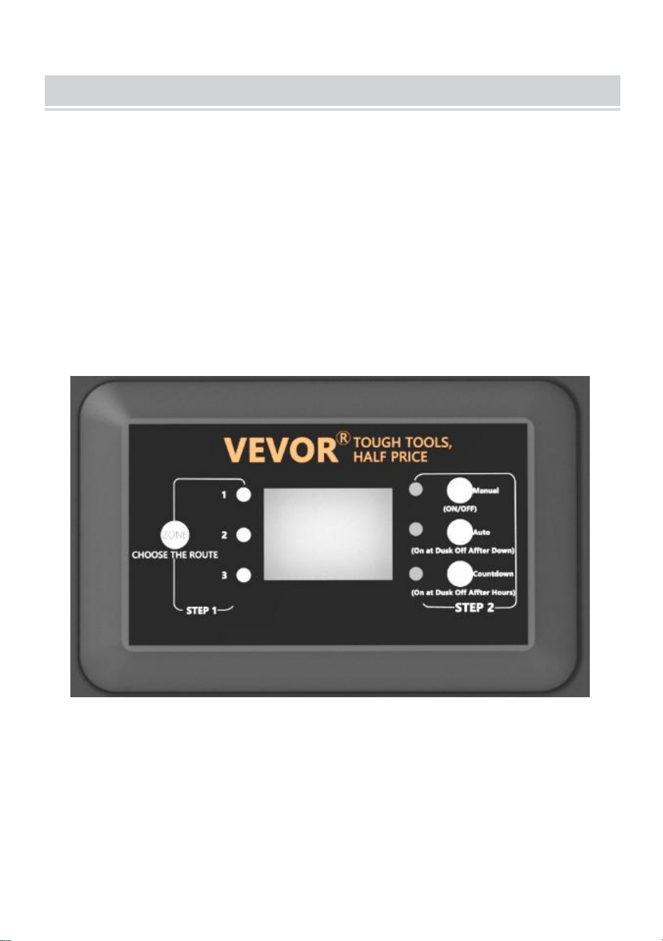
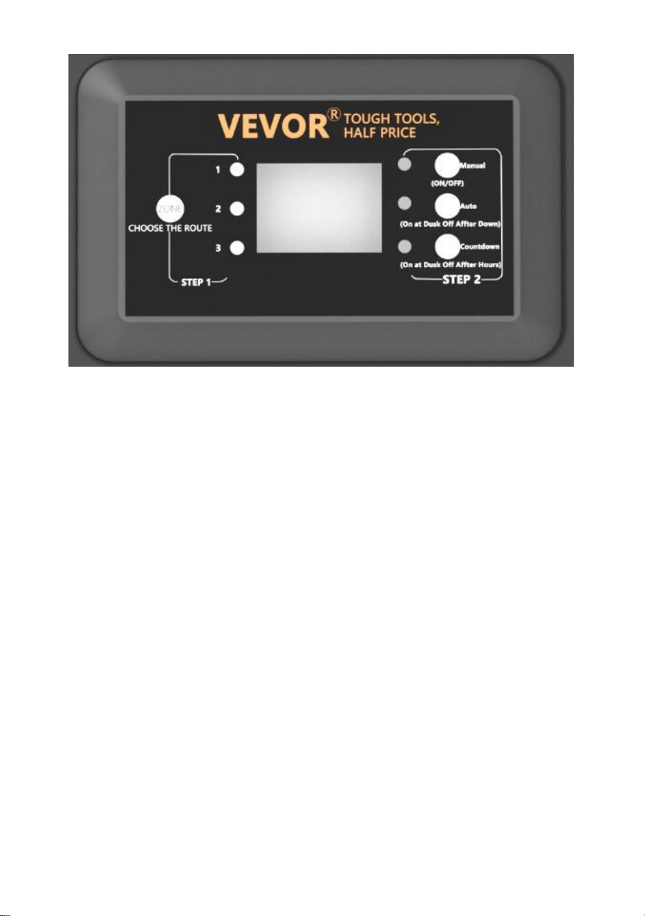
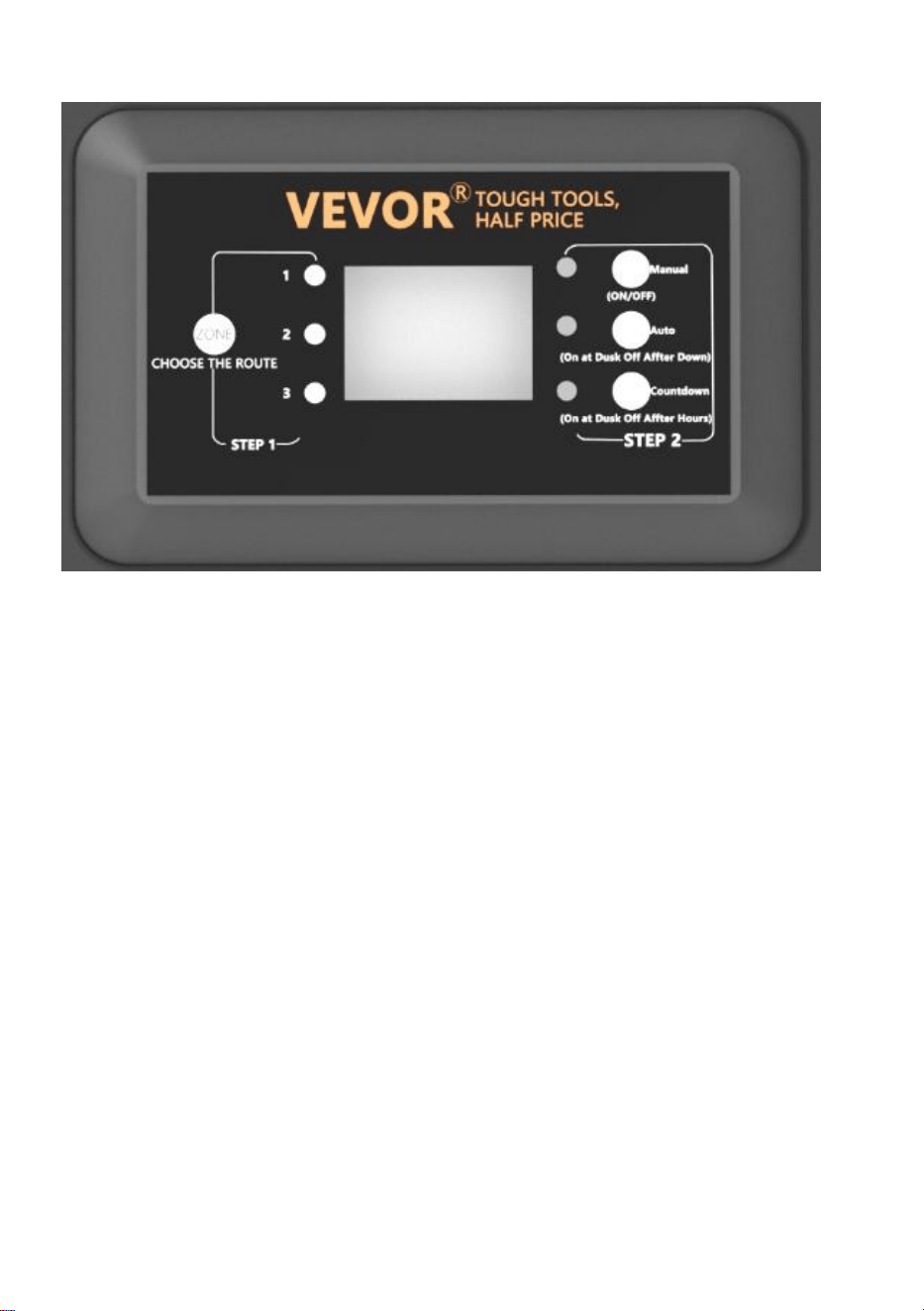
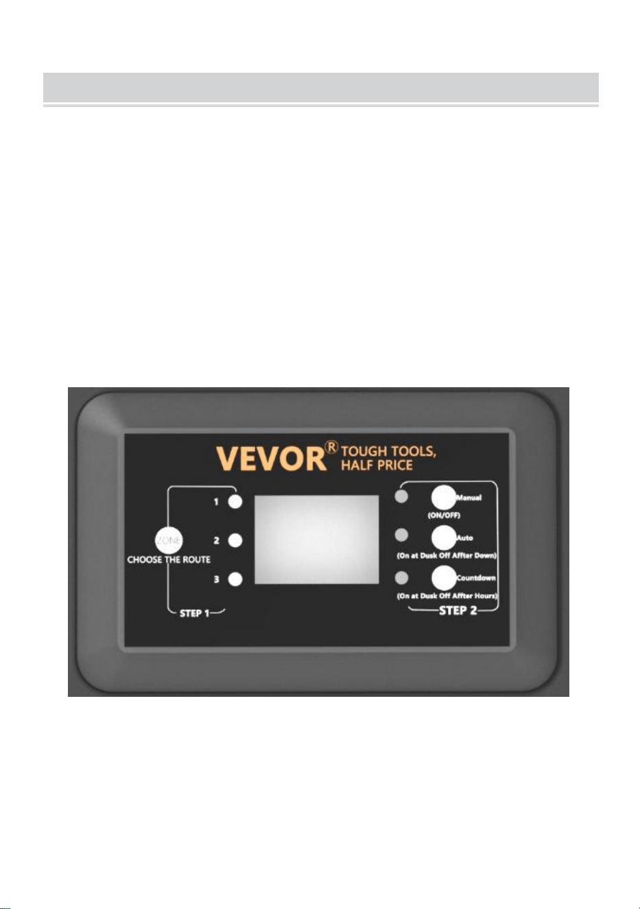
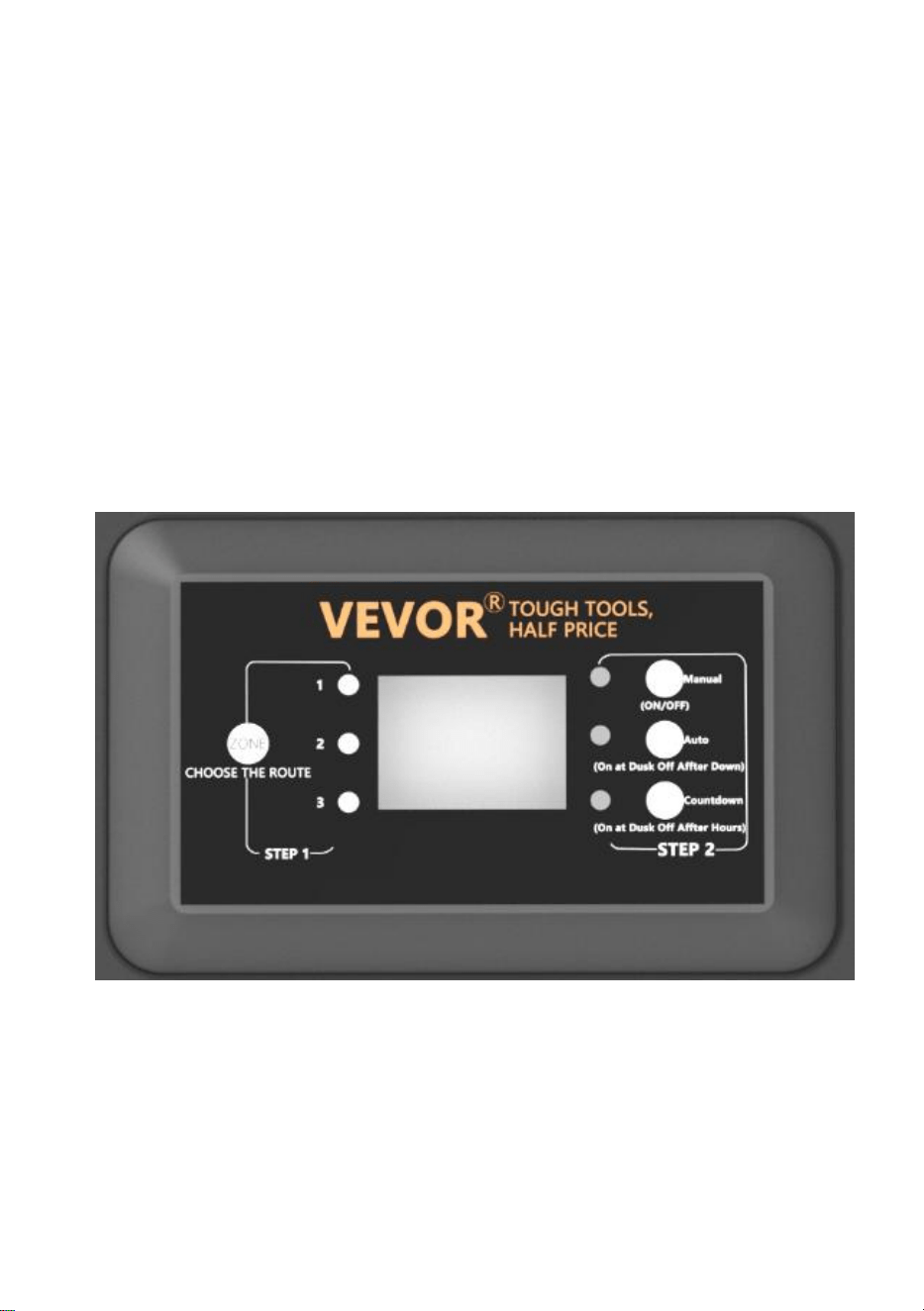
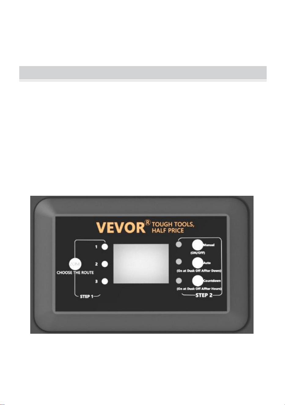
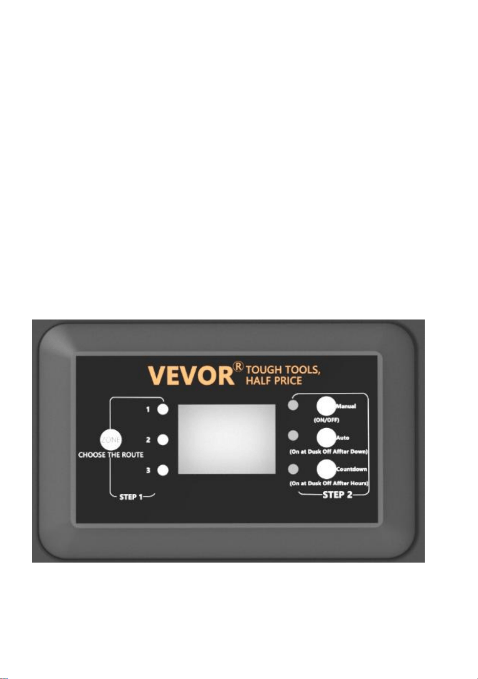
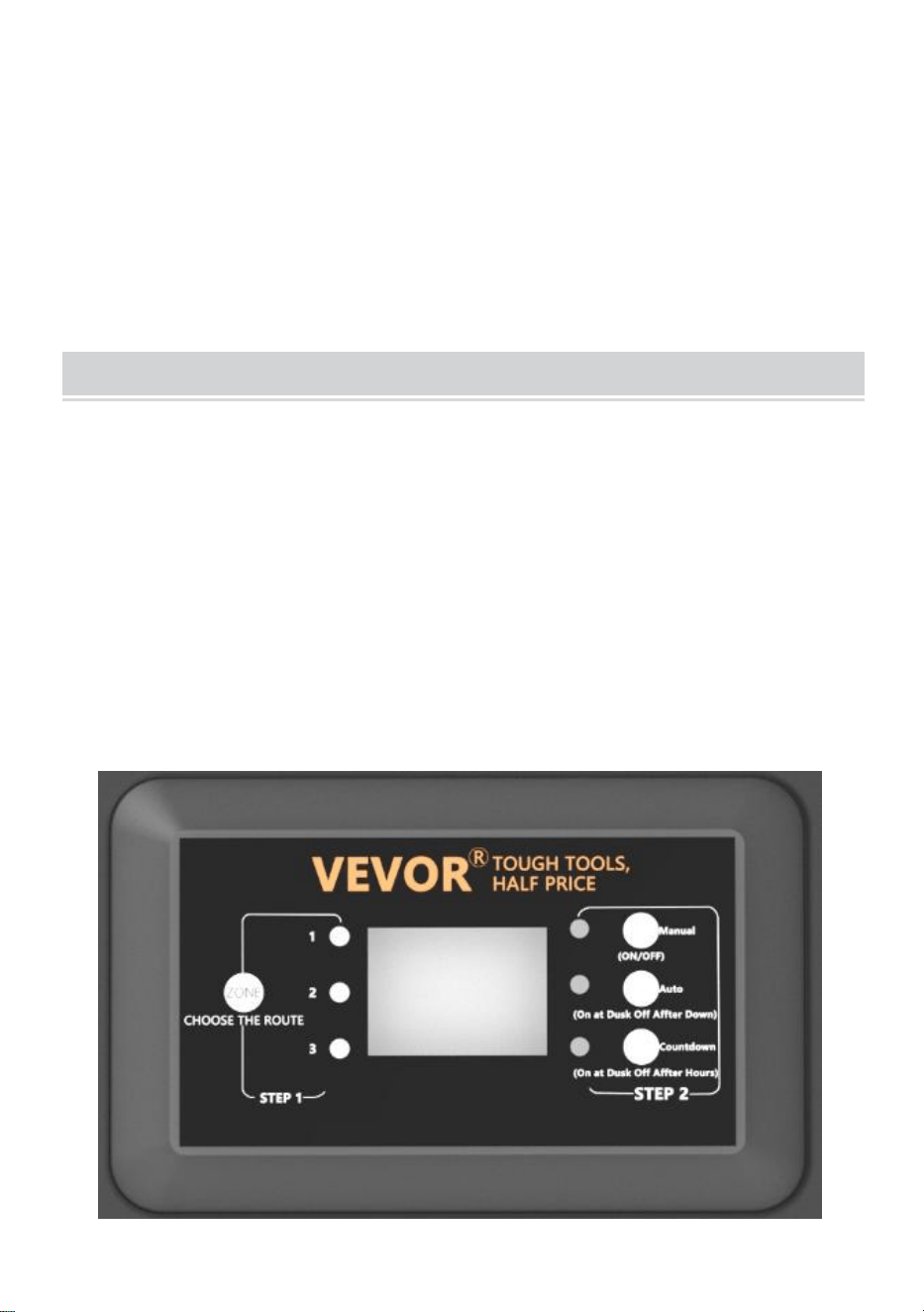
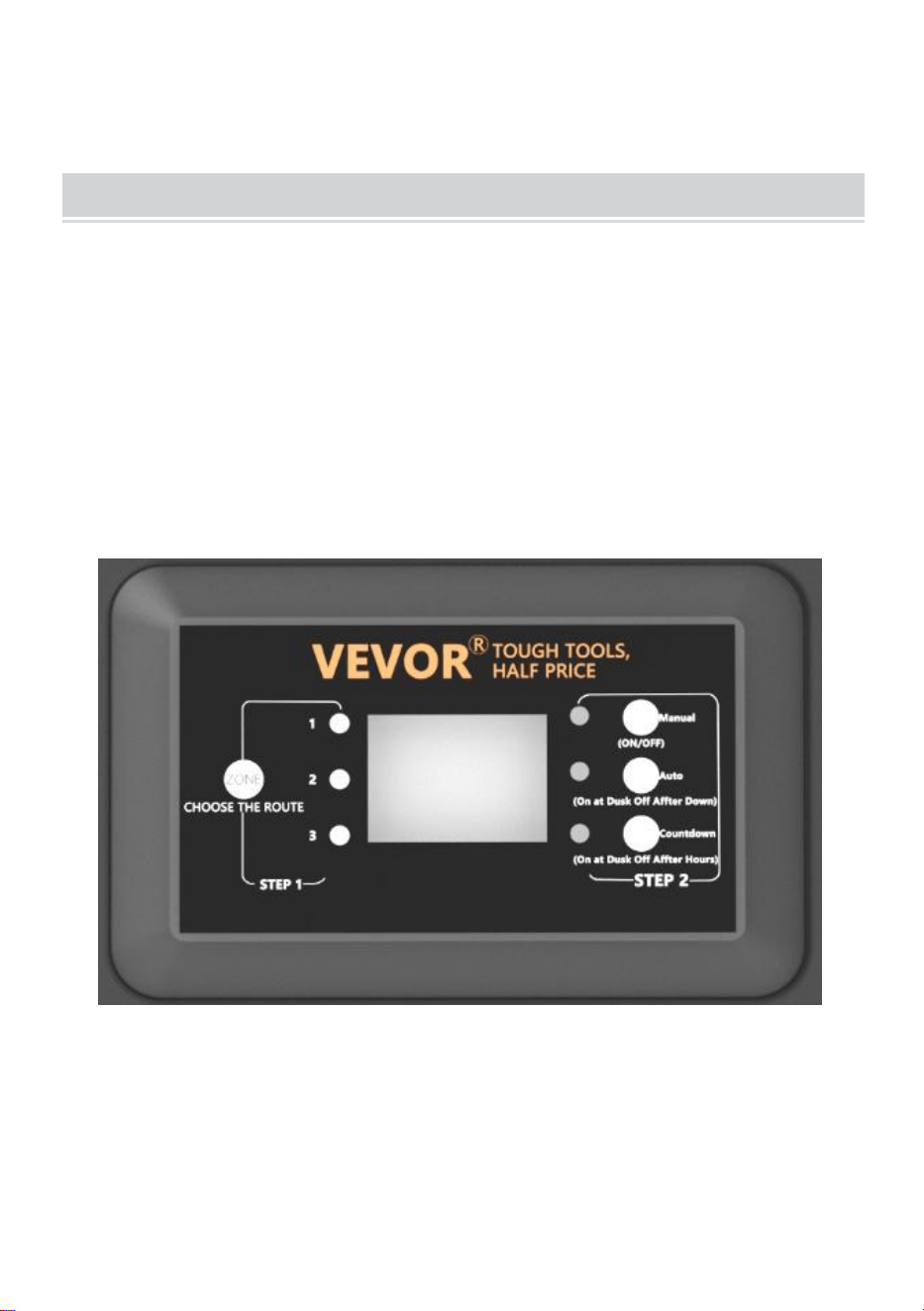
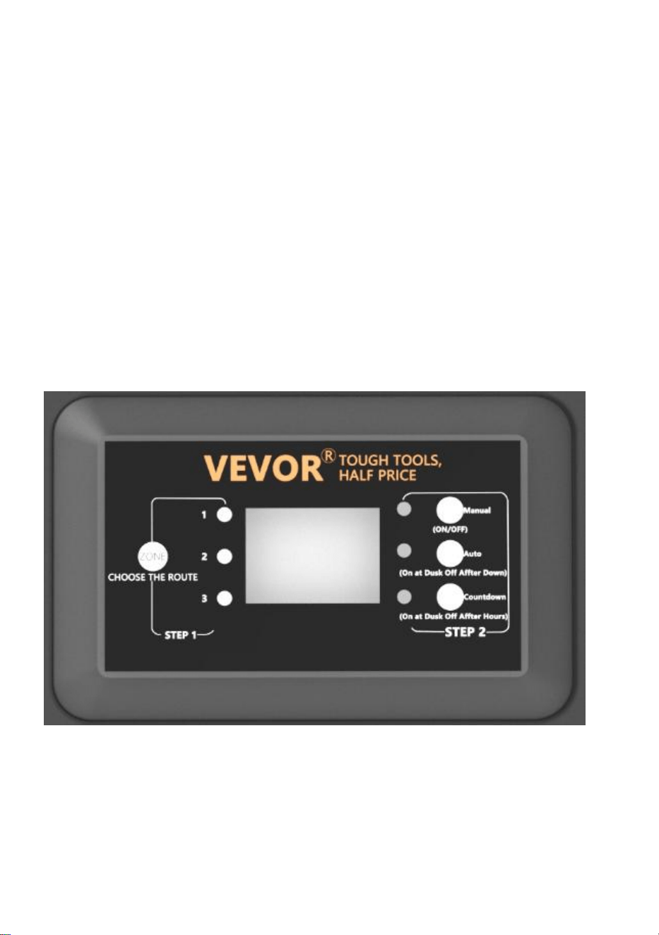
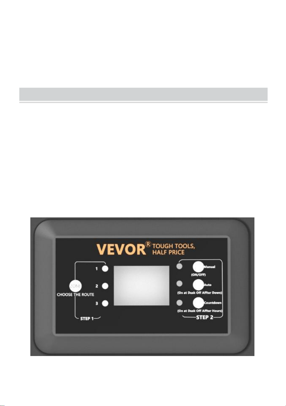
OPERATION
1、Operating in Manual Mode
This setting allows you to immediately turn the lights on and turn them off
when you no longer need them
a ) STEP1 Press ZONE. Select the line that needs to be manually set (a
total of 3 lines). Each time you press ZONE, the indicator light will cycle on,
and the corresponding line indicator light will illuminate to indicate that the
line is selected.
b ) STEP2 Press MANUAL. The MANUAL mode is now activated
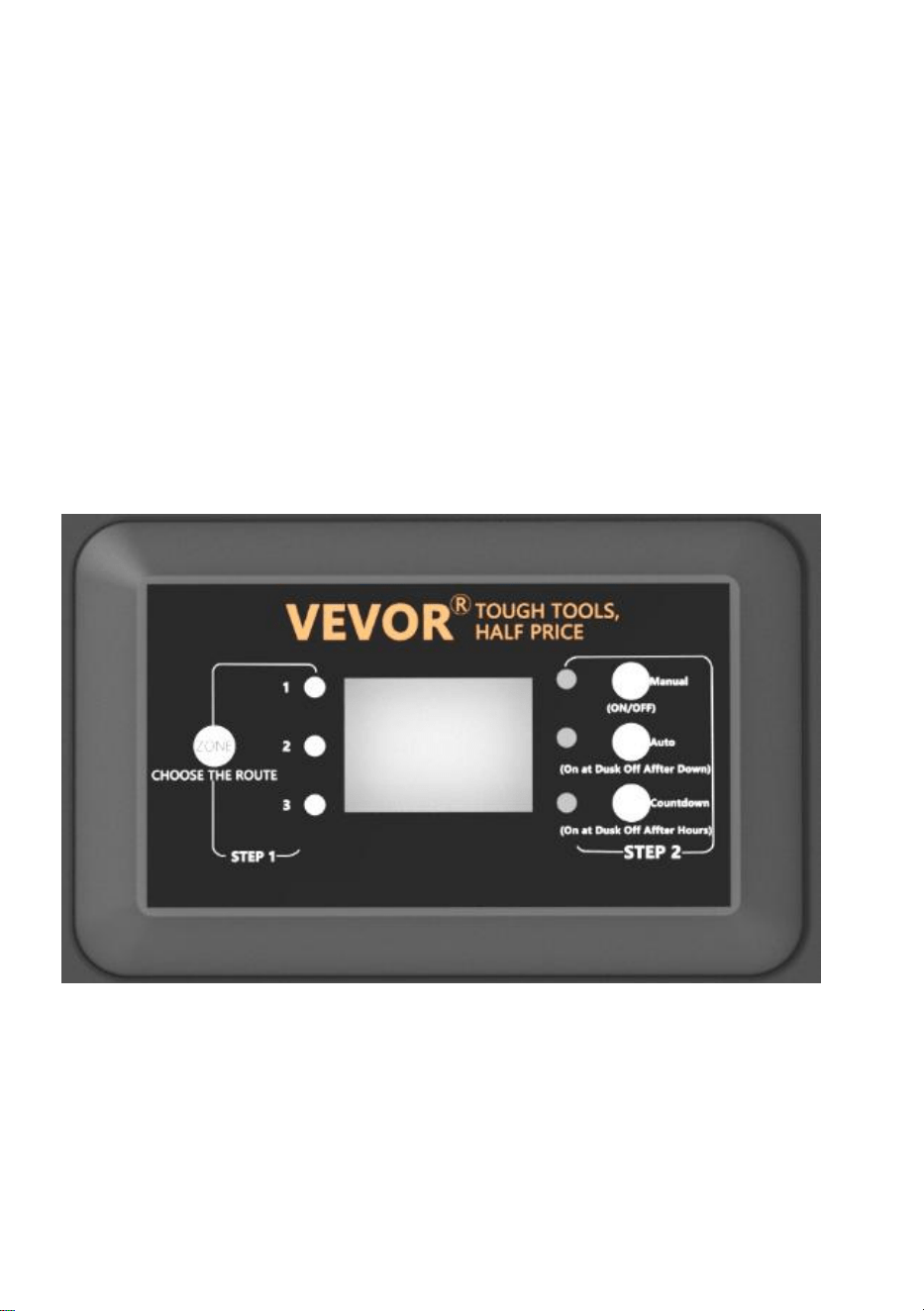
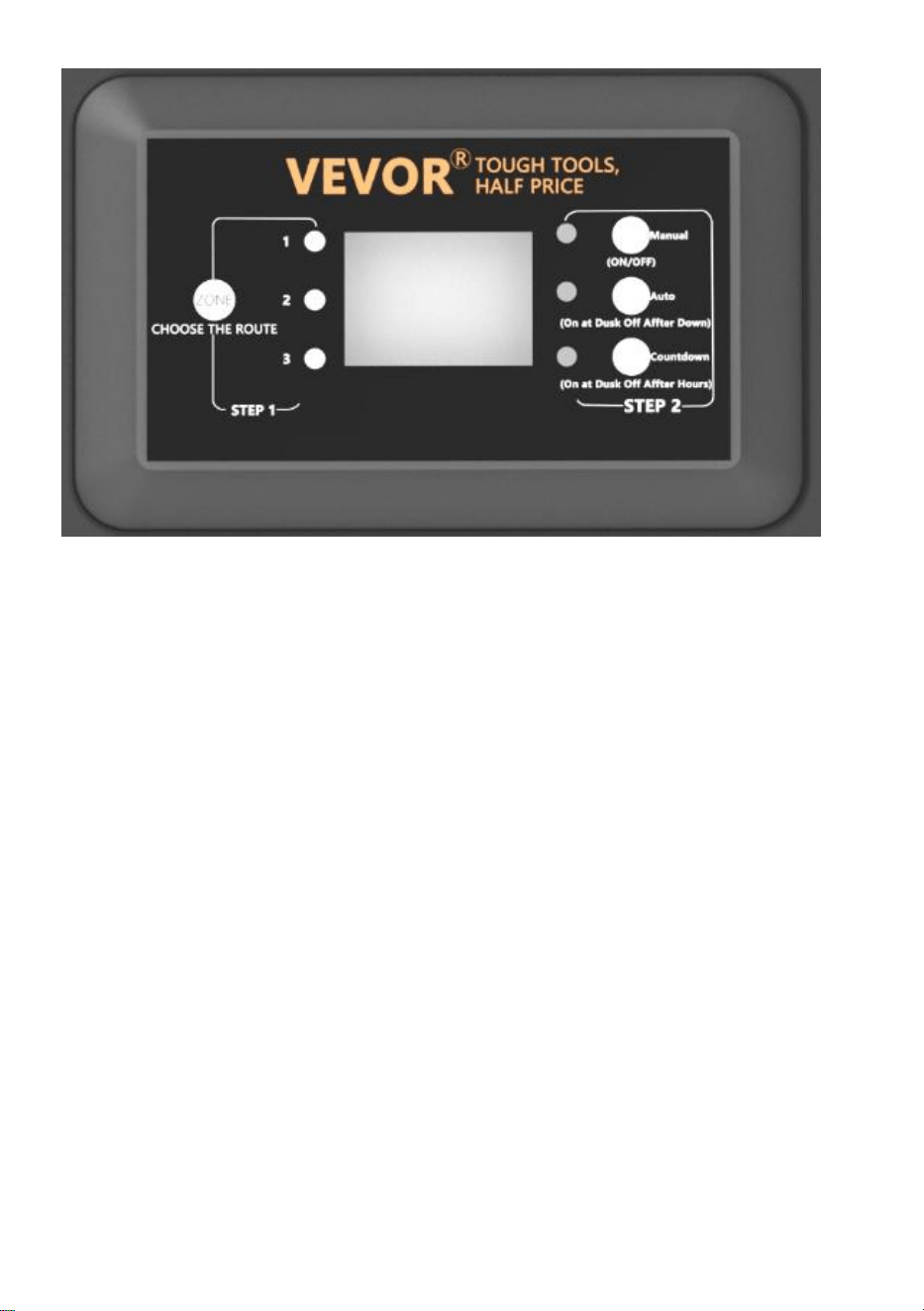
2、Setting PHOTOCELL AUTO ON / OFF
This setting allows the photocell to turn the lights on at dusk and off at
dawn
a ) STEP1 Press ZONE. Select the line that needs to be manually set (a
total of 3 lines). Each time you press ZONE, the indicator light will cycle on,
and the corresponding line indicator light will illuminate to indicate that the
line is selected.
b ) STEP2 Press AUTO until the AUTO LED indicator is lit. The
PHOTOCELL AUTO ON / OFF mode is now activated. The digit display
shows
AU.

3、Setting PHOTOCELL ON / TIME OFF
This setting allows the photocell to turn the lights on, and you set the time
they go off
a ) STEP1 Press ZONE. Select the line that needs to be manually set (a
total of 3 lines). Each time you press ZONE, the indicator light will cycle on,
and the corresponding line indicator light will illuminate to indicate that the
line is selected.
b ) STEP2 Press COUNTDOWN until the COUNTDOWN LED indicator is
lit. The COUNTDOWN mode is now activated.
c ) Press COUNTDOWN to select the time, with a time step of 1H and a
maximum setting of 12H.
NOTE:
When encountering a sudden power outage and power is restored, the
transformer will repeat the previous settings. If changes are needed, you
will need to manually reset the desired mode.

TROUBLESHOOTING
NOTE:
The buttons in the red box are three circuit protectors, corresponding to 1,
2, and 3 from bottom to top.
When the button protrudes, it represents the corresponding output
overload protection. After adjusting the load, press the corresponding
button to reset.
Made In China


Technique Certificat d'assistance et de garantie électronique
www.vevor.com/support
TRANSFORMATEUR
MANUEL D'UTILISATION
We continue to be committed to providing you tools with competitive price.
"Save Half", "Half Price" or any other similar expressions used by us only represent an
estimate of savings you might benefit from buying certain tools with us compared to the major
top brands and does not necessarily mean to cover all categories of tools offered by us. You
are kindly reminded to verify carefully when you are placing an order with us if you are
actually saving half in comparison with the top major brands.


MODÈLE : HPN-120GK2301 HPN-200GK2302 HPN-300GK2303
HPN-600GK2306
Have product questions? Need technical support? Please feel free to
contact us:
Technical Support and E-Warranty Certificate
www.vevor.com/support
NEED HELP? CONTACT US!
This is the original instruction, please read all manual instructions
carefully before operating. VEVOR reserves a clear interpretation of our
user manual. The appearance of the product shall be subject to the
product you received. Please forgive us that we won't inform you again if
there are any technology or software updates on our product.
TRANSFORMER

SAFETY INFORMATION
INFORMATIONS DE SÉCURITÉ IMPORTANTES POUR RÉDUIRE LES
RISQUES D'INCENDIE OU DE BLESSURE
Ne pas installer à moins de 10 pieds (3 m) d'une piscine, d'un spa ou d'une
fontaine.
À utiliser uniquement avec des systèmes d'éclairage paysager extérieurs
basse tension. Le bloc d'alimentation ne contient aucune pièce réparable.
NE PAS DEMONTER.
Ne pas immerger le transformateur.
Ne connectez pas deux ou plusieurs transformateurs en parallèle.
Ne pas utiliser avec un variateur.
Branchez le bloc d’alimentation directement sur une prise GFCI pour
endroit humide.
N'utilisez pas de rallonge.
AVERTISSEMENT :
Les changements ou modifications apportés à cet appareil non
expressément approuvés par la partie responsable de la conformité
pourraient annuler l'autorité des utilisateurs à utiliser l'équipement.
Note :
Cet équipement a été testé et jugé conforme aux limites d'un appareil
numérique de classe B, conformément à la partie 15 des règles de la FCC.
Ces limites sont conçues pour fournir une protection raisonnable contre les
interférences nuisibles dans une installation résidentielle. Cet équipement
génère, utilise et peut émettre de l'énergie radiofréquence et, s'il n'est pas
installé et utilisé conformément aux instructions, peut provoquer des
interférences nuisibles aux communications radio. Cependant, il n'y a
aucune garantie que des interférences ne se produiront pas dans une
installation particulière. Si cet équipement provoque des interférences
nuisibles à la réception radio ou télévision, ce qui peut être déterminé en
éteignant et en rallumant l'équipement, l'utilisateur est encouragé à
essayer de corriger les interférences en prenant une ou plusieurs des
mesures suivantes :
Réorienter ou déplacer l'antenne de réception. Augmenter la distance
entre l'équipement et le récepteur.
Connectez l’équipement à une prise sur un circuit différent de celui auquel
le récepteur est connecté.
Consultez le revendeur ou un radio expérimenté.
Pré-installation
AVERTISSEMENT :
Utilisez uniquement des câbles basse tension homologués CSA ou UL. Le
non-respect de ces instructions peut entraîner un risque d'incendie ou de
décharge électrique. L'utilisation d'un câble de grande taille garantit un
rendement lumineux maximal.
TECHNICAL PARAMETER
Modèl
e
HPN-120GK23
01
HPN-200GK2
302
HPN-300GK2303
HPN-600GK2306
Saisir
120 VCA, 60
Hz ,
1,14 A
120 VCA, 60
Hz ,
1,8 A
120 VCA, 60 Hz ,
2,68 A
120 VCA, 60 Hz ,
5,45 A
sortir
12 VCA / 10 A
(MAX)
12 VCA / 16,7
A (MAX)
12 VCA/ 25 A~ 14
VCA/21,4 A (MAX)
12 VCA/ 50 A~ 14 VA
C/42,8 A (MAX)
Pouvoi
r
120 W
200 W
300 W
600 W
Remarque : le transformateur dispose de trois ensembles de sorties,
chaque ensemble de puissance représentant un tiers de la puissance
totale.
Par exemple, la puissance totale est de 120 W et chaque sortie ne peut
pas dépasser 40 W ; la puissance totale est de 200 W et chaque sortie ne
peut pas dépasser 66 W ; la puissance totale est de 300 W et chaque
sortie ne peut pas dépasser 100 W. La puissance totale est de 600 W et
chaque sortie ne peut pas dépasser 200 W.
OUTILS REQUIS
MATÉRIEL INCLUS
Partie
Description
Quantité
UN
Transformateur
1
B
Photocellule
1
C
Gabarit de montage
1
REMARQUE : le matériel n'est pas représenté à la taille réelle.
INSTALLATION
8、Préparation du câble
En faisant attention lors de la séparation de NE PAS exposer le fil de cuivre,
retirez l'isolant du fil de paysage de 1/2 po des deux fils et torsadez les
extrémités.
9、Connexion du câble au transformateur
Posez le transformateur sur une surface plane et stable et insérez
l'extrémité dénudée d'un fil sous la plaque de serrage de la borne « COM ».
Répétez cette procédure pour la plaque de serrage « 12 V » ou « 14 V ».
10、REMARQUE : Tirez doucement sur le fil paysager pour vérifier si
la connexion est solide.
11、Placement de vos luminaires et acheminement des câbles
Disposez vos luminaires (non inclus) à l'endroit où vous souhaitez les
placer. Assurez-vous qu'ils ne dépassent pas la puissance nominale du
transformateur. Acheminez le câble basse tension jusqu'aux luminaires ;
s'il y a du câble supplémentaire, enroulez-le après le dernier luminaire.
AVERTISSEMENT : Risque d'incendie
Assurez-vous de laisser un minimum de 10 pieds (3 m) de fil entre le bloc
d’alimentation et le premier luminaire.
12、Fixation de vos luminaires
Allumez le transformateur. Fixez vos luminaires au câble à l'aide des
connecteurs de câble comme indiqué. Placez un connecteur de chaque
côté du câble, puis appuyez ensemble pour verrouiller. Les broches
perceront le câble pour établir le contact et vos luminaires devraient
s'allumer. Allumez le transformateur. Fixez vos luminaires au câble à l'aide
des connecteurs de câble comme indiqué. Appuyez fermement sur le
connecteur sur le câble jusqu'à ce que les broches percent l'isolation du
câble. Le luminaire devrait
s'allumer.
13、Montage du transformateur
Pour le montage direct sur une surface murale, utilisez les vis fournies
comme illustré, adaptées au montage à une distance de 1 à 1,5 m (39 à 59
po) du sol. Lors de l'installation des vis, l'espacement entre les . Accrochez
le transformateur (A) aux
vis.
14、Montage de la cellule photoélectrique
Montez le support de la cellule photoélectrique (B) sur un mur ou une autre
surface solide. Enclenchez le capteur dans le support. Acheminez ou
enroulez le fil excédentaire pour le protéger des tondeuses à gazon, des
coupe-bordures, etc.
Évitez de pointer le capteur vers des sources de lumière nocturne telles
que des fenêtres, des lampes de porche et des

lampadaires.
Placer le capteur dans des zones recevant moins de soleil au crépuscule
(côté est)
(de la maison, derrière des arbres et des buissons, sous une terrasse) fera
en sorte que le transformateur s'allume plus tôt dans la soirée. Le montage
de la cellule photoélectrique dans des endroits plus lumineux fera en sorte
que le transformateur s'allume lorsqu'il fait plus sombre dehors.
L'emplacement, la position et l'orientation de la cellule photoélectrique
peuvent être ajustés jusqu'à ce que le transformateur s'allume au niveau
de luminosité souhaité.
Si les fils de la cellule photoélectrique sont coupés ou cassés, la cellule
photoélectrique peut être remplacée. Dévissez le couvercle du connecteur
de la cellule photoélectrique du transformateur et retirez le connecteur à
deux broches de la prise correspondante.
La pièce de rechange est insérée dans la douille et le capuchon est revissé
sur la douille pour assurer une connexion étanche.
Notez que le connecteur bi-broches est polarisé et ne peut être inséré
dans la prise que dans un seul sens.
Une cellule photoélectrique de remplacement est disponible en magasin.
7、 Protéger ou cacher le câble
Une fois que tous les luminaires sont en place et que vous êtes satisfait de
leur
emplacements, le câble peut être recouvert de paillis ou enterré jusqu'à

6 po (15 cm) de profondeur. Laissez environ 12 po (30 cm) de câble après
le
dernier match.
AVERTISSEMENT : Risque d'incendie
N'enroulez pas le câble autour du transformateur. La puissance totale des
ampoules ne doit pas dépasser la puissance maximale du
transformateur.
OPERATION
1、 Fonctionnement en mode manuel
Ce paramètre vous permet d'allumer immédiatement les lumières et de les
éteindre lorsque vous n'en avez plus besoin
a ) ÉTAPE 1 Appuyez sur ZONE . Sélectionnez la ligne qui doit être réglée
manuellement (un total de 3 lignes). Chaque fois que vous appuyez sur
ZONE, le voyant lumineux s'allume et le voyant lumineux de la ligne
correspondante s'allume pour indiquer que la ligne est sélectionnée.
b) ÉTAPE 2 Appuyez sur MANUEL . Le mode MANUEL est maintenant
activé
2、Réglage de la fonction MARCHE/ARRÊT AUTOMATIQUE DE LA
PHOTOCELLULE
Ce réglage permet à la cellule photoélectrique d'allumer les lumières au
crépuscule et de les éteindre à l'aube
a ) ÉTAPE 1 Appuyez sur ZONE. Sélectionnez la ligne qui doit être réglée
manuellement (un total de 3 lignes). Chaque fois que vous appuyez sur
ZONE, le voyant lumineux s'allume et le voyant lumineux de la ligne
correspondante s'allume pour indiquer que la ligne est sélectionnée.
b ) ÉTAPE 2 Appuyez sur AUTO jusqu'à ce que le voyant AUTO s'allume.
Le mode AUTO ON / OFF de la PHOTOCELLULE est maintenant activé.
L'affichage numérique indique
AU.
3、Réglage de la MARCHE/ARRÊT de la PHOTOCELLULE
Ce paramètre permet à la cellule photoélectrique d'allumer les lumières et
vous définissez l'heure à laquelle elles s'éteignent.
a ) ÉTAPE 1 Appuyez sur ZONE. Sélectionnez la ligne qui doit être réglée
manuellement (un total de 3 lignes). Chaque fois que vous appuyez sur
ZONE, le voyant lumineux s'allume et le voyant lumineux de la ligne
correspondante s'allume pour indiquer que la ligne est sélectionnée.
b ) ÉTAPE 2 Appuyez sur COMPTE À REBOURS jusqu'à ce que le voyant
LED COMPTE À REBOURS s'allume. Le mode COMPTE À REBOURS
est maintenant activé.
c) Appuyez sur COMPTE À REBOURS pour sélectionner l'heure, avec un
pas de temps de 1H et un réglage maximum de 12H.
NOTE:
En cas de coupure de courant soudaine et de rétablissement du courant, le
transformateur répète les réglages précédents. Si des modifications sont
nécessaires, vous devrez réinitialiser manuellement le mode souhaité.
TROUBLESHOOTING
NOTE:
Les boutons dans la boîte rouge sont trois protecteurs de circuit,

correspondant à 1, 2 et 3 de bas en haut.
Lorsque le bouton dépasse, il représente la protection de surcharge de
sortie correspondante. Après avoir réglé la charge, appuyez sur le bouton
correspondant pour réinitialiser.
Fabriqué en Chine


Technisch Support und E-Garantie-Zertifikat www.vevor.com/support
TRANSFORMATOR
BEDIENUNGSANLEITUNG
We continue to be committed to providing you tools with competitive price.
"Save Half", "Half Price" or any other similar expressions used by us only represent an
estimate of savings you might benefit from buying certain tools with us compared to the major
top brands and does not necessarily mean to cover all categories of tools offered by us. You
are kindly reminded to verify carefully when you are placing an order with us if you are
actually saving half in comparison with the top major brands.


MODELL: HPN-120GK2301 HPN-200GK2302 HPN-300GK2303
HPN-600GK2306
Have product questions? Need technical support? Please feel free to
contact us:
Technical Support and E-Warranty Certificate
www.vevor.com/support
NEED HELP? CONTACT US!
This is the original instruction, please read all manual instructions
carefully before operating. VEVOR reserves a clear interpretation of our
user manual. The appearance of the product shall be subject to the
product you received. Please forgive us that we won't inform you again if
there are any technology or software updates on our product.
TRANSFORMER

SAFETY INFORMATION
WICHTIGE SICHERHEITSINFORMATIONEN ZUR REDUZIERUNG DES
BRAND- ODER VERLETZUNGSRISIKOS
Nicht in einem Umkreis von 3 m (10 Fuß) um ein Schwimmbecken, Spa
oder einen Springbrunnen installieren.
Nur zur Verwendung mit Niederspannungs-Außenbeleuchtungssystemen.
Im Inneren des Netzteils befinden sich keine zu wartenden Teile.
NICHT ZERLEGEN.
Tauchen Sie den Transformator nicht unter.
Schließen Sie nicht zwei oder mehr Transformatoren parallel an.
Nicht mit einem Dimmer verwenden.
Stecken Sie das Netzteil direkt in eine GFCI-Steckdose für feuchte
Bereiche.
Verwenden Sie kein Verlängerungskabel.
WARNUNG:
Durch Änderungen oder Modifikationen an diesem Gerät, die nicht
ausdrücklich von der für die Konformität verantwortlichen Partei genehmigt
wurden, kann die Berechtigung des Benutzers zum Betrieb des Geräts
erlöschen.
Notiz :
Dieses Gerät wurde getestet und entspricht den Grenzwerten für digitale
Geräte der Klasse B gemäß Teil 15 der FCC-Bestimmungen. Diese
Grenzwerte sollen einen angemessenen Schutz gegen schädliche
Störungen bei der Installation in Wohngebieten bieten. Dieses Gerät
erzeugt und verwendet Hochfrequenzenergie und kann diese ausstrahlen.
Wenn es nicht gemäß den Anweisungen installiert und verwendet wird,
kann es zu Störungen des Funkverkehrs kommen. Es gibt jedoch keine
Garantie dafür, dass bei einer bestimmten Installation keine Störungen
auftreten. Wenn dieses Gerät den Radio- oder Fernsehempfang stört (was
durch Ein- und Ausschalten des Geräts festgestellt werden kann), wird
dem Benutzer empfohlen, die Störungen durch eine oder mehrere der
folgenden Maßnahmen zu beheben:

Richten Sie die Empfangsantenne neu aus oder verlegen Sie sie.
Vergrößern Sie den Abstand zwischen Gerät und Empfänger.
Schließen Sie das Gerät an eine Steckdose an, die zu einem anderen
Stromkreis gehört als der Empfänger.
Wenden Sie sich an Ihren Händler oder einen erfahrenen Radiomoderator.
Vorinstallation
WARNUNG:
Verwenden Sie nur Niederspannungskabel mit CSA- oder UL-Zulassung.
Wenn Sie kein Kabel mit einer Stärke von mindestens 16 verwenden oder
es nicht gemäß dieser Anleitung installieren, besteht Brand- oder
Stromschlaggefahr. Die Verwendung eines dicken Kabels gewährleistet
maximale Lichtleistung.
TECHNICAL PARAMETER
Model
l
HPN-120GK23
01
HPN-200GK2
302
HPN-300GK2303
HPN-600GK2306
Eingan
g
120 V
Wechselstrom,
60 Hz ,
1,14 A
120 V
Wechselstrom
, 60 Hz ,
1,8 A
120 V
Wechselstrom, 60
Hz ,
2,68 A
120 V Wechselstrom,
60 Hz ,
5,45 A
Ausga
be
12 V
Wechselstrom
/10 A (MAX)
12 V
Wechselstrom
/16,7 A (MAX)
12 V Wechselstrom/
25 A – 14 V
Wechselstrom/21,4
A (MAX.)
12 V Wechselstrom/ 50
A~ 14 V
Wechselstrom/42,8 A
(MAX)
Leistu
ng
120 Watt
200 Watt
300 Watt
600 Watt
Hinweis: Der Transformator verfügt über drei Ausgangssätze, wobei
jeder Leistungssatz ein Drittel der Gesamtleistung ausmacht.
Beispiel: Die Gesamtleistung beträgt 120 W und jeder Ausgang kann 40

W nicht überschreiten; die Gesamtleistung beträgt 200 W und jeder
Ausgang kann 66 W nicht überschreiten; die Gesamtleistung beträgt 300
W und jeder Ausgang kann 100 W nicht überschreiten. Die Gesamtleistung
beträgt 600 W und jeder Ausgang kann 200 W nicht überschreiten.
BENÖTIGTES WERKZEUG
HARDWARE INKLUSIVE
Teil
Beschreibung
Menge
A
Transformator
1
B
Fotozelle
1
C
Montageschablone
1
HINWEIS: Die Hardware ist nicht in Originalgröße dargestellt.
INSTALLATION
15、Vorbereiten des Kabels
Achten Sie beim Teilen darauf, dass der Kupferdraht NICHT freiliegt.
Entfernen Sie die Isolierung des Landschaftsdrahts 1,27 cm weit von
beiden Drähten und verdrillten Enden.
16、Anschließen des Kabels an den Transformator
Legen Sie den Transformator auf eine flache, stabile Oberfläche und
stecken Sie das abisolierte Ende eines Kabels unter die Klemmplatte
„COM“. Wiederholen Sie diesen Vorgang für die Klemmplatte „12V“ oder
„14V“.
17、HINWEIS: Ziehen Sie vorsichtig am Landschaftsdraht, um zu
prüfen, ob die Verbindung stabil ist.
18、Platzieren der Vorrichtungen und Verlegen des Kabels
Legen Sie Ihre Leuchten (nicht im Lieferumfang enthalten) dort aus, wo Sie
sie anbringen möchten. Achten Sie darauf, dass sie die Nennleistung des
Transformators nicht überschreiten. Verlegen Sie das
Niederspannungskabel zu den Leuchten. Wenn ein zusätzliches Kabel
vorhanden ist, wickeln Sie es nach der letzten Leuchte auf.
WARNUNG: Brandgefahr
Lassen Sie unbedingt einen Kabelabstand von mindestens 3 m zwischen
dem Netzteil und der ersten Vorrichtung ein.
19、Anbringen Ihrer Vorrichtungen
Schalten Sie den Transformator ein. Befestigen Sie Ihre Leuchten mit den
Kabelverbindern wie gezeigt am Kabel. Platzieren Sie auf jeder Seite des
Kabels einen Verbinder und drücken Sie ihn dann zusammen, um ihn zu
verriegeln. Die Zinken werden das Kabel durchstechen, um Kontakt
herzustellen, und Ihre Leuchten sollten aufleuchten. Schalten Sie den
Transformator ein. Befestigen Sie Ihre Leuchten mit den Kabelverbindern
wie gezeigt am Kabel. Drücken Sie den Verbinder fest auf das Kabel, bis
die Zinken die Kabelisolierung durchstechen. Die Leuchte sollte
aufleuchten.

20、Montage des Transformators
Zur direkten Befestigung an einer Wandoberfläche verwenden Sie die
mitgelieferten Schrauben wie abgebildet. Sie sind für eine Befestigung in
einer Höhe von 1 m bis 1,5 m über dem Boden geeignet. Achten Sie beim
Anbringen der Schrauben auf den Abstand zwischen den . Hängen Sie den
Transformator (A) an die
Schrauben.

21、Montage der Fotozelle
Montieren Sie die Halterung der Fotozelle (B) an einer Wand oder einer
anderen festen Oberfläche. Lassen Sie den Sensor in die Halterung
einrasten. Verlegen oder wickeln Sie das überschüssige Kabel auf, um es
vor Rasenmähern, Trimmern usw. zu schützen.
Vermeiden Sie es, den Sensor auf nächtliche Lichtquellen wie Fenster,
Verandalichter und Straßenlaternen zu
richten.

Platzieren Sie den Sensor in Bereichen, die in der Dämmerung weniger
Sonnenlicht erhalten (Ostseite
Wenn Sie die Fotozelle an einer helleren Stelle anbringen, schaltet sich der
Transformator ein, wenn es draußen dunkler geworden ist. Die Position
und Ausrichtung der Fotozelle können angepasst werden, bis der
Transformator bei der gewünschten Lichtstärke einschaltet.
Wenn die Kabel zur Fotozelle durchtrennt oder gebrochen sind, kann die
Fotozelle ausgetauscht werden. Schrauben Sie die Anschlussabdeckung
der Fotozelle vom Transformator ab und ziehen Sie den zweipoligen
Stecker aus der passenden Buchse.
Das Ersatzteil wird in die Fassung eingesetzt und die Kappe wieder auf die
Fassung geschraubt, um eine wasserdichte Verbindung herzustellen.
Beachten Sie, dass der Zweistiftstecker polarisiert ist und nur auf eine Art
in die Buchse eingesteckt werden kann.
Ersatz-Lichtschranke ist im Handel erhältlich.
7. Schützen oder Verstecken des Kabels
Sobald alle Vorrichtungen installiert sind und Sie mit deren
Standorte, das Kabel kann mit Mulch abgedeckt oder bis zu
15 cm tief. Lassen Sie nach dem
letztes Spiel.
WARNUNG: Brandgefahr
Wickeln Sie das Kabel nicht um den Transformator. Die Gesamtwattzahl
der Glühbirne darf die maximale Leistung des Transformators nicht
überschreiten.
OPERATION
1. Betrieb im manuellen Modus
Mit dieser Einstellung können Sie das Licht sofort einschalten und die
Lichter ausschalten, wenn Sie sie nicht mehr benötigen.
a) SCHRITT 1 Drücken Sie ZONE . Wählen Sie die Leitung aus, die
manuell eingestellt werden soll (insgesamt 3 Leitungen). Bei jedem
Drücken von ZONE leuchtet die Kontrollleuchte abwechselnd auf und die
entsprechende Leitungskontrollleuchte leuchtet auf, um anzuzeigen, dass
die Leitung ausgewählt ist.
b) SCHRITT 2 Drücken Sie MANUAL . Der MANUELLE Modus ist nun
aktiviert
2. Einstellen der automatischen Fotozelle ein/aus
Mit dieser Einstellung kann die Fotozelle das Licht bei Dämmerung ein-
und bei Tagesanbruch ausschalten.
a) SCHRITT 1 Drücken Sie ZONE. Wählen Sie die Leitung aus, die
manuell eingestellt werden muss (insgesamt 3 Leitungen). Bei jedem
Drücken von ZONE leuchtet die Kontrollleuchte abwechselnd auf und die
entsprechende Leitungskontrollleuchte leuchtet auf, um anzuzeigen, dass
die Leitung ausgewählt ist.
b) SCHRITT 2 Drücken Sie AUTO, bis die AUTO-LED-Anzeige leuchtet.
Der PHOTOCELL AUTO ON / OFF-Modus ist jetzt aktiviert. Die
Ziffernanzeige zeigt AU
an.

3. Einstellen von LICHTSCHRANKE EIN / ZEIT AUS
Mit dieser Einstellung können Sie die Lichtschranke einschalten und die
Zeit einstellen, zu der sie ausgehen.
a) SCHRITT 1 Drücken Sie ZONE. Wählen Sie die Leitung aus, die
manuell eingestellt werden muss (insgesamt 3 Leitungen). Bei jedem
Drücken von ZONE leuchtet die Kontrollleuchte abwechselnd auf und die
entsprechende Leitungskontrollleuchte leuchtet auf, um anzuzeigen, dass
die Leitung ausgewählt ist.
b) SCHRITT 2 Drücken Sie COUNTDOWN, bis die COUNTDOWN-LED
leuchtet. Der COUNTDOWN-Modus ist jetzt aktiviert.
c) Drücken Sie COUNTDOWN, um die Zeit mit einem Zeitschritt von 1
Stunde und einer Maximaleinstellung von 12 Stunden auszuwählen.
NOTIZ:
Bei einem plötzlichen Stromausfall und anschließender Wiederherstellung
der Stromversorgung wiederholt der Transformator die vorherigen
Einstellungen. Wenn Änderungen erforderlich sind, müssen Sie den
gewünschten Modus manuell zurücksetzen.
TROUBLESHOOTING
NOTIZ:
Die Tasten im roten Feld sind drei Sicherungsautomaten, die von unten
nach oben den Nummern 1, 2 und 3 entsprechen.
Wenn der Knopf hervorsteht, stellt er den entsprechenden
Ausgangsüberlastungsschutz dar. Drücken Sie nach dem Einstellen der
Last den entsprechenden Knopf zum Zurücksetzen.
In China hergestellt


Tecnico Supporto e certificato di garanzia elettronica www.vevor.com/support
TRASFORMATORE
MANUALE D'USO
We continue to be committed to providing you tools with competitive price.
"Save Half", "Half Price" or any other similar expressions used by us only represent an
estimate of savings you might benefit from buying certain tools with us compared to the major
top brands and does not necessarily mean to cover all categories of tools offered by us. You
are kindly reminded to verify carefully when you are placing an order with us if you are
actually saving half in comparison with the top major brands.


MODELLO: HPN-120GK2301 HPN-200GK2302 HPN-300GK2303
HPN-600GK2306
Have product questions? Need technical support? Please feel free to
contact us:
Technical Support and E-Warranty Certificate
www.vevor.com/support
NEED HELP? CONTACT US!
This is the original instruction, please read all manual instructions
carefully before operating. VEVOR reserves a clear interpretation of our
user manual. The appearance of the product shall be subject to the
product you received. Please forgive us that we won't inform you again if
there are any technology or software updates on our product.
TRANSFORMER

SAFETY INFORMATION
INFORMAZIONI IMPORTANTI SULLA SICUREZZA PER RIDURRE IL
RISCHIO DI INCENDI O LESIONI
Non installare a meno di 3 metri (10 piedi) da una piscina, spa o fontana.
Da utilizzare solo con sistemi di illuminazione paesaggistica esterna a
bassa tensione. Non ci sono parti riparabili all'interno dell'unità di
alimentazione.
NON SMONTARE.
Non immergere il trasformatore.
Non collegare due o più trasformatori in parallelo.
Non utilizzarlo con un dimmer.
Collegare l'alimentatore direttamente a una presa GFCI per ambienti
umidi.
Non utilizzare prolunghe.
AVVERTIMENTO :
Eventuali modifiche o alterazioni apportate a questa unità non
espressamente approvate dalla parte responsabile della conformità
potrebbero invalidare l'autorizzazione dell'utente a utilizzare
l'apparecchiatura.
Nota:
Questa apparecchiatura è stata testata e ritenuta conforme ai limiti per un
dispositivo digitale di Classe B, ai sensi della parte 15 delle Norme FCC.
Questi limiti sono concepiti per fornire una protezione ragionevole contro
interferenze dannose in un'installazione residenziale. Questa
apparecchiatura genera, utilizza e può irradiare energia a radiofrequenza e,
se non installata e utilizzata in conformità alle istruzioni, può causare
interferenze dannose alle comunicazioni radio. Tuttavia, non vi è alcuna
garanzia che non si verifichino interferenze in una particolare installazione.
Se questa apparecchiatura causa interferenze dannose alla ricezione
radiofonica o televisiva, il che può essere determinato accendendo e
spegnendo l'apparecchiatura, si consiglia all'utente di provare a correggere
l'interferenza con una o più delle seguenti misure:
Riorientare o riposizionare l'antenna ricevente. Aumentare la separazione
tra l'apparecchiatura e il ricevitore.
Collegare l'apparecchiatura a una presa di corrente appartenente a un
circuito diverso da quello a cui è collegato il ricevitore.
Rivolgersi al rivenditore o a un radioamatore esperto.
Pre-installazione
AVVERTIMENTO :
Utilizzare solo cavi a bassa tensione approvati da CSA o UL. Il mancato
utilizzo di cavi di calibro minimo 16 o la mancata installazione come
indicato in queste istruzioni può comportare un rischio di incendio o scossa
elettrica. L'utilizzo di un cavo di grandi dimensioni garantirà la massima
emissione di luce.
TECHNICAL PARAMETER
Model
lo
Modello
HPN-120GK23
01
Modello
HPN-200GK2
302
Modello
HPN-300GK2303
Modello
HPN-600GK2306
Ingres
so
120 V CA, 60
Hz ,
1.14A
120 V CA, 60
Hz ,
1.8A
120 V CA, 60 Hz ,
2.68A
120 V CA, 60 Hz ,
5.45A
produz
ione
12 V CA /10 A
(MAX)
12 V CA/16,7
A (MAX)
12 V CA/ 25 A ~ 14 V
CA / 21,4 A (MAX)
12VAC/ 50A~ 14VA
C/42,8A (MAX)
Energi
a
120 W
200 Watt
300 Watt
600 Watt
Nota: il trasformatore ha tre serie di uscite, ciascuna delle quali
rappresenta un terzo della potenza totale.
Ad esempio, la potenza totale è 120 W e ogni uscita non può superare i
40 W; la potenza totale è 200 W e ogni uscita non può superare i 66 W; la

potenza totale è 300 W e ogni uscita non può superare i 100 W. La
potenza totale è 600 W e ogni uscita non può superare i 200 W.
STRUMENTI NECESSARI
HARDWARE INCLUSO
Parte
Descrizione
Quantità
UN
Trasformatore
1
B
Fotocellula
1
C
Modello di montaggio
1
NOTA: l'hardware non è mostrato nelle dimensioni reali.
INSTALLATION
22、Preparazione del cavo
Facendo attenzione a NON esporre il filo di rame durante la divisione,
rimuovere l'isolamento del filo da giardino di 1/2 pollice da entrambi i fili e
attorcigliare le estremità.
23、Collegamento del cavo al trasformatore
Appoggiare il trasformatore su una superficie piana e stabile e inserire
l'estremità spelata di un filo sotto la piastra di serraggio del terminale
"COM". Ripetere questa procedura per la piastra di serraggio "12V" o
"14V".

24、NOTA: tirare delicatamente il filo del giardino per verificare se la
connessione è salda.
25、Posizionamento degli apparecchi e instradamento dei cavi
Disporre i dispositivi (non inclusi) dove si desidera posizionarli. Assicurarsi
che non superino la potenza nominale del trasformatore. Instradare il cavo
a bassa tensione verso i dispositivi; se c'è un cavo in più, avvolgerlo dopo
l'ultimo dispositivo.
ATTENZIONE: rischio di incendio
Assicurarsi di lasciare almeno 3 metri di cavo tra l'alimentatore e il primo
apparecchio.
26、Collegamento dei dispositivi
Accendere il trasformatore. Collegare i dispositivi al cavo utilizzando i
connettori del cavo come mostrato. Posizionare un connettore su ciascun
lato del cavo, quindi premere insieme per bloccare. I rebbi perforeranno il
cavo per stabilire il contatto e i dispositivi dovrebbero accendersi.
Accendere il trasformatore. Collegare i dispositivi al cavo utilizzando i
connettori del cavo come mostrato. Premere il connettore saldamente sul
cavo finché i rebbi non perforeranno l'isolamento del cavo. Il dispositivo
dovrebbe
accendersi.
27、Montaggio del trasformatore
Per il montaggio diretto su una superficie a parete, utilizzare le viti incluse
come mostrato, adatte per il montaggio entro 39 in. - 59 in. (1 m - 1,5 m)

dal terreno. Quando si installano le viti, la spaziatura tra . Appendere il
trasformatore (A) sulle
viti.
28、Montaggio della fotocellula
Montare la staffa della fotocellula (B) su una parete o su un'altra superficie
solida. Agganciare il sensore alla staffa. Instradare o avvolgere il filo in
eccesso per proteggerlo da tosaerba, decespugliatori, ecc.
Evitare di puntare il sensore verso fonti di luce notturna come finestre, luci
del portico e
lampioni.
Posizionare il sensore in aree che ricevono meno luce solare al tramonto
(lato est
della casa, dietro alberi e cespugli, sotto un ponte) il trasformatore si
accenderà prima la sera. Montando la fotocellula in luoghi più luminosi il
trasformatore si accenderà quando sarà diventato più buio. La posizione,
l'orientamento e la posizione della fotocellula possono essere regolati
finché il trasformatore non si accende al livello di luce desiderato.
Se i fili della fotocellula sono tagliati o rotti, la fotocellula può essere
sostituita. Svitare il coperchio del connettore della fotocellula dal
trasformatore ed estrarre il connettore bi-pin dalla presa di accoppiamento.
Il pezzo di ricambio viene inserito nella presa e il tappo viene riavvitato
sulla presa per garantire una connessione impermeabile.
Si noti che il connettore bipolare è polarizzato e può essere inserito nella
presa in un solo modo.
La fotocellula sostitutiva è disponibile in negozio.
7. Proteggere o nascondere il cavo
Una volta che tutti gli elementi sono a posto e sei soddisfatto del loro
posizioni, il cavo può essere coperto con pacciame o interrato fino a
6 pollici (15 cm) di profondità. Lasciare circa 12 pollici (30 cm) di cavo dopo
il
ultima partita.
ATTENZIONE: rischio di incendio
Non avvolgere il cavo attorno al trasformatore. La potenza totale della
lampadina non deve superare la potenza massima del
trasformatore.
OPERATION
1、 Funzionamento in modalità manuale
Questa impostazione ti consente di accendere immediatamente le luci e di
spegnerle quando non ne hai più bisogno
a) STEP1 Premere ZONE . Selezionare la linea che deve essere
impostata manualmente (un totale di 3 linee). Ogni volta che si preme
ZONE, la spia luminosa si accenderà ciclicamente e la spia luminosa della
linea corrispondente si illuminerà per indicare che la linea è selezionata.
b) STEP2 Premere MANUALE . La modalità MANUALE è ora attivata
2、Impostazione FOTOCELLULA AUTO ON / OFF
Questa impostazione consente alla fotocellula di accendere le luci al
tramonto e spegnerle all'alba
a) STEP1 Premere ZONE. Selezionare la linea che deve essere impostata
manualmente (un totale di 3 linee). Ogni volta che si preme ZONE, la spia
luminosa si accenderà ciclicamente e la spia luminosa della linea
corrispondente si illuminerà per indicare che la linea è selezionata.
b) STEP2 Premere AUTO finché non si accende l'indicatore LED AUTO. La
modalità FOTOCELLULA AUTO ON / OFF è ora attivata. Il display digitale
mostra
AU.

3、Impostazione FOTOCELLULA ON / TEMPO OFF
Questa impostazione consente alla fotocellula di accendere le luci e di
impostare l'ora in cui si spengono
a) STEP1 Premere ZONE. Selezionare la linea che deve essere impostata
manualmente (un totale di 3 linee). Ogni volta che si preme ZONE, la spia
luminosa si accenderà ciclicamente e la spia luminosa della linea
corrispondente si illuminerà per indicare che la linea è selezionata.
b) STEP2 Premere COUNTDOWN finché l'indicatore LED COUNTDOWN
non si accende. La modalità COUNTDOWN è ora attivata.
c) Premere COUNTDOWN per selezionare l'ora, con un intervallo di tempo
di 1 ora e un'impostazione massima di 12 ore.
NOTA:
Quando si verifica un'improvvisa interruzione di corrente e la corrente
viene ripristinata, il trasformatore ripeterà le impostazioni precedenti. Se
sono necessarie modifiche, sarà necessario reimpostare manualmente la
modalità desiderata.
TROUBLESHOOTING
NOTA:
I pulsanti nel riquadro rosso sono tre protettori di circuito, corrispondenti ai
numeri 1, 2 e 3 dal basso verso l'alto.
Quando il pulsante sporge, rappresenta la protezione da sovraccarico in
uscita corrispondente. Dopo aver regolato il carico, premere il pulsante
corrispondente per ripristinare.
Made in China


Técnico Soporte y certificado de garantía electrónica www.vevor.com/support
TRANSFORMADOR
MANUAL DE USUARIO
We continue to be committed to providing you tools with competitive price.
"Save Half", "Half Price" or any other similar expressions used by us only represent an
estimate of savings you might benefit from buying certain tools with us compared to the major
top brands and does not necessarily mean to cover all categories of tools offered by us. You
are kindly reminded to verify carefully when you are placing an order with us if you are
actually saving half in comparison with the top major brands.


MODELO: HPN-120GK2301 HPN-200GK2302 HPN-300GK2303
HPN-600GK2306
Have product questions? Need technical support? Please feel free to
contact us:
Technical Support and E-Warranty Certificate
www.vevor.com/support
NEED HELP? CONTACT US!
This is the original instruction, please read all manual instructions
carefully before operating. VEVOR reserves a clear interpretation of our
user manual. The appearance of the product shall be subject to the
product you received. Please forgive us that we won't inform you again if
there are any technology or software updates on our product.
TRANSFORMER

SAFETY INFORMATION
INFORMACIÓN DE SEGURIDAD IMPORTANTE PARA REDUCIR EL
RIESGO DE INCENDIO O LESIONES
No lo instale a menos de 10 pies (3 m) de una piscina, spa o fuente.
Para uso exclusivo con sistemas de iluminación de exteriores de bajo
voltaje. No hay piezas que requieran mantenimiento dentro de la fuente de
alimentación.
NO DESMONTAR.
No sumerja el transformador.
No conecte dos o más transformadores en paralelo.
No lo utilice con un regulador de intensidad.
Enchufe la fuente de alimentación directamente a un tomacorriente para
ubicación húmeda con GFCI.
No utilice un cable de extensión.
ADVERTENCIA :
Los cambios o modificaciones a esta unidad no aprobados expresamente
por la parte responsable del cumplimiento podrían anular la autoridad de
los usuarios para operar el equipo.
Nota :
Este equipo ha sido probado y se ha determinado que cumple con los
límites establecidos para dispositivos digitales de Clase B, de conformidad
con la parte 15 de las Normas de la FCC. Estos límites están diseñados
para proporcionar una protección razonable contra interferencias
perjudiciales en una instalación residencial. Este equipo genera, utiliza y
puede irradiar energía de radiofrecuencia y, si no se instala y utiliza de
acuerdo con las instrucciones, puede causar interferencias perjudiciales
en las comunicaciones por radio. Sin embargo, no existe garantía de que
no se produzcan interferencias en una instalación en particular. Si este
equipo causa interferencias perjudiciales en la recepción de radio o
televisión, lo que se puede determinar encendiendo y apagando el equipo,
se recomienda al usuario que intente corregir la interferencia mediante una
o más de las siguientes medidas:
Reorientar o reubicar la antena receptora. Aumentar la separación entre el
equipo y el receptor.
Conecte el equipo a una toma de corriente de un circuito diferente a aquel
al que está conectado el receptor.
Consulte con el distribuidor o con un radio experimentado.
Preinstalación
ADVERTENCIA :
Utilice únicamente cables de bajo voltaje aprobados por CSA o UL. Si no
se utiliza un cable de calibre mínimo de 16 o no se instala como se indica
en estas instrucciones, puede producirse un riesgo de incendio o descarga
eléctrica. El uso de un cable de gran calibre garantizará la máxima salida
de luz.
TECHNICAL PARAMETER
Model
o
HPN-120GK23
01
HPN-200GK2
302
HPN-300GK2303
HPN-600GK2306
Aporte
120 V CA, 60
Hz ,
1.14A
120 V CA, 60
Hz ,
1.8A
120 V CA, 60 Hz ,
2,68A
120 V CA, 60 Hz ,
5,45 A
produc
ción
12 V CA /10 A
(MÁXIMO)
12 V CA/16,7
A (MÁXIMO)
12 V CA/ 25 A ~ 14 V
CA/21,4 A
(MÁXIMO)
12 V CA/ 50 A ~ 14 VA
C/42,8 A (MÁXIMO)
Fuerza
120 vatios
200 vatios
300 vatios
600 W
Nota: El transformador tiene tres conjuntos de salidas, y cada
conjunto de potencia representa un tercio de la potencia total.
Por ejemplo, la potencia total es de 120 W y cada salida no puede
superar los 40 W; la potencia total es de 200 W y cada salida no puede
superar los 66 W; la potencia total es de 300 W y cada salida no puede
superar los 100 W. La potencia total es de 600 W y cada salida no puede
superar los 200 W.
HERRAMIENTAS NECESARIAS
HARDWARE INCLUIDO
Parte
Descripción
Cantidad
A
Transformador
1
B
Célula fotoeléctrica
1
do
Plantilla de montaje
1
NOTA: El hardware no se muestra en su tamaño real.

INSTALLATION
29、Preparando el cable
Tenga cuidado al dividir de NO exponer el cable de cobre, retire el
aislamiento del cable de jardinería 1/2 pulgada de ambos cables y tuerza
los extremos.
30、Conexión del cable al transformador
Coloque el transformador sobre una superficie plana y estable e inserte el
extremo pelado de un cable debajo de la placa de sujeción del terminal
“COM”. Repita este procedimiento para la placa de sujeción “12V” o “14V”.

31、NOTA: Tire suavemente del cable del paisaje para verificar si la
conexión es fuerte.
32、Colocación de los accesorios y tendido del cable
Coloca las luminarias (no incluidas) en el lugar donde quieras colocarlas.
Asegúrate de que no excedan la capacidad nominal del transformador.
Enruta el cable de bajo voltaje hacia las luminarias; si hay cable adicional,
enróllalo después de la última luminaria.
ADVERTENCIA: Riesgo de incendio
Asegúrese de dejar un mínimo de 10 pies (3 m) de cable entre el paquete
de alimentación y el primer dispositivo.
33、Fijación de los accesorios

Encienda el transformador. Conecte las luminarias al cable utilizando los
conectores de cable como se muestra. Coloque un conector en cada lado
del cable y luego presiónelos para trabarlos. Las puntas perforarán el
cable para hacer contacto y las luminarias deberían encenderse. Encienda
el transformador. Conecte las luminarias al cable utilizando los conectores
de cable como se muestra. Presione el conector firmemente sobre el cable
hasta que las puntas perforen el aislamiento del cable. La luminaria
debería
encenderse.
34、Montaje del transformador
Para montarlo directamente en una superficie de pared, use los tornillos
incluidos como se muestra, adecuados para el montaje a una distancia de
entre 39 y 59 pulgadas (1 m y 1,5 m) del suelo. Al instalar los tornillos, el
espacio entre los . Cuelgue el transformador (A) en los
tornillos.
35、Montaje de la fotocélula
Coloque el soporte de la fotocélula (B) en una pared u otra superficie
sólida. Coloque el sensor en el soporte. Enrolle o pase el cable sobrante
para protegerlo de las cortadoras de césped, las podadoras, etc.
Evite apuntar el sensor hacia fuentes de luz nocturna, como ventanas,
luces de porches y luces de la
calle.
Colocar el sensor en áreas que reciben menos luz solar al anochecer (lado
este)
En lugares como el interior de la casa, detrás de árboles y arbustos,
debajo de una terraza, el transformador se activará más temprano por la
noche. Si se instala la fotocélula en lugares más iluminados, el
transformador se activará cuando oscurezca. La ubicación, la posición y la
orientación de la fotocélula se pueden ajustar hasta que el transformador
se active con el nivel de luz deseado.
Si los cables de la fotocélula están cortados o rotos, se puede reemplazar
la fotocélula. Desatornille la tapa del conector de la fotocélula del
transformador y extraiga el conector de dos clavijas del zócalo
correspondiente.
La pieza de repuesto se inserta en el zócalo y la tapa se enrosca
nuevamente en el zócalo para proporcionar una conexión hermética.
Tenga en cuenta que el conector de dos pines está polarizado y solo se
puede insertar en el zócalo de una manera.
La fotocélula de repuesto está disponible en la tienda.
7、 Cómo proteger u ocultar el cable
Una vez que todos los accesorios estén en su lugar y esté satisfecho con
ellos,
En algunos lugares, el cable puede cubrirse con mantillo o enterrarse
hasta
6 pulgadas (15 cm) de profundidad. Deje aproximadamente 12 pulgadas
(30 cm) de cable después de la
último encuentro.
ADVERTENCIA: Riesgo de incendio
No enrolle el cable alrededor del transformador. La potencia total de las
bombillas no debe superar la potencia máxima del
transformador.
OPERATION
1、 Operación en modo manual
Esta configuración le permite encender las luces inmediatamente y
apagarlas cuando ya no las necesite.
a ) PASO 1 Pulse ZONE . Seleccione la línea que se debe configurar
manualmente (un total de 3 líneas). Cada vez que pulse ZONE, la luz
indicadora se encenderá y la luz indicadora de la línea correspondiente se
iluminará para indicar que la línea está seleccionada.
b ) PASO 2 Pulse MANUAL . El modo MANUAL está ahora activado.

2、Configuración del encendido y apagado automático de la
fotocélula
Esta configuración permite que la fotocélula encienda las luces al
anochecer y las apague al amanecer.
a ) PASO 1 Presione ZONE. Seleccione la línea que necesita configurarse
manualmente (un total de 3 líneas). Cada vez que presione ZONE, la luz
indicadora se encenderá y la luz indicadora de la línea correspondiente se
iluminará para indicar que la línea está seleccionada.
b ) PASO 2 Pulse AUTO hasta que se encienda el indicador LED AUTO. El
modo de ENCENDIDO/APAGADO AUTOMÁTICO DE LA FOTOCÉLULA
está ahora activado. La pantalla de dígitos muestra
AU.
3、Configuración de ENCENDIDO/APAGADO DE LA FOTOCÉLULA
Esta configuración permite que la fotocélula encienda las luces y usted
establece el tiempo en que se apagan.
a ) PASO 1 Presione ZONE. Seleccione la línea que necesita configurarse
manualmente (un total de 3 líneas). Cada vez que presione ZONE, la luz
indicadora se encenderá y la luz indicadora de la línea correspondiente se
iluminará para indicar que la línea está seleccionada.
b ) PASO 2 Pulse COUNTDOWN hasta que se encienda el indicador LED
de CUENTA REGRESIVA. El modo CUENTA REGRESIVA ahora está
activado.
c ) Pulse COUNTDOWN para seleccionar el tiempo, con un paso de
tiempo de 1H y un ajuste máximo de 12H.
NOTA:
Cuando se produce un corte de energía repentino y se restablece la
energía, el transformador repetirá la configuración anterior. Si es necesario
realizar cambios, deberá restablecer manualmente el modo deseado.
TROUBLESHOOTING
NOTA:
Los botones en el cuadro rojo son tres protectores de circuito,
correspondientes a 1, 2 y 3 de abajo a arriba.

Cuando el botón sobresale, representa la protección de sobrecarga de
salida correspondiente. Después de ajustar la carga, presione el botón
correspondiente para restablecer.
Hecho en china


Techniczny Wsparcie i certyfikat gwarancji elektronicznej www.vevor.com/support
TRANSFORMATOR
INSTRUKCJA OBSŁUGI
We continue to be committed to providing you tools with competitive price.
"Save Half", "Half Price" or any other similar expressions used by us only represent an
estimate of savings you might benefit from buying certain tools with us compared to the major
top brands and does not necessarily mean to cover all categories of tools offered by us. You
are kindly reminded to verify carefully when you are placing an order with us if you are
actually saving half in comparison with the top major brands.


MODELU: HPN-120GK2301 HPN-200GK2302 HPN-300GK2303
HPN-600GK2306
Have product questions? Need technical support? Please feel free to
contact us:
Technical Support and E-Warranty Certificate
www.vevor.com/support
NEED HELP? CONTACT US!
This is the original instruction, please read all manual instructions
carefully before operating. VEVOR reserves a clear interpretation of our
user manual. The appearance of the product shall be subject to the
product you received. Please forgive us that we won't inform you again if
there are any technology or software updates on our product.
TRANSFORMER

SAFETY INFORMATION
WAŻNE INFORMACJE DOTYCZĄCE BEZPIECZEŃSTWA, MNIEJSZE
RYZYKO POŻARU LUB OBRAŻEŃ
Nie montować w odległości mniejszej niż 10 stóp (3 m) od basenu, spa lub
fontanny.
Do użytku wyłącznie z niskonapięciowymi systemami oświetlenia
zewnętrznego. Wewnątrz jednostki zasilającej nie ma żadnych części
nadających się do serwisowania.
NIE ROZMONTOWYWAĆ.
Nie zanurzać transformatora.
Nie należy łączyć dwóch lub więcej transformatorów równolegle.
Nie należy używać go ze ściemniaczem.
Podłącz zasilacz bezpośrednio do gniazdka GFCI w miejscu narażonym
na wilgoć.
Nie używaj przedłużacza.
OSTRZEŻENIE:
Zmiany lub modyfikacje tego urządzenia, które nie zostały wyraźnie
zatwierdzone przez stronę odpowiedzialną za zgodność, mogą
spowodować unieważnienie prawa użytkownika do korzystania z
urządzenia.
Notatka :
To urządzenie zostało przetestowane i uznane za zgodne z limitami dla
urządzeń cyfrowych klasy B, zgodnie z częścią 15 przepisów FCC. Limity
te mają na celu zapewnienie rozsądnej ochrony przed szkodliwymi
zakłóceniami w instalacjach mieszkalnych. To urządzenie generuje,
wykorzystuje i może emitować energię o częstotliwości radiowej i jeśli nie
zostanie zainstalowane i używane zgodnie z instrukcją, może powodować
szkodliwe zakłócenia w komunikacji radiowej. Nie ma jednak gwarancji, że
zakłócenia nie wystąpią w konkretnej instalacji. Jeśli to urządzenie
powoduje szkodliwe zakłócenia w odbiorze radia lub telewizji, co można
ustalić, wyłączając i włączając urządzenie, zachęca się użytkownika do
podjęcia próby skorygowania zakłóceń za pomocą jednego lub kilku z
następujących środków:
Zmień orientację lub lokalizację anteny odbiorczej. Zwiększ odległość
między urządzeniem a odbiornikiem.
Podłącz urządzenie do gniazdka w innym obwodzie niż ten, do którego
podłączony jest odbiornik.
Skonsultuj się ze sprzedawcą lub doświadczonym radioodbiornikiem.
Przed instalacją
OSTRZEŻENIE:
Używaj wyłącznie kabli niskonapięciowych zatwierdzonych przez CSA lub
UL. Nieużywanie kabla o minimalnej grubości 16 lub nieinstalowanie go
zgodnie z niniejszą instrukcją może skutkować ryzykiem pożaru lub
porażenia prądem. Użycie dużego kabla zapewni maksymalną moc
światła.
TECHNICAL PARAMETER
Model
HPN-120GK23
01
HPN-200GK2
302
HPN-300GK2303
HPN-600GK2306
Wejści
e
120 V AC, 60
Hz ,
1,14A
120 V AC, 60
Hz ,
1,8 A
120 V AC, 60 Hz ,
2,68A
120 V AC, 60 Hz ,
5,45A
wyjści
e
12VAC /10A
(maks.)
12VAC /16,7A
(MAKS.)
12VAC/ 25A~
14VAC / 21,4A
(MAKS.)
12VAC/ 50A~ 14VA
C/42,8A (MAKS.)
Moc
120 W
200 W
300 W
600 W
Uwaga: Transformator ma trzy zestawy wyjść, każdy zestaw mocy
odpowiada za jedną trzecią całkowitej mocy.
Na przykład, całkowita moc wynosi 120 W, a każde wyjście nie może
przekraczać 40 W; całkowita moc wynosi 200 W, a każde wyjście nie może
przekraczać 66 W; całkowita moc wynosi 300 W, a każde wyjście nie może
przekraczać 100 W. Całkowita moc wynosi 600 W, a każde wyjście nie
może przekraczać 200 W.
WYMAGANE NARZĘDZIA
SPRZĘT W ZESTAWIE
Część
Opis
Ilość
A
Transformator
1
B
Fotokomórka
1
C
Szablon montażowy
1
UWAGA: Sprzęt nie jest pokazany w rzeczywistych rozmiarach.

INSTALLATION
36、Przygotowanie kabla
Zachowując ostrożność podczas rozdzielania, aby NIE odsłonić przewodu
miedzianego, usuń izolację przewodu ogrodowego na długości 1/2 cala z
obu przewodów i skręć końce.
37、Podłączanie kabla do transformatora
Połóż transformator na płaskiej, stabilnej powierzchni i włóż odizolowany
koniec jednego przewodu pod płytkę zaciskową zacisku „COM”. Powtórz
tę procedurę dla płytki zaciskowej „12V” lub „14V”.
38、UWAGA: Delikatnie pociągnij za przewód uziemiający, aby
sprawdzić, czy połączenie jest mocne.
39、Ustawianie opraw i prowadzenie kabli
Rozłóż oprawy (nie są dołączone) w miejscu, w którym chcesz je umieścić.
Upewnij się, że nie przekraczają one znamionowego napięcia
transformatora. Poprowadź kabel niskiego napięcia do opraw; jeśli jest
dodatkowy kabel, zwiń go za ostatnią oprawą.
OSTRZEŻENIE: Ryzyko pożaru
Należy pamiętać o pozostawieniu co najmniej 3 metrów (10 stóp)
przewodu między zasilaczem a pierwszym urządzeniem.
40、Mocowanie urządzeń
Włącz transformator. Podłącz oprawy do kabla za pomocą złączy
kablowych, jak pokazano. Umieść po jednym złączu po każdej stronie
kabla, a następnie dociśnij je, aby zablokować. Zęby przebiją kabel, aby
nawiązać kontakt, a oprawy powinny się zapalić. Włącz transformator.
Podłącz oprawy do kabla za pomocą złączy kablowych, jak pokazano.
Dociśnij złącze mocno do kabla, aż zęby przebiją izolację kabla. Oprawa
powinna się
zapalić.
41、Montaż transformatora
Aby zamontować bezpośrednio na powierzchni ściany, użyj dołączonych
śrub, jak pokazano, odpowiednich do montażu w odległości od 39 do 59
cali (1 m do 1,5 m) od podłoża. Podczas instalowania śrub odległość
między . Zawieś transformator (A) na
śrubach.
42、Montaż fotokomórki
Zamontuj uchwyt fotokomórki (B) na ścianie lub innej twardej powierzchni.
Wciśnij czujnik do uchwytu. Poprowadź lub zwiń nadmiar przewodu, aby
chronić go przed kosiarkami, trymerami itp.
Unikaj kierowania czujnika na źródła światła występujące w nocy, takie jak
okna, lampy na ganku i latarnie
uliczne.
Umieszczenie czujnika w miejscach, w których o zmierzchu dociera mniej
światła słonecznego (strona wschodnia)
domu, za drzewami i krzewami, pod tarasem) spowoduje, że transformator
włączy się wcześniej wieczorem. Zamontowanie fotokomórki w
jaśniejszych miejscach spowoduje, że transformator włączy się, gdy zrobi
się ciemniej. Położenie, pozycję i orientację fotokomórki można regulować,
aż transformator włączy się przy pożądanym poziomie światła.
Jeśli przewody do fotokomórki są przecięte lub uszkodzone, fotokomórkę
można wymienić. Odkręć pokrywę złącza fotokomórki od transformatora i
wyciągnij złącze dwupinowe z gniazda.
Część zamienną wkłada się do gniazda, a następnie nakręca się zaślepkę
na gniazdo, aby zapewnić szczelne połączenie.
Należy pamiętać, że złącze dwupinowe jest spolaryzowane i można je
włożyć do gniazda tylko w jeden sposób.
Zamienną fotokomórkę można nabyć w sklepie.
7. Ochrona lub ukrywanie kabla
Gdy wszystkie elementy wyposażenia są już na swoim miejscu i jesteś z
nich zadowolony,
lokalizacja, kabel może być przykryty ściółką lub zakopany do
6 cali (15 cm) głębokości. Pozostaw około 12 cali (30 cm) kabla po
ostatni mecz.
OSTRZEŻENIE: Ryzyko pożaru
Nie zwijaj kabla wokół transformatora. Całkowita moc żarówki nie może
przekraczać maksymalnej mocy
transformatora.
OPERATION
1. Praca w trybie ręcznym
To ustawienie umożliwia natychmiastowe włączenie oświetlenia i
wyłączenie go, gdy nie jest już potrzebne.
a) KROK 1 Naciśnij ZONE . Wybierz linię, którą chcesz ustawić ręcznie
(łącznie 3 linie). Za każdym razem, gdy naciśniesz ZONE, lampka
kontrolna będzie się cyklicznie zapalać, a odpowiednia lampka kontrolna
linii zaświeci się, aby wskazać, że linia została wybrana.
b) KROK 2 Naciśnij MANUAL . Tryb MANUAL jest teraz aktywowany.
2、Ustawianie automatycznego włączania/wyłączania fotokomórki
To ustawienie umożliwia fotokomórce włączanie świateł o zmierzchu i
wyłączanie o świcie
a) KROK 1 Naciśnij ZONE. Wybierz linię, którą należy ustawić ręcznie
(łącznie 3 linie). Za każdym razem, gdy naciśniesz ZONE, lampka
kontrolna będzie się cyklicznie włączać, a odpowiednia lampka kontrolna
linii zaświeci się, aby wskazać, że linia została wybrana.
b) KROK 2 Naciskaj przycisk AUTO, aż zaświeci się wskaźnik LED AUTO.
Tryb PHOTOCELL AUTO ON/OFF jest teraz aktywowany. Na
wyświetlaczu cyfrowym pojawi się
AU.

3、Ustawianie FOTOKOMÓRKI WŁĄCZONEJ/CZASOWEJ
To ustawienie pozwala fotokomórce włączać światła, a Ty ustawiasz czas,
po którym światła zostaną wyłączone.
a) KROK 1 Naciśnij ZONE. Wybierz linię, którą należy ustawić ręcznie
(łącznie 3 linie). Za każdym razem, gdy naciśniesz ZONE, lampka
kontrolna będzie się cyklicznie włączać, a odpowiednia lampka kontrolna
linii zaświeci się, aby wskazać, że linia została wybrana.
b) KROK 2 Naciskaj COUNTDOWN, aż zaświeci się wskaźnik LED
COUNTDOWN. Tryb COUNTDOWN jest teraz aktywowany.
c) Naciśnij przycisk COUNTDOWN, aby wybrać czas, z krokiem co 1
godzinę i maksymalnym ustawieniem 12 godzin.
NOTATKA:
W przypadku nagłej przerwy w dostawie prądu i przywrócenia zasilania
transformator powtórzy poprzednie ustawienia. Jeśli zmiany są konieczne,
należy ręcznie zresetować żądany tryb.

TROUBLESHOOTING
NOTATKA:
Przyciski w czerwonym polu to trzy zabezpieczenia obwodów,
odpowiadające numerom 1, 2 i 3 od dołu do góry.
Gdy przycisk wystaje, oznacza to odpowiednie zabezpieczenie
przeciążeniowe wyjścia. Po wyregulowaniu obciążenia naciśnij odpowiedni
przycisk, aby zresetować.
Wyprodukowano w Chinach


Technisch Ondersteuning en E-garantiecertificaat www.vevor.com/support
TRANSFORMATOR
GEBRUIKSAANWIJZING
We continue to be committed to providing you tools with competitive price.
"Save Half", "Half Price" or any other similar expressions used by us only represent an
estimate of savings you might benefit from buying certain tools with us compared to the major
top brands and does not necessarily mean to cover all categories of tools offered by us. You
are kindly reminded to verify carefully when you are placing an order with us if you are
actually saving half in comparison with the top major brands.

MODEL: HPN-120GK2301 HPN-200GK2302 HPN-300GK2303
HPN-600GK2306
Have product questions? Need technical support? Please feel free to
contact us:
Technical Support and E-Warranty Certificate
www.vevor.com/support
NEED HELP? CONTACT US!
This is the original instruction, please read all manual instructions
carefully before operating. VEVOR reserves a clear interpretation of our
user manual. The appearance of the product shall be subject to the
product you received. Please forgive us that we won't inform you again if
there are any technology or software updates on our product.
TRANSFORMER

SAFETY INFORMATION
BELANGRIJKE VEILIGHEIDSINFORMATIE OM HET RISICO OP
BRAND OF LETSEL TE VERMINDEREN
Niet installeren binnen een afstand van 3 meter van een zwembad, spa of
fontein.
Alleen voor gebruik met laagspanningsbuitenverlichtingssystemen. Er
bevinden zich geen onderdelen die gerepareerd kunnen worden in de
voedingseenheid.
NIET DEMONTEREN.
Dompel de transformator niet onder.
Sluit niet twee of meer transformatoren parallel aan.
Gebruik het niet met een dimmer.
Sluit de voeding rechtstreeks aan op een stopcontact met
aardlekschakelaar (GFCI) voor vochtige ruimtes.
Gebruik geen verlengsnoer.
WAARSCHUWING:
Wijzigingen of aanpassingen aan dit apparaat die niet uitdrukkelijk zijn
goedgekeurd door de partij die verantwoordelijk is voor de naleving,
kunnen de bevoegdheid van de gebruiker om het apparaat te bedienen
ongeldig maken.
Opmerking :
Deze apparatuur is getest en voldoet aan de limieten voor een digitaal
apparaat van klasse B, overeenkomstig deel 15 van de FCC-regels. Deze
limieten zijn ontworpen om redelijke bescherming te bieden tegen
schadelijke interferentie in een residentiële installatie. Deze apparatuur
genereert, gebruikt en kan radiofrequentie-energie uitstralen en kan, indien
niet geïnstalleerd en gebruikt in overeenstemming met de instructies,
schadelijke interferentie veroorzaken in radiocommunicatie. Er is echter
geen garantie dat er geen interferentie zal optreden in een bepaalde
installatie. Als deze apparatuur schadelijke interferentie veroorzaakt in
radio- of televisieontvangst, wat kan worden vastgesteld door de
apparatuur uit en aan te zetten, wordt de gebruiker aangemoedigd om te
proberen de interferentie te corrigeren door een of meer van de volgende
maatregelen:
Heroriënteer of verplaats de ontvangende antenne. Vergroot de afstand
tussen de apparatuur en de ontvanger.
Sluit het apparaat aan op een stopcontact van een ander circuit dan
waarop de ontvanger is aangesloten.
Raadpleeg de dealer of een ervaren radiotechnicus.
Voorinstallatie
WAARSCHUWING:
Gebruik alleen CSA- of UL-goedgekeurde laagspanningskabels. Als u
geen kabel van minimaal 16 gauge gebruikt of deze niet installeert zoals
aangegeven in deze instructies, kan dit leiden tot brandgevaar of een
elektrische schok. Als u een grote kabel gebruikt, is de lichtopbrengst
maximaal.
TECHNICAL PARAMETER
Model
HPN-120GK23
01
HPN-200GK2
302
HPN-300GK2303
HPN-600GK2306
Invoer
120VAC, 60Hz ,
1.14A
120VAC,
60Hz ,
1.8A
120VAC, 60Hz ,
2.68A
120VAC, 60Hz ,
5.45A
uitvoer
12VAC / 10A
(MAX)
12VAC /16,7A
(MAX)
12VAC/ 25A~
14VAC /21,4A (MAX)
12VAC/ 50A~ 14VA
spanning/42,8A (MAX)
Stroo
m
120 Watt
200 Watt
300 Watt
600 Watt
Let op: De transformator heeft drie sets uitgangen, waarbij elke
vermogensset een derde van het totale vermogen vertegenwoordigt.
Bijvoorbeeld, het totale vermogen is 120W, en elke uitgang kan niet meer

dan 40W zijn; het totale vermogen is 200W, en elke uitgang kan niet meer
dan 66W zijn; het totale vermogen is 300W, en elke uitgang kan niet meer
dan 100W zijn. Het totale vermogen is 600W, en elke uitgang kan niet
meer dan 200W zijn.
BENODIGDE GEREEDSCHAPPEN
INBEGREPEN HARDWARE
Deel
Beschrijving
Hoeveelheid
A
Transformator
1
B
Fotocel
1
C
Montage sjabloon
1
LET OP: De hardware wordt niet op ware grootte weergegeven.
INSTALLATION
43、De kabel voorbereiden
Wees voorzichtig bij het splitsen, zodat de koperdraad NIET bloot komt te
liggen. Verwijder de isolatie van de landschapsdraad 1,25 cm van beide
draden en draai de uiteinden in elkaar.
44、De kabel aansluiten op de transformator
Leg de transformator op een vlakke, stabiele ondergrond en steek het
gestripte uiteinde van één draad onder de klemplaat “COM”. Herhaal deze
procedure voor de klemplaat “12V” of “14V”.

45、OPMERKING: Trek voorzichtig aan de landschapsdraad om te
controleren of de verbinding sterk is.
46、Plaatsen van uw armaturen en routeren van de kabel
Leg uw fixtures (niet inbegrepen) neer waar u ze wilt plaatsen. Zorg ervoor
dat ze de capaciteit van de transformator niet overschrijden. Leid de
laagspanningskabel naar de fixtures; als er extra kabel is, rol deze dan op
na de laatste fixture.
WAARSCHUWING: Brandgevaar
Zorg ervoor dat er minimaal 3 meter draad tussen de voeding en het eerste
armatuur zit.
47、Uw armaturen bevestigen

Zet de transformator aan. Bevestig uw armaturen aan de kabel met behulp
van kabelconnectoren zoals afgebeeld. Plaats een connector aan elke
kant van de kabel en druk ze vervolgens samen om te vergrendelen. De
pinnen doorboren de kabel om contact te maken en uw armaturen zouden
moeten oplichten. Zet de transformator aan. Bevestig uw armaturen aan
de kabel met behulp van de kabelconnectoren zoals afgebeeld. Druk de
connector stevig op de kabel totdat de pinnen de kabelisolatie doorboren.
De armatuur zou moeten
oplichten.
48、De transformator monteren
Om direct aan een muuroppervlak te bevestigen, gebruikt u de
meegeleverde schroeven zoals afgebeeld, geschikt voor montage binnen

39 in. tot 59 in. (1 m tot 1,5 m) van de grond. Bij het installeren van de
schroeven, de afstand tussen de . Hang de transformator (A) aan de
schroeven.
49、Montage van de fotocel
Monteer de fotocel (B) beugel op een muur of ander stevig oppervlak. Klik
de sensor in de beugel. Leid of wikkel de overtollige draad om deze te
beschermen tegen grasmaaiers, trimmers, etc.
Richt de sensor niet op lichtbronnen in het donker, zoals ramen,

verandaverlichting en
straatverlichting.
Plaats de sensor op plekken waar minder zonlicht is tijdens de schemering
(oostkant)
van het huis, achter bomen en struiken, onder een terras) zal de
transformator eerder in de avond aan laten gaan. Als u de fotocel op een
lichtere locatie monteert, zal de transformator aangaan als het donkerder is
geworden. De locatie, positie en oriëntatie van de fotocel kunnen worden
aangepast totdat de transformator bij het gewenste lichtniveau aangaat.
Als de draden naar de fotocel zijn doorgesneden of gebroken, kan de
fotocel worden vervangen. Schroef de fotocelconnectorkap los van de
transformator en trek de bi-pinconnector uit de bijpassende socket.
Het vervangende onderdeel wordt in de fitting geplaatst en de dop wordt
weer op de fitting geschroefd, zodat er een waterdichte verbinding
ontstaat.
Houd er rekening mee dat de bi-pin connector gepolariseerd is en slechts
op één manier in de socket kan worden gestoken.
Vervangende fotocellen zijn verkrijgbaar in de winkel.
7. Beschermen of verbergen van de kabel
Zodra alle armaturen op hun plaats zitten en u tevreden bent met de
werking ervan,
Op bepaalde locaties kan de kabel worden bedekt met mulch of tot
maximaal 100 meter diep worden begraven.
6 inch (15 cm) diep. Laat ongeveer 12 inch (30 cm) kabel over na de
laatste wedstrijd.
WAARSCHUWING: Brandgevaar
Wikkel de kabel niet om de transformator. Het totale wattage van de lamp
mag het maximale vermogen van de transformator niet
overschrijden.
OPERATION
1、 Werken in handmatige modus
Met deze instelling kunt u de lampen direct aanzetten en de lampen weer
uitzetten als u ze niet meer nodig hebt.
a ) STAP 1 Druk op ZONE . Selecteer de lijn die handmatig moet worden
ingesteld (in totaal 3 lijnen). Elke keer dat u op ZONE drukt, gaat het
indicatielampje branden en gaat het bijbehorende lijnindicatielampje
branden om aan te geven dat de lijn is geselecteerd.
b ) STAP 2 Druk op MANUAL . De MANUAL-modus is nu geactiveerd
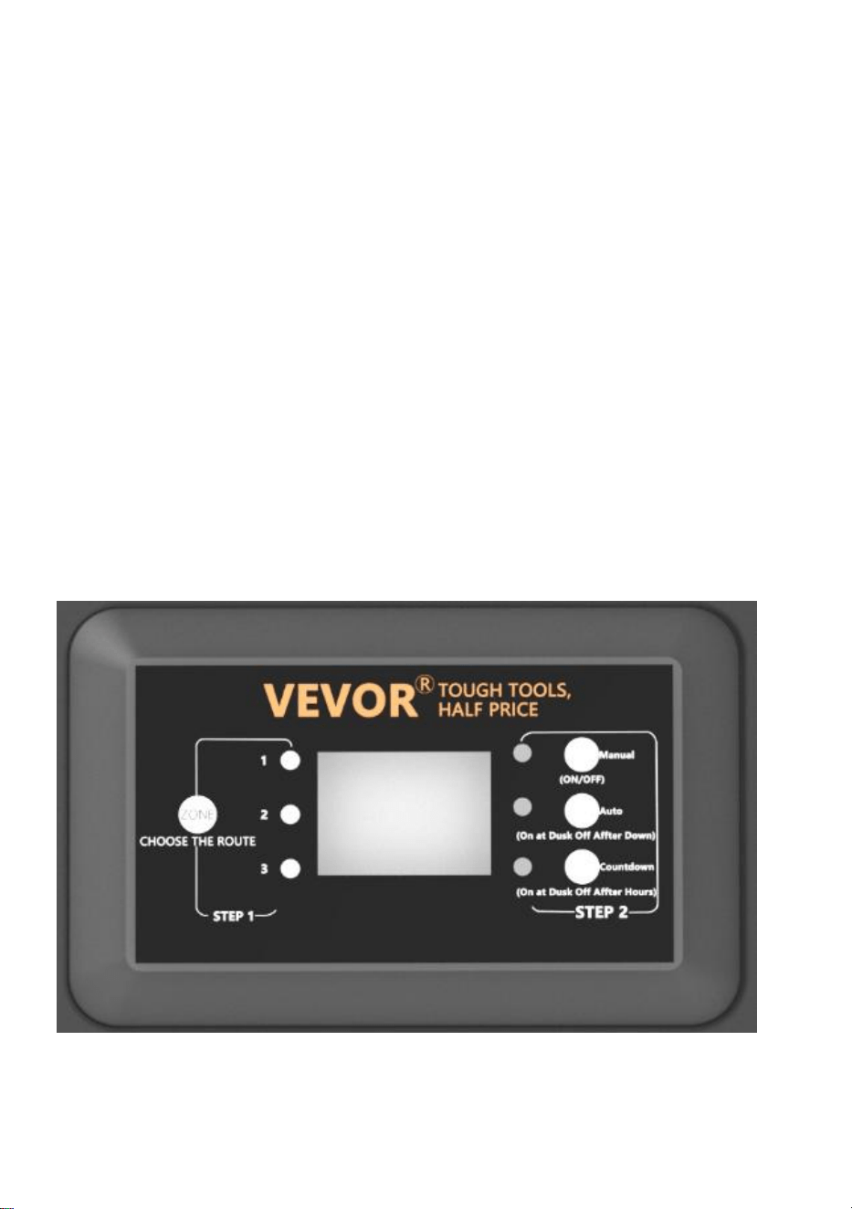
2. FOTOCEL AUTO AAN/UIT instellen
Met deze instelling kan de fotocel de verlichting bij schemering aanzetten
en bij zonsopgang uitschakelen.
a ) STAP 1 Druk op ZONE. Selecteer de lijn die handmatig moet worden
ingesteld (in totaal 3 lijnen). Elke keer dat u op ZONE drukt, gaat het
indicatielampje aan en gaat het bijbehorende lijnindicatielampje branden
om aan te geven dat de lijn is geselecteerd.
b ) STAP 2 Druk op AUTO totdat de AUTO LED-indicator brandt. De
PHOTOCELL AUTO AAN/UIT-modus is nu geactiveerd. Het cijferdisplay
toont
AU.

3. FOTOCEL AAN/TIJD UIT instellen
Met deze instelling kan de fotocel de lichten inschakelen en stelt u de tijd in
waarop ze uitgaan
a ) STAP 1 Druk op ZONE. Selecteer de lijn die handmatig moet worden
ingesteld (in totaal 3 lijnen). Elke keer dat u op ZONE drukt, gaat het
indicatielampje aan en gaat het bijbehorende lijnindicatielampje branden
om aan te geven dat de lijn is geselecteerd.
b ) STAP 2 Druk op COUNTDOWN totdat de COUNTDOWN LED-indicator
brandt. De COUNTDOWN-modus is nu geactiveerd.
c) Druk op COUNTDOWN om de tijd te selecteren, met een tijdstap van 1H
en een maximale instelling van 12H.
OPMERKING:
Wanneer er een plotselinge stroomstoring optreedt en de
stroomvoorziening wordt hersteld, herhaalt de transformator de vorige
instellingen. Als er wijzigingen nodig zijn, moet u de gewenste modus
handmatig opnieuw instellen.

TROUBLESHOOTING
OPMERKING:
De knoppen in het rode vakje zijn drie circuitbeschermers, die van onder
naar boven overeenkomen met 1, 2 en 3.
Wanneer de knop uitsteekt, vertegenwoordigt het de overeenkomstige
uitgangsoverbelastingsbeveiliging. Druk na het aanpassen van de
belasting op de overeenkomstige knop om te resetten.
Gemaakt in China


Teknisk Support och e-garanticertifikat www.vevor.com/support
TRANSFORMATOR
ANVÄNDARMANUAL
We continue to be committed to providing you tools with competitive price.
"Save Half", "Half Price" or any other similar expressions used by us only represent an
estimate of savings you might benefit from buying certain tools with us compared to the major
top brands and does not necessarily mean to cover all categories of tools offered by us. You
are kindly reminded to verify carefully when you are placing an order with us if you are
actually saving half in comparison with the top major brands.


MODELL: HPN-120GK2301 HPN-200GK2302 HPN-300GK2303
HPN-600GK2306
Have product questions? Need technical support? Please feel free to
contact us:
Technical Support and E-Warranty Certificate
www.vevor.com/support
NEED HELP? CONTACT US!
This is the original instruction, please read all manual instructions
carefully before operating. VEVOR reserves a clear interpretation of our
user manual. The appearance of the product shall be subject to the
product you received. Please forgive us that we won't inform you again if
there are any technology or software updates on our product.
TRANSFORMER

SAFETY INFORMATION
VIKTIG SÄKERHETSINFORMATION FÖR ATT MINSKA RISKEN FÖR
BRAND ELLER SKADA
Installera inte inom 10 fot (3 m) från en pool, spa eller fontän.
Endast för användning med lågspänningssystem för
utomhuslandskapsbelysning. Det finns inga delar som kan repareras inuti
strömförsörjningsenheten.
MONTERA INTE.
Sänk inte ner transformatorn.
Anslut inte två eller flera transformatorer parallellt.
Använd den inte med en dimmer.
Anslut strömförsörjningsenheten direkt till ett GFCI våtuttag.
Använd inte en förlängningssladd.
VARNING:
Ändringar eller modifieringar av denna enhet som inte uttryckligen
godkänts av den part som ansvarar för efterlevnaden kan ogiltigförklara
användarens behörighet att använda utrustningen.
Obs:
Denna utrustning har testats och befunnits överensstämma med gränserna
för en digital enhet av klass B, i enlighet med del 15 av FCC-reglerna.
Dessa gränser är utformade för att ge rimligt skydd mot skadliga störningar
i en bostadsinstallation. Denna utrustning genererar, använder och kan
utstråla radiofrekvensenergi och kan, om den inte installeras och används i
enlighet med instruktionerna, orsaka skadliga störningar på
radiokommunikation. Det finns dock ingen garanti för att störningar inte
kommer att inträffa i en viss installation. Om den här utrustningen orsakar
skadliga störningar på radio- eller tv-mottagning, vilket kan fastställas
genom att slå av och på utrustningen, uppmuntras användaren att försöka
korrigera störningen med en eller flera av följande åtgärder:
Rikta om eller flytta mottagningsantennen. Öka avståndet mellan
utrustningen och mottagaren.
Anslut utrustningen till ett uttag på en annan krets än den som mottagaren
är ansluten till.
Rådfråga återförsäljaren eller en erfaren radio.
Förinstallation
VARNING:
Använd endast CSA- eller UL-godkänd lågspänningskabel. Underlåtenhet
att använda minst 16 gauge kabel eller installera den enligt anvisningarna i
dessa instruktioner kan resultera i risk för brand eller elektriska stötar. Att
använda en stor kabel kommer att säkerställa maximal ljuseffekt.
TECHNICAL PARAMETER
Model
l
HPN-120GK23
01
HPN-200GK2
302
HPN-300GK2303
HPN-600GK2306
Input
120VAC, 60Hz ,
1,14A
120VAC,
60Hz ,
1,8A
120VAC, 60Hz ,
2,68A
120VAC, 60Hz ,
5,45A
produk
tion
12VAC /10A
(MAX)
12VAC /16,7A
(MAX)
12VAC/ 25A~
14VAC /21,4A (MAX)
12VAC/ 50A~ 14VA
C/42,8A (MAX)
Driva
120 W
200 W
300 W
600 W
Obs: Transformatorn har tre uppsättningar utgångar, varje
effektuppsättning står för en tredjedel av den totala effekten.
Till exempel är den totala effekten 120W, och varje utgång får inte
överstiga 40W; den totala effekten är 200W, och varje utgång får inte
överstiga 66W; den totala effekten är 300W, och varje utgång får inte
överstiga 100W. Den totala effekten är 600W, och varje utgång får inte
överstiga 200W.
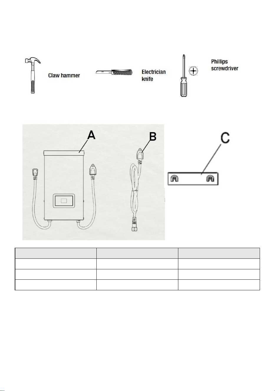
VERKTYG KRÄVS
HÅRDVARA INGÅR
Del
Beskrivning
Kvantitet
A
Transformator
1
B
Fotocell
1
C
Monteringsmall
1
OBS: Hårdvaran visas inte i verklig storlek.
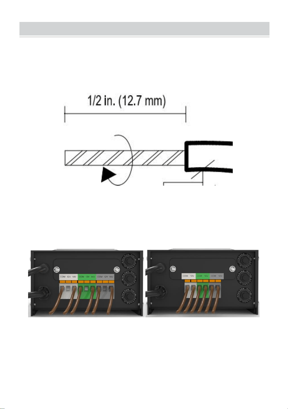
INSTALLATION
50、Förbereda kabeln
Var försiktig när du klyver så att du INTE exponerar koppartråden, ta bort
landskapstrådsisoleringen 1/2 tum från både kablar och tvinnade ändar.
51、Ansluta kabeln till transformatorn
Lägg transformatorn på en plan, stabil yta och för in den avskalade änden
av en ledning under plintklämplattan "COM". Upprepa denna procedur för
att klämma plattan "12V" eller "14V".
52、OBS: Dra försiktigt i den liggande kabeln för att kontrollera om
anslutningen är stark.
53、Placera dina fixturer och dra kabeln
Lägg dina armaturer (ingår ej) där du vill placera dem. Se till att de inte
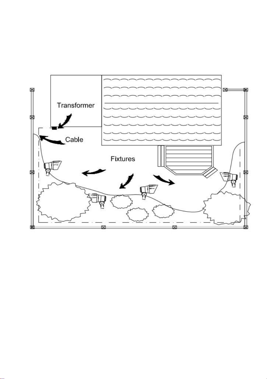
överskrider transformatorns klassificering. Dra lågspänningskabeln till
armaturerna; om det finns extra kabel, spola efter den sista fixturen.
VARNING: Brandrisk
Var noga med att lämna minst 10 fot (3m) kabel mellan nätaggregatet och
den första fixturen.
54、Fästa dina armaturer
Slå på transformatorn. Fäst dina armaturer till kabeln med
kabelanslutningar enligt bilden. Placera en kontakt på varje sida av kabeln
och tryck sedan ihop för att låsa. Pinnar kommer att tränga igenom kabeln
för att få kontakt, och dina armaturer bör lysa. Slå på transformatorn. Fäst
dina armaturer till kabeln med hjälp av kabelanslutningarna enligt bilden.
Tryck fast kontakten på kabeln tills stiften tränger igenom kabelns isolering.
Armaturen ska
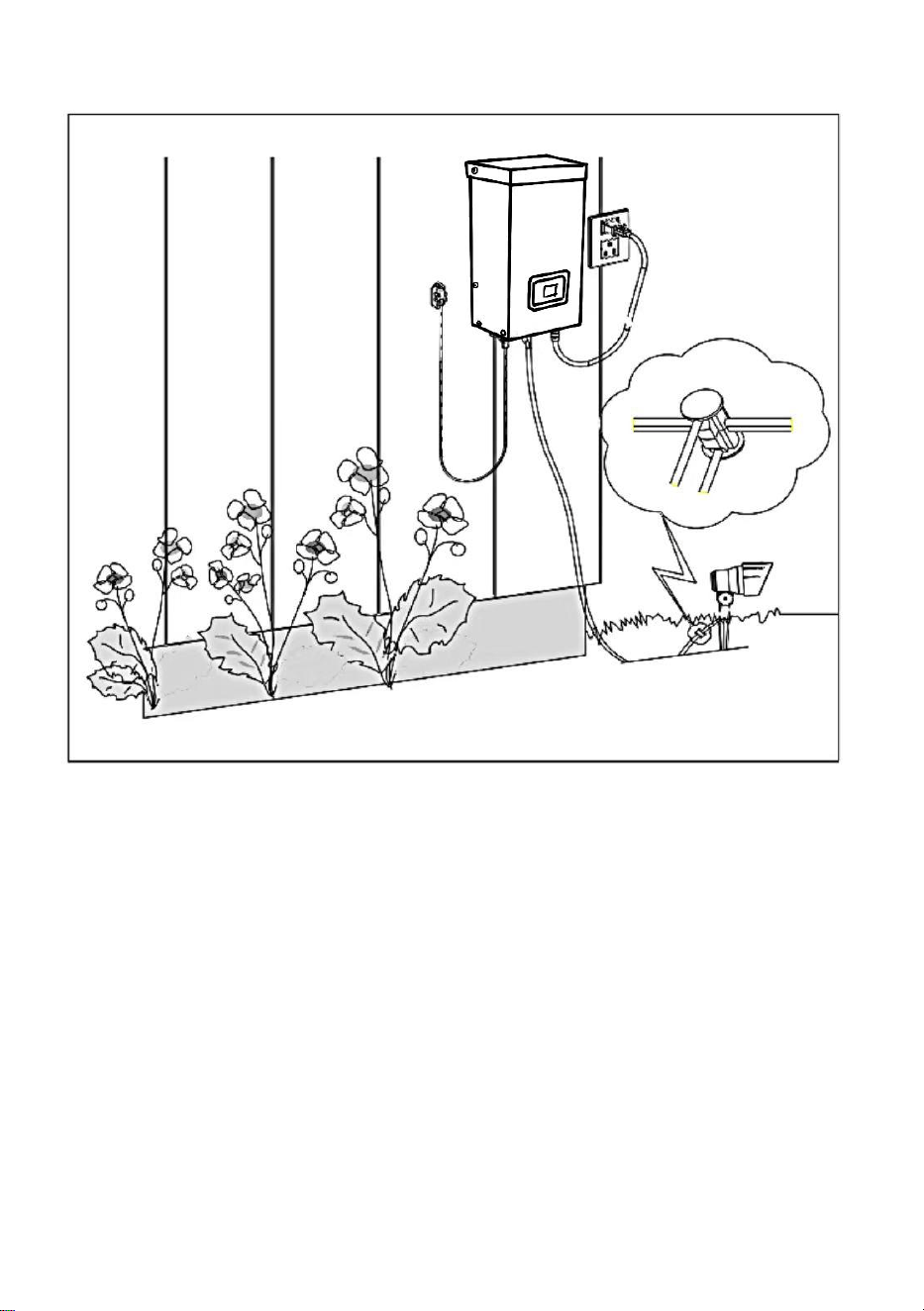
lysa.
55、Montering av transformatorn
För att montera direkt på en väggyta, använd de medföljande skruvarna
som visas, lämpliga för montering inom 39 tum till 59 tum (1 m till 1,5 m)
från marken. När du monterar skruvarna ska avståndet mellan . Häng
transformatorn (A) på
skruvarna.
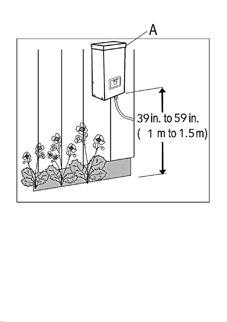
56、Montering av fotocellen
Montera fotocellens (B) fäste på en vägg eller annan fast yta. Snäpp fast
sensorn i fästet. Dra eller linda upp den överflödiga tråden för att skydda
den från gräsklippare, trimmers etc.
Undvik att rikta sensorn mot nattljuskällor som fönster, verandabelysning
och
gatubelysning.
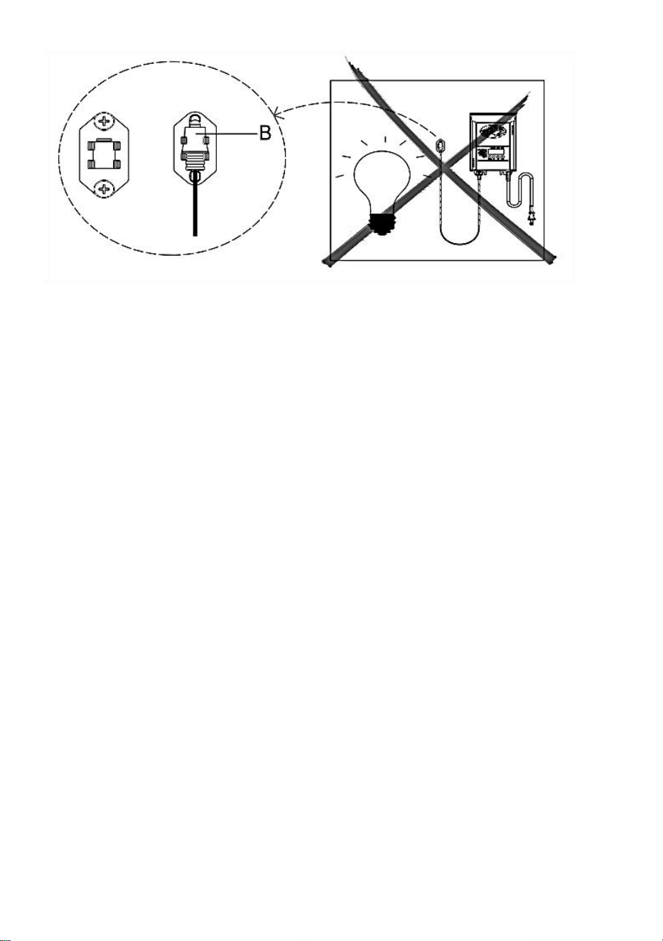
Placera sensorn i områden som får mindre solljus i skymningen (östra
sidan
av huset, bakom träd och buskar, under ett däck) kommer transformatorn
att slås på tidigare på kvällen. Om fotocellen monteras på ljusare ställen
kommer transformatorn att tändas när det har blivit mörkare ute.
Fotocellens placering, position och orientering kan justeras tills
transformatorn slås på vid önskad ljusnivå.
Om ledningarna till fotocellen är avskurna eller trasiga kan fotocellen bytas
ut. Skruva loss fotocellskontaktlocket från transformatorn och dra ut
bi-pin-kontakten ur det passande uttaget.
Ersättningsdelen sätts in i uttaget och locket skruvas tillbaka på uttaget för
att ge en vattentät anslutning.
Observera att bi-pin-kontakten är polariserad och kan endast sättas in i
uttaget på ett sätt.
Ersättningsfotocell finns i butiken.
7、 Skydda eller dölja kabeln
När alla fixturer är på plats och du är nöjd med dem
platser kan kabeln täckas med kompost eller grävas ner till
6 tum (15 cm) djup. Lämna cirka 30 cm (12 tum) kabel efter den
sista matchen.
VARNING: Brandrisk
Spola inte kabeln runt transformatorn. Den totala lampeffekten får inte
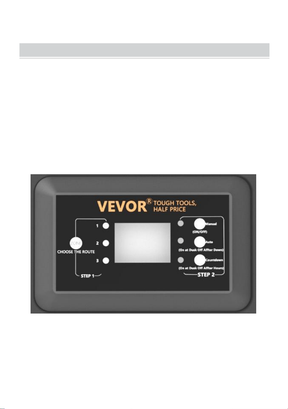
överstiga transformatorns maximala
effekt.
OPERATION
1、 Arbeta i manuellt läge
Med den här inställningen kan du omedelbart tända lamporna och stänga
av m när du inte längre behöver dem
a) STEG1 Tryck på ZONE . Välj den linje som behöver ställas in manuellt
(totalt 3 rader). Varje gång du trycker på ZONE kommer indikatorlampan
att tändas och motsvarande linjeindikator tänds för att indikera att linjen är
vald.
b) STEG2 Tryck på MANUAL . MANUELL-läget är nu aktiverat

2、Ställa in PHOTOCELL AUTO PÅ/AV
Denna inställning gör att fotocellen kan tända belysningen i skymningen
och släcka i gryningen
a ) STEG1 Tryck på ZONE. Välj den linje som behöver ställas in manuellt
(totalt 3 rader). Varje gång du trycker på ZONE kommer indikatorlampan
att tändas och motsvarande linjeindikator tänds för att indikera att linjen är
vald.
b ) STEG2 Tryck på AUTO tills AUTO LED-indikatorn lyser. FOTOCELL
AUTO PÅ/AV-läget är nu aktiverat. Sifferdisplayen visar
AU.

3、Ställa in PHOTOCELL PÅ/TID AV
Den här inställningen gör att fotocellen kan tända belysningen och du
ställer in när de ska släckas
a ) STEG1 Tryck på ZONE. Välj den linje som behöver ställas in manuellt
(totalt 3 rader). Varje gång du trycker på ZONE kommer indikatorlampan
att tändas och motsvarande linjeindikator tänds för att indikera att linjen är
vald.
b ) STEG2 Tryck på COUNTDOWN tills LED-indikatorn för COUNTDOWN
tänds. COUNTDOWN-läget är nu aktiverat.
c) Tryck på COUNTDOWN för att välja tid, med ett tidssteg på 1H och en
maximal inställning på 12H.
NOTERA:
När ett plötsligt strömavbrott inträffar och strömmen återställs, kommer
transformatorn att upprepa de tidigare inställningarna. Om ändringar
behövs måste du manuellt återställa önskat läge.

TROUBLESHOOTING
NOTERA:
Knapparna i den röda rutan är tre kretsskydd, motsvarande 1, 2 och 3 från
botten till toppen.
När knappen sticker ut representerar den motsvarande
utgångsöverbelastningsskydd. Efter att ha justerat belastningen, tryck på
motsvarande knapp för att återställa.
Tillverkad i Kina