Page 1
Shipping and Packing List
Package 1 of 1 contains:
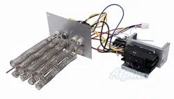
1 – Assembled electric heat section
1 – Circuit breaker cover
3 – Accessory kit labels
Check equipment for shipping damage. If you nd any
damage, immediately contact the last carrier.
WARNING
Improper installation, adjustment, alteration, service
or maintenance can cause property damage, personal
injury or loss of life. Installation and service must be
performed by a licensed professional HVAC installer or
equivalent, service agency, or the gas supplier.
CAUTION
As with any mechanical equipment, contact with sharp
sheet metal edges can result in personal injury. Take
care while handling this equipment and wear gloves and
protective clothing.
WARNING
Every working procedure that aects safety means shall
only be carried out by competent persons. This appliance
is not to be used by persons (including children) with
reduced physical, sensory or mental capabilities, or
lack of experience and knowledge, unless they have
been given supervision or instruction concerning use of
the appliance by a person responsible for their safety.
Children should be supervised to ensure they do not
play with the appliance.
WARNING
Maximum Altitude of application is 3200m above sea
level.
NOTE – Partial units shall only be connected to an appli-
ance suitable for the same refrigerant.
General Information
These instructions are intended to be a general guide and
do not supersede any local or national codes. Installation
must conform with the local building codes and with the
latest editions of the National Electric Code.
Be sure to disconnect all power to the unit while you install
and service this equipment. Use proper tools and protec-
tive equipment during installation and service.
Installation of air handler with or without optional electric
heat must conform with standards in the National Fire Pro-
tection Association (NFPA) “Standard for Installation of Air
Conditioning and Ventilation Systems NFPA No. 90A,”
and “Standard for Installation of Resident Type Warm Air
Heating and Air Conditioning System, No. 90B,” the man-
ufacturer’s installation instructions, and local municipal
building codes.
Electric Heat Sections
The electric heat sections provide eld-installed electric
heat for air handler units.
The ECB45 electric heat section is available with 4, 5, 7.5,
10, 12.5, 15 and 20 KW elements.
Refer to the applicable indoor unit product specications
bulletin (EHB) for heat section applications or unit Electric
Heat Accessory Kit label.
Heat Section Installation
WARNING
Before installing or servicing unit, be sure
ALL power to the unit is OFF. More than one
disconnect switch may be present. Electrical
shock can cause personal injury or death!
Before installing the unit, check information on the unit
rating plate to ensure that the unit meets the job specica-
tion, proper electrical power is available, and that proper
duct clearances are maintained.
NOTE – If installing heat sections at the same time as the
air handler unit, install the electric heat section in the air
handler unit before setting the air handler unit and attach-
ing the plenum.
INSTALLATION
INSTRUCTIONS
ELECTRIC HEAT SECTIONS
508507-02
05/2024
ECB45 Electric Heat Sections
Used with Air Handler Units
THIS MANUAL MUST BE LEFT WITH THE
HOMEOWNER FOR FUTURE REFERENCE
Page 2
1 - Shut o all power to the air handler unit. More than
one disconnect may be required.
2 - Remove air handler access panel and keep the
screws to reattach access panel after installing heat
elements.
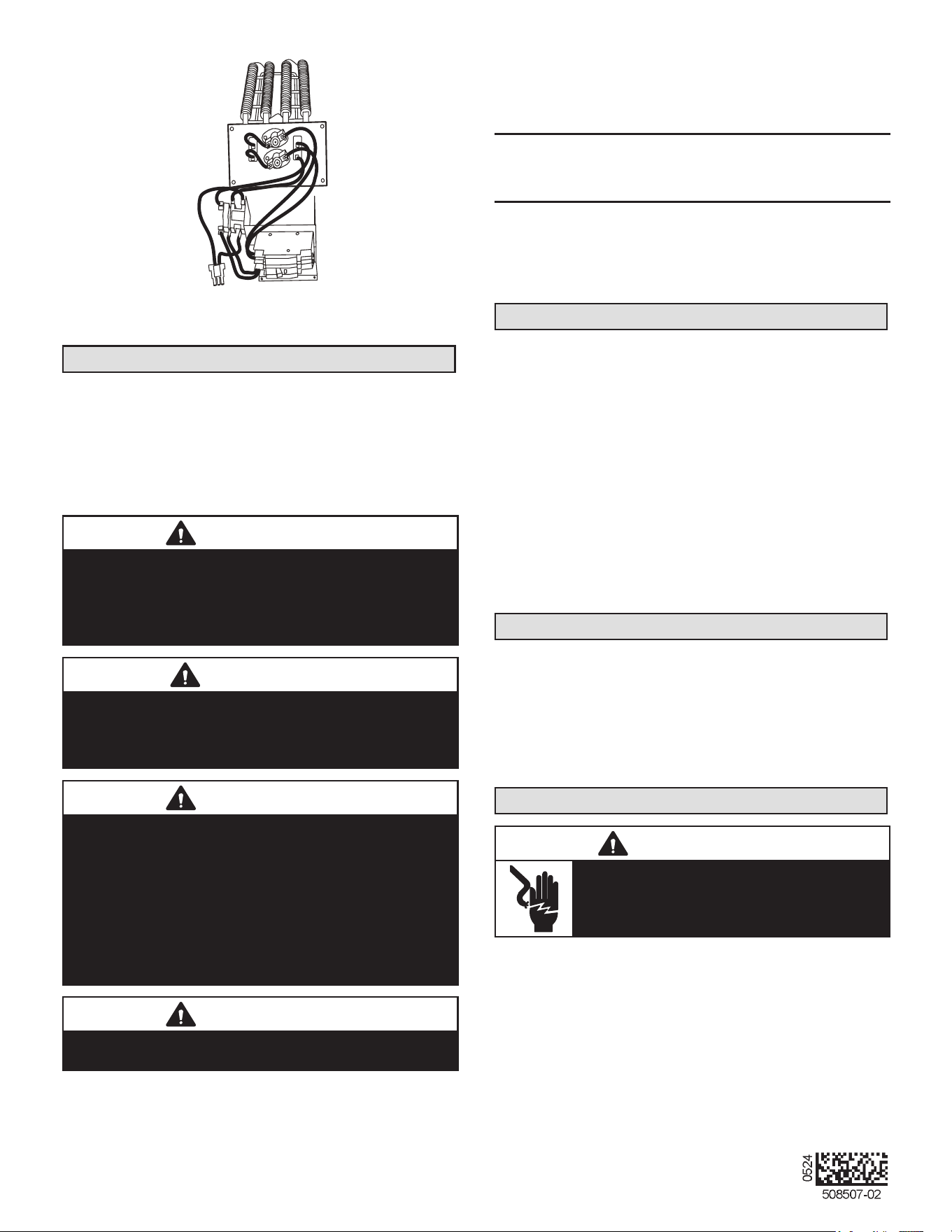
3 - Disconnect any existing eld supply wires and pull
them out of the air handler. Disconnect and remove
wiring harness and fastener (see gure 1). If not
removed, these items will prevent the heat section’s
base from resting properly in the compartment.
4 - Remove the no-heat seal plate in the air handler
frame (see gure 1).
NOTE – If a small heater is installed in the unit, the in-
staller will need to remove the no-heat plate and break it
apart at the perforations and reinstall the two pieces so
the smaller heater can be installed into the unit.
NO‐HEAT
SEAL PLATE
REMOVE SCREWS;
THEN REMOVE
NO-HEAT SEAL
PLATE
SEPARATE CONNECTOR;
DISCARD WIRE HARNESS
WIRE
HARNESS
REMOVE FASTENER SECURING WIRES
IF PRESENT
FIGURE 1. Prepare to Install Heat Element
5 - Slide the electric heat section into the air handler. Be
careful that the heating elements do not rub against
the sheet metal opening when they slide into the
air handler. The mounting holes should then line up
with holes in the air handler control box.
6 - Secure the electric heater assembly into place with
the screws that were removed from the No-Heat
plate. Install two eld-provided #8 SDST screws in
the front of the electric heater assembly (see gure
2).
INSTALL SCREWS
REMOVED FROM
THE NO-HEAT
SEAL PLATE.
INSTALL 2 FIELD-PROVIDED SCREWS TO SECURE THE
FRONT OF THE HEATER CIRCUIT BREAKER ASSEMBLY TO
THE FRONT FLANGE OF THE AIR HANDLER.
FIGURE 2. Installing the Heat Element Assembly
7 - The air handler’s access panels have a cover
plate that is fastened with a screw and will need to
be positioned to t either one breaker or two, but
do not install the access panel until all electrical
connections have been completed.
WARNING
Foil face insulation must be cut to eliminate the possibility
for any frayed foil to come in contact with any main or low
voltage connections. Insulation must be kept a minimum
of 1/2" away from any electrical connection.
Changing Circuit Breaker Orientation
The air handler comes from the factory ready for hori-
zontal right hand discharge installation. Always rotate the
breaker so up is the ON position in all orientations. The
circuit breaker orientation change is required by UL 1995,
Article 26.18 (25 September 2005).
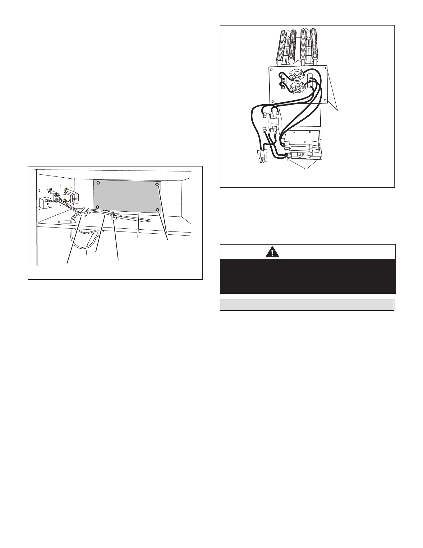
1 - Locate the one clip located on the right side
(see arrow) of each breaker (see gure 3). The
clip secures the circuit breaker to the mounting
bracket. Pull the clip to release the breaker from
the mounting bracket and rotate the breaker to the
proper postition.
Page 3
CLIP
BREAKER(S)
MOUNTING
BRACKET
NOTE - There may be only one clip securing
each circuit breaker.
CIRCUIT
BREAKER
FIGURE 3. Circuit Breaker Clip
2 - Install the circuit breaker cover plate.
FIGURE 4. Circuit Breaker Cover Plate
NOTE – If electric heat kit has only one circuit breaker, the
breaker cover plate needs to be moved up and installed
over the opening without the circuit breaker. Fasten the
breaker cover plate to the access panel using the circled
hole in gure 4. If the electric heat kit has two circuit break-
ers, the breaker cover plate is not required.
Electrical Connections
WARNING
Electric shock hazard! - Disconnect all power
supplies before servicing.
Replace all parts and panels before
operating.
Failure to do so can result in death or
electrical shock.
IMPORTANT
USE COPPER CONDUCTORS ONLY
NOTE – Refer to the nameplate on the air handler unit
for minimum circuit ampacity and maximum overcurrent
protection size.
The air handler units are provided with openings to be
used with 1-1/2 inch trade size (1-31/32 inch diameter)
conduit.
Electrical wiring, disconnect means and over-current pro-
tection are to be supplied by the installer. Refer to the air
handler rating plate for maximum over-current protection,
minimum circuit ampacity, as well as operating voltage.
If you want a single point power supply, refer to the name-
plate on the single point power supply accessory for min-
imum circuit ampacity and maximum overcurrent protec-
tion size. Select the proper supply circuit conductors in
accordance with tables 310-16 and 310-17 in the National
Electric Code, ANSI/NFPA No. 70 or tables 1 through 4 in
the Canadian Electric Code, Part I, CSA Standard C22.1.
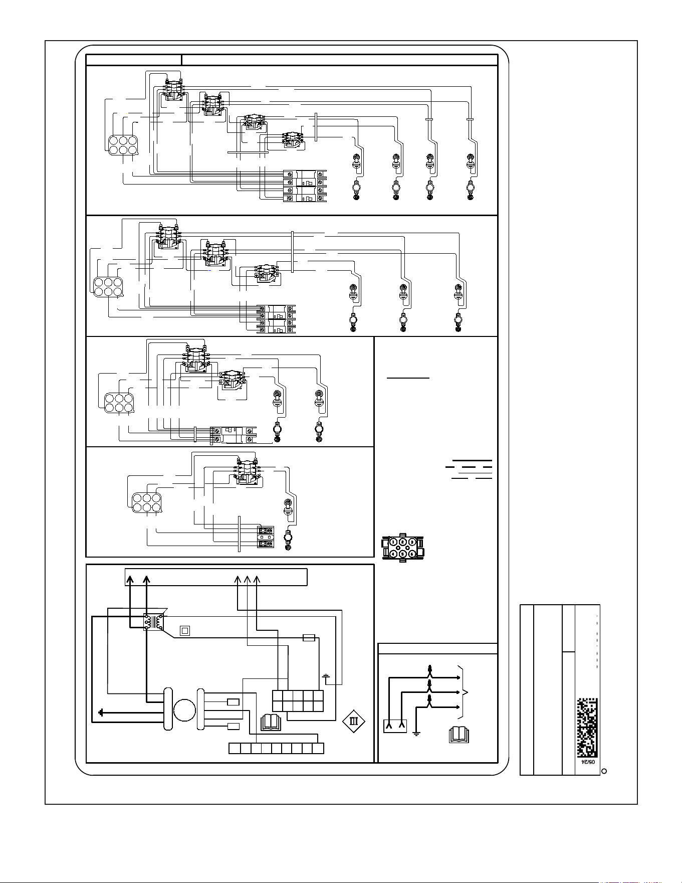
Refer to gure 13 for typical low voltage eld wiring for
air handler/condensing unit and heat pump applications.
Figure 8 is a diagram of the air handler connections and
the heater high-voltage wiring.
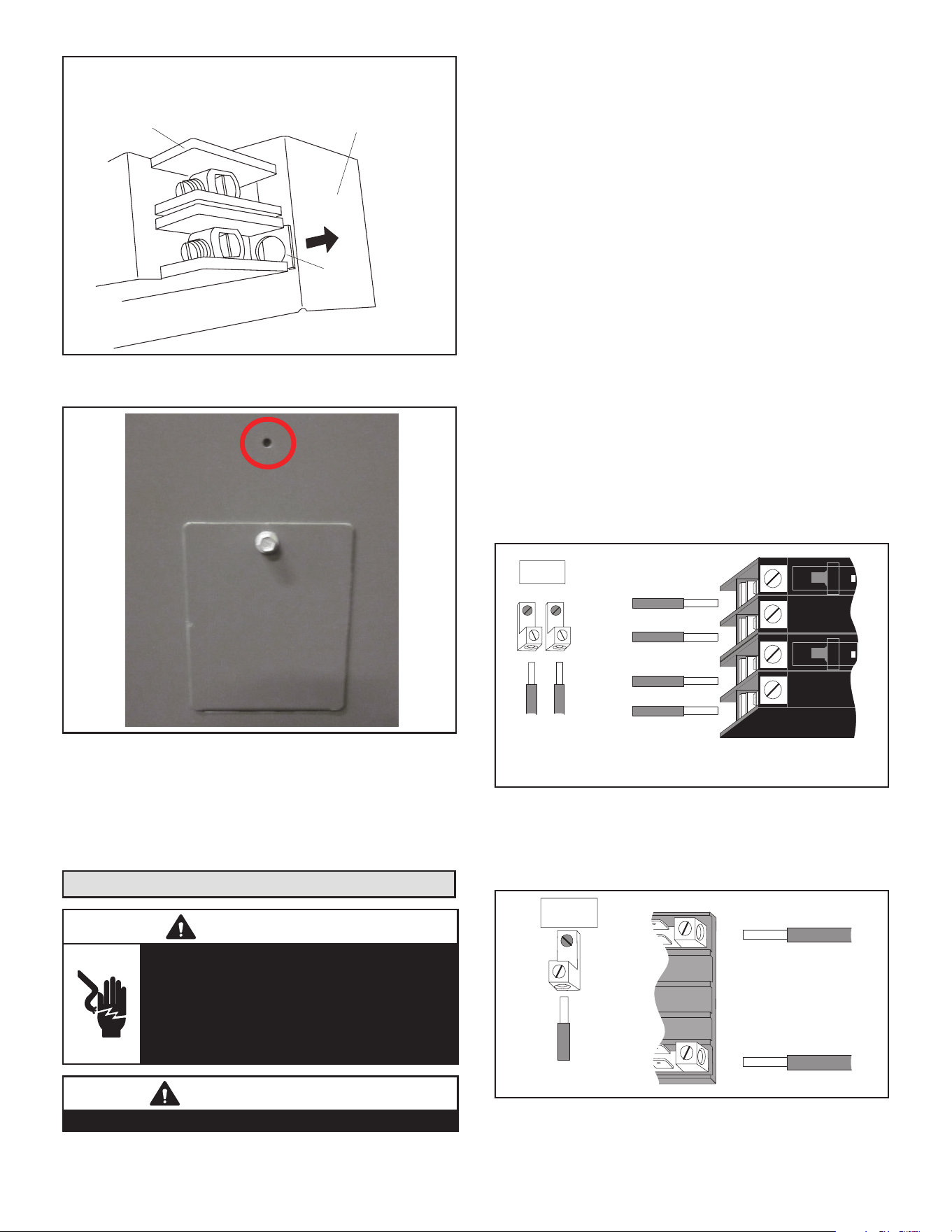
1 - Make wiring connections as follows:
Heaters equipped with circuit breakers —
Connect eld power supply wiring to circuit
breaker(s). Figure 5 shows L1, L2 and ground
(GND) connections for a 2-breaker conguration.
ON
OFF
60
ON
OFF
60
L1
L2
CIRCUIT 1
L1
L2
CIRCUIT 2
GND
208/240 VOLT FIELD
SUPPLY WIRES
Field Supply
Ground Wires
FIGURE 5. Field Power Supply Wiring
Heaters equipped with terminal blocks — Con-
nect eld power supply wiring to terminal block(s).
Figure 6 shows L1, L2 and ground (GND) connec-
tion for a terminal block conguration.
L1
L2
GND
208/240 VOLT FIELD
SUPPLY WIRES
FIELD SUPPLY
GROUND WIRES
FIGURE 6. Terminal Block Connections
Page 4
2 - Remove the interface harness from the air handler
unit and connect the 6-pin connector on the heater
assembly to the mating connector on the air handler
unit.
3 - For applications using a two-stage room thermostat
and/or an outdoor thermostat, connect wiring as
shown in gures 10 and 13.
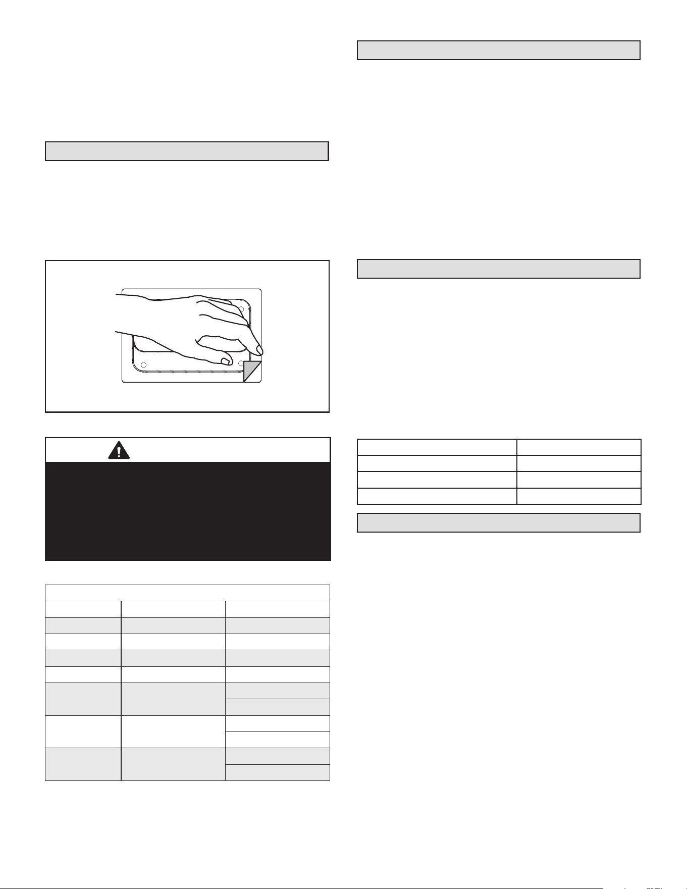
Circuit Breaker Cover Installation
1 - Remove any installed patch plates still present.
2 - Remove paper backing from the adhesive around
the perimeter of the back side of the circuit breaker
cover (gure 7).
3 - Position the breaker cover over the air handler
circuit breaker opening.
CIRCUIT BREAKER COVER
(BACKSIDE)
REMOVE PAPER COVERING
ADHESIVE BACK
FIGURE 7. Remove Paper Cover
IMPORTANT
Conrm air tight seal between breaker cover and air
handler access panel. Apply a thin silicone bead to the
adhesive back seat to ensure air tight seal.
Failure to seal circuit breaker cover will allow warm
moist air to be pulled into control panel which can create
condensation to form on the circuit breaker and other
electrical components within the control panel.
Electric Heat Circuit Breaker Ratings
Single Phase Circuit Breaker
Heat Size Voltage Breaker Size
4 kW 208/240V - 1 Phase 30A
5 kW 208/240V - 1 Phase 30A
7.5 kW 208/240V - 1 Phase 45A
10 kW 208/240V - 1 Phase 60A
12.5 kW 208/240V - 1 Phase 50A
25A
15 kW 208/240V - 1 Phase 60A
25A
20 kW 208/240V - 1 Phase 60A
50A
Air Handler Speed Connections
When using the electric heat sections with air handler
units, you must adjust the air handler speed according to
the size of electric heat and air handler unit.
• For air handlers with PSC motors, speed tap for electric
heat in upow and horizontal position is medium. Use
high speed tap for downow position.
• For air handlers with constant torque motors, speed tap
for electric heat in upow and horizontal position is tap
#4. Use tap #5, high speed tap, for downow position.
• For air handlers with variable speed motors, see air
handler instruction for additional information.
See applicable air handler installation instructions for air
handler speed adjustment procedure and location.
Label Installation
1 - Verify that current Unit Accessory Kit label is marked
with ECB45.
2 - If not, determine, per table 1 below, the applicable
replacement Accessory Kit Label.
3 - Peel label backing and apply correct Accessory Kit
Label over current unit label.
Electric Heat Accessory Kit Label Cross Reference
The following table provides a cross-reference for Acces-
sory Kit labels for each unit.
TABLE 1
Unit Type Accessory Kit Label #
CBA25UH, or PSC 581341-01
CBA25UHE, or Constant Torque 581342-01
CBA25UHV, or Variable Speed 581343-01
Unit Start-Up
1 - After all electrical connections have been completed
and jumpers congured (if required), replace the air
handler compartment access cover.
2 - Restore power to the unit.
3 - If using an electromechanical room thermostat, set
the thermostat heat anticipator to 0.4 amps.
4 - Set the thermostat above room temperature.
5 - Check the heat pump and the heat section for
normal operation.
6 - Set the thermostat to desired setting.
Page 5
Wiring Diagrams
Supersedes
Litho U.S.A.
C
2011
PSC LABEL WIRING DIAGRAM
15 AMP
L1
L2 OR
NEUT.
WIRING DIAGRAM: NO HEAT
14 GRN
2
14 BLK
1
GND
14 YEL(240V)
14 WHT(120V)
6-PIN
PLUG
14 YEL(COM)
14 BLK(HI)
14 RED(LO)
2
YEL
1
CAP
MTR
BLK
RED
3
BRN/WHT
BRN
GND
C
24
HEATERS USED
LOCATION
PLUG PIN
CONTROL CIRCUIT WIRING TO BE
24 VOLT, N.E.C. CLASS 2
W2
BLU
WHT
GRN
RED
W1
C
18 BLU
18 WHT
G
R
18 GRN
18 RED
BLK
14 YEL L2
14 BLK L1
24V
COM
208V
18 BLU
240V
14 BLK
1
3
5
2
6
4
18 BLU
6
54
32
1
18 GRN
18 BLK
14 RED
18 BLU
18 RED
1
2
3
5
14 BLUE (MED)
BLUE
4
#
TRANSFORMER
BLOWER
REALY
TIME DELAY
ON
1-20
20-60
20-60
OFF
40-110
1-30
1-30
ON
30-90
30-90
OFF
1-30
1-30
# FACTORY SPEED SET TO MEDIUM (BLUE)
ELECTRIC HEAT
3
6
12
5 4
BLK
YEL
BLK
YEL
RED
YEL
BLK
HTR 1
RED
WHT
BLU
HTR 1
4KW & 5KW
OFF
ON
7.5KW & 10KW
BLK
BLK
YEL
YEL
RED
BLK
BLK
YEL
YEL
RED
WHT
BLU
BLU
WHT
3
6
12
5 4
HTR1
HTR2
YEL
BLK
L1
L2
WIRING DIAGRAM - ELECTRIC HEATPART NO. 537980-03
OFF
ON
OFF
ON
12.5KW & 15KW
L1
L2
L1
L2
BLK
YEL
BLK
YEL
BLU
BLK
YEL
BLK
BLK
YEL
YEL
RED
WHT
RED
WHT
BLU
3
6
12
5 4
BLK
BLK
YEL
BLK
BLU
YEL
BLK
OFF
ON
OFF
ON
BLK
BLK
YEL
YEL
BLK
BLK
20KW
3
6
12
5 4
BLK
RED
WHT
BLU
BLK
BLK
RED
WHT
BLU
YEL
YEL
BLK
YEL
YEL
YEL
BLU
BLK
BLU
BLK
BLK
YEL
YEL
BLK
SEQ
SEQ
SEQ
SEQ
SEQ
SEQ
SEQ
SEQ
SEQ
SEQ
PRI LS PRI LS
L1
L2
L1
L2
CB
CB
CB OR TB
CB OR TB
Cut Size 5-3/4" Wide x 10-3/8" Tall
HTR 1
SEC L
HTR 2
SEC L
HTR 3
SEC L
HTR 4
SEC L
HTR 1
PRI LS
HTR 2
PRI LS
HTR 3
PRI LS
HTR 4
PRI LS
HTR 1
SEC L
HTR 2
SEC L
HTR 3
SEC L
HTR 1
PRI LS
HTR 2
PRI LS
HTR 2
PRI LS
HTR 2
PRI LS
HTR 3
PRI LS
4KW & 5 KW = HTR1
7.5 & 10 KW = HTR1 & HTR2
15 KW = HTR1,HTR2 & HTR3
20 KW = HTR1,HTR2,HTR3 & HTR4
TB = TERMINAL BLOCK
CB = CIRCUIT BREAKER
SEQ = SEQUENCER
GND = GROUND LUG
PRI LS= LIMIT SWITCH
SEC L= LIMIT SWITCH
HTR = HEATER ELEMENT
POWER (FACTORY WIRED)
POWER (FIELD WIRED)
CONTROL (FACTORY WIRED)
CONTROL (FIELD WIRED)
THREE POLE SEQUENCER
TIMING - SEC
THREE POLE SEQUENCER
TIMING - SEC
**TD = TIME DELAY (OPT.)
TR = TRANSFORMER
BR = BLOWER RELAY
MTR = BLOWER MOTOR
CAP = MOTOR CAPACITOR
GND = GROUND
CONNECTION
TO
THERMOSTAT
BY OTHERS
WIRE NUTS
BY
OTHERS
SUPPLY
VOLTAGE
HTR 2
SEC L
HTR 1
SEC L
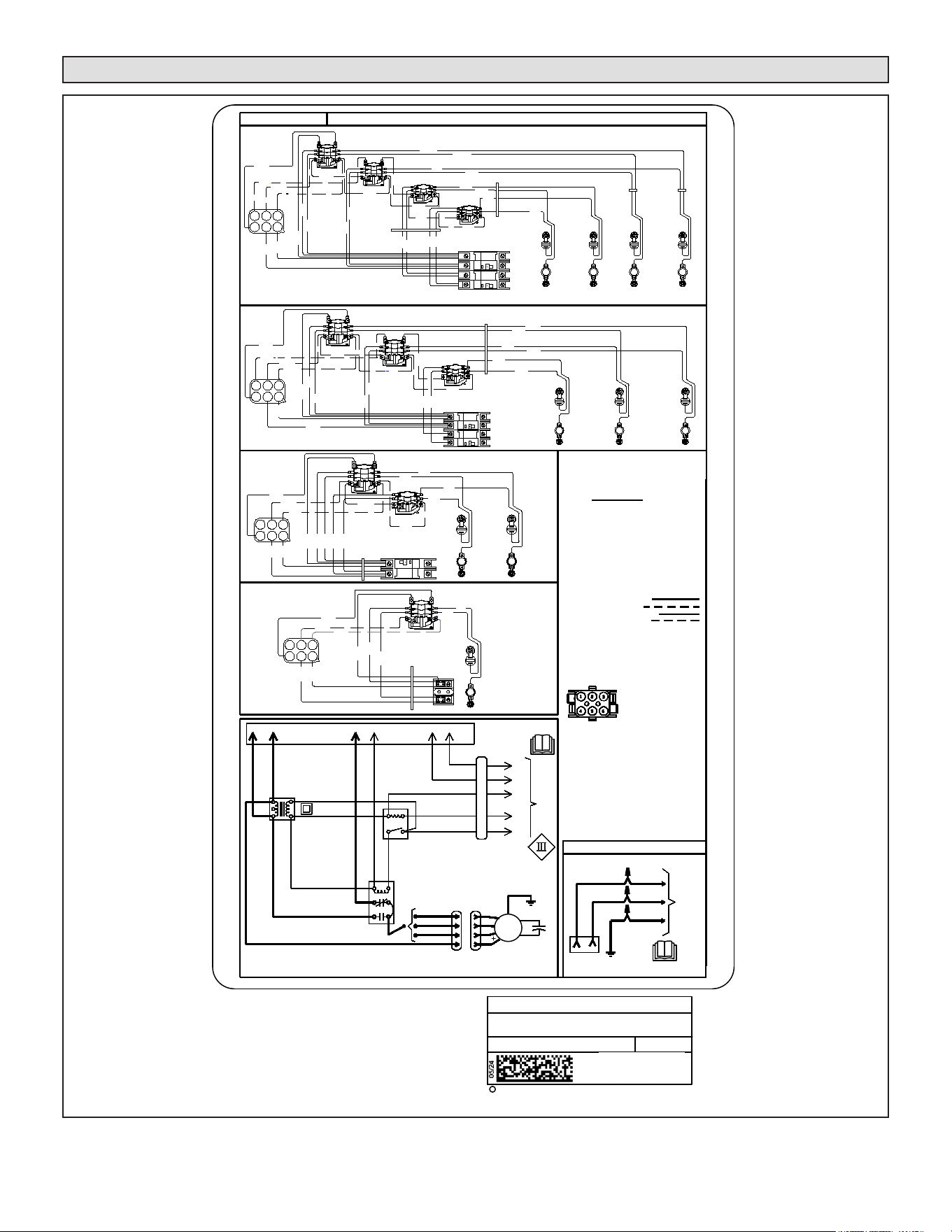
FIGURE 8. Typical Wiring Diagram – Air Handler with Electric Heat – PSC Motor

Page 6
Supersedes
Litho U.S.A.
C
2011
CONSTANT TORQUE LABEL WIRING
DIAGRAM
ELECTRIC HEAT
L1
L2 OR
NEUT.
WIRING DIAGRAM: NO HEAT
14 GRN
2
14 BLK
1
14 YEL(240V)
14 WHT(120V)
6-PIN
PLUG
5
C
L
N
G
14 GREEN
GND
6-PIN CAP
14 YEL
14 YEL
18 BLU
18 BLU
18 BRN
18 BLK
18 WHT
18 YEL
18 GREEN
18 WHT
18 BLK
18 BLU
18 RED
TRANSFORMER
18 BLU
1
2 4 5 6
14 BLK
240V
208V
COM
24V
14 BLK L1
14 YEL L2
24
C
3
4
MTR
1
2
14 BLK
14 YEL
TERMINAL STRIP
18 YEL
18 GREEN
18 RED
TO THERMOSTAT BY OTHERS
18 BLK
18 WHT
18 BLU
W2
W1
O
G
R
DS
C
Y2
Y1
W2
W1
G
R
C
Y1
GND
LOCATION
PLUG PIN
ON
1-20
20-60
20-60
OFF
40-110
1-30
1-30
ON
30-90
30-90
OFF
1-30
1-30
3
6
12
5 4
BLK
YEL
BLK
YEL
RED
YEL
BLK
HTR 1
RED
WHT
BLU
HTR 1
4KW & 5KW
OFF
ON
7.5KW & 10KW
BLK
BLK
YEL
YEL
RED
BLK
BLK
YEL
YEL
RED
WHT
BLU
BLU
WHT
3
6
12
5 4
HTR1
HTR2
YEL
BLK
L1
L2
WIRING DIAGRAM - ELECTRIC HEATPART NO. 537981-04
OFF
ON
OFF
ON
12.5KW & 15KW
L1
L2
L1
L2
BLK
YEL
BLK
YEL
BLU
BLK
YEL
BLK
BLK
YEL
YEL
RED
WHT
RED
WHT
BLU
3
6
12
5 4
BLK
BLK
YEL
BLK
BLU
YEL
BLK
OFF
ON
OFF
ON
BLK
BLK
YEL
YEL
BLK
BLK
20KW
3
6
12
5 4
BLK
RED
WHT
BLU
BLK
BLK
RED
WHT
BLU
YEL
YEL
BLK
YEL
YEL
YEL
BLU
BLK
BLU
BLK
BLK
YEL
YEL
BLK
SEQ
SEQ
SEQ
SEQ
SEQ
SEQ
SEQ
SEQ
SEQ
SEQ
PRI LS PRI LS
L1
L2
L1
L2
CB
CB
CB OR TB
CB OR TB
GND
Cut size: 7" Wide x 9-1/2" Tall
HTR 1
SEC L
HTR 2
SEC L
HTR 3
SEC L
HTR 4
SEC L
HTR 1
PRI LS
HTR 2
PRI LS
HTR 3
PRI LS
HTR 4
PRI LS
HTR 1
PRI LS
HTR 2
PRI LS
HTR 3
PRI LS
HEATERS USED
4KW & 5 KW = HTR1
7.5 & 10 KW = HTR1 & HTR2
15 KW = HTR1,HTR2 & HTR3
20 KW = HTR1,HTR2,HTR3 & HTR4
TB = TERMINAL BLOCK
CB = CIRCUIT BREAKER
SEQ = SEQUENCER
GND = GROUND LUG
PRI LS= LIMIT SWITCH
SEC L= LIMIT SWITCH
HTR = HEATER ELEMENT
CONTROL CIRCUIT WIRING TO BE
24 VOLT, N.E.C. CLASS 2
POWER (FACTORY WIRED)
POWER (FIELD WIRED)
CONTROL (FACTORY WIRED)
CONTROL (FIELD WIRED)
THREE POLE SEQUENCER
TIMING - SEC
THREE POLE SEQUENCER
TIMING - SEC
**TD = TIME DELAY (OPT.)
TR = TRANSFORMER
BR = BLOWER RELAY
MTR = BLOWER MOTOR
CAP = MOTOR CAPACITOR
GND = GROUND
CONNECTION
WIRE NUTS
BY
OTHERS
SUPPLY
VOLTAGE
15 AMP
HTR 1
SEC L
HTR 2
SEC L
HTR 3
SEC L
HTR 2
SEC L
HTR 1
SEC L
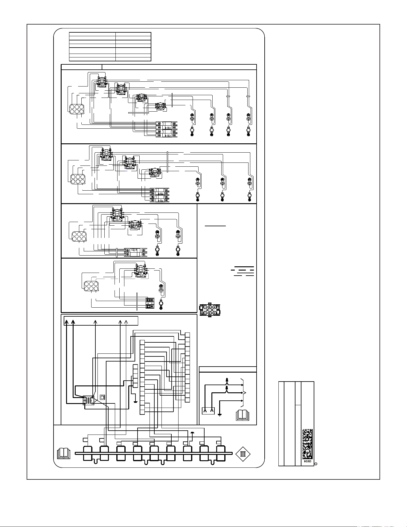
FIGURE 9. Typical Wiring Diagram – Air Handler with Electric Heat – Constant Torque Motor
Page 7
Supersedes
Litho U.S.A.
C
2011
VARIABLE SPEED LABEL WIRING
DIAGRAM
ELECTRIC HEAT
SYSTEM FIELD JUMPERS
SINGLE STAGE AIR CONDITIONER NEED ALL
TWO-STAGE AIR CONDITIONER REMOVE Y1 TO Y2
SINGLE STAGE HEAT PUMP REMOVE R TO O
TWO-STAGE HEAT PUMP
REMOVE Y1 TO Y2 AND R
TO O
TWO-STAGE ELECTRIC HEAT REMOVE W1 TO W2
TO ACTIVATE DEHUMIDIFICATION REMOVE R TO DS
15 AMP
SUPPLY
VOLTAGE
L1
L2 OR
NEUT.
WIRING DIAGRAM: NO HEAT
WIRE NUTS
BY
OTHERS
14 GRN
2
14 BLK
1
14 YEL(240V)
14 WHT(120V)
6-PIN
PLUG
C
R
14 YEL L2
14 BLK L1
COM
208V
240V
6
54
2
1
1
2
3
4
5
1
2
3
4
5
6
8
9
10
11
12
13
14
15
7
1
2
3
4
5
6
8
9
10
11
12
13
14
15
7
16
Y2
DS
O
W1
W2
Y1
G
18 BLUE L2
18 WHITE L2
18 BLACK L2
R
CIRCUIT BOARD
MOTOR
TR
GRD
18 YEL
18 ORG
18 PRPLE
18 BLUE/WHITE
18 GRN
18 RED
18 WHITE
18 BLK
18 RED
18 YEL
18 BLUE
18 RED
18 YEL
14 YEL
14 BLK
18 WHITE
18 WHITE
18 WHITE
18 WHITE
18 WHITE
18 WHITE
18 WHITE
18 WHITE
18 ORANGE
18 PURPLE
18 WHITE
18 WHITE
18 WHITE
18 YELLOW
18 GRN
C
18 BLUE
WARNING
USE COPPER CONDUCTORS
ONLY
W2
W1
O
G
R
DS
C
Y2
Y1
GND
W2
W1
G
O
R
DS
C
Y1
Y2
3
6
12
5 4
BLK
YEL
BLK
YEL
RED
YEL
BLK
HTR 1
RED
WHT
BLU
HTR 1
4KW & 5KW
OFF
ON
7.5KW & 10KW
BLK
BLK
YEL
YEL
RED
BLK
BLK
YEL
YEL
RED
WHT
BLU
BLU
WHT
3
6
12
5 4
HTR1
HTR2
YEL
BLK
L1
L2
WIRING DIAGRAM - ELECTRIC HEAT
PART NO. 537982-04
OFF
ON
OFF
ON
12.5KW & 15KW
L1
L2
L1
L2
BLK
YEL
BLK
YEL
BLU
BLK
YEL
BLK
BLK
YEL
YEL
RED
WHT
RED
WHT
BLU
3
6
12
5 4
BLK
BLK
YEL
BLK
BLU
YEL
BLK
OFF
ON
OFF
ON
BLK
BLK
YEL
YEL
BLK
BLK
20KW
HTR 1
PRI LS
HTR 2
PRI LS
HTR 3
PRI LS
HTR 4
PRI LS
3
6
12
5 4
BLK
RED
WHT
BLU
BLK
BLK
RED
WHT
BLU
YEL
YEL
BLK
YEL
YEL
YEL
BLU
BLK
BLU
BLK
BLK
YEL
YEL
BLK
HTR 4
SEC L
HTR 3
SEC L
HTR 2
SEC L
HTR 1
SEC L
SEQ
SEQ
SEQ
SEQ
SEQ
SEQ
SEQ
SEQ
SEQ
SEQ
PRI LS PRI LS
L1
L2
L1
L2
CB
CB
CB OR TB
CB OR TB
PLUG PIN
LOCATION
THREE POLE SEQUENCER
TIMING - SEC
ON
1-20
20-60
20-60
OFF
40-110
1-30
1-30
TWO POLE SEQUENCER
TIMING - SEC
ON
30-90
30-90
OFF
1-30
1-30
GND
CUT SIZE: 6-3/4"Wide x 10-3/4" Tall
HTR 3
SEC L
HTR 2
SEC L
HTR 1
SEC L
HTR 1
PRI LS
HTR 2
PRI LS
HTR 3
PRI LS
4KW & 5 KW = HTR1
7.5 & 10 KW = HTR1 & HTR2
15 KW = HTR1,HTR2 & HTR3
20 KW = HTR1,HTR2,HTR3 & HTR4
HEATERS USED
TB = TERMINAL BLOCK
CB = CIRCUIT BREAKER
SEQ = SEQUENCER
GND = GROUND LUG
PRI LS= LIMIT SWITCH
SEC L= LIMIT SWITCH
HTR = HEATER ELEMENT
CONTROL CIRCUIT WIRING TO BE
24 VOLT, N.E.C. CLASS 2
POWER (FACTORY WIRED)
POWER (FIELD WIRED)
CONTROL (FACTORY WIRED)
CONTROL (FIELD WIRED)
**TD = TIME DELAY (OPT.)
TR = TRANSFORMER
BR = BLOWER RELAY
MTR = BLOWER MOTOR
CAP = MOTOR CAPACITOR
GND = GROUND
CONNECTION
HTR 2
SEC L
HTR 1
SEC L
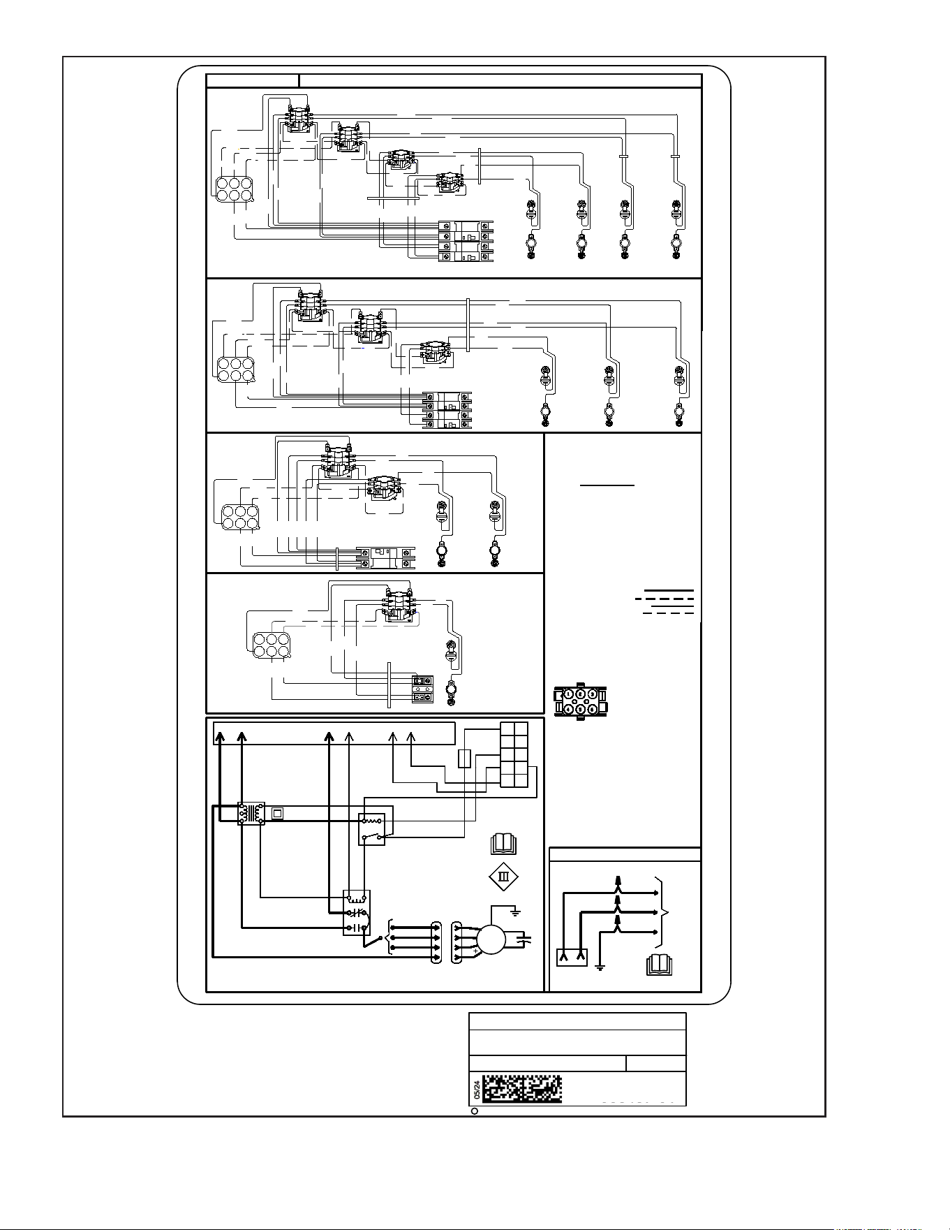
FIGURE 10. Typical Wiring Diagram – Air Handler with Electric Heat – Variable-Speed Motor
Page 8
Supersedes
Litho U.S.A.
C
2011
PSC LABEL WIRING DIAGRAM
15 AMP
SUPPLY
VOLTAGE
L1
L2 OR
NEUT.
WIRING DIAGRAM: NO HEAT
WIRE NUTS
BY
OTHERS
14 GRN
2
14 BLK
1
GND
14 YEL(240V)
14 WHT(120V)
6-PIN
PLUG
14 YEL(COM)
14 BLK(HI)
14 RED(LO)
2
YEL
1
CAP
MTR
BLK
RED
3
BRN/WHT
BRN
GND
C
24
HEATERS USED
18 BLU
18 WHT
18 GRN
18 RED
14 YEL L2
14 BLK L1
24V
COM
208V
18 BLU
240V
14 BLK
1
3
5
2
6
4
18 BLU
6
54
32
1
18 GRN
18 BLK
14 RED
18 BLU
18 RED
1
2
3
5
14 BLUE (MED)
BLUE
4
#
TRANSFORMER
BLOWER
RELAY
TIME DELAY
ON
1-20
20-60
20-60
OFF
40-110
1-30
1-30
ON
30-90
30-90
OFF
1-30
1-30
# FACTORY SPEED SET TO MEDIUM (BLUE)
ELECTRIC HEAT
3
6
12
5 4
BLK
YEL
BLK
YEL
RED
YEL
BLK
HTR 1
RED
WHT
BLU
HTR 1
4KW & 5KW
OFF
ON
7.5KW & 10KW
BLK
BLK
YEL
YEL
HTR1
SEC L
HTR2
SEC L
RED
BLK
BLK
YEL
YEL
RED
WHT
BLU
BLU
WHT
3
6
12
5 4
HTR1
HTR2
YEL
BLK
L1
L2
WIRING DIAGRAM - ELECTRIC HEATPART NO. 538437-01
OFF
ON
OFF
ON
12.5KW & 15KW
HTR2
PRI LS
HTR3
PRI LS
L1
L2
L1
L2
HTR1
SEC L
HTR2
SEC L
BLK
YEL
BLK
YEL
BLU
BLK
YEL
BLK
BLK
YEL
YEL
RED
WHT
RED
WHT
BLU
3
6
12
5 4
BLK
BLK
YEL
BLK
BLU
YEL
BLK
OFF
ON
OFF
ON
BLK
BLK
YEL
YEL
BLK
BLK
20KW
HTR 1
PRI LS
HTR 2
PRI LS
HTR 3
PRI LS
HTR 4
PRI LS
3
6
12
5 4
BLK
RED
WHT
BLU
BLK
BLK
RED
WHT
BLU
YEL
YEL
BLK
YEL
YEL
YEL
BLU
BLK
BLU
BLK
BLK
YEL
YEL
BLK
HTR 3
SEC L
HTR 2
SEC L
HTR 1
SEQ
SEQ
SEQ
SEQ
SEQ
SEQ
SEQ
SEQ
SEQ
SEQ
PRI LS PRI LS
SEC L
L1
L2
L1
L2
CB
CB
CB OR TB
CB OR TB
Cut Size 5-3/4" Wide x 10-3/8" Tall
R
O
G
W1
W2
Y2
Y1
C
DS
F1
4 KW & 5 KW = HTR1.
7.5 & 10KW = HTR1, HTR2
12.5 KW & 15KW = HTR1, HTR2 & HTR3
20 KW = HTR1, HTR2,HTR3 & HTR4
TB = TERMINAL BLOCK
CB = CIRCUIT BREAKER
SEQ = SEQUENCER
GND = GROUND LUG
PRI LS= LIMIT SWITCH
SEC L= LIMIT SWITCH
HTR = HEATER ELEMENT
CONTROL CIRCUIT WIRING TO
BE 24 VOLT, N.E.C. CLASS 2
THREE POLE SEQUENCER
TIMING - SEC
THREE POLE SEQUENCER
TIMING - SEC
PLUG PIN
LOCATION
**TD = TIME DELAY (OPT.)
TR = TRANSFORMER
BR = BLOWER RELAY
MTR = BLOWER MOTOR
CAP = MOTOR CAPACITOR
GND = GROUND CONNECTION
F1 = FUSE 3 AMP, BLADE TYPE, 32V
HTR2
PRI LS
HTR3
SEC L
HTR 4
SEC L
POWER (FACTORY WIRED)
POWER (FIELD WIRED)
CONTROL (FACTORY WIRED)
CONTROL (FIELD WIRED)
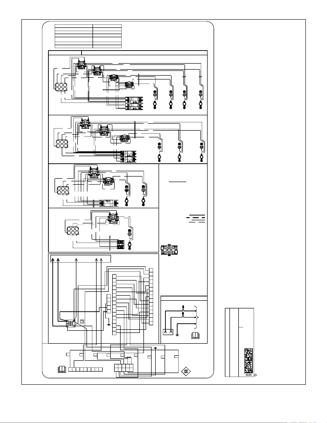
FIGURE 11. Air Handler with Electric Heat – PSC Motor – RDS Controller
Page 9
Supersedes
Litho U.S.A.
C
2011
CONSTANT TORQUE LABEL WIRING
DIAGRAM
ELECTRIC HEAT
L1
L2 OR
NEUT.
WIRING DIAGRAM: NO HEAT
14 GRN
2
14 BLK
1
14 YEL(240V)
14 WHT(120V)
5
C
L
N
G
14 GREEN
GND
6-PIN CAP
14 YEL
14 YEL
18 BLU
18 BLU
18 BRN
18 BLK
18 WHT
18 YEL
18 GREEN
18 WHT
18 BLK
18 BLU
18 RED
TRANSFORMER
18 BLU
1
2 4 5 6
14 BLK
240V
208V
COM
24V
14 BLK L1
14 YEL L2
24
C
3
4
MTR
1
2
14 BLK
14 YEL
18 RED
18 BLK
18 WHT
18 BLU
GND
PLUG PIN
LOCATION
THREE POLE SEQUENCER
TIMING - SEC
ON
1-20
20-60
20-60
OFF
40-110
1-30
1-30
TWO POLE SEQUENCER
TIMING - SEC
ON
30-90
30-90
OFF
1-30
1-30
3
6
12
5 4
BLK
YEL
BLK
YEL
RED
YEL
BLK
HTR 1
RED
WHT
BLU
HTR 1
4KW & 5KW
OFF
ON
7.5KW & 10KW
BLK
BLK
YEL
YEL
HTR1
HTR2
RED
BLK
BLK
YEL
YEL
RED
WHT
BLU
BLU
WHT
3
6
12
5 4
HTR1
HTR2
YEL
BLK
L1
L2
WIRING DIAGRAM - ELECTRIC HEATPART NO. 538348-01
OFF
ON
OFF
ON
12.5KW & 15KW
HTR1
PRI LS
HTR2
PRI LS
HTR3
PRI LS
L1
L2
L1
L2
HTR1
SEC L
HTR2
SEC L
HTR3
SEC L
BLK
YEL
BLK
YEL
BLU
BLK
YEL
BLK
BLK
YEL
YEL
RED
WHT
RED
WHT
BLU
3
6
12
5 4
BLK
BLK
YEL
BLK
BLU
YEL
BLK
OFF
ON
OFF
ON
BLK
BLK
YEL
YEL
BLK
BLK
20KW
HTR 1
PRI LS
HTR 2
PRI LS
HTR 3
PRI LS
HTR 4
PRI LS
3
6
12
5 4
BLK
RED
WHT
BLU
BLK
BLK
RED
WHT
BLU
YEL
YEL
BLK
YEL
YEL
YEL
BLU
BLK
BLU
BLK
BLK
YEL
YEL
BLK
HTR 4
SEC L
HTR 3
SEC L
HTR 2
SEC L
HTR 1
SEC L
SEQ
SEQ
SEQ
SEQ
SEQ
SEQ
SEQ
SEQ
SEQ
SEQ
PRI LS PRI LS
SEC L
SEC L
L1
L2
L1
L2
CB
CB
CB OR TB
CB OR TB
GND
Cut size: 7" Wide x 9-1/2" Tall
R
O
G
W1
W2
Y2
Y1
C
DS
F1
4 KW & 5 KW = HTR1
7.5 & 10 KW = HTR1 & HTR2
12.5 KW & 15 KW = HTR1,HTR2 & HTR3
20 KW = HTR1,HTR2,HTR3 & HTR4
HEATERS USED
TB = TERMINAL BLOCK
CB = CIRCUIT BREAKER
SEQ = SEQUENCER
GND = GROUND LUG
PRI LS= LIMIT SWITCH
SEC L= LIMIT SWITCH
HTR = HEATER ELEMENT
POWER (FACTORY WIRED)
POWER (FIELD WIRED)
CONTROL (FACTORY WIRED)
CONTROL (FIELD WIRED)
CONTROL CIRCUIT WIRING TO
BE 24 VOLT, N.E.C. CLASS 2
**TD = TIME DELAY (OPT.)
TR = TRANSFORMER
BR = BLOWER RELAY
MTR = BLOWER MOTOR
CAP = MOTOR CAPACITOR
GND = GROUND
CONNECTION
F1 = FUSE 3 AMP, BLADE TYPE, 32V
R
O
G
W1
W2
Y2
Y1
C
DS
WIRE NUTS
BY
OTHERS
15 AMP
SUPPLY
VOLTAGE
6-PIN
PLUG
RDS CONTROL BOARD
FIGURE 12. Air Handler with Electric Heat – Constant Torque Motor – RDS Controller
Page 10
Supersedes
Litho U.S.A.
C
2011
VARIABLE SPEED LABEL WIRING
DIAGRAM
ELECTRIC HEAT
CUT SIZE: 6-3/4"Wide x 10-3/4" Tall
SYSTEM FIELD JUMPERS
SINGLE STAGE AIR CONDITIONER NEED ALL
TWO-STAGE AIR CONDITIONER REMOVE Y1 TO Y2
SINGLE STAGE HEAT PUMP REMOVE R TO O
TWO-STAGE HEAT PUMP
REMOVE Y1 TO Y2 AND R
TO O
TWO-STAGE ELECTRIC HEAT REMOVE W1 TO W2
TO ACTIVATE DEHUMIDIFICATION REMOVE R TO DS
15 AMP
SUPPLY
VOLTAGE
L1
L2 OR
NEUT.
WIRING DIAGRAM: NO HEAT
WIRE NUTS
BY
OTHERS
14 GRN
2
14 BLK
1
14 YEL(240V)
14 WHT(120V)
6-PIN
PLUG
C
R
14 YEL L2
14 BLK L1
COM
208V
240V
6
54
2
1
1
2
3
4
5
1
2
3
4
5
6
8
9
10
11
12
13
14
15
7
1
2
3
4
5
6
8
9
10
11
12
13
14
15
7
16
Y2
DS
O
W1
W2
Y1
G
18 BLUE L2
18 WHITE L2
18 BLACK L2
R
CIRCUIT BOARD
MOTOR
TR
GRD
18 YEL
18 ORG
18 PRPLE
18 BLUE/WHITE
18 GRN
18 RED
18 WHITE
18 BLK
18 RED
18 YEL
18 BLUE
18 RED
18 YEL
14 YEL
14 BLK
18 WHITE
18 WHITE
18 WHITE
18 WHITE
18 WHITE
18 WHITE
18 WHITE
18 WHITE
18 ORANGE
18 PURPLE
18 WHITE
18 WHITE
18 WHITE
18 YELLOW
18 GRN
C
18 BLUE
WARNING
USE COPPER CONDUCTORS
ONLY
GND
W2
W1
G
O
R
DS
C
Y1
Y2
3
6
12
5 4
BLK
YEL
BLK
YEL
RED
YEL
BLK
HTR 1
RED
WHT
BLU
HTR 1
4KW & 5KW
OFF
ON
7.5KW & 10KW
BLK
BLK
YEL
YEL
HTR1
HTR2
RED
BLK
BLK
YEL
YEL
RED
WHT
BLU
BLU
WHT
3
6
12
5 4
HTR1
HTR2
YEL
BLK
L1
L2
WIRING DIAGRAM - ELECTRIC HEAT
PART NO. 538439-01
OFF
ON
OFF
ON
12.5KW & 15KW
HTR1
PRI LS
HTR2
PRI LS
HTR3
PRI LS
L1
L2
L1
L2
HTR1
SEC L
HTR2
SEC L
HTR3
SEC L
BLK
YEL
BLK
YEL
BLU
BLK
YEL
BLK
BLK
YEL
YEL
RED
WHT
RED
WHT
BLU
3
6
12
5 4
BLK
BLK
YEL
BLK
BLU
YEL
BLK
OFF
ON
OFF
ON
BLK
BLK
YEL
YEL
BLK
BLK
20KW
HTR 1
PRI LS
HTR 2
PRI LS
HTR 3
PRI LS
HTR 4
PRI LS
3
6
12
5 4
BLK
RED
WHT
BLU
BLK
BLK
RED
WHT
BLU
YEL
YEL
BLK
YEL
YEL
YEL
BLU
BLK
BLU
BLK
BLK
YEL
YEL
BLK
HTR 4
SEC L
HTR 3
SEC L
HTR 2
SEC L
HTR 1
SEC L
SEQ
SEQ
SEQ
SEQ
SEQ
SEQ
SEQ
SEQ
SEQ
SEQ
PRI LS PRI LS
SEC L
SEC L
L1
L2
L1
L2
CB
CB
CB OR TB
CB OR TB
PLUG PIN
LOCATION
CONTROL CIRCUIT WIRING TO
BE 24 VOLT, N.E.C. CLASS 2
THREE POLE SEQUENCER
TIMING - SEC
ON
1-20
20-60
20-60
OFF
40-110
1-30
1-30
TWO POLE SEQUENCER
TIMING - SEC
ON
30-90
30-90
OFF
1-30
1-30
GND
R
0
G
W1
W2
Y2
Y1
C
DS
R
G
W1
W2
Y2Y1
C
DS
0
RDS CONTROL BOARD
F1
4 KW & 5 KW = HTR1
7.5 & 10 KW = HTR1 & HTR2
12.5 KW &15 KW = HTR1,HTR2 & HTR3
20 KW = HTR1,HTR2,HTR3 & HTR4
HEATERS USED
TB = TERMINAL BLOCK
CB = CIRCUIT BREAKER
SEQ = SEQUENCER
GND = GROUND LUG
PRI LS= LIMIT SWITCH
SEC L= LIMIT SWITCH
HTR = HEATER ELEMENT
POWER (FACTORY WIRED)
POWER (FIELD WIRED
CONTROL (FACTORY WIRED)
CONTROL (FIELD WIRED)
**TD = TIME DELAY (OPT.)
TR = TRANSFORMER
BR = BLOWER RELAY
MTR = BLOWER MOTOR
CAP = MOTOR CAPACITOR
GND = GROUND
CONNECTION
F1 = FUSE 3AMP, BLADE TYPE, 32V
FIGURE 13. Air Handler with Electric Heat – Variable-Speed Motor – RDS Controller