Atlona Manuals
Switcher / Transmitter
AT-OME-SW21-TX
PRELIMINARY
HDBaseT Transmitter
with USB-C and HDMI Inputs plus USB Hub

AT-OME-SW21-TX
2
PRELIMINARY
Version Release Date Notes
1 May 2025 Factory release
Version Information
AT-OME-SW21-TX
3
PRELIMINARY
Operating Notes
IMPORTANT: Visit https://atlona.com/product/at-ome-sw21-tx for the latest rmware updates and
User Manual.
Sales, Marketing, and Customer Support
Main Oce
Atlona Incorporated
70 Daggett Drive
San Jose, CA 95134
United States
Oce: +1.408.962.0515 (US/International)
Sales and Customer Service Hours
Monday - Friday: 6:00 a.m. - 4:30 p.m. (PST)
https://atlona.com/
International Headquarters
Atlona International AG
Tdistrasse 18
8002 Zrich
Switzerland
Oce: +41 43 508 4321
Sales and Customer Service Hours
Monday - Friday: 09:00 - 17:00 (UTC +1)
Warranty
To view the product warranty, use the following link or QR code:
https://atlona.com/warranty/.
AT-OME-SW21-TX
4
PRELIMINARY
1. Read these instructions.
2. Keep these instructions.
3. Heed all warnings.
4. Follow all instructions.
5. Do not use this product near water.
6. Clean only with a dry cloth.
7. Do not block any ventilation openings. Install in
accordance with the manufacturer’s instructions.
8. Do not install or place this product near any heat
sources such as radiators, heat registers, stoves, or
other apparatus (including ampliers) that produce
heat.
9. Do not defeat the safety purpose of a polarized
or grounding-type plug. A polarized plug has two
blades with one wider than the other. A grounding
type plug has two blades and a third grounding
prong. The wide blade or the third prong are
provided for your safety. If the provided plug does
not t into your outlet, consult an electrician for
replacement of the obsolete outlet.
10. Protect the power cord from being walked on
or pinched particularly at plugs, convenience
receptacles, and the point where they exit from the
product.
11. Only use attachments/accessories specied by
Atlona.
12. To reduce the risk of electric shock and/or damage
to this product, never handle or touch this unit or
power cord if your hands are wet or damp. Do not
expose this product to rain or moisture.
13. Unplug this product during lightning storms or when
unused for long periods of time.
14. Refer all servicing to qualied service personnel.
Servicing is required when the product has been
damaged in any way, such as power-supply cord or
plug is damaged, liquid has been spilled or objects
have fallen into the product, the product has been
exposed to rain or moisture, does not operate
normally, or has been dropped.
CAUTION: TO REDUCT THE RISK OF
ELECTRIC SHOCK
DO NOT OPEN ENCLOSURE OR EXPOSE
TO RAIN OR MOISTURE.
NO USER-SERVICEABLE PARTS
INSIDE REFER SERVICING TO
QUALIFIED SERVICE PERSONNEL.
CAUTION
RISK OF ELECTRIC SHOCK
DO NOT OPEN
The exclamation point within an equilateral triangle is intended to alert the user to
the presence of important operating and maintenance instructions in the literature
accompanying the product.
The information bubble is intended to alert the user to helpful or optional opera-
tional instructions in the literature accompanying the product.
Important Safety Information
FCC Compliance
Copyright, Trademark, and Registration
FCC Compliance and Advisory Statement: This hardware device complies with Part 15 of the FCC rules. Operation is subject to the following two
conditions: 1) this device may not cause harmful interference, and 2) this device must accept any interference received including interference that
may cause undesired operation. This equipment has been tested and found to comply with the limits for a Class A digital device, pursuant to Part
15 of the FCC Rules. These limits are designed to provide reasonable protection against harmful interference in a commercial installation. This
equipment generates, uses, and can radiate radio frequency energy and, if not installed or used in accordance with the instructions, may cause
harmful interference to radio communications. However there is no guarantee that interference will not occur in a particular installation. If this
equipment does cause harmful interference to radio or television reception, which can be determined by turning the equipment o and on, the user
is encouraged to try to correct the interference by one or more of the following measures: 1) reorient or relocate the receiving antenna; 2) increase
the separation between the equipment and the receiver; 3) connect the equipment to an outlet on a circuit dierent from that to which the receiver
is connected; 4) consult the dealer or an experienced radio/TV technician for help. Any changes or modications not expressly approved by the
party responsible for compliance could void the user’s authority to operate the equipment. Where shielded interface cables have been provided
with the product or specied additional components or accessories elsewhere dened to be used with the installation of the product, they must be
used in order to ensure compliance with FCC regulations.
© 2025 Atlona Inc. All rights reserved. “Atlona” and the Atlona logo are registered trademarks of Atlona Inc. Pricing, specications and availability
subject to change without notice. Actual products, product images, and online product images may vary from images shown here.
Dolby, Dolby Atmos, and the double-D symbol are registered trademarks of Dolby Laboratories Licensing Corporation.
The terms HDMI, HDMI High-Denition Multimedia Interface, HDMI trade dress and the HDMI Logos are trademarks or
registered trademarks of HDMI Licensing Administrator, Inc.
For DTS patents, see http://patents.dts.com. Manufactured under license from DTS, Inc. DTS, the Symbol, DTS and the Symbol together, and
Digital Surround are registered trademarks and/or trademarks of DTS, Inc. in the United States and/or other countries. © DTS, Inc. All Rights
Reserved.
All other trademark(s), copyright(s), and registered technologies mentioned in this document are the properties of their respective owner(s).

AT-OME-SW21-TX
5
PRELIMINARY
Introduction 6
Features 6
Package Contents 6
Panel Description 7
Installation 8
Captive Screw Connections 8
RS-232 8
Mounting Instructions 8
Cable Guidelines 9
Connection Instructions 10
IP Modes 11
DHCP 11
Static 11
Connection Diagram 11
Control 12
Front Panel 12
RS-232 12
TCP/IP 12
WebGUI 12
Front Panel 13
Settings 13
Input Selection 13
RS-232 Settings 13
IP Settings 13
Front Panel Display Timer 14
WebGUI 15
AV Settings 16
Video 16
HDCP Settings 16
Audio 16
Display 17
CEC 17
System Settings 17
TCP/IP Settings of Controlled Device 18
RS-232 / IP Commands 18
RS-232 19
RS-232 Parameter Setting 19
EDID 20
EDID 20
USB 21
USB Host 21
Hub Vbus Control (USB Hub Vbus +5V) 21
I/O 22
OCS-900 22
User 23
User 23
System 24
Tools 26
Appendix 28
Specications 28
Table of Contents

AT-OME-SW21-TX
6
PRELIMINARY
The Atlona AT-OME-SW21-TX is a compact, versatile switcher and HDBaseT
TM
transmitter with USB-C
®
and HDMI
®
inputs. It sends video up to 4K/60 4:2:0, plus embedded audio, control, and USB 2.0 over distances up to 330 feet
(100 meters). Part of the Omega™ Series of integration products for modern AV communications and collaboration,
the OME-SW21-TX features mirrored HDMI and HDBaseT outputs and is HDCP 2.3 compliant. With a matching
HDBaseT receiver, the integrated USB extension addresses the challenge of connecting between USB devices at
remote locations, and is ideal for software video conferencing and interactive touch displays. The OME-SW21-TX
includes a USB hub which supports USB 3.2 Gen 1 up to 5 Gbps, and USB 2.0 up to 480 Mbps for local devices
and 120 Mbps over HDBaseT. Host switching is provided with USB type B and USB-C interfaces, plus two USB type
A interfaces for peripherals as well as integrating with USB 3.2 Gen 1 extenders. Both inputs and the local HDMI
output support 4K HDR and 4K/60 4:4:4 at HDMI data rates up to 18 Gbps. Additionally, 4K downscaling to 1080p is
available for the HDMI output when connected to an HD sink. The OME-SW21-TX is ideal for use with Omega Series
receivers, switchers with HDBaseT inputs, or even as a standalone AV system unit.
Introduction
Features
Package Contents
• Two-input switcher and HDBaseT transmitter with USB-C and HDMI inputs
• USB-C input for AV, USB data, and device charging
• Mirrored HDBaseT and HDMI outputs
• Video, audio, power, USB 2.0 data, control, and Ethernet over category cable utilizing HDBaseT technology
• Integrated USB 3.2 Gen 1 hub
• Switch between USB host sources
• 4K/UHD @ 60 Hz capability
• HDCP 2.3 compliant
• Selectable 4K to 1080p downscaling for HDMI output
• Remote powering over HDBaseT or local powering
• Automatic display control over HDBaseT
• Automatic input selection using hot plug detect and video detection technology
• Front-panel LCD display
1 x AT-OME-SW21-TX
1 x Captive screw connector, 3-pin
1 x 2m USB-C to USB-C cable
4 x Mounting screws
1 x Wall/table mounting brackets
AT-OME-SW21-TX
7
PRELIMINARY
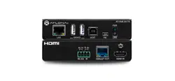
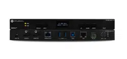
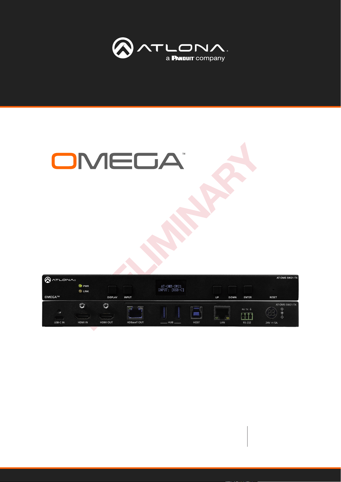
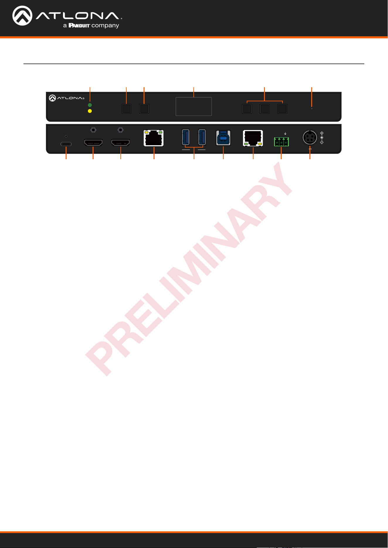
Panel Description
1 PWR and LINK LEDs
Illuminates green when receiving power and amber
when receiving signal.
2 DISPLAY button
Press to activate the display on/o control command.
Each press will toggle between on and o, based o
the display status. (e.g. If the display is on, it will send an
o command.)
3 INPUT button
Use to switch between the USB-C and HDMI inputs.
4 Front Panel Display
Displays current information and menu when
selected.
5 Navigation buttons
Use the navigation buttons to turn on the front panel
display and to navigate through the menu for FW, IP,
RS-232, and input information/set up.
6 Reset button
Press and hold for 5 seconds to reset the IP settings
and username & password to the rst one set. Press
for 15 seconds to factory reset the unit.
7 USB-C IN
Connect a USB-C cable from a USB-C source to this
port. This supports AV, data, and power (when optional
power supply is used).
8 HDMI IN
Connect an HDMI cable from an HDMI source to this
port.
9 HDMI OUT
Connect an HDMI cable from here to an HDMI
display. This port is mirrored with the HDBaseT OUT
port.
10 HDBaseT OUT
Connect a compatible HDBaseT receiver to this
port. This port is mirrored with the HDMI OUT port.
This port can also be used to power the TX when
connected to a compatible receiver. (e.g. AT-OME-
SR21)
11 USB HUB
Connect USB devices to these ports. (e.g. usb
camera, mouse, etc.)
12 HOST USB
Connect to a computer using a USB B to USB A
cable.
13 LAN
Connect an Ethernet cable to this port for control of
the unit and/or to pass Ethernet to a local device.
14 RS-232
Connect a control system to this port for device
control.
15 DC 24V 5A *Optional*
Connect the DC 24V power supply (AT-PS-245-D4
purchased separately) to this port.
DISPLAYOMEGA
TM
INPUT UP DOWN ENTER RESET
PWR
LINK
AT-OME-SW21-TX
AT-OME-SW21-TX
HDMI OUT
HDMI INUSB-C IN
HUBHDBaseT OUT HOST LAN RS-232
RX TX
24V 5A
7
11
8 9 10 12 13 14 15
1 2 3 4 6
5
AT-OME-SW21-TX
8
PRELIMINARY
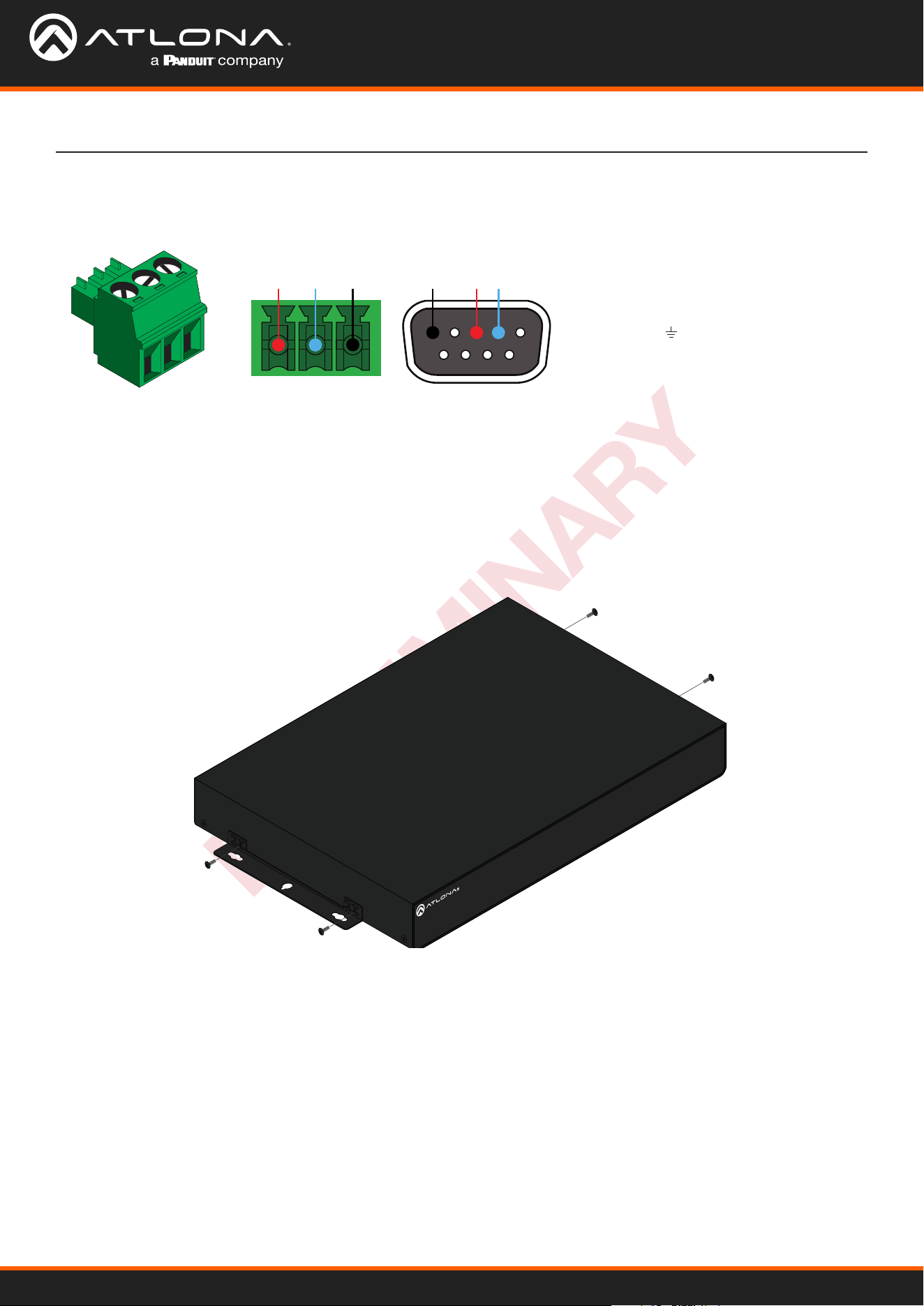
Installation
RS-232 Connection
A 3-pin captive screw connector has been included for RS-232.
Pin out will be determined by the RS-232
cable and connect as RX (receive), TX
(transmit) and (ground).
GND RX
TX
GNDRX TX
Mounting Instructions
The .OME-SW21-TX includes two mounting brackets and four mounting screws, which can be used to attach the unit
to any at surface.
1. Align the mounting bracket to the sides of the unit.
2. Use the included mounting screws to secure the mounting bracket to the enclosure.
3. Repeat the steps for the other side of the unit.
AT-OME-SR21
OUTPUT
LAN DC 24VRELAY
C1 COM C2
HDBaseT IN
L R
+
+
1
IP MODE
RESET RS-232
1 2
RX RXTX TX
2
AT-SKU
AT-OME-SW21-TX
9
PRELIMINARY
Installation
AT-OME-SR21
OUTPUT
LAN DC 24VRELAY
C1 COM C2
HDBaseT IN
L R
+
+
1
IP MODE
RESET RS-232
1 2
RX RXTX TX
2
AT-SKU
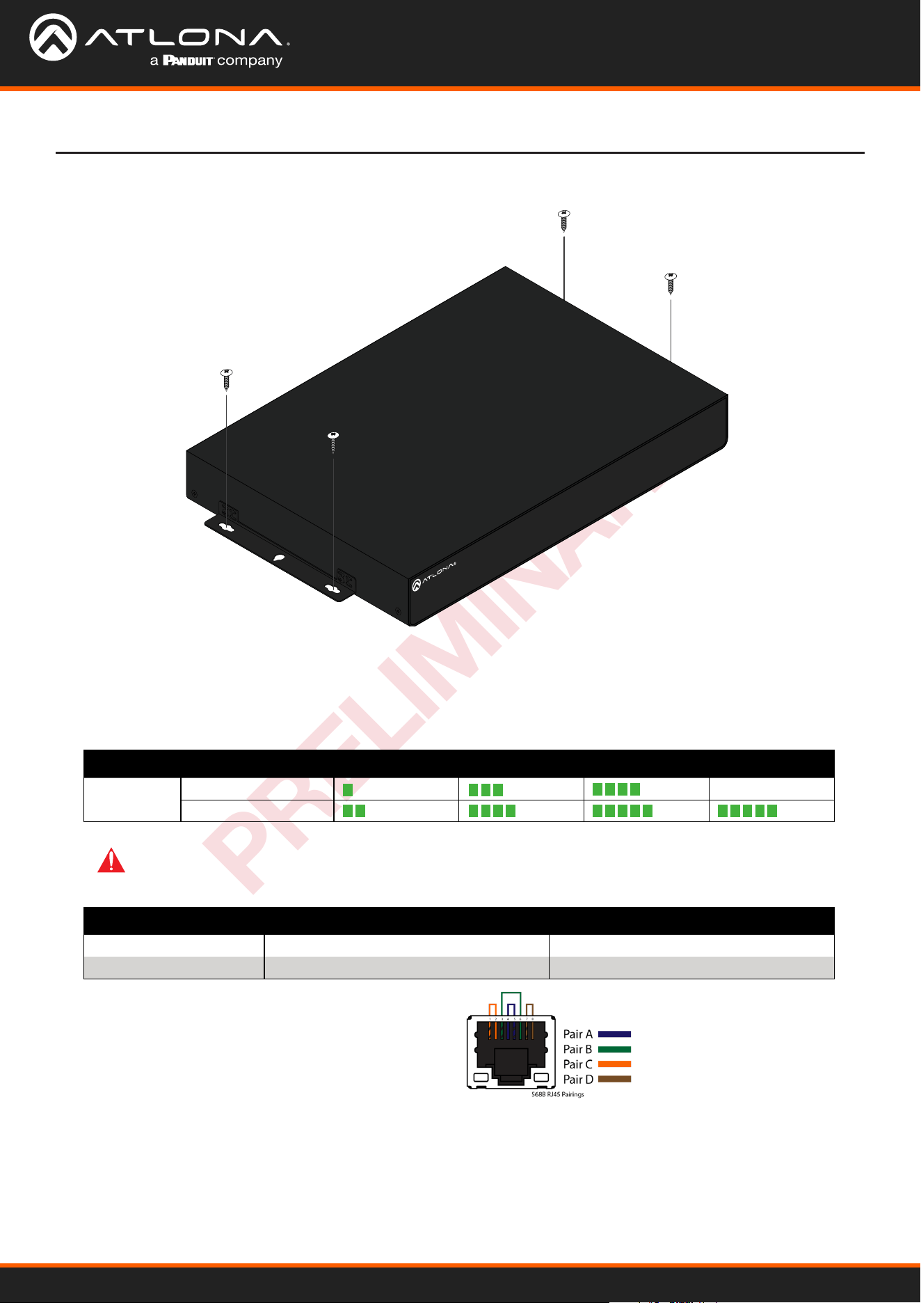
Cable Guidelines
Refer to the tables below for recommended cabling when using Altona products with HDBaseT. The green bars
indicate the signal quality when using each type of cable. Higher-quality signals are represented by more bars.
Use of a TIA/EIA 568B termination
is recommended for optimal
performance.
IMPORTANT: Stranded or patch cables are not recommended due to performance issues. Shielded
cables are strongly recommended to minimize signal noise and interference.
4. Mount the unit using the oval-shaped holes, on each mounting bracket. If using a drywall surface, a #6 drywall
screw is recommended.
Core Shielding CAT5e CAT6 CAT6a CAT7
Solid UTP (unshielded) N/A
STP (sheilded)
Cable Max. Distance @ 4K Max. Distance @ 1080p
CAT5e 295 feet (90 meters) 330 feet (100 meters)
CAT6 / 6a / CAT7 330 feet (100 meters) 330 feet (100 meters)
AT-OME-SW21-TX
10
PRELIMINARY
Installation
Connection Instructions
1. Connect an HDMI source to the HDMI IN port.
2. Connect a USB-C source to the USB-C IN port, using the included cable.
3. Connect an HDMI cable from the output port to an HDMI display.
4. Connect a compatible HDBaseT receiver to the HDBaseT OUT port.
5. *Optional* Connect USB devices (e.g. USB camera) to the USB hub ports.
6. *Optional* Connect the HOST USB port to a computer using a USB B to USB A cable (cable not provided).
7. *Optional* Connect to the 3-pin captive screw RS-232 port to control the display or the unit.
8. *Optional* Connect a network switch to the LAN ports, for IP control, RS-232 control, system conguration, or
Ethernet routing.
9. *Optional* If not being powered by the receiver, connect the DC 24V power supply (AT-PS-245-D4 purchased
through atlona.com) to the power port. When using the optional power supply, the OME-SW21-TX will provide
power to compatible receivers (e.g. AT-OME-EX-RX) and 60W power to compatible USB-C devices.
NOTE: With the current limitations of HDBaseT, USB signals can only cascade through 5 hub tiers (6 total
hubs allowed).
NOTE: It is recommended to connect the power supply to the OME-SW21-TX or the compatible receiver,
but not both.

AT-OME-SW21-TX
11
PRELIMINARY
Installation
IP Modes
If no DHCP server is available, or a static IP is required, the OME-SW21-TX can be set to static IP mode using the
front panel OSD menu.
• If no DHCP network is found, it will auto-assign an IP, but using the front panel buttons, it can be set to a static
IP. The unit will auto-assign to:
IP address: 169.254.8.50
Subnet mask: 255.0.0.0
• To switch to static IP mode, use the following button presses:
Static
• Static IP will now be set to:
IP address: 192.168.1.254
Subnet mask: 255.255.0.0
Gateway: 192.168.1.1
• If no DHCP network is found, it will auto-assign an IP:
IP address: 169.254.8.50
Subnet mask: 255.0.0.0
DHCP
By default, the AT-OME-SW21-TX is set to DHCP mode. In this mode, when the AT-OME-SW21-TX is connected to
the Local Area Network (LAN), it will automatically be assigned an IP address by the DHCP server (if available). The IP
address can be seen on the front panel OSD.
ENTERENTER
ENTER
ENTERDOWN
DOWN
AT-OME-SW21-TX
Input: [USB-C]
Setting
[ RS232 BAUD ]
IP MODE
IP RESET
Setting
RS232 BAUD
[ IP MODE ]
IP RESET
IP Mode
[ *DHCP ]
Static
Back
IP Mode
*DHCP
[ Static ]
Back
IP Mode
DHCP
[ *Static ]
Back
AT-OME-SW21-TX
12
PRELIMINARY
Installation
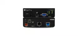
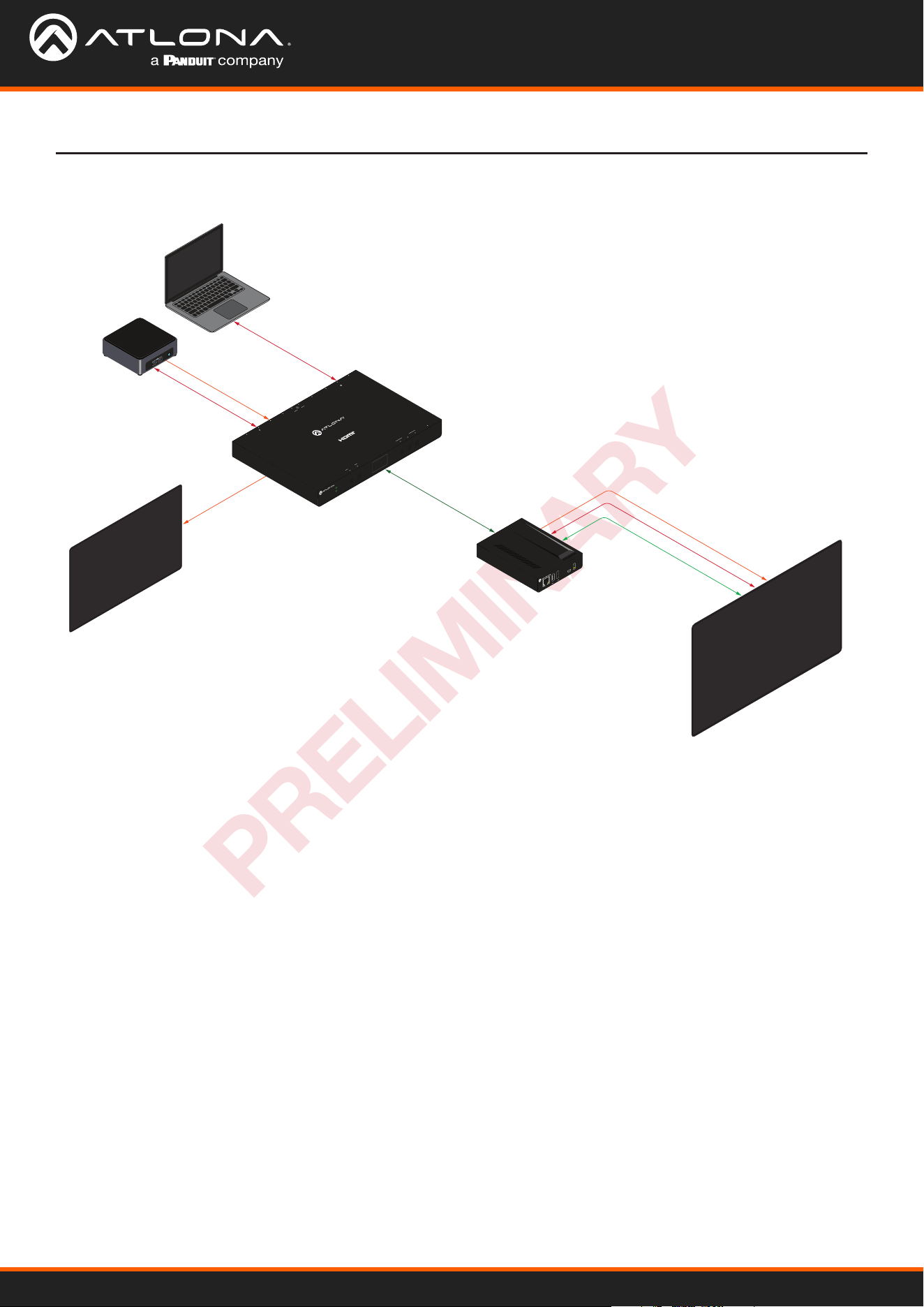
Connection Diagram
HDMI
Laptop
PC
AT-OME-SW21-TX
AT-OME-EX-RX
Interactive Display
Confidence Monitor
HDBaseT
Ethernet
USB
HDMI
USB-C
USB
HDMI
USB
USB
LAN FW
OMEGA
TM
DEVICE
PWR
LINK
AT-OME-SW21-TX
HDMI OUT
HDMI INUSB-C IN HUBHDBaseT OUT HOST LAN RS-232
RX TX
24V 5A
AT-OME-SW21-TX
Omega
™
4K/UHD Switching Transmitter
with USB over HDBaseT
DISPLAY
BUTTON
INPUT UP DOWN ENTER
RESET
HDMI OUTHDMI IN
HUB RS-232HOST LAN PWRUSB-C IN HDBaseT OUT
RX TX
BUTTON
DISPLAY
OMEGA
TM
INPUT UP DOWN ENTER RESET
PWR
LINK
AT-OME-SW21-TX
AT-OME-SW21-TX
13
PRELIMINARY
Control
Front Panel
CEC
RS-232
TCP/IP
Web Server
RS-232 control for connected devices and the unit are available through the RS-232 captive screw connection. The
commands can be found within the API at https://atlona.com/pdf/AT-OME-SW21-TX_API.pdf .
TCP/IP control for connected devices and the unit are available through the LAN connection. The commands can be
found within the API at https://atlona.com/pdf/AT-OME-SW21-TX_API.pdf.
The unit has a built in Web Server that will allow for unit conguration and device control. See the Web Server section
for more information.
The unit has a front panel display and buttons to view and set up basic settings. See the Front Panel section for more
information.
The product has CEC display control over HDMI. More information can be found in the CEC Web Server section.

AT-OME-SW21-TX
14
PRELIMINARY
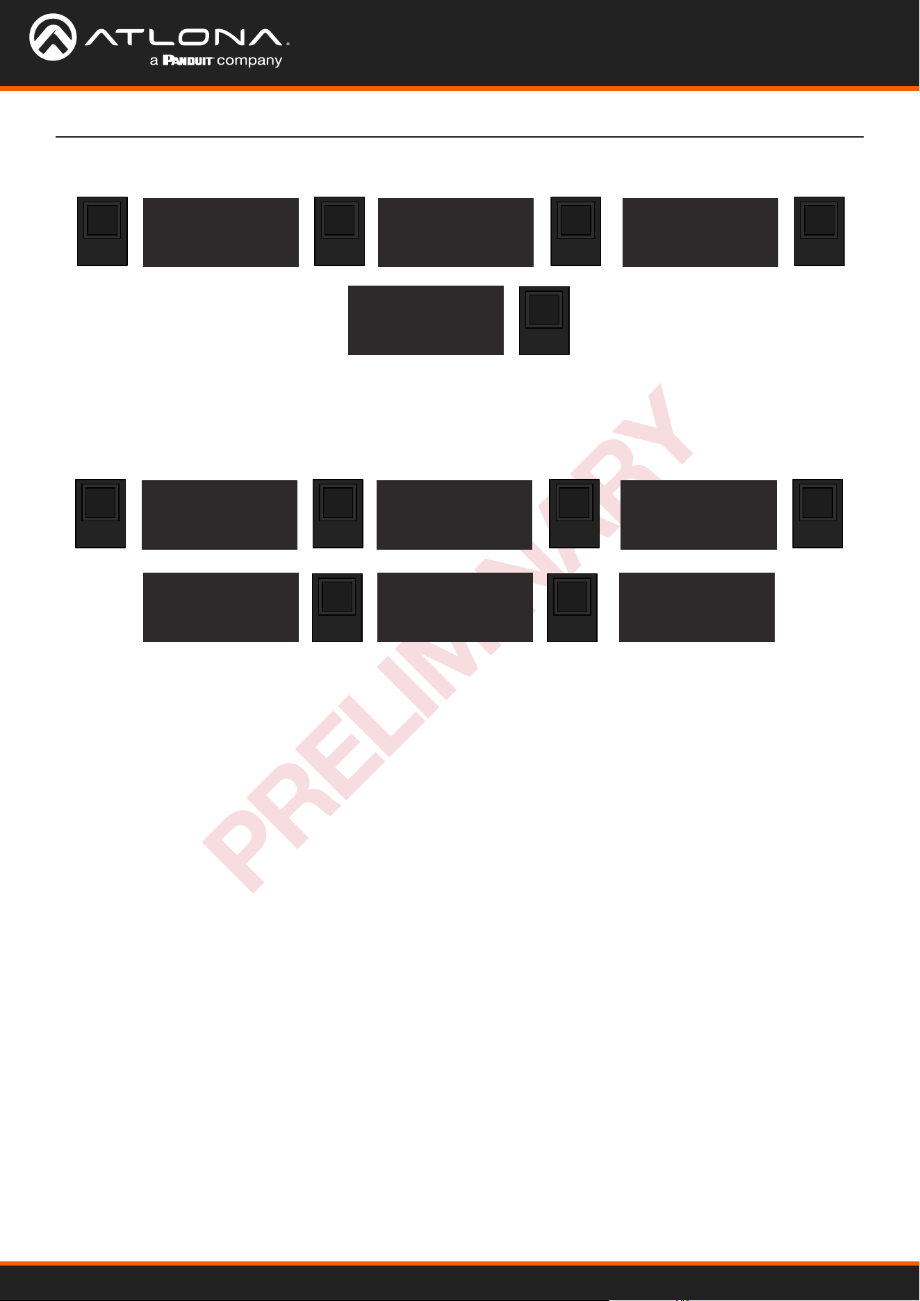
Front Panel
The unit has a front panel display and buttons to view and set up basic settings. Any button can awaken the front
panel, but to avoid triggering secondary functions, it is recommended to use the ENTER button. At any time during
use, the BACK button can be used to navigate to previous menu options.
The front panel display will provide input, rmware (FW), MAC address, IP, and all input statuses. Use the following
button presses to view them:
To view and change the Input, use the following buttons:
The current baud rate can be viewed and changed using the following button presses:
The IP can be switched between DHCP and Static mode using the following button sequence:
or
UP UP
UP
UP
ENTERENTER
ENTER
ENTER
ENTER
ENTER
DOWN
DOWN
INPUT
AT-OME-SW21-TX
Input: [USB-C]
MAC ADD
B898B00XXXXX
AT-OME-SW21-TX
Input: [USB-C]
AT-OME-SW21-TX
Input: [USB-C]
AT-OME-SW21-TX
Input: [HDMI]
Setting
[ RS232 BAUD ]
IP MODE
IP RESET
RS232 BAUD
[ *115200 ]
57600
38400
RS232 BAUD
19200
[ 9600 ]
back
RS232 BAUD
19200
[ *9600 ]
back
IP MODE: DHCP
XXX.XXX.X.XX
255.255.255.0
XXX.XXX.X.1
INPUT STATUS
NONE
NONE
NONE
FW info
ARM : V#.#.#.#
USBC : V#.#.#
VALENS: V#.#.#
Settings
Input Selection
RS-232 Settings
IP Settings
ENTERENTER
ENTER
ENTERDOWN
DOWN
AT-OME-SW21-TX
Input: [USB-C]
Setting
[ RS232 BAUD ]
IP MODE
IP RESET
Setting
RS232 BAUD
[ IP MODE ]
IP RESET
IP Mode
[ *DHCP ]
Static
Back
IP Mode
*DHCP
[ Static ]
Back
IP Mode
DHCP
[ *Static ]
Back
AT-OME-SW21-TX
15
PRELIMINARY
Front Panel
ENTERENTER
ENTER
ENTERDOWN
AT-OME-SW21-TX
Input: [USB-C]
Setting
[ RS232 BAUD ]
IP MODE
IP RESET
Setting
RS232 BAUD
IP MODE
[ IP RESET ]
IP reset
[ yes
back
ENTERENTER
ENTER
ENTERDOWN
DOWN
AT-OME-SW21-TX
Input: [USB-C]
Setting
[ RS232 BAUD ]
IP MODE
IP RESET
Setting
ip mode
IP reset
[ OSD OFF ]
OSD OFF
[ NEVER ]
5s
10s
OSD Off
*20s
[ 30s ]
Back
OSD off
20s
[ *30s ]
Back
To reset the IP of the unit, use the following steps:
To conserve the front panel display, the unit has a default timer of 30 seconds before it is turned o. To set the
display to a dierent timer, use the below button sequence:
Front Panel Display Timer
AT-OME-SW21-TX
16
PRELIMINARY
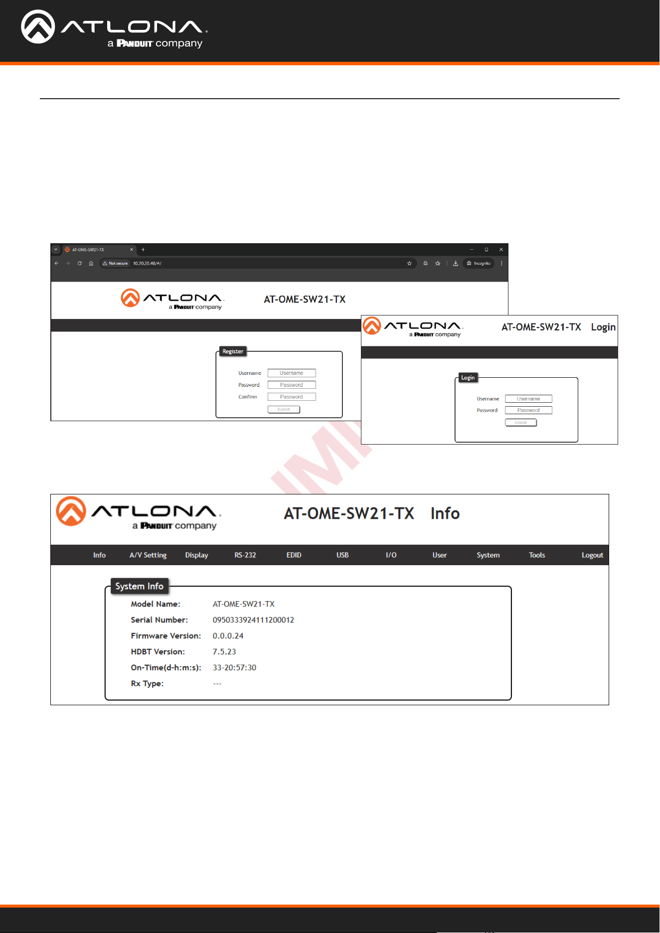
Web Server
The OME-SW21-TX includes a built-in webGUI, which allows easy remote management and control of all features.
Follow the instructions below to access the webGUI.
1. Make sure that an Ethernet cable is connected between the LAN port on the OME-SW21-TX and the network.
2. Find the IP address of the unit from the front panel or by scanning the network.
3. Launch a web browser and enter the IP address in the address bar.
4. The AT-OME-SW21-TX Register page will be displayed.
5. Create a Username and Password, then press the Submit button.
6. Once the username and password are created, log into the webGUI. The info page will open, providing the
general information of the AT-OME-SW21-TX.
AT-OME-SW21-TX
17
PRELIMINARY
Web Server
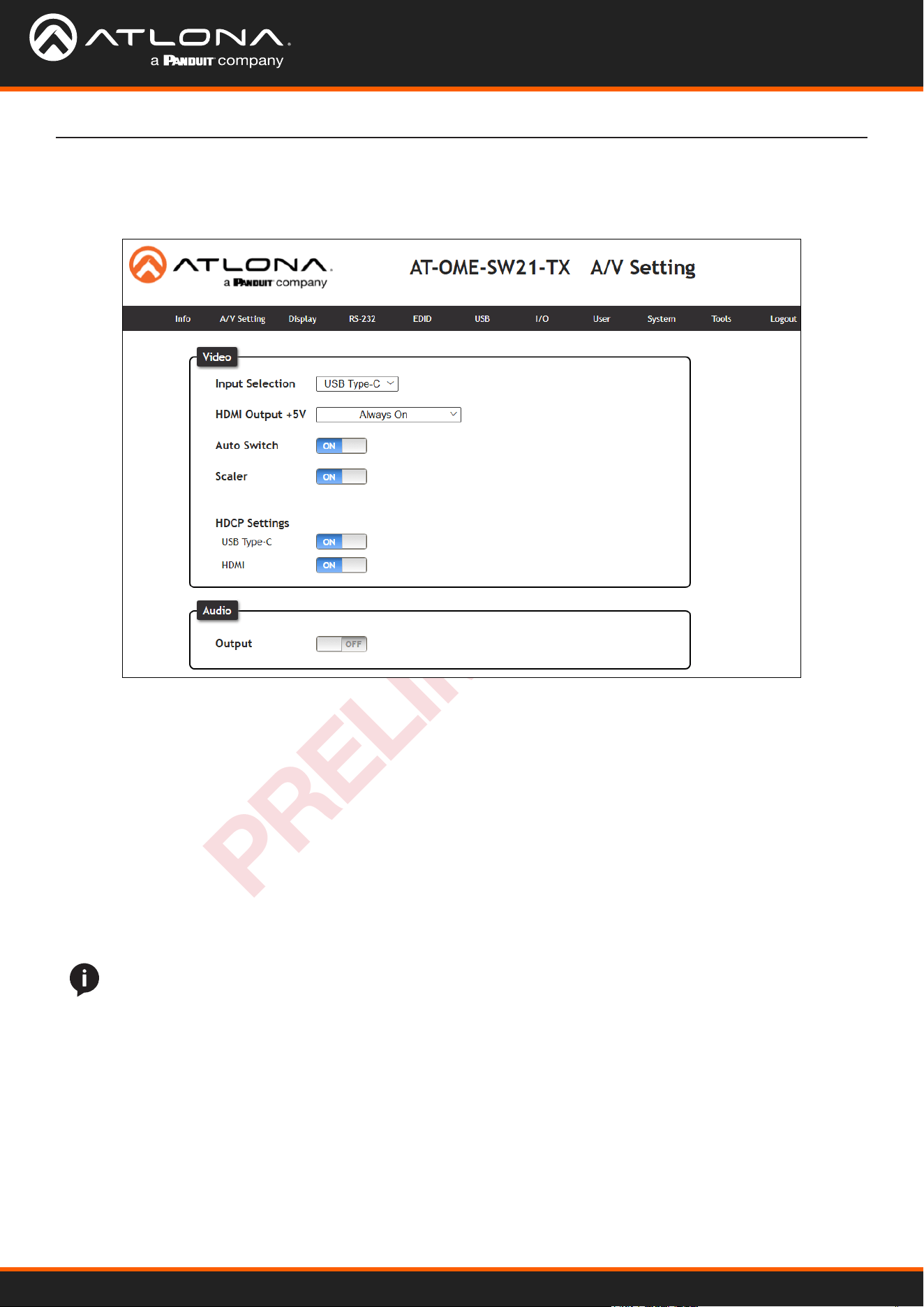
Select A/V Settings from the top navigation to adjust routing and video settings.
AV Settings
Video
Input Selection - Use the drop-down menu to switch USB Type-C or HDMI inputs.
HDMI Output +5V - When set to Always On, it will keep the 5V pin on the HDMI output port live. When set to
On When Signal Present, it will only send the 5V hot plug when receiving an input signal.
Auto Switch - Set switching to on, to have the source change when a new signal is detected or the current
source is no longer sending signal.
Scaler - When enabled, the OME-SW21-TX will downscale the signal output to 1080p.
HDCP Settings
On - Sets the HDCP of the port to ON, allowing HDCP to switch between compliant and non-compliant ac-
cording to the source and display HDCP handshake status.
O - Sets the port to HDCP non-compliant. No HDCP compliant source signals will pass in this mode.
Audio
Output - When set to on, the audio will be muted. When set to o (default), the audio will be unmuted.
NOTE: Some sources ag all content as protected, by selecting HDCP o the source device may send
only user created content. In some cases, the source must be congured to send content to non-HDCP
devices (e.g. HDCP must be turned o to pass macOS or Windows content to a non-HDCP display).
NOTE: Setting HDCP to OFF will not remove HDCP, it will simply tell the source to send non-HDCP
content.
AT-OME-SW21-TX
18
PRELIMINARY
Web Server
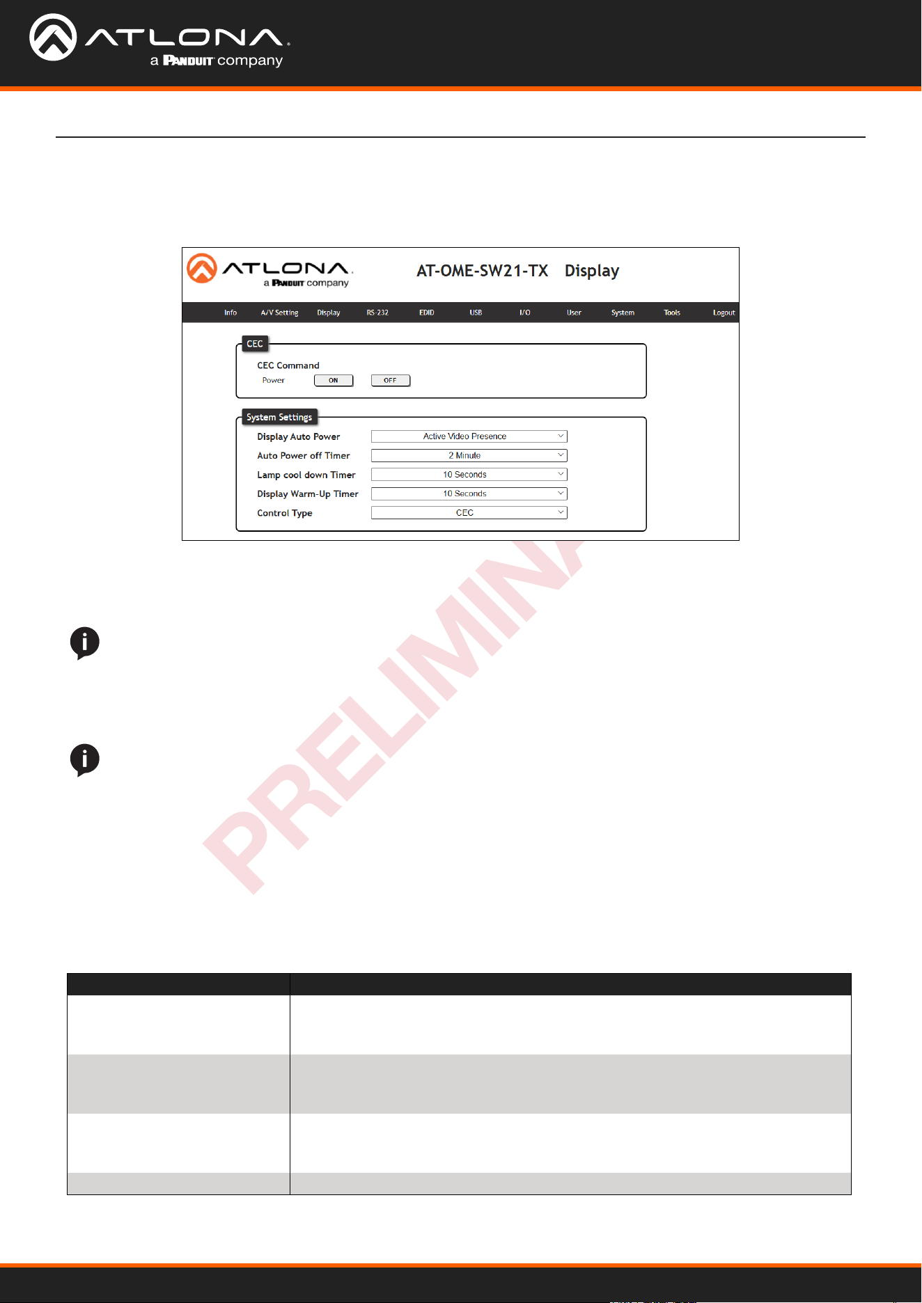
System Settings
Display Auto Power - Enable to set the display to power o when the power settings are met. The display will
automatically turn on as soon as a signal is received and all timers have expired.
Auto Power o timer - Sets the time between when the last signal was received and the display power o
command is sent. Time range is from 15 seconds up to 15 minutes.
Lamp cool down timer - Sets the time between when the display is turned o and when the next command can
be sent. Time range is from 10 seconds up to 300 seconds.
Display Warm-Up Timer - Sets the amount of time between when the display is turned on to when the unit
sends any commands. Time range is from 10 seconds up to 300 seconds.
Control Type - Selects which command type is used to send commands and what type of control signal is sent
when the command is triggered. Options are CEC, TCP/IP or RS-232.
CEC
Power - Press to send the CEC power on or o command out through the HDMI port of the connected
receiver.
Select Display from the top navigation to adjust display control settings.
Display
NOTE: Defaults are set to turn the display o after 15 seconds of signal loss and to wait 10 seconds before
any more commands are sent to the display.
NOTE: When connected to a compatible receiver (e.g. AT-OME-MS42-HDBT) with display control, all the
system settings will be controlled through the receiver and not display on the OME-SW21-TX.
Modes Description
Active Video Presence Device will send the power o command to the display if no active source
is detected on the input, and power on command when an active source is
detected. Power timers will be followed.
Active Video Presence
w/Occupancy Sensor*
When the occupancy sensor (AT-OCS-900N) is triggered and source signal is
active or inactive, it will send the on or o command based on physical and
signal presence.
Occupancy Sensor only Power on and o commands will be sent based on the OCS-900N sensor
status. The sensor must be connected to the same network as the OME-SW21-
TX and connected on the I/O page.
Disabled No display control
AT-OME-SW21-TX
19
PRELIMINARY
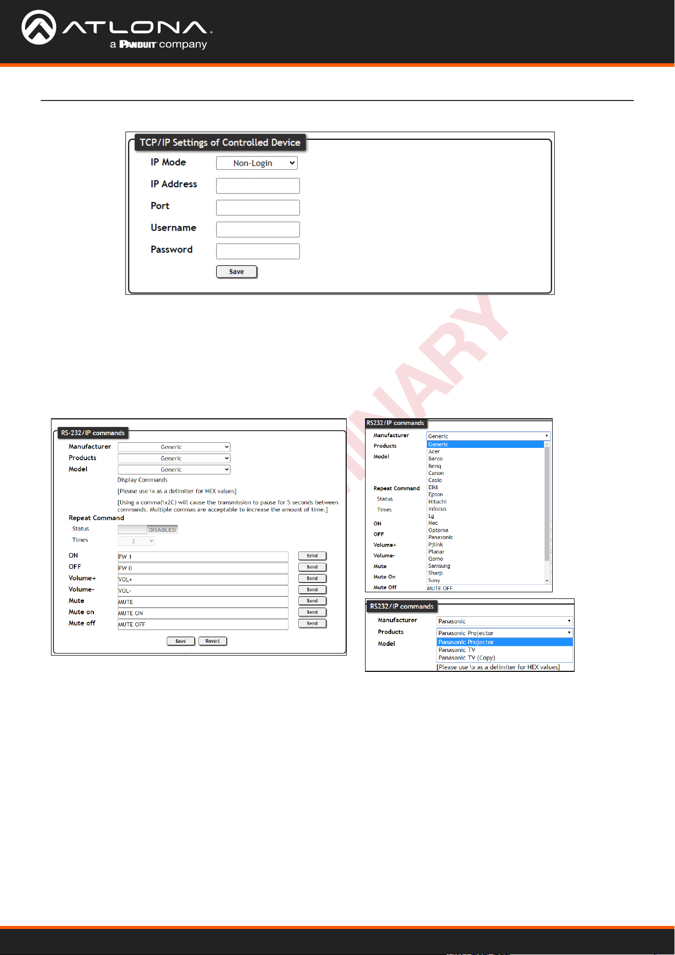
Web Server
TCP/IP Settings of Controlled Device (only available when IP is selected)
IP Mode - Toggle login mode between Non-Login and Login. If set to Login, a username and password will be
required to control the controlled device via TCP/IP.
IP Address - Sets to the IP of the controlled device/display.
TCP/IP Port - Set the TCP/IP port of the controlled device for control.
Username & Password - Sets the username and password that is required when login mode is enabled.
RS-232 / IP Commands
Manufacturer, Products, Models - Select the make and model of the display for control. Commands have been
programmed into the unit for a wide range of products. If the current display is not found within the database,
use Generic and manually adjust the command elds.
Repeat Command - Enable Status to repeat the commands. Default repeat number is 2 and can be adjusted
from 2 to 4 times.
Commands: On/O/Volume/Mute - These elds will automatically be lled with the correct command when
selecting a manufacturer and product from the drop-down menus. If manually entering the commands, type
them into the elds next to the command name.
Send - Use this button to send the command to the display. This can be used while manually typing the
commands to ensure the commands are correct.
Save - Save the commands to the webGUI. Manufacturer, Products, and Model will revert to Generic but the
commands will be saved from the previously selected and saved Manufacturer, Products, and Model selection.
Revert - Sets the commands back to the previously saved settings.
AT-OME-SW21-TX
20
PRELIMINARY
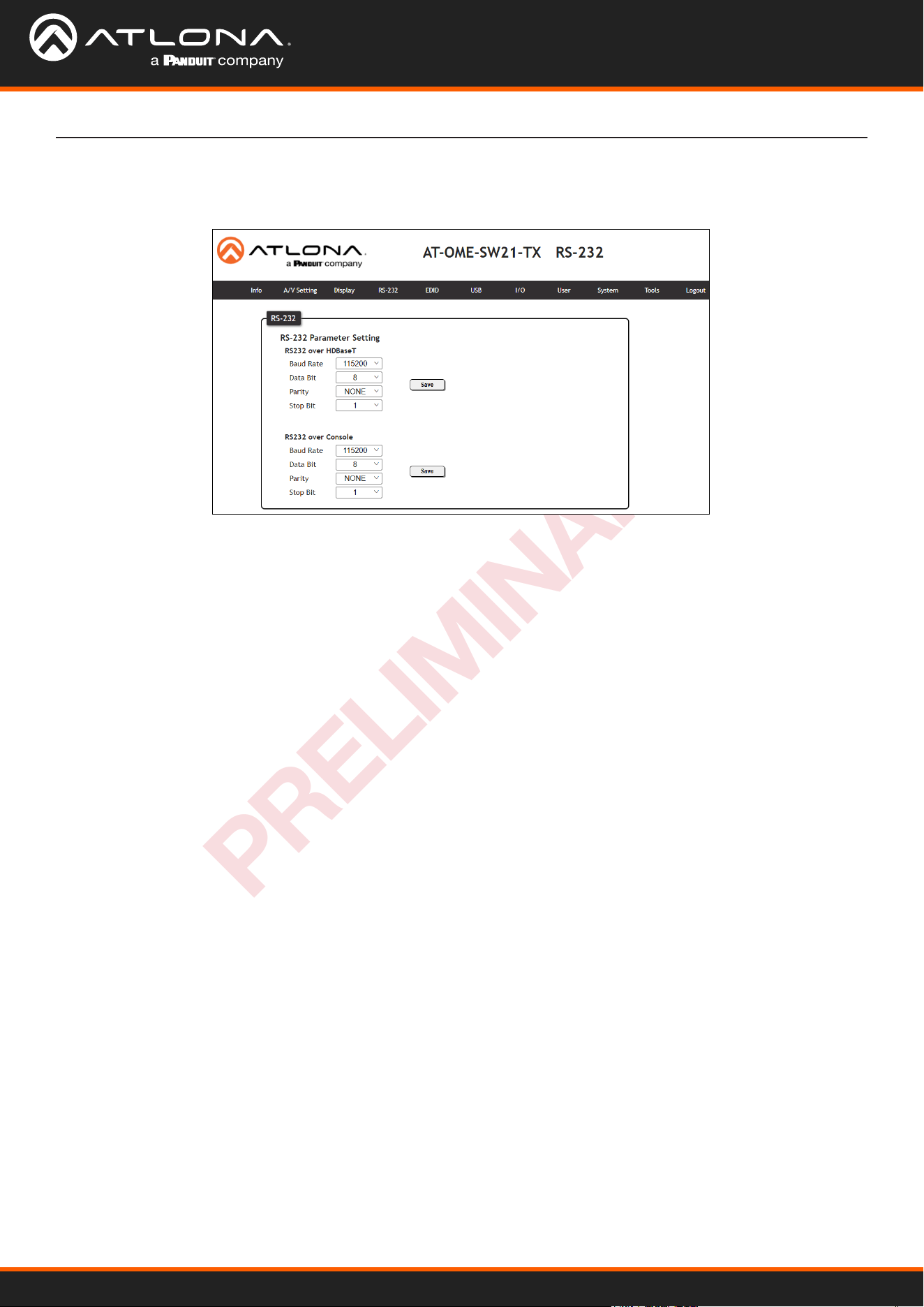
RS-232 Parameter Setting
RS232 over HDBaseT - Select the baud rate, data bit, parity, and stop bit to match the receiver’s parameters.
Defaults are 115200, 8, None, and 1.
RS232 over console - Select the baud rate, data bit, parity, and stop bit to match the OME-SW21-TX’s
parameters. Defaults are 115200, 8, None, and 1.
Select RS-232 from the top navigation to adjust the zone control parameters for the RS-232 port.
RS-232
Web Server
AT-OME-SW21-TX
21
PRELIMINARY
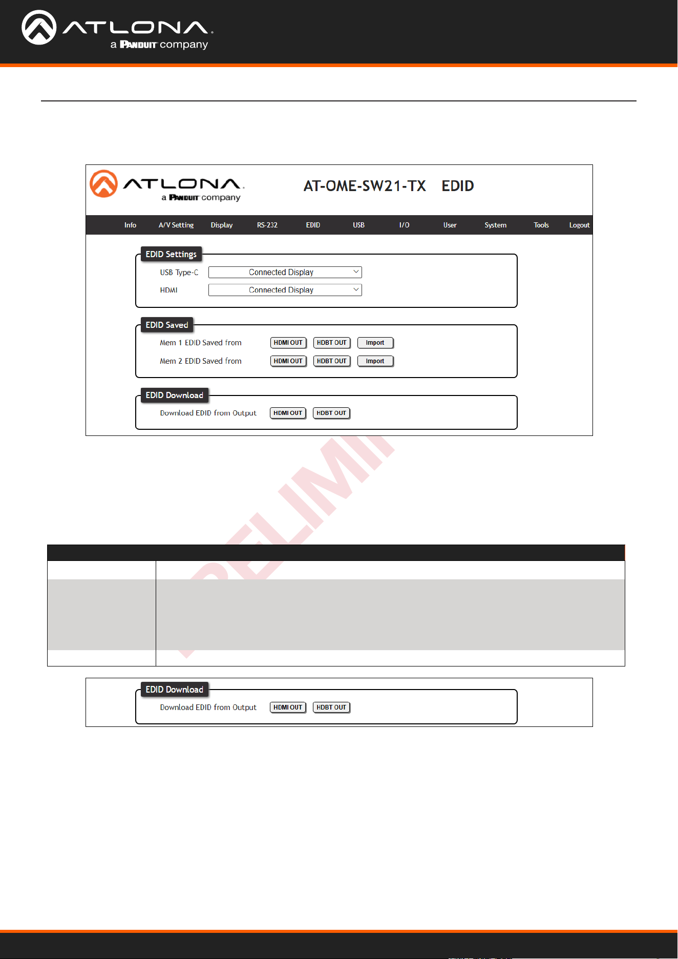
Select EDID from the top navigation to save/load EDIDs.
EDID
EDID
EDID Settings - Use the drop down menu to select from default (highest common resolution between source
and display), 9 internal EDIDs, and 2 previously saved EDIDs.
EDID Saved - Select the HDMI OUT or HDBT OUT to save to EDID memory slot. An external EDID can also be
imported using the Import button and a locally saved le. Once saved or imported, it can be selected from the
EDID Settings drop down menus.
EDID Download - Select the Output and the EDID will be downloaded to the local computer.
EDID Selections
Connected Display Chooses the highest common resolution between source and display
Internal 3840x2160@60 2CH HDR PCM
3840x2160@30 2CH SDR PCM
3440x1440@50 2CH SDR PCM
2560x1080@60 2CH SDR PCM
1920x1200 2CH SDR PCM
1920x1080P@60 2CH SDR PCM
1920x1080P@30 2CH SDR PCM
1280x720P@60 2CH SDR PCM
1280x800 2CH SDR PCM
Saved 2 Memory slots
Web Server
AT-OME-SW21-TX
22
PRELIMINARY
Web Server
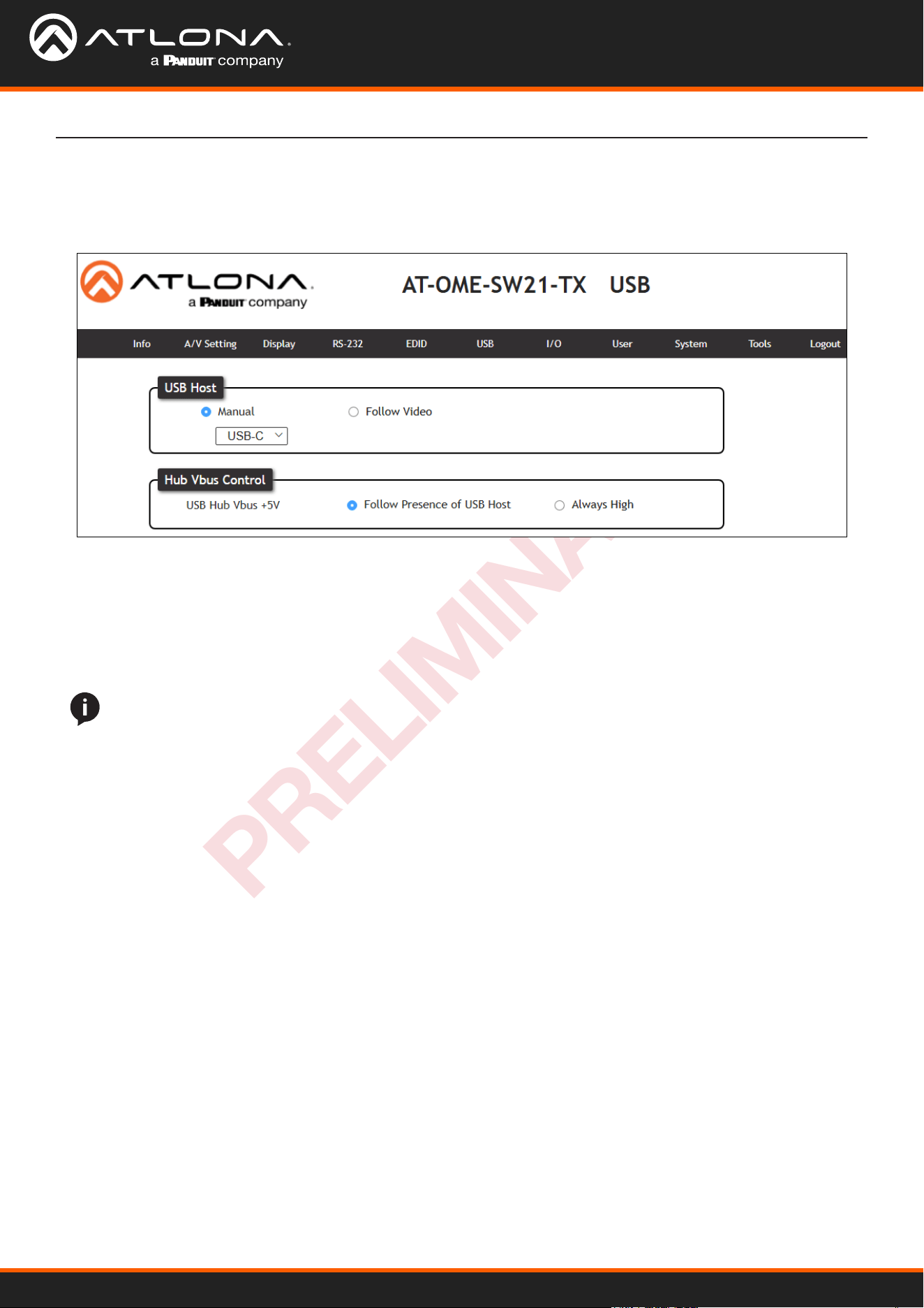
Select USB from the top navigation for USB routing.
USB
USB Host
Manual - Select which host will be used. Select between USB-C, the local USB Host (USB 1), or the connected
receiver’s USB Host (remote).
Follow Video (default) - Sets the USB hosts to follow the video input selection. If a video input on the transmitter
is selected, the USB will switch to the transmitter’s host ports. If the USB-C source is selected, it will use the
USB-C as host. If a source on the receiver is selected, it will switch to the receiver’s host port.
Hub Vbus Control (USB Hub Vbus +5V)
Follow Presence of USB Host (default)- When selected, the USB hubs will toggle on and o based o the activity
of the USB host.
Always High - When chosen, keeps the 5V pin of USB ports on, even when no host is connected. This will allow
devices (e.g. USB MIC) to keep charging when no host is present.
NOTE: Whenever the USB Host mode is changed, the HDBaseT link will reset. The reset can take up to 20
seconds before full operation resumes.
AT-OME-SW21-TX
23
PRELIMINARY
Web Server
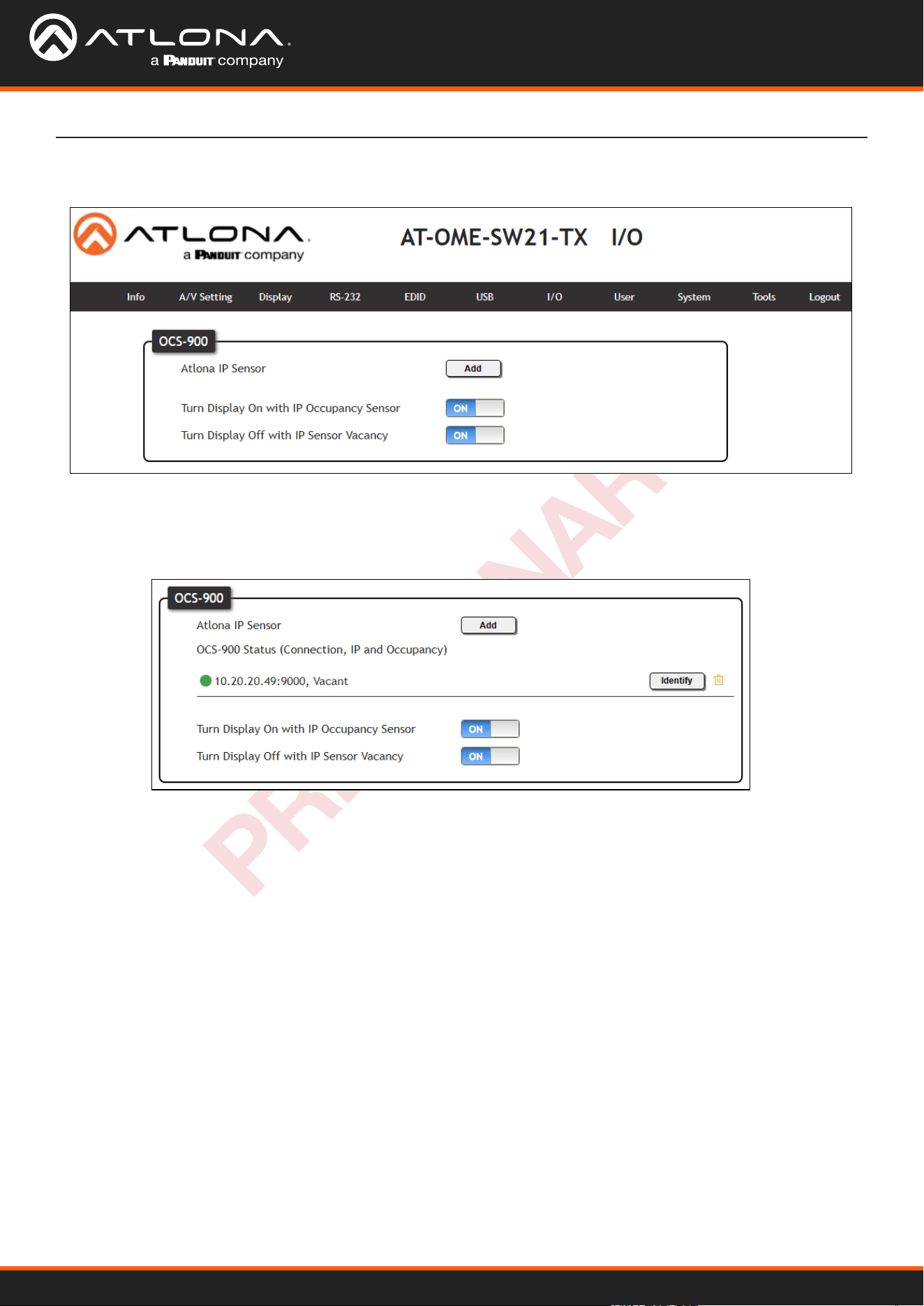
I/O
OCS-900
Atlona IP Sensor - Select the Add button. A pop up will appear. Fill in the IP address of the OCS-900N sensor
and press Add. The Sensor will be added to the page. Multiple OCS-900Ns can be added to the room using
the same steps.
Turn Display On with IP Occupancy Sensor - When enabled, the display will turn on when the OCS-900N senses
an occupant.
Turn Display On with IP Occupancy Sensor - When enabled, the display will turn o when the OCS-900N signals
the room has been vacated.
AT-OME-SW21-TX
24
PRELIMINARY
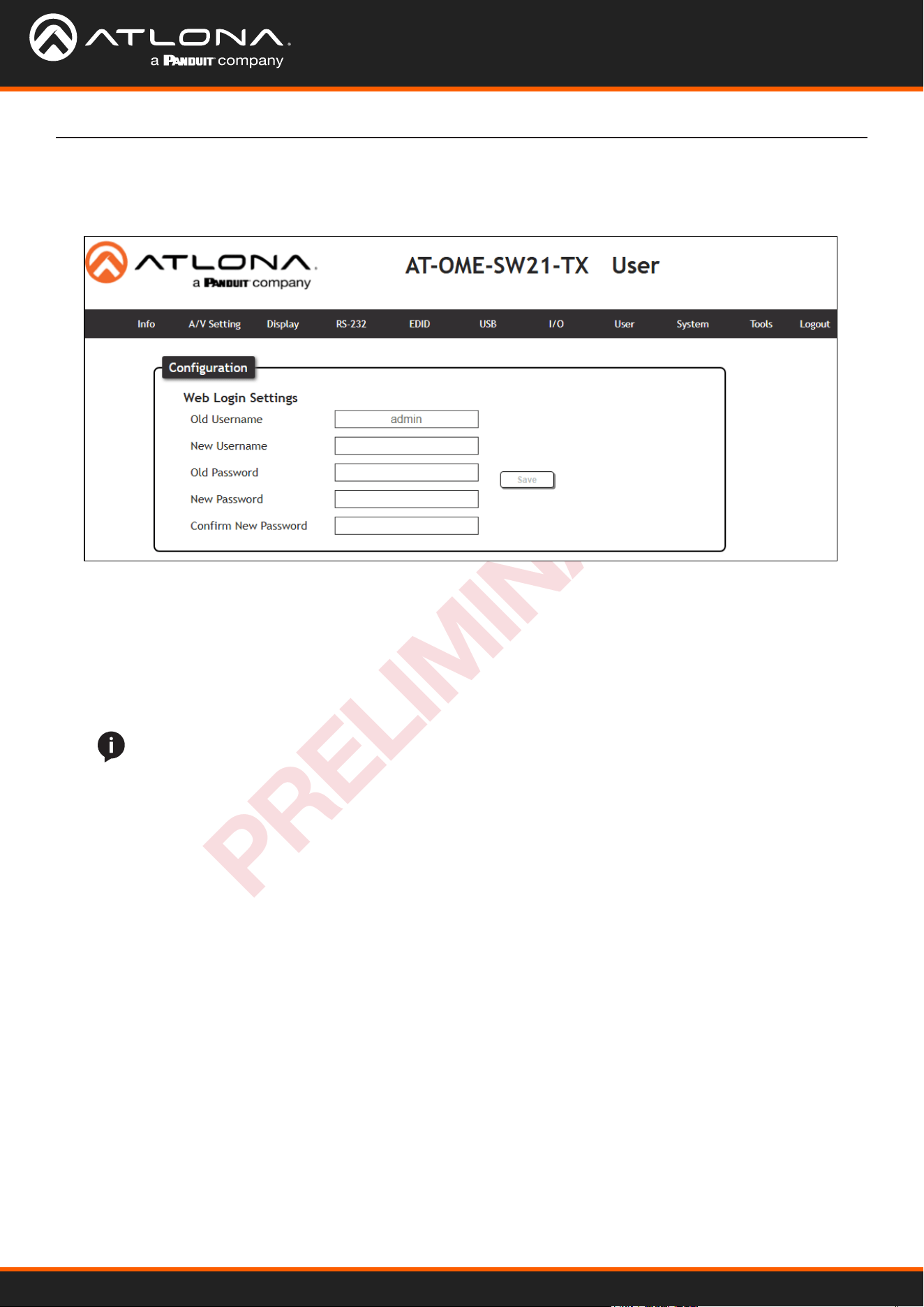
Select Cong from the top navigation to update the admin password.
User
Web Server
User
Old Username - Type in the current username of the OME-SW21-TX.
New Username - Update the username for the unit.
Old Password - Type in the current password of the device.
New Password - Enter a new password.
Conrm New Password - Reenter the new password for verication.
Once the new username and password have been entered, press the Save button to make it live. The user will
be logged out and must log back in with the new username and password.
NOTE: The passwords cannot contain any special characters. e.g. !@#$%/^&*\?+-;’”.
AT-OME-SW21-TX
25
PRELIMINARY
Web Server
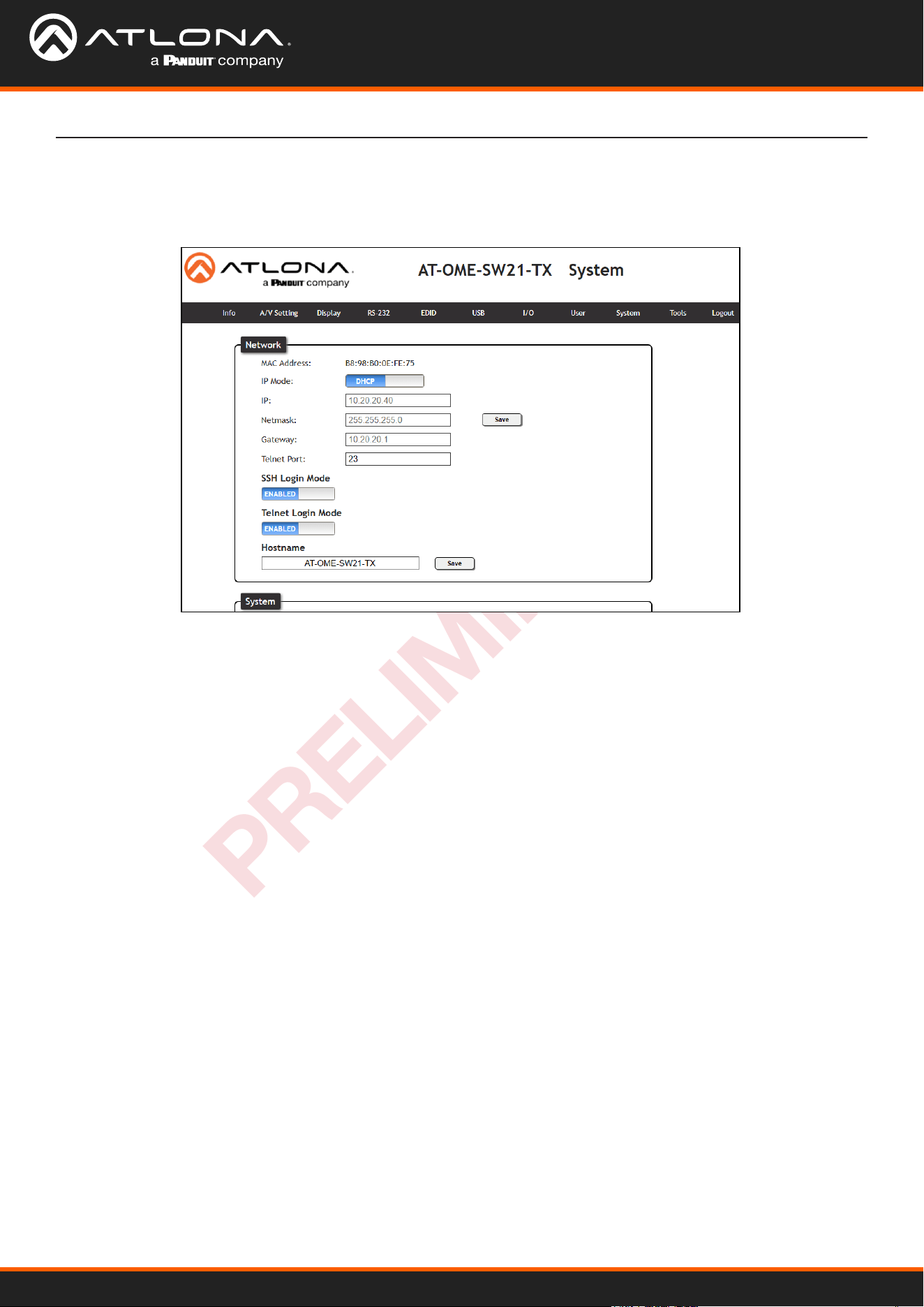
Select System from the top navigation to adjust relay, network, or system options.
System
Network
MAC Address - Displays the MAC address of the unit.
IP Mode - Switch between static and DHCP IP modes.
IP, Netmask, Gateway - This will display the unit’s current DHCP IP settings. When set to static, ll in the IP
address, netmask, and gateway.
Telnet Port - Set the telnet port if needed for control. Default port is 23.
SSH Login Mode - Enable or disable SSH Login Mode functionality by toggling this switch.
Telnet Login Mode - Enable or disable Telnet functionality by toggling this switch.
Hostname - Set the name of the unit. This will display in network discovery.
AT-OME-SW21-TX
26
PRELIMINARY
Web Server
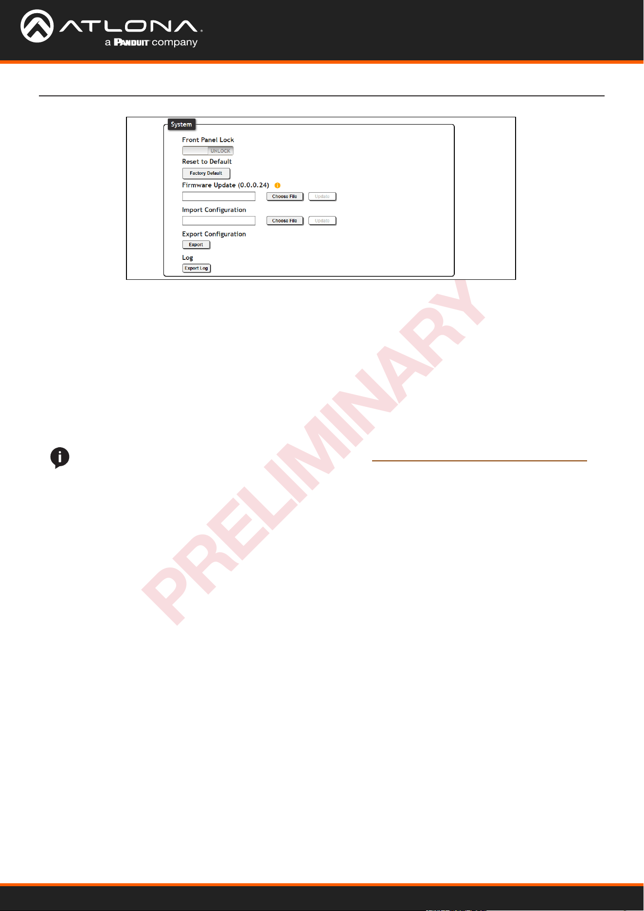
NOTE: Firmware updates and release notes can be found at https://atlona.com/product/at-ome-sw21-tx/ .
System
Front Panel Lock - Lock or unlock the front panel buttons.
Reset to Default- Press the Factory Default button to set the unit back to all factory settings, including IP mode.
Firmware Update - Use the choose le button to search the local PC for the rmware le. Once selected, press
the Update button to start the rmware update.
Import Conguration - Select the Choose File button to select the conguration le o the local computer. Once
selected, press the Upload button to push the new conguration to the unit.
Export Conguration - Press the Download button to save the unit’s conguration to the local computer.
Log - Use the Export Log button to download the OME-SW21-TX’s log to a local PC.
AT-OME-SW21-TX
27
PRELIMINARY
Web Server
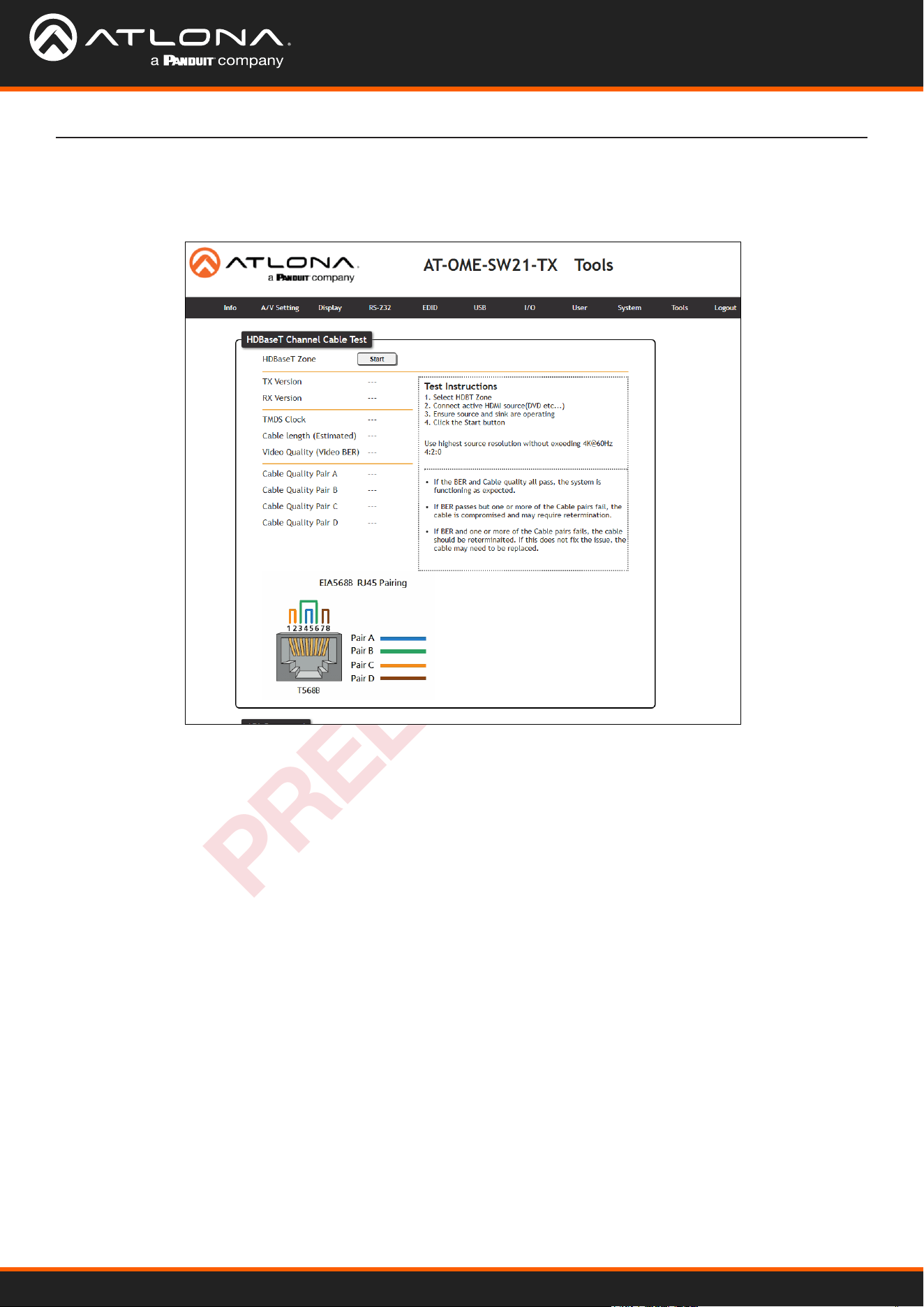
Select Tools to open the HDBaseT cable test and API command eld page. The HDBaseT test will check extender
versions, cable status and length, and Video Quality.
Tools
HDBaseT Channel Cable Test
HDBaseT Zone - Use the start/stop button to run or cancel the HDBaseT signal testing. The webGUI will remain
active until the testing stops.
TX / RX Version - When the test starts, the chipset version will display. e.g. AT-OME-SR21 (RX) will be VS2310.
TMDS Clock - After the test has been initiated, it will display the TMDS clock frequenzy in Mhz.
Cable Length - An approximate HDBaseT cable length will be displayed here after the test has been started.
Video Quality (Video BER) - Will display Pass or Fail depending on if the cable video signal quality.
Cable Quality - Each pair will be tested and return a Pass or Fail status.
Failure:
One or more Pairs - Reterminate the cable.
Of BER and any pairs - Replace the cable.
Of one or more pairs after retermination - Replace the cable.
AT-OME-SW21-TX
28
PRELIMINARY
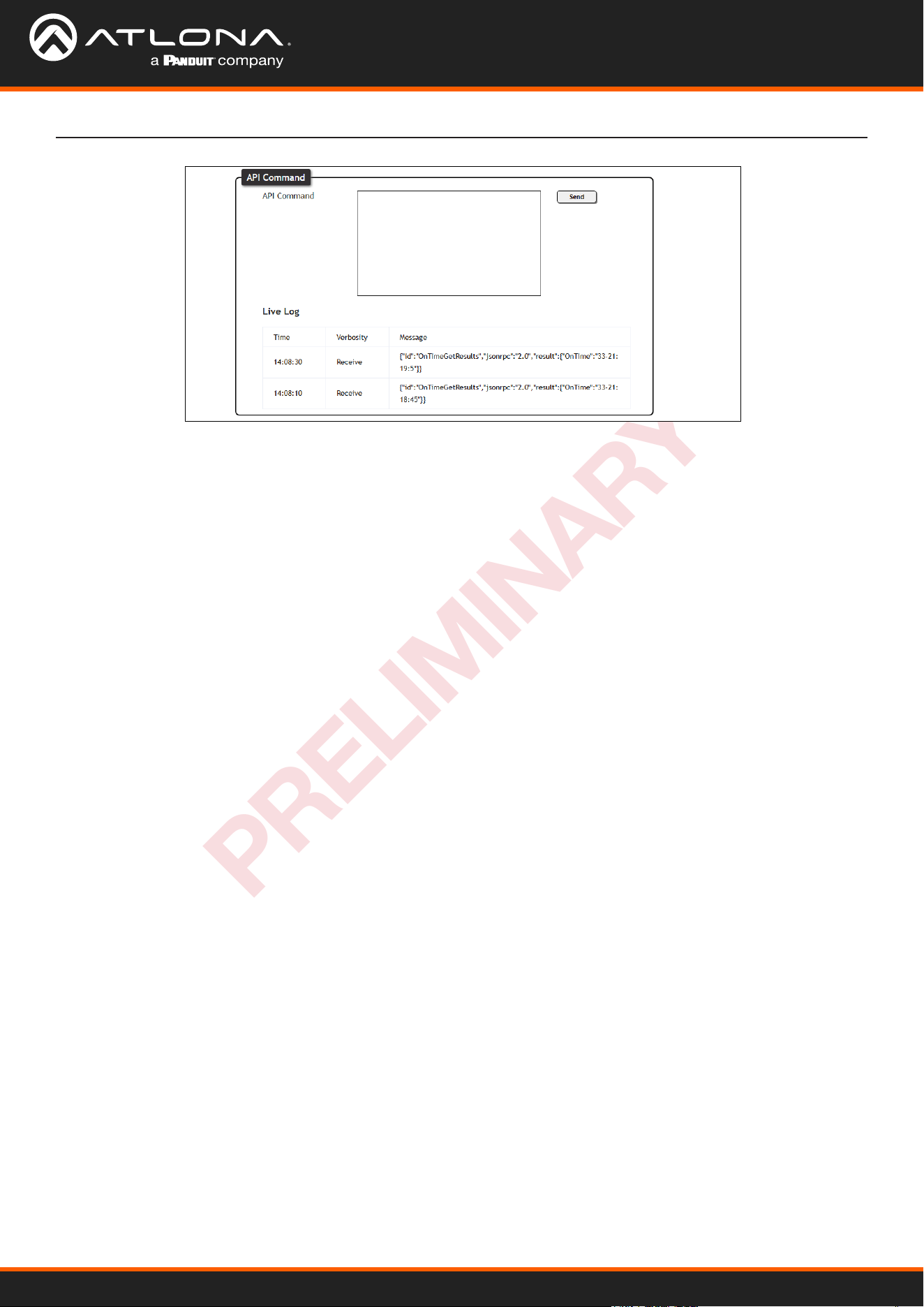
Web Server
API Command
API Command - Commands can be entered here to be sent to the unit.
Send - Press this button to transmit the command to the unit.
Log - This will display a command log of any and all commands sent.
AT-OME-SW21-TX
29
PRELIMINARY
Appendix
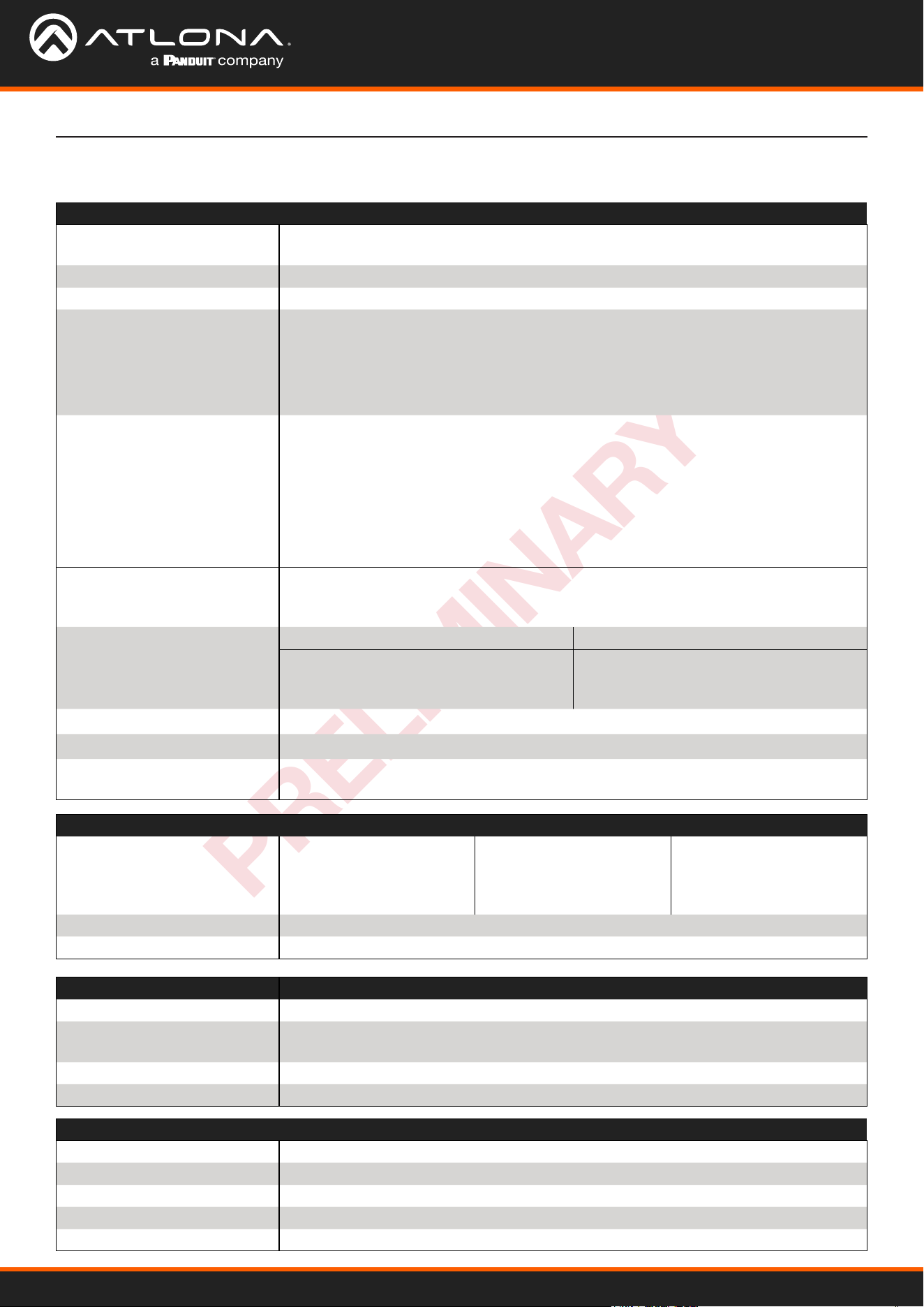
Specications
Video
Signal Type Input - DisplayPort Alternate Mode (USB-C), HDMI
Output - HDBaseT, HDMI
Copy Protection HDCP 1.4/2.2/2.3
Pixel Clock 600MHz (300MHz over HDBaseT)
UHD/HD/SD 4096×2160(DCI)@60/50/30/25/24Hz
3840×2160(UHD)@60/50/30/25/24Hz
2560x1440@30Hz
1920x1080p@60/59.94/50/30/29.97/25
/24/23.98Hz
1920x1080i@30/29.97/25Hz
1280x720p@60/59.94/50/30Hz
720x576i/p@50Hz
720x480i/p@60Hz
VESA
All resolutions are 60Hz
2560×1600
2048x1536
1920×1200
1680×1050
1600×1200
1440×900
1400×1050
1280×1024
1280×800
1366×768
1360×768
1152×864
1024×768
800×600
640×480
VESA 21:9 2560x1080@30Hz 4:4:4
2560x1080@60Hz 4:4:4
3440x1440@30Hz 4:4:4
3440x1440@50Hz 4:4:4
3840x1600@30Hz 4:4:4
Scaler
(1)
IN OUT
4K@24Hz
4K@30Hz
4K@60Hz
1080p@24Hz
1080p@30Hz
1080p@60Hz
Chroma Subsampling 4:4:4, 4:2:2, 4:2:0
Color Depth 8-bit, 10-bit, 12-bit
HDR
(2)
Up to 4K HDR10@60Hz, 4K Hybrid-Log Gamma (HLG)@60Hz, and 4K Dolby
®
Vision
™
@60Hz
Audio
Pass-through PCM 2.0
LPCM 5.1
LPCM 7.1
Dolby
®
Digital
Dolby Digital Plus
™
Dolby TrueHD
Dolby Atmos
®
DTS
®
Digital Surround
™
DTS-HD Master Audio
™
DTS:X
®
Bit Rate 24 Mbits/s max
Sample Rate 32kHz, 44.1kHz, 48kHz, 88.2kHz, 96kHz, 176.4kHz, 192kHz
USB
Signal 3.2 Gen 1 & 2.0
Maximum Data Rate 3.2 - 5 Gbps
2.0 - 480 Mbps
Hosts 1 USB 3.0 Type-C and 1 USB 3.0 Type-B host
Hub 1 - Internal
Connectors
USB-C 1 - USB Type-C, 24-pin female
HDMI 2 – Type A, 19-pin female
HDBaseT OUT
(3)
1 - RJ45
HOST 1 - USB Type-B, female, 3.0
HUB 2 - USB Type-A, female, 3.0
AT-OME-SW21-TX
30
PRELIMINARY
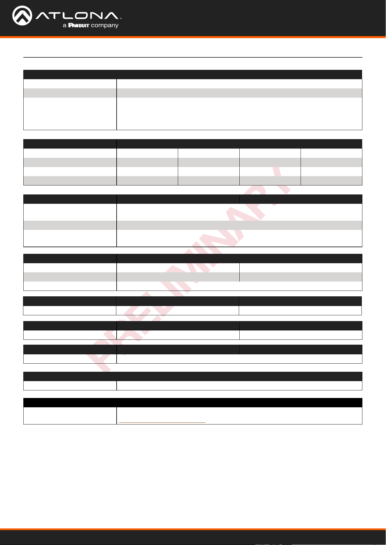
Appendix
Resolution / Distance 4K/UHD - Feet / Meters 1080p - Feet / Meters
USB-C 6.6 2 6.6 2
HDMI IN/OUT 15 5 30 10
CAT5e 295 90 330 100
CAT6/6a/7 330 100 330 100
Indicators, Buttons, and Controls
PWR indicator 1 - LED, green
LINK indicator 1 - LED, yellow
Buttons
DISPLAY, INPUT, UP, DOWN,
ENTER
Reset
5 - momentary, tact-type
1 - recessed, momentary
Power
Consumption Idle: 5.2W
Max: 108W
Supply PoE via connected receiver or *optional* 24V 5A power supply
BTU/h Idle: 18
Max: 27.28
Temperature Fahrenheit Celsius
Operating +32 to +104 0 to +40
Storage -4 to +140 -20 to +60
Humidity (RH) 20% to 90%, non-condensing
Dimensions (H x W x D) Inches Millimeters
Unit 0.98 x 5.91 x 9.84 25 x 150.2 x 250
Weight Pounds Kilograms
Device 1.65 0.75
Certication
Device CE, FCC
Compliance
NDAA-899 Yes
Warranty
Device To view the product warranty, use the following link:
https://atlona.com/warranty
(1) Scaler does not support frame rate conversion.
(2) HDR is supported on USB-C and HDMI ports only.
(3) Maximum limit of 6 USB hubs when traversing an HDBaseT link.
Footnotes

US International
atlona.com • 408.962.0515 • 41.43.508.4321
PRELIMINARY
35358-R1