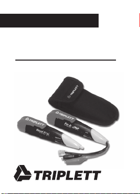
Fox Jr.
&
Hound Jr.
TRIPLETT
Instruction Manual

2
Table of Contents
1. Introduction . . . . . . . . . . . . . . . . . . . . . . 2
2. FOX Jr Features . . . . . . . . . . . . . . . . . . . 3
3. HOUND Jr Features . . . . . . . . . . . . . . . . 3
4. Fox Jr Diagram . . . . . . . . . . . . . . . . . . . 4
5. Hound Jr Diagram . . . . . . . . . . . . . . . . . 5
6. Safety Warnings and Cautions . . . . . . . . 6
7. Specifications . . . . . . . . . . . . . . . . . . . . 9
8. Getting Started . . . . . . . . . . . . . . . . . . . 12
9. Detailed Information . . . . . . . . . . . . . . . 16
10. Accessories and Replacement Parts . . 30
11. Fox Jr. & Hound Jr. in Carrying Case . . 31
12. Product Return Instructions . . . . . . . . 32
13. Warranty . . . . . . . . . . . . . . . . . . . . . . . 34
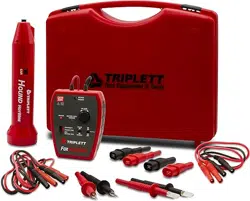
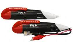
1. Introduction
The Triplett FOX Jr and HOUND Jr Wire Tracing
Kit consists of the FOX Jr Compact Toner, the
Hound Jr Compact Probe, and the convenient
belt pouch / carrying case. These compact ver-
sions of the popular Triplett FOX and HOUND
series of products offer less demanding users
a portable low cost wire tracing solution.
84-862 11/06

3
2. FOX Jr. Features
• Pocket-Sized with Pocket Clip
• Connects easily with alligator clips or
RJ-11 / RJ-45 combo plug
• Distinctive Warble tone is adjustable over
wide range
• 120VAC Line Cross Resistant
• Powered by one A23 Battery (included)
• 1 Year Warranty
3. HOUND Jr. Features
• Pocket-Sized with Pocket Clip
• Small and Streamlined to get into tight places
• Adjustable Sensitivity / Volume Control
• Visual Signal Strength Indicator
• Contains Hi-Gain Hi-Impedance Amplifier
• Non-Conductive Probe Tip
• Detects FOX Jr Signal from up to 12" away
• Earphone Jack
• Power Beeper Reminder
• Powered by one A23 Battery (included)
• 1 Year Warranty
4
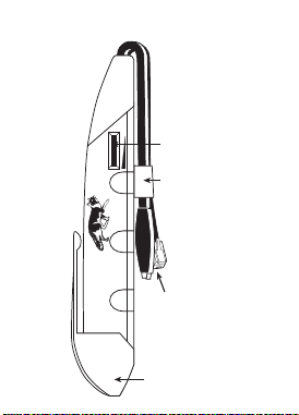
OFF
PITCH
Fox Jr.
Tone Generator
Battery Cover /
Pocket Clip
Alligator Clip Leads
& RJ-11/RJ-45 Combo
Plug Lead
On - Off /
Pitch Control
Lead Holder
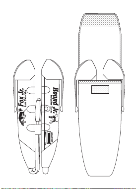
4. Fox Jr. Diagram
5
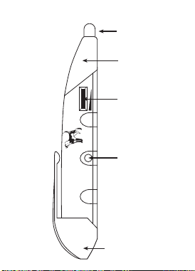
OFF
SENSITIVITY
Hound Jr.
Inductive Tracer
On - Off /
Sensitivity
Control
Battery Cover /
Pocket Clip
Earphone
Jack
Inductive
Probe Tip
Visual Signal
Strength
Indicator (LED)
5. Hound Jr. Diagram

6
6. Safety Warnings and Cautions
6.1
Do not connect FOX Jr or HOUND Jr to any
source of AC power. AC voltages above 30 volts
can be dangerous, and may result in user in-
jury. The FOX Jr and HOUND Jr are not in-
tended to trace live AC power lines. The FOX
Jr will be damaged if connected to a live AC
power line.
6.2
Use care when using the HOUND Jr to probe
any wire or cable. An unexpected dangerous
voltage may be present, which may result in
injury to the user.
6.3
Use caution when working with telephone lines.
They can support dangerous voltages. 50VDC
is often present, and 100VAC may be present
during ringing. Additionally, telephone lines may
support dangerous levels of common mode

7
voltages. In some circumstances, user injury
may result.
6.4
Use caution when working with any long un-
connected wire or cable. Under some condi-
tions, unconnected wires may “float up” to
dangerous potentials, and touching them may
result in user injury.
6.5
Use care when connecting the FOX Jr to any
wire or cable. An unexpected dangerous volt-
age may be present, which may result in injury
to the user.
6.6
Potentials applied to any connection of the FOX
Jr may appear on other FOX Jr connections. For
example, a potential applied to the RJ-11 plug
may appear on the alligator clips. This could
pose a shock hazard to the user, if for example,
a telephone cable with 120VAC on it is con-

8
nected to the FOX Jr. The 120VAC may appear
on the alligator clips, and shock the user.
6.7
Do not use the FOX Jr or HOUND Jr if either
unit appears to be damaged. A damaged unit
may lead the user to a false conclusion, result-
ing in user injury.
6.8
Do not use the FOX Jr or HOUND Jr if either
unit is wet. A wet unit may result in shock or
injury to the user if connected to live circuitry.
***WARNING***
The FOX Jr and HOUND Jr are designed
to work on non-energized (except
telephone lines) wires or cables.
Attempting to test energized wires may
damage the FOX Jr and HOUND Jr,
cause user injury, or both.

9
7. Specifications
7.1 FOX Jr. Specs
Output Voltage: 6 volts peak to peak square
wave into an open circuit
Output Type: Warble
Output Frequency Range: 800Hz to 5KHz
Frequency Adjustment: Thumbwheel
Overload Protection: Tolerates 120 volts AC at
60Hz at alligator clips or
modular plug
Connections: Alligator clips and RJ-11 /
RJ-45 Combo modular plug
Lead Length: Approx 4"
Battery: A23, 12 volt , Triplett 37-60
(protected against the
accidental reversal of the
battery polarity)
Size: 5.8" (L) x 1.25" (W) x 0.8" (H)
Weight: Approx 1.6 oz.

10
7.2 HOUND Jr. Specs
Amplifier: JFET and Integrated Circuit for
Hi-Impedance and Hi-Gain
Sensitivity: Adjustable with thumbwheel,
detects FOX Jr up to 12" away
Probe: Non-conductive, insulated
probe
Earphone Jack: Accepts standard 1/8"
(3.5mm) mini phone plug,
either mono or stereo.
For use with electromagnetic
(dynamic) earphones from
8 Ohms to 2000 Ohms.
Automatically mutes loud-
speaker when earphone is
used. An earphone with a
shielded cable is suggested to
reduce the possibility of feed-
back from the cable to the
probe tip.
Signal Strength Indicator: Bright red dual LED
visual signal strength indicator

11
Battery: A23, 12 volt , Triplett 37-60
(protected against the
accidental reversal of the
battery polarity)
Power Beeper Reminder: HOUND Jr beeps and
flashes periodically to remind
user that it is on.
Size: 5.8" (L) x 1.25" (W) x 0.8" (H)
Weight: Approx 1.7 oz.
7.3 FOX Jr. & HOUND Jr. Kit
Case Size: 6.2" (L) x 2.8" (W) x 1.3" (H)
Weight: Approx 4 oz.
(both units & case)

12
8: Getting Started
8.1 Installing Batteries
Remove the black pocket clip from both the FOX
Jr and HOUND Jr. Install an A23 battery in each
product, observing proper polarity (negative
towards tip), and replace the pocket clips.
8.2 Initial Tests
Turn on the HOUND Jr by rotating its
thumbwheel from the off position to the fully
on position. At this time, you may not hear any
sound from the HOUND Jr, or you might hear a
buzzing sound if fluorescent lights or other elec-
tronic equipment are operating in the vicinity. If
you leave the HOUND Jr operating this way, it
will beep and flash periodically to remind you
it is turned on.
With the HOUND Jr’s tip positioned near the
leads of the FOX Jr, turn on the FOX Jr by rotat-
ing its thumbwheel from the off to on position.

13
The FOX Jr’s warbling signal should be heard
coming from the HOUND Jr. Adjust the
thumbwheel on the FOX Jr while listening to the
HOUND Jr. Notice how some pitches of the
sound are louder than others. In use, the user
will usually adjust the FOX Jr to one of the louder
pitches, so the HOUND Jr will be easier to hear
while tracing wires.
With the FOX Jr adjusted to one of the louder
pitches, experimentally position the tip of the
HOUND Jr in different locations around the leads
of the FOX Jr, noting how the loudness of the
HOUND Jr, and the brightness of the signal
strength LEDs, increase as the leads are ap-
proached. Adjust the thumbwheel on the
HOUND Jr to reduce its loudness when the
HOUND’s tip is right against one of the FOX’s
leads.
The HOUND Jr’s earphone jack accepts a stan-
dard 1/8" (3.5mm) mini-plug. This type is often
used with portable music playing devices. The

14
earphone may be either a stereo or mono type.
For best results, the lead wire should be shielded
to reduce the possibility of feedback occurring
between the lead wire and the HOUND Jr’s
probe. When the plug is inserted into the jack,
the HOUND Jr’s speaker is turned off, and the
sound can only be heard through the earphone.
To use the earphone, turn on the HOUND Jr with
the Volume / Sensitivity thumbwheel to mini-
mum, and then plug the earphone into jack.
Adjust the thumbwheel for a comfortable sound
level in the earphone.
Helpful Hints
Setting the Volume / Sensitivity thumbwheel to
minimum prior to using the earphone, as previ-
ously described, can often save the user from a
jarring experience. Sounds that are not very loud
in the speaker, can be very loud in the earphone.
When using the earphone, the high gain of the
HOUND Jr’s circuitry may cause “feedback” at
high thumbwheel settings. Feedback is a squeal-

15
ing or whining sound, and it can be very loud,
so use caution. Reduce the thumbwheel setting
to reduce the feedback.
Because the FOX Jr’s test leads are so short,
the HOUND Jr may not detect the warble signal
more than a few inches away. When the FOX Jr
is connected to longer wires, the HOUND Jr’s
sensing distance will improve.
At high thumbwheel settings, the HOUND Jr’s
high sensitivity may cause the Signal Strength
LED to flash when the tip is tapped or rubbed.
This is normal.

16
9: Detailed Information
9.1 Methods
Two different basic tracing methods are com-
monly used . . . the “LINE/GROUND” connec-
tion, and the “LINE/LINE” connection.
9.1.1 LINE/GROUND Connection
The LINE/GROUND connection produces the
strongest tracing signal, but also creates
“crosstalk” of the signal into other wires in the
cable. If the user is trying to identify a cable,
and not an individual conductor in the cable,
the LINE/GROUND method usually produces the
best results. This method has been used to trace
electrical wires (like Romex), speaker wires,
intercom wires, thermostat wires, alarm wires,
cable television wires, etc. through drywall,
wood flooring, and carpeting.
A “good” earth ground is usually not required.
In fact, a large metal object like an office desk,
a file cabinet, or a metal plate on the floor, can

17
be used. On vehicles, the metal chassis of the
vehicle can be used as the ground. A metal
hulled boat can use the hull as a ground, and a
wood or fiberglass hulled boat an use the sur-
rounding water as a ground (make connection
to a metal fitting in contact with the water or
drop a wire into the water). The ground con-
nection is only required at the FOX Jr end of the
cable or wire, however, a ground connection at
the far end is handy for identification of the tar-
get wire (read following text on tracing).
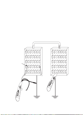
To setup the LINE/GROUND connection, clip one
alligator clip (either color) of the Triplett FOX
Jr to the “ground”, and the other alligator clip
to the wire being traced. (See Figure 1)
9.1.2 LINE/LINE Connection
The LINE/LINE connection is useful for identi-
fying a pair of wires in a multi-wire cable, or for
identifying a pair of wires in a bundle of wires.
When wires are “paired” in a cable, they are of-
ten twisted together in a manner that reduces
18
crosstalk of any signal on the wires into adja-
cent wire pairs. Telephone cables are con-
structed in this manner, so a LINE/LINE con-
nection is often used to trace telephone cables.
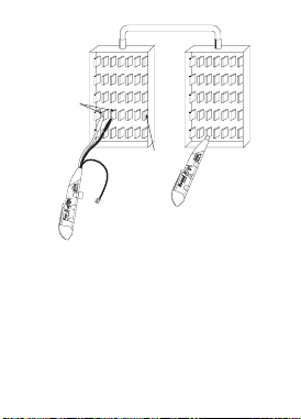
The FOX Jr’s modular plug applies a LINE/LINE
connection when plugged into its mating modu-
lar jack (connected to a telephone line).
(See Figure 2)
MULTI-WIRE CABLE
TERMINALS
TARGET
WIRE
Figure 1 Line/Ground Connection
19
MULTI-WIRE CABLE
TERMINALS
TARGET
WIRES
Figure 2 Line/Line Connection
9.1.3 Testing
Whether the LINE/GROUND or LINE/LINE con-
nection is used at the FOX Jr, the use of the
HOUND Jr for tracing the signal is the same. In
general, the HOUND Jr is used by bringing it
into proximity with the wire/cable that is being
traced, listening for the TONE signal from the

20
FOX Jr, and moving the HOUND Jr in such a
manner as to increase the loudness of the TONE
signal from the HOUND Jr’s speaker . . . i.e.
searching for the loudest TONE signal. The
HOUND Jr’s Volume Control is adjusted to a
comfortable level. Usually, it is set to maximum
when the tracing wires through walls and ceil-
ings, and is set to a lower setting when in close
proximity to the signal carrying wires. The
HOUND Jr’s LED glows brighter when the sound
from the speaker is louder. In situations where
there is a lot of acoustic noise, observing the
brightness of the LED, or using earphones, may
prove more useful than attempting to hear the
signal from the speaker.
To begin using the HOUND Jr, turn on the
HOUND Jr by rotating its thumbwheel from the
off position to the fully on position. It is normal
to hear a humming or buzzing noise coming
from the HOUND Jr’s speaker when it is in an
area with fluorescent lights, neon signs, trans-
formers, etc. In fact, an easy test to verify the

21
HOUND Jr is working is to move it toward an
operating fluorescent light and note that the
buzzing sound gets louder, and the brightness
of the LED increases. When used out-of-doors,
away from power wires, the HOUND Jr may
make only a slight hissing noise.
Before attempting to trace a wire/cable, with the
HOUND Jr’s tip positioned near the leads of the
FOX Jr, turn on the FOX Jr by rotating its
thumbwheel from the off to on position. The FOX
Jr’s warbling signal should be heard coming
from the HOUND Jr. Adjust the thumbwheel on
the FOX Jr to peak the loudness of the signal
received on the HOUND Jr.
Connect the FOX Jr to the target wire/cable in
the desired fashion. Once again, test the FOX
Jr’s output signal by bringing the HOUND Jr’s
tip near the FOX Jr’s alligator clips (this is called
“probing” the wire/cable). The warble TONE
should be heard from the HOUND Jr’s speaker.
If the warble TONE is not heard, the wire/cable

22
may be shorted. The HOUND Jr cannot trace a
shorted wire.
If the LINE/GROUND connection is being used,
the alligator clip connected to the ground should
have very little signal on it when probed by the
HOUND Jr. The other clip attached to the wire/
cable should have a strong signal on it.
If the LINE/LINE connection is being used, both
alligator clips should have about the same sig-
nal on them . . . although it will be noted that
neither of the signals are as strong as the sig-
nal produced by the LINE/GROUND connection.
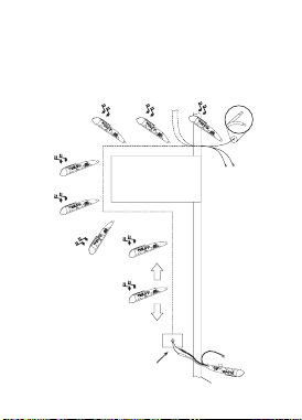
9.1.4 Tracing Wires in Walls, etc.
After connected the FOX Jr to one end of the
wire/cable, bring the HOUND Jr near the sus-
pect wire/cable. The FOX Jr signal can often be
heard a foot or more away from the wire. If
searching for wires in walls, move the HOUND
Jr along the surface of the wall, noting the lo-
cation of the strongest warble TONE pickup.
23
Using the HOUND Jr, trace the wire through the
wall by following the strongest warble TONE
pickup. (See Figure 3)
FLOOR
SPEAKER
WIRES
DOORWAY
ADDITIONAL
SPEAKER
WIRES
SEVERAL
SPEAKER
WIRES
MOMEMTARILLY
SHORT ENDS TO
“KILL” TRACER TONE
Figure 3

24
If the end of the wire/cable is exposed, for ex-
ample, in a junction or wall box, use the HOUND
Jr to determine if the FOX Jr warble TONE is
present. If so, you may have found the cable
you are looking for. You may find that several
cables in different junction boxes produce simi-
lar strength warble TONEs. This phenomenon
is caused by crosstalk . . . or “bleeding” of the
TONE signal into other wires or cables in prox-
imity to the target wire. Sometimes, the junc-
tion box contains several different wires/cables,
which due to size constraints of the box itself,
cannot be separated apart far enough to iden-
tify the wire/cable with the TONE signal on it.
To assist in identifying the target wire, use the
“Remote Tone Kill” technique.
The FOX Jr supports the use of the Remote Tone
Kill test method. When the wire or wires (pair)
that the FOX is connected to, are shorted out,
locally or remotely, the warble TONE signal from
the FOX Jr is “killed”.

25
In situations where it is difficult to identify the
target wire, because of crosstalk from other
wires, the target wire can be identified by short-
ing the TONE to ground (if the LINE/GROUND
connection is being used) or shorting out the
wire pair with the TONE on it (if the LINE/LINE
connection is being used). (See Figure 3) If you
have found the correct wire(s), the TONE will
be completely killed. If the TONE is still heard,
but reduced somewhat in level, you have not
found the target wire(s). This method is not fool-
proof, and experimentation, common sense, and
experience must be used to apply it properly.
However, in many instances, it will provide trace
verification. A caution . . . if you are at a loca-
tion where the only wire is not the target wire,
but it has a signal on it due to crosstalk . . . it
may appear that you have killed the FOX Jr
warble TONE when you short out the wire. To
make sure, leave the short on the wire in ques-
tion, and go back to FOX Jr, and test the alliga-
tor clips with the HOUND Jr. If the TONE is still
there, you have not shorted the target wire.

26
Note: Even with the FOX Jr’s alligator clips
shorted out, the case of the FOX Jr will still ra-
diate some warble TONE. Do not confuse this
with the warble TONE coming from the alligator
clips. Perform a few experiments by shorting
out the clips and probing the FOX Jr with the
HOUND Jr so you know what to expect.
9.1.5 Tracing Wires within a Cable
When searching for specific wires within a
bundle or cable, it is necessary to separate the
individual wires apart from each other at the end
of the cable opposite the FOX Jr location. Probe
the wires with the HOUND Jr, attempting to iden-
tify the wire with the strongest TONE on it. Ad-
just the HOUND Jr’s thumbwheel as necessary.
It is not necessary to pierce the insulation of
the wire. The wire with the strongest warble
TONE is the target wire. In some cases, crosstalk
into the other wires will make it difficult to de-
termine which wire has the strongest TONE on
it. Use the Remote Tone Kill method, previously
described, to identify the target wire.
27
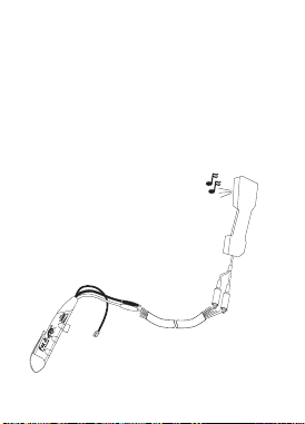
If tracing a pair of wires, such as those used for
a telephone line, a lineman’s talkset (also called
a “handset”, “buttset”, or “craftset”) can be used
to positively identify the pair. Connect the sus-
pect pair to the talkset. If you have located the
target pair, the FOX Jr warble TONE will be heard,
strong and clear, in the earpiece of the talkset.
(See Figure 4)
TALK SET
MULTI-CONDUCTOR
CABLE
Figure 4 Wire Tracing with a Talkset

28
HINTS:
The HOUND Jr works by capacitively sensing
the electrostatic field radiated by wires carry-
ing a signal (tone). The greater the radiated
field, the better the HOUND Jr’s ability to locate
a wire. Anything that reduces the intensity of
the field will impair the HOUND JR’s effective-
ness in locating a wire.
In general, several things affect field intensity .
. . shielding, signal (tone) amplitude on the wire,
and wire dress. In instances where a system is
shielded (shielded wires, metal junction boxes,
metal conduit, etc.), the effectiveness of the
HOUND Jr is impaired. In multi-wire cables,
grounded wires, or wires connected to low im-
pedance circuits, adjacent to the target wire can
act as shields, reducing the HOUND Jr’s ability
to sense properly. Spreading the wires apart
will reduce the shielding effect and allow the
HOUND Jr to work better. Defects in a cable or
wires, such as shorts or opens, will reduce the
signal amplitude and hence the HOUND Jr’s

29
ability to locate the target wire. Terminating a
wire or line in a low impedance also reduces
signal amplitude and the HOUND Jr’s locating
ability. It is also possible for wire dress to cause
nullification of the field. This may happen with
tightly twisted pairs of wires.
If the target wire is connected to other wires
and circuits, for example, to switches, lights,
relays, transformers, etc., the FOX Jr warble
TONE will pass through these devices and out
onto other wires connected to these devices ...
making tracing of the target wire very difficult,
if not impossible.
The FOX Jr and HOUND Jr cannot be used to
trace wires buried underground or in concrete.
This is because the moisture content of the earth
or of concrete allows the surface to be electri-
cally conductive, causing it to act as a shield
around the buried wire.

30
The HOUND Jr will not trace wires through a
metal conduit. It can, however, identify the wires
after they exit from the conduit.
General Rules for Effective Tracing:
1) Do what works best. Try both LINE/GROUND
and LINE/LINE tracing.
2) Separate wires when possible.
3) Move wires away from shielding when
possible.
4) Un-terminate wire if necessary.
5) Turn off noise sources to reduce buzzing
10: FOX Jr. and HOUND Jr.
Accessories and Replacement Parts:
Replacement FOX Jr. 3373
Replacement HOUND Jr. 3374
Carrying Case 10-4290
Earphone 13837
Battery (A23) 37-60
31
11: Fox Jr. & Hound Jr.
Shown In Carrying Case
Notice that Pocket Clips are
on the outside of the case.

32
12: TRIPLETT PRODUCT
RETURN INSTRUCTIONS
In the unlikely event that you must return
your Triplett equipment for repair, the
following steps must be taken.
1) Call 1-800-TRIPLETT to obtain a Return
Material Authorization (RMA) number
from Customer Service.
2) Enclose a copy of the original sales
receipt showing date of purchase.
3) Clearly print the RMA number on the
outside of the shipping container.
4) Return to: Triplett Corporation
One Triplett Drive
Bluffton, OH 45817
ATTN: Repair Dept.

33
Be sure to include a full description of the problem,
and a telephone number, street address, or email
address, where you can be contacted, and a return
address where the product can be shipped to upon
repair.

34
13: Warranty
ONE YEAR LIMITED WARRANTY
The Triplett Corporation warrants instruments and test equipment
manufactured by it to be free from defective material or workmanship
and agrees to repair or replace such products which, under normal
use and service, disclose the defect to be the fault of our manufactur-
ing, with no charge within one year of the date of original purchase
for parts and labor. If we are unable to repair or replace the product,
we will make a refund of the purchase price. Consult the Instruction
Manual for instructions regarding the proper use and servicing of in-
struments and test equipment. Our obligation under this warranty is
limited to repairing, replacing, or making refund on any instrument or
test equipment which proves to be defective within one year from the
date of original purchase.
This warranty does not apply to any of our products which have been
repaired or altered by unauthorized persons in any way so as, in our
sole judgment, to injure their stability or reliability, or which have been
subject to misuse, abuse, misapplication, negligence, accident or which
have had the serial numbers altered, defaced, or removed. Accesso-
ries, including batteries and fuses, not of our manufacture used with
this product are not covered by this warranty.
To register a claim under the provisions of this warranty, return the
instrument or test equipment to Triplett Corporation, Service Depart-
ment, One Triplett Drive, Bluffton, Ohio 45817, transportation pre-
paid. Upon our inspection of the product, we will advise you as to the
disposition of your claim.

35
ALL WARRANTIES IMPLIED BY LAW ARE HEREBY LIMITED TO A
PERIOD OF ONE YEAR FROM DATE OF PURCHASE, AND THE PROVI-
SIONS OF THE WARRANTY ARE EXPRESSLY IN LIEU OF ANY OTHER
WARRANTIES EXPRESSED OR IMPLIED.
The purchaser agrees to assume all liability for any damages and bodily
injury which may result from the use or misuse of the product by the
purchaser, his employees, or others, and the remedies provided for in
this warranty are expressly in lieu of any other liability Triplett Corpo-
ration may have, including incidental or consequential damages.
Some states (USA ONLY) do not allow the exclusion or limitation of
incidental or consequential damages, so the above limitation or ex-
clusion may not apply to you. No representative of Triplett Corpora-
tion or any other person is authorized to extend the liability of Triplett
Corporation in connection with the sale of its products beyond the
terms hereof.
Triplett Corporation reserves the right to discontinue models at any
time, or change specifications, price or design, without notice and
without incurring any obligation.
This warranty gives you specific legal rights, and you may have other
rights which vary from state to state.
TRIPLETT CORPORATION
BLUFFTON, OHIO
1-800-874-7538
www.triplett.com

Triplett Corporation One Triplett Drive Bluffton, OH 45817
800-TRIPLETT FAX: 419-358-7956 www.triplett.com
© Triplett Corporation All Rights Reserved