MILWAUKEE TOOL
l
www.milwaukeetool.com
13135 W. LISBON RD., BROOKFIELD, WI 53005
Drwg. 3
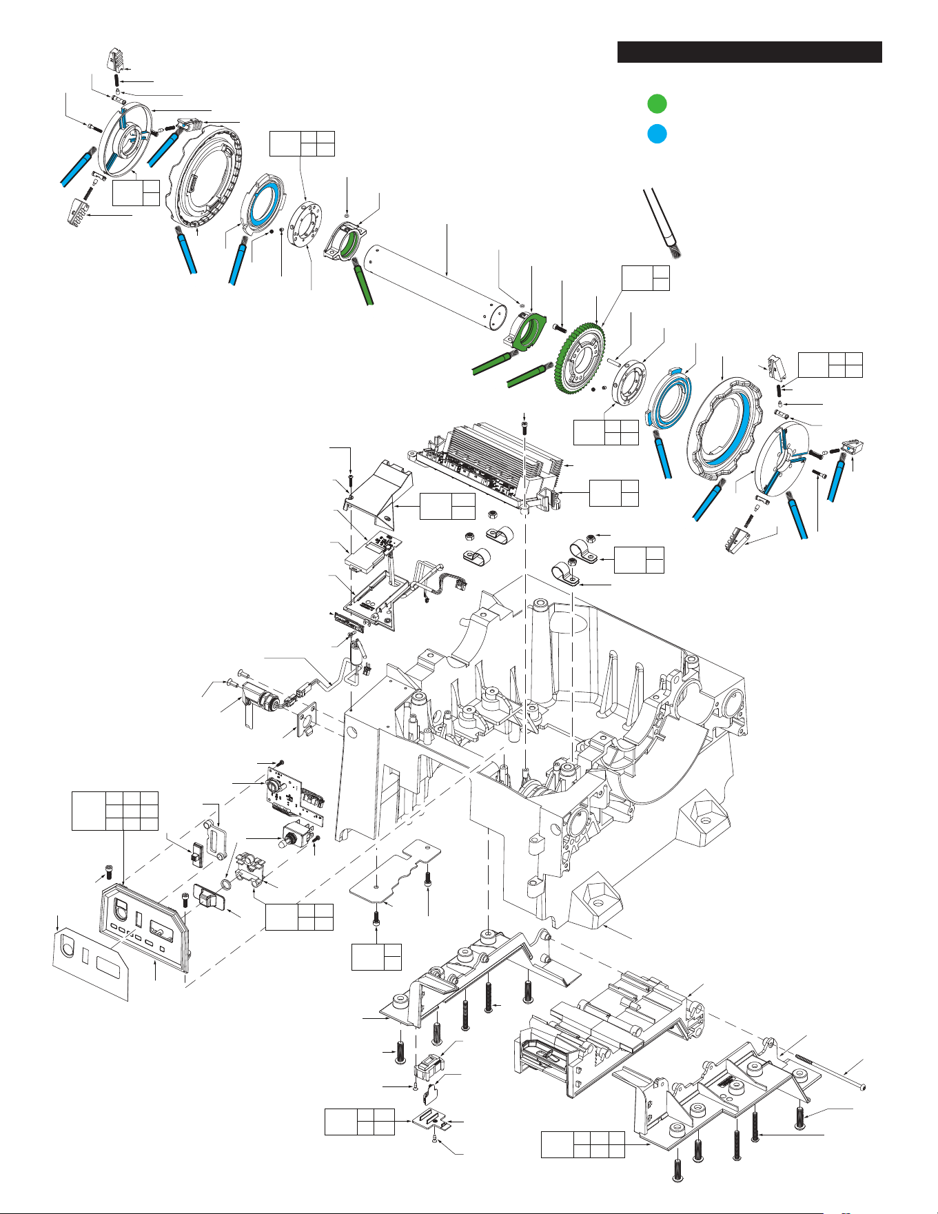
ACCESSORY CARRIAGE ASSEMBLY PAGE 6
POWER DRIVE ASSEMBLY PAGES 2-5
SCREW TORQUE CHARTS PAGE 5
CART ASSEMBLY PAGE 8
OIL RESERVOIR/SHROUD ASSEMBLY PAGE 7
WIRE ROUTING PAGE 9
BULLETIN NO.
54-27-F512
SERVICE PARTS LIST
CATALOG NO. MXF512
REVISED BULLETIN
SPECIFY CATALOG NO. AND SERIAL NO. WHEN ORDERING PARTS
MX FUEL™ PIPE THREADING MACHINE
SERIAL NO.
DATE
May 2025
WIRING INSTRUCTION
N31A
See Page 9
This product is to be serviced ONLY by personnel authorized by MILWAUKEE TOOL. Do NOT
attempt to purchase parts and install them yourself. Installation by anyone other than an authorized
MILWAUKEE personnel could void your warranty.
For service, parts, or inquiries, contact us:
• Customer Service at 1.800.SAWDUST (1.800.729.3878)
• E-Service tool repair at: www.milwaukeetool.com/e-service
• Find a local authorized MILWAUKEE service location at Milwaukeetool.com
• Find a MILWAUKEE factory Service Center Location or MILWAUKEE factory Central Repair
Center at Milwaukeetool.com. Send the following, prepaid and insured:
• Your name, address, and phone number
• Description of the issues
• Copy of the proof of purchase
• Tool, charger, and batteries involved with the issues
MILWAUKEE factory Central Repair Centers:
MILWAUKEE TOOL MILWAUKEE TOOL
Central Repair Central Repair
1401 Sycamore Avenue 2198 Southtech Drive
Greenwood, MS 38930 Greenwood, IN 46143
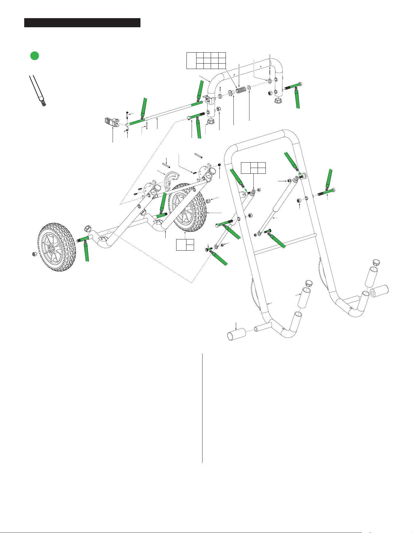
NOTE
Regarding parts to be lubricated:
Apply a light coating of grease to
all highlighted parts shown prior
to installation. Reference the key
above for grease types.
= Type “J” grease,
1-lb., 49-08-4220
122
40
47
66
110
96
(4x)
(4x)
(3x)
31
(4x)
29
76
(2x)
94
(4x)
93
(2x)
86
(2x)
(2x)
(2x)
(2x)
(2x)
(2x)
92
38
39
(8x)
19
35
14
16
38
22
15
17
20
43
44
74
95
23
108
1
21
18
(3x)
34
(4x)
75
45
46
3
(2x)
9
(2x)
118
2 40
66
119
38 74
95
9 38
46 75
120
43 44
108
121
3
39
125
34
37
124
9 38 45
75 86 92
93 94
2
109
37
(16x)
Electronics
Assembly
(see pg.4)
Chuck
Assembly
(see pg.4)
Foot Pedal
Assembly
(see pg.3)
123
14 15 16 17
18 19 20 21
22 23 35
42
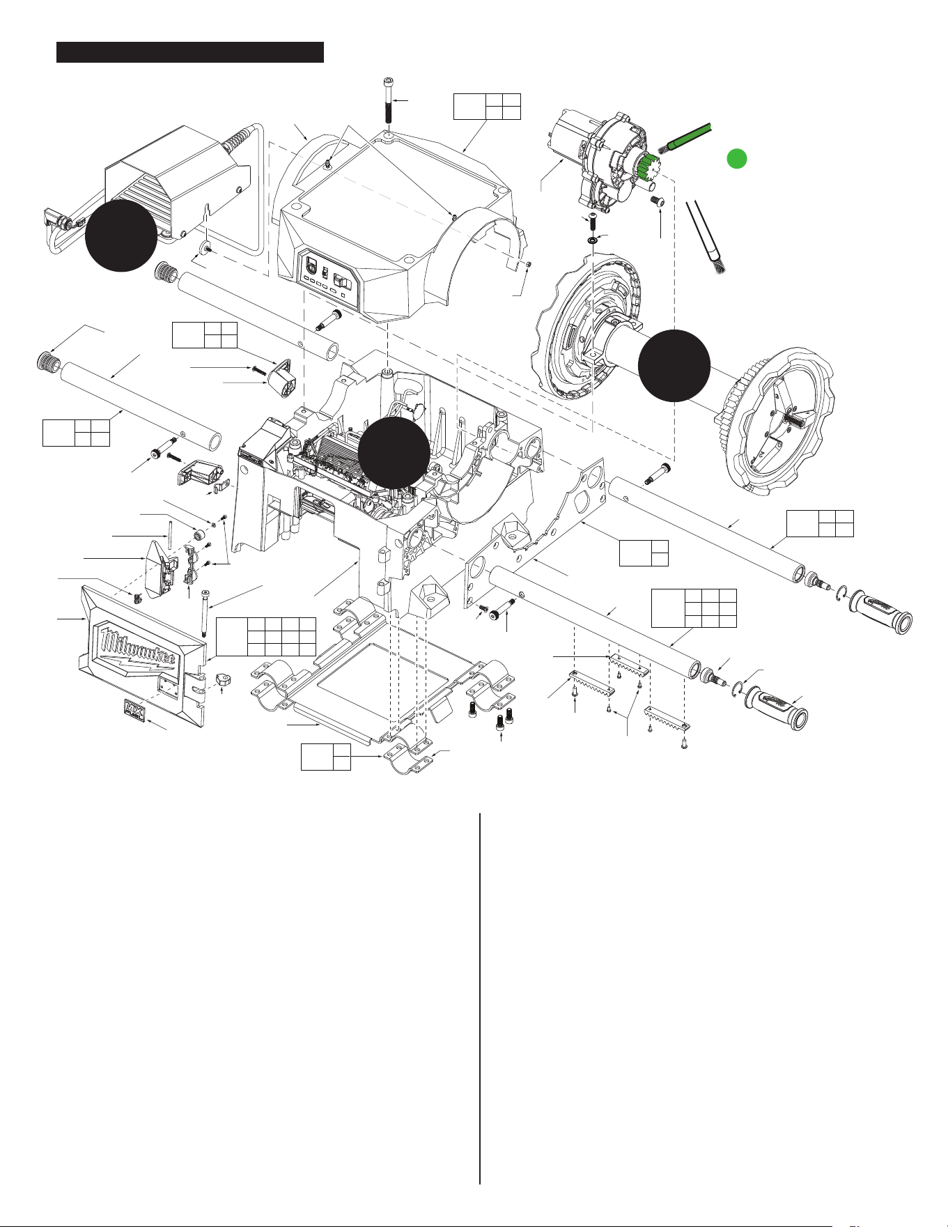
FIG. PART NO. DESCRIPTION OF PART NO. REQ.
1 44-66-7080 Base Housing (1)
2 --------------- Top Housing (1)
3 --------------- Front Frame (1)
9 34-60-7120 Retaining Ring (2)
14 --------------- Battery Door (1)
15 --------------- Paddle Door Latch (1)
16 --------------- Spring and Pin Cover (1)
17 --------------- Latch Pin (1)
18 05-83-0060 Battery Door Bolt (1)
19 --------------- MX Badge (1)
20 --------------- Battery Door Bumper (1)
21 05-86-0689 M3.5x8 screw (3)
22 --------------- Latch Spring (1)
23 45-88-8987 Bumper Washer (1)
31 44-20-0067 M8x30 BH screw (4)
34 --------------- Cart Mounts (4)
35 44-20-7260 Battery Door Bumper (1)
37 06-82-9730 M8x20 Screw (16)
38 05-83-0050 M8x1.25 Shoulder Bolt (4)
39 05-86-0672 M6x14 FH Screw (8)
40 05-86-0680 M10x85 Top Housing Screw (4)
42 06-14-0230 Foot Pedal Mounting Bolt (1)
43 --------------- Cord Wrap Hook (2)
44 06-82-9643 M5x25 BH Screw (2)
45 --------------- Accessory Arm (Drive Side) (1)
46 --------------- Accessory Arm (1)
47 14-29-8810 Gearbox Assembly (1)
66 --------------- Drive Tube Grease Zerk (2)
74 --------------- Roll Grooving Arm (2)
75 --------------- Acc Arm Press Inserts (2)
76 31-44-0260 Lift Handle (2)
92 --------------- Rack Part 2 (1)
93 --------------- Rack Part 1 (2)
94 05-81-0166 M4x.7 PH T20 Screw (4)
95 31-12-9060 Roll Grooving Arm Cap (2)
96 05-86-0674 M10x18 BH Screw (3)
108 --------------- Strain Relief Hook (1)
109 44-66-7255 Mounting Plate (1)
110 45-88-0311 Washer (4)
113 05-55-0037 M5 Nylon Nut (1)
118 14-46-9468 Top Housing Service Kit (1)
119 14-46-9470 Roll Grooving Arm Service Kit (Set of 1) (2)
120 14-46-9476 Cord Wrap Service Kit (Set of 1) (2)
121 14-46-9478 Front Face Housing Service Kit (1)
122 14-46-9472 Accessory Arm Service Kit (1)
123 14-20-9145 Battery Door Service Assembly (1)
124 14-46-9474 Accessory Arm Drive Side Service Kit (1)
125 14-46-9480 Cart Mount Service Kit (Set of 1) (4)
FIG. PART NO. DESCRIPTION OF PART NO. REQ.
MXF Power Drive Assembly
MXF Power Drive Assembly
85 86
90
113
56 57 73
78 79 80
81 83 86
114
29 77 84
87 88 89
111
117
84(4x)
77
89(2x)
73
88
80
85
86
(4x)
79
29
81
78
83
90(4x)
86(4x)
111
112
90
86
87
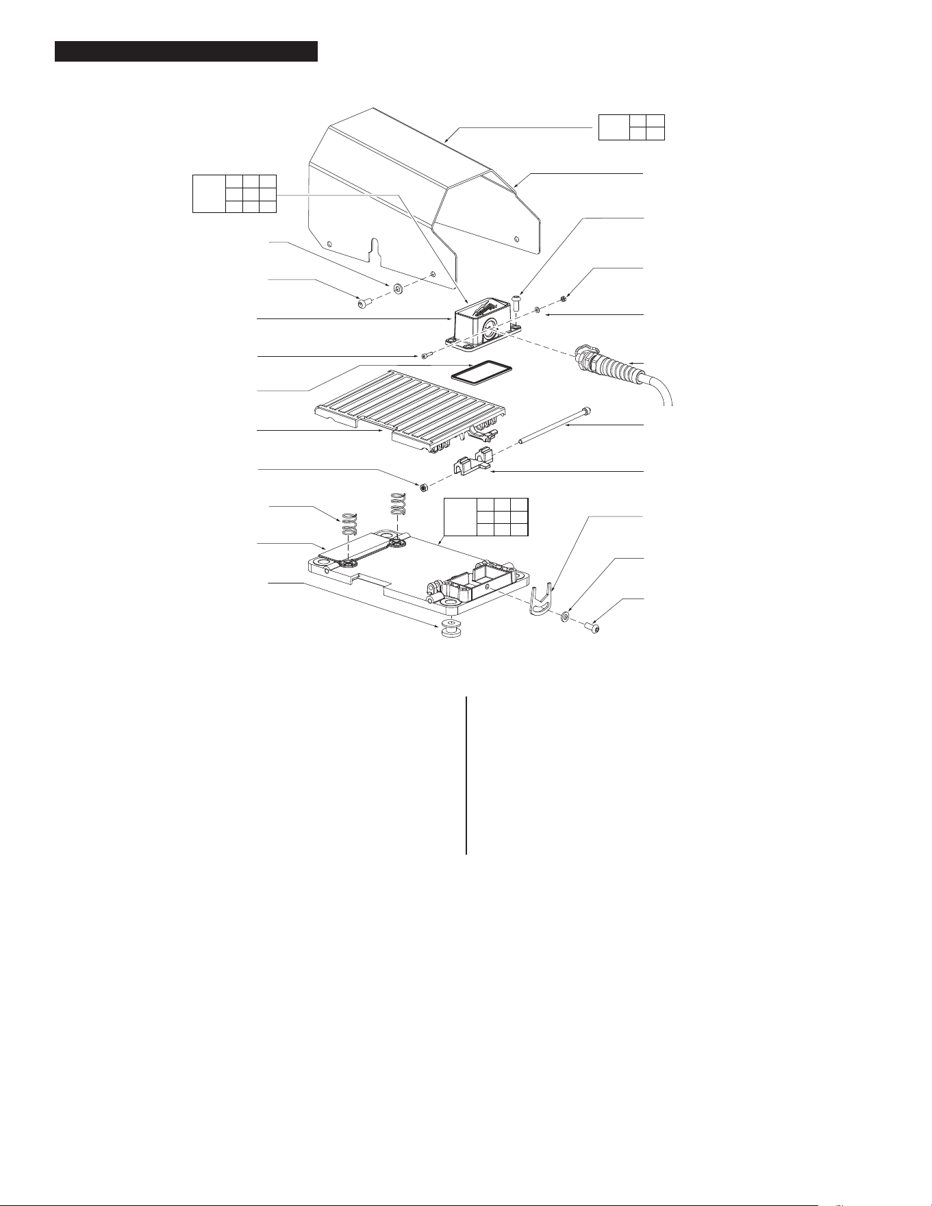
FIG. PART NO. DESCRIPTION OF PART NO. REQ.
29 05-55-0160 M5 Nut (1)
73 --------------- Foot Pedal Wiring Assembly (1)
77 --------------- Foot Pedal Base Plate (1)
78 65-34-3185 Foot Pedal Inner Seal (1)
79 06-55-3855 M3x.5 Hex Nut (1)
80 45-88-9005 Washer (1)
81 06-82-9647 M3x.5 Hex Screw (1)
83 --------------- Foot Pedal Cover (1)
84 --------------- Foot Pedal Bumper (4)
85 --------------- Foot Pedal Guard (1)
86 06-82-9725 M6x1 PH Screw (11)
87 --------------- Foot Pedal (1)
88 --------------- Foot Pedal Pin (1)
89 --------------- Foot Pedal Compression Spring (2)
90 45-88-8986 Washer (5)
111 --------------- Foot Pedal Stop Plate (1)
112 31-15-8975 Foot Pedal Locking Tab (1)
113 14-46-9482 Foot Pedal Guard Service Kit (1)
114 14-46-9484 Foot Pedal Cover Service Kit (1)
117 14-46-9466 Foot Pedal Base Plate Service Assy (1)
FIG. PART NO. DESCRIPTION OF PART NO. REQ.
Foot Pedal Assembly
Foot Pedal Assembly
MXF Power Drive Assembly
= Type “J” grease, 1-lb., 49-08-4220
= Dark Thread Cutting Oil,
1-gallon, 49-08-5100
NOTE
Regarding parts to be lubricated:
Apply a light coating of grease to
all highlighted parts shown prior
to installation. Reference the key
above for grease types.
62
58
68(3x)
69(3x)
54
59
48
36
65
52(3x)
50
51(3x)
55
(6x)
61
(6x)
60
53
64
(12x)
63
(12x)
49
36
65
49
53
55
58
68(3x)
69(3x)
54
59
61(3x)
60
62
Apply into
detent hole
(6x)
(6x)
49 51
63 64
128
61 68
69
130
49 63
64
127
50
52
126
54
62
129
72(4x)
91
(4x)
100
106
98
33(4x)
31(3x)
31
(3x)
32
(2x)
32
(2x)
101
28
25
24
1
26
30(5x)
27
97
99
33
102
57(2x)
56
10
(6x)
13
11
8
4
12
(2x)
10
(3x)
7
67
12(2x)
6
5
82
73
70(4x)
71(4x)
41
33
5 6
7
10
132
27 28
33
101
139
25 26 30
31 32
138
4 8 10
11 12 13
82
131
41
72
133
12
67
137
70
71
136
91
100
134
MXF Power Drive Assembly
Chuck & Electronics Assembly
FIG. PART NO. DESCRIPTION OF PART NO. REQ.
1 44-66-7080 Base Housing (1)
4 --------------- UI Plate (1)
5 --------------- Switch Slider (1)
6 --------------- Switch Mounting Plate (1)
7 23-66-8950 Toggle Switch (1)
8 --------------- Speed Selector (1)
10 14-20-0199 M3x10 Screw (9)
11 --------------- Speed Selector Retaining Plate (1)
12 05-86-0685 M5x15 Screw (4)
13 --------------- UI Board Assy. (1)
24 31-06-2215 Battery Rail (1)
25 --------------- Right Battery Housing (1)
26 --------------- Left Battery Housing (1)
27 --------------- Coin Cell Cover (1)
28 --------------- Coin Cell Pocket (1)
30 05-88-0087 M5x2.24 PH T20 Screw (5)
31 44-20-0067 M8x1.25 BH Screw (6)
32 06-81-0093 M6x1 BH Screw (4)
33 05-81-0233 M3x1.058 FH T10 screw (4)
36 34-40-8015 O-Ring (2)
41 --------------- PCB Assembly (1)
48 45-76-0860 Drive Tube (1)
49 --------------- Drive Hub (2)
50 --------------- Gear (1)
51 --------------- Drive Pin (3)
52 05-86-0688 M8x1 Screw (3)
53 44-66-7071 Front Scroll Plate (2)
54 44-66-7070 Front Jaw Plate (2)
55 45-94-0390 Hand Wheel (2)
56 --------------- Foot Pedal Mounting Bracket (1)
57 06-82-9710 M5x.8 FH Screw (2)
58 43-56-2575 Jaw #2 (2)
59 43-56-2570 Jaw #1 (2)
60 43-56-2580 Jaw #3 (2)
61 --------------- Jaw Insert (6)
62 05-86-0683 M6x1 Screw (12)
63 05-86-0673 Set Screw (12)
64 05-86-0677 Set Screw (12)
65 42-40-7047 Bushing (2)
67 --------------- Wire Routing Cover (1)
68 --------------- Jaw Insert Spring (6)
69 --------------- Jaw Insert Pin (6)
70 05-55-3005 M6X1 Lock Nut (4)
71 --------------- Wire Trap (4
72 05-86-0679 M4x.7 Screw (4)
73 --------------- Foot Pedal Wiring Assy (1)
82 --------------- UI Label (1)
91 06-82-9642 M3x.5 BH Screw (4)
97 42-92-3506 OKC Base Cover (1)
98 14-20-0291 OKC Card Service Kit (1)
99 44-66-7076 OKC Nameplate (1)
100 --------------- OKC Housing Cover (1)
101 --------------- PCB Assembly for Coin Cell (1)
102 23-66-8970 Trigger Extension Wire Assy. (1)
106 14-20-9115 OKC Host Board (1)
126 14-46-9494 Driven Gear Service Kit (1)
127 14-46-9492 Drive Hub Back Service Kit (1)
128 14-46-9490 Drive Hub Front Service Kit (1)
129 14-46-9496 Jaw Plate Service Kit (Set of 1) (2)
130 14-46-9498 Jaw Insert Service Kit (Set of 1) (6)
131 14-20-9150 UI Plate Service Assembly (1)
132 14-20-9155 UI Switch Service Assembly (1)
133 14-46-9500 PCB Kit (1)
134 14-46-9505 OKC Housing Cover Service Kit (1)
136 14-46-9510 Wire Trap Service Kit (Set of 1) (4)
137 14-46-9512 Wire Routing Cover Service Kit (1)
138 14-46-9514 Battery Housing Service Kit (1)
139 14-46-9516 Coin Cell Service Kit (1)
FIG. PART NO. DESCRIPTION OF PART NO. REQ.
SCREW TORQUE SPECIFICATIONS
SEAT TORQUE
FIG. PART NO. WHERE USED (kgf-cm) (lb-in)
7 23-66-8950 UI Switch Assy 8-10 7-9
10 14-20-0199 UI Switch Assy 6-8 5-7
12 05-86-0685 User Interface to Housing Base 13-17 11-15
12 05-86-0685 Foot Pedal Wire Routing Cover 23-35 20-30
18 05-83-0060 Battery Door Assembly 81-115 70-100
21 05-86-0689 Battery Door Assembly 6-8 5-7
27a 05-81-0233 Coin Cell Kit 6-8 5-7
30 05-88-0087 Battery Housing Kit 15-20 13-17
31 44-20-0067 Battery Housing Kit 92-115 80-100
31 44-20-0067 Chuck Assembly 179-213 155-185
32 06-81-0093 Battery Housing Kit 46-58 40-50
33 05-81-0233 Coin Cell Kit 6-8 5-7
37 06-82-9730 Cart Mount Kit 167-207 145-180
38 05-83-0050 Arm Kit 184-230 160-200
39 05-86-0672 Side Housing 71-98 62-85
40 05-86-0680 Top Housing 161-207 140-180
42 06-14-0230 Foot Pedal 21-25 18-22
44 06-82-9643 Cord Wrap Kit 46-69 40-60
52 05-86-0688 Chuck Gear 461-691 400-450
57 06-82-9710 Foot Pedal 6-8 5-7
62 05-86-0683 Chuck Jaw Plate 115-150 100-130
63 05-86-0673 Chuck Assembly 86-115 75-100
64 05-86-0677 Chuck Assembly 86-115 75-100
66 43-33-0055 Top Housing 35-40 30-35
70 05-55-3005 Wire Trap Kit 23-35 20-30
72 05-86-0679 PCB Assembly 9-13 8-11
73 22-64-5275 Foot Pedal 35-40 30-35
81 06-82-9647 Foot Pedal Cover 7-9 6-8
86 06-82-9725 Foot Pedal Guard 69-81 60-70
88 44-60-5295 Foot Pedal Cover 45-51 39-44
91 06-82-9642 OKC Housing Cover 6-8 5-7
94 05-86-0675 Arm Kit 23-29 20-25
96 05-86-0674 Gearbox 161-202 140-175
99a 05-81-0233 OKC Nameplate 6-8 5-7
SCREW TORQUE SPECIFICATIONS
SEAT TORQUE
FIG. PART NO. WHERE USED (kgf-cm) (lb-in)
5 05-86-0668 Die Head 124-153 108-133
18 44-60-7080 Auto Release Lever 23-29 20-25
23 06-82-9646 Die Scroll 41-50 36-43
27 05-86-0667 Die Adjustment 23-29 20-25
32 05-83-0040 Reamer Arm 46-58 40-50
57 08-90-4507 Carriage 138-173 120-150
58 06-82-9645 Carriage 60-71 52-62
SCREW TORQUE SPECIFICATIONS
SEAT TORQUE
FIG. PART NO. WHERE USED (kgf-cm) (lb-in)
3 06-14-0310 Pump Cover 29-37 25-32
10 08-90-4510 Oil Pump Housing 58-69 50-60
13 06-74-1095 Oil Pump Housing 29-37 25-32
14 08-90-4506 Oil Reservoir Cover 58-69 50-60
19 06-82-9644 Oil Reservoir 6-9 5-8
22 05-86-0671 Oil Reservoir Cover 15-20 13-17
SCREW TORQUE SPECIFICATIONS
SEAT TORQUE
FIG. PART NO. WHERE USED (kgf-cm) (lb-in)
3 --------------- Cart Handle 138-173 120-150
19 --------------- Gas Spring 230-265 200-230
20 --------------- Gas Spring 230-265 200-230
25 --------------- Cart Handle 46-69 40-60
26 --------------- Wheel Weldment 69-81 60-70
28 --------------- Wheels 184-242 160-210
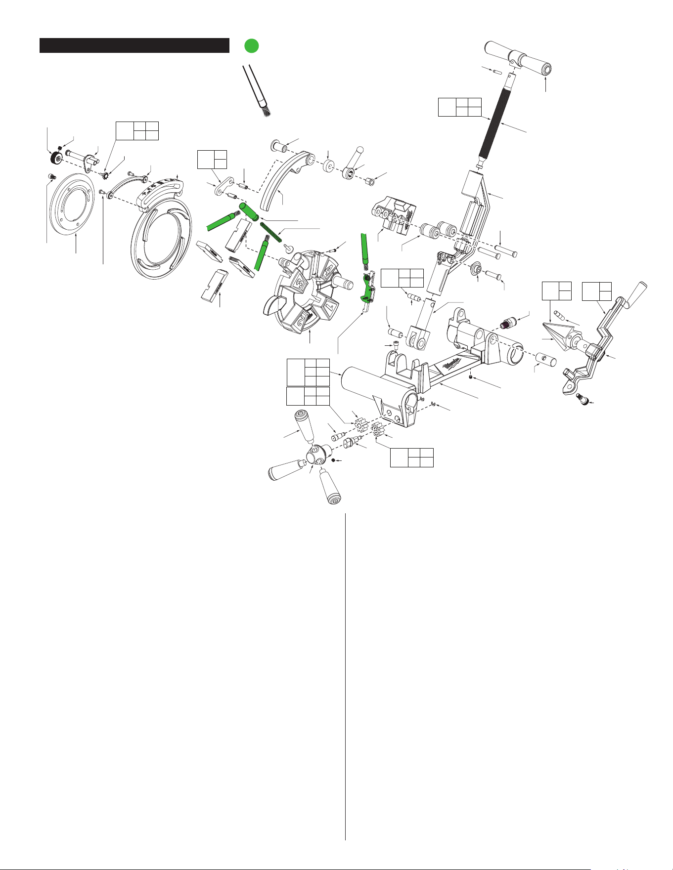
MXF Power Drive Assembly Accessory Carriage Assembly
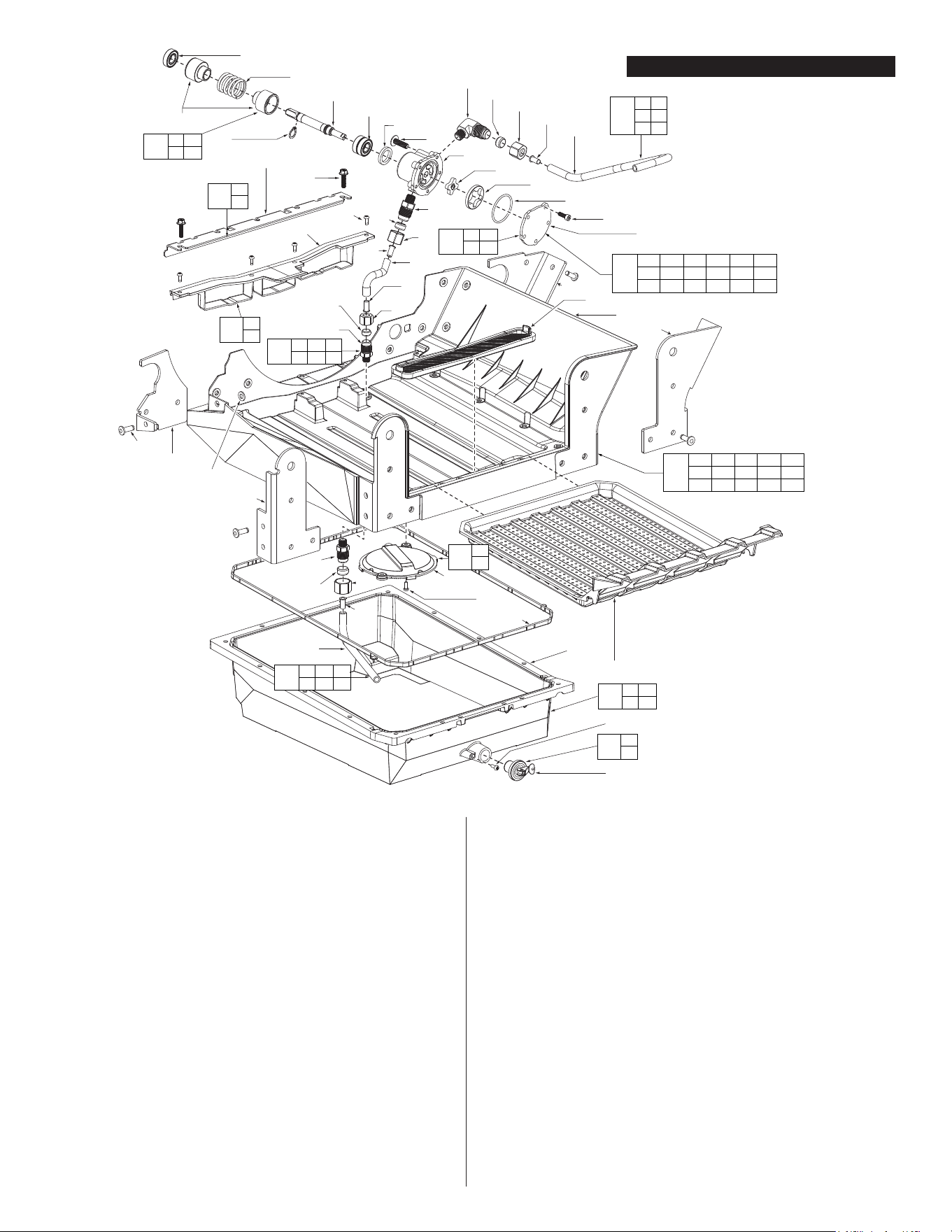
Oil Reservoir/Shroud Assembly
Cart Assembly
Chuck & Electronics Assembly
5
(4x)
4
23
(2x)
19
(2x)
66
72
49
40
73
61
75
47(2x)
27
22
70
21
24
2
6
71
14
25
69
18
8
12
43
41
42
36
76(2x)
35
32
33
31
50
58
51
59
(2x)
56
54
58
55
60
(3x)
52
53
77
57
34
11
10
51 57
58
59
61
74
52 53
59
82
54 56
59
83
41 42
43
78
35 40
49
81
21 22
27
79
6
19
80
31
34
84
33
34
85
NOTE
Regarding parts to be lubricated:
Apply a light coating of grease to
all highlighted parts shown prior
to installation. Reference the key
above for grease types.
45
= Type “J” grease, 1-lb., 49-08-4220
FIG. PART NO. DESCRIPTION OF PART NO. REQ.
2 44-66-7078 Die Scroll Plate (1)
4 44-66-7077 Die Head Oil Plate (1)
5 05-86-0668 M6x10 Screw (4)
6 --------------- Locking Arm Linkage (1)
8 42-40-0793 Die Locking Bushing (1)
10 42-40-7105 Bushing (1)
11 44-60-5283 Die Locking Pin (1)
12 44-40-7105 Flange Nut (1)
14 44-60-5281 Quick Release Pin (1)
18 44-60-7080 Auto Release Assembly Pin (1)
19 44-60-5395 M8x20 Coil Pin (2)
21 --------------- Die Adjustment External Gear (1)
22 --------------- Adjustment Knob (1)
23 06-82-9646 M5x10mm Screw (2)
24 32-60-7045 Die Adjustment Internal Gear (1)
25 40-50-3310 Auto Release Compression Spring (1)
27 --------------- M5x5mm Set Screw (1)
31 --------------- Reamer Arm (1)
32 05-83-0040 M81.25x13 Shoulder Bolt (1)
33 --------------- Reamer Cone (1)
34 --------------- Reamer Pin (1)
35 --------------- Cutter Arm (1)
36 43-40-0940 Cutter Frame (1)
40 --------------- Slider Pin (1)
41 --------------- Cutter Handle (1)
42 --------------- Cutter Threaded Rod (1)
43 44-60-5287 Cutter Handle Pin (1)
45 --------------- 15 Degree Cutter (1)
47 42-40-0795 Cutter Bushing (2)
49 --------------- Cutter Carriage Pin (1)
50 44-60-5505 Reamer Carriage Pin (1)
51 --------------- Carriage Base (1)
52 --------------- Idler Pin (1)
53 --------------- Rack System Idler Pinion (1)
54 --------------- Handle Hub Pin (1)
55 43-78-0645 Handle Hub (1)
56 --------------- Rack System Driver Pinion (1)
57 08-90-4507 3/8-to-1/4 Adapter (1)
58 06-82-9645 M6x6mm Set Screw (3)
59 44-90-5270 5x.6mm E-Ring (2)
60 43-98-7040 Carriage Handle (3)
61 05-86-1050 M8x1.25 Screw (1)
66 --------------- Universal 1-2" NPT Dies (1)
69 40-50-9275 Die Head Compression Spring (1)
70 14-02-0110 Die Lock Service Assembly (1)
71 14-02-0115 Die Lock Arm Service Assembly (1)
72 14-02-0120 Die Carrier Service Assembly (1)
73 14-02-0125 Auto Release Service Assembly (1)
74 14-02-0130 Carriage Service Kit (1)
75 14-02-0135 Sliding Cutter Service Assembly (1)
76 14-02-0140 Roller Cutter Service Assembly (1)
77 14-02-0145 Cutter Wheel Service Assembly (1)
78 14-02-0150 Cutter Handle Service Assembly (1)
79 14-46-9452 Die Adjustment Service Kit (1)
80 14-46-9454 Locking Arm Linkage Service Kit (1)
81 14-46-9456 Cutter Arm Service Kit (1)
82 14-46-9458 Idler Pin Service Kit (1)
83 14-46-9460 Driver Pinion Service Kit (1)
84 14-46-9462 Reamer Arm Service Kit (1)
85 14-46-9464 Reamer Cone Service Kit (1)
FIG. PART NO. DESCRIPTION OF PART NO. REQ.
Accessory Carriage Assembly
Accessory Carriage Assembly
16
8
16
38
13
10
24
28
2
7
6
5
4
3
14
39
39
24
40
40
24
34
31
23
33
35
36
(19x)
37
(19x)
32
14
40
18
19
20
1
21
19
17
24
39
27
26
39
40
14
9
11(2x)
22
(17x)
19
(4x)
29
12
15
10 24
28 39
40
50
14 24 26
39 40
49
14 24 27
39
40
46
17 19
21
47
9 11
15 16
42
3 4
5
43
12
22
51
19
29
52
17
19
48
18
19
45
44
12 14 19 23 29
32 33 34 35 36
37 39 40
41
2 3 4 5 6 7
8 9 10 11 13 14
15 16 38 39 40
FIG. PART NO. DESCRIPTION OF PART NO. REQ.
1 45-76-0047 Oil Reservoir Seal (1)
2 --------------- Oil Pump Housing (1)
3 06-14-0310 M4x12mm Bolt (5)
4 --------------- Pump Cover (1)
5 --------------- Oil Pump O-Ring (1)
6 --------------- Out Rotor (1)
7 --------------- In Rotor (1)
8 --------------- Spline Drive Shaft (1)
9 --------------- Pump Retaining Spring (1)
10 08-90-4510 3/8x1/8 Elbow Adapter (1)
11 --------------- Pump Bearing Cup (2)
12 42-92-7220 ReservoirCoverStiener (1)
13 06-74-1095 M6x20mm Bolt (1)
14 08-90-4506 3/8x1/8 Male Adapter (3)
15 --------------- Retaining Ring (1)
16 --------------- Ball Bearings (3)
17 --------------- 5/8" Plug (1)
18 --------------- Oil Filter House (1)
19 06-82-9644 M4x12mm Screw (7)
20 44-66-7095 Oil Filter Tray (1)
21 --------------- Oil Reservoir (1)
22 05-86-0671 M5x20mm Screw (17)
23 --------------- Oil Reservoir Cover (1)
24 --------------- 3/8 Adapter Seal (4)
26 --------------- Oil Reservoir Tube (1)
27 --------------- Filter Housing Tube (1)
28 --------------- Carriage Tube (1)
29 --------------- Oil Catch (1)
31 43-31-4020 Oil Filter (1)
32 --------------- Front Hanger Bracket (1)
33 --------------- Front Hanger Bracket (1)
34 --------------- Rear Hanger Bracket (1)
35 --------------- Rear Hanger Bracket (1)
36 06-72-1820 Oil System Rivet (19)
37 45-88-9030 Washer (19)
38 --------------- O-Ring (1)
39 05-55-3085 Compression Fitting Nut (4)
40 05-59-2050 Compression Fitting Sleeve (4)
41 14-02-0100 Pump Service Assembly (1)
42 14-46-9435 Pump Retaining Service Kit (1)
43 14-46-9437 Pump Seal Service Kit (1)
44 14-02-0105 Oil Reservoir Cover Service Assembly (1)
45 14-46-9440 Oil Filter House Service Kit (1)
46 14-46-9442 Tube Filter Housing Service Kit (1)
47 14-46-9444 Oil Reservoir & Plug Service Kit (1)
48 14-46-9446 Plug Expansion Service Kit (1)
49 14-46-9448 Oil Reservoir Tube Service Kit (1)
50 14-46-9450 Oil Carriage Tube Service Kit (1)
FIG. PART NO. DESCRIPTION OF PART NO. REQ.
Oil Reservoir/Shroud Assembly
Oil Reservoir/Shroud Assembly
NOTE
Regarding parts to be lubricated:
Apply a light coating of grease to
all highlighted parts shown prior
to installation. Reference the key
above for grease types.
= Type “J” grease,
1-lb., 49-08-4220
2 7 8 10
11 13 16 23
24 25
41
12 14
19
20
42
15
28
40
3
(2x)
26
(3x)
27
28
(2x)
15
(2x)
19(2x)
21
(2x)
12
(2x)
20
(2x)
3
(2x)
4
(2x)
18
(2x)
17
14
(2x)
29
(2x)
9
5
1
(8x)
21
10
11
Install
Hole D
D
C
B
A
Install
Hole B
Install
Hole A
Install
Hole C
8
25
24
13
16
7(2x)
23(2x)
2
6
FIG. PART NO. DESCRIPTION OF PART NO. REQ.
1 14-46-9720 Tube Cap (8)
2 --------------- Washer (1)
3 --------------- M10x1.5mm Shoulder Screw (4)
4 14-46-9725 Rubber Foot (2)
5 --------------- Wheel Weldment (1)
6 --------------- Locking Tube Weldment (1)
7 --------------- Bushing (2)
8 --------------- Lock Handle (1)
9 --------------- Back Lock Plate (1)
10 --------------- Lock Spring Stop (1)
11 --------------- Lock Spring (1)
12 --------------- Gas Spring (2)
13 --------------- Lock Handle Torsion Spring (1)
14 --------------- M8 Lock Nut (2)
15 --------------- Breaker Wheel (2)
16 --------------- Lock Shaft (1)
17 --------------- Cart Handle Assembly (1)
18 14-46-9730 Cart Handle Grip (2)
19 --------------- Bolt (2)
20 --------------- M8x1.25 Lock Nut (2)
21 --------------- M12x1.25 Lock Nut (4)
23 --------------- Pin (2)
24 --------------- Cotter Pin (1)
25 --------------- M5x35mm Bolt (1)
26 --------------- M5x.8 BH Bolt (3)
27 --------------- Lock Release Ramp (1)
28 --------------- 1/2" Nut (2)
29 --------------- Coil Pin (2)
40 14-46-9735 Wheel w/Nut Service Kit (Set of 1) (2)
41 14-46-9740 Lock Component Service Kit (1)
42 14-46-9745 Gas Spring Service Kit (1)
*
14-38-7015 Threader Cart Service Assembly (1)
MXF Cart Assembly
Cart Assembly
FIG. PART NO. DESCRIPTION OF PART NO. REQ.
*Threader Cart Service Assembly 14-38-7015
consists of all parts shown below.
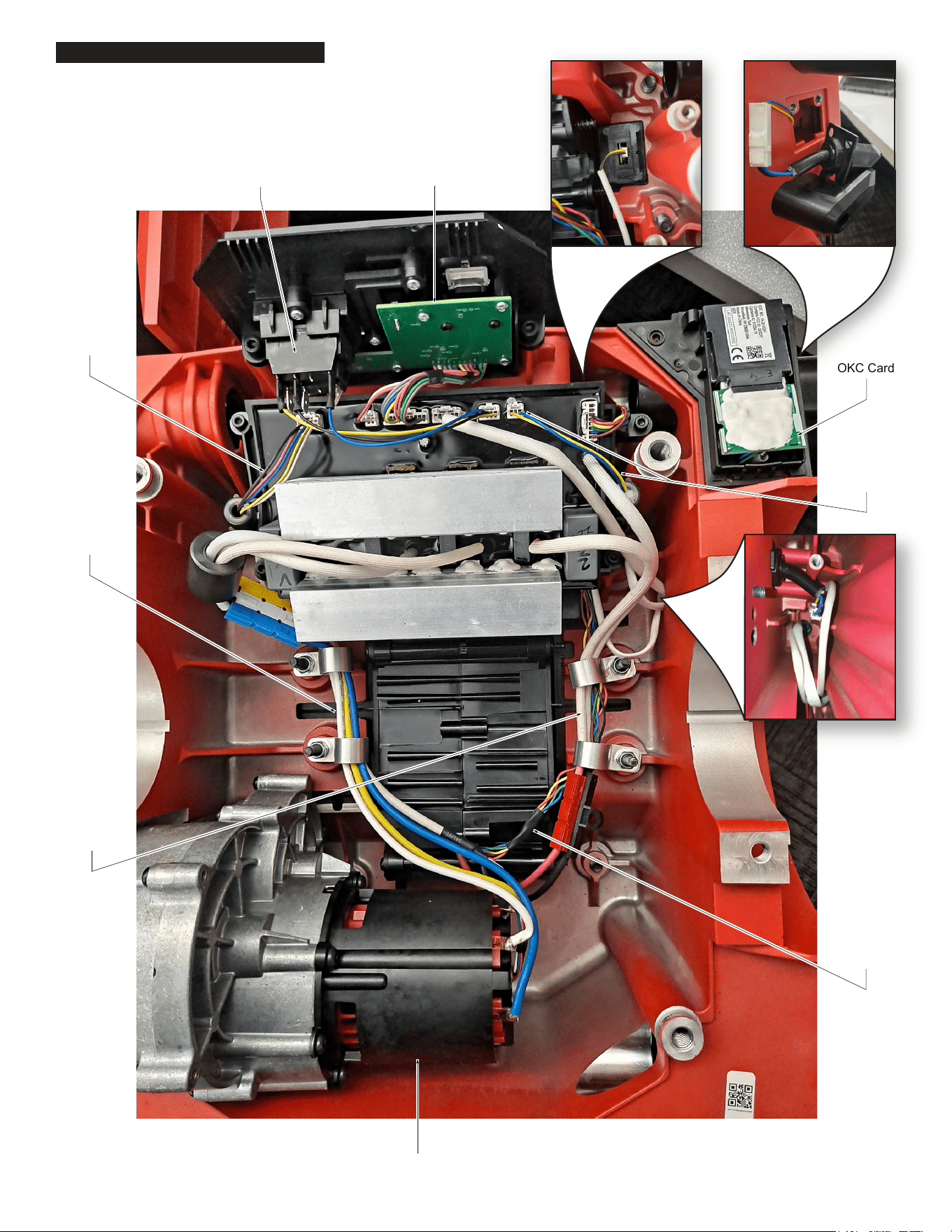
3-way
Switch
Motor
UI Board
Assembly
Hall Board
Signal Wire
Assembly
Motor
Power
Wire
Assembly
OKC Card
Trigger
Connector
Battery
Terminal
Power Wire
Assembly
Battery
Signal Wire
Assembly
Foot Pedal/
OKC Wiring
(underside)
Coin Cell
Foot Pedal Wiring
Install the electronics assembly as shown. Route wires around screw bosses
and into wire traps. Be sure all components are seated squarely and firmly
in place. Be sure there is no interference when installing the housing cover.
Wire Routing