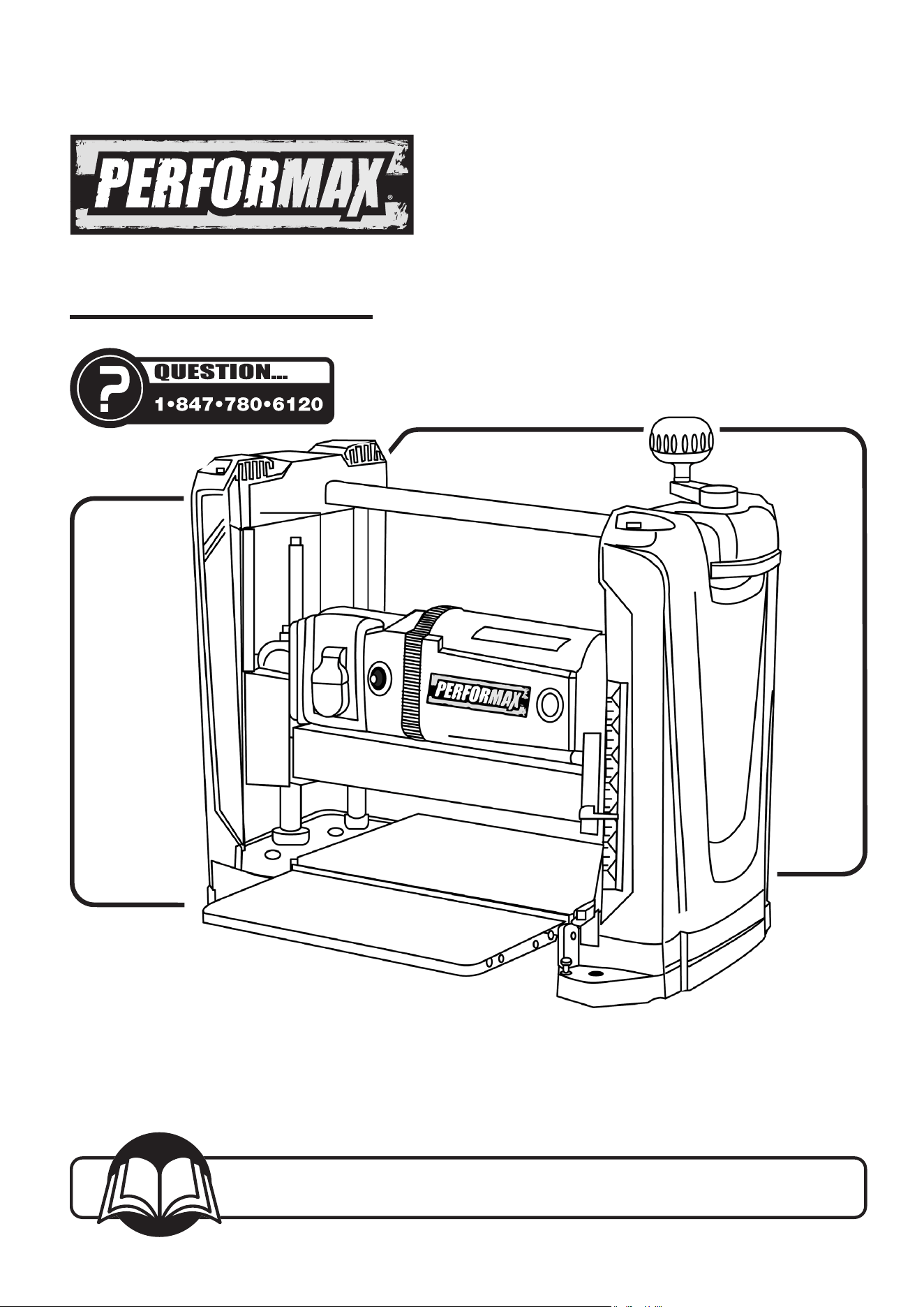
Owner's Manual
Model No. 240-3750
25-0630
You will need this manual for safety instructions, operating procedures, and warranty.
Put it and the original sales invoice in a safe, dry place for futurereference.
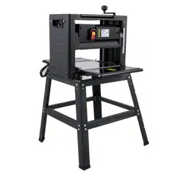
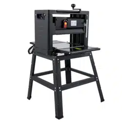
12-1/2" PLANER
2
Horsepower (Maximum Developed) ............... 2 HP
Voltage...................................... 120 V
Amperes ..................................... 15 A
Hertz ....................................... 60 Hz
Phase.......................................Single
Cutterhead RPM ...........................9,400 rpm
Table Size ...........................12-1/2"×9-5/16"
Blade Width..................................12mm
Maximum Depth of Cut .........................3/32"
Cuts per Minute ..............................18,800
MOTOR SPECIFICATIONS
Planer is supplied with a 2 HP motor installed.
The 120 Volt AC universal motor has the following
Specifications:
Horsepower (Maximum Developed) ............... 2 HP
Voltage...................................... 120 V
Amperes. ..................................... 15 A
Hertz.. ...................................... 60 Hz
Phase.......................................Single
TABLE OF CONTENTS PRODUCT SPECIFICATIONS
SECTION PAGE
SAFETY RULES / WARNINGS 3, 6
Work Preparation
Work Area Preparation
Tool Maintenance
Tool Operation
CONTENTS 4
Unpacking
ASSEMBLY 4-5
Install Dust Chute
Install Elevation Crank Handle
Power Source
Grounding Instructions
Extension Cords
Electrical Connections
OPERATION 6-8
Safety Precautions
Rollercase Height Adjustment
Depth of Cut
ON/OFF Switch
Circuit Breaker
Before Operating the Planer
MAINTENANCE 9
Check and Replace the Blades
Inspect and Replace the Motor Brushes
Adjust Rollercase Level
Replace V-Belt
Cleaning and Lubrication
TROUBLESHOOTING 10
NOTES 11
PARTS ILLUSTRATION & LIST 12-13
WARRANTY 15

SAFETY RULES
3
GENERAL SAFETY RULES
3
WARNING
For your own safety, read and understand all warnings and
operating instructions before using any tool or equipment.
WARNING
Some dust created by the operation of the power tool
contains chemicals known to the State of California to
cause cancer, birth defects or other reproductive harm. To
reduce your exposure to these chemicals, work in a well
ventilated area and work with approved safety equipment.
Always wear OSHA/NIOSH approved, properly fitting face
mask or respirator when using such tools.
WARNING
Failure to follow these rules may result in serious personal
injury. Remember that being careless for even a fraction of a
second can result in severe personal injury.
WORK PREPARATION
• Wear proper apparel. Do not wear loose clothing, gloves,
neckties, rings, bracelets or other jewelry which may get
caught in moving parts of the tool.
• Nonslip protective footwear is recommended.
• Wear protective hair covering to contain long hair.
• Wear eye and hearing protection. Always use safety
glasses. Eye protection equipment should comply with
ANSI Z87.1 standards. Hearing equipment should comply
with ANSI S3.19 standards.
• Wear face mask or dust mask if operation is dusty.
• Be alert and think clearly. Never operate power tools when
tired, intoxicated or when taking medications that cause
drowsiness.
WORK AREA PREPARATION
• Keep work area clean. Cluttered work areas and benches
invite accidents.
• Work area should be properly lighted.
• Do not use the Machine in a dangerous environment. The
use of power tools in damp or wet locations or in rain can
cause shock or electrocution.
• Three-prong electrical plug should be plugged directly into
properly grounded, three-prong receptacle.
• Use a proper extension cord. Make sure your extension
cord is in good condition and should have a grounding
prong and the three wires of extension cord should be of
the correct gauge.
• Keep children and visitors away. Your shop is a potentially
dangerous environment. Children and visitors can be injured.
• Make your workshop childproof with padlocks, master
switches or remove switch keys to prevent any unintentional
use of power tools.
TOOL MAINTENANCE
• Turn the Machine OFF, and disconnect the Machine from
the power source prior to inspection.
• Maintain all tools and Machines in peak condition. Keep
tools sharp and clean for best and safest performance.
• Follow instructions for lubricating and changing
accessories.
• Check for damaged parts. Check for alignment of moving
parts, binding, breakage, mounting and any other condition
that may affect tool's operation.
• Poorly maintained tools and Machines can further damage
the tool or Machine and/or cause injury.
• A guard or any other part that is damaged should be
repaired or replaced. Do not perform makeshift repairs.
TOOL OPERATION
• Avoid accidental start-up. Make sure that the tool is in the
OFF position before plugging in.
• Use the right tool for your job. Do not force your tool or
attachment to do a job for which it was not designed.
• Disconnect tool when changing parts.
• Don't force the workpiece on the Machine. Damage to the
Machine and/or injury may result.
• Never leave tool running unattended. Turn the power off
and do not leave tool until it comes to a complete stop.
• Do not overreach. Loss of balance can make you fall into a
working Machine, causing injury.
• Never stand on tool. Injury could occur if the tool tips, or if
you accidentally contact the cutting tool.
• Know your tool. Learn the tool’s operation, application and
specic limitations before using it.
• Use recommended accessories. Use of improper
accessories may cause damage to the Machine or injury to
the user.
• Handle workpiece correctly. Keep hands away from
moving parts.
• Turn tool off if it jams.
CAUTION
Think safety! Safety is a combination of operator common
sense and alertness at all times when tool is being used.
WARNING
Do not attempt to operate tool until it is completely
assembled according to the instructions.
SAVE ALL WARNINGS AND INSTRUCTIONS
FOR FUTURE REFERENCE
4
CONTENTS
CONTENTS
4
UNPACKING
• Check for freight damage before opening the
package. If freight damage is noticed, le a claim with
the carrier immediately.
• Check to ensure all parts are accounted for. If any
parts are missing, please contact the customer
service center at 1-847-780-6120.
• This Planer comes mostly assembled. It requires
some additional assembling, installation, and
adjustment before use.
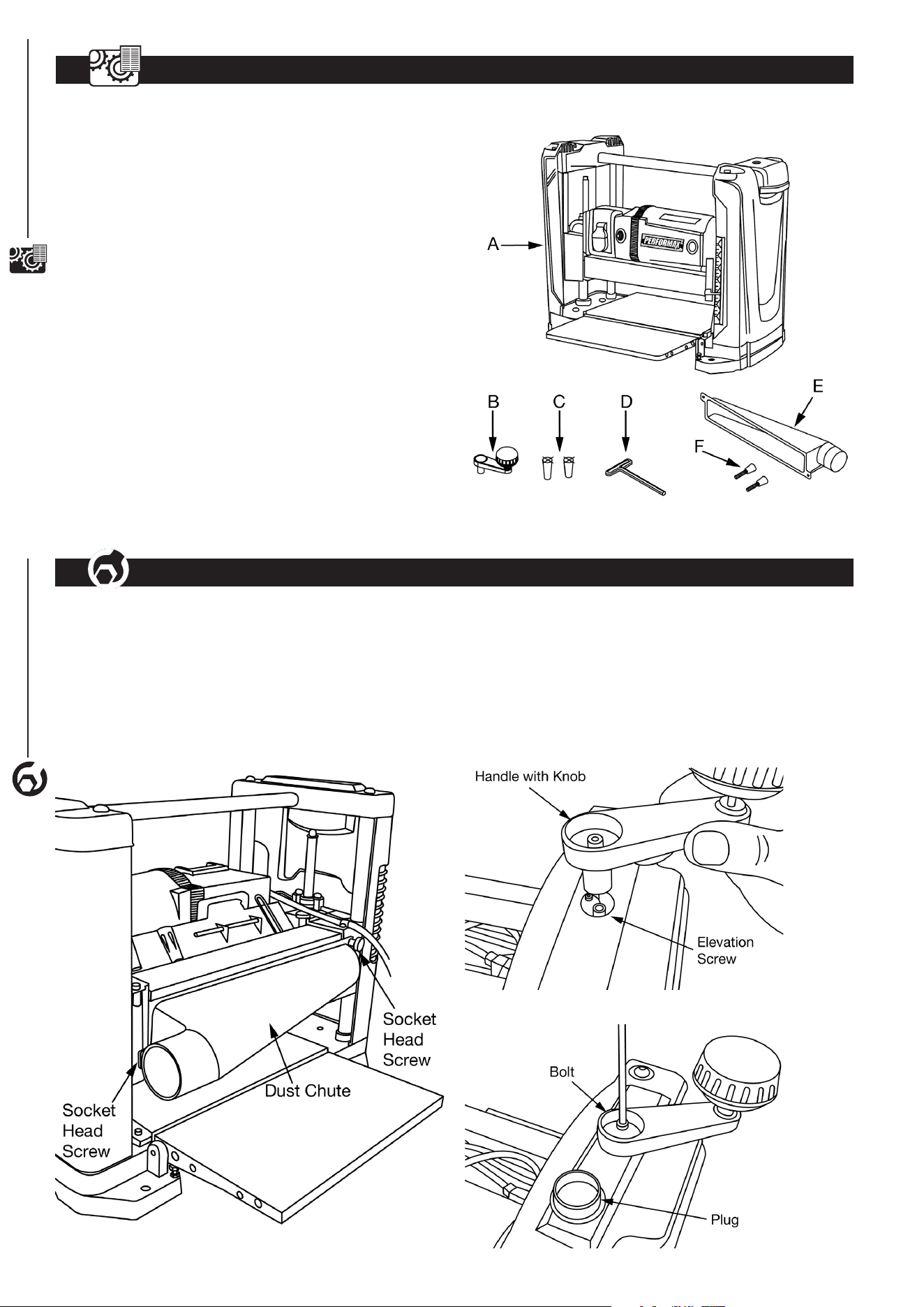
• Locate the following parts before assembling:
A Planer ..................................(1)
B Elevation Crank Handle Assembly ..........(1)
. . . . . . . . . . . . (including M5 bolt, at washer and plug)
C Magnet .................................(2)
D T-Wrench ...............................(1)
E Dust Chute ..............................(1)
F Socket Head Screw....................... (2)
Figure 1
ASSEMBLY
4
4
ASSEMBLY
INSTALL DUST CHUTE
• Planer is best used along with a dust collector. Dust chute
is included. The dust chute is mounted to the rollercase
using two socket head screws. The dust chute can be
mounted to direct chips to either side of the planer.
• After mounting, connect wet/dry vacuum hose to dust
chute. Be sure to turn the vacuum on before operating
theplaner.
Figure 2
INSTALL ELEVATION CRANK HANDLE
• The planer handle can be installed to the top-right of
the planer.
• Insert handle onto elevation screw top.
• Secure handle with bolt and at washer using the
enclosed wrench.
• Insert plug into handle.
Figure 3
Figure 4
ASSEMBLY
5
WARNING
Do not use the machine until it is completely assembled
and you have read and understood the entire operating
manuals.
• The machine must be installed in a well-lit area with correct
power supply.
• There must be enough clearance for the moving workpiece
during operation. There must be enough room for safe
operation of the machine.
POWER SOURCE
WARNING
Do not connect to the power source until the machine is
completely assembled.
The machine is wired for 120 Volts, 60 Hz alternating current.
Before connecting the machine to the power source, make
sure the switch is in the "OFF" position. Running the unit on
voltages which are not within range may cause overheating
and motor burn-out. Heavy loads require that voltage at motor
terminals be no less than the voltage specied on nameplate.
• Power supply to the motor is controlled by a locking rocker
switch. Remove the key to prevent unauthorizeduse.
GROUNDING INSTRUCTIONS
WARNING
Improper connection of equipment grounding conductor
can result in the risk of electrical shock.
• The machine should be grounded while in use to protect
operator from electrical shock.
• In the event of an electrical short circuit, grounding reduces
the risk of electrical shock by providing an escape wire for
the electricity.
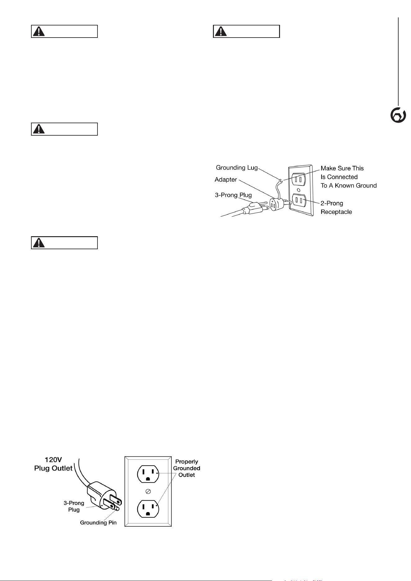
• This machine is equipped with an approved 3-conductor
cord rated at 120V and a 3-prong grounding type plug
(Figure 5) for your protection against shock hazards.
• Grounding plug should be plugged directly into a properly
installed and grounded 3-prong grounding-type receptacle,
as shown (Figure 5).
• The plug must be plugged into an outlet that is properly
installed and grounded in accordance with all local codes
and ordinances.
• Check with a qualied electrician or service personnel if
these instructions are not completely understood or if in
doubt as to whether the tool is properly grounded.
• Do not modify plug provided. If it will not t in outlet, have
proper outlet installed by a qualied electrician. Use only
3-wire extension cords, that have 3-prong grounding type
plugs and matching 3-conductor receptacles that accept
the machine's plug, as shown in Figure 5.
Figure 5
WARNING
Do not permit fingers to touch the terminals of plug when
installing or removing from outlet.
• Inspect tool cords periodically, and if damaged, have
repaired by an authorized service facility.
• The conductor with insulation having a green outer surface,
with or without yellow stripes, is the equipment-grounding
conductor. If repair or replacement of the electric cord or
plug is necessary, do not connect the green (or green and
yellow) wire to a live terminal.
A temporary 3-prong to 2-prong grounding adapter (see
Figure 6) may be used to connect this plug to a matching
2-conductor receptacle as shown in Figure 6. The temporary
adapter should be used only until a properly grounded outlet
can be installed by a qualied electrician.
Figure 6
In Canada, the use of temporary adapter is not permitted
by the Canadian Electric Code. Where permitted, the rigid
green tab or terminal on the side of the adapter must be
securely connected to a permanent electrical ground such
as a properly grounded water pipe, a properly grounded
outlet box or a properly grounded wire system.
• Many cover plate screws, water pipes and outlet boxes are
not properly grounded. To ensure proper ground, grounding
means must be tested by a qualied electrician.
EXTENSION CORDS
Use proper extension cords. Make sure the extension cord
is in good condition. Use only 3-wire extension cords that
have 3-prong grounding type plugs and 3-pole receptacles
which accept the tool plug. When using an extension cord,
make sure to use one heavy enough to carry the current of the
machine. An undersized cord will cause a drop in the voltage,
resulting in loss of power and overheating. Use the table to
determine the minimum wire size (A.W.G.) extension cord.
Extension Cord Length
Wire Size ................................... A.W.G.
Up to 25 ft.......................................18
25 to 50 ft.......................................16
NOTE: Extension cords over 50 ft. notrecommended.
ELECTRICAL CONNECTIONS
• Turn the switch off and disconnect the machine from power
source before performing any repair or maintenance work.
• Some electrical wiring and connection work must be performed
by a qualied electrician in accordance with local regulations.
• There is a green grounding wire fastened to the frame of the
machine to provide shock protection. Do not disconnect the
grounding wire from the frame.
• The motor is rated for used at 120 Volts.
• Connect this machine to 3-Conductor power outlet with
appropriate rating only.
• Use only 3-pronged extension power cord with appropriate
rating with this machine.
• When changing the power cord, use only 3-pronged power
cord with appropriate rating.
• The power switch is a single pole rocker switch with
locking mechanism. Remove the key when not in use to
prevent accidents.
6
OPERATION
OPERATION
6
WARNING
For your own safety, read the entire operating manual and
safety instructions before using this tool.
TOOL SPECIFIC SAFETY PRECAUTIONS
• Be aware of general power tool safety. Make sure all the
safety rules are understood.
• Disconnect the machine from power source whenever
adjusting or replacing any parts.
• Do not plug planer in unless switch is in the “OFF” position.
• Keep hands away from all moving parts.
• Wear eye protection or face shield during operation.
• Make sure all mobile parts move freely and are free from
interference.
• Keep blades sharp, aligned and properly attached
cutterhead.
• Properly secure the blades in the cutterhead.
• Never turn the machine “ON” with the workpiece contacting
the cutterhead.
• Never make cuts deeper than 3/32" (2.4mm) to prevent
kickback.
• Do not force cut. Slowing or stalling will overheat the motor.
• Do not perform planing on workpiece shorter than 15",
narrower than 3/4", wider than 12-1/2" or less than
1/8" thick.
• Properly support long or wide workpieces.
• Do not use a workpiece that is warped, contains knots, or
is embedded with foreign objects (nails, staples, etc.) to
prevent kickback.
• Do not feed a workpiece into the planer outfeed table.
• Do not allow anyone to stand or cross in line of cutterhead
rotation. Kickback or thrown debris will travel in this direction.
• Turn switch off and disconnect power whenever planer is
not in use.
• Keep planer maintained. Follow maintenance instructions.
WARNING
Turn the switch to the OFF position and disconnect the
machine from power source before any maintenance.
ROLLERCASE HEIGHT ADJUSTMENT
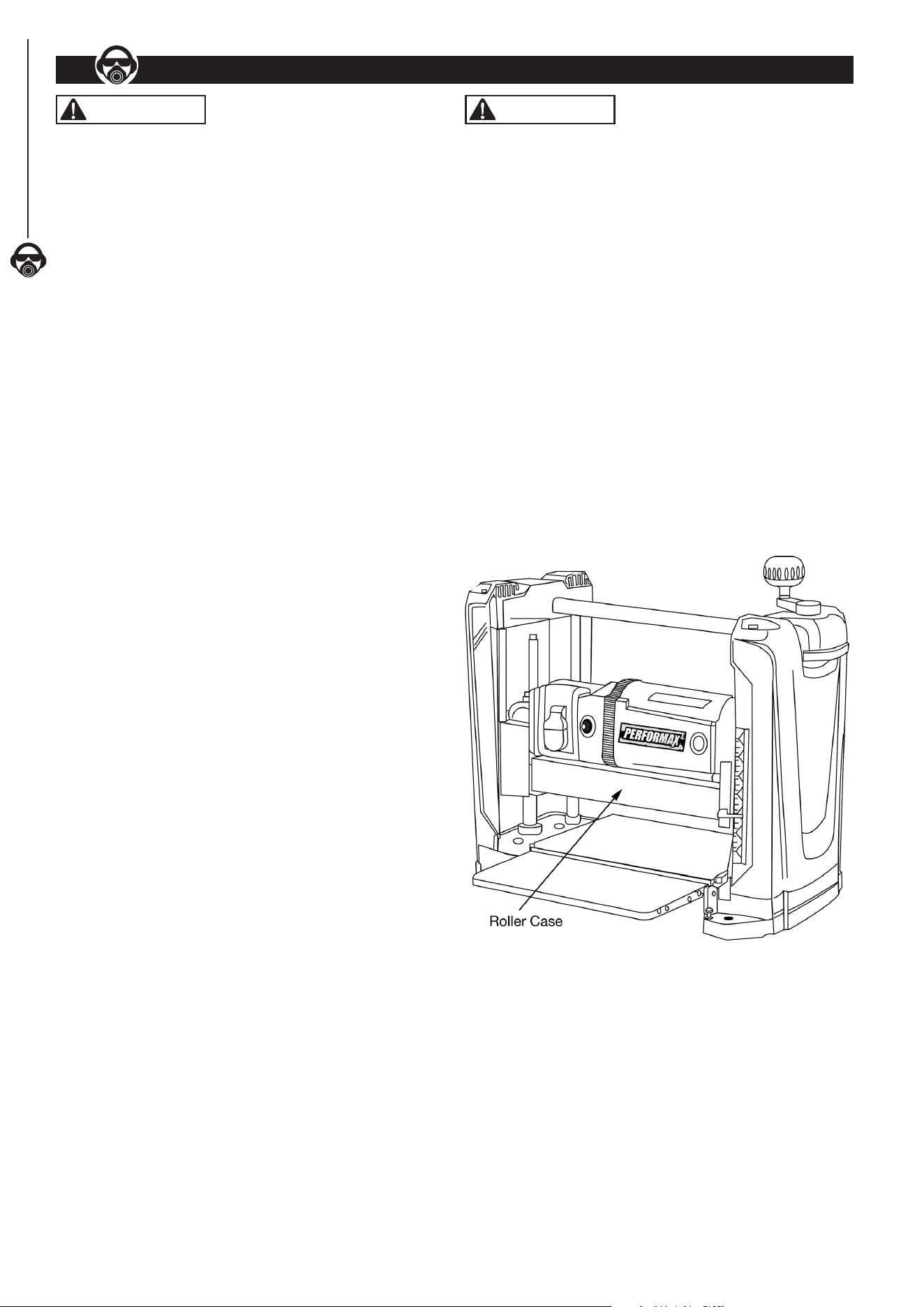
Refer to Figure 7
• Rollercase is the centerpiece of the planer machine. It
contains motor, cutterhead with blades, infeed and outfeed
rollers, dust collection assembly.
• The rollercase can be moved up or down precisely by
rotating the elevation crank handle on the top of planer.
One complete turn of elevation crank handle is equivalent
to 1/16" movement of rollercase in either direction.
• There is an elevation scale at the front of right side panel.
- It has a pointer with English and Metric scale. The
reading is the height of cutterhead from the table
platform. Therefore, the elevation scale setting
represents the approximate thickness of the
workpiece after planing.
• Elevation scale is calibrated in factory and should have
reasonable accuracy. For woodworking of precision, use of
calipers after each planing is recommended.
Figure 7
DEPTH OF CUT Refer to Figure 7
• The depth-of-cut is the thickness of wood material removed
from the surface of workpiece during each pass. The depth-
of-cut is determined by the relative position of the rollercase
to the top of workpiece.
• To protect long use life of motor and cutterhead unit, the
recommended maximum depths-of-cut are:
3/32" for workpiece up to 5" wide
1/16" for workpiece from 5" to 12-1/2" wide
OPERATION
7
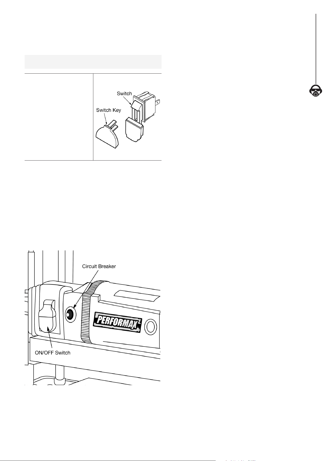
ON/OFF SWITCH
• The ON/OFF switch is located on the front of planer.
• To turn the machine ON, pull the switch to the up position.
• To turn the machine OFF, push the switch to the down
position.
NOTE: When the machine is not in use, the machine should
be locked in the “OFF” position to prevent unauthorized use.
• To lock the machine, turn
the switch to the “OFF”
position.
• Pull the key out. The
switch cannot be turned
on without the key.
• If the key is removed when
the switch is at the "ON"
position, the switch can be
turned off but cannot be
turned on again.
• To unlock, place the key
into the slot on switch unit
until it clicks.
Figure 8
CIRCUIT BREAKER
• This machine has a circuit breaker installed next to the main
power switch. The circuit breaker protects the motor unit
by shutting off the power supply when excessive electric
current is detected. If the circuit breaker is tripped, the
machine will not power on.
• Before resetting the circuit breaker, check motor, switch,
and line connection for short circuit or faulty components.
• To reset the circuit breaker, turn the switch to "OFF"
position. Then press the circuit breaker reset button next to
the main switch.
Figure 9
BEFORE OPERATING THE PLANER
• Understand the machine function and observe all the safety
measurement.
• In general, the desired depth-of-cut and nal thickness of
a workpiece are determined before planing. Since there is
a limit of maximum depth-of-cut, the workpiece may have
to be passed through the machine several times before
reaching the desired nal thickness.
• The rollercase has to be lowered manually before each
pass, if more than one pass is necessary.
• The planer machine setting involves readings of elevation
scale and operation of the rollercase elevation crank handle.
• The rollercase elevation crank handle controls rollercase
position in height and determines the amount of wood
material to be removed (depth-of-cut) in each pass.
Thickness of the remaining workpiece, after planing (nal
thickness), is observed in elevation scale.
• In general, thin depth-of-cut produces better outcome:
smooth surface, even thickness, less kickback, less snipe,
less wear on cutterhead and motor.
• Set thin depth-of-cut for hardwood, wide workpiece, and
uneven surface.
• This planer machine is designed to process natural wood
material only.
• Remove glue and any foreign objects from the workpiece
before planing.
• Avoid wood stock with many or large knots.
• Avoid wood stock with excessive twisting, cupping, or
bowing.
• If necessary, process one side with jointer machine rst
to obtain at least one at surface before using the planer
machine.
• For better outcome, plane both sides of wood board with
1/2 of depth removed from each side. This will produce two
smooth surfaces with equal amount of moisture content.
The board is less likely to warp when it dries naturally.
• Test cut with similar wood material for better accuracy.
• The minimum length of workpiece that can be processed is
15". The minimum width is 3/4". The minimum thickness is
1/8". (This is not to be confused with depth-of-cut.)
• The maximum width of workpiece that can be processed is
12-1/2". The maximum thickness is 6".
• To protect long use life of motor and cutterhead unit, the
recommended maximum depths-of-cut are:
3/32" for workpiece up to 5" wide
1/16" for workpiece from 5" to 12-1/2" wide
• Use additional roller stand for workpiece longer than 24".
8
OPERATION
OPERATE THE PLANER MACHINE
• Always use protective safety wear and observe safety rules.
• Never stand directly in the pathway of the workpiece,
including infeed and outfeed, to avoid injury. The operator
should stand on the side of the elevation crank handle.
• Feed the workpiece with the grain as much as possible.
That is, at the contact point, the grain points to the same
direction as that of rotating cutterhead. For this planer
machine, the grain direction on the top of the workpiece
should point towards the front of the machine.
• Place the workpiece on the infeed table. The surface to be
planed should be faced up.
• With the planer properly set up, turn the machine on.
• Hold the workpiece rmly and advance towards the infeed
roller slowly.
• Stop pushing or pulling the workpiece once it is engaged by
the infeed roller.
• The infeed roller will move the workpiece automatically
through the planer.
• For long workpiece, gently support the weight of the
workpiece while it is moved in and out of the planer to
stabilize the workpiece and decrease snipe.
• Move to the back of machine to receive the workpiece. Do
not pull.
• Use the return roller on the top of the planer to help
transport big workpiece back to infeed side. Use the entire
width of the cutterhead to avoid uneven wear of knives.
• For precision woodworking, measure thickness with
calipers after each planing.
WARNING
Turn the switch to the OFF position and disconnect the
machine from power source before any maintenance.
CHECK AND REPLACE THE BLADES
Refer to Figures 10 and 11
• Locate the blade cover on the back of planer. Loosen and
remove thumb screws from blade guard.
• Identify the cutterhead inside. Watch for TWO sharp blades
on the cutterhead.
• Without touching the blades, carefully turn the cutterhead
until it stops by the self-engaging latch.
Figure 10
Thumb Screws
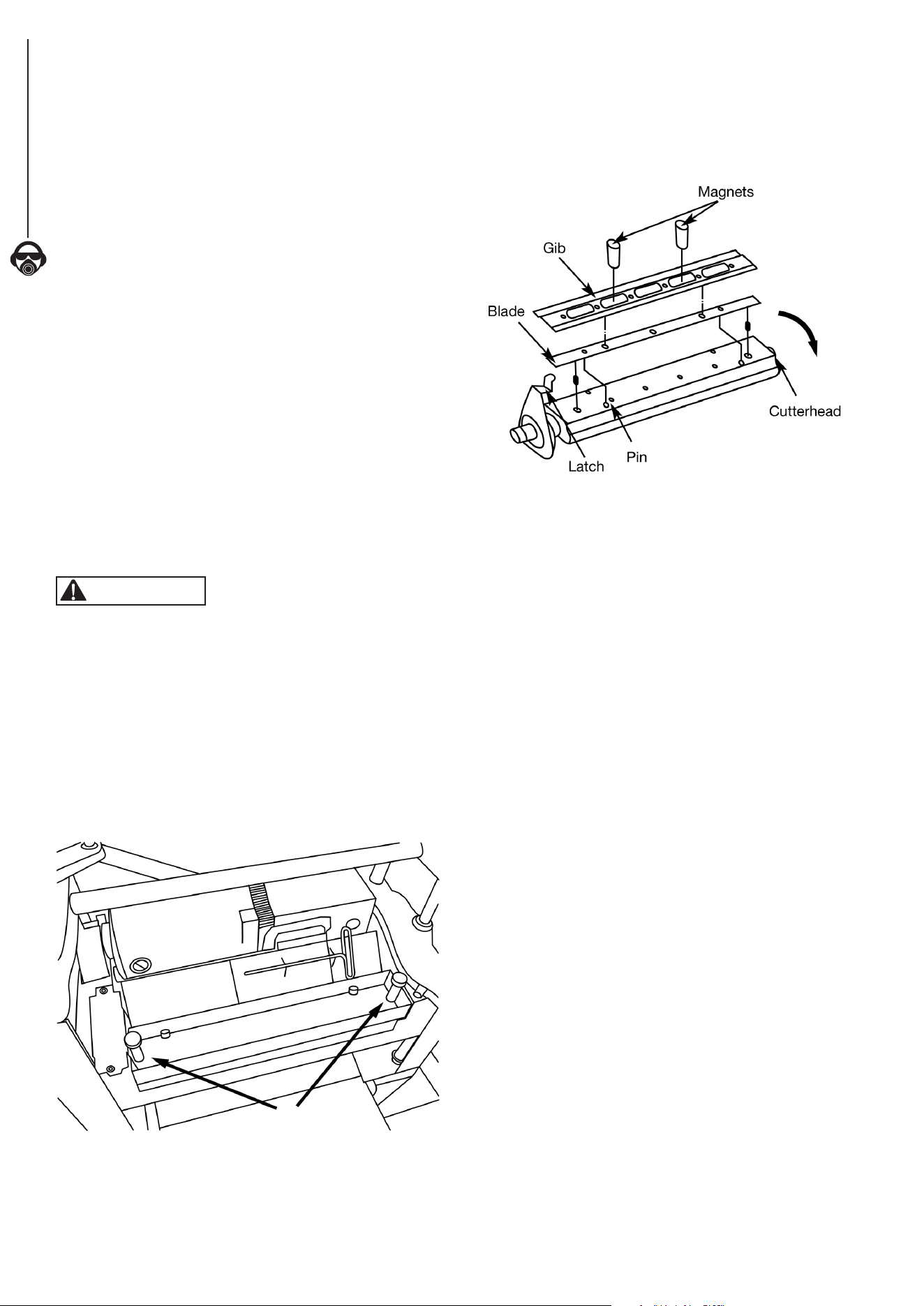
• Use T-wrench to remove 6 bolts on the blade assembly.
• Attach 2 provided magnets to the gib and carefully remove it.
• Attach 2 provided magnets to the blades and carefully
remove it.
Figure 11
• Check to see if the blade is dull, worn, nicked, torn, and
uneven. These can result in poor performance such as
fuzzy grain, chipped grain, raised grain, raised edge, and
uneven cut.
• Replace with new blades in pairs only. Never mix new
blade with old blade on the cutterhead. Never mix blades
with different degrees of wear. Never use a blade where
unbalanced wear from side to side is present.
• To replace with the new blade, use the 2 provided magnets
to transfer the blade onto the cutterhead.
• Position the blade so it sits securely on the two pins.
• Use the 2 provided magnets to transfer the gib onto the
blade. Position the gib so the 6 holes are aligned with the
holes on the cutterhead.
• Tighten and secure with 6 bolts.
• To access the other blade assembly, gently pull and hold
the latch on the side of cutterhead to release it.
• Once the cutterhead rotates, release the latch.
• Without touching the blades, carefully turn the cutterhead
until it stops the self-engaging latch.
• Repeat the same procedure to check and replace the
other blade.
• Replace the blade cover and secure with the two
thumb screws.

MAINTENANCE
9
MAINTENANCE
9
ADJUST ROLLERCASE LEVEL
Refer to Parts Illustration
The rollercase level is checked in factory and should work
properly. However, it can become out of alignment during
shipping and handling.
• If the rollercase is not level with the base, the depth-of-cut
will not be even from side to side. The end result is tapered
cut where the thickness on one side is different from the
other side. This can result from uneven wear of the blade as
well. Check to see blades are in good working order.
• Test run with two test pieces on right and left ends of the
planer to determine the amount needed to be corrected.
• Turn planer off and disconnect from power source. Carefully
place the planer on its back.
• Clamp vise pliers (not provided) on the left side of shaft (x
spacing) next to the gear.
• Remove retaining ring and disengage right gear from the
top gear.
• Slowly rotate handle to raise or lower rollercase Rollercase
will move by 0.006” with every turn of the gear by one tooth.
Move rollercase to the required distance to offset the taper.
• Re-engage and remove vise pliers.
• Sit the planer upright carefully.
• Test run the planer to check the rollercase level adjustment.
• Repeat the procedures if further adjustment is necessary.
REPLACE V-BELT
Refer to Parts Illustration
Inadequate tension in the V-belt will cause the belt to
slip from the motor pulley or drive pulley. A loose belt
must be replaced.
• Turn planer off and unplug from power source.
• Loosen and remove screws on right cap. Remove panel.
• Remove old belt by walking the belt from motor and drive
pulleys alternatively. Gently pull the belt outward while
turning the pulleys at the same time.
• Replace with new belt. Walk the belt on the pulleys in the
reverse manner as when removing the belt.
• Make sure belt is evenly seated all the way on the motor
and drive pulley grooves.
• Replace and secure right panel.
INSPECT AND REPLACE MOTOR BRUSHES
• Turn the switch to the “OFF” position and disconnect the
planer machine from the power source.
• Inspect the motor brushes after every 100 hours of use.
• Brush life varies, depending on the motor loads.
• Replace the motor brushes in set (two brushes) only.
• Replace with new parts only.
• To inspect motor brushes, unscrew brush caps on the sides
of motor. There are two caps, one on each side of motor.
• Remove brush assembly from motor.
• Replace motor brushes if the length of carbon has been
worn to less than 3/8", or if the springs are worn, or if the
motor does not run smoothly.
• Replace with new motor brush assembly.
• Replace the brush cap and tighten the screw.
• Repeat the same procedure on the other side of motor.
CLEANING AND LUBRICATION
• Vacuum the planer machine to remove wood chips, saw
dust, and debris.
• Use a cleaning solution (not included) to remove resin and
grease residue.
• Check and empty dust collection bag.
• Remove saw dust, wood chips, and grease from chains
and gears.
• The bearings in motor and cutterhead units are permanently
sealed in factory and should require no further lubrication.
• Three components require regular lubrication: rollercase
elevation screws (2x), the columns (4x), and the feed roller
chain drive. Remove the top and both side panels to access
these components.
• Remove old grease residues, with minerals spirits if
necessary, then apply a coat of light grade multi-purpose
grease (not included).
• Chain drive should be cleaned before lubrication. Use spray
oil (not included) to lubricate the chain. The chain should
be wiped dry after the lubricant has had enough time to
penetrate the links.
• The work table and extension table can be coated with very
thin lubricating wax (not included) to protect the surface
from rust and to facilitate smooth feed during operation.

10
TROUBLESHOOTING
TROUBLESHOOTING
10
Follow all safety precautions when servicing unit
SYMPTOM POSSIBLE CAUSE(S) CORRECTIVE ACTION
Motor will not start
1. Low voltage Check power supply for proper voltage
2. Short circuit in line cord or plug Inspect line cord and plug for faulty insulation or shorted connection
3. Short circuit in motor Inspect connection on motor
4. Open circuit or loose connection in motor Inspect connection on motor
5. Incorrect fuses or circuit breakers Replace with correct fuses or circuit breakers
6. Defective switch Replace switch
7. Motor overload resulting in tripped
circuit breaker
Turn the Planer off and reset overload protection
Motor stalls or fails to
reach maximum speed
1. Power overload Reduce workload on the power supply
2. Low voltage from power supply Check power supply for proper voltage
3. Undersized extension cord Use extension cord adequate in size and/or use a shorter cord
4. Motor overload Reduce load on motor
5. Short circuit or loose connection
in motor
Inspect the connection in motor for loose or shorted connection
6. Incorrect fuses or circuit breakers Replace with correct fuses or circuit breakers
7. Wood chips clogged Inspect chip blower assembly—Remove wood chips
Motor overheats
1. Motor overload Reduce load on motor—Turn off the Planer until motor cools down
2. Excessive dust build-up resulting in
decreased air circulation
Remove built up dust
Frequent tripping of
circuit breaker
1. Motor overload Reduce load on motor
2. Inadequate capacity of circuit breaker Replace with correct circuit breaker
3. Circuit overload Reduce circuit load
4. Dull blades Replace or sharpen blades
Snipe
1. Inadequate support of workpiece Support long workpiece with additional platform
2. Dull blades Replace or sharpen blades
3. Uneven force on cutterhead Push workpiece gently during operation
4. Rollercase is not level with Planer base Adjust table and rollercase level properly
5. Workpiece is not butted properly Butt, end-to-end, each workpiece as it passes through Planer
Surface not smooth
1. Dull blades Replace or sharpen blades
2. Fuzzy grain due to high moisture content
in wood
Use dry wood
3. Tor n grain due to blades cutting
against grain
Change direction and feed workpiece along grain
4. The cut is too deep Decrease depth of cut
Uneven thickness form
side-to-side
Rollercase is not positioned level with
Planer base
Adjust table and rollercase level properly
Difficulties in adjusting
rollercase elevation
1. Worn elevation screws Replace elevation screws
2. Dirty elevation screws or columns Clean and lubricate elevation screws and columns
3. Dirty chains or sprockets Clean and lubricate chains and sprockets
4. Rollercase is not positioned level with
Planer base
Adjust table and rollercase level properly
5. Friction between rollercase and covers Clean and adjust rollercase or covers
Wood thickness
does not match
depth of cut setting
Indicator is not set correctly Adjust and tighten indicator properly
Chain jumping
1. Worn chains Replace chains
2. Worn sprockets Replace sprockets
Belt slipping Belt is loose Replace V-Belt
Excessive fan noise
1. Loose fan assembly Inspect fan assembly and tighten fan screws
2. Large wood chips stuck in fan housing Turn Planer OFF—Remove blade guard, and clean the chamber

NOTES
11
NOTES
11
12
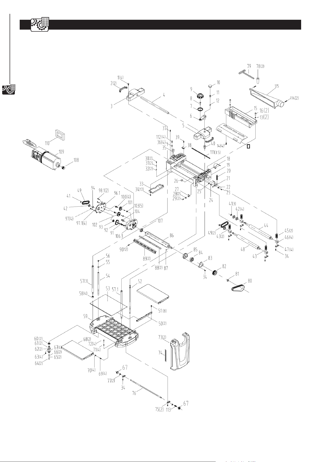
PARTS ILLUSTRATION
12-1/2" PLANER PARTS ILLUSTRATION
12

PARTS LIST
13
Key
No.
Part No. Description Specication
Qty
1
PL1250001 Pan Head Screw M8*16 4
2
PL1251001 Portable Sheath 2
3
PL1251002 Left Cap 1
4
PL1251003 Roller
Φ20×2.0T×389L
1
5
PL1251004 Right Cap 1
6
PL1250004.6 Crank Arm 1
7
PL1250004.5 Handle 1
8
PL1250004.4 Handle Shaft 1
9
PL1250004.3 Handle Cap 1
10
PL1250004.1 Plug 1
11
PL1251005 Socket Head Screw M5*20 1
12
PL1251006 Washer
Φ5
1
13
PL1251007 Washer
Φ5×Φ14×0.8t
2
14
PL1250012 Tapping Screw ST4.8×10L 4
15
PL1251009 Dust Hood 1
16
PL1251010 Socket Head Screw M5*16 2
17
PL1251012 Dust Chute 1
18
PL1250041 Belt Guard 1
19
PL1251008 Carriage Frame 1
20
PL1250064 Spring 1
21
PL1250065 Cutterhead Lock Plate 1
22
PL1250066 Spacer 1
23
PL1250067 Socket Head Screw M5*16 1
24
PL1251014 Hex Bolt M8*20 1
25
PL1251015 Flat Washer
Φ8
1
26
PL1251016 Spacer 1
27
PL1251017 Pointer 1
28
PL1251018 Flat Washer
Φ3
2
29
PL1251019 Cross Head Screw M3*6 2
30
PL1251020 Cross Head Screw M5*8 2
31
PL1251021 Spring Washer
Φ5
2
32
PL1250048 Serrated Washer
Φ5.3*Φ10
2
33
PL1251022 Gearbox Cover 1
34
PL1251023 Socket Head Screw M5*12 16
35
PL1250088 Elevating Nut (L.h.) 1
36
PL1250090 Flat Washer
Φ6.3*15*2T
4
37
PL1250040 Set Screw M5*10 1
38
PL1250039 Cord Clamp UC-1.5 1
39
PL1250038 Cross Head Screw M5*10 1
40
PL1250091 Elevating Nut (R.h.) 1
41
PL1250080 Extend Ret Ring
Φ15.7
3
42
PL1250021 Sprocket 4
43
PL1251024 Spring (Infeed) 2
44
PL1251025 Outfeed Roller 1
45
PL1251026 Spring (Outfeed) 2
46
PL1251027 Bearing Block 4
47
PL1251028 Retainer 4
48
PL1251029 Infeed Roller 1
49
PL1250081 Chain #410-26 2
50
PL1251030 Guide 2
51
PL1251031 Socket Head Screw M5*10 8
52
PL1251032 Elevating Screw (R.h.) 1
53
PL1251033 Platen 1
54
PL1250093 Elevating Screw (L.h.) 1
55
PL1251034 Flat Washer
Φ6
1
56
PL1250086 Socket Head Screw M6*10 1
57
PL1250092 Column 3
57.1
PL1250092.1 Subsidiary Column 1
58
PL1250100 Hex Nut M12 4
59
PL1251035 Base 1
60
PL1250102 Bearing 6000ZZ 2
Key
No.
Part No. Description Specication
Qty
61
PL1250105 Spacer 2
62
PL1250103 Retainer 2
63
PL1251036 Pan Head Screw M5*12 4
64
PL1250109 Socket Head Screw M4*12 2
65
PL1250108 Spring Washer
Φ4
2
66
PL1250107 Flat Washer
Φ4
2
67
PL1250106 Gear 4
68
PL1251037 Extend Table Ass. 2
69
PL1251038 Adjust Screw 4
70
PL1251039 Hex Nut M10 4
71
PL1250099 Hex Nut M6 4
72
PL1250098 Hex Bolt M6*20 4
73
PL1251040 Side Cover 2
74
PL1250122 Scale 22x181 1
75
PL1250117 Support 2
76
PL1251041 Shaft 1
77
PL1250120 Extend Ret Ring
Φ10
2
78
PL1250125 Magnet 2
79
PL1250126 Hex Wrench M4×130×70 1
80
PL1250062 Belt 135J6 1
81
PL1251042 Hex Nut M16 1
82
PL1250061 Pulley 1
83
PL1251043 Bearing Cover 1
84
PL1251044 Bearing 6204 1
85
PL1251045 Bearing Seat 1
86
PL1251046 Cutterhead 1
87
PL1250056 Key A5*12 1
88
PL1250053 Blade 2
89
PL1250052 Gib 2
90
PL1250057 Pan Head Screw M6*16 12
91
PL1250026 Shaft 1
92
PL1250027 Gear 70T 1
93
PL1250025 Bearing 6002-2Z 1
94 PL1250022 Spacer 1
96.1 PL1251054 Gear Cover 1
97 PL1250019 Socket Head Screw M5*35 4
97.1 PL1251055 Elasticity Spring 4
98.1 PL1251056 Socket Head Screw M5XP0.8X12L 2
100 PL1251049 Washer
Φ8xΦ14x0.1
4
101 PL1250029 Gear 52T+12T 1
102 PL1250028 Gear 58T+12T 1
103 PL1250030 Bushing 5
104 PL1250032 Pinion 1
106.1 PL1251057 Gear Outside Box 1
107 PL1250033 Bearing 6203-2Z 1
108 PL1251051 Motor Pulley 1
109 PL1251052 Motor 1
110 PL1250068.2 Sponge 140×60×90 1
111 PL1250016 Sponge 320*10*8 3.5
112 PL1250089 Socket Head Screw M6*P1*16L 4
113 PL1251053 Spring 1
114 PL1251058 Socket Head Screw M6*14 2
115 PL1251059 Dust Adapter 1
12-1/2" PLANER PARTS LIST
13


PERFORMAX
®
12-1/2" PLANER WARRANTY
15
2-YEAR LIMITED WARRANTY:
This PERFORMAX
®
brand power tool carries a 2-Year Limited Warranty to the original purchaser. If, during normal
use, this PERFORMAX power tool breaks or fails due to a defect in material or workmanship within two (2) years
from the date of original purchase, simply bring this tool with the original sales receipt back to your nearest
MENARDS
®
retail store. At its discretion, PERFORMAX agrees to have the tool or any defective part(s) repaired or
replaced with the same or similar PERFORMAX product or part free of charge, within the stated warranty period,
when returned by the original purchaser with original sales receipt. Not withstanding the foregoing, this limited
warranty does not cover any damage that has resulted from abuse or misuse of the Merchandise. This warranty:
(1) excludes expendable parts including but not limited to blades, brushes, belts, bits, light bulbs, and/or batteries;
(2) shall be void if this tool is used for commercial and/or rental purposes; and (3) does not cover any losses,
injuries to persons/property or costs. This warranty does give you specic legal rights and you may have other
rights, which vary from state to state. Be careful, tools are dangerous if improperly used or maintained. Seller’s
employees are not qualied to advise you on the use of this Merchandise. Any oral representation(s) made will not
be binding on seller or its employees. The rights under this limited warranty are to the original purchaser of the
Merchandise and may not be transferred to any subsequent owner. This limited warranty is in lieu of all warranties,
expressed or implied including warranties or merchantability and tness for a particular purpose. Seller shall not
be liable for any special, incidental, or consequential damages. The sole exclusive remedy against the seller will
be for the replacement of any defects as provided herein, as long as the seller is willing or able to replace this
product or is willing to refund the purchase price as provided above. For insurance purposes, seller is not allowed
to demonstrate any of these power tools foryou.
For questions / comments, technical assistance or repair parts
Please Call Toll Free at: 1-847-780-6120 (M-F 9am – 5pm)
SAVE YOUR RECEIPTS. THIS WARRANTY IS VOID WITHOUTTHEM.
15
WARRANTY

Menard,Inc.
Eau Claire, WI 54703