Important Safety Instructions
The following symbols and labels are used throughout this
manual to indicate immediate or potential safety hazards. It
is the owner’s and installer’s responsibility to read and comply
with all safety information and instructions accompanying
these symbols. Failure to heed safety information increases
the risk of personal injury, property damage, and/or product
damage.
CONDENSING UNIT
HEAT PUMP
INSTALLATION & SERVICE REFERENCE
© 2020-2022
Daikin Comfort Technologies Manufacturing, L.P.
19001 Kermier Rd., Waller, TX 77484
www.goodmanmfg.com -or- www.amana-hac.com
P/N: IOG-4009M Date: August 2022
HIGH VOLTAGE!
D
ISCONNECT
ALL
POWER
BEFORE
SERVICING
.
M
ULTIPLE
POWER
SOURCES
MAY
BE
PRESENT
. F
AILURE
TO
DO
SO
MAY
CAUSE
PROPERTY
DAMAGE
,
PERSONAL
INJURY
OR
DEATH
.
WARNING
S
CROLL
EQUIPPED
UNITS
SHOULD
NEVER
BE
USED
TO
EVACUATE
THE
AIR
CONDITIONING
SYSTEM
. V
ACUUMS
THIS
LOW
CAN
CAUSE
INTERNAL
ELECTRICAL
ARCING
RESULTING
IN
A
DAMAGED
OR
FAILED
COMPRESSOR
.
CAUTION
Shipping Inspection
Always keep the unit upright; laying the unit on its side or top
may cause equipment damage. Shipping damage, and sub-
sequent investigation is the responsibility of the carrier. Verify
the model number, specications, electrical characteristics,
and accessories are correct prior to installation. The distributor
or manufacturer will not accept claims from dealers for trans-
portation damage or installation of incorrectly shipped units.
Codes & Regulations
This product is designed and manufactured to comply with
national codes. Installation in accordance with such codes
and/or prevailing local codes/regulations is the responsibility
of the installer. The manufacturer assumes no responsibility
for equipment installed in violation of any codes or regulations.
Rated performance is achieved after 20 hours of operation.
Rated performance is delivered at the specied airow. See
outdoor unit specication sheet for split system models or
product specication sheet for packaged and light commercial
models. Specication sheets can be found at
www.goodmanmfg.com for Goodman
®
brand products or
www.amana-hac.com for Amana
®
brand products. Within
either website, please select the residential or commercial
products menu and then select the submenu for the type of
product to be installed, such as air conditioners or heat pumps,
to access a list of product pages that each contain links to
that model’s specication sheet.
The United States Environmental Protection Agency
(EPA) has issued various regulations regarding the in-
troduction and disposal of refrigerants. Failure to follow
these regulations may harm the environment and can
lead to the imposition of substantial nes.
ONLY PERSONNEL THAT HAVE BEEN TRAINED TO INSTALL, ADJUST,
SERVICE, MAINTENANCE OR REPAIR
(HEREINAFTER, “SERVICE”) THE EQUIPMENT SPECIFIED IN THIS MANUAL
SHOULD
SERVICE THE EQUIPMENT. THE MANUFACTURER WILL NOT BE RESPON-
SIBLE FOR ANY INJURY OR PROPERTY DAMAGE ARISING FROM IMPROP-
ER SERVICE OR SERVICE PROCEDURES. IF YOU SERVICE THIS UNIT, YOU
ASSUME RESPONSIBILITY FOR ANY INJURY OR PROPERTY
DAMAGE WHICH MAY RESULT. IN ADDITION, IN
JURISDICTIONS THAT REQUIRE ONE OR MORE LICENSES TO SERVICE THE
EQUIPMENT SPECIFIED IN THIS
MANUAL, ONLY LICENSED PERSONNEL SHOULD SERVICE THE EQUIP-
MENT.
IMPROPER INSTALLATION, ADJUSTMENT, SERVICING, MAINTENANCE
OR REPAIR OF THE EQUIPMENT SPECIFIED IN THIS MANUAL, OR AT-
TEMPTING TO INSTALL, ADJUST, SERVICE OR REPAIR THE EQUIPMENT
SPECIFIED IN THIS MANUAL WITHOUT PROPER TRAINING MAY RESULT
IN PRODUCT DAMAGE, PROPERTY DAMAGE, PERSONAL
INJURY OR DEATH.
WARNING
WARNING
DO NOT BYPASS SAFETY DEVICES
19001 Kermier Rd., Waller, TX 77484
www.goodmanmfg.com • www.amana-hac.com
© 2021-2022 Daikin Comfort Technologies Manufacturing, L.P.
is a registered trademark of Maytag Corporation or its related companies
and is used under license. All rights reserved.
2
THIS UNIT IS EQUIPPED WITH A 24 VAC TRANSFORMER THAT POWERS
THE HEAT PUMP CONTROL BOARD. WHEN INSTALLED AS A
COMMUNICATING SYSTEM, ONLY 2 WIRES
ARE
NEEDED BETWEEN
INDOOR AND OUTDOOR EQUIPMENT. HOWEVER, WHEN INSTALLED AS
A NON-COMMUNICATING (LEGACY) SYSTEM, THE TRANSFORMER
WIRING (LOW VOLTAGE AND LINE VOLTAGE) MUST BE DISCONNECTED.
R
EFER TO THE LOW VOLTAGE WIRING SECTION FOR MORE DETAILS.
NOTICE
Should you have any questions please contact the local oce
of the EPA.
If replacing a condensing unit or air handler, the system must
be manufacturer approved and Air Conditioning, Heating and
Refrigeration Institute (AHRI) matched. NOTE: Installation of
unmatched systems is strongly discouraged.
Outdoor units are approved for operation above 55°F in
cooling mode. Communicating units are equipped with two
speed of ECM fan motors and are not approved for use with
low ambient kits.
Damage to the unit caused by operating the unit in a structure
that is not complete (either as part of new construction or
renovation) is not covered by the warranty.
Features
This heat pump is part of a ComfortBridge™ control system
designed to more efficiently control heat gain/loss with
better eciency and achieve targeted comfort conditions.
The system utilizes digital linkage between the indoor and
outdoor equipment and can be controlled by any single-stage
thermostat. The ComfortBridge™ control system reduces the
number of required thermostat wires, provides additional setup
features and enhanced active diagnostics through Bluetooth
connectivity with the downloadable CoolCloud™ app.
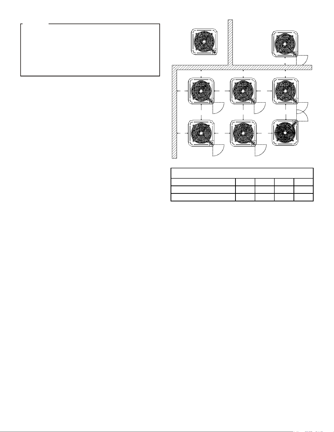
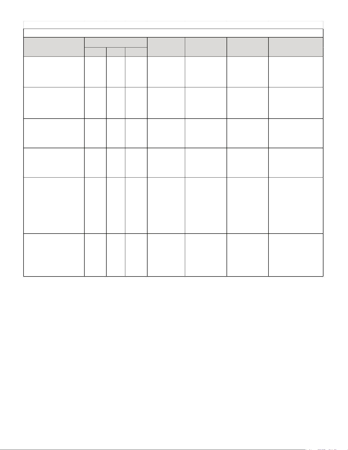
Installation Clearances
Special consideration must be given to location of the con-
densing unit(s) in regard to structures, obstructions, other
units, and any/all other factors that may interfere with air
circulation. Where possible, the top of the unit should be
completely unobstructed; however, if vertical conditions re-
quire placement beneath an obstruction there should be a
minimum of 60 inches between the top of the unit and the
obstruction(s). The specied dimensions meet requirements
for air circulation only. Consult all appropriate regulatory codes
prior to determining nal clearances.
Another important consideration in selecting a location for the
unit(s) is the angle to obstructions. Either side adjacent the
valves can be placed toward the structure provided the side
away from the structure maintains minimum service clearance.
Corner installations are strongly discouraged.
OK!
OK!
AA AA
A
A
CC
C
C
OK!
OK!
OK!
OK!
NOT
RECOMMENDED
AA
AA
AA
AA
AA
B B B
B
Model Type
A
B
C
AA
Residential
10"
10"
18"
20"
Light Commercial
12" 12" 18"
24"
Minimum Airflow Clearance
This unit can be located at ground oor level or on at roofs. At
ground oor level, the unit must be on a solid, level foundation
that will not shift or settle. To reduce the possibility of sound
transmission, the foundation slab should not be in contact
with or be an integral part of the building foundation. Ensure
the foundation is sucient to support the unit. A concrete slab
raised above ground level provides a suitable base.
Rooftop Installations
If it is necessary to install this unit on a roof structure, ensure
the roof structure can support the weight and that proper
consideration is given to the weather-tight integrity of the roof.
Since the unit can vibrate during operation, sound vibration
transmission should be considered when installing the unit.
Vibration absorbing pads or springs can be installed between
the con-densing unit legs or frame and the roof mounting
assembly to reduce noise vibration.
NOTE: These units require special location consideration
in areas of heavy snow accumulation and/or areas with
prolonged continuous subfreezing temperatures. Heat pump
unit bases have cutouts under the outdoor coil that permit
drainage of frost accumulation. Situate the unit to permit
free unobstructed drainage of the defrost water and ice. A
minimum 3” clearance under the outdoor coil is required in
the milder climates.
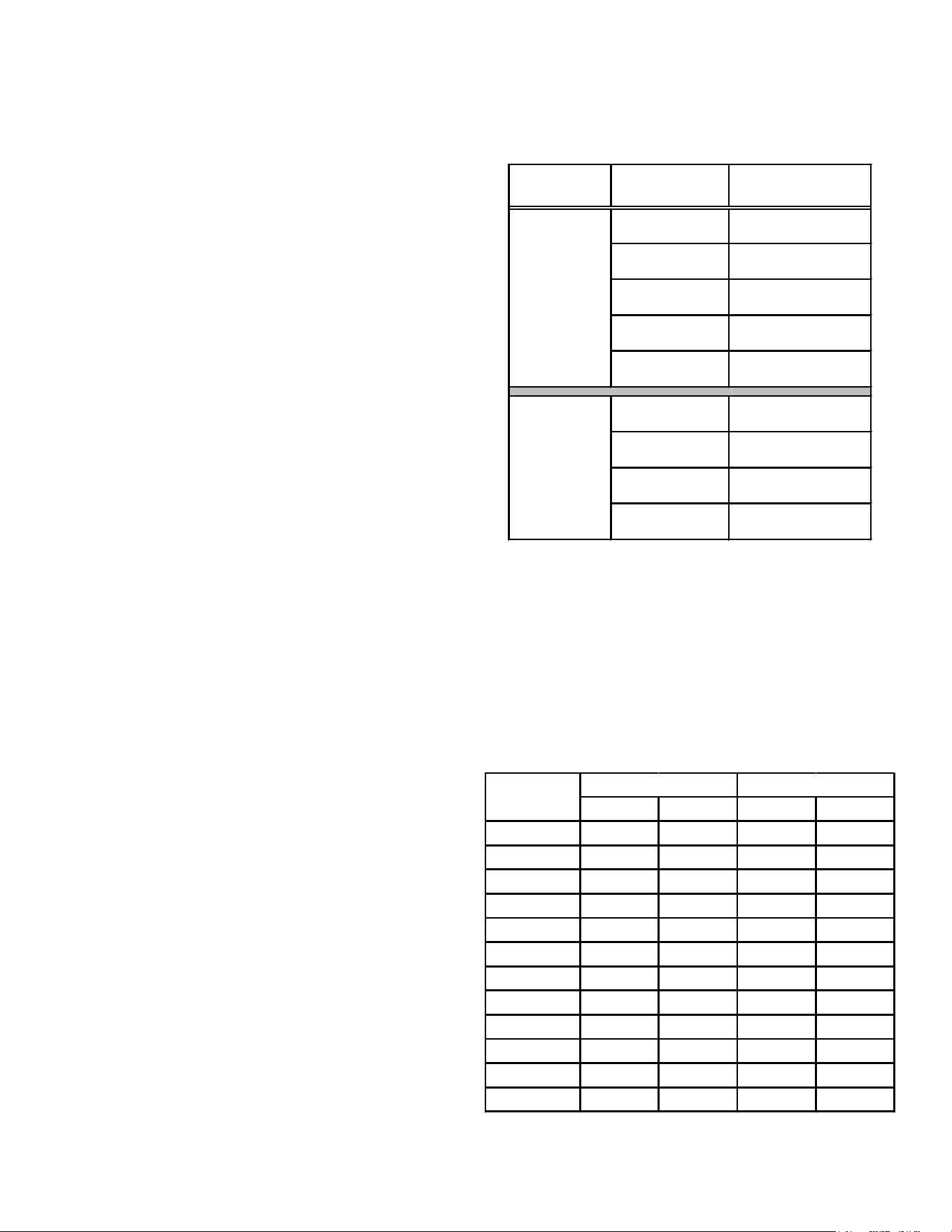
In more severe weather locations, it is recommended that the
unit be elevated to allow unobstructed drainage and air ow.
The elevation minimums at right are recommended:

3
Design Temperature
Suggested Minimum Elevation
+15° and above
2 1/2"
-5° to +14°
8"
below -5°
12"
Safe Refrigerant Handling
While these items will not cover every conceivable situation,
they should serve as a useful guide.
T
O
AVOID
POSSIBLE
INJURY
,
EXPLOSION
OR
DEATH
,
PRACTICE
SAFE
HANDLING
OF
REFRIGERANTS
.
WARNING
R
EFRIGERANTS
ARE
HEAVIER
THAN
AIR
. T
HEY
CAN
“
PUSH
OUT
”
THE
OXYGEN
IN
YOUR
LUNGS
OR
IN
ANY
ENCLOSED
SPACE
. T
O
AVOID
POSSIBLE
DIFFICULTY
IN
BREATHING
OR
DEATH
:
• N
EVER
PURGE
REFRIGERANT
INTO
AN
ENCLOSED
ROOM
OR
SPACE
. B
Y
LAW
,
ALL
REFRIGERANTS
MUST
BE
RECLAIMED
.
• I
F
AN
INDOOR
LEAK
IS
SUSPECTED
,
THOROUGHLY
VENTILATE
THE
AREA
BEFORE
BEGINNING
WORK
.
• L
IQUID
REFRIGERANT
CAN
BE
VERY
COLD
. T
O
AVOID
POSSIBLE
FROST
BITE
OR
BLINDNESS
,
AVOID
CONTACT
AND
WEAR
GLOVES
AND
GOGGLES
. I
F
LIQUID
REFRIGERANT
DOES
CONTACT
YOUR
SKIN
OR
EYES
,
SEEK
MEDICAL
HELP
IMMEDIATELY
.
• A
LWAYS
FOLLOW
EPA
REGULATIONS
. N
EVER
BURN
REFRIGERANT
,
AS
P
OISONOUS
GAS
WILL
BE
PRODUCED
.
WARNING
T
O
AVOID
POSSIBLE
EXPLOSION
:
• N
EVER
APPLY
FLAME
OR
STEAM
TO
A
REFRIGERANT
CYLINDER
. I
F
YOU
MUST
HEAT
A
CYLINDER
FOR
FASTER
CHARGING
,
PARTIALLY
IMMERSE
IT
IN
WARM
WATER
.
• N
EVER
FILL
A
CYLINDER
MORE
THAN
80%
FULL
OF
LIQUID
REFRIGERANT
.
• N
EVER
ADD
ANYTHING
OTHER
THAN
R-22
TO
AN
R-22
CYLINDER
OR
R-
410A
TO
AN
R-410A
CYLINDER
. T
HE
SERVICE
EQUIPMENT
USED
MUST
BE
LISTED
OR
CERTIFIED
FOR
THE
TYPE
OF
REFRIGERANT
USED
.
• S
TORE
CYLINDERS
IN
A
COOL
,
DRY
PLACE
. N
EVER
USE
A
CYLINDER
AS
A
P
LATFORM
OR
A
ROLLER
.
WARNING
T
O
AVOID
POSSIBLE
EXPLOSION
,
USE
ONLY
RETURNABLE
(
NOT
DISPOSABLE
)
SERVICE
CYLINDERS
WHEN
REMOVING
REFRIGERANT
FROM
A
SYSTEM
.
• E
NSURE
THE
CYLINDER
IS
FREE
OF
DAMAGE
WHICH
COULD
LEAD
TO
A
LEAK
OR
EXPLOSION
.
• E
NSURE
THE
HYDROSTATIC
TEST
DATE
DOES
NOT
EXCEED
5
YEARS
.
• E
NSURE
THE
PRESSURE
RATING
MEETS
OR
EXCEEDS
400
PSIG
.
W
HEN
IN
DOUBT
,
DO
NOT
USE
CYLINDER
.
WARNING
Refrigerant Lines
T
HE
COMPRESSOR
POE
OIL
FOR
R-410A
UNITS
IS
EXTREMELY
SUSCEPTIBLE
TO
MOISTURE
ABSORPTION
AND
COULD
CAUSE
COMPRESSOR
FAILURE
. D
O
NOT
LEAVE
SYSTEM
OPEN
TO
ATMOSPHERE
ANY
LONGER
THAN
NECESSARY
FOR
INSTALLATION
.
CAUTION
Use only refrigerant grade (dehydrated and sealed) copper
tubing to connect the condensing unit with the indoor evapo-
rator. After cutting the tubing, install plugs to keep refrigerant
tubing clean and dry prior to and during installation. Tubing
should always be cut square keeping ends round and free
from burrs. Clean the tubing to prevent contamination.
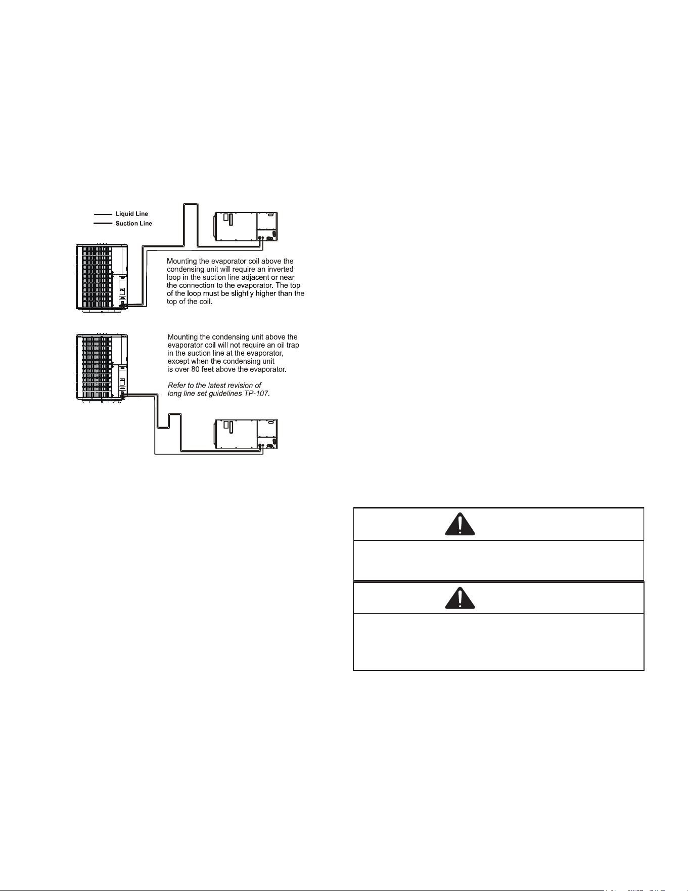
Do NOT let refrigerant lines come in direct contact with plumb-
ing, ductwork, oor joists, wall studs, oors, and walls. When
running refrigerant lines through a foundation or wall, openings
should allow for sound and vibration absorbing material to be
placed or installed between tubing and foundation. Any gap
between foundation or wall and refrigerant lines should be
lled with a pliable silicon-based caulk, RTV or a vibration
damping material. Avoid suspending refrigerant tubing from
joists and studs with rigid wire or straps that would come in
contact with the tubing. Use an insulated or suspension type
hanger. Keep both lines separate and always insulate the
suction line.
These sizes are suitable for line lengths of 79 feet or less.
If a run of more than eighty feet is required, refer to TP-107
Long Line Set Application R-410A or contact your distributor
for assistance.
Cond
Unit
Tons Suct Liq Suct Liq Suct Liq
1 1/2 5/8 1/4 3/4 3/8 3/4 3/8
2 5/8 1/4 3/4 3/8 3/4 3/8
2 1/2 5/8 1/4 3/4 3/8 7/8 3/8
3 3/4 3/8 7/8 3/8 1 1/8 3/8
3 1/2 7/8 3/8 1 1/8 3/8 1 1/8 3/8
4 7/8 3/8 1 1/8 3/8 1 1/8 3/8
5 7/8 3/8 1 1/8 3/8 1 1/8 3/8
Line Diameter (In. OD)
RECOMMENDED INTERCONNECTING TUBING (Ft)
0-24
25-49
50-79*
* Lines greater than 79 feet in length or vertical elevation changes
more than 50 feet refer to the TP-107 R-410A Long Line Set
Application Guidelines or contact your distributor for assistance.
Insulation is necessary to prevent condensation from forming
and dropping from the suction line. Armaex (or satisfactory
equivalent) with 3/8” min. wall thickness is recommended. In
severe conditions (hot, high humidity areas) 1/2” insulation
may be required. Insulation must be installed in a manner
which protects tubing from damage and contamination.
Existing Line Sets
Where possible, drain as much residual compressor oil from
existing systems, lines, and traps; pay close attention to low
areas where oil may collect. Use of an approved ushing agent
is recommended followed by a nitrogen purge to remove any
4
remaining ushing agent from the lines or indoor coil. Re-
placement of indoor coil is recommended.
NOTE: If using existing indoor coil and changing
refrigerant types, ensure the indoor coil and metering
device are compatible with the type of refrigerant being
used. If new indoor coil is required check spec sheet or
AHRI for approved coil. If system is being replaced due to
compressor electrical failure, assume acid is in system.
Refer to Service Procedure S-115 Compressor Burnout
in service manual for clean-up procedure.
Burying Refrigerant Lines
If burying refrigerant lines can not be avoided, use the fol-
lowing checklist.
1. Insulate liquid and suction lines separately.
2. Enclose all underground portions of the refrigerant
lines in waterproof material (conduit or pipe) sealing
the ends where tubing enters/exits the enclosure.
3. If the lines must pass under or through a concrete slab,
ensure lines are adequately protected and sealed.
Refrigerant Line Connections
IMPORTANT
To avoid overheating the service valve, TXV valve, or
lter drier while brazing, wrap the component with
a wet rag, or use a thermal heat trap compound.
Be sure to follow the manufacturer’s instruction
when using the heat trap compound. Note: Remove
Schrader valves from service valves before brazing
tubes to the valves. Use a brazing alloy of 2%
minimum silver content. Do not use ux.
Torch heat required to braze tubes of various sizes is
proportional to the size of the tube. Tubes of smaller
size require less heat to bring the tube to brazing
temperature before adding brazing alloy. Applying
too much heat to any tube can melt the tube. Service
personnel must use the appropriate heat level for the
size of the tube being brazed. NOTE: The use of a
heat shield when brazing is recommended to avoid
burning the serial plate or the nish on the unit.
1. The ends of the refrigerant lines must be cut square,
deburred, cleaned, and be round and free from nicks
or dents. Any other condition increases the chance of
a refrigerant leak.
2. “Sweep” the refrigerant line with nitrogen or inert gas
during brazing to prevent the formation of copper-
oxide inside the refrigerant lines. The POE oils used
in R-410A applications will clean any copper-oxide
present from the inside of the refrigerant lines and
spread it throughout the system. This may cause a
blockage or failure of the metering device.
3. After brazing, quench the joints with water or a wet
cloth to prevent overheating of the service valve.
4. Ensure the lter drier paint nish is intact after brazing.
If the paint of the steel lter drier has been burned or
chipped, repaint or treat with a rust preventative. This
is especially important on suction line lter driers which
are continually wet when the unit is operating.
NOTE: Be careful not to kink or dent refrigerant lines. Kinked
or dented lines will cause poor performance or compressor
damage.
Do NOT make nal refrigerant line connection until plugs
are removed from refrigerant tubing.
NOTE: Before brazing, verify indoor TXV is correct for R410A
and proper size.
Leak Testing (Nitrogen or Nirtogen-Traced)
WARNING
To avoid the risk of fire or explosion, never use
oxygen, high pressure air or flammable gases
for leak testing of a refrigeration system.
WARNING
To avoid possible explosion, the line from the
nitrogen cylinder must include a pressure
regulator and a pressure relief valve. The
pressure relief valve must be set to open at no
more than 450 psig.
Using dry nitrogen, pressurize the system to 450 PSIG. Allow
the pressure to stabilize and hold for 15 minutes (minimum).
If the pressure does not drop below 450 PSIG the system is
considered leak free. Proceed to system evacuation using
the Deep Vacuum Method. If after 15 minutes the pressure
drops below 450 PSIG follow the procedure outlined below
to identify system leaks. Repeat the Standing Pressure Test.
Leak Test the system using dry nirtogen and soapy water to
identify leaks. If you prefer to use an electronic leak detector,
charge the system to 10 PSIG with the appropriate system
refrigerant (see Serial Data Plate for refrigerant identication).
Do not use an alternative refrigerant. Using dry nitrogen nish
5
charging the system to 450 PSIG. Apply the leak detector to all
suspect areas. When leaks are discovered, repair the leaks,
and repeat the pressure test. If leaks have been eliminated
proceed to system evacuation.
System Evacuation
Condensing unit liquid and suction valves are closed to con-
tain the charge within the unit. The unit is shipped with the
valve stems closed and caps installed. Do not open valves
until the system is evacuated.
REFRIGERANT UNDER PRESSURE!
F
AILURE
TO
FOLLOW
PROPER
PROCEDURES
MAY
CAUSE
PROPERTY
DAMAGE
,
PERSONAL
INJURY
OR
DEATH
.
WARNING
NOTE: Scroll compressors should never be used to evacuate
or pump down a heat pump or air conditioning system.
P
ROLONGED
OPERATION
AT
SUCTION
PRESSURES
LESS
THAN
20
PSIG
FOR
MORE
THAN
5
SECONDS
WILL
RESULT
IN
OVERHEATING
OF
THE
SCROLLS
AND
PERMANENT
DAMAGE
TO
THE
SCROLL
TIPS
,
DRIVE
BEARINGS
AND
INTERNAL
SEAL
.
CAUTION
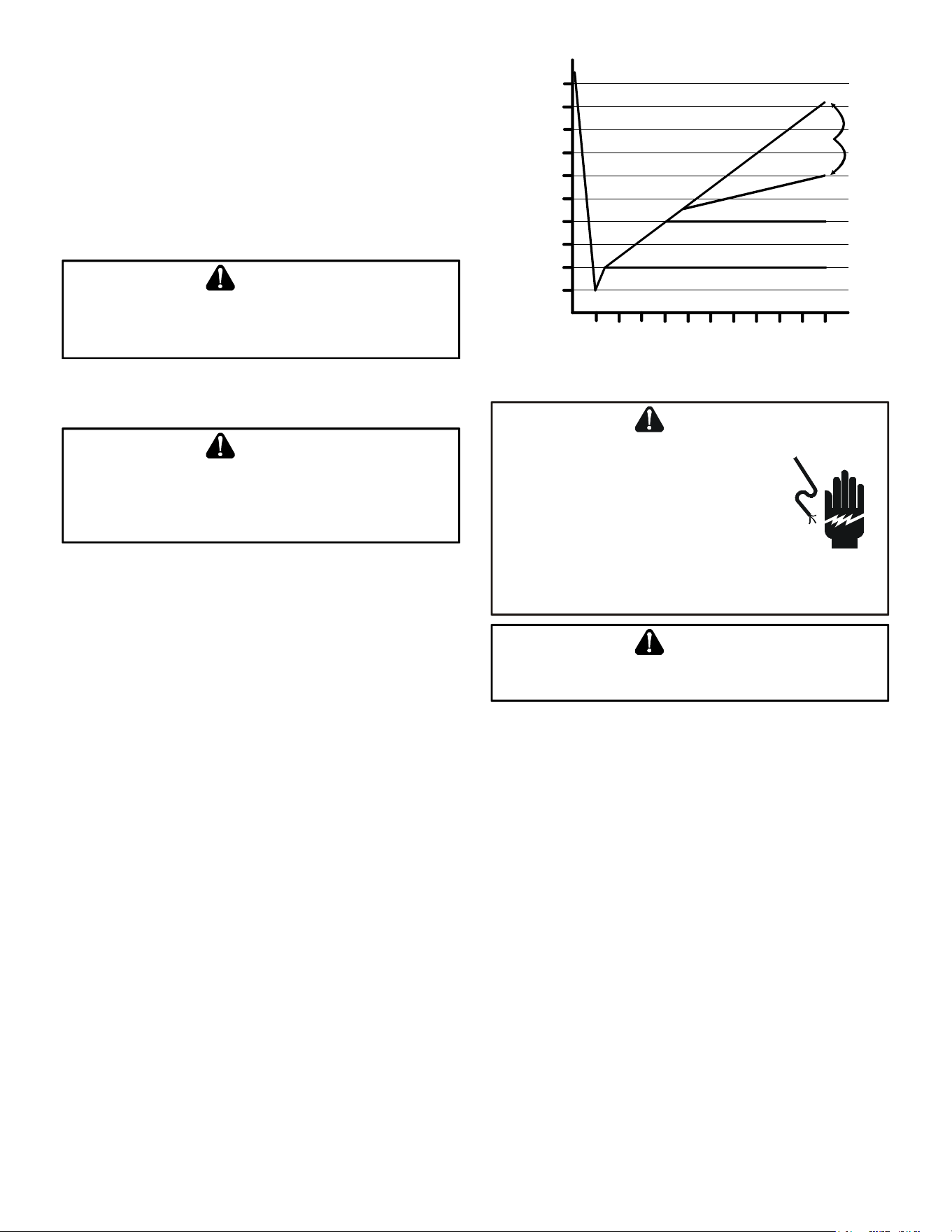
Deep Vacuum Method (Recommended)
The Deep Vacuum Method requires a vacuum pump
rated for 500 microns or less. This method is an eective
and ecient way of assuring the system is free of non-
condensable air and moisture. As an alternative, the Triple
Evacuation Method is detailed in the Service Manual for
this product model.
It is recommended to remove the Schrader Cores from the
service valves using a core-removal tool to expedite the
evacuation procedure.
1. Connect the vacuum pump, micron gauge, and vacuum
rated hoses to both service valves. Evacuation must
use both service valves to eliminate system mechanical
seals.
2. Evacuate the system to less than 500 microns.
3. Isolate the pump from the system and hold vacuum
for 10 minutes (minimum). Typically, pressure will rise
slowly during this period. If the pressure rises to less
than 1000 microns and remains steady, the system is
considered leak-free; proceed to system charging and
startup.
4. If pressure rises above 1000 microns but holds steady
below 2000 microns, non-condensable air or moisture
may remain or a small leak is present. Return to step
2: If the same result is achieved check for leaks and
repair. Repeat the evacuation procedure.
5. If pressure rises above 2000 microns, a leak is present.
Check for leaks and repair. Repeat the evacuation
procedure.
5000
4500
4000
3500
3000
2500
2000
1500
1000
500
0 1 2 3 4 5 6 7 8 9
10
LEAK(S)
PRESENT
MINUTES
V
ACUUM
IN
MICRONS
CONDENSIBLES OR SMALL
LEAK PRESENT
NO LEAKS
NO CONDENSIBLES
Electrical Connections
HIGH VOLTAGE!
D
ISCONNECT
ALL
POWER
BEFORE
SERVICING
.
M
ULTIPLE
POWER
SOURCES
MAY
BE
PRESENT
. F
AILURE
TO
DO
SO
MAY
CAUSE
PROPERTY
DAMAGE
,
PERSONAL
INJURY
OR
DEATH
DUE
TO
ELECTRIC
SHOCK
. W
IRING
MUST
CONFORM
WITH
NEC
OR
CEC
AND
ALL
LOCAL
CODES
. U
NDERSIZED
WIRES
COULD
CAUSE
POOR
EQUIPMENT
PERFORMANCE
,
EQUIPMENT
DAMAGE
OR
FIRE
.
WARNING
T
O
AVOID
THE
RISK
OF
FIRE
OR
EQUIPMENT
DAMAGE
,
USE
COPPER
CONDUCTORS
.
WARNING
The condensing unit rating plate lists pertinent electrical
data necessary for proper electrical service and overcurrent
protection. Wires should be sized to limit voltage drop to 2%
(max.) from the main breaker or fuse panel to the condensing
unit. Consult the NEC, CEC, and all local codes to determine
the correct wire gauge and length.
Local codes often require a disconnect switch located near
the unit; do not install the switch on the unit. Refer to the
installation instructions supplied with the indoor furnace/air
handler for specic wiring connections and indoor unit con-
guration. Likewise, consult the instructions packaged with
the thermostat for mounting and location information.
Overcurrent Protection
The following overcurrent protection devices are approved
for use.
• Time delay fuses
• HACR type circuit breakers
These devices have sucient time delay to permit the mo-
tor-compressor to start and accelerate its load.
6
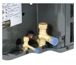
High Voltage Connections
Route power supply and ground wires through the high volt-
age port and terminate in accordance with the wiring diagram
provided inside the control panel cover.
Low Voltage Connections
This heat pump is equipped with a factory-installed transformer
to power the outdoor controls when installed as part of a fully
communicating HVAC system utilizing a ComfortBridge™
compatible indoor unit. In this conguration, only two low
voltage control wires are required between the outdoor unit
and indoor unit.
The unit also has legacy 24 VAC inputs and outputs to support
non-communicating systems. When this conguration is used,
the transformer in the outdoor unit must be disconnected from
the low voltage and line voltage connections. The transformer
connecting wires can then be discarded. Route control wires
through the low voltage port and terminate in accordance with
the wiring diagram provided inside the control panel cover.
HIGH
VOLTAGE
PORT
LOW
VOLTAGE
PORT
Voltage Ports
NOTE: For two-stage units, refer to the Installation Instructions
supplied with the variable speed indoor units for eld wiring
connections.
NOTE: If the heat pump unit is wired in the communicating
mode together with a compatible communicating indoor unit,
then the communicating equipment is able to search and
identify the condensing unit when power is applied to the
system. Refer to the Installation Manual of the communicating
indoor equipment for more information.
For non-communicating (legacy 24VAC) installations, use
the dipswitch to select defrost time interval (30, 60, 90, 120
minutes; see chart below).
Factory default setting is 30 minutes. The maximum defrost
cycle time is 10 minutes.
60
30
0
30 Minutes
60
60
30
0
60 Minutes
60
120 Minutes
60
30
0
90 Minutes
60
60
30
0
60
Dipswitch Settings for Selection of Defrost Time
System Start Up
POSSIBLE REFRIGERANT LEAK!
T
O
AVOID
A
POSSIBLE
REFRIGERANT
LEAK
,
OPEN
THE
SERVICE
VALVES
UNTIL
THE
TOP
OF
THE
STEM
IS
1/8”
FROM
THE
RETAINER
.
CAUTION
NOTE: Power must be supplied to the 18 SEER outdoor units
containing ECM motors before the power is applied to the
indoor unit. Sending a low voltage signal without high voltage
power present at the outdoor unit can cause malfunction of
the control module on the ECM motor.
Adequate refrigerant charge for the matching evaporator
coil or air handler and 15 feet of lineset is supplied with the
condensing unit. If using evaporator coils or air handlers
other than HSVTC coil it maybe necessary to add or remove
refrigerant to attain proper charge. If line set exceeds 15 feet
in length, refrigerant should be added at .6 ounces per foot
of liquid line.
NOTE: Charge should always be checked using superheat
when using a piston and subcooling when using TXV equipped
indoor coil to verify proper charge.
Break vacuum by fully opening liquid service valve. After the
refrigerant charge has bled into the system, open the suction
service valve. The service valve cap is the secondary seal for
the valves and must be properly tightened to prevent leaks.
Make sure cap is clean and apply refrigerant oil to threads and
sealing surface on inside of cap. Tighten cap nger-tight and
then tighten additional 1/6 of a turn (1 wrench at), or to the
following specication, to properly seat the sealing surfaces.
When opening valves with retainers, open each valve only
until the top of the stem is 1/8” from the retainer. To avoid loss
of refrigerant, DO NOT apply pressure to the retainer. When
opening valves without a retainer remove service valve cap
and insert a hex wrench into the valve stem and back out the
stem by turning the hex wrench counterclockwise. Open the
valve until it contacts the rolled lip of the valve body.
NOTE: These are not back-seating valves. It is not necessary
to force the stem tightly against the rolled lip.
After the refrigerant charge has bled into the system, open the
liquid service valve. The service valve cap is the secondary
seal for the valve and must be properly tightened to prevent
7
leaks. Make sure cap is clean and apply refrigerant oil to
threads and sealing surface on inside of cap. Tighten cap
nger-tight and then tighten additional 1/6 of a turn (1 wrench
at) to properly seat the sealing surfaces.
Do not introduce liquid refrigerant from the cylinder into
the crankcase of the compressor as this may damage
the compressor.
1. Break vacuum by fully opening liquid and suction base
valves.
2. Set thermostat to call for cooling. Check indoor and
outdoor fan operation and allow system to stabilize
for 10 minutes for xed orices and 20 minutes for
expansion valves.
Charge Verification
REFRIGERANT UNDER PRESSURE!
• D
O
NOT
OVERCHARGE
SYSTEM
WITH
REFRIGERANT
.
• D
O
NOT
OPERATE
UNIT
IN
A
VACUUM
OR
AT
NEGATIVE
PRESSURE
.
F
AILURE
TO
FOLLOW
PROPER
PROCEDURES
MAY
CAUSE
PROPERTY
DAMAGE
,
PERSONAL
INJURY
OR
DEATH
.
WARNING
U
SE
REFRIGERANT
CERTIFIED
TO
AHRI
STANDARDS
. U
SED
REFRIGERANT
MAY
CAUSE
COMPRESSOR
DAMAGE
,
AND
DAMAGE
CAUSED
BY
USED
REGRIGERANT
IS
NOT
COVERED
UNDER
THE
WARRANTY
. M
OST
PORTABLE
MACHINES
CANNOT
CLEAN
USED
REFRIGERANT
TO
MEET
AHRI
STANDARDS
.
CAUTION
V
IOLATION
OF
EPA
REGULATIONS
MAY
RESULT
IN
FINES
OR
OTHER
PENALTIES
.
NOTICE
CAUTION
Damage to the unit caused by operating the
compressor with the suction valve closed is not
covered under the warranty and may cause serious
compressor damage.
Final Charge Adjustment
Airow and Total Static Pressure for the indoor unit should
be veried before attempting to charge system.
1. Total static pressure is .5” WC or less.
2. Airow is correct for installed unit.
3. Airow tables are in the installation manual and Spec
Sheet for Indoor Unit.
4. Complete charging information are in Service Manual
RS6200006
NOTE: Superheat adjustments should not be made
until indoor ambient conditions have stabilized.
This could take up to 24 hours depending on
indoor temperature and humidity. Before checking
superheat run the unit in cooling for 10-15 minutes
or until refrigerant pressures stabilize. Use the
following guidelines and methods to check unit
operation and ensure that the refrigerant charge
is within limits.
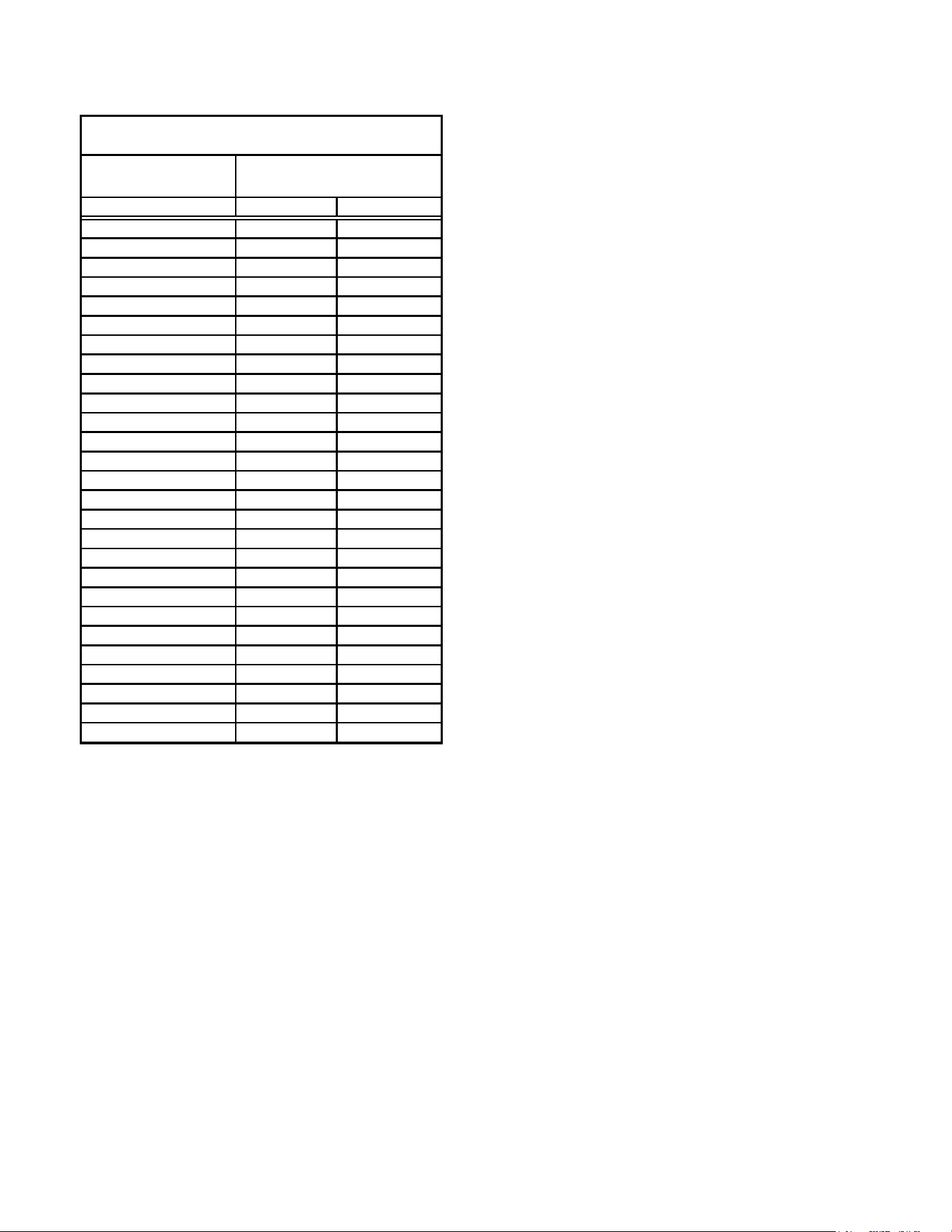
SUCTION PRESSURE
PSIG R-22 R-410A
50 26 1
52 28 3
54 29 4
56 31 6
58 32 7
60 34 8
62 35 10
64 37 11
66 38 13
68 40 14
70 41 15
72 42 16
74 44 17
76 45 19
78 46 20
80 48 21
85 50 24
90 53 26
95 56 29
100 59 31
110 64 36
120 69 41
130 73 45
140 78 49
150 83 53
160 86 56
170 90 60
SATURATED SUCTION PRESSURE
TEMPERATURE CHART
SATURATED SUCTION
TEMPERATURE ºF
Expansion Valve System
T
O
PREVENT
PERSONAL
INJURY
,
CAREFULLY
CONNECT
AND
DISCONNECT
MANIFOLD
GAUGE
HOSES
. E
SCAPING
LIQUID
REFRIGERANT
CAN
CAUSE
BURNS
. D
O
NOT
VENT
REFRIGERANT
INTO
THE
ATMOSPHERE
. R
ECOVER
ALL
REFRIGERANT
DURING
SYSTEM
REPAIR
AND
BEFORE
FINAL
UNIT
DISPOSAL
.
CAUTION
NOTE: Units matched with indoor coils equipped with
non-adjustable TXV should be charged by subcooling
only.
Run the unit on low stage cooling for 10 minutes until re-
frigerant pressures stabilize. Use the following guidelines
and methods to check unit operation and ensure that the
refrigerant charge is within limits. NOTE: Charge the unit
on low stage.
1. Purge the gauge lines and connect the service gauge
manifold to the base valve service ports.
2. Clamp a pipe clamp thermometer on the liquid line
near the liquid line service valve and 4-6” from the
compressor on the suction line.
a. Ensure the thermometer makes adequate contact
to obtain the best possible readings.
8
b. The temperature read with the thermometer should
be lower than the saturated condensing temperature.
LIQUID PRESSURE
PSIG
R-22
R-410A
200
101
70
210
105
73
220
108
76
225
110
78
235
113
80
245 116 83
255 119 85
265 121 88
275 124 90
285 127 92
295 130 95
305 133 97
325 137 101
355 144 108
375 148 112
405 155 118
415 157 119
425 n/a 121
435 n/a 123
445 n/a 125
475 n/a 130
500 n/a 134
525 n/a 138
550 n/a 142
575 n/a 145
600 n/a 149
625 n/a 152
SATURATED LIQUID PRESSURE
TEMPERATURE CHART
SATURATED LIQUID
TEMPERATURE ºF
3. The difference between the measured saturated
condensing temperature and the liquid line temperature
is the liquid Subcooling value.
4. TXV-based systems should have a Subcooling value
of 6°F +/- 1°F.
5. Add refrigerant to increase Subcooling and remove
refrigerant to decrease Subcooling.
NOTE: Units matched with indoor coils equipped with a
TXV should be charged by Subcooling only. Superheat
can also be utilized to best verify charge levels with an
adjustable TXV and make adjustments when needed
in unique applications due to refrigerant line length,
dierences in height between the indoor and outdoor unit
and refrigerant tubing sizes. These adjustments should
only be performed by qualied service personnel.
Advance Adjustment Recommendations
1. Clamp a pipe clamp thermometer near the suction line
service valve at the outdoor unit.
a. Ensure the thermometer makes adequate contact
for the best possible readings.
b. The temperature read with the thermometer should
be higher than the saturated suction temperature.
2. The dierence between the measured saturated suction
temperature and the suction line temperature is the
Superheat value.
3. TXV-based systems should have a Superheat value of
8°F +/- 1°F.
4. Adjust Superheat by turning the TXV valve stem
clockwise to increase and counterclockwise to
decrease.
a. If Subcooling and Superheat are low, adjust the
TXV to 8°F +/- 1°F, and then check Subcooling.
b. If Subcooling is low and Superheat is high, add
charge to raise Subcooling to 6°F +/- 1°F then
check Superheat.
c. If Subcooling and Superheat are high, adjust the
TXV valve to 8°F +/- 1°F Superheat, then check
the Subcooling value.
d. If Subcooling is high and Superheat is low, adjust
the TXV valve to 8°F +/- 1°F Superheat and remove
charge to lower the Subcooling to 6°F +/- 1°F.
NOTE: DO NOT adjust the charge based exclusively on
suction pressure unless for general charging in the case of
a gross undercharge.
NOTE: Check the Schrader ports for leaks and tighten valve
cores if necessary. Install caps nger-tight.
Heat Pump - Heating Cycle
The proper method of charging a heat pump in the heat mode
is by weight with the additional charge adjustments for line
size, line length, and other system components. To achieve
maximum performance, adjust the OD TXV to 4°F +/- 1°F su-
perheat and subcool below 40° F at 4-6” from the compressor.
Make nal charge adjustments in the cooling cycle.
Low Speed Lock-Out: The outdoor system has a low speed
lock-out feature. In communicating mode, below 37°F outdoor
ambient, the system locks out low stage and operates only in
high stage to provide maximum heating capacity.
Additional Notes
1. There are (3) 7-segment LED displays on the PCB.
Refer to the Troubleshooting chart at the end of this
manual for denitions of the LED status.
2. “TERM” dip switch is used for communications bus
conguration. Leave the settings to the factory default
position.
9
3. “LEARN” push button is used to reset the communications
between the equipment. Used only for troubleshooting
purposes.
4. Press “TEST” push button, during system “Standby”
mode to turn on both the compressor and outdoor fan
for ve seconds.
5. The “RECALL” push button is used to retrieve the six
most recent faults. The control must be in Standby Mode
(no thermostat inputs) to use the feature. Depress the
push button for approximately two seconds and less
than ve seconds. The 7-segment LED displays will
then display the six most recent faults beginning with
the most recent fault and decrementing to the least
recent fault. The faults may be cleared by depressing
the button for greater than ve seconds. Consecutively
repeated faults are displayed a maximum of three
times. Refer to the fault code denitions at the end of
this manual for more details.
6. A forced defrost can be initiated by pressing “TEST” and
“RECALL” push buttons simultaneously for more than
1 second with a valid call for heat. The forced defrost
can be terminated by
• A 10 minute lapse in time,
• A coil temperature rise above 75°F or
• By pressing the two buttons again for more than 1
second.
ComfortBridge™ System
Overview
The ComfortBridge based two stage heating and air condi-
tioning system uses an indoor unit and outdoor unit digitally
communicating with one another via a two-way communica-
tions path.
In a traditional system, the thermostat sends commands to
the indoor and outdoor units via analog 24 VAC signals. It is
a one-way communication path in that the indoor and outdoor
units typically do not return information to the thermostat.
The indoor unit, and outdoor unit, comprising of a
ComfortBridge system “communicate” digitally with one
another creating a two-way communications path. The
thermostat still sends commands to the indoor unit, however,
the 24VAC indoor and outdoor unit may also request and
receive information from one another to optimize system
performance.
Two-way digital communications is accomplished using only
two wires between the indoor and outdoor units. The heat
pump control board is powered by 24 VAC, which is supplied
by the factory-installed transformer in the heat pump control
box.
Airflow Consideration
Airow demands are managed dierently in a fully commu-
nicating system than they are in a legacy wired system. The
system operating mode (as determined by the thermostat)
determines which unit calculates the system airow demand.
If the indoor unit is responsible for determining the airow
demand, it calculates the demand and sends it to the ECM
motor. If the outdoor unit or thermostat is responsible for
determining the demand, it calculates the demand and trans-
mits the demand along with a fan request to the indoor unit.
The indoor unit then sends the demand to the ECM motor.
The table below lists the various ComfortBridge compatible
systems, the operating mode, and airow demand source.
System
System Operating
Mode
Airflow
Demand Source
Cooling
Heat Pump
Heat Pump Heating
Only
Heat Pump
HP + Electric Heat
Strips
> of Heat Pump or Air
Handler Demand
Electric Heat Strips
Only
Air Handler
Continuous Fan
Thermostat
Cooling
Heat Pump
Heat Pump Heating
Only
Heat Pump
Auxiliary Heating
Furnace
Continuous Fan
Thermostat
Heat Pump + Air
Handler
Heat Pump +
Furnace
For example, assume the system is a heat pump matched
with an air handler. With a call for low stage cooling, the heat
pump will calculate the system’s low stage cooling airow
demand. The heat pump will then send a fan request along
with the low stage cooling airow demand to the air handler.
Once received, the air handler will send the low stage cooling
airow demand to the ECM motor. The ECM motor then de-
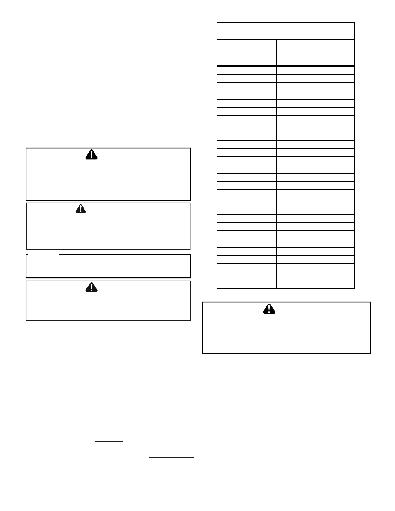
livers the low stage cooling airow. The following table lists
the nominal high and low stage airow for the ComfortBridge
heat pumps.
High Low High Low
*SZC160241
800 600 800 600
*SZC160361 1200 800
1200 800
*SZC160481
1550 1100 1550
1100
*SZC160601 1800 1210 1800 1210
*SZC180241
850 550 850
550
*SZC180361 1250 850 1250
850
*SZC180481 1550
1210 1550 1210
*SZC180601 1750 1210 1750 1210
*SZC702410 800 600 800 600
*SZC703610 1250 850 1250 850
*SZC704810 1550 1210 1550 1210
*SZC706010 1750 1210 1750 1210
Models
Cooling
Heating
10
Control Wiring
NOTE: Refer to section Electrical Connections - High Voltage
Connections for 208/230 volt line connections to the air
conditioner or heat pump.
NOTE: A removable plug connector is provided with the
control board to make thermostat wire connections. This
plug may be removed, wire connections made to the plug,
and replaced. It is strongly recommended that you do not
connect multiple wires into a single terminal. Wire nuts are
recommended to ensure one wire is used for each terminal.
Failure to do so may result in intermittent operation.
Typical 18 AWG thermostat wire may be used to wire the
system components. However, communications reliability
may be improved by using a high quality, shielded, twisted
pair cable for the data transmission lines. In either case, 150
feet is the maximum length of wire between indoor unit and
outdoor unit, or between indoor unit and thermostat.
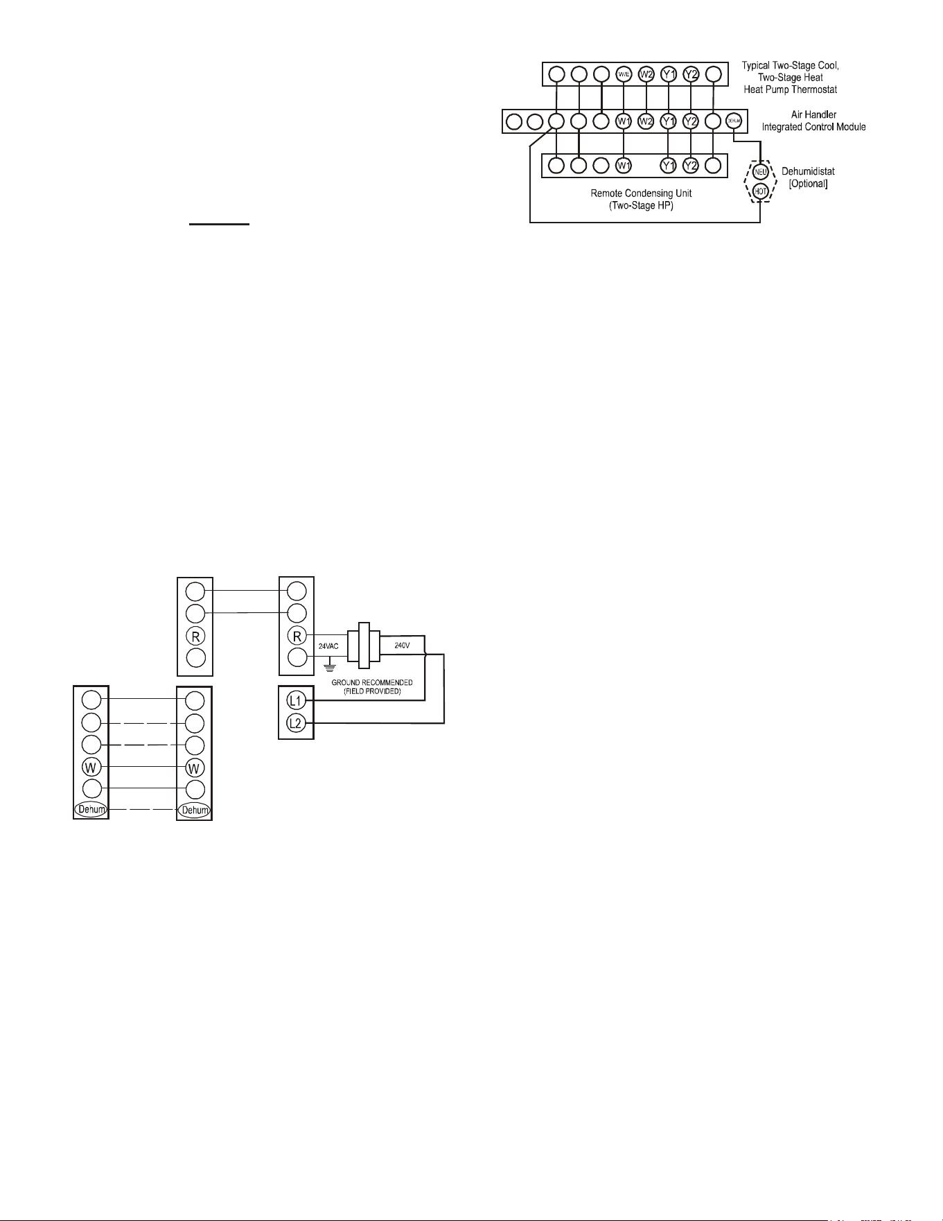
Two-Wire Outdoor
For communicating systems, only two wires are required
between the indoor and outdoor units. This wiring scheme
requires only the data lines, 1 and 2 between indoor and
outdoor equipment.
R
C
G
Y
Optional
Optional
Optional if
feature
supported by
thermostat
INDOOR
BOARD TERMINAL
CONNECTIONS
OUTDOOR
BOARD TERMINAL
CONNECTIONS
OUTDOOR
TRANSFORMER
1
2
C
R
C
G
Y
1
2
C
System Wiring using Two-Wires
between indoor and outdoor equipment
Legacy Controls Wiring
The integrated control board on this unit is factory-equipped
with a 4-pin connector for low voltage controls wiring for com-
municating systems. If the system is installed as a non-com-
municating (legacy) system, remove the 4-pin connector and
disconnect the transformer low voltage and line voltage wiring.
Then, install the 7-pin connector that is supplied in the litera-
ture/accessories bag into the integrated control board in the
appropriate location indicated by the color-coded labels found
on both the control board and pin connector plug.
R C G
O
R C G
O
R C G
O
1 2
System Wiring for legacy controls
ComfortBridge™ System Advanced Features
The ComfortBridge system permits access to additional
system information, advanced set-up features, and advanced
diagnostic/troubleshooting features via the control board push
buttons or the CoolCloud mobile app.
Fault Code History
Accessing the air conditioner/heat pump’s diagnostics menu
provides ready access to the last six faults detected by the
air conditioner/heat pump. Faults are stored most recent to
least recent. Any consecutively repeated fault is stored a
maximum of three times. Example: The power supply to the
air conditioner/heat pump is continuously below 187 VAC.
The control will only store this fault the rst three consecutive
times the fault occurs.
NOTE: It is highly recommended that the fault history be
cleared after performing maintenance or servicing the heat
pump.
Identification
Model Number, Serial Number and Software Version are
displayed within this menu. A model number check will help
determine if the equipment shared data is correct for the
unit. If the model number is not correct or no serial number
is visible, even though very rare, memory cards are available
to load the proper data.
Sensor Data
The outdoor ambient temperature and coil temperature are
displayed in the Sensor Data Menu. This information can be
used for troubleshooting purposes.
Device Settings
This menu allows for the adjustment of several cooling perfor-
mance variables. Cool Airow Trim (range from -10% to 10%
in 2% increments), Cool Airow Proles, Cool Fan ON Delay,
Cool Fan OFF Delay and Dehumidication Select (enable or
disable dehumidication) can be adjusted in this menu. See
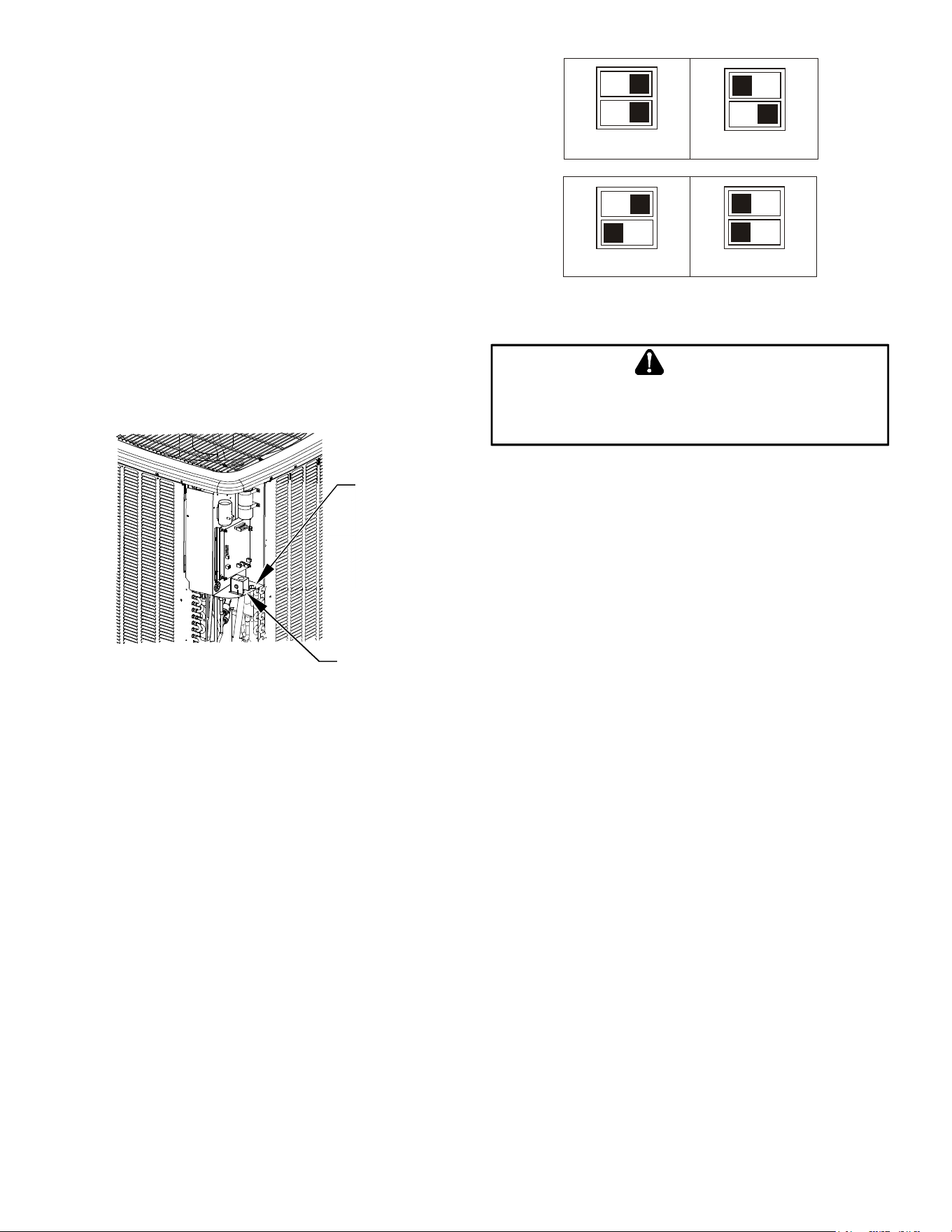
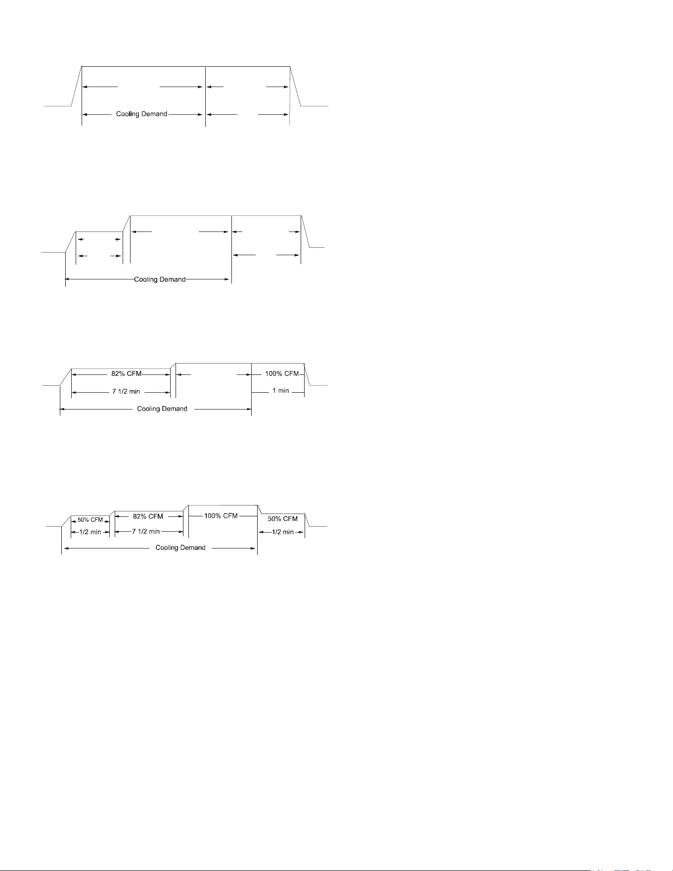
the following images showing the four cooling airow proles.
11
• Prole A (default) provides only an OFF delay of one
(1) minute at 100% of the cooling demand airow.
OFF
100% CFM 100% CFM
1 min
OFF
• Prole B ramps up to full cooling demand airow
by rst stepping up to 50% of the full demand for
30 seconds. The motor then ramps to 100% of the
required airow. A one (1) minute OFF delay at 100%
of the cooling airow.
50% CFM
1/2 min
100% CFM
100% CFM
1 min
OFF
OFF
• Prole C ramps up to 82% of the full cooling demand
airow and operates there for approximately 7 1/2
minutes. The motor then steps up to the full demand
airow. Prole C also has a one (1) minute 100% OFF
delay.
100% CFM
OFF
OFF
• Prole D ramps up to 50% of the demand for 1/2
minute, then ramps to 82% of the full cooling demand
airow and operates there for approximately 7 1/2
minutes. The motor then steps up to the full demand
airow. Prole D has a 1/2 minute at 50% airow
OFF delay.
OFF
OFF
Airow Tables
Heat Set-Up
This menu allows for the adjustment of several heating perfor-
mance variables. Heat Airow Trim (range from -10% to 10%
in 2% increments), Heat Fan ON Delay, Heat Fan OFF Delay,
Defrost Interval and Compressor Delay can be adjusted in this
menu. Defrost Interval determines the amount of compressor
run time between defrost cycles. Compressor delay selects a
compressor o time after a reversing valve shift.
Device Status
The current system operational mode and requested indoor
CFM is reported in this menu. This information can be used
for troubleshooting purposes.
Thermostat Menu
If this heat pump is installed with a ComfortBridge compatible
furnace, the system is recognized as a dual fuel system. The
balance point temperature should be set via the indoor unit.
See indoor unit instruction manual for details on how to set
the balance point.
System Troubleshooting
NOTE: Refer to the instructions accompanying the CT
compatible indoor air handler/furnace/modular blower unit for
troubleshooting information regarding indoor unit diagnostics..
Refer to the Troubleshooting Chart at the end of this manual
for a listing of possible air conditioner and heat pump error
codes, possible causes and corrective actions.
12
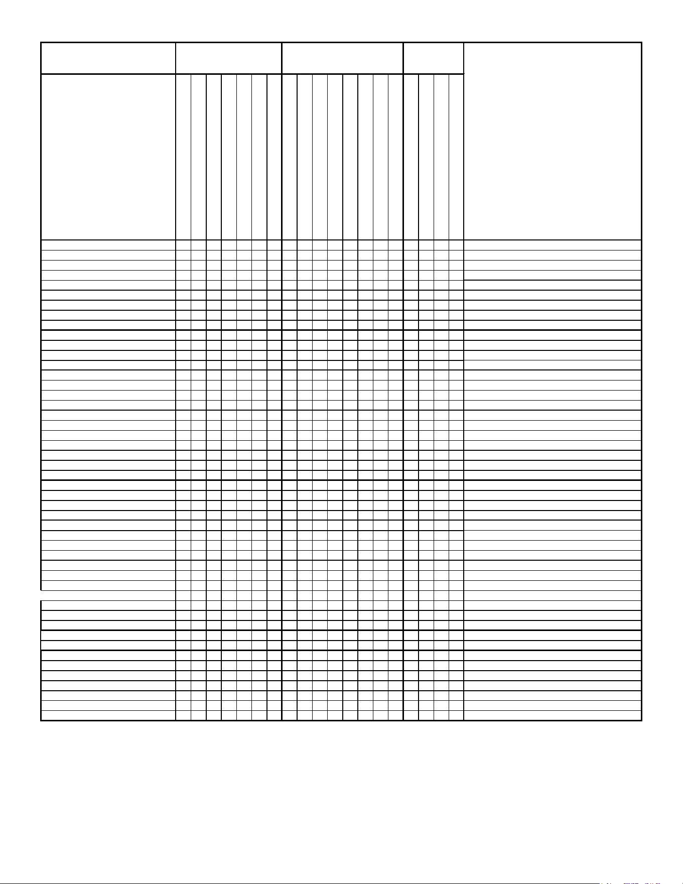
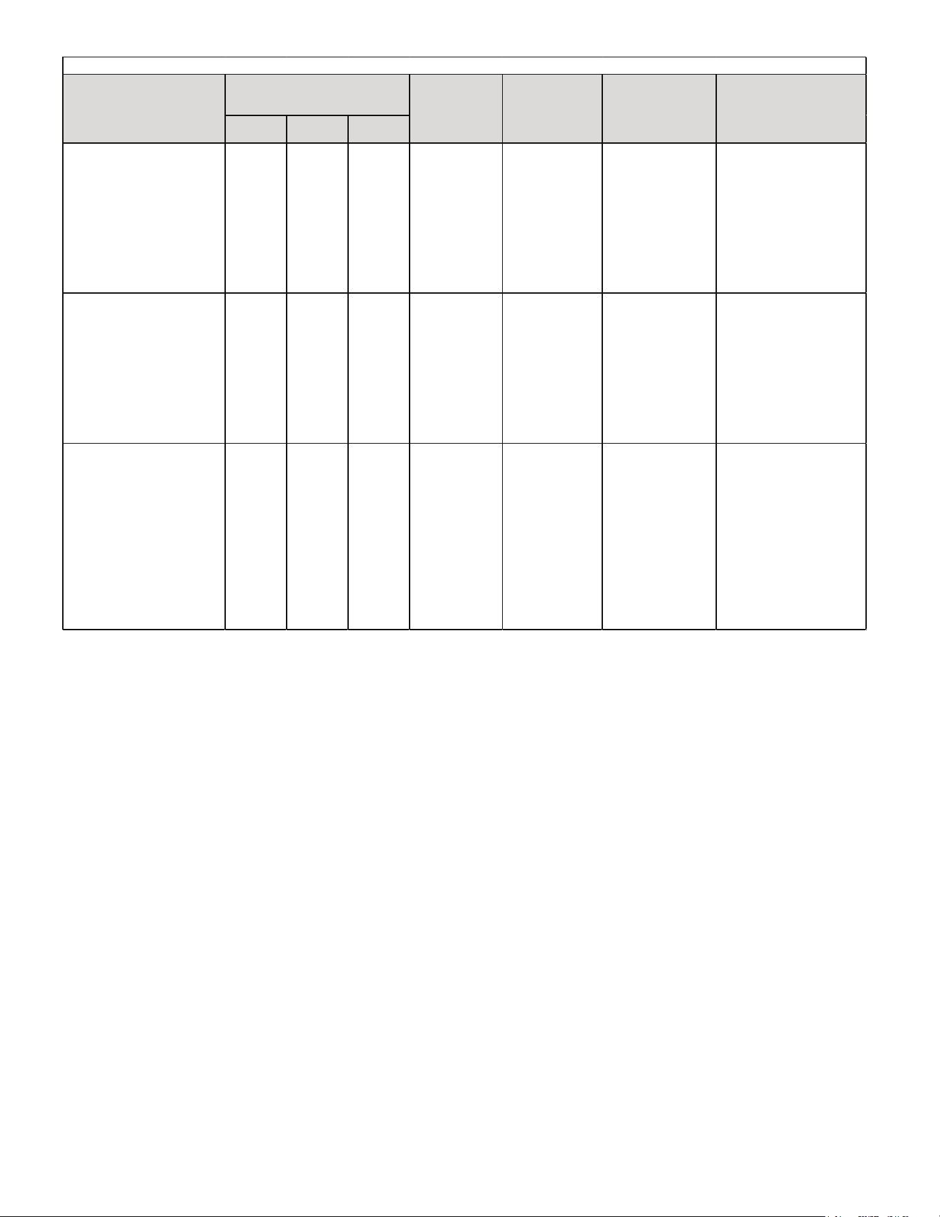
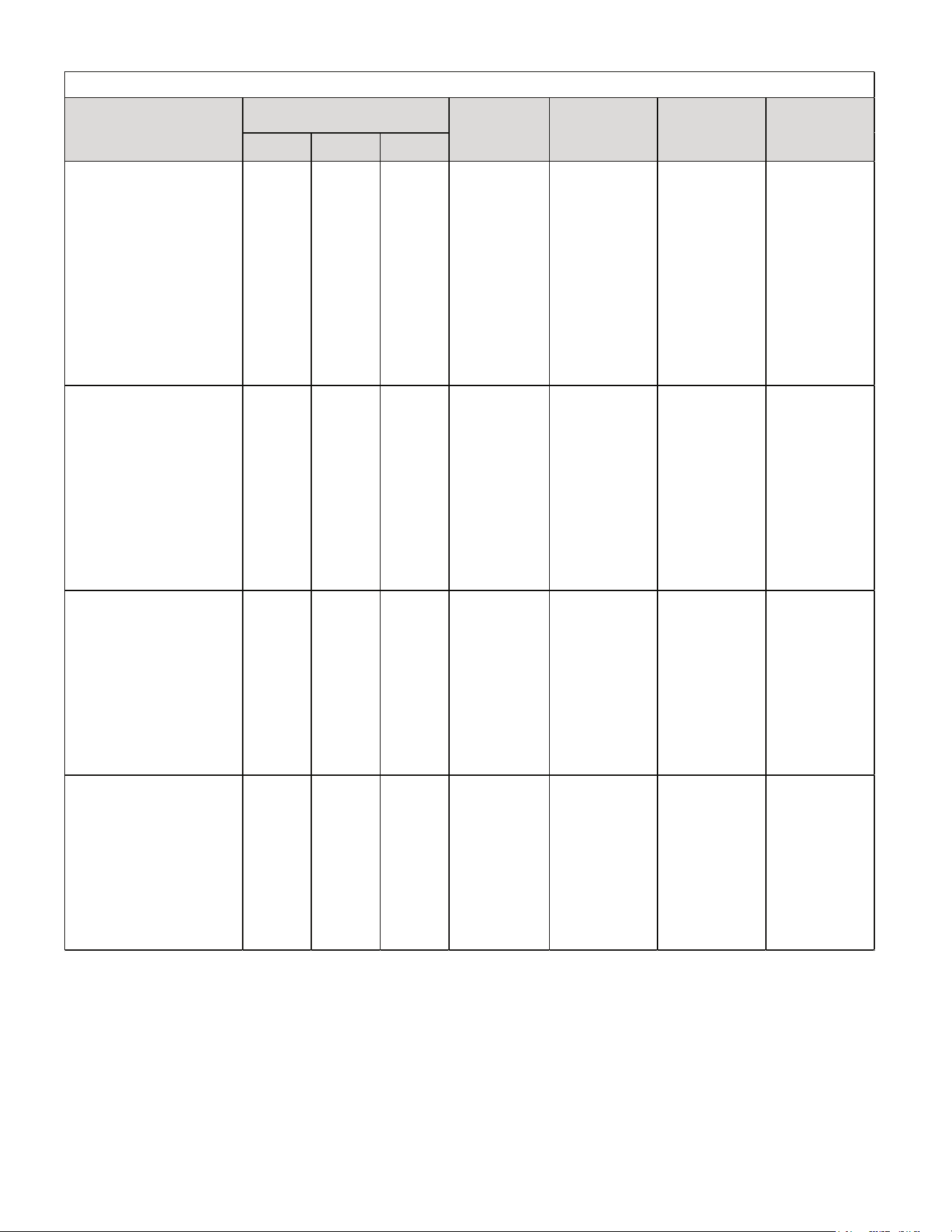
TROUBLESHOOTING INFORMATION: CONDENSING UNIT
For detailed service information refer to the Remote Condensing Unit Service manual.
Complaint
System
Operating
Pressures
POSSIBLE CAUSE
DOTS IN ANALYSIS
GUIDE INDICATE
"POSSIBLE CAUSE"
SYMPTOM
System will not start
Compressor will not start - fan runs
Comp. and Cond. Fan will not start
Evaporator fan will not start
Condenser fan will not start
Compressor runs - goes off on overload
Compressor cycles on overload
System runs continuously - little cooling/htg
Too cool and then too warm
Not cool enough on warm days
Certain areas too cool, others too warm
Compressor is noisy
System runs - blows cold air in heating
Unit will not terminate defrost
Unit will not defrost
Low suction pressure
Low head pressure
High suction pressure
High head pressure
Test Method
Remedy
Power Failure
•
Test Voltage
Blown Fuse
• • •
Inspect Fuse Size & Type
Unbalanced Power, 3PH
• • •
Test Voltage
Loose Connection
•
•
•
Inspect Connection - Tighten
Shorted or Broken Wires
•
•
•
•
• •
Test Circuits With Ohmmeter
Open Fan Overload
•
•
Test Continuity of Overload
Faulty Thermostat
• •
• •
Test Continuity of Thermostat & Wiring
Faulty Transformer
• •
Check Control Circuit with Voltmeter
Shorted or Open Capacitor
• • • • •
Test Capacitor
Internal
Compressor Overload Open
•
♦
Test Continuity of Overload
Shorted or Grounded Compressor
• •
Test Motor Windings
Compressor Stuck
• • •
♦
Use Test Cord
Faulty Compressor Contactor
• •
•
Test Continuity of Coil & Contacts
Faulty Fan Relay
•
Test Continuity of Coil And Contacts
Open Control Circuit
•
Test Control Circuit with Voltmeter
Low Voltage
• • •
Test Voltage
Faulty Evap. Fan Motor
• •
♦
Repair or Replace
Shorted or Grounded Fan Motor
• •
Test Motor Windings
Improper Cooling Anticipator
• •
Check Resistance of Anticipator
Shortage of Refrigerant
•
•
♦
•
•
Test For Leaks, Add Refrigerant
Restricted Liquid Line
•
• •
•
•
Remove Restriction, Replace Restricted Part
Open Element or Limit on Elec. Heater
♦ ♦
Test Heater Element and Controls
Dirty Air Filter
• • • •
♦
Inspect Filter-Clean or Replace
Dirty Indoor Coil
•
• •
•
♦
Inspect Coil - Clean
Not enough air across Indoor Coil
•
• •
•
♦
Check Blower Speed, Duct Static Press, Filter
Too much air across Indoor Coil
♦
•
Reduce Blower Speed
Overcharge of Refrigerant
•
•
•
♦
• •
Recover Part of Charge
Dirty Outdoor Coil
• •
•
♦
•
Inspect Coil - Clean
Noncondensibles
•
•
♦
•
Recover Charge, Evacuate, Recharge
Recirculation of Condensing Air
• • •
Remove Obstruction to Air Flow
Infiltration of Outdoor Air
• •
•
Check Windows, Doors, Vent Fans, Etc.
Improperly Located Thermostat
• •
Relocate Thermostat
Air Flow Unbalanced
• •
Readjust Air Volume Dampers
System Undersized
• •
Refigure Cooling Load
Broken Internal Parts
•
♦
Replace Compressor
Broken Valves
•
• •
•
Test Compressor Efficiency
Inefficient Compressor
•
♦
•
•
Test Compressor Efficiency
Wrong Type Expansion Valve
• • •
• • •
♦
Replace Valve
Expansion Device Restricted
• •
• • • • •
Remove Restriction or Replace Expansion Device
Oversized Expansion Valve
• •
Replace Valve
Undersized Expansion Valve
•
• • • •
Replace Valve
Expansion Valve Bulb Loose
•
•
Tighten Bulb Bracket
Inoperative Expansion Valve
• • •
Check Valve Operation
Loose Hold-down Bolts
•
Tighten Bolts
Faulty Reversing Valve
•
♦ ♦ ♦ ♦ ♦
♦
Replace Valve or Solenoid
Faulty Defrost Control
•
♦ ♦ ♦ ♦ ♦
♦
Test Control
Faulty Defrost Thermostat
♦ ♦ ♦
♦ ♦ ♦ ♦
Test Defrost Thermostat
Flowrator Not Seating Properly
• •
•
Check Flowrator & Seat or Replace Flowrator
• Cooling or Heating Cycle (Heat Pump)
♦
No Cooling
Unsatisfactory Cooling/Heating
Heating Cycle Only (Heat Pump)
13
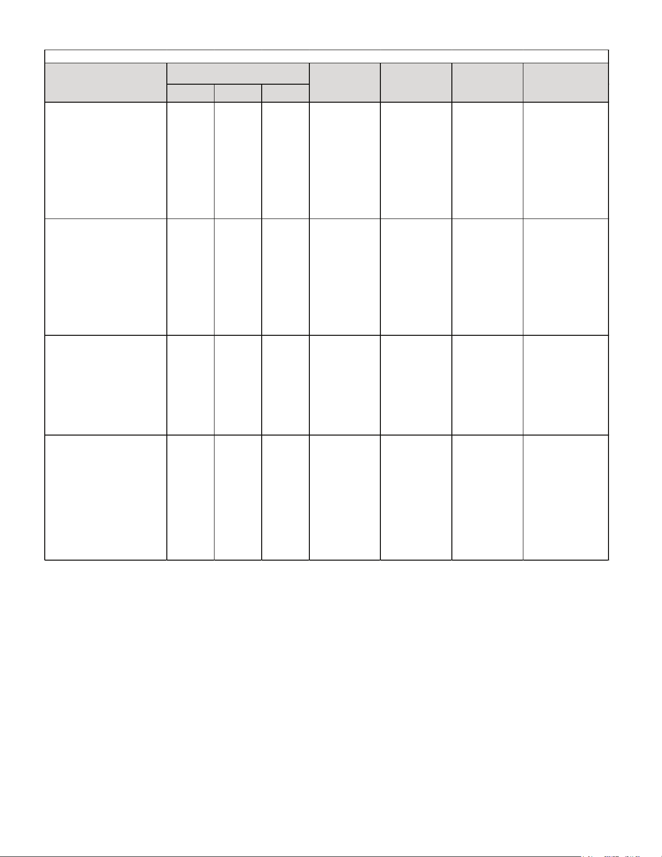
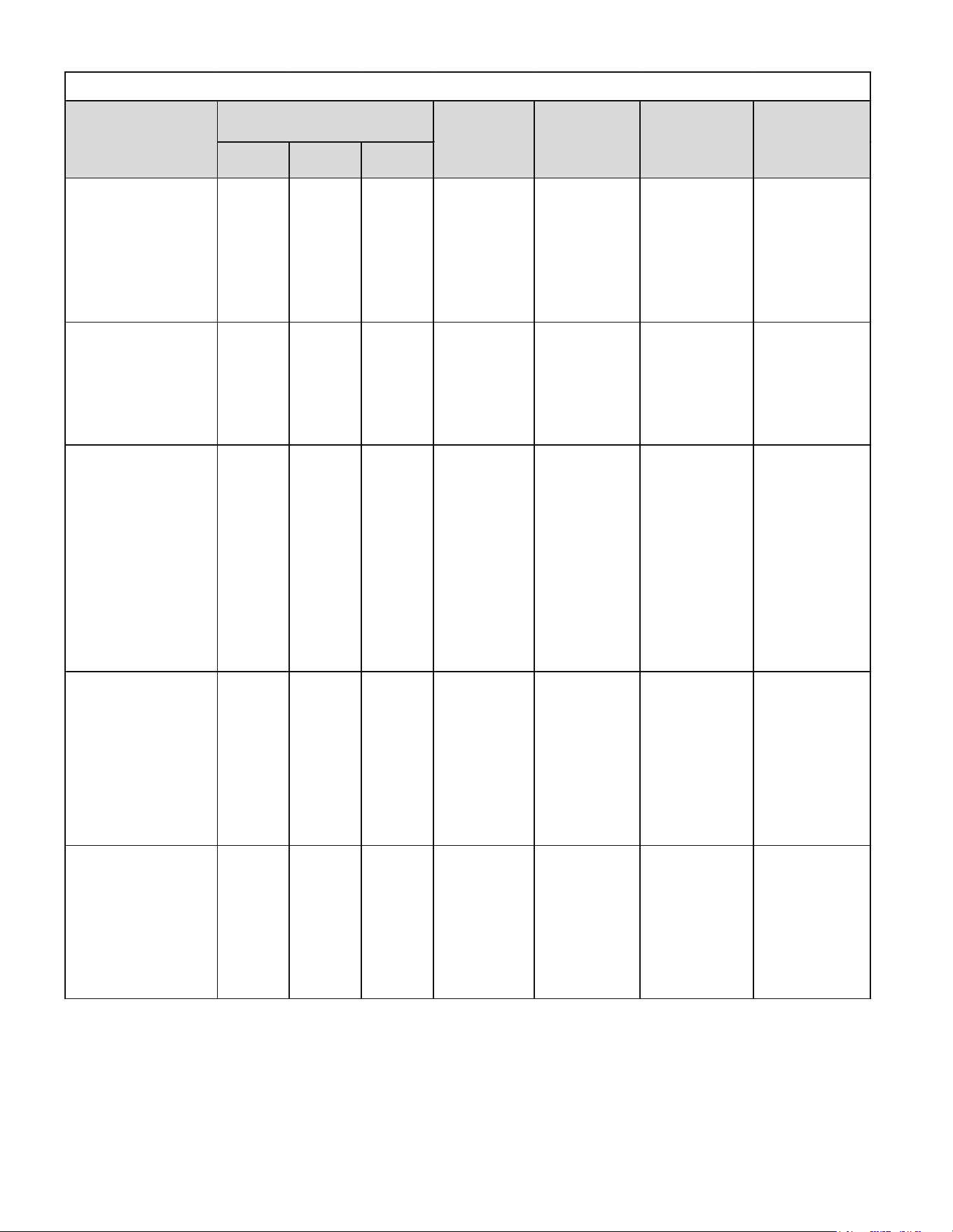
TROUBLESHOOTING INFORMATION: UNITARY DIAGNOSTIC CODES
Digit3 Digit2 Digit 1
• Integrated control module
diagnostic/status LED display shows
the indicated code.
BLANK A 2
• Outdoor air temp
sensor fault
• Shorted sensor.
• Open sensor.
• Sensor disconnected.
• Sensor out of range.
• Check sensor
connection.
• Replace open/ shorted
sensor.
• Turn power OFF prior to repair.
• Replace with correct
replacement part.
• Heat pump fails to operate in
heating mode.
• Integrated control module
diagnostic/status LED display shows
the indicated code.
BLANK A 3
• Outdoor coil temp
sensor fault
• Shorted sensor
• Open sensor.
• Sensor. disconnected.
• Sensor out of range.
• Check sensor
connection.
• Replace open/ shorted
sensor.
• Turn power OFF prior to repair.
• Replace with correct
replacement part.
• Air conditioner/heat pump fails to
operate.
• Integrated control module
diagnostic/status LED display shows
the
indicated code.
BLANK E 5 • Open fuse
• Short in low voltage
wiring.
• Locate and correct short
in low voltage wiring.
• Turn power OFF prior to repair.
• Replace fuse with
3-amp automotive type.
• Air conditioner/heat pump fails to
operate.
• Integrated control module
diagnostic/status LED display shows
the
indicated code.
BLANK E E • Board mis- operation
• Compressor relay
contacts welded.
• Replace control.
• Turn power OFF prior to repair
• Replace with correct
replacement part.
• Air conditioner/heat pump fails to
operate.
• Integrated control module
diagnostic/status LED display shows
the indicated code.
BLANK b 0
• Circulator
blower motor is not
running when it
should be running.
• Indoor bIower motor
problem.
• Communications error
between indoor and
outdoor unit.
• Check indoor bIower
motor.
• Check indoor bIower
motor wiring.
• Check indoor unit
control.
• Repair/ replace any
faulty wiring.
• Repair/ replace
indoor bIower motor or
control.
• Turn power OFF prior to repair.
• Replace with correct
replacement part.
• Air conditioner/heat
pump operates at reduced
performance.
• Air conditioner/heat pump
operating at low stage when expected
to operate at high stage.
• Integrated control module
diagnostic/status LED display shows
the indicated code.
BLANK b 9
• Air flow is lower
than demanded
• Indoor bIower motor
problem
• Blocked filters .
• Restrictive/ undersized
ductwork
• Indoor/ outdoor unit
miss-match.
• Check indoor blower
motor.
• Check Filters
clean/replace as needed.
• Check ductwork, resize
as needed.
• Verify indoor and
outdoor units are
properly matched.
• Turn power OFF prior to repair.
• Replace with correct
replacement part. See
specification sheets for airflow
requirements and maximum
external static pressure.
• See specification sheets for
approved system matches.
SYSTEM TROUBLESHOOTING
UNITARY DIAGNOSTIC CODES
Symptoms of Abnormal
Operation
Diagnostic/Status LE D
Display Codes
Fault Description Possible Causes
Corrective
Actions
Notes &
Cautions
14
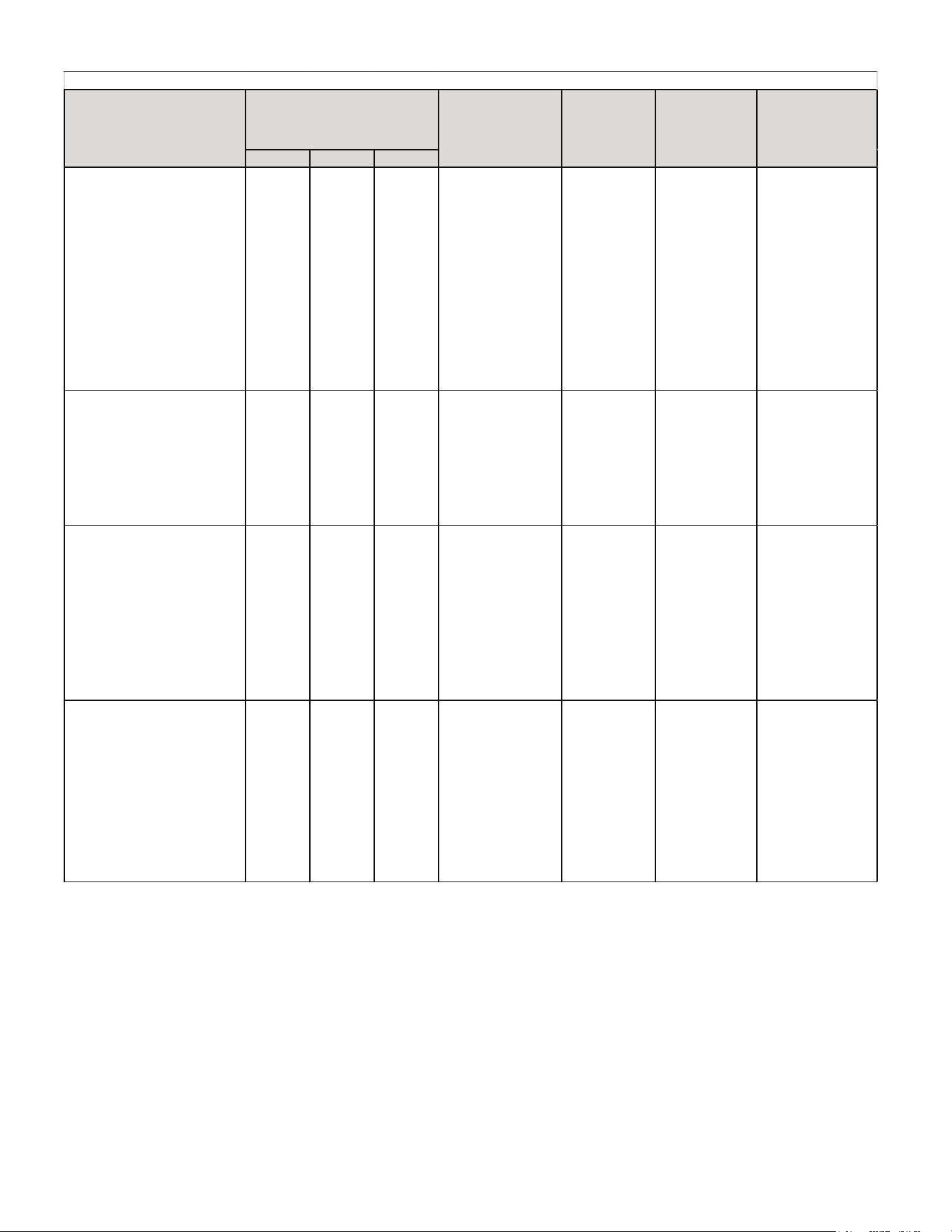
TROUBLESHOOTING INFORMATION: UNITARY DIAGNOSTIC CODES
• Air conditioner/heat pump fails to
operate.
• Integrated control module
diagnostic/status LED display shows
the indicated code.
BLANK d 0
• Data not yet on
Network
• Air conditioner/ heat
pump is wired as part of
a communicating
system and
integrated control
module does
not contain any shared
data.
• Verify system type
(communicating or legacy)
• Populate shared data
using memory card
• Wire system as legacy
system
• Turn power OFF prior to repair.
• Use memory card for your specific
model.
• Insert memory card BEFORE
turning power ON. Memory card
may be removed after data is loaded.
Turn power OFF before removing
memory card.
• Error code will be cleared once
data is loaded.
• Air conditioner/heat pump fails to
operate.
• Integrated control module
diagnostic/status LED display shows
the indicated code.
BLANK d 1
• Invalid Data on
Network
• Air conditioner/ heat
pump is wired as part of
a communicating
system and integrated
control module contains
invalid shared data or
network data is invalid
for
the integrated control
module.
• Verify system type
(communicating or legacy).
• Populate correct shared
data using memory card.
• Wire system as legacy
system.
• Turn power OFF prior to repair.
• Use memory card for your specific
model.
• Insert memory card BEFORE
turning power ON. Memory card
may be removed after data is loaded.
Turn power OFF before removing
memory card.
• Error code will be cleared once
data is loaded.
• Air conditioner/heat pump fails to
operate.
• Air conditioner/heat pump operating
at reduced performance.
• Air conditioner/heat pump operating
at low stage when e peeled to operate at
high stage.
• Integrated control module
diagnostic/status LED display shows
the indicated code.
BLANK d 2 • System
Mis-Match
• Air conditioner/ heat
pump is wired as part of
a communicating
system and outdoor unit
requires air flow greater
than indoor units
airflow capability.
• Shared data is
incompatible with the
system or missing
parameters.
• Verify system type
(communicating or legacy).
• Verify shared data is
correct for your specific
model repopulate data if
required.
• Wire system as legacy
system.
• Turn power OFF prior to repair.
• Use memory card for your specific
model.
• Insert memory card BEFORE
turning power ON. Memory card
may be removed after data is loaded.
Turn power OFF before removing
memory card.
• Error code will be cleared once
data is loaded.
Digit2 Digit 1
UNITARY DIAGNOSTIC CODES
Symptoms of
Abnormal Operation
Diagnostic/Status
LED Display Codes
Fault Description Possible Causes Corrective Actions Notes & Cautions
Digit3
15
TROUBLESHOOTING INFORMATION: UNITARY DIAGNOSTIC CODES
Digit 3 Digit 2 Digit 1
• Air conditioner/heat pump fails to
operate.
• Integrated control module
diagnostic/status LED display shows
the indicated code.
BLANK d 3
• Configuration Mis-
match
• Shared data sent to
integrated control
module does not
match hardware
configuration.
• Verify system type
(communicating or
legacy).
• Verify shared data
is correct for your
specific model; re-
populate data if
required.
• Wire system as
legacy system.
• Turn power OFF prior to
repair.
• Use memory card for
your specific model.
• Insert memory card
BEFORE turning power
ON. Memory card may be
removed after data is
loaded. Turn power OFF
before removing memory
card.
• Error code will be
cleared once data is
loaded.
• Air conditioner/heat pump fails to
operate.
• Integrated control module
diagnostic/status LED display shows
the indicated code.
BLANK d 4
• Invalid Memory
Card Data
• Shared data on
memory card has
been rejected.
• Verify system type
(communicating or
legacy).
• Verify shared data
is correct for your
specific model; re-
populate data if
required.
• Wire system as
legacy system.
• Turn power OFF prior to
repair.
• Use memory card for
your specific model.
• Insert memory card
BEFORE turning power
ON. Memory card may be
removed after data is
loaded. Turn power OFF
before removing memory
card.
• Error code will be
cleared once data is
loaded.
• Very long run time.
• Four consecutive compressor
protector trips with average run time
between trips greater than 3 hours.
• Compressor operating at high speed
and outdoor fan operating at low
speed
• Integrated control module
diagnostic/status LED display shows
the indicated code.
BLANK 0 1 • Low Side Fault
• Low refrigerant
charge.
• Restriction in liquid
line.
• Indoor blower motor
failure.
• Indoor thermostat
set extremely low.
• Verify refrigerant
charge; adjust as
needed.
• Check for restricted
liquid line; repair/
replace as needed.
• Check indoor
blower motor;
repair/replace as
needed.
• Check indoor
thermostat setting.
• Turn power OFF prior to
repair.
• Fault will clear after 3
consecutive normal
cycles.
• Fault may be cleared by
cycling 4V AC to control.
• Replace with correct
replacement part(s).
• Compressor and outdoor fan are off.
• Thermostat demand is present.
• Integrated control module
diagnostic/status LED display shows
the indicated code.
BLANK 0 1
• Low Pressure Cut
Out Trip
• Low refrigerant
charge.
• Restriction in liquid
line.
• Indoor blower motor
failure.
• Indoor thermostat set
extremely low.
• Verify refrigerant
charge; adjust as
needed.
•Check for restricted
liquid line; repair/
replace as needed.
• Check indoor blower
motor; repair/replace
as needed.
• Check low pressure
switch; repair/replace
as needed.
• Check indoor
thermostat setting.
• Turn power OFF prior to
repair.
• Replace with correct
replacement part(s).
UNITARY DIAGNOSTIC CODES
Symptoms of Abnormal
Operation
Diagnostic/Status
LED Displav Codes
Fault Description
Possible
Causes
Corrective Actions
Notes &
Cautions
16
TROUBLESHOOTING INFORMATION: UNITARY DIAGNOSTIC CODES
Digit3 Digit2 Digit 1
• Compressor and outdoor fan are off.
• Low pressure switch trip 3 times within
same thermostat demand.
• Thermostat demand is present.
• Intergrated control module
diagnostic/status LED display shows the
indicated code.
BLANK L 1
• Low Pressure Cut Out
Lockout (3 Trips)
• Low refrigerant
charge.
• Restriction in liquid
line.
• Indoor blower motor
failure.
• Indoor thermostat
set extremely low.
• Verify refrigerant
charge; adjust as
needed.
• Check for restricted
liquid line;
repair/replace as
needed.
• Check indoor blower
motor; repair/replace as
needed.
• Check low pressure
switch; repair/replace
as needed.
• Check indoor
thermostat setting.
• Turn power OFF prior to
repair.
• Must clear fault by
cycling 24 VAC to control.
• Replace with correct
replacement part(s).
• Four consecutive compressor protector
trips with average run time between trips
greater than 1 minute and less than 1 5
minutes.
• Low pressure and high pressure
switches are closed.
• Intergrated control module
diagnostic/status LED display shows the
indicated code.
BLANK 0 2 • High Side Fault
• Blocked condenser
coil.
• Outdoor fan not
running.
• Check and clean
condenser coil.
• Check outdoor fan
motor; repair/replace as
needed.
• Check outdoor fan
motor wiring;
repair/replace as
needed.
• Check outdoor fan
motor capacitor;
replace as needed.
• Turn power OFF prior to
repair.
• Fault will clear after 4
consecutive normal cycles.
• Fault may be cleared by
cycling 24 VAC to control.
• Replace with correct
replacement part(s)
• Compressor and outdoor fan are off.
• Thermostat demand is present.
• Intergrated control module
diagnostic/status LED display shows the
indicated code.
BLANK 0 2 • High Pressure Cut Out
Trip
• Blocked condenser
coil.
• Outdoor fan not
running.
• Check and clean
condenser coil.
• Check outdoor fan
motor; repair/replace as
needed.
• Check outdoor fan
motor wiring;
repair/replace as
needed.
• Check outdoor fan
motor capacitor;
replace as needed.
• Turn power OFF prior to
repair.
• Replace with correct
replacement part(s).
• Compressor and outdoor fan are off.
• Low pressure switch trip 3 times within
same thermostat demand.
• Thermostat demand is present.
• Intergrated control module
diagnostic/status LED display shows the
indicated code.
BLANK L 2
• High Pressure Cut Out
Lockout (3 Trips)
• Blocked condenser
coil.
• Outdoor fan not
running.
• Check and clean
condenser coil.
• Check outdoor fan
motor; repair/replace as
needed.
• Check outdoor fan
motor wiring;
repair/replace as
needed.
• Check outdoor fan
motor capacitor;
replace as needed.
•Turn power OFF prior to
repair.
•Must clear fault by cycling
24 VAC to control.
•Replace with correct
replacement part(s).
UNITARY DIAGNOSTIC CODES
Symptoms of Abnormal Operation
Diagnostic/Status
LED Display Codes
Fault
Description
Possible Causes Corrective Actions Notes & Cautions
17
TROUBLESHOOTING INFORMATION: UNITARY DIAGNOSTIC CODES
Digit3 Digit2 Digit 1
• Run time for last 4 cycles is less
than 3 minutes each.
• Compressor protector has not tripped.
• Low pressure and high pressure
switches are closed.
• Integrated control module
diagnostic/status LED display shows
the indicated code.
BLANK
0 3 • Short Cycling
• Intermittent
thermostat demand.
• Faulty compressor
relay.
• Check thermostat
and thermostat wiring;
repair/ replace as
needed.
• Check compressor
relay operation;
replace control as
needed.
• Turn power OFF prior
to repair.
• Fault will clear after 4
consecutive normal
cycles.
• Fault may be cleared
by cycling 24VAC to
control.
• Replace with correct
replacement part(s).
• Minimum
compressor run time is
changed from 30
seconds to 3 minutes.
• Compressor and outdoor fun are off.
• Compressor protector trips four
consecutive times.
• Average run time between trips is
less than 1 5 seconds.
• Integrated control module
diagnostic/status LED display shows
the indicated code.
BLANK
0 4 • Locked Rotor
• Compressor
bearings are seized.
• Failed compressor
run capacitor.
• Faulty run capacitor
wiring.
• Low line voltage.
• Check compressor
operation; repair/
replace as needed.
• Check run capacitor;
replace as needed.
• Check wiring;
repair/replace as
needed.
• Verify line voltage is
within range on rating
plate; contact local
utility is out of range.
• Turn power OFF prior
to repair.
• Must clear fault by
cycling 24V AC to
control.
• Replace with correct
replacement part(s).
• Compressor and outdoor fun are off
for greater than 4 hours.
• Low pressure and high pressure
switches are closed.
• Integrated control module
diagnostic/status LED display shows
the indicated code.
BLANK
0 5 • Open Circuit
• Power is
disconnected.
• Failed compressor
protector.
• Compressor not
properly wired to
control.
• Check circuit break
ers and fuses .
• Check wiring to unit;
repair/ replace as
needed.
• Check compressor
repair/replace as
needed
• Check compressor
wiring; repair/ replace
as
needed.
• Turn power OFF
prior to repair.
• Fault will clear after 1
normal cycle.
• Fault may be cleared
by cycling 24V AC to
control.
• Replace with correct
replacement part(s).
• Compressor and outdoor fun are off.
• Low pressure and high pressure
switches are closed.
• Integrated control module
diagnostic/status LED display shows
the indicated code.
BLANK
0 6 • Open Start Circuit
• Compressor start
winding is open.
• Failed compressor
run capacitor.
• Faulty run capacitor
wiring.
• Compressor not
properly wired to
control.
• Faulty compressor
wiring.
• Check compressor
repair/replace as
needed.
• Check run capacitor;
replace as needed.
• Check wiring;
repair/replace as
needed.
• Turn power OFF prior
to repair.
• Fault will clear after 1
normal cycle.
• Fault may be cleared
by cycling 24V AC to
control.
• Replace will correct
replacement part(s).
UNITARY DIAGNOSTIC CODES
Symptoms
of
Abnormal Operation
Diagnostic/Status
LED Display Codes
Fault Description
Possible
Causes
Corrective Actions
Notes &
Cautions
18
TROUBLESHOOTING INFORMATION: UNITARY DIAGNOSTIC CODES
Digit 3 Digit 2 Digit 1
• Air conditioner/heat pump
may appear to be operating
normally.
• Compressor protecor may be
open (compressor and outdoor
fan off).
• Integrated control module
diagnostic/status LED display
shows the indicated code.
BLANK H 8
• High Line Voltage • High line voltage
• Correct high line
voltage condition;
contact local utility if
needed.
• Verify unit is
connected to power
supply as specified on
rating plate.
• Turn power OFF prior
to repair.
• Control detects line
voltage greater than 255
VAC.
• Fault will clear if line
voltage decreases
below 255 VAC.
• Air conditioner/heat pump
may appear to be operating
normally.
• Integrated control module
diagnostic/status LED display
shows the indicated code.
BLANK 0 9
• Low Pilot Voltage
• Control detects
secondary voltage
less than 18 VAC.
• Transformer
overloaded.
• Low line voltage.
• Check fuse.
• Correct low secondary
voltage condition.
• Check transformer;
replace if needed.
• Turn power OFF prior
to repair.
• Fault will clear if
secondary voltage rises
above 21 VAC.
• Replace with correct
replacement part(s).
• Compressor is off.
• Integrated control module
diagnostic/status LED display
shows the indicated code.
BLANK P 0
• Comp protector
Open
• No current through
run or start windings.
• Compressor run
winding is open.
• Compressor not
properly wired to
control.
• Faulty Compressor
wiring.
• Failed compressor
run capacitor.
• Faulty run capacitor
wiring.
• Check compressor;
repair/replace as
needed.
• Check wiring
repair/replaced as
needed.
• Check run capacitor;
replace as needed.
• Turn power OFF prior
to repair.
• Fault will clear after 1
normal cycle.
• Must clear fault by
cycling 24 VAC to
control.
• Replace with correct
replacement part(s).
• Air conditioner/heat pump
may appear to be operating
normally.
• Compressor protecor may be
open (compressor and outdoor
fan off).
• Integrated control module
diagnostic/status LED display
shows the indicated code.
BLANK L 8
• Low Line Voltage • Low line voltage.
• Check circuit
breakers and fuses.
• Verify unit is
connected to power
supply as specified on
rating plate.
• Correct low line
voltage condition;
contact local utility if
needed.
• Turn power OFF prior
to repair.
• Control detects line
voltage less than 1 85
VAC.
• Fault will clear if line
voltage increases above
1 85 VAC.
• Air conditioner/heat pump
may appear to be operating
normally.
• Compressor protecor may be
open (compressor and outdoor
fan off).
• Integrated control module
diagnostic/status LED display
shows the indicated code.
BLANK L 8
• No Line Voltage • No line voltage.
• Check circuit
breakers and fuses.
• Verify unit is
connected to power
supply as specified on
rating plate.
• Turn power OFF prior
to repair.
• Control detects line
voltage less than 1 85
VAC.
• Fault will clear if line
voltage increases above
1 85 VAC.
UNIT ARY DIAGNOST IC CODES
Symptoms of Abnormal
Operation
Diagnostic/Status
LED Display Codes
Fault Description Possible Causes Corrective Actions
Notes &
Cautions
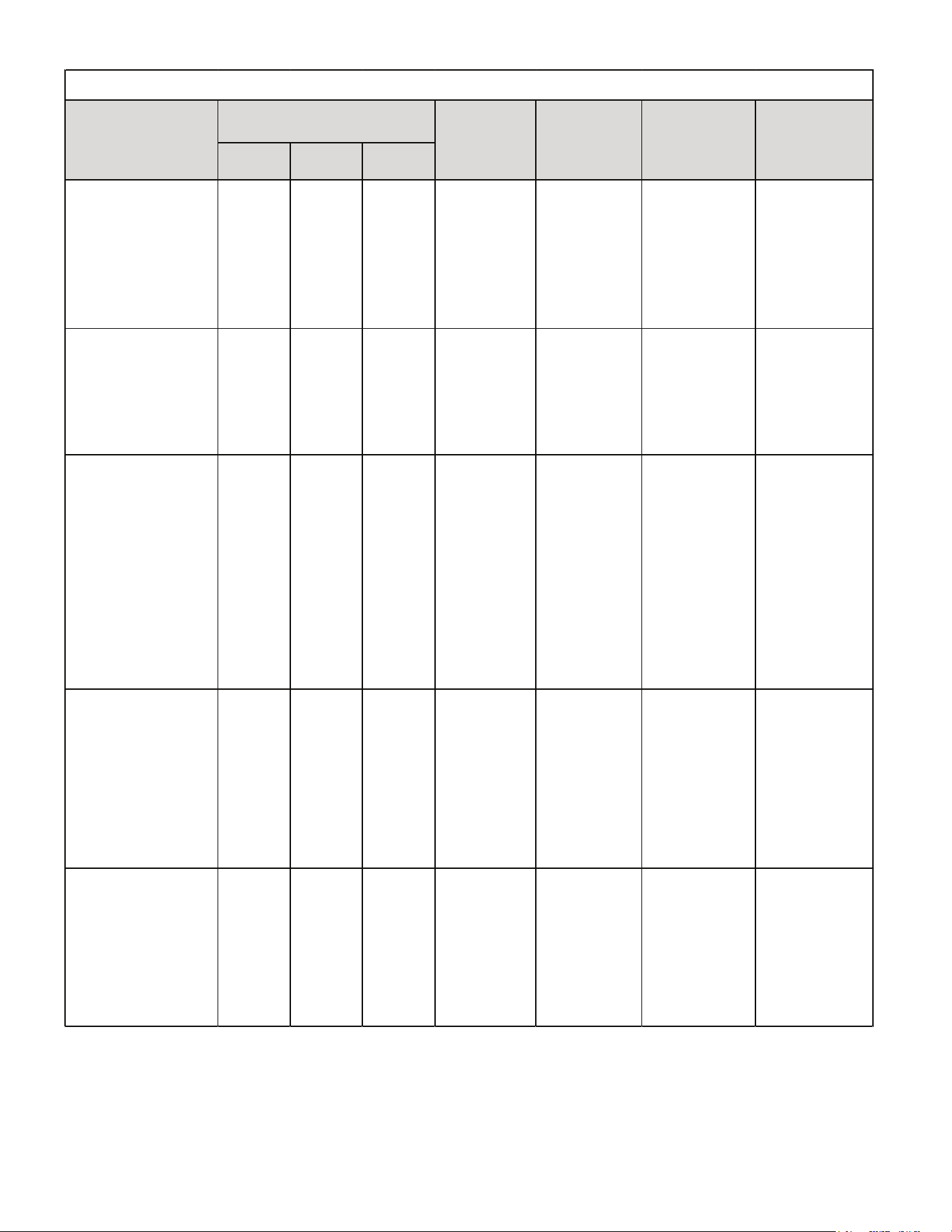
19
TROUBLESHOOTING INFORMATION: UNITARY DIAGNOSTIC CODES
Digit 3 Digit 2 Digit 1
• Air conditioner/heat pump
may appear to be operating
normally.
• Compressor protecor may be
open (compressor and outdoor
fan off).
• Integrated control module
diagnostic/status LED display
shows the indicated code.
BLANK H 8
• High Line Voltage • High line voltage
• Correct high line
voltage condition;
contact local utility if
needed.
• Verify unit is
connected to power
supply as specified on
rating plate.
• Turn power OFF prior
to repair.
• Control detects line
voltage greater than 255
VAC.
• Fault will clear if line
voltage decreases
below 255 VAC.
• Air conditioner/heat pump
may appear to be operating
normally.
• Integrated control module
diagnostic/status LED display
shows the indicated code.
BLANK 0 9
• Low Pilot Voltage
• Control detects
secondary voltage
less than 18 VAC.
• Transformer
overloaded.
• Low line voltage.
• Check fuse.
• Correct low secondary
voltage condition.
• Check transformer;
replace if needed.
• Turn power OFF prior
to repair.
• Fault will clear if
secondary voltage rises
above 21 VAC.
• Replace with correct
replacement part(s).
• Compressor is off.
• Integrated control module
diagnostic/status LED display
shows the indicated code.
BLANK P 0
• Comp protector
Open
• No current through
run or start windings.
• Compressor run
winding is open.
• Compressor not
properly wired to
control.
• Faulty Compressor
wiring.
• Failed compressor
run capacitor.
• Faulty run capacitor
wiring.
• Check compressor;
repair/replace as
needed.
• Check wiring
repair/replaced as
needed.
• Check run capacitor;
replace as needed.
• Turn power OFF prior
to repair.
• Fault will clear after 1
normal cycle.
• Must clear fault by
cycling 24 VAC to
control.
• Replace with correct
replacement part(s).
• Air conditioner/heat pump
may appear to be operating
normally.
• Compressor protecor may be
open (compressor and outdoor
fan off).
• Integrated control module
diagnostic/status LED display
shows the indicated code.
BLANK L 8
• Low Line Voltage • Low line voltage.
• Check circuit
breakers and fuses.
• Verify unit is
connected to power
supply as specified on
rating plate.
• Correct low line
voltage condition;
contact local utility if
needed.
• Turn power OFF prior
to repair.
• Control detects line
voltage less than 1 85
VAC.
• Fault will clear if line
voltage increases above
1 85 VAC.
• Air conditioner/heat pump
may appear to be operating
normally.
• Compressor protecor may be
open (compressor and outdoor
fan off).
• Integrated control module
diagnostic/status LED display
shows the indicated code.
BLANK L 8
• No Line Voltage • No line voltage.
• Check circuit
breakers and fuses.
• Verify unit is
connected to power
supply as specified on
rating plate.
• Turn power OFF prior
to repair.
• Control detects line
voltage less than 1 85
VAC.
• Fault will clear if line
voltage increases above
1 85 VAC.
UNIT ARY DIAGNOST IC CODES
Symptoms of Abnormal
Operation
Diagnostic/Status
LED Display Codes
Fault Description Possible Causes Corrective Actions
Notes &
Cautions
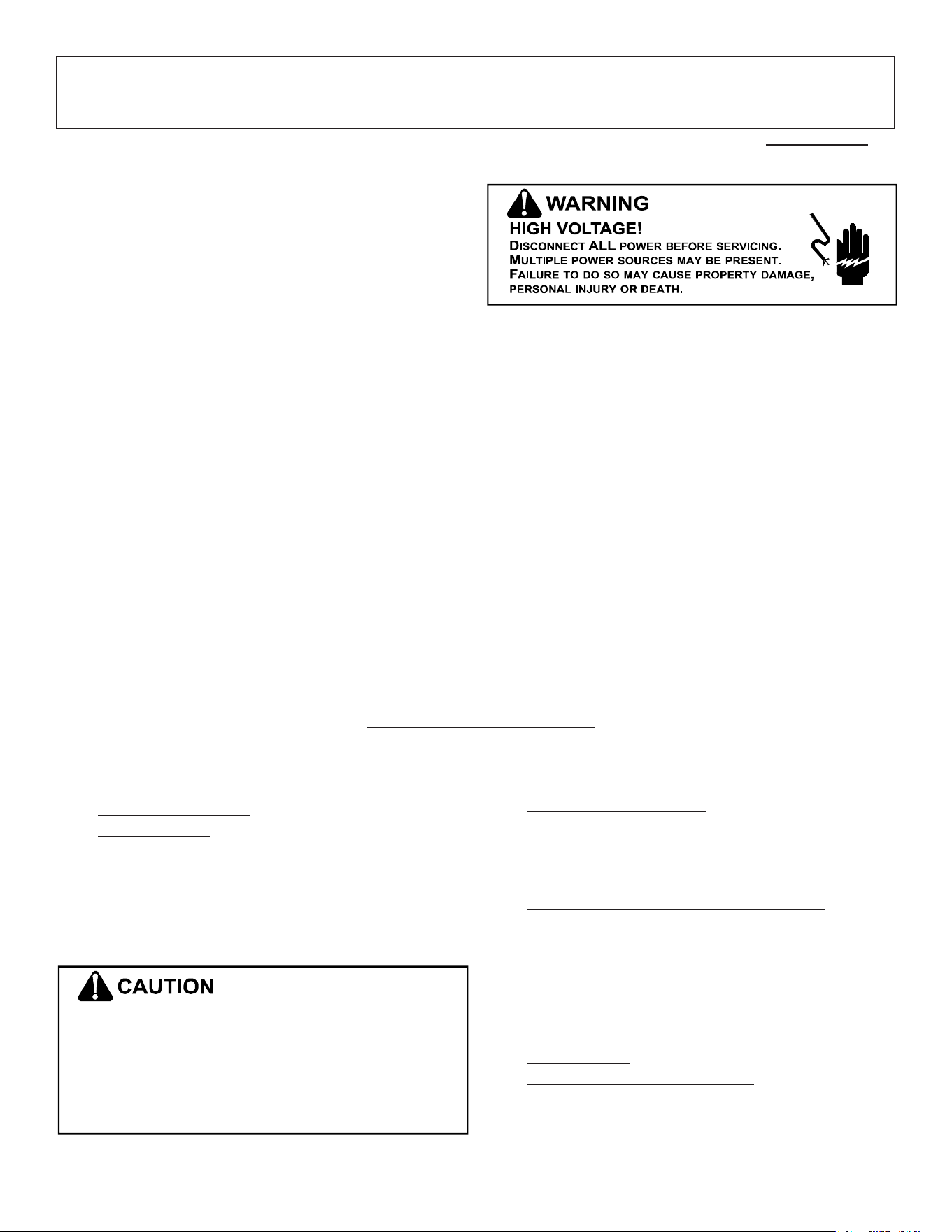
20
SPLIT SYSTEMS
AIR CONDITIONING AND HEAT PUMP HOMEOWNER’S ROUTINE MAINTENANCE RECOMMENDATIONS
We strongly recommend a bi-annual maintenance checkup be performed before the heating and cooling seasons begin by a qualied servicer.
Replace or Clean Filter
IMPORTANT NOTE: Never operate unit without a lter in-
stalled as dust and lint will build up on internal parts resulting
in loss of eciency, equipment damage and possible re.
An indoor air lter must be used with your comfort system.
A properly maintained lter will keep the indoor coil of your
comfort system clean. A dirty coil could cause poor operation
and/or severe equipment damage.
Your air lter or lters could be located in your furnace, in a
blower unit, or in “lter grilles” in your ceiling or walls. The in-
staller of your air conditioner or heat pump can tell you where
your lter(s) are, and how to clean or replace them.
Check your lter(s) at least once a month. When they are dirty,
replace or clean as required. Disposable type lters should
be replaced. Reusable type lters may be cleaned.
You may want to ask your dealer about high eciency lters.
High eciency lters are available in both electronic and
non-electronic types. These lters can do a better job of
catching small airborne particles.
Compressor
The compressor motor is hermetically sealed and does not
require additional oiling.
Motors
Indoor and outdoor fan motors are permanently lubricated
and do not require additional oiling.
Clean Outside Coil (Qualied Servicer Only)
Air must be able to ow through the outdoor unit of your
comfort system. Do not construct a fence near the unit or
build a deck or patio over the unit without rst discussing your
plans with your dealer or other qualied servicer. Restricted
airow could lead to poor operation and/or severe equipment
damage.
Likewise, it is important to keep the outdoor coil clean. Dirt,
leaves, or debris could also restrict the airow. If cleaning of
the outdoor coil becomes necessary, hire a qualied servicer.
Inexperienced people could easily puncture the tubing in the
coil. Even a small hole in the tubing could eventually cause
a large loss of refrigerant. Loss of refrigerant can cause poor
operation and/or severe equipment damage.
Do not use a condensing unit cover to “protect” the outdoor
unit during the winter, unless you rst discuss it with your
dealer. Any cover used must include “breathable” fabric to
avoid moisture buildup.
• Check the thermostat to conrm that it is properly set.
• Wait 15 minutes. Some devices in the outdoor unit or
in programmable thermostats will prevent compressor
operation for awhile, and then reset automatically. Also,
some power companies will install devices which shut
o air conditioners for several minutes on hot days. If
you wait several minutes, the unit may begin operation
on its own.
T
O
AVOID
THE
RISK
OF
EQUIPMENT
DAMAGE
OR
FIRE
,
INSTALL
THE
SAME
AMPERAGE
BREAKER
OR
FUSE
AS
YOU
ARE
REPLACING
. I
F
THE
CIRCUIT
BREAKER
OR
FUSE
SHOULD
OPEN
AGAIN
WITHIN
THIRTY
DAYS
,
CONTACT
A
QUALIFIED
SERVICER
TO
CORRECT
THE
PROBLEM
.
I
F
YOU
REPEATEDLY
RESET
THE
BREAKER
OR
REPLACE
THE
FUSE
WITHOUT
HAVING
THE
PROBLEM
CORRECTED
,
YOU
RUN
THE
RISK
OF
SEVERE
EQUIPMENT
DAMAGE
.
• Check the electrical panel for tripped circuit breakers
or failed fuses. Reset the circuit breakers or replace
fuses as necessary.
• Check the disconnect switch near the indoor furnace
or blower to conrm that it is closed.
• Check for obstructions on the outdoor unit . Conrm
that it has not been covered on the sides or the top.
Remove any obstruction that can be safely removed.
If the unit is covered with dirt or debris, call a qualied
servicer to clean it.
• Check for blockage of the indoor air inlets and outlets.
Conrm that they are open and have not been blocked
by objects (rugs, curtains or furniture).
• Check the lter. If it is dirty, clean or replace it.
• Listen for any unusual noise(s), other than normal
operating noise, that might be coming from the outdoor
unit. If you hear unusual noise(s) coming from the unit,
call a qualied servicer.
Before Calling Your Servicer
21
Condenser / Heat Pump (including all Inverter)
ELECTRICAL (Outdoor Unit)
Line Voltage (Measure L1 and L2 Voltage) L1 - L2
Secondary Voltage (Measure Transformer Output Voltage) NOT ALL MODELS R - C
Compressor Amps
Condenser Fan Amps
TEMPERATURES (Indoor Unit)
Return Air Temperature (Dry bulb / Wet bulb) DB °F WB °F
DB °F WB °F
Delta T (Difference between Supply and Return Temperatures) DB °F
PRESSURES / TEMPERATURES (Outdoor Unit)
Suction Circuit (Pressure / Suction Line Temperature) PSIG TEMP °F
Liquid Circuit (Pressure / Liquid Temperature) PSIG TEMP °F
Outdoor Air Temperature (Dry bulb / Wet bulb) DB °F WB °F
SUPERHEAT / SUBCOOLING SH SC
Line set length in Feet
Additional Refrigerant Charge Added over Factory Charge (Ounces)
Additional Checks
Check wire routings for any rubbing
Check factory wiring and wire connections.
Check product for proper clearances as noted by installtion instructions
°F to °C formula: (°F - 32) divided by 1.8 = °C °C to °F formula: (°C multiplied by 1.8) + 32 = °F
Model Number
Serial Number
Cooling Supply Air Temperature (Dry bulb / Wet bulb)

22
THIS PAGE LEFT INTENTIONALLY BLANK

23
THIS PAGE LEFT INTENTIONALLY BLANK
24
GOODMAN
®
BRAND
AMANA
®
BRAND
PRODUCT REGISTRATION
ank you for your recent purchase. ough not required to get the protection of the
standard warranty, registering your product is a relatively short process, and entitles you
to additional warranty protection, except that failure by California and Quebec residents
to register their product does not diminish their warranty rights. e duration of warranty
coverages in Texas diers in some cases.
For Product Registration, please register as follows:
Goodman
®
Brand products: (https://www.goodmanmfg.com/product-registration).
Amana
®
Brand products: (http://www.amana-hac.com/product-registration).
You can also scan the QR code on the right for the product brand
you purchased to be directed to the Product Registration page.
CUSTOMER FEEDBACK
We are very interested in all product comments.
Please ll out the feedback form on one of the following links:
Goodman
®
Brand Products: (http://www.goodmanmfg.com/about/contact-us).
Amana
®
Brand Products: (http://www.amana-hac.com/about-us/contact-us).
You can also scan the QR code on the right for the product brand
you purchased to be directed to the feedback page.
GOODMAN
®
BRAND
AMANA
®
BRAND
19001 Kermier Rd., Waller, TX 77484
www.goodmanmfg.com • www.amana-hac.com
© 2021-2022 Daikin Comfort Technologies Manufacturing, L.P.
is a registered trademark of Maytag Corporation or its related companies
and is used under license. All rights reserved.


