ODP6000B Series Instruction Manual 1
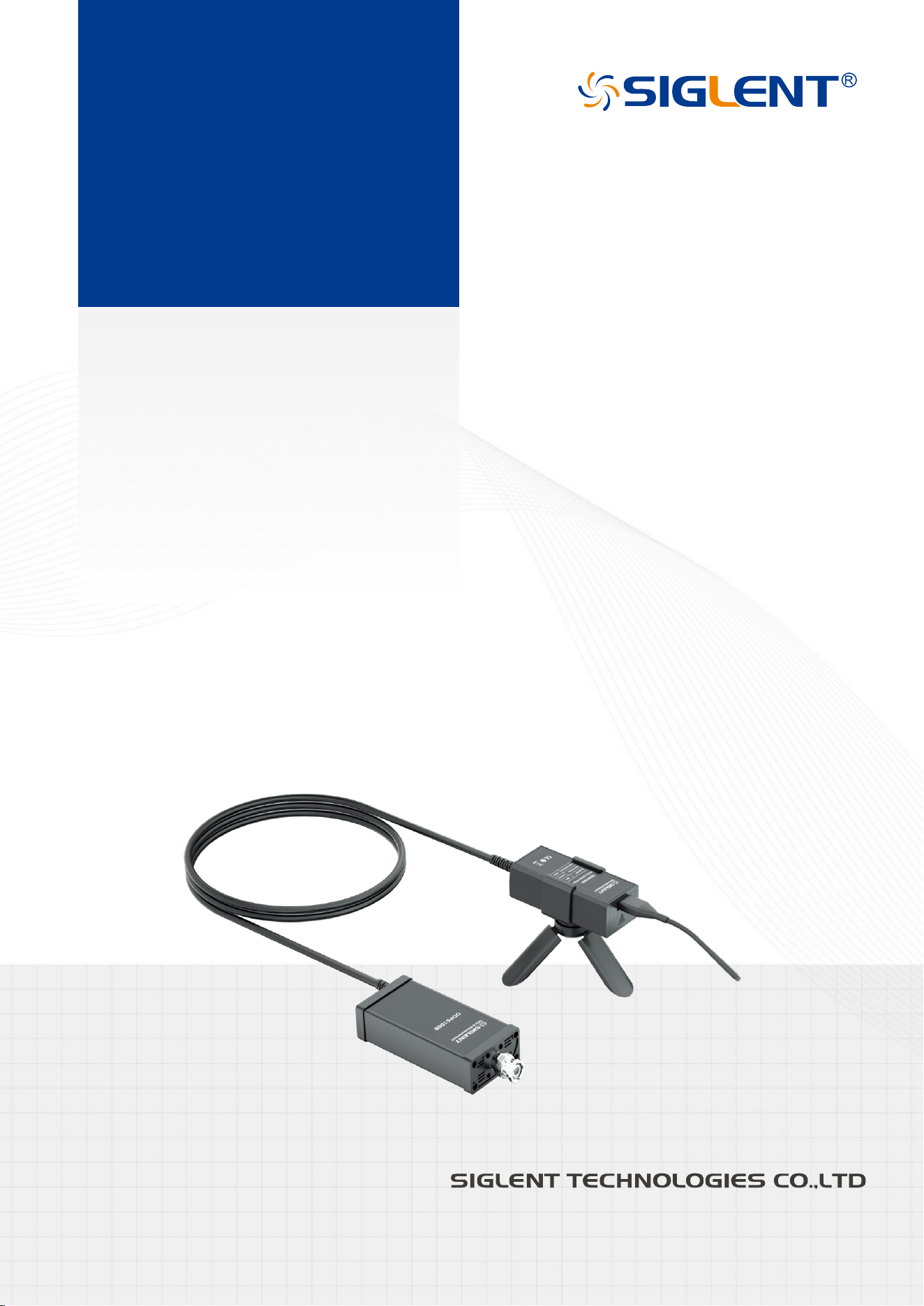
ODP6000B Series
Optical Isolated
Voltage Probe
Instruction Manual
EN01C


ODP6000B Series Instruction Manual 1
Copyright Information
Declaration
SIGLENT products are protected by patent law in and outside of P.R.C.
SIGLENT reserves the right to modify or change parts of or all the specifications or pricing policies at the
company’s sole decision.
Information in this publication replaces all previously corresponding material.
Any method of copying, extracting, or translating the contents of this manual is not allowed without the
permission of SIGLENT.
Note: SIGLENT is the registered trademark of SIGLENT TECHNOLOGIES CO., LTD.

2 ODP6000B Series Instruction Manual
Contents
Copyright Information ..........................................................................................................................1
Preface ....................................................................................................................................................3
Vorwort ...................................................................................................................................................4
Introduction ............................................................................................................................................5
Application .............................................................................................................................................5
Electric Specifications ..........................................................................................................................6
Attenuator Specifications ....................................................................................................................7
Optional Attenuator Packing List .......................................................................................................7
Probe Instruction ...................................................................................................................................8
Battery Description ...............................................................................................................................9
Operating Process ............................................................................................................................. 11
Mechanical Specifications ................................................................................................................ 11
Warranty .............................................................................................................................................. 12
Packing List ......................................................................................................................................... 12
ODP6000B Series Instruction Manual 3
Preface
First of all, thank you for purchasing our products, this instruction manual is the description about the
function, usage, operation attention points, etc. Before use, please read the instructions carefully and use
correctly.
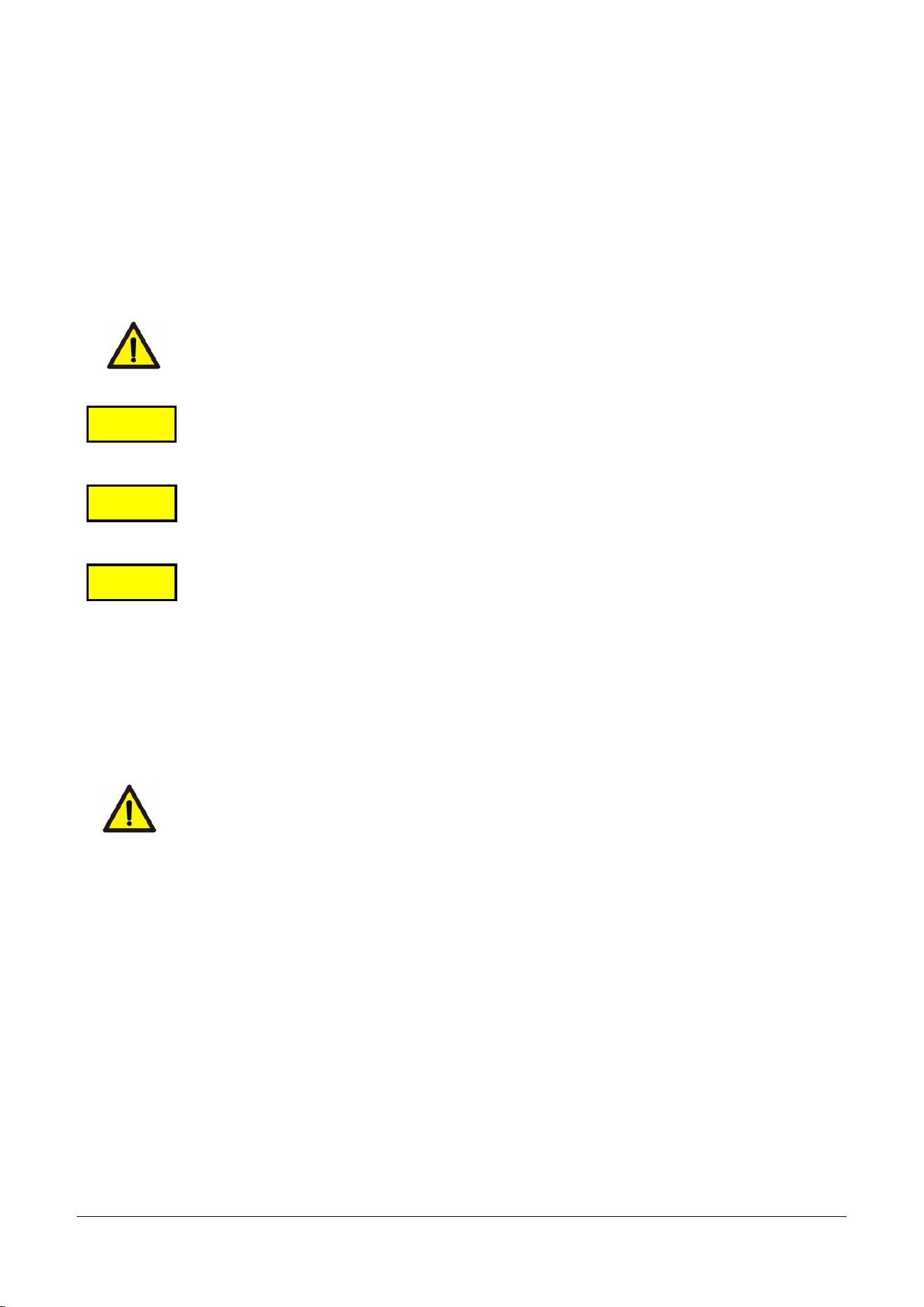
Manual annotation will use the following symbols to distinguish.
This symbol means it is harmful to the machine and human body; you must strictly follow
the instruction manual to operate.
In the case of wrong operation, the user risk injury. The content under this mark records
the relevant matters needing attention to avoid such dangers.
The user may suffer minor injuries and material damage with the wrong operation. To
avoid such situation, the matters under this mark need attention.
This symbolizes important note about how to use the machine.
To the safely use the machine, you must abide by the following safety precautions strictly. The violation
against the manual is likely to damage the protective function of the machine. In addition, the company is
not responsible for any safety problem caused by the violation of matters needing attention in operation.
⚫ Please be careful to the danger of electric shock and pay attention to highest input voltage.
⚫ Do not operate in wet or combustible conditions.
⚫ Make sure the circuit under test is turned off before access it to the probe.
⚫ Turn off the circuit after the measurement, and then remove the probe.
⚫ When BNC cables are connected to the oscilloscope or other instruments, ensure the BNC terminal is
well grounded.
⚫ Check the probe skin and probe lead regularly. If there is any breakage, stop using it immediately.
Warning
Attention
Note
4 ODP6000B Series Instruction Manual
Vorwort
Zunä chst einmal vielen Dank f ü r den Kauf unserer Produkte, diese Bedienungsanleitung ist die
Beschreibung über die Funktion, Verwendung, Bedienung Aufmerksamkeitspunkte, etc. Bitte lesen Sie vor
Gebrauch die Gebrauchsanweisungen sorgfä ltig durch und verwenden Sie sie richtig.
Manuelle Anmerkungen verwenden die folgenden Symbole zur Unterscheidung.
Dieses Symbol bedeutet, dass es schä dlich für die Maschine und den menschlichen
Kö rper ist; Sie müssen die Bedienungsanleitung strikt befolgen, um zu bedienen.
Bei falscher Bedienung riskiert der Benutzer Verletzungen. Der Inhalt unter diesem
Zeichen zeichnet die relevanten Angelegenheiten auf, die beachtet werden müssen, um
solche Gefahren zu vermeiden.
Bei falscher Bedienung kann der Benutzer leichte Verletzungen und Materialschä den
erleiden. Um eine solche Situation zu vermeiden, müssen die Themen unter diesem
Zeichen behandelt werden.
Dies symbolisiert wichtige Hinweise zur Bedienung der Maschine.
Um die Maschine sicher zu benutzen, müssen Sie die folgenden Sicherheitsvorkehrungen strikt einhalten.
Der Verstoß gegen das Handbuch kann die Schutzfunktion der Maschine beschä digen. Darüber hinaus ist
das Unternehmen nicht verantwortlich für Sicherheitsprobleme, die durch die Verletzung von
Angelegenheiten verursacht werden, die im Betrieb Aufmerksamkeit erfordern.
⚫ Bitte achten Sie auf die Gefahr eines Stromschlags und achten Sie auf hö chste Eingangsspannung.
⚫ Nicht unter nassen oder brennbaren Bedingungen arbeiten.
⚫ Stellen Sie sicher, dass der zu prüfende Stromkreis ausgeschaltet ist, bevor Sie ihn zur Sonde greifen.
⚫ Schalten Sie den Stromkreis nach der Messung aus, und entfernen Sie dann die Sonde.
⚫ Wenn BNC-Kabel an das Oszilloskop oder andere Gerä te angeschlossen sind, stellen Sie sicher, dass
die BNC-Klemme gut geerdet ist.
⚫ Ü berprüfen Sie regelmä ßig die Sondenhaut und die Sondenleitung. Wenn es einen Bruch gibt, hö ren
Sie sofort auf, es zu verwenden.
Warning
Attention
Note

ODP6000B Series Instruction Manual 5
Introduction
ODP6000B series is the latest optical isolated voltage probe with remarkably high CMRR. The CMRR of
traditional differential probe decreases fast in high-frequency range, as a result, measuring the small
voltage signal waveform (e.g., the driving voltage when measuring the upper MOSFET of the half-bridge
circuit) under high CM interference voltage accurately become an extremely hard task. ODP6000B series
applies optical isolation technologies and gains remarkably high CMRR in all working bandwidth, helping
our customers to deal with these kinds of challenging measurement with low cost.
Product Characteristics:
⚫ 2 chargeable batteries that can be replaced to keep the probe work continuously.
⚫ Can be calibrated and zeroed online without disconnecting from the tested equipment.
⚫ Multiple attenuators available, able to meet the measurement requirement of different voltage.
⚫ Extremely high CMRR.
⚫ Bandwidth over 1 GHz.
⚫ Isolation voltage over 60 kV.
⚫ High accuracy and stability in wide temperature range.
⚫ Smaller size.
Application
ODP6000B series can be widely applied in the R&D, debugging or maintenance of switching power supply,
motor driver, new energy inverter, converter, LED power supply, household appliances and other electrical
power devices.
⚫ Floating signal test.
⚫ Measure the gate voltage drive of power devices like Si/SiC/GaN.
⚫ Small signal measurement of differential mode under high common mode voltage.

6 ODP6000B Series Instruction Manual
Electric Specifications
Model
ODP6050B
ODP6100B
Bandwidth (-3 dB)
500 MHz
1 GHz
Rise time
≤0.7 ns
≤0.4 ns
Terminal load
50 Ω
50 Ω
Output voltage range
±0.5 V
±0.5 V
Typical values of host noise (Vrms)
1.5 mV
1.5 mV
DC accuracy
≤ ±1%
Isolation voltage
(DC + Peak AC)
±60 kV
Host delay
Around 14 ns
CMRR typical values
(using standard attenuators)
ODP6050B/ODP6100B standard
50X/1000X/2000X/5000X attenuator
DC-10 MHz: 160 dB
10 MHz-100 MHz: 110 dB
100 MHz-300 MHz: 100 dB
300 MHz-500 MHz: 90 dB
500 MHz-800 MHz: 80 dB
800 MHz-1000 MHz: 70 dB
Power supply method
Front end: battery powered, with a working time of
approximately 8 hours and a standby time of
approximately 30 days
Rear end: USB 5 V/2 A
Auto calibration
Yes
Optical fiber length
Around 2 m

ODP6000B Series Instruction Manual 7
Attenuator Specifications
Probe Model
Attenuator Model
Connector Type
Attenuation
Ratio
Measurement
Range
Input
Impedance
ODP6050B
ODP6100B
CK-AT5X-2
SSMB
5:1
±2.5 Vpk
1 MΩ||28 pF
CK-AT10X-2
SSMB
10:1
±5 Vpk
1 MΩ||6 pF
CK-AT20X-2
SSMB
20:1
±10 Vpk
5 MΩ||6 pF
CK-AT50X-2
SSMB
50:1
±25 Vpk
10 MΩ||4 pF
CK-AT100X-2
SSMB
100:1
±50 Vpk
10 MΩ||2 pF
CK-AT200X-2
SSMB
200:1
±100 Vpk
10 MΩ||2 pF
CK-AT500X-2
2.54 mm socket
500:1
±250 Vpk
10 MΩ||2 pF
CK-AT1000X-2
2.54 mm socket
1000:1
±500 Vpk
20 MΩ||2 pF
CK-AT2000X-2
5.08 mm socket
2000:1
±1000 Vpk
20 MΩ||2 pF
CK-AT5000X-2
5.08 mm socket
5000:1
±2500 Vpk
40 MΩ||2 pF
CK-AT10000X-2
5.08 mm socket
10000:1
±5000 Vpk
40 MΩ||2 pF
PS: ODP6050B/ODP6100B with standard CK-AT50X-2 / CK-AT1000X-2 / CK-AT2000X-2 / CK-AT5000X-2;
If you need other models of attenuators, please purchase them independently.
Optional Attenuator Packing List
Connector Type
SSMB
2.54 mm Socket
5.08 mm Socket
CK-201 (2.54_2p)
-
5
-
CK-202 (5.08_2p)
-
-
5
8 ODP6000B Series Instruction Manual
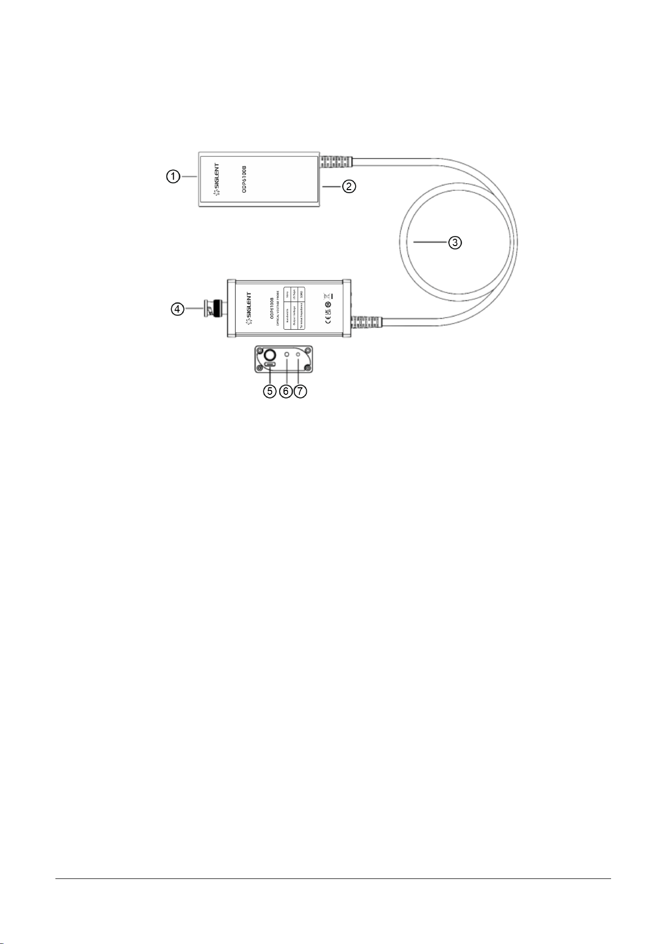
Probe Instruction
① Attenuator input connector: able to connect attenuator on both sides. Please do not forcefully insert
the attenuator, or the connector may be damaged.
② Power supply indicator light: green light means sufficient power; red light means low power.
③ Optical fiber: do not press it heavily or bend it to 90 degrees, or the fiber will be broken.
④ Output connector: standard BNC output connector.
⑤ Power supply connector: please use adaptor and power supply cable of 5 V/2 A. This probe may not
work properly with insufficient power supply.
⑥ Dual color indicator light: the green light blinking means the auto-zero set is ongoing, and if there’s
three beeps and the green light remains, the adjustment is successfully done. However, if the buzzer
sound continuously for 1~2 sec with the green light on, the auto-zero setting is failed. If the red light is
on, the probe is malfunctioned, you would probably need to send it back for maintenance.
⑦ Auto-zero set button: press it lightly to activate the auto-zero set function.
ODP6000B Series Instruction Manual 9
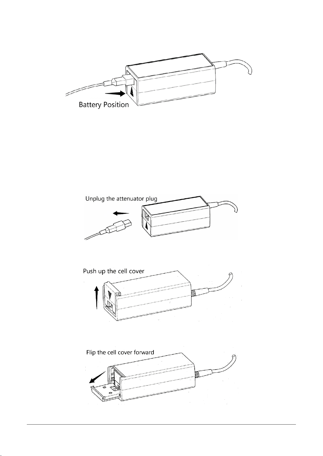
Battery Description
The standard configuration contains two 7.4 V/950 mAh lithium batteries. The battery installation position
is shown in the above figure. In this design, after inserting the attenuator, the attenuator plays a limiting
role and the battery cannot be removed. If you need to remove the battery for charging, refer to the
following steps:
First of all:
Secondly:
Thirdly:
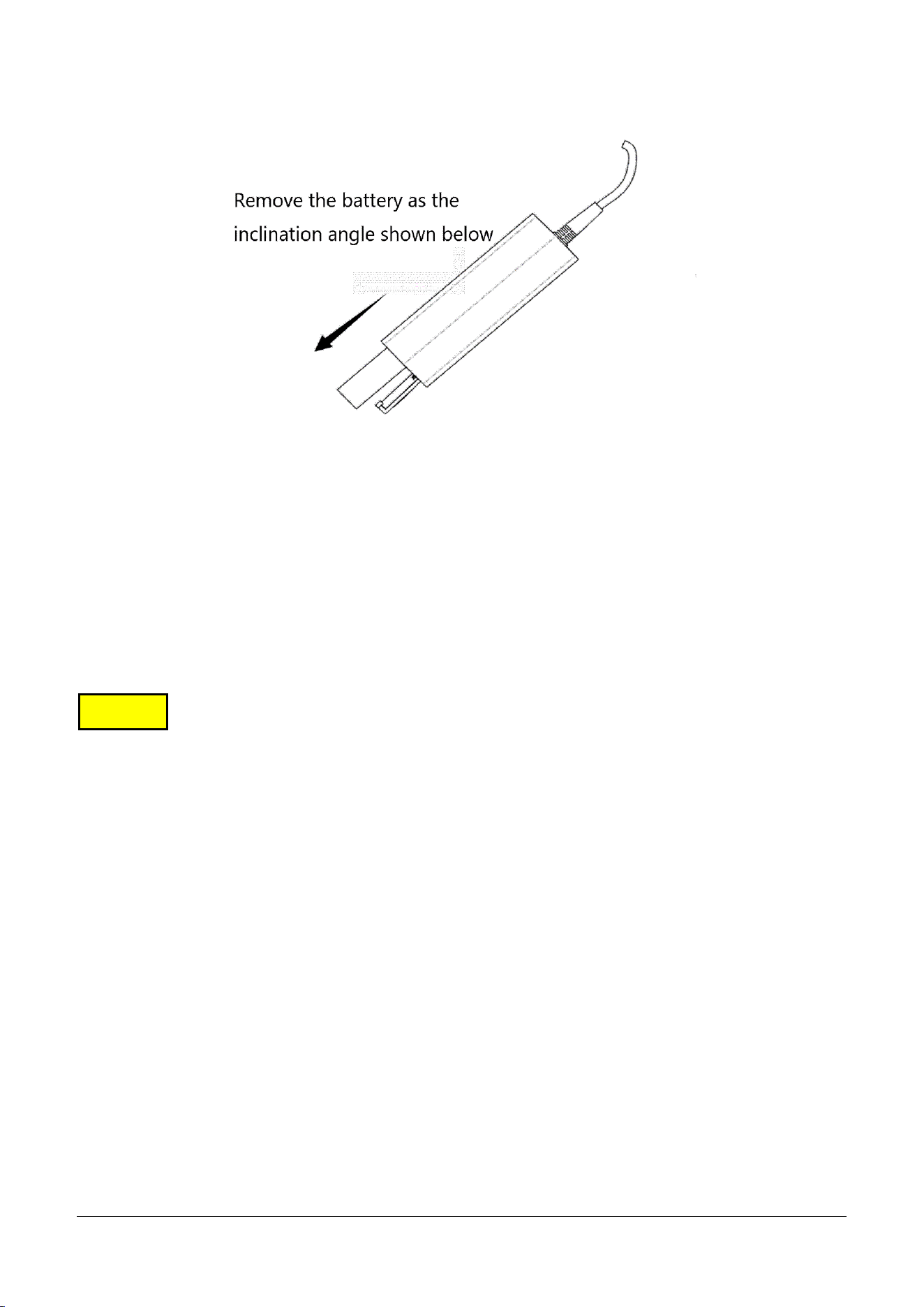
10 ODP6000B Series Instruction Manual
Next:
The ODP6000B series optical isolation probe adopts dual battery replaceable technology to ensure
uninterrupted measurement for customers. Using standard card digital camera lithium batteries, if the
battery fails after several years of use, you can purchase the universal rechargeable battery yourself without
having to send it back to the original factory for replacement. Avoiding possible damage to the probe and
the occupation of measurement time during the shipping process, improving measurement efficiency.
⚫ Do not put heavy object (for instance, your chair) on the optical fiber, avoiding stress on the fiber is
crucial to avoid malfunction.
⚫ Do not squeeze, curl, or bend the optical fiber violently. The diameter of bending should be over 10
cm.
⚫ Do not twist or tie the optical fiber. Do not pull or jerk the optical fiber, especially when there are twists
or knots.
⚫ Do not drop the probe, this could damage the inner optical component.
⚫ Please store the probe in our standard case as we did when you don’t need to use it.
⚫ Please careful exam the optical fiber before usage, and if there’s anything broken, please stop using it
at once.
Note

ODP6000B Series Instruction Manual 11
Operating Process
Please use our standard adaptor and power supply cable.
1 Estimate the range of voltage under test and insert the proper attenuator.
2 Connect the probe to the oscilloscope and power it up. Activate the auto-zero set, it will take about
20 sec depends on the environmental temperature and main component temperature.
3 Set up the attenuation ratio of the oscilloscope accordingly, and adjust the sensitivity of the
oscilloscope according to the voltage under test.
4 Make sure the front end of the probe is elevated if possible, keeping it away from the high voltage
pulse circuit can decrease the interference on the probe.
5 The front end of the probe is directly connected with the high voltage circuit under test. Do not take
the probe off before you turn off the circuit’s power supply.
Mechanical Specifications
Model
Parameter
Probe dimensions
Front-end E/O transmitter
Around 102*45*33 mm
Rear-end O/E receiver
Around 106*49*23 mm
Attenuator length
Around 200 mm
Optical fiber length
Around 2 m
Probe weight
Around 400 g
Attention

12 ODP6000B Series Instruction Manual
Warranty
Please refer to the instruction on the warranty card.
Packing List
Name
ODP6050B
ODP6100B
Voltage probe
1
1
50X attenuator (CK-AT50X-2)
1
1
1000X attenuator (CK-AT1000X-2)
1
1
2000X attenuator (CK-AT2000X-2)
1
1
5000X attenuator (CK-AT5000X-2)
1
1
SSMB male socket to DuPont cable
connector (CK-321)
2
2
SSMB male socket (CK-23)
10
10
2.54 mm socket (CK-201)
5
5
5.08 mm socket (CK-202)
5
5
USB power supply cable TYPE-C 1.5 m
(CK-314A)
1
1
Power supply adaptor 5 V/2 A (CK-605)
2
2
OE transmitter support frame (CK-690A)
1
1
BNC male to SSMB male (CK-25)
1
1
Input extension cable (CK-322)
3
3
Output extension cable (CK-325)
1
1
Battery charger set (CK-691)
1
1
Instruction manual
1
1
Warranty card
1
1
Test report
1
1


Follow us on
Facebook: SiglentTech
Headquarters:
SIGLENT Technologies Co., Ltd
Add: No.26, Lane 2, 1st Liuxian Road,
Bao’an District, Shenzhen 518101, China
Tel: + 86 755 3688 7876
Fax: + 86 755 3359 1582
Email: sale[email protected]
Website: int.siglent.com
North America:
SIGLENT Technologies America, Inc
6557 Cochran Rd Solon, Ohio 44139
Tel: 440-398-5800
Toll Free: 877-515-5551
Fax: 440-399-1211
Email: info@siglentna.com
Website: www.siglentna.com
Europe:
SIGLENT Technologies Germany GmbH
Add: Staetzlinger Str. 70
86165 Augsburg, Germany
Tel: +49(0)-821-666 0 111 0
Fax: +49(0)-821-666 0 111 22
Email: info-eu@siglent.com
Website: www.siglenteu.com