CHIGO CAC FCU
i
Introduction
Part 1 : General Information
Part 2: Indoor Units
Part 3: Installation
Part 4: Control


CHIGO CAC FCU
Introduction
Fan coil unit is a kind of compound device which assemble fan and surface-type coil heating-exchanger
together. Fan coil with fresh air supply system is a main type of center air-conditioner system, so it is an
important component of AC devices. Fan coil has horizontal type, vertical type, etc. A cooling (heating)
supply system usually consists of fan coil terminals and chilled water system (heated water system).
Chigo
®
commercial AC fan coil is designed and manufactured on the base of advanced technology, and
utilize qualified galvanized iron as material. Due to its supper-thin design, it has such advantages: beautiful
outlook, space saving, easy installation, etc. And the most obvious advantage is that it can decrease the
outlet air Temp-difference as low as possible to make room more comfortable, as well as don’t decrease
cooling capacity output. For the large air flow volume design, it can increase room ventilation frequency,
supply more flesh air, and balance room temperature distribution. Benefiting from adoption of advanced
material and technology, it can effectively decrease the running noise and keep running smoothly. With the
advantages above, it can be widely applied in market, hospital, office building, hotel airport, etc.

CHIGO CAC FCU
Part 1: General Information
1. Model Names of Coil
2. External Appearance
3. Nomenclature
4. Features
CHIGO CAC FCU
1. Model Names of Fan Coil
No
Type
Model
Power source
1
Compact Ceiling Cassette Type
CSQ4-300R
220-240V~,1Ph, 50Hz
2
CSQ4-350R
3
CSQ4-470R
4
Ceiling Cassette Type
CSQ-600R
5
CSQ-760R
6
CSQ-880R
7
CSQ-1000R
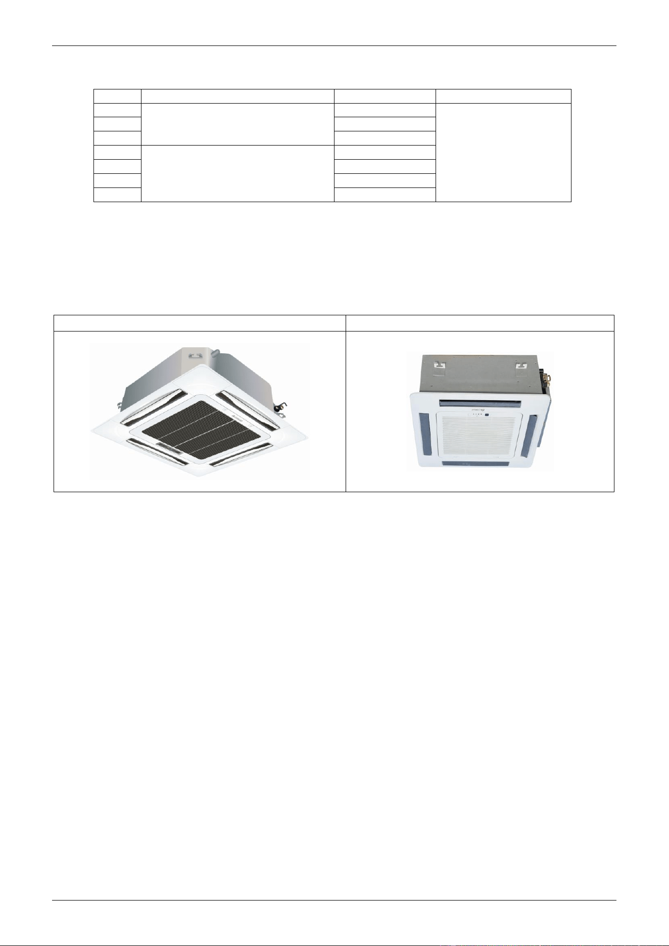
2. External Appearance
Ceiling Cassette Type
Compact Ceiling Cassette Type
CHIGO CAC FCU
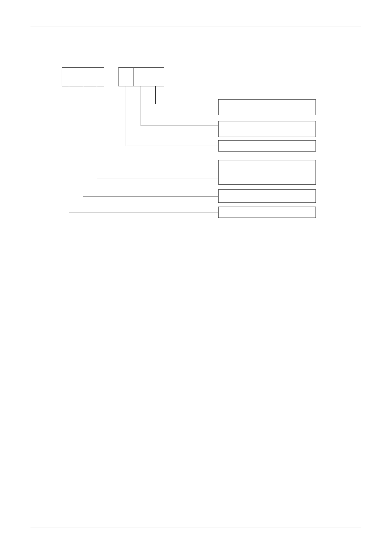
3. Nomenclature
C
P: Static Pressure
12: Static pressure value
R: Remote
W: Wired
-
S
T
600
R
P12
Q: 4-way cassette
Q4: 4-way cassette(compact type)
T: Low ESP Duct
Chigo HVAC
Product series
S: Fan coil unit
Air flow: CFM
4. Features
Chilled water/Hot water (2 pipes)
Low height for easy installation
Low noise fan direct driven by single phase, 3 speed permanent split capacitor motor.
Copper tube/aluminum fin coils
Unit constructed by electrostatic galvanized sheet, providing maximum protection against corrosion

CHIGO CAC FCU
5
Part 2 Indoor Units
1. Ceiling Cassette Type
2. Compact Ceiling Cassette Type

CHIGO CAC FCU
Ceiling Cassette Type
1. Features
2. Specification
3. Dimensions
4. Service Spaces
5. Wiring Diagram
6. Sound Levels
7. Exploded View
8. Troubleshooting
CHIGO CAC FCU
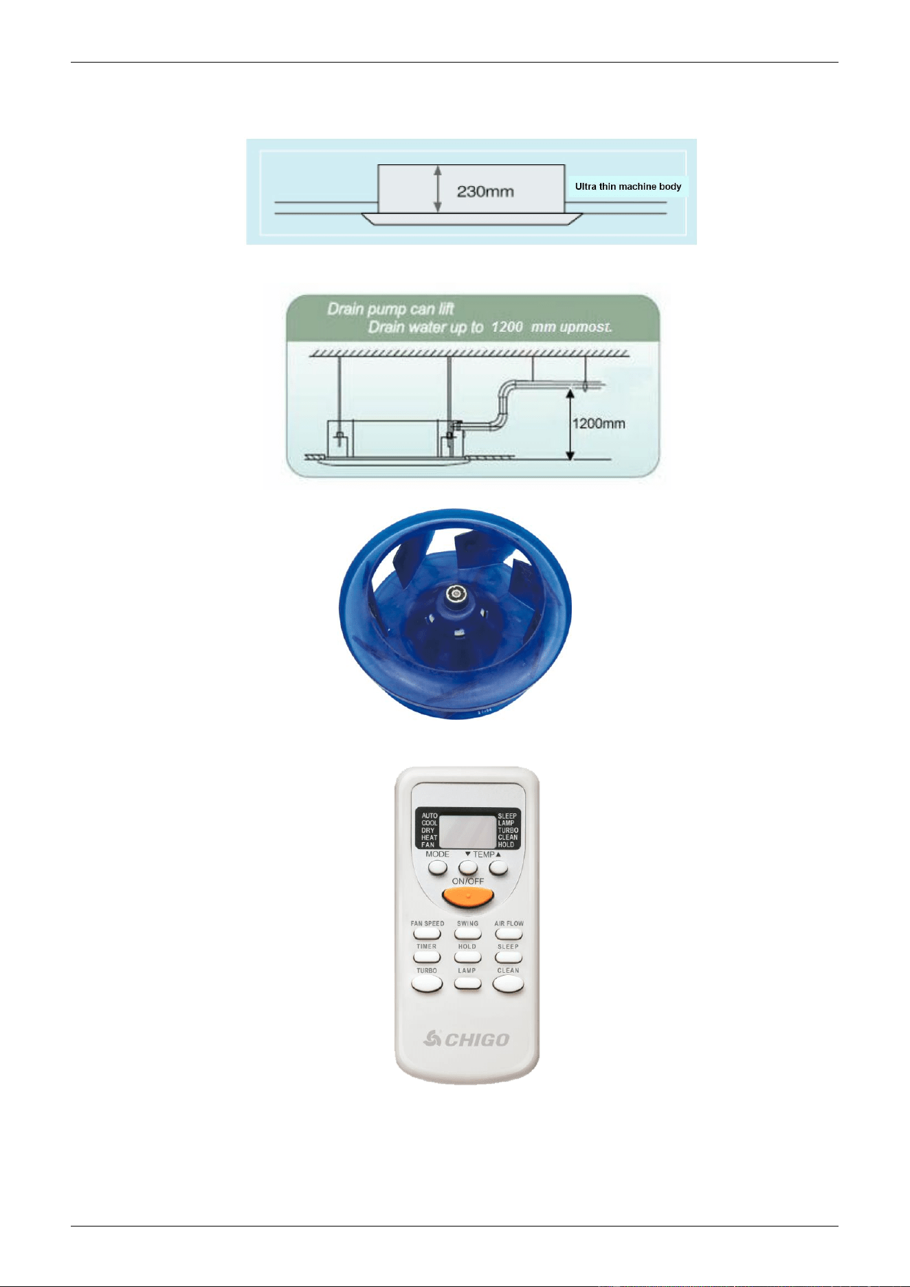
1. Features
1) Ultra thin machine body to easy installation and maintenance. 1000~1300m3/h: 230mm;
1500~1700m3/h: 285mm.
2) Drainage pump can take up the condenser water to 1200mm.
3) Stylish design is harmonious with any interior decoration and creates and elegant environment.
3) A full series of controller give you the most suitable solution according to the different requirement from
different customers.
5) 3-speed motor provides more choices
CHIGO CAC FCU
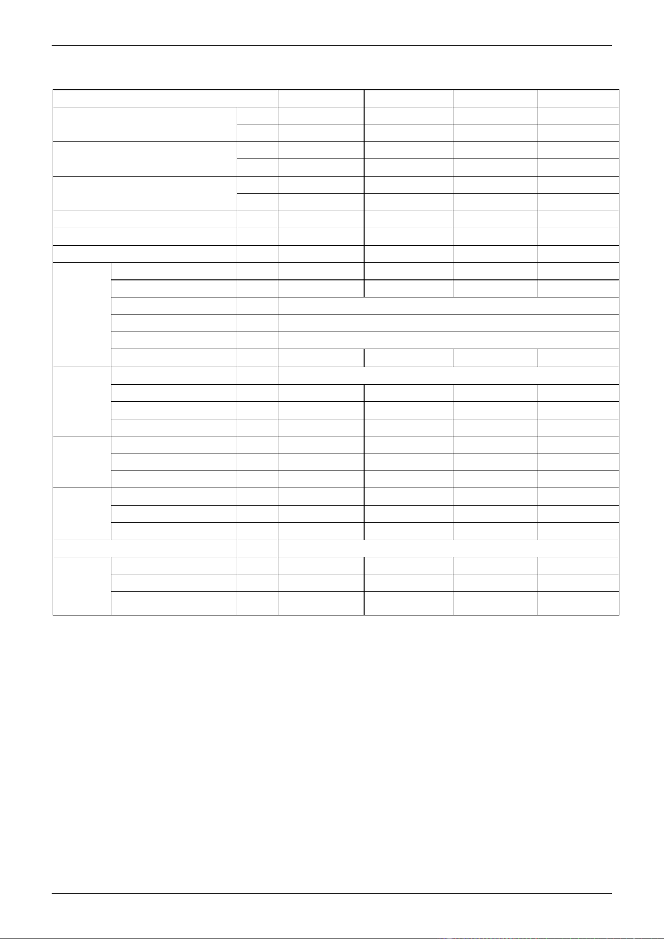
2. Specification
Model NO.
CSQ-600R
CSQ-760R
CSQ-880R
CSQ-1000R
air flow (Hi-speed)
CFM
600
760
880
1000
m3/h
1000
1300
1500
1700
Cooling Capacity (Hi-speed)
W
5300
7200
8500
1000
Btu
18080
24560
29000
34120
Heating Capacity (Hi-speed)
W
8000
10800
12800
15000
Btu
27290
36850
43670
51180
Noise
dB(A)
43-48
44-48
45-52
45-53
Water flow
m3/h
1.1
1.24
1.46
1.55
Water pressure drop
kPa
36
36
38
40
Indoor coil
Number Of Rows
2
2
2
2
Tube Pitch(A)x Row Pitch
mm
21×13.37
21×12.7
21×12.7
21×12.7
Fin spacing
mm
1.45
Fin type
Hydrophilic aluminum
Tube Outside Dia.And type
mm
φ7,Inner grooved tube
Coil Dimension (L×H×W)
mm
2000×168×32
2000×168×32
2000×252×32
2000×252×32
Fan motor
type
Low noise 3-speed fan motor
Number
1
1
1
1
Input
W
140
150
160
180
Capacitor
μF
3
3
4
4
Indoor unit
Dimension (W×H×D)
mm
840×230×840
840×230×840
840×285×840
840×285×840
Packing (W×H×D)
mm
920×265×920
920×265×920
920×310×920
920×310×920
Net/Gross weight
kg
23/28
23/28
26/31.5
28/33.5
plane
Dimension (W×H×D)
mm
950×50×950
950×50×950
950×50×950
950×50×950
Packing (W×H×D)
mm
1030×105×1030
1030×105×1030
1030×105×1030
1030×105×1030
Net/Gross weight
kg
5.4/8
5.4/8
5.4/8
5.4/8
Control Mode
wired controller(optional),remote controller(standard)
Pipe
water-inlet pipe
mm
DN20
DN20
DN20
DN20
water-return pipe
mm
DN20
DN20
DN20
DN20
Condensation water-outlet
pipe
mm
DN25
DN25
DN25
DN25
Remark: 1. All performance data above is based upon 0Pa ambient static pressure.
2. Cooling capacity test condition: air inlet Temp. : 27DB℃/19WB℃, water inlet Temp. 7℃, water Temp. difference
5℃.
3. Heating capacity test condition: Air inlet Temp. 21DB℃, water inlet Temp. 60 DB℃, water Temp. difference
5℃.
CHIGO CAC FCU
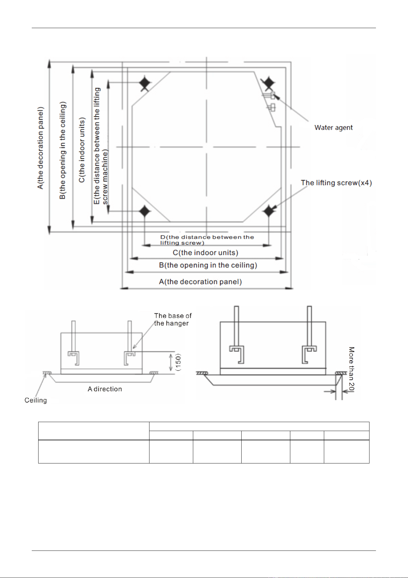
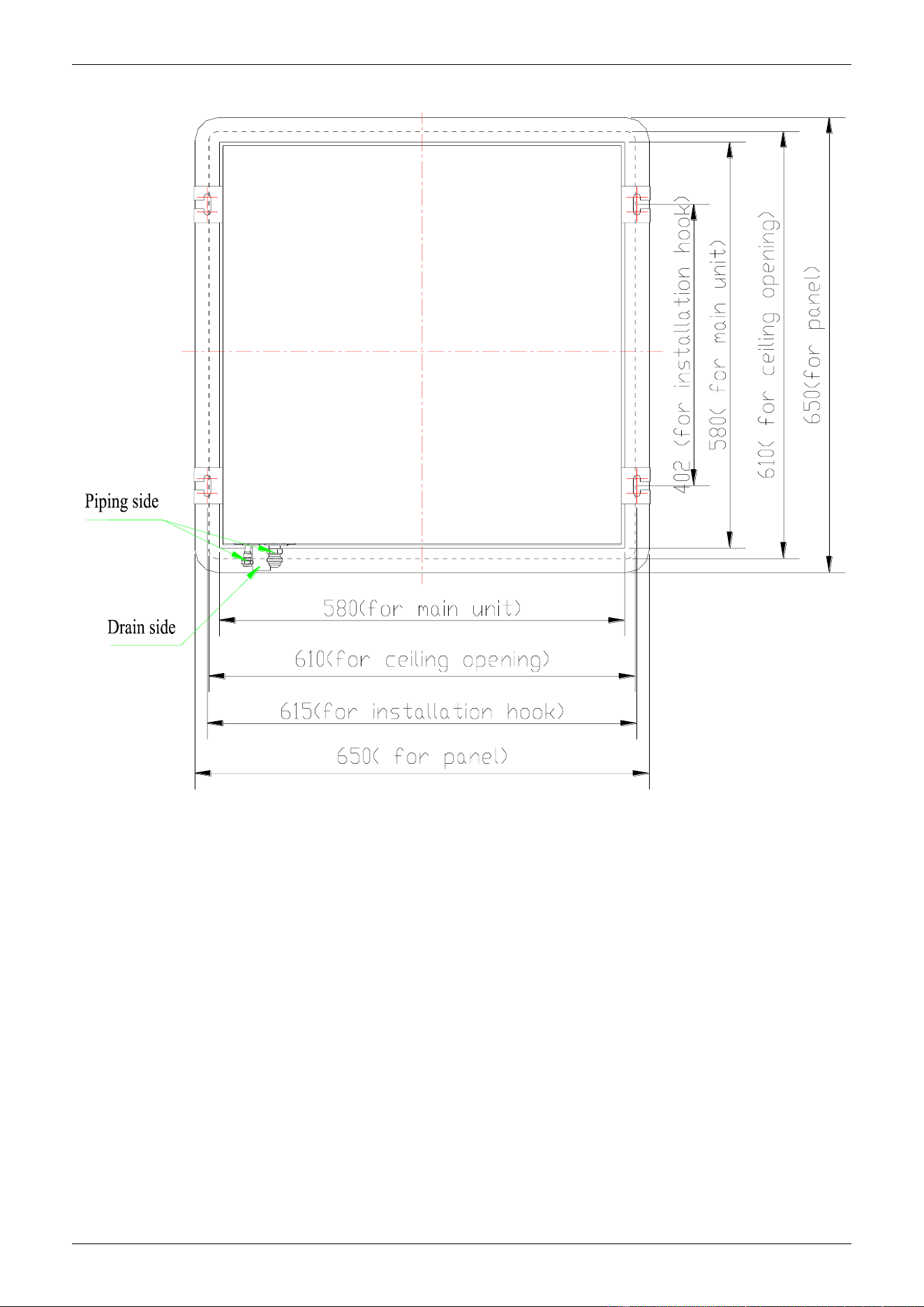
3. Dimensions
Unit: mm
Model
Dimensions(H)
A
B
C
D
E
CSQ-600R CSQ760R
CSQ-880R CSQ-1000R
950
890
840
680
780
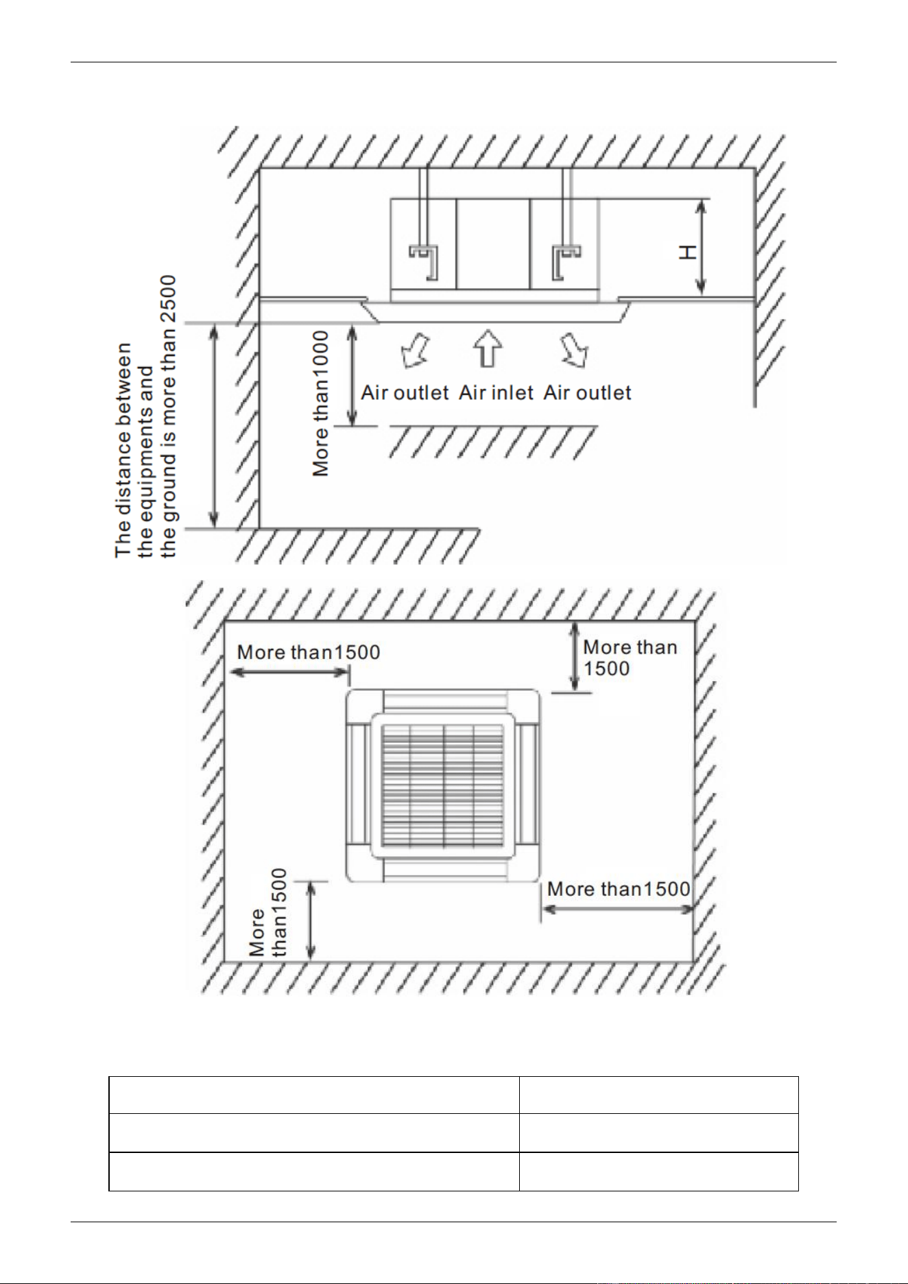
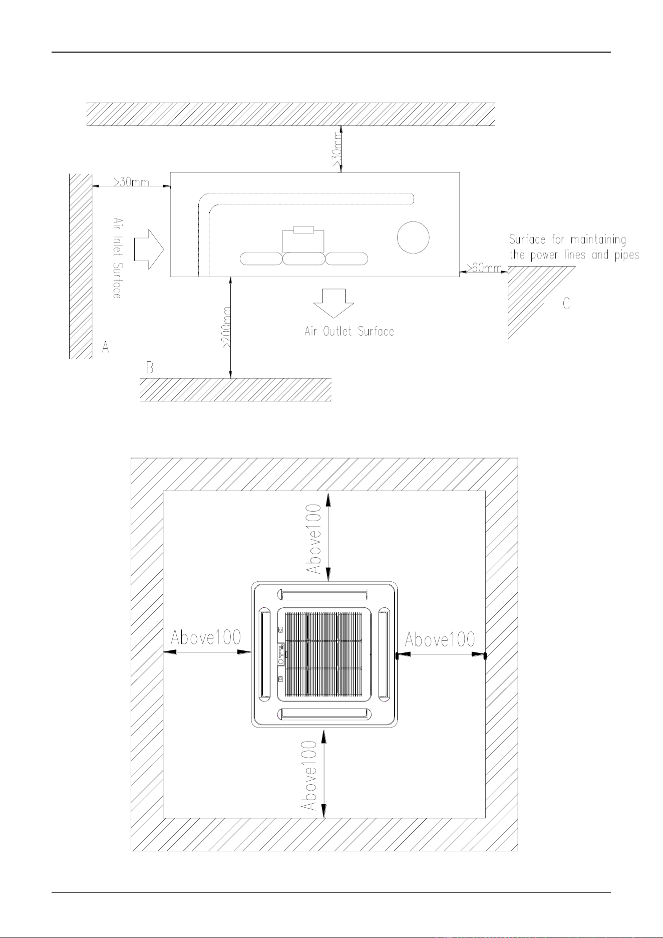
CHIGO CAC FCU
4. Service Spaces
Installation dimension
Model
Dimensions(H) (mm)
CSQ-600R CSQ-760R
230
CSQ-880R CSQ-1000R
285
CHIGO CAC FCU
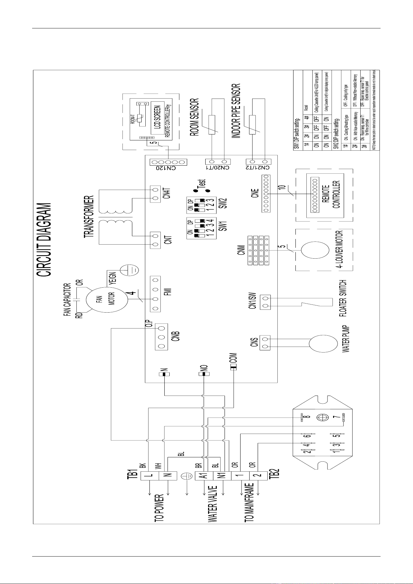
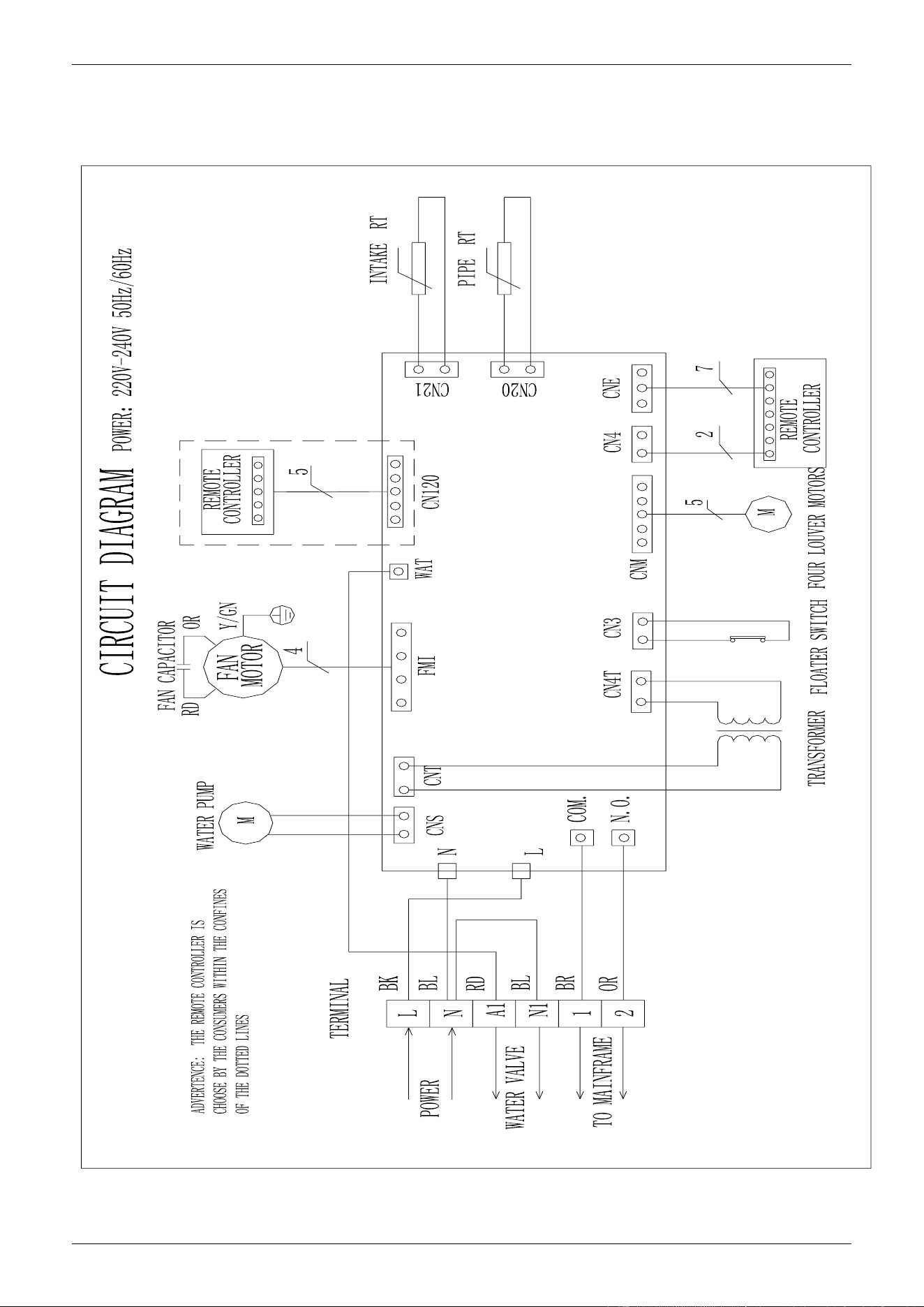
5. Wiring Diagram
CSQ-600R, CSQ-760R,CSQ-880R, CSQ-1000R
CHIGO CAC FCU
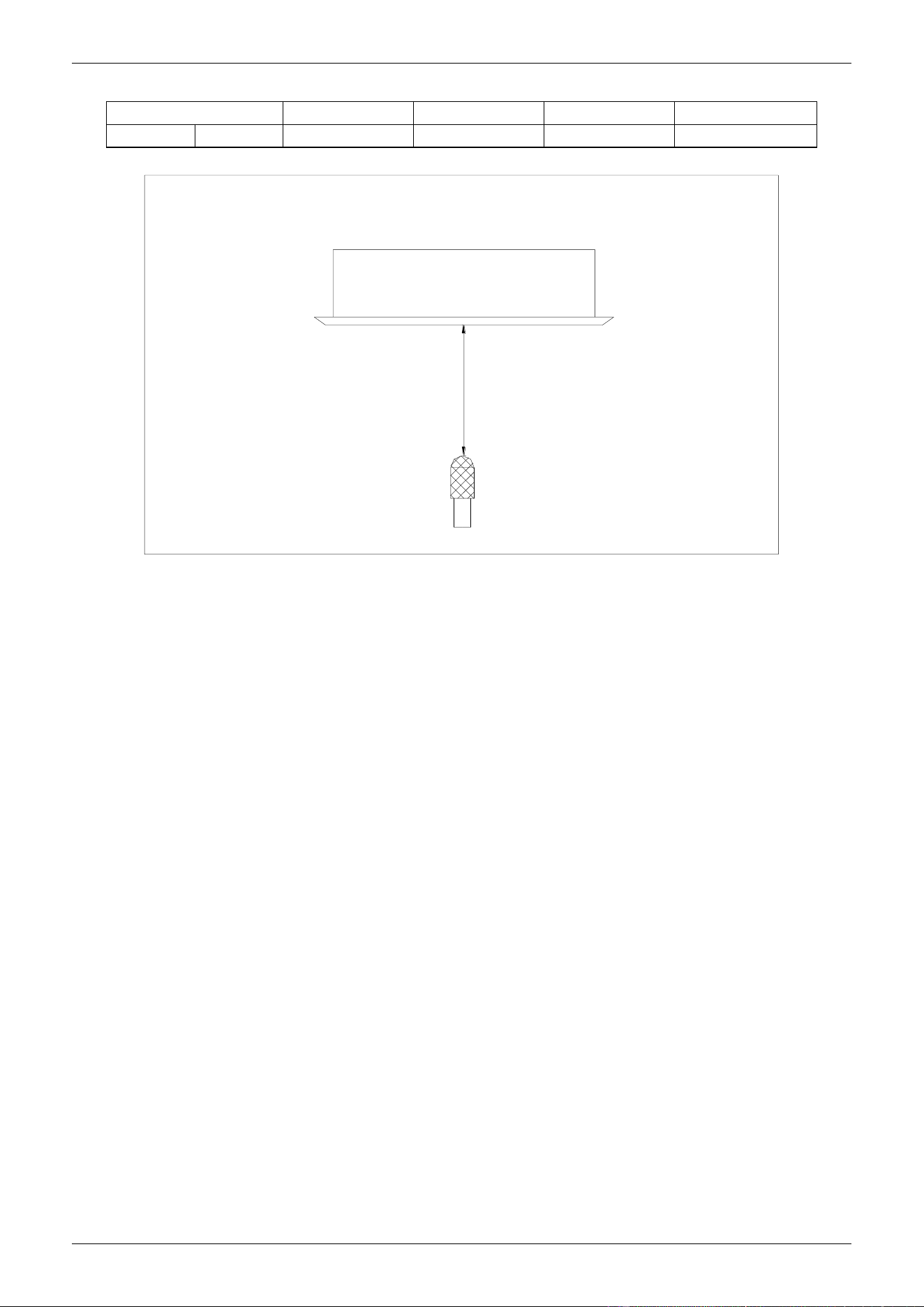
6. Sound Levels
Model
CSQ-600R
CSQ-760R
CSQ-880R
CSQ-1000R
Noise
dB(A)
43-48
44-48
45-52
45-53
FOUR-WAY CASSETTE TYPE
Microphone
1.0m
CHIGO CAC FCU
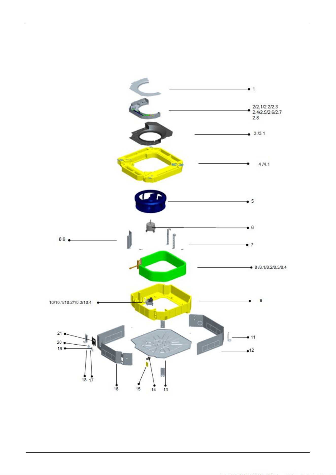
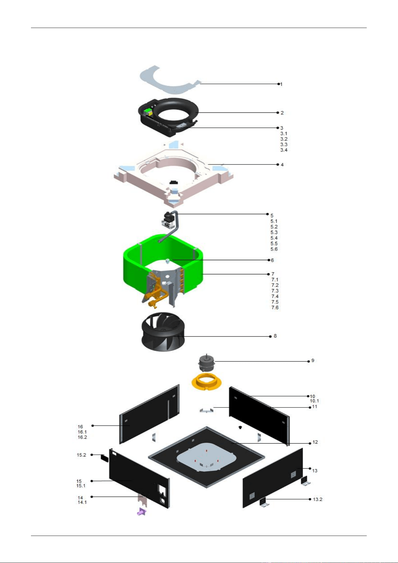
7. Exploded View
CSQ-600R, CSQ-760R,CSQ-880R, CSQ-1000R
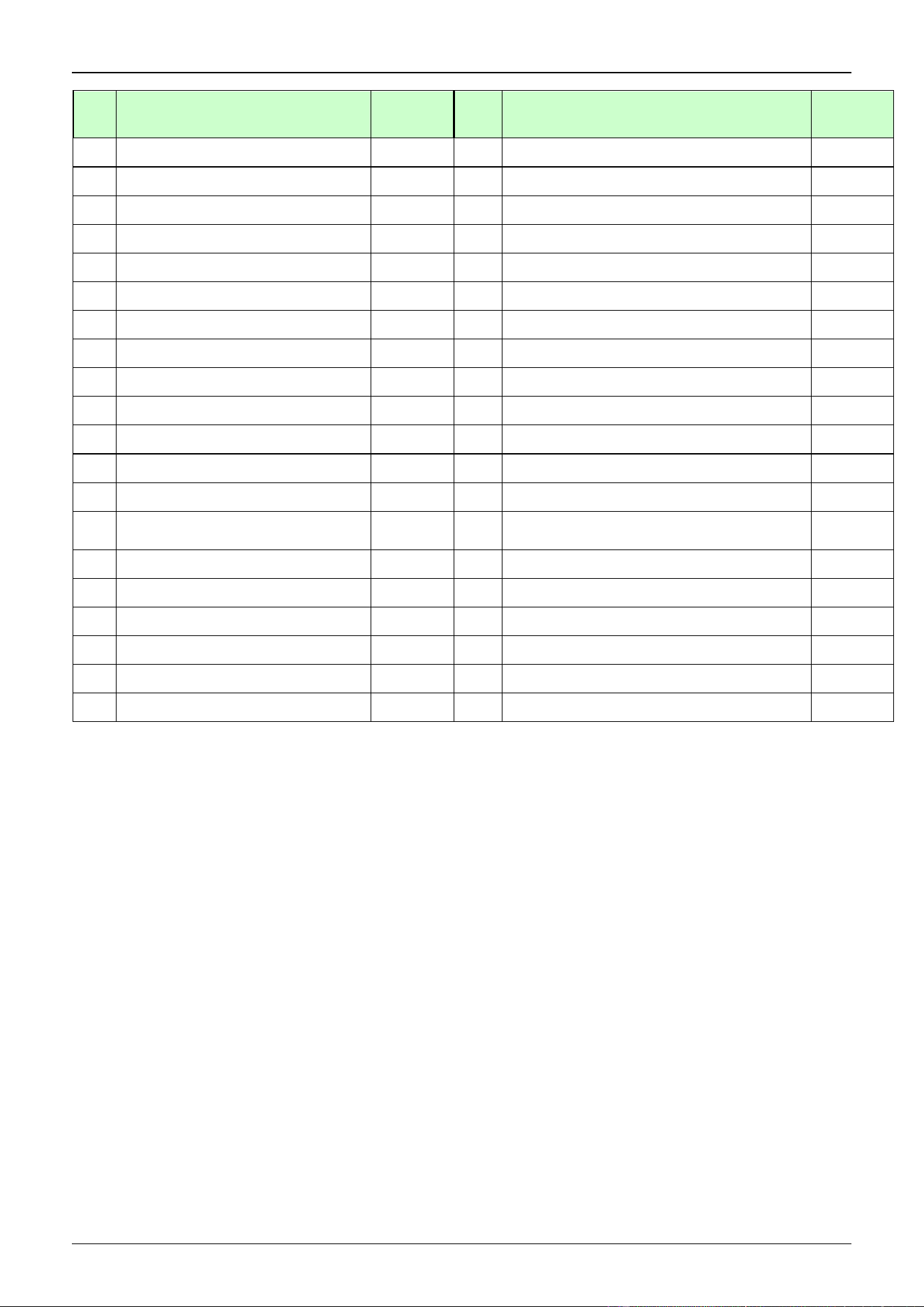
CHIGO CAC FCU
No.
Part Name
Quantity
No.
Part Name
Quantity
1
E-parts box cover
1
8.3.2
Evaporator
1
2
Electrical control components for
indoor unit
1
8.3.3
Water inlet pipe welding assy
1
2.1
transformer
1
8.3.4
Drain pipe welding assy
1
2.2
Fan motor capacitor
1
8.4
Main fixing board
1
2.3
Terminal
1
9
Upper foam components
1
2.4
Terminal
1
10
Pre-assembling assy for water pump
1
2.5
E-parts board for indoor unit
1
10.1
water pump support
1
2.6
Temperature sensor
1
10.2
Water pump
1
2.7
Temperature sensor
1
10.3
Liquid-level sensor
1
2.8
Welded chasis for E-parts box
1
10.4
Underlay for water pump support
3
3
Wind inlet guide assy
1
11
Hanger
4
3.1
Wind inlet guide
1
12
Rear brattice
1
4
Water pan components
1
13
Chassis assy
1
4.1
Foam pendant
2
14
Discharge pipe joint
1
5
Centrifugal fan
1
15
Side maintenance board for water
pump
1
6
Fan motor for indoor
unit(YDK-55T-6-1)
1
16
Front brattice
1
7
Auxiliary fixing board for
evaporator
2
17
Lower pipe clamp
1
8
Evaporator components
1
18
Lower pipe clamp(φ35)
1
8.1
Insulating pipe
2
19
Upper pipe clamp
1
8.2
Evaporator attached cotton
1
20
Upper pipe clamp(φ35)
1
8.3
Evaporator welding assy
1
21
Valve panel
1
8.3.1
Instalation tube for probe
1
CHIGO CAC FCU
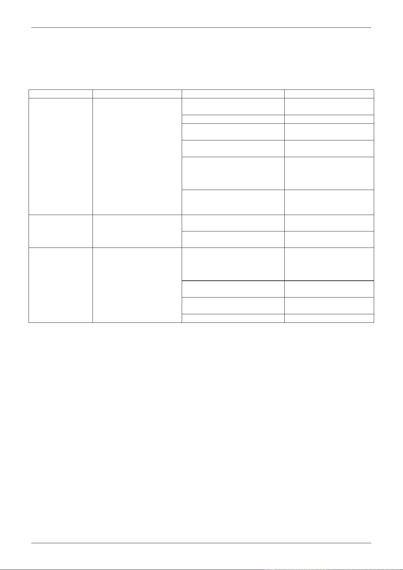
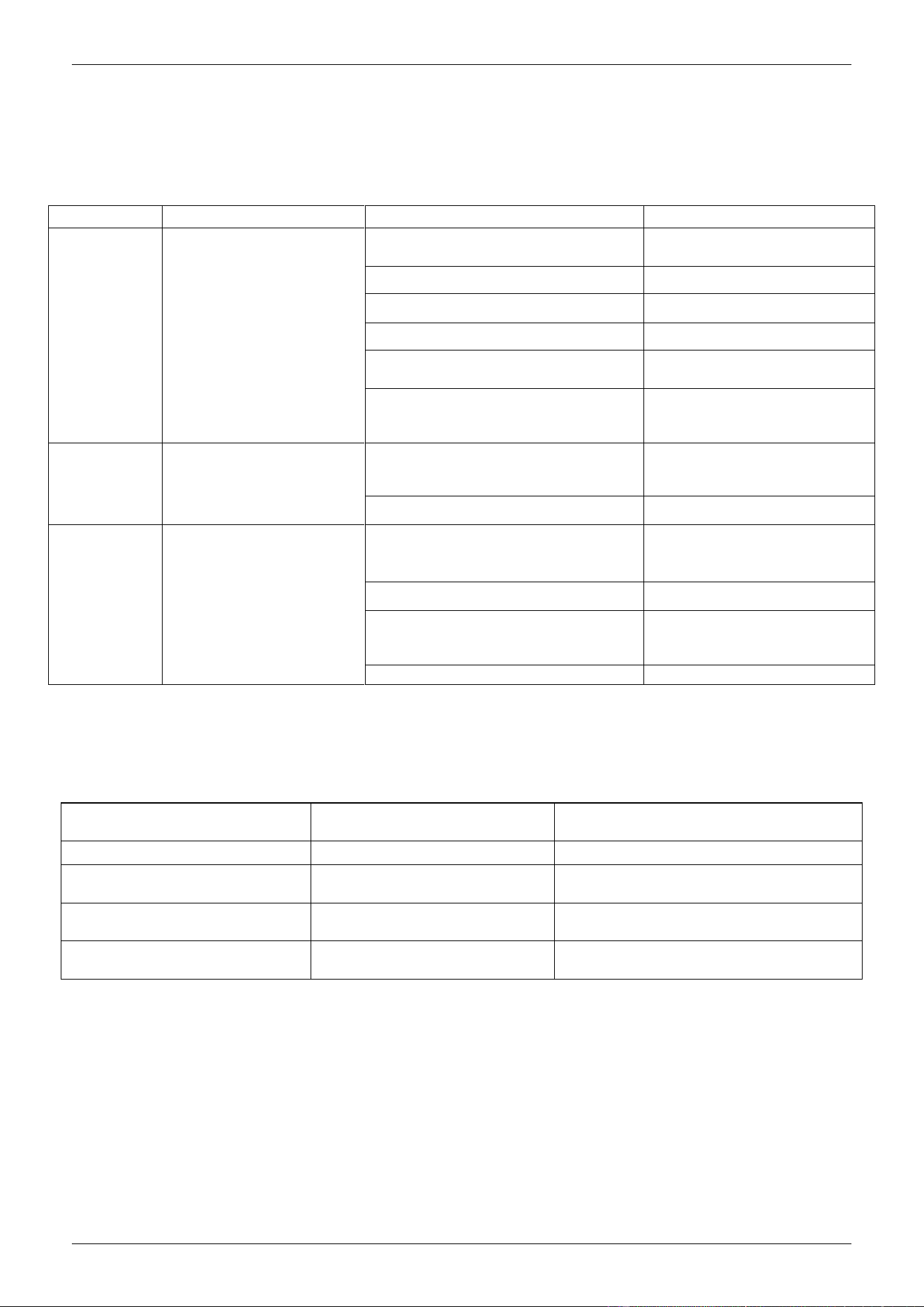
8. Troubleshooting
Problem Analysis
If the air conditioner is out of work, read the following before contacting the maintenance
department and it will save you time and efforts.
Problems
Phenomenna
Causes
Solution
Air conditioner
fails to run
Press "ON/OFF"key on
the remote controller, no
"beep "sound comes from
the indoor unit and the
RUN light is off
Power failure
Press“ON/OFF”key after
comeback of power
Power switch is off
Turn on power supply
Fuse of power switch may
have burned.
Replace the fuse
The creepage switch is off
Turn on the creepage
switch
The remote controller is
working out of the
function range
Operate the remote
controller in the function
range of the remote
controller
Batteries of remote controller
exhausted(Information on the
screen darken)
Replace them with new
batteries
After starting up,
the air conditioner
will stop working
in a short time
Remote controller
indicates that the air
conditioner is
working
Air inlet or outlet of the indoor
or outdoor unit are blocked
Eliminate all dirties and
make air smooth.
The air filter is dirt
Clean the filter
Air flow is normal
but the air blew
out is not cool
or warm
Remote controller
indicates that the air
conditioner is working
Temperature is not set
correctly, too high in COOL
mode or too low in HEAT
mode
Set the temperature
properly.
The air filter net has been
blocked with dust or dirt
Clean the ail filter net
Air inlet or outlet of the indoor
or outdoor unit are blocked
Eliminate all dirties and
make air smooth.
Doors and windows are open
Close doors and windows
NOTE: If the unit stops running due to power failure, it will not restart when the power is resumed. To restart
again, press ON/OFF switch of the remote controller.
CHIGO CAC FCU
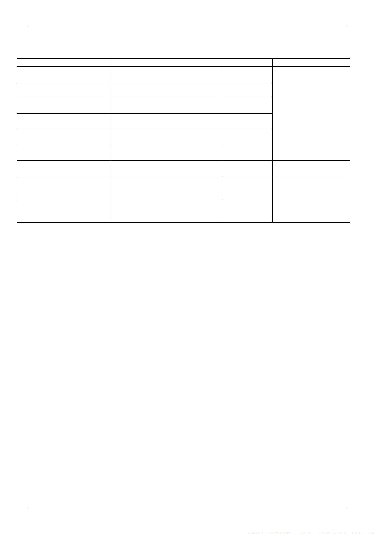
Fault codes table(1)
Faults
LED flashing conditions
Digital display
Instruction
Probe of Room temp.sensor
goes wrong
TIMER lamp flashes at the speed of
5 Hz
E2
The system will recover
normal operation once
faults are eliminated
Probe of Evaporator sensor
goes wrong
RUN lamp flashes at the speed of 5
Hz
E3
Probe of Condenser sensor
goes wrong
Defrost lamp flashes at the speed of
5 Hz
E5
Water fulfilled protection
Warning light flashes at the speed
of 5 Hz
F5
Outdoor unit protection
Both defrost lamp and warning light
flash at the speed of 5 Hz
F2
Communication fault
Both RUN lamp and defrost lamp
flash at the speed of 5 Hz
E1
The display should be
cleared up by manual
EEPROM Communication
fault
Both RUN lamp and TIMER lamp
flash at the speed of 5 Hz
P6
Recovered after
blackout
Forced cooling indication
Both RUN lamp and warning light
flash at the speed of 5 Hz
No
The display will be
cleared up after exiting
the operating mode.
Anti-cold wind indication in
heating mode
Defrosting preheating is ON
P1
The display will be
cleared up after exiting
the operating mode.

Compact Ceiling Cassette Type
1. Features
2. Specification
3. Dimensions
4. Services Space
5. Wiring Diagram
6. Sound Levels
7. Exploded view
8. Troubleshooting
1. Features
1) Low operation noise
---Streamline plate ensures quietness
---Creates natural and comfortable environment
2) The adoption of the most advanced 3- Dimensional Screw fan
---Reduces the air resistance passing through
---Smoothes the air flow
---Makes air speed distribution to the heat exchange uniform
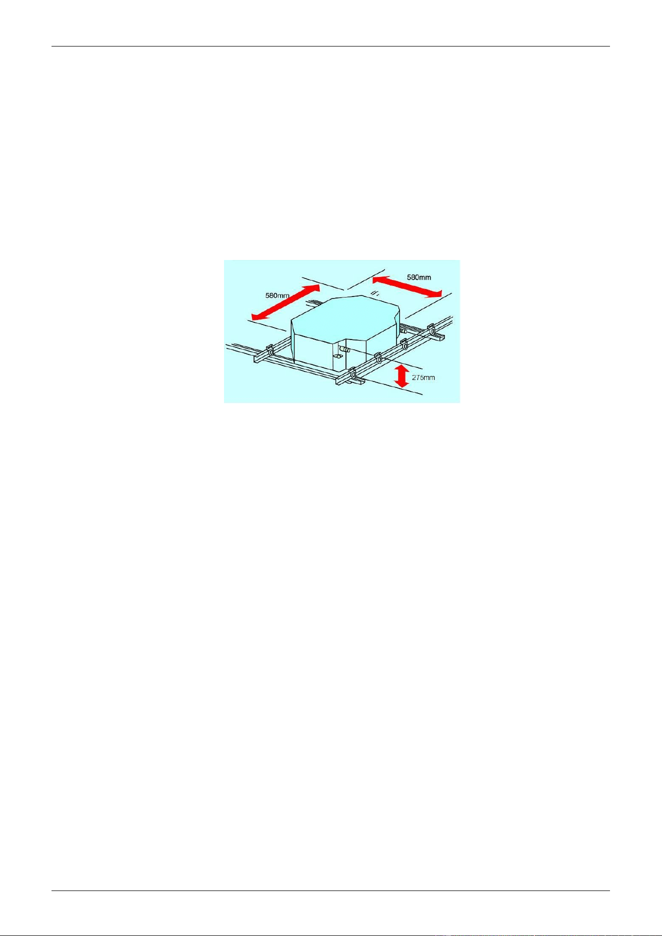
3) Improvement for easy installation and maintenance
---Little space is required for installation into a shallow ceiling
---Because of the compactness and weight reduction of the main unit and panel, all models can be
installed without a hoist
The sketch of installation (compact type)
4) A full series of controller give you the most suitable solution according to the different requirement
from different customers.
5) Optimized structure makes the air volume and capacity improved rapidly.
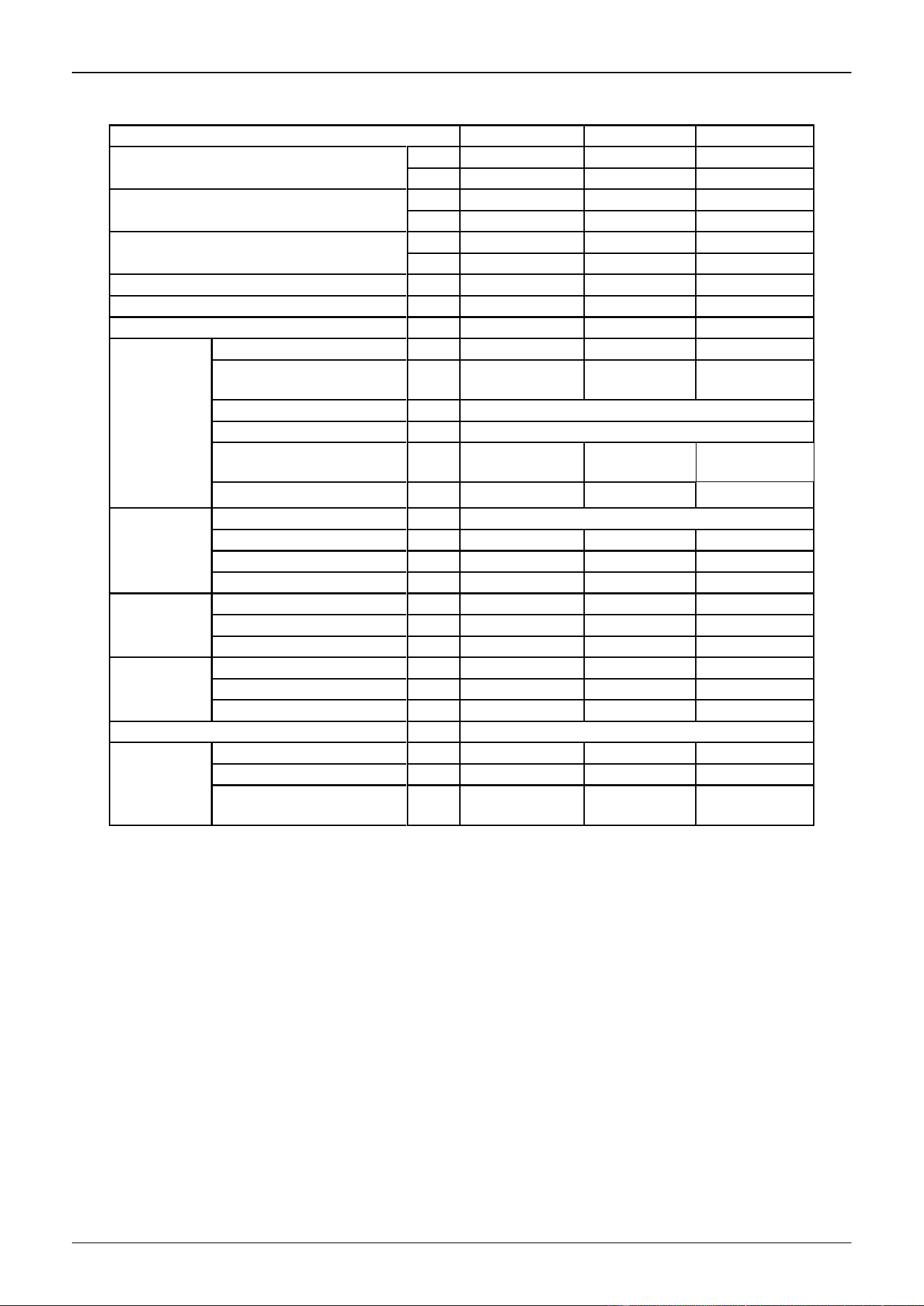
2. Specification
Model NO.
CSQ4-300R
CSQ4-350R
CSQ4-470R
Air flow (Hi-speed)
CFM
300
350
470
m3/h
500
600
800
Cooling Capacity (Hi-speed)
W
2800
3500
4500
Btu
9550
11940
15350
Heating Capacity (Hi-speed)
W
4200
5300
6800
Btu
14330
18080
23200
Noise (Hi-speed)
dB(A)
40
44
44
Water flow
m3/h
0.48
0.60
0.78
Water pressure drop
kPa
25
28
30
Indoor coil
Number Of Rows
2
2
2
Tube Pitch(A)x Row Pitch(B)
mm
25.4×22
21×12.7
21×12.7
Fin spacing
mm
1.55
Fin type
Hydrophilic aluminum
Tube Outside Dia.And type
mm
φ9.52, inner
grooved tube
φ7, inner
grooved tube
φ7, inner
grooved tube
Coil Dimension (L×H×W)
mm
425x203.2×22
435×210×25.4
435×210×25.4
Fan motor
type
Low noise 3-speed fan motor
Number
1
1
1
Input
W
43
64
65
Capacitor
μF
2
2
2.5
Indoor unit
Dimension (W×H×D)
mm
580×275×580
580×275×580
580×275×580
Packing (W×H×D)
mm
745×350×675
745×350×675
745×350×675
Net/Gross weight
Kg
22/24
22/24
22/24
plane
Dimension (W×H×D)
mm
650×30×650
650×30×650
650×30×650
Packing (W×H×D)
mm
710x120x710
710x120x710
710x120x710
Net/Gross weight
Kg
2.7/4
2.7/4
2.7/4
Control Mode
wired controller(optional),remote controller(standard)
Pipe
water-inlet pipe
mm
DN20
DN20
DN20
water-return pipe
mm
DN20
DN20
DN20
Condensation water-out let
pipe
mm
DN25
DN25
DN25
Remark: 1. All performance data above is based upon 0Pa ambient static pressure.
2. Cooling capacity test condition: air inlet Temp. : 27DB℃/19WB℃, water inlet Temp. 7℃, water Temp. difference
5℃.
3. Heating capacity test condition: Air inlet Temp. 21DB℃, water inlet Temp. 60 DB℃, water Temp. difference
5℃.
3. Dimensions
4. Service Space
5. Wiring Diagram
CSQ4-300R, CSQ4-350,CSQ4-470R
6. Sound Levels
Model
CSQ4-300R
CSQ4-350R
CSQ4-470R
Noise
dB(A)
40
44
44
FOUR-WAY CASSETTE TYPE
Microphone
1.0m
7. Explored View
CSQ4-300R, CSQ4-350,CSQ4-470R
No.
Part Name
Quantity
No.
Part Name
Quantity
1
E-parts box cover assy
1
7.4
Evaperator compacting bar assy
2
2
E-parts box
1
7.5
Evaporator subassembly
1
3
E-parts subassembly
1
8
Centrifugal fan
1
3.1
Fan capacitor
1
9
Indoor fan motor(YDK-35T-4)
1
3.2
Transformer
1
10
Brattice IV components
1
3.3
Terminal
1
10.1
Brattice IV
1
3.4
Indoor PCB
1
11
Brattice fixing bar components
4
4
Foam water pan assy(ROHS)
1
12
Chassis components
1
5
Water pump components
1
12.1
Chassis welding components
1
5.1
Water pump fixing plate assy
1
13
Brattice Ⅰ components
1
5.2
Discharge pipe
1
13.1
Brattice Ⅰ
1
5.3
Water pump
1
13.2
Shackle
2
5.4
Water pump gasket 2
1
14
Copper tube support panel components
1
5.5
Water pump gasket 1
components(ROHS)
1
14.1
Copper tube support panel
1
5.6
Discharge joint pipe assy(ROHS)
1
15
BratticeⅡ components
1
6
Water level switch
1
15.1
BratticeⅡ
1
7
Evaporator components
1
15.2
Protection rubber
1
7.1
End-plate II fixing plate assy
1
16
BratticeⅢ components
1
7.2
End-plate I fixing plate assy
1
16.1
Brattice Ⅰ
1
7.3
Inclined end-plate assy
1
16.2
Shackle
2
8. Troubleshooting
Problem Analysis
If the air conditioner is out of work, read the following before contacting the maintenance
department and it will save you time and efforts.
Problems
Phenomenon
Causes
Treatment
Failure to run
Press “ON/OFF” switch on
the remote controller, no
“Hua-” sound is heard, and
the RUN indicator is not on.
Power failure
After resumption of power,
press “ON/OFF” switch
Now connection of power
Connect power
Broken fuse
Replace fuse
Electric leakage is OFF
Connect electric leakage switch
Remote controller is out of the
operation range
Operate the remote controller
within the operation range
Cells of remote controller are
out(LCD is dim)
Replace cells
Stops soon
after startup
Remote controller indicates
that the unit is running
The air inlet or outlet of the indoor or
outdoor unit is clogged
Clear away clogging
The air filter is clogged with dust or soil
Clean filter
The air
conditioner is
fanning, but not
sufficiently cool
or warm
Remote controller indicates
that the unit is running
Temperature is set too high in cooling
Temperature is set too low in heating
Check the temperature set on
the remote controller. Re-set
the appropriate temperature
Filter is clogged with dust
Clean filter
The air inlet or outlet of the indoor or
outdoor unit is clogged
Clear away clogging
Windows and doors are open
Close windows and doors
NOTE: If the unit stops running due to power failure, it will not restart when the power is resumed. To restart
again, press ON/OFF switch of the remote controller.
Failure Testing and Indication
In case of failure, the indicating light will indicate the failure state.
Self-examination information
Codes of self-examination of
luminescent tube
Remarks
Preheating indication
1 flashes/3s
Display up starting (RUN lamp)
Failure of indoor temperature
sensor
2 flashes/4s
Display in stop, protective lamp ON,
RUN lamp OFF.
Failure of pipe temperature
sensor
3 flashes/5s
Display in stop, protective lamp ON,
RUN lamp OFF.
Water pump failure
4 flashes /6s
Display in stop, protective lamp ON,
RUN lamp OFF.

Part 3: Installation
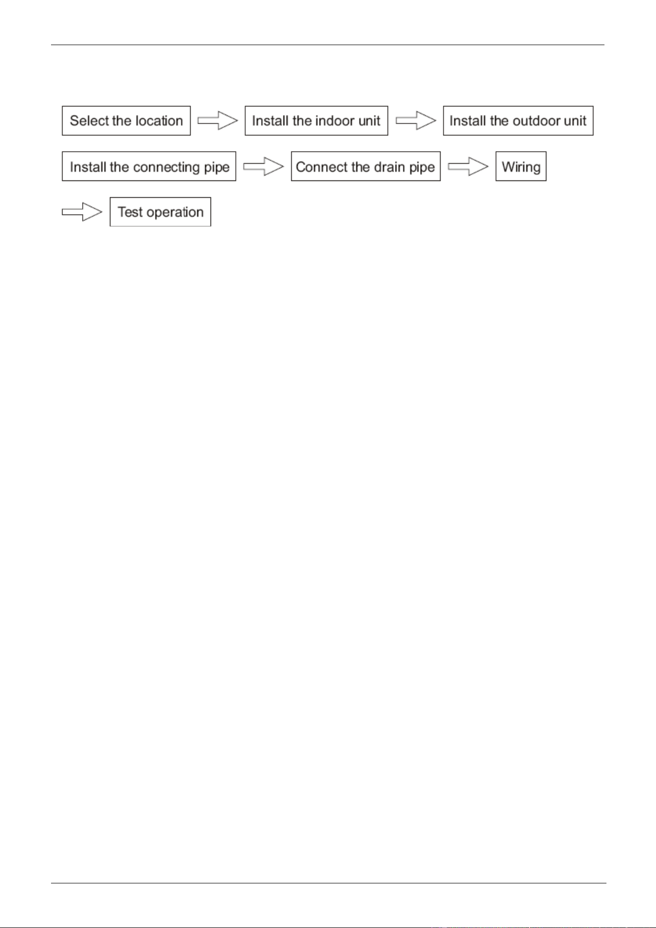
The Installation
1. Before Installation
2. Install the Main Body
3. Installation space
4. Install the Panel
5. Connect the Drain Pipe
6. Wiring
CHIGO CAC FCU MCAC-VTSM-2008-09
Błąd! Nie można odnaleźć źródła odwołania.
1. Before Installation
Please check whether the accessories are of full scope. If there are some fittings free from use, please
restore them carefully.
2. Installation space
(refer to the unit dimension .)
The indoor unit should be installed in a location that meets the following requirements:
There is enough room for installation and maintenance.
The ceiling is horizontal, and its structure can endure the weight of the indoor unit.
The outlet and the inlet are not impeded, and the influence of external air is the least.
The air flow can reach throughout the room.
The connecting water pipe and drainpipe could be extracted out easily.
There is no direct radiation from heaters.
Caution:
Keep indoor unit, outdoor unit, power supply wiring and transmission wiring at least 1 meter away from
televisions and radios. This is to prevent image interference and noise in those electrical appliances. (Noise
may be generated depending on the conditions under which the electric wave is generated, even if 1 meter
is kept.)
CHIGO CAC FCU
3. Install the Main Body
A. Exiting ceiling (Keep the ceiling level)
(1) Drill some holes on the ceiling according to the installation paper card
● Keep the center of the ceiling opening in line with that of the main unit;
● Ensure the length and outward holes of the connecting pipes, drain pipes and electrical connection;
● Please reinforce the strength of the ceiling to keep the ceiling level and without vibration
(2) Determine the location of installation hook according to holes of the installation hook on four corners of
the installation paper card.
● Drill four holes with φ12mm and height of 50~55mm at the position as determined on the roof, and then
lay expansion hooks;
● Aim the concave of the installation hook at the expansion hook when installing. Determine the length of
the hook based on the height of ceiling and then cut away the excessive part;
● If the ceiling is rather high, cut the installation hook at the middle. Use φ12 round steel bar for welding
and the length of the steel bar is based on the height of ceiling
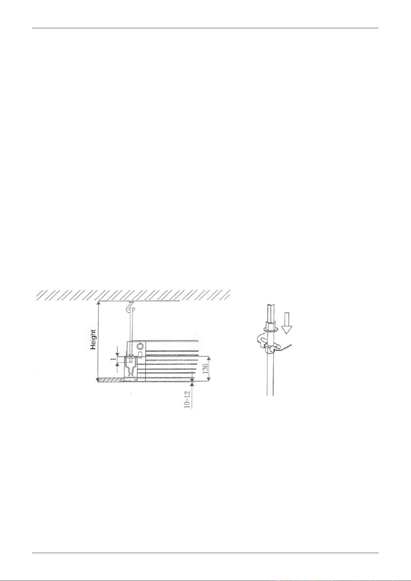
Please adjust the four hexagon nuts on the installation hook and keep the main unit level
● If the drain pipe is slanted, it may cause error action of the water level switch and then water leakage;
● Adjust the location of the main unit to ensure even distance to the four sides of the ceiling and the bottom
of the main unit into the bottom of the ceiling for 10~12mm (See Bottom left figure)
● After adjusting the location and levelness of the main unit, fasten the nuts on the installation hooks to fix
the unit (see bottom right figure)
B. For new room and new ceiling
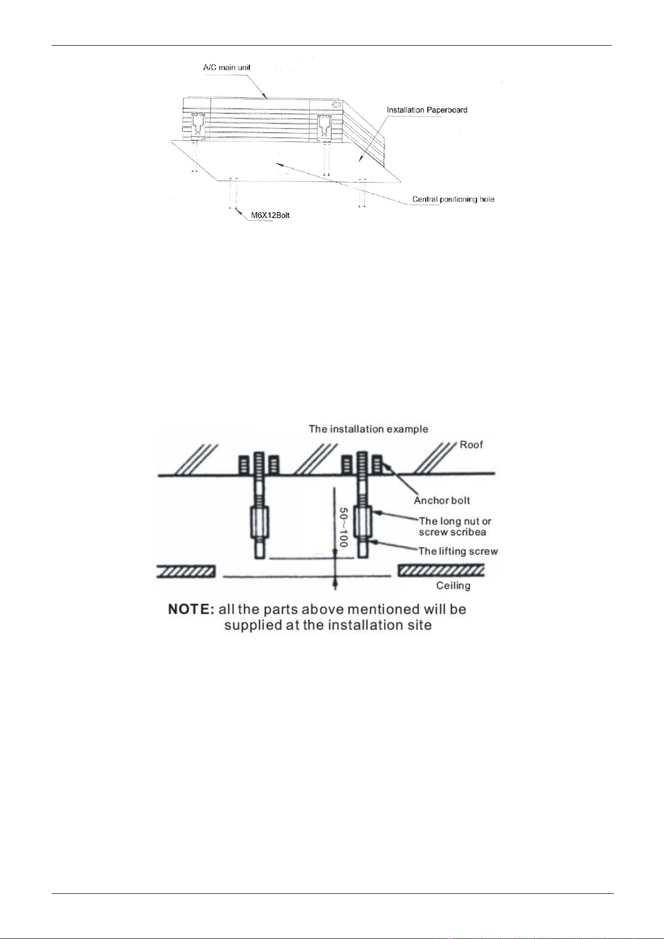
(1) Carry out installation following the step of A (2) aforesaid. You can buried some hooks in new room,
which can bear the weight of the unit and not loose for concrete shrinking;
(2) After hoisting the main unit, fix the installation paperboard onto the main unit with M6 ×12 bolts
(accessories), which will determine the size and position of the ceiling opening (See Fig 7)
● Keep the ceiling level when installing;
● The rest procedure is as the steps of A(1) aforesaid;
(3) Install as the steps of A(3) aforesaid
(4) Remove the installation paperboard
CHIGO CAC FCU MCAC-VTSM-2008-09
Błąd! Nie można odnaleźć źródła odwołania.
Note: After installing the main unit, fix the four bolts M6 ×12 onto the main unit to fasten the unit.
4. Install the Panel
Caution:
Never put the panel face down on floor or against the wall, or on bulgy objects.
Never crash or strike it.
A. Remove air inlet grille
(1) Slide or press down the two grille switches together, and then lift them up (See Fig 8);
(2) Lift the air inlet grille to about 45° and then take it down (See Fig 9);
B. Remove installation lid from four corners
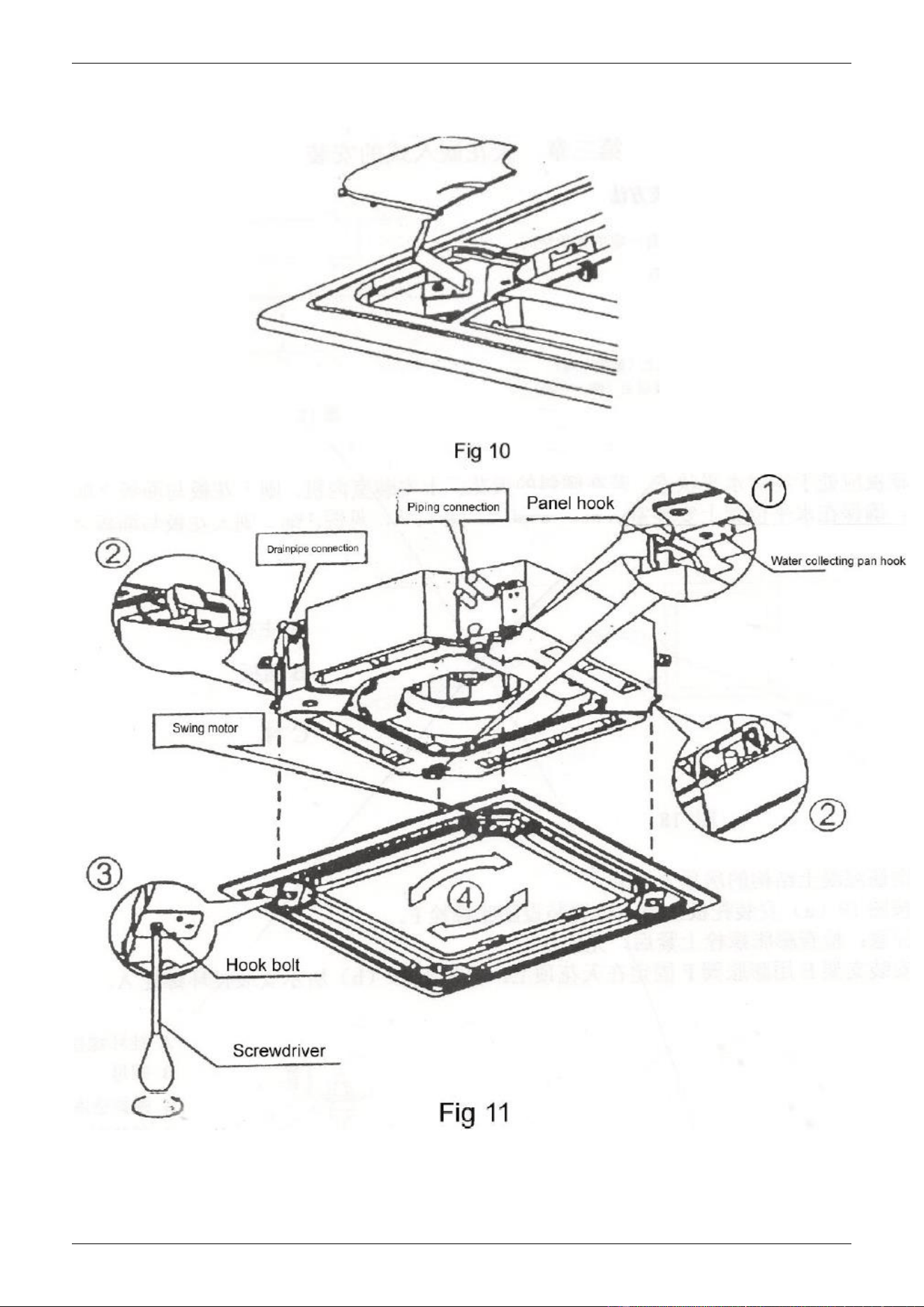
Unscrew the bolts and loosen the rope of installation lid and then draw out the lid (See Fig 10)
C. Install the panel
(1) Point the swing motor on the panel straight to the tubing side of the main unit (See Fig 11);
(2) In installation, put the hooks of swing motor and the panel onto the hook of water pan on the main unit
(as shown in Fig 12①), and then put the rest two hooks of the panel onto the suspending support of the main
unit (as shown in Fig 12②);
NOTE: The summit of the plastic lid of the swing motor should be inserted into the recess of the sealing
panel of the outlet pipe;
(3) Insert the lead of the swing motor into the clip position on the panel;
NOTE: Not entangle the lead into the sealed sponge
(4) Adjust the four hook bolts to keep the panel level and evenly lift t to the position close to the ceiling (as
shown in Fig 11③)
CHIGO CAC FCU
(5) Slightly adjust the panel following the arrow direction (Fig 11④) to keep the center of the panel in line
with that of the ceiling opening. Check whether the hooks on four corners are put up.
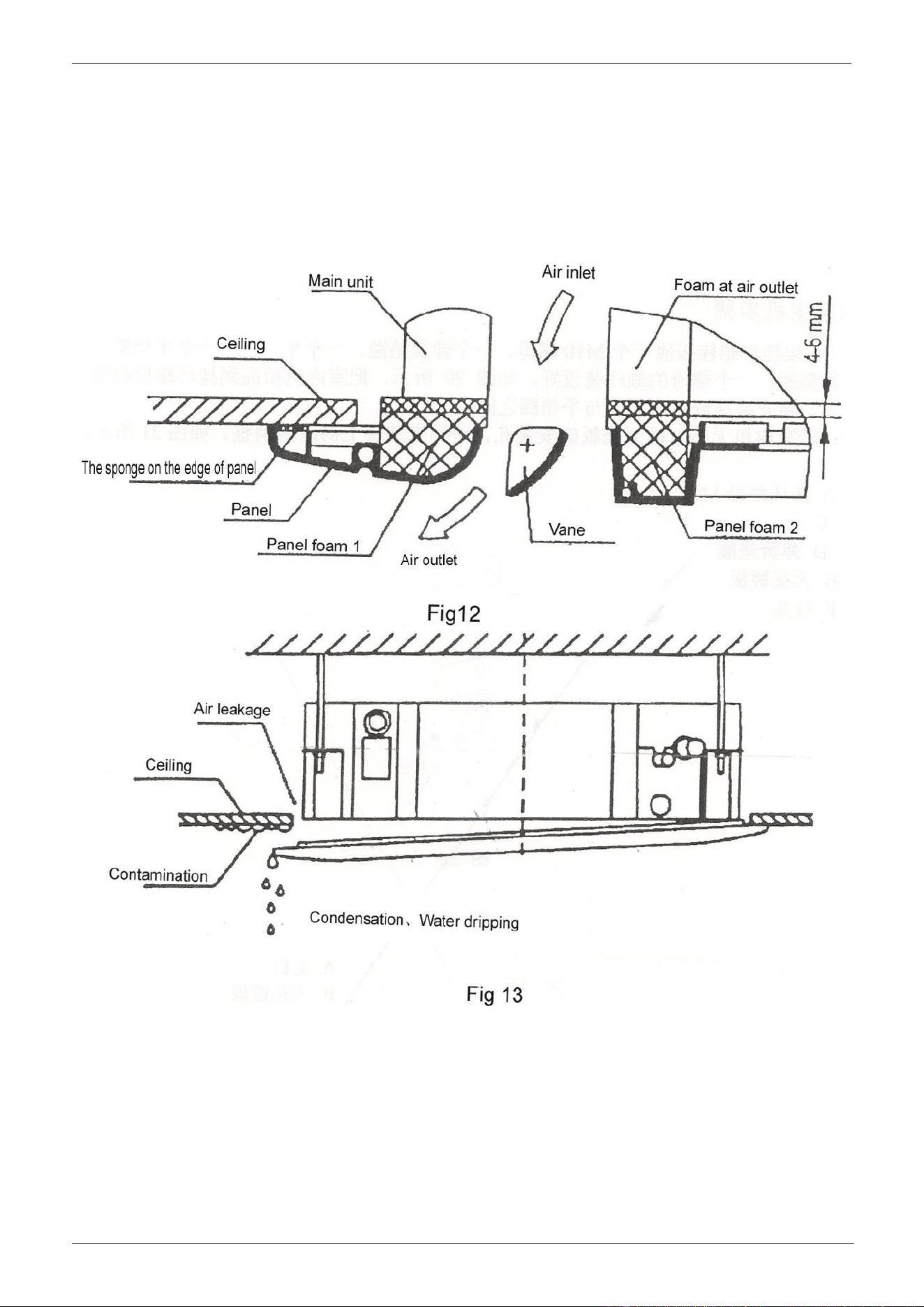
(6) Continue to tighten evenly the bolts under the hooks till the thickness of the sponge between the main
unit and the panel is reduced to 4~6mm,and the edges of the panel are all contact well with the ceiling (See
Fig12)
● Improper tightness of bolts will cause failure shown in Fig 13;
CHIGO CAC FCU MCAC-VTSM-2008-09
Błąd! Nie można odnaleźć źródła odwołania.
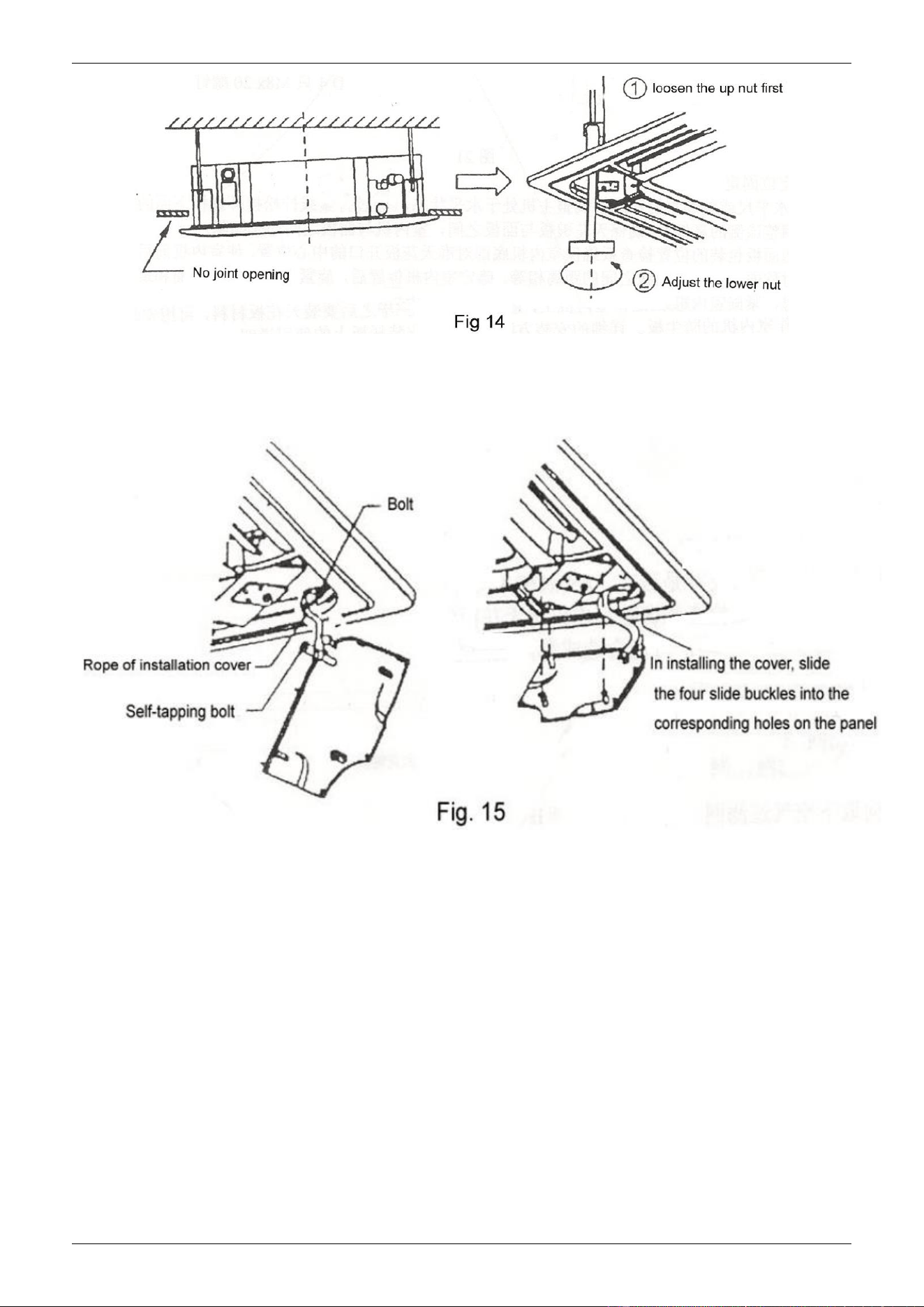
● After tightening bolts, if there is still a slit between the ceiling and the panel, adjust the height of the unit
again (See the left one of Fig 14);
● If lifting and declining the unit and the length of drain pipe is not limited, you can adjust the height of
indoor unit through the opening at the four corners (See the right one of Fig 14)
D. First put the air grille onto the panel and then connect the leads of the swing motor and the control box
with the corresponding connectors on the main unit;
E. Install the air inlet grille contrary to the steps of removing it;
CHIGO CAC FCU
F. Insert the installation cover board again
(1) Fix the rope of the installation cover board at the bolt of the cover board(See the left one of Fig 15);
(2) Slightly push the cover into the panel (see the right one of Fig 15)
CHIGO CAC FCU MCAC-VTSM-2008-09
Błąd! Nie można odnaleźć źródła odwołania.
5. Connect the Drain Pipe
A. Install the drainpipe
(1) Adopting the hard PVC pipe(Outer diameter 37-39mm, Inner diameter 32mm),the proper drainpipe can
be purchased from the distributor or market;
(2) Connect the drainpipe to the bottom of the water suction pipe of the main unit and fasten it together with
the water outlet insulating pipe with the clip of the water outlet pipe.
Note: Be gentle to prevent the water suction pipe from cracking.
(3) The water suction pipe and drainpipe (especially the indoor section) should be bound with the water
outlet insulation sleeve and then fasten it with the band to avoid the entrance of air that will cause
condensation.
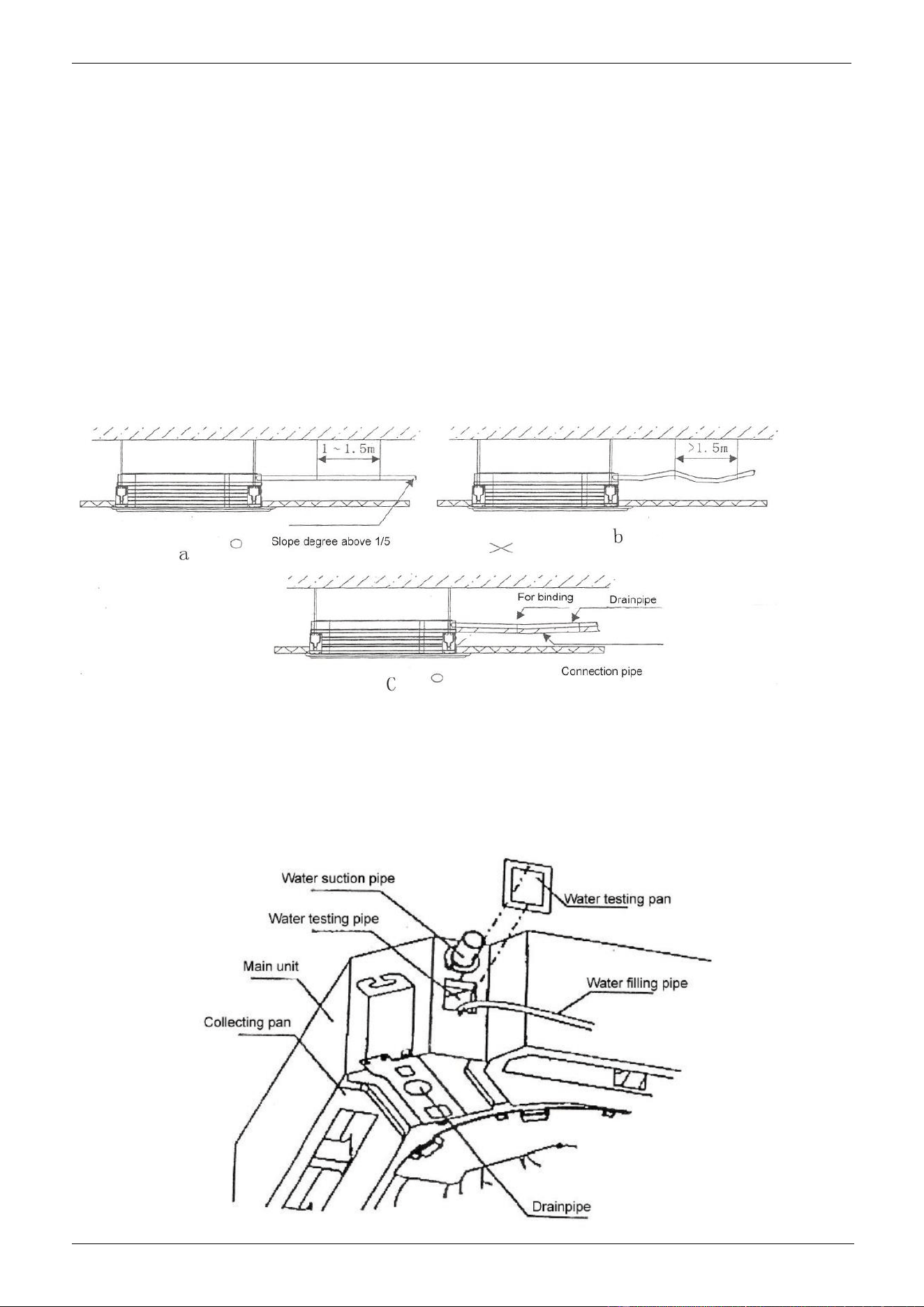
(4) In order to avoid of the backward flow into the air condition when stopping running, incline the drain pipe
toward the outdoor side (drain side ) with the gradient of more than 1/50. Avoid of any protrusion or water
trap (Refer to Fig a)
(5) Not pull the drainpipe when connecting and set a supporting point every1-1.5m to avoid of bending of
the drainpipe( Refer Fig b);Besides, you can wrap the drainpipe and connection pipe together first and then
fix the fronter with the later ( Refer Fig C)
(6) To connect the drainpipe lengthened, wrap the indoor part with protective pipe to keep it from loosing;
(7) If the outlet of the drainpipe is above the water suction pipe of the main unit, keep the drainpipe vertically
upward as much as possible. The bending part of the pipe adopts the rigid pipe with reliable support and
the rise height of the pipe is less than 20mm to avoid of overflowing for the flow back when stopping.
(8) Keep distance of the end of drainpipe and the ground or the bottom of the waterspout more than 50mm
and not extend into water. When draining directly the condense water to waterspout, bend the drainpipe
upward into the “ U” shape to prevent bad smell from entering room.

CHIGO CAC FCU
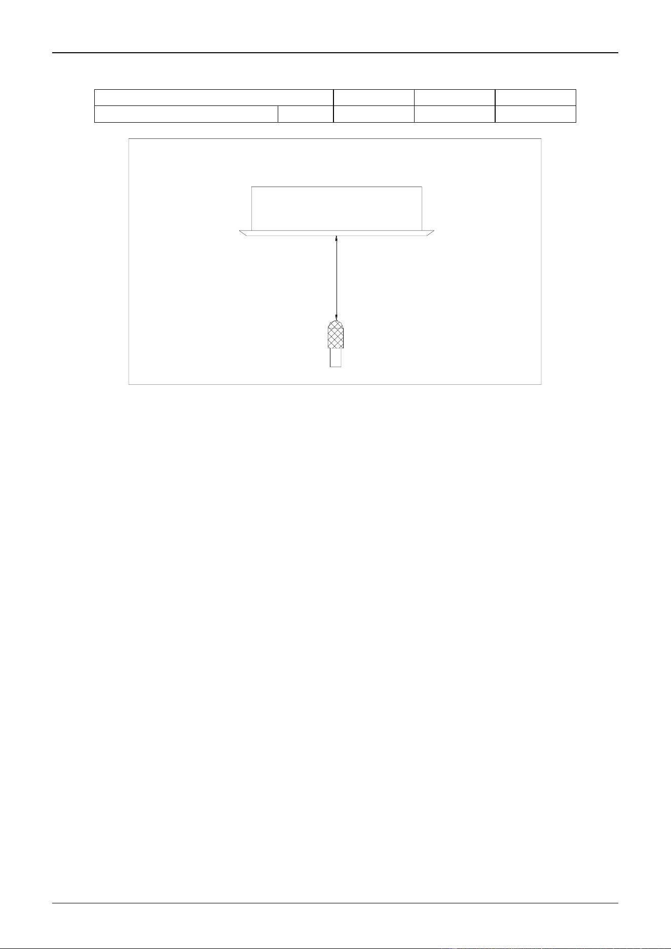
B. Drain test
(1) Check whether the drainpipe is smooth and joints are all sealed well before test;
(2) As for the new room, please do the drain test first, and then lay the ceiling
● Fill 2000 ml water into the water pan with filling pipe at the water testing port (Refer to Fig 17);
● Power on the unit and start the cooling operation to check whether the noise of drain pump and the drain
is normal (Basing on the length of drainpipe, it will delay about 1 minute before draining) and whether there
is water leakage at joints. Remove problems immediately, if any;
● Stop the unit and check if there is any abnormal situation 3 minutes later. In case of irrational layout of
drainpipe, the alarm lamp of the control will flash for the much flow back or the water will flow out from
water pan;
● Cut off the power and empty the seeper, then install back the cover;
(3) The drain plug at the bottom of the main body is used for emptying the water of the water pan in repairing
of problems. When the unit is running , put the plug in position to avoid of water leakage.

CHIGO CAC FCU MCAC-VTSM-2008-09
Błąd! Nie można odnaleźć źródła odwołania.
6. Wiring
Caution:
1. The air conditioner should use separate power supply with rated voltage.
2. The external power supply to the air conditioner should have ground wiring, which is linked to the
ground wiring of the indoor and outdoor unit.
3. The wiring work should be done by qualified persons according to circuit drawing.
4. An all-pole disconnection switch having a contract separation of at least 3mm in a pole should be
connected in fixed wiring.
5. Be sure to locate the power wiring and the signal wiring well to avoid cross-disturbance.
6. Do not turn on the power until you have checked carefully after wiring.
Note:
Remark per EMC Directive 89/336/EEC to prevent flicker impressions during the start of the compressor
(technical process), following installation conditions do apply.
1. The power connection for the air conditioner has to be done at the main power distribution. The
distribution has to be of a low impedance, normally the required impedance reaches at a 32 A fusing
point.
2. No other equipment has to be connected with this power line.
3. For detailed installation acceptance please refer to your power supplier, if restrictions do apply for
products like washing machines, air conditioners or electrical ovens.
4. For power details of the air conditioner refer to the rating plate of the product.
5. For any question contact your local dealer.
CHIGO CAC FCU
Part 4: Controller
Wireless remote controller
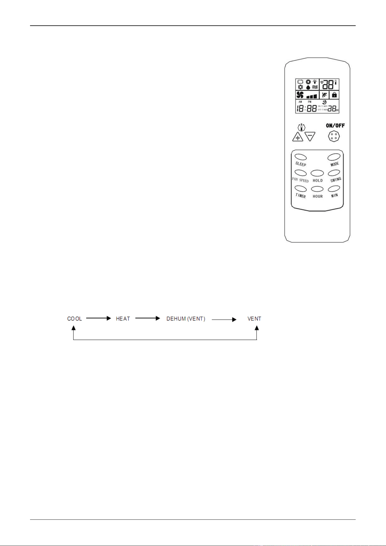
1.Type 1
The operation of the remote controller
● ON/OFF button
For ON/OFF operation of air conditioner. In ON mode, LCD
displays time, operating mode, temperature set , fan speed set and
setting of air vane; In OFF mode, LCD just displays the time.
● TEMP - button
Press this button once to reduce 1℃. In cooling , heating ,
dehumidifying and ventilating mode, the lowest temperature is 18℃.
● TEMP + button
Press this button once to increase 1℃. In cooling , heating ,
dehumidifying and ventilating mode, the highest temperature is 29℃.
● FAN SPEED button
For setting fan speed. Press the button, the speed will be
switched among HIGH, MID, LOW and AUTO. Press it once to switch
once;
● VANE SWING button
For changing the vane swinging mode. Press the button, the vane will swing or stop.
Press this button once to switch the vane once.
● MODE button
For setting operating mode. Press this key, the mode will be changed and the order is
as follow:
● SLEEP button
For setting SLEEP state or exiting the SLEEP state.
● LOCK/UNLOCK button
For setting locking function. Press this button to lock or unlock the controller.
● TIMING button
For setting timing mode. Press this key to select timing ON or timing OFF.
CHIGO CAC FCU
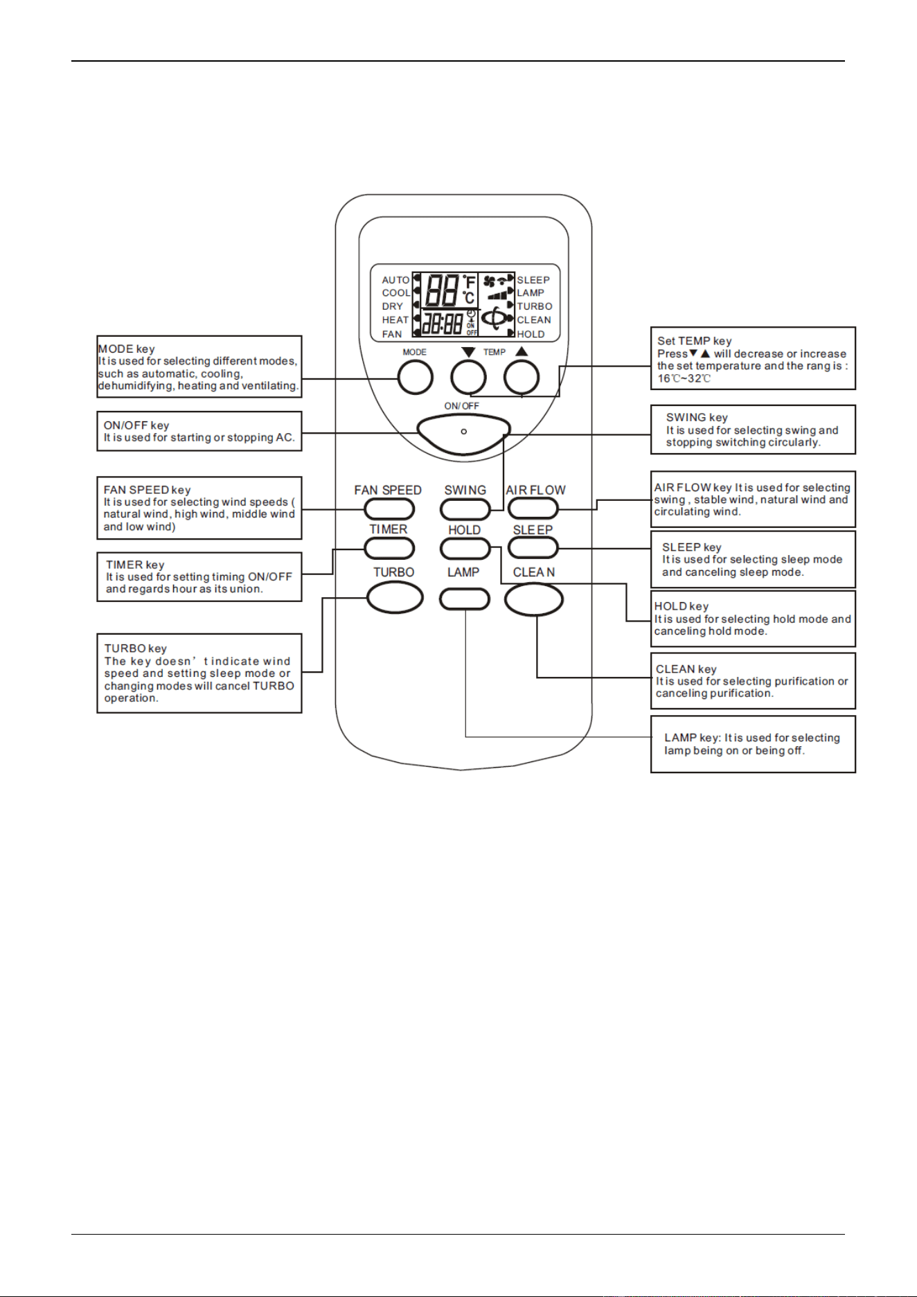
2. Type 2
` The model of the following remote controller is Lingtong common remote controller.
TURBO key, LAMP key, AIR FLOW key and CLEAN key is applicable for special latest
developed new models instead of normal ones.
2.1 Introduction of Functional Key
■ ON/OFF key: Press the key and the remote control will switch circularly in the order : ON→
OFF→ON.
When it is powered on at first from off state to on state, the default setting of work
condition is ( The set temperature is 25℃ and the mode , wind speed, swing and air door are
all automatic and there is no LAMP, no TURBO, no CLEAN, no SLEEP, no TIMER and no
HOLD function ). When it is not powered on firstly from OFF state, the work condition is as the
same as the state before stopping. It will cancel LAMP, CLEAN, SLEEP, TURBO and TIME
mode.
■ MODE key: Press the key to switch modes in the order :AUTO→COOL→DRY→HEAT→FAN→
AUTO
■ ▼ key: In DRY mode or AUTO mode, pressing▼key cannot change the temperature. In
other mode, press the key once and the temperature will decrease 1℃ in the order : 32℃→
31℃→…→17℃→16℃ .

CHIGO CAC FCU
■ ▼key:In DRY mode and AUTO mode, pressing ▼ key cannot change the temperature. In
other mode, press the key once and the temperature will increase 1℃ in the order: 16℃→17℃
→…→31℃→32℃ .
■ FAN SPEED key: The default wind speed is in the automatic wind mode when
starting firstly. The remote control won’t react by pressing the key because
the wind speed can’t be adjusted and in low speed in dehumidifying mode. In
other mode, press the key to switch modes in the order : automatic wind→ high
speed →middle speed→ low speed →automatic wind.
■ SWING key : In dehumidifying mode, the swing mode is in the stable wind
mode without change. In other mode, press the key to switch modes in the
order: swing →stable wind→natural wind →swing.
■ AIR FLOW key : The default air flow is in the swing mode when starting firstly
and press the key to switch modes in the order: SWING →STOP →SWING.
■ TIMER key : The default mode is in no timing state, press the key to set timing
time . The switch order is: 1H→2H→…→24H→cancel→1H…. Press the key
to set timing starting in the OFF state and set timing stopping in the ON state.
After setting timing function, the time keeps decreasing per hour until the
time decreasing to the timing on or timing off and the timing display will be
cancelled at the same time . Pressing MODE key can’t cancel timing in
timing mode which will set out timing time by pressing other key.
■ HOLD key: The default state is in no HOLD key state, press the key to select
modes in order: HOLD key →cancel HOLD key→ HOLD key ; In HOLD key
mode, all keys except HOLD key of the remote control can’t work .
( NOTE: In HOLD key mode, the remote and operation panel of the unit both
will be locked automatically by pressing the key and press the key again , they
will be unlocked. As for the split unit , it only hold the control other than
EMERGENCY key and the panel will make a reaction.)
■ SLEEP key : Press the key to switch modes in the order: SLEEP→ cancel
SLEEP→ SLEEP. The sleeping function won’t be cancelled for changing
modes. Press the key to set sleep mode and the wind speed will automatically
be switched to low speed and it can adjust the wind speed by pressing the
FAN SPEED key (except dehumidifying mode).
■ TURBO key: The default state for the control is no turbo and the key don’t
work in the AUTOMATIC mode, DRY mode and FAN mode ( It will not display
any contents and not send out any codes). The control, however, will switch
between on and off by pressing the key in other mode. The wind speed isn’t
indicated in turbo mode and it will be cancelled for changing modes and
setting sleep mode.
■ LAMP key : The default state is in no LAMP key state, press the key to select
modes in order : LAMP key →cancel LAMP key→ LAMP key; In LAMP key
mode, pressing MODE key can’t cancel the show of LAMP key.
■ CLEAN key : The default state is in no purification state, press the key to select
modes in order : CLEAN →cancel CLEAN→ CLEAN; In CLEAN mode,

CHIGO CAC FCU
pressing CLEAN key can’t cancel CLEAN function. Press the key when
the remote control is closed, the control will switch modes in the order :
CLEAN →cancel CLEAN→ CLEAN; When you stop the unit and turn on the
purification switch, except the wind, the stable swing and air door swing speed
aren’t adjusted.