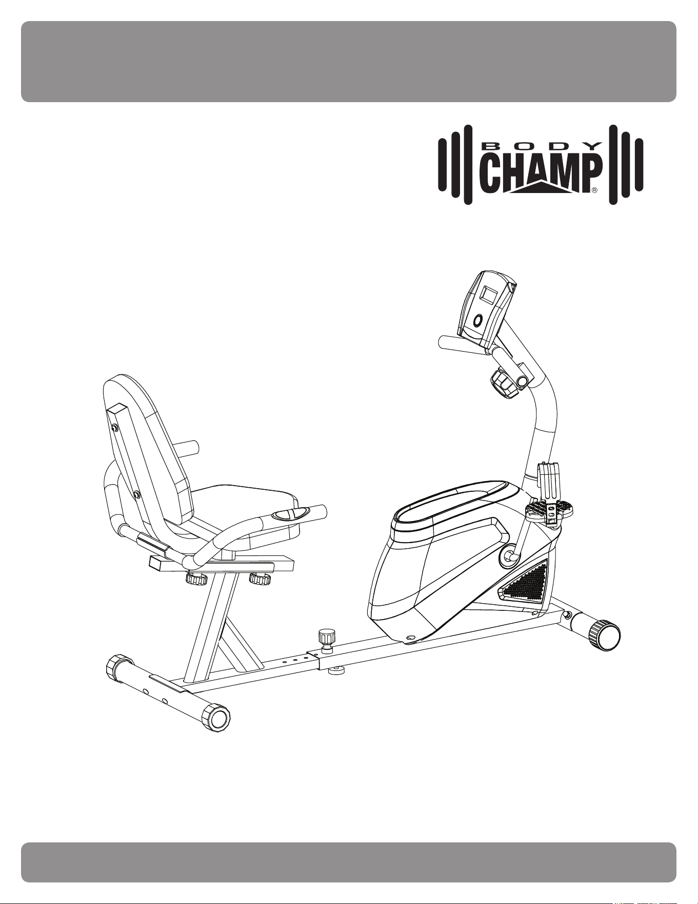
BRM2720X BRM2780
Cardio Dual Trainer
This product is intended for indoor, home use only and is not to be used in a commercial setting.
OWNER’S MANUAL

BRM2720X BRM2780
Cardio Dual Trainer
This product is intended for indoor, home use only and is not to be used in a commercial setting.
OWNER’S MANUAL
BRM2720X / 2780 Page
1
PLEASE KEEP THESE INSTRUCTIONS FOR FUTURE USE & REFERENCE.
DO NOT DISCARD.
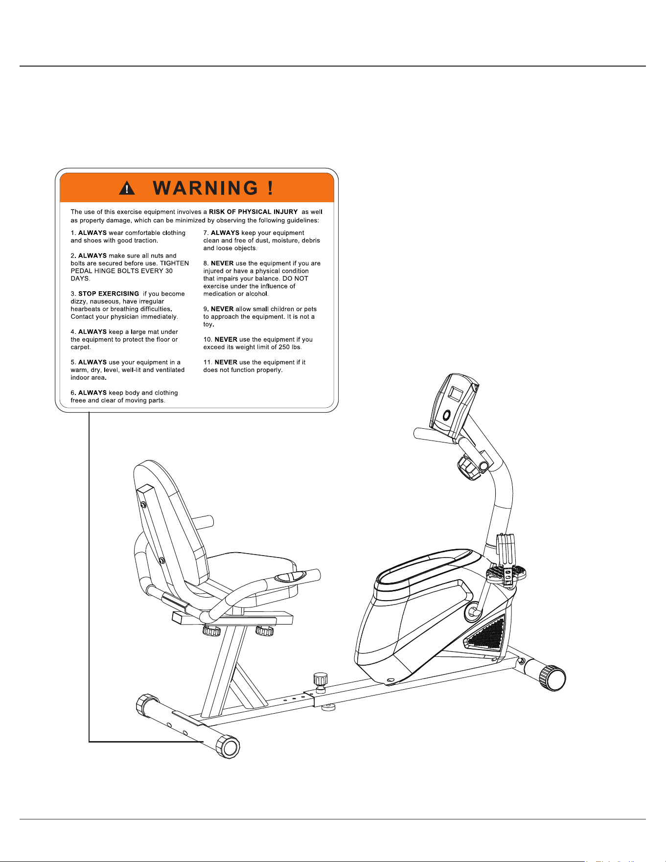
WARNING: SERIOUS INJURIES AND EVEN DEATH CAN OCCUR IF THE PROPER SAFETY PRECAUTIONS
ARE NOT FOLLOWED.
The diagram below highlights and reviews many of the important Safety and Warning labels also found on the unit.
Please ensure any user of the unit familiarizes themselves with these Safety and Warning guidelines before use.

BRM2720X / 2780 Page
1
PLEASE KEEP THESE INSTRUCTIONS FOR FUTURE USE & REFERENCE.
DO NOT DISCARD.
WARNING: SERIOUS INJURIES AND EVEN DEATH CAN OCCUR IF THE PROPER SAFETY PRECAUTIONS
ARE NOT FOLLOWED.
The diagram below highlights and reviews many of the important Safety and Warning labels also found on the unit.
Please ensure any user of the unit familiarizes themselves with these Safety and Warning guidelines before use.
BRM2720X / 2780 Page
2
Before you undertake any exercise program, please be sure to
consult with your doctor.
Frequent strenuous exercise should be approved by your
doctor and proper use of your product is essential.
Excessive or incorrect training may result to health injuries.
Please read this manual carefully before commencing the
assembly of your product or starting to exercise.
• Please keep all children away from this item when in use.
Do not allow children to climb or play on this item when it
is not in use.
• Supervise teenagers while they use this unit.
• For your own safety, always ensure that there is at least
3 feet of free space in all directions around your product
while you are exercising.
• Regularly check to see that all nuts, bolts and ttings are
securely tightened. Periodically check all moving parts for
obvious signs of wear or damage.
• Any adjustment devices that could interfere with the user’s
movement on this unit should not be left projecting.
• Clean only with a damp cloth, do not use solvent
cleaners. Lubricate the moving parts of your unit every 30
days with a silicone-based grease or product.
If you are in any doubt, do not use your product; contact
CUSTOMER SUPPORT.
• Before use, always ensure that your product is positioned
on a solid, hard-at surface.
• Do not place on carpet. If necessary, use a rubber mat
underneath to reduce the possibility of slipping.
• Always wear appropriate clothing and footwear such as
training shoes when exercising. Do not wear loose clothing
that could become caught in moving parts during exercise.
• Do not use this unit if it is not functioning properly or if it is
not fully assembled.
• Do not use this unit for commercial purposes. This unit is
for home use only.
• Before use, you must read and understand all instructions
& warnings stated in this Owner’s Manual as well as
posted on the equipment.
• It is the facility owner’s responsibility to properly instruct
users on the proper operation of the equipment and to
warn them of the potential hazards.
• If at any time during exercise you feel faint, dizzy or
experience pain, stop and consult your physician.
Your product is intended for use in clean dry conditions. You
should avoid storage in excessively cold or damp places as
this may lead to corrosion and other related problems.
If you have any questions concerning the assembly of your
item or if any parts are missing, please DO NOT RETURN
THE ITEM TO THE STORE OR CONTACT THE
RETAILER.
Our dedicated customer service sta can help you with
any questions you may have regarding the assembly of this
unit and can also mail you replacement parts.
Customer Support is open 9:00 a.m. to 5:00 p.m. (Pacic
Time) Monday through Friday.
Please contact us by any of the following means :
Body Flex Sports, Inc.
21717 Ferrero Parkway, Walnut, CA 91789
Telephone: 1 (888) 266A - 6789
Fax: 1 (909) 598 - 6707
Email: info@bodyexsports.com
Body Flex Sports warrants your product for a period of
1 year for the frame and 90 days on all parts if the item is used
for the intended purpose, properly maintained and not used
commercially.
Any alterations or incorrect assembly of the product will void
this warranty.
Proof of purchase must be presented for any warranty
validation (no exceptions). This warranty applies to the original
purchaser only and is not transferable.
This warranty does not cover abuse or defects caused during
use, storage or assembly. During the warranty period, Body
Flex Sports reserves the right to:
1. provide replacement parts to the purchaser in an eort to
repair the item.
2. repair the product returned to our warehouse (at the
purchaser’s cost).
3. replace the product if neither of the two previously
mentioned actions eect repair. This warranty does not
cover normal wear and tear on upholstery.
- Ruler with both Metric and English measurements
- 2 x Adjustable Wrenches
- 1 x Philips (”Crosshead”) Screw Driver
Your product is suitable for users weighing :
250 pounds or less
General Information
Safety Storage and Use
Questions
Customer Support
Warranty
Assembling Tools
Weight Limit
BRM2720X / 2780 Page
3
Before Assembly
1. Take a few minutes to familiarize yourself with the parts and hardware included with your product.
2. Assembly may require two people.
3. Check the frame for any damage and check any wiring (if present) for rips or tears. If you detect damage, rips, or
tears, please contact our Customer Support Team before beginning any assembly.
4. Make sure all the hardware needed is included.
5. It is very important to follow the assembly instructions correctly and to make sure all parts are attached correctly and
rmly tightened when the assembly process is complete.
6. Parts that are not tightened correctly will seem loose and can cause irritating noises and will cause damage to the
equipment.
1. It is only necessary to tighten the bolts and nuts to “nger tight” during the assembly process. This will make it
easier to complete certain steps by allowing more tolerance for all the parts to t properly.
2. Do not tighten all the nuts onto the bolts securely until after you have completed assembly of your product.
3. Use wrenches, pliers, or ratchet and sockets to tighten the bolts and nuts.
4. The Nylon Nut should thread onto the Hex Bolt until the end of the Hex Bolt has passed through the Nylon insert
inside the Nut. Please follow this guideline everytime you see this Nylon Nut icon throughout the assembly steps.
Nylon Lock Safety Nuts
Tools Required For Assembly
WARNING
PLEASE NOTE : Many of the parts and hardwares listed on the parts list are already pre-assembled or
installed on the unit.
Tool Description/Purpose
Ruler (with both Metric and English measurements)
QTY: 1
Use to measure the length or size of hardware including
bolts to ensure you are using the correct part.
Adjustable or at wrenches
QTY: 2
Use to securely install parts including nuts and bolts.
BRM2720X / 2780 Page
4
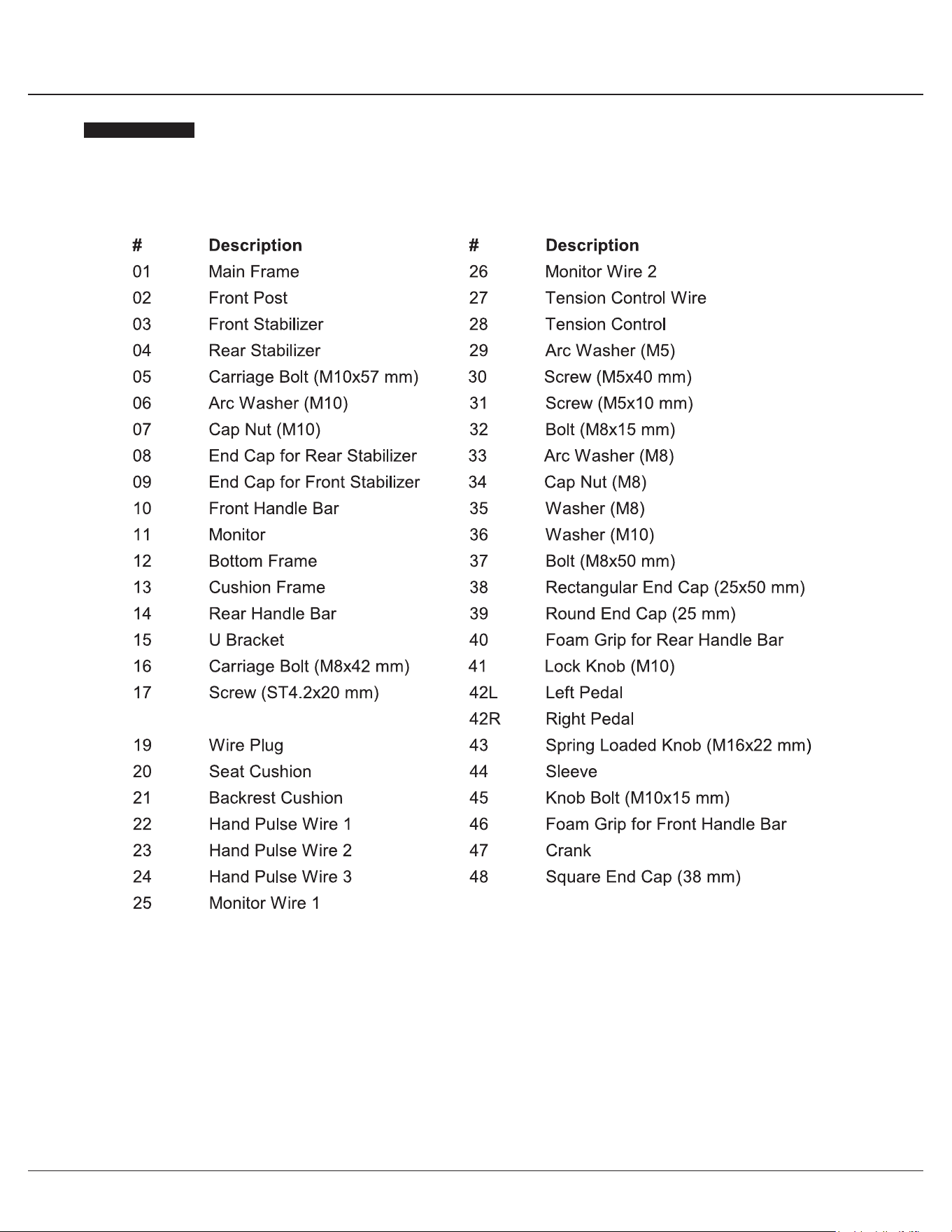
Part Listing
The following parts list describes all of the parts illustrated on the exploded diagram on the following page.
PLEASE NOTE : most of these parts are already pre-assembled on your unit.
# Description
01A Main Frame
02A Center Post
03A Left Pedal Tube
04A Right Pedal Tube
05A Left Coupler Bar
06A Right Coupler Bar
07 Handle Bar
08 Front Stabilizer
09 Rear Stabilizer
10 Seat Post
11 Horizontal Seat Bar
12 Pedal Connection Joint
13A Pulse Handle Bar
14 Crank
16 Knob Bolt
17 Tension Controller
18 Tension Wire
19A Metal Bushing
21 Bolt (1/2"x97 mm)
22 Carriage Bolt (M8x65 mm)
23A Carriage Bolt (M6x38 mm)
24A Bolt (M10x58 mm)
25A Hex Bolt (M8x45 mm)
26 Bolt (M8x15 mm)
27 Bolt (M8x20 mm)
28A Hex Bolt (M8x40 mm)
29 Screw (M5x45 mm)
30 Screw (M5x12 mm)
31 Screw (M4x25 mm)
32 Nylon Nut (1/2")
33 Cap Nut (M8)
34 Nylon Nut (M10)
35 Nylon Nut (M8)
37 Special Washer (16 mm)
# Description
38 Special Washer (19 mm)
39 Spring Washer (M8)
68 Spring Washer (M6)
40 Arc Washer (M8)
69 Arc Washer (M6)
41 Washer (M10)
42 Washer (M8)
44 Washer (M5)
45 D Shape Washer
46 Left Pedal
47 Right Pedal
48 End Cap for Front Stabilizer
49 End Cap for Rear Stabilizer
50A Rectangular Inner Plug (25x50 mm)
51 Round Open End Plug (50x38 mm)
52 Square Open End Plug (45x38 mm)
53 Square Open Plug (38 mm)
54 Plastic Bushing
55 Plastic Bushing
56 Plastic Bushing
57 Round Cap
58 Round Cap
59 Round Inner Cap
60 Pulse Sensor Wire
61 Monitor
62 Monitor Wire (Upper)
63 Monitor Wire (Lower)
64A Handle Bar Foam Grip
65A Pulse Handle Bar Foam Grip
66A Seat
67 Cap Nut (M6)
70 Tool 1
71 Tool 2
72 Bolt (M8x30 mm)
73 Rectangular Inner Plug (25x40 mm)
BRM2720X / 2780 Page
4
Part Listing
The following parts list describes all of the parts illustrated on the exploded diagram on the following page.
PLEASE NOTE : most of these parts are already pre-assembled on your unit.
# Description
01A Main Frame
02A Center Post
03A Left Pedal Tube
04A Right Pedal Tube
05A Left Coupler Bar
06A Right Coupler Bar
07 Handle Bar
08 Front Stabilizer
09 Rear Stabilizer
10 Seat Post
11 Horizontal Seat Bar
12 Pedal Connection Joint
13A Pulse Handle Bar
14 Crank
16 Knob Bolt
17 Tension Controller
18 Tension Wire
19A Metal Bushing
21 Bolt (1/2"x97 mm)
22 Carriage Bolt (M8x65 mm)
23A Carriage Bolt (M6x38 mm)
24A Bolt (M10x58 mm)
25A Hex Bolt (M8x45 mm)
26 Bolt (M8x15 mm)
27 Bolt (M8x20 mm)
28A Hex Bolt (M8x40 mm)
29 Screw (M5x45 mm)
30 Screw (M5x12 mm)
31 Screw (M4x25 mm)
32 Nylon Nut (1/2")
33 Cap Nut (M8)
34 Nylon Nut (M10)
35 Nylon Nut (M8)
37 Special Washer (16 mm)
# Description
38 Special Washer (19 mm)
39 Spring Washer (M8)
68 Spring Washer (M6)
40 Arc Washer (M8)
69 Arc Washer (M6)
41 Washer (M10)
42 Washer (M8)
44 Washer (M5)
45 D Shape Washer
46 Left Pedal
47 Right Pedal
48 End Cap for Front Stabilizer
49 End Cap for Rear Stabilizer
50A Rectangular Inner Plug (25x50 mm)
51 Round Open End Plug (50x38 mm)
52 Square Open End Plug (45x38 mm)
53 Square Open Plug (38 mm)
54 Plastic Bushing
55 Plastic Bushing
56 Plastic Bushing
57 Round Cap
58 Round Cap
59 Round Inner Cap
60 Pulse Sensor Wire
61 Monitor
62 Monitor Wire (Upper)
63 Monitor Wire (Lower)
64A Handle Bar Foam Grip
65A Pulse Handle Bar Foam Grip
66A Seat
67 Cap Nut (M6)
70 Tool 1
71 Tool 2
72 Bolt (M8x30 mm)
73 Rectangular Inner Plug (25x40 mm)
BRM2720X / 2780 Page
5
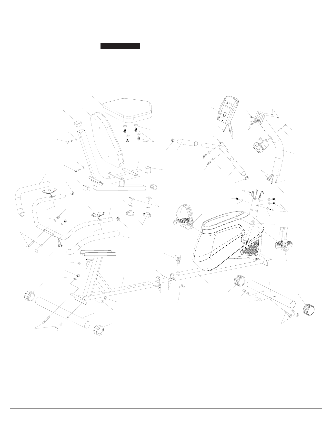
Exploded View
The following diagram is provided to help you familiarize yourself with the parts and hardware that will be used during the
assembly process.
: : Not all of the parts and hardware you see here will be used while you are assembling the machine
because some of these items are already pre-installed. Please use this page only as a reference guide for parts and
hardware.
PLEASE NOTE
BRM2720X / 2780 Page
5
Exploded View
The following diagram is provided to help you familiarize yourself with the parts and hardware that will be used during the
assembly process.
: : Not all of the parts and hardware you see here will be used while you are assembling the machine
because some of these items are already pre-installed. Please use this page only as a reference guide for parts and
hardware.
PLEASE NOTE
BRM2720X / 2780 Page
6
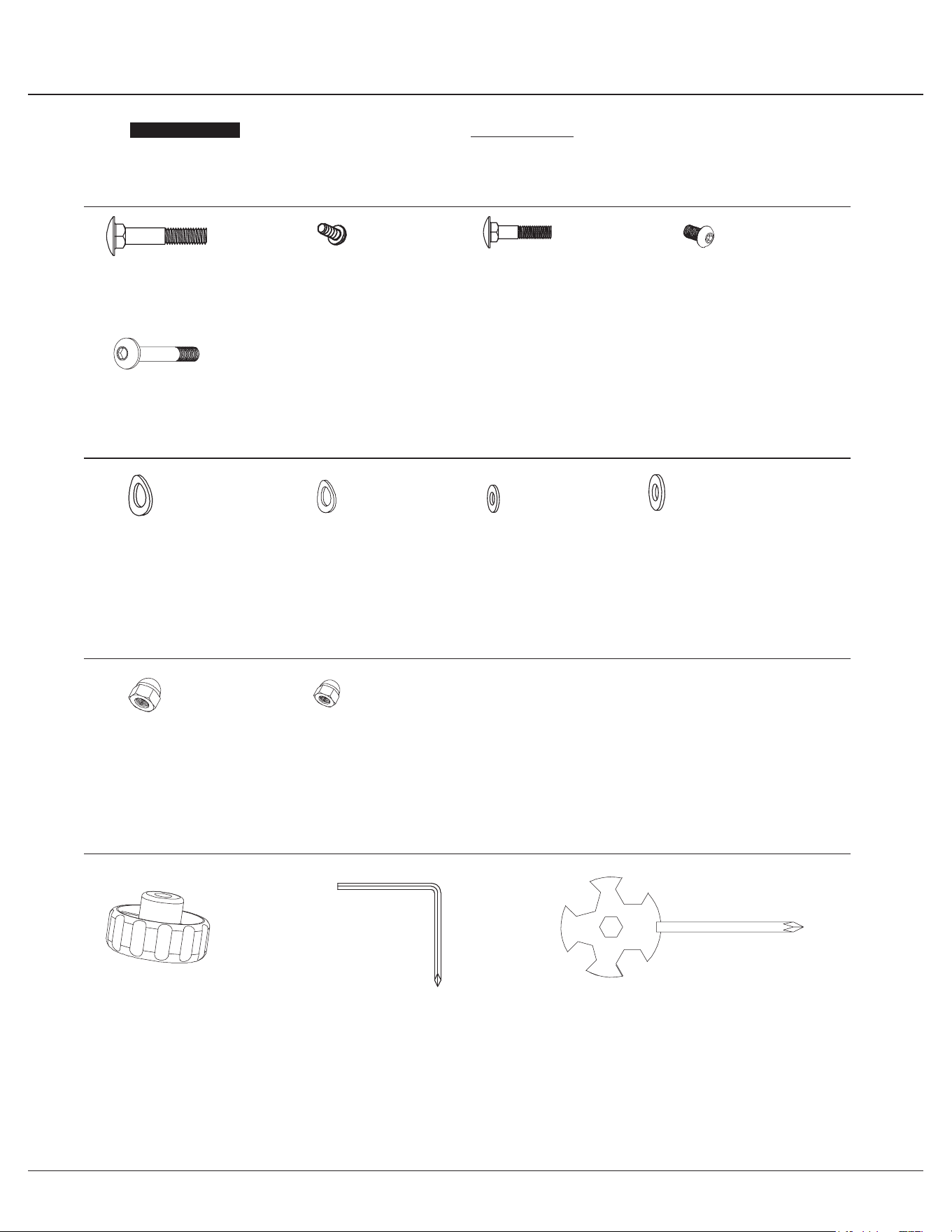
Hardware and Tool List
Bolts
Nuts
Washers
Others
The following hardware is used to assemble your unit. Please take a moment to familiarize yourself with these items.
PLEASE NOTE : Most of these parts are already pre-assembled on your unit. Do not be alarmed if you see parts on this
page that are not included in your hardware packet.
(#21) Bolt (1/2"x97 mm)
[2 Pieces]
(#72) Bolt (M8x30 mm)
[2 Pieces]
(#22) Carriage Bolt (M8x65 mm)
[4 Pieces]
(#24A) Bolt (M10x58 mm)
[2 Pieces]
(#23A) Carriage Bolt (M6x38 mm)
[4 Pieces]
(#28A) Hex Bolt (M8x40 mm)
[6 Pieces]
(#30) Screw (M5x12 mm)
[4 Pieces] pre-assembled
(#33) Cap Nut (M8)
[4 Pieces]
(#32) Nylon Nut (1/2")
[2 Pieces]
(#34) Nylon Nut (M10)
[2 Pieces]
(#35) Nylon Nut (M8)
[9 Pieces]
[3 Pieces] pre-assembled
(#67) Cap Nut (M6)
[4 Pieces]
(#38) Special Washer
(19 mm)
[2 Pieces]
(#37) Special Washer
(16 mm)
[2 Pieces]
(#39) Spring Washer (M8)
[12 Pieces]
[8 Pieces] pre-assembled
(#68) Spring Washer
(M6)
[4 Pieces]
(#40) Arc Washer (M8)
[12 Pieces]
[8 Pieces] pre-assembled
(#69) Arc Washer
(M6)
[4 Pieces]
(#41) Washer
(M10)
[2 Pieces]
(#42) Washer (M8)
[11 Pieces]
[3 Pieces] pre-assembled
(#45) D Shape Washer
[2 Pieces]
(#55) Plastic Bushing
[2 Pieces]
(#57) Round Cap
[2 Pieces]
(#71) Tool 2
[1 Piece]
(#70) Tool 1
[1 Piece]
(#27) Bolt (M8x20 mm)
[2 Pieces]
(#26) Bolt (M8x15mm)
[8 Pieces] pre-assembled
BRM2720X / 2780 Page
6
Hardware and Tool List
Bolts
Nuts
Washers
Others
The following hardware is used to assemble your unit. Please take a moment to familiarize yourself with these items.
PLEASE NOTE : Most of these parts are already pre-assembled on your unit. Do not be alarmed if you see parts on this
page that are not included in your hardware packet.
(#21) Bolt (1/2"x97 mm)
[2 Pieces]
(#72) Bolt (M8x30 mm)
[2 Pieces]
(#22) Carriage Bolt (M8x65 mm)
[4 Pieces]
(#24A) Bolt (M10x58 mm)
[2 Pieces]
(#23A) Carriage Bolt (M6x38 mm)
[4 Pieces]
(#28A) Hex Bolt (M8x40 mm)
[6 Pieces]
(#30) Screw (M5x12 mm)
[4 Pieces] pre-assembled
(#33) Cap Nut (M8)
[4 Pieces]
(#32) Nylon Nut (1/2")
[2 Pieces]
(#34) Nylon Nut (M10)
[2 Pieces]
(#35) Nylon Nut (M8)
[9 Pieces]
[3 Pieces] pre-assembled
(#67) Cap Nut (M6)
[4 Pieces]
(#38) Special Washer
(19 mm)
[2 Pieces]
(#37) Special Washer
(16 mm)
[2 Pieces]
(#39) Spring Washer (M8)
[12 Pieces]
[8 Pieces] pre-assembled
(#68) Spring Washer
(M6)
[4 Pieces]
(#40) Arc Washer (M8)
[12 Pieces]
[8 Pieces] pre-assembled
(#69) Arc Washer
(M6)
[4 Pieces]
(#41) Washer
(M10)
[2 Pieces]
(#42) Washer (M8)
[11 Pieces]
[3 Pieces] pre-assembled
(#45) D Shape Washer
[2 Pieces]
(#55) Plastic Bushing
[2 Pieces]
(#57) Round Cap
[2 Pieces]
(#71) Tool 2
[1 Piece]
(#70) Tool 1
[1 Piece]
(#27) Bolt (M8x20 mm)
[2 Pieces]
(#26) Bolt (M8x15mm)
[8 Pieces] pre-assembled

BRM2720X / 2780 Page
7
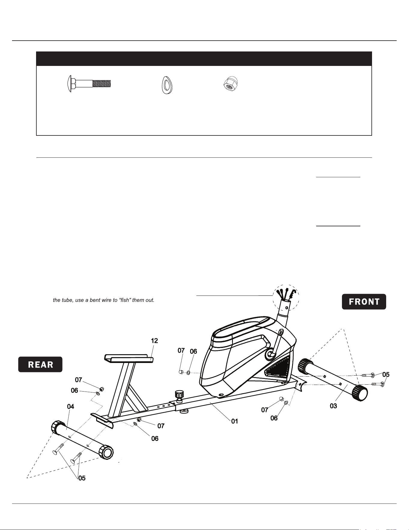
Assembly STEP 1
With the help of an assistant, attach the Front Stabilizer (#08)
to the front of the Main Frame (#01A). Insert two Carriage Bolts
(#22) through the Front Stabilizer (#08) followed by the front of the
Main Frame (#01A). Secure them together using two Arc Washers
(#40), two Spring Washers (#39) and two Cap Nuts (#33).
Now attach the Rear Stabilizer (#09) to the rear of the Main
Frame (#01A) . Insert two Carriage Bolts (#22)
through the Rear
Stabilizer (#09) followed by the rear of the Main Frame (#01A).
Secure them together using two Arc Washers (#40), two Spring
Washers (#39) and two Cap Nuts (#33).
Please Note that the Front Stabilizer (#08) has end caps that
spin for ease of relocating the unit and the Rear Stabilizer
(#09)
has height adjustable end caps for leveling of the unit.
Hardware Required
#22 Carriage Bolt (M8x65 mm )
[4 Pieces]
#40 Arc Washer (M8)
[4 Pieces]
Front Roller
#39 Spring Washer (M8)
[4 Pieces]
#33 Cap Nut (M8)
[4 Pieces]

BRM2720X / 2780 Page
7
Assembly STEP 1
With the help of an assistant, attach the Front Stabilizer (#08)
to the front of the Main Frame (#01A). Insert two Carriage Bolts
(#22) through the Front Stabilizer (#08) followed by the front of the
Main Frame (#01A). Secure them together using two Arc Washers
(#40), two Spring Washers (#39) and two Cap Nuts (#33).
Now attach the Rear Stabilizer (#09) to the rear of the Main
Frame (#01A) . Insert two Carriage Bolts (#22)
through the Rear
Stabilizer (#09) followed by the rear of the Main Frame (#01A).
Secure them together using two Arc Washers (#40), two Spring
Washers (#39) and two Cap Nuts (#33).
Please Note that the Front Stabilizer (#08) has end caps that
spin for ease of relocating the unit and the Rear Stabilizer
(#09)
has height adjustable end caps for leveling of the unit.
Hardware Required
#22 Carriage Bolt (M8x65 mm )
[4 Pieces]
#40 Arc Washer (M8)
[4 Pieces]
Front Roller
#39 Spring Washer (M8)
[4 Pieces]
#33 Cap Nut (M8)
[4 Pieces]
BRM2720X / 2780 Page
8
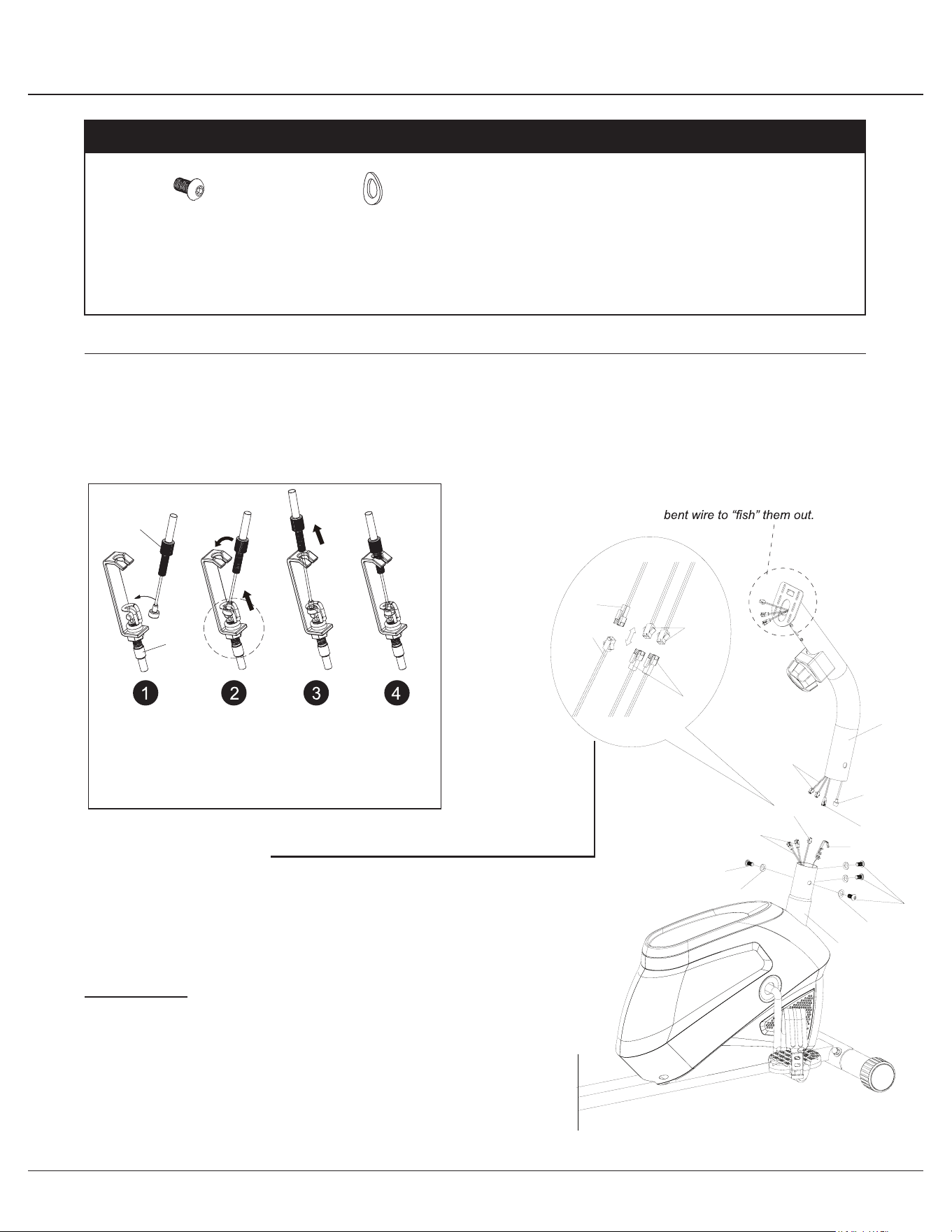
Assembly STEP 2
Remove the Bolts (#26), Spring Washers (#39), and Arc
Washers (#40) that are pre-assembled on the Main Frame (#01A)
and set them aside as they will be used later in this step.
Connect the Monitor Wire (Upper) (#62) to the Monitor
Wire (Lower) (#63) and then follow the instructions in the
diagram below to connect the Tension Wire (#18).
After connecting the Tension Wire (#18) to the Tension
Controller (#17) slide the Center Post (#02A) onto the Main
Frame (#01A) and secure it using the Bolts (#26), Spring
Washers (#39), and Arc Washers (#40) that were previously
removed.
Hardware Required
#26 Bolt (M8x15 mm )
[6 Pieces]
A
B
assembling the
Make sure this wire is exposed and accesible
before
Center post (#02A).
Insert the tip of the Tension
Controller (#17) wire into the Tension
Wire (#18) head at an angle. Tilt the
Tension Controller (#17) wire into the
TENSION WIRE ASSEMBLY
Tension Adjustment
To increase the tension (+ higher level of intensity), turn the
Tension Controller (#17) in a clockwise direction.
To decrease the tension (- lower level of intensity), turn the
Tension Controller (#17) in a counter-clockwise direction.
"1" is the lowest level of tension (easiest level for workout);
"8" is the highest level of tension (most difficult level for workout).
crevice and then pull upward.
#40 Arc Washer (M8)
[6 Pieces]
#39 Spring Washer (M8)
[6 Pieces]
BRM2720X / 2780 Page
8
Assembly STEP 2
Remove the Bolts (#26), Spring Washers (#39), and Arc
Washers (#40) that are pre-assembled on the Main Frame (#01A)
and set them aside as they will be used later in this step.
Connect the Monitor Wire (Upper) (#62) to the Monitor
Wire (Lower) (#63) and then follow the instructions in the
diagram below to connect the Tension Wire (#18).
After connecting the Tension Wire (#18) to the Tension
Controller (#17) slide the Center Post (#02A) onto the Main
Frame (#01A) and secure it using the Bolts (#26), Spring
Washers (#39), and Arc Washers (#40) that were previously
removed.
Hardware Required
#26 Bolt (M8x15 mm )
[6 Pieces]
A
B
assembling the
Make sure this wire is exposed and accesible
before
Center post (#02A).
Insert the tip of the Tension
Controller (#17) wire into the Tension
Wire (#18) head at an angle. Tilt the
Tension Controller (#17) wire into the
TENSION WIRE ASSEMBLY
Tension Adjustment
To increase the tension (+ higher level of intensity), turn the
Tension Controller (#17) in a clockwise direction.
To decrease the tension (- lower level of intensity), turn the
Tension Controller (#17) in a counter-clockwise direction.
"1" is the lowest level of tension (easiest level for workout);
"8" is the highest level of tension (most difficult level for workout).
crevice and then pull upward.
#40 Arc Washer (M8)
[6 Pieces]
#39 Spring Washer (M8)
[6 Pieces]

BRM2720X / 2780 Page
9
Assembly STEP 3
Slide two Plastic Bushings (#55) onto the left and right side of the
bar that is protruding from the Center Post (#02A). Please ensure
that the Plastic Bushings (#55) are resting ushed against the
Center Post (#02A). Slide one Special Washer (#38) on each side
then followed by Left Coupler Bar (#05A) and Right Coupler Bar
(#06A). Secure each side with a D Shape Washer (#45), Round
Cap (#57), Washer (#42) and a Bolt (#27).
Hardware Required
#57 Round Cap
[2 Pieces]
#38 Special Washer
[2 Pieces]
#55 Plastic Bushing
[2 Pieces]
#42 Washer (M8)
[2 Pieces]
#45 D Shape Washer
[2 Pieces]
#27 Bolt (M8 x 20mm)
[2 Pieces]
BRM2720X / 2780 Page
10
Assembly STEP 4
Hardware Required
#21 Bolt (1/2"x97 mm)
[2 Pieces]
#24A Bolt (M10x58 mm)
[2 Pieces]
#28A Hex Bolt (M8x40 mm)
[6 Pieces]
#32 Nylon Nut (1/2")
[2 Pieces]
#34 Nylon Nut (M10)
[2 Pieces]
#37 Special Washer
(16mm)
[2 Pieces]
#41 Washer
(M10)
[2 Pieces]
#42 Washer
(M8)
[6 Pieces]
#35 Nylon Nut (M8)
[6 Pieces]
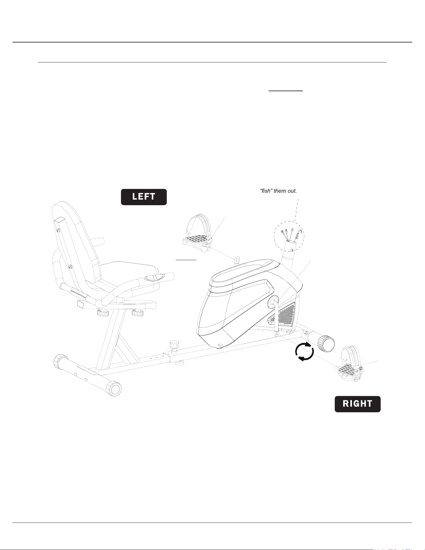
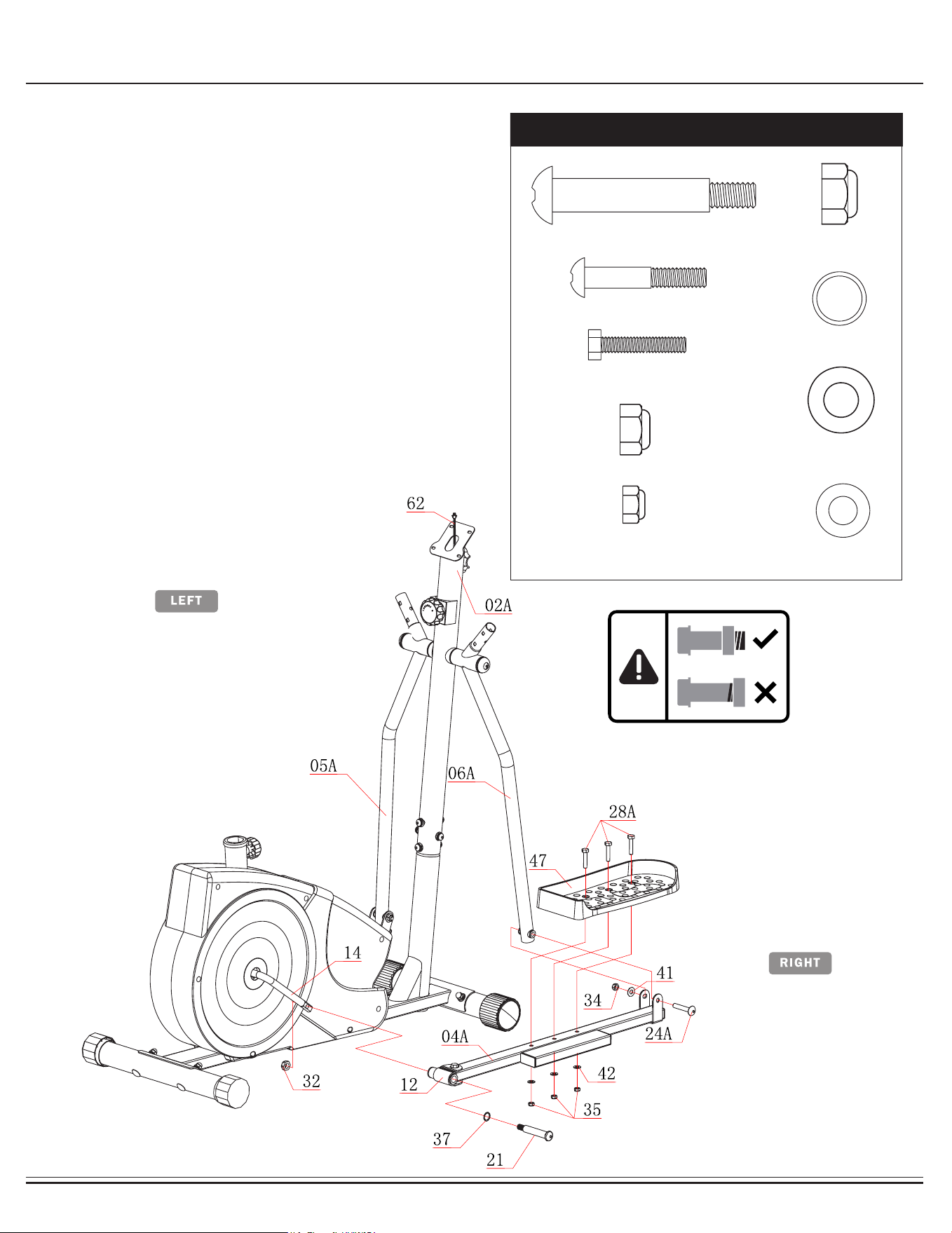
Align and attach the Pedal Connection Joint (#12) on the Right
Pedal Tube (#04A) to the Right Crank (#14). Insert a Bolt (#21)
through a Special Washer (#37) followed by Pedal Connection
Joint (#12) and Crank (#14). Screw the Bolt (#21) tightly into the
Crank (#14) by turning CLOCKWISE and then secure it with the
Nylon Nut (#32) by turning it COUNTERCLOCKWISE.
Align and attach the Right Coupler Bar (#06A) to the Right Pedal
Tube (#04A). Secure them together using a Bolt (#24A), Washer
(#41) and Nylon Nut (#34). Attach the Right Pedal (#47) to the
Right Pedal Tube (#04A) and secure them together using three
Hex Bolts (#28), three Washers (#42) and three Nylon Nuts
(#35).
Repeat this process on the other side.

BRM2720X / 2780 Page
10
Assembly STEP 4
Hardware Required
#21 Bolt (1/2"x97 mm)
[2 Pieces]
#24A Bolt (M10x58 mm)
[2 Pieces]
#28A Hex Bolt (M8x40 mm)
[6 Pieces]
#32 Nylon Nut (1/2")
[2 Pieces]
#34 Nylon Nut (M10)
[2 Pieces]
#37 Special Washer
(16mm)
[2 Pieces]
#41 Washer
(M10)
[2 Pieces]
#42 Washer
(M8)
[6 Pieces]
#35 Nylon Nut (M8)
[6 Pieces]
Align and attach the Pedal Connection Joint (#12) on the Right
Pedal Tube (#04A) to the Right Crank (#14). Insert a Bolt (#21)
through a Special Washer (#37) followed by Pedal Connection
Joint (#12) and Crank (#14). Screw the Bolt (#21) tightly into the
Crank (#14) by turning CLOCKWISE and then secure it with the
Nylon Nut (#32) by turning it COUNTERCLOCKWISE.
Align and attach the Right Coupler Bar (#06A) to the Right Pedal
Tube (#04A). Secure them together using a Bolt (#24A), Washer
(#41) and Nylon Nut (#34). Attach the Right Pedal (#47) to the
Right Pedal Tube (#04A) and secure them together using three
Hex Bolts (#28), three Washers (#42) and three Nylon Nuts
(#35).
Repeat this process on the other side.
BRM2720X / 2780 Page
11
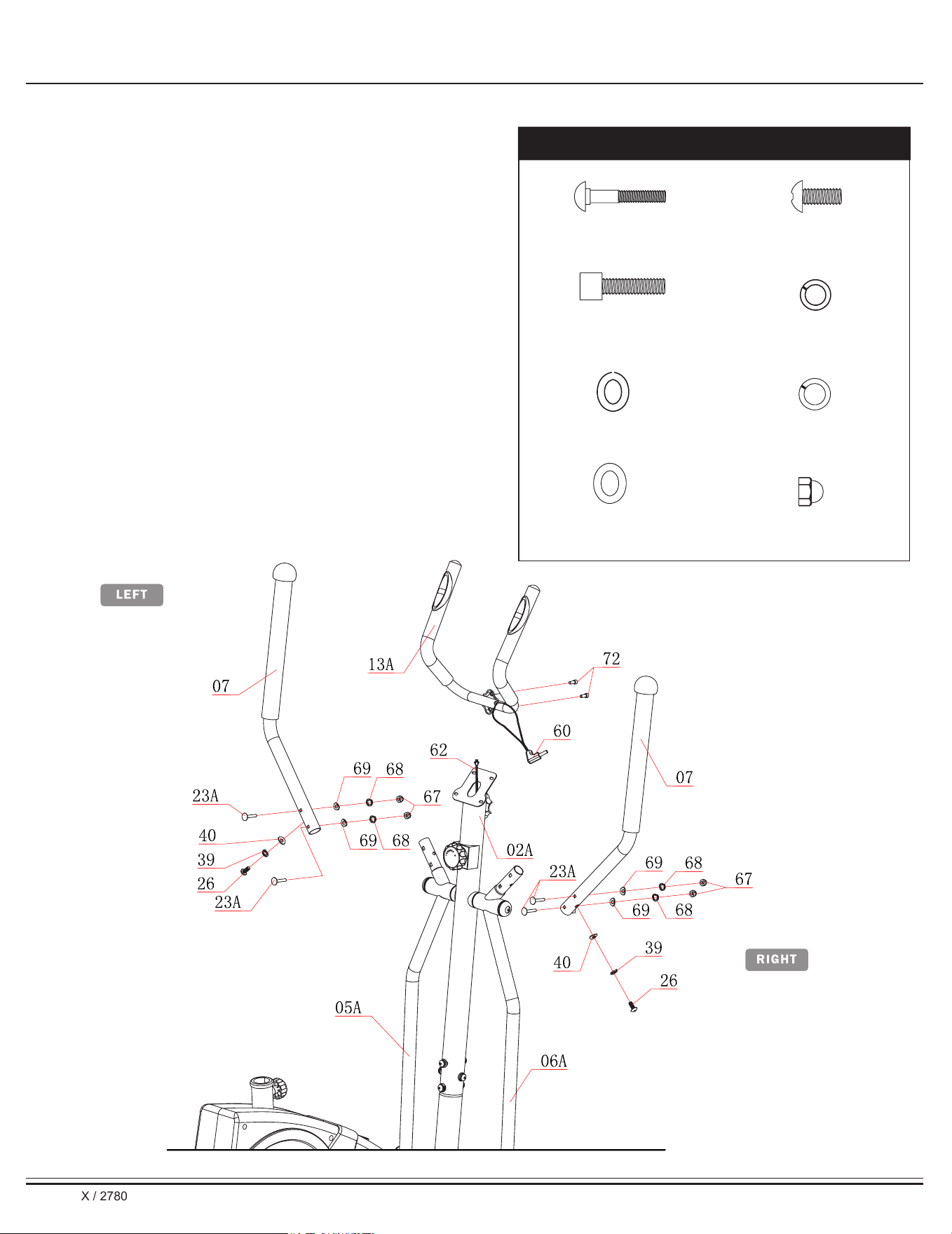
Assembly STEP 5
Remove the Bolts (#26), Spring Washers (#39) and Arc
Washers (#40) that are pre-assembled on the Left Coupler Bar
(#05A) and set them aside.
Insert the Left Handle Bar (#07) into the opening at the end of
the Left Coupler Bar (#05A) and secure it on the sid
e
using one Bolt (#26), one Spring Washer (#39)
and one
Arc Washer (#40) that was previously removed.
Insert two Carriage Bolts
(#23A) through the Left Handle Bar
(#07) and Left Coupler Bar (#05A).Secure them together using
two Arc Washers (#69), two Spring Washers (#68) and two Cap
Nuts (#67).
Repeat this process on the other side.
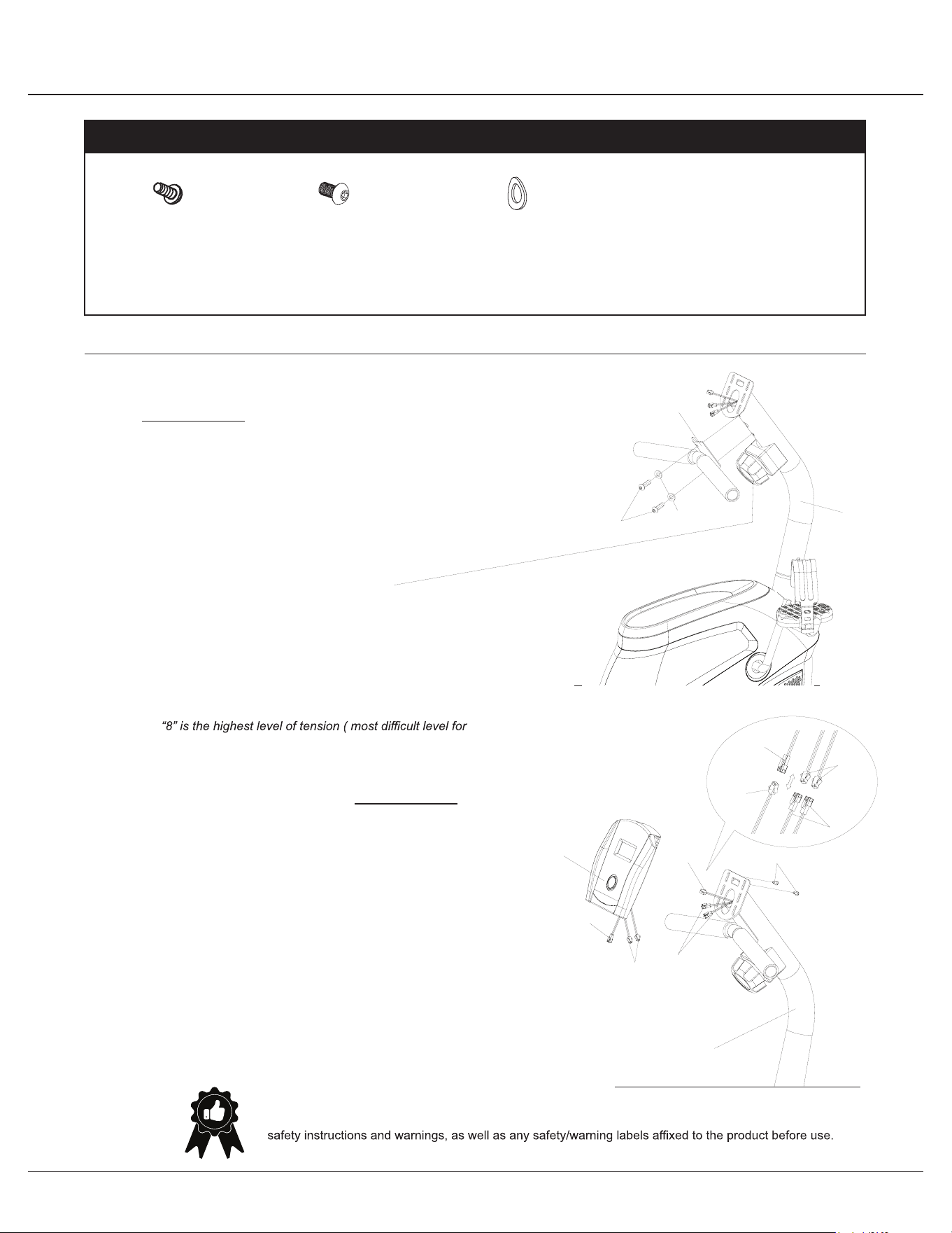
Install the Pulse Handle Bar (#13A)
onto the bracket of the
Center Post (#02A)
as shown in the illustration below using
two Bolts (#72A). Please ensure the Pulse Sensor Wire (#60)
is free and clear, avoiding pinching it during this assembly step.
You will need to connect this wire to the Monitor (#61) later.
Hardware Required
#40 Arc Washer (M8)
[2 Pieces]
#69 Arc Washer (M6)
[4 Pieces]
#39 Spring Washer (M8)
[2 Pieces]
#68 Spring Washer (M6)
[4 Pieces]
#67 Cap Nut (M6)
[4 Pieces]
#23A Carriage Bolt (M6x38 mm)
[4 Pieces]
#26 Bolt (M8x15)
[2 Pieces]
#72 Bolt (M8x30)
[2 Pieces]

BRM2720X / 2780 Page
11
Assembly STEP 5
Remove the Bolts (#26), Spring Washers (#39) and Arc
Washers (#40) that are pre-assembled on the Left Coupler Bar
(#05A) and set them aside.
Insert the Left Handle Bar (#07) into the opening at the end of
the Left Coupler Bar (#05A) and secure it on the sid
e
using one Bolt (#26), one Spring Washer (#39)
and one
Arc Washer (#40) that was previously removed.
Insert two Carriage Bolts
(#23A) through the Left Handle Bar
(#07) and Left Coupler Bar (#05A).Secure them together using
two Arc Washers (#69), two Spring Washers (#68) and two Cap
Nuts (#67).
Repeat this process on the other side.
Install the Pulse Handle Bar (#13A)
onto the bracket of the
Center Post (#02A)
as shown in the illustration below using
two Bolts (#72A). Please ensure the Pulse Sensor Wire (#60)
is free and clear, avoiding pinching it during this assembly step.
You will need to connect this wire to the Monitor (#61) later.
Hardware Required
#40 Arc Washer (M8)
[2 Pieces]
#69 Arc Washer (M6)
[4 Pieces]
#39 Spring Washer (M8)
[2 Pieces]
#68 Spring Washer (M6)
[4 Pieces]
#67 Cap Nut (M6)
[4 Pieces]
#23A Carriage Bolt (M6x38 mm)
[4 Pieces]
#26 Bolt (M8x15)
[2 Pieces]
#72 Bolt (M8x30)
[2 Pieces]
BRM2720X / 2780 Page
12
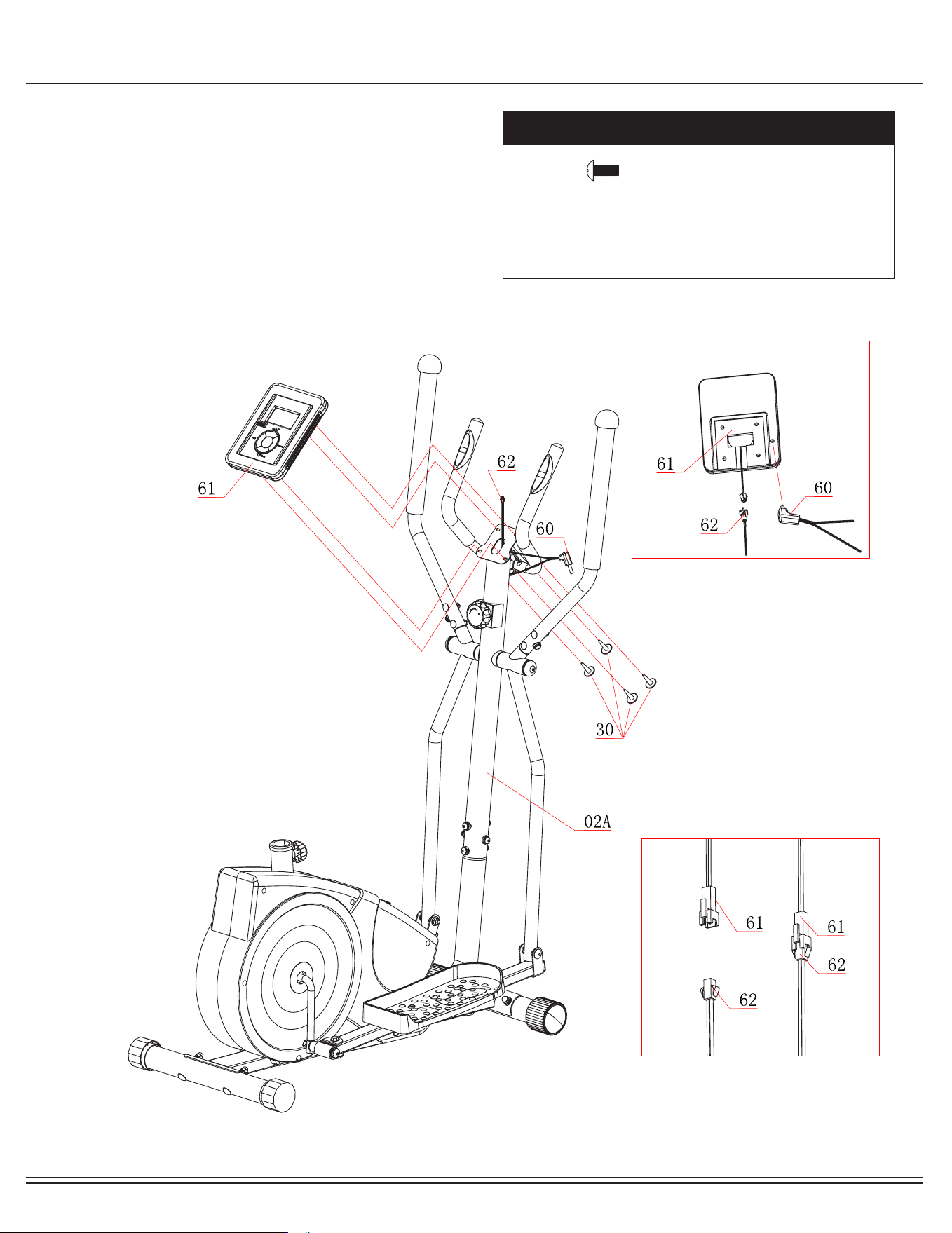
Assembly STEP 6
Remove the Bolts (#30) that are pre-assembled on the back of the
Monitor (#61) and set them aside as they will be used in a later
process.
Connect the Monitor Wire (Upper) (#62) to the Monitor (#61) and
connect the Pulse Sensor Wire (#60) to the Monitor (#61).
Secure the Monitor (#61) to the bracket of the Center Post (#02A)
with four Screws (#30) that were previously removed.
Hardware Required
#30 Screw (M5x12mm)
[4 Pieces]
A
B

BRM2720X / 2780 Page
12
Assembly STEP 6
Remove the Bolts (#30) that are pre-assembled on the back of the
Monitor (#61) and set them aside as they will be used in a later
process.
Connect the Monitor Wire (Upper) (#62) to the Monitor (#61) and
connect the Pulse Sensor Wire (#60) to the Monitor (#61).
Secure the Monitor (#61) to the bracket of the Center Post (#02A)
with four Screws (#30) that were previously removed.
Hardware Required
#30 Screw (M5x12mm)
[4 Pieces]
A
B
BRM2720X / 2780 Page
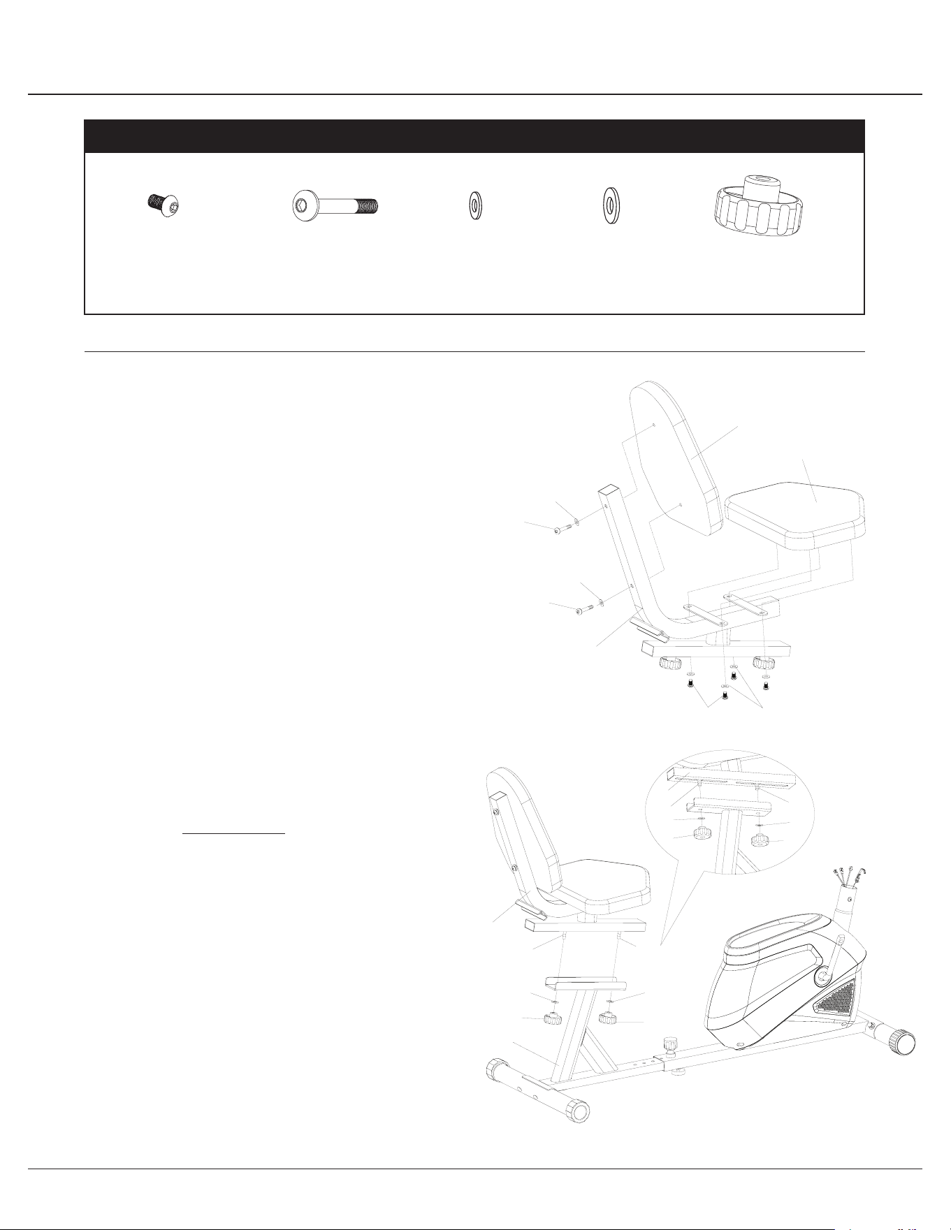
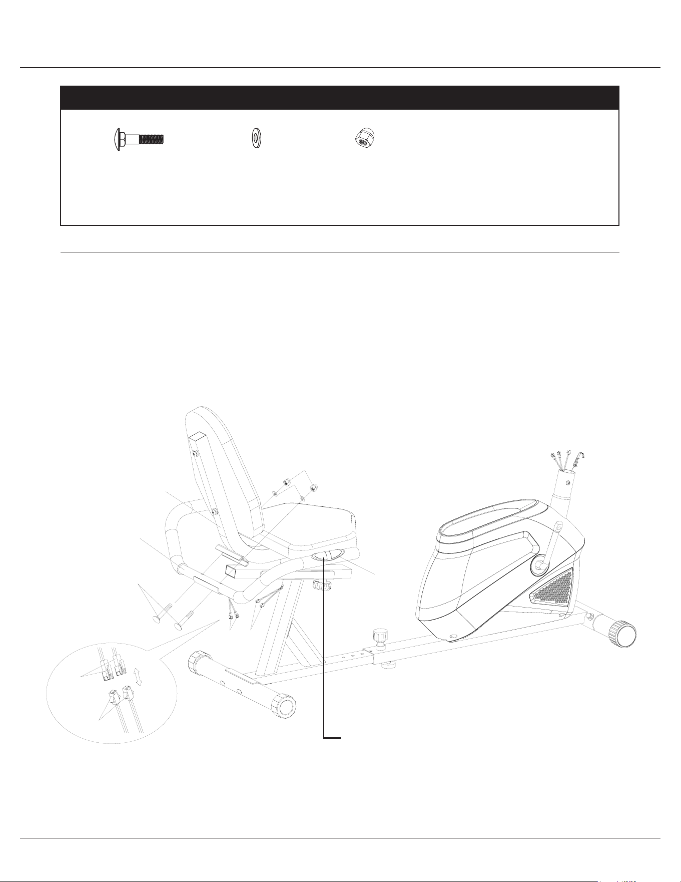
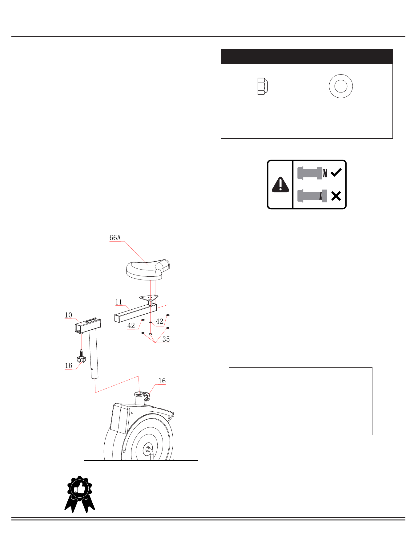
13
Assembly STEP 7
Remove the three Washers (#42) and three Nylon Nuts (#35) that
are pre-assembled on the back of the Seat (#66A) and set them
aside as they will be used in a later process.
Attach the Seat (#66A) onto the Horizontal Seat Bar (#11) and
make sure that the Seat (#66A) is pointing directly toward the short
end of it and then tighten with three Washers (#42) and three
Nylon Nuts (#35) that were previously removed. The Knob Bolt
(#16) can be loosened to adjust the distance of the seat from the
handlebars. Make sure to tighten the knob after making any
adjustment.
Insert the Seat Post (#10) into the mouth of the post that is
protruding from the Main Frame (#01A). Make sure the holes in the
Seat Post (#10) are facing the front before inserting. The Knob
Bolt (#16) has a safety feature that allows you to loosen
it by turning it counter clockwise three times as you pull it outward.
Adjust the seat height and then pop the knob back in. Tighten the
knob by turning CLOCKWISE.
Hardware Required
#35 Nylon Nut (M8)
[3 Pieces]
#42 Washer (M8)
[3 Pieces]
WARNING:
Do not remove the Seat (#66AA) for any reason
after you have installed it.
Exercising on this unit without the Seat (#66AA)
can result in SERIOUS INJURY. Ensure the seat is
locked in place by tightening the two knobs prior
using the unit.
THE ASSEMBLY PROCESS IS NOW COMPLETE.
However, for your own safety, please make sure to read this entire Owner’s Manual which includes
safety instructions and warnings, as well as any safety/warning labels axed to the product before use.
For your safety , please visually and functionally inspect and test the unit after assembly is complete.

BRM2720X / 2780 Page
14
Computer Operation
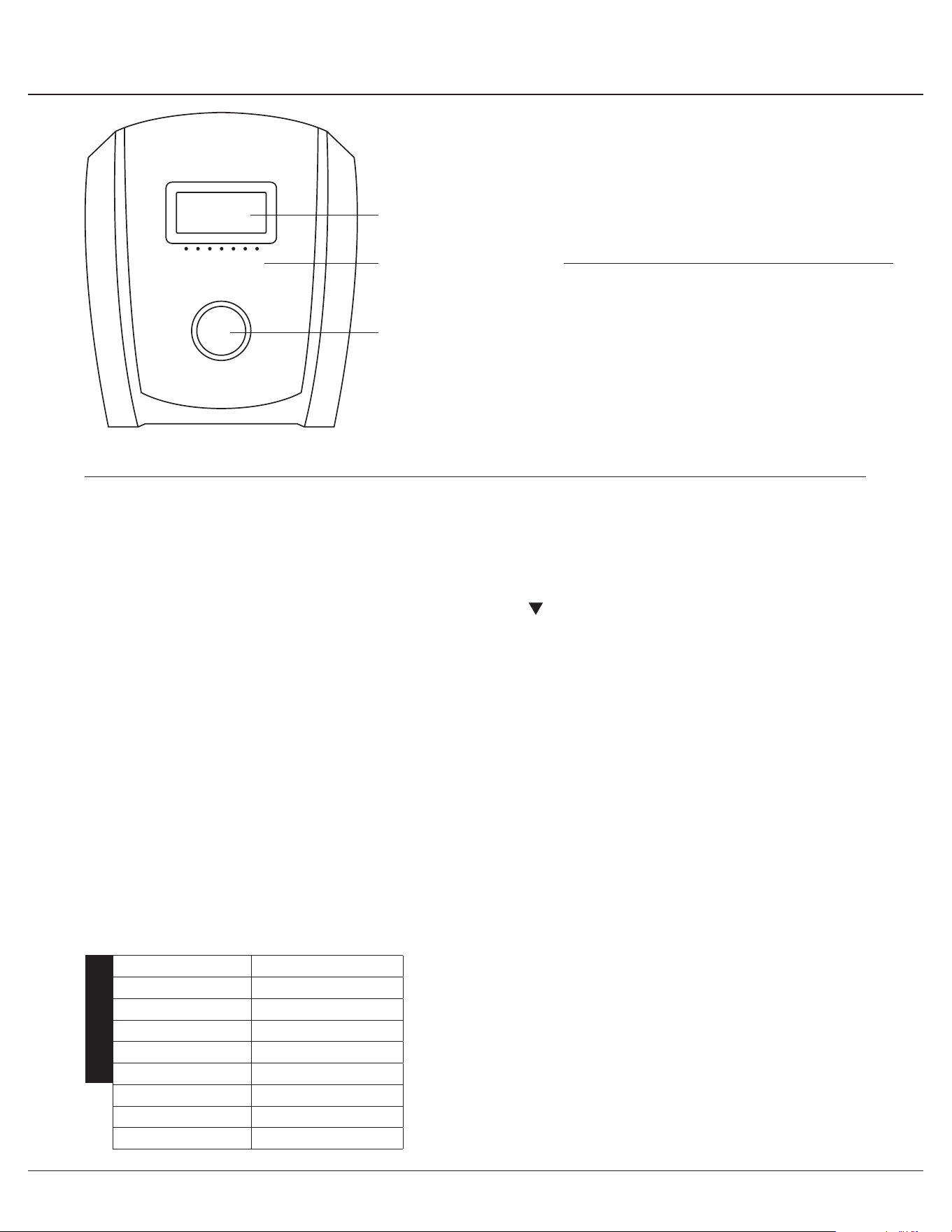
KEY GUIDE
FUNCTION AND OPERATIONS
RECOVERY:
Press this button to enter into pulse recovery detection. ENTER: Press this button to perform any of
the tasks below:
1. Enter into mode-setting for any of the functions:
Normal→Time→DIST→CAL→T.H.R
2. Conrm the setting values
3. Hold for 3 seconds to reset all of the values to zero.
UP: Increase the setting value of the following functions.
Time→DIST→CAL→T.H.R
DOWN: Decrease the setting value of the following functions.
Time→DIST→CAL→T.H.R
AUTO ON/OFF:
The monitor will automatically begin to measure & display if the exercise machine is in motion. If the
machine is not in use and/or not in motion for over 4 minutes, the monitor will turn o and reset all
function values to zero.
TIME:
Press ENTER button until the TIME function is selected and press the UP or DOWN button to enter
the value you wish to choose.
Count up:
If you do not set a time value with the UP or DOWN button, the monitor will count up the time from
00:00~99:59.

BRM2720X / 2780 Page
14
Computer Operation
KEY GUIDE
FUNCTION AND OPERATIONS
RECOVERY:
Press this button to enter into pulse recovery detection. ENTER: Press this button to perform any of
the tasks below:
1. Enter into mode-setting for any of the functions:
Normal→Time→DIST→CAL→T.H.R
2. Conrm the setting values
3. Hold for 3 seconds to reset all of the values to zero.
UP: Increase the setting value of the following functions.
Time→DIST→CAL→T.H.R
DOWN: Decrease the setting value of the following functions.
Time→DIST→CAL→T.H.R
AUTO ON/OFF:
The monitor will automatically begin to measure & display if the exercise machine is in motion. If the
machine is not in use and/or not in motion for over 4 minutes, the monitor will turn o and reset all
function values to zero.
TIME:
Press ENTER button until the TIME function is selected and press the UP or DOWN button to enter
the value you wish to choose.
Count up:
If you do not set a time value with the UP or DOWN button, the monitor will count up the time from
00:00~99:59.

BRM2720X / 2780 Page
15
Computer Operation
FUNCTION AND OPERATIONS (CONTINUE)
Count down:
If you set a time value from 1:00~99:00 minute(s), the monitor will count down from the value you
have selected. Once you have reached the set value, the monitor will beep and signal you have
reached your set value.
SPEED:
Displays your workout speed in miles per hour. The monitor will display the current speed from
0.00 ~ 99.9 mile(s) per hour.
RPM:
Displays your workout RPM (rotations per minute). The monitor will display the current RPM from
15 ~ 999.
DISTANCE:
Press the ENTER button until you select the DIS function and press the UP or DOWN button to enter
the value you wish to choose.
Count up:
If you do not set a time value with the UP or DOWN button, the monitor will count up the distance
from 0.1~999.
Count down:
If you set a time value from 1.0~999 mile(s), the monitor will count down from the value you have se-
lected. Once you have reached the set value, the monitor will beep and signal you have reached your
set value.
CALORIE:
Press the ENTER button until you select the CAL function and press the UP or DOWN button to enter
the value you wish to choose.
Count up:
If you do not set a time value with the UP or DOWN button, the monitor will count up the distance
from 0.1~999.
Count down:
If you set a calorie value from 1.0~999, the monitor will count down from the value you have selected.
Once you have reached the set value, the monitor will beep and signal you have reached your set
value.
PULSE (Target Heart Rate):
Press the ENTER button until you select the T.H.R function and press the UP or DOWN button to
enter the value you wish to choose.
Pulse Limit:
If you set a value between the allowed limits (60 to 220), the monitor will measure your pulse. Once
you have reached the set value, the monitor will ash until your pulse reading is below your set value.

BRM2720X / 2780 Page
16
Computer Operation
FUNCTION AND OPERATIONS (CONTINUE)
BATTERY INSTALLATION/REPLACEMENT:
Place the palms of your hands and grip lightly on both the contact pads and the monitor will display
your heartbeat rate in beats per minute (BPM) on the LCD display. NOTE: If there is no pulse signal
input within 16 seconds, the display will indicate a “P”. This is a power saving mechanism. The user
can press any key to restart the pulse (T.H.R.) function.
(PULSE) RECOVERY:
Pulse recovery is a measure of how quickly you return to your resting heart rate after a workout.
When you stop from exercising and desire to test your pulse recovery: Press the RECOVERY button
and place the palms of your hands on both of the contact pads for one minute. The monitor will show
your pulse recovery ratio on the LCD between 1.0 to 6.0 (1.0 being the best and 6.0 being the worst)
with increments of 0.1.
CAUTION:
Operating temperature: 0°C - +50°C.
Storage temperature: -10°C - +60°C.
1. Lift o the battery cover and place two SIZE-AAA or UM-4 batteries into the battery housing on
back of monitor with the +/- sides installed correctly.
2. Please ensure batteries are correctly positioned and battery springs are in proper contact with
batteries.
3. Replace battery cover and ensure it is tightly closed.
4. Battery life is approx. 1 year under normal usage.
5. If the display is illegible or only partial segments appear, remove batteries and wait 15 seconds
before reinstalling.
6. Removing the batteries will erase the computer memory.
NOTES (Regarding the Computer Monitor):
Warning: This device complies with Part 15 of the FCC Rules. Operation is subject to the following two conditions:
(1) This device may not cause harmful interference.
(2) This device must accept any interference received, including interference that may cause undesired operation.
Caution:
This equipment has been tested and found to comply with the limits for a Class B digital device, pursuant to part 15 of the FCC Rules.
These limits are designed to provide reasonable protection against harmful interference in a residential installation. This equipment generates, uses and
can radiate radio frequency energy and, if not installed and used in accordance with the instructions, may cause harmful interference to radio
communications. However, there is no guarantee that interference will not occur in a particular installation. If this equipment does cause harmful
interference to radio or television reception, which can be determined by turning the equipment o and on, the user is encouraged to try to correct the
interference by one or more of the following measures:
- Reorient or relocate the receiving antenna.
- Increase the separation between the equipment and receiver.
- Connect the equipment into an outlet on a circuit dierent from that to which the receiver is connected.
- Consult the dealer or an experienced radio/TV technician for help.

BRM2720X / 2780 Page
17
Safety and Maintenance
• Please review all safety instructions and warnings in this entire Owner’s Manual, as well as any safety/warning labels
axed to the product before use.
• Do not use solvent cleaners. If you are in any doubt, do not use your cleansing product; contact
CUSTOMER SUPPORT.
• The specic parts on your unit which may see possible signs of wear after prolonged use are listed as follows
(please check these parts before each use):
Left/Right Pedals (#46/#47); Handlebars (#07).
• For any replacement warning labels, please contact our CUSTOMER SUPPORT at
1 (888) 266A-6789 or 1 (909) 598-9876, or mail in a written request to:
Body Flex Sports Inc.
21717 Ferrero Parkway
Walnut, CA 91789
More detailed information about how to reach our CUSTOMER SUPPORT may be found on Page 2 of the
Owner’s Manual under the “CUSTOMER SUPPORT” section.
Maintenance & Care
• Make sure all nuts, bolts, and screws are tightened prior to use.
• Be sure that all adjustment locking devices and safety devices are properly engaged prior to use!
• Never over-tighten the above-mentioned devices and parts to avoid damage to the unit.
• Check for loose parts and components and make proper adjustments prior to use.
• Check to see if there are any tears or bends in the welding or metal prior to use. If tears or bends are found,
DO NOT use the unit and contact our CUSTOMER SUPPORT.
• Extreme care must be taken to not allow your feet, ngers, hair, clothing, and/or any loose items to be snagged into
any portion of the bike when the unit is in motion. Failure to follow these instructions could result in serious injury,
including the loss of ngers.
• Always wait for the pedals and other moving parts (which can gain great momentum during riding) to come to a
complete stop before dismounting the unit to avoid serious injury.
NOTE: Always wait for the pedals and/or any other moving parts (which can gain great momentum during riding)
to come to a complete stop before dismounting the unit to avoid serious injury.
• To reduce speed on the bike, you may use the combinations of your feet on the Left/Right Pedals (#46/47) and your
hands on the Handlebars (#07) to gently and safely apply counter-momentum.
• Wait for the pedals to come to a complete stop.
• Now you may safely dismount the unit
NOTE:
To safely move, transport, and/or store the unit, please seek the help of capable assistants (minimum of 2 people).
The unit has integrated Front Rollers purposely intended to help ease this process.
• Position one person on each side at the front of the bike toward the handle Bar
(one person on the left, and one on the right).
• Have each person use both hands to grip the corresponding Pulse Handle Bar (#13A).
(These are the safest areas to avoid injury during this process.)
• Have both people simultaneously lift the rear end of the unit, leaving the weight and pressure into the front of the unit
and onto the Front Rollers to move/transport the unit to the desired area.
Safety & Warning
How To (Emergency) Stop
How To Move/Transport The Bike For

BRM2720X / 2780 Page
18
Troubleshooting
(AFTER COMPLETE ASSEMBLY)(AFTER COMPLETE ASSEMBLY)
TROUBLESHOOT AREA SOLUTION
Hand Pulse Signal
If the computer is not picking up your hand pulse signal (or you are
getting inaccurate readings), please adjust the following:
1. Slightly moisten/dampen the palms with water so the sensors can detect a pulse
signal.
2. Do not grip the sensors too tightly. Only moderate pressure need be applied.
3. Gripping the sensors too tightly restricts and seizes detection of your pulse.
4. Remove any rings or jewelry to prevent interference.
5. Check to ensure all pulse sensor wires are properly connected and are not dam-
aged.
6. You may need to refer to installation/assembly directions for the pulse sensor
wires in this manual.
Calories/Distance/
Time (Etc.)
If the computer is not displaying the CALORIES/DISTANCE/TIME/(ETC.)
functions (or you are getting inaccurate readings), please adjust the following:
1. Check to ensure all computer sensor wires are properly
connected and are not damaged.
2. You may need to refer to installation/assembly directions for the sensor wires in
this manual.
Computer Display
If the computer display is blank & not displaying any data (or does not appear to
power on), please adjust the following:
1. Check to ensure all sensor wires are all properly connected and are not dam-
aged.
2. Check to ensure the AC Adapter* or Batteries* are properly plugged in or fully
charged.
3. Check your product manual to determine if your model uses either AC Adapter or
batteries to power your unit.
BRM2720X / 2780 Page
19
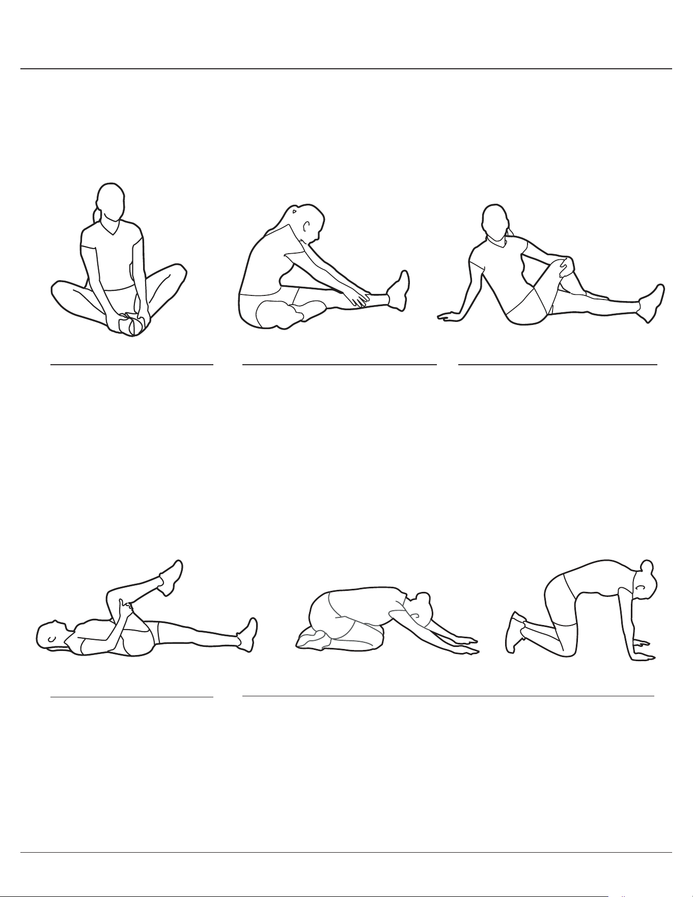
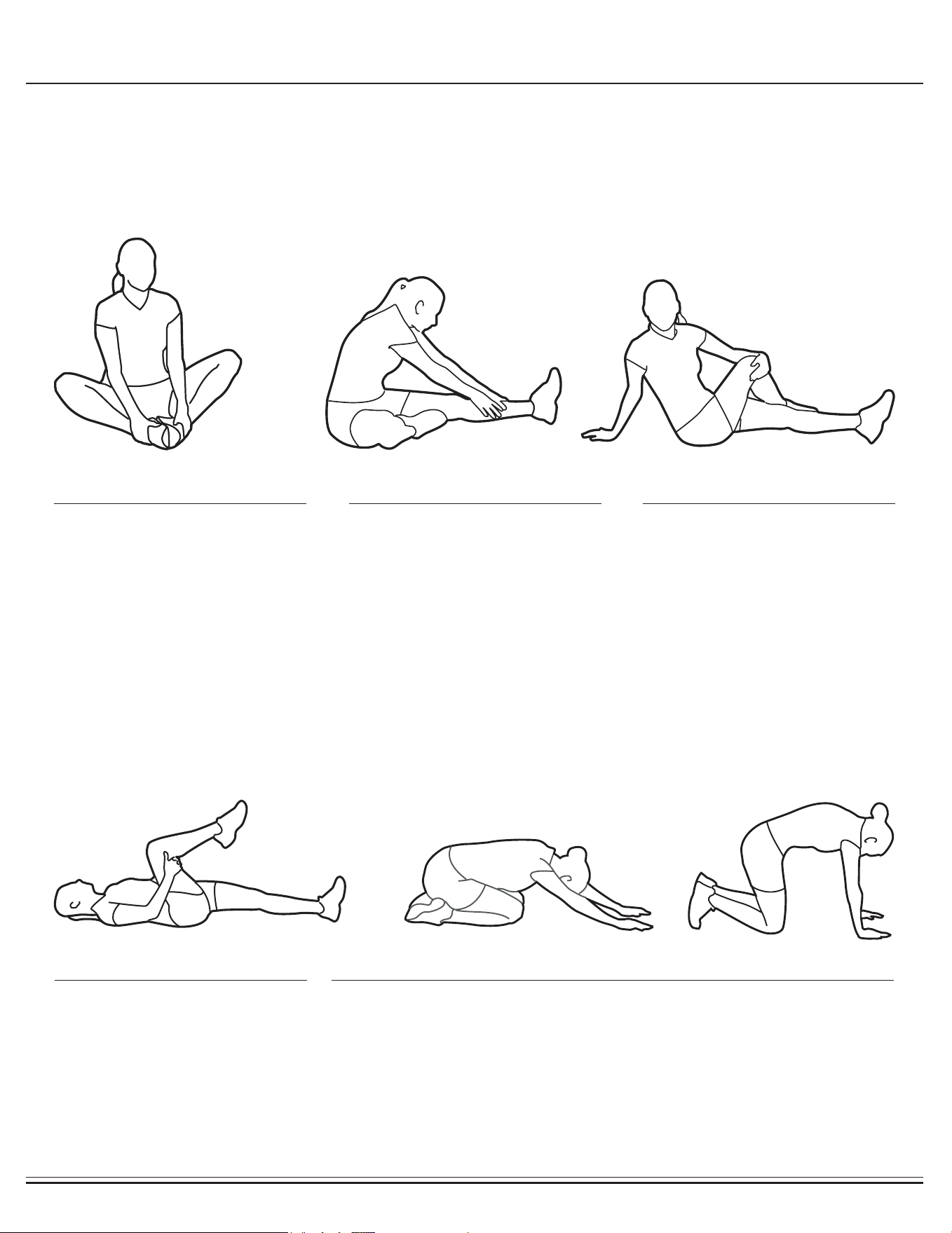
Warm-Up Instructions
1. Sit with your knees exed and
soles of feet together.
2. Hold your ankles and bend
at your hips (keep your back
straight) as you press your
knees toward the oor with your
elbows.
1. Lie on your back and raise
your right leg as you clasp both
hands under the back of the
knee. Keep your left leg straight.
2. Gently pull your right leg toward
your trunk without
raising your upper body. Switch
leg positions and repeat.
1. Sit with your left leg extended
and bend your right leg at the
knee as you place the sole of
your right foot against the inner
thigh of your extended leg.
2. Flex the foot of your extended
leg (toes pointed toward
ceiling) and gently bend forward
from your hips; keep your back
straight.
3. Reach your hands on your
extended leg as far as possible
and then switch legs and repeat.
1. Assume the depicted position on your hands and knees. Stretch your
hands out in front of you and then slowly start to pull them back in toward
your body as you tuck your chin and arch your back upward.
2. Return to the starting position slowly.
1. Sit with your leg extended and
bend your right knee as you
cross your right leg over your
left leg. Your right foot of your
extended leg foot should be at
on the oor alongside your left
knee.
2. Place your left arm on the
outside of your right leg and pull
against that leg while twisting
your trunk as far as possible to
the right. Place your right hand
on the oor behind your but-
tocks. Reverse leg positions and
repeat.
Before use, you must read and understand all instructions & warnings stated in this Owner’s Manual as well as posted
on the equipment. Before beginning any exercise program including the following exibility exercises, please consult with
your physician.
The following exibility exercises are provided to you as a means to prevent injury while you are exercising. A proper
warm-up routine decreases the chance of injuring your muscles while you are exercising. Please take the time to do these
exibility exercises before and after each time you exercise.
Groin Stretch
Groin Stretch
Hamstring Stretch
Trunk Flexion, Prone
Trunk Twister

BRM2720X / 2780 Page
19
Warm-Up Instructions
1. Sit with your knees exed and
soles of feet together.
2. Hold your ankles and bend
at your hips (keep your back
straight) as you press your
knees toward the oor with your
elbows.
1. Lie on your back and raise
your right leg as you clasp both
hands under the back of the
knee. Keep your left leg straight.
2. Gently pull your right leg toward
your trunk without
raising your upper body. Switch
leg positions and repeat.
1. Sit with your left leg extended
and bend your right leg at the
knee as you place the sole of
your right foot against the inner
thigh of your extended leg.
2. Flex the foot of your extended
leg (toes pointed toward
ceiling) and gently bend forward
from your hips; keep your back
straight.
3. Reach your hands on your
extended leg as far as possible
and then switch legs and repeat.
1. Assume the depicted position on your hands and knees. Stretch your
hands out in front of you and then slowly start to pull them back in toward
your body as you tuck your chin and arch your back upward.
2. Return to the starting position slowly.
1. Sit with your leg extended and
bend your right knee as you
cross your right leg over your
left leg. Your right foot of your
extended leg foot should be at
on the oor alongside your left
knee.
2. Place your left arm on the
outside of your right leg and pull
against that leg while twisting
your trunk as far as possible to
the right. Place your right hand
on the oor behind your but-
tocks. Reverse leg positions and
repeat.
Before use, you must read and understand all instructions & warnings stated in this Owner’s Manual as well as posted
on the equipment. Before beginning any exercise program including the following exibility exercises, please consult with
your physician.
The following exibility exercises are provided to you as a means to prevent injury while you are exercising. A proper
warm-up routine decreases the chance of injuring your muscles while you are exercising. Please take the time to do these
exibility exercises before and after each time you exercise.
Groin Stretch
Groin Stretch
Hamstring Stretch
Trunk Flexion, Prone
Trunk Twister
BRM2720X / 2780 Page
20
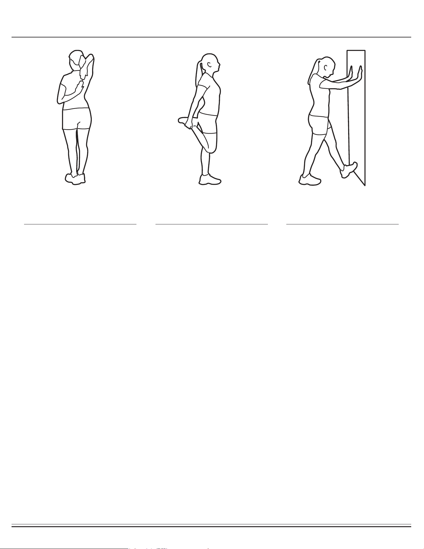
Warm-Up Instructions
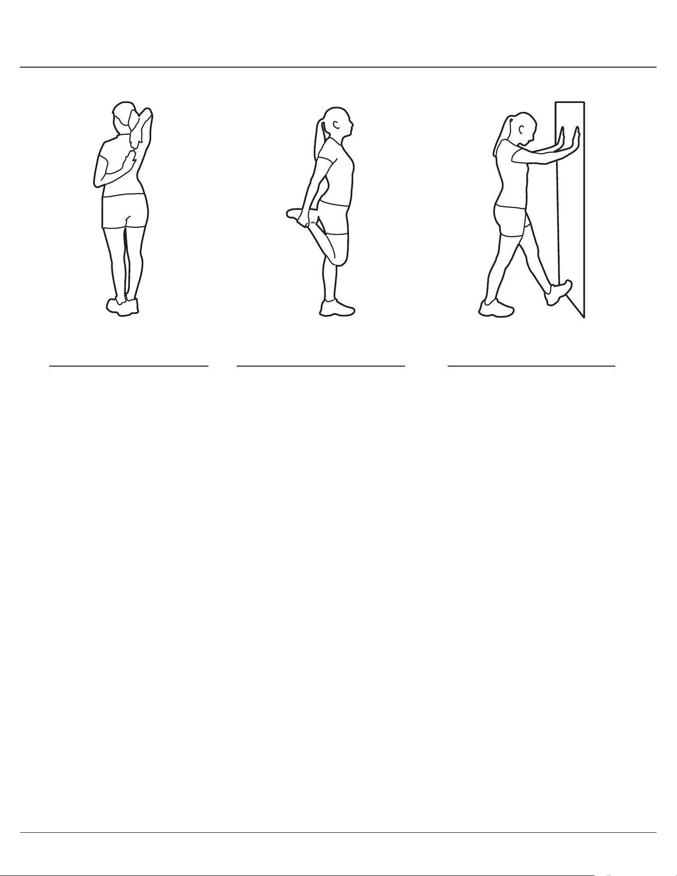
1. Bring your right hand over your
right shoulder to the
upper back and bring your left
hand under your left shoulder to
the upper back.
2. Try to reach your ngertips. If
you are not able to reach your
ngertips, use a towel as an
extension of your hands and
gently pull one hand toward the
other.
Reverse arm positions and
1. Stand on your left leg and hold
onto a support with your left
hand.
2. Flex your right leg behind you,
grasp your ankle or foot with
your right hand and pull your
foot toward your buttocks. Keep
your back straight and right
knee pointed down.
Repeat on the other leg.
1. Place both hands against a wall
to aid your balance. Press the
ball of your left foot against the
wall and keep the heel of the
same foot rested on the oor
(make sure your left knee is
bent).
2. Slowly start to straighten your
left knee and you will feel the
muscles in your left calf stretch.
Switch leg positions and repeat.
Shoulder Stretch Quadriceps Stretch Calf Twister

BRM2720X / 2780 Page
20
Warm-Up Instructions
1. Bring your right hand over your
right shoulder to the
upper back and bring your left
hand under your left shoulder to
the upper back.
2. Try to reach your ngertips. If
you are not able to reach your
ngertips, use a towel as an
extension of your hands and
gently pull one hand toward the
other.
Reverse arm positions and
1. Stand on your left leg and hold
onto a support with your left
hand.
2. Flex your right leg behind you,
grasp your ankle or foot with
your right hand and pull your
foot toward your buttocks. Keep
your back straight and right
knee pointed down.
Repeat on the other leg.
1. Place both hands against a wall
to aid your balance. Press the
ball of your left foot against the
wall and keep the heel of the
same foot rested on the oor
(make sure your left knee is
bent).
2. Slowly start to straighten your
left knee and you will feel the
muscles in your left calf stretch.
Switch leg positions and repeat.
Shoulder Stretch Quadriceps Stretch Calf Twister

THANK YOU FOR YOUR PURCHASE
MODEL NO.: BRM2720X/BRM2780
along with your sales receipt as proof of purchase.
Serial Number :
Date of Purchase :
Retailer :
Body Flex Sports Inc.
21717 Ferrero
Parkway
Walnut, CA 91789
Phone
Ver. 11/28/2017 Printed in China
: 1 (888) 266A-6789
Fax : 1 (909) 598-6707
Email