General Information
BRB 5200 Page 1
Warranty
Body Flex Sports warrants your product for
a period of 1 year for the frame and 90 days
on all parts if the item is used for the intended
purpose, properly maintained and not used
commercially. Any alterations or incorrect
assembly of the product will void this warranty.
Proof of purchase must be presented for any
warranty validation (no exceptions). This
warranty applies to the original purchaser only
and is not transferable.
This warranty does not cover abuse or defects
caused during use, storage or assembly.
During the warranty period, Body Flex Sports
reserves the right to:
a). provide replacement parts to the
purchaser in an effort to repair the item.
b). repair the product returned to our
warehouse (at the purchaser’s cost).
c). replace the product if neither of the two
previously mentioned actions effect repair.
This warranty does not cover normal wear and
tear on upholstery.
Questions
If you have any questions concerning the
assembly of your item or if any parts are
missing, please DO NOT RETURN THE
ITEM TO THE STORE OR CONTACT THE
RETAILER. Our dedicated customer service
staff can help you with any questions you may
have regarding the assembly of this unit and
can also mail you replacement parts.
Customer Support
Customer Support is open 9:00 a.m. to 5:00
p.m. (Pacic Time) Monday through Friday.
Please contact us by any of the following
means.
Body Flex Sports, Inc.
21717 Ferrero Parkway, Walnut, CA 91789
Telephone: (888) 266 - 6789
Fax: (909) 598 - 6707
Email: info@bodyexsports.com
Safety
Before you undertake any exercise program,
please be sure to consult with your doctor.
Frequent strenuous exercise should be
approved by your doctor and proper use
of your product is essential. Please read
this manual carefully before commencing
the assembly of your product or starting to
exercise.
• Please keep all children away from this item
when in use. Do not allow children to climb or
play on them when they are not in use.
• Supervise teenagers while they use this unit.
• For your own safety, always ensure that there
is at least 3 feet of free space in all directions
around your product while you are exercising.
• Regularly check to see that all nuts, bolts and
ttings are securely tightened. Periodically
check all moving parts for obvious signs of
wear or damage.
• Clean only with a damp cloth, do not use
solvent cleaners. If you are in any doubt, do
not use your product; contact CUSTOMER
SUPPORT.
• Before use, always ensure that your product
is positioned on a solid, at surface. If
necessary, use a rubber mat underneath to
reduce the possibility of slipping.
• Always wear appropriate clothing and
footwear such as training shoes when
exercising. Do not wear loose clothing that
could become caught in moving parts during
exercise.
• Do not use this unit if it is not functioning
properly or if it is not fully assembled.
• Do not use this unit for commercial purposes.
Storage and Use
Your product is intended for use in clean
dry conditions. You should avoid storage in
excessively cold or damp places as this may
lead to corrosion and other related problems.
Weight Limit
Your product is suitable for users weighing:
250 pounds or less.
Downloaded from www.ManualsFile.com manuals search engine
BRB 5200 Page 2
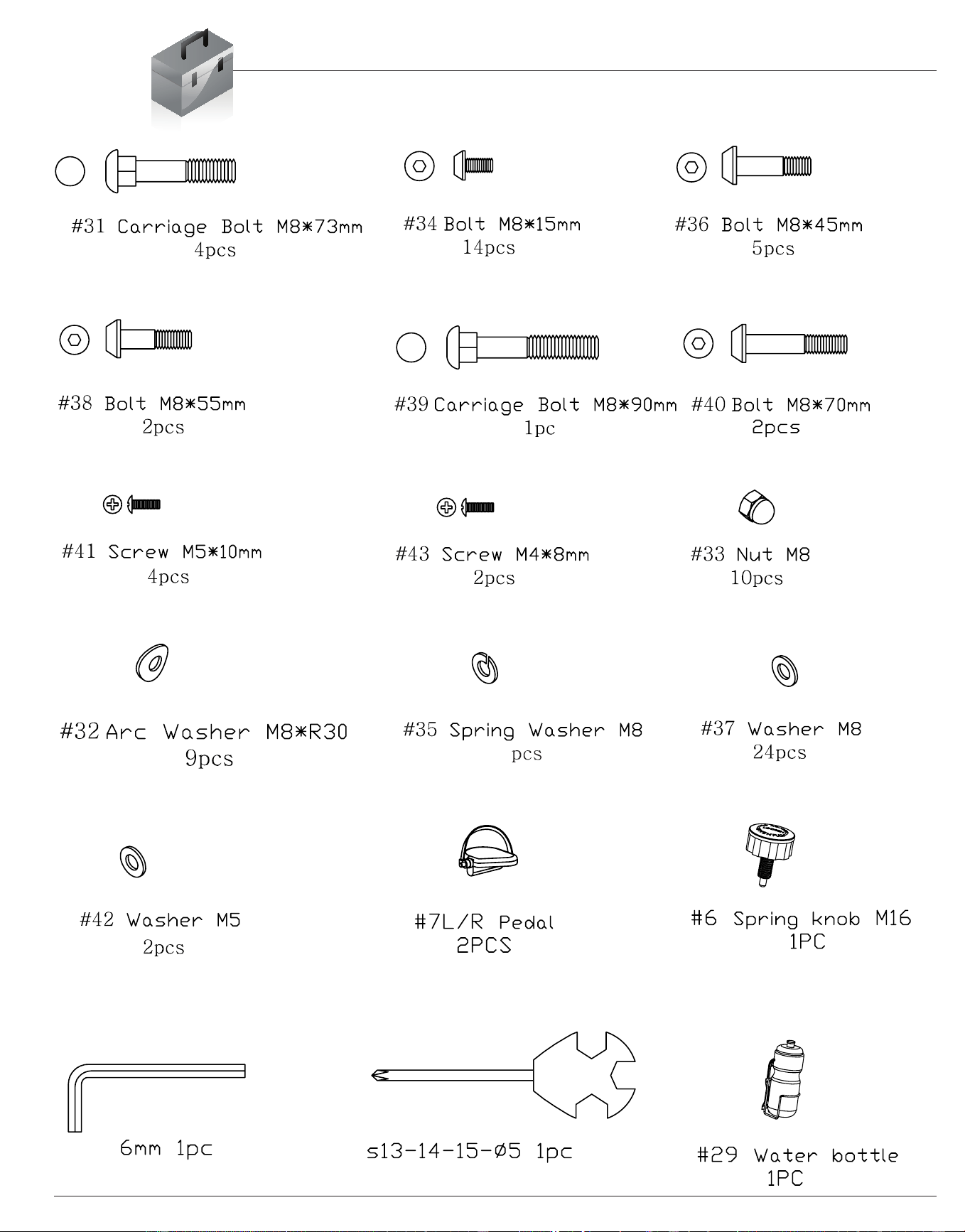
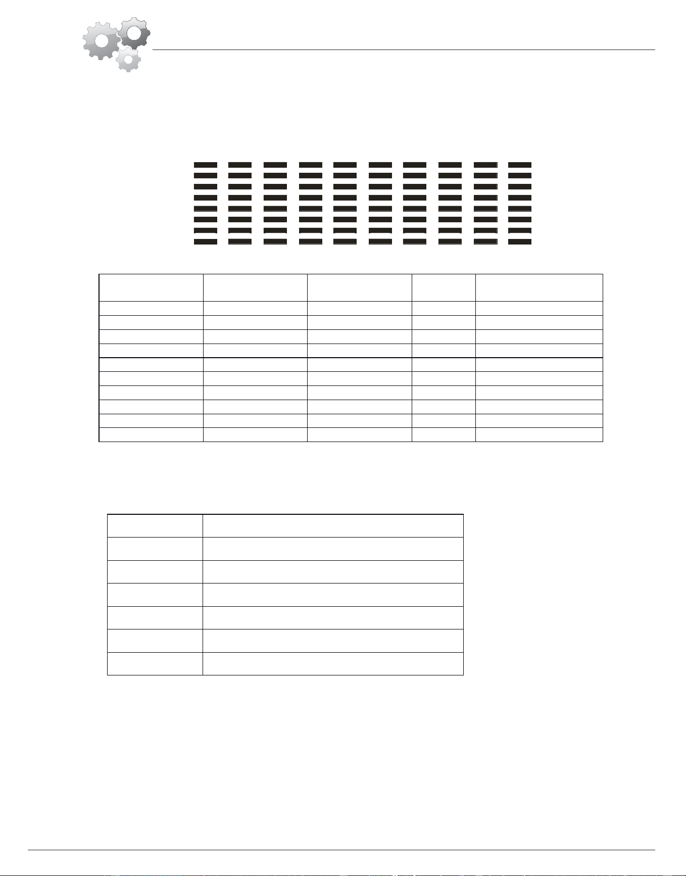
Hardware & Tool List
The following hardware is used to assemble your unit. Please take a moment to familiarize yourself with these
items. Please note some of this hardware is already pre-assembled on the machine. Do not be alarmed if you
see parts on this page that are not included in your hardware packet
6
Downloaded from www.ManualsFile.com manuals search engine

BRB 5200 Page 3
Parts Listing
The following parts list describes all of the parts illustrated on the
exploded diagram on the following page. Please note, most of
these parts are already pre-assembled on your unit.
# Description # Description
1Rearstabilizer
21
Seat cushion frame
2 Adjustable end cap for rear stabilizer 22 End cap (38*38mm)
3 Bottom frame 23A Sensor wire (lower)
4 Bottom frame sleeve 23B Sensor wire (middle)
5 Bumper 23C Sensor wire (upper)
6 Spring knob 24 Front post
7R Right Pedal 25
End cap (φ25)
7L Left Pedal 26 Foam grip
8 Main frame 27 Front handle bar
9 End cap f or front stabilizer 28 Monitor
10 Front stabilizer 29 Water bottle
11A Sensor wire A 30 Water bottle holder
11B Sensor wire B 31 Carriage Bolt (M8*73mm)
11C Sensor wire C 32 Arc Washer (M8*R30)
11D Sensor wire D 33 Nut (M8)
11E Sensor wire E 34 Bolt (M8*15mm)
11F Sensor wire F 35 Spring Washer (M8)
12 Backrest cushion frame 36 Bolt (M8*45mm)
13 Seat cushion support frame 37 Washer (M8)
14 Grommet 38 Bolt (M8*55mm)
15 Rear handle bar 39 Carriage bolt (M8*90mm)
16 Foam grip (long) 40 Bolt (M8*70mm)
17 Pulse sensor 41 Screw (M5*10mm)
18 End cap 50*50mm 42 Washer (M5)
19 Backrest cushion 43 Screw (M4*8mm)
20 Seat cushion
44 Screw (M4*19mm)
Downloaded from www.ManualsFile.com manuals search engine
BRB 5200 Page 4
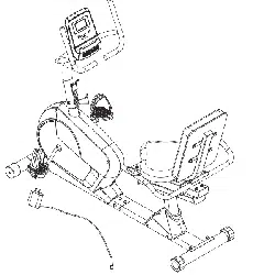
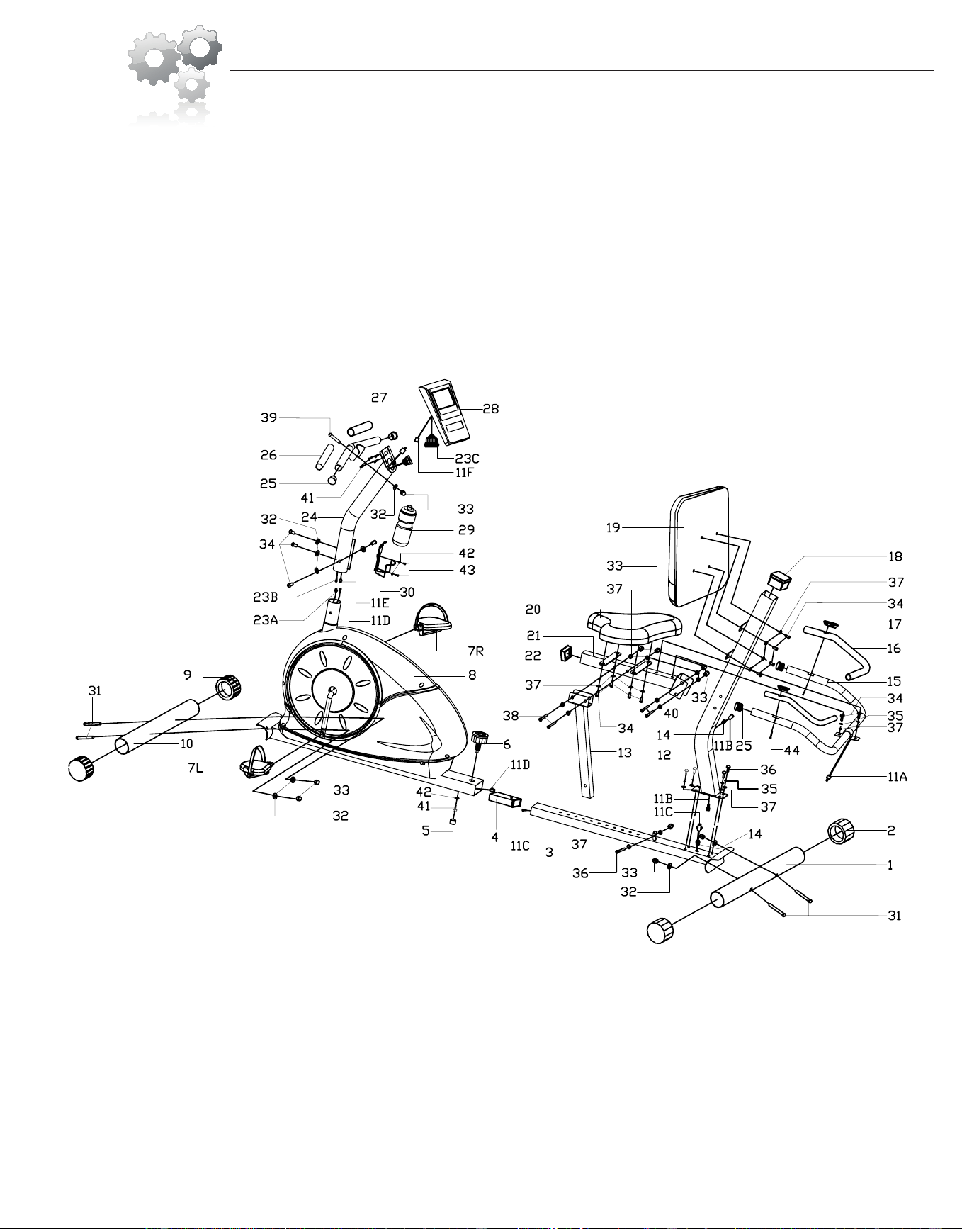
Exploded Diagram
The following diagram is provided to help you familiarize yourself with the parts and
hardware that will be used during the assembly process. Please note that not all of the
parts and hardware you see here will be used while you are assembling the machine
because some of these items are already pre-installed. Please continue to the next
page to begin the assembly process and use this page only as a reference guide for
parts and hardware.
Downloaded from www.ManualsFile.com manuals search engine
BRB 5200 Page 5
Assembly Instructions
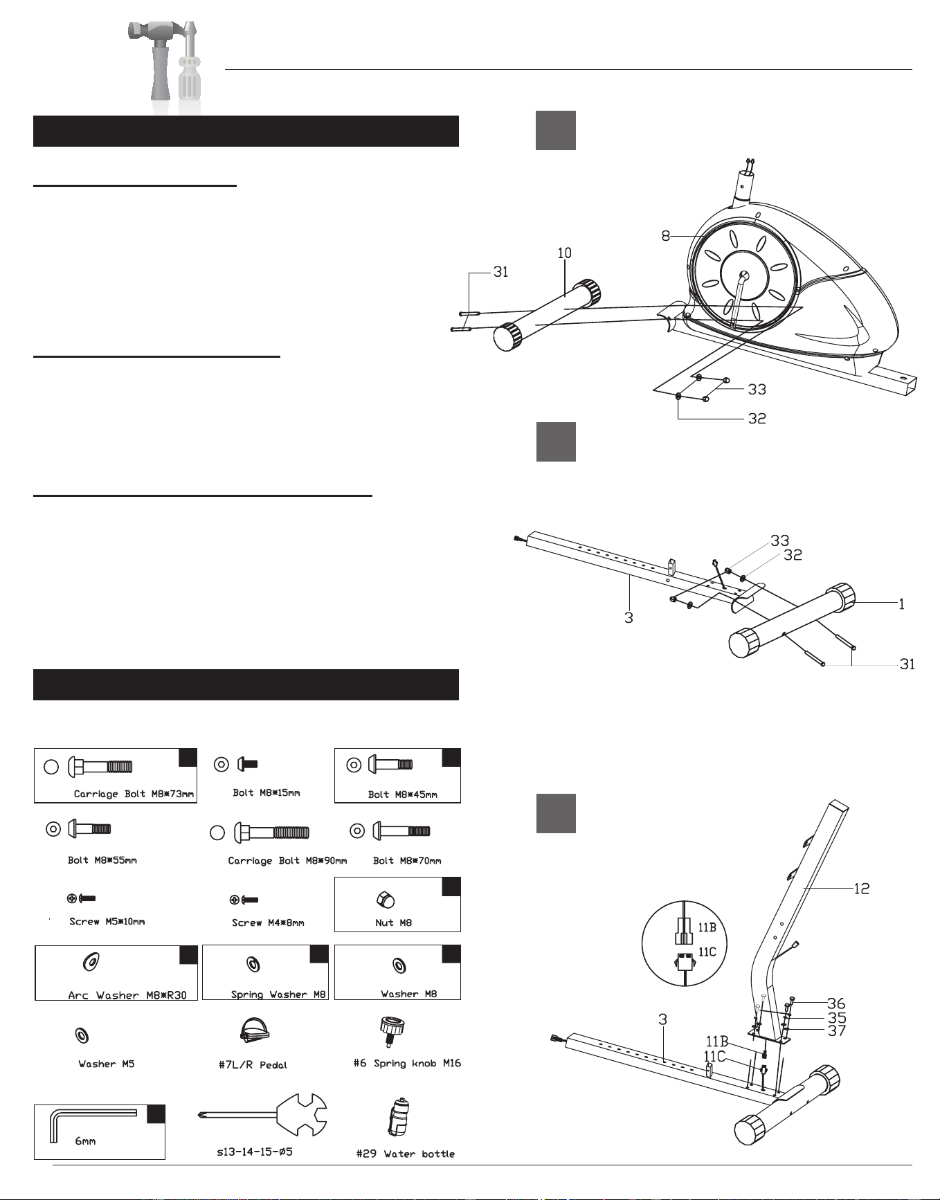
A.) Stabilizer Assembly
Attach the Front stabilizer (#10) to the Main frame
(#8) using two Carriage bolts (#31)[M8 x 73mm],
two Arc washers (#32)[M8 x R30] and two Nuts
(#33)[M8].Please Note, Front Stabilizer (#10) is the
one with end caps that spin.
B.) Bottom Frame Assembly
Attach the Rear stabilizer (#1) to the Bottom
frame (#3) using two Carriage bolts (#31)[M8 x
73mm], two Arc washers (#32)[M8 x R30] and two
Nuts (#33)[M8].
C.) Backrest Cushion Frame Assembly
Connect Sensor wire (#11B) to Sensor wire (#11C).
Attach the previously assembled Bottom frame (#3)
to the Backrest cushion frame (#12) by sliding
four Bolts (#36)[M8 x 45mm] through four Spring
washers (#35)[M8] then through four Washers
(#37)[M8] followed by the Backrest cushion frame
(#12) and then bolted into the Bottom frame (#3).
Hardware Required
A s s e m b l y S t e p 1
C
The diagram below denotes the hardware required to
complete the steps shown on this page.
B
A
4 4
4
4
4
1
4
#31
#34
#36
#38
#39
#40
#41
#43
#33
#32
#35
#37
#42
Downloaded from www.ManualsFile.com manuals search engine
BRB 5200
Assembly Instructions
Page 6
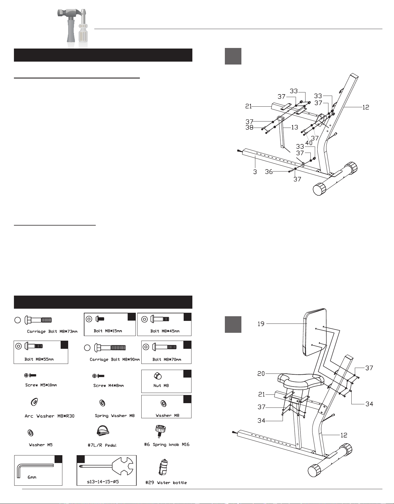
A.) Seat Cushion Frame Assembly
Attach the Seat cushion frame (#21) to the
Backrest cushion frame (#12) using two Bolts
(#40)[M8 x 70], four Washers (#37)[M8] and two Nuts
(#33)[M8]. DO NOT TIGHTEN THE NUTS AND
BOLTS YET. Attach the Seat cushion support
frame (#13) to the Seat cushion frame (#21)
using two Bolts (#38)[M* x 55mm], four Washers
(#37)[M8] and two Nuts (#33)[M8]. DO NOT TIGHTEN
THE NUTS AND BOLTS YET. Connect the Seat
cushion support frame (#13) to the Bottom frame
(#3) using one Bolt (#36)[M8 x 45mm], two Washers
(#37)[M8] and one Nut (#33)[M8]. Tighten all nuts and
bolts at this time.
B.) Cushion Assembly
CAUTION: DO NOT OVERTIGHTEN BOLTS!
Bolt the Backrest cushion (#19) to the Backrest
cushion frame (#12) using a total of four Bolts
(#34)[M8 x 15mm] and four Washers (#37)[M8]. Bolt
the Seat cushion (#20) to the Seat cushion frame
(#21) using a total of four Bolts (#34)[M8 x 15mm] and
four Washers (#37)[M8].
Hardware Required
A s s e m b l y S t e p 2
A
B
5
8
18
1
2 2
11
#31
#34
#36
#38
#39
#40
#41
#43
#33
#32
#35
#37
#42
Downloaded from www.ManualsFile.com manuals search engine
Assembly Instructions
BRB 5200 Page 7
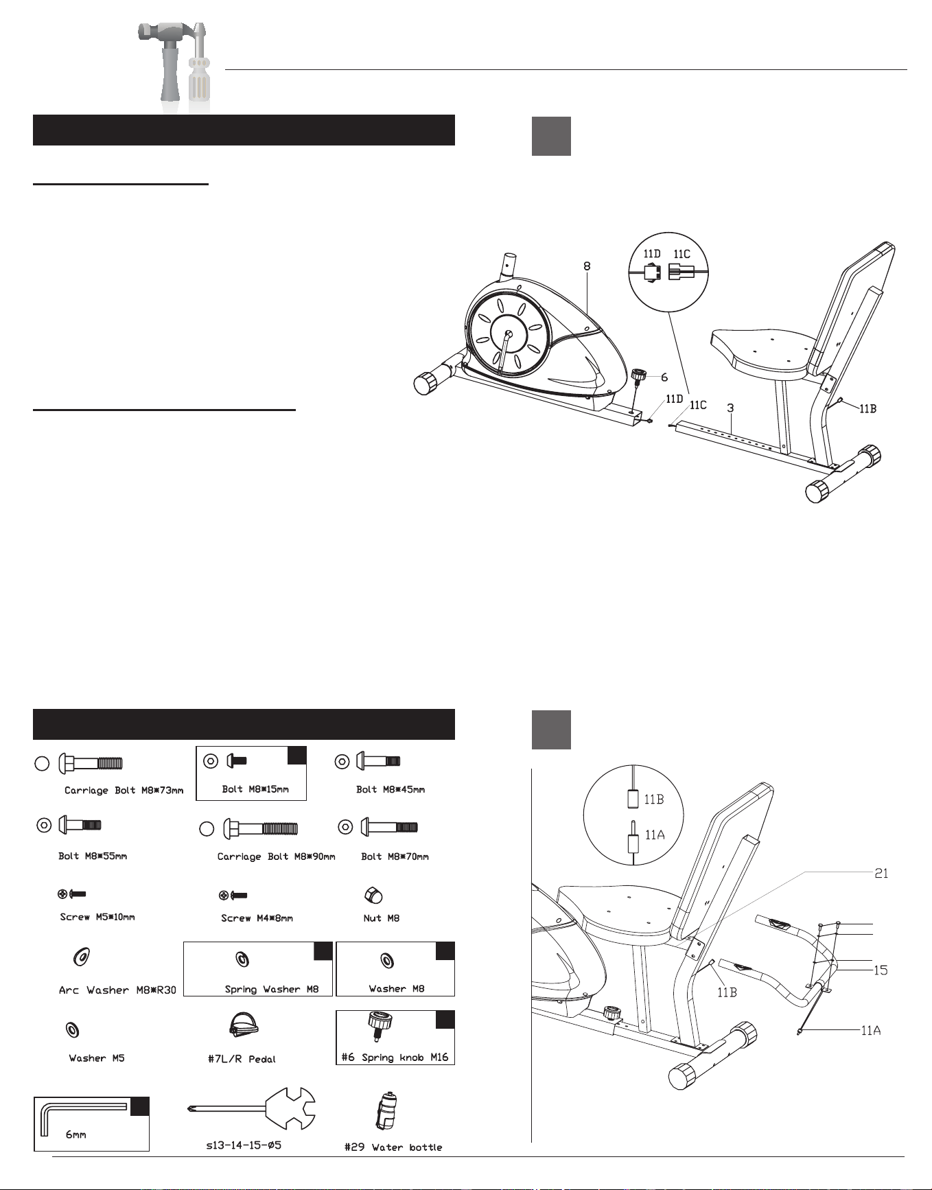
A.) Frame Assembly
Connect Sensor wire (#11C) to Sensor wire (#11D)
and then slide the Bottom frame (#3) into the Main
frame (#8). Slide the Bottom frame (#3) further
into the Main frame (#8) for shorter users and
further out for taller users. Once you select the
desired setting, screw the Spring knob (#6) into
the Main frame (#8) and through the Bottom
frame (#3).
B.) Rear Handle Bar Assembly
Attach the Rear handle bar (#15) to the Seat
cushion frame (#21) using two Bolts (#34)[M8 x
15mm] two Spring Washers (#35)[M8] and two
Washers (#37)[M8]. Connect the Sensor wire
(#11B) to the Sensor wire (#11A).
Hardware Required
A s s e m b l y S t e p 3
A
B
34
35
37
1
1
2
2
#31
#34
#36
#38
#39
#40
#41
#43
#33
#32
#35
#37
#42
2
Downloaded from www.ManualsFile.com manuals search engine
Assembly Instructions
BRB 5200 Page 8
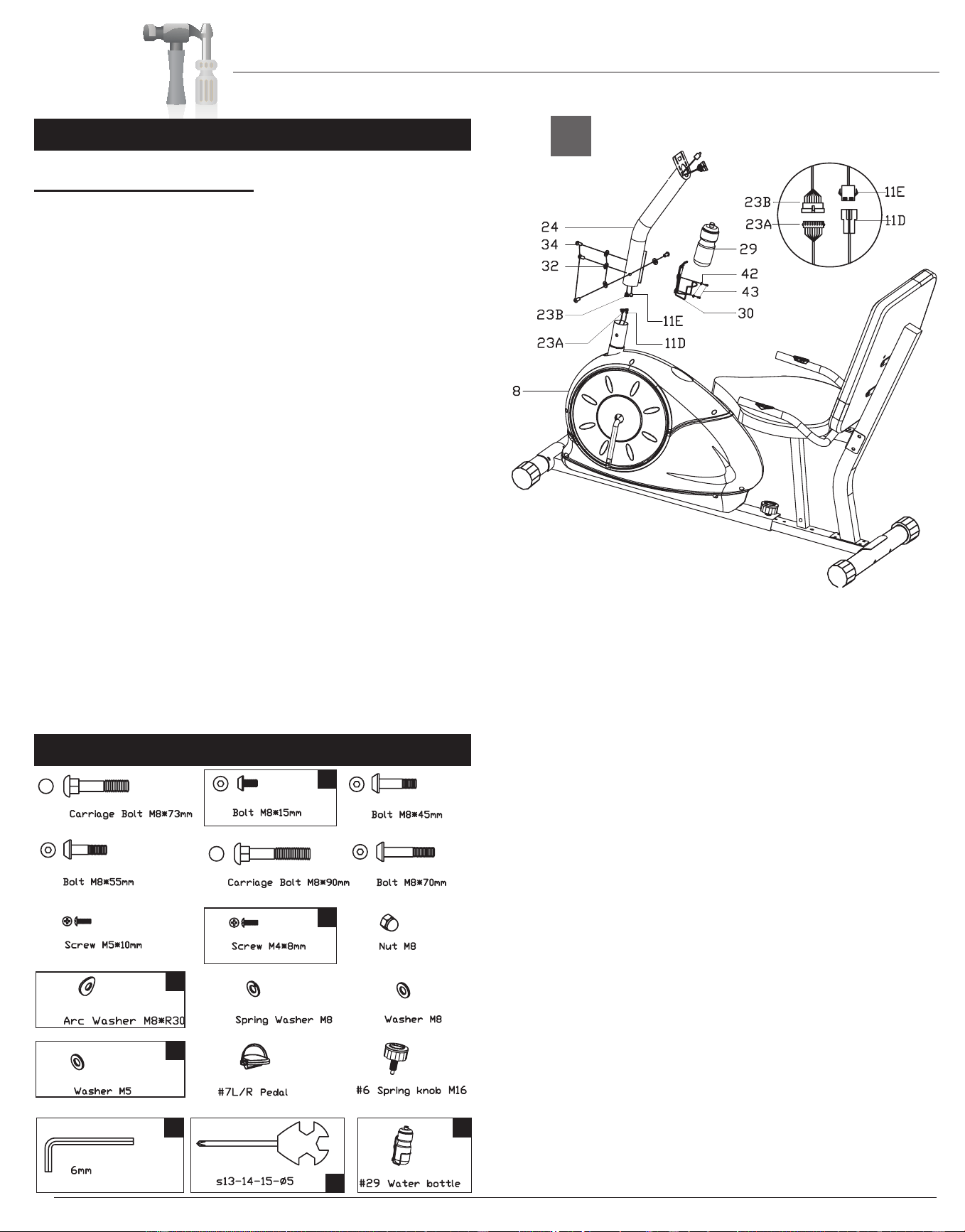
A.) Front Post Assembly
With the help of an assistant, connect the Sensor
wire (#11D) to Sensor wire (#11E) and also
connect Sensor wire (middle) (#23B) to Sensor
wire (lower) (#23A). Slide the Front post (#24)
onto the Main frame (#8) and then secure it using
four Bolts (#34)[M8 x 15mm] and four Arc washers
(#32)[M8 x R30]. Attach the Water bottle holder
(#30) to the Front post (#24) using two Screws (#43)
[M4 x8mm] and two Washers (#42)[M5]. Insert the
Water bottle(#29) into the Water bottle holder(#30).
Hardware Required
A s s e m b l y S t e p 4
A
4
2
4
2
1
1
1
#31
#34
#36
#38
#39
#40
#41
#43
#33
#32
#35
#37
#42
Downloaded from www.ManualsFile.com manuals search engine
Assembly Instructions
BRB 5200 Page 9
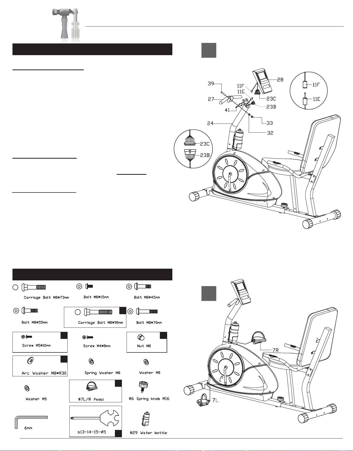
A.) Monitor Assembly
Connect the Sensor wire (upper) (#23C) to the
Sensor wire (middle (#23B) and also connect the
Sensor wire (#11F) to the Sensor wire (#11E).
Use four Screws (#41)[M5 x 10mm] to mount the
Monitor (#28) to the Front post (#24). Attach the
Front handle bar (#27) to the Front post (#24)
using one Carriage bolt (#39)[M8 x 90mm], one Arc
washer (#32)[M8 x R30] and one Nut (#33)[M8].
B.) Pedal Assembly
Screw Right Pedal (#7R) into the right crankshaft
by turning the Right pedal (#7R) clockwise.
Screw in the opposite Left pedal (#7L) by screwing
counterclockwise.
The assembly process is complete. Please ensure
all nuts, bolts and knobs are securely tightened
before using the cycle.
Hardware Required
A s s e m b l y S t e p 5
A
B
#31
#34
#36
#38
#39
#40
#41
#43
#33
#32
#35
#37
#42
2
1
4
1
1
1
Downloaded from www.ManualsFile.com manuals search engine
The monitor is designed for programmable magnetic bikes and introduced with the following categories:
- Key Functions
- About Displays
-
Operating Ranges
- Things You Should Know Before Exercising
- Operation Instructions
z Key Functions
There are total 6 keys including START/STOP, ENTER, MODE, UP, DOWN, and RECOVERY.
A.START/STOP:Starts or stops the program chosen. And, resets the monitor by pressing and holding for 2 seconds.
B.
ENTER : Chooses the functions from PROGRAMS, GENDER, TIME, HEIGHT, WEIGHT, DISTANCE, WATT,
TARGET HEART RATE, AGE, and Resistance Levels. The chosen function shall flash. Please note that not all the
functions can be selected in every program according to the types of each program.
C.
MODE:Changes the displays of the values between RPM or S PEED, and CAL or WATT. The values of RPM and
WATT show at the same time, or the values of SPEED and CAL do by pressing it.
D.UP(▲):Selects or increases the values of PROGRAMS, GENDER, TIME, HEIGHT, WEIGHT. DISTANCE, WATT,
TARGET HEART RATE, AGE, and Resistance Levels.
E. DOWN(▼):Selects or decreases the values of PROGRAMS, GENDER, TIME, HEIGHT, WEIGHT, DISTANCE,
WATT, TARGET HEART RATE, AGE, and Resistance Levels.
F.TEST(RECOVERY):Starts the function of PULSE RECOVERY.
z
About Display
A.
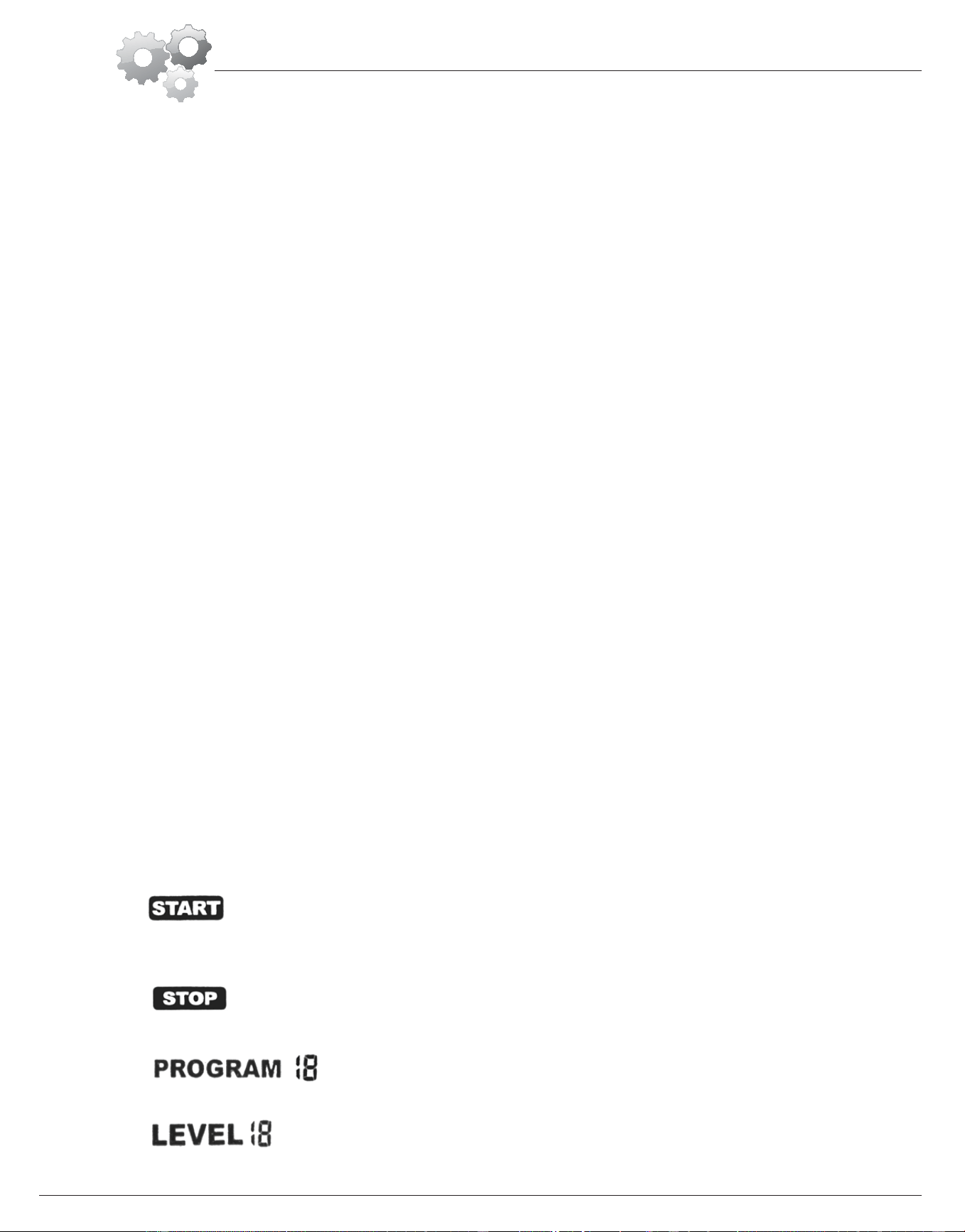
START:Indicates the program selected has started.
B. STOP : Indicates the program selected has stopped. And, users are free to change the programs and the value of
functions applied.
C. PROGRAM n: Indicates the programs selected from PROGRAM 1 to PROGRAM 15 (or 17).
D.LEVEL n: Indicates the level of resistan ce selected from LEVEL 1 to LEVEL 16.
Computer Operation
BRB 5200 Page 10
Downloaded from www.ManualsFile.com manuals search engine
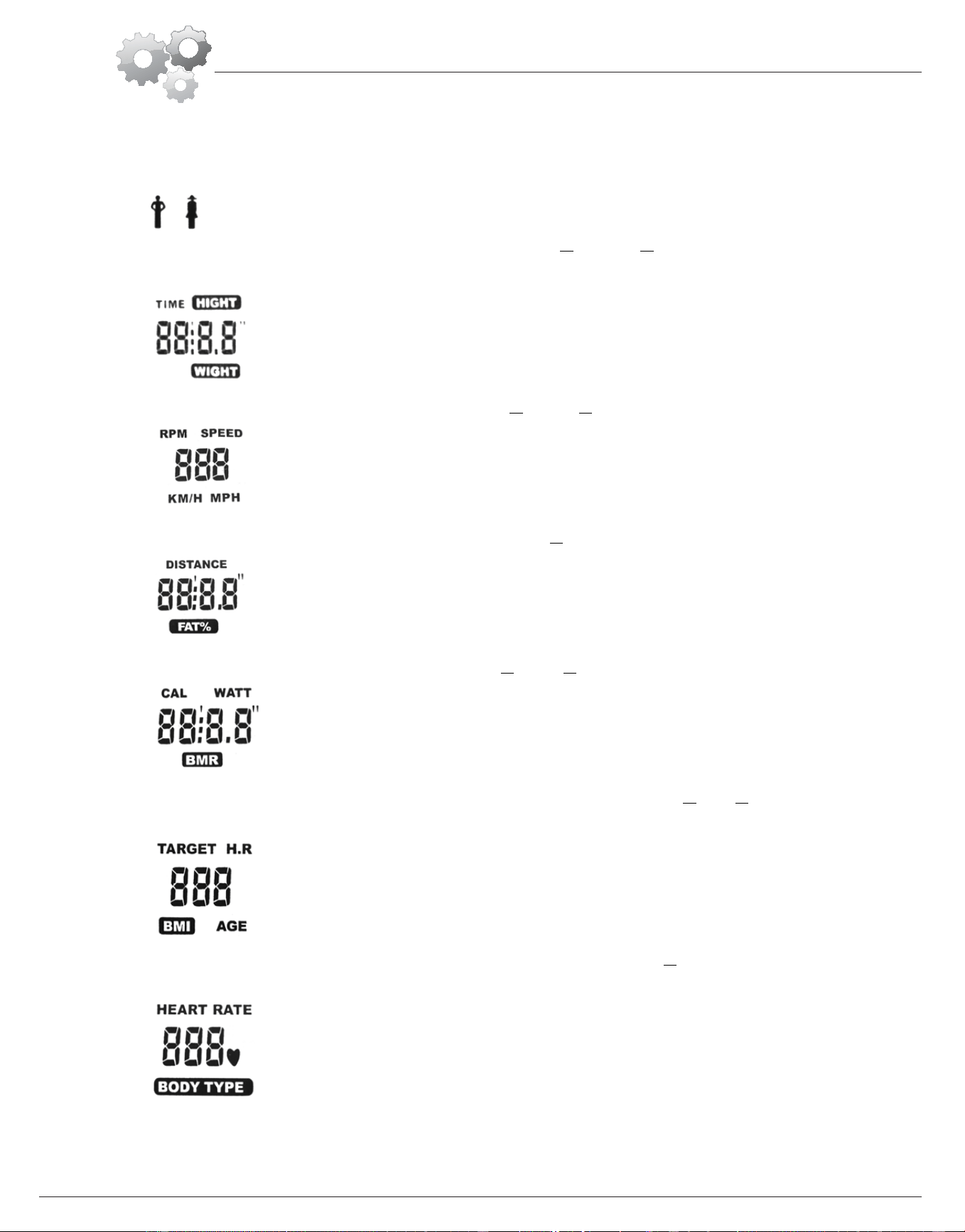
E. GENDER: Indicates the gender (Male or Female) selected.
F. TIME/HEIGHT/WEIGHT Display: Displays the value of TIME or
HEIGHT or WEIGHT displayed depending on the
programs.
G.
RPM/SPEED/MPH Display: Displays the value of RPM or SPEED or MPH depending on the programs.
H.DISTANCE/FAT% Display: Displays the value of DISTANCE or FAT% displayed depending on the programs.
I. CAL/WATT/BMR Display: Displays the value of CAL or WATT or BMR depending on the programs.
J.
TARGET H.R./BMI/AGE Display: Displays the value of TARGET HEART RATE or
BMI or AGE depending on the
programs.
K.HEART RATE/BODY TYPE Display: Display the value of HEART RATE or BODY TYPE depending on the
programs.
Computer Operation
BRB 5200 Page 11
Downloaded from www.ManualsFile.com manuals search engine
L. LOADING (RESISTANCE) Profiles: There are 10 columns of loading bars, and 8 bars in each column. Each column
represents 3 minutes workout (without the change of TIME value),and each bar represents 2 levels of resistance.
z
Operating Ranges
z
Things You Should Know Before Exercising
A.The values calculated or measured by the computer are for exercise purpose only, not for medical purpose.
B. The Variables May Need To Change In The Programs:
Please note that only 1 value of TIME or DISTANCE can be adjusted. You cannot set the value for both TIME and
DISTANCE at the same time. For example, the value of DISTANCE is “0.0” while the value of TIM E is adjusted to be
any number except “00:00”.
C.
Programs Selection:
There are 17 programs and 1 Recovery function (including 1 Manual Program,6 Preset Programs,1 Body Fat
Program,4 Heart Rate Control Programs,4 User Setting Programs,1 WATT Control Program, and 1 Pulse Recovery
Values
Range in
Count up mode
Range in
Count down mode
Preset
Value
Increment or
Decrement
PROGRAM 1~17 17~1 1 1
LEVEL 1~16 16~1 N/A 1
GENDER Male, Female N/A Male N/A
TIME 0:00~99:59 99:00~5:00 0:00 1:00
HEIGHT(cm) 130~200 200~130 175.0 1
WEIGHT(kg) 20~150 150~20 70.0 1
DISTANCE 0.0~999.0 999.0~1.0 0.0 1.0
WATT 40~200 400~20 20 10
TARGET H.R 80~220 220~60 90 1
AGE 10~99 99~10 30 1
Programs Variables
P1~P7 TIME,DISTANCE,AGE
P8 GENDER,HEIGHT,WEIGHT,AGE
P9 TIME,DISTANCE,TARGET H.R.
P10~P12 TIME,DISTANCE,AGE
P13~P16 TIME,DISTANCE,AGE,10 Intervals
P17 TIME,DISTANCE,WATT,AGE
Computer Operation
BRB 5200 Page 12
Downloaded from www.ManualsFile.com manuals search engine
Measuring).
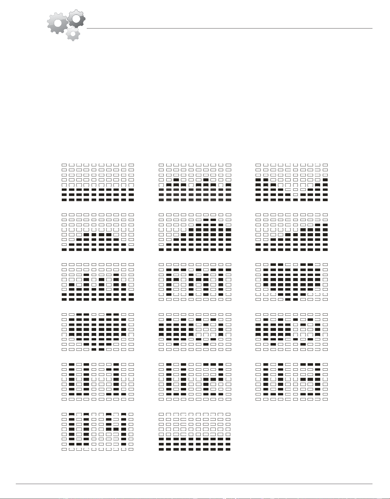
D.
Program Graph:
Each graph shown is the profile of the loading(resistance) in each interval (column). With the value of TIME counting
up, each interval is 3 minutes that all the columns make up 30 minutes. With the value of TIME counting down, each
interval is the value of setup TIME divided by 10. For example, if the time value is setup to 40 minutes, each interval
will be 40 minutes divided by 10 intervals(40/10=4). Then, each interval will be 4 minutes. The following graphs are
all the profiles in the monitor.
Program 1 (Manual) Program 2 (Polling) Program 3 (Valley)
Program 4 (Fat Burn) Program 5 (Ramp) Program 6 (Mountain)
Program 7 (Random) Program 8 (Body Fat) Program 9 (Target H.R.)
Program 10 (60%H.R.C.) Program 11 (70%H.R.C.) Program 12 (85%H.R.C.)
Program 13 (User Setting) Program 14 (User Setting) Program 15 (User Setting)
Program 16 (User Setting) Program 17 (Watt Control)
Computer Operation
BRB 5200 Page 13
Downloaded from www.ManualsFile.com manuals search engine

E. Body Types:
There are 9 body types divided according to the FAT% calculated. Type 1 is from 5%to 9%. Type 2 is from 10% to
14%. Type 3 is from 15% to 19%. Type 4 is from 20% to 24%. Type 5 is from 25% to 29%. Type 6 is from 30% to 34%.
Type 7 is from 35% to 39%. Type 8 is from 40% to 44%. Type 9 is from 45% to 50%.
F.
BMR: Basal Metabolism Ratio
G.BMI: Body Mass Index
z Operation Instructions
After you selected the desired Program, you may press START/STOP to start the exercise. All function data
(TIME,DISTANCE,CAL) start counting up from zero once the training starts. Optionally, you may set value(s) on different
variables for exercising with specific goals.
A.Exercising With a Specific Goal:
1.
TIME Control: Sets up a period of time to e xercise.(Except in Program 8)
2. DISTANCE Control: Sets up a certain distance to exercise. (Except in Program 8)
3. BODY FAT Control: Computer designs various programs for different people with different body fat ratio.
4.
WATT Control: Keeps different bodies burning in desire WATT condition
B.
Pulse Rate:
The whole set of heart rate detector include 2 sensors each side. Each sensor has 2 pieces of metal parts. The correct
way to get detected is to gently hold both metal parts each hand. With the good signals picked up by the computer, the
heart mark in the HEART RATE/BODY TYPE Display shall flash.
C.Manual Program:
PROGRAM 1 is a manual program. Press “ENTER” key to select TIME, DISTANCE, and AGE. Then, press ▲ or ▼
key to adjust the values. The default level of loading is 6.After pressing “START/STOP” key to exercise, please also
apply the heart rate detector appropriately. Users may exercise in any desire level (by pressing▲ or ▼during the
workout) with a period of time or a certain distance. With the input of age, the computer may suggest a target heart rate
to e xercise. The suggested heart rate is 85% (220-age).So, if the heart rate detected equals to or greater than the
TARGET H.R., the value of HEART RATE will keep flashing. Please note that it is a warning for users to slow
down or to lower the level of loading.
D.
Preset Programs:
Program2 to Program7 are the preset programs .Press “ENTER” key to select TIME, DISTANCE, and AGE. Then,
press▲ or ▼ key to adjust the values. Users may exercise with different level of loading in different intervals as the
Computer Operation
BRB 5200 Page 14
Downloaded from www.ManualsFile.com manuals search engine

profiles show. After pressing "START/STOP” key to exercise, please also apply the heart detector appropriately. Users
may also exercise in any desire level (by pressing▲ or ▼during the workout) with a period of time or a certain
distance. With the input of age, the computer may suggest a target heart rate to exercise, The suggested heart rate is
85% (220-age). So, if the heart rate detected equals to or greater than the TARGET H.R., the value of HEART RATE
will keep flashing. Please note that it is a warning for users to slow down or to lower the level of loading.
E. Body Fat Program
Program 8 is a special program designed to calculate users’ body fat ratio and to design a specific loading profile for
users. With 9 different body types, the computer can generate 9 different profiles for each. Press “ENTER” key to
select GENDER, HEIGHT WEIGHT, and AGE. Then, press ▲ or ▼ key to adjust the values. After pressing
“START/STOP” key to calculate body fat, please also apply the heart rare detector appropriately. If the detector cannot
pick up any signals, an error message “E3” will show up in the profile display. If it happens , press “START/STOP”
key to calculate again, Then, the calculation values of FAT%, BMR, BMI, BODY TYPE, and a designed profile will
show up shortly . Press “START/STOP” key to exercise. The profile shown in the display is specially designed for
your body type.
F. Heart Rare Control Programs:
Program 9 to Program12 are the Hears Rate Control Program. In Program9, press “Enter” key to select TIME
DISTANCE, and TARGET H.R. Users may setup a target heart rate to exercise in a period of time or a certain distance.
In program 10 to program12, press “Enter” key to select TIME, DISTANCE, and AGE. Then, press ▲ or ▼ key to
adjust the values. Users may exercise in a period of time or a certain distance with 60% Max Heart Rate in program 10,
75% Max Heart Rate in program 11 ,and 85% Max Heart Rate in program 12 ,After pressing “START/STOP” k ey to
exercise ,please also apply the heart rate detector appropriately. In these programs, the computer will adjust the level of
loading according to the heart rate detected. For example, the level of loading may increase while the heart rate
detected is lower than TARGET H.R. Also, the level of loading may decrease while the heart rate detected is higher
than TARGET H.R. As a result , the user’s heart rate will be adjusted to close the TARGET H.R. in the range of
TARGET H.R.-5 and TARGET H.R. +5.
G. User Setting Programs:
Program13 to Program16 are the user-setting programs. Users are free to edit the values in the order of TIME,
DISTANCE, AGE, and the level of loading in 10 intervals. The values and profiles will be stored in the memory after
setup. After pressing “START/STOP” key to exercise, please also apply the heart rate detector appropriately. Users
may also change the ongoing loading in each interval by pressing ▲ or ▼ key, and they will not change the level of
loading stored in the memory. With the input of age, the computer may suggest a target heart rate to exercise. The
Computer Operation
BRB 5200 Page 15
Downloaded from www.ManualsFile.com manuals search engine

suggested heart rate is 85% (220-age). So, if the heart rate detected equals to or greater than the TARGET H.R., the
value of HEART RATE will keep flashing. Please note that it is a warning for users to slow down or to lower the
level of loading.
H. WATT Control Program:
Program 17 is a Speed Independent program. Press “ENTER” key to select the values of TIME DISTANCE, WATT,
and AGE. Then, press ▲ or ▼ key to adjust the values. After pressing “START/STOP” key to exercise, please also
apply the heart rate detector appropriately. During the exercise, the level of loading is not adjustable. In this
program, computer will adjust the level of loading according to the value of WATT setup. For example, the level of
loading may increase while the speed is too slow. Also the level of loading may decrease while the speed is too fast.
As a result, the calculated value of WATT will close to the value of WATT setup by users. With the
input of age the computer may suggest a target heart rate to exercise. The suggested heart rate is 85%(220-age). So, if
the heart rate detected equals to or greater than the TARGET H.R., the value of HEART RATE will keep flashing.
Please note that it is a warning for users to slow down or to lower the level of loading.
I. Pulse Recovery:
It is a function to check the condition of pulse recovery that is scaled from 1.0 to 6.0 while 1.0 means the best and 6.0
means the worst and the increment is 0.1. In order to get rated correctly, users must test it right after the workout
finished by pressing “RECOVERY” key and then stop exercising. After the key is pressed, please also apply the heart
rate detector appropriately. the test will last for 1 minute and the result will show in the display.
Computer Operation
BRB 5200 Page 16
Downloaded from www.ManualsFile.com manuals search engine