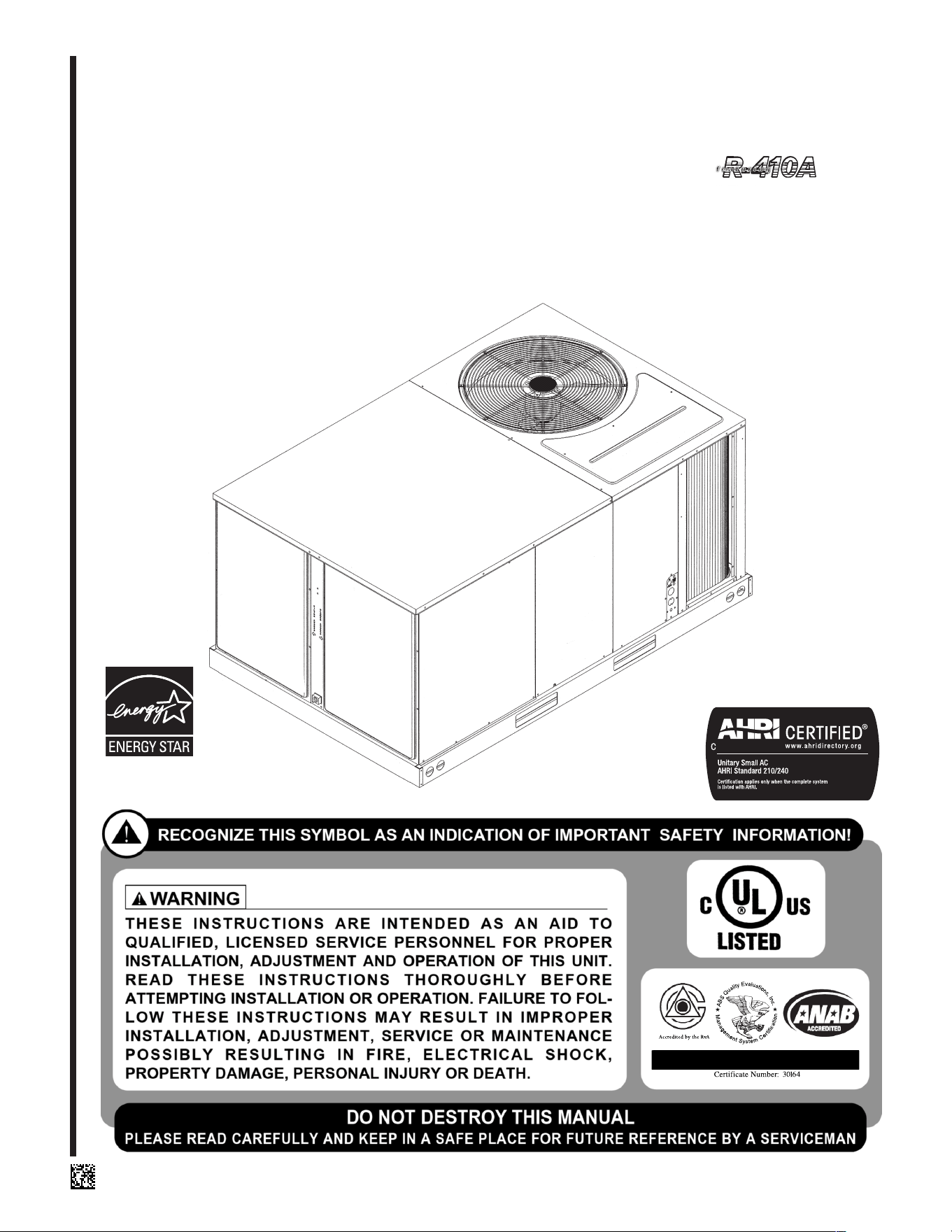
INSTALLATION INSTRUCTIONS
Package Air Conditioners Featuring
Industry Standard R-410A Refrigerant
RLNN 13 SEER (3-5 TONS) SERIES
RLPN 14 SEER (3-5 TONS) SERIES
RLQN 15 SEER (3-5 TONS) SERIES
[ ] INDICATES METRIC CONVERSION
ISO 9001:2000
92-23577-130-02
SUPERSEDES 92-23577-130-01
(14 & 15 SEER
ONLY)
ISO 9001:2008

2
I. TABLE OF CONTENTS
I. Table of Contents ...........................................................................2
I
I. Introduction.....................................................................................3
III. Checking Product Received ...........................................................3
IV. Specifications .................................................................................3
V. Equipment Protection .....................................................................4
Vi. Installation ......................................................................................7
A. General .....................................................................................7
1. Pre-Installation Check Points................................................7
2. Location ................................................................................7
B. Outside Slab Installation ...........................................................7
C. Clearances................................................................................8
D. Rooftop Installation ...................................................................8
VII. Ductwork ........................................................................................9
VIII. Filters............................................................................................10
IX. Conversion Procedure..................................................................10
X. Condensate Drain ........................................................................10
XI. Electrical Wiring............................................................................11
A. Power Wiring ...........................................................................11
B. Special Instructions for Power
Wiring with Aluminum Conductors ..........................................11
C. Control Wiring .........................................................................12
D. Internal Wiring.........................................................................13
E. Grounding ...............................................................................13
F. Thermostat..............................................................................13
XII. Indoor Air Flow Data.....................................................................14
XIII. Units with ECM Blower Motors
(RLQN-A060CV & DV Units Only) ..........................................14
XIV. Crankcase Heat............................................................................17
XV. Pre-Start Check............................................................................17
XVI. Startup..........................................................................................17
XVII. Operation......................................................................................18
XVIII. Auxiliary Heat ...............................................................................18
XIX. General Data...........................................................................19-40
XX. Miscellaneous...............................................................................41
Electrical & Physical Data .......................................................41-49
Airflow Performance................................................................50-59
Heater Kit Characteristics .......................................................60-69
Wiring Diagrams......................................................................70-79
Charge Chart................................................................................80
Troubleshooting............................................................................81
3
II. INTRODUCTION
This booklet contains the installation and operating instructions for your package air con-
ditioner. There are a few precautions that should be taken to derive maximum satisfac-
tion from it. Improper installation can result in unsatisfactory operation or dangerous con-
ditions.
Read this booklet and any instructions packaged with separate equipment required to
make up the system prior to installation. Give this booklet to the owner and explain its
provisions. The owner should retain this booklet for future reference.
III. CHECKING PRODUCT RECEIVED
Upon receiving the unit, inspect it for any damage from shipment. Claims for damage,
either shipping or concealed, should be filed immediately with the shipping company.
C
heck the unit model number, electrical characteristics, and accessories to determine if
they are correct.
IV. SPECIFICATIONS
A. GENERAL
The Packaged Air Conditioner is available without heat or with 6, 10, 12, 15, 20 or 24
kW electric heat. Cooling capacities of 3, 3
1
⁄2 , 4 and 5 nominal tons of cooling are avail-
able. Units are convertible from end supply and return to bottom supply and return by
relocation of supply and return air access panels. See cover installation detail.
The units are weatherized for mounting outside of the building.
The information on the rating plate is in compliance with the FTC and DOE rating for sin-
gle phase units. The following information is for three phase units which are not covered
under the DOE certification program.
1. The efficiency rating of this unit is a product thermal efficiency rating determined
under continuous operating conditions independent of any installed system.
B. MAJOR COMPONENTS
The unit includes a hermetically-sealed refrigerating system (consisting of a compressor,
condenser coil, evaporator coil with thermal expansion valve), a circulation air blower, a
condenser fan, and all necessary internal electrical wiring. The cooling system of these
units is factory-evacuated, charged and performance tested. Refrigerant amount and
type are indicated on rating plate.
C. R-410A REFRIGERANT
All units are factory charged with R-410A refrigerant.
1. Specification of R-410A:
Application: R-410A is not a drop-in replacement for R-22; equipment designs must
accommodate its higher pressures. It cannot be retrofitted into R-22 units.
Pressure: The pressure of R-410A is approximately 60% (1.6 times) greater than
R-22. Recovery and recycle equipment, pumps, hoses and the like need to have design
pressure ratings appropriate for R-410A. Manifold sets need to range up to 800 psig
high-side and 250 psig low-side with a 550 psig low-side retard. Hoses need to have a
service pressure rating of 800 psig. Recovery cylinders need to have a 400 psig service
pressure rating. DOT 4BA400 or DOT BW400.
Combustibility: At pressures above 1 atmosphere, mixture of R-410A and air can
become combustible. R-410A and air should never be mixed in tanks or supply
lines, or be allowed to accumulate in storage tanks. Leak checking should never
be done with a mixture of R-410A and air. Leak checking can be performed safely
with nitrogen or a mixture of R-410A and nitrogen.
2. Quick Reference Guide For R-410A
• R-410A refrigerant operates at approximately 60% higher pressure (1.6 times) than R-
22. Ensure that servicing equipment is designed to operate with R-410A.
• R-410A refrigerant cylinders are pink.
• R-410A, as with other HFC’s is only compatible with POE oils.
• Vacuum pumps will not remove moisture from POE oil.
!
WARNING
PROPOSITION 65: THIS APPLI-
A
NCE CONTAINS FIBERGLASS
INSULATION. RESPIRABLE
PARTICLES OF FIBERGLASS
ARE KNOWN TO THE STATE
OF CALIFORNIA TO CAUSE
CANCER.
.
!
WARNING
THE MANUFACTURER’S WAR-
RANTY DOES NOT COVER ANY
DAMAGE OR DEFECT TO THE
AIR CONDITIONER CAUSED BY
THE ATTACHMENT OR USE OF
ANY COMPONENTS, ACCES-
SORIES OR DEVICES (OTHER
THAN THOSE AUTHORIZED BY
THE MANUFACTURER) INTO,
ONTO OR IN CONJUNCTION
WITH THE AIR CONDITIONER.
YOU SHOULD BE AWARE THAT
THE USE OF UNAUTHORIZED
COMPONENTS, ACCESSORIES
OR DEVICES MAY ADVERSELY
AFFECT THE OPERATION OF
THE AIR CONDITIONER AND
MAY ALSO ENDANGER LIFE
AND PROPERTY. THE MANU-
FACTURER DISCLAIMS ANY
RESPONSIBILITY FOR SUCH
LOSS OR INJURY RESULTING
FROM THE USE OF SUCH
UNAUTHORIZED COMPO-
NENTS, ACCESSORIES OR
DEVICES.
Recognize this symbol as an indi-
cation of Important Safety
Information!
!
4
• R-410A systems are to be charged with liquid refrigerants. Prior to March 1999, R-
410A refrigerant cylinders had a dip tube. These cylinders should be kept upright for
equipment charging. Post March 1999 cylinders do not have a dip tube and should
be inverted to ensure liquid charging of the equipment.
• Do not install a suction line filter drier in the liquid line.
• A liquid line filter drier is standard on every unit.
• Desiccant (drying agent) must be compatible for POE oils and R-410A.
3. Evaporator Coil / TXV
The thermostatic expansion valve is specifically designed to operate with R-410A. DO
NOT use an R-22 TXV. The existing evaporator must be replaced with the factory
specified TXV evaporator specifically designed for R-410A.
4. Tools Required For Installing & Servicing R-410A Models
Manifold Sets:
-Up to 800 PSIG High side
-Up to 250 PSIG Low Side
-550 PSIG Low Side Retard
Manifold Hoses:
-Service Pressure Rating of 800 PSIG
Recovery Cylinders:
-400 PSIG Pressure Rating
-Dept. of Transportation 4BA400 or BW400
V. EQUIPMENT PROTECTION FROM THE
ENVIRONMENT
The metal parts of this unit may be subject to rust or deterioration in adverse environ-
mental conditions. This oxidation could shorten the equipment’s useful life. Salt spray,
fog or mist in seacoast areas, sulphur or chlorine from lawn watering systems, and vari-
ous chemical contaminants from industries such as paper mills and petroleum refineries
are especially corrosive.
If the unit is to be installed in an area where contaminants are likely to be a prob-
lem, special attention should be given to the equipment location and exposure.
1. Avoid having lawn sprinkler heads spray direction on the unit cabinet.
2. In coastal areas, locate the unit on the side of the building away from the waterfront.
3. Shielding provided by a fence or shrubs may give some protection.
Regular maintenance will reduce the buildup of contaminents and help to protect
the unit’s finish.
1. Frequent washing of the cabinet, fan blade and coil with fresh water will remove
most of the salt or other contaminants that build up on the unit.
2. Regular cleaning and waxing of the cabinet with a good automobile polish will pro-
vide some protection.
3. A good liquid cleaner may be used several times a year to remove matter that will
not wash off with water.
Several different types of protective coatings are offered in some areas. These coatings
may provide some benefit, but the effectiveness of such coating materials cannot be ver-
ified by the equipment manufacturer.
The best protection is frequent cleaning, maintenance and minimal exposure to
contaminants.
!
CAUTION
R-410A systems operate at higher pressures than R-22 systems. Do not use
R-22 service equipment or components on R-410A equipment.
!
WARNING
DISCONNECT ALL POWER TO THE UNIT BEFORE STARTING MAINTE-
NANCE. FAILURE TO DO SO CAN RESULT IN SEVERE ELECTRICAL
SHOCK OR DEATH.
5
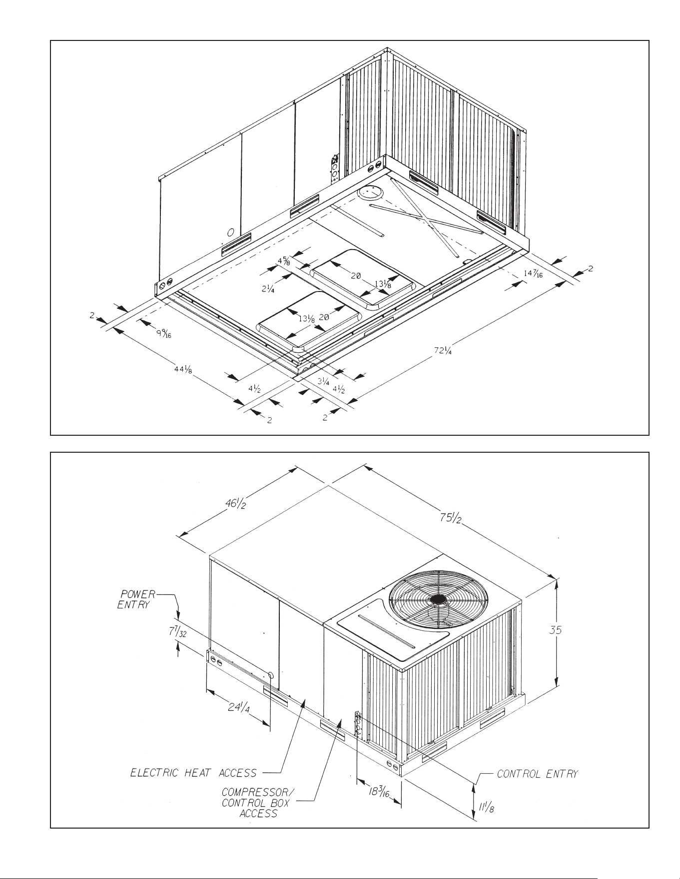
FIGURE 1
UNIT DIMENSIONS
FIGURE 2
UNIT DIMENSIONS
I
LL 1316
ILL1305
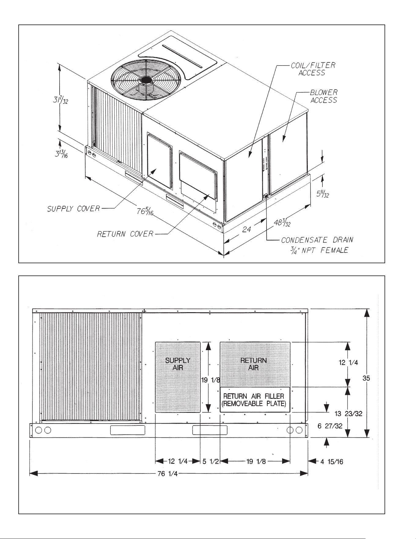
FIGURE 3
UNIT DIMENSIONS
FIGURE 4
UNIT DIMENSIONS
I
LL 1304
ILL 1288
6
VI. INSTALLATION
A. GENERAL
1. PRE-INSTALLATION CHECK-POINTS
Before attempting any installation, the following points should be carefully consid-
ered:
a. Structural strength of supporting members.
(rooftop installation)
b. Clearances and provision for servicing.
c. Power supply and wiring.
d. Air duct connections.
e. Drain facilities and connections.
f. Location for minimum noise.
2. LOCATION
These units are designed for outdoor installations. They can be mounted on a
slab or rooftop. They are not to be installed within any part of a structure such as
an attic, crawl space, closet, or any other place where condenser air flow is
restricted or other than outdoor ambient conditions prevail. Since the application
of the units is of the outdoor type, it is important to consult your local code authori-
ties at the time the first installation is made.
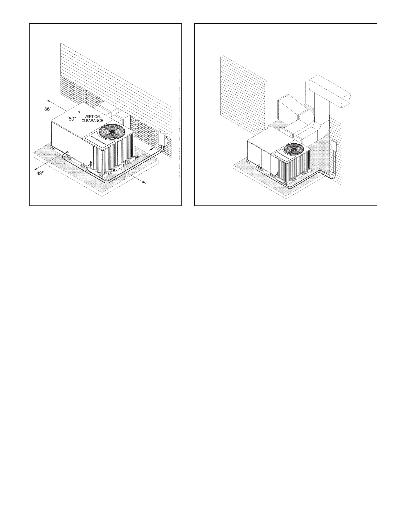
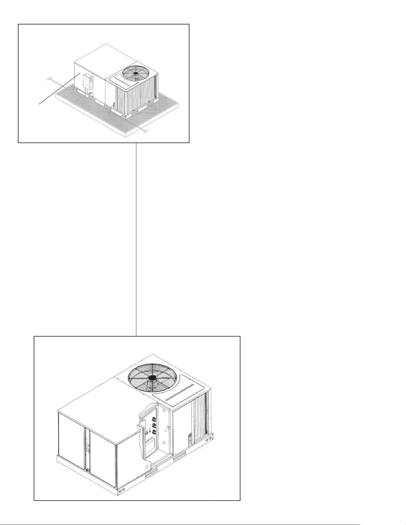
B. OUTSIDE SLAB INSTALLATION
(Typical outdoor slab installations are shown in Figures 5 and 6.)
1. Select a location where external water drainage cannot collect around the unit.
2. Provide a level concrete slab extending 3" beyond all four sides of the unit. The
slab should be sufficient above grade to prevent ground water from entering the
unit. IMPORTANT: To prevent transmission of noise or vibration, slab should not
be connected to building structure.
3. The location of the unit should be such as to provide proper access for inspection
and servicing.
4. Locate unit where operating sounds will not disturb owner or neighbors.
5. Locate unit so roof runoff water does not pour directly on the unit. Provide gutter
or other shielding at roof level. Do not locate unit in an area where excessive
snow drifting may occur or accumulate.
6. Remove compressor shipping supports (if so equipped) after installation.
I
LL I308
FIGURE 5
P
ACKAGE AIR CONDITIONER – OUTSIDE SLAB INSTALLATION,
B
ASEMENT OR CRAWL SPACE DISTRIBUTION SYSTEM
FIGURE 6
PACKAGE AIR CONDITIONER – OUTSIDE SLAB INSTALLATION, CLOSET
DISTRIBUTION SYSTEM. SLAB FLOOR CONSTRUCTION
I
LL I309
18”
12”
*
Allow 57" for
economizer on duct side.
*
7
C. CLEARANCES
The following minimum clearances must be observed for proper unit performance
and serviceability.
1. Provide 48" minimum clearance at the front of the unit. Provide 36" minimum
clearance at the left and right side of the unit for service access.
2. Provide 60" minimum clearance between top of unit and maximum 3 foot over-
hang.
3. Unit is design certified for application on combustible flooring with 0" minimum
clearance.
4. See Figure 5 for illustration of minimum installation-service clearances.
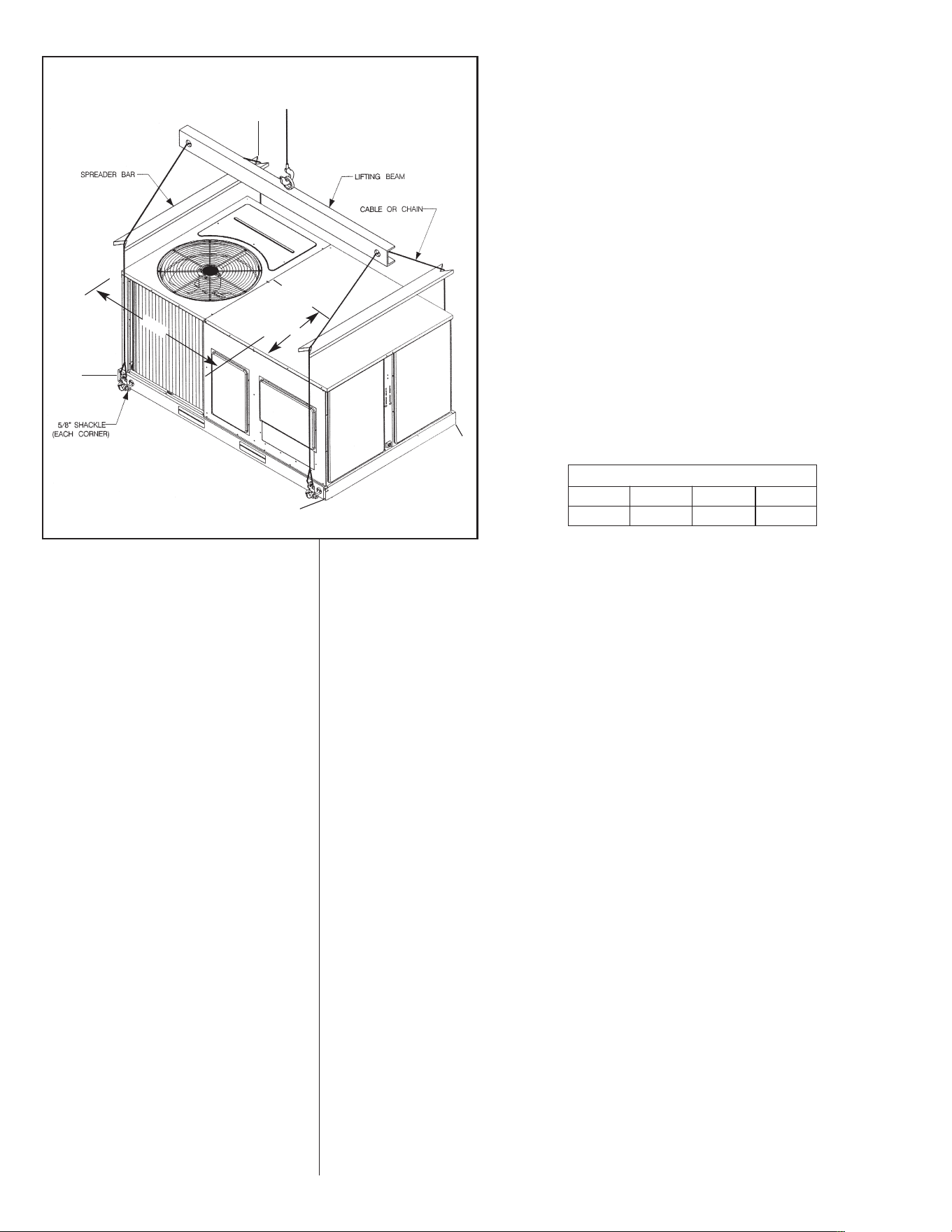
D. ROOFTOP INSTALLATION
1. Before locating the unit on the roof, make sure that the strength of the roof and
beams is adequate at that point to support the weight involved. (See specification
sheet for weight of unit.) This is very important and user’s responsibility.
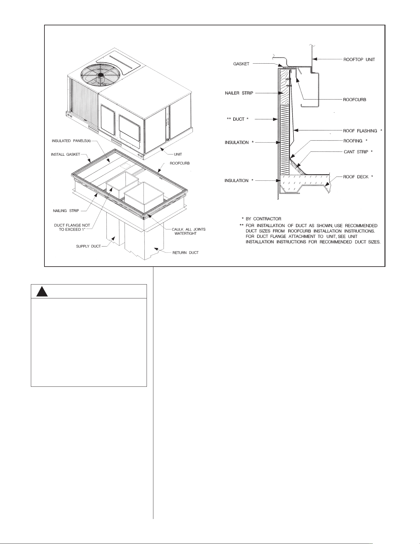
2. For rigging and roofcurb details, see Figures 7 and 8. Use field-furnished spread-
ers.
3. For roofcurb assembly, see Roofcurb Installation Instructions.
4. If the roofcurb is not used, provisions for disposing of condensate water runoff
must be provided.
5. The unit should be placed on a solid and level roofcurb or platform of adequate
strength. See Figure 9.
6. The location of the unit on the roof should be such as to provide proper access for
inspection and servicing.
7. Remove compressor shipping supports (if so equipped) after installation.
IMPORTANT: If unit will not be put into service immediately, cover supply and return
openings to prevent excessive condensation.
I
LL I296
A
B
D
C
3
8
-
1
/
4
CE
NT
E
R
O
F
GRA
V
I
T
Y
25-
3/
4
FIGURE 7
P
ACKAGE AIR CONDITIONER – RIGGING FOR LIFTING
CORNER WEIGHTS BY PERCENTAGE
AB CD
23% 27% 23% 27%
8
VII.DUCTWORK
Ductwork should be fabricated by the installing contractor in accordance with local codes
and NFPA90A. Industry manuals may be used as a guide when sizing and designing the
duct system - contact Air Conditioning Contractors of America, 2800 Shirlington Road,
Suite 300, Arlington, VA 22206, http://www.acca.org.
The unit should be placed as close to the space to be air conditioned as possible allow-
ing clearance dimensions as indicated. Ducts should be run as directly as possible to
supply and return outlets. Use of non-flammable waterproof flexible connectors on both
supply and return connections at the unit to reduce noise transmission is recommended.
It is preferable to install the unit on the roof of the structure if the registers or diffusers
are located on the wall or in the ceiling. A slab installation could be considered when the
registers are low on a wall or in the floor.
On ductwork exposed to outside air conditions of temperature and humidity, use a mini-
mum of 2" of insulation and a vapor barrier. Distribution system in attic, furred space or
crawl space should be insulated with at least 2" of insulation with vapor barrier. One-half
to 1" thickness of insulation is usually sufficient for ductwork inside the air conditioned
space.
Balancing dampers should be provided for each branch duct in the supply system.
Ductwork should be properly supported from the structure.
When installing ductwork, consider the following items:
1. Noncombustible flexible connectors should be used between ductwork and unit to
reduce noise and vibration transmission into the ductwork.
2. When auxiliary heaters are installed, use noncombustible flexible connectors and
clearance to combustible material of 0" for the first 3 feet of discharge duct.
Clearance to unit top and side is 0".
!
WARNING
DO NOT, UNDER ANY CIRCUM-
STANCES, CONNECT RETURN
DUCTWORK TO ANY OTHER HEAT
PRODUCING DEVICE SUCH AS A
FIREPLACE INSERT, STOVE, ETC.
UNAUTHORIZED USE OF SUCH
DEVICES MAY RESULT IN FIRE,
CARBON MONOXIDE POISONING,
EXPLOSION, PROPERTY DAMAGE,
SEVERE PERSONAL INJURY OR
DEATH.
I
LL I300
ILL I301
FIGURE 8
PACKAGE AIR CONDITIONER – ROOFCURB INSTALLATION
9
VIII.FILTERS
This unit is provided with 2 - 25" x 16" x 1" disposable filters. When replacing filters,
ensure they are inserted fully to the back to prevent bypass.
IX. CONVERSION PROCEDURE
DOWNFLOW TO HORIZONTAL
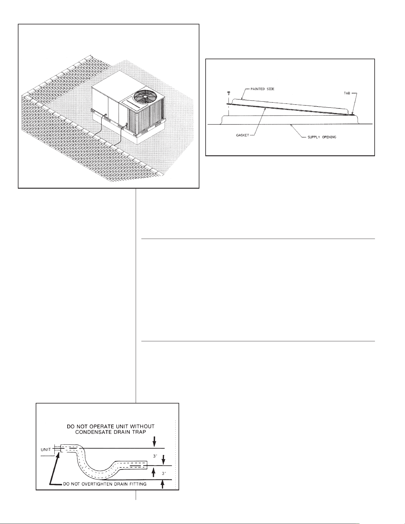
1. Remove the screws and covers from the outside of the supply and return sections.
2. Install the covers in the bottom supply and return openings with the painted side up.
See Figure 10. Use the existing gasket to seal the covers.
3. Secure the supply cover to the base of the unit with 1 screw, engaging prepunched
tab in unit base.
4. Secure the return cover to the base of the unit with screws, engaging prepunched
holes in the unit base.
X. CONDENSATE DRAIN
The condensate drain connection of the evaporator is 3/4" nominal female pipe thread.
IMPORTANT: Install a condensate trap to ensure proper condensate drainage. See
Figure 11.
FIGURE 9
PACKAGE AIR CONDITIONER – FLAT ROOFTOP INSTALLATION, ATTIC OR
D
ROP CEILING DISTRIBUTION SYSTEM. MOUNTED ON ROOFCURB. CURB
M
UST BE LEVEL
I
LL I310
FIGURE 10
C
OVER GASKET DETAIL
ILL I631
FIGURE 11
CONDENSATE DRAIN
10
XI. ELECTRICAL WIRING
Field wiring must comply with the National Electrical Code* and local ordinances that
m
ay apply.
*C.E.C. in Canada
A. POWER WIRING
1. It is important that proper electrical power is available at the unit. Voltage should
not vary more than 10% from that stamped on the unit rating plate. On three
phase units, phases must be balanced within 3%.
2. Install a branch circuit disconnect within sight of the unit and of adequate size to
handle the starting current. Reference Figure 12 for proper location.
3. For branch circuit wiring (main power supply to unit disconnect), the minimum
wire size can be determined from Table A using the circuit ampacity found on the
unit nameplate.
4. This unit incorporates single point electrical connection for unit and electric heat
accessory.
5. Power wiring must be run in grounded rain-tight conduit. Connect the power field
wiring as follows:
a. NO ELECTRIC HEAT - Connect the field wires directly to the contactor pigtail
in the electric heat access area. Connect ground wire to ground lug.
b. WITH ELECTRIC HEAT - Connect the field wires to the terminal block on the
electric heater kit in the electric heat access area. Connect the ground wire to
the ground lug on the heater kit.
NOTE: For field installation of a heater kit, follow the instructions provided with the
heater kit.
6. The pigtail wires in the electric heat access area are factory wired to the contactor
in the control box.
7. DO NOT connect aluminum field wires to electric heat kit power input terminals.
B. SPECIAL INSTRUCTIONS FOR POWER WIRING WITH ALUMINUM
CONDUCTORS
1. Select the equivalent aluminum wire size from the tabulation below:
2.
Attach a length (6" or more) of recommended size copper wire to the unit termi-
nals L1 and L3 for single phase, L1, L2, L3 for three phase.
TABLE B. WIRE SIZES
AWG Copper AWG Aluminum Connector Type and Size
Wire Size Wire Size (or equivalent)
#12 #10 T&B Wire Nut PT2
#10 #8 T&B Wire Nut PT3
#8 #6 Ilsco Split Bolt AK-6
#6 #4 Ilsco Split Bolt AK-4
#4 #2 Ilsco Split Bolt AK-2
#3 #1 Ilsco Split Bolt AK-1/0
#2 #0 Ilsco Split Bolt AK-1/0
#1 #00 Ilsco Split Bolt AK-2/0
#0 #000 Ilsco Split Bolt AK-4/0
COPPER WIRE SIZE — AWG (1% VOLTAGE DROP)
300
250
200
150
100
50
Supply
Wire
Length
Feet
Circuit Ampacity
NOTE:
1. Wire size based on 60ºC type copper conductors below 100 ampacity. 2. Wire size based on 75ºC type copper conductors for 100 ampacity and above.
4
4
6
8
10
14
15
3
4
4
6
8
12
20
2
3
4
6
8
10
25
2
3
4
4
6
1
0
30
1
2
3
4
6
8
35
1/0
1
2
4
6
8
40
1/0
1
2
3
4
6
45
2/0
1/0
1
3
4
6
50
2/0
1/0
1
2
4
6
55
3/0
2/0
1/0
2
3
4
60
3/0
2/0
1/0
1
3
4
65
3/0
2/0
1/0
1
2
4
70
4/0
3/0
2/0
1/0
2
3
75
4/0
3/0
2/0
1/0
2
3
80
4/0
3/0
2/0
1/0
1
3
85
4/0
4/0
3/0
1/0
1
2
90
250
4/0
3/0
2/0
1
2
95
250
4/0
3/0
2/0
1
2
100
250
4/0
3/0
2/0
1
2
105
250
4/0
3/0
2/0
1/0
2
110
300
250
4/0
2/0
1/0
1
115
300
250
4/0
3/0
1/0
1
120
300
250
4/0
3/0
1/0
1
125
300
250
4/0
3/0
1/0
1
130
300
250
4/0
3/0
1/0
1/0
135
350
350
300
4/0
1/0
1/0
140
350
350
300
4/0
2/0
1/0
145
350
350
300
4/0
2/0
1/0
150
350
350
300
4/0
2/0
2/0
155
TABLE A
11
3. Splice copper wire pigtails to aluminum wire with U.L. recognized connectors for
copper-aluminum splices. Follow these instructions very carefully to make a posi-
tive and lasting connection;
a. Strip insulation from aluminum conductor.
b. Coat the stripped end of the aluminum wire with the recommended inhibitor
and wire brush aluminum surface through inhibitor. Inhibitors: Brundy, Pentex
“A”; Alcoa, No. 2EJC; T&B KPOR Shield.
c. Clean and recoat aluminum conductor with inhibitor.
d. Make the splice using the above listed wire nuts or split bolt connectors.
e. Coat the entire connection with inhibitor and wrap with electrical insulating
tape.
WARRANTY MAY NOT APPLY IF CONNECTIONS ARE NOT MADE PER INSTRUC-
TIONS
C. CONTROL WIRING (Class II)
1. Low voltage wiring should not be run in conduit with power wiring.
2. Control wiring is routed through the 7/8" hole adjacent to the compressor access
panel. See Figure 2. Use a minimum #18 AWG thermostat wire. For wire lengths
exceeding 50', use #16 AWG thermostat wire. The low voltage wires are connect-
ed to the unit pigtails which are supplied with the unit in the low voltage connec-
tion box located below the unit control box.
ILL I312
FIGURE 13
HEATER KIT INSTALLATION
FIGURE 12
R
ECOMMENDED LOCATION OF BRANCH CIRCUIT DISCONNECT
TO POWER
BRANCH CIRCUIT DISCONNECT
TO CONTROL
12
3. Figure 14 shows representative low voltage connection diagrams. Read your ther-
mostat installation instructions for any special requirements for your specific ther-
mostat.
NOTE — Units installed in Canada require that an outdoor thermostat (30,000
min. cycles of endurance) be installed and be wired with C.E.C. Class I wiring.
D. INTERNAL WIRING
IMPORTANT: Some single phase models are equipped with a single pole contactor.
Caution must be exercised when servicing as only one leg of the power supply is
broken with the contactor.
Some models are equipped with electronically commutated blower motors which are
constantly energized unless the main unit disconnect is in the off position.
1. A diagram of the internal wiring of this unit is located on the inside of the com-
pressor access panel. If any of the original wire as supplied with the appliance
must be replaced, the wire gauge and insulation must be the same as original
wiring.
E. GROUNDING
F. THERMOSTAT
The thermostat should be mounted on an inside wall about five feet above the floor
in a location where it will not be affected by unconditioned air, sun, or drafts from
open doors or other sources. READ installation instructions in thermostat package
CAREFULLY because each has some different wiring requirements.
FIGURE 14
LOW VOLTAGE CONNECTIONS DIAGRAMS
STANDARD CONTROL WIRING
R
W
G
Y
Y2
C
RED
BLACK
GRAY
YELLOW
ORANGE
BROWN
THERMOSTAT
SUB-BASE
UNIT CONTROLS
WIRE PIGTAILS
NOTE: Y2 IS ONLY USED WITH OPTIONAL ECONOMIZER.
!
WARNING
THE UNIT MUST BE PERMANENTLY GROUNDED. A GROUNDING LUG IS
PROVIDED IN THE ELECTRIC HEAT KIT ACCESS AREA FOR A GROUND
WIRE. FAILURE TO GROUND THIS UNIT CAN RESULT IN FIRE OR ELECTRI-
CAL SHOCK CAUSING PROPERTY DAMAGE, SEVERE PERSONAL INJURY OR
DEATH.
13

XII. INDOOR AIR FLOW DATA
Direct-drive blower models are shipped factory wired for the proper speed at a typical
external static. See Blower Performance Data. Belt-drive blower models have motor
s
heaves set for proper CFM at a typical external static.
XIII. UNITS WITH ECM BLOWER MOTORS
(CV & DV MODELS ONLY)
The ECM (Brushless permanent magnet) motor used on the blower in this product is
pro grammed to operate over a wide range of external static pressures (0.0” - 1.0” W.C.)
with essentially constant air flow (CFM). Motor efficiency on ECM type motors is higher
than that of P.S.C. type motors normally used on this type product. See air flow perfor-
m
ance data tables.
The ECM motor is programmed to provide a “soft” start and stop. On a call for heat or
cool, the motor will gradually ramp up to the field selected CFM speed. This eliminates
the sudden rush of air and noise normally associated with a P.S.C. type motor. Once the
thermostat and blower delay are satisfied, the motor will gradually ramp down as well.
IMPORTANT: Units equipped with ECM motors cannot be used in by-pass zoning
applica tions.
IMPORTANT: The A.C. power plug to the blower motor has locking tabs. It has been
shown that by applying excessive force to the A.C. cable half of the connector it is possi-
ble to force the connector in backwards. It will not seat and “click” properly but will make
connection. If A.C. power is applied with the connector reversed the motor will be imme-
diately destroyed. Do not force power plug into motor connector backwards.
NOTE: Because of the harmonic content of the A.C. Line current to the ECM motor a
conven tional ammeter will not read correct motor amps. Only a true RMS meter will give
accurate AMP readings.
IMPORTANT: The flexibility of ECM motors and the fact that this flexibility is contained
in pro grammed memory, not hardware, emphasizes the need for exact motor numbers
for replace ment motors. Because they all look the same, ECM MOTORS FROM DIF-
FERENT PROD UCTS OR DIFFERENT MODELS OF THE SAME PRODUCT MUST
NOT
BE INTER CHANGED.
IMPORTANT: If an ECM motor is replaced, it is important that the motor be mounted as
the original, as far into the blower wheel as practical for proper motor cooling.
IMPORTANT: The ECM motor is controlled directly from the room thermostat (in all
modes except heating). In cooling, the motor is controlled from the thermostat “Y” termi-
nal. When the “Y” or “R” thermostat circuit is opened a 30 second delay will occur before
the blower motor will cycle. In the heating mode the furnace control board controls the
ECM through the blower relay. When the “W” thermostat circuits are opened, a 90 sec-
ond delay will occur before the blower will cycle off. When the “G” to “R” thermostat cir-
cuit is opened for low speed blower, there is no “off’ delay. All thermostat sub-base com-
binations as recommended and provided through the Parts Department have been test-
ed and are compatible with the ECM motor used in this equipment. Some thermostats
may not be compatible with the ECM motor provided in this unit. With thermostat in off
state, the voltage on control lines “G”, “Y”, or W with respect to 24 vac common should
be less than 3.5 VAC. If the measured voltage is too high, thermostat is incompatible
with the ECM motor and will cause the motor to run when it should be off.
A. ECM MOTOR INTERFACE CONTROL AND SETTINGS
A. (CV & DV UNITS ONLY)
The CV & DV series units use ECM blower motors to deliver a constant level of airflow
over a wide range of external static pressures (up to 1.5” W.C.). The interface board pro-
vides the required communications between the thermostat/IFC and the ECM blower
motor. The inter face board features:
• An automotive-style ATC blade fuse for transformer protection (3 amp).
14
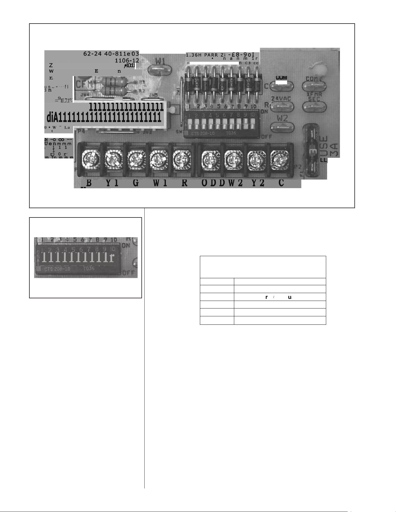
• An on-board LED to indicate blower CFM.
• Inputs for two-stages of cooling: Y1 (first stage) and Y2 (second stage)
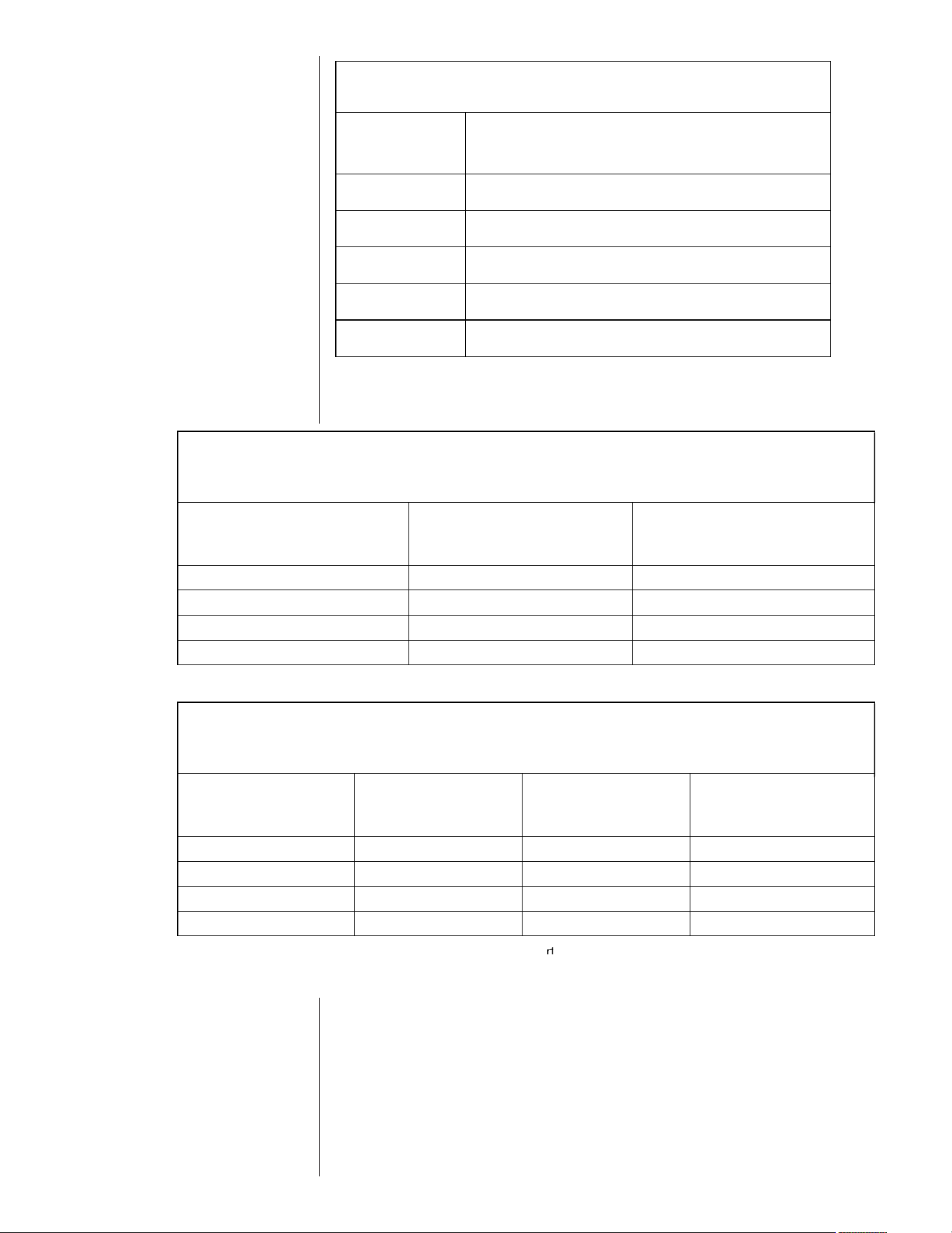
The DIP switches on the interface board are used to define the operation of the
ECM motor (see Table C).
Refer to Figure 16 for switch identification and factory default settings.
IMPORTANT: Disconnect power to unit when changing DIP switch positions. Even if
blower is not operating, the motor will not recognize changes in DIP switch positions
until unit power is removed and then restored.
B. TRANSFORMER PROTECTION
The ECM interface board is equipped with an automotive-style 3 amp ATC blade fuse
for transformer protection. (See Figure 15.) If a short circuit occurs on the secondary
side of the transformer, the fuse will open
C. USING THE ON-BOARD LED TO DETERMINE BLOWER CFM
The ECM interface board LED, which is located in the blower section (see Figure 15),
indi cates blower output by flashing. The LED will pause 1/10 second between each
flash. After the blower CFM has been displayed, the LED will illuminate dimly for 10
seconds before repeating the sequence. (See Table D.)
15
FIGURE 15
ECM INTERFACE BOARD
FIGURE 16
ECM MOTOR SETTINGS
DO NOT WIRE DIRECTLY TO THIS BOARD. THERMOSTAT SHOULD
BE WIRED TO PIGTAILS LOCATED BELOW THE CONTROL BOX.
(THIS BOARD IS LOCATED IN THE BLOWER SECTION)
(This board is located in the blower
section)
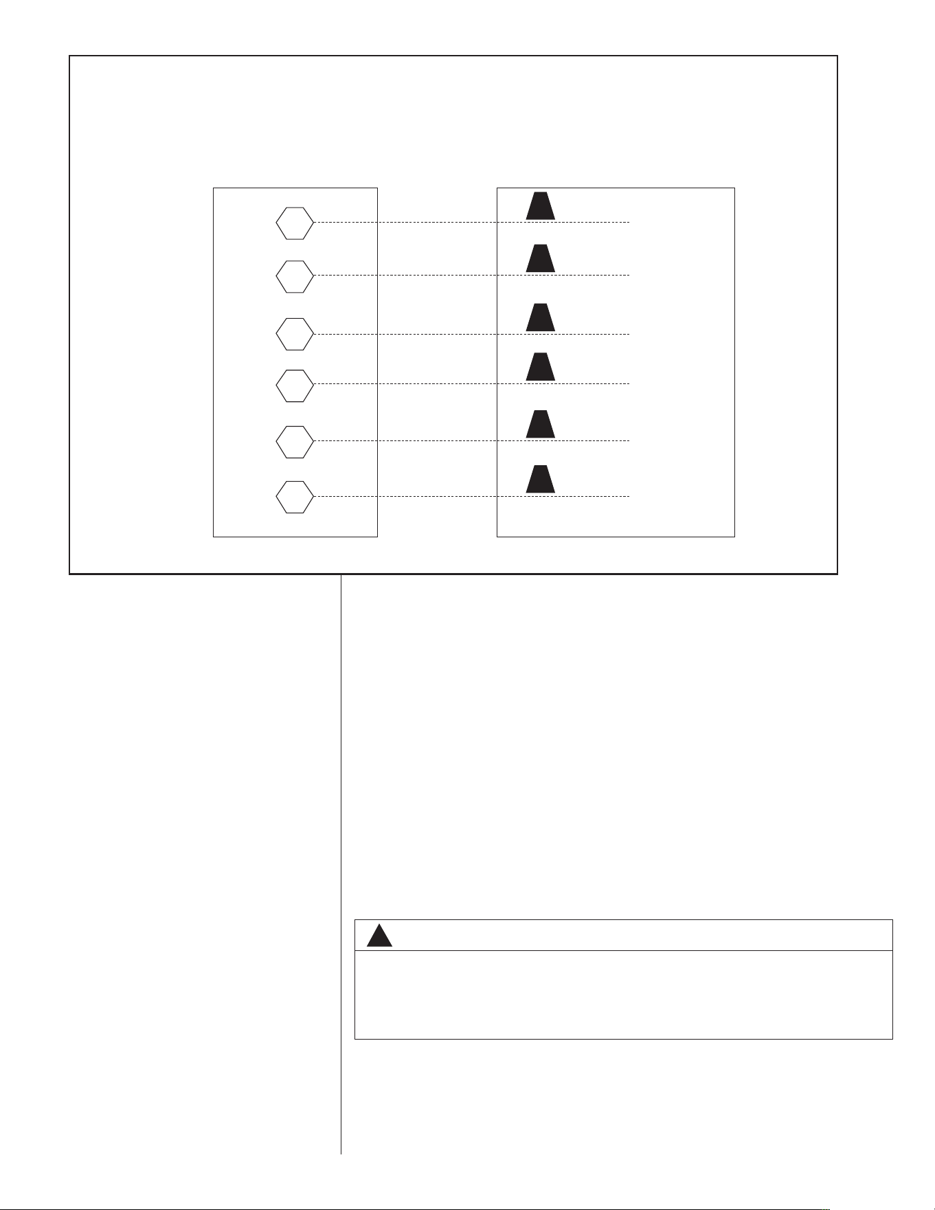
TABLE
7
SWITCH FUNCTIONS
!
Switch
Function
1 &
2
Heating & Fan Airflow Settings
3 &
4
Cooling Airflow Adjustment
5 &
6
Cooling Airflow Settings
7 &
8
Not Used
9 &
10
Not Used
!!
!
!!
!
!!
!
!!
!
!!
!
!!
!
!!
!
!!
!
!!
!
!!
!
!!
!
!!
!
!!
!
!!
!
!!
!
!!
!
!!
!
!!
!
!!
!
!!
!
!!
!
!!
FUNCTITCH ISW
7
E LBTA
hctiSw
&1 2 He
&3 4 Co
&5 6 Co
&7 8 No
!
!!
us
r
NSOFUNCTI
oniFunct
gnitteSw olfrAinaF& gnitaHe
tnemt
s
u
j
Ad
dj
w
o
ow
l
f
r
AigniloCo
sgnittSewolfriAgniloCo
dUstNo
!
!!
sg
!
!!
!
!!
&7 8 No
&9 10 No
i
!
!!
deUstNo
deUstNo
!
!!
!
!!
!
!!
!
!!
!
!!
!
!!
TABLE C
SWITCH FUNCTIONS
16
D. AIRFLOW ADJUSTMENTS
TTAA BB LL EE 88
L
ED FLASH CODES
I
nterface board
D
IP switch
settings
L
ED Output
1400 CFM
• Flashes 14 times
• Illuminate dimly 10 seconds, repeat sequence
1600 CFM
• Flashes 16 times
•
Illuminate dimly 10 seconds, repeat sequence
1800 CFM
• Flashes 18 times
• Illuminate dimly 10 seconds, repeat sequence
2000 CFM
• Flashes 21 times
• Illuminate dimly 10 seconds, repeat sequence
2200 CFM
• Flashes 24 times
• Illuminate dimly 10 seconds, repeat sequence
B
A
T
D
LE
t
eIn
8
E
L
B
S
EDOCHSFLA
d
rao becfarte
t
eIn
D
I
d
rao becfarte
h
ctwisPDI
sgnittse
FMC1400
• 14 hesasFl
• dteainmIllu
FMC1600
• 16 hesasFl
•
teainmIllu di
FMC1800
• 81sehsaFl
• dteainmIllu
FMC2000
• 21 hesasFl
• dteainmIllu
p
ututODLE
esmit14
uqet saepe, rsdnoce s0 1lyim d
esmit16
e
quencsepeatr,ondsecs10 y lmdi
semit
uqet saepe, rsdnoce s0 1lyim d
esmit
uqet saepe, rsdnoce s0 1lyim d
ecne
e
equenc
ecne
ecne
FMC2200
• 24 hesasFl
• dteainmIllu
esmit24
uqet saepe, rsdnoce s0 1lyim d
ecne
TABLE D
LED FLASH CODES
FFIIGGUURREE
3
3
0
0
HEATING AIRFLOW SETTING
CFM
SWITCH 1
POSITION
SWITCH 2
POSITION
1800
OFF
OFF
2000
ON
OFF
2200
OFF
ON
1800
ON
ON
FFIIGGUURREE
3
3
1
1
COOLING AIRFLOW ADJUSTMENT
SELECTION
SWITCH 3
POSITION
SWITCH 4
POSITION
COOLING
AIRFLOW
ADJUSTMENT
A
OFF
OFF
NONE
B
ON
OFF
10%
C
OFF
ON
-10%
D
ON
ON
NONE
Cooling airflow may be adjusted +10% or —10% from nominal airflow using switches 3 & 4. Refer to Figure 33 for
switch positions to achieve the desired adjustments in airflow.
E
R
U
G
I
F
0
3
NG ITAHEGNITTESOWLFRAI
MCF
1800
G
1HCTISW
NOITSIPO
ISW
SIPO
2HCTI
NOITSI
1800
2000
2200
1800
E
R
U
G
I
F
1
3
OWLRFIANG ICOOL TSUJAD
FOF
ON
FOF
ON
TNEMT
OF
OF
ON
ON
FOF
FOF
ON
ON
NOITECSEL
A
B
C
D
detsujdaebyamw olfriagniloCo
rf
3HCTISW
NOITSIPO
FOF
ON
FOF
ON
ro%01+—
f
r
ainalinomomrf10%
4HCTISW
NOITSIPO
AD
FOF
FOF
ON
ON
&3 hesctiwsng iusowlf 4. otrefRe
NGICOOL
WOLFRAI
TENMSTUJAD
NONE
10%
-10%
NONE
rof33erugiFo
detsujdaebyamw olfriagniloCo
ehteveiachots noitsiopchtisw
ro%01+
f
r
rf
ainalinomomrf10%
.wolfrainis tnemstujaddersied
&3 hesctiwsng iusowlf 4. otrefRe
rof33erugiFo
FIGURE 17
H
EATING AIRFLOW SETTING
FIGURE 18
COOLING AIRFLOW ADJUSTMENT
XIV. CRANKCASE HEAT (OPTIONAL)
Crankcase heat is not required on scroll type compressors, but may be necessary for
difficult starting situations.
XV. PRE-START CHECK
1. Is unit properly located and slightly slanted toward indoor condensate drain?
2. Is ductwork insulated, weatherproofed, with proper spacing to combustible materi-
als?
3. Is air free to travel to and from outdoor coil? (See Figure 5.)
4. Is the wiring correct, tight, and according to unit wiring diagram?
5. Is unit grounded?
6. Are field supplied air filters in place and clean?
7. Do the outdoor fan and indoor blower turn freely without rubbing, and are they tight
on the motor shafts?
8. Are the compressor shipping supports removed (if so equipped)?
XVI. STARTUP
1. Turn thermostat to “OFF,” turn “on” power supply at disconnect switch.
2. Turn temperature setting as high as it will go.
3. Turn fan switch to “ON.”
4. Indoor blower should run. Be sure it is running in the right direction.
5. Turn fan switch to “AUTO.” Turn system switch to “COOL” and turn temperature set-
ting below room temperature. Unit should run in cooling mode.
6. Is outdoor fan operating correctly in the right direction?
7. Is compressor running correctly.
8. Check the refrigerant charge using the instructions located on compressor access
panel. Replace service port caps. Service port cores are for system access only and
will leak if not tightly capped.
9. Turn thermostat system switch to proper mode “HEAT” or “COOl” and set thermostat
to proper temperature setting. Record the following after the unit has run some time.
A. Operating Mode _______________________________
B. Discharge Pressure (High)_PSIG
C. Vapor Pressure at Compressor (Low) __________PSIG
D. VaporLine Temperature at Compressor ___________°F.
E. Indoor Dry Bulb______________________________°F.
F. Indoor Wet Bulb _____________________________°F.
G. Outdoor Dry Bulb ____________________________°F.
H. Outdoor Wet Bulb ____________________________°F.
I. Voltage at Contactor ________________________Volts
J. Current at Contactor _______________________Amps
17
F
FIIGGUURREE
3
3
2
2
C
OOLING AIRFLOW SETTING
1
S
T
STAGE COOLING
C
FM
2
N
D
STAGE COOLING
C
FM
SWITCH 5
P
OSITION
SWITCH 6
P
OSITION
1
400
1
800
O
FF
O
FF
1600
2000
ON
OFF
1600
2200
OFF
ON
1
400
1
800
O
N
O
N
E
R
U
G
I
F
2
3
O
WLRFIANG ICOOL GNSETTI
1
S
T
GNILOOCE AGST
M
CF
2
N
D
G
N
D
GNILOOCE AGST
M
CF
5HCTISW
N
OITSIPO
6HCTISW
N
OITSIPO
1
400
1600
1600
1
400
1
800
2000
2200
1
800
F
OF
ON
FOF
O
N
F
OF
FOF
ON
O
N
FIGURE 19
C
OOLING AIRFLOW SETTING
18
K. Model Number_________________________________
L. Serial Number _________________________________
M.Location______________________________________
N. Owner _______________________________________
O. Date_________________________________________
10. Adjust discharge air grilles and balance system.
11. Check ducts for condensation and air leaks.
12. Check unit for tubing and sheet metal rattles.
13. Instruct the owner on operation and maintenance.
14. Leave “INSTALLATION” and ”USE AND CARE“ instructions with owner.
XVII. OPERATION
Most single phase units are operated PSC (no start relay or start capacitor). It is impor-
tant that such systems be off for a minimum of 5 minutes before restarting to allow
equalization of pressures. The thermostat should not be moved to cycle unit without
waiting five minutes. To do so may cause the compressor to stop on an automatic open
overload device or blow a fuse. Poor electrical service can cause nuisance tripping in
overloads or blow fuses.
IMPORTANT: The compressor has an internal overload protector. Under some condi-
tions, it can take up to 2 hours for this overload to reset. Make sure overload has had
time to reset before condemning the compressor.
Some units are equipped with a time delay control (TDC1). The control allows the blower
to operate for up to 60 seconds after the thermostat is satisfied.
XVIII. AUXILIARY HEAT
CONTROL SYSTEM OPERATION
1. In the cooling mode, the thermostat will, on a call for cooling, energize the compres-
sor contactor and the indoor blower relay. The indoor blower can be operated contin-
uously by setting the thermostat fan switch at the “ON” position.
2. In the heating mode, the thermostat will energize one or more supplementary resis-
tance heaters.
!
WARNING
ONLY ELECTRIC HEATER KITS SUPPLIED BY THIS MANUFACTURER AS
DESCRIBED IN THIS PUBLICATION HAVE BEEN DESIGNED, TESTED, AND
EVALUATED BY A NATIONALLY RECOGNIZED SAFETY TESTING AGENCY
FOR USE WITH THIS UNIT. USE OF ANY OTHER MANUFACTURED ELECTRIC
HEATERS INSTALLED WITHIN THIS UNIT MAY CAUSE HAZARDOUS CONDI-
TIONS RESULTING IN PROPERTY DAMAGE, FIRE, BODILY INJURY OR
DEATH.

19
NOTES:
1. Cooling Performance is rated at 95° F ambient, 80° F entering dry bulb, 67° F entering wet bulb. Gross capacity does not include the effect of fan motor heat. AHRI capaci-
ty is net and includes the effect of fan motor heat. Units are suitable for operation to ±20% of nominal cfm. Units are certified in accordance with the Unitary Air Conditioner
Equipment certification program, which is based on AHRI Standard 210/240 or 360.
2. EER and/or SEER are rated at AHRI conditions and in accordance with DOE test procedures.
3. Outdoor Sound Rating shown is tested in accordance with AHRI Standard 270.
XIX. GENERAL DATA - RLNN MODELS
XVII. NOMINAL SIZES 3-5 TONS [10.6-17.6 kW]
% % %
M
odel RLNN- Series A036CK A036CL A036CM A036DK
C
ooling Performance
1
C
ontinued ->
Gross Cooling Capacity Btu [kW] 36,200 [10.61] 36,200 [10.61] 36,200 [10.61] 36,200 [10.61]
EER/SEER
2
1
1.5/13 11.5/13 11.5/13 11.5/13
Nominal CFM/AHRI Rated CFM [L/s] 1200/1250 [566/590] 1200/1250 [566/590] 1200/1250 [566/590] 1200/1250 [566/590]
AHRI Net Cooling Capacity Btu [kW] 34,600 [10.14] 34,600 [10.14] 34,600 [10.14] 34,600 [10.14]
Net Sensible Capacity Btu [kW] 25,300 [7.41] 25,300 [7.41] 25,300 [7.41] 25,300 [7.41]
Net Latent Capacity Btu [kW] 9,300 [2.72] 9,300 [2.72] 9,300 [2.72] 9,300 [2.72]
Net System Power kW 2.93 2.93 2.93 2.93
C
ompressor
No./Type 1/Scroll 1/Scroll 1/Scroll 1/Scroll
Outdoor Sound Rating (dB)
5
7
8787878
Outdoor Coil - Fin Type Louvered Louvered Louvered Louvered
Tube Type MicroChannel MicroChannel MicroChannel MicroChannel
MicroChannel Depth in. [mm] 0.7 [18] 0.7 [18] 0.7 [18] 0.7 [18]
Face Area sq. ft. [sq. m] 13.9 [1.29] 13.9 [1.29] 13.9 [1.29] 13.9 [1.29]
Rows / FPI [FPcm] 1 / 23 [9] 1 / 23 [9] 1 / 23 [9] 1 / 23 [9]
Indoor Coil - Fin Type Louvered Louvered Louvered Louvered
Tube Type MicroChannel MicroChannel MicroChannel MicroChannel
MicroChannel Depth in. [mm] 1 [25] 1 [25] 1 [25] 1 [25]
Face Area sq. ft. [sq. m] 4.8 [0.45] 4.8 [0.45] 4.8 [0.45] 4.8 [0.45]
Rows / FPI [FPcm] 1 / 20 [8] 1 / 20 [8] 1 / 20 [8] 1 / 20 [8]
Refrigerant Control TX Valves TX Valves TX Valves TX Valves
Drain Connection No./Size in. [mm] 1/0.75 [19.05] 1/0.75 [19.05] 1/0.75 [19.05] 1/0.75 [19.05]
Outdoor Fan - Type Propeller Propeller Propeller Propeller
No. Used/Diameter in. [mm] 1/24 [609.6] 1/24 [609.6] 1/24 [609.6] 1/24 [609.6]
Drive Type/No. Speeds Direct/1 Direct/1 Direct/1 Direct/1
CFM [L/s] 3680 [1737] 3680 [1737] 3680 [1737] 3680 [1737]
No. Motors/HP 1 at 1/3 HP 1 at 1/3 HP 1 at 1/3 HP 1 at 1/3 HP
Motor RPM 1075 1075 1075 1075
Indoor Fan - Type FC Centrifugal FC Centrifugal FC Centrifugal FC Centrifugal
No. Used/Diameter in. [mm] 1/10x10 [254x254] 1/10x10 [254x254] 1/10x10 [254x254] 1/10x10 [254x254]
Drive Type Direct Direct Belt (Adjustable) Direct
No. Speeds Multiple Multiple Single Multiple
No. Motors 1 1 1 1
Motor HP 1/2 1/2 1/2 1/2
Motor RPM 1075 1075 1725 1075
Motor Frame Size 48 48 56 48
Filter - Type Disposable Disposable Disposable Disposable
Furnished Yes Yes Yes Yes
(NO.) Size Recommended in. [mm x mm x mm] (1)1x16x25 [25x406x635] (1)1x16x25 [25x406x635] (1)1x16x25 [25x406x635] (1)1x16x25 [25x406x635]
(1)1x16x25 [25x406x635] (1)1x16x25 [25x406x635] (1)1x16x25 [25x406x635] (1)1x16x25 [25x406x635]
Refrigerant Charge Oz. [g] 54 [1531] 54 [1531] 54 [1531] 54 [1531]
Weights
Net Weight lbs. [kg] 453 [206] 471 [214] 471 [214] 453 [206]
Ship Weight lbs. [kg] 460 [209] 478 [217] 478 [217] 460 [209]
Continued ->
20
GENERAL DATA - RLNN MODELS
NOMINAL SIZES 3-5 TONS [10.6-17.6 kW]
NOTES:
1. Cooling Performance is rated at 95° F ambient, 80° F entering dry bulb, 67° F entering wet bulb. Gross capacity does not include the effect of fan motor heat. AHRI capaci-
ty is net and includes the effect of fan motor heat. Units are suitable for operation to ±20% of nominal cfm. Units are certified in accordance with the Unitary Air Conditioner
Equipment certification program, which is based on AHRI Standard 210/240 or 360.
2. EER and/or SEER are rated at AHRI conditions and in accordance with DOE test procedures.
3. Outdoor Sound Rating shown is tested in accordance with AHRI Standard 270.
% % %
M
odel RLNN- Series A036DL A036DM A036JK A036YL
C
ooling Performance
1
C
ontinued ->
Gross Cooling Capacity Btu [kW] 36,200 [10.61] 36,200 [10.61] 36,200 [10.61] 36,200 [10.61]
EER/SEER
2
1
1.5/13 11.5/13 11.5/13 11.5/13
Nominal CFM/AHRI Rated CFM [L/s] 1200/1250 [566/590] 1200/1250 [566/590] 1200/1250 [566/590] 1200/1250 [566/590]
AHRI Net Cooling Capacity Btu [kW] 34,600 [10.14] 34,600 [10.14] 34,600 [10.14] 34,600 [10.14]
Net Sensible Capacity Btu [kW] 25,300 [7.41] 25,300 [7.41] 25,300 [7.41] 25,300 [7.41]
Net Latent Capacity Btu [kW] 9,300 [2.72] 9,300 [2.72] 9,300 [2.72] 9,300 [2.72]
Net System Power kW 2.93 2.93 2.93 2.93
C
ompressor
No./Type 1/Scroll 1/Scroll 1/Scroll 1/Scroll
Outdoor Sound Rating (dB)
5
7
8787878
Outdoor Coil - Fin Type Louvered Louvered Louvered Louvered
Tube Type MicroChannel MicroChannel MicroChannel MicroChannel
MicroChannel Depth in. [mm] 0.7 [18] 0.7 [18] 0.7 [18] 0.7 [18]
Face Area sq. ft. [sq. m] 13.9 [1.29] 13.9 [1.29] 13.9 [1.29] 13.9 [1.29]
Rows / FPI [FPcm] 1 / 23 [9] 1 / 23 [9] 1 / 23 [9] 1 / 23 [9]
Indoor Coil - Fin Type Louvered Louvered Louvered Louvered
Tube Type MicroChannel MicroChannel MicroChannel MicroChannel
MicroChannel Depth in. [mm] 1 [25] 1 [25] 1 [25] 1 [25]
Face Area sq. ft. [sq. m] 4.8 [0.45] 4.8 [0.45] 4.8 [0.45] 4.8 [0.45]
Rows / FPI [FPcm] 1 / 20 [8] 1 / 20 [8] 1 / 20 [8] 1 / 20 [8]
Refrigerant Control TX Valves TX Valves TX Valves TX Valves
Drain Connection No./Size in. [mm] 1/0.75 [19.05] 1/0.75 [19.05] 1/0.75 [19.05] 1/0.75 [19.05]
Outdoor Fan - Type Propeller Propeller Propeller Propeller
No. Used/Diameter in. [mm] 1/24 [609.6] 1/24 [609.6] 1/24 [609.6] 1/24 [609.6]
Drive Type/No. Speeds Direct/1 Direct/1 Direct/1 Direct/1
CFM [L/s] 3680 [1737] 3680 [1737] 3680 [1737] 3680 [1737]
No. Motors/HP 1 at 1/3 HP 1 at 1/3 HP 1 at 1/3 HP 1 at 1/3 HP
Motor RPM 1075 1075 1075 1075
Indoor Fan - Type FC Centrifugal FC Centrifugal FC Centrifugal FC Centrifugal
No. Used/Diameter in. [mm] 1/10x10 [254x254] 1/10x10 [254x254] 1/10x10 [254x254] 1/10x10 [254x254]
Drive Type Belt (Adjustable) Belt (Adjustable) Direct Belt (Adjustable)
No. Speeds Single Single Multiple Single
No. Motors 1 1 1 1
Motor HP 1/2 1/2 1/2 3/4
Motor RPM 1725 1725 1075 1725
Motor Frame Size 48 56 48 56
Filter - Type Disposable Disposable Disposable Disposable
Furnished Yes Yes Yes Yes
(NO.) Size Recommended in. [mm x mm x mm] (1)1x16x25 [25x406x635] (1)1x16x25 [25x406x635] (1)1x16x25 [25x406x635] (1)1x16x25 [25x406x635]
(1)1x16x25 [25x406x635] (1)1x16x25 [25x406x635] (1)1x16x25 [25x406x635] (1)1x16x25 [25x406x635]
Refrigerant Charge Oz. [g] 54 [1531] 54 [1531] 54 [1531] 54 [1531]
Weights
Net Weight lbs. [kg] 471 [214] 471 [214] 453 [206] 471 [214]
Ship Weight lbs. [kg] 478 [217] 478 [217] 460 [209] 478 [217]
C
ontinued ->

21
GENERAL DATA - RLNN MODELS
NOMINAL SIZES 3-5 TONS [10.6-17.6 kW]
NOTES:
1. Cooling Performance is rated at 95° F ambient, 80° F entering dry bulb, 67° F entering wet bulb. Gross capacity does not include the effect of fan motor heat. AHRI capaci-
ty is net and includes the effect of fan motor heat. Units are suitable for operation to ±20% of nominal cfm. Units are certified in accordance with the Unitary Air Conditioner
Equipment certification program, which is based on AHRI Standard 210/240 or 360.
2. EER and/or SEER are rated at AHRI conditions and in accordance with DOE test procedures.
3. Outdoor Sound Rating shown is tested in accordance with AHRI Standard 270.
% % %
M
odel RLNN- Series A036YM A048CK A048CL A048CM
C
ooling Performance
1
C
ontinued ->
Gross Cooling Capacity Btu [kW] 36,200 [10.61] 48,000 [14.06] 48,000 [14.06] 48,000 [14.06]
EER/SEER
2
1
1.5/13 11.5/13 11.5/13 11.5/13
Nominal CFM/AHRI Rated CFM [L/s] 1200/1250 [566/590] 1600/1500 [755/708] 1600/1500 [755/708] 1600/1500 [755/708]
AHRI Net Cooling Capacity Btu [kW] 34,600 [10.14] 46,000 [13.48] 46,000 [13.48] 46,000 [13.48]
Net Sensible Capacity Btu [kW] 25,300 [7.41] 34,000 [9.96] 34,000 [9.96] 34,000 [9.96]
Net Latent Capacity Btu [kW] 9,300 [2.72] 12,000 [3.52] 12,000 [3.52] 12,000 [3.52]
Net System Power kW 2.93 3.93 3.93 3.93
C
ompressor
No./Type 1/Scroll 1/Scroll 1/Scroll 1/Scroll
Outdoor Sound Rating (dB)
5
7
8787878
Outdoor Coil - Fin Type Louvered Louvered Louvered Louvered
Tube Type MicroChannel MicroChannel MicroChannel MicroChannel
MicroChannel Depth in. [mm] 0.7 [18] 0.7 [18] 0.7 [18] 0.7 [18]
Face Area sq. ft. [sq. m] 13.9 [1.29] 16.4 [1.52] 16.4 [1.52] 16.4 [1.52]
Rows / FPI [FPcm] 1 / 23 [9] 1 / 23 [9] 1 / 23 [9] 1 / 23 [9]
Indoor Coil - Fin Type Louvered Louvered Louvered Louvered
Tube Type MicroChannel MicroChannel MicroChannel MicroChannel
MicroChannel Depth in. [mm] 1 [25] 1.3 [32] 1.3 [32] 1.3 [32]
Face Area sq. ft. [sq. m] 4.8 [0.45] 4.8 [0.45] 4.8 [0.45] 4.8 [0.45]
Rows / FPI [FPcm] 1 / 20 [8] 1 / 20 [8] 1 / 20 [8] 1 / 20 [8]
Refrigerant Control TX Valves TX Valves TX Valves TX Valves
Drain Connection No./Size in. [mm] 1/0.75 [19.05] 1/0.75 [19.05] 1/0.75 [19.05] 1/0.75 [19.05]
Outdoor Fan - Type Propeller Propeller Propeller Propeller
No. Used/Diameter in. [mm] 1/24 [609.6] 1/24 [609.6] 1/24 [609.6] 1/24 [609.6]
Drive Type/No. Speeds Direct/1 Direct/1 Direct/1 Direct/1
CFM [L/s] 3680 [1737] 3680 [1737] 3680 [1737] 3680 [1737]
No. Motors/HP 1 at 1/3 HP 1 at 1/3 HP 1 at 1/3 HP 1 at 1/3 HP
Motor RPM 1075 1075 1075 1075
Indoor Fan - Type FC Centrifugal FC Centrifugal FC Centrifugal FC Centrifugal
No. Used/Diameter in. [mm] 1/10x10 [254x254] 1/10x10 [254x254] 1/10x10 [254x254] 1/10x10 [254x254]
Drive Type Belt (Adjustable) Direct Belt (Adjustable) Belt (Adjustable)
No. Speeds Single Multiple Single Single
No. Motors 1 1 1 1
Motor HP 3/4 1/2 1/2 3/4
Motor RPM 1725 1075 1725 1725
Motor Frame Size 56 48 48 56
Filter - Type Disposable Disposable Disposable Disposable
Furnished Yes Yes Yes Yes
(NO.) Size Recommended in. [mm x mm x mm] (1)1x16x25 [25x406x635] (1)1x16x25 [25x406x635] (1)1x16x25 [25x406x635] (1)1x16x25 [25x406x635]
(1)1x16x25 [25x406x635] (1)1x16x25 [25x406x635] (1)1x16x25 [25x406x635] (1)1x16x25 [25x406x635]
Refrigerant Charge Oz. [g] 54 [1531] 68 [1928] 68 [1928] 68 [1928]
Weights
Net Weight lbs. [kg] 471 [214] 477 [216] 495 [225] 496 [225]
Ship Weight lbs. [kg] 478 [217] 484 [220] 502 [228] 503 [228]
[ ] Designates Metric Conversions
C
ontinued ->

22
GENERAL DATA - RLNN MODELS
NOMINAL SIZES 3-5 TONS [10.6-17.6 kW]
NOTES:
1. Cooling Performance is rated at 95° F ambient, 80° F entering dry bulb, 67° F entering wet bulb. Gross capacity does not include the effect of fan motor heat. AHRI capaci-
ty is net and includes the effect of fan motor heat. Units are suitable for operation to ±20% of nominal cfm. Units are certified in accordance with the Unitary Air Conditioner
Equipment certification program, which is based on AHRI Standard 210/240 or 360.
2. EER and/or SEER are rated at AHRI conditions and in accordance with DOE test procedures.
3. Outdoor Sound Rating shown is tested in accordance with AHRI Standard 270.
% % %
M
odel RLNN- Series A048DK A048DL A048DM A048JK
C
ooling Performance
1
C
ontinued ->
Gross Cooling Capacity Btu [kW] 48,000 [14.06] 48,000 [14.06] 48,000 [14.06] 48,000 [14.06]
EER/SEER
2
1
1.5/13 11.5/13 11.5/13 11.5/13
Nominal CFM/AHRI Rated CFM [L/s] 1600/1500 [755/708] 1600/1500 [755/708] 1600/1500 [755/708] 1600/1500 [755/708]
AHRI Net Cooling Capacity Btu [kW] 46,000 [13.48] 46,000 [13.48] 46,000 [13.48] 46,000 [13.48]
Net Sensible Capacity Btu [kW] 34,000 [9.96] 34,000 [9.96] 34,000 [9.96] 34,000 [9.96]
Net Latent Capacity Btu [kW] 12,000 [3.52] 12,000 [3.52] 12,000 [3.52] 12,000 [3.52]
Net System Power kW 3.93 3.93 3.93 3.93
C
ompressor
No./Type 1/Scroll 1/Scroll 1/Scroll 1/Scroll
Outdoor Sound Rating (dB)
5
7
8787878
Outdoor Coil - Fin Type Louvered Louvered Louvered Louvered
Tube Type MicroChannel MicroChannel MicroChannel MicroChannel
MicroChannel Depth in. [mm] 0.7 [18] 0.7 [18] 0.7 [18] 0.7 [18]
Face Area sq. ft. [sq. m] 16.4 [1.52] 16.4 [1.52] 16.4 [1.52] 16.4 [1.52]
Rows / FPI [FPcm] 1 / 23 [9] 1 / 23 [9] 1 / 23 [9] 1 / 23 [9]
Indoor Coil - Fin Type Louvered Louvered Louvered Louvered
Tube Type MicroChannel MicroChannel MicroChannel MicroChannel
MicroChannel Depth in. [mm] 1.3 [32] 1.3 [32] 1.3 [32] 1.3 [32]
Face Area sq. ft. [sq. m] 4.8 [0.45] 4.8 [0.45] 4.8 [0.45] 4.8 [0.45]
Rows / FPI [FPcm] 1 / 20 [8] 1 / 20 [8] 1 / 20 [8] 1 / 20 [8]
Refrigerant Control TX Valves TX Valves TX Valves TX Valves
Drain Connection No./Size in. [mm] 1/0.75 [19.05] 1/0.75 [19.05] 1/0.75 [19.05] 1/0.75 [19.05]
Outdoor Fan - Type Propeller Propeller Propeller Propeller
No. Used/Diameter in. [mm] 1/24 [609.6] 1/24 [609.6] 1/24 [609.6] 1/24 [609.6]
Drive Type/No. Speeds Direct/1 Direct/1 Direct/1 Direct/1
CFM [L/s] 3680 [1737] 3680 [1737] 3680 [1737] 3680 [1737]
No. Motors/HP 1 at 1/3 HP 1 at 1/3 HP 1 at 1/3 HP 1 at 1/3 HP
Motor RPM 1075 1075 1075 1075
Indoor Fan - Type FC Centrifugal FC Centrifugal FC Centrifugal FC Centrifugal
No. Used/Diameter in. [mm] 1/10x10 [254x254] 1/10x10 [254x254] 1/10x10 [254x254] 1/10x10 [254x254]
Drive Type Direct Belt (Adjustable) Belt (Adjustable) Direct
No. Speeds Multiple Single Single Multiple
No. Motors 1 1 1 1
Motor HP 1/2 1/2 3/4 1/2
Motor RPM 1075 1725 1725 1075
Motor Frame Size 48 48 56 48
Filter - Type Disposable Disposable Disposable Disposable
Furnished Yes Yes Yes Yes
(NO.) Size Recommended in. [mm x mm x mm] (1)1x16x25 [25x406x635] (1)1x16x25 [25x406x635] (1)1x16x25 [25x406x635] (1)1x16x25 [25x406x635]
(1)1x16x25 [25x406x635] (1)1x16x25 [25x406x635] (1)1x16x25 [25x406x635] (1)1x16x25 [25x406x635]
Refrigerant Charge Oz. [g] 68 [1928] 68 [1928] 68 [1928] 68 [1928]
Weights
Net Weight lbs. [kg] 477 [216] 495 [225] 496 [225] 477 [216]
Ship Weight lbs. [kg] 484 [220] 502 [228] 503 [228] 484 [220]
C
ontinued ->

23
GENERAL DATA - RLNN MODELS
NOMINAL SIZES 3-5 TONS [10.6-17.6 kW]
NOTES:
1. Cooling Performance is rated at 95° F ambient, 80° F entering dry bulb, 67° F entering wet bulb. Gross capacity does not include the effect of fan motor heat. AHRI capaci-
ty is net and includes the effect of fan motor heat. Units are suitable for operation to ±20% of nominal cfm. Units are certified in accordance with the Unitary Air Conditioner
Equipment certification program, which is based on AHRI Standard 210/240 or 360.
2. EER and/or SEER are rated at AHRI conditions and in accordance with DOE test procedures.
3. Outdoor Sound Rating shown is tested in accordance with AHRI Standard 270.
% % %
M
odel RLNN- Series A048YL A048YM
C
ooling Performance
1
C
ontinued ->
Gross Cooling Capacity Btu [kW] 48,000 [14.06] 48,000 [14.06]
EER/SEER
2
1
1.5/13 11.5/13
Nominal CFM/AHRI Rated CFM [L/s] 1600/1500 [755/708] 1600/1500 [755/708]
AHRI Net Cooling Capacity Btu [kW] 46,000 [13.48] 46,000 [13.48]
Net Sensible Capacity Btu [kW] 34,000 [9.96] 34,000 [9.96]
Net Latent Capacity Btu [kW] 12,000 [3.52] 12,000 [3.52]
Net System Power kW 3.93 3.93
C
ompressor
No./Type 1/Scroll 1/Scroll
Outdoor Sound Rating (dB)
5
7
878
Outdoor Coil - Fin Type Louvered Louvered
Tube Type MicroChannel MicroChannel
MicroChannel Depth in. [mm] 0.7 [18] 0.7 [18]
Face Area sq. ft. [sq. m] 16.4 [1.52] 16.4 [1.52]
Rows / FPI [FPcm] 1 / 23 [9] 1 / 23 [9]
Indoor Coil - Fin Type Louvered Louvered
Tube Type MicroChannel MicroChannel
MicroChannel Depth in. [mm] 1.3 [32] 1.3 [32]
Face Area sq. ft. [sq. m] 4.8 [0.45] 4.8 [0.45]
Rows / FPI [FPcm] 1 / 20 [8] 1 / 20 [8]
Refrigerant Control TX Valves TX Valves
Drain Connection No./Size in. [mm] 1/0.75 [19.05] 1/0.75 [19.05]
Outdoor Fan - Type Propeller Propeller
No. Used/Diameter in. [mm] 1/24 [609.6] 1/24 [609.6]
Drive Type/No. Speeds Direct/1 Direct/1
CFM [L/s] 3680 [1737] 3680 [1737]
No. Motors/HP 1 at 1/3 HP 1 at 1/3 HP
Motor RPM 1075 1075
Indoor Fan - Type FC Centrifugal FC Centrifugal
No. Used/Diameter in. [mm] 1/10x10 [254x254] 1/10x10 [254x254]
Drive Type Belt (Adjustable) Belt (Adjustable)
No. Speeds Single Single
No. Motors 1 1
Motor HP 3/4 3/4
Motor RPM 1725 1725
Motor Frame Size 56 56
Filter - Type Disposable Disposable
Furnished Yes Yes
(NO.) Size Recommended in. [mm x mm x mm] (1)1x16x25 [25x406x635] (1)1x16x25 [25x406x635]
(1)1x16x25 [25x406x635] (1)1x16x25 [25x406x635]
Refrigerant Charge Oz. [g] 68 [1928] 68 [1928]
Weights
Net Weight lbs. [kg] 496 [225] 496 [225]
Ship Weight lbs. [kg] 503 [228] 503 [228]
C
ontinued ->

24
GENERAL DATA - RLNN MODELS
NOMINAL SIZES 3-5 TONS [10.6-17.6 kW]
NOTES:
1. Cooling Performance is rated at 95° F ambient, 80° F entering dry bulb, 67° F entering wet bulb. Gross capacity does not include the effect of fan motor heat. AHRI capaci-
ty is net and includes the effect of fan motor heat. Units are suitable for operation to ±20% of nominal cfm. Units are certified in accordance with the Unitary Air Conditioner
Equipment certification program, which is based on AHRI Standard 210/240 or 360.
2. EER and/or SEER are rated at AHRI conditions and in accordance with DOE test procedures.
3. Outdoor Sound Rating shown is tested in accordance with AHRI Standard 270.
% % %
M
odel RLNN- Series A060CK A060CL A060CM A060DK
C
ooling Performance
1
C
ontinued ->
Gross Cooling Capacity Btu [kW] 60,500 [17.73] 60,500 [17.73] 60,500 [17.73] 60,500 [17.73]
EER/SEER
2
1
1/13 11/13 11/13 11/13
Nominal CFM/AHRI Rated CFM [L/s] 2000/1850 [944/873] 2000/1850 [944/873] 2000/1850 [944/873] 2000/1850 [944/873]
AHRI Net Cooling Capacity Btu [kW] 58,000 [16.99] 58,000 [16.99] 58,000 [16.99] 58,000 [16.99]
Net Sensible Capacity Btu [kW] 41,500 [12.16] 41,500 [12.16] 41,500 [12.16] 41,500 [12.16]
Net Latent Capacity Btu [kW] 16,500 [4.83] 16,500 [4.83] 16,500 [4.83] 16,500 [4.83]
Net System Power kW 5.23 5.23 5.23 5.23
C
ompressor
No./Type 1/Scroll 1/Scroll 1/Scroll 1/Scroll
Outdoor Sound Rating (dB)
5
8
3838383
Outdoor Coil - Fin Type Louvered Louvered Louvered Louvered
Tube Type MicroChannel MicroChannel MicroChannel MicroChannel
MicroChannel Depth in. [mm] 0.7 [18] 0.7 [18] 0.7 [18] 0.7 [18]
Face Area sq. ft. [sq. m] 16.4 [1.52] 16.4 [1.52] 16.4 [1.52] 16.4 [1.52]
Rows / FPI [FPcm] 1 / 23 [9] 1 / 23 [9] 1 / 23 [9] 1 / 23 [9]
Indoor Coil - Fin Type Louvered Louvered Louvered Louvered
Tube Type MicroChannel MicroChannel MicroChannel MicroChannel
MicroChannel Depth in. [mm] 1.3 [32] 1.3 [32] 1.3 [32] 1.3 [32]
Face Area sq. ft. [sq. m] 4.8 [0.45] 4.8 [0.45] 4.8 [0.45] 4.8 [0.45]
Rows / FPI [FPcm] 1 / 20 [8] 1 / 20 [8] 1 / 20 [8] 1 / 20 [8]
Refrigerant Control TX Valves TX Valves TX Valves TX Valves
Drain Connection No./Size in. [mm] 1/0.75 [19.05] 1/0.75 [19.05] 1/0.75 [19.05] 1/0.75 [19.05]
Outdoor Fan - Type Propeller Propeller Propeller Propeller
No. Used/Diameter in. [mm] 1/24 [609.6] 1/24 [609.6] 1/24 [609.6] 1/24 [609.6]
Drive Type/No. Speeds Direct/1 Direct/1 Direct/1 Direct/1
CFM [L/s] 3930 [1855] 3930 [1855] 3930 [1855] 3930 [1855]
No. Motors/HP 1 at 1/3 HP 1 at 1/3 HP 1 at 1/3 HP 1 at 1/3 HP
Motor RPM 1075 1075 1075 1075
Indoor Fan - Type FC Centrifugal FC Centrifugal FC Centrifugal FC Centrifugal
No. Used/Diameter in. [mm] 1/10x10 [254x254] 1/11x10 [279x254] 1/11x10 [279x254] 1/10x10 [254x254]
Drive Type Direct Belt (Adjustable) Belt (Adjustable) Direct
No. Speeds Multiple Single Single Multiple
No. Motors 1 1 1 1
Motor HP 3/4 1
Motor RPM 1075 1725 1725 1075
Motor Frame Size 48 56 56 48
Filter - Type Disposable Disposable Disposable Disposable
Furnished Yes Yes Yes Yes
(NO.) Size Recommended in. [mm x mm x mm] (1)1x16x25 [25x406x635] (1)1x16x25 [25x406x635] (1)1x16x25 [25x406x635] (1)1x16x25 [25x406x635]
(1)1x16x25 [25x406x635] (1)1x16x25 [25x406x635] (1)1x16x25 [25x406x635] (1)1x16x25 [25x406x635]
Refrigerant Charge Oz. [g] 63 [1786] 63 [1786] 63 [1786] 63 [1786]
Weights
Net Weight lbs. [kg] 482 [219] 503 [228] 508 [230] 482 [219]
Ship Weight lbs. [kg] 489 [222] 510 [231] 515 [234] 489 [222]
3/4 3/4
C
ontinued ->

25
GENERAL DATA - RLNN MODELS
NOMINAL SIZES 3-5 TONS [10.6-17.6 kW]
NOTES:
1. Cooling Performance is rated at 95° F ambient, 80° F entering dry bulb, 67° F entering wet bulb. Gross capacity does not include the effect of fan motor heat. AHRI capaci-
ty is net and includes the effect of fan motor heat. Units are suitable for operation to ±20% of nominal cfm. Units are certified in accordance with the Unitary Air Conditioner
Equipment certification program, which is based on AHRI Standard 210/240 or 360.
2. EER and/or SEER are rated at AHRI conditions and in accordance with DOE test procedures.
3. Outdoor Sound Rating shown is tested in accordance with AHRI Standard 270.
% % %
M
odel RLNN- Series A060DL A060DM A060JK A060YL
C
ooling Performance
1
C
ontinued ->
Gross Cooling Capacity Btu [kW] 60,500 [17.73] 60,500 [17.73] 60,500 [17.73] 60,500 [17.73]
EER/SEER
2
1
1/13 11/13 11/13 11/13
Nominal CFM/AHRI Rated CFM [L/s] 2000/1850 [944/873] 2000/1850 [944/873] 2000/1850 [944/873] 2000/1850 [944/873]
AHRI Net Cooling Capacity Btu [kW] 58,000 [16.99] 58,000 [16.99] 58,000 [16.99] 58,000 [16.99]
Net Sensible Capacity Btu [kW] 41,500 [12.16] 41,500 [12.16] 41,500 [12.16] 41,500 [12.16]
Net Latent Capacity Btu [kW] 16,500 [4.83] 16,500 [4.83] 16,500 [4.83] 16,500 [4.83]
Net System Power kW 5.23 5.23 5.23 5.23
C
ompressor
No./Type 1/Scroll 1/Scroll 1/Scroll 1/Scroll
Outdoor Sound Rating (dB)
5
8
3838383
Outdoor Coil - Fin Type Louvered Louvered Louvered Louvered
Tube Type MicroChannel MicroChannel MicroChannel MicroChannel
MicroChannel Depth in. [mm] 0.7 [18] 0.7 [18] 0.7 [18] 0.7 [18]
Face Area sq. ft. [sq. m] 16.4 [1.52] 16.4 [1.52] 16.4 [1.52] 16.4 [1.52]
Rows / FPI [FPcm] 1 / 23 [9] 1 / 23 [9] 1 / 23 [9] 1 / 23 [9]
Indoor Coil - Fin Type Louvered Louvered Louvered Louvered
Tube Type MicroChannel MicroChannel MicroChannel MicroChannel
MicroChannel Depth in. [mm] 1.3 [32] 1.3 [32] 1.3 [32] 1.3 [32]
Face Area sq. ft. [sq. m] 4.8 [0.45] 4.8 [0.45] 4.8 [0.45] 4.8 [0.45]
Rows / FPI [FPcm] 1 / 20 [8] 1 / 20 [8] 1 / 20 [8] 1 / 20 [8]
Refrigerant Control TX Valves TX Valves TX Valves TX Valves
Drain Connection No./Size in. [mm] 1/0.75 [19.05] 1/0.75 [19.05] 1/0.75 [19.05] 1/0.75 [19.05]
Outdoor Fan - Type Propeller Propeller Propeller Propeller
No. Used/Diameter in. [mm] 1/24 [609.6] 1/24 [609.6] 1/24 [609.6] 1/24 [609.6]
Drive Type/No. Speeds Direct/1 Direct/1 Direct/1 Direct/1
CFM [L/s] 3930 [1855] 3930 [1855] 3930 [1855] 3930 [1855]
No. Motors/HP 1 at 1/3 HP 1 at 1/3 HP 1 at 1/3 HP 1 at 1/3 HP
Motor RPM 1075 1075 1075 1075
Indoor Fan - Type FC Centrifugal FC Centrifugal FC Centrifugal FC Centrifugal
No. Used/Diameter in. [mm] 1/11x10 [279x254] 1/11x10 [279x254] 1/10x10 [254x254] 1/10x10 [254x254]
Drive Type Belt (Adjustable) Belt (Adjustable) Direct Belt (Adjustable)
No. Speeds Single Single Multiple Single
No. Motors 1 1 1 1
Motor HP 3/4 1 3/4
Motor RPM 1725 1725 1075 1725
Motor Frame Size 56 56 48 56
Filter - Type Disposable Disposable Disposable Disposable
Furnished Yes Yes Yes Yes
(NO.) Size Recommended in. [mm x mm x mm] (1)1x16x25 [25x406x635] (1)1x16x25 [25x406x635] (1)1x16x25 [25x406x635] (1)1x16x25 [25x406x635]
(1)1x16x25 [25x406x635] (1)1x16x25 [25x406x635] (1)1x16x25 [25x406x635] (1)1x16x25 [25x406x635]
Refrigerant Charge Oz. [g] 63 [1786] 63 [1786] 63 [1786] 63 [1786]
Weights
Net Weight lbs. [kg] 503 [228] 508 [230] 482 [219] 503 [228]
Ship Weight lbs. [kg] 510 [231] 515 [234] 489 [222] 510 [231]
3/4
C
ontinued ->

26
GENERAL DATA - RLNN MODELS
NOMINAL SIZES 3-5 TONS [10.6-17.6 kW]
NOTES:
1. Cooling Performance is rated at 95° F ambient, 80° F entering dry bulb, 67° F entering wet bulb. Gross capacity does not include the effect of fan motor heat. AHRI capaci-
ty is net and includes the effect of fan motor heat. Units are suitable for operation to ±20% of nominal cfm. Units are certified in accordance with the Unitary Air Conditioner
Equipment certification program, which is based on AHRI Standard 210/240 or 360.
2. EER and/or SEER are rated at AHRI conditions and in accordance with DOE test procedures.
3. Outdoor Sound Rating shown is tested in accordance with AHRI Standard 270.
% % %
M
odel RLNN- Series A060YM
C
ooling Performance
1
Gross Cooling Capacity Btu [kW] 60,500 [17.73]
EER/SEER
2
1
1/13
Nominal CFM/AHRI Rated CFM [L/s] 2000/1850 [944/873]
AHRI Net Cooling Capacity Btu [kW] 58,000 [16.99]
Net Sensible Capacity Btu [kW] 41,500 [12.16]
Net Latent Capacity Btu [kW] 16,500 [4.83]
Net System Power kW 5.23
C
ompressor
No./Type 1/Scroll
Outdoor Sound Rating (dB)
5
8
3
Outdoor Coil - Fin Type Louvered
Tube Type MicroChannel
MicroChannel Depth in. [mm] 0.7 [18]
Face Area sq. ft. [sq. m] 16.4 [1.52]
Rows / FPI [FPcm] 1 / 23 [9]
Indoor Coil - Fin Type Louvered
Tube Type MicroChannel
MicroChannel Depth in. [mm] 1.3 [32]
Face Area sq. ft. [sq. m] 4.8 [0.45]
Rows / FPI [FPcm] 1 / 20 [8]
Refrigerant Control TX Valves
Drain Connection No./Size in. [mm] 1/0.75 [19.05]
Outdoor Fan - Type Propeller
No. Used/Diameter in. [mm] 1/24 [609.6]
Drive Type/No. Speeds Direct/1
CFM [L/s] 3930 [1855]
No. Motors/HP 1 at 1/3 HP
Motor RPM 1075
Indoor Fan - Type FC Centrifugal
No. Used/Diameter in. [mm] 1/10x10 [254x254]
Drive Type Belt (Adjustable)
No. Speeds Single
No. Motors 1
Motor HP 1
Motor RPM 1725
Motor Frame Size 56
Filter - Type Disposable
Furnished Yes
(NO.) Size Recommended in. [mm x mm x mm] (1)1x16x25 [25x406x635]
(1)1x16x25 [25x406x635]
Refrigerant Charge Oz. [g] 63 [1786]
Weights
Net Weight lbs. [kg] 508 [230]
Ship Weight lbs. [kg] 515 [234]

27
GENERAL DATA - RLPN MODELS
NOMINAL SIZES 3-5 TONS [10.6-17.6 kW]
NOTES:
1. Cooling Performance is rated at 95° F ambient, 80° F entering dry bulb, 67° F entering wet bulb. Gross capacity does not include the effect of fan motor heat. AHRI capaci-
ty is net and includes the effect of fan motor heat. Units are suitable for operation to ±20% of nominal cfm. Units are certified in accordance with the Unitary Air Conditioner
Equipment certification program, which is based on AHRI Standard 210/240 or 360.
2. EER and/or SEER are rated at AHRI conditions and in accordance with DOE test procedures.
3. Outdoor Sound Rating shown is tested in accordance with AHRI Standard 270.
% % %
M
odel RLPN- Series A036CK A036CL A036CM A036DK
C
ooling Performance
1
C
ontinued ->
Gross Cooling Capacity Btu [kW] 36,200 [10.61] 36,200 [10.61] 36,200 [10.61] 36,200 [10.61]
EER/SEER
2
1
1.5/14 11.5/14 11.5/14 11.5/14
Nominal CFM/AHRI Rated CFM [L/s] 1200/1250 [566/590] 1200/1250 [566/590] 1200/1250 [566/590] 1200/1250 [566/590]
AHRI Net Cooling Capacity Btu [kW] 34,600 [10.14] 34,600 [10.14] 34,600 [10.14] 34,600 [10.14]
Net Sensible Capacity Btu [kW] 25,300 [7.41] 25,300 [7.41] 25,300 [7.41] 25,300 [7.41]
Net Latent Capacity Btu [kW] 9,300 [2.72] 9,300 [2.72] 9,300 [2.72] 9,300 [2.72]
Net System Power kW 2.95 2.95 2.95 2.95
C
ompressor
No./Type 1/Scroll 1/Scroll 1/Scroll 1/Scroll
Outdoor Sound Rating (dB)
5
7
8787878
Outdoor Coil - Fin Type Louvered Louvered Louvered Louvered
Tube Type MicroChannel MicroChannel MicroChannel MicroChannel
MicroChannel Depth in. [mm] 0.7 [18] 0.7 [18] 0.7 [18] 0.7 [18]
Face Area sq. ft. [sq. m] 13.9 [1.29] 13.9 [1.29] 13.9 [1.29] 13.9 [1.29]
Rows / FPI [FPcm] 1 / 23 [9] 1 / 23 [9] 1 / 23 [9] 1 / 23 [9]
Indoor Coil - Fin Type Louvered Louvered Louvered Louvered
Tube Type MicroChannel MicroChannel MicroChannel MicroChannel
MicroChannel Depth in. [mm] 1 [25] 1 [25] 1 [25] 1 [25]
Face Area sq. ft. [sq. m] 4.8 [0.45] 4.8 [0.45] 4.8 [0.45] 4.8 [0.45]
Rows / FPI [FPcm] 1 / 20 [8] 1 / 20 [8] 1 / 20 [8] 1 / 20 [8]
Refrigerant Control TX Valves TX Valves TX Valves TX Valves
Drain Connection No./Size in. [mm] 1/0.75 [19.05] 1/0.75 [19.05] 1/0.75 [19.05] 1/0.75 [19.05]
Outdoor Fan - Type Propeller Propeller Propeller Propeller
No. Used/Diameter in. [mm] 1/24 [609.6] 1/24 [609.6] 1/24 [609.6] 1/24 [609.6]
Drive Type/No. Speeds Direct/1 Direct/1 Direct/1 Direct/1
CFM [L/s] 3680 [1737] 3680 [1737] 3680 [1737] 3680 [1737]
No. Motors/HP 1 at 1/3 HP 1 at 1/3 HP 1 at 1/3 HP 1 at 1/3 HP
Motor RPM 1075 1075 1075 1075
Indoor Fan - Type FC Centrifugal FC Centrifugal FC Centrifugal FC Centrifugal
No. Used/Diameter in. [mm] 1/10x10 [254x254] 1/10x10 [254x254] 1/10x10 [254x254] 1/10x10 [254x254]
Drive Type Direct Belt (Adjustable) Belt (Adjustable) Direct
No. Speeds Multiple Single Single Multiple
No. Motors 1 1 1 1
Motor HP 1/2 1/2 1/2 1/2
Motor RPM 1075 1725 1725 1075
Motor Frame Size 48 48 56 48
Filter - Type Disposable Disposable Disposable Disposable
Furnished Yes Yes Yes Yes
(NO.) Size Recommended in. [mm x mm x mm] (1)1x16x25 [25x406x635] (1)1x16x25 [25x406x635] (1)1x16x25 [25x406x635] (1)1x16x25 [25x406x635]
(1)1x16x25 [25x406x635] (1)1x16x25 [25x406x635] (1)1x16x25 [25x406x635] (1)1x16x25 [25x406x635]
Refrigerant Charge Oz. [g] 54 [1531] 54 [1531] 54 [1531] 54 [1531]
Weights
Net Weight lbs. [kg] 453 [206] 471 [214] 471 [214] 453 [206]
Ship Weight lbs. [kg] 460 [209] 478 [217] 478 [217] 460 [209]
C
ontinued ->

28
GENERAL DATA - RLPN MODELS
NOMINAL SIZES 3-5 TONS [10.6-17.6 kW]
NOTES:
1. Cooling Performance is rated at 95° F ambient, 80° F entering dry bulb, 67° F entering wet bulb. Gross capacity does not include the effect of fan motor heat. AHRI capaci-
ty is net and includes the effect of fan motor heat. Units are suitable for operation to ±20% of nominal cfm. Units are certified in accordance with the Unitary Air Conditioner
Equipment certification program, which is based on AHRI Standard 210/240 or 360.
2. EER and/or SEER are rated at AHRI conditions and in accordance with DOE test procedures.
3. Outdoor Sound Rating shown is tested in accordance with AHRI Standard 270.
% % %
M
odel RLPN- Series A036DL A036DM A036JK A036YL
C
ooling Performance
1
C
ontinued ->
Gross Cooling Capacity Btu [kW] 36,200 [10.61] 36,200 [10.61] 36,200 [10.61] 36,200 [10.61]
EER/SEER
2
1
1.5/14 11.5/14 11.5/14 11.5/14
Nominal CFM/AHRI Rated CFM [L/s] 1200/1250 [566/590] 1200/1250 [566/590] 1200/1250 [566/590] 1200/1250 [566/590]
AHRI Net Cooling Capacity Btu [kW] 34,600 [10.14] 34,600 [10.14] 34,600 [10.14] 34,600 [10.14]
Net Sensible Capacity Btu [kW] 25,300 [7.41] 25,300 [7.41] 25,300 [7.41] 25,300 [7.41]
Net Latent Capacity Btu [kW] 9,300 [2.72] 9,300 [2.72] 9,300 [2.72] 9,300 [2.72]
Net System Power kW 2.95 2.95 2.95 2.95
C
ompressor
No./Type 1/Scroll 1/Scroll 1/Scroll 1/Scroll
Outdoor Sound Rating (dB)
5
7
8787878
Outdoor Coil - Fin Type Louvered Louvered Louvered Louvered
Tube Type MicroChannel MicroChannel MicroChannel MicroChannel
MicroChannel Depth in. [mm] 0.7 [18] 0.7 [18] 0.7 [18] 0.7 [18]
Face Area sq. ft. [sq. m] 13.9 [1.29] 13.9 [1.29] 13.9 [1.29] 13.9 [1.29]
Rows / FPI [FPcm] 1 / 23 [9] 1 / 23 [9] 1 / 23 [9] 1 / 23 [9]
Indoor Coil - Fin Type Louvered Louvered Louvered Louvered
Tube Type MicroChannel MicroChannel MicroChannel MicroChannel
MicroChannel Depth in. [mm] 1 [25] 1 [25] 1 [25] 1 [25]
Face Area sq. ft. [sq. m] 4.8 [0.45] 4.8 [0.45] 4.8 [0.45] 4.8 [0.45]
Rows / FPI [FPcm] 1 / 20 [8] 1 / 20 [8] 1 / 20 [8] 1 / 20 [8]
Refrigerant Control TX Valves TX Valves TX Valves TX Valves
Drain Connection No./Size in. [mm] 1/0.75 [19.05] 1/0.75 [19.05] 1/0.75 [19.05] 1/0.75 [19.05]
Outdoor Fan - Type Propeller Propeller Propeller Propeller
No. Used/Diameter in. [mm] 1/24 [609.6] 1/24 [609.6] 1/24 [609.6] 1/24 [609.6]
Drive Type/No. Speeds Direct/1 Direct/1 Direct/1 Direct/1
CFM [L/s] 3680 [1737] 3680 [1737] 3680 [1737] 3680 [1737]
No. Motors/HP 1 at 1/3 HP 1 at 1/3 HP 1 at 1/3 HP 1 at 1/3 HP
Motor RPM 1075 1075 1075 1075
Indoor Fan - Type FC Centrifugal FC Centrifugal FC Centrifugal FC Centrifugal
No. Used/Diameter in. [mm] 1/10x10 [254x254] 1/10x10 [254x254] 1/10x10 [254x254] 1/10x10 [254x254]
Drive Type Belt (Adjustable) Belt (Adjustable) Direct Belt (Adjustable)
No. Speeds Single Single Multiple Single
No. Motors 1 1 1 1
Motor HP 1/2 1/2 1/2 3/4
Motor RPM 1725 1725 1075 1725
Motor Frame Size 48 56 48 56
Filter - Type Disposable Disposable Disposable Disposable
Furnished Yes Yes Yes Yes
(NO.) Size Recommended in. [mm x mm x mm] (1)1x16x25 [25x406x635] (1)1x16x25 [25x406x635] (1)1x16x25 [25x406x635] (1)1x16x25 [25x406x635]
(1)1x16x25 [25x406x635] (1)1x16x25 [25x406x635] (1)1x16x25 [25x406x635] (1)1x16x25 [25x406x635]
Refrigerant Charge Oz. [g] 54 [1531] 54 [1531] 54 [1531] 54 [1531]
Weights
Net Weight lbs. [kg] 471 [214] 471 [214] 453 [206] 471 [214]
Ship Weight lbs. [kg] 478 [217] 478 [217] 460 [209] 478 [217]
C
ontinued ->
29
GENERAL DATA - RLPN MODELS
NOMINAL SIZES 3-5 TONS [10.6-17.6 kW]
NOTES:
1. Cooling Performance is rated at 95° F ambient, 80° F entering dry bulb, 67° F entering wet bulb. Gross capacity does not include the effect of fan motor heat. AHRI capaci-
ty is net and includes the effect of fan motor heat. Units are suitable for operation to ±20% of nominal cfm. Units are certified in accordance with the Unitary Air Conditioner
Equipment certification program, which is based on AHRI Standard 210/240 or 360.
2. EER and/or SEER are rated at AHRI conditions and in accordance with DOE test procedures.
3. Outdoor Sound Rating shown is tested in accordance with AHRI Standard 270.
% % %
M
odel RLPN- Series A036YM A048CK A048CL A048CM
C
ooling Performance
1
C
ontinued ->
Gross Cooling Capacity Btu [kW] 36,200 [10.61] 48,000 [14.06] 48,000 [14.06] 48,000 [14.06]
EER/SEER
2
1
1.5/14 11.5/14 11.5/14 11.5/14
Nominal CFM/AHRI Rated CFM [L/s] 1200/1250 [566/590] 1600/1500 [755/708] 1600/1500 [755/708] 1600/1500 [755/708]
AHRI Net Cooling Capacity Btu [kW] 34,600 [10.14] 46,000 [13.48] 46,000 [13.48] 46,000 [13.48]
Net Sensible Capacity Btu [kW] 25,300 [7.41] 34,000 [9.96] 34,000 [9.96] 34,000 [9.96]
Net Latent Capacity Btu [kW] 9,300 [2.72] 12,000 [3.52] 12,000 [3.52] 12,000 [3.52]
Net System Power kW 2.95 3.93 3.93 3.93
C
ompressor
No./Type 1/Scroll 1/Scroll 1/Scroll 1/Scroll
Outdoor Sound Rating (dB)
5
7
8787878
Outdoor Coil - Fin Type Louvered Louvered Louvered Louvered
Tube Type MicroChannel MicroChannel MicroChannel MicroChannel
MicroChannel Depth in. [mm] 0.7 [18] 0.7 [18] 0.7 [18] 0.7 [18]
Face Area sq. ft. [sq. m] 13.9 [1.29] 16.4 [1.52] 16.4 [1.52] 16.4 [1.52]
Rows / FPI [FPcm] 1 / 23 [9] 1 / 23 [9] 1 / 23 [9] 1 / 23 [9]
Indoor Coil - Fin Type Louvered Louvered Louvered Louvered
Tube Type MicroChannel MicroChannel MicroChannel MicroChannel
MicroChannel Depth in. [mm] 1 [25] 1.3 [32] 1.3 [32] 1.3 [32]
Face Area sq. ft. [sq. m] 4.8 [0.45] 4.8 [0.45] 4.8 [0.45] 4.8 [0.45]
Rows / FPI [FPcm] 1 / 20 [8] 1 / 20 [8] 1 / 20 [8] 1 / 20 [8]
Refrigerant Control TX Valves TX Valves TX Valves TX Valves
Drain Connection No./Size in. [mm] 1/0.75 [19.05] 1/0.75 [19.05] 1/0.75 [19.05] 1/0.75 [19.05]
Outdoor Coil - Fin Type Louvered Louvered Louvered Louvered
Tube Type MicroChannel MicroChannel MicroChannel MicroChannel
MicroChannel Depth in. [mm] 1 [25.4] 1 [25.4] 1 [25.4] 1 [25.4]
Face Area sq. ft. [sq. m] 13.9 [1.29] 16.3 [1.51] 16.3 [1.51] 16.3 [1.51]
Rows / FPI [FPcm] 1 / 23 [9] 1 / 23 [9] 1 / 23 [9] 1 / 23 [9]
Indoor Coil - Fin Type Louvered Louvered Louvered Louvered
Tube Type MicroChannel MicroChannel MicroChannel MicroChannel
MicroChannel Depth in. [mm] 1 [25.4] 1.26 [32] 1.26 [32] 1.26 [32]
Face Area sq. ft. [sq. m] 4.8 [0.45] 4.8 [0.45] 4.8 [0.45] 4.8 [0.45]
Rows / FPI [FPcm] 1 / 20 [8] 1 / 20 [8] 1 / 20 [8] 1 / 20 [8]
Refrigerant Control TX Valves TX Valves TX Valves TX Valves
Drain Connection No./Size in. [mm] 1/0.75 [19.05] 1/0.75 [19.05] 1/0.75 [19.05] 1/0.75 [19.05]
Outdoor Fan - Type Propeller Propeller Propeller Propeller
No. Used/Diameter in. [mm] 1/24 [609.6] 1/24 [609.6] 1/24 [609.6] 1/24 [609.6]
Drive Type/No. Speeds Direct/1 Direct/1 Direct/1 Direct/1
CFM [L/s] 3680 [1737] 3680 [1737] 3680 [1737] 3680 [1737]
No. Motors/HP 1 at 1/3 HP 1 at 1/3 HP 1 at 1/3 HP 1 at 1/3 HP
Motor RPM 1075 1075 1075 1075
Indoor Fan - Type FC Centrifugal FC Centrifugal FC Centrifugal FC Centrifugal
No. Used/Diameter in. [mm] 1/10x10 [254x254] 1/10x10 [254x254] 1/10x10 [254x254] 1/10x10 [254x254]
Drive Type Belt (Adjustable) Direct Belt (Adjustable) Belt (Adjustable)
No. Speeds Single Multiple Single Single
No. Motors 1 1 1 1
Motor HP 3/4 1/2 1/2 3/4
C
ontinued ->

30
GENERAL DATA - RLPN MODELS
NOMINAL SIZES 3-5 TONS [10.6-17.6 kW]
NOTES:
1. Cooling Performance is rated at 95° F ambient, 80° F entering dry bulb, 67° F entering wet bulb. Gross capacity does not include the effect of fan motor heat. AHRI capaci-
ty is net and includes the effect of fan motor heat. Units are suitable for operation to ±20% of nominal cfm. Units are certified in accordance with the Unitary Air Conditioner
Equipment certification program, which is based on AHRI Standard 210/240 or 360.
2. EER and/or SEER are rated at AHRI conditions and in accordance with DOE test procedures.
3. Outdoor Sound Rating shown is tested in accordance with AHRI Standard 270.
% % %
M
odel RLPN- Series A048DK A048DL A048DM A048JK
C
ooling Performance
1
C
ontinued ->
Gross Cooling Capacity Btu [kW] 48,000 [14.06] 48,000 [14.06] 48,000 [14.06] 48,000 [14.06]
EER/SEER
2
1
1.5/14 11.5/14 11.5/14 11.5/14
Nominal CFM/AHRI Rated CFM [L/s] 1600/1500 [755/708] 1600/1500 [755/708] 1600/1500 [755/708] 1600/1500 [755/708]
AHRI Net Cooling Capacity Btu [kW] 46,000 [13.48] 46,000 [13.48] 46,000 [13.48] 46,000 [13.48]
Net Sensible Capacity Btu [kW] 34,000 [9.96] 34,000 [9.96] 34,000 [9.96] 34,000 [9.96]
Net Latent Capacity Btu [kW] 12,000 [3.52] 12,000 [3.52] 12,000 [3.52] 12,000 [3.52]
Net System Power kW 3.93 3.93 3.93 3.93
C
ompressor
No./Type 1/Scroll 1/Scroll 1/Scroll 1/Scroll
Outdoor Sound Rating (dB)
5
7
8787878
Outdoor Coil - Fin Type Louvered Louvered Louvered Louvered
Tube Type MicroChannel MicroChannel MicroChannel MicroChannel
MicroChannel Depth in. [mm] 0.7 [18] 0.7 [18] 0.7 [18] 0.7 [18]
Face Area sq. ft. [sq. m] 16.4 [1.52] 16.4 [1.52] 16.4 [1.52] 16.4 [1.52]
Rows / FPI [FPcm] 1 / 23 [9] 1 / 23 [9] 1 / 23 [9] 1 / 23 [9]
Indoor Coil - Fin Type Louvered Louvered Louvered Louvered
Tube Type MicroChannel MicroChannel MicroChannel MicroChannel
MicroChannel Depth in. [mm] 1.3 [32] 1.3 [32] 1.3 [32] 1.3 [32]
Face Area sq. ft. [sq. m] 4.8 [0.45] 4.8 [0.45] 4.8 [0.45] 4.8 [0.45]
Rows / FPI [FPcm] 1 / 20 [8] 1 / 20 [8] 1 / 20 [8] 1 / 20 [8]
Refrigerant Control TX Valves TX Valves TX Valves TX Valves
Drain Connection No./Size in. [mm] 1/0.75 [19.05] 1/0.75 [19.05] 1/0.75 [19.05] 1/0.75 [19.05]
Outdoor Fan - Type Propeller Propeller Propeller Propeller
No. Used/Diameter in. [mm] 1/24 [609.6] 1/24 [609.6] 1/24 [609.6] 1/24 [609.6]
Drive Type/No. Speeds Direct/1 Direct/1 Direct/1 Direct/1
CFM [L/s] 3680 [1737] 3680 [1737] 3680 [1737] 3680 [1737]
No. Motors/HP 1 at 1/3 HP 1 at 1/3 HP 1 at 1/3 HP 1 at 1/3 HP
Motor RPM 1075 1075 1075 1075
Indoor Fan - Type FC Centrifugal FC Centrifugal FC Centrifugal FC Centrifugal
No. Used/Diameter in. [mm] 1/10x10 [254x254] 1/10x10 [254x254] 1/10x10 [254x254] 1/10x10 [254x254]
Drive Type Direct Belt (Adjustable) Belt (Adjustable) Direct
No. Speeds Multiple Single Single Multiple
No. Motors 1 1 1 1
Motor HP 1/2 1/2 3/4 1/2
Motor RPM 1075 1725 1725 1075
Motor Frame Size 48 48 56 48
Filter - Type Disposable Disposable Disposable Disposable
Furnished Yes Yes Yes Yes
(NO.) Size Recommended in. [mm x mm x mm] (1)1x16x25 [25x406x635] (1)1x16x25 [25x406x635] (1)1x16x25 [25x406x635] (1)1x16x25 [25x406x635]
(1)1x16x25 [25x406x635] (1)1x16x25 [25x406x635] (1)1x16x25 [25x406x635] (1)1x16x25 [25x406x635]
Refrigerant Charge Oz. [g] 68 [1928] 68 [1928] 68 [1928] 68 [1928]
Weights
Net Weight lbs. [kg] 477 [216] 495 [225] 496 [225] 477 [216]
Ship Weight lbs. [kg] 484 [220] 502 [228] 503 [228] 484 [220]
C
ontinued ->
31
GENERAL DATA - RLPN MODELS
NOMINAL SIZES 3-5 TONS [10.6-17.6 kW]
NOTES:
1. Cooling Performance is rated at 95° F ambient, 80° F entering dry bulb, 67° F entering wet bulb. Gross capacity does not include the effect of fan motor heat. AHRI capaci-
ty is net and includes the effect of fan motor heat. Units are suitable for operation to ±20% of nominal cfm. Units are certified in accordance with the Unitary Air Conditioner
Equipment certification program, which is based on AHRI Standard 210/240 or 360.
2. EER and/or SEER are rated at AHRI conditions and in accordance with DOE test procedures.
3. Outdoor Sound Rating shown is tested in accordance with AHRI Standard 270.
% % %
M
odel RLPN- Series A048YL A048YM
C
ooling Performance
1
C
ontinued ->
Gross Cooling Capacity Btu [kW] 48,000 [14.06] 48,000 [14.06]
EER/SEER
2
1
1.5/14 11.5/14
Nominal CFM/AHRI Rated CFM [L/s] 1600/1500 [755/708] 1600/1500 [755/708]
AHRI Net Cooling Capacity Btu [kW] 46,000 [13.48] 46,000 [13.48]
Net Sensible Capacity Btu [kW] 34,000 [9.96] 34,000 [9.96]
Net Latent Capacity Btu [kW] 12,000 [3.52] 12,000 [3.52]
Net System Power kW 3.93 3.93
C
ompressor
No./Type 1/Scroll 1/Scroll
Outdoor Sound Rating (dB)
5
7
878
Outdoor Coil - Fin Type Louvered Louvered
Tube Type MicroChannel MicroChannel
MicroChannel Depth in. [mm] 0.7 [18] 0.7 [18]
Face Area sq. ft. [sq. m] 16.4 [1.52] 16.4 [1.52]
Rows / FPI [FPcm] 1 / 23 [9] 1 / 23 [9]
Indoor Coil - Fin Type Louvered Louvered
Tube Type MicroChannel MicroChannel
MicroChannel Depth in. [mm] 1.3 [32] 1.3 [32]
Face Area sq. ft. [sq. m] 4.8 [0.45] 4.8 [0.45]
Rows / FPI [FPcm] 1 / 20 [8] 1 / 20 [8]
Refrigerant Control TX Valves TX Valves
Drain Connection No./Size in. [mm] 1/0.75 [19.05] 1/0.75 [19.05]
Outdoor Fan - Type Propeller Propeller
No. Used/Diameter in. [mm] 1/24 [609.6] 1/24 [609.6]
Drive Type/No. Speeds Direct/1 Direct/1
CFM [L/s] 3680 [1737] 3680 [1737]
No. Motors/HP 1 at 1/3 HP 1 at 1/3 HP
Motor RPM 1075 1075
Indoor Fan - Type FC Centrifugal FC Centrifugal
No. Used/Diameter in. [mm] 1/10x10 [254x254] 1/10x10 [254x254]
Drive Type Belt (Adjustable) Belt (Adjustable)
No. Speeds Single Single
No. Motors 1 1
Motor HP 3/4 3/4
Motor RPM 1725 1725
Motor Frame Size 56 56
Filter - Type Disposable Disposable
Furnished Yes Yes
(NO.) Size Recommended in. [mm x mm x mm] (1)1x16x25 [25x406x635] (1)1x16x25 [25x406x635]
(1)1x16x25 [25x406x635] (1)1x16x25 [25x406x635]
Refrigerant Charge Oz. [g] 68 [1928] 68 [1928]
Weights
Net Weight lbs. [kg] 496 [225] 496 [225]
Ship Weight lbs. [kg] 503 [228] 503 [228]
Continued ->

32
GENERAL DATA - RLPN MODELS
NOMINAL SIZES 3-5 TONS [10.6-17.6 kW]
NOTES:
1. Cooling Performance is rated at 95° F ambient, 80° F entering dry bulb, 67° F entering wet bulb. Gross capacity does not include the effect of fan motor heat. AHRI capaci-
ty is net and includes the effect of fan motor heat. Units are suitable for operation to ±20% of nominal cfm. Units are certified in accordance with the Unitary Air Conditioner
Equipment certification program, which is based on AHRI Standard 210/240 or 360.
2. EER and/or SEER are rated at AHRI conditions and in accordance with DOE test procedures.
3. Outdoor Sound Rating shown is tested in accordance with AHRI Standard 270.
% % %
M
odel RLPN- Series A060CK A060CL A060CM A060DK
C
ooling Performance
1
C
ontinued ->
Gross Cooling Capacity Btu [kW] 60,000 [17.58] 60,000 [17.58] 60,000 [17.58] 60,000 [17.58]
EER/SEER
2
1
1.5/14 11.5/14 11.5/14 11.5/14
Nominal CFM/AHRI Rated CFM [L/s] 2000/1800 [944/849] 2000/1800 [944/849] 2000/1800 [944/849] 2000/1800 [944/849]
AHRI Net Cooling Capacity Btu [kW] 58,500 [17.14] 58,500 [17.14] 58,500 [17.14] 58,500 [17.14]
Net Sensible Capacity Btu [kW] 41,700 [12.22] 41,700 [12.22] 41,700 [12.22] 41,700 [12.22]
Net Latent Capacity Btu [kW] 16,800 [4.92] 16,800 [4.92] 16,800 [4.92] 16,800 [4.92]
Net System Power kW 4.95 4.95 4.95 4.95
C
ompressor
No./Type 1/Scroll 1/Scroll 1/Scroll 1/Scroll
Outdoor Sound Rating (dB)
5
8
3838383
Outdoor Coil - Fin Type Louvered Louvered Louvered Louvered
Tube Type MicroChannel MicroChannel MicroChannel MicroChannel
Tube Size in. [mm] OD 0.7 [18] 0.7 [18] 0.7 [18] 0.7 [18]
Face Area sq. ft. [sq. m] 16.4 [1.52] 16.4 [1.52] 16.4 [1.52] 16.4 [1.52]
Rows / FPI [FPcm] 1 / 23 [9] 1 / 23 [9] 1 / 23 [9] 1 / 23 [9]
Indoor Coil - Fin Type Louvered Louvered Louvered Louvered
Tube Type MicroChannel MicroChannel MicroChannel MicroChannel
Tube Size in. [mm] OD 1.3 [32] 1.3 [32] 1.3 [32] 1.3 [32]
Face Area sq. ft. [sq. m] 4.8 [0.45] 4.8 [0.45] 4.8 [0.45] 4.8 [0.45]
Rows / FPI [FPcm] 1 / 20 [8] 1 / 20 [8] 1 / 20 [8] 1 / 20 [8]
Refrigerant Control TX Valves TX Valves TX Valves TX Valves
Drain Connection No./Size in. [mm] 1/0.75 [19.05] 1/0.75 [19.05] 1/0.75 [19.05] 1/0.75 [19.05]
Outdoor Fan - Type Propeller Propeller Propeller Propeller
No. Used/Diameter in. [mm] 1/24 [609.6] 1/24 [609.6] 1/24 [609.6] 1/24 [609.6]
Drive Type/No. Speeds Direct/1 Direct/1 Direct/1 Direct/1
CFM [L/s] 3930 [1855] 3930 [1855] 3930 [1855] 3930 [1855]
No. Motors/HP 1 at 1/3 HP 1 at 1/3 HP 1 at 1/3 HP 1 at 1/3 HP
Motor RPM 1075 1075 1075 1075
Indoor Fan - Type FC Centrifugal FC Centrifugal FC Centrifugal FC Centrifugal
No. Used/Diameter in. [mm] 1/10x10 [254x254] 1/11x10 [279x254] 1/11x10 [279x254] 1/10x10 [254x254]
Drive Type Direct Belt (Adjustable) Belt (Adjustable) Direct
No. Speeds Multiple Single Single Multiple
No. Motors 1 1 1 1
Motor HP 1 3/4 1 1
Motor RPM 1075 1725 1725 1075
Motor Frame Size 48 56 56 48
Filter - Type Disposable Disposable Disposable Disposable
Furnished Yes Yes Yes Yes
(NO.) Size Recommended in. [mm x mm x mm] (1)1x16x25 [25x406x635] (1)1x16x25 [25x406x635] (1)1x16x25 [25x406x635] (1)1x16x25 [25x406x635]
(1)1x16x25 [25x406x635] (1)1x16x25 [25x406x635] (1)1x16x25 [25x406x635] (1)1x16x25 [25x406x635]
Refrigerant Charge Oz. [g] 63 [1786] 63 [1786] 63 [1786] 63 [1786]
Weights
Net Weight lbs. [kg] 482 [219] 503 [228] 508 [230] 482 [219]
Ship Weight lbs. [kg] 489 [222] 510 [231] 515 [234] 489 [222]
C
ontinued ->

33
GENERAL DATA - RLPN MODELS
NOMINAL SIZES 3-5 TONS [10.6-17.6 kW]
NOTES:
1. Cooling Performance is rated at 95° F ambient, 80° F entering dry bulb, 67° F entering wet bulb. Gross capacity does not include the effect of fan motor heat. AHRI capaci-
ty is net and includes the effect of fan motor heat. Units are suitable for operation to ±20% of nominal cfm. Units are certified in accordance with the Unitary Air Conditioner
Equipment certification program, which is based on AHRI Standard 210/240 or 360.
2. EER and/or SEER are rated at AHRI conditions and in accordance with DOE test procedures.
3. Outdoor Sound Rating shown is tested in accordance with AHRI Standard 270.
% % %
M
odel RLPN- Series A060DL A060DM A060JK A060YL
C
ooling Performance
1
C
ontinued ->
Gross Cooling Capacity Btu [kW] 60,000 [17.58] 60,000 [17.58] 60,000 [17.58] 60,000 [17.58]
EER/SEER
2
1
1.5/14 11.5/14 11.5/14 11.5/14
Nominal CFM/AHRI Rated CFM [L/s] 2000/1800 [944/849] 2000/1800 [944/849] 2000/1800 [944/849] 2000/1800 [944/849]
AHRI Net Cooling Capacity Btu [kW] 58,500 [17.14] 58,500 [17.14] 58,500 [17.14] 58,500 [17.14]
Net Sensible Capacity Btu [kW] 41,700 [12.22] 41,700 [12.22] 41,700 [12.22] 41,700 [12.22]
Net Latent Capacity Btu [kW] 16,800 [4.92] 16,800 [4.92] 16,800 [4.92] 16,800 [4.92]
Net System Power kW 4.95 4.95 4.95 4.95
C
ompressor
No./Type 1/Scroll 1/Scroll 1/Scroll 1/Scroll
Outdoor Sound Rating (dB)
5
8
3838383
Outdoor Coil - Fin Type Louvered Louvered Louvered Louvered
Tube Type MicroChannel MicroChannel MicroChannel MicroChannel
Tube Size in. [mm] OD 0.7 [18] 0.7 [18] 0.7 [18] 0.7 [18]
Face Area sq. ft. [sq. m] 16.4 [1.52] 16.4 [1.52] 16.4 [1.52] 16.4 [1.52]
Rows / FPI [FPcm] 1 / 23 [9] 1 / 23 [9] 1 / 23 [9] 1 / 23 [9]
Indoor Coil - Fin Type Louvered Louvered Louvered Louvered
Tube Type MicroChannel MicroChannel MicroChannel MicroChannel
Tube Size in. [mm] OD 1.3 [32] 1.3 [32] 1.3 [32] 1.3 [32]
Face Area sq. ft. [sq. m] 4.8 [0.45] 4.8 [0.45] 4.8 [0.45] 4.8 [0.45]
Rows / FPI [FPcm] 1 / 20 [8] 1 / 20 [8] 1 / 20 [8] 1 / 20 [8]
Refrigerant Control TX Valves TX Valves TX Valves TX Valves
Drain Connection No./Size in. [mm] 1/0.75 [19.05] 1/0.75 [19.05] 1/0.75 [19.05] 1/0.75 [19.05]
Outdoor Fan - Type Propeller Propeller Propeller Propeller
No. Used/Diameter in. [mm] 1/24 [609.6] 1/24 [609.6] 1/24 [609.6] 1/24 [609.6]
Drive Type/No. Speeds Direct/1 Direct/1 Direct/1 Direct/1
CFM [L/s] 3930 [1855] 3930 [1855] 3930 [1855] 3930 [1855]
No. Motors/HP 1 at 1/3 HP 1 at 1/3 HP 1 at 1/3 HP 1 at 1/3 HP
Motor RPM 1075 1075 1075 1075
Indoor Fan - Type FC Centrifugal FC Centrifugal FC Centrifugal FC Centrifugal
No. Used/Diameter in. [mm] 1/11x10 [279x254] 1/11x10 [279x254] 1/10x10 [254x254] 1/10x10 [254x254]
Drive Type Belt (Adjustable) Belt (Adjustable) Direct Belt (Adjustable)
No. Speeds Single Single Multiple Single
No. Motors 1 1 1 1
Motor HP 3/4 1 1 3/4
Motor RPM 1725 1725 1075 1725
Motor Frame Size 56 56 48 56
Filter - Type Disposable Disposable Disposable Disposable
Furnished Yes Yes Yes Yes
(NO.) Size Recommended in. [mm x mm x mm] (1)1x16x25 [25x406x635] (1)1x16x25 [25x406x635] (1)1x16x25 [25x406x635] (1)1x16x25 [25x406x635]
(1)1x16x25 [25x406x635] (1)1x16x25 [25x406x635] (1)1x16x25 [25x406x635] (1)1x16x25 [25x406x635]
Refrigerant Charge Oz. [g] 63 [1786] 63 [1786] 63 [1786] 63 [1786]
Weights
Net Weight lbs. [kg] 503 [228] 508 [230] 482 [219] 503 [228]
Ship Weight lbs. [kg] 510 [231] 515 [234] 489 [222] 510 [231]
C
ontinued ->

34
GENERAL DATA - RLPN MODELS
NOMINAL SIZES 3-5 TONS [10.6-17.6 kW]
NOTES:
1. Cooling Performance is rated at 95° F ambient, 80° F entering dry bulb, 67° F entering wet bulb. Gross capacity does not include the effect of fan motor heat. AHRI capaci-
ty is net and includes the effect of fan motor heat. Units are suitable for operation to ±20% of nominal cfm. Units are certified in accordance with the Unitary Air Conditioner
Equipment certification program, which is based on AHRI Standard 210/240 or 360.
2. EER and/or SEER are rated at AHRI conditions and in accordance with DOE test procedures.
3. Outdoor Sound Rating shown is tested in accordance with AHRI Standard 270.
% % %
M
odel RLPN- Series A060YM
C
ooling Performance
1
C
ontinued ->
Gross Cooling Capacity Btu [kW] 60,000 [17.58]
EER/SEER
2
1
1.5/14
Nominal CFM/AHRI Rated CFM [L/s] 2000/1800 [944/849]
AHRI Net Cooling Capacity Btu [kW] 58,500 [17.14]
Net Sensible Capacity Btu [kW] 41,700 [12.22]
Net Latent Capacity Btu [kW] 16,800 [4.92]
Net System Power kW 4.95
C
ompressor
No./Type 1/Scroll
Outdoor Sound Rating (dB)
5
8
3
Outdoor Coil - Fin Type Louvered
Tube Type MicroChannel
Tube Size in. [mm] OD 0.7 [18]
Face Area sq. ft. [sq. m] 16.4 [1.52]
Rows / FPI [FPcm] 1 / 23 [9]
Indoor Coil - Fin Type Louvered
Tube Type MicroChannel
Tube Size in. [mm] OD 1.3 [32]
Face Area sq. ft. [sq. m] 4.8 [0.45]
Rows / FPI [FPcm] 1 / 20 [8]
Refrigerant Control TX Valves
Drain Connection No./Size in. [mm] 1/0.75 [19.05]
Outdoor Fan - Type Propeller
No. Used/Diameter in. [mm] 1/24 [609.6]
Drive Type/No. Speeds Direct/1
CFM [L/s] 3930 [1855]
No. Motors/HP 1 at 1/3 HP
Motor RPM 1075
Indoor Fan - Type FC Centrifugal
No. Used/Diameter in. [mm] 1/10x10 [254x254]
Drive Type Belt (Adjustable)
No. Speeds Single
No. Motors 1
Motor HP 1
Motor RPM 1725
Motor Frame Size 56
Filter - Type Disposable
Furnished Yes
(NO.) Size Recommended in. [mm x mm x mm] (1)1x16x25 [25x406x635]
(1)1x16x25 [25x406x635]
Refrigerant Charge Oz. [g] 63 [1786]
Weights
Net Weight lbs. [kg] 508 [230]
Ship Weight lbs. [kg] 515 [234]

35
GENERAL DATA - RLQN MODELS
NOMINAL SIZES 3-5 TONS [10.6-17.6 kW]
NOTES:
1. Cooling Performance is rated at 95° F ambient, 80° F entering dry bulb, 67° F entering wet bulb. Gross capacity does not include the effect of fan motor heat. AHRI capaci-
ty is net and includes the effect of fan motor heat. Units are suitable for operation to ±20% of nominal cfm. Units are certified in accordance with the Unitary Air Conditioner
Equipment certification program, which is based on AHRI Standard 210/240 or 360.
2. EER and/or SEER are rated at AHRI conditions and in accordance with DOE test procedures.
3. Outdoor Sound Rating shown is tested in accordance with AHRI Standard 270.
% % %
M
odel RLQN- Series A036CK A036CL A036CM A036DK
C
ooling Performance
1
C
ontinued ->
Gross Cooling Capacity Btu [kW] 36,200 [10.61] 36,200 [10.61] 36,200 [10.61] 36,200 [10.61]
EER/SEER
2
1
2.5/15 12.5/15 12.5/15 12.5/15
Nominal CFM/AHRI Rated CFM [L/s] 1200/1250 [566/590] 1200/1250 [566/590] 1200/1250 [566/590] 1200/1250 [566/590]
AHRI Net Cooling Capacity Btu [kW] 35,400 [10.37] 35,400 [10.37] 35,400 [10.37] 35,400 [10.37]
Net Sensible Capacity Btu [kW] 26,200 [7.68] 26,200 [7.68] 26,200 [7.68] 26,200 [7.68]
Net Latent Capacity Btu [kW] 9,200 [2.7] 9,200 [2.7] 9,200 [2.7] 9,200 [2.7]
Net System Power kW 2.72 2.72 2.72 2.72
C
ompressor
No./Type 1/Scroll 1/Scroll 1/Scroll 1/Scroll
Outdoor Sound Rating (dB)
5
7
8787878
Outdoor Coil - Fin Type Louvered Louvered Louvered Louvered
Tube Type MicroChannel MicroChannel MicroChannel MicroChannel
MicroChannel Depth in. [mm] 0.7 [18] 0.7 [18] 0.7 [18] 0.7 [18]
Face Area sq. ft. [sq. m] 13.9 [1.29] 13.9 [1.29] 13.9 [1.29] 13.9 [1.29]
Rows / FPI [FPcm] 1 / 23 [9] 1 / 23 [9] 1 / 23 [9] 1 / 23 [9]
Indoor Coil - Fin Type Louvered Louvered Louvered Louvered
Tube Type MicroChannel MicroChannel MicroChannel MicroChannel
MicroChannel Depth in. [mm] 1 [25] 1 [25] 1 [25] 1 [25]
Face Area sq. ft. [sq. m] 4.8 [0.45] 4.8 [0.45] 4.8 [0.45] 4.8 [0.45]
Rows / FPI [FPcm] 1 / 20 [8] 1 / 20 [8] 1 / 20 [8] 1 / 20 [8]
Refrigerant Control TX Valves TX Valves TX Valves TX Valves
Drain Connection No./Size in. [mm] 1/0.75 [19.05] 1/0.75 [19.05] 1/0.75 [19.05] 1/0.75 [19.05]
Outdoor Fan - Type Propeller Propeller Propeller Propeller
No. Used/Diameter in. [mm] 1/24 [609.6] 1/24 [609.6] 1/24 [609.6] 1/24 [609.6]
Drive Type/No. Speeds Direct/1 Direct/1 Direct/1 Direct/1
CFM [L/s] 3680 [1737] 3680 [1737] 3680 [1737] 3680 [1737]
No. Motors/HP 1 at 1/3 HP 1 at 1/3 HP 1 at 1/3 HP 1 at 1/3 HP
Motor RPM 1075 1075 1075 1075
Indoor Fan - Type FC Centrifugal FC Centrifugal FC Centrifugal FC Centrifugal
No. Used/Diameter in. [mm] 1/10x10 [254x254] 1/10x10 [254x254] 1/10x10 [254x254] 1/10x10 [254x254]
Drive Type Direct Belt (Adjustable) Belt (Adjustable) Direct
No. Speeds Multiple Single Single Multiple
No. Motors 1 1 1 1
Motor HP 1/2 1/2 3/4 1/2
Motor RPM 1075 1725 1725 1075
Motor Frame Size 48 48 56 48
Filter - Type Disposable Disposable Disposable Disposable
Furnished Yes Yes Yes Yes
(NO.) Size Recommended in. [mm x mm x mm] (1)1x16x25 [25x406x635] (1)1x16x25 [25x406x635] (1)1x16x25 [25x406x635] (1)1x16x25 [25x406x635]
(1)1x16x25 [25x406x635] (1)1x16x25 [25x406x635] (1)1x16x25 [25x406x635] (1)1x16x25 [25x406x635]
Refrigerant Charge Oz. [g] 54 [1531] 54 [1531] 54 [1531] 54 [1531]
Weights
Net Weight lbs. [kg] 453 [206] 471 [214] 471 [214] 453 [206]
Ship Weight lbs. [kg] 460 [209] 478 [217] 478 [217] 460 [209]
C
ontinued ->

36
GENERAL DATA - RLQN MODELS
NOMINAL SIZES 3-5 TONS [10.6-17.6 kW]
NOTES:
1. Cooling Performance is rated at 95° F ambient, 80° F entering dry bulb, 67° F entering wet bulb. Gross capacity does not include the effect of fan motor heat. AHRI capaci-
ty is net and includes the effect of fan motor heat. Units are suitable for operation to ±20% of nominal cfm. Units are certified in accordance with the Unitary Air Conditioner
Equipment certification program, which is based on AHRI Standard 210/240 or 360.
2. EER and/or SEER are rated at AHRI conditions and in accordance with DOE test procedures.
3. Outdoor Sound Rating shown is tested in accordance with AHRI Standard 270.
% % %
M
odel RLQN- Series A036DL A036DM A036JK A048CK
C
ooling Performance
1
C
ontinued ->
Gross Cooling Capacity Btu [kW] 36,200 [10.61] 36,200 [10.61] 36,200 [10.61] 48,000 [14.06]
EER/SEER
2
1
2.5/15 12.5/15 12.5/15 12.5/15
Nominal CFM/AHRI Rated CFM [L/s] 1200/1250 [566/590] 1200/1250 [566/590] 1200/1250 [566/590] 1600/1600 [755/755]
AHRI Net Cooling Capacity Btu [kW] 35,400 [10.37] 35,400 [10.37] 35,400 [10.37] 46,500 [13.62]
Net Sensible Capacity Btu [kW] 26,200 [7.68] 26,200 [7.68] 26,200 [7.68] 35,700 [10.46]
Net Latent Capacity Btu [kW] 9,200 [2.7] 9,200 [2.7] 9,200 [2.7] 10,800 [3.16]
Net System Power kW 2.72 2.72 2.72 3.69
C
ompressor
No./Type 1/Scroll 1/Scroll 1/Scroll 1/Scroll
Outdoor Sound Rating (dB)
5
7
8787878
Outdoor Coil - Fin Type Louvered Louvered Louvered Louvered
Tube Type MicroChannel MicroChannel MicroChannel MicroChannel
MicroChannel Depth in. [mm] 0.7 [18] 0.7 [18] 0.7 [18] 0.7 [18]
Face Area sq. ft. [sq. m] 13.9 [1.29] 13.9 [1.29] 13.9 [1.29] 16.4 [1.52]
Rows / FPI [FPcm] 1 / 23 [9] 1 / 23 [9] 1 / 23 [9] 1 / 23 [9]
Indoor Coil - Fin Type Louvered Louvered Louvered Louvered
Tube Type MicroChannel MicroChannel MicroChannel MicroChannel
MicroChannel Depth in. [mm] 1 [25] 1 [25] 1 [25] 1.3 [32]
Face Area sq. ft. [sq. m] 4.8 [0.45] 4.8 [0.45] 4.8 [0.45] 4.8 [0.45]
Rows / FPI [FPcm] 1 / 20 [8] 1 / 20 [8] 1 / 20 [8] 1 / 20 [8]
Refrigerant Control TX Valves TX Valves TX Valves TX Valves
Drain Connection No./Size in. [mm] 1/0.75 [19.05] 1/0.75 [19.05] 1/0.75 [19.05] 1/0.75 [19.05]
Outdoor Fan - Type Propeller Propeller Propeller Propeller
No. Used/Diameter in. [mm] 1/24 [609.6] 1/24 [609.6] 1/24 [609.6] 1/24 [609.6]
Drive Type/No. Speeds Direct/1 Direct/1 Direct/1 Direct/1
CFM [L/s] 3680 [1737] 3680 [1737] 3680 [1737] 3680 [1737]
No. Motors/HP 1 at 1/3 HP 1 at 1/3 HP 1 at 1/3 HP 1 at 1/3 HP
Motor RPM 1075 1075 1075 1075
Indoor Fan - Type FC Centrifugal FC Centrifugal FC Centrifugal FC Centrifugal
No. Used/Diameter in. [mm] 1/10x10 [254x254] 1/10x10 [254x254] 1/10x10 [254x254] 1/10x10 [254x254]
Drive Type Belt (Adjustable) Belt (Adjustable) Direct Direct
No. Speeds Single Single Multiple Multiple
No. Motors 1 1 1 1
Motor HP 1/2 3/4 1/2 3/4
Motor RPM 1725 1725 1075 1075
Motor Frame Size 48 56 48 48
Filter - Type Disposable Disposable Disposable Disposable
Furnished Yes Yes Yes Yes
(NO.) Size Recommended in. [mm x mm x mm] (1)1x16x25 [25x406x635] (1)1x16x25 [25x406x635] (1)1x16x25 [25x406x635] (1)1x16x25 [25x406x635]
(1)1x16x25 [25x406x635] (1)1x16x25 [25x406x635] (1)1x16x25 [25x406x635] (1)1x16x25 [25x406x635]
Refrigerant Charge Oz. [g] 54 [1531] 54 [1531] 54 [1531] 68 [1928]
Weights
Net Weight lbs. [kg] 471 [214] 471 [214] 453 [206] 477 [216]
Ship Weight lbs. [kg] 478 [217] 478 [217] 460 [209] 484 [220]
C
ontinued ->

37
GENERAL DATA - RLQN MODELS
NOMINAL SIZES 3-5 TONS [10.6-17.6 kW]
NOTES:
1. Cooling Performance is rated at 95° F ambient, 80° F entering dry bulb, 67° F entering wet bulb. Gross capacity does not include the effect of fan motor heat. AHRI capaci-
ty is net and includes the effect of fan motor heat. Units are suitable for operation to ±20% of nominal cfm. Units are certified in accordance with the Unitary Air Conditioner
Equipment certification program, which is based on AHRI Standard 210/240 or 360.
2. EER and/or SEER are rated at AHRI conditions and in accordance with DOE test procedures.
3. Outdoor Sound Rating shown is tested in accordance with AHRI Standard 270.
% % %
M
odel RLQN- Series A048CL A048CM A048DK A048DL
C
ooling Performance
1
C
ontinued ->
Gross Cooling Capacity Btu [kW] 48,000 [14.06] 48,000 [14.06] 48,000 [14.06] 48,000 [14.06]
EER/SEER
2
1
2.5/15 12.5/15 12.5/15 12.5/15
Nominal CFM/AHRI Rated CFM [L/s] 1600/1600 [755/755] 1600/1600 [755/755] 1600/1600 [755/755] 1600/1600 [755/755]
AHRI Net Cooling Capacity Btu [kW] 46,500 [13.62] 46,500 [13.62] 46,500 [13.62] 46,500 [13.62]
Net Sensible Capacity Btu [kW] 35,700 [10.46] 35,700 [10.46] 35,700 [10.46] 35,700 [10.46]
Net Latent Capacity Btu [kW] 10,800 [3.16] 10,800 [3.16] 10,800 [3.16] 10,800 [3.16]
Net System Power kW 3.69 3.69 3.69 3.69
C
ompressor
No./Type 1/Scroll 1/Scroll 1/Scroll 1/Scroll
Outdoor Sound Rating (dB)
5
7
8787878
Outdoor Coil - Fin Type Louvered Louvered Louvered Louvered
Tube Type MicroChannel MicroChannel MicroChannel MicroChannel
Tube Size in. [mm] OD 0.7 [18] 0.7 [18] 0.7 [18] 0.7 [18]
Face Area sq. ft. [sq. m] 16.4 [1.52] 16.4 [1.52] 16.4 [1.52] 16.4 [1.52]
Rows / FPI [FPcm] 1 / 23 [9] 1 / 23 [9] 1 / 23 [9] 1 / 23 [9]
Indoor Coil - Fin Type Louvered Louvered Louvered Louvered
Tube Type MicroChannel MicroChannel MicroChannel MicroChannel
Tube Size in. [mm] OD 1.3 [32] 1.3 [32] 1.3 [32] 1.3 [32]
Face Area sq. ft. [sq. m] 4.8 [0.45] 4.8 [0.45] 4.8 [0.45] 4.8 [0.45]
Rows / FPI [FPcm] 1 / 20 [8] 1 / 20 [8] 1 / 20 [8] 1 / 20 [8]
Refrigerant Control TX Valves TX Valves TX Valves TX Valves
Drain Connection No./Size in. [mm] 1/0.75 [19.05] 1/0.75 [19.05] 1/0.75 [19.05] 1/0.75 [19.05]
Outdoor Fan - Type Propeller Propeller Propeller Propeller
No. Used/Diameter in. [mm] 1/24 [609.6] 1/24 [609.6] 1/24 [609.6] 1/24 [609.6]
Drive Type/No. Speeds Direct/1 Direct/1 Direct/1 Direct/1
CFM [L/s] 3680 [1737] 3680 [1737] 3680 [1737] 3680 [1737]
No. Motors/HP 1 at 1/3 HP 1 at 1/3 HP 1 at 1/3 HP 1 at 1/3 HP
Motor RPM 1075 1075 1075 1075
Indoor Fan - Type FC Centrifugal FC Centrifugal FC Centrifugal FC Centrifugal
No. Used/Diameter in. [mm] 1/10x10 [254x254] 1/10x10 [254x254] 1/10x10 [254x254] 1/10x10 [254x254]
Drive Type Belt (Adjustable) Belt (Adjustable) Direct Belt (Adjustable)
No. Speeds Single Single Multiple Single
No. Motors 1 1 1 1
Motor HP 1/2 3/4 3/4 1/2
Motor RPM 1725 1725 1075 1725
Motor Frame Size 48 56 48 48
Filter - Type Disposable Disposable Disposable Disposable
Furnished Yes Yes Yes Yes
(NO.) Size Recommended in. [mm x mm x mm] (1)1x16x25 [25x406x635] (1)1x16x25 [25x406x635] (1)1x16x25 [25x406x635] (1)1x16x25 [25x406x635]
(1)1x16x25 [25x406x635] (1)1x16x25 [25x406x635] (1)1x16x25 [25x406x635] (1)1x16x25 [25x406x635]
Refrigerant Charge Oz. [g] 68 [1928] 68 [1928] 68 [1928] 68 [1928]
Weights
Net Weight lbs. [kg] 495 [225] 496 [225] 477 [216] 495 [225]
Ship Weight lbs. [kg] 502 [228] 503 [228] 484 [220] 502 [228]
C
ontinued ->

38
GENERAL DATA - RLQN MODELS
NOMINAL SIZES 3-5 TONS [10.6-17.6 kW]
NOTES:
1. Cooling Performance is rated at 95° F ambient, 80° F entering dry bulb, 67° F entering wet bulb. Gross capacity does not include the effect of fan motor heat. AHRI capaci-
ty is net and includes the effect of fan motor heat. Units are suitable for operation to ±20% of nominal cfm. Units are certified in accordance with the Unitary Air Conditioner
Equipment certification program, which is based on AHRI Standard 210/240 or 360.
2. EER and/or SEER are rated at AHRI conditions and in accordance with DOE test procedures.
3. Outdoor Sound Rating shown is tested in accordance with AHRI Standard 270.
% % %
M
odel RLQN- Series A048DM A048JK
C
ooling Performance
1
Gross Cooling Capacity Btu [kW] 48,000 [14.06] 48,000 [14.06]
EER/SEER
2
1
2.5/15 12.5/15
Nominal CFM/AHRI Rated CFM [L/s] 1600/1600 [755/755] 1600/1600 [755/755]
AHRI Net Cooling Capacity Btu [kW] 46,500 [13.62] 46,500 [13.62]
Net Sensible Capacity Btu [kW] 35,700 [10.46] 35,700 [10.46]
Net Latent Capacity Btu [kW] 10,800 [3.16] 10,800 [3.16]
Net System Power kW 3.69 3.69
C
ompressor
No./Type 1/Scroll 1/Scroll
Outdoor Sound Rating (dB)
5
7
878
Outdoor Coil - Fin Type Louvered Louvered
Tube Type MicroChannel MicroChannel
Tube Size in. [mm] OD 0.7 [18] 0.7 [18]
Face Area sq. ft. [sq. m] 16.4 [1.52] 16.4 [1.52]
Rows / FPI [FPcm] 1 / 23 [9] 1 / 23 [9]
Indoor Coil - Fin Type Louvered Louvered
Tube Type MicroChannel MicroChannel
Tube Size in. [mm] OD 1.3 [32] 1.3 [32]
Face Area sq. ft. [sq. m] 4.8 [0.45] 4.8 [0.45]
Rows / FPI [FPcm] 1 / 20 [8] 1 / 20 [8]
Refrigerant Control TX Valves TX Valves
Drain Connection No./Size in. [mm] 1/0.75 [19.05] 1/0.75 [19.05]
Outdoor Fan - Type Propeller Propeller
No. Used/Diameter in. [mm] 1/24 [609.6] 1/24 [609.6]
Drive Type/No. Speeds Direct/1 Direct/1
CFM [L/s] 3680 [1737] 3680 [1737]
No. Motors/HP 1 at 1/3 HP 1 at 1/3 HP
Motor RPM 1075 1075
Indoor Fan - Type FC Centrifugal FC Centrifugal
No. Used/Diameter in. [mm] 1/10x10 [254x254] 1/10x10 [254x254]
Drive Type Belt (Adjustable) Direct
No. Speeds Single Multiple
No. Motors 1 1
Motor HP 3/4 3/4
Motor RPM 1725 1075
Motor Frame Size 56 48
Filter - Type Disposable Disposable
Furnished Yes Yes
(NO.) Size Recommended in. [mm x mm x mm] (1)1x16x25 [25x406x635] (1)1x16x25 [25x406x635]
(1)1x16x25 [25x406x635] (1)1x16x25 [25x406x635]
Refrigerant Charge Oz. [g] 68 [1928] 68 [1928]
Weights
Net Weight lbs. [kg] 496 [225] 477 [216]
Ship Weight lbs. [kg] 503 [228] 484 [220]
C
ontinued ->

39
GENERAL DATA - RLQN MODELS
NOMINAL SIZES 3-5 TONS [10.6-17.6 kW]
NOTES:
1. Cooling Performance is rated at 95° F ambient, 80° F entering dry bulb, 67° F entering wet bulb. Gross capacity does not include the effect of fan motor heat. AHRI capaci-
ty is net and includes the effect of fan motor heat. Units are suitable for operation to ±20% of nominal cfm. Units are certified in accordance with the Unitary Air Conditioner
Equipment certification program, which is based on AHRI Standard 210/240 or 360.
2. EER and/or SEER are rated at AHRI conditions and in accordance with DOE test procedures.
3. Outdoor Sound Rating shown is tested in accordance with AHRI Standard 270.
% % %
M
odel RLQN- Series A060CK A060CV A060DK A060DV
C
ooling Performance
1
C
ontinued -> Continued -> Continued -> Continued ->
Gross Cooling Capacity Btu [kW] 59,000 [17.29] 59,000 [17.29] 59,000 [17.29] 59,000 [17.29]
SEER
2
1
5151515
EER (1st stage / 2nd stage) 19.9/11.5 19.9/11.5 19.9/11.5 19.9/11.5
AHRI Rated CFM (1st / 2nd stage) [L/s] 1375 / 1800 [649 / 849] 1375 / 1800 [649 / 849] 1375 / 1800 [649 / 849] 1375 / 1800 [649 / 849]
AHRI Net Cooling Capacity (1st / 2nd stage) Btu [kW] 49,000 / 57,000 [14.3/16.7] 49,000 / 57,000 [14.3/16.7] 49,000 / 57,000 [14.3/16.7] 49,000 / 57,000 [14.3/16.7]
Net Sensible Capacity (1st / 2nd stage) Btu [kW] 34,800 / 40,800 [10.2/12.0] 34,800 / 40,800 [10.2/12.0] 34,800 / 40,800 [10.2/12.0] 34,800 / 40,800 [10.2/12.0]
Net Latent Capacity (1st / 2nd stage) Btu [kW] 14,200 / 16,200 [4.2 / 4.8] 14,200 / 16,200 [4.2 / 4.8] 14,200 / 16,200 [4.2 / 4.8] 14,200 / 16,200 [4.2 / 4.8]
Net System Power (1st / 2nd stage) [kW] 2.1 / 4.8 2.1 / 4.8 2.1 / 4.8 2.1 / 4.8
C
ompressor
No./Type 1/Scroll 1/Scroll 1/Scroll 1/Scroll
Outdoor Sound Rating (dB)
5
8
3838383
Outdoor Coil - Fin Type Louvered Louvered Louvered Louvered
Tube Type MicroChannel MicroChannel MicroChannel MicroChannel
Tube Size in. [mm] OD 0.7 [18] 0.7 [18] 0.7 [18] 0.7 [18]
Face Area sq. ft. [sq. m] 16.4 [1.52] 16.4 [1.52] 16.4 [1.52] 16.4 [1.52]
Rows / FPI [FPcm] 1 / 23 [9] 1 / 23 [9] 1 / 23 [9] 1 / 23 [9]
Indoor Coil - Fin Type Louvered Louvered Louvered Louvered
Tube Type MicroChannel MicroChannel MicroChannel MicroChannel
Tube Size in. [mm] OD 1.3 [32] 1.3 [32] 1.3 [32] 1.3 [32]
Face Area sq. ft. [sq. m] 4.8 [0.45] 4.8 [0.45] 4.8 [0.45] 4.8 [0.45]
Rows / FPI [FPcm] 1 / 20 [8] 1 / 20 [8] 1 / 20 [8] 1 / 20 [8]
Refrigerant Control TX Valves TX Valves TX Valves TX Valves
Drain Connection No./Size in. [mm] 1/0.75 [19.05] 1/0.75 [19.05] 1/0.75 [19.05] 1/0.75 [19.05]
Outdoor Fan - Type Propeller Propeller Propeller Propeller
No. Used/Diameter in. [mm] 1/24 [609.6] 1/24 [609.6] 1/24 [609.6] 1/24 [609.6]
Drive Type/No. Speeds Direct/1 Direct/1 Direct/1 Direct/1
CFM [L/s] 3930 [1855] 3930 [1855] 3930 [1855] 3930 [1855]
No. Motors/HP 1 at 1/3 HP 1 at 1/3 HP 1 at 1/3 HP 1 at 1/3 HP
Motor RPM 1075 1075 1075 1075
Indoor Fan - Type FC Centrifugal FC Centrifugal FC Centrifugal FC Centrifugal
No. Used/Diameter in. [mm] 1/10x10 [254x254] 1/11x10 [279x254] 1/11x10 [279x254] 1/11x10 [279x254]
Drive Type Direct Direct Direct Direct
No. Speeds Multiple Variable Multiple Variable
No. Motors 1 1 1 1
Motor HP 1 1 1
Motor RPM 1075 1075 1075 1075
Motor Frame Size 48 48 48 48
Filter - Type Disposable Disposable Disposable Disposable
Furnished Yes Yes Yes Yes
(NO.) Size Recommended in. [mm x mm x mm] (1)1x16x25 [25x406x635] (1)1x16x25 [25x406x635] (1)1x16x25 [25x406x635] (1)1x16x25 [25x406x635]
(1)1x16x25 [25x406x635] (1)1x16x25 [25x406x635] (1)1x16x25 [25x406x635] (1)1x16x25 [25x406x635]
Refrigerant Charge Oz. [g] 63 [1786] 63 [1786] 63 [1786] 63 [1786]
Weights
Net Weight lbs. [kg] 481 [218] 493 [224] 481 [218] 549 [249]
Ship Weight lbs. [kg] 488 [221] 500 [227] 488 [221] 556 [252]
1
C
ontinued ->

40
GENERAL DATA - RLQN MODELS
NOMINAL SIZES 3-5 TONS [10.6-17.6 kW]
NOTES:
1. Cooling Performance is rated at 95° F ambient, 80° F entering dry bulb, 67° F entering wet bulb. Gross capacity does not include the effect of fan motor heat. AHRI capaci-
ty is net and includes the effect of fan motor heat. Units are suitable for operation to ±20% of nominal cfm. Units are certified in accordance with the Unitary Air Conditioner
Equipment certification program, which is based on AHRI Standard 210/240 or 360.
2. EER and/or SEER are rated at AHRI conditions and in accordance with DOE test procedures.
3. Outdoor Sound Rating shown is tested in accordance with AHRI Standard 270.
% % %
M
odel RLQN- Series A060JK
C
ooling Performance
1
C
ontinued -> Continued ->
Gross Cooling Capacity Btu [kW] 59,000 [17.29] 59,000 [17.29]
SEER
2
1
515
EER (1st stage / 2nd stage) 19.9/11.5 19.9/11.5
AHRI Rated CFM (1st / 2nd stage) [L/s] 1375 / 1800 [649 / 849] 1375 / 1800 [649 / 849]
AHRI Net Cooling Capacity (1st / 2nd stage) Btu [kW] 49,000 / 57,000 [14.3/16.7] 49,000 / 57,000 [14.3/16.7]
Net Sensible Capacity (1st / 2nd stage) Btu [kW] 34,800 / 40,800 [10.2/12.0] 34,800 / 40,800 [10.2/12.0]
Net Latent Capacity (1st / 2nd stage) Btu [kW] 14,200 / 16,200 [4.2 / 4.8] 14,200 / 16,200 [4.2 / 4.8]
Net System Power (1st / 2nd stage) [kW] 2.1 / 4.8 2.1 / 4.8
C
ompressor
No./Type 1/Scroll
Outdoor Sound Rating (dB)
5
8
3
Outdoor Coil - Fin Type Louvered
Tube Type MicroChannel
Tube Size in. [mm] OD 0.7 [18]
Face Area sq. ft. [sq. m] 16.4 [1.52]
Rows / FPI [FPcm] 1 / 23 [9]
Indoor Coil - Fin Type Louvered
Tube Type MicroChannel
Tube Size in. [mm] OD 1.3 [32]
Face Area sq. ft. [sq. m] 4.8 [0.45]
Rows / FPI [FPcm] 1 / 20 [8]
Refrigerant Control TX Valves
Drain Connection No./Size in. [mm] 1/0.75 [19.05]
Outdoor Fan - Type Propeller
No. Used/Diameter in. [mm] 1/24 [609.6]
Drive Type/No. Speeds Direct/1
CFM [L/s] 3930 [1855]
No. Motors/HP 1 at 1/3 HP
Motor RPM 1075
Indoor Fan - Type FC Centrifugal
No. Used/Diameter in. [mm] 1/10x10 [254x254]
Drive Type Direct
No. Speeds Multiple
No. Motors 1
Motor HP 1
Motor RPM 1075
Motor Frame Size 48
Filter - Type Disposable
Furnished Yes
(NO.) Size Recommended in. [mm x mm x mm] (1)1x16x25 [25x406x635]
(1)1x16x25 [25x406x635]
Refrigerant Charge Oz. [g] 63 [1786]
Weights
Net Weight lbs. [kg] 481 [218]
Ship Weight lbs. [kg] 488 [221]
41
XX. MISCELLANEOUS
% % %
A036CK A036CL A036CM A036DK A036DL A036DM A036JK A036YL A036YM
U
nit Operating Voltage Range
1
87-253
1
87-253
1
87-253
4
14-506
4
14-506
4
14-506
1
87-253
5
17-633
5
17-633
V
olts
2
08/230
2
08/230
2
08/230
4
60
4
60
4
60
2
08/230
5
75
5
75
M
inimum Circuit Ampacity 17/17 16/16 16/16 11 10 10 24/24 7 7
M
inimum Overcurrent Protection Device
Size
2
0/20
2
0/20
2
0/20
1
5
1
5
1
5
3
0/30
1
5
1
5
M
aximum Overcurrent Protection Device
Size
25/25 20/20 20/20 15 15 15 35/35 15 15
No. 1 1 1 1 1 1 1 1 1
Volts 208/230 208/230 208/230 460 460 460 208/230 575 575
P
hase
3 3 3 3 3 3 1 3 3
RPM 3450 3450 3450 3450 3450 3450 3450 3450 3450
H
P, Compressor 1
3 3 3 3 3 3 3 3 3
Amps (RLA), Comp. 1 9/9 9/9 9/9 5.6 5.6 5.6 14.1/14.1 3.8 3.8
Amps (LRA), Comp. 1 71/71 71/71 71/71 38 38 38 77/77 36.5 36.5
HP, Compressor 2
Amps (RLA), Comp. 2
Amps (LRA), Comp. 2
No. 1 1 1 1 1 1 1 1 1
Volts 208/230 208/230 208/230 460 460 460 208/230 575 575
Phase 1 1 1 1 1 1 1 1 1
HP 1/3 1/3 1/3 1/3 1/3 1/3 1/3 1/3 1/3
Amps (FLA, each) 1.5/1.5 1.5/1.5 1.5/1.5 1 1 1 1.5/1.5 0.8 0.8
Amps (LRA, each) 3/3 3/3 3/3 1.9 1.9 1.9 3/3 1.9 1.9
No. 1 1 1 1 1 1 1 1 1
Volts 208/230 208/230 208/230 460 460 460 208/230 575 575
Phase 1 1 3 1 3 3 1 3 3
HP 1/2 1/2 1/2 1/2 1/2 1/2 1/2 3/4 3/4
Amps (FLA, each) 4/4 2.8/2.8 2.8/2.8 2 1.4 1.4 4/4 1.3 1.3
Amps (LRA, each) 6.7/6.7 6.7/6.7 16.8/16.8 3.6 6.2 8.4 6.7/6.7 6 6
E
LECTRICAL DATA - RLNN- SERIES
Unit Information
Compressor Motor
Condenser Motor
Evaporator Fan
42
% % %
A048CK A048CL A048CM A048DK A048DL A048DM A048JK A048YL A048YM
Unit Operating Voltage Range 187-253 187-253 187-253 414-506 414-506 414-506 187-253 517-633 517-633
Volts 208/230 208/230 208/230 460 460 460 208/230 575 575
Minimum Circuit Ampacity 22/22 21/21 22/22 11 11 11 31/31 8 8
Minimum Overcurrent Protection Device
S
ize
3
0/30
2
5/25
2
5/25
3
0
1
5
1
5
4
0/40
1
5
1
5
Maximum Overcurrent Protection Device
S
ize
3
5/35
3
0/30
3
0/30
1
5
1
5
1
5
5
0/50
1
5
1
5
No. 1 1 1 1 1 1 1 1 1
Volts 208/230 208/230 208/230 208/230 460 460 208/230 575 575
Phase 3 3 3 3 3 3 1 3 3
RPM 3450 3450 3450 3450 3450 3450 3450 3450 3450
HP, Compressor 1 4 4 4 4 4 4 4 4 4
A
mps (RLA), Comp. 1
1
3.1/13.1
1
3.1/13.1
1
3.1/13.1
6
.1
6
.1
6
.1
1
9.9/19.9
4
.4
4
.4
Amps (LRA), Comp. 1 83.1/83.1 83.1/83.1 83.1/83.1 41 41 41 109/109 33 33
HP, Compressor 2
Amps (RLA), Comp. 2
Amps (LRA), Comp. 2
No. 1 1 1 1 1 1 1 1 1
Volts 208/230 208/230 208/230 208/230 460 460 208/230 575 575
Phase 1 1 1 1 1 1 1 1 1
HP 1/3 1/3 1/3 1/3 1/3 1/3 1/3 1/3 1/3
Amps (FLA, each) 1.5/1.5 1.5/1.5 1.5/1.5 1 1 1 1.5/1.5 0.8 0.8
Amps (LRA, each) 3/3 3/3 3/3 3 1.9 1.9 3/3 1.9 1.9
No. 1 1 1 1 1 1 1 1 1
Volts 208/230 208/230 208/230 208/230 460 460 208/230 575 575
Phase 1 3 3 1 3 3 1 3 3
HP 1/2 1/2 3/4 1/2 1/2 3/4 1/2 3/4 3/4
Amps (FLA, each) 4/4 2.8/2.8 3.4/3.4 2 1.4 1.6 4/4 1.3 1.3
Amps (LRA, each) 6.5/6.5 11.3/11.3 14.6/14.6 6.5 6.2 8.4 6.7/6.7 6 6
Condenser Motor
Evaporator Fan
Compressor Motor
ELECTRICAL DATA - RLNN- SERIES
Unit Information
43
% % %
A060CK A060CL A060CM A060DK A060DL A060DM A060JK A060YL A060YM
U
nit Operating Voltage Range
1
87-253
1
87-253
1
87-253
4
14-506
4
14-506
4
14-506
1
87-253
5
17-633
5
17-633
V
olts
2
08/230
2
08/230
2
08/230
4
60
4
60
4
60
2
08/230
5
75
5
75
M
inimum Circuit Ampacity 27/27 26/26 27/27 14 13 13 40/40 10 10
M
inimum Overcurrent Protection Device
Size
35/35 30/30 35/35 20 15 15 50/50 15 15
M
aximum Overcurrent Protection Device
Size
40/40 40/40 40/40 20 20 20 60/60 15 15
No. 1 1 1 1 1 1 1 1 1
Volts 208/230 208/230 208/230 460 460 460 208/230 575 575
P
hase
3 3 3 3 3 3 1 3 3
R
PM
3
450
3
450
3
450
3
450
3
450
3
450
3
450
3
450
3
450
H
P, Compressor 1
5 5 5 5 5 5 5 5 5
Amps (RLA), Comp. 1 16/16 16/16 16/16 7.8 7.8 7.8 26.4/26.4 5.7 5.7
Amps (LRA), Comp. 1 110/110 110/110 110/110 52 52 52 134/134 38.9 38.9
HP, Compressor 2
Amps (RLA), Comp. 2
Amps (LRA), Comp. 2
No. 1 1 1 1 1 1 1 1 1
Volts 208/230 208/230 208/230 460 460 460 208/230 575 575
Phase 1 1 1 1 1 1 1 1 1
HP 1/3 1/3 1/3 1/3 1/3 1/3 1/3 1/3 1/3
Amps (FLA, each) 2.2/2.2 2.2/2.2 2.2/2.2 1 1 1 2.2/2.2 0.8 0.8
Amps (LRA, each) 4.9/4.9 4.9/4.9 4.9/4.9 1.9 1.9 1.9 4.9/4.9 1.9 1.9
No. 1 1 1 1 1 1 1 1 1
Volts 208/230 208/230 208/230 460 460 460 208/230 575 575
Phase 1 3 3 1 3 3 1 3 3
HP 1 3/4 1 1 3/4 1 1 3/4 1
Amps (FLA, each) 4.8/4.8 3.4/3.4 4.1/4.1 4 1.6 2 4.8/4.8 1.3 1.4
Amps (LRA, each) 0/0 16.8/16.8 24/24 0 7.3 12 0/0 6 7.2
Compressor Motor
Condenser Motor
Evaporator Fan
E
LECTRICAL DATA - RLNN- SERIES
Unit Information
44
% % %
A036CK A036CL A036CM A036DK A036DL A036DM A036JK A036YL A036YM
U
nit Operating Voltage Range
1
87-253
1
87-253
1
87-253
4
14-506
4
14-506
4
14-506
1
87-253
5
17-633
5
17-633
V
olts
2
08/230
2
08/230
2
08/230
4
60
4
60
4
60
2
08/230
5
75
5
75
M
inimum Circuit Ampacity
1
7/17
1
6/16
1
6/16
1
1
1
0
1
0
2
4/24
7 7
M
inimum Overcurrent Protection Device
Size
20/20 20/20 20/20 15 15 15 30/30 15 15
M
aximum Overcurrent Protection Device
Size
25/25 20/20 20/20 15 15 15 35/35 15 15
No. 1 1 1 1 1 1 1 1 1
Volts 208/230 208/230 208/230 460 460 460 208/230 575 575
P
hase 3 3 3 3 3 3 1 3 3
R
PM 3450 3450 3450 3450 3450 3450 3450 3450 3450
H
P, Compressor 1 3 3 3 3 3 3 3 3 3
Amps (RLA), Comp. 1 9/9 9/9 9/9 5.6 5.6 5.6 14.1/14.1 3.8 3.8
Amps (LRA), Comp. 1 71/71 71/71 71/71 38 38 38 77/77 36.5 36.5
HP, Compressor 2
Amps (RLA), Comp. 2
Amps (LRA), Comp. 2
No. 1 1 1 1 1 1 1 1 1
Volts 208/230 208/230 208/230 460 460 460 208/230 575 575
Phase 1 1 1 1 1 1 1 1 1
HP 1/3 1/3 1/3 1/3 1/3 1/3 1/3 1/3 1/3
Amps (FLA, each) 1.5/1.5 1.5/1.5 1.5/1.5 1 1 1 1.5/1.5 0.8 0.8
Amps (LRA, each) 3/3 3/3 3/3 1.9 1.9 1.9 3/3 1.9 1.9
No. 1 1 1 1 1 1 1 1 1
Volts 208/230 208/230 208/230 460 460 460 208/230 575 575
Phase 1 3 3 1 3 3 1 3 3
HP 1/2 1/2 1/2 1/2 1/2 1/2 1/2 3/4 3/4
Amps (FLA, each) 4/4 2.8/2.8 2.8/2.8 2 1.4 1.6 4/4 1.3 1.3
Amps (LRA, each) 6.7/6.7 11.3/11.3 16.8/16.8 3.6 6.2 8.4 6.7/6.7 6 6
Evaporator Fan
Condenser Motor
E
LECTRICAL DATA - RLPN- SERIES
Unit Information
Compressor Motor
45
% % %
A048CK A048CL A048CM A048DK A048DL A048DM A048JK A048YL A048YM
U
nit Operating Voltage Range
1
87-253
1
87-253
1
87-253
4
14-506
4
14-506
4
14-506
1
87-253
5
17-633
5
17-633
V
olts
2
08/230
2
08/230
2
08/230
4
60
4
60
4
60
2
08/230
5
75
5
75
M
inimum Circuit Ampacity
2
2/22
2
1/21
2
2/22
1
1
1
1
1
1
3
1/31
8 8
M
inimum Overcurrent Protection Device
Size
30/30 25/25 25/25 15 15 15 40/40 15 15
M
aximum Overcurrent Protection Device
Size
35/35 30/30 30/30 15 15 15 50/50 15 15
No. 1 1 1 1 1 1 1 1 1
Volts 208/230 208/230 208/230 460 460 460 208/230 575 575
P
hase 3 3 3 3 3 3 1 3 3
R
PM 3450 3450 3450 3450 3450 3450 3450 3450 3450
H
P, Compressor 1 4 4 4 4 4 4 4 4 4
Amps (RLA), Comp. 1 13.1/13.1 13.1/13.1 13.1/13.1 6.1 6.1 6.1 19.9/19.9 4.4 4.4
Amps (LRA), Comp. 1 83.1/83.1 83.1/83.1 83.1/83.1 41 41 41 109/109 33 33
HP, Compressor 2
Amps (RLA), Comp. 2
Amps (LRA), Comp. 2
No. 1 1 1 1 1 1 1 1 1
Volts 208/230 208/230 208/230 460 460 460 208/230 575 575
Phase 1 1 1 1 1 1 1 1 1
HP 1/3 1/3 1/3 1/3 1/3 1/3 1/3 1/3 1/3
Amps (FLA, each) 1.5/1.5 1.5/1.5 1.5/1.5 1 1 1 1.5/1.5 0.8 0.8
Amps (LRA, each) 3/3 3/3 3/3 1.9 1.9 1.9 3/3 1.9 1.9
No. 1 1 1 1 1 1 1 1 1
Volts 208/230 208/230 208/230 460 460 460 208/230 575 575
Phase 1 3 3 1 3 3 1 3 3
HP 1/2 1/2 3/4 1/2 1/2 3/4 1/2 3/4 3/4
Amps (FLA, each) 4/4 2.8/2.8 3.4/3.4 2 1.4 1.6 4/4 1.3 1.3
Amps (LRA, each) 6.5/6.5 11.3/11.3 14.6/14.6 3.6 6.2 8.4 6.7/6.7 6 6
E
LECTRICAL DATA - RLPN- SERIES
Unit Information
Compressor Motor
Condenser Motor
Evaporator Fan
46
% % %
A060CK A060CL A060CM A060DK A060DL A060DM A060JK A060YL A060YM
U
nit Operating Voltage Range
1
87-253
1
87-253
1
87-253
4
14-506
4
14-506
4
14-506
1
87-253
5
17-633
5
17-633
V
olts
2
08/230
2
08/230
2
08/230
4
60
4
60
4
60
2
08/230
5
75
5
75
M
inimum Circuit Ampacity
3
0/30
2
6/26
2
7/27
1
5
1
3
1
3
4
3/43
1
0
1
0
M
inimum Overcurrent Protection Device
Size
35/35 30/30 35/35 20 15 15 50/50 15 15
M
aximum Overcurrent Protection Device
Size
45/45 40/40 40/40 20 20 20 60/60 15 15
No. 1 1 1 1 1 1 1 1 1
Volts 208/230 208/230 208/230 460 460 460 208/230 575 575
P
hase 3 3 3 3 3 3 1 3 3
R
PM 3450 3450 3450 3450 3450 3450 3450 3450 3450
H
P, Compressor 1 5 5 5 5 5 5 5 5 5
Amps (RLA), Comp. 1 16/16 16/16 16/16 7.8 7.8 7.8 26.4/26.4 5.7 5.7
Amps (LRA), Comp. 1 110/110 110/110 110/110 52 52 52 134/134 39.9 39.9
HP, Compressor 2
Amps (RLA), Comp. 2
Amps (LRA), Comp. 2
No. 1 1 1 1 1 1 1 1 1
Volts 208/230 208/230 208/230 460 460 460 208/230 575 575
Phase 1 1 1 1 1 1 1 1 1
HP 1/3 1/3 1/3 1/3 1/3 1/3 1/3 1/3 1/3
Amps (FLA, each) 2.2/2.2 2.2/2.2 2.2/2.2 1 1 1 2.2/2.2 0.8 0.8
Amps (LRA, each) 4.9/4.9 4.9/4.9 4.9/4.9 1.9 1.9 1.9 4.9/4.9 1.9 1.9
No. 1 1 1 1 1 1 1 1 1
Volts 208/230 208/230 208/230 460 460 460 208/230 575 575
Phase 1 3 3 1 3 3 1 3 3
HP 1 3/4 1 1 3/4 1 1 3/4 1
Amps (FLA, each) 7.6/7.6 3.4/3.4 4.1/4.1 4 1.6 2 7.6/7.6 1.3 1.4
Amps (LRA, each) 0/0 16.8/16.8 24/24 0 7.3 12 0/0 6 7.2
Compressor Motor
Condenser Motor
Evaporator Fan
Unit Information
E
LECTRICAL DATA - RLPN- SERIES
47
% % %
A036CK A036CL A036CM A036DK A036DL A036DM A036JK
U
nit Operating Voltage Range
1
87-253
1
87-253
1
87-253
4
14-506
4
14-506
4
14-506
1
87-253
V
olts
2
08/230
2
08/230
2
08/230
4
60
4
60
4
60
2
08/230
M
inimum Circuit Ampacity 17/17 16/16 16/16 11 10 10 24/24
M
inimum Overcurrent Protection Device
Size
20/20 20/20 20/20 15 15 15 30/30
M
aximum Overcurrent Protection Device
Size
25/25 20/20 20/20 15 15 15 35/35
No. 1 1 1 1 1 1 1
Volts 208/230 208/230 208/230 460 460 460 208/230
P
hase 3 3 3 3 3 3 1
R
PM 3450 3450 3450 3450 3450 3450 3450
H
P, Compressor 1 3 3 3 3 3 3 3
Amps (RLA), Comp. 1 9/9 9/9 9/9 5.6 5.6 5.6 14.1/14.1
Amps (LRA), Comp. 1 71/71 71/71 71/71 38 38 38 77/77
HP, Compressor 2
Amps (RLA), Comp. 2
Amps (LRA), Comp. 2
No. 1 1 1 1 1 1 1
Volts 208/230 208/230 208/230 460 460 460 208/230
Phase 1 1 1 1 1 1 1
HP 1/3 1/3 1/3 1/3 1/3 1/3 1/3
Amps (FLA, each) 1.5/1.5 1.5/1.5 1.5/1.5 1 1 1 1.5/1.5
Amps (LRA, each) 3/3 3/3 3/3 1.9 1.9 1.9 3/3
No. 1 1 1 1 1 1 1
Volts 208/230 208/230 208/230 460 460 460 208/230
Phase 1 3 3 1 3 3 1
HP 1/2 1/2 3/4 1/2 1/2 3/4 1/2
Amps (FLA, each) 4.1/4.1 2.8/2.8 2.8/2.8 2.1 1.4 1.4 4.1/4.1
Amps (LRA, each) 0/0 11.3/11.3 15/15 0 6.2 8.4 0/0
Evaporator Fan
Condenser Motor
E
LECTRICAL DATA - RLQN- SERIES
Unit Information
Compressor Motor
48
% % %
A048CK A048CL A048CM A048DK A048DL A048DM A048JK
U
nit Operating Voltage Range
1
87-253
1
87-253
1
87-253
4
14-506
4
14-506
4
14-506
1
87-253
V
olts
2
08/230
2
08/230
2
08/230
4
60
4
60
4
60
2
08/230
M
inimum Circuit Ampacity 24/24 21/21 22/22 12 11 11 33/33
M
inimum Overcurrent Protection Device
Size
30/30 25/25 25/25 15 15 15 40/40
M
aximum Overcurrent Protection Device
Size
35/35 30/30 30/30 15 15 15 50/50
No. 1 1 1 1 1 1 1
Volts 208/230 208/230 208/230 460 460 460 208/230
P
hase 3 3 3 3 3 3 1
R
PM 3450 3450 3450 3450 3450 3450 3450
H
P, Compressor 1 4 4 4 4 4 4 4
Amps (RLA), Comp. 1 13.1/13.1 13.1/13.1 13.1/13.1 6.1 6.1 6.1 19.9/19.9
Amps (LRA), Comp. 1 83.1/83.1 83.1/83.1 83.1/83.1 41 41 41 109/109
HP, Compressor 2
Amps (RLA), Comp. 2
Amps (LRA), Comp. 2
No. 1 1 1 1 1 1 1
Volts 208/230 208/230 208/230 460 460 460 208/230
Phase 1 1 1 1 1 1 1
HP 1/3 1/3 1/3 1/3 1/3 1/3 1/3
Amps (FLA, each) 1.5/1.5 1.5/1.5 1.5/1.5 1 1 1 1.5/1.5
Amps (LRA, each) 3/3 3/3 3/3 1.9 1.9 1.9 3/3
No. 1 1 1 1 1 1 1
Volts 208/230 208/230 208/230 460 460 460 208/230
Phase 1 3 3 1 3 3 1
HP 3/4 1/2 3/4 3/4 1/2 3/4 3/4
Amps (FLA, each) 6/6 2.8/2.8 3.4/3.4 3.2 1.4 1.6 6/6
Amps (LRA, each) 0/0 11.3/11.3 16.8/16.8 0 6.2 8.4 0/0
E
LECTRICAL DATA - RLQN- SERIES
Unit Information
Compressor Motor
Condenser Motor
Evaporator Fan
49
ELECTRICAL DATA - RLQN SERIES
A
060CK A060CV A060DK A060DV A060JK
U
nit Operating Voltage Range
Volts
M
inimum Circuit Ampacity
M
inimum Overcurrent Protection
Device Size
Maximum Overcurrent Protection
D
evice Size
N
o.
V
olts
Phase
RPM
HP, Compressor 1
Amps (RLA), Comp. 1
Amps (LRA), Comp. 1
HP, Compressor 2
Amps (RLA), Comp. 2
Amps (LRA), Comp. 2
No.
Volts
Phase
HP
Amps (FLA, each)
Amps (LRA, each)
No.
Volts
Phase
HP
Amps (FLA, each)
Amps (LRA, each)
Unit Information
Compressor Motor
Condenser Motor
Evaporator Fan
187-253 187-253 414-506 414-506 187-253
208/230 208/230 460 460 208/230
31/31 32/32 15 16 46/46
3
5/35 40/40 20 20 60/60
4
5/45 45/45 20 20 60/60
11111
208/230 208/230 460 460 208/230
3
3331
3450 3450 3450 3450 3450
55555
16.2/16.2 16.2/16.2 7.6 7.6 28.8/28.8
110/110 110/110 52 52 152.9/152.9
11111
208/230 208/230 460 460 208/230
11111
1/3 1/3 1/3 1/3 1/3
2.2/2.2 2.2/2.2 112.2/2.2
4.9/4.9 4.9/4.9 1.9 1.9 4.9/4.9
11111
208/230 208/230 460 460 208/230
13131
11111
7.6/7.6 9.1/9.1 4 4.6 7.6/7.6
0/0 0/0 000/0
50
!""# $%&' ()*+,)(-. ()-+,)(/. ()0+,)(1. ()2+,)*(. ()/+,)*-. ()3+,)*/. ()1+,)*1. ()4+,)-(.
!"# $$%& $$%% $$%' $$'( $')& *++ ,'* ()%
-.//0 %$* %'& ),% )%& )$, &*& &)% 1,*
!"# $1*( $&'& $1*' $1(* $1$1 $$)& $'$% ++&
-.//0 %*) %,$ %(' %&* %$' )+' )&1 &(*
!"# $(($ $()' $('% $%%' $)+* $&(, $1%* *)&
-.//0 ++, +), +', (+$ (&' %+' %&' )&(
!"# $$(' $$() $$%* $$&1 $'*+ $'$& *$& +'1
-.//0 %1$ %'& ),* )(* ))) )'1 &+1 &''
!"# $&'1 $1** $1*' $1(, $1$( $$)) $',& *'$
-.//0 %+( %(1 %)) %1% )*+ )%, )&) &+,
!"# $((+ $(%$ $($( $%(* $%$+ $))$ $&+$ $$%&
-.//0 +,1 +%$ +$& (,' ()) %*+ %() ),%
!"# $)1% $)$) $)'1 $&,& $&&* $1+1 $$%' $''%
-.//0 %,' %(, %%% %&( %$& )+* ))1 )')
!"# $+'( $(*% $(+1 $(&& $%*& $%$* $)$' $$($
-.//0 +$+ (*, (,1 (%% (&' %*& %)( )+(
!"# 1&++ 11*& 11$% 1$$) 1'&' $*'* $+%+ $%((
-.//0 $',( $'&( **& *)+ *$$ ,%* ,'' +&%
234456'&(
$&%7'''8
9&*:%(;
5678!9:576;8+-(4+;<=9+>67?=<@+A87?<7B>C!8
,+++++.+5%DEFG&'%D+B%'HEI+!"GJ%HDE"GD
234456'),
3<=
#>?
$)''@$,''
3<=
#>?
ABCD
ϭϬdžϭϬ
ϭϮ,Wϯϳϯ
^ƉĞĞĚDŽƚŽƌ
3<=
#>?
ABCD
KGE'+B"L%#
!?B+,=MD.+>EH+5%#EJ%HNM7ABM@&''D:-0(M23(+;"#'D
8G'%HG&#+O'&'EI+AH%DDPH%::6GIQ%D+@)!)+,RA&.
,'7'''8
91&:)%;
$1'7'''8
9&%:$+;
$'%'@$&%'
ϭϬdžϭϬ
ϭϮ,Wϯϳϯ
^ƉĞĞĚDŽƚŽƌ
B"'"H+OS%%L+?H"T+
?&I'"HN
3<=
#>?
ABCD
B"'"H+
OS%%L
,'7'''8
91&:)%;
$1'7'''8
9&%:$+;
DĂŶƵĨĂĐƚƵƌĞƌ
ZĞĐŽŵŵĞŶĚĞĚ
;DŝŶDĂdžͿ&D
ůŽǁĞƌ^ŝnjĞ
^ƉĞĞĚƐ
$%&'EGF+
6GSP'++++
Z9KMQH++++
,R@.
3<=
#>?
234456'('
#>?
3<=
ϭϬdžϭϬ
ϭ,Wϳϰϱ
^ƉĞĞĚDŽƚŽƌ
3<=
#>?
ABCD
ABCD
$&%7'''8
9&*:%(;
$+%'@11%'
$1'7'''8
9&%:$+;
;W^DŽƚŽƌͿ
;W^DŽƚŽƌͿ
;W^DŽƚŽƌͿ
,Wǁ
ŝƌͲ&ůŽǁZĂŶŐĞ
B"'"H+
51
!""# $%&' ()*+,)(-. ()-+,)(/. ()0+,)(1. ()2+,)*(. ()/+,)*-. ()3+,)*/. ()1+,)*1. ()4+,)-(.
!"# $%&' $%&$ $%() $(*+ $($( $$,+ )') *%*
-.//0 ,)' ,*1 ,,+ ,(% &*% &'% &1$ %+$
!"# $&)' $&)& $&+& $&&( $%)$ $%(% $$%) )%(
-.//0 ')+ '+) ',% '(( ,)$ ,,1 &*' &%$
!"# $*'* $*%& $+*' $+$) $'%' $,($ $%&, $1%+
-.//0 *+1 *%) +)) +,& +$% ',+ ,)$ ,1%
!"# $%,, $%,( $%&1 $%$* $(+, $(11 $1)& )$(
-.//0 ,)* ,*1 ,'( ,&$ ,$( &+% &%( %*,
!"# $,1& $&)1 $&+& $&&1 $%)' $%(& $($, $1*+
-.//0 '++ ',' '%, '1' ,+' ,%' &** &&(
!"# $*+, $*&' $+)* $+&1 $'+) $'1( $&'& $('*
-.//0 *+& *&( *1, +', +() '** '() ,,)
!"# $'&) $'%+ $'1) $,*1 $,(* $&'$ $%$) $$$(
-.//0 '+) ''% '&' '(% ,)% ,'1 ,$( &,+
!"# $),( $)$* $**1 $*$' $+&' $'&+ $,&' $%1)
-.//0 *() *1& ++' +&( +1, ',* '$* ,&&
!"# (&+$ (%+* ((+) ($++ (1'' $)+% $*1( $'$&
-.//0 $$++ $$%% $1*+ $1&' $111 )'% )1$ *&(
5678!9:576;8+-0(<23(+;=>9+?67@>=A+B87@=7C?D!8
,+++++.+5%EFGH&'%E+C%'IFJ+!"HK%IEF"HE
!@C+,><E.+?FI+5%#FK%IL<7BC<A&''E:-0(<23(+;"#'E
8H'%IH&#+M'&'FJ+BI%EENI%::6HJO%E+A)!)+,PB&.
2344561%'
378
378
*19111:
;(%<&,=
$1,1>$%,1
ϭϬdžϭϬ
ϭϮ,Wϯϳϯ
378
QHF'+C"R%#
C"'"I+MS%%R+@I"T+
@&J'"IL
$%&'FHG+
6HSN'++++
U9Q<OI++++
,PA.
C&HNV&J'NI%I+
7%J"TT%HR%R
XCFH<C&YZ+!@C
U#"W%I+MF[%<+
C"'"I+++++++++++++++++
$B+,W.+++++++++++++++++++
\+"V+MS%%RE
C"'"I+
MS%%R
#DE
$(19111:
;%,<$+=
#DE
@IJK
2344561&*
#DE
378
*19111:
;(%<&,=
$&11>$*11
378
#DE
$(19111:
;%,<$+=
#DE
@IJK
$%,9111:
;%)<,'=
@IJK
ϭϬdžϭϬ
ϭϮ,Wϯϳϯ
2344561'1
#DE
378
$(19111:
;%,<$+=
$+,1>((,1
378
#DE
@IJK
$%,9111:
;%)<,'=
@IJK
ϭϬdžϭϬ
ϭ,Wϳϰϱ
;W^DŽƚŽƌͿ
;W^DŽƚŽƌͿ
;W^DŽƚŽƌͿ
ϯ^ƉĞĞĚDŽƚŽƌ
ϯ^ƉĞĞĚDŽƚŽƌ
ϯ^ƉĞĞĚDŽƚŽƌ
ŝƌͲ&ůŽǁZĂŶŐĞ
INDOOR AIRFLOW PERFORMANCE FOR 3-5 TON SELF-CONTAINED AIR CONDITIONERS
DIRECT DRIVE

52
!""# $%&' ()*+,)(-. ()-+,)(/. ()0+,)(1. ()2+,)*(. ()/+,)*-. ()3+,)*/. ()1+,)*1. ()4+,)-(.
!"# $$%& $$%% $$%' $$'( $')& *++ ,'* ()%
-.//0 %$* %'& ),% )%& )$, &*& &)% 1,*
!"# $1*( $&'& $1*' $1(* $1$1 $$)& $'$% ++&
-.//0 %*) %,$ %(' %&* %$' )+' )&1 &(*
!"# $(($ $()' $('% $%%' $)+* $&(, $1%* *)&
-.//0 ++, +), +', (+$ (&' %+' %&' )&(
!"# $$(' $$() $$%* $$&1 $'*+ $'$& *$& +'1
-.//0 %1$ %'& ),* )(* ))) )'1 &+1 &''
!"# $&'1 $1** $1*' $1(, $1$( $$)) $',& *'$
-.//0 %+( %(1 %)) %1% )*+ )%, )&) &+,
!"# $((+ $(%$ $($( $%(* $%$+ $))$ $&+$ $$%&
-.//0 +,1 +%$ +$& (,' ()) %*+ %() ),%
!"# $(+, $()$ $%** $%%+ $%1$ $)+$ $)&' $&,)
-.//0 &%) &() &,( )'* )&' )%( )+' )*$
!"# $,)1 $,1' $+,$ $+)$ $+'& $(%* $($& $%&(
-.//0 )%% )+* ),* %$( %1* %%$ %+) %+$
!"# 1)+( 1)$+ 1&&( 111* 1$1' $*(% $,$( $(1%
-.//0 $'$' *,* *++ *$, ,(1 +,$ +'+ (1'
234567'('
#89
3:;
ϭϬdžϭϬ
ϭ,Wϳϰϱ
3:;
#89
>FGH
>FGH
$&%I'''=
?&*J%(@
$+%'K11%'
$1'I'''=
?&%J$+@
ůŽǁĞƌ^ŝnjĞ
^ƉĞĞĚƐ
$%&'9CD+
EC@F'++++
5GH;I7++++
,JK.
3:;
#89
HC9'+<"A%#
!L<+,M;B.+N97+O%#9P%7Q;R=<;K&''BS-0(;23(+T"#'B
UC'%7C&#+8'&'9V+=7%BBF7%SSECVI%B+K)!)+,J=&.
,'I'''=
?1&J)%@
$1'I'''=
?&%J$+@
$'%'K$&%'
ϭϬdžϭϬ
ϭϮ,Wϯϳϯ
<"'"7+8@%%A+L7"W+
L&V'"7Q
3:;
#89
>FGH
<"'"7+
8@%%A
,'I'''=
?1&J)%@
$1'I'''=
?&%J$+@
<&CF?&V'F7%7+
R%V"WW%CA%A
X<9C;<&YZ+!L<
234567'&(
$&%I'''=
?&*J%(@
OERU!GSORETU+-(4+T[MG+NERLM[K+=URL[R<N\!U
,+++++.+O%B9DC&'%B+<%'79V+!"CP%7B9"CB
234567'),
3:;
#89
$)''K$,''
3:;
#89
>FGH
ϭϬdžϭϬ
ϭϮ,Wϯϳϯ
3:;
#89
>FGH
,Wǁ
ŝƌͲ&ůŽǁZĂŶŐĞ
<"'"7+
;W^DŽƚŽƌͿ
ϯ^ƉĞĞĚDŽƚŽƌ
ϯ^ƉĞĞĚDŽƚŽƌ
;W^DŽƚŽƌͿ
ϯ^ƉĞĞĚDŽƚŽƌ
;W^DŽƚŽƌͿ
INDOOR AIRFLOW PERFORMANCE FOR 3-5 TON SELF-CONTAINED AIR CONDITIONERS
DIRECT DRIVE
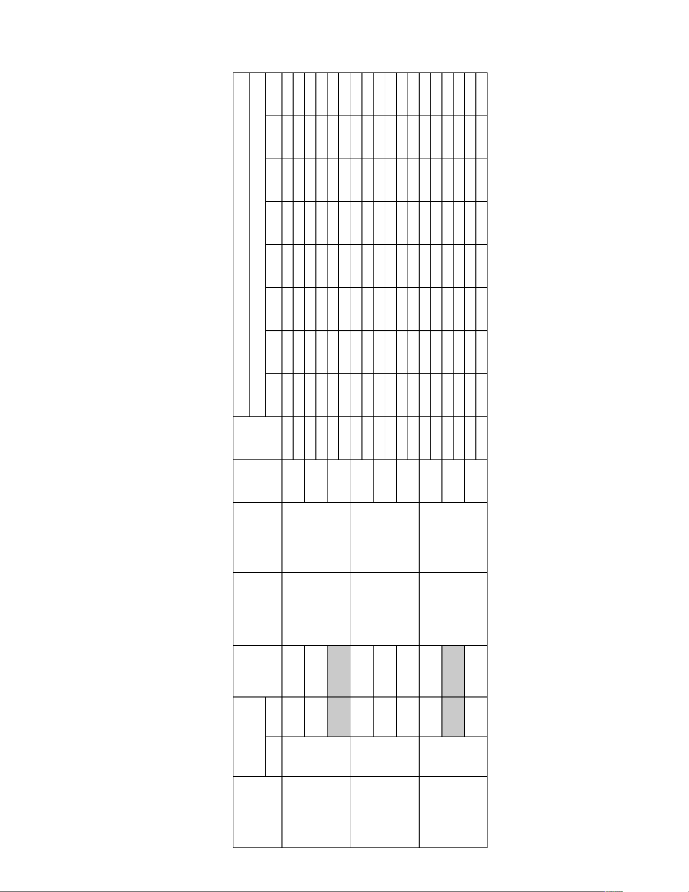
53
INDOOR AIRFLOW PERFORMANCE FOR 3-5 TON SELF-CONTAINED AIR CONDITIONERS
DIRECT DRIVE
!""# $%&' ()*+,)(-. ()-+,)(/. ()0+,)(1. ()2+,)*(. ()/+,)*-. ()3+,)*/. ()1+,)*1. ()4+,)-(.
!"# $%&' $%&$ $%() $(*+ $($( $$,+ )') *%*
-.//0 ,)' ,*1 ,,+ ,(% &*% &'% &1$ %+$
!"# $&)' $&)& $&+& $&&( $%)$ $%(% $$%) )%(
-.//0 ')+ '+) ',% '(( ,)$ ,,1 &*' &%$
!"# $*'* $*%& $+*' $+$) $'%' $,($ $%&, $1%+
-.//0 *+1 *%) +)) +,& +$% ',+ ,)$ ,1%
!"# $%,, $%,( $%&1 $%$* $(+, $(11 $1)& )$(
-.//0 ,)* ,*1 ,'( ,&$ ,$( &+% &%( %*,
!"# $,1& $&)1 $&+& $&&1 $%)' $%(& $($, $1*+
-.//0 '++ ',' '%, '1' ,+' ,%' &** &&(
!"# $*+, $*&' $+)* $+&1 $'+) $'1( $&'& $('*
-.//0 *+& *&( *1, +', +() '** '() ,,)
!"# $'+* $'&$ $,)) $,,+ $,($ $&+$ $&%1 $%*&
-.//0 %,& %'& %*' &1) &%1 &,' &+1 &)$
!"# $*&( $*(1 $+*$ $+&$ $+1% $',) $'$% $,%'
-.//0 &,, &+) &*) ,$' ,() ,,$ ,+& ,+$
!"# (&+' (&$+ (%%' ((() ($(1 $)', $*$' $'(,
-.//0 $1$1 )*) )++ )$* *'( +*$ +1+ '(1
234
#56
789:
$%,;111<
=%)>,'?
789:
ϭϬdžϭϬ
ϭ,Wϳϰϱ
^ƉĞĞĚDŽƚŽƌ
I2AJGK1'1
#56
234
$(1;111<
=%,>$+?
$+,1L((,1
789:
I2AJGK1&*
#56
234
*1;111<
=(%>&,?
$&11L$*11
234
#56
$(1;111<
=%,>$+?
#56
789:
$%,;111<
=%)>,'?
789:
ϭϬdžϭϬ
ϭϮ,Wϯϳϯ
^ƉĞĞĚDŽƚŽƌ
5#"6%7+89:%;+
<"'"7+++++++++++++++++
$=+,6.+++++++++++++++++++
>+"?+8@%%AB
<"'"7+
8@%%A
#56
$(1;111<
=%,>$+?
#56
CDEF!GHCEDIF+-0(;23(+IJKG+LDEMKJN+=FEMJE<LO!F
,+++++.+C%B9PQ&'%B+<%'79R+!"QS%7B9"QB
!M<+,K;B.+L97+C%#9S%7T;E=<;N&''BH-0(;23(+I"#'B
FQ'%7Q&#+8'&'9R+=7%BBU7%HHDQRV%B+N)!)+,W=&.
I2AJGK1%'
234
234
*1;111<
=(%>&,?
$1,1L$%,1
ϭϬdžϭϬ
ϭϮ,Wϯϳϯ
^ƉĞĞĚDŽƚŽƌ
234
XQ9'+<"A%#
<"'"7+8@%%A+M7"Y+
M&R'"7T
$%&'9QP+
DQ@U'++++
5GX;V7++++
,WN.
DĂŶƵĨĂĐƚƵƌĞƌ
ZĞĐŽŵŵĞŶĚĞĚ
;DŝŶDĂdžͿ&D
ŝƌͲ&ůŽǁZĂŶŐĞ
;W^DŽƚŽƌͿ
;W^DŽƚŽƌͿ
;yͲϭϯDŽƚŽƌͿ
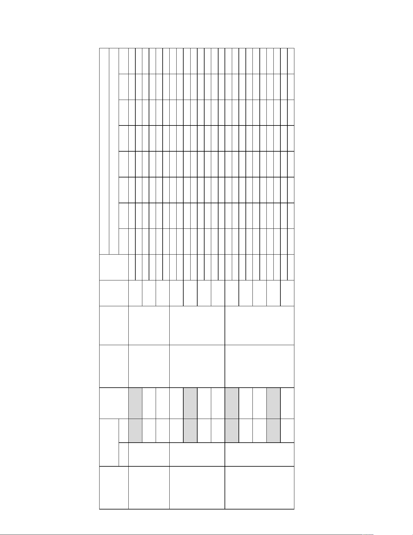
54
INDOOR AIRFLOW PERFORMANCE FOR 3-5 TON SELF-CONTAINED AIR CONDITIONERS
DIRECT DRIVE
!""# $%&' ()*+,)(-. ()-+,)(/. ()0+,)(1. ()2+,)*(. ()/+,)*-. ()3+,)*/. ()1+,)*1. ()4+,)-(.
!"# $%&' $%() $)*( $))( $$+, $$)) $(+* -+-
./001 )$' )%( )&' )*( )+& ),& %(% %)(
!"# $&%, $%-, $%*( $%)) $),& $)&' $)(( $$%+
./001 )*$ )+* )-$ %(* %)( %%& %&, %*)
!"# $*$& $'+* $'%, $'(& $&*% $&)' $%,, $%&-
./001 %*( %,) %-, &$$ &)+ &&$ &'& &**
!"# $&(% $%&' $%$( $)*- $)$) $$*& $(,% $(),
./001 )%) )&& )'' )*+ ),% )-+ %$' %)&
!"# $*++ $*%- $'-+ $''- $')) $&,+ $&%) $%-(
./001 %'& %*+ %,) %-* &$) &)' &&) &'-
!"# $*++ $*%- $'-+ $''- $')) $&,+ $&%) $%-(
./001 %'& %*+ %,) %-* &$) &)' &&) &'-
!"# $+-' $+', $+$, $*,, $*&' $*(+ $'+$ $'%'
./001 &)- &&' &'- &+% &-% '(, ')' '&$
!"# $&(& $%*- $%)* $)*' $))$ $$** $$(+ $(&%
./001 )%% )'( )+( ),( %(( %$- %&( %&&
!"# $*+, $*&$ $'-- $''+ $')$ $&+$ $&%( $%,&
./001 %'& %*& %,* &(- &%( &'* &+( &-$
!"# $,&) $,)( $+,$ $+&$ $+(% $*'- $*$% $'%*
./001 &'' &+- &,- '$* ')- ''$ '+& '+$
!"# $,&) $,)( $+,$ $+&$ $+(% $*'- $*$% $'%*
./001 &'' &+- &,- '$* ')- ''$ '+& '+$
!"# )&+* )&$+ )%%* )))- )$)( $-*' $,$* $*)'
./001 $($( -,- -++ -$, ,*) +,$ +(+ *)(
,ŝŐŚ
$(;$(666666666666666666666
$62<6=+&'>666666666666
'6?9@@A6#B0BC6
7DE$%6#B0BC:
FGHIEJ(*(
GBK6!BBL6
78/96$:66666666666666
23456!BBL6
78/96%:
$106?0/4@6!BBL6
$%'(M$&((6666666666
)NA6?0/4@6!BBL6
$+'(M))'(
GBK66666
78/96):
$((O(((6
=)-P%$>
23456666
78/96%:
$%'O(((6
=%-P'*>
23456666
78/96&:
$)(O(((6
=%'P$+>
,ŝŐŚ
FGHIEJ(&,
#@A678/96
):
GBK678/96
$:
,(O(((6
=)%P&'>
$&((M$,((
>Žǁ
DĞĚ
;dĂƉϮͿ
23456666
78/96&:
$%'O(((6
=%-P'*>
,ŝŐŚ
$(;$(66666666666666666
%M&62<6=''->66666666
&6?9@@A6#B0BC6
7DE$%6#B0BC:
5#"6%7+89:%;+
<"'"7+++++++++++++++++
$=+,6.+++++++++++++++++++
>+"?+8@%%AB
<"'"7+
8@%%A
#@AP6666
78/96%:
,(O(((6
=)%P&'>
DĞĚ
;dĂƉϯͿ
CDEF!GHCEDIF+-(4;-0(;23(+IJKG+LDEMKJN+=FEMJE<LO!F
,+++++.+C%B9PQ&'%B+<%'79R+!"QS%7B9"QB
!M<+,K;B.+L97+C%#9S%7T;E=<;N&''BH-0(;23(+I"#'B
FQ'%7Q&#+8'&'9R+=7%BBU7%HHDQRV%B+N)!)+,W=&.
FGHIEJ(%*
GBK678/96
):
$('(M$%'(
$(;$(66666666666666666
$M)62<6=%+%>66666666
%6?9@@A6#B0BC6
7DE$%6#B0BC:
>Žǁ
XQ9'+<"A%#
<"'"7+8@%%A+M7"Y+
M&R'"7T
$%&'9QP+
DQ@U'++++
5GX;V7++++
,WN.
DĂŶƵĨĂĐƚƵƌĞƌ
ZĞĐŽŵŵĞŶĚĞĚ
;DŝŶDĂdžͿ&D
#@AP6666
78/96%:
$((O(((6
=)-P%$>
DĞĚ
;dĂƉϯͿ
DĞĚ
;dĂƉϰͿ
DĞĚ
;dĂƉϯͿ
>ŽǁŽŽů
;dĂƉϭͿ
>Žǁ
ŝƌͲ&ůŽǁZĂŶŐĞ
;dĂƉϮͿ
78/96&:
78/96$:
78/96&:
78/96):
78/96':
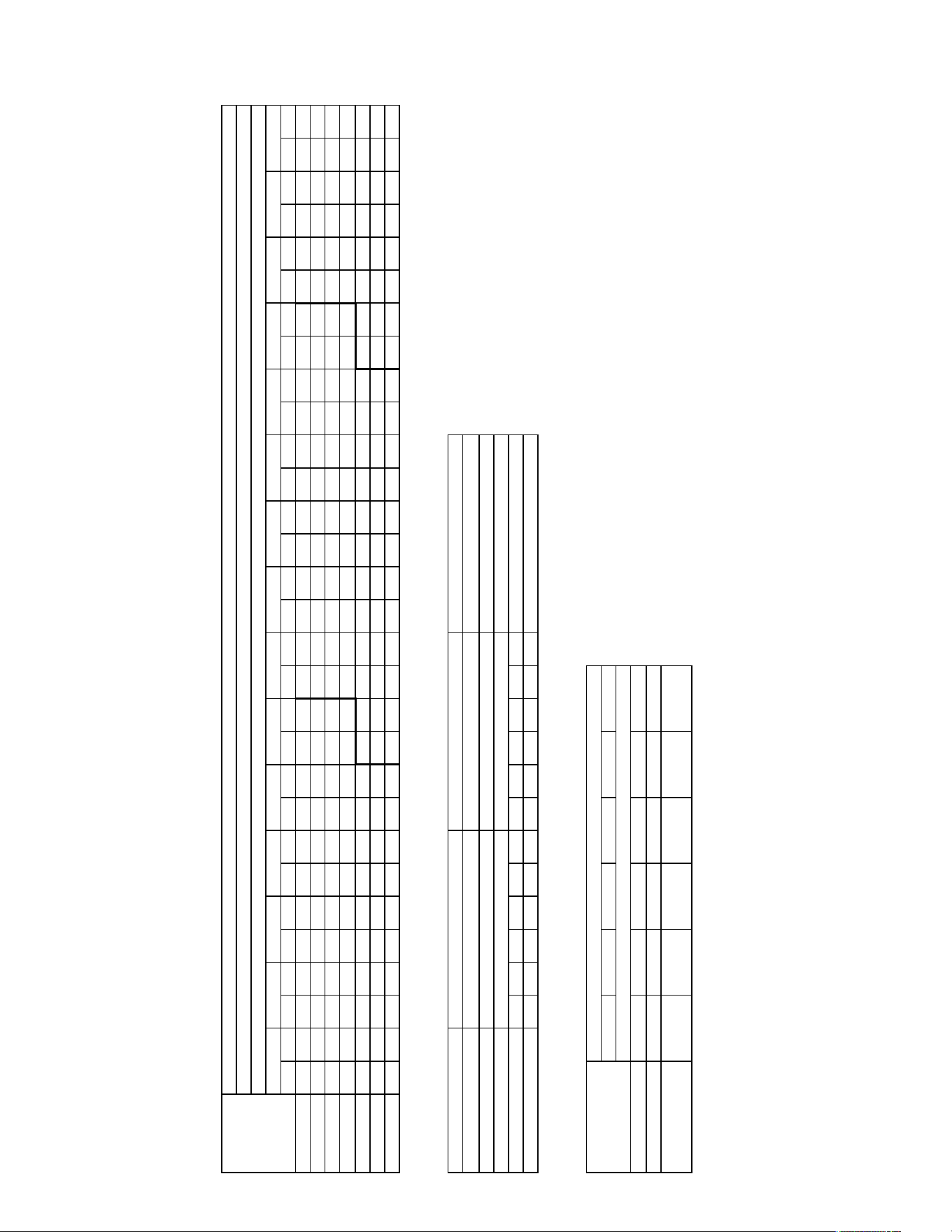
55
INDOOR AIRFLOW PERFORMANCE FOR 3-5 TON SELF-CONTAINED AIR CONDITIONERS
BELT DRIVE
!"# $ !"# $ !"# $ !"# $ !"# $ !"# $ !"# $ !"# $ !"# $ !"# $ !"# $ !"# $ !"# $ !"# $ !"# $
!""#$%&'( ) ) ) ) *!! &&+ ,*' &*- .&, &!& ..* +-. !%- ++. !!+ +'& -"%& +*" -"., +*& --&! +'. --*. +%. -&"+ ++& -&+' +-" -&*% &.&
-"""#$%,&( ) ) **& &&. ,-, &'. ,.- &!+ .%& +&+ .!! +%* !'& +*% -""& +,* -"%! +.- -"!+ +.- --++ +,% --," +*& -&"+ +%% -&++ +&" -&*" &.!
--""#$'-!( ) ) **, &,' ,+, &!' ,!. +&. .', +'' !-& +,, !*% +!& -"-& %"- -"', %"% -"!! %"& --+, +!+ --,& +,. -&"% +'. -&+& ++- -&', &!.
-&""#$'**( *%+ &,. *!+ &!. ,'* ++% .-, +*' .,+ +!" !&, %"! !,* %&& -"&+ %&. -"** %&! --"* %&% --%+ %-+ --,* +!* -&"' +,+ -&+& +%% -&'' +"!
-+""#$*-%( **- +-* ,-* +%- ,,, +,* .+' %"% .!" %&* !%& %%+ !!" %'+ -"+' %'. -",* %'* ---% %%! --%! %+' --." %-* -&". +!- -&+& +'! -&'% +&&
-%""#$**-( **! +'& ,+! +., ,!! %-! .'' %%' !". %*' !'. %,! -""% %., -"%, %.! -"., %.' --&+ %,' --'* %*" --.' %+. -&-- %-" -&+% +,, -&'+ ++,
-'""#$,".( ,"& +!! ,*+ %+% .&- %*% .,* %., !&, '"' !,' '-, -"-! '&+ -"*" '&& -"!. '-* --+& '"% --*+ %.* --!- %*& -&-' %+& -&+* +!* -&'% +'%
" - % + % ' " - & & % '
!-" .*! '(' ,,' ,&. *.& --,* --%' --". ()*) !!* !*.
+,-./0
12!34,$5".!3,!#1+6.7&5-,+58()9::5;<=5->!..5">1/.5?.4-5@!2A.
1BC5555555553DE<555555
63#584FG=
6HIHJBKL5555&5-EM58()9::5N$=5
AEDKHOP555%)'F%&)FQ*)F:R:S5&7"THGP
.UKPCMHD5/KHKBJ5"CPGGVCP5752MJTPG5EW5$HKPC58N"H=
)9(589)%=
)9%589):=
)9&589)R=
)9Q589()=
)9:589(%=
(9%589&)=
(9&589&%=
(9Q589&:=
(9:589&R=
/0123#4567583
9
:
;#/0123#<=13>?#@ABB>13?C
)9*589(:=
)9R589(R=
)9'589%)=
)9X589%%=
(9)589%:=
+,-.0547@!2A.54.3-5,35?,4@542+.S5#7@!2A.5!2Y>-5,35?,4@542+.
(9(589%R=
:DED0#FG4G#$H(
-I&#$+,+(
-I&#$+,+(
-I&#$+,+(
J>DK30#@L3523
*G!M#41E6L#/15N3E30
*G%M#41E6L#/15N3E30
'G,M#41E6L#/15N3E30
:DED0#@L3523
&G%M#O#+G%M#41E6L#/15N3E30
+G%M#O#%G%M#41E6L#/15N3E30
+G%M#O#%G%M#41E6L#/15N3E30
PA0QR#SB3Q
T4:#T5Q83#O#-"+"O-++"
T4:
6,#",+.+-512!5!./2/-1+6.
6EZIEMPMK
/KHM[HC[52M[EEC51BCWDE<577563#584FG=
()))58QR%=
(%))58:**=
(Q))58**(=
(*))58R::=
('))58':)=
%)))58XQQ=
!PGBGKHMJP57752MJTPG5$HKPC58N"H=
H3E#UD1>
"G"+'
"G"%"
"G"*"
"G","
"G".'
"G-""
855=5@PGBOMHKPG5#PKCBJ56EM\PCGBEMG
"G".*
TG@GVG#W6DQDN1X30###TGYG#
/5NB30
"G"'
"G"*
"G",
"G".
"G"!
"G-"
/DKQZ>DK
"G"''
"G"*"
"G"**
"G",&
'G#Y??#6DNBDQ3QE#03R1RE5Q63#ED#?A6E#RE5E16#ED#?3E30N1Q3#WG@G4#5R#RLDKQ#DQ#6L50ERG
"G"."
-G#430ZD0N5Q63#RLDKQ#K1EL#?0[#6D1>#\#RE5Q?50?#&M#$'"G.#NN(#Z1>E30RG
&G#@E5Q?50?#U=:#]#G",'#1^RGI6AGZEG
+G#:DED0#3ZZ1613Q6[#_#."`
%G#JF4#_#H5EER#a#:DED0#WZZ1613Q6[I,%*G
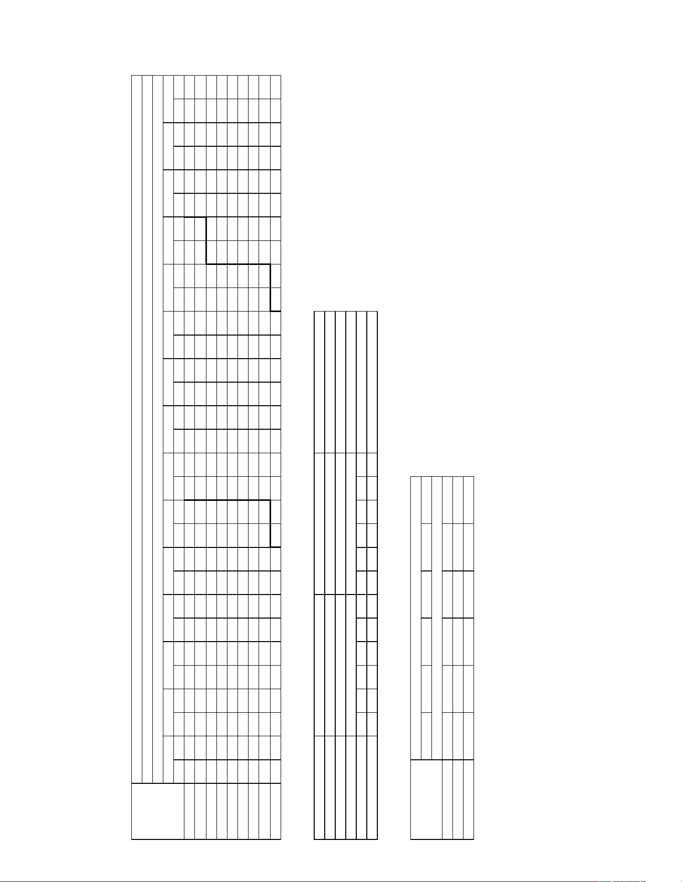
56
INDOOR AIRFLOW PERFORMANCE FOR 3-5 TON SELF-CONTAINED AIR CONDITIONERS
BELT DRIVE
!"# $ !"# $ !"# $ !"# $ !"# $ !"# $ !"# $ !"# $ !"# $ !"# $ !"# $ !"# $ !"# $ !"# $ !"# $
!"##$%&''( ) ) ) ) ) ) *!+ ,"& *+- ,,# -,# ,&' --- ,+& !#&+ ,-' !!!. &!- !!'* &,& !""! &+" !"+" '#" !."" '., !.+! ''- !,"# +#,
!.##$%'!,( ) ) ) ) ) ) *.* ,.+ *-- ,&+ -&* ,+- !#!& &#. !#+! &"- !!"' &&* !!+* &*- !".# '"" !"+- '&+ !."+ '-& !.+, +., !,"! ++.
!,##$%''!( ) ) ) ) *#' ,!* *'! ,&+ -!- ,*" -+' &!# !#." &.- !#*' &+! !!.* '#& !!*- ',! !".- '*# !"*' +"# !... +'. !.++ *#* !,"! *&.
!&##$%+#*( ) ) ) ) *"& ,&* **. ,*' -,# &!+ --& &,- !#,* &*, !!#! '"" !!&! ''! !"## +#. !",* +,' !"-, +-" !..* *,! !.*" *-# !,"' -.-
!'##$%+&&( ) ) +-* ,,- *,- ,-# -#& &". -'# &&- !#!. &-* !#'& '.* !!!& '*! !!', +"& !"!! ++" !"&+ *"! !.#! *+. !.,. -"' !.*& -+- !,"+ !#."
!+##$%*#"( ) ) *!+ ,-. *+. &.# -"* &'- -*! '!! !#." '&, !#*" +## !!.# +,* !!++ +-* !""" *&! !"'' -#& !.#* -'" !.,- !#"! !.-# !#*# !,.! !!.-
!*##$%*&#( +-! ,-# *,, &.+ *-* &+- -&# '", !##" '+# !#&! +!- !#-- ++! !!,' *", !!-# **# !"., -.+ !"+' --+ !.!' !#&- !.&& !!", !.-, !!*- ) )
!-##$%*-+( *!' &,. *+# &*- -". '.+ -+. '*+ !#". +.- !#+# +-. !!!' *&# !!'! -#* !"#, -'- !",& !#.. !"*& !#-* !.", !!'' !.'! !".& !.-* !.#, ) )
"###$%-,,( *,& &-- *-+ '&# -,+ +#. --' +&* !#,, *!' !#*- *+& !!., -.+ !!+' !##" !"!+ !#'* !"&+ !!.+ !"-& !"#+ !.." !"*# !.'+ !.&& ) ) ) )
# ! % . , & # ! " & , &
!#"- -*, '() -!& *&& *!' !"*! !"#+ !!+, **+* !!!! !#+!
,-./01
&/$011$234536768$97:;:8<627$83$1=28$:8<8;2$83$178794;67$>/?/@$<:$:A3B6$36$2A<98:/
#/#*#
!/$@79C394<627$:A3B6$B;8A$19D$23;E$F$:8<61<91$"G$%&#/*$44($C;E879:/
"/$?8<61<91$HIJ$K$/#+&$;L:/M2=/C8/
./$J3839$7CC;2;762D$N$*#O
,/$PQ@$N$R<88:$S$J3839$>CC;2;762DM+,'/
#/#*&
#/!##
2334356789:;<673#6<=8>3?@:A6=78@:7
#/#*'
T/?/U/$>23634;V79$$$T/0/$
#/#&
#/#'
#/#+
#/#*
#/#-
#/!#
W3B6CE3B
#/#&&
#/#'#
#/#''
#/#+"
R78$H3;E
#/#.&
#/#,#
#/#'#
#/#+#
T@J
?-#"-,/,.3BC!3!/0C0.B,?/
?@DE@:6:<
0<;:F;=F3C:F@@=3B8=GH@I3JJ3?K#32LM74
*)))32+N%4
*%))32(OO4
*+))32OO*4
*O))32N((4
*P))32P()4
%)))32'++4
!6787<;:>63JJ3C:>Q673$;<6=32R";4
J3839$?A7<X7
"/*G$Y$./*G$@;82A$W;<47879
./,G$Y$,/,G$@;82A$W;<47879
,/#G$Y$&/#G$@;82A$W;<47879
Z=96:$[576
T@J$T<6\7$Y$!#*#Y!.&#
J3839$Q/@/$%R(
!M"$%.+.(
.M,$%&&-(
.M,$%&&-(
PE3B79$?A7<X7
'/-G$@;82A$W;<47879
'/,G$@;82A$W;<47879
'/,G$@;82A$W;<47879
W9;X7$@<2]<\7
^
J
_$W9;X7$`I;7E1$?=55E;71a
)SO32S*(4
)SN32S*N4
)SP32S%)4
)S'32S%%4
*S)32S%(4
,-./13LJ5!CT/3L/K.3-K3U-L53LC,/V3#J5!CT/3!CWX.3-K3U-L53LC,/
*S*32S%N4
BC!KL-$3"/!K-!#B,?/J+3.-,32*+S)N3YI43.X!//3"XB0/3U/L.35!CT/
B8=333333333KH@I333333
?K#32LM74
?;E;>8<Z3333+3.@:32*+S)N3R$43
T@H<;96333%)PM%&)M+O)M(N(V3&J"Q;76
/[<6=:;H30<;<8>3"=677\=63J3C:>Q673@G3$;<6=32R";4
)S*32S)%4
)S%32S)(4
)S&32S)N4
)S+32S*)4
)S(32S*%4
*S%32S&)4
*S&32S&%4
*S+32S&(4
*S(32S&N4
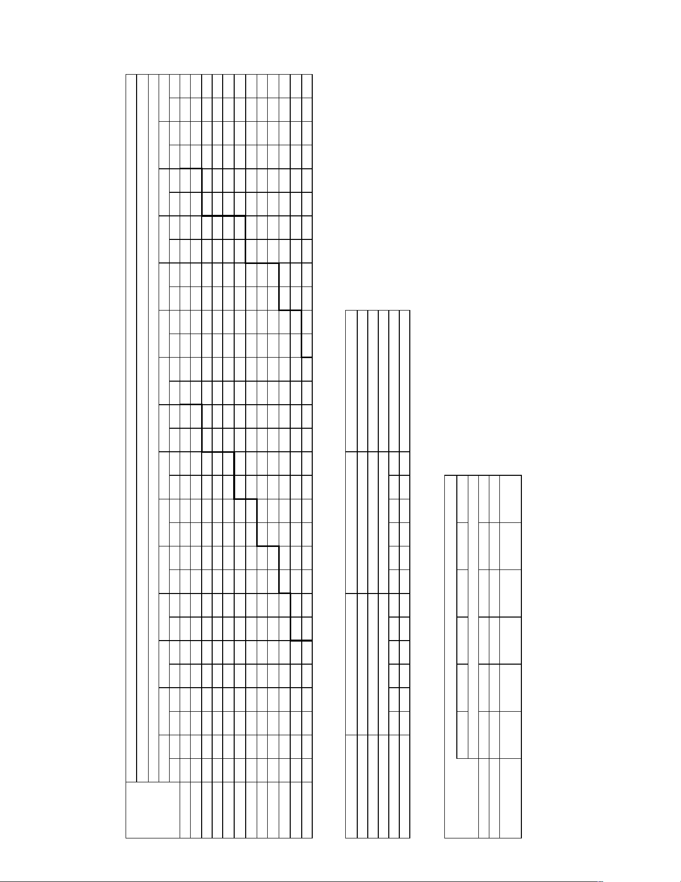
57
INDOOR AIRFLOW PERFORMANCE FOR 3-5 TON SELF-CONTAINED AIR CONDITIONERS
BELT DRIVE
!"# $ !"# $ !"# $ !"# $ !"# $ !"# $ !"# $ !"# $ !"# $ !"# $ !"# $ !"# $ !"# $ !"# $ !"# $
!"##$%&&!' ( ( ( ( )*+ "#+ ,", "-. *!# "&& *)# +!! !#-* ++) !#,& &#& !!"- &++ !!*& )#& !-"* )+, !.## ,!- !.+# ,&, !.*, *-+ !"., *&+
!+##$%)#,' ( ( ( ( ,#* "!. ,)! "+, *.! +#" *,* ++- !#"& &#- !!## &+" !!++ )#+ !-#, )+* !-+* ,!+ !.#, ,)- !.+& *.# !"+) !!-+ !++, !.-#
!&##$%)++' ( ( )*& ".# ,.+ "+" ,*" +#- *+- ++! !##* &#- !#&" &++ !!!, )#* !!)# )&" !--# ,-! !-)# ,,# !.!) *"# !.&. !##! !"+! !-!- !+.* !"-.
!)##$%,#-' ( ( ,!! ")# ,&! +#" *!* +++ *)+ &#) !#.# &&! !#)* )#, !!.+ )). !!,+ ,.- !-." ,*- !-,! *+. !.-) !#!) !.)! !#,! !""- !.#) !+!. !+..
!,##$%,+#' )*- ",+ ,.! +!# ,,, +&. *"" &!& *** &)- !#+! )-* !#*" )&# !!+. ,") !-#! *#, !-", *)! !-*. !#.& !..) !!#- !.,# !!)# !""# !"!# !+## !&+#
!*##$%,*)' ,#" +-! ,&! +)+ *!& &.# *)# &,& !#-. )"+ !#)" ,#+ !!-. ,&& !!)! *-* !-!, **" !-&. !#&# !.#) !!-) !."* !!*& !.,* !-&) !"". !+." !"*) !,#!
-###$%*""' ,.& +*! ,*! &") *"+ )#& **) )&+ !#", ,-) !#*, ,*" !!"+ *+" !!*! !#-# !-.& !#,) !-)* !!+& !.-# !--) !.&! !-** !.** !.). !".) !"") ( (
-!##$%**!' ,)# &&* *-. )-* *)+ )*# !#-+ ,+. !#)" *!) !!-! *,. !!&) !#+# !-!! !!!* !-+" !!*# !-*+ !-&- !..+ !..& !.)" !"!! !"!# !",& !""& !+&! ( (
--##$%!#.,' *#" )+& *++ ,!* !##+ ,,. !#+" *"* !!#! !#-! !!"& !#,+ !!*# !!+& !-.- !--, !-). !.#! !.!. !.)& !.+! !"+. !.,) !+.! !"-- !&#* ( ( ( (
-.##$%!#,+' *.* ,+- *,, *!, !#.& *,+ !#," !#+, !!-, !!-" !!)- !!*& !-!" !-)# !-+" !."+ !-*" !"-! !..! !"** !.&) !+)* !"#- !&!+ !"." !&." ( ( ( (
-"##$%!!..' *)+ *+) !#-- !#-+ !#&, !#*& !!!. !!&) !!+& !-"! !!*, !.!& !-., !.*- !-)) !")# !.!+ !++# !.+# !&.! !.,+ !)!. !"-# !)", ( ( ( ( ( (
-+##$%!!)*' !#!! !#)# !#+) !!"- !#*& !!-& !!"" !-*# !!,& !.&& !--& !""" !-&" !+-. !.#! !&#" !..& !&,) !.)# !))! ( ( ( ( ( ( ( ( ( (
# ! % . " + # ! - & " +
!#-+ **- '() *#* ,&) ,!# !.+. !.#+ !-+, *%%& !!&) !!.#
+,-./0
1,#",+.+-234!2!./4/-3+1.
15675898:
/:;8<;=<248<55=23>=?@5A2BB21C#2DEFGH
*IJJ2DK))H
*LJJ2DL)JH
%JJJ2D'((H
%%JJ2D*J&LH
%(JJ2D**&&H
%IJJ2D*%%KH
!9G>G:;8M92BB248MN9G2$;:9=2DO";H
+/$011$234536768$97:;:8<627$83$1=28$:8<8;2$83$178794;67$>/?/@$<:$:A3B6$36$2A<98:/
#/!##
!/$@79C394<627$:A3B6$B;8A$19D$23;E$F$:8<61<91$-G$%+#/,$44'$C;E879:/
-/$?8<61<91$HIJ$K$/#)+$;L:/M2=/C8/
./$J3839$7CC;2;762D$N$,#O
"/$PQ@$N$R<88:$S$J3839$>CC;2;762DM)"&/
#/!-#
#/!-+
D22H2P9G>Q8;:9G2#9:=>M2158R9=G>58G
#/!#)
Z^/ĐŽŶŽŵŝnjĞƌ
#/#,
#/#*
#/!#
#/!!
#/!-
#/!.
W3B6CE3B
#/#)-
#/#,#
#/#,&
#/#*.
R78$H3;E
#/#)#
#/#,+
#/!##
#/!!#
T@J
J3839$?A7<X7
-/,G$Y$./,G$@;82A$W;<47879
"/#G$Y$+/#G$@;82A$W;<47879
"/#G$Y$+/#G$@;82A$W;<47879
Z=96:$[576
T@J$T<6\7$Y$!-!#Y!+!#
J3839$Q/@/$%R'
.M"$%++*'
!$%)"&'
!$%)"&'
PE3B79$?A7<X7
&/*G$@;82A$W;<47879
&/*G$@;82A$W;<47879
+/)G$@;82A$W;<47879
W9;X7$@<2]<\7
^
J
_$W9;X7$`I;7E1$?=55E;71a
JSI2DS*)H
JSK2DS*KH
JSL2DS%JH
JS'2DS%%H
*SJ2DS%)H
+,-.02EBP!4T.2E.C-2,C2U,EP2E4+.V2#BP!4T.2!4WX-2,C2U,EP2E4+.
*S*2DS%KH
34!CE,$2".!C,!#3+1.B)2-,+2D*KSI2YAH2-X!..2"X3/.2U.E-2P!4T.
ŝƌ
&D>Ɛ
1;7;M>:Z2222)2-582D*KSI2O$H2B2*&2/..!
T5@:;Q9222%JLF%&JF(IJF)K)V2&B"N;G9
.[:9=8;@2/:;:>M2"=9GG\=92B248MN9G25?2$;:9=2DO";H
JS*2DSJ%H
JS%2DSJ)H
JS&2DSJKH
JS(2DS*JH
JS)2DS*%H
*S%2DS&JH
*S&2DS&%H
*S(2DS&)H
*S)2DS&KH
78/96):
&ůŽǁ
ZĂŵƉĞƌ
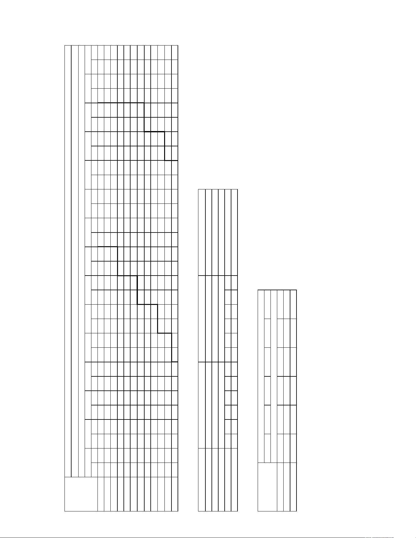
58
INDOOR AIRFLOW PERFORMANCE FOR 3-5 TON SELF-CONTAINED AIR CONDITIONERS
BELT DRIVE
!"# $ !"# $ !"# $ !"# $ !"# $ !"# $ !"# $ !"# $ !"# $ !"# $ !"# $ !"# $ !"# $ !"# $ !"# $
!"##$%&&!' ( ( ( ( ( ( )*" "&& *+, "-) **& ,++ -+, ,)" -*+ &.! !#+# &)" !#)) )+. !!.. )-, !!&& *&" !.#- -+- !.,! !#!- !.-. !!#"
!,##$%)#*' ( ( ( ( ( ( *## "*" *,# ,!- *-- ,,* -") &#" --" &,, !#"# )!! !#*, ))+ !!.- *"! !!). -!" !.!" --. !.,, !#)& !.-, !!&&
!&##$%),,' ( ( ( ( )&& ")* *!& ,!! *&, ,"- -!+ ,-+ -&# &"+ !##& &-* !#,! ),* !#-, *." !!+) *-, !!)- -). !..# !#,, !.&# !!"+ !+## !.+!
!)##$%*#.' ( ( ( ( )*, ,#- *++ ,"& **! ,*- -.* &+) -)" &-# !#!* )"- !#&. *!+ !!#, **+ !!"& -,- !!*) !#"# !..) !!.& !.&, !.!* !+#+ !+!#
!*##$%*,#' ( ( ),, ,#, *#" ,,# *,! ,-! *-* &+) -"+ &*- -** )") !#+! *!# !#)" *)* !!!, -,. !!,& !#+! !!-, !!!& !.+" !.#) !.)! !+#. !+#* !+-)
!-##$%*-)' )!& "-! ))& ,&# *.+ &## *&- &", -!, &-, -,- ),! !##+ *!. !#", *)- !#*& -,! !!.) !#.- !!&& !!!+ !.#" !.#. !.". !.-& !.)* !+-& !+!" !"-&
.###$%-""' )", ,&. )-) &!, *"+ &,* **- )#) -++ )&. -)& *.! !#!* **) !#,- -,* !#-- !#+" !!+- !!!& !!)) !.#+ !.!" !.-& !.,# !+-" !.*, !"-* !+.# !&#.
.!##$%--!' ))+ &+) *!- &)- *&" ).& -#* ))- -,! *+) --+ -#! !#+" -)# !#)" !#", !!!+ !!., !!,! !.!! !!** !+#+ !.." !+-- !.,- !,#. !.-+ !&#- ( (
..##$%!#+*' )-) )#& *". ),! **& *#+ -.- *&# -)! -.. !#!! --# !#,! !#&+ !#-# !!". !!.* !..& !!&, !+!& !.## !"!! !.+, !,!. !.&- !&!* ( ( ( (
.+##$%!#*,' *.. )*+ *&, *++ -#* *** -,# -"- --# !#!, !#+# !#*) !#&- !!&" !!#& !.") !!"+ !++, !!)- !".- !.!+ !,.* !.") !&++ !.)- !)"+ ( ( ( (
."##$%!!++' *") *)# **- -." -+! -*+ -)! !#"* !#!! !!!* !#"- !!-" !#*) !.), !!.+ !+&. !!,- !"," !!-+ !,,! !..) !&,, !.,- !)&+ !.-! !*)* ( ( ( (
.,##$%!!)-' *)+ -&& -!" !#.+ -," !#*) --" !!,, !#+. !..- !#&- !+#- !!#& !+-" !!"! !"*, !!), !,*! !.#- !&*+ !."! !)-# !.). !-#+ ( ( ( ( ( (
# ! % + " , # ! . & " ,
-&) -+& '(( *,, *!& )&- !."* !.#+ !!&+ ))%& !#)* !#".
*+,-./
"/$012$3$45667$8$9:6:;$<==>?>@A?BC)"&/
,/$DEE$?:FG:A@A6$;@7>765A?@$6:$EH?6$7656>?$6:$E@6@;F>A@$</I/2$57$7J:KA$:A$?J5;67/
011213456789:451#4:;6<1=>8?4;56>85
#/!.
#/!+
!/$2@;=:;F5A?@$7J:KA$K>6J$E;B$?:>L$M$765AE5;E$.N$%,#/*$FF'$=>L6@;7/
./$I65AE5;E$OP9$Q$/#),$>R7/C?H/=6/
+/$9:6:;$@==>?>@A?B$3$*#S
T/I/U/$<?:A:F>V@;$$$T/D/$
#/#*
#/#-
#/!#
#/!!
#/!.#
#/!.,
W:KA=L:K
#/#).
#/#*#
#/#*&
#/#-+
#/!##
#/!#)
4@6$O:>L
#/#)#
#/#*,
#/!##
#/!!#
=+#"+*-*,1@A!1!-.A.,@*=-
=>BC>848:
.:98D9;D1A8D>>;1@6;EF>G1HH1=I#10JK52
)L((10MNN2
)O((10ON(2
%(((10'PP2
%%((10)(&O2
%P((10))&&2
%L((10)%%M2
!4565:98<41HH1A8<Q451$9:4;10R"92
@A!IJ+$1"-!I+!#@*=-HN1,+*10)MSL1TG21,U!--1"[email protected],13!AW-
@6;111111111IF>G111111
=I#10JK52
=9C9<6:X1111N1,>810)MSL1R$21)P1.--!
W>F:974111%(OK%&(KPL(KNMNY1&H"Q954
-Z:4;89F1.:9:6<1";455[;41H1A8<Q451>E1$9:4;10R"92
(S)10S(%2
(S%10S(N2
(S&10S(M2
(SP10S)(2
(SN10S)%2
)S%10S&(2
)S&10S&%2
)SP10S&N2
)SN10S&M2
W;>X@$25?Y5Z@
[
9
\$W;>X@$]P>@LE$IHGGL>@E^
(SL10S)N2
(SM10S)M2
(SO10S%(2
(S'10S%%2
)S(10S%N2
*+,-/1JH3!AW-1J-I,1+I1V+J31JA*-Y1#H3!AW-1!A\U,1+I1V+J31JA*-
)S)10S%M2
9:6:;$1/2/$%4'
+C"$%,,-'
!$%)"&'
!$%)"&'
0L:K@;$IJ@5X@
&/-N$2>6?J$W>5F@6@;
&/-N$2>6?J$W>5F@6@;
&/"N$2>6?J$W>5F@6@;
T29
9:6:;$IJ@5X@
./*N$_$+/*N$2>6?J$W>5F@6@;
"/#N$_$,/#N$2>6?J$W>5F@6@;
"/#N$_$,/#N$2>6?J$W>5F@6@;
`H;A7$aG@A
T29$T5AZ@$_$!#*#_!+"*
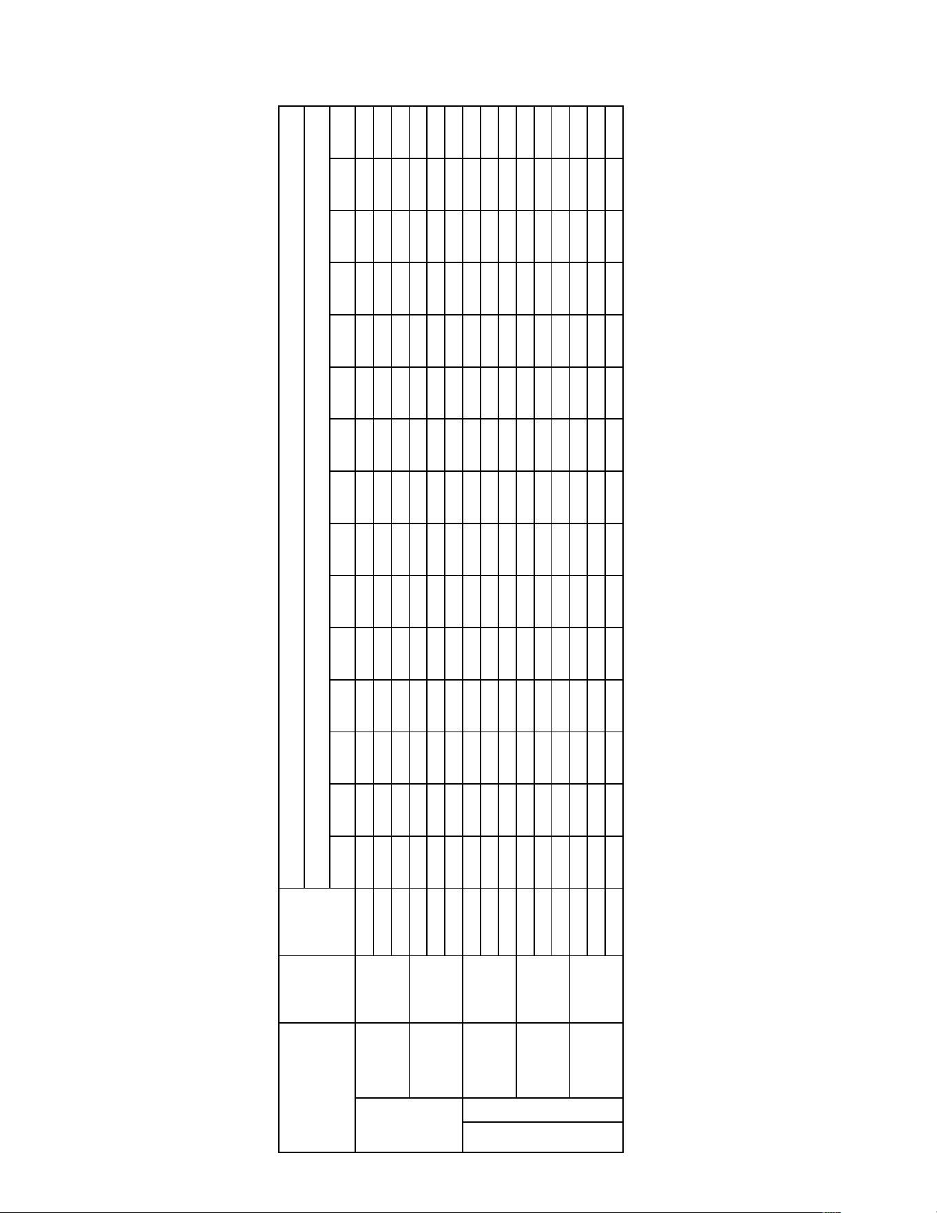
59
INDOOR AIRFLOW PERFORMANCE FOR 3-5 TON SELF-CONTAINED AIR CONDITIONERS
BELT DRIVE
!"#$%"!&' !"&$%"!(' !")$%"!*' !"+$%"#!' !"($%"#&' !",$%"#(' !"*$%"#*' !"-$%"&!' !".$%"&&' #"!$%"&(' #"#$%"&*' #"&$%")!' #")$%")&' #"+$%")(' #"($%")*'
!"#
$%&% $'$( $''% $')% $'*+ $''( $',) $')% $'$, $'+% $%*) $%'$ $-(& $-), $--&
./#
)$+ )(( *,' (++ (*% &'+ &&- $+-) $+(+ $$%+ $$)+ $$() $-$% $-,' $-&-
01223
-$, -)) %$' %,+ '+& ')) ,$, ,,+ ,&& ),% )(% *$+ *'- *&$ (%,
!"#
$,*& $,&& $)-) $)'- $)'* $)'- $),$ $)'( $)'' $)%% $)$) $,*+ $,-% $'&& $%&*
./#
)*) *%' *&% (,+ &+% &,- $++' $+,' $+&, $$%& $$() $--, $-), $-&* $%-$
01223
%+- %'& '+' ',' ,+( ,)+ )$' )*+ *$* **- (%) ((, &'- &(( &(&
!"#
$*,( $*(' $*&) $(+$ $(-+ $(-, $(%' $(-) $(%- $(%+ $($' $($* $*&, $)(- $,)$
./#
*-- *(- (%) (*' &%- &*$ $+-- $+), $$$' $$,+ $$(& $-%$ $-*% $%$& $%'(
01223
%&- ',$ ,+( ,'* )$, ))' *-( *() (,' &+( &)( $+%) $$+) $$'* $$-*
!"#
-+*, -+(* -+(( -+(, -+&+ -$+$ -$$' -$+) -$+, -$+$ -+%' -++$ $&'% $(,, $)-(
./#
*&( ('% (&* &%) &($ $+$( $+,* $+&) $$%) $$*+ $-+% $-'$ $-*- $%+& $%'&
01223
,&+ )') *$' *)& (%, (&+ &,% $+$' $+(- $$%* $$)* $$&% $--+ $-'$ $$()
!"#
---- ---+ --%& --'' --)$ --%) --$) -$(+ -$') -$$+ -+,$ -+$+ $&,( $()% $)%)
./#
('$ ((% &%% &*$ $++( $+') $+*, $$+) $$'$ $$*% $-+* $-%( $-*% $%$- $%,$
01223
*$* *** (,) &-$ &(' $+%* $+,' $+(% $$$, $$'% $$*) $-+$ $-%% $-,+ $$&,
/01$%234'$567$89:6;97<3=>13?@AA4B&!-3&)!3+,!$CD:A4
EFA97F@:$GA@A6H$>7944I79BBJFHK94$?"/"$%L>@'
#+!!
#,!!
#-!!
MNOEP$=9Q979FH9$RSMJOG$?JOT$E/1$1NON=GR$6F$O@U:9$DQ$/DFA9FA4$QD7$@67Q:DV$@WXI4AY9FA4"
ϱͲdKEϭϱ^Z
"14565781294:
-4;5<21:85!==>94:
$325<21:85!==>94:
"?!@A.B5
<C@@DEF
A/@DAE?G
"?!@A.B5
<C@@DEF
A/@DAE?G
A/@DAE?G
&!!!
&&!!
/01$
G9AA6F\
ϮͲ^d'
sΘsDK>^

60
AUXILIARY HEATER KITS CHARACTERISTICS AND APPLICATION
RHEEM/RUUD
X
YZAABBCCDDEEFF
AIR COND.
HEATER KIT MAX. FUSE
MAX FUSE MAX FUSE OR CKT.
OR CKT. BKR. OR CKT. BKR. BKR. SIZE
UNIT
S
IZE (CKT. HEATER SIZE (CKT. (CKT. BKR.
MODEL
HEATER KIT UNIT MIN. BKR. MUST BE KIT MIN. BKR. MUST BE AIR COND. MUST BE
NUMBER
M
ODEL NO. HEATER KW HEATER CKT. HACR TYPE CKT. HACR TYPE MIN. CKT. HACR TYPE
RLNN-
RXJJ- @ 480 KIT FLA AMPACITY FOR USA) AMPACITY FOR USA) AMPACITY FOR USA)
NONE - - 11 15 - - 11 15
A06D 5.6 6.7 11 15 9 15 11 15
A10D 9.6 11.6 18 20 15 15 11 15
A12D 11.2 13.5 20 20 17 20 11 15
A15D 14.4 17.4 25 25 22 25 11 15
A20D 19.2 23.3 32 35 30 30 11 15
NONE - - 10 15 - - 10 15
A06D 5.6 6.7 11 15 9 15 10 15
A10D 9.6 11.6 17 20 15 15 10 15
A12D 11.2 13.5 19 20 17 20 10 15
A15D 14.4 17.4 24 25 22 25 10 15
A20D 19.2 23.3 31 35 30 30 10 15
NONE - - 10 15 - - 10 15
A06D 5.6 6.7 11 15 9 15 10 15
A10D 9.6 11.6 17 20 15 15 10 15
A12D 11.2 13.5 19 20 17 20 10 15
A15D 14.4 17.4 24 25 22 25 10 15
A20D 19.2 23.3 31 35 30 30 10 15
NONE - - 11 15 - - 11 15
A06D 5.6 6.7 11 30 9 15 11 15
A10D 9.6 11.6 18 30 15 15 11 15
A12D 11.2 13.5 20 30 17 20 11 15
A15D 14.4 17.4 25 30 22 25 11 15
A20D 19.2 23.3 32 35 30 30 11 15
NONE - - 11 15 - - 11 15
A06D 5.6 6.7 11 15 9 15 11 15
A10D 9.6 11.6 17 20 15 15 11 15
A12D 11.2 13.5 19 20 17 20 11 15
A15D 14.4 17.4 24 25 22 25 11 15
A20D 19.2 23.3 31 35 30 30 11 15
NONE - - 11 15 - - 11 15
A06D 5.6 6.7 11 15 9 15 11 15
A10D 9.6 11.6 17 20 15 15 11 15
A12D 11.2 13.5 19 20 17 20 11 15
A15D 14.4 17.4 24 25 22 25 11 15
A20D 19.2 23.3 32 35 30 30 11 15
NONE - - 14 20 - - 14 20
A06D 5.6 6.7 14 20 9 15 14 20
A10D 9.6 11.6 20 20 15 15 14 20
A12D 11.2 13.5 22 25 17 20 14 20
A15D 14.4 17.4 27 30 22 25 14 20
A20D 19.2 23.3 35 35 30 30 14 20
NONE - - 13 20 - - 13 20
A06D 5.6 6.7 13 20 9 15 13 20
A10D 9.6 11.6 17 20 15 15 13 20
A12D 11.2 13.5 19 20 17 20 13 20
A15D 14.4 17.4 24 25 22 25 13 20
A20D 19.2 23.3 32 35 30 30 13 20
A24D 24 28.9 39 40 37 40 13 20
NONE - - 13 20 - - 13 20
A06D 5.6 6.7 13 20 9 15 13 20
A10D 9.6 11.6 18 20 15 15 13 20
A12D 11.2 13.5 20 20 17 20 13 20
A15D 14.4 17.4 25 25 22 25 13 20
A20D 19.2 23.3 32 35 30 30 13 20
A24D 24 28.9 39 40 37 40 13 20
Rheem Air Conditioning Division
Rating Plate Stamping Instructions
Electric Heat Data for Package Units
A036DK
A048DL
A048DK
A036DM
A036DL
A060DM
A060DL
A060DK
A048DM
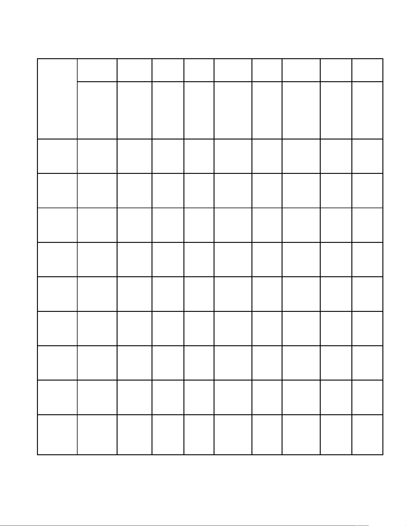
61
AUXILIARY HEATER KITS CHARACTERISTICS AND APPLICATION
RHEEM/RUUD
X
YZAABBCCDDEEFF
AIR COND.
HEATER KIT MAX. FUSE
MAX FUSE MAX FUSE OR CKT.
OR CKT. BKR. OR CKT. BKR. BKR. SIZE
UNIT
S
IZE (CKT. HEATER SIZE (CKT. (CKT. BKR.
MODEL
HEATER KIT UNIT MIN. BKR. MUST BE KIT MIN. BKR. MUST BE AIR COND. MUST BE
NUMBER
M
ODEL NO. HEATER KW HEATER CKT. HACR TYPE CKT. HACR TYPE MIN. CKT. HACR TYPE
RLNN-
RXJJ- @ 208/240 KIT FLA AMPACITY FOR USA) AMPACITY FOR USA) AMPACITY FOR USA)
NONE - - 17/17 25/25 - - 17/17 25/25
A06C 4.2/5.6 11.7/13.5 20/22 25/25 15/17 15/20 17/17 25/25
A10C 7.2/9.6 20/23.1 30/34 30/35 25/29 25/30 17/17 25/25
A12C 8.4/11.2 23.4/27 35/39 35/40 30/34 30/35 17/17 25/25
A15C 10.8/14.4 30.1/34.7 43/49 45/50 38/44 40/45 17/17 25/25
A20C 14.4/19.2 40/46.3 55/63 60/70 50/58 50/60 17/17 25/25
NONE - - 16/16 20/20 - - 16/16 20/20
A06C 4.2/5.6 11.7/13.5 19/21 20/25 15/17 15/20 16/16 20/20
A10C 7.2/9.6 20/23.1 29/33 30/35 25/29 25/30 16/16 20/20
A12C 8.4/11.2 23.4/27 33/38 35/40 30/34 30/35 16/16 20/20
A15C 10.8/14.4 30.1/34.7 42/47 45/50 38/44 40/45 16/16 20/20
A20C 14.4/19.2 40/46.3 54/62 60/70 50/58 50/60 16/16 20/20
NONE - - 22/22 35/35 - - 22/22 35/35
A06C 4.2/5.6 11.7/13.5 22/22 35/35 15/17 15/20 22/22 35/35
A10C 7.2/9.6 20/23.1 30/34 35/35 25/29 25/30 22/22 35/35
A12C 8.4/11.2 23.4/27 35/39 35/40 30/34 30/35 22/22 35/35
A15C 10.8/14.4 30.1/34.7 43/49 45/50 38/44 40/45 22/22 35/35
A20C 14.4/19.2 40/46.3 55/63 60/70 50/58 50/60 22/22 35/35
NONE - - 21/21 30/30 - - 21/21 30/30
A06C 4.2/5.6 11.7/13.5 21/21 30/30 15/17 15/20 21/21 30/30
A10C 7.2/9.6 20/23.1 29/33 30/35 25/29 25/30 21/21 30/30
A12C 8.4/11.2 23.4/27 33/38 35/40 30/34 30/35 21/21 30/30
A15C 10.8/14.4 30.1/34.7 42/47 45/50 38/44 40/45 21/21 30/30
A20C 14.4/19.2 40/46.3 54/62 60/70 50/58 50/60 21/21 30/30
NONE - - 22/22 30/30 - - 22/22 30/30
A06C 4.2/5.6 11.7/13.5 22/22 30/30 15/17 15/20 22/22 30/30
A10C 7.2/9.6 20/23.1 30/34 30/35 25/29 25/30 22/22 30/30
A12C 8.4/11.2 23.4/27 34/39 35/40 30/34 30/35 22/22 30/30
A15C 10.8/14.4 30.1/34.7 42/48 45/50 38/44 40/45 22/22 30/30
A20C 14.4/19.2 40/46.3 55/63 60/70 50/58 50/60 22/22 30/30
NONE - - 27/27 40/40 - - 27/27 40/40
A06C 4.2/5.6 11.7/13.5 27/27 40/40 15/17 15/20 27/27 40/40
A10C 7.2/9.6 20/23.1 32/35 40/40 25/29 25/30 27/27 40/40
A12C 8.4/11.2 23.4/27 36/40 40/40 30/34 30/35 27/27 40/40
A15C 10.8/14.4 30.1/34.7 44/50 45/50 38/44 40/45 27/27 40/40
A20C 14.4/19.2 40/46.3 57/64 60/70 50/58 50/60 27/27 40/40
NONE - - 26/26 40/40 - - 26/26 40/40
A06C 4.2/5.6 11.7/13.5 26/26 40/40 15/17 15/20 26/26 40/40
A10C 7.2/9.6 20/23.1 30/34 40/40 25/29 25/30 26/26 40/40
A12C 8.4/11.2 23.4/27 34/39 40/40 30/34 30/35 26/26 40/40
A15C 10.8/14.4 30.1/34.7 42/48 45/50 38/44 40/45 26/26 40/40
A20C 14.4/19.2 40/46.3 55/63 60/70 50/58 50/60 26/26 40/40
NONE - - 27/27 40/40 - - 27/27 40/40
A06C 4.2/5.6 11.7/13.5 27/27 40/40 15/17 15/20 27/27 40/40
A10C 7.2/9.6 20/23.1 31/35 40/40 25/29 25/30 27/27 40/40
A12C 8.4/11.2 23.4/27 35/39 40/40 30/34 30/35 27/27 40/40
A15C 10.8/14.4 30.1/34.7 43/49 45/50 38/44 40/45 27/27 40/40
A20C 14.4/19.2 40/46.3 56/63 60/70 50/58 50/60 27/27 40/40
A24C 18/24 50/57.7 68/78 70/80 63/73 70/80 27/27 40/40
Rheem Air Conditioning Division
Rating Plate Stamping Instructions
Electric Heat Data for Package Units
A036CK
A048CL
A048CK
A036CM
A036CL
A060CM
A060CL
A060CK
A048CM

62
AUXILIARY HEATER KITS CHARACTERISTICS AND APPLICATION
RHEEM/RUUD
X
YZAABBCCDDEEFF
AIR COND.
HEATER KIT MAX. FUSE
MAX FUSE MAX FUSE OR CKT.
OR CKT. BKR. OR CKT. BKR. BKR. SIZE
UNIT
S
IZE (CKT. HEATER SIZE (CKT. (CKT. BKR.
MODEL
HEATER KIT UNIT MIN. BKR. MUST BE KIT MIN. BKR. MUST BE AIR COND. MUST BE
NUMBER
M
ODEL NO. HEATER KW HEATER CKT. HACR TYPE CKT. HACR TYPE MIN. CKT. HACR TYPE
RLNN-
RXJJ- @ 480 KIT FLA AMPACITY FOR USA) AMPACITY FOR USA) AMPACITY FOR USA)
NONE - - 11 15 - - 11 15
A06D 5.6 6.7 11 15 9 15 11 15
A10D 9.6 11.6 18 20 15 15 11 15
A12D 11.2 13.5 20 20 17 20 11 15
A15D 14.4 17.4 25 25 22 25 11 15
A20D 19.2 23.3 32 35 30 30 11 15
NONE - - 10 15 - - 10 15
A06D 5.6 6.7 11 15 9 15 10 15
A10D 9.6 11.6 17 20 15 15 10 15
A12D 11.2 13.5 19 20 17 20 10 15
A15D 14.4 17.4 24 25 22 25 10 15
A20D 19.2 23.3 31 35 30 30 10 15
NONE - - 10 15 - - 10 15
A06D 5.6 6.7 11 15 9 15 10 15
A10D 9.6 11.6 17 20 15 15 10 15
A12D 11.2 13.5 19 20 17 20 10 15
A15D 14.4 17.4 24 25 22 25 10 15
A20D 19.2 23.3 31 35 30 30 10 15
NONE - - 11 15 - - 11 15
A06D 5.6 6.7 11 30 9 15 11 15
A10D 9.6 11.6 18 30 15 15 11 15
A12D 11.2 13.5 20 30 17 20 11 15
A15D 14.4 17.4 25 30 22 25 11 15
A20D 19.2 23.3 32 35 30 30 11 15
NONE - - 11 15 - - 11 15
A06D 5.6 6.7 11 15 9 15 11 15
A10D 9.6 11.6 17 20 15 15 11 15
A12D 11.2 13.5 19 20 17 20 11 15
A15D 14.4 17.4 24 25 22 25 11 15
A20D 19.2 23.3 31 35 30 30 11 15
NONE - - 11 15 - - 11 15
A06D 5.6 6.7 11 15 9 15 11 15
A10D 9.6 11.6 17 20 15 15 11 15
A12D 11.2 13.5 19 20 17 20 11 15
A15D 14.4 17.4 24 25 22 25 11 15
A20D 19.2 23.3 32 35 30 30 11 15
NONE - - 14 20 - - 14 20
A06D 5.6 6.7 14 20 9 15 14 20
A10D 9.6 11.6 20 20 15 15 14 20
A12D 11.2 13.5 22 25 17 20 14 20
A15D 14.4 17.4 27 30 22 25 14 20
A20D 19.2 23.3 35 35 30 30 14 20
NONE - - 13 20 - - 13 20
A06D 5.6 6.7 13 20 9 15 13 20
A10D 9.6 11.6 17 20 15 15 13 20
A12D 11.2 13.5 19 20 17 20 13 20
A15D 14.4 17.4 24 25 22 25 13 20
A20D 19.2 23.3 32 35 30 30 13 20
A24D 24 28.9 39 40 37 40 13 20
NONE - - 13 20 - - 13 20
A06D 5.6 6.7 13 20 9 15 13 20
A10D 9.6 11.6 18 20 15 15 13 20
A12D 11.2 13.5 20 20 17 20 13 20
A15D 14.4 17.4 25 25 22 25 13 20
A20D 19.2 23.3 32 35 30 30 13 20
A24D 24 28.9 39 40 37 40 13 20
Rheem Air Conditioning Division
Rating Plate Stamping Instructions
Electric Heat Data for Package Units
A036DK
A048DL
A048DK
A036DM
A036DL
A060DM
A060DL
A060DK
A048DM
63
AUXILIARY HEATER KITS CHARACTERISTICS AND APPLICATION–RLNL
RHEEM/RUUD
X
YZAABBCCDDEEFF
AIR COND.
HEATER KIT MAX. FUSE
MAX FUSE MAX FUSE OR CKT.
OR CKT. BKR. OR CKT. BKR. BKR. SIZE
UNIT
S
IZE (CKT. HEATER SIZE (CKT. (CKT. BKR.
MODEL
HEATER KIT UNIT MIN. BKR. MUST BE KIT MIN. BKR. MUST BE AIR COND. MUST BE
NUMBER
M
ODEL NO. HEATER KW HEATER CKT. HACR TYPE CKT. HACR TYPE MIN. CKT. HACR TYPE
RLNN-
RXJJ- @ 208/240 KIT FLA AMPACITY FOR USA) AMPACITY FOR USA) AMPACITY FOR USA)
NONE - - 24/24 35/35 - - 24/24 35/35
A06J 4.2/5.6 20.2/23.3 31/35 35/35 26/30 30/30 24/24 35/35
A10J 7.2/9.6 34.6/40 49/55 50/60 44/50 45/50 24/24 35/35
A12J 8.4/11.2 40.4/46.7 56/64 60/70 51/59 60/60 24/24 35/35
A15J 10.8/14.4 51.9/60 70/80 70/80 65/75 70/80 24/24 35/35
A20J 14.4/19.2 69.3/80 92/105 100/110 87/100 90/100 24/24 35/35
NONE - - 31/31 50/50 - - 31/31 50/50
A06J 4.2/5.6 20.2/23.3 31/35 50/50 26/30 30/30 31/31 50/50
A10J 7.2/9.6 34.6/40 49/55 50/60 44/50 45/50 31/31 50/50
A12J 8.4/11.2 40.4/46.7 56/64 60/70 51/59 60/60 31/31 50/50
A15J 10.8/14.4 51.9/60 70/80 70/80 65/75 70/80 31/31 50/50
A20J 14.4/19.2 69.3/80 92/105 100/110 87/100 90/100 31/31 50/50
NONE - - 40/40 60/60 - - 40/40 60/60
A06J 4.2/5.6 20.2/23.3 40/40 60/60 26/30 30/30 40/40 60/60
A10J 7.2/9.6 34.6/40 50/57 60/60 44/50 45/50 40/40 60/60
A12J 8.4/11.2 40.4/46.7 57/65 60/70 51/59 60/60 40/40 60/60
A15J 10.8/14.4 51.9/60 71/82 80/90 65/75 70/80 40/40 60/60
A20J 14.4/19.2 69.3/80 93/107 100/110 87/100 90/100 40/40 60/60
RHEEM/RUUD
XYZAABBCCDDEEFF
AIR COND.
HEATER KIT MAX. FUSE
MAX FUSE MAX FUSE OR CKT.
OR CKT. BKR. OR CKT. BKR. BKR. SIZE
UNIT
SIZE (CKT. HEATER SIZE (CKT. (CKT. BKR.
MODEL
HEATER KIT UNIT MIN. BKR. MUST BE KIT MIN. BKR. MUST BE AIR COND. MUST BE
NUMBER
MODEL NO. HEATER KW HEATER CKT. HACR TYPE CKT. HACR TYPE MIN. CKT. HACR TYPE
RLNN-
RXJJ- @ 600 KIT FLA AMPACITY FOR USA) AMPACITY FOR USA) AMPACITY FOR USA)
NONE - - 7 15 - - 7 15
A15Y 14.4 13.9 19 20 18 20 7 15
A20Y 19.2 18.8 26 30 24 25 7 15
NONE - - 7 15 - - 7 15
A15Y 14.4 13.9 19 20 18 20 7 15
A20Y 19.2 18.8 26 30 24 25 7 15
NONE - - 8 15 - - 8 15
A15Y 14.4 13.9 19 20 18 20 8 15
A20Y 19.2 18.8 26 30 24 25 8 15
NONE - - 8 15 - - 8 15
A15Y 14.4 13.9 19 20 18 20 8 15
A20Y 19.2 18.8 26 30 24 25 8 15
NONE - - 10 15 - - 10 15
A15Y 14.4 13.9 19 20 18 20 10 15
A20Y 19.2 18.8 26 30 24 25 10 15
NONE - - 10 15 - - 10 15
A15Y 14.4 13.9 20 20 18 20 10 15
A20Y 19.2 18.8 26 30 24 25 10 15
A060JK
A048JK
Rheem Air Conditioning Division
Rating Plate Stamping Instructions
Electric Heat Data for Package Units
A036JK
Rheem Air Conditioning Division
Rating Plate Stamping Instructions
Electric Heat Data for Package Units
A036YL
A060YL
A060YM
A036YM
A048YL
A048YM
64
AUXILIARY HEATER KITS CHARACTERISTICS AND APPLICATION–RLNL
RHEEM/RUUD
X
YZAABBCCDDEEFF
AIR COND.
HEATER KIT MAX. FUSE
MAX FUSE MAX FUSE OR CKT.
OR CKT. BKR. OR CKT. BKR. BKR. SIZE
UNIT
S
IZE (CKT. HEATER SIZE (CKT. (CKT. BKR.
MODEL
HEATER KIT UNIT MIN. BKR. MUST BE KIT MIN. BKR. MUST BE AIR COND. MUST BE
NUMBER
M
ODEL NO. HEATER KW HEATER CKT. HACR TYPE CKT. HACR TYPE MIN. CKT. HACR TYPE
RLPN-
RXJJ- @ 208/240 KIT FLA AMPACITY FOR USA) AMPACITY FOR USA) AMPACITY FOR USA)
NONE - - 17/17 25/25 - - 17/17 25/25
A06C 4.2/5.6 11.7/13.5 20/22 25/25 15/17 15/20 17/17 25/25
A10C 7.2/9.6 20/23.1 30/34 30/35 25/29 25/30 17/17 25/25
A12C 8.4/11.2 23.4/27 35/39 35/40 30/34 30/35 17/17 25/25
A15C 10.8/14.4 30.1/34.7 43/49 45/50 38/44 40/45 17/17 25/25
A20C 14.4/19.2 40/46.3 55/63 60/70 50/58 50/60 17/17 25/25
NONE - - 16/16 20/20 - - 16/16 20/20
A06C 4.2/5.6 11.7/13.5 19/21 20/25 15/17 15/20 16/16 20/20
A10C 7.2/9.6 20/23.1 29/33 30/35 25/29 25/30 16/16 20/20
A12C 8.4/11.2 23.4/27 33/38 35/40 30/34 30/35 16/16 20/20
A15C 10.8/14.4 30.1/34.7 42/47 45/50 38/44 40/45 16/16 20/20
A20C 14.4/19.2 40/46.3 54/62 60/70 50/58 50/60 16/16 20/20
NONE - - 16/16 20/20 - - 16/16 20/20
A06C 4.2/5.6 11.7/13.5 19/21 20/25 15/17 15/20 16/16 20/20
A10C 7.2/9.6 20/23.1 29/33 30/35 25/29 25/30 16/16 20/20
A12C 8.4/11.2 23.4/27 33/38 35/40 30/34 30/35 16/16 20/20
A15C 10.8/14.4 30.1/34.7 42/47 45/50 38/44 40/45 16/16 20/20
A20C 14.4/19.2 40/46.3 54/62 60/70 50/58 50/60 16/16 20/20
NONE - - 22/22 35/35 - - 22/22 35/35
A06C 4.2/5.6 11.7/13.5 22/22 35/35 15/17 15/20 22/22 35/35
A10C 7.2/9.6 20/23.1 30/34 35/35 25/29 25/30 22/22 35/35
A12C 8.4/11.2 23.4/27 35/39 35/40 30/34 30/35 22/22 35/35
A15C 10.8/14.4 30.1/34.7 43/49 45/50 38/44 40/45 22/22 35/35
A20C 14.4/19.2 40/46.3 55/63 60/70 50/58 50/60 22/22 35/35
NONE - - 21/21 30/30 - - 21/21 30/30
A06C 4.2/5.6 11.7/13.5 21/21 30/30 15/17 15/20 21/21 30/30
A10C 7.2/9.6 20/23.1 29/33 30/35 25/29 25/30 21/21 30/30
A12C 8.4/11.2 23.4/27 33/38 35/40 30/34 30/35 21/21 30/30
A15C 10.8/14.4 30.1/34.7 42/47 45/50 38/44 40/45 21/21 30/30
A20C 14.4/19.2 40/46.3 54/62 60/70 50/58 50/60 21/21 30/30
NONE - - 22/22 30/30 - - 22/22 30/30
A06C 4.2/5.6 11.7/13.5 22/22 30/30 15/17 15/20 22/22 30/30
A10C 7.2/9.6 20/23.1 30/34 30/35 25/29 25/30 22/22 30/30
A12C 8.4/11.2 23.4/27 34/39 35/40 30/34 30/35 22/22 30/30
A15C 10.8/14.4 30.1/34.7 42/48 45/50 38/44 40/45 22/22 30/30
A20C 14.4/19.2 40/46.3 55/63 60/70 50/58 50/60 22/22 30/30
NONE - - 30/30 45/45 - - 30/30 45/45
A06C 4.2/5.6 11.7/13.5 30/30 45/45 15/17 15/20 30/30 45/45
A10C 7.2/9.6 20/23.1 35/39 45/45 25/29 25/30 30/30 45/45
A12C 8.4/11.2 23.4/27 39/44 45/45 30/34 30/35 30/30 45/45
A15C 10.8/14.4 30.1/34.7 48/53 50/60 38/44 40/45 30/30 45/45
A20C 14.4/19.2 40/46.3 60/68 60/70 50/58 50/60 30/30 45/45
NONE - - 26/26 40/40 - - 26/26 40/40
A06C 4.2/5.6 11.7/13.5 26/26 40/40 15/17 15/20 26/26 40/40
A10C 7.2/9.6 20/23.1 30/34 40/40 25/29 25/30 26/26 40/40
A12C 8.4/11.2 23.4/27 34/39 40/40 30/34 30/35 26/26 40/40
A15C 10.8/14.4 30.1/34.7 42/48 45/50 38/44 40/45 26/26 40/40
A20C 14.4/19.2 40/46.3 55/63 60/70 50/58 50/60 26/26 40/40
NONE - - 27/27 40/40 - - 27/27 40/40
A06C 4.2/5.6 11.7/13.5 27/27 40/40 15/17 15/20 27/27 40/40
A10C 7.2/9.6 20/23.1 31/35 40/40 25/29 25/30 27/27 40/40
A12C 8.4/11.2 23.4/27 35/39 40/40 30/34 30/35 27/27 40/40
A15C 10.8/14.4 30.1/34.7 43/49 45/50 38/44 40/45 27/27 40/40
A20C 14.4/19.2 40/46.3 56/63 60/70 50/58 50/60 27/27 40/40
A24C 18/24 50/57.7 68/78 70/80 63/73 70/80 27/27 40/40
Rheem Air Conditioning Division
Rating Plate Stamping Instructions
Electric Heat Data for Package Units
A036CK
A048CL
A048CK
A036CM
A036CL
A060CM
A060CL
A060CK
A048CM
65
AUXILIARY HEATER KITS CHARACTERISTICS AND APPLICATION–RLNL
RHEEM/RUUD
X
YZAABBCCDDEEFF
AIR COND.
HEATER KIT MAX. FUSE
MAX FUSE MAX FUSE OR CKT.
OR CKT. BKR. OR CKT. BKR. BKR. SIZE
UNIT
S
IZE (CKT. HEATER SIZE (CKT. (CKT. BKR.
MODEL
HEATER KIT UNIT MIN. BKR. MUST BE KIT MIN. BKR. MUST BE AIR COND. MUST BE
NUMBER
M
ODEL NO. HEATER KW HEATER CKT. HACR TYPE CKT. HACR TYPE MIN. CKT. HACR TYPE
RLPN-
RXJJ- @ 480 KIT FLA AMPACITY FOR USA) AMPACITY FOR USA) AMPACITY FOR USA)
NONE - - 11 15 - - 11 15
A06D 5.6 6.7 11 15 9 15 11 15
A10D 9.6 11.6 18 20 15 15 11 15
A12D 11.2 13.5 20 20 17 20 11 15
A15D 14.4 17.4 25 25 22 25 11 15
A20D 19.2 23.3 32 35 30 30 11 15
NONE - - 10 15 - - 10 15
A06D 5.6 6.7 11 15 9 15 10 15
A10D 9.6 11.6 17 20 15 15 10 15
A12D 11.2 13.5 19 20 17 20 10 15
A15D 14.4 17.4 24 25 22 25 10 15
A20D 19.2 23.3 31 35 30 30 10 15
NONE - - 10 15 - - 10 15
A06D 5.6 6.7 11 15 9 15 10 15
A10D 9.6 11.6 17 20 15 15 10 15
A12D 11.2 13.5 19 20 17 20 10 15
A15D 14.4 17.4 24 25 22 25 10 15
A20D 19.2 23.3 32 35 30 30 10 15
NONE - - 11 15 - - 11 15
A06D 5.6 6.7 11 15 9 15 11 15
A10D 9.6 11.6 18 20 15 15 11 15
A12D 11.2 13.5 20 20 17 20 11 15
A15D 14.4 17.4 25 25 22 25 11 15
A20D 19.2 23.3 32 35 30 30 11 15
NONE - - 11 15 - - 11 15
A06D 5.6 6.7 11 15 9 15 11 15
A10D 9.6 11.6 17 20 15 15 11 15
A12D 11.2 13.5 19 20 17 20 11 15
A15D 14.4 17.4 24 25 22 25 11 15
A20D 19.2 23.3 31 35 30 30 11 15
NONE - - 11 15 - - 11 15
A06D 5.6 6.7 11 15 9 15 11 15
A10D 9.6 11.6 17 20 15 15 11 15
A12D 11.2 13.5 19 20 17 20 11 15
A15D 14.4 17.4 24 25 22 25 11 15
A20D 19.2 23.3 32 35 30 30 11 15
NONE - - 15 20 - - 15 20
A06D 5.6 6.7 15 20 9 15 15 20
A10D 9.6 11.6 20 20 15 15 15 20
A12D 11.2 13.5 22 25 17 20 15 20
A15D 14.4 17.4 27 30 22 25 15 20
A20D 19.2 23.3 35 35 30 30 15 20
NONE - - 13 20 - - 13 20
A06D 5.6 6.7 13 20 9 15 13 20
A10D 9.6 11.6 17 20 15 15 13 20
A12D 11.2 13.5 19 20 17 20 13 20
A15D 14.4 17.4 24 25 22 25 13 20
A20D 19.2 23.3 32 35 30 30 13 20
A24D 24 28.9 39 40 37 40 13 20
NONE - - 13 20 - - 13 20
A06D 5.6 6.7 13 20 9 15 13 20
A10D 9.6 11.6 18 20 15 15 13 20
A12D 11.2 13.5 20 20 17 20 13 20
A15D 14.4 17.4 25 25 22 25 13 20
A20D 19.2 23.3 32 35 30 30 13 20
A24D 24 28.9 39 40 37 40 13 20
Rheem Air Conditioning Division
Rating Plate Stamping Instructions
Electric Heat Data for Package Units
A036DK
A048DL
A048DK
A036DM
A036DL
A048DM
A060DM
A060DL
A060DK
66
AUXILIARY HEATER KITS CHARACTERISTICS AND APPLICATION–RLNL
RHEEM/RUUD
X
YZAABBCCDDEEFF
AIR COND.
HEATER KIT MAX. FUSE
MAX FUSE MAX FUSE OR CKT.
OR CKT. BKR. OR CKT. BKR. BKR. SIZE
UNIT
S
IZE (CKT. HEATER SIZE (CKT. (CKT. BKR.
MODEL
HEATER KIT UNIT MIN. BKR. MUST BE KIT MIN. BKR. MUST BE AIR COND. MUST BE
NUMBER
M
ODEL NO. HEATER KW HEATER CKT. HACR TYPE CKT. HACR TYPE MIN. CKT. HACR TYPE
RLPN-
RXJJ- @ 208/240 KIT FLA AMPACITY FOR USA) AMPACITY FOR USA) AMPACITY FOR USA)
NONE - - 24/24 35/35 - - 24/24 35/35
A06J 4.2/5.6 20.2/23.3 31/35 35/35 26/30 30/30 24/24 35/35
A10J 7.2/9.6 34.6/40 49/55 50/60 44/50 45/50 24/24 35/35
A12J 8.4/11.2 40.4/46.7 56/64 60/70 51/59 60/60 24/24 35/35
A15J 10.8/14.4 51.9/60 70/80 70/80 65/75 70/80 24/24 35/35
A20J 14.4/19.2 69.3/80 92/105 100/110 87/100 90/100 24/24 35/35
NONE - - 31/31 50/50 - - 31/31 50/50
A06J 4.2/5.6 20.2/23.3 31/35 50/50 26/30 30/30 31/31 50/50
A10J 7.2/9.6 34.6/40 49/55 50/60 44/50 45/50 31/31 50/50
A12J 8.4/11.2 40.4/46.7 56/64 60/70 51/59 60/60 31/31 50/50
A15J 10.8/14.4 51.9/60 70/80 70/80 65/75 70/80 31/31 50/50
A20J 14.4/19.2 69.3/80 92/105 100/110 87/100 90/100 31/31 50/50
NONE - - 43/43 60/60 - - 43/43 60/60
A06J 4.2/5.6 20.2/23.3 43/43 60/60 26/30 30/30 43/43 60/60
A10J 7.2/9.6 34.6/40 53/60 60/60 44/50 45/50 43/43 60/60
A12J 8.4/11.2 40.4/46.7 61/68 60/70 51/59 60/60 43/43 60/60
A15J 10.8/14.4 51.9/60 75/85 80/90 65/75 70/80 43/43 60/60
A20J 14.4/19.2 69.3/80 97/110 100/110 87/100 90/100 43/43 60/60
RHEEM/RUUD
XYZAABBCCDDEEFF
AIR COND.
HEATER KIT MAX. FUSE
MAX FUSE MAX FUSE OR CKT.
OR CKT. BKR. OR CKT. BKR. BKR. SIZE
UNIT
SIZE (CKT. HEATER SIZE (CKT. (CKT. BKR.
MODEL
HEATER KIT UNIT MIN. BKR. MUST BE KIT MIN. BKR. MUST BE AIR COND. MUST BE
NUMBER
MODEL NO. HEATER KW HEATER CKT. HACR TYPE CKT. HACR TYPE MIN. CKT. HACR TYPE
RLPN-
RXJJ- @ 600 KIT FLA AMPACITY FOR USA) AMPACITY FOR USA) AMPACITY FOR USA)
NONE - - 7 15 - - 7 15
A15Y 14.4 13.9 19 20 18 20 7 15
A20Y 19.2 18.8 26 30 24 25 7 15
NONE - - 7 15 - - 7 15
A15Y 14.4 13.9 19 20 18 20 7 15
A20Y 19.2 18.8 26 30 24 25 7 15
NONE - - 8 15 - - 8 15
A15Y 14.4 13.9 19 20 18 20 8 15
A20Y 19.2 18.8 26 30 24 25 8 15
NONE - - 8 15 - - 8 15
A15Y 14.4 13.9 19 20 18 20 8 15
A20Y 19.2 18.8 26 30 24 25 8 15
NONE - - 10 15 - - 10 15
A15Y 14.4 13.9 19 20 18 20 10 15
A20Y 19.2 18.8 26 30 24 25 10 15
NONE - - 10 15 - - 10 15
A15Y 14.4 13.9 20 20 18 20 10 15
A20Y 19.2 18.8 26 30 24 25 10 15
A048JK
Rheem Air Conditioning Division
Rating Plate Stamping Instructions
Electric Heat Data for Package Units
A036JK
A060JK
Rheem Air Conditioning Division
Rating Plate Stamping Instructions
Electric Heat Data for Package Units
A036YL
A060YL
A060YM
A036YM
A048YL
A048YM
67
AUXILIARY HEATER KITS CHARACTERISTICS AND APPLICATION–RLNL
RHEEM/RUUD
X
YZAABBCCDDEEFF
AIR COND.
HEATER KIT MAX. FUSE
MAX FUSE MAX FUSE OR CKT.
OR CKT. BKR. OR CKT. BKR. BKR. SIZE
UNIT
S
IZE (CKT. HEATER SIZE (CKT. (CKT. BKR.
MODEL
HEATER KIT UNIT MIN. BKR. MUST BE KIT MIN. BKR. MUST BE AIR COND. MUST BE
NUMBER
M
ODEL NO. HEATER KW HEATER CKT. HACR TYPE CKT. HACR TYPE MIN. CKT. HACR TYPE
RLNN-
RXJJ- @ 208/240 KIT FLA AMPACITY FOR USA) AMPACITY FOR USA) AMPACITY FOR USA)
NONE - - 24/24 35/35 - - 24/24 35/35
A06J 4.2/5.6 20.2/23.3 31/35 35/35 26/30 30/30 24/24 35/35
A10J 7.2/9.6 34.6/40 49/55 50/60 44/50 45/50 24/24 35/35
A12J 8.4/11.2 40.4/46.7 56/64 60/70 51/59 60/60 24/24 35/35
A15J 10.8/14.4 51.9/60 70/80 70/80 65/75 70/80 24/24 35/35
A20J 14.4/19.2 69.3/80 92/105 100/110 87/100 90/100 24/24 35/35
NONE - - 31/31 50/50 - - 31/31 50/50
A06J 4.2/5.6 20.2/23.3 31/35 50/50 26/30 30/30 31/31 50/50
A10J 7.2/9.6 34.6/40 49/55 50/60 44/50 45/50 31/31 50/50
A12J 8.4/11.2 40.4/46.7 56/64 60/70 51/59 60/60 31/31 50/50
A15J 10.8/14.4 51.9/60 70/80 70/80 65/75 70/80 31/31 50/50
A20J 14.4/19.2 69.3/80 92/105 100/110 87/100 90/100 31/31 50/50
NONE - - 40/40 60/60 - - 40/40 60/60
A06J 4.2/5.6 20.2/23.3 40/40 60/60 26/30 30/30 40/40 60/60
A10J 7.2/9.6 34.6/40 50/57 60/60 44/50 45/50 40/40 60/60
A12J 8.4/11.2 40.4/46.7 57/65 60/70 51/59 60/60 40/40 60/60
A15J 10.8/14.4 51.9/60 71/82 80/90 65/75 70/80 40/40 60/60
A20J 14.4/19.2 69.3/80 93/107 100/110 87/100 90/100 40/40 60/60
RHEEM/RUUD
XYZAABBCCDDEEFF
AIR COND.
HEATER KIT MAX. FUSE
MAX FUSE MAX FUSE OR CKT.
OR CKT. BKR. OR CKT. BKR. BKR. SIZE
UNIT
SIZE (CKT. HEATER SIZE (CKT. (CKT. BKR.
MODEL
HEATER KIT UNIT MIN. BKR. MUST BE KIT MIN. BKR. MUST BE AIR COND. MUST BE
NUMBER
MODEL NO. HEATER KW HEATER CKT. HACR TYPE CKT. HACR TYPE MIN. CKT. HACR TYPE
RLNN-
RXJJ- @ 600 KIT FLA AMPACITY FOR USA) AMPACITY FOR USA) AMPACITY FOR USA)
NONE - - 7 15 - - 7 15
A15Y 14.4 13.9 19 20 18 20 7 15
A20Y 19.2 18.8 26 30 24 25 7 15
NONE - - 7 15 - - 7 15
A15Y 14.4 13.9 19 20 18 20 7 15
A20Y 19.2 18.8 26 30 24 25 7 15
NONE - - 8 15 - - 8 15
A15Y 14.4 13.9 19 20 18 20 8 15
A20Y 19.2 18.8 26 30 24 25 8 15
NONE - - 8 15 - - 8 15
A15Y 14.4 13.9 19 20 18 20 8 15
A20Y 19.2 18.8 26 30 24 25 8 15
NONE - - 10 15 - - 10 15
A15Y 14.4 13.9 19 20 18 20 10 15
A20Y 19.2 18.8 26 30 24 25 10 15
NONE - - 10 15 - - 10 15
A15Y 14.4 13.9 20 20 18 20 10 15
A20Y 19.2 18.8 26 30 24 25 10 15
A060JK
A048JK
Rheem Air Conditioning Division
Rating Plate Stamping Instructions
Electric Heat Data for Package Units
A036JK
Rheem Air Conditioning Division
Rating Plate Stamping Instructions
Electric Heat Data for Package Units
A036YL
A060YL
A060YM
A036YM
A048YL
A048YM
68
AUXILIARY HEATER KITS CHARACTERISTICS AND APPLICATION–RLPL
Rheem Air Conditioning Division
Rating Plate Stamping Instructions
Electric Heat Data for Package Units
RHEEM/RUUD
X
YZAABBCCDDEEFF
AIR COND.
HEATER KIT MAX. FUSE
MAX FUSE MAX FUSE OR CKT.
OR CKT. BKR. OR CKT. BKR. BKR. SIZE
UNIT
SIZE (CKT. HEATER SIZE (CKT. (CKT. BKR.
MODEL
HEATER KIT UNIT MIN. BKR. MUST BE KIT MIN. BKR. MUST BE AIR COND. MUST BE
N
UMBER
MODEL NO. HEATER KW HEATER CKT. HACR TYPE CKT. HACR TYPE MIN. CKT. HACR TYPE
RLQN-
RXJJ- @ 480 KIT FLA AMPACITY FOR USA) AMPACITY FOR USA) AMPACITY FOR USA)
A036DK
NONE - - 11 15 - - 11 15
A06D 5.6 6.7 11 15 9 15 11 15
A10D 9.6 11.6 18 20 15 15 11 15
A12D 11.2 13.5 20 20 17 20 11 15
A15D 14.4 17.4 25 25 22 25 11 15
A20D 19.2 23.3 32 35 30 30 11 15
A
036DL
NONE - - 10 15 - - 10 15
A06D 5.6 6.7 11 15 9 15 10 15
A10D 9.6 11.6 17 20
15 15 10 15
A12D 11.2 13.5 19 20 17 20 10 15
A15D 14.4 17.4 24 25 22 25 10 15
A20D 19.2 23.3 31 35 30 30 10 15
A036DM
NONE - - 10 15 - - 10 15
A06D 5.6 6.7 11 15 9 15 10 15
A10D 9.6 11.6 17 20 15 15 10 15
A12D 11.2 13.5 19 20 17 20 10 15
A15D 14.4 17.4 24 25 22 25 10 15
A20D 19.2 23.3 31 35 30 30 10 15
A048DK
NONE - - 12 15 - - 12 15
A06D 5.6 6.7 13 15 9 15 12 15
A10D 9.6 11.6 19 20 15 15 12 15
A12D 11.2 13.5 21 25 17 20 12 15
A15D 14.4 17.4 26 30 22 25 12 15
A20D 19.2
23.3 34 35 30 30 12 15
A048DL
NONE - - 11 15 - - 11 15
A06D 5.6 6.7 11 15 9 15 11 15
A10D 9.6 11.6 17 20 15 15 11 15
A12D 11.2 13.5 19 20 17 20 11 15
A15D 14.4 17.4 24 25 22 25 11 15
A20D 19.2 23.3 31 35 30 30 11 15
A048DM
NONE - - 11 15 - - 11 15
A06D 5.6 6.7 11 15 9 15 11 15
A10D 9.6 11.6 17 20 15 15 11 15
A12D 11.2 13.5 19 20 17 20 11 15
A15D 14.4 17.4 24 25 22 25 11 15
A20D 19.2 23.3 32 35 30 30 11 15
A060DK
NONE - - 15 20 - - 15 20
A06D 5.6 6.7 15 20 9 15
15 20
A10D 9.6 11.6 20 20 15 15 15 20
A12D 11.2 13.5 22 25 17 20 15 20
A15D 14.4 17.4 27 30 22 25 15 20
A20D 19.2 23.3 35 35 30 30 15 20
A060DV
NONE - - 16 20 - - 16 20
A06D 5.6 6.7 16 20 9 15 16 20
A10D 9.6 11.6 21 25 15 15 16 20
A12D 11.2 13.5 23 25 17 20 16 20
A15D 14.4 17.4 28 30 22 25 16 20
A20D 19.2 23.3 35 35 30 30 16 20
A24D 24 28.9 42 45 37 40 16 20
69
AUXILIARY HEATER KITS CHARACTERISTICS AND APPLICATION–RLPL
Rheem Air Conditioning Division
Rating Plate Stamping Instructions
Electric Heat Data for Package Units
RHEEM/RUUD
X
YZAABBCCDDEEFF
AIR COND.
HEATER KIT MAX. FUSE
MAX FUSE MAX FUSE OR CKT.
OR CKT. BKR. OR CKT. BKR. BKR. SIZE
UNIT
SIZE (CKT. HEATER SIZE (CKT. (CKT. BKR.
MODEL
HEATER KIT UNIT MIN. BKR. MUST BE KIT MIN. BKR. MUST BE AIR COND. MUST BE
N
UMBER
MODEL NO. HEATER KW HEATER CKT. HACR TYPE CKT. HACR TYPE MIN. CKT. HACR TYPE
RLQN-
RXJJ- @ 208/240 KIT FLA AMPACITY FOR USA) AMPACITY FOR USA) AMPACITY FOR USA)
A036JK
NONE - - 24/24 35/35 - - 24/24 35/35
A06J 4.2/5.6 20.2/23.3 31/35 35/35 26/30 30/30 24/24 35/35
A10J 7.2/9.6 34.6/40 49/56 50/60 44/50 45/50 24/24 35/35
A12J 8.4/11.2 40.4/46.7 56/64 60/70 51/59 60/60 24/24 35/35
A15J 10.8/14.4 51.9/60 71/81 70/90 65/75 70/80 24/24 35/35
A20J 14.4/19.2 69.3/80 92/106 100/110 87/100 90/100 24/24 35/35
A048JK
NONE - - 33/33 50/50 - - 33/33 50/50
A06J 4.2/5.6 20.2/23.3 33/37 50/50 26/30 30/30 33/33 50/50
A10J 7.2/9.6 34.6/40 51/58 60/60
44/50 45/50 33/33 50/50
A12J 8.4/11.2 40.4/46.7 59/66 60/70 51/59 60/60 33/33 50/50
A15J 10.8/14.4 51.9/60 73/83 80/90 65/75 70/80 33/33 50/50
A20J 14.4/19.2 69.3/80 95/108 100/110 87/100 90/100 33/33 50/50
A060JK
NONE - - 46/46 60/60 - - 46/46 60/60
A06J 4.2/5.6 20.2/23.3 46/46 70/70 26/30 30/30 46/46 60/60
A10J 7.2/9.6 34.6/40 53/60 70/70 44/50 45/50 46/46 60/60
A12J 8.4/11.2 40.4/46.7 61/68 70/70 51/59 60/60 46/46 60/60
A15J 10.8/14.4 51.9/60 75/85 80/90 65/75 70/80 46/46 60/60
A20J 14.4/19.2 69.3/80 97/110 100/110 87/100 90/100 46/46 60/60
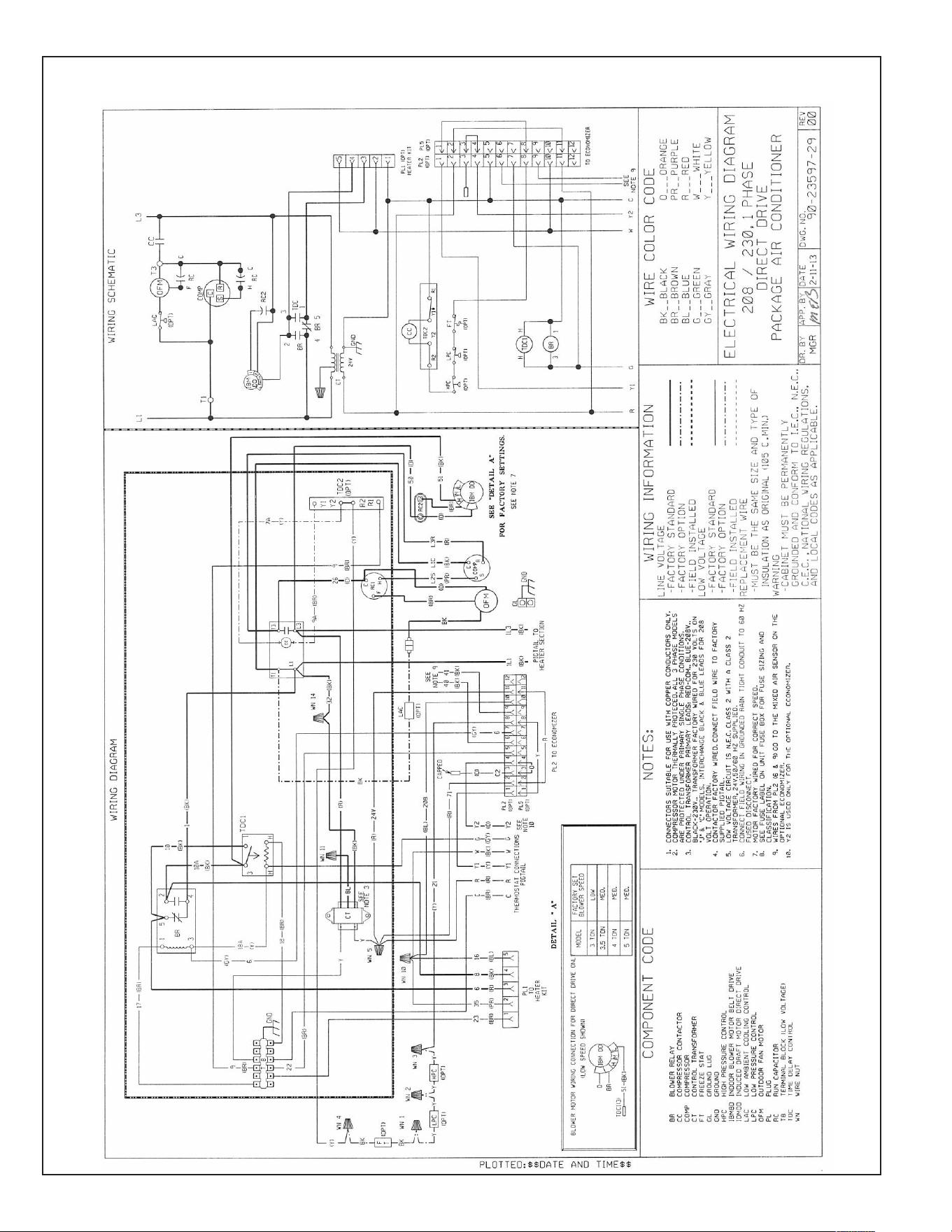
70
FIGURE 20
WIRING DIAGRAM
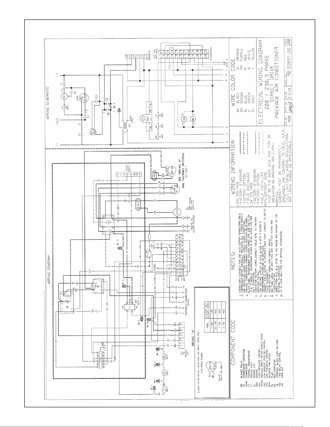
71
FIGURE 21
WIRING DIAGRAM
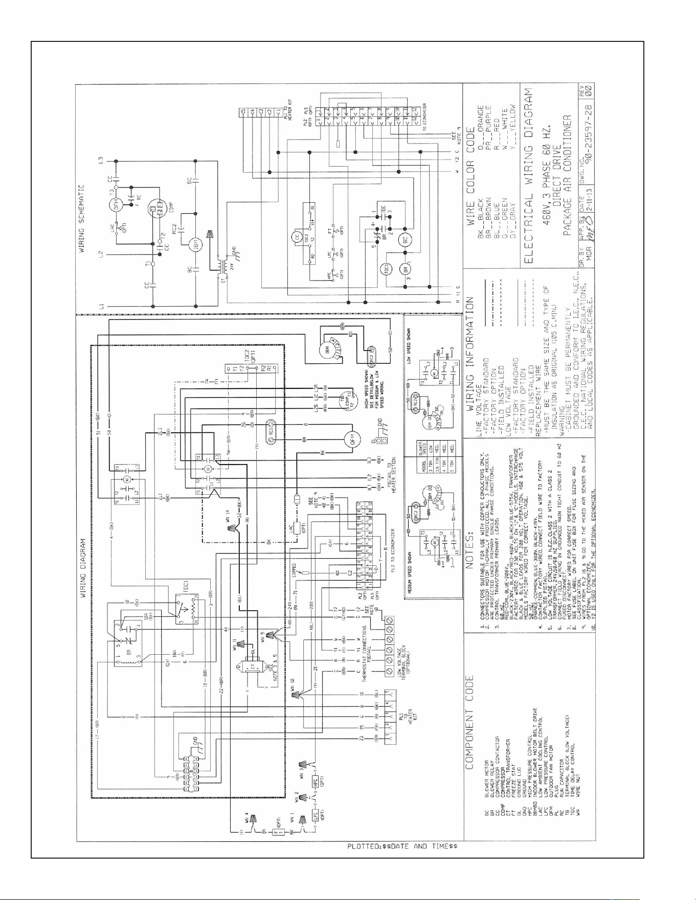
72
FIGURE 22
WIRING DIAGRAM
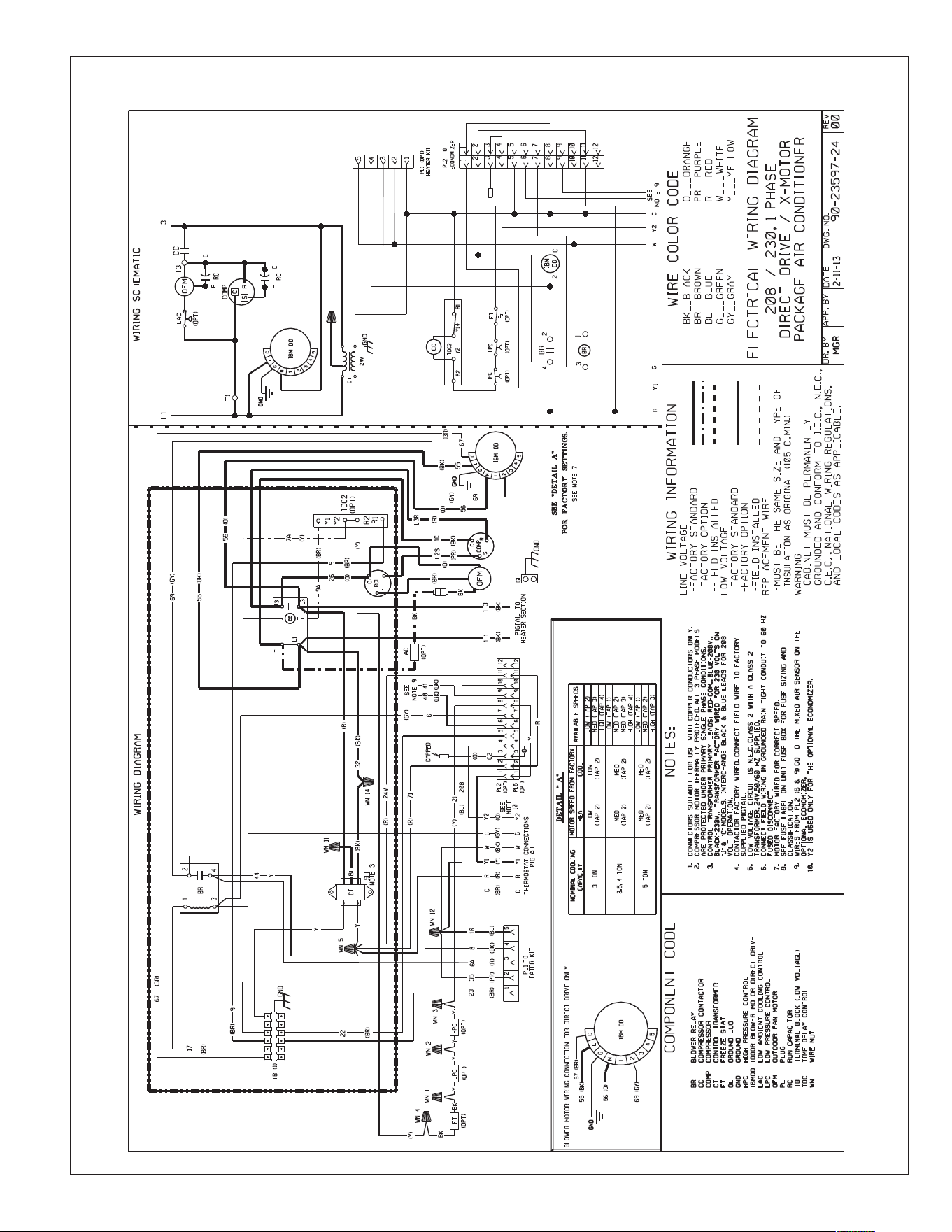
73
FIGURE 23
WIRING DIAGRAM
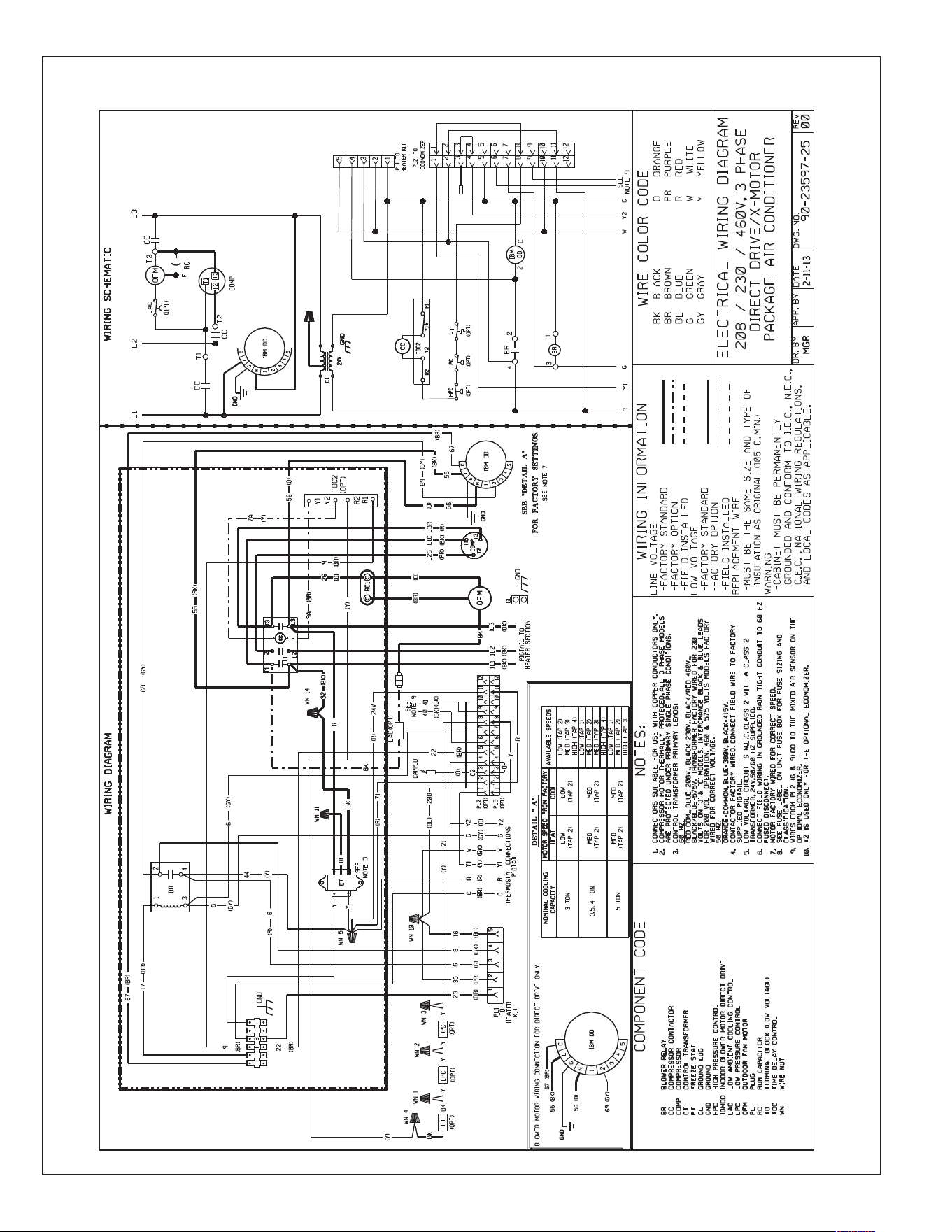
74
FIGURE 24
WIRING DIAGRAM
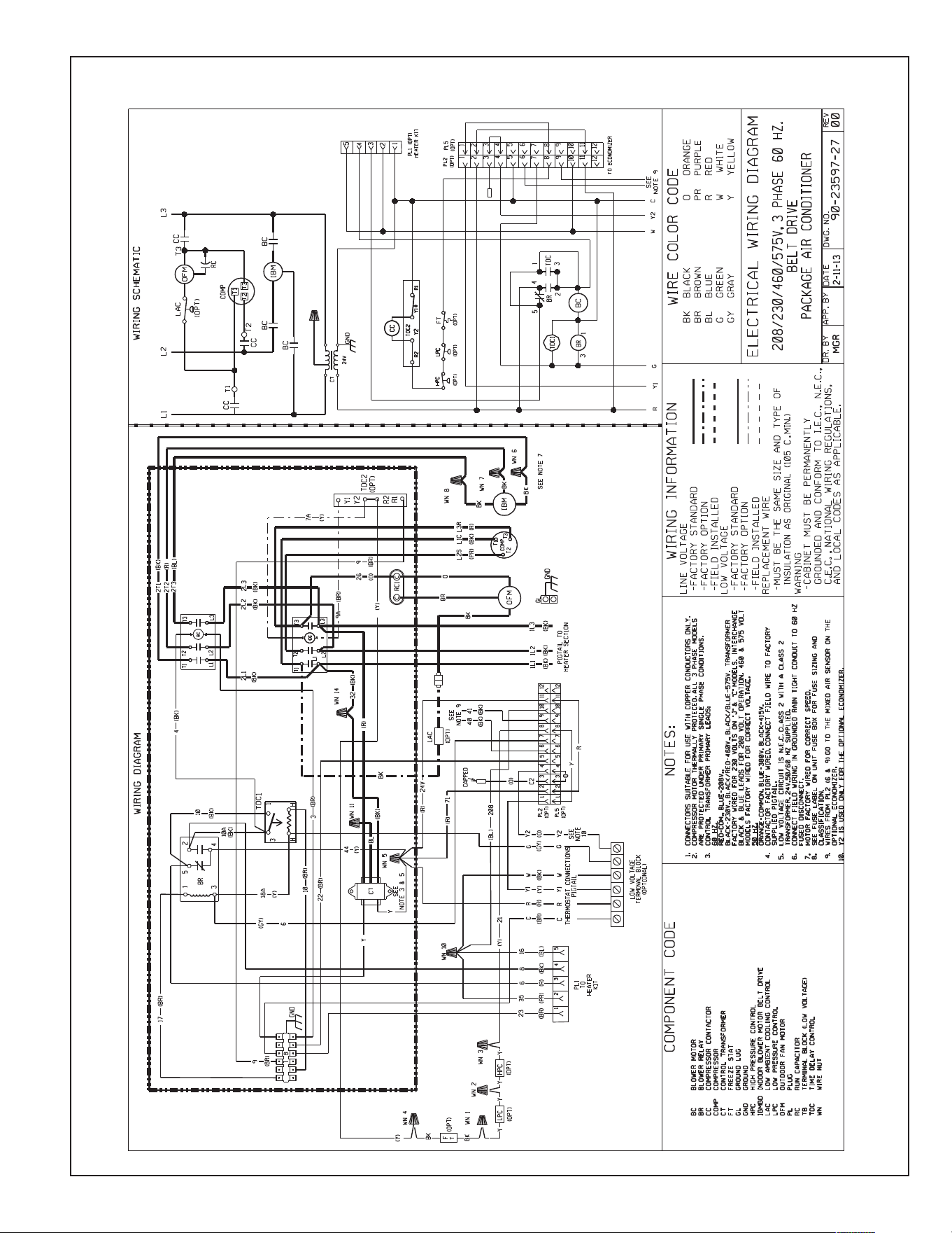
75
FIGURE 25
WIRING DIAGRAM
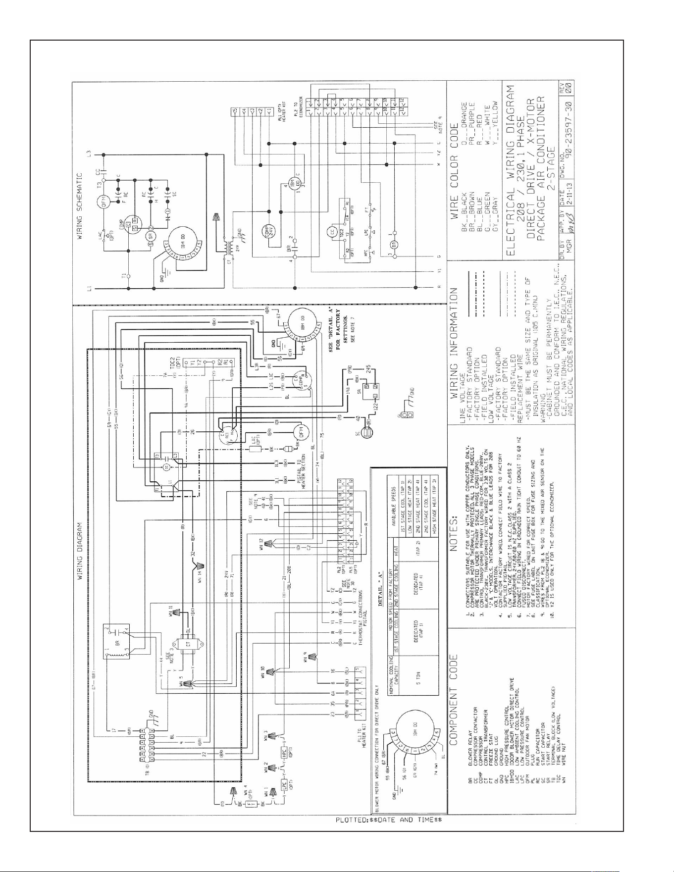
76
FIGURE 26
WIRING DIAGRAM
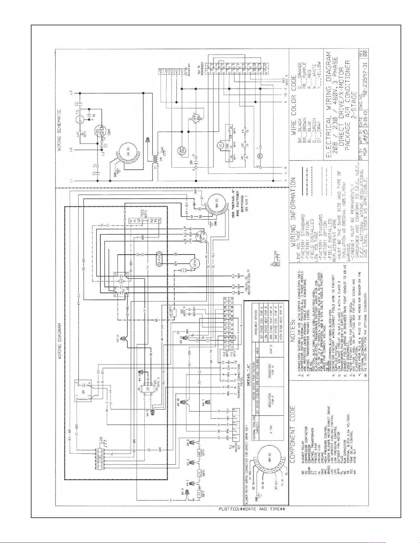
77
FIGURE 27
WIRING DIAGRAM
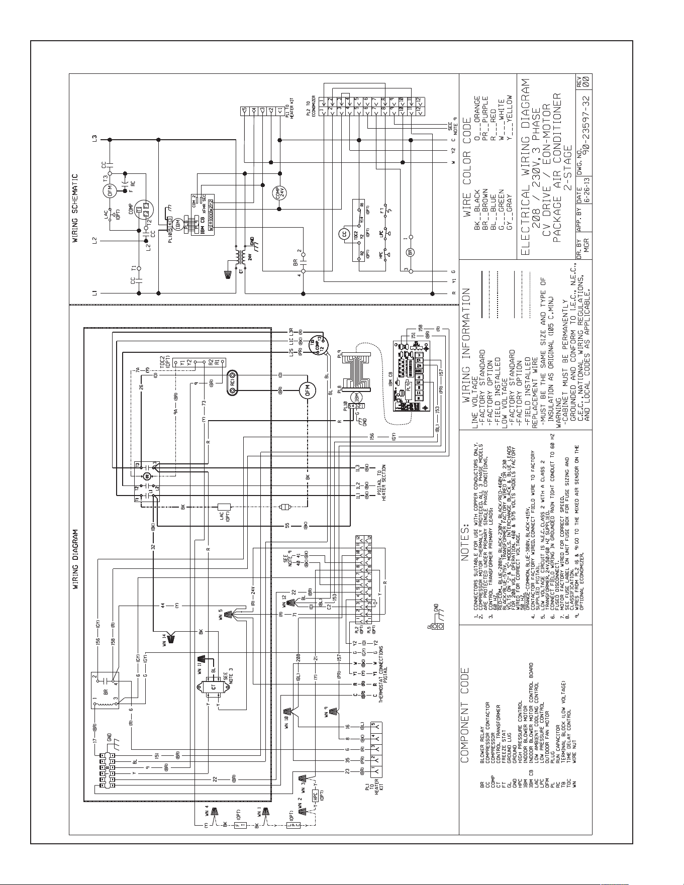
78
FIGURE 28
WIRING DIAGRAM
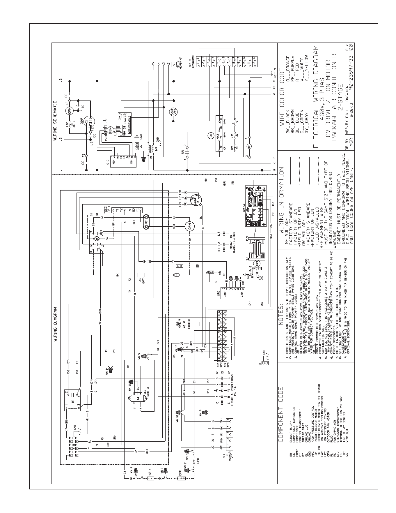
79
FIGURE 29
WIRING DIAGRAM
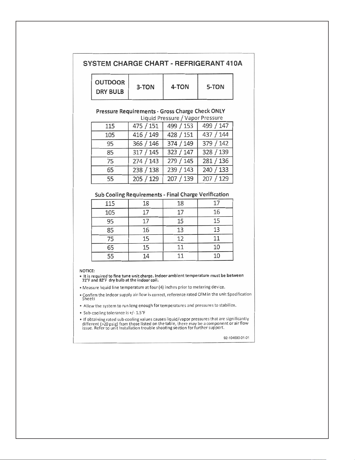
80
FIGURE 30
S
YSTEM CHARGE CHART
81
SYMPTOM POSSIBLE CAUSE REMEDY
U
nit will not run • Power off or loose electrical connection • Check for correct voltage at compressor contactor in control
b
ox
•
Thermostat out of calibration-set too high • Reset
•
Defective contactor • Check for 24 volts at contactor coil - replace if contacts are
open
•
Blown fuses • Replace fuses
•
Transformer defective • Check wiring-replace transformer
•
High pressure control open (if provided) • Reset-also see high head pressure remedy-The high pressure
c
ontrol opens at 610 PSIG
• Interconnecting low voltage wiring damaged • Replace thermostat wiring
C
ondenser fan runs, compressor • Run capacitor defective (single phase only) • Replace
d
oesn’t • Start relay defective (single phase on;y) • Replace
•
Loose connection • Check for correct voltage at compressor -
check & tighten all connections
• Compressor stuck, grounded or open motor winding, • Wait at least 2 hours for overload to reset.
o
pen internal overload. If still open, replace the compressor.
• Low voltage condition • At compressor terminals, voltage must be within 10% of rating
p
late volts when unit is operating
•
Low voltage condition • Add start kit components
Insufficient cooling • Improperly sized unit • Recalculate load
• Improper airflow • Check - should be approximately 400 CFM per ton.
• Incorrect refrigerant charge • Charge per procedure attached to unit service panel
•
Air, non-condensibles or moisture in system • Recover refrigerant, evacuate & recharge, add filter drier
• Incorrect voltage • At compressor terminals, voltage must be within 10% of rating
plate volts when unit is operating.
Compressor short cycles • Incorrect voltage • At compressor terminals, voltage must be ±10% of
nameplate marking when unit is operating.
• Defective overload protector • Replace - check for correct voltage
• Refrigerant undercharge • Add refrigerant
Registers sweat • Low evaporator airflow • Increase speed of blower or reduce restriction - replace air
filter
High head-low vapor pressures • Restriction in liquid line, expansion device or filter drier • Remove or replace defective component
• Flow check piston size too small • Change to correct size piston
• Incorrect capillary tubes • Change coil assembly
• TXV does not open • Replace TXV
High head-high or normal vapor • Dirty condenser coil • Clean coil
pressure - Cooling mode • Refrigerant overcharge • Correct system charge
• Condenser fan not running • Repair or replace
• Air or non-condensibles in system • Recover refrigerant, evacuate & recharge
Low head-high vapor pressures • Flow check piston size too large • Change to correct size piston
• Defective Compressor valves • Replace compressor
• Incorrect capillary tubes • Replace coil assembly
Low vapor - cool compressor - • Low evaporator airflow • Increase speed of blower or reduce restriction - replace air
iced evaporator coil filter
• Operating below 65°F outdoors • Add Low Ambient Kit
• Moisture in system • Recover refrigerant - evacuate & recharge - add filter drier
• TXV limiting refrigerant flow • Replace TXV
High vapor pressure • Excessive load • Recheck load calculation
• Defective compressor • Replace
Fluctuating head & vapor • TXV hunting • Check TXV bulb clamp - check air distribution on coil - replace
pressures TXV
• Air or non-condensate in system • Recover refrigerant, evacuate & recharge
Gurgle or pulsing noise at • Air or non-condensibles in system • Recover refrigerant, evacuate & recharge
expansion device or liquid line
DISCONNECT ALL POWER TO UNIT BEFORE SERVICING. CONTACTOR MAY BREAK ONLY ONE SIDE. FAILURE TO
SHUT OFF POWER CAN CAUSE ELECTRICAL SHOCK RESULTING IN PERSONAL INJURY OR DEATH.
WARNING
!
TROUBLE SHOOTING CHART

82

83

84
CM 0913