User Manual
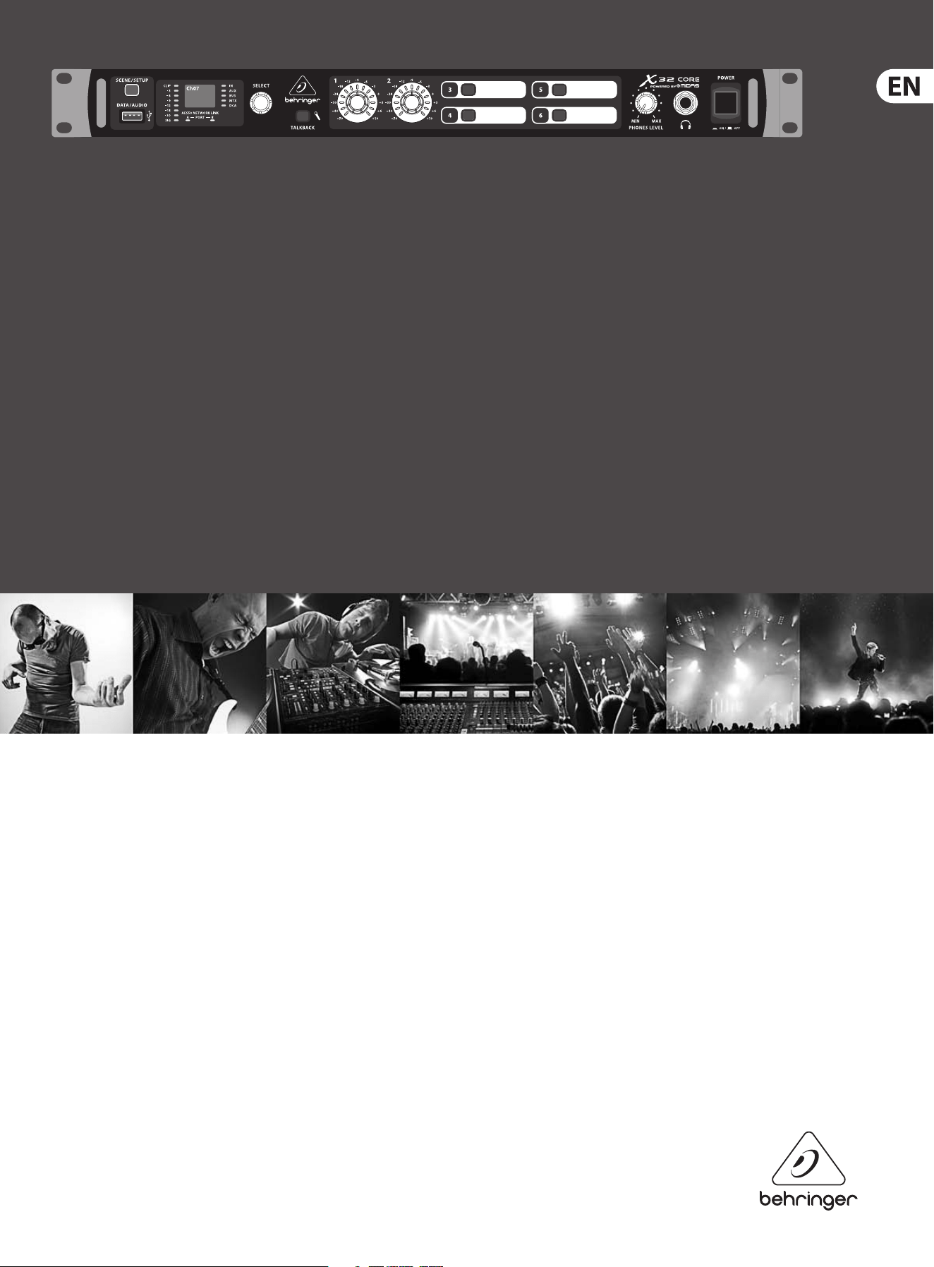
X32 CORE DIGITAL RACK MIXER
40-Input, 25-Bus Digital Rack Mixer with AES50 Networked Audio,
USB Audio Interface and iPad/iPhone Remote Control

2 X32 CORE DIGITAL RACK MIXER User Manual
Table of Contents
Important Safety Instructions ...................................... 3
Legal Disclaimer ............................................................. 3
Limited warranty ............................................................ 3
Introduction.................................................................... 4
1. Callouts ....................................................................... 5
2. Hookup ....................................................................... 6
3. Select Knob Functions .............................................. 8
4. FX Descriptions ........................................................ 10
5. Topic Guide .............................................................. 16
5.1 Firmware updates ............................................................. 16
5.2 Remote control .................................................................. 16
5.3 Recording a 2-track
directly with theconsole ....................................................... 16
5.4 Saving and recalling scenes .......................................... 16
5.5 How do I add one of the
8 internal eects to the sound? ........................................... 17
6. USB Interface Operation Guide .............................. 18
6.1 Conguring the X-USB card
for use in theconsole .............................................................. 18
6.2 Conguring the PC to
Interface withtheX-USB Card .............................................. 21
6.3 X-USB Specications........................................................23
7. Specications ...........................................................24
Block Diagram ..............................................................25
X32 MIDI Implementation ........................................... 26
3 X32 CORE DIGITAL RACK MIXER User Manual
Important Safety
Instructions
LEGAL DISCLAIMER
LIMITED WARRANTY
Terminals marked with this symbol carry
electrical current of su cient magnitude
to constitute risk of electric shock.
Use only high-quality professional speaker cables with
¼" TS or twist-locking plugs pre-installed. Allother
installation or modi cation should be performed only
by quali edpersonnel.
This symbol, wherever it appears,
alertsyou to the presence of uninsulated
dangerous voltage inside the
enclosure-voltage that may be su cient to constitute a
risk ofshock.
This symbol, wherever it appears,
alertsyou to important operating and
maintenance instructions in the
accompanying literature. Please read the manual.
Caution
To reduce the risk of electric shock, donot
remove the top cover (or the rear section).
No user serviceable parts inside. Refer servicing to
quali ed personnel.
Caution
To reduce the risk of re or electric shock,
do not expose this appliance to rain and
moisture. The apparatus shall not be exposed to dripping
or splashing liquids and no objects lled with liquids,
suchas vases, shall be placed on the apparatus.
Caution
These service instructions are for use
by quali ed service personnel only.
Toreduce the risk of electric shock do not perform any
servicing other than that contained in the operation
instructions. Repairs have to be performed by quali ed
servicepersonnel.
1. Read these instructions.
2. Keep these instructions.
3. Heed all warnings.
4. Follow all instructions.
5. Do not use this apparatus near water.
6. Clean only with dry cloth.
7. Do not block any ventilation openings. Install in
accordance with the manufacturer’s instructions.
8. Do not install near any heat sources such as
radiators, heat registers, stoves, or other apparatus
(including ampli ers) that produce heat.
9. Do not defeat the safety purpose of the polarized
or grounding-type plug. A polarized plug has two blades
with one wider than the other. A grounding-type plug
has two blades and a third grounding prong. The wide
blade or the third prong are provided for your safety. Ifthe
provided plug does not t into your outlet, consult an
electrician for replacement of the obsolete outlet.
10. Protect the power cord from being walked on or
pinched particularly at plugs, convenience receptacles,
and the point where they exit from the apparatus.
11. Use only attachments/accessories speci ed by
themanufacturer.
12. Use only with the
cart, stand, tripod, bracket,
or table speci ed by the
manufacturer, orsold with
the apparatus. When a cart
is used, use caution when
moving the cart/apparatus
combination to avoid
injury from tip-over.
13. Unplug this apparatus during lightning storms or
when unused for long periods of time.
14. Refer all servicing to quali ed service personnel.
Servicing is required when the apparatus has been
damaged in any way, such as power supply cord or plug
is damaged, liquid has been spilled or objects have fallen
into the apparatus, the apparatus has been exposed
to rain or moisture, does not operate normally, or has
beendropped.
15. The apparatus shall be connected to a MAINS socket
outlet with a protective earthing connection.
16. Where the MAINS plug or an appliance coupler is
used as the disconnect device, the disconnect device shall
remain readily operable.
17. Correct disposal of this
product: This symbol indicates
that this product must not be
disposed of with household
waste, according to the WEEE
Directive (2002/96/EC) and
your national law. This product
should be taken to a collection center licensed for the
recycling of waste electrical and electronic equipment
(EEE). The mishandling of this type of waste could have
a possible negative impact on the environment and
human health due to potentially hazardous substances
that are generally associated with EEE. At the same time,
your cooperation in the correct disposal of this product
will contribute to the e cient use of natural resources.
For more information about where you can take your
waste equipment for recycling, please contact your local
city o ce, or your household waste collection service.
MUSIC Group accepts no liability for any loss which
may be su ered by any person who relies either
wholly or in part upon any description, photograph,
or statement contained herein. Technical speci cations,
appearances and other information are subject to
change without notice. All trademarks are the property
of their respective owners. MIDAS, KLARK TEKNIK,
TURBOSOUND, BEHRINGER, BUGERA and DDA are
trademarks or registered trademarks of MUSIC Group IP
Ltd. © MUSIC Group IP Ltd. 2014 All rights reserved.
For the applicable warranty terms and conditions
and additional information regarding MUSIC Group’s
Limited Warranty, please see complete details online at
music-group.com/warranty.

4 X32 CORE DIGITAL RACK MIXER User Manual
Introduction
Welcome to the X32 CORE user manual! After years of intense development,
weare proud to oer a mixer that combines tremendous power and exibility
with a very user-friendly layout and intuitive workow that allow you to get
up-and-running right away.
The X32 CORE is a robust-yet-streamlined mixer that features all of the basic
functionality and processing of BEHRINGER's agship X32 console in a smaller
form factor. When paired with our S16 digital stagebox and either the X32-Mix
iPad app or X32-Edit PC/Mac editor, the CORE becomes the centerpiece of a
highly-exible mixing system for both portable and xed-install applications.
Dual AES50 Ethernet jacks that employ KLARK TEKNIK SuperMAC technology
contribute 96 x 96 signals to the total count of 168 x 168 accessible sources and
destinations. The ability to save and recall entire scenes makes set or program
changes quick and simple. A front panel USB connector enables system data to be
stored or a board mix to be recorded directly to external ash or hard drives.
A virtual FX rack oers 8 true-stereo (16 mono) multi-eects processors,
with39FX models that eliminate the need for any additional outboard gear.
4high-quality eects such as delay, chorus and reverb can run concurrently with
8channels of 31-band graphic equalization.
The built-in USB interface card enables streaming of up to 32 tracks to and from a
computer for recording, mixing and mastering purposes.
Continue through this user manual to learn all about the functionality that this
powerful mixer has to oer! We also recommend that you check behringer.com to
make sure you have the latest rmware installed as we release frequent updates.
5 X32 CORE DIGITAL RACK MIXER User Manual
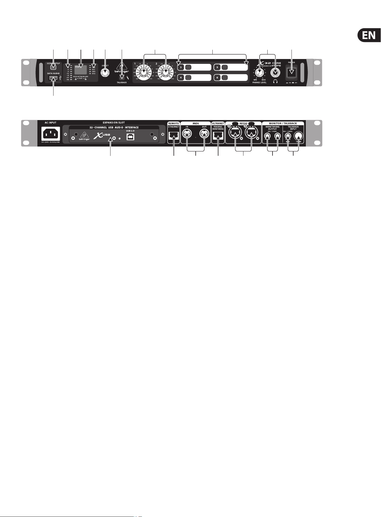
1. Callouts
(1) (3) (4) (5) (6) (7) (8) (9) (10) (11)
(2)
(12) (13) (15) (16) (17)(14) (18)
(1) SCENE/SETUP button toggles between Scenes Recall (green LED) and
Channel Selector mode (LED o) with a short press. Hold the button to
enter Setup Mode (green LED) and press the button again to exit Setup
Mode. The LED turns red to indicate access on attached DATA/AUDIO
USB media.
(2) DATA/AUDIO input allows connection of USB ashdrives for rmware
updates, loading/saving scenes and show les, and playing back or
recording WAV les.
(3) METER displays the input level of the selected channel.
(4) DISPLAY shows the channel name and icon, scene name, or setup
pageinformation.
(5) CHANNEL TYPE LEDs indicate which type of channel is currently selected.
(6) SELECT knob navigates the display menus and edits setup parameters.
Seethe SELECT Knob Functions section for details.
(7) TALKBACK button engages the external Talkback mic input on the
rear panel. Details of the routing and operation can be dened on the
monitoring preferences page of the control software.
(8) USER ASSIGNABLE ENCODERS adjusts a predened variable parameter in
the software. Function to be dened in the control software.
(9) USER ASSIGNABLE BUTTONS toggles a predened on/o parameter in
the software. Function to be dened in the control software.
(10) PHONES output and level allow audio to be monitored directly from
the unit. Details of the audio content can be adjusted in the monitoring
preferences page of the control software. While in Channel Select Mode,
push the Select encoder to toggle Solo on and o.
(11) POWER button turns the unit on and o.
(12) X-USB interface card allows up to 32 channels of bidirectional audio to be
transmitted to and from a computer.
(13) ETHERNET connector allows full OSC-based remote control of the X32 CORE.
(14) MIDI IN/OUT allows the unit to send and receive MIDI commands via
standard 5-pin DIN cables.
(15) ULTRANET connector sends 16 channels of audio to a P16
monitoringsystem.
(16) AES50 A and B connectors allow 96 channels of bidirectional audio for
connection to S16 digital snakes or other X32 family products. The front
panel LEDs will light green to indicate proper sync, light red to indicate
a sync error, and remain unlit when no connection is present. Shielded
CAT-5e cable should always be used for AES50 connections between X32
and S16 units.
(17) MONITORING OUTPUT jacks allow connection of monitor speakers via
balanced or unbalanced ¼" cables.
(18) TALKBACK input accepts a dynamic microphone via ¼" TRS jack. Adjust the
gain with the adjacent TRIM knob.
6 X32 CORE DIGITAL RACK MIXER User Manual
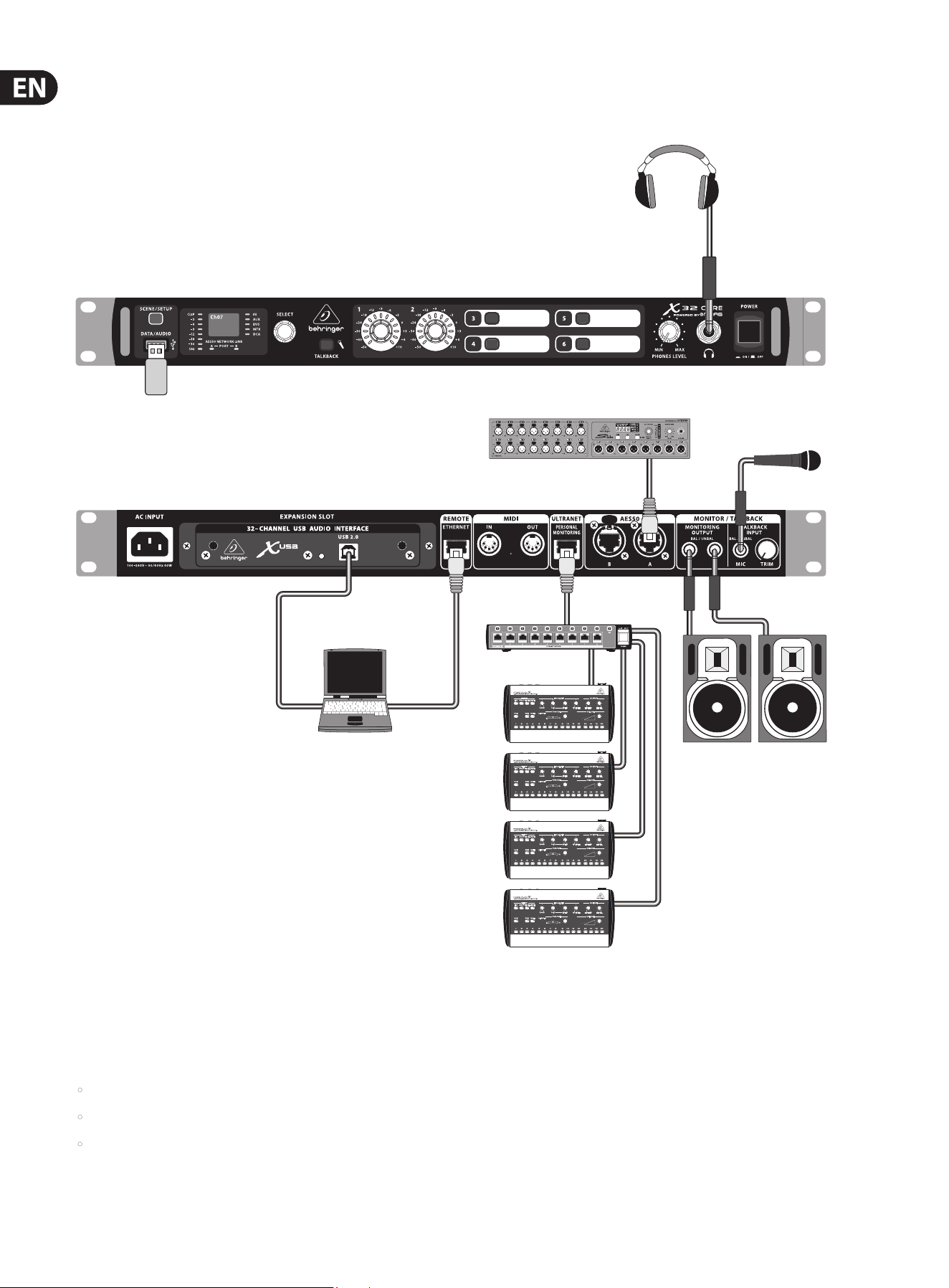
2. Hookup
Basic Connections
TRS
TRS
P16D
B3031A Studio monitors
S16 Digital Snake
USB drive for rmware updates, loading
Scenes and playing/recording WAV les
P16M
TRS
TRS
HPX6000
Cabling for all AES50 connections between X32 and S16 stageboxes:
• Shielded CAT-5e cable
• Ethercon terminated cable ends
• Maximum cable length 100 meters (330 feet)
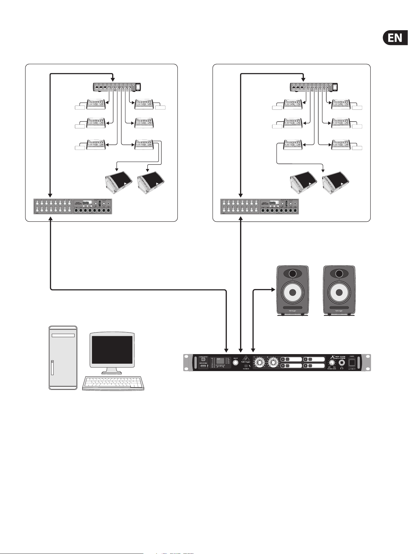
7 X32 CORE DIGITAL RACK MIXER User Manual
Multiple Stage Setup with X32 CORE, S16 Snake and P16 Personal Monitor System
P16-D Distributor
Keyboards Percussion
Percussionist
2nd Guitarist
Background Vocal 1
Spare
Background Vocal 2
Background Vocal 3
IEM IEM
IEM IEM
IEM
P16-D Distributor
Drummer
F1320D Active oor monitors
Vocal 1
POWERPLAY P16-M Digital Personal Mixers
IEM
Bass Player
Guitarist
Voc 1 Floor wedges
Vocal 1
Keyboardist
Phones
IEM
IEM
Control room with PC application to run both stage setups from one
location through the X32 CORE
K8 Active Studio Monitors
AES50
Supermac
AES50
Supermac
Analog balanced TRS
P16
Ultranet
P16
Ultranet

8 X32 CORE DIGITAL RACK MIXER User Manual
3. Select Knob Functions
The SELECT knob serves several functions on the X32 CORE. The following table describes the SELECT knob behavior in each of the available scenarios.
Action
Functional Description
Channel Select Mode (SCENE/SETUP button LED is o)
Display >Selected channel number
>Input source
>Channel icon and color
>Nickname
Short press Toggles the selected channel to SOLO on/o
> Channel signal will be sent to Monitoring L/R outputs on rear panel and
Phones output on front panel
> Exact behavior depends on settings in Monitoring page
(remotecontrolled via editing software)
Rotate Immediately selects the desired channel
(input, aux in, FX return, bus, matrix, main or DCA)
>The Channel Type LEDs [5] will follow the selection.
> Note that the X32 CORE Channel Selector will skip all channels, setting
the display color to ’black’ or ’o’.
Long press Clears all active channel solos
Scene Select Mode (accessed by pressing the SCENE/SETUP button so that the LED is green)
Display >“Scene” in bold
>Current scene number
>Next scene number and name (small) to be loaded on GO
Short press Recalls the selected Scene from X32 internal memory “GO”
> behavior depends on Scene settings/preferences (remote controlled via
editing software)
> Scene safes can only be set/reset remotely
> Scenes/Shows from USB drives can only be accessed remotely
>A complete show can be loaded from an attached USB drive into the
internal memory using Setup Mode
Rotate Preselects the next Scene
Setup Mode (accessed by pressing and holding the SCENE/SETUP button so that the LED is green)
Rotate and press Select and enter the Setup pages:
1. Load Show
2. Contrast
3. LEDs
4. Clock Rate
5. Sync
6. IP Address
7. IP (Subnet) Mask
8. IP Gateway
9. Lock
1. Load Show Load show from root directory of attached USB drive
>display 3 rows:
-Load Show
-Exit
-Show Files
>Exit leads back to Setup Mode root level
>Turn clockwise to scroll through a list of show les found in USB root
directory, push to load selected show and return to Setup Mode root level
2. Contrast LCD contrast
> Rotate to adjust 0-100
> Press to conrm and exit

9 X32 CORE DIGITAL RACK MIXER User Manual
Action
Functional Description
3. LEDs LED brightness
> Rotate to adjust 0-100
> Press to conrm and exit
4. Clock Rate Select the internal Sample Clock Rate
> Rotate to adjust 44.1 or 48 kHz (change requires to reboot the X32 CORE)
> Press to conrm and exit
5. Sync Choose Clock Synchronization source
> Rotate to select INT (internal), AES50 (Port) A, or AES50 (Port) B
> Press to conrm and exit
6. IP Address Select the IP Address for X32 CORE
> Rotate to adjust the rst triplet (0-255)
> Press to conrm
> Rotate to adjust the second triplet (0-255)
> Press to conrm
> Rotate to adjust the third triplet (0-255)
> Press to conrm
> Rotate to adjust the fourth triplet (0-255)
> Press to conrm and exit
7. IP Mask Select the IP Subnet Mask for X32 CORE
> Rotate to adjust the rst triplet (0-255)
> Press to conrm
> Rotate to adjust the second triplet (0-255)
> Press to conrm
> Rotate to adjust the third triplet (0-255)
> Press to conrm
> Rotate to adjust the fourth triplet (0-255)
> Press to conrm and exit
8. IP Gateway Select the IP Gateway for X32 CORE
> Rotate to adjust the rst triplet (0-255)
> Press to conrm
> Rotate to adjust the second triplet (0-255)
> Press to conrm
> Rotate to adjust the third triplet (0-255)
> Press to conrm
> Rotate to adjust the fourth triplet (0-255)
> Press to conrm and exit
9. Lock Locks the X32 CORE
>Display “Lock Cancel”
>Press to cancel locking
> Rotating clockwise turns the display from Green to Red backlight and
shows “LOCKED”
> Press and hold the SCENE/SETUP button for 5 seconds in order to
exit Locked mode and get back to the standard Channel Select mode
(showingthe last selected channel)
10 X32 CORE DIGITAL RACK MIXER User Manual
4. FX Descriptions
FX Descriptions
Here is a list and brief description of the eects available on the X32 CORE.
WhenStereoand Dual versions of an eect are oered, use the Stereo version
when the left and right signal are to be altered together (e.g. on linked stereo
channels or buses), or Dual when you want to dial dierent settings for the left
and right signal. Assignment and editing of eects parameters is done via the
X32-Edit or X32-Mix applications.
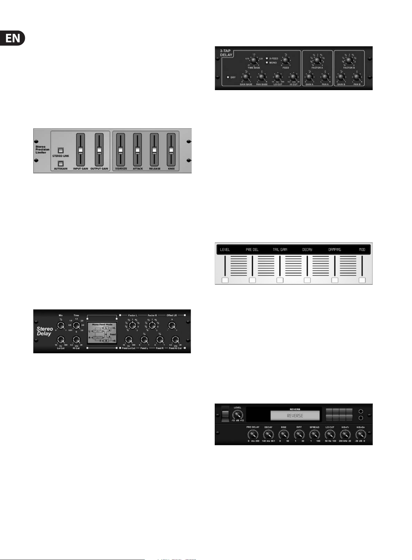
Stereo Precision Limiter
Stereo Precision Limiter allows you to set a precise volume limit,
ensuringdistortion-free, optimal signal integrity. Use X32’s Stereo Precision
Limiter to boost quiet signals or preventing clipping while preserving the level of
“hot”signals.
AUTOGAIN activates an additional long-term gain correction, allowing automatic
gain scaling of varying input level ranges. STEREO LINK applies limiting to both
channels equally when activated. INPUT GAIN provides up to 18 dB of gain to
the input signal prior to limiting. OUTPUT GAIN sets the nal gain level of the
processed signal. SQUEEZE adds compression to the signal to add punch and a
slight distortion depending on the amount you dial in. ATTACK sets the attack
time, ranging from 0.05 mS to 1 mS. RELEASE adjusts the release time from
0.05mS to 1.04 seconds. KNEE adjusts the soft limiting threshold point from hard
limiting (0 dB) to maximum soft limiting (10 dB).
Stereo Delay
Stereo Delay provides independent control of left and right delay (echo)
timesand features high and low pass lters for enhanced tone shaping of the
delayed signals. Use the Stereo Delay to give your mono signals a wide presence
in the stereo eld.
The MIX control lets you blend the source signal and the delayed signal.
TIMEadjusts the master delay time up to three seconds. LO CUT adjusts the low
frequency cut, allowing lower frequencies to remain unaected by the delay.
HI CUT adjusts the high frequency cut, allowing higher frequencies to remain
unaected by the delay. FACTOR L sets the delay on the left channel to rhythmic
fractions of the master delay time. FACTOR R sets the delay on the right channel
to rhythmic fractions of the master delay time. OFFSET LR adds a delay dierence
between the left and right delayed signals. The FEED LO CUT/HI CUT adjusts lters
in the feedback paths. FEED L and FEED R control the amount of feedback for
the left and right channels. MODE sets the feedback mode: Mode ST sets normal
feedback for both channels, X crosses feedbacks between left and right channels.
M creates a mono mix within the feedback chain.
Triple Delay
Sometimes called a 3-Tap Delay, the Triple Delay provides three delay stages with
independent frequency, gain, and pan controls. Create time-based echo eects
with the Triple Delay to increase the sense of stereo separation.
TIME BASE sets the master delay time, which is also the delay time for the rst
stage. GAIN BASE sets the gain level of the rst stage of the delay. PAN BASE sets
the position of the rst delay stage in the stereo eld. LO CUT sets the frequency
at which the source signal can begin passing through the delay. HI CUT sets the
frequency at which the source signal no longer passes through the delay. X-FEED
indicates that stereo cross-feedback of the delays is active. MONO activates a mono
mix of both channels for the delay input. FEED adjusts the amount of feedback.
FACTOR A controls the amount of delay time in the second stage of the delay.
GAIN A controls the gain level of the second delay stage. PAN A sets the position of
the second delay stage in the stereo eld. FACTOR B controls the amount of delay
time in the third stage of the delay. GAIN B controls the gain level of the third delay
stage. PAN B sets the position of the third gain stage in the stereo eld.
Ambience
Ambience creates a customizable virtual acoustic space in which to place the
elements of a mix. Use Ambience to add warmth and depth without coloring the
direct sound. (Inspired by the Lexicon Ambience Algorithm)
PRE DELAY sets the time before the reverb follows the source signal. DECAYadjusts
the time it takes for the reverb to completely dissipate. SIZEcontrols the room
size emulation. DAMPING controls the high frequency decay within the reverb
tail. DIFFUSE controls the initial echo density. Level sets the volume output of the
aected signal. LO CUT adjusts the low frequency cut, allowing lower frequencies
to remain unaected by the reverb. HI CUT adjusts the high frequency cut,
allowing higher frequencies to remain unaected by the reverb. MOD adjusts the
level of reverb decay modulation. TAIL GAIN adjusts the volume of the reverb tail.
Reverse Reverb
Reverse Reverb takes the trail of a reverb, turns it around, and places it in front
of the sound source. Use the swelling crescendo of the Reverse Reverb to add an
ethereal quality to vocal and snare tracks. (Inspired by the Lexicon 300/480L)
Adjusting the PRE DELAY knob adds up to 200 milliseconds of time before the
reverb follows the source signal. The DECAY knob adjusts the time it takes for
the reverb to completely dissipate. RISE controls how quickly the eect builds
up. DIFF(USION) controls the initial reection density. SPREAD controls how the
reection is distributed through the envelope of the reverb. The LO CUT knob sets
a low frequency beneath which the source signal will not pass through the reverb.
The HiSvFr/HiSvGn knobs adjust a Hi-Shelving lter at the input of the reverb eect.
11 X32 CORE DIGITAL RACK MIXER User Manual
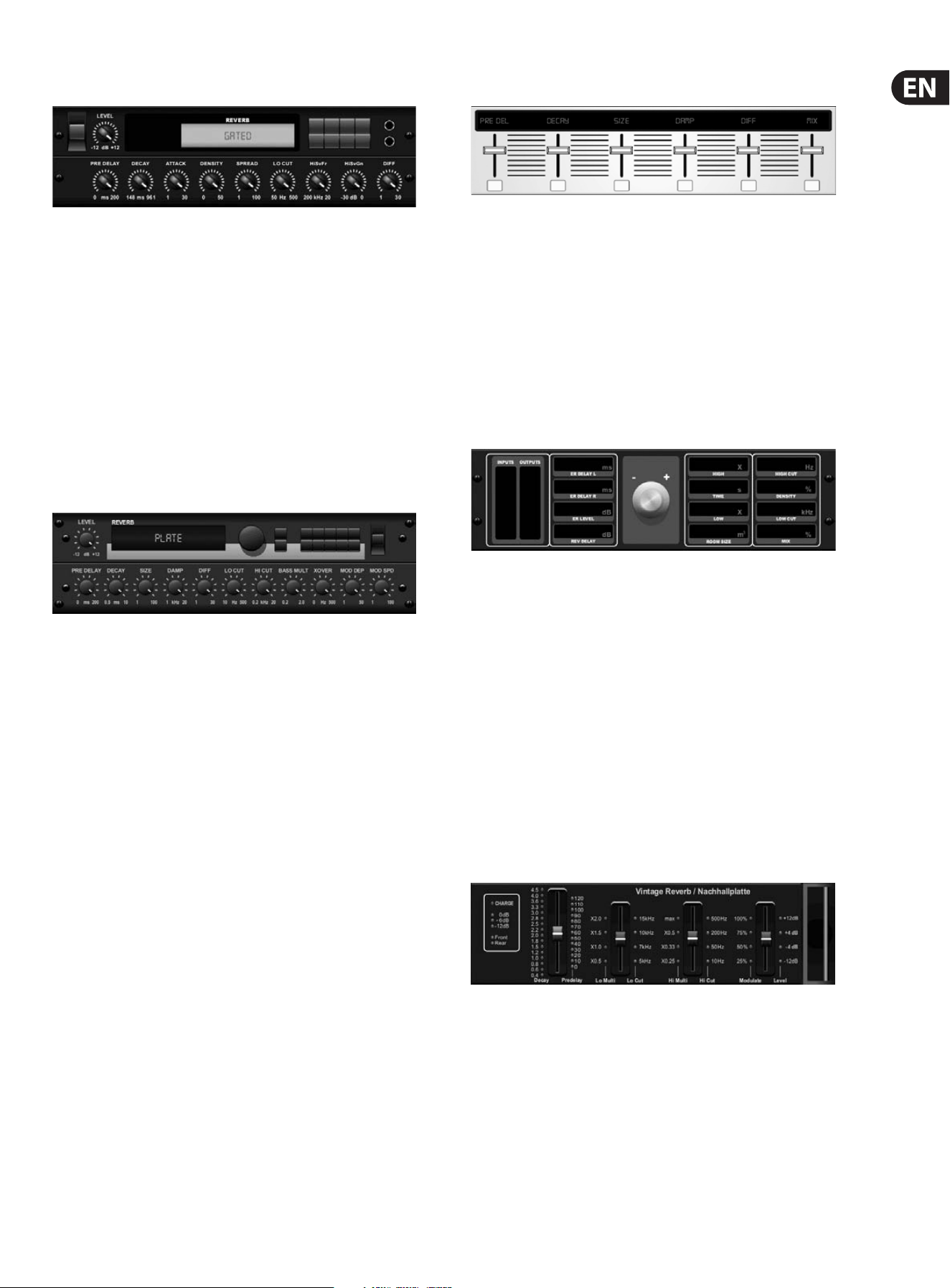
Gated Reverb
This eect was originally achieved by combining a reverb with a noise gate.
Ourgated reverb creates the same impression by a special shaping of the reverbtail.
Gated Reverb is especially eective for creating a 1980s-style snare sound or to
enlarge the presence of a kick drum. (Inspired by the Lexicon 300/480L)
PRE DELAY controls the amount of time before the reverberation is heard following
the source signal. DECAY controls the amount of time it takes for the reverb to
dissipate. ATTACK controls how fast the reection density builds up. DENSITY shapes
the reverb decay tail. The higher the density, the greater the number of sound
reections. SPREAD controls how the reection is distributed through the envelope
of the reverb. The LO CUT knob sets the frequency beneath which the source signal
will not pass through the reverb. The HiSvFr/ HiSvGn knobs adjust a Hi-Shelving lter
at the input of the reverb eect. DIFF(USION) controls the initial reection density.
Plate Reverb
A plate reverb was originally created by sending a signal through a transducer
to create vibrations on a plate of sheet metal which were then picked up as an
audio signal. Our algorithm simulates that sound with high initial diusion and a
bright colored sound. X32’s Plate Reverb will give your tracks the sound heard on
countless hit records since the late 1950s. (Inspired by the Lexicon PCM-70)
PRE DELAY controls the amount of time before the reverberation is heard
following the source signal. DECAY controls the amount of time it takes for the
reverb to dissipate. SIZE adjusts the size of the virtual room created by the reverb
eect. The DAMP knob adjusts the decay of high frequencies within the reverb
tail. DIFF(USION) controls the initial reection density. The LO CUT knob sets the
frequency beneath which the source signal will not pass through the reverb.
The HI CUT knob sets the frequency above which the source signal will not pass
through the reverb. The BASS MULT(IPLIER) knob adjusts the decay time of the
bass frequencies. XOVER controls the crossover point for bass. MOD DEPTH and
SPEED control the intensity and speed of the reverb tail modulation.
Hall Reverb
Classic Hall Reverb simulates the reverberation that occurs w hen sound is
recorded in medium to large-sized concert halls. Use the Hall Reverb to give your
mix a lush, three-dimensional quality that will make your performance sound
larger than life. (Inspired by the Lexicon Hall)
The PRE DELAY slider controls the amount of time before the reverberation is
heard following the source signal. DECAY controls the amount of time it takes for
the reverb to dissipate. SIZE controls the perceived size of the space being created
by the reverb eect. The DAMP slider adjusts the decay of high frequencies within
the reverb tail. DIFF(usion) controls the initial reection density. SHAPE adjusts
the contour of the reverberation envelope.
Vintage Room
Vintage Room simulates the reverberation that occurs when sound is recorded in
a small room. When you want to add a bit of warmth and just a touch of reverb,
X32’s Vintage Room breathes life into close-miced guitar and drum tracks.
(Inspired by the Quantec QRS)
The VU meter displays the input and output levels. Set the early reection times
for the left and right channel with ER DELAY L and ER DELAY R. ER LEVEL sets the
loudness of the early reection level. REV DELAY controls the amount of time before
the reverberation is heard following the source signal. HI/LOW MULTIPLY adjusts the
decay time of the high and bass frequencies. TIME shows the duration of the reverb
eect. ROOM SIZE adjusts the size of the room eect being created incrementally
from small to large. HIGH CUT sets the frequency above which the source signal
does not pass through the reverb. DENSITY manipulates the reection density in the
simulated room. (This slightly changes the reverb decay time). LOW CUT sets the
frequency below which the source signal does not pass through the reverb.
Vintage Reverb
Based on the legendary EMT250, X32’s Vintage Reverb delivers shimmering
bright reverb that won’t drown out or overpower your live or recorded tracks.
UseVintage Reverb to sweeten vocals and snare drums without sacricing clarity.
When layer 1 is selected, the rst slider on the left sets the reverb time from
4milliseconds to 4.5 seconds. Slider 2 controls the low frequency multiplier
decay time. Slider 3 controls the high frequency multiplier decay time. Slider 4
controls the amount of modulation in the reverb tail. When layer two is selected,
slider1adjusts the pre delay. Slider 2 selects the low cut frequency. Slider 3
selects the Hi Cut frequency. Slider 4 adjusts the output level of the reverb.
12 X32 CORE DIGITAL RACK MIXER User Manual
When Layer 1 is selected, the far left encoder push button allows you to select
between virtual front and rear outputs. Rear is suitable for drums due to it being
less reective. Front is well-suited for vocals and other dynamic instruments.
TheVintage button enables the simulation of the input transformers.
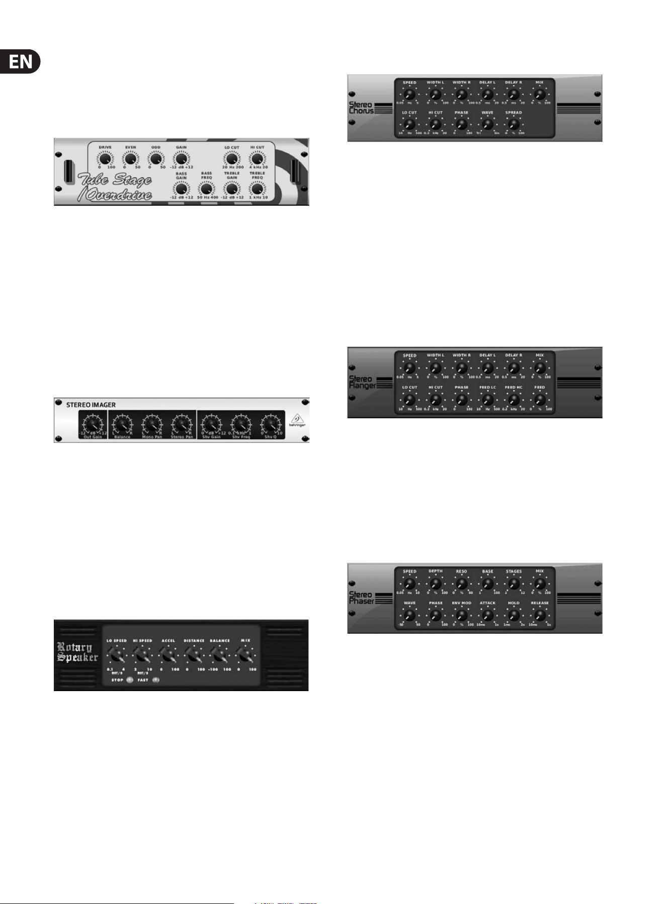
Stereo/Dual Tube Stage/Overdrive
Tube Stage/Overdrive is a versatile eect capable of emulating a variety of
modern and classic tube preamps. Available in stereo and dual-mono versions,
use Tube Stage/Overdrive to dial in warm and fuzzy sounds from subtle to
fullysaturated.
DRIVE adjusts the amount of harmonics being driven by the eect. EVEN and ODD
adjust the amount of even and odd harmonics. GAIN adjusts the output gain of
the eect. LO CUT sets the input frequency below which the source signal will not
pass through the eect. HI CUT sets the input frequency above which the input
signal will not pass through the eect. BASS GAIN/FREQ adjust a low shelving
lter at the output of the eect. TREBLE GAIN/FREQ adjust a high shelving lter at
the output of the eect.
Stereo Imager
A Stereo Imager is typically used to control the placement of a signal within the
stereo eld during mixdown or mastering. Modeled after the BEHRINGER Edison
rack unit, X32’s Stereo Imager will lend a professional quality to your live and
recording performances.
The BALANCE knob allows you to emphasize the mono or stereo components
of the input signal. The mono and stereo signals can be panned independently
with the MONO PAN and STEREO PAN knobs. OUT GAIN is used to compensate for
level changes resulting from the eect. The phase can also be shifted using the
shelving knobs. Select the frequency and bandwidth (Q) using the corresponding
knobs, then adjust the gain with the SHV GAIN knob.
Rotary Speaker
Rotary Speaker emulates the sound of a Leslie rotating speaker. X32’s Rotary
Speaker provides more exibility than its electro-mechanical counterpart,
andcan be used with a variety of instruments, and even vocals, to create a
whirling, psychedelic eect.
The LO SPEED and HI SPEED knobs adjust the rotational speed of the
SLOWandFAST Speed selection, and can be toggled with the FAST button.
TheACCEL(eration) knob adjusts how quickly the speed increases and decreases
from the Slow mode to the Fast mode. The rotation eect can also be disengaged
with the STOP button, which will stop the movement of the speakers.
DISTANCE adjusts the distance between the Rotary speakers and the
virtualmicrophone.
Chorus / Stereo Chorus
Chorus samples the input, slightly detunes it and mixes it with the original
signal to produce a somewhat thicker, shimmering sound. Use it to thicken up
background vocals, or to double the sound of brass and woodwind instruments.
Where as DELAY L/R set the total amount of delay for the left and right channel,
WIDTH determines the amount of modulated delay. SPEED sets the modulation
speed. MIX adjusts the balance of the dry and wet signals. You can further sculpt
the sound by trimming some of the low and high end from the eected signal
with the LO and HI CUT knobs. Additionally, the PHASE knob can tweak the
phase oset of the LFO between left and right channel and the SPREAD knob
adjusts how much of the left channel is mixed into the right and vice versa.
Finally,theWAVE knob blends between the “Danish-style” digital triangular
chorus sound and the classic analog sine wave.
Flanger / Stereo Flanger
The Flanger emulates the phase-shifting sound (comb-ltering)
originallycreated by applying pressure against the ange of the reel on a tape
recorder. This eect creates a unique “wobbly” sound that is quite dramatic when
used on vocals and instruments.
The controls of this eect are nearly identical to the Chorus eect block.
Additionally, the FEEDBACK can be adjusted with positive and negative amounts
and also band-limited with the FEED HC (high-cut) and FEED LC (low-cut) knobs.
Stereo Phaser
A Stereo Phaser, or phase shifter, applies multiple STAGES of modulated lters to
the input signal to create a “notch” in the frequency response, and then applies
a MIX with the original for a “swirling” eect. Use X32’s Stereo Phaser to add a
“spaced-out” sound to vocal or instrument tracks.
SPEED adjusts the LFO rate and DEPTH sets the LFO modulation depth.
The BASE knob adjusts the frequency range of the modulated lters.
Theresonance is adjusted with the RESO knob. The WAVE knob shapes the
symmetry of the LFO waveform and PHASE dials in an LFO phase dierence
between the left and right channel. The modulation source can also be the signal
envelope, which produces vowel-like opening and closing tones. The ENV MOD
knob adjusts how much this eect takes place (positive and negative modulation
is possible), and the ATTACK, HOLD and RELEASE knobs all tailor the response of
this feature.
13 X32 CORE DIGITAL RACK MIXER User Manual
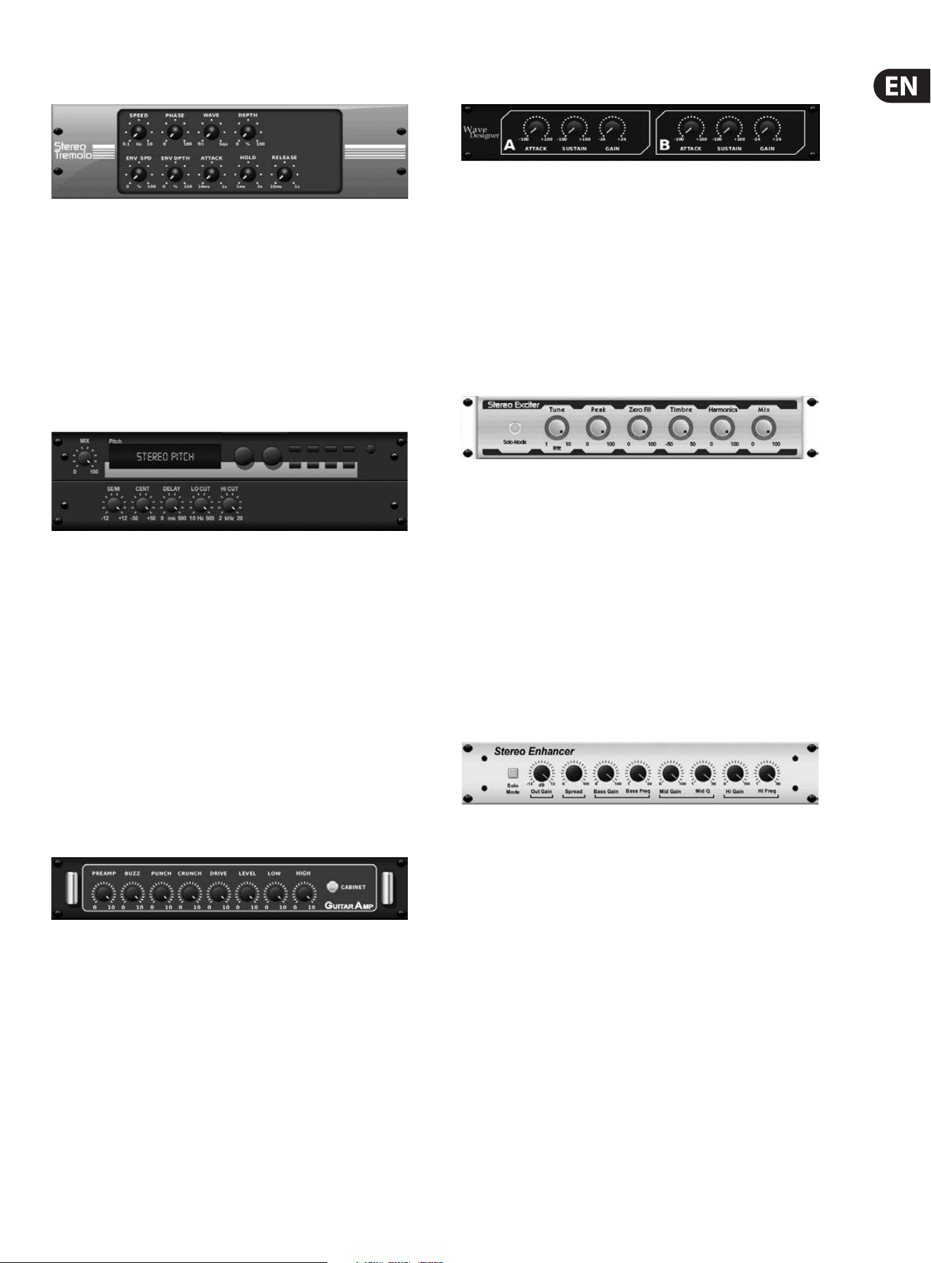
Tremolo / Panner
Stereo Tremolo creates an up and down volume change at a constant and even
tempo just like the guitar amps of yesteryear. Use X32’s Stereo Tremolo to add a
unique “surf-music” texture to a vocal or instrument track.
SPEED adjusts the LFO rate and DEPTH sets the amount of modulation.
PHASEcanbe used to set an LFO phase dierence between the left and right
channel, which can be used for panning eects. The WAVE knob blends the LFO
waveform between triangular and square shape. The signal envelope, shaped by
ATTACK, HOLD and RELEASE, can be used to modulate the LFO speed (ENV SPEED)
and the LFO modulation depth (ENV DEPTH).
Stereo / Dual Pitch
Pitch shifting is often used in two dierent ways. One is to set the Mix knob lower
and only use the Cent knob to make a small oset in pitch between the wet and
dry tones. This results in a “voice doubling” eect that thickens the overall sound
in a more subtle way. The extreme use of the eect is to turn the Mix knob fully-
clockwise so the entire signal is eected. This way, the signal can be shifted into
other keys up to an octave above or below the original. When used on a voice,
this results in a “chipmunk” sound or a low Darth Vader eect.
When the SEMI and CENT knobs are set at 12:00, the pitch is not altered.
Makingadjustments by semitone will have a very pronounced eect,
whereaschanges to the CENT knob will be very minor. The DELAY knob creates a
time dierence between the wet and dry sound. The LO and HI CUT knobs allow
the eected signal to be band-limited. The Dual Pitch eect allows the left and
right channels to be adjusted independently, and allows GAIN compensation and
panning of the two channels.
Stereo / Dual Guitar Amp
Modeled after the Tech 21 SansAmp, the Stereo / Dual Guitar Amp simulates the
sound of plugging into a real guitar amp. From shimmering cleans to saturated
crunch, X32’s Stereo / Dual Guitar Amp allows an electric guitar player to sound
great without using an amp on stage.
The PREAMP knob adjusts the amount of input gain prior to the band-specic
distortion adjustment. BUZZ adjusts the low-end breakup, PUNCH adjusts
the midrange distortion, and CRUNCH tailors the high-frequency content and
distortion for smooth or cutting notes. The DRIVE knob simulates the amount
of power amp distortion from a tube amp. The LOW and HIGH knobs allow
EQ adjustment independent of distortion content, and the overall output is
controlled by the LEVEL knob. The CABINET simulation can be bypassed if the
guitarist is already using a real cab, which allows the eect to function like a
boost or distortion pedal. The Dual Guitar Amp allows the left and right channels
to be adjusted independently.
Wave Designer
Wave Designer is a powerful tool for adjusting signal transients and dynamics,
such as attack and sustain. Use it to make a snare drum really “crack” in the
mix or level out volume inconsistencies of slap bass tracks. (Inspired by the SPL
Transient Designer)
Adjusting the ATTACK knob can add punch or tame overly dynamic signals.
Increasing the SUSTAIN knob acts in a similar way as a compressor, allowing the
peaks to carry longer before decay. The eect can also be used to reduce the
sustain for a more staccato sound. The GAIN knob compensates for level changes
caused by the eect.
Stereo Exciter / Dual Exciter
Exciters increase presence and intelligibility in live sound applications, and are
indispensable for adding clarity, air and harmonic overtones in the recording
studio. This eect is particularly useful for lling out the sound in dicult rooms
and for producing a more natural live/recorded sound. (Inspired by the famous
Aphex Aural Exciter)
Set the frequency of the side-chain lter with the TUNE knob, and further shape
the lter slope with the PEAK and ZERO FILL knobs. Turning the TIMBRE knob
left of center adds more odd harmonics, while turning it right of center adds
more even harmonics. Adjust the harmonic content added to the signal with
the HARMONICS knob, and blend in the eected signal with the MIX knob.
Engagethe SOLO MODE to isolate only the audio resulting from the eect so you
can hear exactly what you’re adding to the mix.
Stereo Enhancer / Dual Enhancer
X32’s Enhancers are so called “Psycho EQs”. They can enhance the signal
spectrum in bass, midrange and high frequencies but they dier from traditional
equalizers. When you need to generate maximum punch, clarity and detail,
without turning up the overall volume, our enhancers are the solution.
(Inspiredby the SPL Vitalizer)
Adjust the BASS, MID and HI GAIN knobs to add or reduce content in those
spectrums. The BASS and HI FREQuencies can be specically selected, while the
MID Q (bandwidth) can be adjusted instead. The OUT GAIN knob compensates for
changes in level resulting from the eect, and the SPREAD knob (Stereo version
only) emphasizes the stereo content for a wider mix. Engage the SOLO MODE
to isolate only the audio resulting from the eect so you can hear exactly what
you’re adding to the mix.
14 X32 CORE DIGITAL RACK MIXER User Manual
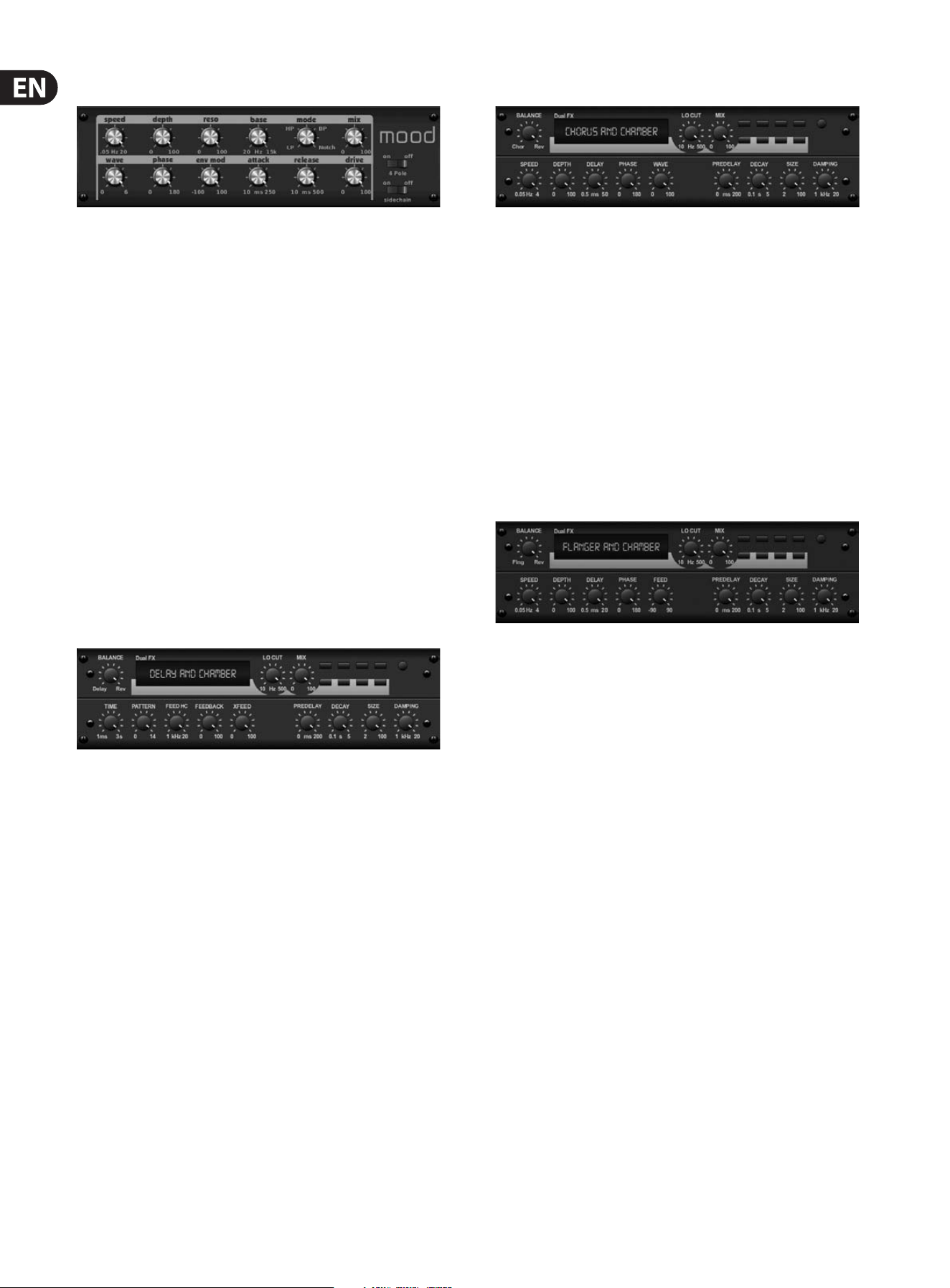
Mood Filter
The Mood Filter uses an LFO generator and an auto-envelope generator to control
a VCF (voltage-controlled lter), as well as a side chain function where the
channel B signal controls the envelope of channel A. When applied to electronic
instruments, the Mood Filter can be used to emulate the natural sound of
acoustic instruments. (Inspired by the MiniMoog)
This lter can be modulated with the signal’s envelope using the ENV MOD
(withpositive and negative amounts), ATTACK and RELEASE knobs, or the LFO
can modulate the lter. The WAVE knob selects between 7 dierent wave forms
– triangular, sine, saw plus, saw minus, ramp, square, and random. The PHASE
can be oset by up to 180 degrees. The SPEED knob adjusts the rate of the LFO
and the DEPTH adjusts the amount of LFO modulation. Adjust the resonance of
the lter until self-oscillation with the RESO(nance) knob. BASE adjusts the range
of the lter from 20 Hz to 15 kHz. The MODE switch selects between low pass
(LP), high-pass (HP), band-pass (BP) and Notch. Use the MIX knob to blend the
eected signal with the dry sound. With the 4 POLE switch engaged, therewill
be a steeper slope than the OFF (2 pole) setting. The DRIVE knob adjusts the
level and can also introduce an overdrive eect (as with real analogue lters)
ifpushed hard. In Sidechain mode, only the left input signal is processed and
fed to both outputs. The envelope of the right input signal can be used as a
modulationsource.
Delay + Chamber
Here we have combined Delay and Chamber reverb, so a single device can provide
a variety of delay settings, plus add just the right type and amount of reverb to
the selected signal. This device only uses one FX slot. (The Reverb is Inspired by
the Lexicon PCM 70)
Use the BALANCE knob to adjust the ratio between delay and reverb.
Lowfrequencies can be excluded with the LO CUT knob, and the MIX adjusts
how much of the eect is added to the signal. The TIME knob adjusts the delay
time for the left channel delay, and the PATTERN sets the delay ratio for the
right channel delay. Adjust the FEEDBACK and trim some high frequencies with
the FEED HC (high-cut) knob. The XFEED knob allows you to send the delay
sound to the reverb eect, so instead of running completely parallel, the reverb
eects the echos to a selected degree. The PREDELAY knob determines the
hesitation before the reverb aects the signal. The DECAY knob adjusts how
quickly the reverb fades. The SIZE controls how large or small the simulated
space is (room,cathedral, etc.). The DAMPING knob determines the decay of high
frequencies within the reverb tail.
Chorus + Chamber
Taking up only one FX slot, the Chorus + Chamber eect combines the shimmer
and doubling characteristics of a studio-grade Chorus with the sweet sound of a
traditional Chamber reverb. (Reverb is Inspired by the Lexicon PCM 70)
The BALANCE knob adjusts the balance between chorus and reverb.
Lowfrequencies can be excluded with the LO CUT knob, and the MIX knob adjusts
how much of the eect is added to the signal. SPEED, DELAY and DEPTH adjust
the rate, delay, and modulation depth of the chorus. The LFO PHASE between left
and right channel can be oset by up to 180 degrees, and WAVE adjusts the LFO
waveform from a sine wave to triangular wave. The PREDELAY knob determines
the hesitation before the reverb aects the signal. The DECAY knob adjusts how
quickly the reverb fades. The SIZE controls how large or small the simulated
space is (room, cathedral, etc.). The DAMPING knob determines the decay of high
frequencies within the reverb tail.
Flanger + Chamber
Add the mind-bending, lter-sweeping eect of a state-of-the-art Flanger to
the elegant sweetening of a traditional Chamber reverb—all in one FX slot.
(Reverbis Inspired by the Lexicon PCM 70)
The BALANCE knob adjusts the ratio between anger and reverb. Low frequencies
can be excluded with the LO CUT knob, and the MIX knob adjusts how much of
the eect is added to the signal. SPEED, DELAY and DEPTH adjust the rate, delay,
and modulation depth of the anger. FEEDback can be adjusted with positive and
negative amounts. The PHASE can be oset by up to 180 degrees. The PREDELAY
knob determines the hesitation before the reverb aects the signal. The DECAY
knob adjusts how quickly the reverb fades. The SIZE controls how large or small
the simulated space is (room, cathedral, etc.). The DAMPING knob determines the
decay of high frequencies within the reverb tail.
15 X32 CORE DIGITAL RACK MIXER User Manual
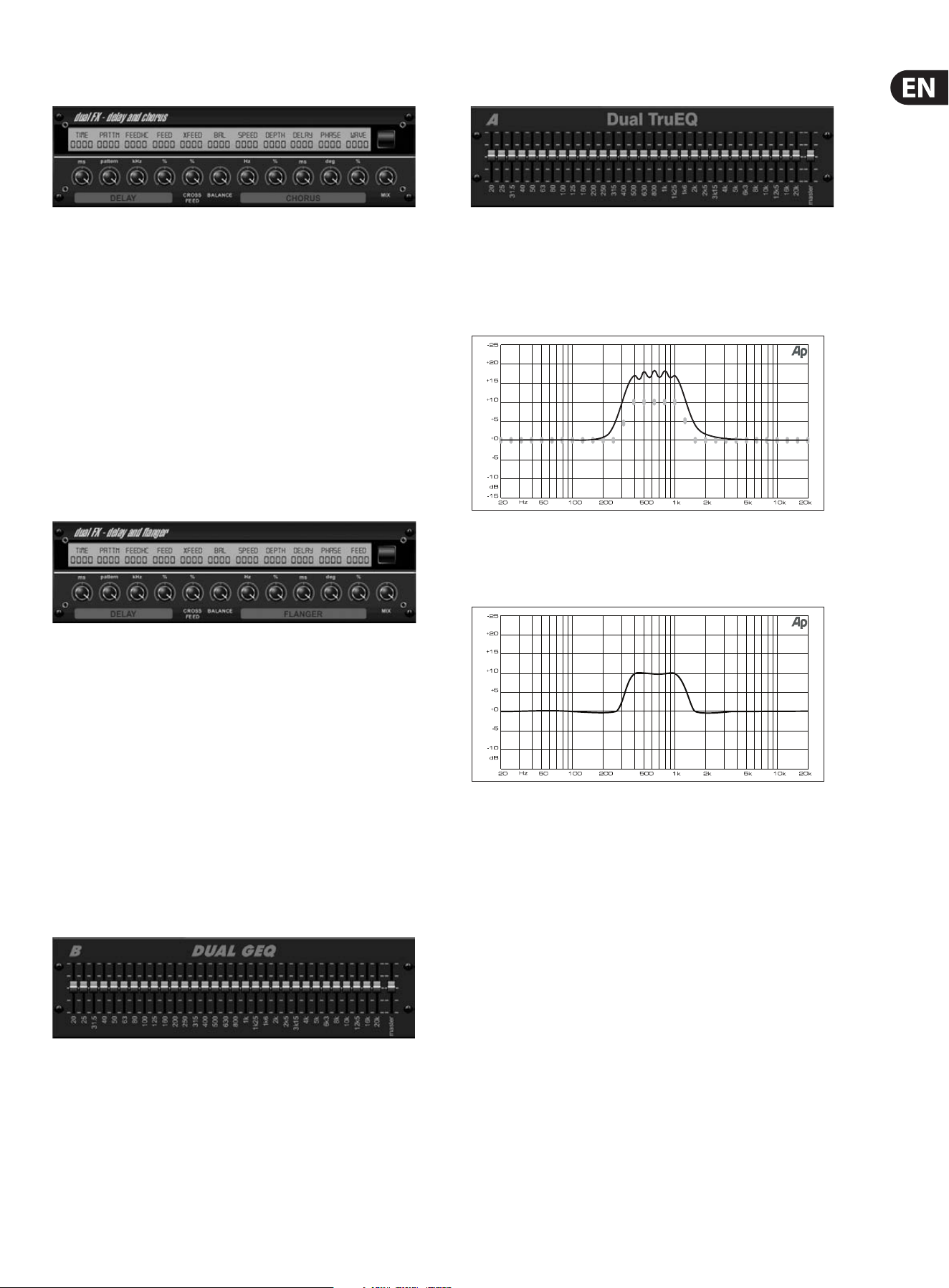
Delay + Chorus
This combination eect merges a user-denable Delay (echo) with a studio-
quality Chorus sure to fatten up even the “skinniest” track. Uses only one FX slot.
(Inspired by the TC Electronic D-Two)
The TIME knob adjusts the delay time, and the PATTERN knob sets the delay ratio
for the right channel and negative values activate a cross feedback between
the two channels. The FEEDHC knob adjusts the delay high-cut frequency,
whilethe FEEDBACK knob adjusts the number of repeats. The X-FEED knob allows
you to send the delay sound to the chorus eect. The BALANCE knob adjusts
the ratio between delay and chorus. SPEED, DELAY and DEPTH adjust the rate,
delay,andmodulation depth of the chorus. The right channel LFO PHASE can be
oset by up to 180 degrees, and WAVE adjusts the chorus character by shaping
the LFO waveform from sine wave to triangular wave. Use the MIX knob to blend
the eected signal with the “dry” sound.
Delay + Flanger
This handy dynamic duo blends the “woosh” of soaring jet planes with classic
Delay, and can be adjusted from mild to wild. This combination eect only takes
up one FX slot. (Inspired by the TC Electronic D-Two)
The TIME knob adjusts the delay time, and the PATTERN knob sets the delay ratio
for the right channel and negative values activate a cross feedback between
the two channels. The FEEDHC knob adjusts the delay high-cut frequency,
whilethe FEEDBACK knob adjusts the number of repeats. The X-FEED knob
allows you to send the delay sound to the anger eect. The BALANCE knob
adjusts the ratio between delay and anger. SPEED, DELAY and DEPTH adjust the
rate, delay, andmodulation depth of the anger. The right channel LFO PHASE
can be oset by up to 180 degrees, and FEED (positive and negative amounts)
adjuststhe feedback eect. Use the MIX knob to blend the eected signal with
the “dry”sound.
Dual / Stereo GEQ
These are standard graphic equalizers that provide 31 bands of adjustment
between 20 Hz and 20 kHz. A master volume slider compensates for changes in
volume caused by the equalization. A maximum boost or cut of 15 dB is available
for each band.
Dual / Stereo TruEQ
The TruEQ incorporates a special algorithm that compensates for the gain
adjustment overlapping eect that adjacent frequency bands have on one
another. On a standard EQ, when neighboring bands are boosted together,
theresulting eect is magnied beyond what is visible from the positioning of
thesliders.
Graphic equalizer without frequency response correction.
This compensated EQ will produce an adjustment that is identical to the actual
positioning of the sliders.
Graphic equalizer with frequency response correction.
Dual / Stereo DeEsser
Rotate the 1st and 2nd encoder to adjust the low and high-band reduction
respectively. Press the 1st encoder to select male or female to optimize the
frequency for the vocalists range. Repeat the steps for the B channel using the
3rd and 4th encoders. If using the Stereo DeEsser, press the 5th encoder to select
between Stereo or Mono/Stereo, which allows the left and right channels to be
adjusted independently.

16 X32 CORE DIGITAL RACK MIXER User Manual
5. Topic Guide
5.1 Firmware updates
The X32 CORE rmware can easily be updated by performing the following steps:
• Download the new console rmware from the X32 CORE product page onto
the root level of a USB thumb drive
• Plug the USB thumb drive into the front panel USB connector while the
console is turned o
• Hold the SCENE/SETUP button depressed while switching the console on.
While booting, the X32 CORE will run a fully automatic rmware update,
which will take 2-3 minutes longer than the regular boot sequence
When no update le is available on the USB drive, or when it is corrupted,
theupdate mode will remain active, preventing the X32 from booting regularly.
Switch the console o and back on without holding the SCENE/SETUP button to
boot the console with the existing rmware.
5.2 Remote control
The X32 CORE hosts an Ethernet port on its rear panel which can be used to
connect and remote control it over a network via the X32-Mix on an iPad or the
X32-Edit application on a PC. To be able to do this the X32 CORE has to be set
up properly.
• Enter Setup Mode by pressing and holding the SCENE/SETUP button
until the LED turns green.
• Rotate the Select knob to select “6. IP Address.” Press the Select knob
toconrm.
• Set an IP address which ts your network, normally 192.168.0.X.
Rotatethe Select knob to adjust the 1st triplet (0-255), then press to
conrm. Repeat this to enter the 2nd, 3rd and 4th triplet in the address.
The nal press will exit.
• Set your subnet mask according to your network, normally
255.255.255.0. Select setup page “7. IP Mask” and follow the same
procedure as the IP address.
• Set your gateway, if required, by selecting Setup page “8. IP Gateway”
and following the same procedure described above.
Now get your iPad or remote PC into the same network and open the X32-Edit.
PC:
• On the X32-Edit, choose setup on the right side and the network tab.
Enter the IP address of the X32 in the network and press connect.
• If the software has connected to the X32 you can also synchronize them
in 2 directions. Console -> PC means all settings in the X32 will be
loaded into the X32-Edit. PC -> Console means that all settings in the
X32-Edit will be written to the console.
X32-Mix
• For the X32-Mix remote, open the program on your iPad (make sure the
iPad is connected to the same network as the console).
• On the startup screen, a popup should appear. Enter the IP of the
console, press “Go Online”, et voilà: you are connected and can control
the X32 CORE with your iPad.
5.3 Recording a 2-track directly with
theconsole
The X32 CORE oers the possibility to record a 2-track of your mix (or any other
selection of signals) directly onto a USB-stick/external USB hard disk:
• Plug a FAT-formatted (FAT12, FAT16, FAT32) USB stick into the USB port
on the front panel.
• In your X32-Mix or X32-Edit software, navigate to the Recorder screen.
• On the cong tab you can select the source for the recording, default is
main L and R.
• Press RECORD (encoder #5) to record your mix.
• To adjust the volume during playback, use the virtual faders for Aux 7
and 8, which are assigned to USB playback by default.
Remarks:
Due to the FAT format of the stick, the le size will be limited to 2 GB, which is
about 3 hours of stereo recording. Please test the recording capability of your USB
device before you do the “real stu” as some sticks may not be supported or be
too slow. We also recommend you defragment your USB device prior to recording.
The recording will be done as 16-bit WAV le with the selected sample frequency
of the console.
Please also note that it is possible that the specications of USB storage devices
may be changed by the manufacturer without any change in physical appearance
or notication.
5.4 Saving and recalling scenes
Follow the steps below to save and recall scenes in the console, allowing dierent
congurations to be recalled at a later time.
• Adjust all settings of the console so that all elements of the mix are
asdesired.
• Select the Scenes menu in your remote software. The display will show
various controls for saving and recalling console scenes.
• Press the rotary control labeled “Save Settings” to save the console’s
current conguration to the next available empty scene and label it with a
customname.
• Adjust the console to the next desired conguration, and repeat the process
above as needed, saving additional scenes to additional empty slots.
• To recall a scene, scroll through the list of saved scenes. A gray box will
indicate which item is currently selected. When the desired scene is selected,
press the "GO" button and the console will switch to that scene. All console
parameters will switch to the state they were in when saved to the scene
that was just recalled.

17 X32 CORE DIGITAL RACK MIXER User Manual
5.5 How do I add one of the 8 internal eects
to the sound?
There are two types of eects that are commonly used:
• “Eects Loop” (side chain) style eects, where multiple channels all send
varying amounts of their signal to a common eect, such as a reverb,
delay,or chorus.
• “Insert” style eects that are inserted in to the signal path of a single
channel of audio. Examples would be a graphic EQ, lter, exciter,
ortubeemulator.
To apply an “Eects Loop” style eect:
• Select the “Eects” menu in either the X32-Mix or X-32 Edit software.
Themain screen will show the FX home screen where dierent eects
processors are assigned to the 8 processing slots.
• Adjust rotary encoder #6 to highlight the rst eects processor; it will be
surrounded by an orange outline. You may also click or tap directly on the
desired processor to select.
• Select your desired bus as the source for both the left and right inputs of the
rst eect processor.
• Select a specic eect processor, suchas “Ambience”.
• Adjust FX1L and FX1R up to 0 dB.
• With the desired eect highlighted, select the 'Edit' button beneath the 6th
encoder to adjust the eect parameters.
• Press the Home button again and tab over to the ‘sends’ page. Raisethe
virtual faders for the channels to which you want to add the eect.
The higher you raise the fader, the more of that channel's signal will be sent
to the processor.
To apply an “insert” style eect:
• Select the “Eects” menu in either the X32-Mix or X-32 Edit software.
• As the eects on the left side are also able to handle complex send eects
like reverb, the slots on the right side shall be used for insert eects like
limiter, graphic EQ, etc. You can also use insert eects on the left side,
butthis will limit your use of reverbs and other processor-intensive eects.
• Select one of the eects processors on the right side; it will be surrounded by
an orange outline.
• Select a channel or bus to assign to the processor, then select “Ins” to assign
as an insert eect.
• Select a specic eect processor, such as “precision limiter”.
• Navigate to the Home -> Cong screen.
• Select the specic processor you have applied the eect to, in this case
“InsFX 5L”. Press the encoder to connect the selected insert eect.
• The Precision Limiter is now applied as an insert on the selected channel.
Sending more than one channel through the same insert eect is, of course,
prohibited. There will be a warning when you try to insert an eect slot that
has already been used as an insert on any other channel. Both sides of a dual
type eect can be used as inserts on dierent channels or buses.
18 X32 CORE DIGITAL RACK MIXER User Manual
6. USB Interface Operation Guide
Host system requirements for X-USB interface
expansion card
Check the BEHRINGER website at behringer.com for updates of X-USB rmware
or system requirements. Please nd the recommended hardware/software
minimum congurations in the specications section.
The BEHRINGER X-USB High-Performance 32-Channel
24-Bit USB Audio Interface
The X-USB card provides 32 channel, bi-directional audio I/O via USB 2.0 to
Mac or Windows PC. The simultaneous 32-in, 32-out audio channels enable
extremely powerful studio and live applications. You can run virtual live sound
checks or 32-track high-quality studio recordings, whileat the same time
remote operating your DAW via HUI/MackieControl emulation. Thehigh speed
24-bit signal transmission and ultra-low latency ASIO drivers and CoreAudio
compatibility even allow inserting audio plugins on your PC to perform advanced
outboard processing.
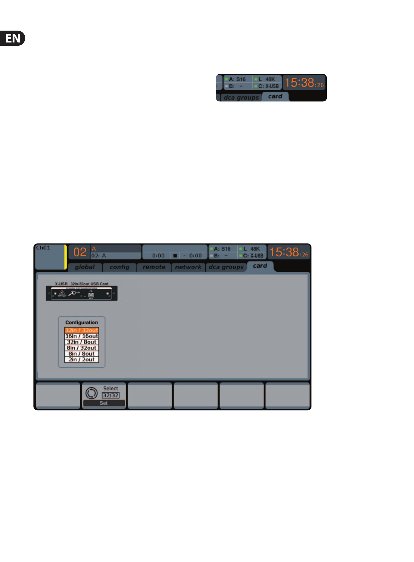
6.1 Conguring the X-USB card for use in
theconsole
The console will automatically detect the X-USB card during the regular boot
cycle, and it will display the card’s presence in several instances.
The green square in front of “C: X-USB” indicates that the card is installed and
working properly.
Conguration
After the console has fully booted up, you can access the Setup/Card screen in
your remote software to view the current channel count conguration.
Depending on your application, you may want to select an option other than the
maximum 32 x 32 channel count to preserve system resources.
19 X32 CORE DIGITAL RACK MIXER User Manual
This mode obviously allows the full potential of the interface to be tapped.
Notethat the computer needs to be able to handle that amount of concurrent I/O
stream without any glitches. Depending on its speed and memory conguration,
someoptimization for audio recording might be required.
It is also possible to run a virtual sound check of all 32 input channels by recording
them directly to a computer during a brief line check. The performers can leave
the stage while you play back the recorded instruments from the hard drive and
tweak the sound accordingly.
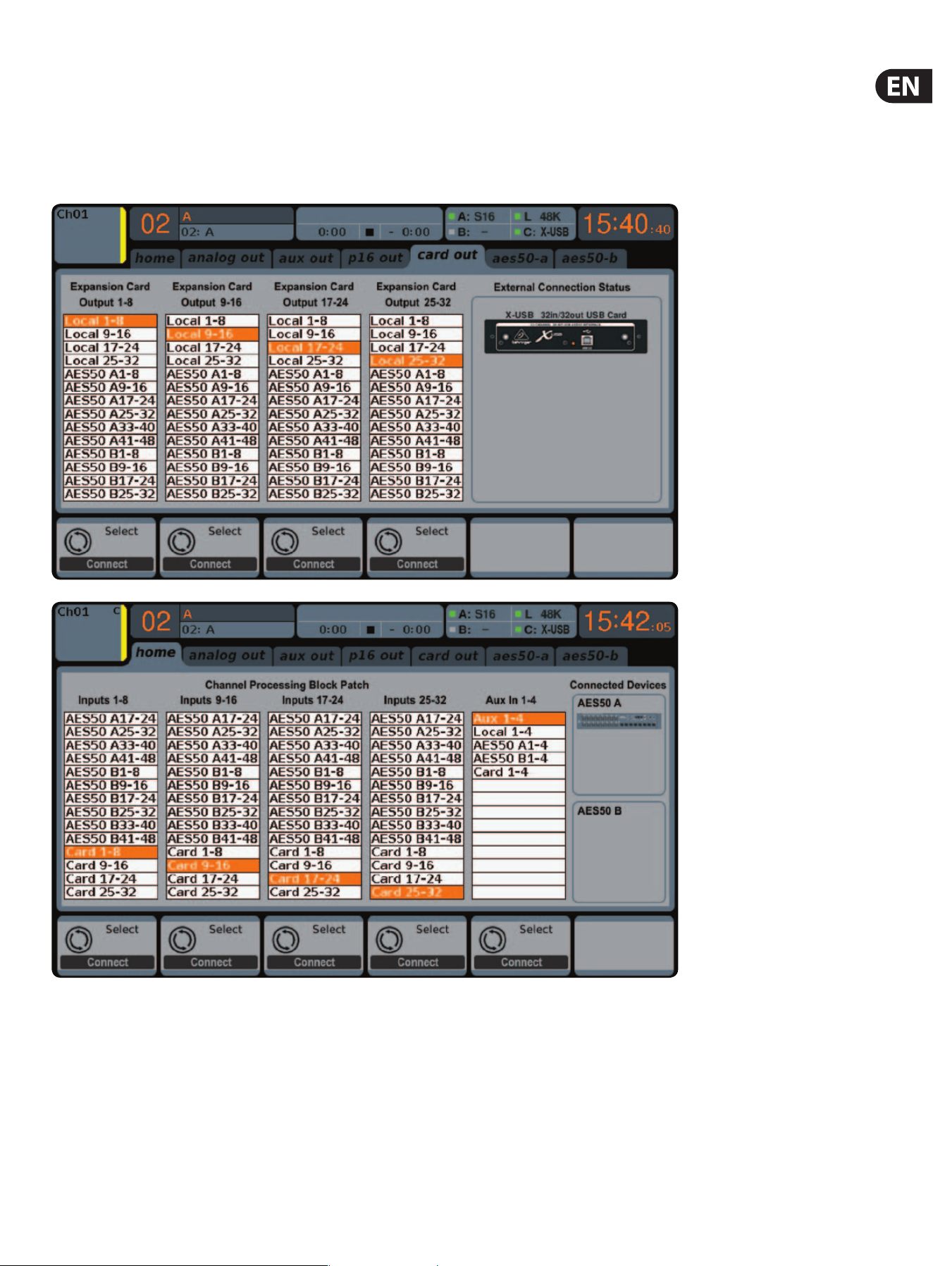
32 in / 32 out
Generally, the Card outputs may use any of the available signal sources in the
console (local or AES50) for recording independently. When the X32 CORE is used
in a quasi in-line mode, the card with connected computer represents a classic
tape machine. In this case, the connected S16 mic inputs would be selected
to feed the card outputs (see graphic), and all signals are run from the S16’s
preamps directly to the multi-track recording machine (PC) and from there 1:1
back into the console’s input channels.
When the console channel inputs are set to Card, the channel Gain control will be a
+/- 12 dB digital trim for the interface card signal, without direct access to any head
amp - which is great for mixdown but would be an issue for recording. So, mixing and
monitoring can be done using the X32 CORE input channel controls, but the actual
mic preamps must now be controlled from the Setup/preamps page, which gives
remote control to every one of the available preamps in the system. Use the Setup/
preamps page to make sure that phantom power is set as needed, and that there is a
reasonable amount of headroom for recording the preamp signals.
TIP: Sometimes it is more convenient to run the sound check while the preamps
are still connected to the X32 CORE input channels. Once you are condent about
the fundamental settings, you can switch the channel inputs to the X-USB Card
inputs for laying the tracks and monitoring the DAW outputs.
If you wish to switch back and forth between the two modes more frequently,
you could consider storing 2 routing scenes, ’DAW’ and ’preamps’. Make sure
Scene Safes are set in a way that all other parameters remain unchanged.
20 X32 CORE DIGITAL RACK MIXER User Manual
32 in / 8 out
This mode is tailored to suit a typical studio and overdub recording situation,
withmany input channels but only a few output channels for monitoring of
previously recorded takes.
8 in / 8 out and 2 in / 2 out
For very small recording sessions or overdubs with single sources like vocals,
reducing the channel I/O frees up more processing power and ensures stable
operation with small latency settings.
8 in / 32 out
This is a useful mode for utilizing the excellent audio engine and eects
processing of the console during nal mixdown of your project. All 32 tracks
would be fed from your DAW into the console where all the magic happens.
Thenonly 2-8 tracks of the complete mixdown would be sent back to the DAW.
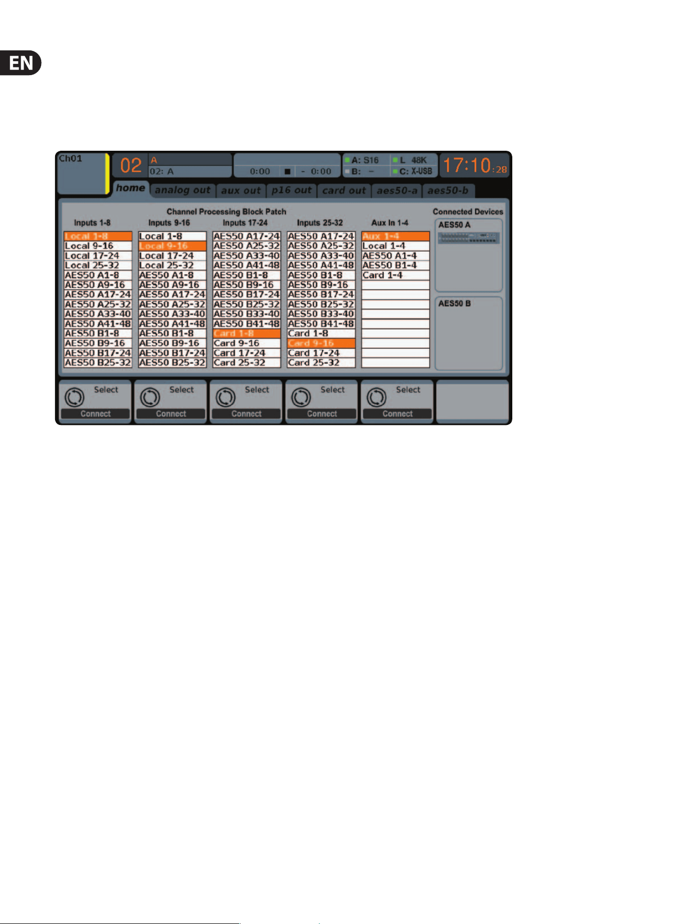
16 in / 16 out
If you don’t actually need more than 16 concurrent input and output tracks to
be exchanged between the console and your PC, then this mode might be more
appropriate for you. First, it will slow the required bandwidth on the interface
down. Second, there will be no excessive I/O tracks in your DAW conguration
that might clutter your setup. Third, it allows you to run a fully-featured
zero-latency overdub setup, which would be impossible if signals were run
through the computer. In this case, the 16 input signals are put on channels
1-16, whilethe tape (card) returns are put on channels 17-32. The monitoring is
directly fed from Ch1-16 as usual, including all processing and eects. It remains
independent from any computer audio latency, even though you can hear back all
the recorded tracks without any repatching.
21 X32 CORE DIGITAL RACK MIXER User Manual
6.2 Conguring the PC to Interface
withtheX-USB Card
Please watch behringer.com for further advice on the software conguration of
X-USB interface card.
Windows: There is an ASIO high-performance driver available for
download, which is essential for low-latency audio on
Windows computers.
MacOS: The X-USB is CoreAudio compatible and thus works with
low-latency on Mac computers without any additional
driverinstallation.
Windows ASIO Driver
Download the X32 ASIO driver installer les from behringer.com. Double-click on
Setup.exe in the corresponding unpacked folder and follow the instructions on
the screen.
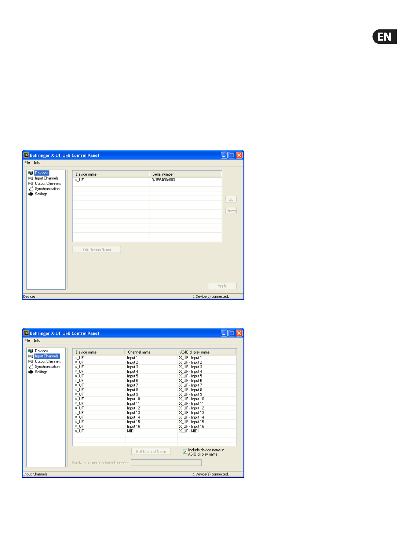
Driver Control Panels
Once the driver is installed, you can open the control panel by double-clicking
on the small tray icon. These screens will allow conguring the X-USB expansion
card in the X32 CORE as an audio interface for your computer.
The ’Devices’ screen displays the card name and serial number. You can rename
the card if necessary.
The ’Input Channels’ screen allows you to name each input channel for more
organized mixing.
22 X32 CORE DIGITAL RACK MIXER User Manual
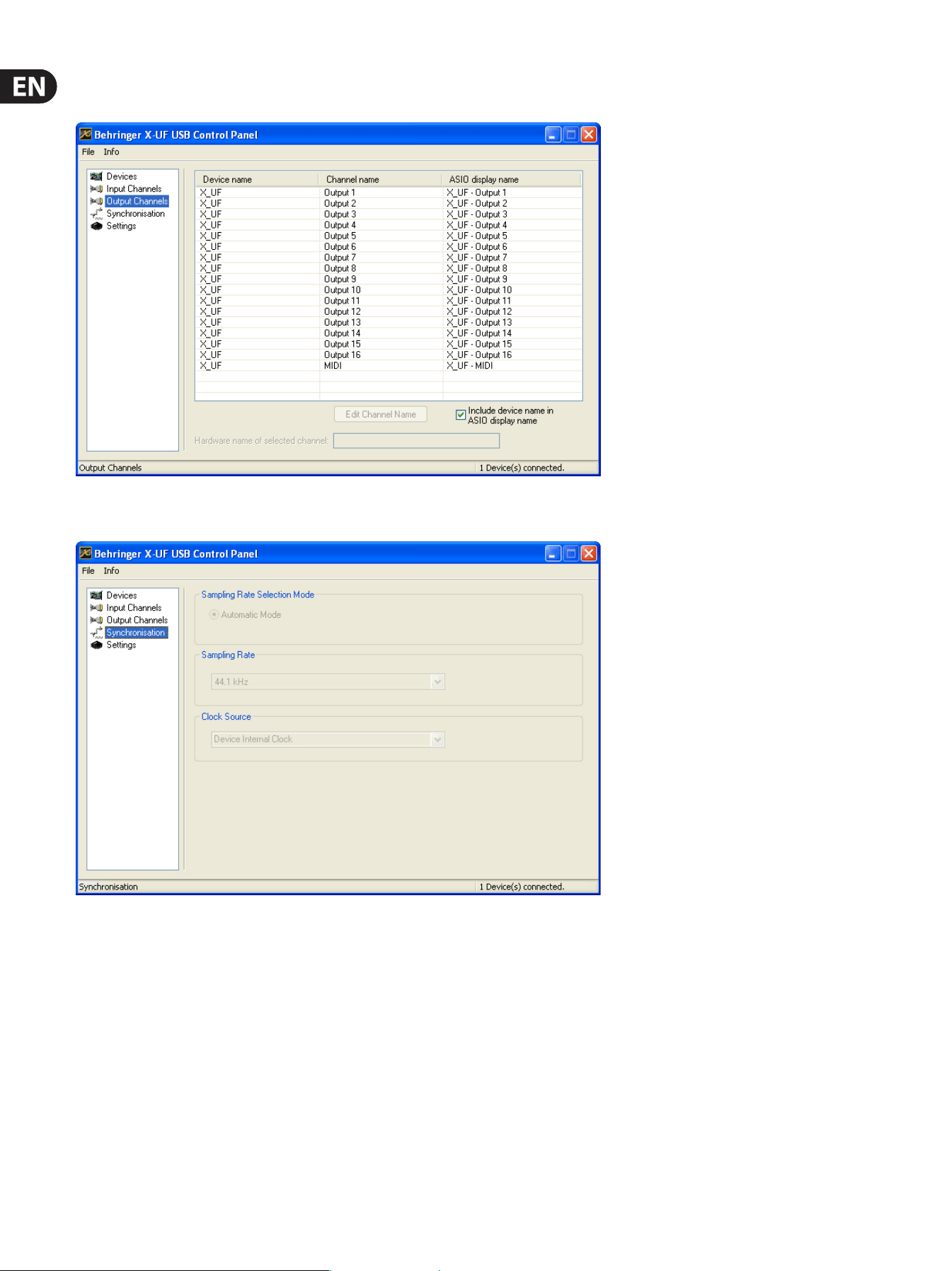
The ’Output Channels’ screen allows you to name each output channel for more
organized mixing.
The ’Synchronisation’ screen allows manual selection of the sample rate and
clocksource.
23 X32 CORE DIGITAL RACK MIXER User Manual
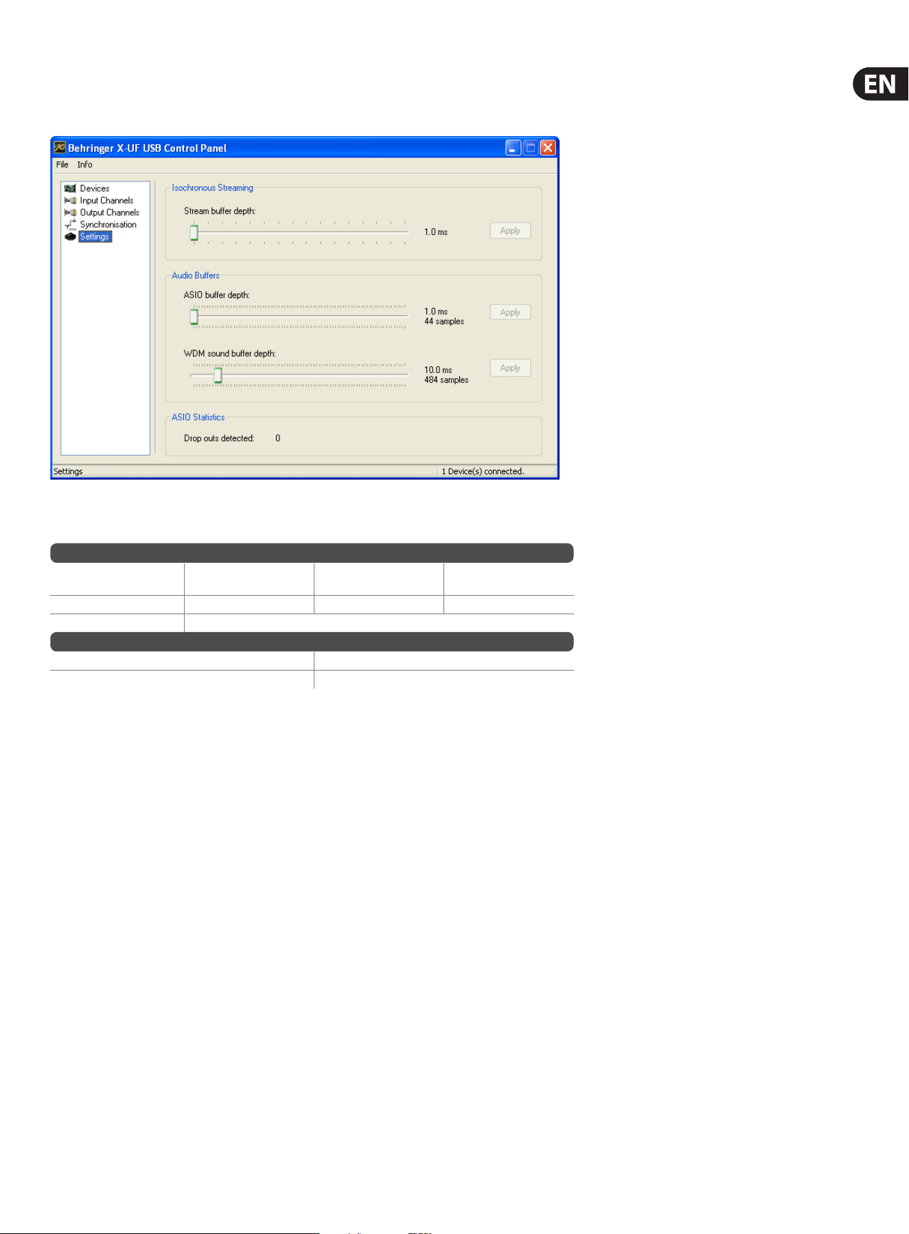
The ’Settings’ screen allows the stream, ASIO, and WDM sound buers to be set.
Any detected drop outs will be documented as well, in which case a larger buer
should be selected.
6.3 X-USB Specications
* depends on system performance and application
Expansion Card Features:
Interface MIDI
Audio input channels
24-Bit, 44.1/48 kHz
Audio output channels
24-Bit, 44.1/48 kHz
HighSpeed USB 2.0 1 in x 1 out 32, 16, 8 or 2 32, 16, 8 or 2
DAW remote control Generic, HUI and Mackie Control emulation
Expansion Card Performance:
Interface Typical round-trip latency
HighSpeed USB 2.0 ~14 ms
Recommended Minimum Hardware:
Windows PC - Core 2 Duo CPU, 2 GHz
- USB 2.0 port
- 1 GB RAM
Mac - 1.5 GHz CPU
- USB 2.0 port
- 512 MB RAM
Recommended Operating Systems:
Windows: XP 32-Bit SP2 or higher, Win7 32-bit, Win7 64-bit, Win8 64-bit
(X-USBASIO drivers supplied)
MacOSX: 10.5 Leopard, 10.6 Snow Leopard, 10.7 Lion, 10.8 Mountain Lion
(CoreAudio compatible)

24 X32 CORE DIGITAL RACK MIXER User Manual
7. Specications
Processing
Number of processing channels
32 input channels, 8 aux channels, 8 FX return channels,
16 aux buses, 6 matrices, main LRC
Internal eects engines, true stereo / mono 8 / 16
Internal total recall scenes (incl. preamp and
fader)
100
Signal processing 40-bit oating point
Network I/O latency (stagebox in > console
processing* > stagebox out)
1.1 ms
Connectors
Talkback mic input, TRS 1 external (no phantom power)
Monitoring outputs ¼" TRS balanced 2
Phones outputs, ¼" TRS 1 stereo (front)
AES50 ports, SuperMAC 2
Expansion card slot 32 channel audio input/output, various standards
P-16 connector, Ultranet (no power supplied) 1
MIDI inputs / outputs 1/1
Ethernet, RJ45, rear panel, for remote control 1
USB Type A, front panel, for audio and data
export/import
1
Indicators
LCD screen 128 x 64, LCD with RGB color backlight
Main meter
AES50 Port A/B status, Signal, 7-segment level
(-30 dB to clip)
Power
Switch-mode power supply Autorange 100-240 V (50/60 Hz)
Power consumption 40 W
Physical
Standard operating temperature range 5°C – 40°C (41°F – 104°F)
Dimensions 483 x 307 x 43.8 mm (19 x 12 x 1.7")
Weight 3.6 kg (7.9 lbs)
*including all channel and bus processing, excluding insert effects and line delays
iPhone, iPad, and OS X are trademarks of Apple Inc., registered in the US and other countries. Windows is a registered trademark of Microsoft Corporation in the United States and other countries.
Linux is a registered trademark of Linus Torvalds.
25 X32 CORE DIGITAL RACK MIXER User Manual
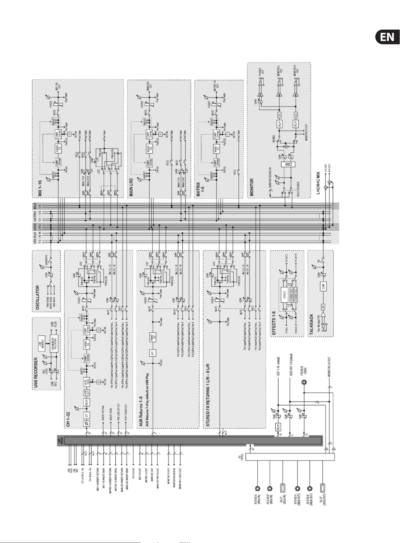
Block Diagram

26 X32 CORE DIGITAL RACK MIXER User Manual
X32 MIDI Implementation
MIDI RX > SCENES
Whenever program change messages in the range 1-100 are received on MIDI
CH01, the corresponding scene of the X32 internal show memory will be loaded.
This requires the following preconditions:
• Setup / remote
> MIDI In/Out check marks must be set according to the connection on
which MIDI input will be accepted (via physical MIDI connectors on X32 or
S16, or via XUF Card)
> MIDI In/Out check mark must be set for “Enable MIDI Scene Recall”
• Setup / global
> when tick mark “Conrm Pop-Ups” / “Scene Load” is active, also MIDI
scene recalls will only become active after manual conrmation
> if you prefer activating scenes via MIDI program changes immediately,
un-check the “Conrm Pop-Ups” / “Scene Load” tick mark
• Scenes View / home
> valid scenes must be stored in the internal X32 show le. It is not possible
to recall empty scenes.
> the scope of changes applied by a MIDI scene recall depends on the Scene
Safes, Parameter Safes and Channel Safes settings, same as with recalling
the scene locally.
MIDI TX > SCENES
Every scene can be assigned one specic MIDI command/event. Each time the
scene is loaded the MIDI command will be sent out once. Possible choices for MIDI
commands/events to be found on Scenes View/MIDI page:
• O > no message will be sent upon scene load
• Program Change > select the MIDI Channel and the Program Number
(using knobs 4/5 at the main display)
• Control Change > select the MIDI Channel, Controller number and value
(using knobs 4-6 at the main display)
• Note > select the MIDI Channel, Note number and velocity (using knobs 4-6
at the main display) > will send out a Note On command directly followed by
the same Note O command
MIDI RX > ASSIGN
Whenever assignable controls are set up for transmitting MIDI commands,
reception of that same command (status or continuous) will be reected on the
respective assignable control element (button light, encoder LED collar).
MIDI TX > ASSIGN
We restricted the user assignable MIDI commands to some generic elements,
in order to keep things simple enough:
• Encoders 1-4 > can be assigned to sending control changes, program
changes or notes
> parameters are currently ‘Channel’ and ‘Value’
> for CC and Note commands ‘Value’ = controller number/note number,
and the encoder rotation determines the controller value/note-on velocity
> for Program Changes only the channel is specied, and the encoder
rotation determines the program number
• Buttons 5-12 > can be operated in two modes, ‘MIDI Push’ (non-latching)
for momentary commands, or ‘MIDI Toggle’ (latching) for static commands
MIDI Push:
> can be assigned to sending control changes, program changes or notes
> parameters are currently ‘Channel’ and ‘Value’
> for CC and Note commands ‘Value’ 0…127 = controller number/note
number, and the button momentarily toggles the controller value/note-on
velocity to 127 (depressed)à0 (released]
> for Program Changes ‘Value’ 0…127 = program/preset number, that will
be sent upon pressing the button
MIDI Toggle:
> can be assigned to sending control changes or notes
> parameters are currently ‘Channel’ and ‘Value’
> for CC and Note commands ‘Value’ 0…127 = controller number/note
number, and the button toggles the controller value/note-on velocity
between value/velocity 127 and 0 with every operation
• n.b.1) The ASSIGN section also reects/displays reception of the same MIDI
commands that are selected for transmission
• n.b.2) The MIDI commands assigned to the ASSIGN controls can be
transferred to and from stage via AES50 using the S16 stage box MIDI I/O

27 X32 CORE DIGITAL RACK MIXER User Manual
MIDI RX/TX > REMOTE
Enables a specic form of bi-directional MIDI communication for remote
controlling a computer DAW application using control elements of the X32
console. REMOTE can be used in 3 modes, Mackie Control, HUI and raw MIDI CC
(raw) controllers (see Setup/remote)
• MIDI CC (raw) selected and Remote is enabled+active, the group
section buttons
> will emit the following messages on Channel 01:
Group 1-8 SELECT = Note 64-71, on(127)/o(0), push non-latching
Group 1-8 SOLO = CC 32-39, on(127)/o(0), toggle latching
Group 1-8 MUTE = CC 40-47, on(127)/o(0), toggle latching
Sends On Fader = CC 48, on(127)/o(0), toggle latching
Group DCA 1-8 = Note 72, on(127)/o(0), push non-latching
BUS 1-8 = Note 73, on(127)/o(0), push non-latching
BUS 9-16 = Note 74, on(127)/o(0), push non-latching
MTX 1-6 = Note 75, on(127)/o(0), push non-latching
MIDI CC (raw) selected and Remote is enabled+active, then group section
faders 1-8
> will emit CC #0-7, value 0…127 messages on Channel 01
• HUI selected and Remote is enabled+active, then the group fader section
and buttons will emulate the HUI control surface protocol, i.e. for ProTools.
> SELECT/SOLO 1-8 buttons will select or solo the corresponding track in the
DAW, in banks of 8 tracks
> Sends On Fader = enables touch-writing a fader automation on selected
track, track automation mode in DAW must be ‘touch’, (latching)
> use the layer buttons to determine the function assigned to the MUTE 1-8
buttons, the LED displays indicate that function
- Group DCA 1-8 = allows to move the bank selection of tracks in a DAW,
(push non-latching)
- BUS 1-8 = allows to set DAW tracks to ‘Record Ready’, (push non-latching)
- BUS 9-16 = enables using the MUTE buttons for track mute in the DAW,
(latching)
- MTX 1-6 = enables using the MUTE buttons for transport controls in the
DAW, (latching)
• MACKIE CTRL selected and Remote is enabled+active, then the group fader
section and buttons will emulate the Mackie Control Universal protocol
> SELECT/SOLO 1-8 buttons will select or solo the corresponding track in the
DAW, in banks of 8 tracks
> Sends On Fader = enables touch-writing a fader automation on selected
track, track automation mode in DAW must be ‘touch’ or ‘latch’, (latching)
> use the layer buttons to determine the function assigned to the MUTE 1-8
buttons, the LED displays indicate that function
- Group DCA 1-8 = allows to move the bank selection of tracks in a DAW,
(push non-latching)
- BUS 1-8 = allows to set DAW tracks to ‘Record Ready’, (push non-latching)
- BUS 9-16 = enables using the MUTE buttons for track mute in the
DAW, (latching)
- MTX 1-6 = enables using the MUTE buttons for transport controls in the
DAW, (latching)

28 X32 CORE DIGITAL RACK MIXER User Manual
FEDERAL COMMUNICATIONS
COMMISSION COMPLIANCE
INFORMATION
Responsible Party Name: MUSIC Group Services NV Inc.
Address: 5270 Procyon Street
Las Vegas, NV 89118
USA
Phone Number: +1 702 800 8290
X32 CORE DIGITAL RACK MIXER
complies with the FCC rules as mentioned in the followingparagraph:
This equipment has been tested and found to comply with the limits for a ClassB
digital device, pursuant to part 15 of the FCC Rules. These limits are designed
to provide reasonable protection against harmful interference in a residential
installation. This equipment generates, uses and can radiate radio frequency
energy and, if not installed and used in accordance with the instructions, may cause
harmful interference to radio communications. However, there is no guarantee that
interference will not occur in a particular installation. If this equipment does cause
harmful interference to radio or television reception, which can be determined
by turning the equipment o and on, the user is encouraged to try to correct the
interference by one or more of the followingmeasures:
• Reorient or relocate the receiving antenna.
• Increase the separation between the equipment and receiver.
• Connect the equipment into an outlet on a circuit dierent from that to which the
receiver is connected.
• Consult the dealer or an experienced radio/TV technician forhelp.
This device complies with Part 15 of the FCC rules. Operation is subject to the
following two conditions:
(1) this device may not cause harmful interference, and
(2) this device must accept any interference received, including interference that may
cause undesired operation.
Important information:
Changes or modications to the equipment not expressly approved by MUSIC Group
can void the user’s authority to use the equipment.
X32 CORE DIGITAL RACK MIXER

We Hear You