
Sharp Corporation
Digital Full Color
Production Printer
BP-1200S/BP-1200C
Optional Units Manual
1 High Capacity Feeder ................................................. 3
2 Air Suction Feeder .................................................... 24
3 Interface Decurler Module ....................................... 35
4 Inserter ..................................................................... 39
5 Static Eliminator ....................................................... 44
6 High Capacity Stacker .............................................. 47
7 Crease / Two-Sided Trimmer.................................... 55
8 Folder Unit ................................................................ 64
9 Finisher ..................................................................... 67
10 Square Back Fold Trimmer ....................................... 82

Optional Units Manual
2
Preface
A manual describing the operations for optional units, such as the Finisher.
• Descriptions for the following optional products are provided in different guides.
- Offset catch tray, Long catch tray: 'Printer Unit Manual'
- Print server and related products: Manual included in the product
•
This manual may not be edited, modified or copied in whole or in part without the written
consent of the publisher.
•
Some parts of this manual are subject to change without prior notice.
•
The screen shots and the illustrations in this manual are used as examples. They may differ
from yours depending on the model, the software, or the OS.
Important
In this manual, safety instructions are preceded by the symbol . Always read and follow the in-
structions before performing the required procedures.
Conventions
Regarding the notations and trademarks in this document, see the 'Printer User Interface Manual'
(HTML).
Description in this manual such as feed capacity assumes 82 g/m2 paper.
Refer
High Capacity Feeder
3
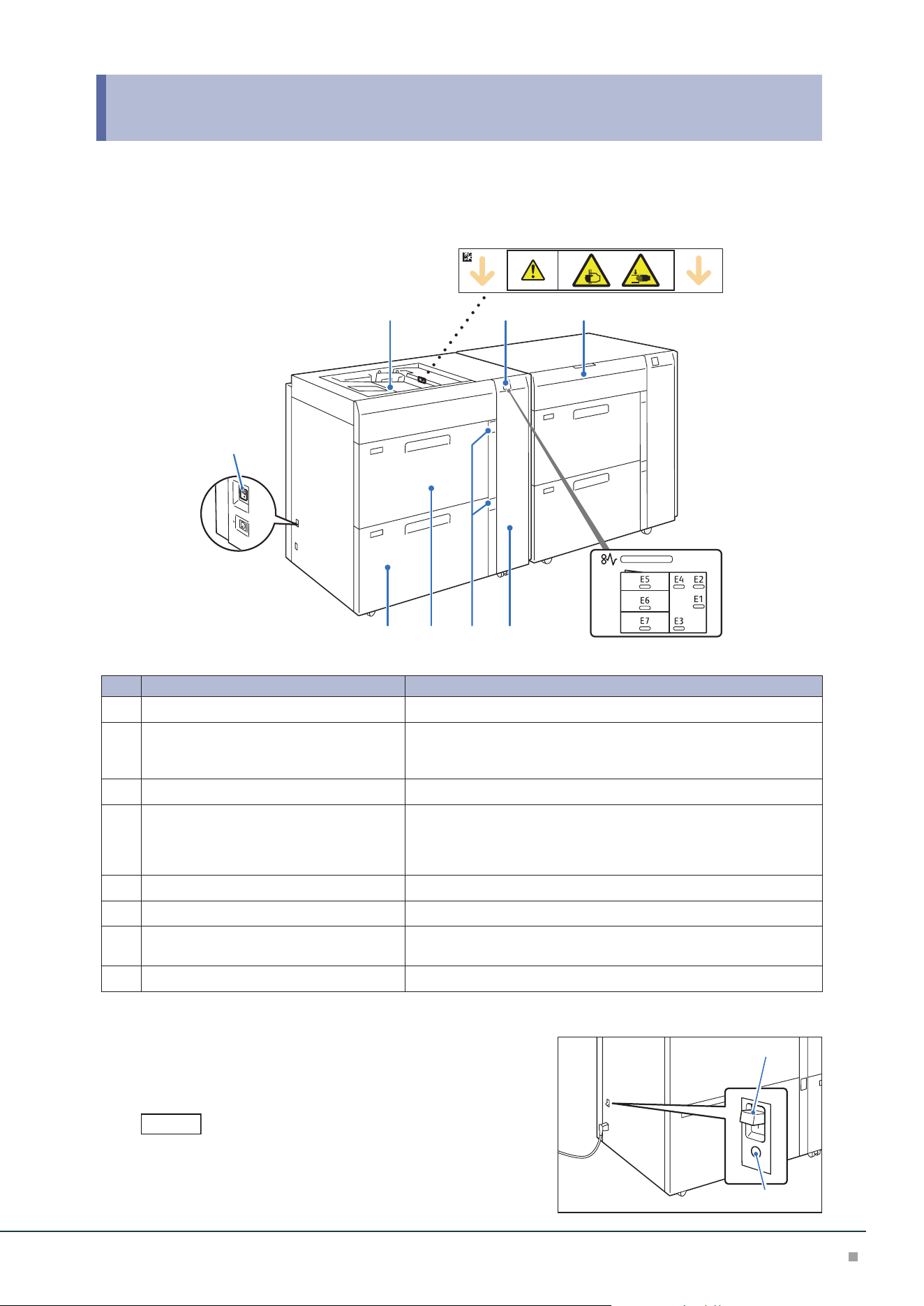
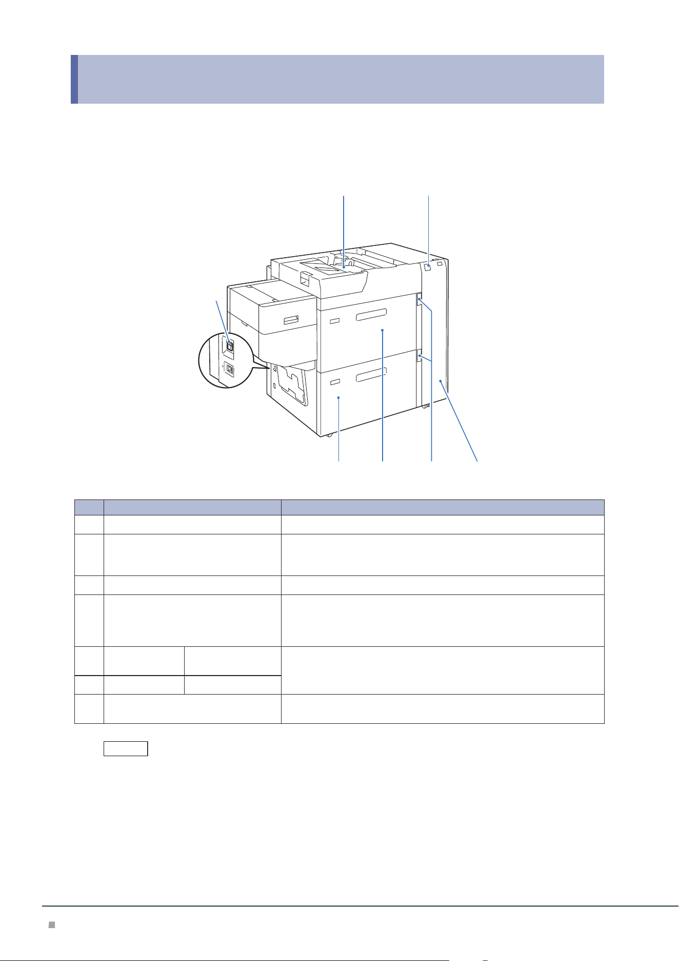
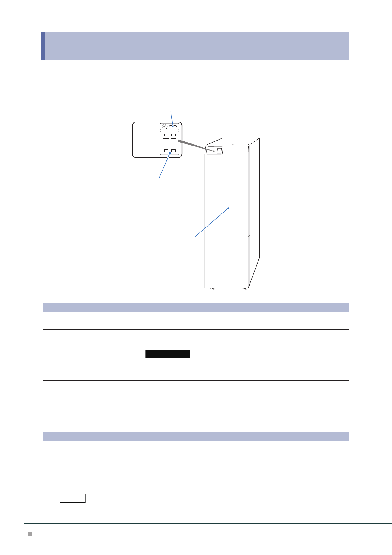
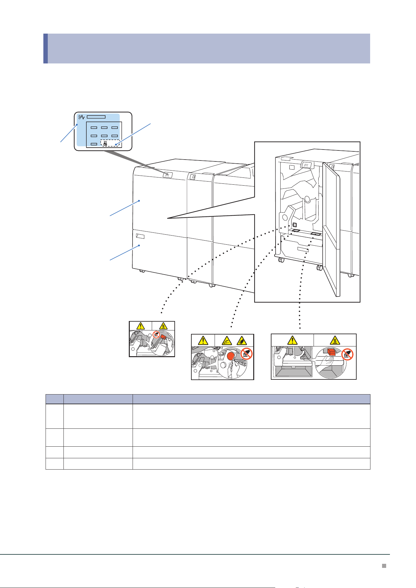
1 High Capacity Feeder
Device Components / Caution Labels
7
21 8
346 5
No. Component Function
1
Bypass Tray (Paper Tray A1/A2-3) Load paper here.
2
Error Indicator When paper jam occurs, the indicator is turned on.
When the priority device indicator (top lamp) blinks, first of all per-
form the paper jam operation.
3
Right Cover Open this cover to clear paper jams.
4
Remaining Volume Indicator When the Paper Tray is in operation, the top lamp is turned on.
You can check the remaining volume of paper with the 4 lamps
(each lamp indicates 25%) at the center.
When Paper Replenish Indicator is turned on, paper is empty.
5
High Capacity Trays (Paper Tray A1/A2-1) Load paper here.
6
High Capacity Trays (Paper Tray A1/A2-2) Load paper here.
7
Ground Fault Interrupter A switch to automatically switch the machine off when a current
leakage is detected.
8
Top cover Pull out this cover to clear paper jams.
Ground Fault Interrupter
When not using for an extended period or when moving the
unit, set the switch to the lower position to turn the ma-
chine power off.
Do not operate the switch under normal circumstances because it is
turned off when a current leakage is detected.
For the current leakage, refer to 'Setup Manual'.
Note
Switch
TEST button
Optional Units Manual
4
Main Specifications
High Capacity Feeder A3
Item Description
Paper size High Capacity Feeder
*1
Standard Size:
Max SRA3 (320 x 450 mm), 12.6×19.2“ (320 x 488 mm), Min
A6
Custom Size:
98 x 148 mm to 330 x 488 mm
Bypass Tray
*2
Standard Size:
Max A3, 11 x 17”, Min A6
Custom Size:
98 x 148 mm to 330 x 488 mm
*3
Paper weight High Capacity Feeder 52 to 350 g/m
2
Bypass Tray 52 to 300 g/m
2*4
Feeding Capacity
*5
/ Number of Tray
High Capacity Feeder 2100 sheets x 2-tray
Bypass Tray 250 sheets
Power supply AC 100-120 V +/- 10 %, 6 A, AC 220-240 V +/- 10 %, 4 A,
50/60 Hz common
Maximum power consumption 880 W
Dimensions W 988 x D 762 x H 992 mm
Weight 211 kg
*6
/ 241kg
*7
*1: When setting main scanning 98 to 182 mm paper, Post Card Kit is required.
*2: Multi Bypass Tray or Multi Bypass Tray for Banner Print (Optional) is required.
*3: Banner sheet printing of up to 330 x 1200 mm is available (Optional).
*4: Banner sheet printing of 82 to 300 g/m
2
is available (Optional).
*5: 82 g/m2 paper
*6: Weight 211 kg is with an optional Multi Bypass Tray or Multi Bypass Tray for Banner Print.
*7: Weight 241 kg is with Paper Feeding Unit for the chained configuration
2nd High Capacity Feeder A3
Item Description
Paper size High Capacity Feeder
*1
Standard Size:
Max SRA3 (320 x 450 mm), 12.6×19.2“ (320 x 488 mm), Min A6
Custom Size:
98 x 148 mm to 330 x 488 mm
Paper weight High Capacity Feeder 52 to 350 g/m
2
Feeding Capacity
*2
/ Number of Tray
High Capacity Feeder 2100 sheets x 2-tray
Power supply AC 100-120 V +/- 10 %, 5 A, AC 220-240 V +/- 10 %, 3 A, 50/60 Hz
common
Maximum power consumption 660 W
Dimensions W 988 x D 762 x H 992 mm
Weight 235 kg
*3
/ 211 kg
*4
*1: When setting main scanning 98 to 182 mm paper, Post Card Kit is required.
*2: 82 g/m2 paper
*3: Weight 235 kg is with Paper Feeding Unit on top of the High Capacity Feeder A3 (shipping configuration)
*4: Weight 211 kg is with an optional Multi Bypass Tray or Multi Bypass Tray for Banner Print.
Optional Multi Bypass Tray or Multi Bypass Tray for Banner Print is required.
Note
High Capacity Feeder
5
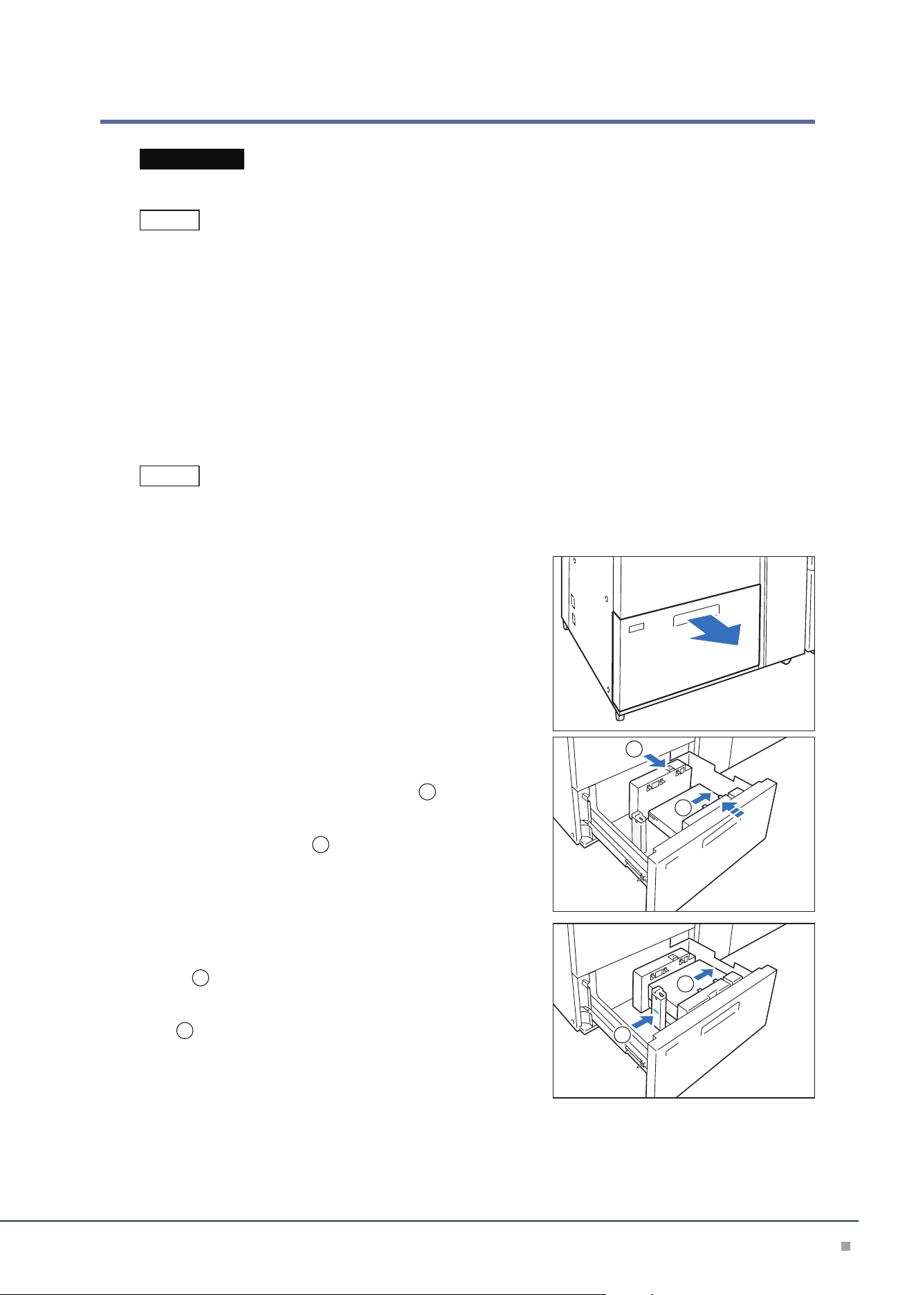
Loading Paper
Loading to High Capacity Tray
Images are printed on the face side of the loaded paper.
Do not load paper above the maximum fill line. It may cause paper jams or machine malfunction.
• If the amount of the loaded paper is 100 sheets or less, the guides apply more pressure to the paper. It may
cause the paper to be distorted, leading to paper jams.
• Position the guides correctly to match the paper size. Incorrectly positioned guides may cause misfeeding and
paper jams.
• In the event power is disconnected while the Paper Tray's bottom plate is rising, the plate may not move up
when the power is recovered. In this case, pull out the Paper Tray, make sure the plate is lowered, and then push
the Paper Tray into the machine slowly and firmly.
• When paper sheets are loaded or fed, the Paper Tray makes a sound of supplying air. This is caused by the Air
Assist function, and not an abnormal noise.
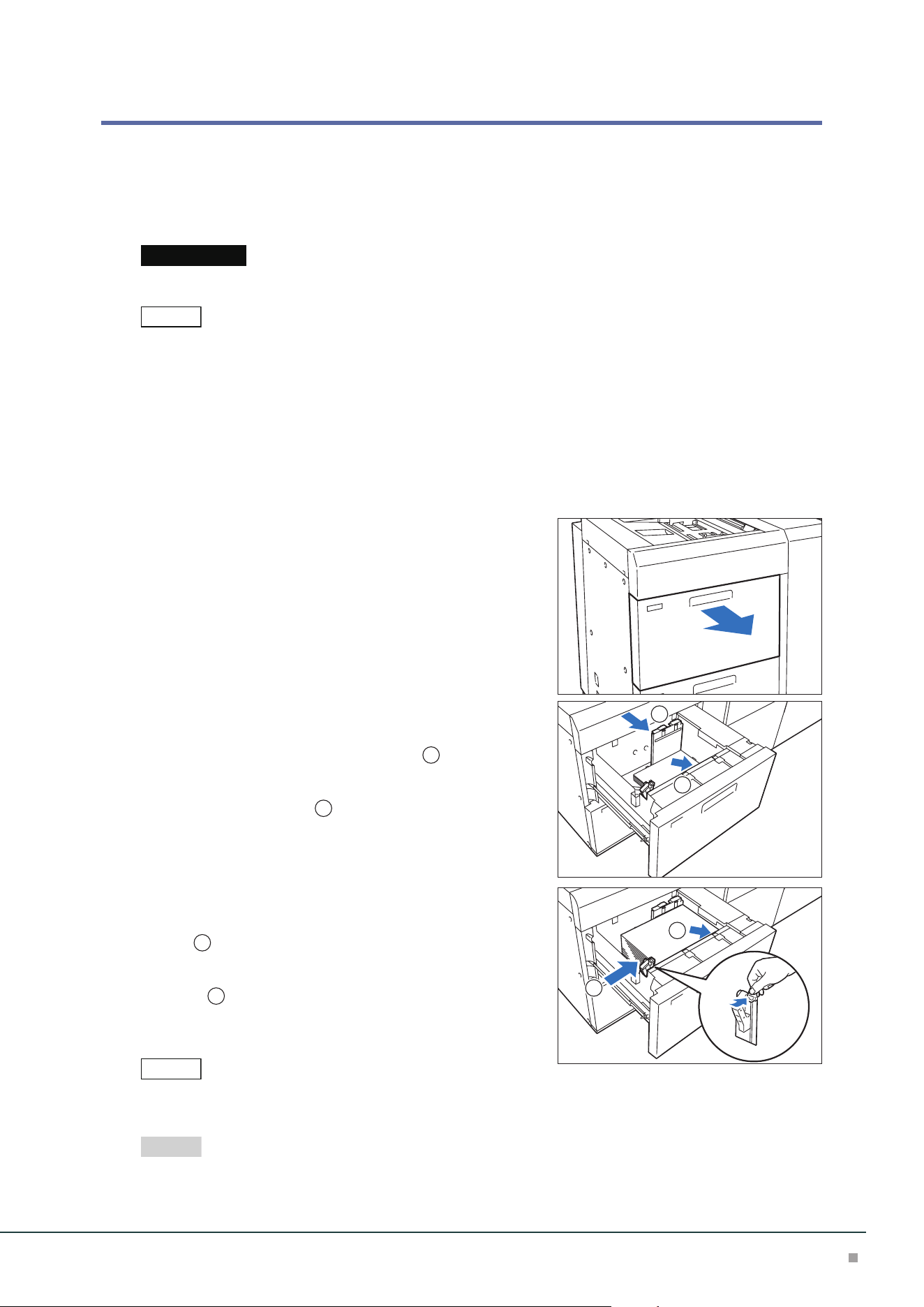
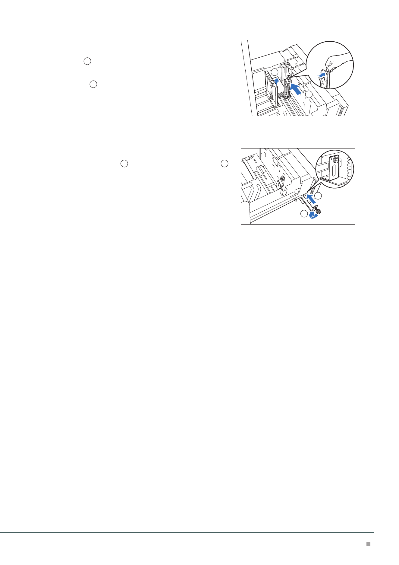
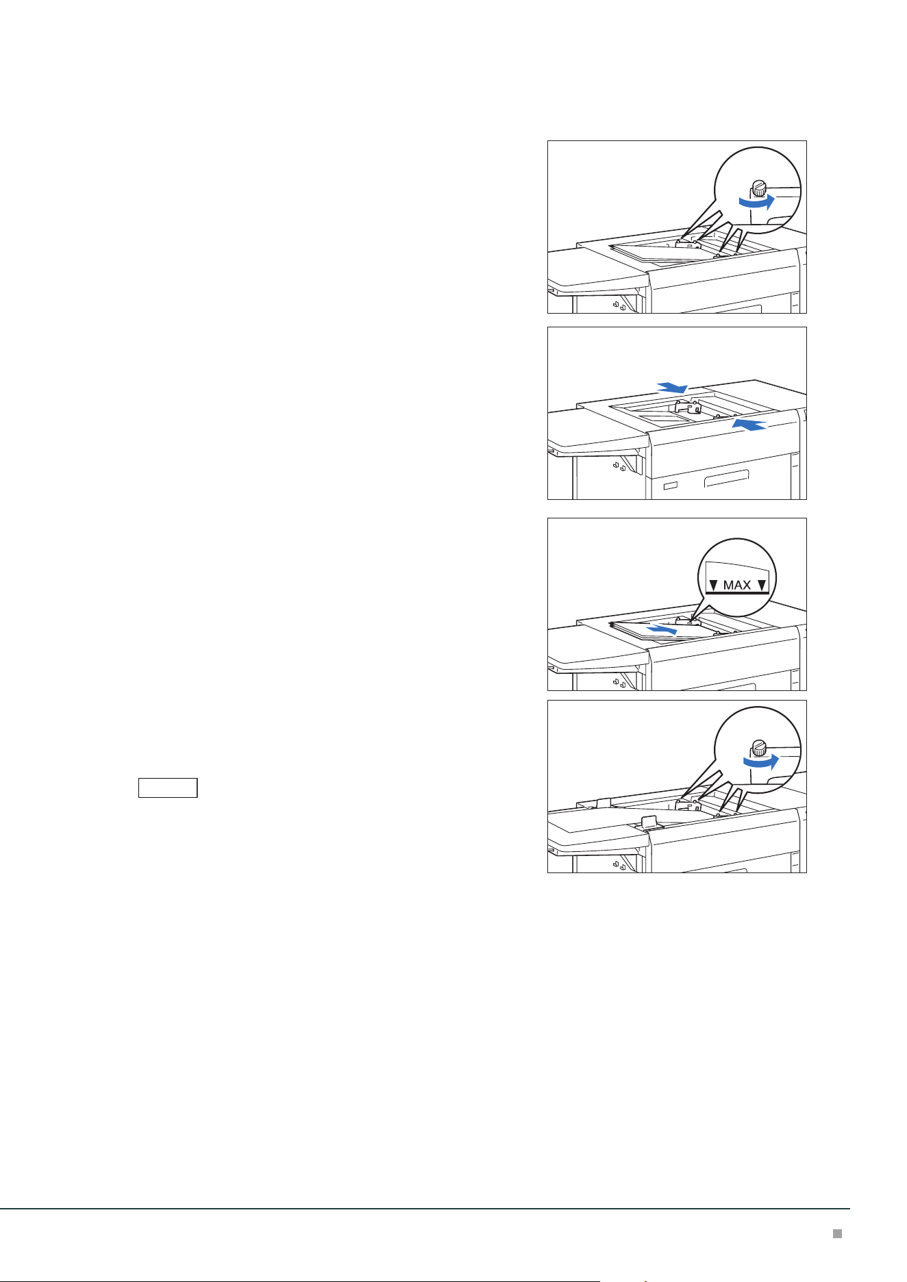
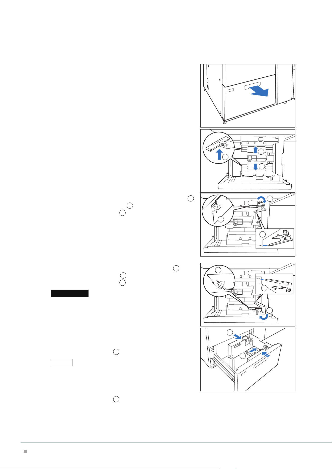
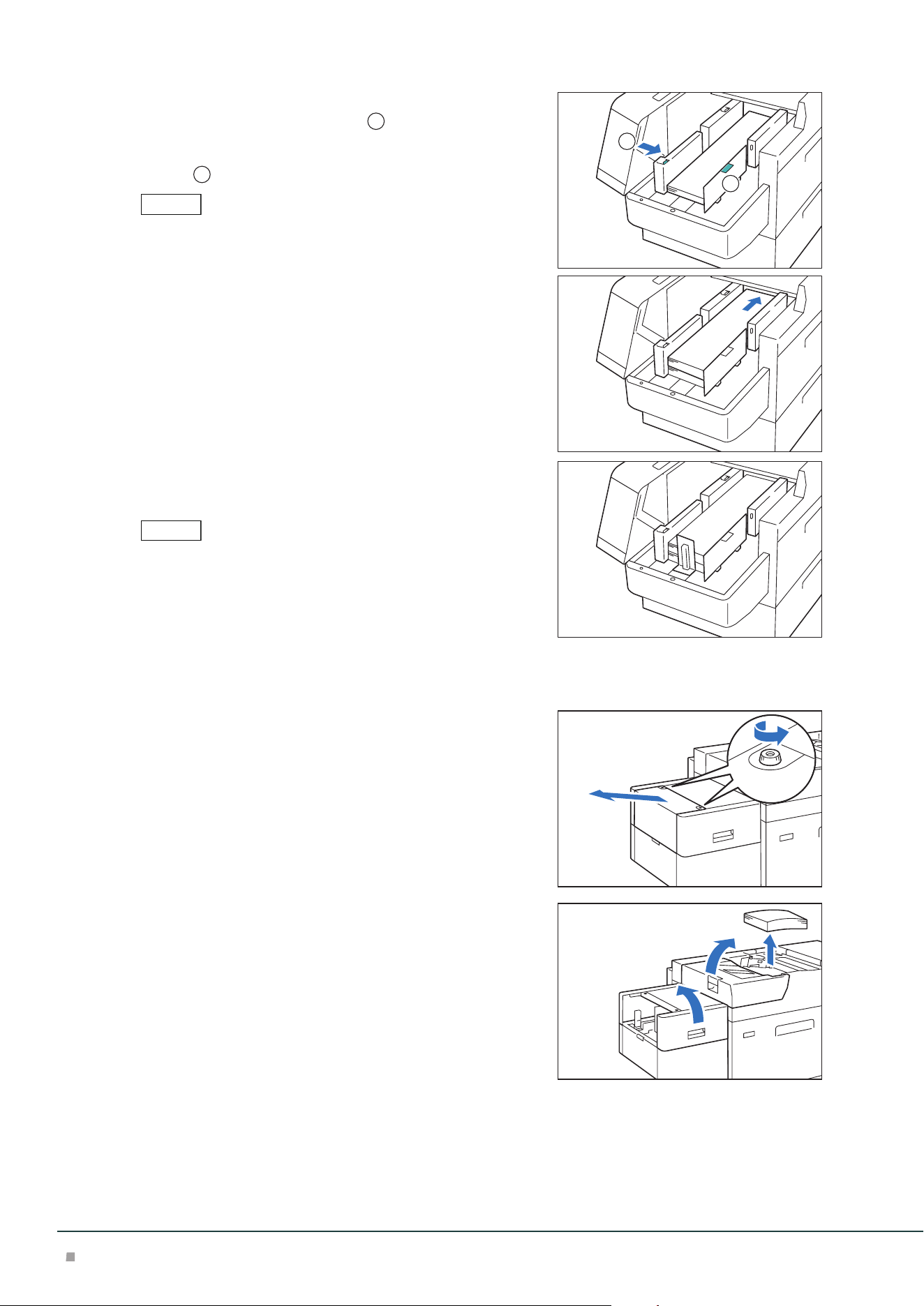
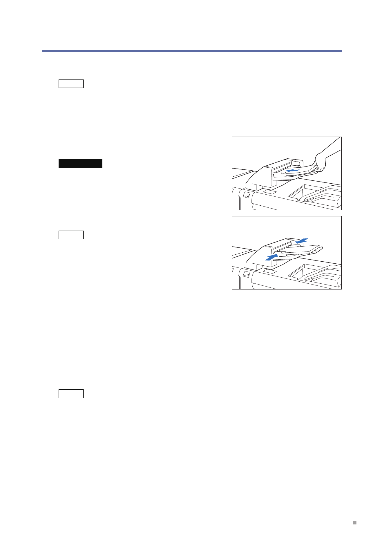
1. Pull out the Paper Tray toward you until it stops.
2. Remove any paper remaining in the Paper Tray.
3. Fan the paper well and load about 100 to 500 sheets
with the printed side facing up, and the paper edges
aligned in the direction of the arrow (
1
).
4. Pinch the long-side paper guide grip and adjust to
the correct paper size (
2
).
5. Load remaining sheets with the printed side facing
up, and align the paper edges in the direction of the
arrow (
1
).
6. Adjust the short-side paper guide to the correct pa-
per size (
2
).
To leave a space, pinch the paper guide grip to move.
To narrow, push the paper guide to move.
Make sure that Paper Feed Precision Lever is set to the Normal position. If printed image is still skewed (misalign-
ment of image on prints) after you load paper in Paper Tray correctly, enable switching of paper feed precision.
"Changing Paper Feeding Accuracy" (p.8)
Important
Note
2
1
1
2
Note
Refer
Optional Units Manual
6
7. Push in the Paper Tray.
Postcard Setting
Attach Post Card Kit to the Paper Tray to load paper with the width of 98 to 181.9 mm.
Do no use Post Card Kit (which does not support 98 to 99.9 mm). Using it can cause misregistration or paper jam.
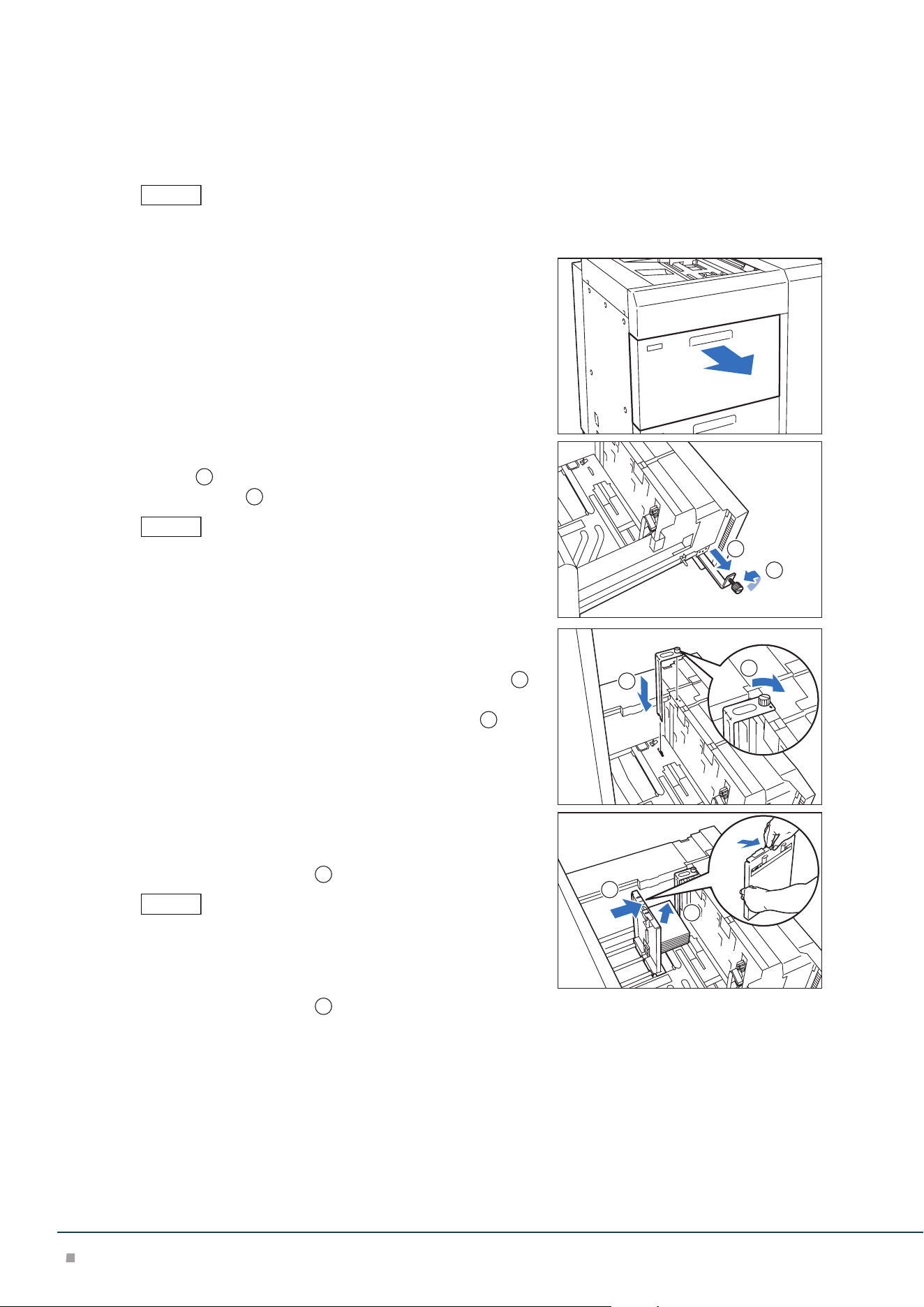
1. Pull out the Paper Tray toward you until it stops.
2. Remove any paper remaining in the Paper Tray.
3. If the Kit is supplied with the Paper Tray, loosen the
screw (
1
) on the left side of the Paper Tray to re-
move the Kit (
2
).
The Postcard Kit is placed in the upper Paper Tray.
4. Insert the small protrusion of the Kit into the notch to
the right side of the bottom of the Paper Tray (
1
).
Align the hole of the Kit with the front Paper Tray
hole and tighten the screw to fasten the Kit (
2
).
5. Load about 100 to 500 sheets of paper with the print-
ed side facing up, and align the paper edges in the
direction of the arrow (
1
).
• Be sure to set them in short edge feed.
• The right side short edge of the set postcard will be the front edge.
6. Pinch the long-side paper guide grip and adjust to
the correct paper size (
2
).
Note
2
1
Note
1
2
Note
1
2
High Capacity Feeder
7
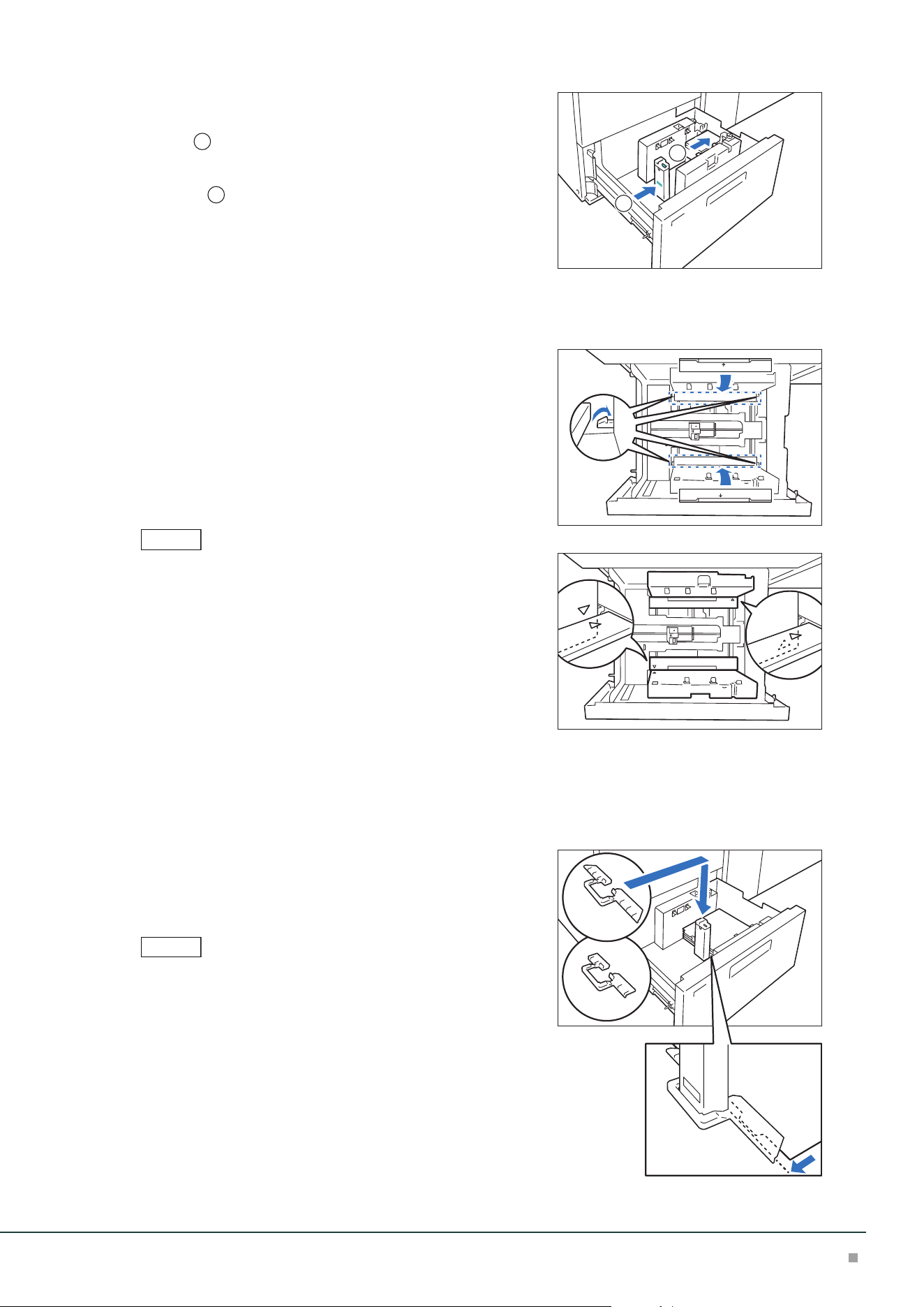
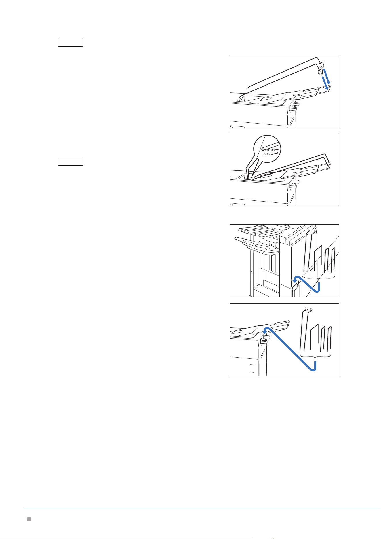
7. Load remaining sheets with the printed side facing
up, and align the paper edges in the direction of the
arrow (
1
).
8. Adjust the short-side paper guide to the correct pa-
per size (
2
).
To leave a space, pinch the paper guide grip to move.
To narrow, push the paper guide to move.
9. Push in the Paper Tray.
10. To remove the Kit from the Paper Tray, loosen the screw completely and then remove the
Kit.
11. Store the Kit in place by inserting it from the left side
of the Paper Tray (
1
) and tightening the screw (
2
).
Special Media Setting
■Hole Punched Paper
Orientation: Place the holes of paper on the right side when you face the front side of machine.
■Precut Tab
Orientation: Place the tabs of paper on the left side when you face the front side of machine.
2
1
1
2
Optional Units Manual
8
Changing Paper Feeding Accuracy
Enabling this function may improve print displacement when images are skewed (print position is
displaced) even though plain paper with the paper weight of 220 g/m
2
or less is correctly loaded.
• If this function is enabled when paper other than thick paper and plain paper is used, the machine cannot feed
the paper properly, resulting in paper jams.
• It is not effective when the Postcard Kit is used.
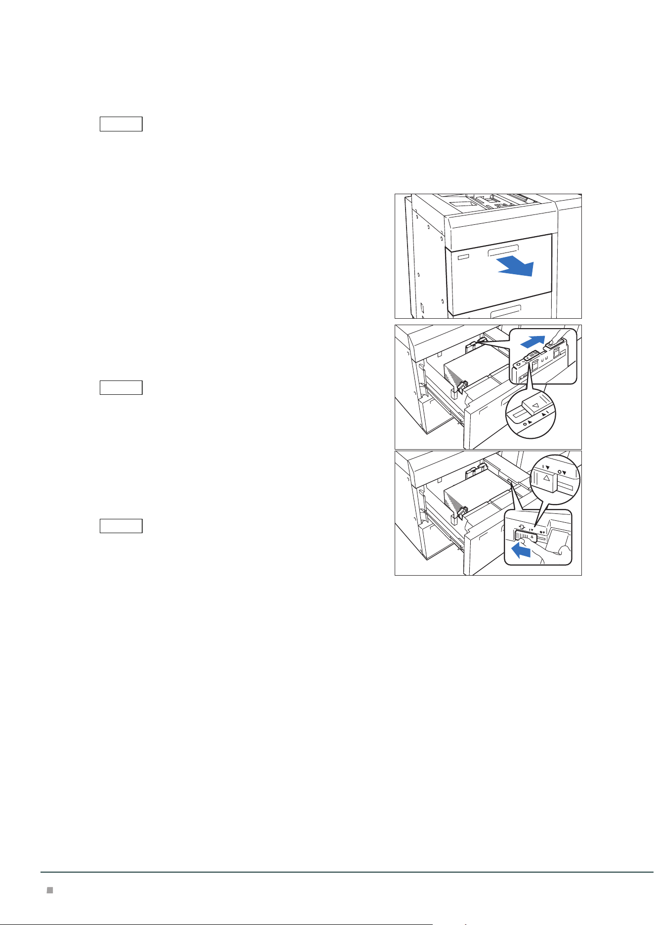
1. Pull out the Paper Tray until it stops.
2. Move the lever at the top of the long-side paper guide
to the rightmost position (<I> position) to enable the
changing.
To reset the setting, move the lever to the leftmost position.
3. If the accuracy of paper feeding is not improved even
if 2 is performed, move the lever at the right front to
the rearmost position (<I> position) to enable the
changing.
To reset the setting, move the lever to the foremost position.
4. Push in the Paper Tray.
After using the paper in question, return the lever to the
normal position <o>.
Note
Note
Note
High Capacity Feeder
9
Loading to Bypass Tray
Images are printed on the face side of the loaded paper.
Do not load paper above the maximum fill line. It may cause paper jams or machine malfunction.
• If the paper guide width is narrower or wider than the paper, it may cause paper jams.
• In the case of coated paper, only one sheet can be loaded.
The image quality and paper feeding capability are not guaranteed when more than one sheet is loaded.
Slide Type
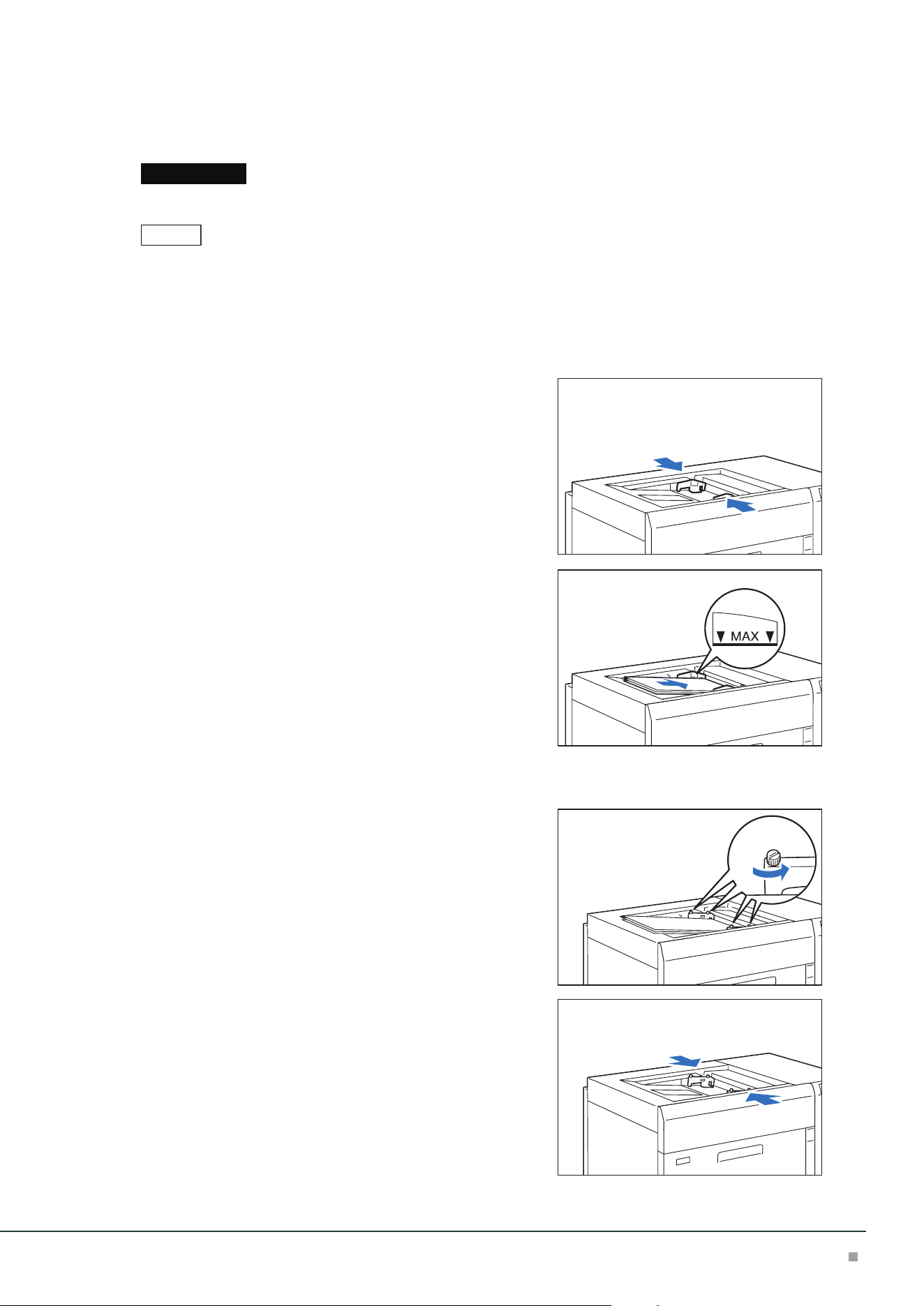
1. Adjust the paper guide to the size of loaded paper.
2. Fan the paper well and insert it along the paper guide
all the way until it touches the back, with the printed
side facing up.
3. When custom size paper is loaded, make fine-adjust-
ment of the paper guide based on the paper size.
Flexible Type (for Long Paper)
1. Loosen the 4 screws of the paper guide.
2. Hold the center of the paper guide and adjust it to the
size of loaded paper.
Important
Note
Optional Units Manual
10
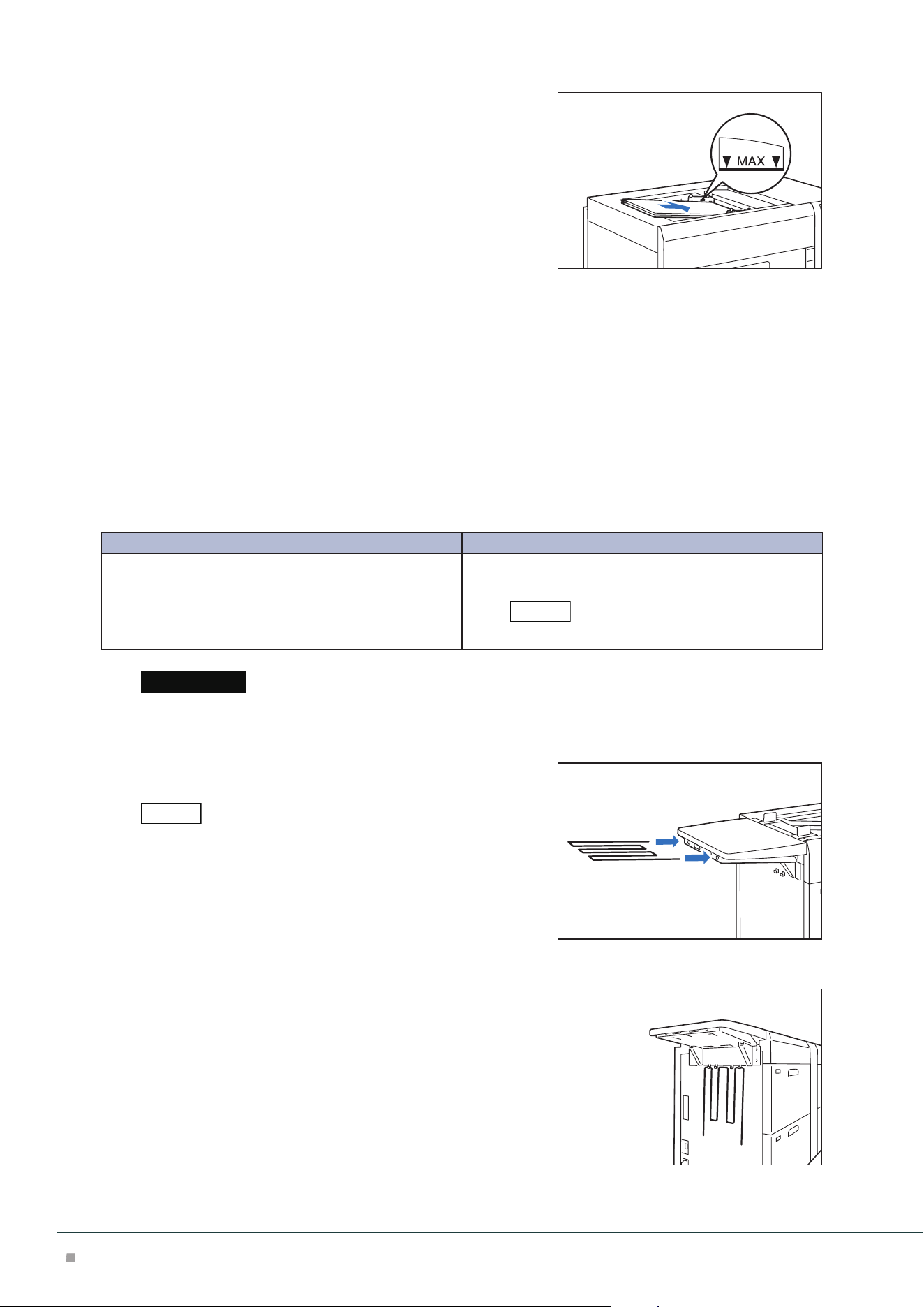
3. Fan the paper well and insert it along the paper guide
all the way until it touches the back, with the printed
side facing up.
4. Secure the 4 screws of the paper guide.
Special Media Setting
■Hole Punched Paper
Orientation: Place the holes of paper on the right side when you face the front side of machine.
■Precut Tab
Orientation: Place the tabs of paper on the left side when you face the front side of machine.
■Postcards
Orientation: SEF
Bypass Tray for Long Paper
Load long paper in the Bypass Tray without its rear edge sticking out.
Paper size (mm) Tray capacity (sheets)
Width: 210 to 330.2
Length: 488.1 to 1,200
Up to 729 mm: 150
More than 729.1 mm : 10
This value applies if 82 g/m2 paper is used.
When paper exceeding the tray capacity is loaded, the Extension Kit may get broken.
■Extension Kit
(1) Insert the extension tray all the way in.
Insert it until it stops.
■ When not in use
Hang them on the holder at the side.
Note
Important
Note
High Capacity Feeder
11
■Loading Paper
1. Loosen the 4 screws of the front paper guide.
2. Hold the center of the front paper guide and adjust it
to the size of loaded paper.
3. Fan the paper well and insert it along the front paper
guide all the way until it touches the back, with the
printed sidefacing up.
4. Fasten the 4 screws of the front paper guide, and
then finetune the rear paper guide to match the pa-
per size.
The rear paper guide is removable. Also, it can be used irrespective
of the top and bottom orientation. Install it in the direction such that
the metal surface touches paper.
Note
Optional Units Manual
12
■Alignment
When using long paper with the length of 729 mm or less, auto alignment adjustment can be per-
formed by means of Inline Sensor.
If auto alignment ends abnormally (image skew angle is 5 mm or more), you need to mitigate the image skew by
using Individual Settings before proceeding with auto alignment.
When using long paper with the length of 729 mm or more, auto alignment adjustment cannot be
performed, and therefore adjust alignment by using Individual Settings.
When using long paper with the length of 729 mm or more, if the image skew angle is large (8 mm or
more), first mitigate the image skew by adjusting paper guide position, and then proceed with align-
ment adjustment with Individual Settings.
■ Image skew angle is large (8 mm or more)
• Load a single sheet of paper only before proceeding with the adjustment.
• Load paper so that the front edge touches the guide.
• If the paper you use is curled, skew adjustment may not be correctly applied. If paper is curled, first perform curl
correction using Media Library before you can perform skew adjustment.
1. Fasten the 4 screws of the front paper guide, and then fine tune the rear paper guide to
match the paper size.
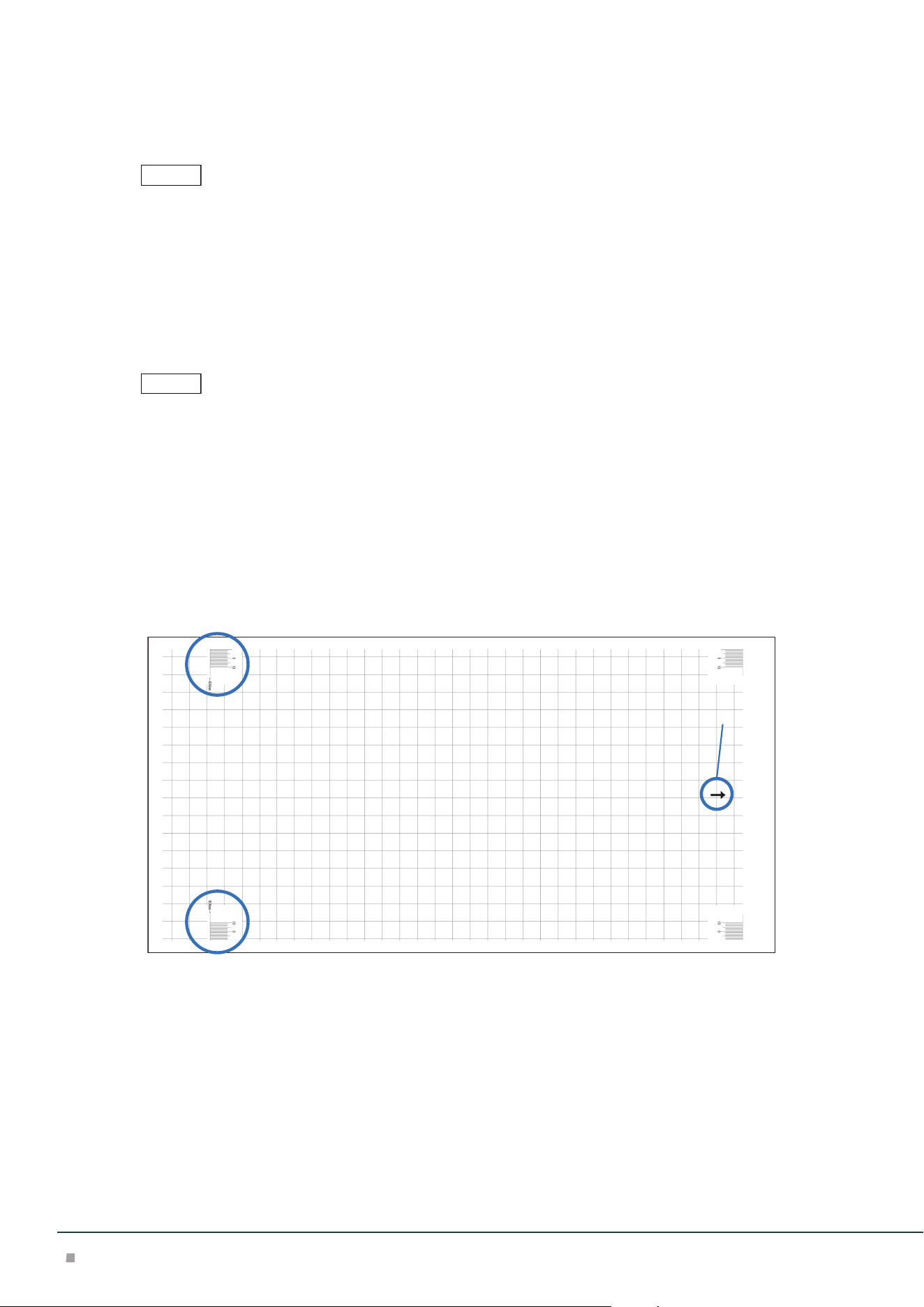
2. Print a sample file whose paper size is near to the one you want to use.
Sample files are stored in the “D:\PrtSrvPublic\UtilityFiles\TKOR\skew” folder for Print Server.
3. Check the skew of the sample image you printed.
Feed direction
Use the graduation at the point of "606 mm" in the rear edge of paper or at the center of paper to
measure the amount of skew against the paper sheet.
No adjustment is needed if the graduation is at right angle against the paper sheet.
Note
Note
High Capacity Feeder
13
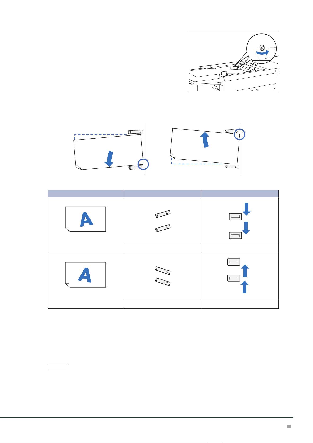
4. Loosen the 4 screws of the front paper guide.
5. Use the right/left front edge of paper as the pivot point (right front edge if the skew is ori-
ented leftward, or left front edge if the skew is oriented rightward) to move the rear edge
of paper to the position corresponding to the skew amount.
Image Front paper guide Rear paper guide
Skew is oriented leftward
Right side is upper Left side is lower Move downward
Skew is oriented rightward
Right side is lower Left side is upper Move upward
6. Fasten the 4 screws of the front paper guide, and then fine tune the rear paper guide to
match the paper size.
7. Print a sample file whose paper size is near to the one you want to use.
8. If the quality of the printed output is satisfactory, load the required number of pager sheets
in the Paper Ttray. If adjustment is required, repeat Steps 3 to 7.
In preparation for the next time you use the same paper, it is recommended you note the skew amount.
Note
Optional Units Manual
14
Paper Jams
The error indicator at the top of the machine is turned on. When the priority device indicator (top lamp) blinks,
first of all perform the paper jam operation.
If paper is jammed, the machine stops and an alarm sounds. Follow the instructions displayed on
the screen to remove the jammed paper.
Gently remove the paper being careful not to tear it. If paper is torn while it is being removed from
the machine, remove all the torn pieces making sure that none remain inside the machine.
When you have finished clearing the paper jam, printing is resumed from the state before the pa-
per jam occurred.
Clear the paper jams while the machine is on.
Paper Tray
1. Remove the jammed paper.
When Indicator E5 is Turned on .................................................................................................p.14
When Indicator E6 is Turned on .................................................................................................p.14
When Indicator E7 is Turned on .................................................................................................p.15
■When Indicator E5 is Turned on
(1) Open the Upper Cover and remove all the jammed papers
and papers loaded on the tray.
(2) Close the cover.
(3) Align the 4 corners of the removed papers and load them
again.
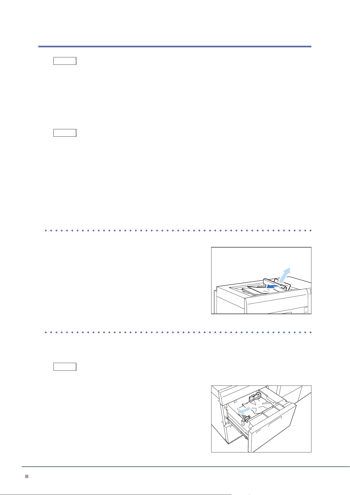
■When Indicator E6 is Turned on
(1) Pull out the Paper Tray A1/A2-1 toward you until it stops.
Confirm that no paper is jammed inside the Right Cover before pulling it out.
(2) Remove the jammed paper.
(3) Confirm the paper guide position and push in the Paper
Tray.
Note
Note
Note
High Capacity Feeder
15
■When Indicator E7 is Turned on
(1) Pull out the Paper Tray A1/A2-2 toward you until it stops.
Confirm that no paper is jammed inside the Right Cover before pulling it out.
(2) Remove the jammed paper.
(3) Confirm the paper guide position and push in the Paper
Tray.
Inside of the Right Cover
(at Single or Right Side at Continuous Feed Configuration)
1. Open the Right Cover.
2. Remove the jammed paper.
When Indicator E1 is Turned on .................................................................................................p.15
When Indicator E2 is Turned on .................................................................................................p.15
When Indicator E3 is Turned on .................................................................................................p.16
When Indicator E4 is Turned on .................................................................................................p.16
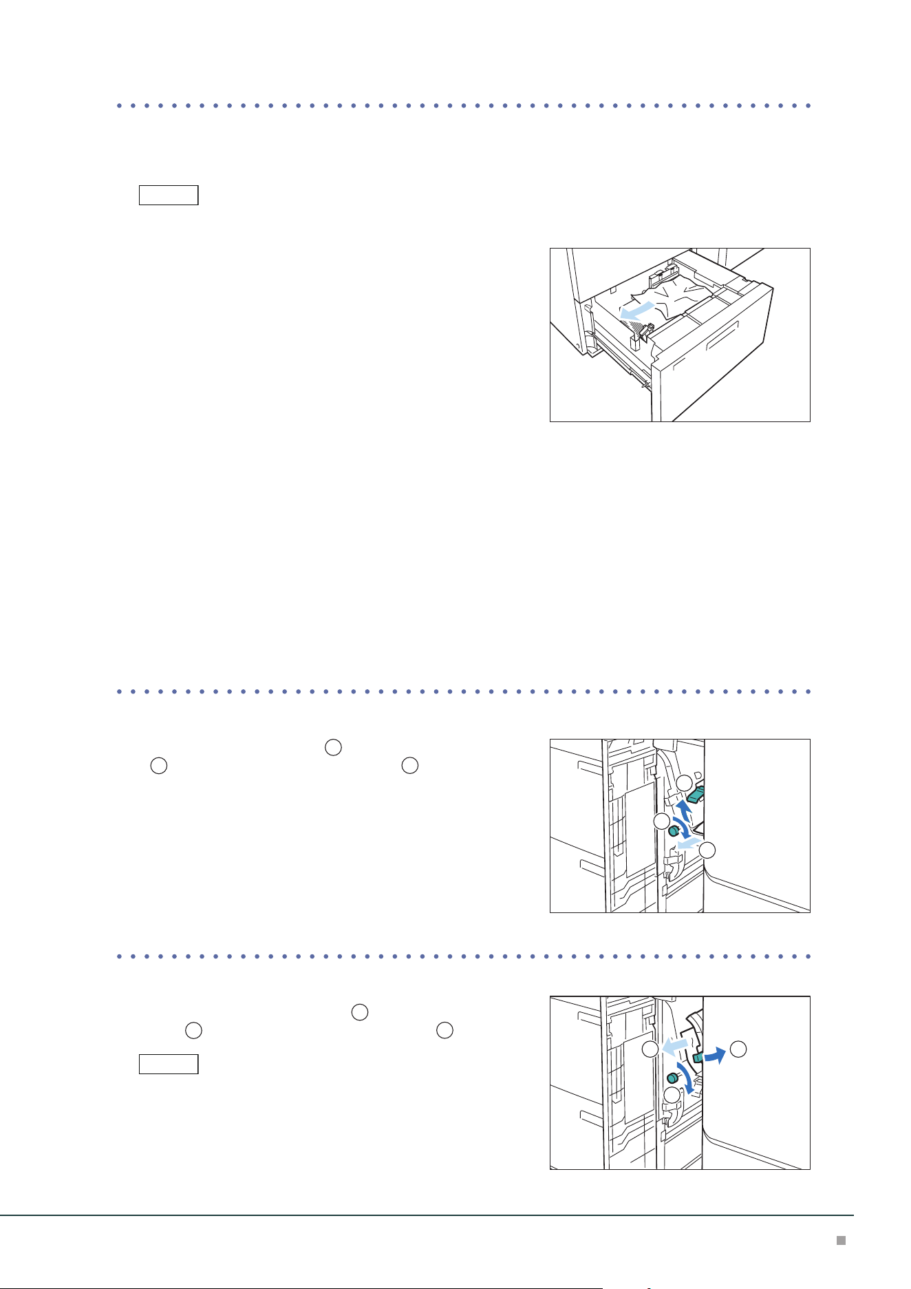
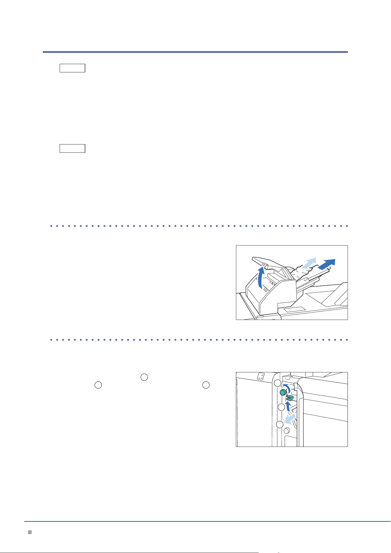
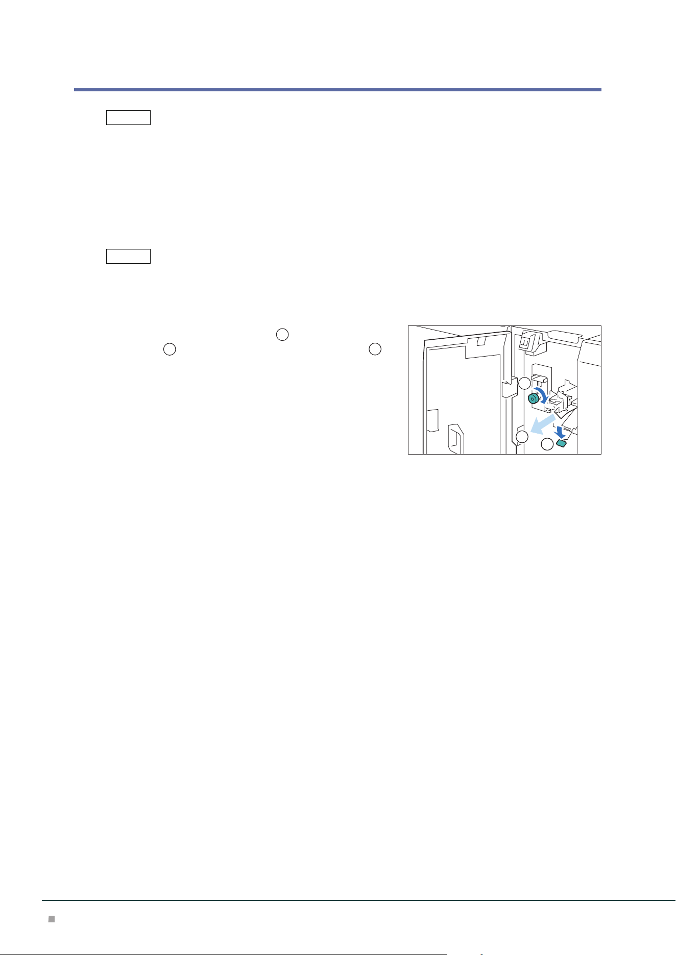
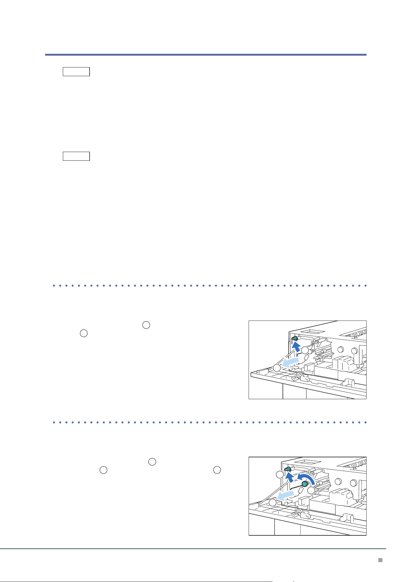
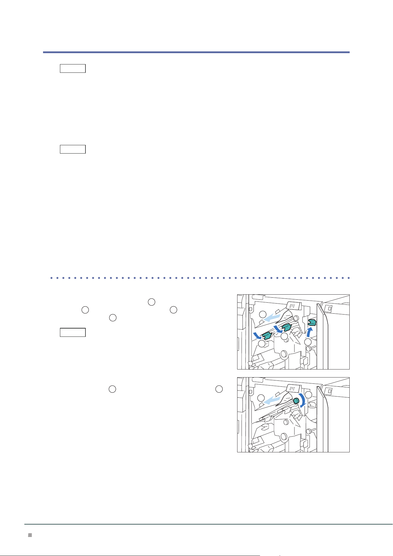
■When Indicator E1 is Turned on
(1) Open lever [1d] upward (
1
), turn knob [1c] clockwise
(
2
), and remove the jammed paper (
3
).
(2) Return lever [1d].
■When Indicator E2 is Turned on
(1) Open lever [1a] to the right (
1
), turn knob [1c] clock-
wise (
2
), and remove the jammed paper (
3
).
Turn knob [1c] 3 times or more.
(2) Return lever [1a].
Note
3
1
2
Note
3
1
2
Optional Units Manual
16
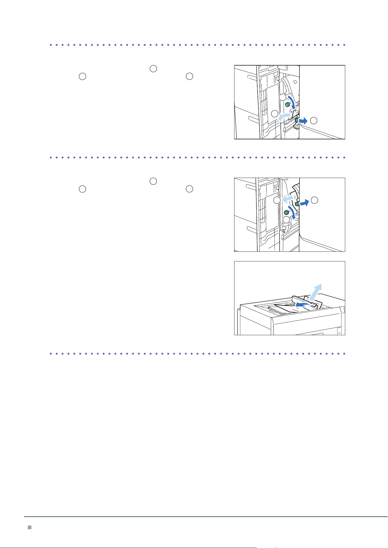
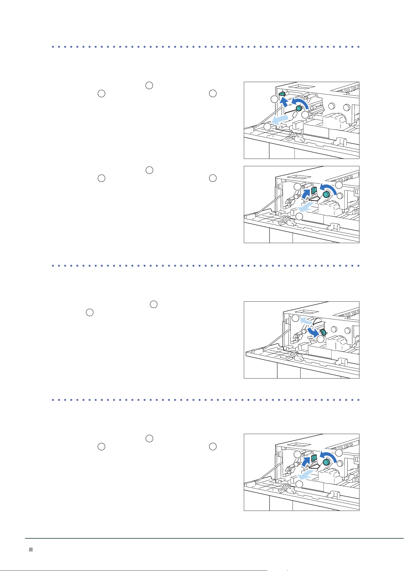
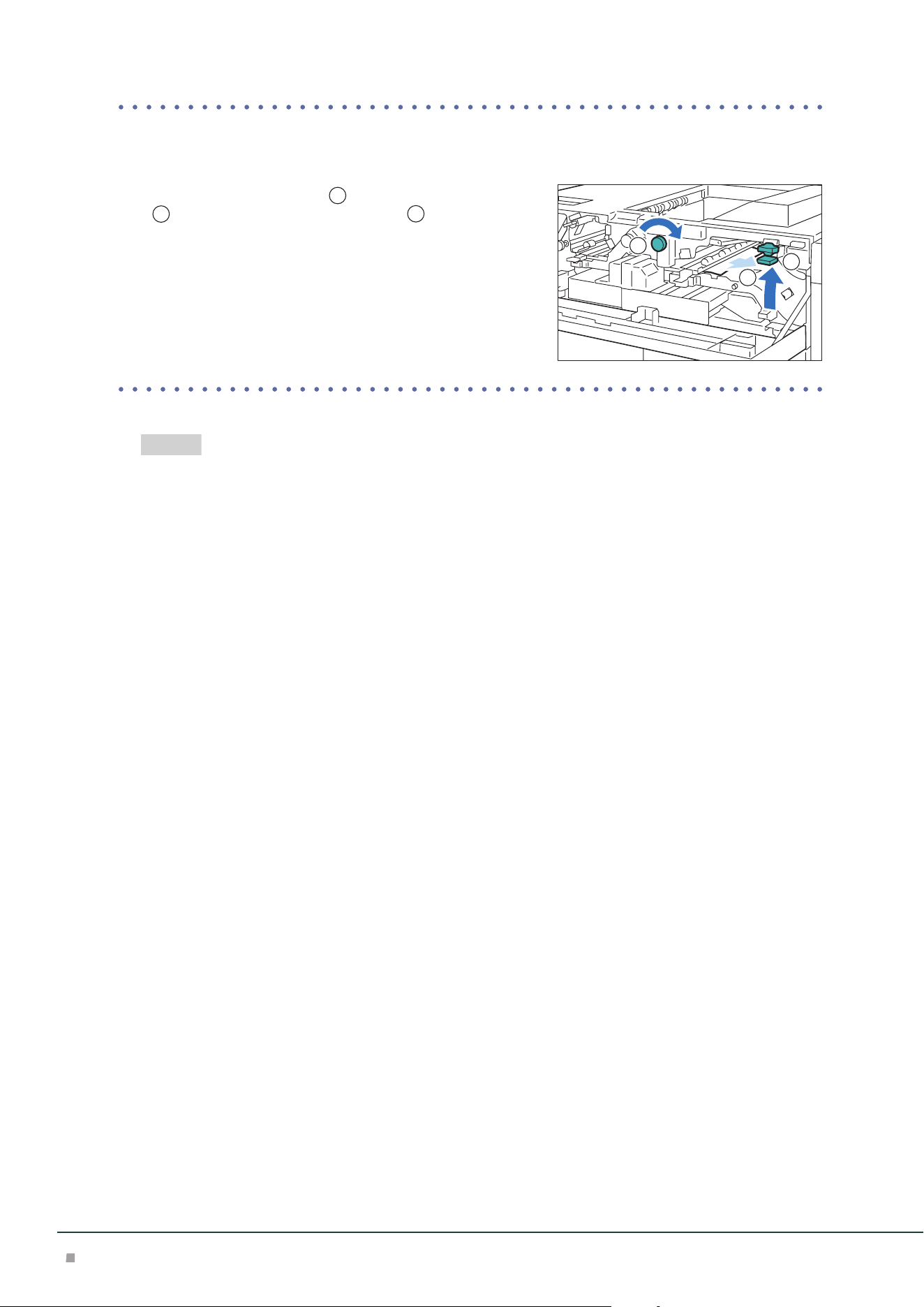
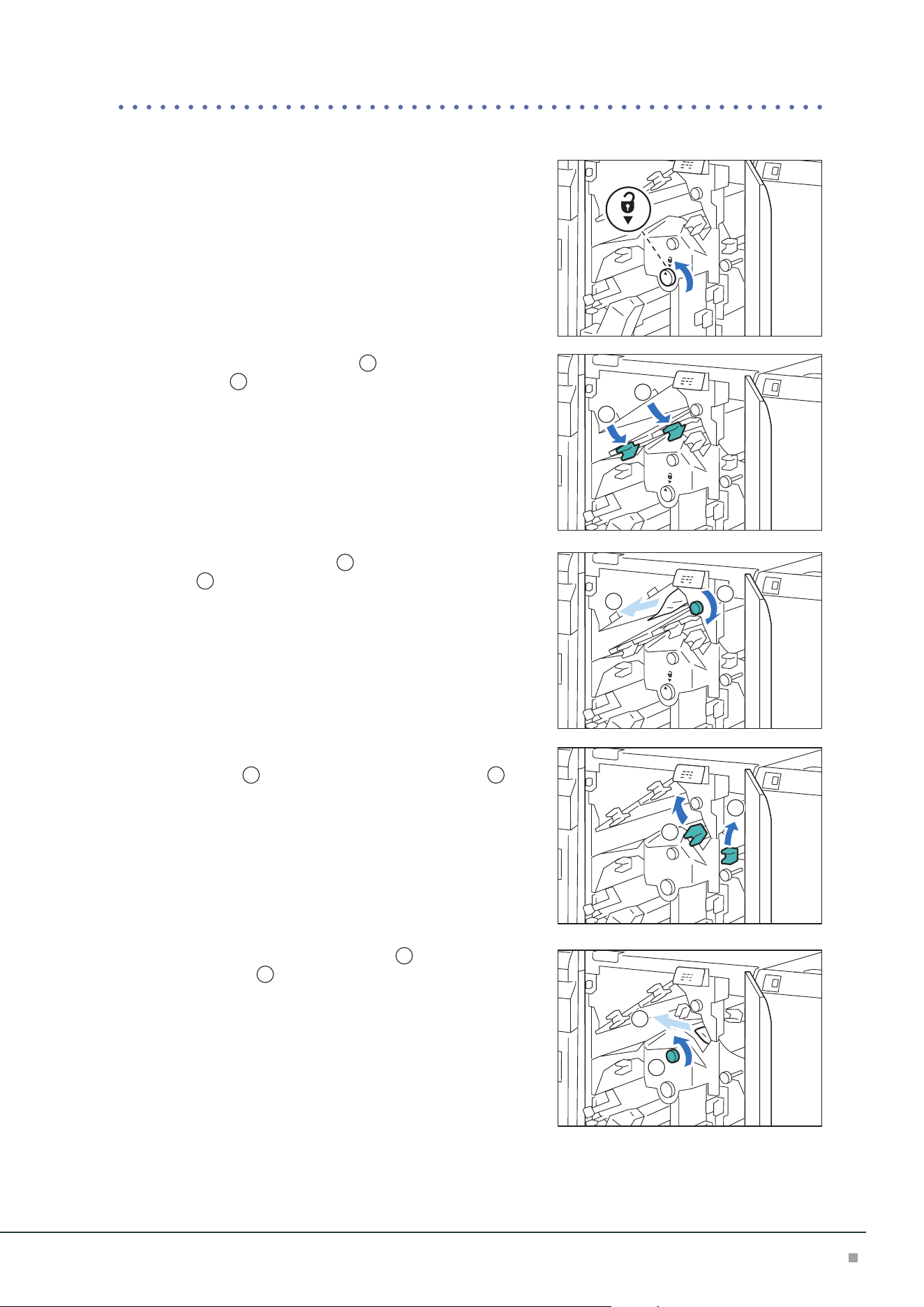
■When Indicator E3 is Turned on
(1) Open lever [1b] to the right (
1
), turn knob [1c] clock-
wise (
2
), and remove the jammed paper (
3
).
(2) Return lever [1b].
■When Indicator E4 is Turned on
(1) Open lever [1a] to the right (
1
), turn knob [1c] clock-
wise (
2
), and remove the jammed paper (
3
).
(2) If you have difficulty in removing the papers, open the Up-
per Cover and remove the jammed paper.
(3) Return lever [1a].
3. Close the cover.
3
2
1
3
1
2
High Capacity Feeder
17
Inside of the Right Cover
(Left Side at Continuous Feed Configuration)
1. Open the Right Cover.
2. Remove the jammed paper.
When Indicator E1 is Turned on .................................................................................................p.17
When Indicator E2 is Turned on .................................................................................................p.17
When Indicator E3 is Turned on .................................................................................................p.18
When Indicator E4 is Turned on .................................................................................................p.18
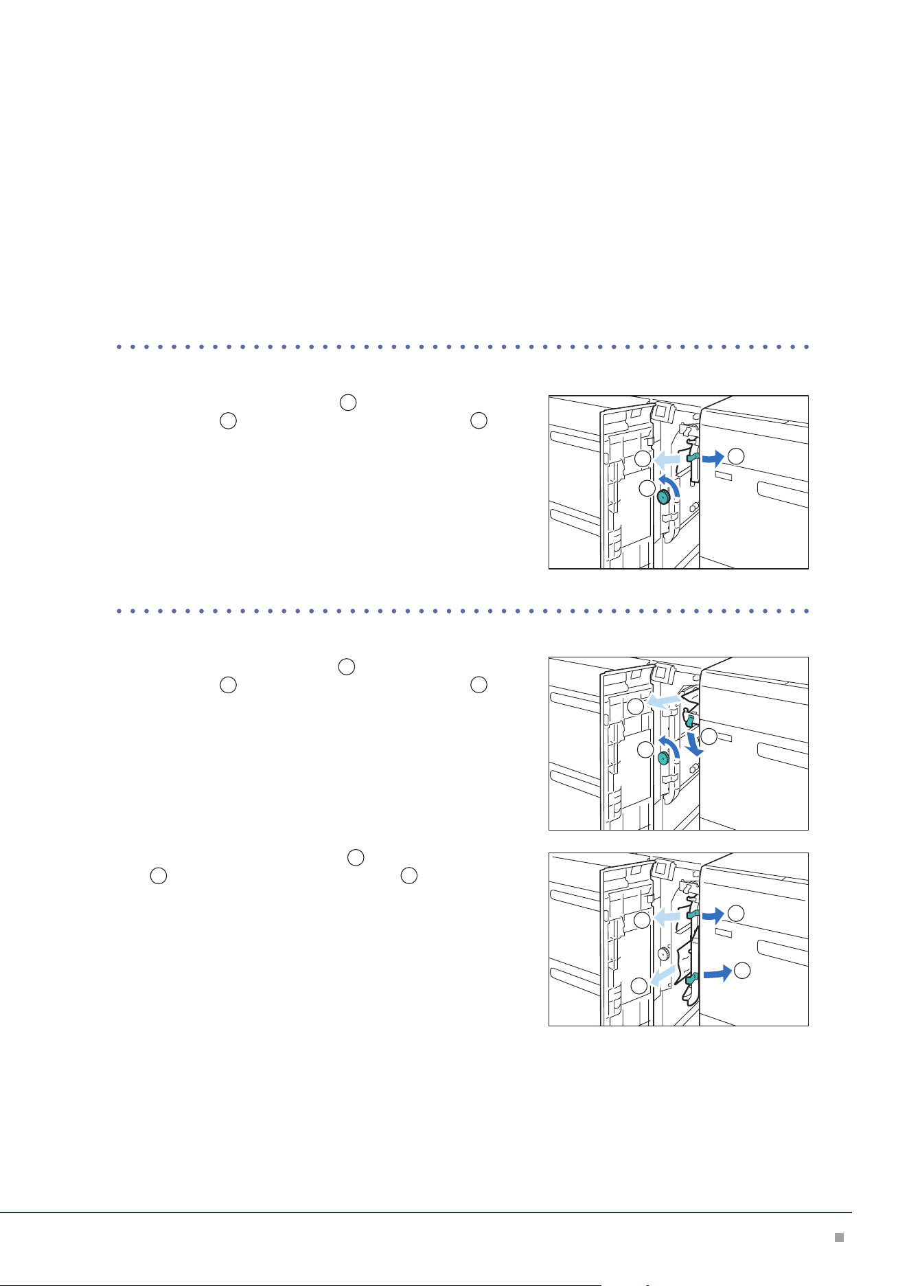
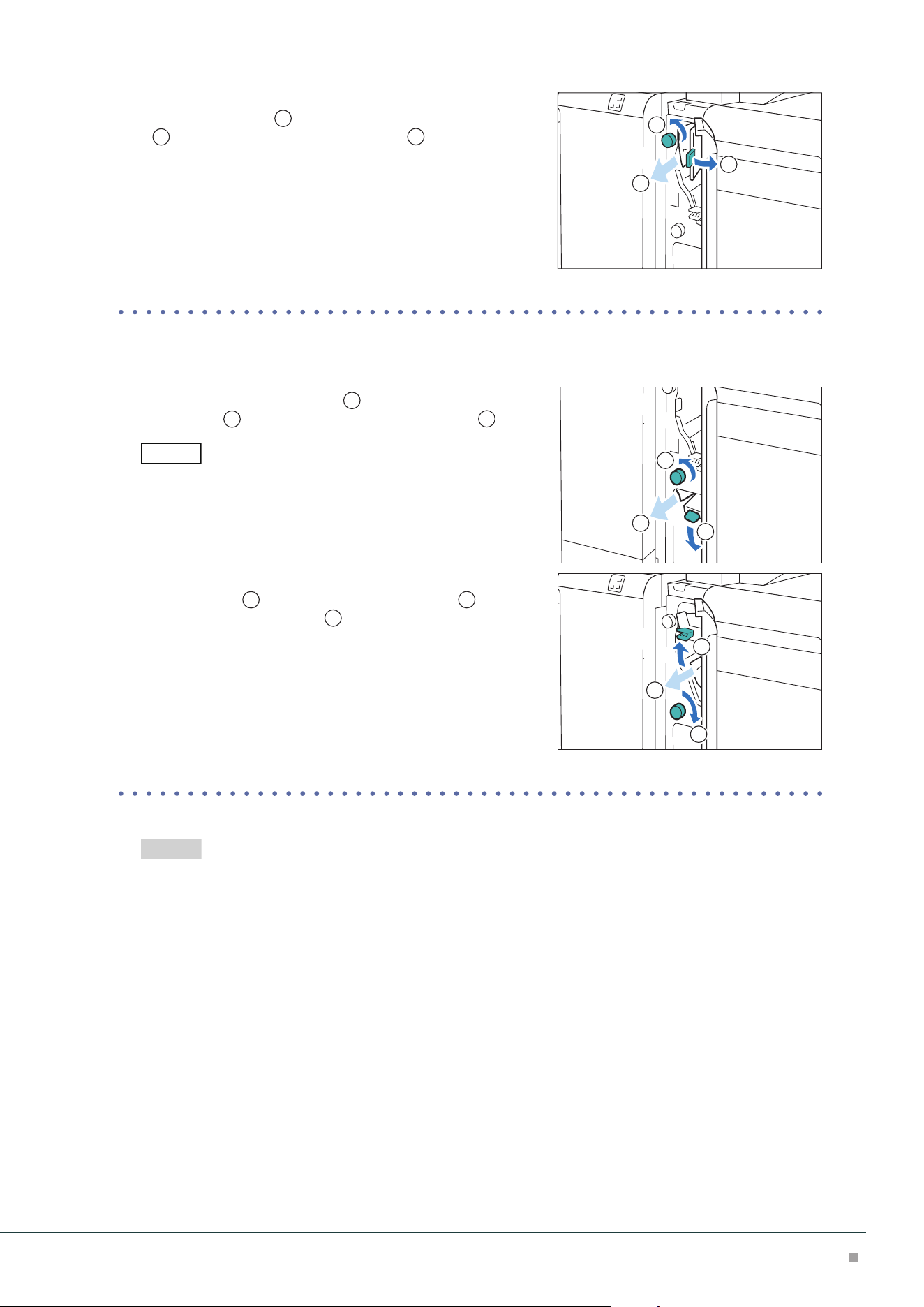
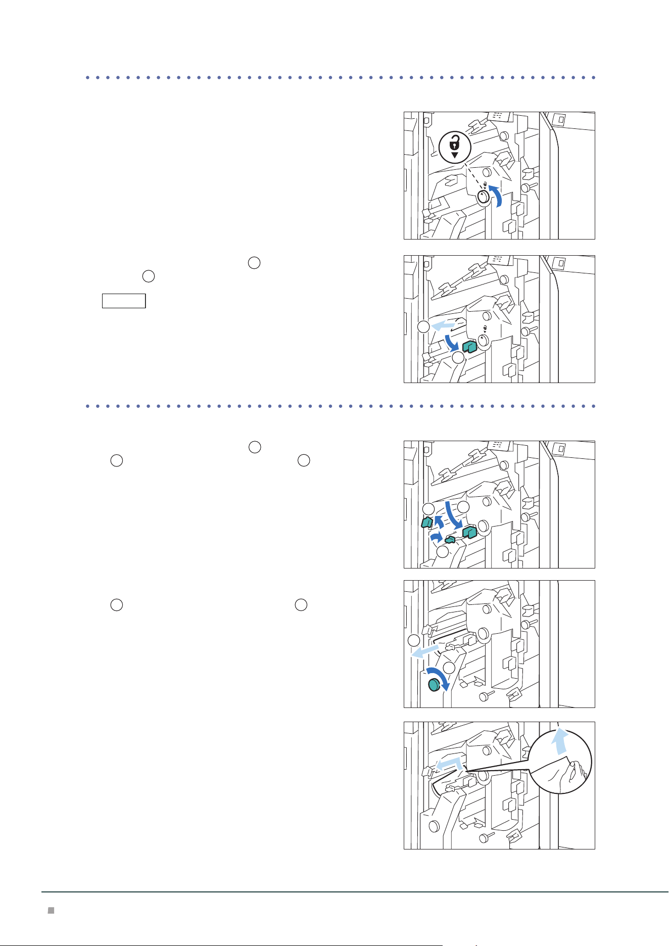
■When Indicator E1 is Turned on
(1) Open lever [1a] to the right (
1
), turn knob [1c] counter-
clockwise (
2
), and remove the jammed paper (
3
).
(2) Return lever [1a].
■When Indicator E2 is Turned on
(1) Open lever [1d] downward (
1
), turn knob [1c] counter-
clockwise (
2
), and remove the jammed paper (
3
).
(2) Return lever [1d].
(3) Open lever [1a] to the right (
1
), lever [1b] to the right
(
2
), and remove the jammed paper (
3
).
(4) Return lever [1a] and [1b].
3
1
2
3
1
2
3
3
1
2
Optional Units Manual
18
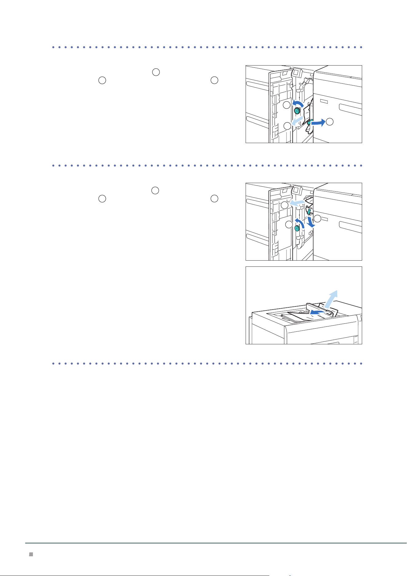
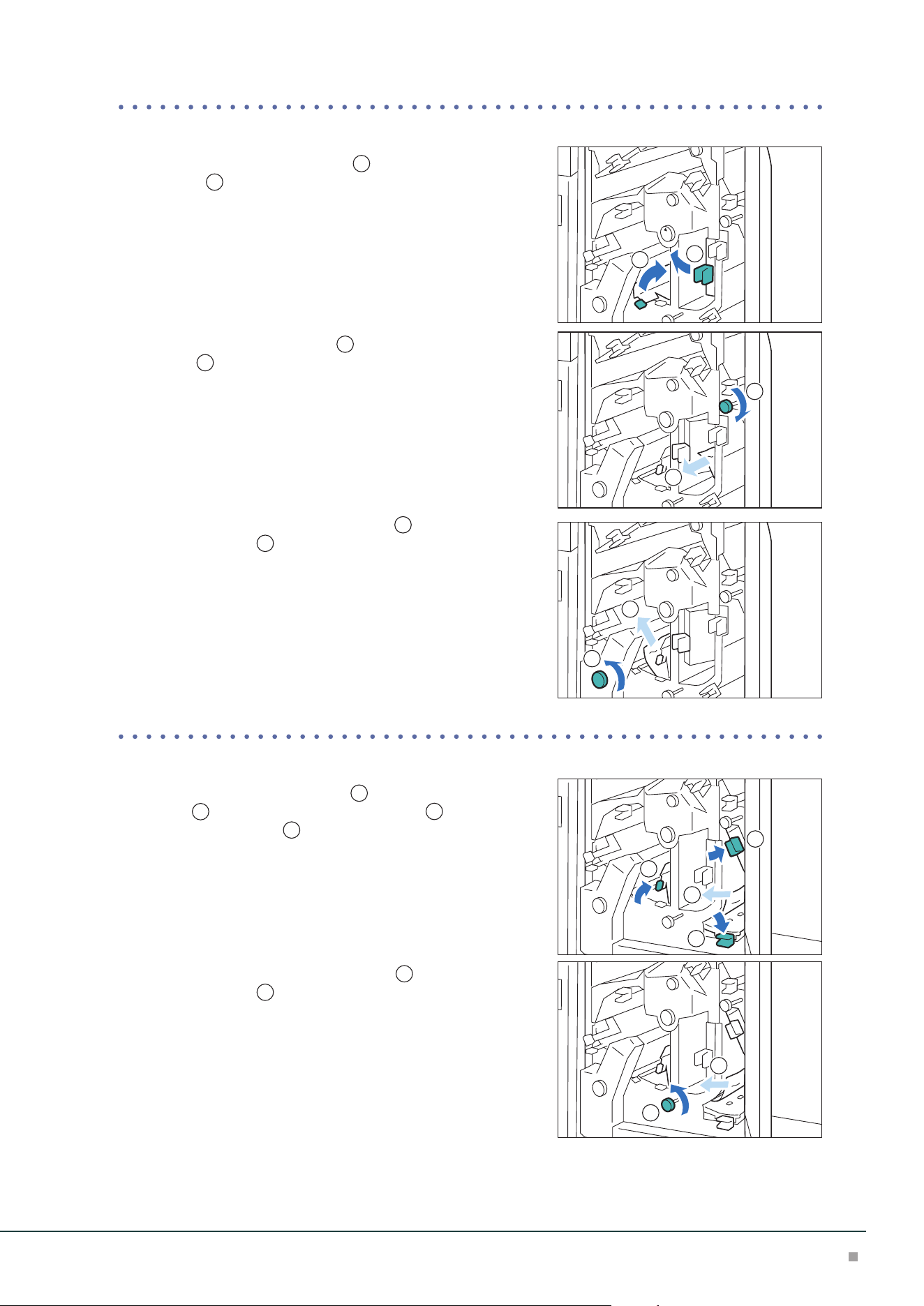
■When Indicator E3 is Turned on
(1) Open lever [1b] to the right (
1
), turn knob [1c] counter-
clockwise (
2
), and remove the jammed paper (
3
).
(2) Return lever [1b].
■When Indicator E4 is Turned on
(1) Open lever [1d] downward (
1
), turn knob [1c] counter-
clockwise (
2
), and remove the jammed paper (
3
).
(2) If you have difficulty in removing the papers, open the Up-
per Cover and remove the jammed paper.
(3) Return lever [1d].
3. Close the cover.
3
1
2
3
1
2

High Capacity Feeder
19
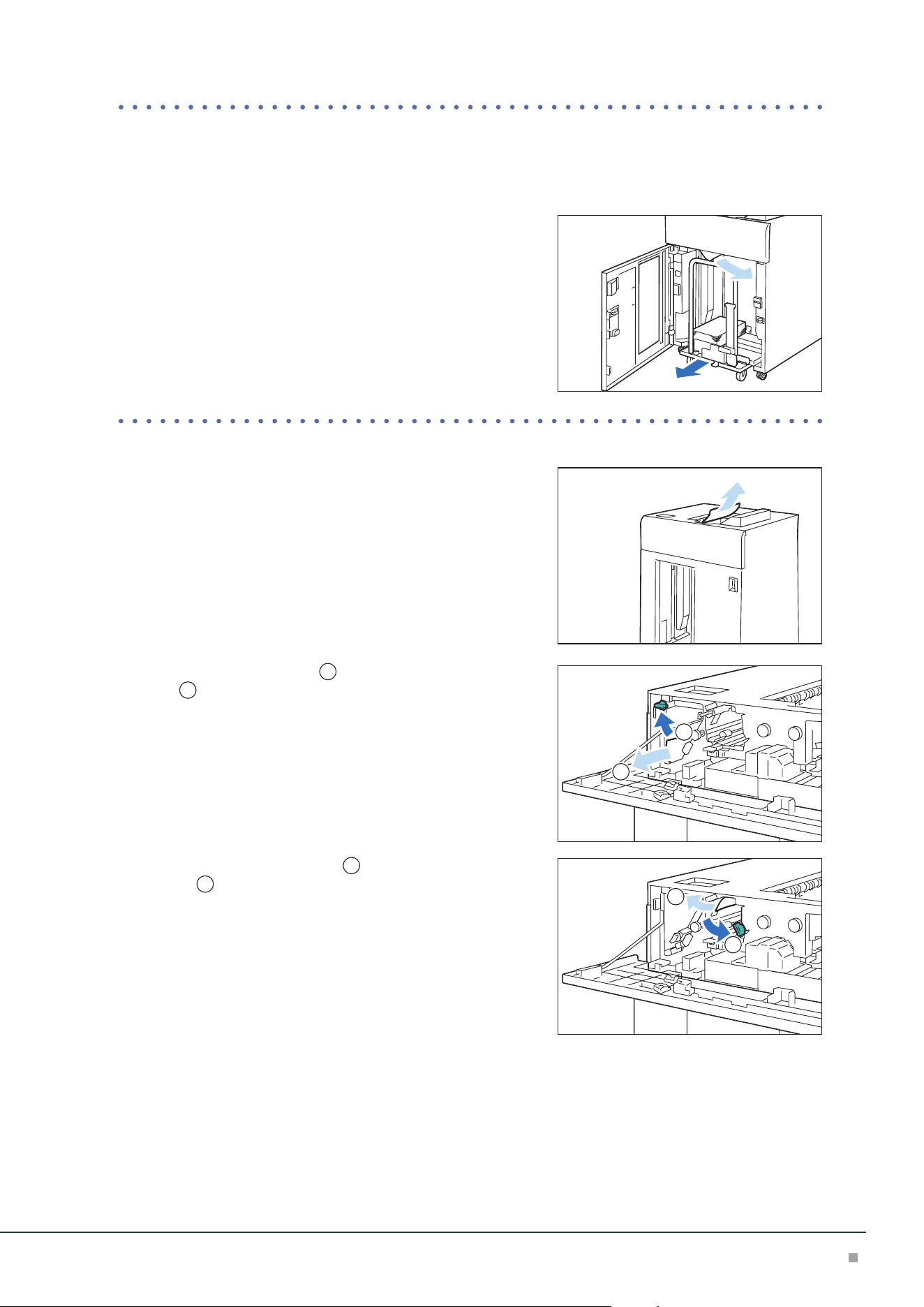
Paper Feeding Unit (Right Side at Continuous Feed Configuration)
■When Indicator E5 is Turned on
(1) Pull out the top cover toward you until it stops.
Confirm that no paper is jammed inside the Right Cover before pull-
ing it out.
(2) Open lever [2a] to the right (
1
), lever [2b] upward (
2
),
and remove the jammed paper (
3
).
(3) Return lever [2a] and [2b].
(4) Push the cover.
Note
3
1
2
Optional Units Manual
20
Cleaning Machine
• When you clean machine products, use the cleaning materials designated in every step.
• To wipe with a wet cloth, use the soft cloth tightly wrung out of water. If the parts are not com-
pletely dry, the machine may malfunction.
• Using commercially available non-woven dry type fabric is effective for cleaning paper dust.
Choose Non-woven fabric with soft and highly adsorptive that can easily wipe dirt and dust off.
Do not use nonwoven fabric containing organic solvents or a polishing agent.
• Do not use benzene, paint thinner, or other organic solvents. Doing so might damage paint or
coating on plastic parts.
After cleaning, be sure to close the cover. Leaving the cover open will not be able to continue to jobs.
Running Paper
Cleaning may temporarily cause a number of white dots to appear on the output. After cleaning,
feed paper through the machine to ensure effectiveness of the cleaning.
1. Create image data consisting C100% and M100% for SRA3 or A3 size.
2. Run a 2-sided job to print this image on about 20 sheets of paper.
Cleaning inside the Machine
No. Work Frequency Page
1
Cleaning High Capacity Trays Every week (When collected paper dust is found in the paper guide or
roller in the feeder cover)
p.20
2
Cleaning the Paper Feeding
Unit in the High Capacity Tray
Every week p.22
When you have finished cleaning, make sure the roller and the surface of paper path are free from foreign objects.
Cleaning High Capacity Trays
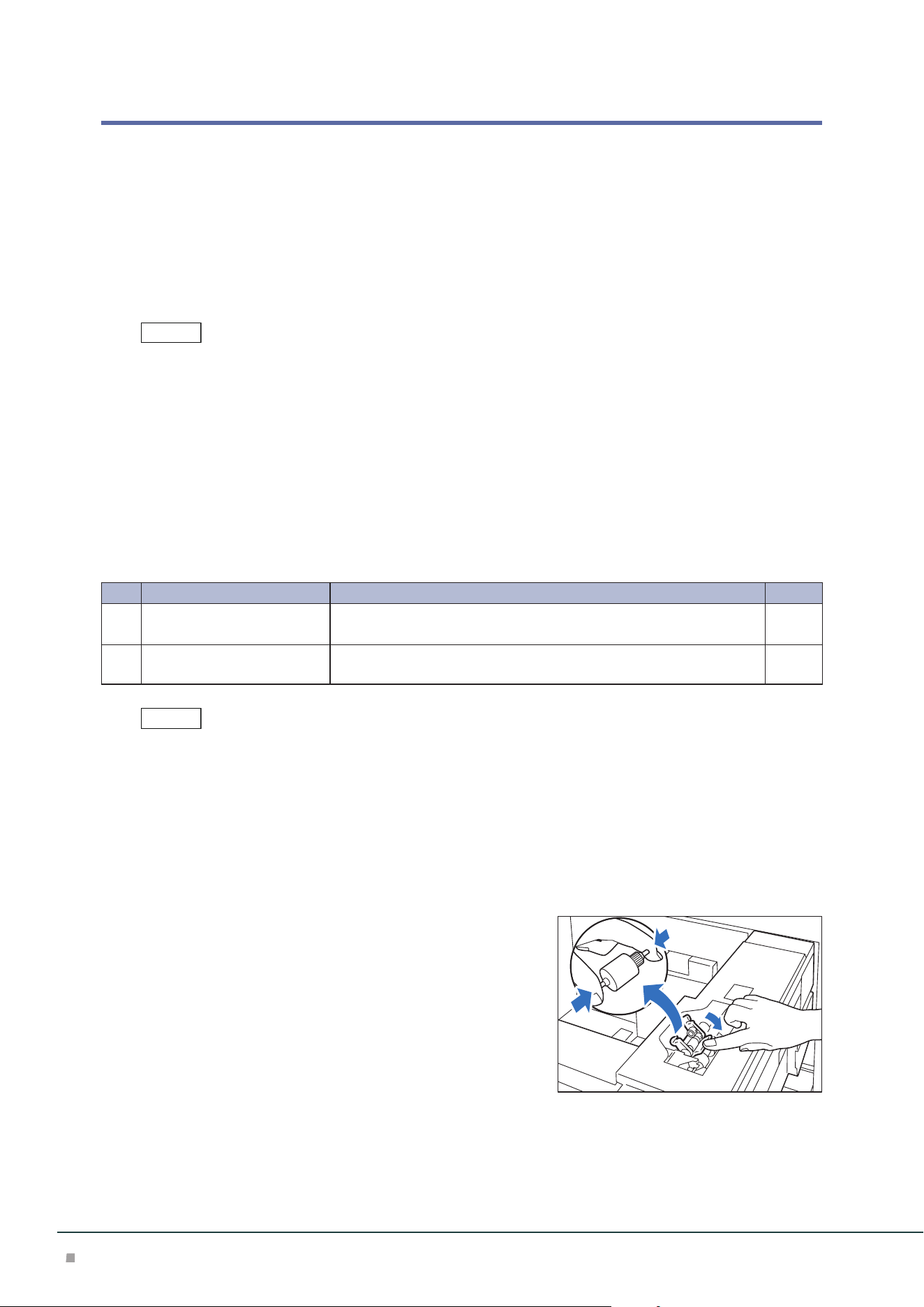
1. Pull out the Paper Tray toward you until it stops.
2. Clean the roller in the feeder cover located on the right side of the Paper Tray.
(1) Press down the roller 1 holder to the direction of the ar-
row, and remove roller 1 by picking up the both ends of its
pin with fingers.
Note
Note
High Capacity Feeder
21
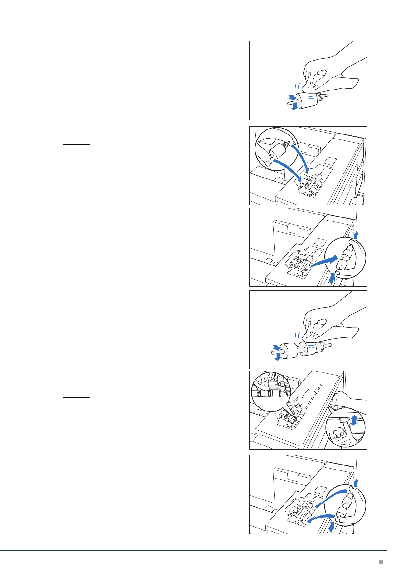
(2) Wipe the surface of roller 1 with the soft cloth tightly
wrung out of water.
(3) Reinstall roller 1.
Make sure that roller 1 is installed in the holder completely.
(4) Remove roller 2 by picking up the both ends of its pin.
(5) Wipe the surface of roller 2.
(6) Rotate the shaft of roller 3 with one hand, and wipe the
surface of roller 3 with the other hand.
Clean roller 3 without reinstalling roller 2.
(7) Reinstall roller 2.
3. Push in the Paper Tray.
4. Clean also the other Paper Tray with the steps 1 to 3.
Note
Note
Optional Units Manual
22
Cleaning the Paper Feeding Unit in the High Capacity Tray
• Do not press a roller during the cleaning, otherwise the roller may drop off.
• Non-woven dry type fabric can be used effectively for cleaning paper dust.
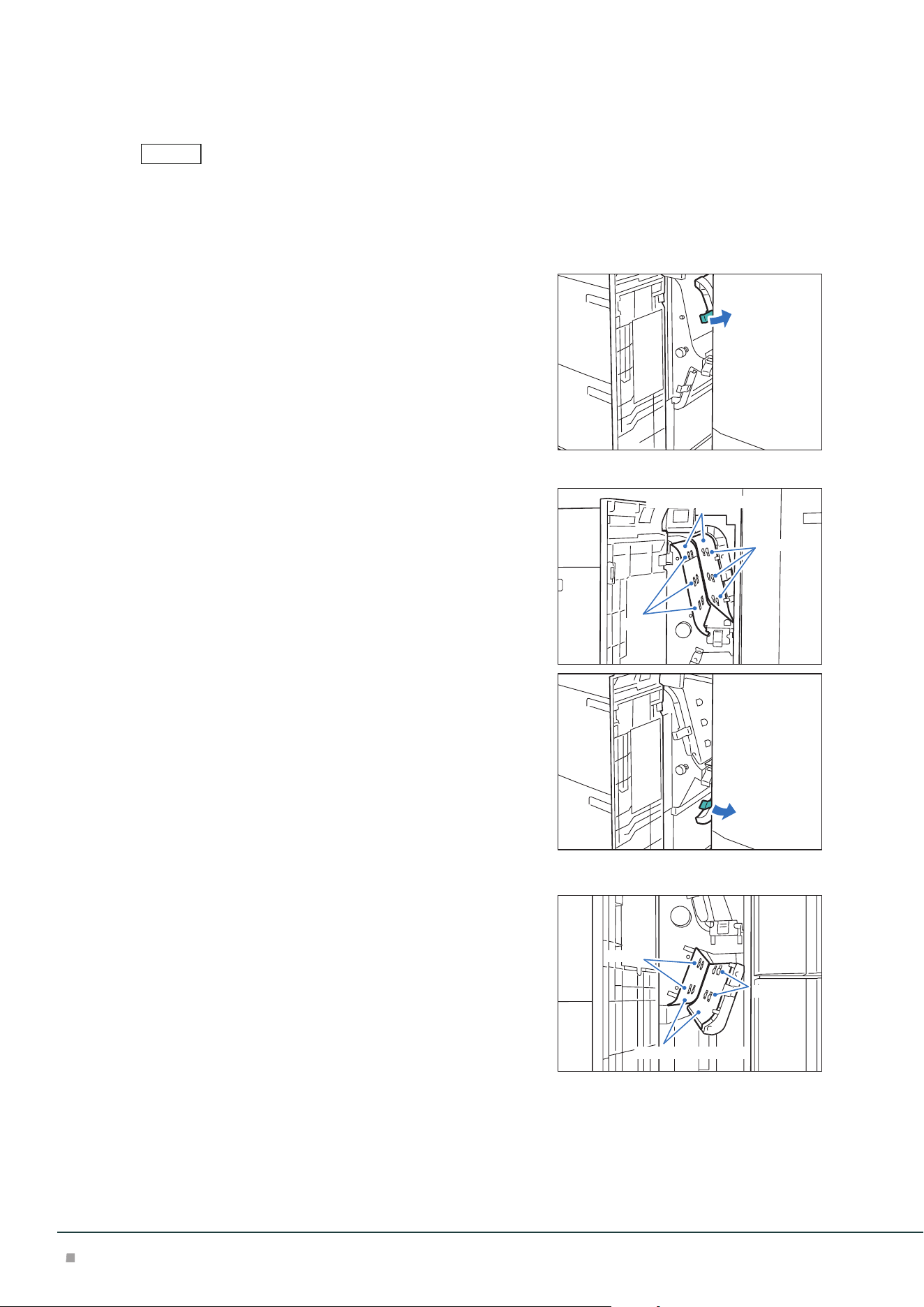
1. Open the Right Cover.
2. Open lever [1a] to the right.
3. Clean behind lever [1a].
(1) Wipe the roller surface with the soft cloth tightly wrung
out of water.
(2) Lightly wipe paper dust off on the surface of the paper
path.
4. Return lever [1a].
5. Open lever [1b] to the right.
6. Clean behind lever [1b].
(1) Wipe the roller surface with the soft cloth tightly wrung
out of water.
(2) Lightly wipe paper dust off on the surface of the paper
path.
7. Return lever [1b].
Note
Roller
Paper path surface
Roller
Roller
Paper path surface
Roller
High Capacity Feeder
23
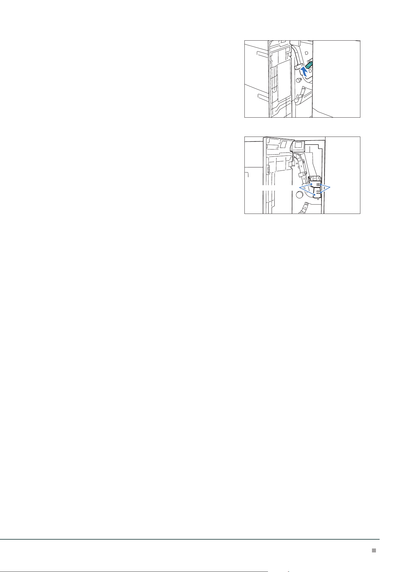
8. Open lever [1d] upward.
9. Clean behind lever [1d].
(1) Wipe the roller surface with the soft cloth tightly wrung
out of water.
(2) Lightly wipe paper dust off on the surface of the paper
path.
10. Return lever [1d].
11. Close the cover.
Roller
Paper path surface
Optional Units Manual
24
2 Air Suction Feeder
Device Components
7
21
56 4
3
No. Component Function
1
Bypass Tray (Paper Tray A1/A2-3) Load paper here.
2
Error Indicator When paper jam occurs, the indicator is turned on.
When the priority device indicator (top lamp) blinks, first of all perform
the paper jam operation.
3
Right Cover Open this cover to clear paper jams.
4
Remaining Volume Indicator When the Paper Tray is in operation, the top lamp is turned on.
You can check the remaining volume of paper with the 4 lamps (each
lamp indicates 25%) at the center.
When Paper Replenish Indicator is turned on, paper is empty.
5
Air Tray
Long Paper Tray
Paper Tray A1/A2-1 Load paper here.
6
Air Tray Paper Tray A1/A2-2
7
Ground Fault Interrupter A switch to automatically switch the machine off when a current leak-
age is detected.
The Caution Labels, Ground Fault Interrupter, Bypass Tray, Paper Jams and Cleaning the Paper Feeding Unit in the
High Capacity Tray are the same as the "1 High Capacity Feeder" (p.3).
Note
Air Suction Feeder
25
Main Specifications
Air Suction Feeder A3 / Air Suction Feeder A3 for Banner
Item
Description
Air Suction Feeder A3
Air Suction Feeder A3
+ Banner Unit for Air Suction Feeder
Paper size
*1
Standard size: Max SRA3 (320 x 450 mm), 12.6×19.2“ (320 x 488 mm), Min A6
Custom size:
98 x 148 mm to 330 x 488 mm
Custom size:
210 x 210 mm to 330 x 1200 mm
*2
(Upper tray),
98 x 148 mm to 330 x 488 mm (Lower tray)
Paper weight 52 to 400 g/m
2*3
Feeding Capacity /
Number of Tray
*4
2200 sheets x 2-tray + 250 sheets 900 sheets
*5
+ 2200 sheets + 250 sheets
Power supply AC 100-120 V +/- 10 %, 6 A, AC 220-240 V +/- 10 %, 4 A, 50/60 Hz common
Maximum power con-
sumption
880 W
Dimensions W 988 x D 762 x H 992 mm W 1580 x D 762 x H 992 mm
Weight
*6
194 kg 213 kg
*1: When setting main scanning 98 to 182 mm paper, Post Card Kit for Air Suction Feeder is required.
*2: Duplex Automatic Print supports paper size up to 330 x 729 mm.
*3: For long paper from 330 x 488 mm to 330 x 660 mm: 52 to 350 g/m
2
; for paper up to 330 x 729 mm: 52
to 300 g/m
2
; for paper up to 330 x 1200 mm: 52 to 256 g/m
2
. Duplex Automatic Print supports paper
weight up to 300 g/m
2
.
*4: 82 g/m2 paper
*5: 100 sheets for paper longer than 729 mm (82 g/m
2
).
*6: Including Multi Bypass Tray for Banner Print.
• Multi Bypass Tray for Banner Print is included.
• Air Suction Feeder A3 for Banner and Banner Unit for Air Suction Feeder are required as a set.
• Air Suction Feeder A3 for Banner can feed long paper only from the Upper tray.
Note
Optional Units Manual
26
Chained Air Suction Feeder A3 R / Chained Air Suction Feeder A3 L / Chained
Air Suction Feeder A3 L for Banner / Banner Unit for Air Suction Feeder
Item
Description
Chained Air Suction Feeder A3 R
+ Chained Air Suction Feeder A3 L
Chained Air Suction Feeder A3 R
+ Chained Air Suction Feeder A3 L for Banner
+ Banner Unit for Air Suction Feeder
Paper size
*1
Standard size: Max SRA3 (320 x 450 mm), 12.6×19.2“ (320 x 488 mm), Min A6
Custom size:
98 x 148 mm to 330 x 488 mm
Custom size: 98 x 148 mm to 330 x 488 mm,
210 x 210 mm to 330 x 1200 mm
*2
(Upper tray of the
left module)
Paper weight 52 to 400 g/m
2*3
Feeding Capacity /
Number of Tray
*4
2200 sheets x 2-tray x 2-connection
+ 250 sheets
2200 sheets x 2-tray + 900 sheets
*5
+ 2200 sheets + 250
sheets
Power supply AC 100-120 V +/- 10 %, 6 A, AC 220-240 V +/- 10 %, 4 A, 50/60 Hz common x 2 power
Maximum power
consumption
880 W x 2 power
Dimensions W 1980 x D 762 x H 992 mm W 2572 x D 762 x H 992 mm
Weight
*6
403 kg 420 kg
*1: When setting main scanning 98 to 182 mm paper, Post Card Kit for Air Suction Feeder is required.
*2: Duplex Automatic Print supports paper size up to 330 x 729 mm.
*3: For long paper from 330 x 488 mm to 330 x 660 mm: 52 to 350 g/m
2
; for paper up to 330 x 729 mm: 52
to 300 g/m
2
; for paper up to 330 x 1200 mm: 52 to 256 g/m
2
. Duplex Automatic Print supports paper
weight up to 300 g/m
2
.
*4: 82 g/m2 paper
*5: 100 sheets for paper longer than 729 mm (82 g/m
2
).
*6: Including Multi Bypass Tray for Banner Print.
• Multi Bypass Tray for Banner Print is included.
• Chained Air Suction Feeder A3 R and A3 L are required as a set.
• Chained Air Suction Feeder A3 R, Chained Air Suction Feeder A3 L for Banner and Banner Unit for Air Suction
Feeder are required as a set.
• Chained Air Suction Feeder A3 L for Banner can feed long paper only from the Upper tray.
Note
Air Suction Feeder
27
Loading Paper
Do not load paper above the maximum fill line. It may cause paper jams or machine malfunction.
• Position the guides correctly to match the paper size. Incorrectly positioned guides may cause misfeeding and
paper jams.
• In the event power is disconnected while the Paper Tray's bottom plate is rising, the plate may not move up
when the power is recovered. In this case, pull out the Paper Tray, make sure the plate is lowered, and then push
the Paper Tray into the machine slowly and firmly.
• When paper sheets are loaded or fed, the Paper Tray makes a sound of supplying air. This is caused by the Air
Assist function, and not an abnormal noise.
Loading to Air Tray
Images are printed on the face side of the loaded paper.
If the amount of the loaded paper is 100 sheets or less, the guides apply more pressure to the paper. It may cause
the paper to be distorted, leading to paper jams.
1. Pull out the Paper Tray toward you until it stops.
2. Remove any paper remaining in the Paper Tray.
3. Fan the paper well and load about 100 to 500 sheets
with the printed side facing up, and the paper edges
aligned in the direction of the arrow (
1
).
4. Pinch the long-side paper guide grip and adjust to
the correct paper size (
2
).
5. Load remaining sheets with the printed side facing
up, and align the paper edges in the direction of the
arrow (
1
).
6. Adjust the short-side paper guide to the correct paper
size (
2
).
To leave a space, pinch the paper guide grip to move.
To narrow, push the paper guide to move.
7. Push in the Paper Tray.
Important
Note
Note
1
2
1
2
Optional Units Manual
28
Postcard Setting
Attach Postcard Kit for Air Suction Feeder to the Paper Tray to load paper with the width of 98 to
181.9 mm.
1. Pull out the Paper Tray toward you until it stops.
2. Remove any paper remaining in the Paper Tray.
3. Remove the shutters.
(1) Fold the shutters.
(2) Hold the shutters up and remove them.
4. Insert the guide A into the slit on the interior side (
1
) and the slit on the bottom (
2
), and then tighten the
screw of the guide to fix (
3
).
5. Insert the guide B into the slit on your side (
1
) and
the slit on the bottom (
2
), and then tighten the
screw of the guide to fix (
3
).
If the screw is not tighten well, it may hit on the transport device to
result in break.
6. Load about 100 to 500 sheets of paper with the print-
ed side facing up, and align the paper edges in the
direction of the arrow (
1
).
• Be sure to set them in short edge feed.
• The right side short edge of the set postcard will be the front edge.
7. Pinch the long-side paper guide grip and adjust to
the correct paper size (
2
).
1
2
1
3
1
2
Important
3
1
2
Note
1
2
Air Suction Feeder
29
8. Load remaining sheets with the printed side facing
up, and align the paper edges in the direction of the
arrow (
1
).
9. Adjust the short-side paper guide to the correct pa-
per size (
2
).
To leave a space, pinch the paper guide grip to move.
To narrow, push the paper guide to move.
10. Push in the Paper Tray.
11. To remove the Kit from the Paper Tray, loosen the screw completely and then remove the
Kit.
12. To mount the shutters, place the shutters on the origi-
nal positions and expand them.
Hang the edges of the shutters on the protrudes. Confirm
that they are firmly fixed.
Align the △ marks so that the shutters can be mounted in the cor-
rect orientation. The △ mark on the guide at the top edge of paper
is not viewed, and the △ mark on the guide at the bottom edge of
paper is viewed in the correct state.
Special Media Setting
■Hole Punched Paper
Orientation: Place the holes of paper on the right side when you face the front side of machine.
■Precut Tab
Orientation: Place the tabs of paper on the left side when
you face the front side of machine.
After loading paper, mount the tab guide (for A5 or A4)
on the short-side paper guide.
Make sure that the rear edges (tab parts) of the precut tab fit the
notch of the tab guide.
1
2
Note
Note
A4
A5
Optional Units Manual
30
Loading to Long Paper Tray
Images are printed on the face side of the loaded paper.
• If the amount of the loaded paper is 100 sheets or less (10 to 20 sheets for 864 mm or more paper), the guides
apply more pressure to the paper. It may cause the paper to be distorted, leading to paper jams.
• Postcard Kit for Air Suction Feeder cannot be used with the long paper tray.
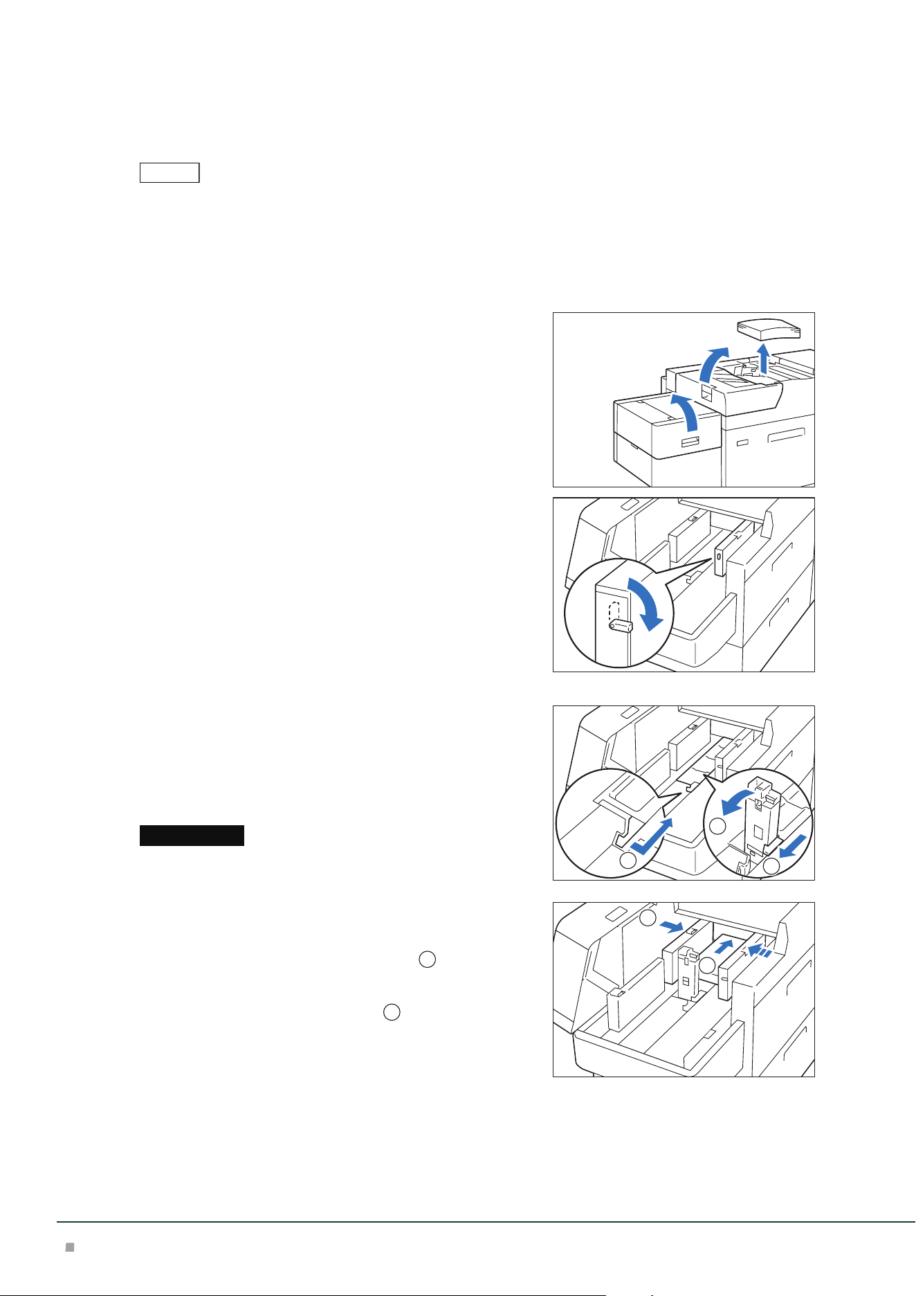
488 mm or Less Paper
1. Remove the paper loaded on the Bypass Tray.
2. Open two covers.
3. Turn the lever on the left of the long-side paper guide
downward.
4. Remove any paper remaining in the Tray.
5. If the short-side paper guide is stored, pull the short-side guide up.
(1) Open the shutter while pinching the lever.
(2) Hold the paper guide and pull it up. Pull the paper guide
until it clicks to be fixed.
(3) Close the shutter while pinching the lever.
Do not hold the paper guide grip to pull up. The paper guide grip
may break.
6. Fan the paper well and load about 100 to 500 sheets
with the printed side facing up, and the paper edges
aligned in the direction of the arrow (
1
).
7. Pinch the right side long-side paper guide grip and
adjust to the correct paper size (
2
).
Note
Important
3
1
2
1
2
Air Suction Feeder
31
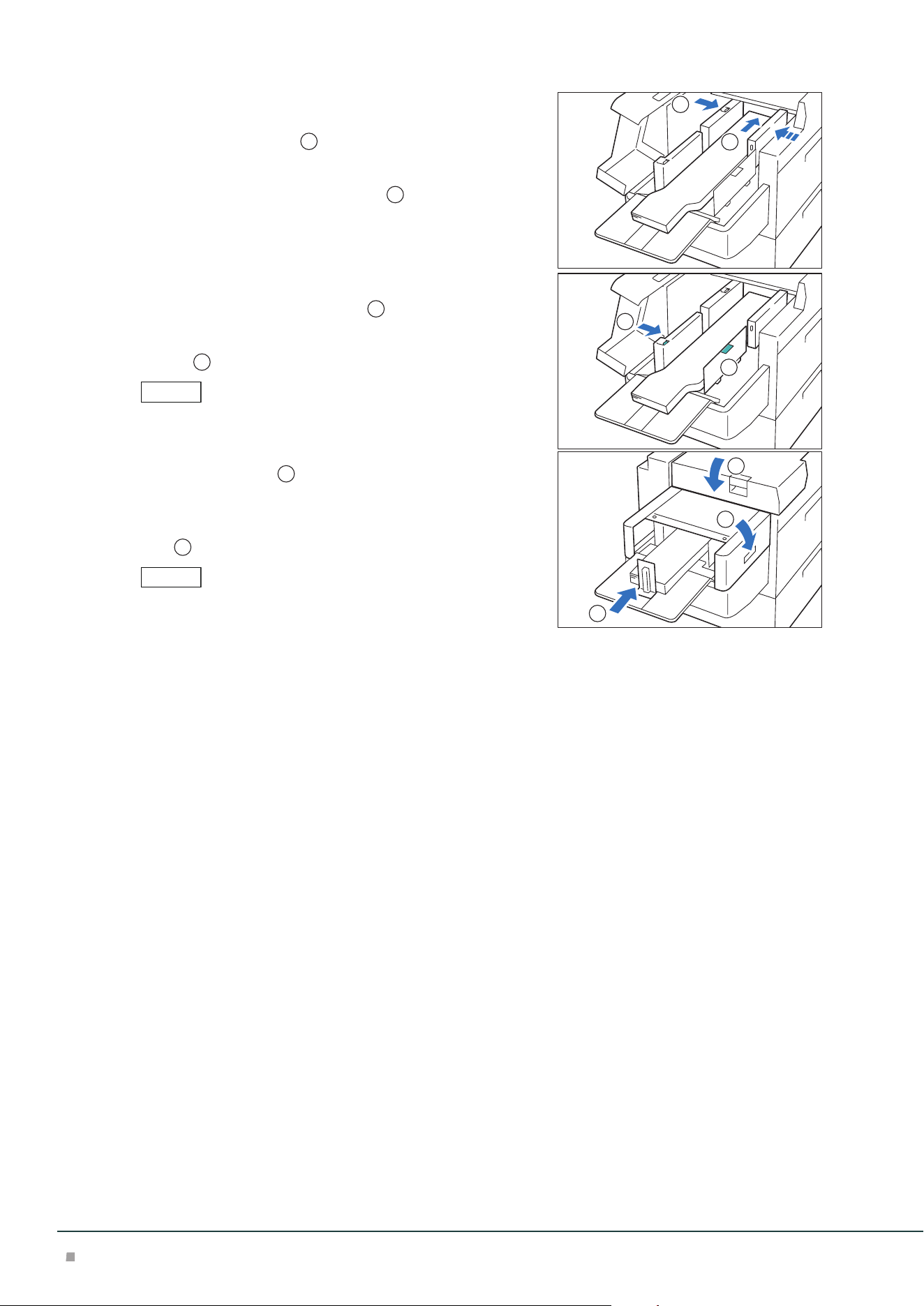
8. Load remaining sheets with the printed side facing
up, and align the paper edges in the direction of the
arrow (
1
).
9. Adjust the short-side paper guide to the correct pa-
per size (
2
).
To leave a space, pinch the paper guide grip to move.
To narrow, push the paper guide to move.
10. Close two covers.
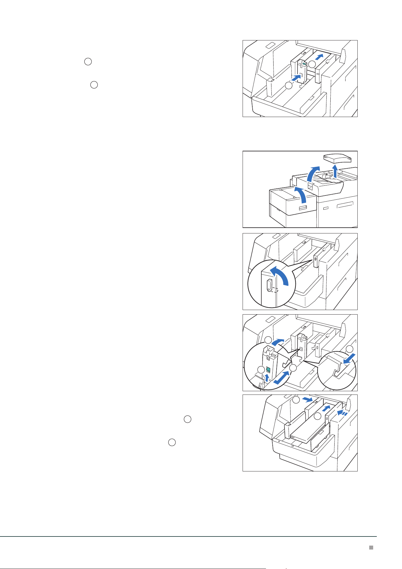
488.1 to 864 mm Paper
1. Remove the paper loaded on the Bypass Tray.
2. Open two covers.
3. Turn the lever on the left of the long-side paper guide
upward.
4. Remove any paper remaining in the Tray.
5. If the short-side paper guide is standing, store it.
(1) Open the shutter while pinching the lever.
(2) Lay the paper guide down while holding the release lever.
(3) Close the shutter while pinching the lever.
6. Fan the paper well and load about 100 sheets with
the printed side facing up, and the paper edges
aligned in the direction of the arrow (
1
).
7. Pinch the right side long-side paper guide grip and
adjust to the correct paper size (
2
).
1
2
3
1
2
2
1
2
Optional Units Manual
32
8. Pinch the left side long-side paper guide grip and ad-
just to the correct paper size (
1
).
9. Place the bottom edge paper guide to fit the loaded
paper (
2
).
The bottom edge guide is removable. Install it in the direction such
that the metal surface touches paper.
10. Load remaining sheets with the printed side facing
up, and align the paper edges in the direction of the
arrow.
11. Place the rear edge paper guide to fit the loaded pa-
per.
The rear edge guide is removable. Install it in the direction such that
the metal surface touches paper.
12. Close two covers.
864.1 mm or More Paper
Up to 100 sheets can be loaded.
1. Unfasten the screws and remove the left side cover.
2. Remove the paper loaded on the Bypass Tray.
3. Open two covers.
Note
1
2
Note
Air Suction Feeder
33
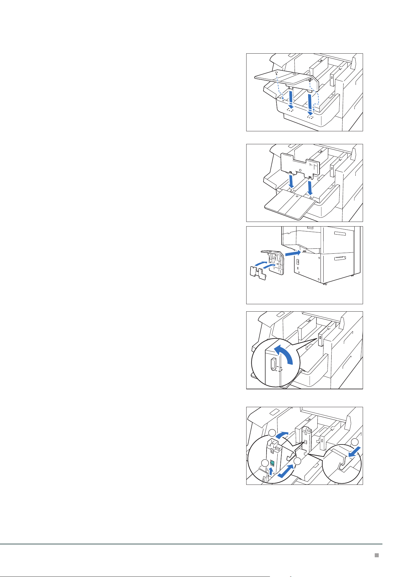
4. Attach the extension tray and the supporting plate.
(1) Insert the extension tray and tighten the screws to fix.
(2) Insert the supporting plate.
When not in use, hang the parts on the holder of the lower
part.
5. Turn the lever on the left of the long-side paper guide
upward.
6. Remove any paper remaining in the Tray.
7. If the short-side paper guide is standing, store it.
(1) Open the shutter while pinching the lever.
(2) Lay the paper guide down while holding the release lever.
(3) Close the shutter while pinching the lever.
3
1
2
2
Optional Units Manual
34
8. Fan the paper well and load sheets with the printed
side facing up, and the paper edges aligned in the di-
rection of the arrow (
1
).
9. Pinch the right side long-side paper guide grip and
adjust to the correct paper size (
2
).
10. Pinch the left side long-side paper guide grip and ad-
just to the correct paper size (
1
).
11. Place the bottom edge paper guide to fit the loaded
paper (
2
).
The bottom edge guide is removable. Install it in the direction such
that the metal surface touches paper.
12. Close two covers (
1
) and wait until the bottom
plate rises.
13. Place the rear edge paper guide to fit the loaded pa-
per (
2
).
The rear edge guide is removable. Install it in the direction such that
the metal surface touches paper.
1
2
Note
1
2
Note
1
2
1
Interface Decurler Module
35
3
Interface Decurler Module
Device Components
3
2
1
No. Component Function
1
Error Indicator When paper jam occurs, the indicator is turned on.
When the indicator blinks, first of all perform the paper jam operation.
2
Curl correction button Press the button to correct paper curl. This curl correction function can be used
during printing.
3
Cover Open this cover to clear paper jams.
Main Specifications
Item Description
Power supply AC 100-240 V +/- 10 %, 2.5 A (100 V) / 1 A (240 V), 50/60 Hz common
Maximum power consumption 250 W
Dimensions W 340 x D 725 x H 992 mm
Weight 40 kg
Interface Decurler Module is necessary for connecting High Capacity Stacker, Finisher, or Finisher with Booklet
Maker, to the printer.
Note
Optional Units Manual
36
Curl Correction
The curl correction button is used to correct paper curl caused by heat and/or pressure.
The curl correction button can be operated regardless of the machine state when the machine is
ON.
• This curl correction function can be used during printing. Fine correction according to the paper properties can
be made from Printer User Interface.
• Since staples are likely to be affected by curl, make sure to perform curl correction by checking the curl direction
of output paper.
• When correction is performed while the machine is in operation, it is applied to the paper output immediately
after the button is pressed.
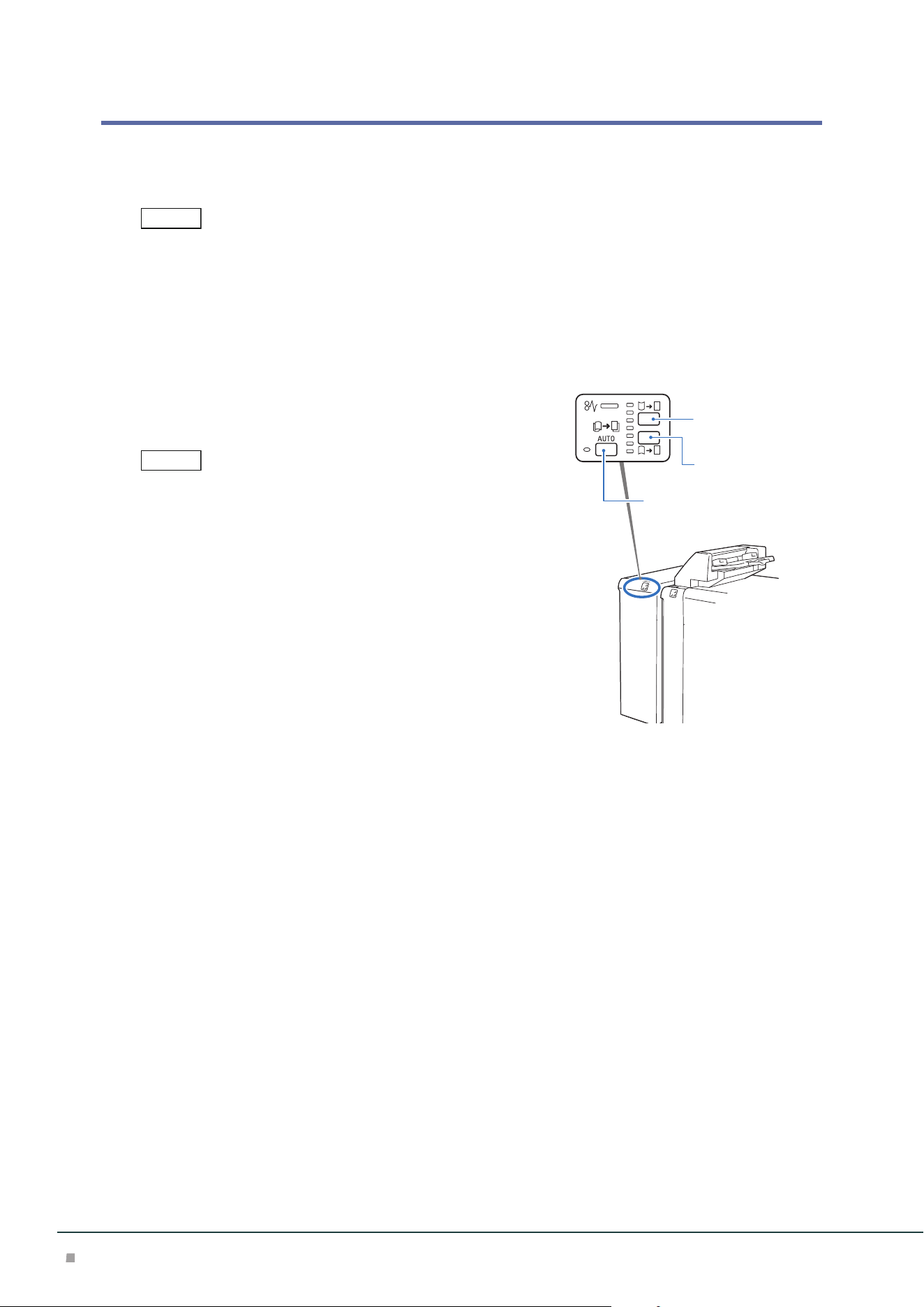
1. Check the curl direction of paper.
2. Confirm that the curl correction indicator is lit, and
then press the button.
• When paper is fed in the [AUTO] mode, the indicator showing the
present direction and intensity of curl correction turns on only for
a brief moment. When manually applying the curl correction,
make adjustments while using this indicator lighting as a guide.
• After applying the curl correction by upward curl correction button
or downward curl correction button, when feeding thick paper,
embossed paper, or OHP film, the [AUTO] is entered automatical-
ly, and the curl correction is applied using standard correction val-
ue.
You can also change to a setting that the mode does not change to
[AUTO] mode even when using these paper types. Please contact
your local dealer for more information.
Note
Note
Upward curl
correction button
Downward curl
correction button
<AUTO> button
Interface Decurler Module
37
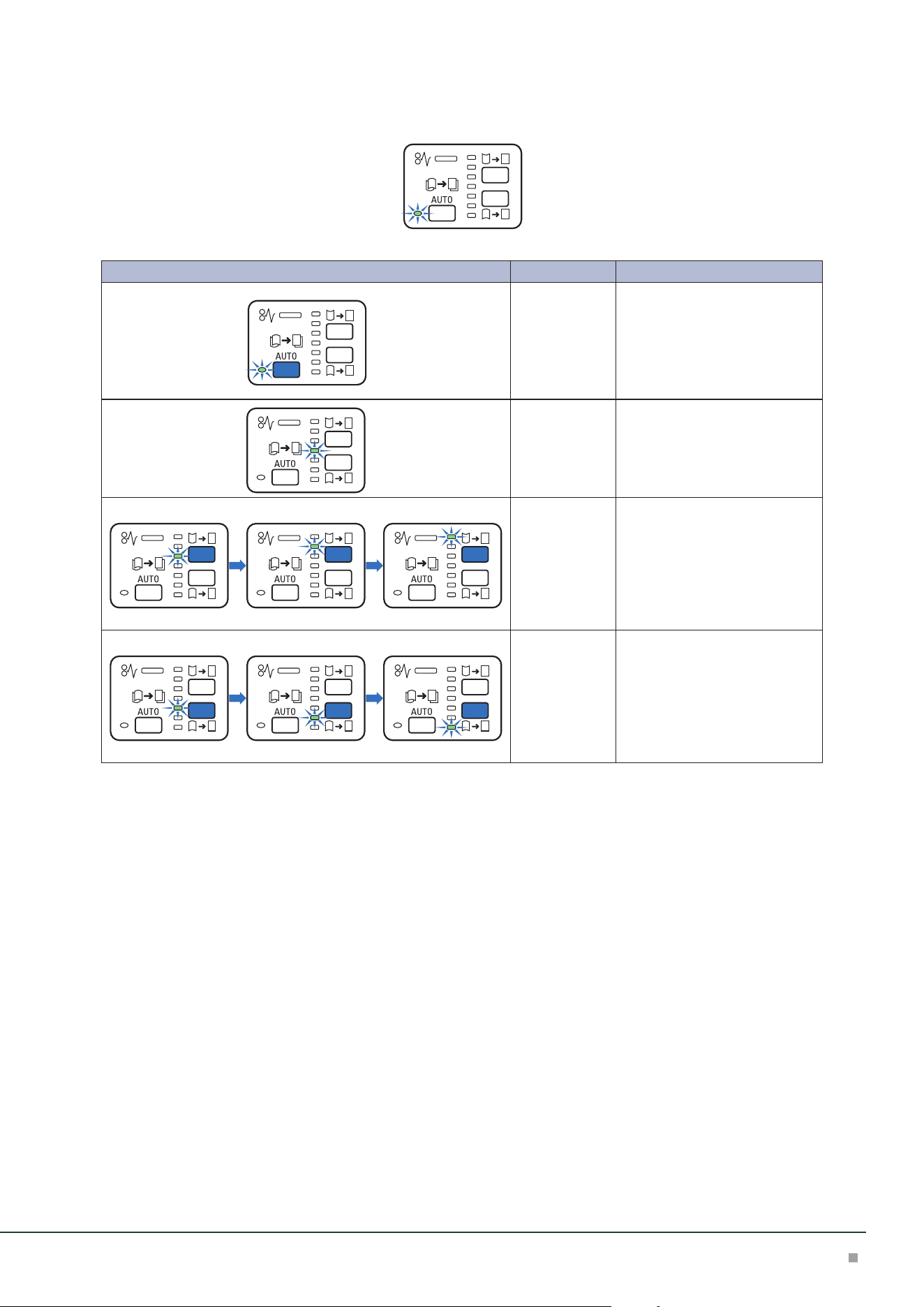
Operations and Functions of Curl Correction
Press the AUTO button to enter the [AUTO] mode.
Indicator Mode Function
AUTO Curl correction is automatically
performed.
It is recommended to use this
mode basically.
Optimum curl correction is per-
formed according to the paper
size and output direction.
OFF Curl correction is not per-
formed.
Upward curl Upward curl correction is per-
formed when output paper is
curled upward.
Every time the upward curl cor-
rection button is pressed, the
degree of correction is changed.
The higher the indicator's posi-
tion, the stronger the correction.
Downward curl Downward curl correction is
performed when output paper
is curled downward.
Every time the downward curl
correction button is pressed, the
degree of correction is changed.
The lower the indicator's posi-
tion, the stronger the correction.
Optional Units Manual
38
Paper Jams
The error indicator at the top of the machine is turned on. When the indicator blinks, first of all perform the paper
jam operation.
If paper is jammed, the machine stops and an alarm sounds. Follow the instructions displayed on
the screen to remove the jammed paper.
Gently remove the paper being careful not to tear it. If paper is torn while it is being removed from
the machine, remove all the torn pieces making sure that none remain inside the machine.
When you have finished clearing the paper jam, printing is resumed from the state before the pa-
per jam occurred.
Clear the paper jams while the machine is on.
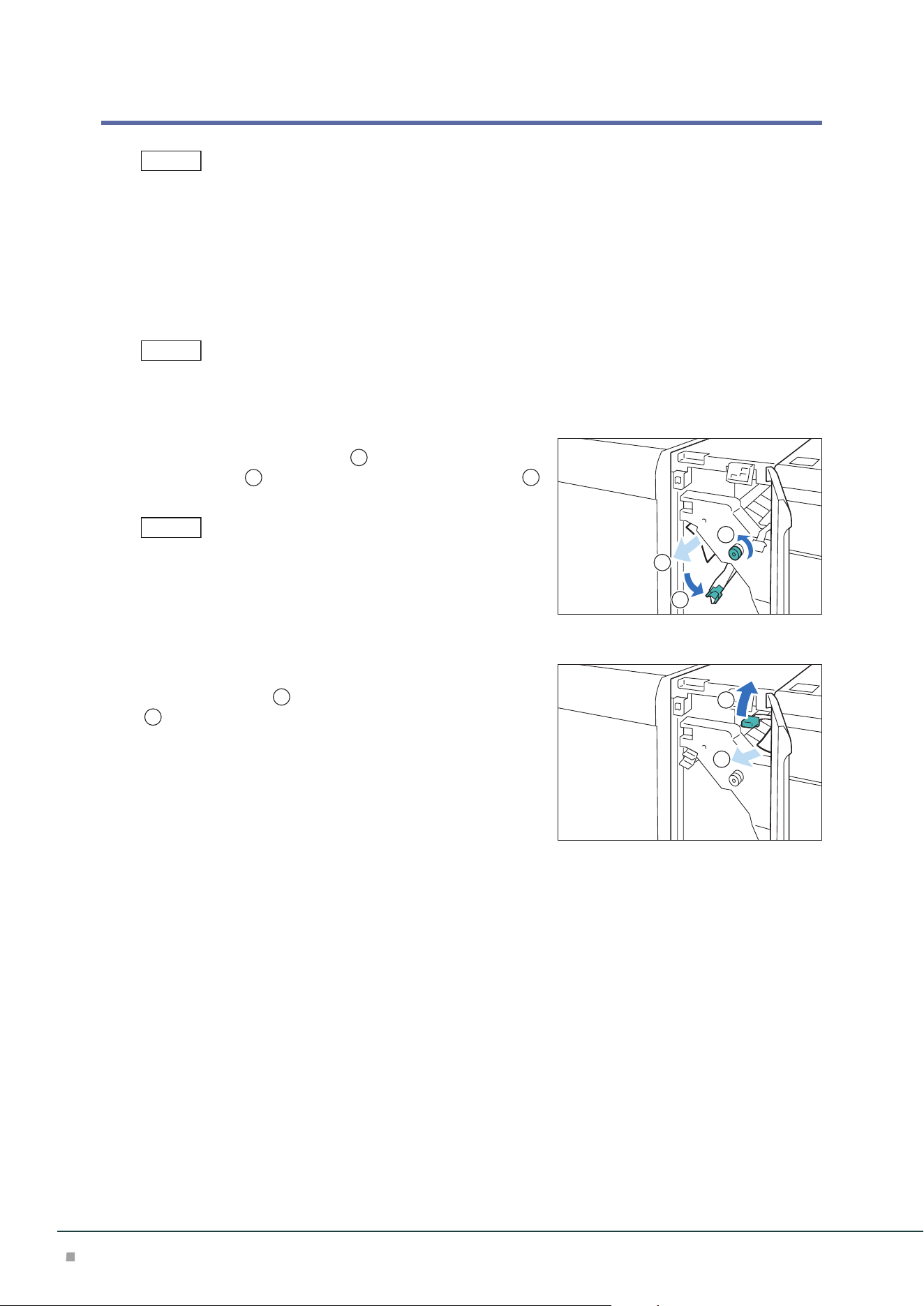
1. Open the Cover.
2. Open lever [1a] downward (
1
), turn knob [1b] coun-
terclockwise (
2
), and remove the jammed paper (
3
).
• Make sure to turn knob 10 times or more.
• When removing paper, make sure to remove it as pulling it out
slowly.
• Jammed paper may be hidden at the upper section.
3. Return lever [1a].
4. If you have difficulty in removing the papers, open le-
ver [1c] upward (
1
) and remove the jammed paper
(
2
).
5. Return lever [1c].
6. Close the cover.
Note
Note
Note
1
2
3
2
1
Inserter
39
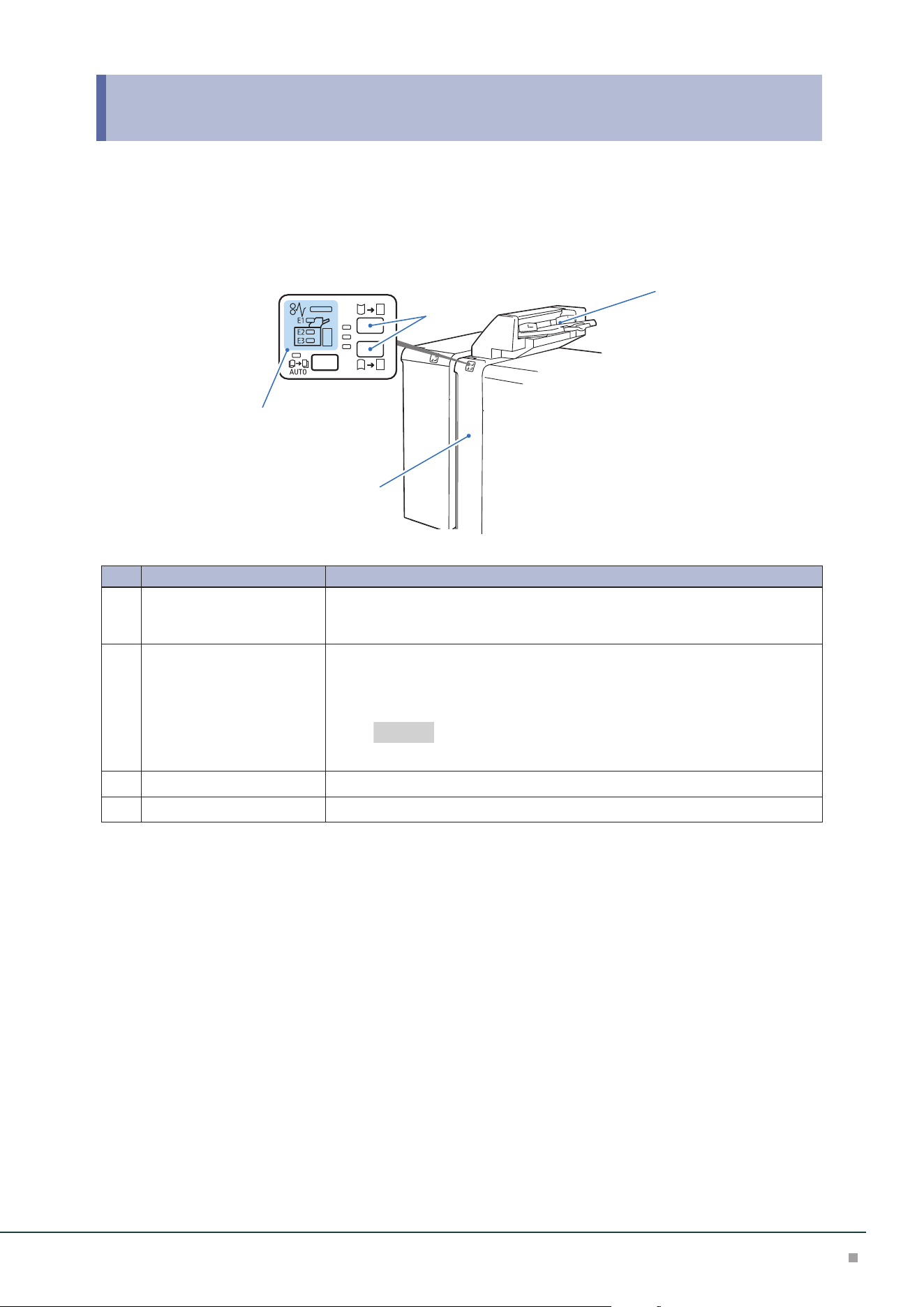
4 Inserter
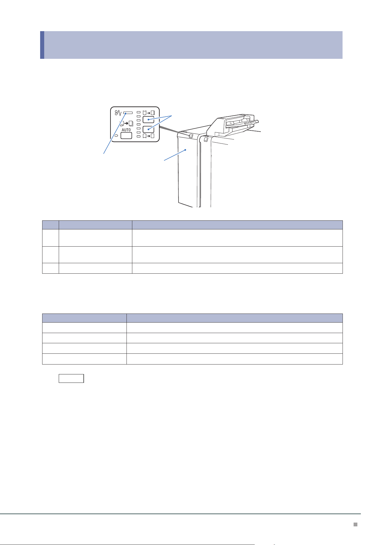
Device Components
4
3
2
1
No. Component Function
1
Error Indicator When paper jam occurs, the indicator is turned on.
When the priority device indicator (top lamp) blinks, first of all perform the paper
jam operation.
2
Curl correction button Use this button when curl cannot be corrected even if the highest correction (or
lowest correction) of Interface Decurler Module is performed. The correction
method is the same as the Interface Decurler Module. The 3 correction levels are
available: OFF, upward, and downward.
"Curl Correction" (p.36)
3
Inserter Tray (Paper Tray T1) Load paper to be used as an interleaf or cover.
4
Cover Open this cover to clear paper jams.
Refer

Optional Units Manual
40
Main Specifications
Item
Description
Paper size Standard size:
Max SRA3 (320 x 450 mm), 12.6×19.2“ (320 x 488 mm), Min A5
Custom size:
182 x 148 mm to 330 x 488 mm
Paper weight 52 to 350 g/m
2
Paper capacity
*1
250 sheets
Power supply Supplied from Interface Decurler Module
Dimensions W 700
*2
x D 725 x H 1235 mm
Weight 37 kg
*1: 82 g/m2 paper
*2: The width of the paper transfer part only when connected to the device is 165 mm.
High Capacity Stacker, Finisher, or Finisher with Booklet Maker is required.
Note
Inserter
41
Loading Paper
Load paper (blank paper or printed paper) to be used as an interleaf or cover.
Inserter Tray is used to load paper used as an interleaf or cover, and print cannot be performed.
• After removing all the paper from the Tray, and then load the paper again together with the paper you want to
add.
• Saddle stitch / single fold is available only when the same paper size is used as with the body (paper output from
the printer main unit).
• Load paper first before starting the job.
1. Fan the paper well and insert it along the paper guide
all the way until it touches the back.
Do not load paper above the maximum fill line. It may cause paper
jams or machine malfunction.
2. Adjust the paper guide to the size of loaded paper.
If the paper guide width is narrower or wider than the paper, it may
cause paper jams.
Special Media Setting
■Hole Punched Paper
Orientation: Place the holes of paper on the right side when you face the front side of machine.
■Precut Tab
Orientation: Place the tabs of paper on the left side when you face the front side of machine.
Purge Function
The printer stops printing when paper runs out. When this happens, sheets of paper being fed are
delivered to the optional unit's output tray.
• Do not reuse the sheets ejected by the Purge function, as this may cause paper jams.
• You can also set so that purging does not occur when paper runs out.
Note
Important
Note
Note
Optional Units Manual
42
Paper Jams
The error indicator at the top of the machine is turned on. When the priority device indicator (top lamp) blinks,
first of all perform the paper jam operation.
If paper is jammed, the machine stops and an alarm sounds. Follow the instructions displayed on
the screen to remove the jammed paper.
Gently remove the paper being careful not to tear it. If paper is torn while it is being removed from
the machine, remove all the torn pieces making sure that none remain inside the machine.
When you have finished clearing the paper jam, printing is resumed from the state before the pa-
per jam occurred.
Clear the paper jams while the machine is on.
1. Remove the jammed paper.
When Indicator E1 is Turned on .................................................................................................p.42
When Indicator E2 is Turned on .................................................................................................p.42
When Indicator E3 is Turned on .................................................................................................p.43
■When Indicator E1 is Turned on
(1) Open the Upper Cover and remove all the jammed papers
and papers loaded on the tray.
(2) Close the cover.
(3) Align the 4 corners of the removed papers and load them
again.
■When Indicator E2 is Turned on
(1) Open the Cover.
(2) Open lever [1a] upward (
1
), turn knob [1b] counter-
clockwise (
2
), and remove the jammed paper (
3
).
(3) Return lever [1a].
Note
Note
3
1
2
Inserter
43
(4) If you have difficulty in removing the papers, open lever
[1c] to the right (
1
), turn knob [1b] counterclockwise
(
2
), and remove the jammed paper (
3
).
(5) Return lever [1c].
(6) Close the cover.
■When Indicator E3 is Turned on
(1) Open the Cover.
(2) Open lever [1d] downward (
1
), turn knob [1e] counter-
clockwise (
2
), and remove the jammed paper (
3
).
Jammed paper may be hidden at the upper section.
(3) Return lever [1d].
(4) If you have difficulty in removing the papers, open lever
[1a] upward (
1
), turn knob [1e] clockwise (
2
), and re-
move the jammed paper (
3
).
(5) Return lever [1a].
(6) Close the cover.
2. Check the curl direction of the jammed paper and correct the curl.
"Curl Correction" (p.36)
1
2
3
Note
2
3
1
1
2
3
Refer
Optional Units Manual
44
5 Static Eliminator
Device Components
3
1
2
No. Component Function
1
Error Indicator When paper jam occurs, the indicator is turned on.
When the indicator blinks, first of all perform the paper jam operation.
2
Applied voltage count Set applied voltage according to the media to feed.
Set “00” for media that do not need static electricity discharge.
If media are fed as applied voltage is set, it may cause a failure according to the
media.
3
Cover Open this cover to clear paper jams.
Main Specifications
Item Description
Power supply AC 100-127 V +/- 10 %, 3A, AC 200-240 V +/- 10 %, 1.8 A, 50/60 Hz common
Maximum power consumption 300 W
Dimensions W 232 x D 725 x H 992 mm
Weight 37 kg
Interface Decurler Module is required.
Important
Note

Static Eliminator
45
Setting Voltage
1. Enter a value according to the media to use.
Humidity Media Standard value Upper limit
Low humidity (15% or less)
PET 65 to 90
Surface layer: Resin
Inner layer: Paper
65 to 99
Normal humidity (16 to 55%)
PET 50 to 70
Surface layer: Resin
Inner layer: Paper
60 to 99
High humidity (56% or more)
PET 40 to 60
Surface layer: Resin
Inner layer: Paper
65 to 99
• Static electricity may not be discharged sufficiently according to the media.
• Applied voltage of multiple-layer media that consist of resin and paper is higher than that of single-layer media.
• Adherence may remain in the case of multi-layer media.
2. Make test prints (about 3 to 5 prints) and check the degree of adherence.
3. When adherence occurs, change the value by +1 (when the degree of adherence is small)
to +10 (when the degree of adherence is large) as checking the degree of adherence.
Do not enter a value exceeding the upper limit. Do not increase the value by +11 or more at once.
If the value is increased too much, it also causes adherence of media.
Note
Note
Optional Units Manual
46
Paper Jams
The error indicator at the top of the machine is turned on. When the indicator blinks, first of all perform the paper
jam operation.
If paper is jammed, the machine stops and an alarm sounds. Follow the instructions displayed on
the screen to remove the jammed paper.
Gently remove the paper being careful not to tear it. If paper is torn while it is being removed from
the machine, remove all the torn pieces making sure that none remain inside the machine.
When you have finished clearing the paper jam, printing is resumed from the state before the pa-
per jam occurred.
Clear the paper jams while the machine is on.
1. Open the Cover.
2. Open lever [1a] downward (
1
), turn knob [1b]
clockwise (
2
), and remove the jammed paper (
3
).
3. Return lever [1a].
4. Close the cover.
Note
Note
1
2
3
High Capacity Stacker
47
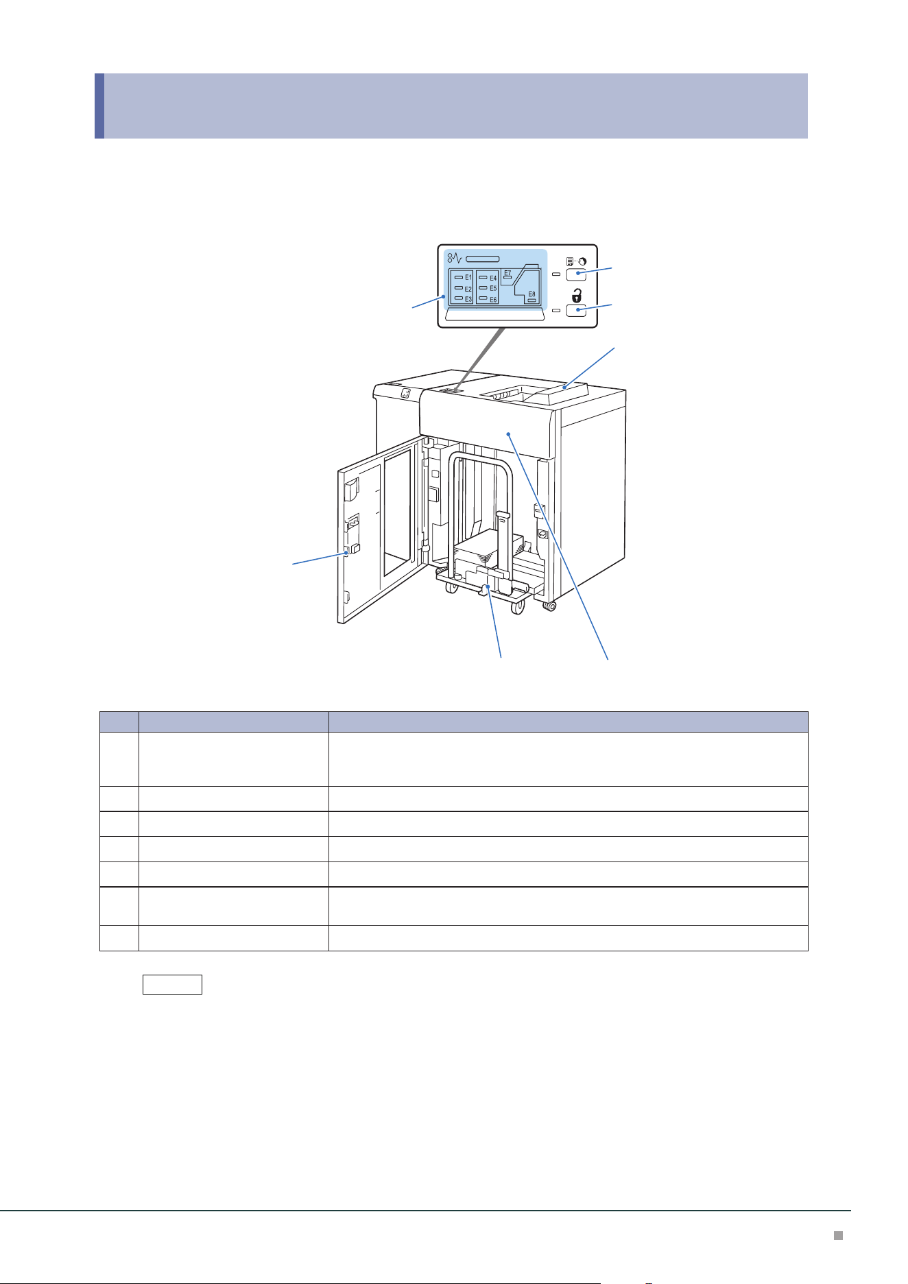
6 High Capacity Stacker
Device Components
6
4
5
7
2
3
1
No. Component Function
1
Error Indicator When paper jam occurs, the indicator is turned on.
When the priority device indicator (top lamp) blinks, first of all perform the pa-
per jam operation.
2
Sample button Press the button to output a sample to the Top Output Tray.
3
Paper eject button Press the button to stop printing and take out outputs.
4
Top Output Tray Outputs are delivered here. A sample is delivered here.
5
Front Upper Cover Open this cover to clear paper jams.
6
Stacker Tray (Stacker cart) When the paper eject button is pressed, paper is moved to the stacker cart and
ejected.
7
Lower Front Cover Open this cover to take out outputs.
The installed first and second High Capacity Stackers are the same one.
Note
Optional Units Manual
48
Main Specifications
Item Description
Paper capacity
*1
Output Tray 500 sheets
*2
High Capacity
Stacker – Stacker
Cart
5000 sheets
Paper size Output Tray Standard size:
Max SRA3 (320 x 450 mm), 12.6×19.2“ (320 x 488 mm), Min A6
Custom size:
98 x 148 mm to 330 x 488 mm
*3
High Capacity
Stacker – Stacker
Cart
Standard size:
Max SRA3 (320 x 450 mm), 12.6×19.2“ (320 x 488 mm), Min JIS B5
Custom size:
203 x 182 mm to 330 x 488 mm
Paper weight Output Tray 52 to 400 g/m
2
High Capacity
Stacker – Stacker
Cart
52 to 300 g/m
2
Power supply AC 100-240 V +/- 10 %, 1.5 A (100 V) / 0.8 A (240 V), 50/60 Hz common
Maximum power consumption 192 W
Dimensions W 800 x D 725 x H 1042 mm
Weight
*4
155 kg
*1: 82 g/m2 paper
*2: When the optional High Capacity Stacker Top Tray Extension Kit is installed, 250 sheets. For paper longer
than 330 x 488 mm, the capacity is not guaranteed. 100 sheets of long paper up to 330 x 729 mm; 10
sheets of long paper up to 330 x 1200 mm can be stacked.
*3: When the optional High Capacity Stacker Top Tray Extension Kit is installed, maximum 330 x 1200 mm.
*4: Including Stacker Cart.
Interface Decurler Module is required.
Note
High Capacity Stacker
49
Outputting Paper
Top Output Tray
Banner Print Extension Kit
Long paper can be loaded without its lead edge sticking out.
Paper size (mm) Tray capacity (sheets)
Width: 210 to 330.2
Length: 488.1 to 1,200
Up to 729 mm: 100
More than 729.1 mm: 10
This value applies if 82 g/m2 paper is used.
When paper exceeding the tray capacity is loaded, the Extension Tray may get broken.
When the extension kit is installed, 250 sheets of paper (82 g/m2 paper) of which length is 488 mm or less can be
loaded.
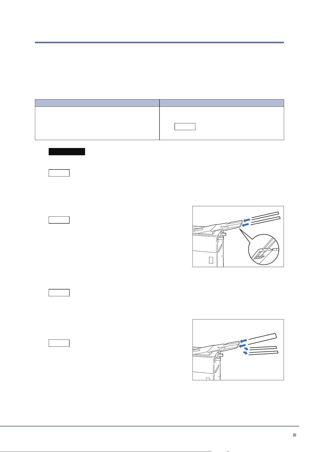
■Extension Tray
Insert 2 extension trays until they stop.
Pass them through over the guide at the rear side of the tray until
they stop.
■ Lightweight paper housing wire
When it is difficult to load thin paper, install the wire.
• The tray capacity is 10 sheets.
• Paper of which width is 256 mm or less cannot be used.
• The supported paper weights are from 82 to 127 g/m
2
.
(1) Remove the 2 Extension Trays and insert the wire mount-
ing U-shaped bar until it stops.
Pass them through over the guide at the rear side of the tray until
they stop.
(2) Install the wires on the U-shaped bar.
Note
Important
Note
Note
Note
Note
Optional Units Manual
50
As holding the U-shaped bar with a hand, insert the fixing devices
firmly, and check that the wires will not come off from the U-shaped
bar.
(3) Adjust the wire positions according to the size of paper to
be output.
Install the wires in parallel.
■ When not using the kit
(When Finisher is installed)
Store the kit in the storage case at the rear side of Finisher.
(When Finisher is not installed)
Hang the kit on the holder at the side of the stacker.
Note
Note
High Capacity Stacker
51
Paper Jams
The error indicator at the top of the machine is turned on. When the priority device indicator (top lamp) blinks,
first of all perform the paper jam operation.
If paper is jammed, the machine stops and an alarm sounds. Follow the instructions displayed on
the screen to remove the jammed paper.
Gently remove the paper being careful not to tear it. If paper is torn while it is being removed from
the machine, remove all the torn pieces making sure that none remain inside the machine.
When you have finished clearing the paper jam, printing is resumed from the state before the pa-
per jam occurred.
Clear the paper jams while the machine is on.
1. Remove the jammed paper.
When Indicator E1 is Turned on .................................................................................................p.51
When Indicator E2 is Turned on .................................................................................................p.51
When Indicator E3 is Turned on .................................................................................................p.52
When Indicator E4 is Turned on .................................................................................................p.52
When Indicator E5 is Turned on .................................................................................................p.52
When Indicator E6 is Turned on .................................................................................................p.53
When Indicator E7 is Turned on .................................................................................................p.53
When Indicator E8 is Turned on .................................................................................................p.54
■When Indicator E1 is Turned on
(1) Open the front upper cover.
(2) Open lever [1b] upward (
1
) and remove the jammed pa-
per (
2
).
(3) Return lever [1b].
(4) Close the cover.
■When Indicator E2 is Turned on
(1) Open the front upper cover.
(2) Open lever [1b] upward (
1
), turn knob [1a] counter-
clockwise (
2
), and remove the jammed paper (
3
).
(3) Return lever [1b].
(4) Close the cover.
Note
Note
1
2
1
2
3
Optional Units Manual
52
■When Indicator E3 is Turned on
(1) Open the front upper cover.
(2) Open lever [1b] upward (
1
), turn knob [1a] counter-
clockwise (
2
), and remove the jammed paper (
3
).
(3) Return lever [1b].
(4) Open lever [2b] upward (
1
), turn knob [2c] counter-
clockwise (
2
), and remove the jammed paper (
3
).
(5) Return lever [2b].
(6) Close the cover.
■When Indicator E4 is Turned on
(1) Open the front upper cover.
(2) Open lever [2a] downward (
1
) and remove the jammed
paper (
2
).
(3) Return lever [2a].
(4) Close the cover.
■When Indicator E5 is Turned on
(1) Open the front upper cover.
(2) Open lever [2b] upward (
1
), turn knob [2c] counter-
clockwise (
2
), and remove the jammed paper (
3
).
(3) Return lever [2b].
(4) Close the cover.
1
2
3
1
2
3
1
2
1
2
3
High Capacity Stacker
53
■When Indicator E6 is Turned on
(1) Press the paper eject button.
(2) When lock is released, open the front lower cover.
(3) Pull out the stacker cart slowly and remove the jammed
paper.
(4) Return the stacker cart slowly.
(5) Close the cover.
■When Indicator E7 is Turned on
(1) Remove the jammed paper that sticks out from the exit of
the Top Output Tray.
(2) Open the front upper cover.
(3) Open lever [1b] upward (
1
) and remove the jammed pa-
per (
2
).
(4) Return lever [1b].
(5) Open lever [2a] downward (
1
) and remove the jammed
paper (
2
).
(6) Return lever [2a].
(7) Close the cover.
1
2
1
2
Optional Units Manual
54
■When Indicator E8 is Turned on
(1) Open the front upper cover.
(2) Open lever [3b] upward (
1
), turn knob [3a] clockwise
(
2
), and remove the jammed paper (
3
).
(3) Return lever [3b].
(4) Close the cover.
2. Check the curl direction of the jammed paper and correct the curl.
"Curl Correction" (p.36)
2
1
3
Refer
Crease / Two-Sided Trimmer
55
7 Crease / Two-Sided Trimmer
Device Components / Caution Labels
E1 E2 E3
E4 E5 E6
E7
1
2
3
4
No. Component Function
1
Error Indicator When paper jam occurs, the indicator is turned on.
When the priority device indicator (top lamp) blinks, first of all perform the paper jam
operation.
2
Waste full indicator When cut pieces need to be disposed, the indicator is turned on. When cut pieces be-
come full, the indicator blinks.
3
Upper Cover Open this cover to clear paper jams.
4
Lower Cover Open this cover to dispose cut pieces.
Optional Units Manual
56
Main Specifications
Item Description
Two-sided Trim Paper size Standard size:
Max SRA3 (320 x 450 mm), 12.6×19.2“ (320 x 488 mm), Min A4, Letter
Custom size:
194 x 210 mm to 330 x 488 mm
Paper weight 52 to 350 g/m
2
Trim dimensions One side: 6 to 25 mm
Crease Paper size Standard size:
Max SRA3 (320 x 450 mm), 12.6×19.2“ (320 x 488 mm), M Min JIS B5
Custom size:
182 x 210 mm to 330 x 488 mm
Paper weight
*1
60 to 350 g/m
2
Number of lines
*2
1 to 5
Power supply AC 100-240 V +/- 10 %, 4 A (100 V) / 2 A (240 V), 50/60 Hz common
Maximum power consumption 480 W
Dimensions W 605 x D 725 x H 992 mm
Weight 128 kg
*1: When using the booklet finishing, 157 g/m
2
or more is supported for single sheet.
*2: The continuous print speed will decrease significantly as the number of lines increases.
Finisher or Finisher with Booklet Maker is required.
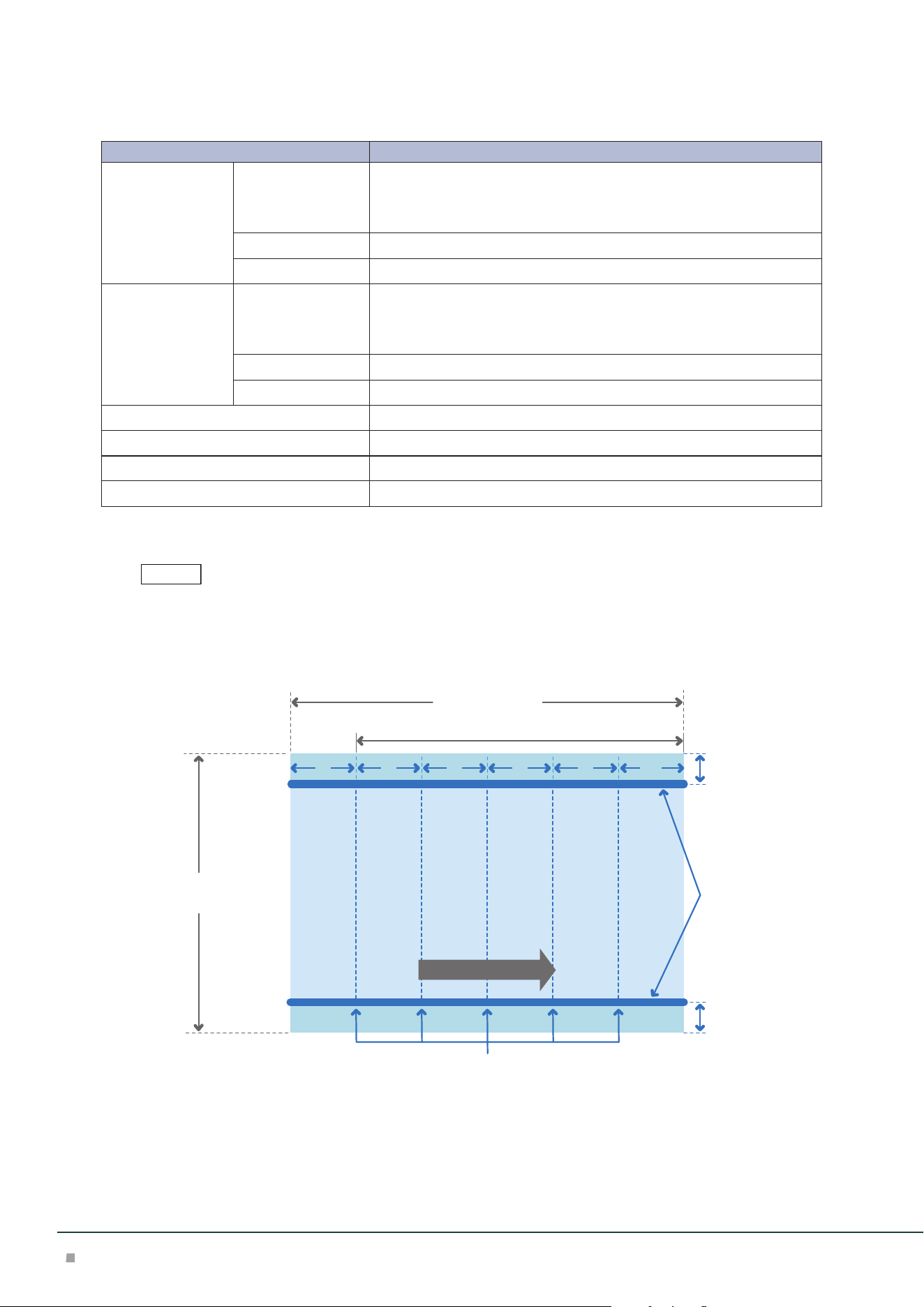
Cutting and Crease Area
A
B
a
e (*)bcd
210 to 488 mm
386 mm or less (trim and crease)
Trim
194 to 330.2 mm (trim)
182 to 330.2 mm (crease)
a: 12 mm or more
b - e: 25 mm or more
Crease
A=B: 6 to 25 mm
Feed direction
Printing is not possible when less than 45 mm from the front edge. Also, the paper feeding capa-
bility is not guaranteed when 62 mm or less from the front edge.
Note
Crease / Two-Sided Trimmer
57
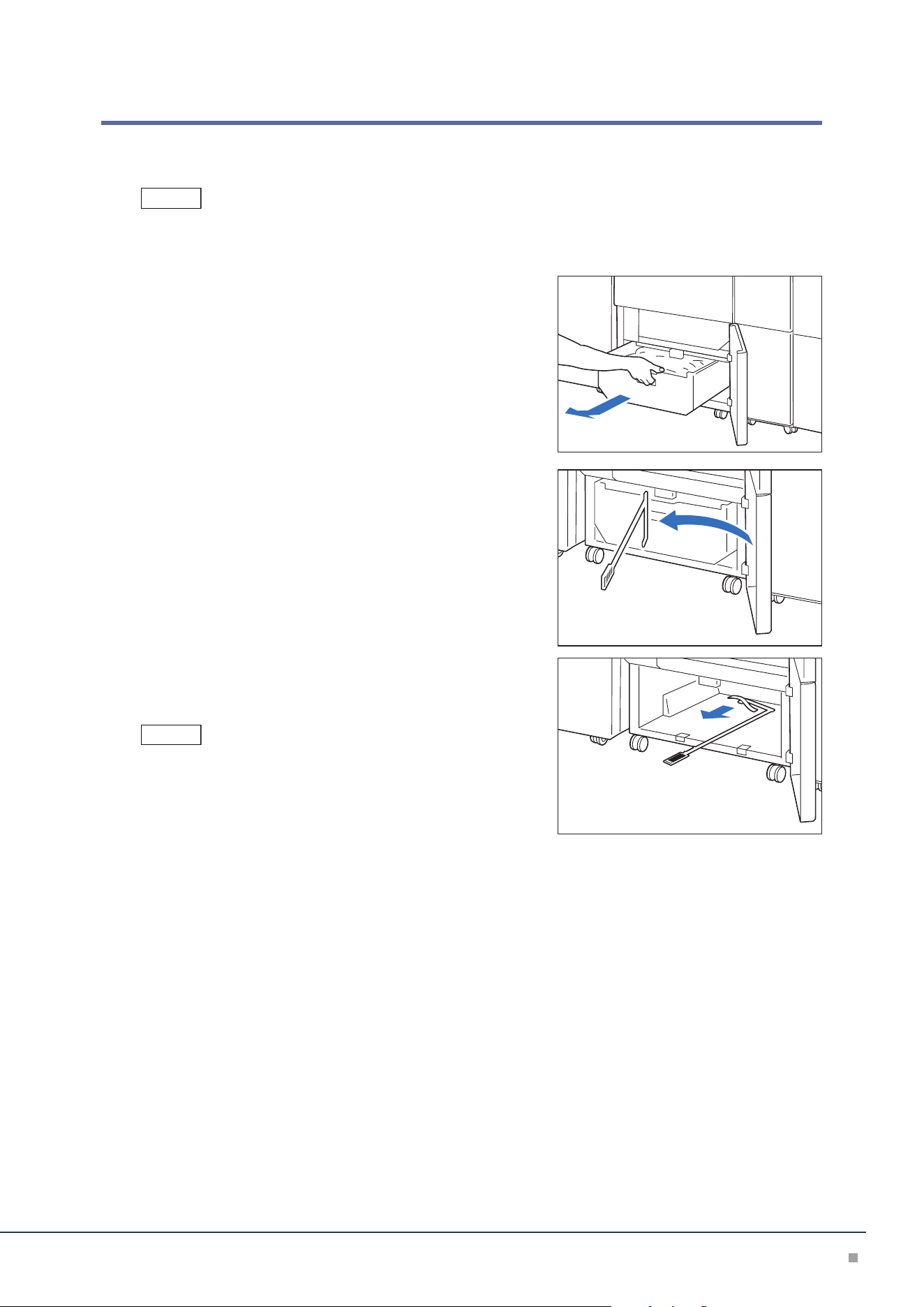
Waste Container
When cut pieces need to be disposed, the waste full indicator is turned on. When it is turned on,
dispose cut pieces.
• Cut pieces can be disposed even during printing.
• When cut pieces in the waste container become full, the waste full indicator changes from ON to blinking.
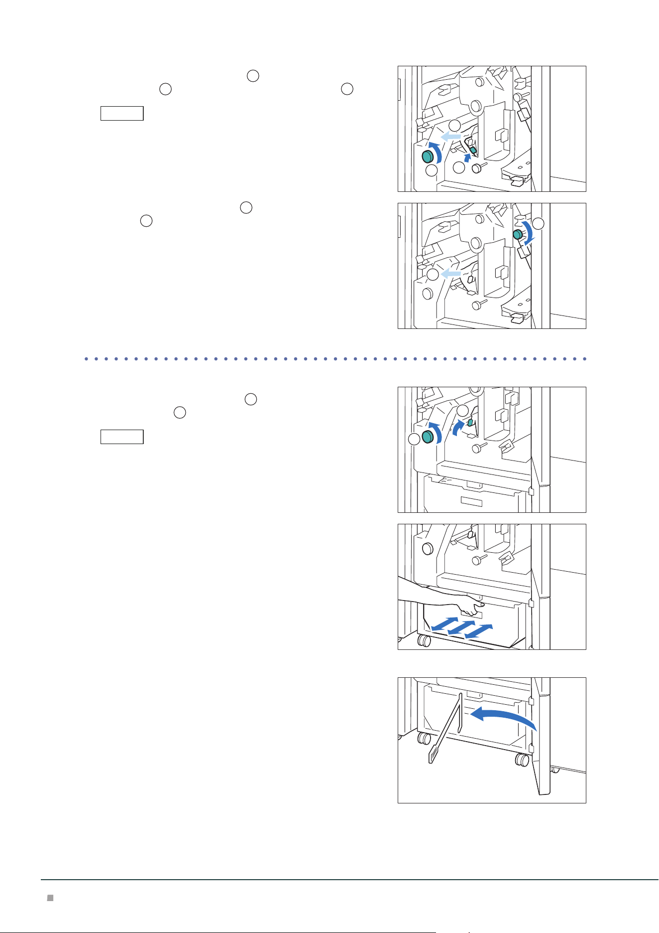
1. Open the lower cover.
2. Pull out the waste container.
3. Dispose all cut pieces.
Confirm that there are no cut pieces at the bottom of the
frame at the rear of the waste container.
Remove cut pieces using a waste collecting bar, if any.
4. Insert the Waste Container into the original position.
Push it until its arrow comes to the frame face.
5. Close the cover.
Note
Note
Optional Units Manual
58
Paper Jams
The error indicator at the top of the machine is turned on. When the priority device indicator (top lamp) blinks,
first of all perform the paper jam operation.
If paper is jammed, the machine stops and an alarm sounds. Follow the instructions displayed on
the screen to remove the jammed paper.
Gently remove the paper being careful not to tear it. If paper is torn while it is being removed from
the machine, remove all the torn pieces making sure that none remain inside the machine.
When you have finished clearing the paper jam, printing is resumed from the state before the pa-
per jam occurred.
Clear the paper jams while the machine is on.
1. Open the upper cover.
2. Remove the jammed paper.
When Indicator E1 is Turned on .................................................................................................p.58
When Indicator E2 is Turned on .................................................................................................p.59
When Indicator E3 is Turned on .................................................................................................p.60
When Indicator E4 is Turned on .................................................................................................p.60
When Indicator E5 is Turned on .................................................................................................p.61
When Indicator E6 is Turned on .................................................................................................p.61
When Indicator E7 is Turned on .................................................................................................p.62
■When Indicator E1 is Turned on
(1) Open lever [1a] downward (
1
), open lever [1b] down-
ward (
2
), open lever [1d] upward (
3
), and remove the
jammed paper (
4
).
Jammed paper may be hidden at the upper section.
(2) If you have difficulty in removing the papers, turn knob
[1c] clockwise (
1
) and remove the jammed paper (
2
).
(3) Return lever [1a], lever [1b], and lever [1d].
Note
Note
Note
1
2
3
4
1
2
Crease / Two-Sided Trimmer
59
■When Indicator E2 is Turned on
(1) Turn knob [2] counterclockwise and align the marks.
(2) Open lever [1a] downward (
1
) and open lever [1b]
downward (
2
).
(3) Turn knob [1c] clockwise (
1
) and remove the jammed
paper (
2
).
(4) Return lever [1a] and lever [1b].
(5) If you have difficulty in removing the papers, open lever
[1d] upward (
1
) and open lever [2a] to the left (
2
).
(6) Turn knob [2b] counterclockwise (
1
) and remove the
jammed paper (
2
).
(7) Return lever [1d] and lever [2a].
1
2
1
2
1
2
1
2
Optional Units Manual
60
■When Indicator E3 is Turned on
(1) Turn knob [2] counterclockwise and align it with the mark
position.
(2) Open lever [2c] downward (
1
) and remove the jammed
paper (
2
).
Jammed paper may be hidden at the upper section.
(3) Return lever [2c].
■When Indicator E4 is Turned on
(1) Open lever [2c] downward (
1
), open lever [2d] upward
(
2
), and open lever [2e] to the right (
3
).
(2) Hold the lead edge of paper, turn knob [2f] clockwise
(
1
), and remove the jammed paper (
2
).
If you have difficulty in removing the papers, hold the trail
edge of the paper and remove it.
(3) Return lever [2e], lever [2d], and lever [2c].
Note
1
2
1
2
3
1
2
Crease / Two-Sided Trimmer
61
■When Indicator E5 is Turned on
(1) Open lever [3a] to the right (
1
) and open lever [3b] to
the left (
2
).
(2) Turn knob [3c] clockwise (
1
) and remove the jammed
paper (
2
).
(3) Turn knob [2f] counterclockwise (
1
) and remove the
jammed paper (
2
).
(4) Return lever [3a] and lever [3b].
■When Indicator E6 is Turned on
(1) Open lever [3a] to the right (
1
), open lever [4b] down-
ward (
2
), open lever [4c] to the right (
3
), and remove
the jammed paper (
4
).
(2) Turn knob [4d] counterclockwise (
1
) and remove the
jammed paper (
2
).
1
2
1
2
1
2
1
2
3
4
1
2
Optional Units Manual
62
(3) Open lever [4a] to the right (
1
), turn knob [2f] counter-
clockwise (
2
), and remove the jammed paper (
3
).
As holding the lever [4a] with a hand, turn knob [2f] and remove the
paper.
(4) Turn knob [3c] clockwise (
1
) and remove the jammed
paper (
2
).
(5) Return lever [3a], lever [4b], and lever [4c].
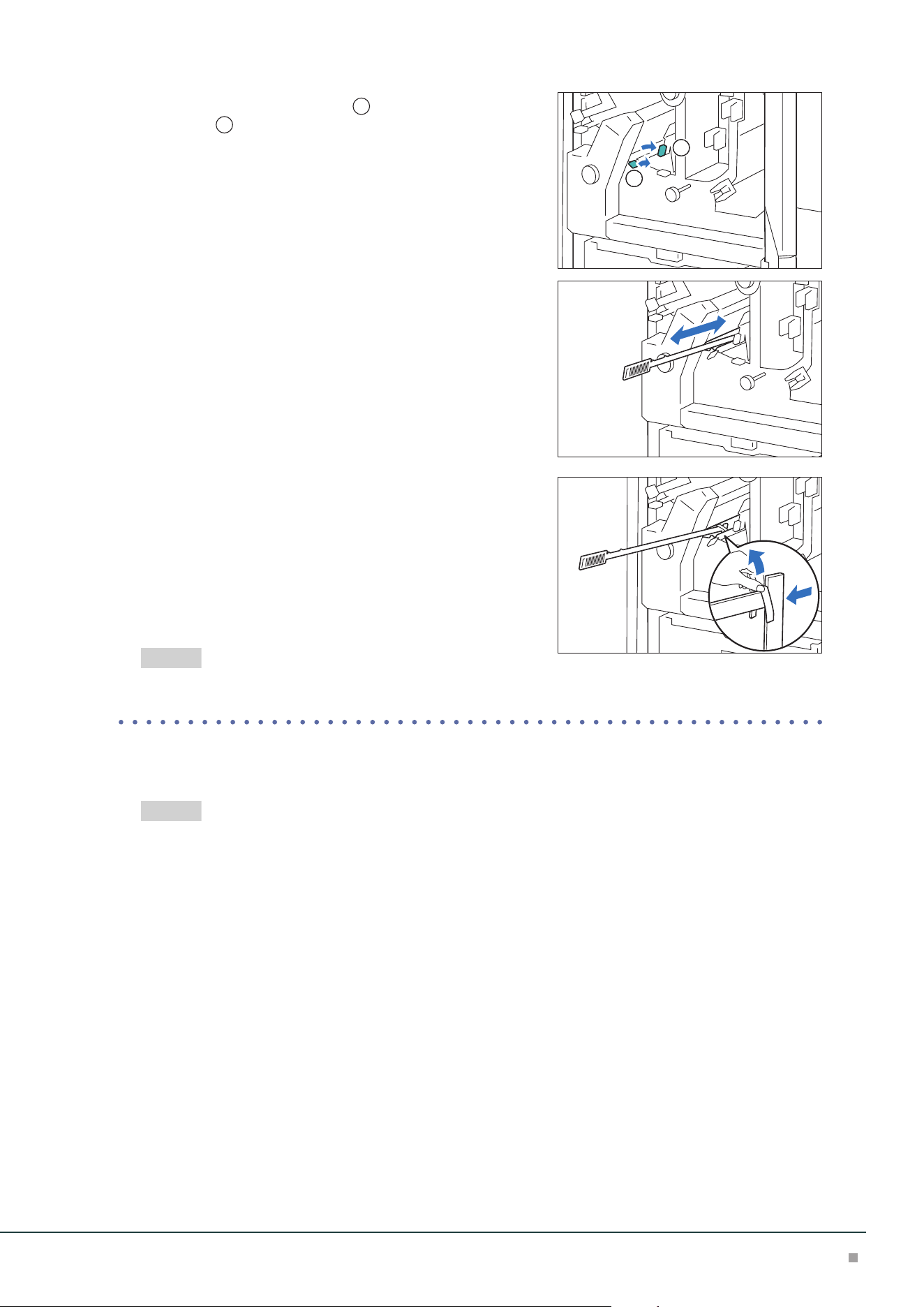
■When Indicator E7 is Turned on
(1) Open lever [3a] to the right (
1
) and turn knob [2f] coun-
terclockwise (
2
).
Make sure to turn knob 5 times or more.
(2) Pull out and insert the Waste Container 3 times.
(3) Return lever [3a].
■ When the indicator is not turned off
(1) Remove the waste collecting bar in the cover.
Note
1
2
3
1
2
Note
1
2
Crease / Two-Sided Trimmer
63
(2) Open lever [3a] to the right (
1
) and open lever [3d] to
the right (
2
).
(3) Collect cut pieces around the trimmer unit in the waste
container using the waste collecting bar.
(4) If cut pieces cannot be collected in the waste container,
move them by the waste collecting bar and remove them
with hands.
(5) Return lever [3a] and lever [3d].
(6) Confirm that there are no cut pieces at the bottom of the
frame at the rear of the waste container.
Remove cut pieces using a waste collecting bar, if any.
"Waste Container" (p.57)
3. Close the cover.
4. Check the curl direction of the jammed paper and correct the curl.
"Curl Correction" (p.36)
2
1
Refer
Refer
Optional Units Manual
64
8 Folder Unit
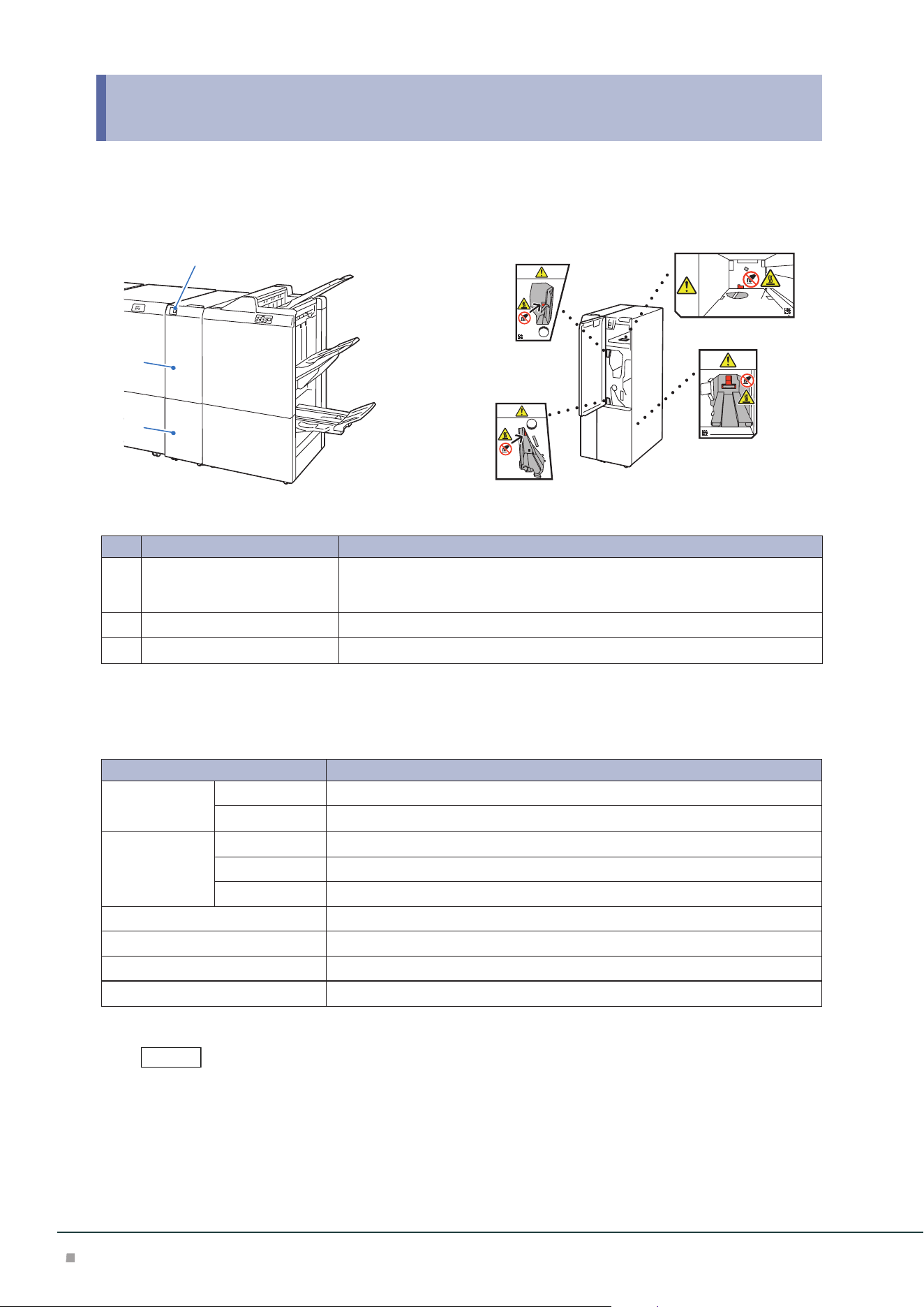
Device Components / Caution Labels
2
3
1
Bottom
No. Component Function
1
Tri-Fold Output Tray Button Press the button to remove paper from the Tri-Fold Output Tray.
The Tri-Fold Output Tray is opened when the lamp stops blinking and comes on
and the lock is released.
2
Cover Open this cover to clear paper jams.
3
Tri-Fold Output Tray Paper is ejected only to this tray in case of inner C Fold/Z Fold sheets.
Main Specifications
Item Description
Z-Fold Half
Sheet
Paper size A3, 11 x 17”, JIS B4
Paper weight 60 to 90 g/m
2
Tri-fold Paper size A4, Letter
Paper weight 60 to 90 g/m
2
Paper capacity
*1
30 sheets
Power supply AC 100-127 V +/- 10 %, 1 A, AC 200-240 V +/- 10 %, 0.6 A, 50/60 Hz common
Maximum power consumption 120 W
Dimensions W 232 x D 725 x H 992 mm
Weight 48 kg
*1: 82 g/m2 paper
Folder Unit is an option for Finisher and Finisher with Booklet Maker.
Note
Folder Unit
65
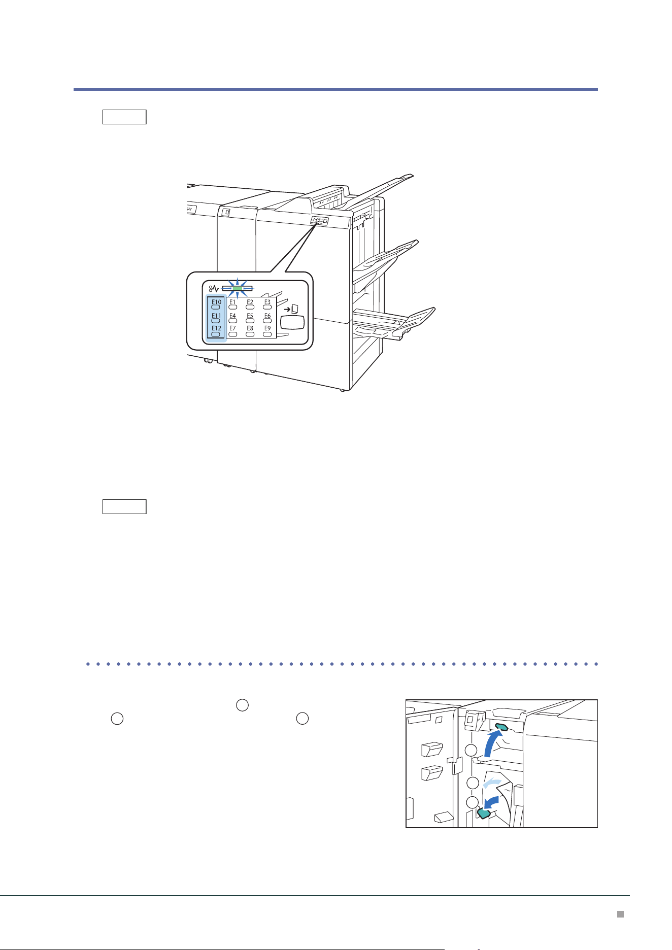
Paper Jams
The error indicator at the top of the Finisher is turned on. When the priority device indicator (top lamp) blinks, first
of all perform the paper jam operation.
If paper is jammed, the machine stops and an alarm sounds. Follow the instructions displayed on
the screen to remove the jammed paper.
Gently remove the paper being careful not to tear it. If paper is torn while it is being removed from
the machine, remove all the torn pieces making sure that none remain inside the machine.
When you have finished clearing the paper jam, printing is resumed from the state before the pa-
per jam occurred.
Clear the paper jams while the machine is on.
1. Open the Cover.
2. Remove the jammed paper.
When Indicator E10 is Turned on...............................................................................................p.65
When Indicator E11 is Turned on...............................................................................................p.66
When Indicator E12 is Turned on...............................................................................................p.66
■When Indicator E10 is Turned on
(1) Open lever [2a] upward (
1
), open lever [2b] to the left
(
2
), and remove the jammed paper (
3
).
(2) Return lever [2a] and lever [2b].
Note
Note
1
2
3
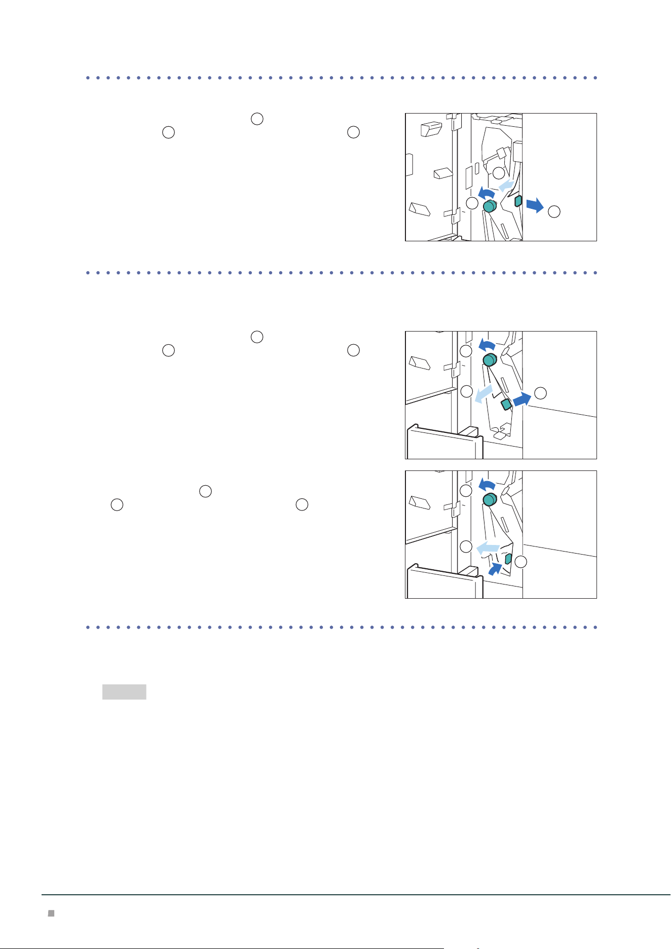
Optional Units Manual
66
■When Indicator E11 is Turned on
(1) Open lever [2g] to the right (
1
), turn knob [2c] counter-
clockwise (
2
), and remove the jammed paper (
3
).
(2) Return lever [2g].
■When Indicator E12 is Turned on
(1) Pull out the Tri-Fold Output Tray [2d].
(2) Open lever [2e] to the right (
1
), turn knob [2c] counter-
clockwise (
2
), and remove the jammed paper (
3
).
(3) Return lever [2e].
(4) If you have difficulty in removing the papers, open lever
[2f] to the right (
1
), turn knob [2c] counterclockwise
(
2
), and remove the jammed paper (
3
).
(5) Return lever [2f].
(6) Return the Tri-Fold Output Tray [2d] to the original posi-
tion.
3. Close the cover.
4. Check the curl direction of the jammed paper and correct the curl.
"Curl Correction" (p.36)
1
2
3
1
2
3
1
2
3
Refer
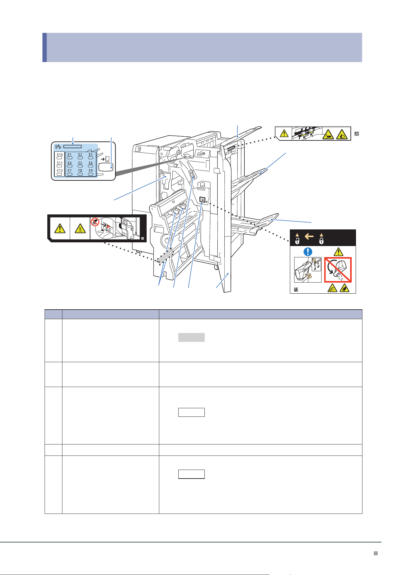
Finisher
67
9 Finisher
In this guide, “Finisher” and “Finisher with Booklet Maker” are generally referred to as “Finisher”.
Device Components / Caution Labels
6
78
9
10
4
1
5
2 3
No. Component Function
1
Hole Punch Waste Container Punched pieces go in here.
For the discard method of waste in the waste container, refer to the
label affixed on the machine.
2
Error Indicator When paper jam occurs, the indicator is turned on.
When the priority device indicator (top lamp) blinks, first of all perform the
paper jam operation.
3
Booklet output button When the button is pressed, paper output in the Booklet Tray is moved to
the collecting position.
When the Square Back Fold Trimmer is equipped, pressing of but-
ton moves to the Booklet Tray removal position of the Square Back
Fold Trimmer.
4
Top Output Tray Outputs are delivered here.
5
Finisher Tray Side stitch paper is ejected.
When 2,000 sheets or more of paper with large downward curl are
output, a stack of output sheets may fall.
In this case, set the lowest curl correction of Interface Decurler
Module and downward curl correction of Inserter.
Refer
Note
Note
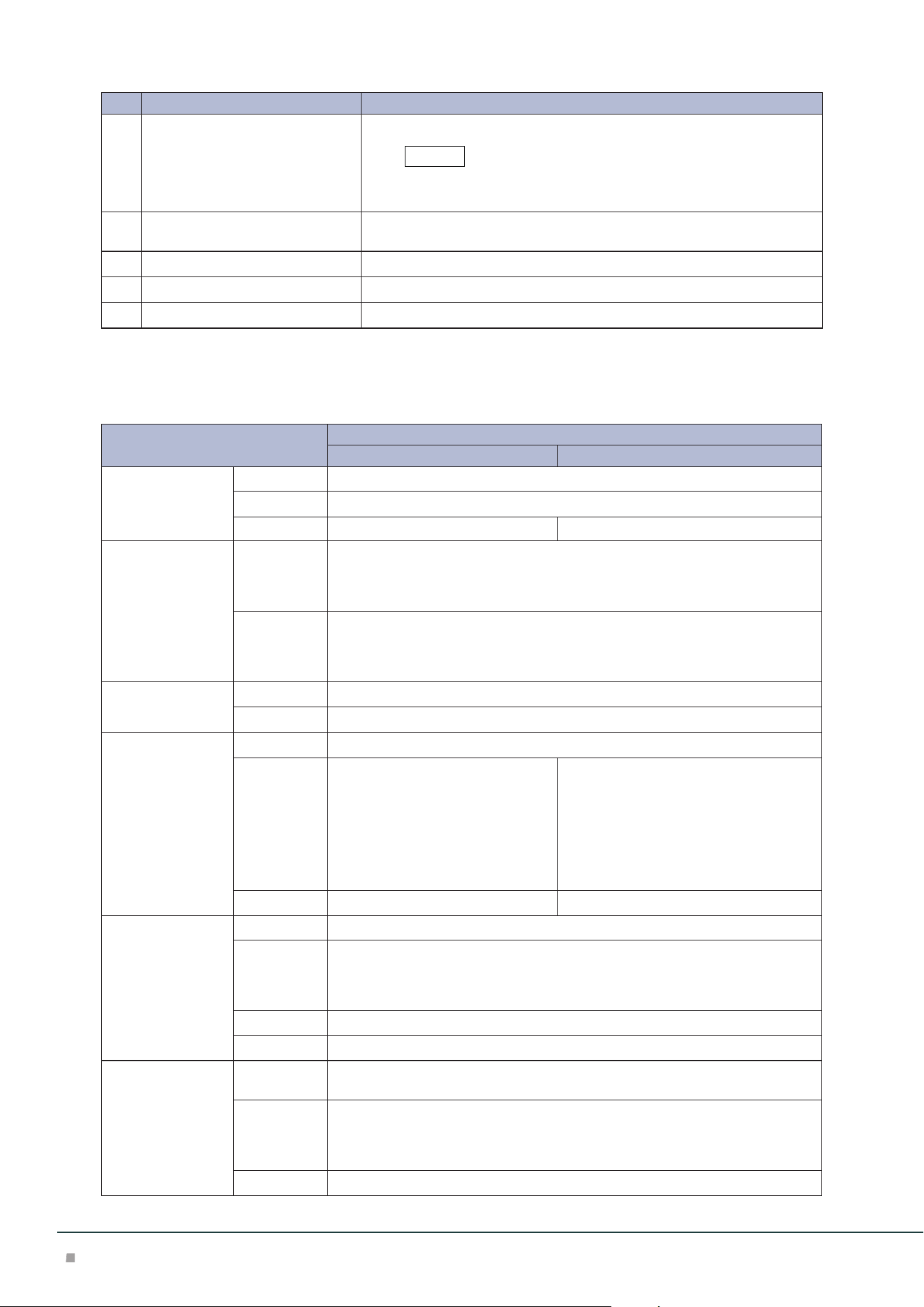
Optional Units Manual
68
No. Component Function
6
Booklet Tray Saddle stitch and single fold paper is ejected.
When the Square Back Fold Trimmer is equipped, it is installed to
the Square Back Fold Trimmer.
7
Cover Open this cover to clear paper jams, replace the Staple Cartridge, remove
jammed staples or dispose of cut pieces for punched holes.
8
Staple Waste Container Staple waste goes in here.
9
Staple Cartridge for side stitch This unit is used to replace staples for side stitch.
10
Staple Cartridges for saddle stitch This unit is used to replace staples for saddle stitch. There are two.
Main Specifications
Item
Description
Finisher Finisher with Booklet Maker
Type Output Tray Sort / Stack
Finishing Tray Sort (Offset available) / Stack (Offset available)
Booklet Tray - Sort / Stack
Paper size Output Tray Standard Size:
Max SRA3 (320 x 450 mm), 12.6×19.2“ (320 x 488 mm), Min A6
Custom Size:
98 x 148 mm to 330 x 1200 mm
*1
Finishing Tray Standard Size:
Max SRA3 (320 x 450 mm), 12.6×19.2“ (320 x 488 mm), Min A5
Custom Size:
148 x 148 mm to 330 x 488 mm
Paper weight Output Tray 52 to 400 g/m
2
Finishing Tray 52 to 350 g/m
2
Paper capacity
*2
Output Tray 500 sheets (A4)
Finishing Tray [Without Stapling]
A4: 3000 sheets
JIS B4 or larger: 1500 sheets
Mixed Size Stacking
*3
: 350 sheets
[With Stapling]
A4: 200 sets or 3000 sheets
JIS B4 or larger: 100 sets or 1500
sheets
[Without Stapling]
A4: 2000 sheets
JIS B4 or larger: 1500 sheets
Mixed Size Stacking
*3
: 350 sheets
[With Stapling]
A4: 200 sets or 2000 sheets
JIS B4 or larger: 100 sets or 1500 sheets
Booklet Tray - 20 sets
*4
Staple Capacity 100 sheets (90 g/m
2
or less)
*5
Paper size
*6
Standard Size:
Max A3, 11 x 17", Min JIS B5
Custom Size:
182 x 182 mm to 297 x 432 mm
Paper weight 52 to 350 g/m
2
Position Single stapling
*7
, Dual stapling, 4 stapling
Punch
*8
Number of
Holes
2-hole / 4-hole punch or 2-hole / 3-hole punch
Paper size
*9
Standard Size:
Max A3, 11 x 17", Min JIS B5 (2-hole punch, 3-hole punch), A4 (4-hole punch)
Custom Size:
203 x 182 mm to 297 x 431 mm
Paper weight 52 to 220 g/m
2
Note
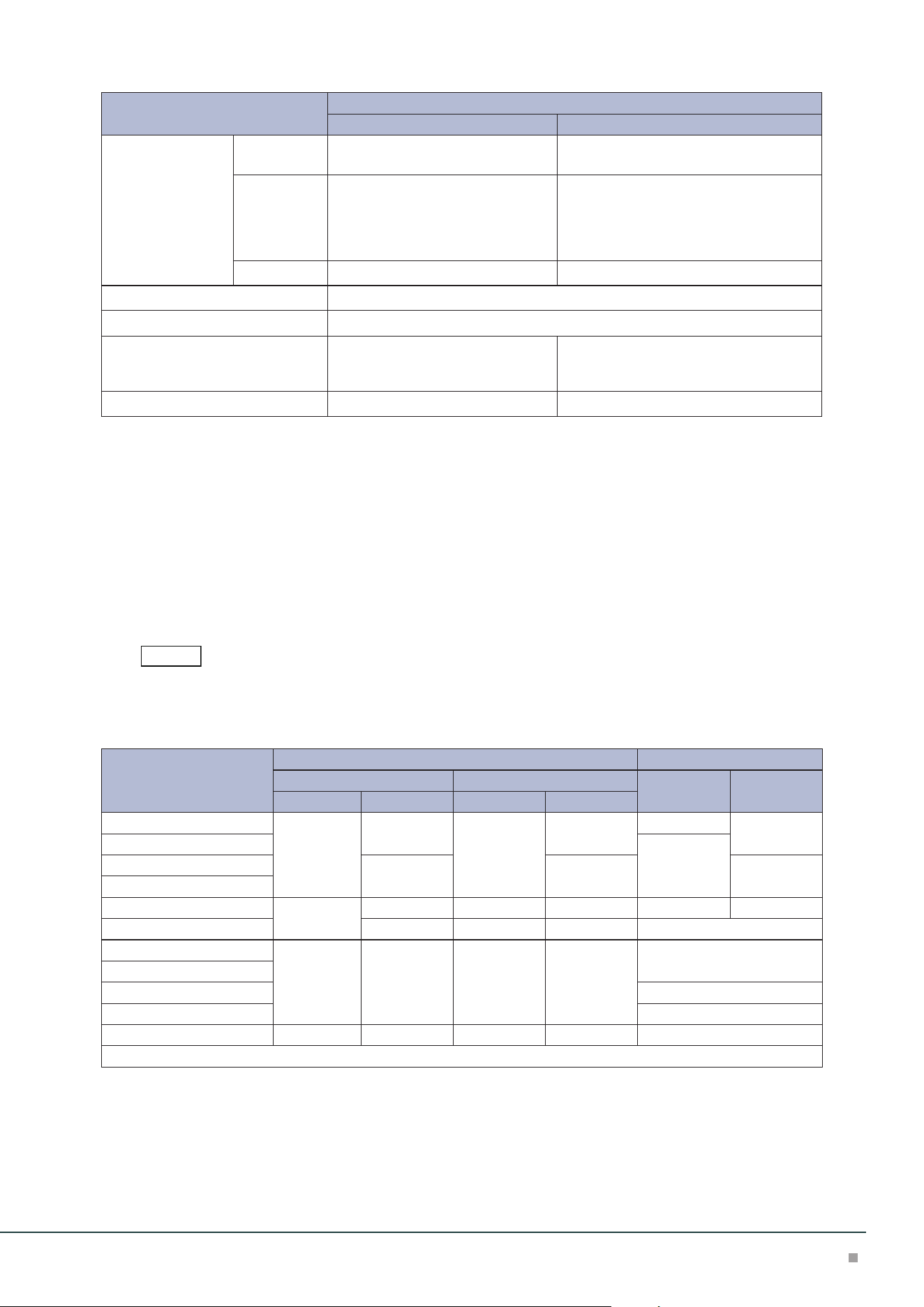
Finisher
69
Item
Description
Finisher Finisher with Booklet Maker
Booklet Finishing Capacity
*10
- Saddle Staple: 30 sheets (90 g/m
2
or less)
Single Fold: 5 sheets (220 g/m
2
or less)
Paper size - Standard Size:
Max SRA3 (320 x 450 mm), 12.6×19.2“
(320 x 488 mm), Min JIS B5
Custom Size:
182 x 257 mm to 330 x 488 mm
Paper weight - 60 to 350 g /m
2
Power supply AC 100-127 V +/- 10 %, 3 A, AC 200-240 V +/- 10 %, 1.8 A, 50/60 Hz common
Maximum power consumption 360 W
Dimensions W 855 x D 725 x H 1204 mm
With Folder Unit:
W 1092 x D 725 x H 1204 mm
With Folder Unit:
W 1129 x D 725 x H 1204 mm
Weight 82 kg 102 kg
*1: For paper longer than 330 x 488 mm, the capacity is not guaranteed. When the optional Banner Print
Extension Kit is installed, 150 sheets of long paper up to 330 x 660 mm; 100 sheets of long paper up to
330 x 729 mm; 10 sheets of long paper up to 330 x 1200 mm can be stacked.
*2: 82 g/m2 paper
*3: When larger size sheets are stacked on top of smaller size sheets.
*4: 16 sets (17-20 sheets per print), 12 sets (21-25 sheets per print), 10 sets (26-30 sheets per print).
*5: 65 sheets for sizes exceeding A4.
*6: Available staple positions vary depending on the paper size.
*7: One place rear angled stapling is supported on A4 and A3.
*8: Optional.
*9: Available number of punch holes varies depending on the paper size.
*10: The maximum number of sheets varies depending on the paper weight. Booklet may not be tightly
closed depending on the size or type of the paper.
Interface Decurler Module is required.
Number of Sheets That can be Stapled (Approximation)
Paper weight (g/m
2
)
Side stitch Saddle stitch
When A4 size or less When exceeding A4 size
Uncoated Coated
Uncoated Coated Uncoated Coated
52 to 59 100 35* 65 35* 30* 25*
60 to 71 30
72 to 80 35 35 25
81 to 90
91 to 105 50 30* 50 30* 20 20*
106 to 128 30 45 30 15
129 to 150 20 20 20 20 10
151 to 176
177 to 220 5
221 to 256 4
257 to 350 10 10 10 10 3
*: Although staple is available, the stitch accuracy and paper feeding capability are not guaranteed.
Note
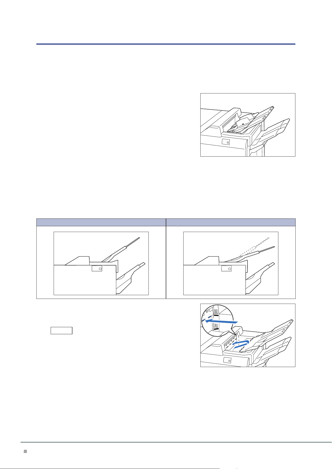
Optional Units Manual
70
Outputting Paper
Top Output Tray
Loading Guide
Place it on the Top Output Tray when using an envelope.
Changing Angle
Change the angle when output paper remains at the exit and paper full is detected immediately.
Especially in the following case, paper full is likely to be detected, change the angle to the B posi-
tion.
• Thin coated paper
• Coated paper with the length of 364 mm or more
• Long paper
A B
Pull the Top Output Tray to the right, remove it from the
lower fixed position (A), and insert the claws at the front
edge of the tray to the upper fixed position (B).
• Normally set the tray at the lower fixed position.
If the tray is at the upper fixed position of the exit, paper may fall
from the Top Output Tray and a paper jam may occur when paper
is output to the Finisher tray.
• If paper is curled, the effectiveness of angle change cannot be ob-
tained.
Note
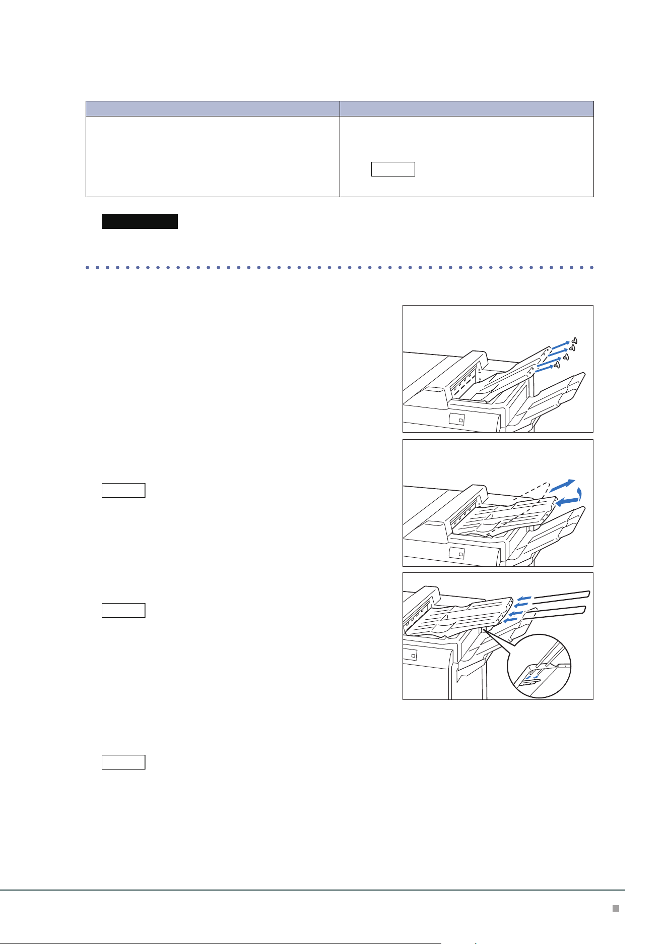
Finisher
71
■Banner Print Extension Kit
Long paper can be loaded without its lead edge sticking out.
Paper size (mm) Tray capacity (sheets)
Width: 210 to 330.2
Length: 488.1 to 1,200
Up to 660 mm: 150
Up to 729 mm: 100
More than 729.1 mm: 10
This value applies if 82 g/m2 paper is used.
When paper exceeding the tray capacity is loaded, the Extension Tray may get broken.
■Extension Tray
(1) Push the Top Output Tray from the rear side as pinching
the cap and remove the 4 caps at the front edge of the Top
Output Tray.
(2) Change the angle of the Top Output Tray to the upper
fixed position (B).
Change the angle to the lower fixed position (A) for paper with the
width of 256 mm or less.
(3) Insert 2 extension trays until they stop.
Pass them through over the guide at the rear side of the tray until
they stop.
■ Lightweight paper housing wire
When it is difficult to load thin paper, install the wire.
• The tray capacity is 10 sheets.
• Paper of which width is 256 mm or less cannot be used.
• The supported paper weights are from 82 to 209 g/m
2
.
Note
Important
Note
Note
Note
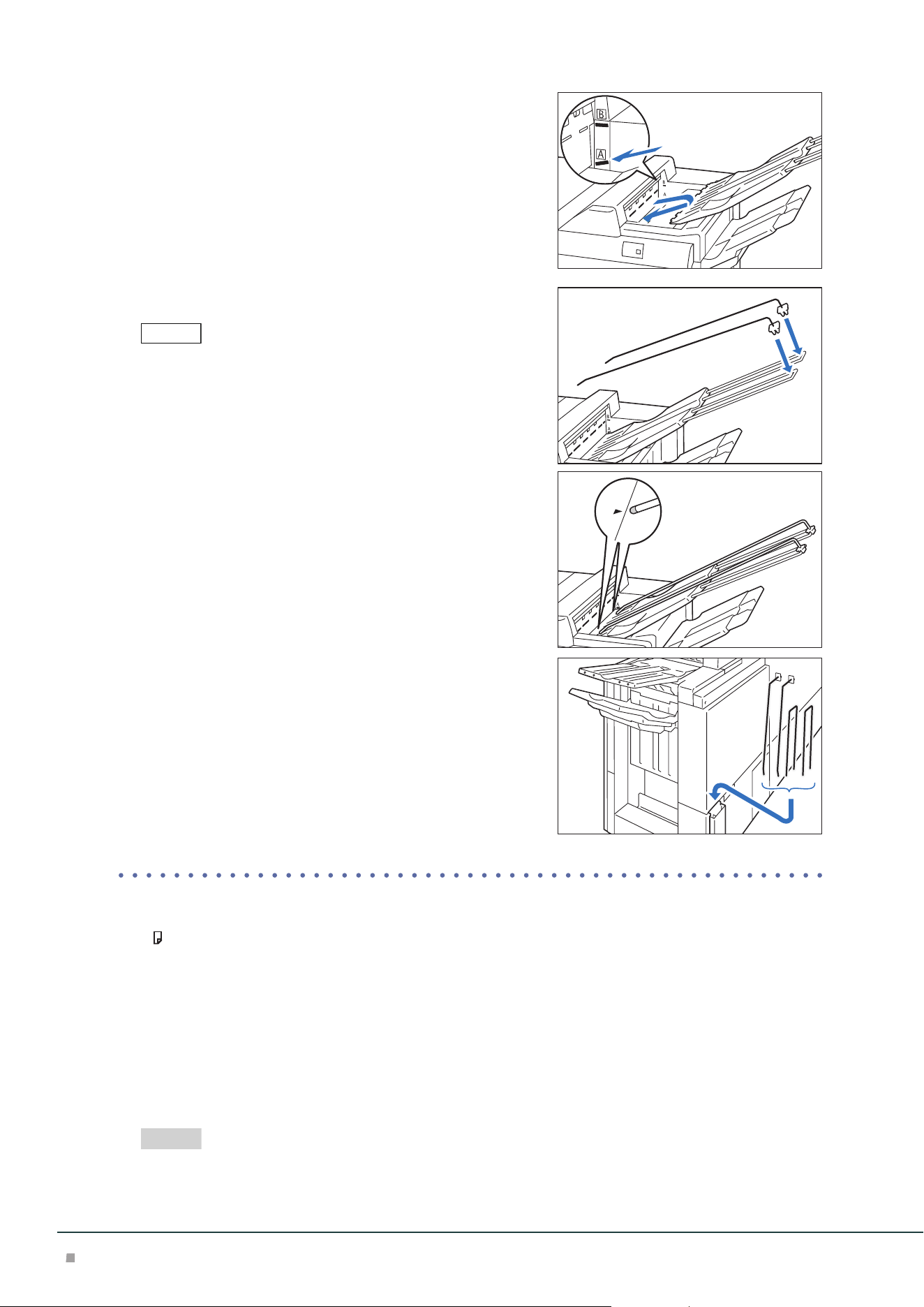
Optional Units Manual
72
(1) Change the angle of the Top Output Tray to the lower fixed
position (A).
(2) Install the wires on the extension trays.
As holding the extension tray with a hand, insert the fixing devices
firmly, and check that the wires will not come off from the extension
tray.
(3) Adjust the wire positions as aligning the wires with the
“” marks.
■ When not using the kit
Store the kit in the storage case at the rear side of Finisher.
Paper Curl
• If A5 is curled upward, a paper jam may occur.
Set the highest curl correction of Interface Decurler Module and upward curl correction of In-
serter.
• If thick paper is curled downward, a paper jam may occur.
Set the lowest curl correction of Interface Decurler Module and downward curl correction of
Inserter.
• If paper of 157 g/m2 or more is curled upward, a paper jam may occur.
Set the highest curl correction of Interface Decurler Module and upward curl correction of In-
serter.
"Curl Correction" (p.36)
Note
Refer
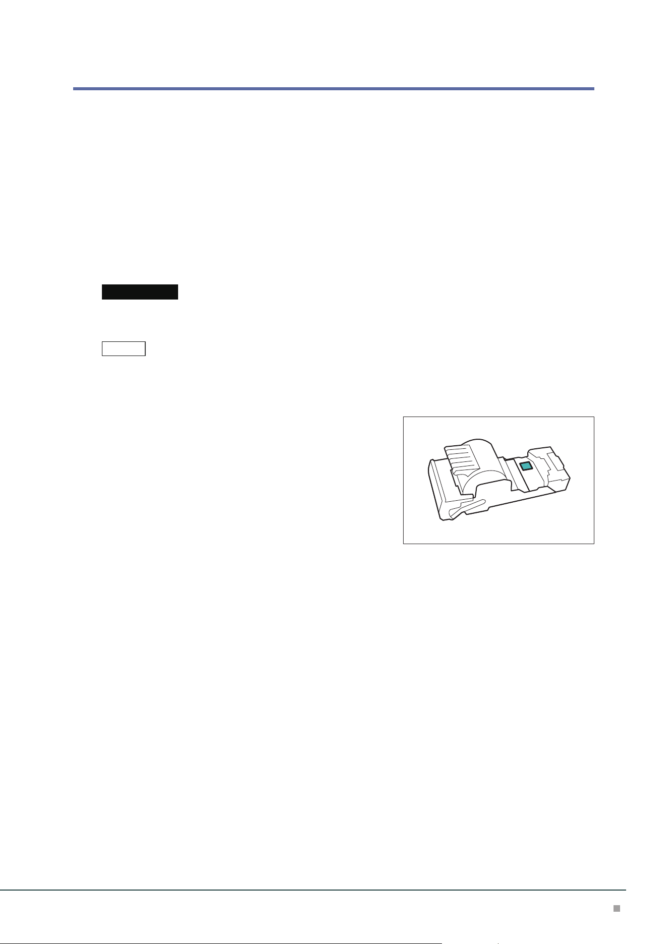
Finisher
73
Staple Cartridge
Replacing Staple Cartridge / Staple Waste Container
Consumables recommended by SHARP are manufactured under the standards suitable for this
machine. Using consumables not recommended by SHARP may affect print quality or perfor-
mance provided by the product. Use consumables that SHARP recommends for this machine.
To place orders for consumables, take a note of the part number and contact your dealer or near-
est SHARP Service Department.
When the end of life for a consumable is reached, a message appears on the Printer User Interface.
Replace the consumable indicated in the message.
For the replacement method, refer to the steps provided on the box of the consumable (or label).
Proper disposal is required for consumables no longer needed. Do not open consumables. Return them to your
dealer or nearest SHARP Service Department.
• Replacing consumable while the machine is on.
• Use up the staples before replacing.
■Staple Cartridge for Side Stitch
You can check the existence of the staples in the residual
quantity window.
Important
Note
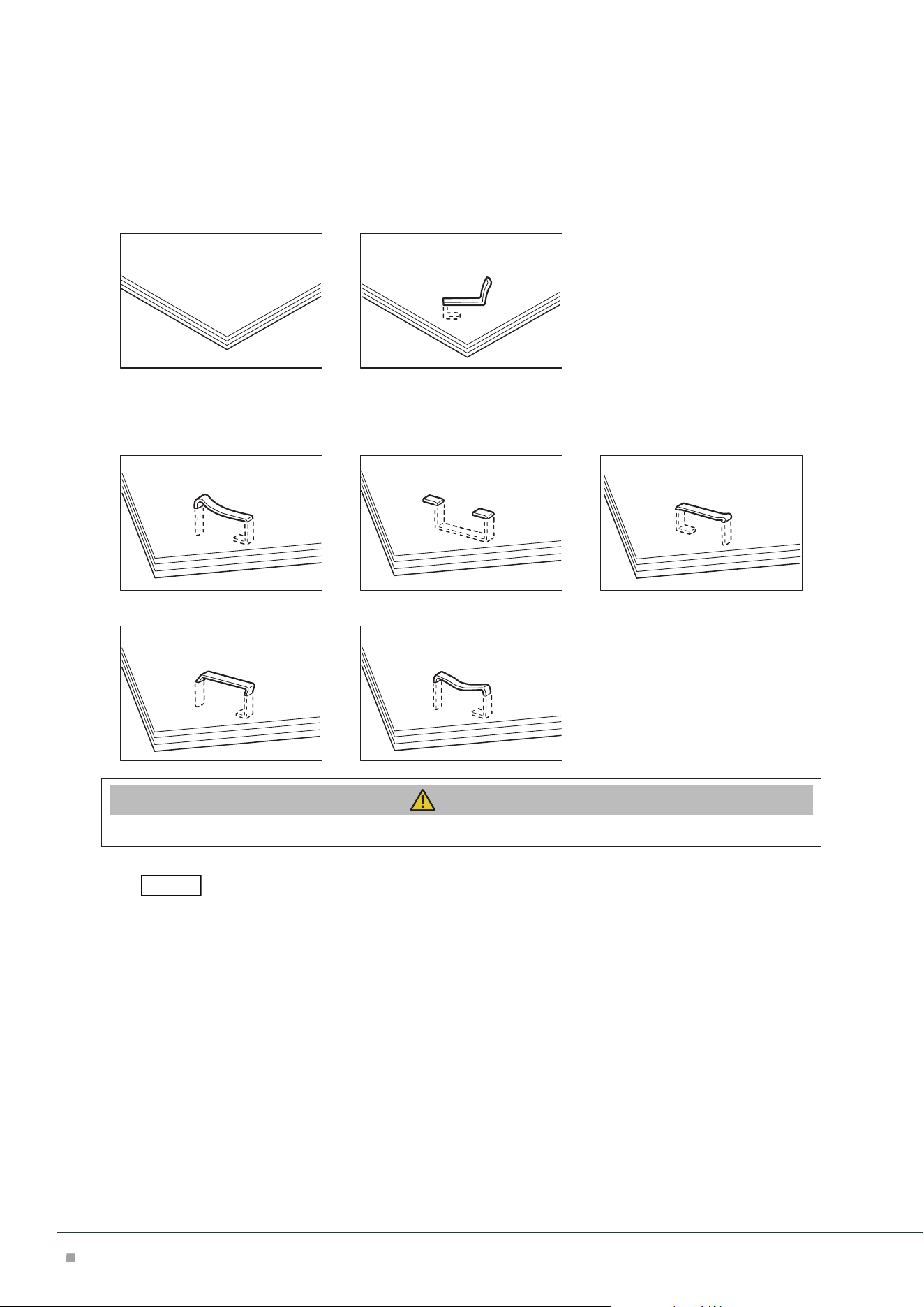
Optional Units Manual
74
Staple Jams
If paper is not being stapled or if staples are bent, follow the procedures mentioned in the follow-
ing pages.
If the issue isn't resolved even after the procedure, contact your dealer or nearest SHARP Service
Department.
Paper is not stapled Staple is bent
If the staple looks like any of the following images, contact your dealer or nearest SHARP Service
Department.
One side of the staple is loose Staple is bent in the wrong direction Staple is collapsed
Staple is loose Staple is loose, and the center sinks
Caution
Please be very careful not to hurt your fingers, etc. when removing the jammed staple.
• Depending on the usage condition, such as the paper type, staples may be bent or bent staples may be caught
inside of the unit, causing paper jamming.
• If you open the Staple Cartridge cover, be sure to remove all bent staples. Not removing bent staples may cause
staple jamming. Only open the Staple Cartridge cover when you are removing the jammed staples.
Note
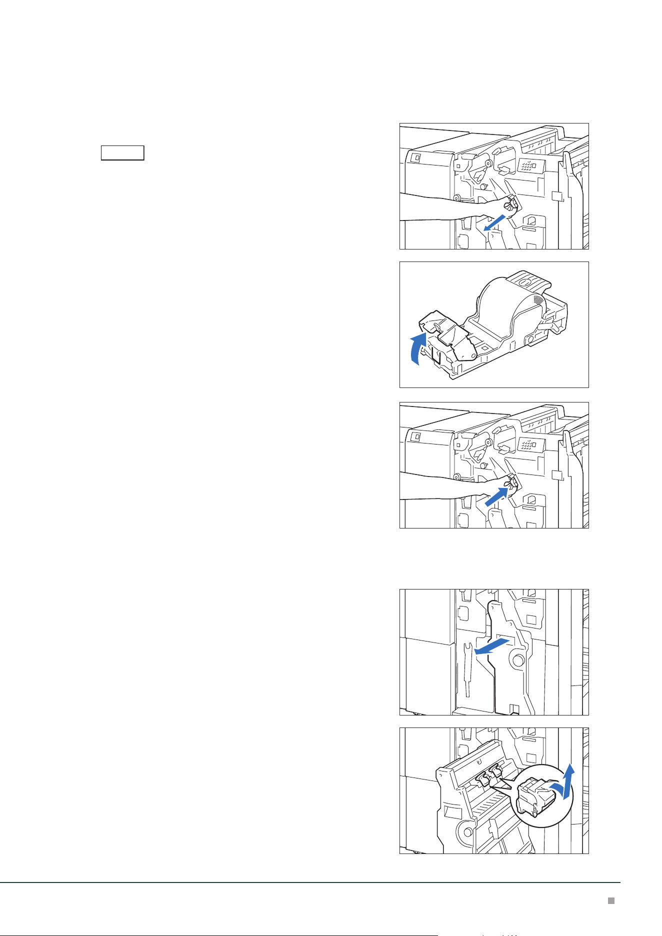
Finisher
75
Staple Cartridge for Side Stitch
1. Confirm that the machine is not operating, and open the Cover.
2. Pull out [R1].
After removing the Staple Cartridge, check to make sure that there
is no staple inside of the Finisher.
3. Open the cover of the unit and remove the jammed
staples.
4. Insert the unit into the original position.
5. Close the cover.
Staple Cartridges for Saddle Stitch
1. Confirm that the machine is not operating, and open the Cover.
2. Pull out Booklet Maker [3].
3. Hold the handle of the Staple Cartridge (R2)(R3) and
pull it out.
Note
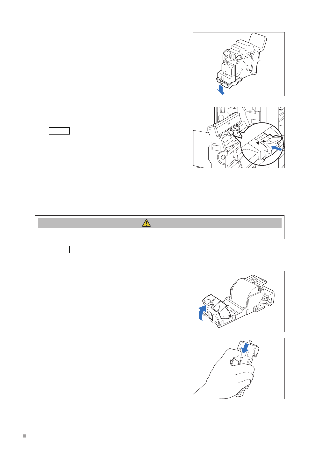
Optional Units Manual
76
4. Remove the jammed staples.
5. Insert the Staple Cartridge into the original position.
Hold the handle and lightly press it up until you hear a click.
Align the “” marks.
6. Push in the Booklet Maker [3].
7. Close the cover.
When Staple Cartridge for Side Stitch Comes off
If the Staple Cartridge comes off from the unit due to fall during operation, etc., perform the fol-
lowing steps.
Caution
Please be very careful not to hurt your fingers, etc. when removing the deformed staples.
Perform the same steps as well when the Staple Cartridge is separated from the unit.
1. Open the cover of the unit and remove all the de-
formed staples.
2. Move the handle on the rear side of the unit in the
arrow direction.
Note
Note
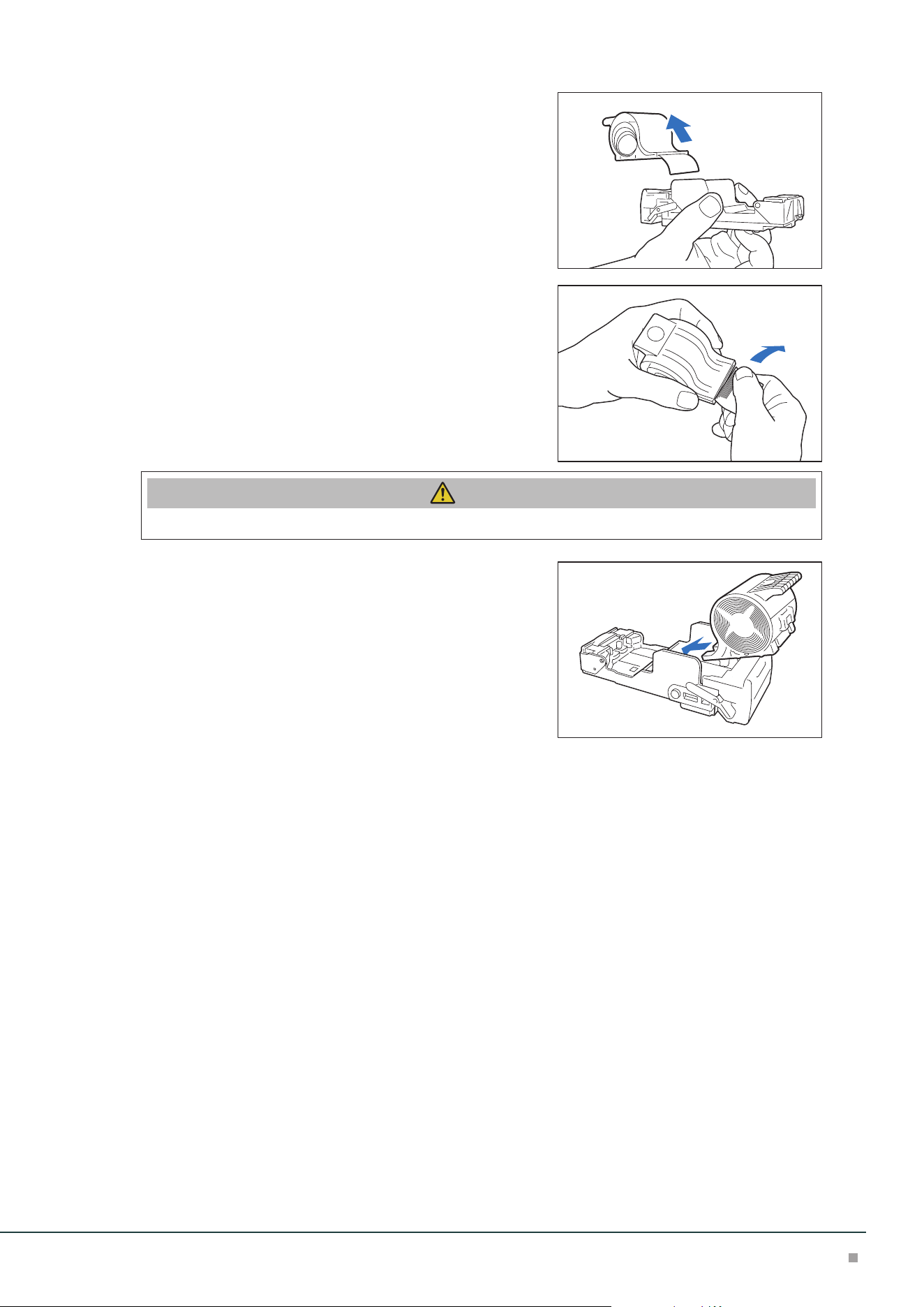
Finisher
77
3. Turn it over as the handle is at the moved position
and take out the Staple Cartridge from the unit.
4. Remove the staples that stick out from the Staple
Cartridge.
Caution
Please be very careful not to hurt your fingers, etc. when separating staples.
5. Insert the Staple Cartridge into the unit.
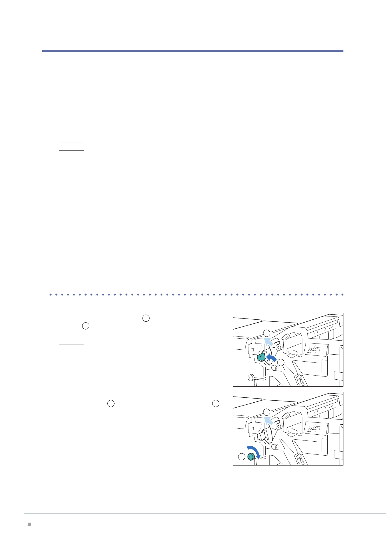
Optional Units Manual
78
Paper Jams
The error indicator at the top of the machine is turned on. When the priority device indicator (top lamp) blinks,
first of all perform the paper jam operation.
If paper is jammed, the machine stops and an alarm sounds. Follow the instructions displayed on
the screen to remove the jammed paper.
Gently remove the paper being careful not to tear it. If paper is torn while it is being removed from
the machine, remove all the torn pieces making sure that none remain inside the machine.
When you have finished clearing the paper jam, printing is resumed from the state before the pa-
per jam occurred.
Clear the paper jams while the machine is on.
Finisher
1. Open the Cover.
2. Remove the jammed paper.
When Indicator E1 is Turned on .................................................................................................p.78
When Indicator E2 is Turned on .................................................................................................p.79
When Indicator E3 is Turned on .................................................................................................p.79
When Indicator E4 is Turned on .................................................................................................p.79
When Indicator E5 is Turned on .................................................................................................p.79
When Indicator E6 is Turned on .................................................................................................p.80
■When Indicator E1 is Turned on
(1) Open lever [1a] to the left (
1
) and remove the jammed
paper (
2
).
Hold the lead edge of the paper and remove it.
(2) If you have difficulty in removing the papers, turn knob
[1b] clockwise (
1
) and remove the jammed paper (
2
).
(3) Return lever [1a].
Note
Note
Note
1
2
1
2
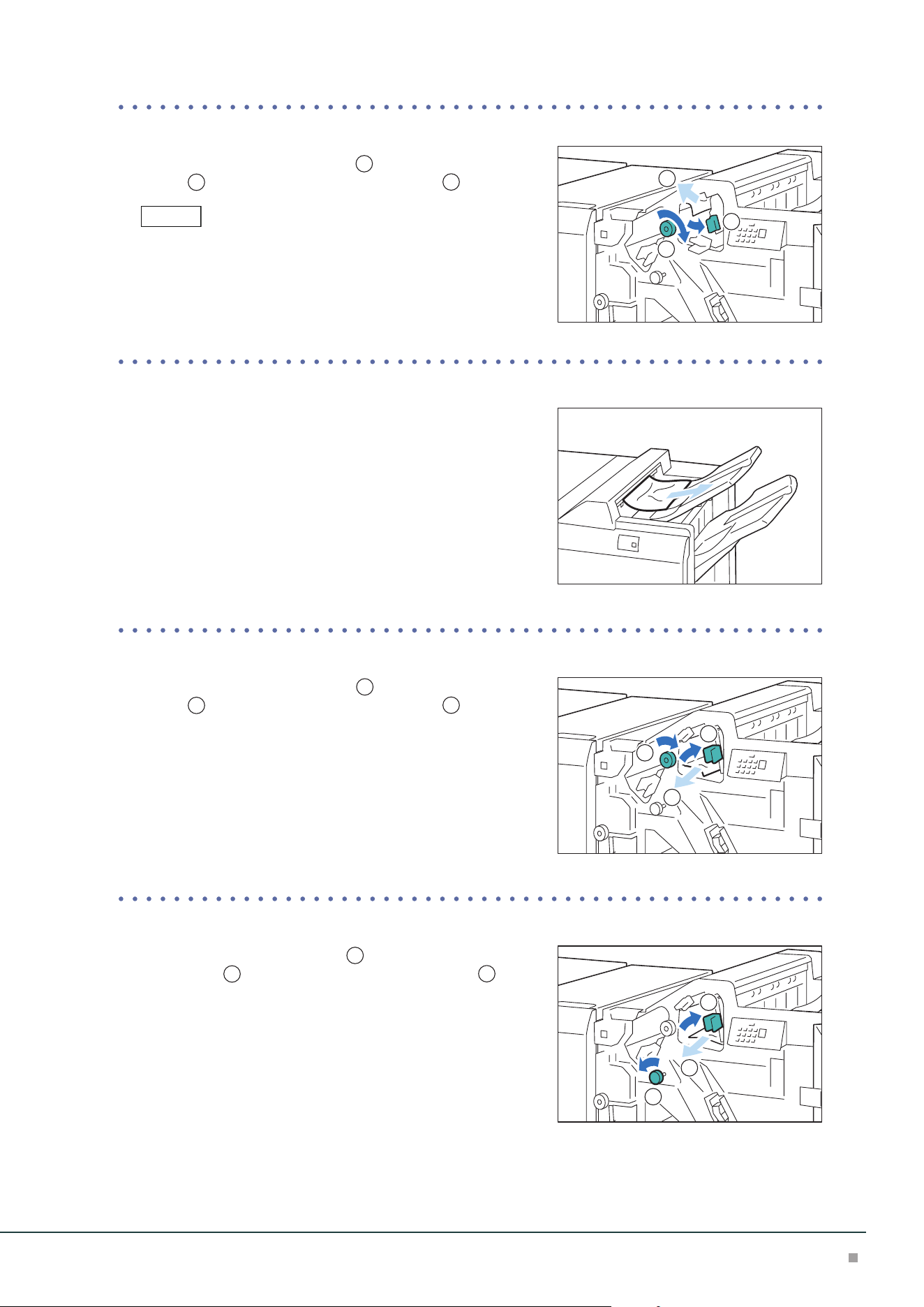
Finisher
79
■When Indicator E2 is Turned on
(1) Open lever [1c] to the right (
1
), turn knob [1e] clock-
wise (
2
), and remove the jammed paper (
3
).
Jammed paper may be hidden at the upper section.
(2) Return lever [1c].
■When Indicator E3 is Turned on
(1) Remove the jammed paper that sticks out from the exit of
the Top Output Tray.
(2) Open and close the cover.
■When Indicator E4 is Turned on
(1) Open lever [1d] to the right (
1
), turn knob [1e] clock-
wise (
2
), and remove the jammed paper (
3
).
(2) Return lever [1d].
■When Indicator E5 is Turned on
(1) Open lever [1d] to the right (
1
), turn knob [1f] counter-
clockwise (
2
), and remove the jammed paper (
3
).
(2) Return lever [1d].
Note
1
2
3
1
2
3
1
2
3
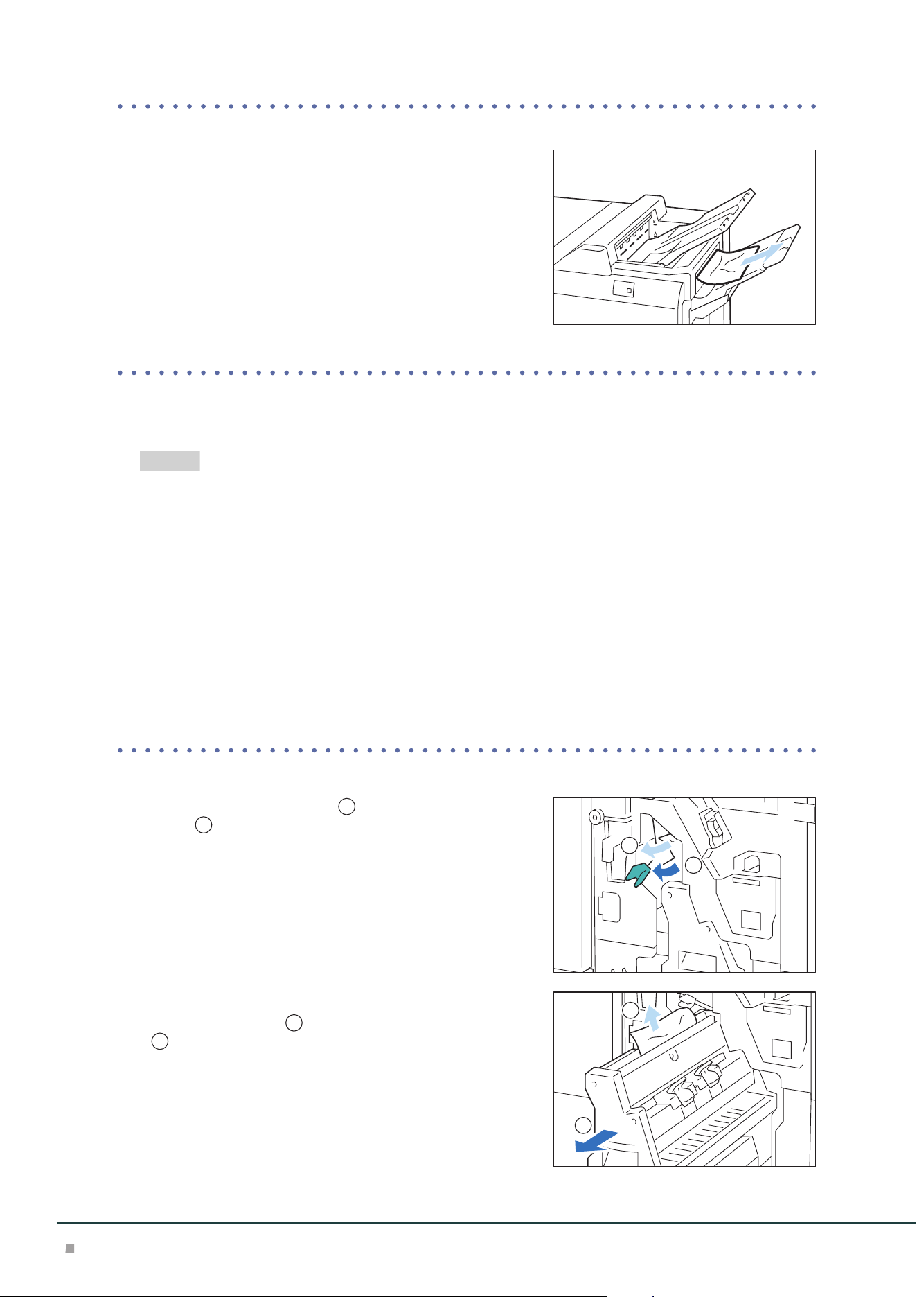
Optional Units Manual
80
■When Indicator E6 is Turned on
(1) Remove the jammed paper that sticks out from the exit of
the Finisher Tray.
(2) Open and close the cover.
3. Close the cover.
4. Check the curl direction of the jammed paper and correct the curl.
"Curl Correction" (p.36)
Booklet Maker
1. Open the Cover.
2. Remove the jammed paper.
When Indicator E7 is Turned on .................................................................................................p.80
When Indicator E8 is Turned on .................................................................................................p.81
When Indicator E9 is Turned on .................................................................................................p.81
■When Indicator E7 is Turned on
(1) Open lever [3a] to the left (
1
) and remove the jammed
paper (
2
).
(2) If you have difficulty in removing the papers, pull out
Booklet Maker [3] (
1
), and remove the jammed paper
(
2
).
(3) Return lever [3a].
(4) Push in the Booklet Maker [3].
Refer
1
2
1
2
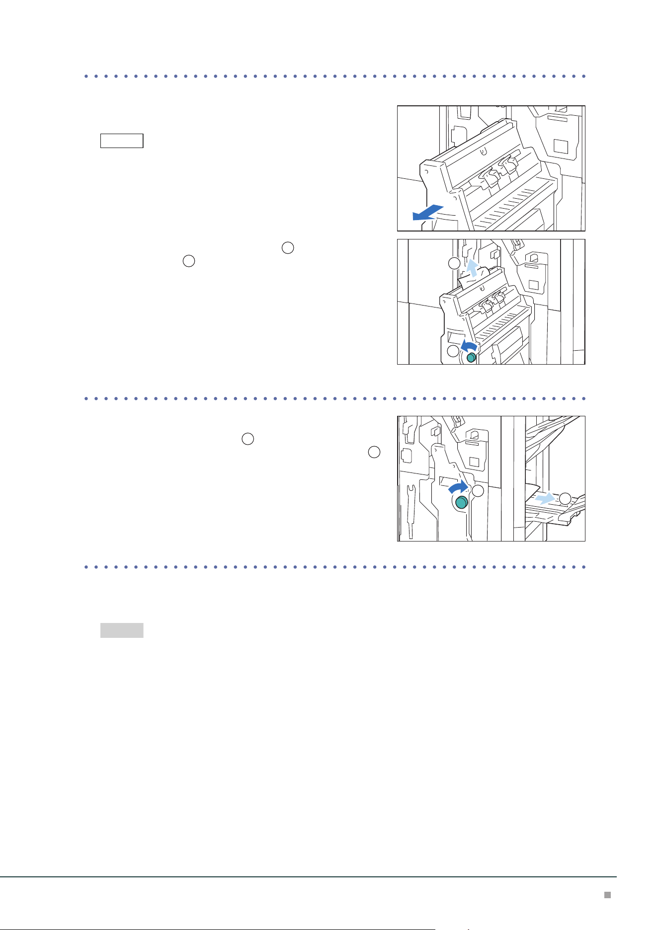
Finisher
81
■When Indicator E8 is Turned on
(1) Pull out Booklet Maker [3].
Confirm that paper is not jammed at the lever [3a] before pulling it
out.
(2) Turn knob [3b] counterclockwise (
1
) and remove the
jammed paper (
2
).
(3) Push in the Booklet Maker [3].
■When Indicator E9 is Turned on
(1) Turn knob [3b] clockwise (
1
) and remove the jammed
paper that sticks out from the exit of the Booklet Tray (
2
).
3. Close the cover.
4. Check the curl direction of the jammed paper and correct the curl.
"Curl Correction" (p.36)
Note
1
2
1
2
Refer
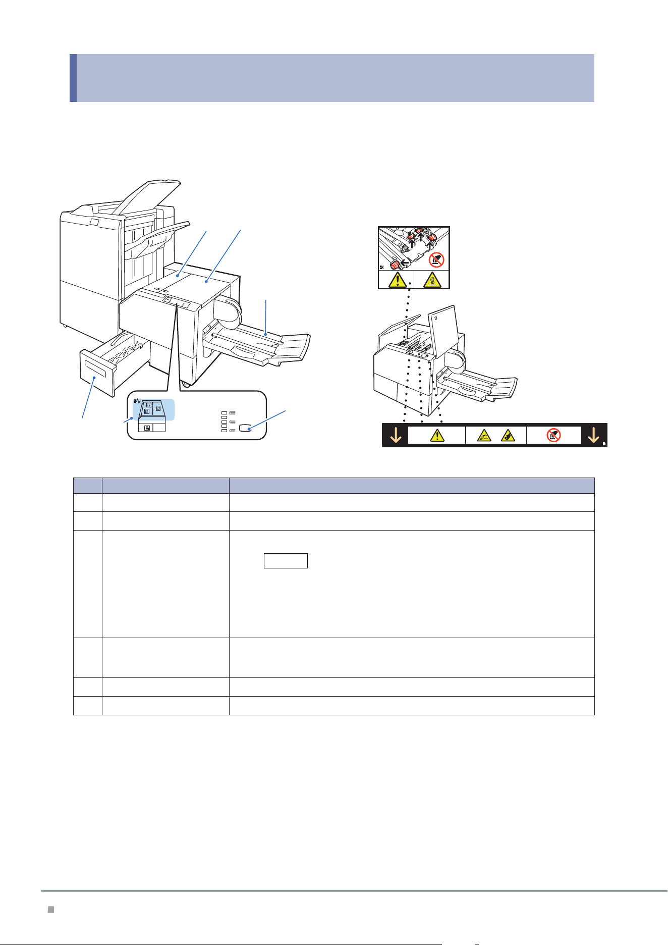
Optional Units Manual
82
10 Square Back Fold Trimmer
Device Components / Caution Labels
12
3
4
56
No. Component Function
1
Left Cover Open this cover to clear paper jams.
2
Right Cover Open this cover to clear paper jams.
3
Booklet Tray Outputs are delivered here.
When Square Back is performed, a thin press mark parallel to the back is
made. If Fore Edge Trim is performed, a thin press mark parallel to the fore
edge may be made.
In either case, a press mark becomes outstanding as a booklet becomes
thicker.
4
Back Pressing Level Button Press this button to change the roundness of the back of a saddle stitched booklet.
The higher the indicator, the higher the pressing force. The lower the indicator, the
lower the pressing force.
5
Error Indicator When paper jam occurs, the indicator is turned on.
6
Trimmer Waste Box Cut pieces go in here.
Note

Square Back Fold Trimmer
83
Main Specifications
Item Description
Paper size Same as the paper size of the Finisher Booklet Finishing.
Paper weight Same as the paper weight of the Finisher Booklet Finishing.
Booklet Tray capacity
*1
20 sets
*2
Face
Trim
Capacity
*2
Saddle Staple: 30 sheets, Single Fold: 5 sheets
Trim dimensions 2 to 20 mm
Square Back capacity
*3*4
30 sheets
Power supply AC 100-240 V +/- 10 %, 0.8 A (100 V) / 0.4 A (240 V), 50/60 Hz common
Maximum power consumption 96 W
Dimensions W 1066 x D 725 x H 552 mm
Weight 97 kg
*1: Storing may not be possible up to this value depending on your use conditions, such as of paper type.
*2: 16 sets (17-20 sheets per print), 12 sets (21-25 sheets per print), 10 sets (26-30 sheets per print).
*3: The capacity can decrease depending on type and weight of paper being used and other conditions.
*4: Square back finishing is not supported for single-folding and saddle stapling of less than 5 sheets.
Finisher with Booklet Maker is required.
Note
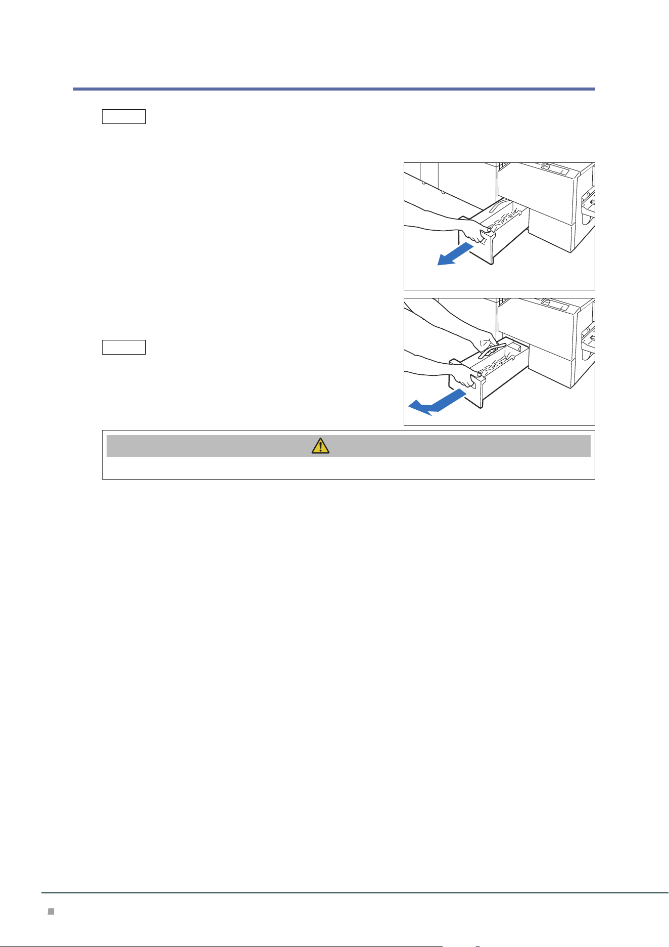
Optional Units Manual
84
Waste Container
Dispose cut pieces while the machine is on.
1. Confirm that the machine is not operating, and pull
out the waste container.
2. Hold the belt of the waste container and pull it out
with both hands.
Do not apply excessive load on the belt by twirling the container as
holding the belt, etc. Otherwise, the belt may get broken.
3. Dispose all cut pieces.
Caution
Do not collect cut pieces with hands. You may get injured with cutting edges.
4. Insert the Waste Container into the original position.
Note
Note
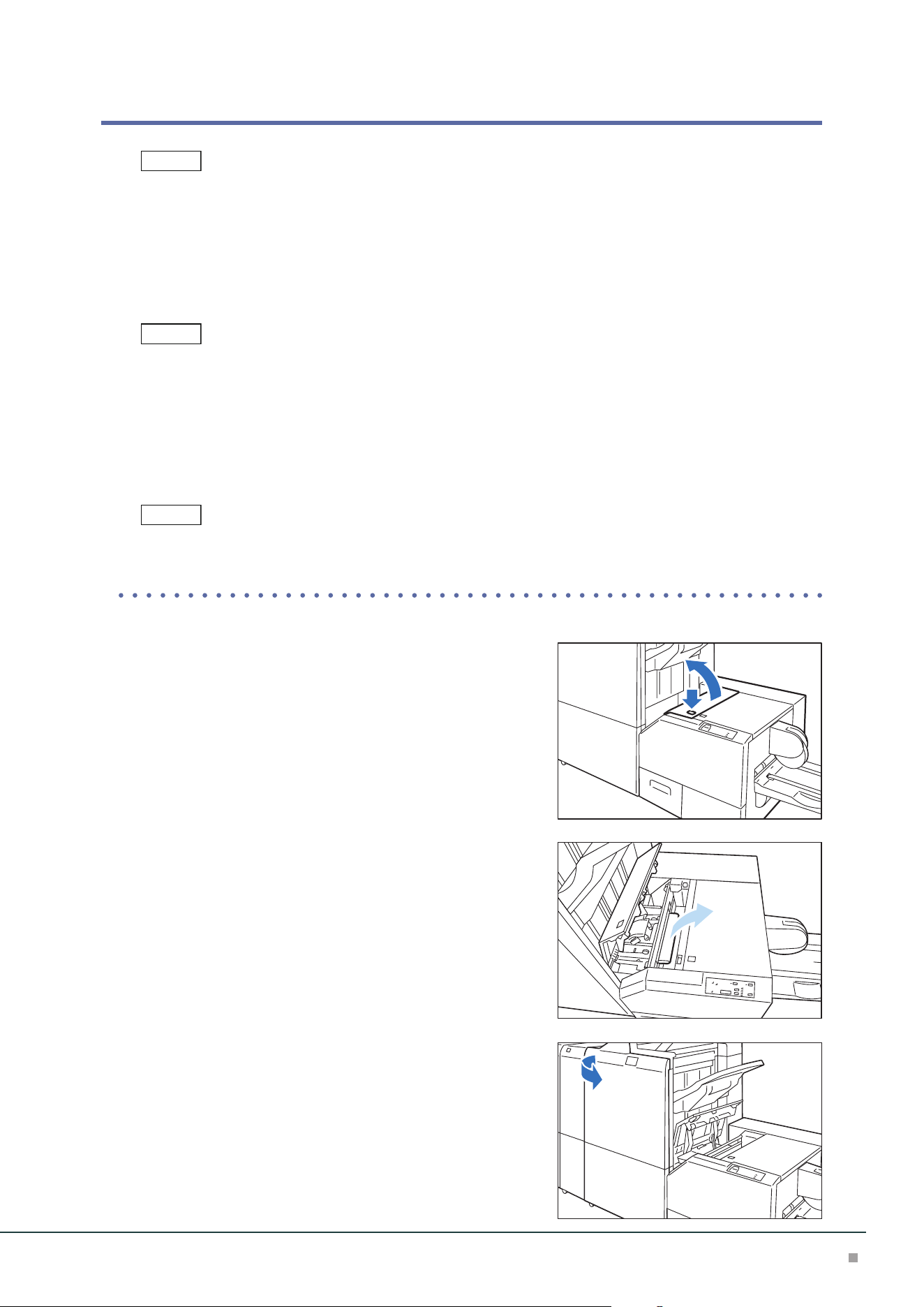
Square Back Fold Trimmer
85
Paper Jams
The error indicator at the top of the machine is turned on.
If paper is jammed, the machine stops and an alarm sounds. Follow the instructions displayed on
the screen to remove the jammed paper.
Gently remove the paper being careful not to tear it. If paper is torn while it is being removed from
the machine, remove all the torn pieces making sure that none remain inside the machine.
When you have finished clearing the paper jam, printing is resumed from the state before the pa-
per jam occurred.
Clear the paper jams while the machine is on.
1. Remove the jammed paper.
When Indicator E1 is Turned on .................................................................................................p.85
When Indicator E2 is Turned on .................................................................................................p.86
When Indicator E3 is Turned on .................................................................................................p.86
The left and Right Covers cannot be opened at the same time. Remove paper in one cover and close it. Then open
the other cover.
■When Indicator E1 is Turned on
(1) Open the Left Cover.
(2) Remove the jammed paper.
(3) If you have difficulty in removing the papers, open the
Finisher cover.
Note
Note
Note
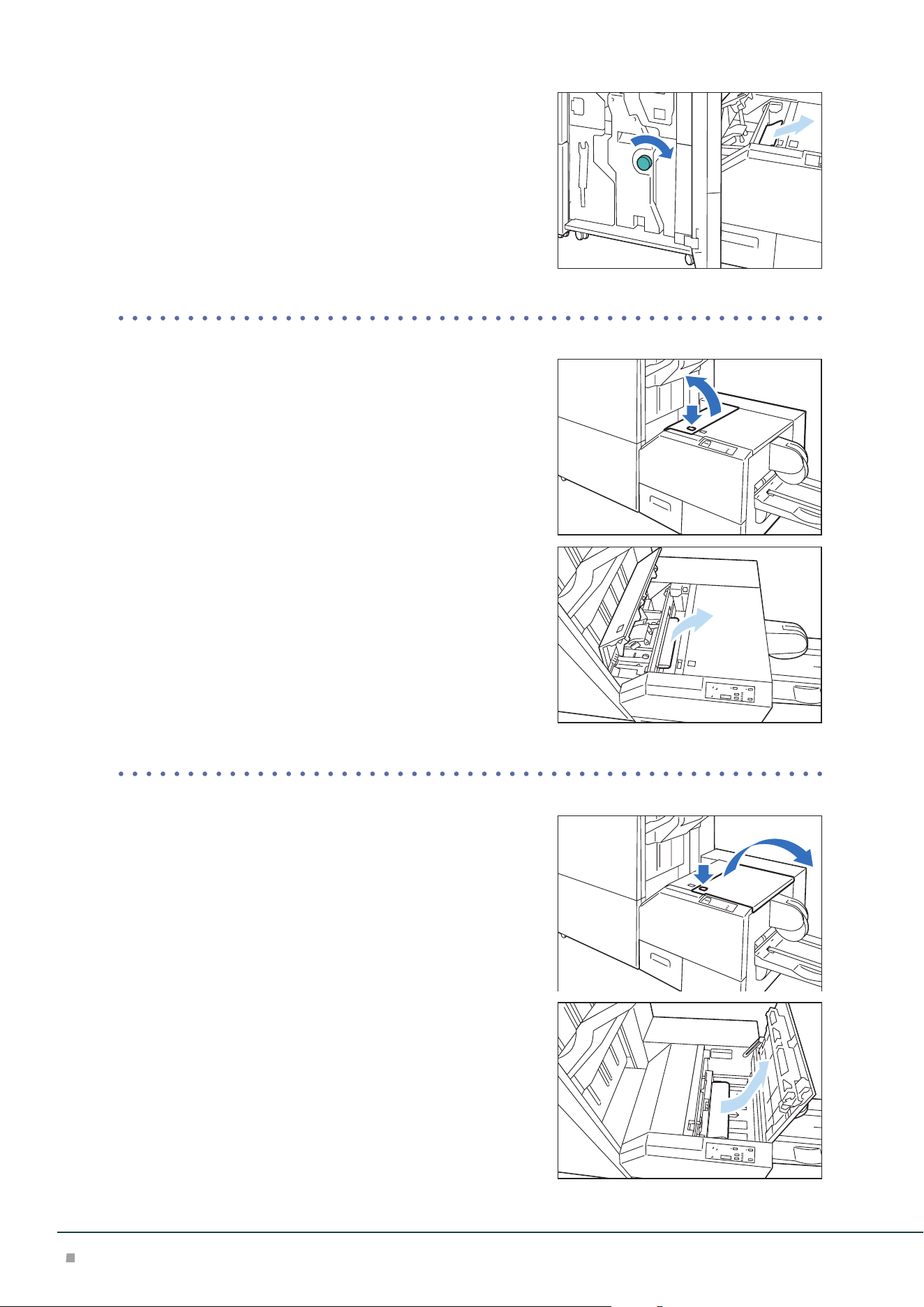
Optional Units Manual
86
(4) Turn knob [3b] clockwise and remove the paper.
(5) Close the Left Cover.
■When Indicator E2 is Turned on
(1) Open the Left Cover.
(2) Remove the jammed paper.
(3) Close the Left Cover.
■When Indicator E3 is Turned on
(1) Open the Right Cover.
(2) Remove the jammed paper.
(3) Close the Right Cover.

SHARP CORPORATION
December 2023 Edition 1
GM1876E5-1

