Installation Instructions For Self-Contained
Package Air Conditioners and Heat Pump Units
*PCH3/*PHH3 13.4 SEER2 “H” SERIES With R-410A
IOG-3022B
06/2022
19001 Kermier Rd. Waller, TX 77484
www.goodmanmfg.com • www.amana-hac.com
© 2021-2022 Daikin Comfort Technologies Manufacturing, L.P.
is a registered trademark of Maytag Corporation or its related companies and is used under license. All rights reserved.
Only personnel that have been trained to install, adjust,
service or repair(hereinafter, “service”) the equipment spec-
ified in this manual should service the equipment. The manu-
facturer will not be responsible for any injury or property
damage arising from improper service or service proce-
dures. If you service this unit, you assume responsibility for
any injury or property damage which may result. In addition,
in jurisdictions that require one or more licenses to service
the equipment specified in this manual, only licensed per-
sonnel should service the equipment. Improper installation,
adjustment, servicing or repair of the equipment specified
in this manual, or attempting to install, adjust, service or
repair the equipment specified in this manual without proper
training may result in product damage, property damage,
personal injury or death.
WARNING
RECOGNIZE THIS SYMBOL AS
A SAFETY PRECAUTION.
All information contained herein is subject to change without notice.
These installation instructions cover the outdoor installation
of self contained package air conditioner and heating units.
See the Specication Sheets applicable to your model for
information regarding accessories.
*NOTE: Please contact your distributor or our
website for the applicable Specification Sheets
referred to in this manual.
TABLE OF CONTENTS
TO THE INSTALLER .........................................................2
SHIPPING INSPECTION ...................................................2
Checking Product Received ....................................2
Message to the Homeowner ....................................2
REPLACEMENT PARTS ...................................................2
Ordering Parts ..........................................................2
IMPORTANT SAFETY INSTRUCTIONS ...........................3
Recognize Safety Symbols, Words, and Labels . 3
CODES AND REGULATIONS .........................................3
General .......................................................................3
EPA Regulations .............................................................3
National Codes ...............................................................3
MAJOR COMPONENTS ....................................................4
General .......................................................................4
INSTALLATION ..................................................................4
Pre-Installation Checkpoints .................................4
Clearance ...................................................................4
Location.......................................................................4
Outside Slab Installation (Figure 1) .....................4
Rooftop Installation (Figure 2) ..............................4
RIGGING ...........................................................................5
Rigging Details ..........................................................5
DUCTING ..........................................................................5
Connecting the Return and Supply
Flexible Duct in Manufactured or
Modular Housing Application .............................6
Plenum Application ...................................................6
Filters ..........................................................................6
PIPING ...............................................................................6
Condensate Drain ......................................................6
Do not bypass safety devices.
WARNING

2
ELECTRICAL WIRING ....................................................6
High Voltage Wiring ..................................................7
Low Voltage Wiring ..................................................7
Internal Wiring:.........................................................8
OPERATION ......................................................................8
Start-Up Procedure and Checklist ......................8
Heat Pump Start-Up Procedure ............................8
Final System Checks ...............................................9
COMPONENTS ................................................................9
Contactor ........................................................................9
Crankcase Heater .....................................................9
Condenser Motor ......................................................9
Compressor ................................................................9
Contactor Relay ........................................................9
Defrost Control .......................................................9
Outdoor Thermostat ................................................9
Reversing Valve Coil ................................................9
Indoor Blower Motor ..............................................9
Blower Interlock Relay ..........................................9
EXPLANATION AND GUIDANCE (HEAT PUMP) .............9
HEAT PUMP REFRIGERANT CIRCUIT - Figure 8 . 10
DEFROST CONTROL ......................................................10
SUGGESTED FIELD TESTING/TROUBLESHOOTING . 10
Testing Thermostat Control ................................10
Testing Defrost Thermostat ................................. 11
AIR FLOW MEASUREMENT AND ADJUSTMENT .... 11
Total External Static Pressure ................................ 11
ADJUSTING SPEED TAP FOR
INDOOR BLOWER MOTOR .....................................12
EEM Motor ................................................................12
EEM Motor Speed Adjustment ..............................12
ECM Motor ................................................................12
ECM Motor Speed Adjustment ..............................12
DIP Switch Functions ..............................................12
Refrigerant Charge Check
(Units with Fixed Orifice Devices) ........................13
Expansion Valve (TXV) System ...............................13
ELECTRIC HEAT INSTALLATION ..................................14
Heater Kit ..................................................................14
MAINTENANCE ...............................................................15
SERVICE .........................................................................15
Inadequate Air Volume Through Indoor Coil ...15
Outside Air Into Return Duct ..............................15
Undercharge ...........................................................15
Poor “Terminating” Sensor Contact .................15
Malfunctioning Reversing Valve .........................16
BLOWER PERFORMANCE *P*H 13.4 SEER2 ............17
DIP SWITCH FUNCTION SELECTION ........................18
TROUBLESHOOTING CHART .......................................20
UNIT DIMENSIONS .........................................................21
START-UP CHECKLIST ..................................................24
To The Installer
Carefully read all instructions for the installation prior
to installing unit. Make sure each step or procedure is
understood and any special considerations are taken into
account before starting installation. Assemble all tools,
hardware and supplies needed to complete the installation.
Some items may need to be purchased locally. After
deciding where to install unit, closely look the location
over - both the inside and outside of home. Note any
potential obstacles or problems that might be encountered
as noted in this manual. Choose a more suitable location if
necessary.
IMPORTANT NOTE: If a crankcase heater is used,
the unit should be energized 24 hours prior
to compressor start up to ensure crankcase
heater has sufficiently warmed the compressor.
Compressor damage may occur if this step is not
followed.
Before using this manual, check the serial plate for proper
model identication.
The installation and servicing of this equipment must be
performed by qualied, experienced technicians only.
SHIPPING INSPECTION
Checking Product Received
Upon receiving the unit, inspect it for damage from
shipment. Claims for damage, either shipping or
concealed, should be led immediately with the shipping
company. Check the unit model number, specications,
electrical characteristics and accessories to determine if
they are correct. In the event an incorrect unit is shipped,
it must be returned to the supplier and must NOT be
installed. The manufacturer assumes no responsibility for
installation of incorrectly shipped units.
Message to the Homeowner
These instructions are addressed primarily to the installer;
however, useful maintenance information is included and
should be kept, after installation, for future reference.
REPLACEMENT PARTS
Ordering Parts
When reporting shortages or damages, or ordering repair
parts, give the complete unit model and serial numbers
as stamped on the unit’s nameplate. Replacement parts
for this appliance are available through your contractor or
local distributor. For the location of your nearest distributor,
consult the white business pages, the yellow page section
of the local telephone book or contact:
HOMEOWNER SUPPORT
DAIKIN COMFORT TECHNOLOGIES
MANUFACTURING, L.P.
19001 KERMIER ROAD WALLER, TEXAS 77484
855-770-5678
3
IMPORTANT SAFETY INSTRUCTIONS
Recognize Safety Symbols, Words, and Labels
The following symbols and labels are used throughout this
manual to indicate immediate or potential hazards. It is the
owner’s responsibility to read and comply with all safety
information and instructions accompanying these symbols.
Failure to heed safety information increases the risk of
serious personal injury or death, property damage and/or
product damage.
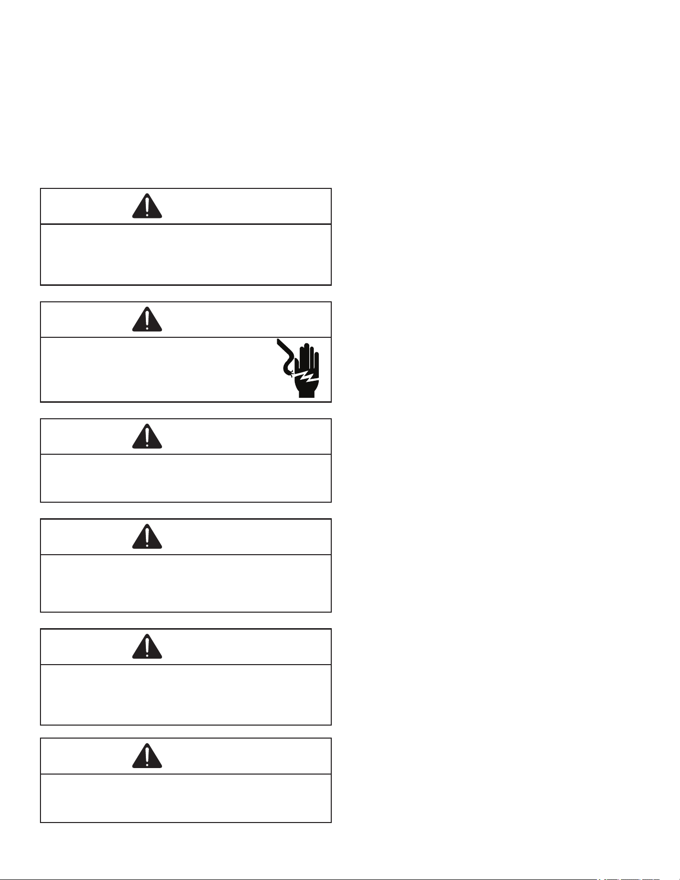
WARNING
Do not connect to or use any device that is not design cer-
tified by the manufacturer for use with this unit. Serious
property damage, personal injury, reduced unit perfor-
mance and/or hazardous conditions may result from the use
of such non-approved devices.
WARNING
HIGH VOLTAGE!
Disconnect all power before servicing or in-
stalling this unit. Multiple power sources may
be present. Failure to do so may cause proper-
ty damage, personal injury or death.
WARNING
Connecting unit duct work to unauthorized heat producing
devices such as a fireplace insert, stove, etc. may result in
property damage, fire, carbon monoxide poisoning, explo-
sion, personal injury or death.
WARNING
To avoid property damage, personal injury or death, do not
use this unit if any part has been under water. Immediately
call a qualified service technician to inspect the furnace
and to replace any part of the control system and any gas
control having been under water.
WARNING
This unit must not be used as a “construction heater” during
the finishing phases of construction on a new structure.
This type of use may result in premature failure of the unit
due to extremely low return air temperature and exposure
to corrosive or very dirty atmospheres.
WARNING
To prevent the risk of property damage, personal injury, or
death, do not store combustible materials or use gasoline
or other flammable liquids or vapors in the vicinity of this
appliance.
CODES AND REGULATIONS
General
The *PCH3 & *PHH3 series air conditioners and heat
pumps are designed for OUTDOOR USE ONLY. This
series is available in cooling Capacities of 2, 2 ½, 3, 3 ½,
4 and 5 nominal tons of cooling. Optional eld installed
heat kits are available in 5,8,10,15 and 20 KW. The units
can be easily installed in manufactured or modular homes
with existing high-static duct work. The units can also be
easily converted to accommodate a plenum for normal
or low-static applications. The *PCH3 & *PHH series are
self contained packaged units so the only connections
needed for installation are the supply and return ducts, the
line and low voltage wiring and drain connection. Rated
performance is achieved after 20 hours of operation. Rated
performance is delivered at the specied airow. See
outdoor unit specication sheet for split system models
or product specication sheet for packaged and light
commercial models. Specication sheets can be found at
www.goodmanmfg.com for Goodman® brand products or
www.amana-hac.com for Amana® brand products. Within
either website, please select the residential or commercial
products menu and then select the submenu for the type
of product to be installed, such as air conditioners or heat
pumps, to access a list of product pages that each contain
links to that model’s specication sheet.
The information on the rating plate is in compliance with
the FTC & DOE rating for single phase units. The three
phase units in this series are not covered under the DOE
certied program. The eciency ratings of these units are a
product of thermal eciency determined under continuous
operating conditions independent of any installed system.
EPA Regulations
Important: The United States Environmental
Protection Agency (EPA) has issued various
regulations regarding the introduction and
disposal of refrigerants in this unit. Failure
to follow these regulations may harm the
environment and can lead to the imposition of
substantial fines. Because regulations may vary
due to passage of new laws, we suggest a certified
technician perform any work done on this unit.
Should you have any questions please contact the
local office of the EPA.
National Codes
This product is designed and manufactured to permit
installation in accordance with National Codes. It is the
installer’s responsibility to install the product in accordance
with National Codes and/or prevailing local codes and
regulations.
4
MAJOR COMPONENTS
General
The unit includes a hermetically sealed refrigerating system
(consisting of a compressor, condenser coil, evaporator
coil with owrator), an indoor blower, a condenser fan and
all necessary internal electrical wiring. The heat pump also
includes a reversing valve, solenoid, defrost thermostat
and control and loss of charge protection. The system
is factory-evacuated, charged and performance tested.
Refrigerant amount and type are indicated on rating plate.
INSTALLATION
Pre-Installation Checkpoints
Before attempting any installation, the following points
should be considered:
• Structural strength of supporting members
• Clearances and provision for servicing
• Power supply and wiring
• Air duct connections
• Drain facilities and connections
• Location may be on any four sides of a home,
manufactured or modular, to minimize noise
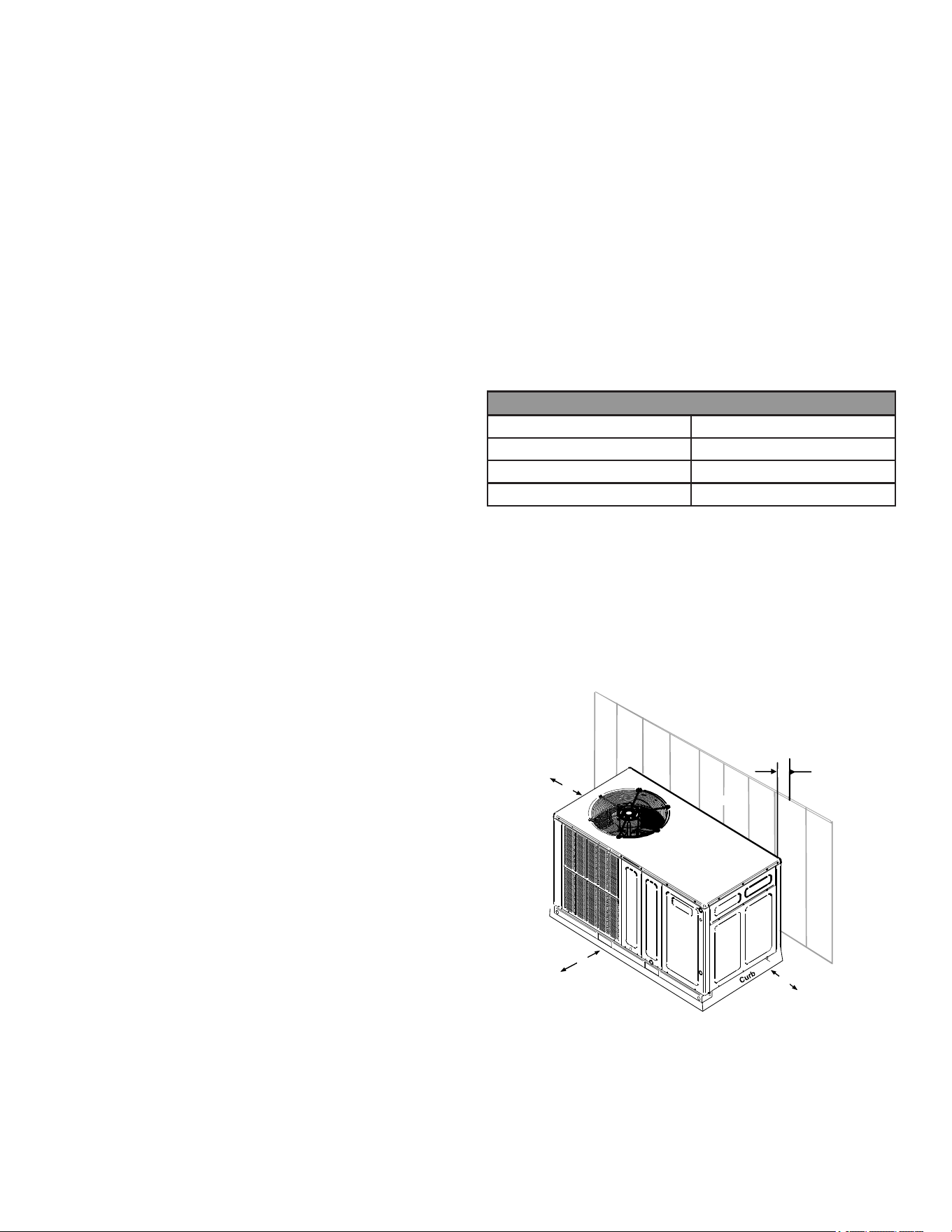
Clearance
The unit is designed to be located outside the building
with unobstructed condenser air inlet and discharge.
Additionally, the unit must be situated to permit access
for service and installation. Condenser air enters from
three sides. Air discharges upward from the top of the
unit. Refrigerant gauge connections are made on the right
side of the unit as you face the compressor compartment.
Electrical connections can be made either on the right
or left sides of the unit. The best and most common
application is for the unit to be located 10” from wall (4”
minimum) with the connection side facing the wall. This
“close to the wall” application minimizes exposed wiring.
Close to the wall application assures free, unobstructed
air to the other two sides. In more conned application
spaces, such as corners provide a minimum 12” clearance
on all air inlet sides. Allow 36” minimum for service access
to the compressor compartment and controls. The top of
the unit should be completely unobstructed. If units are to
be located under an overhang, there should be a minimum
of 48” clearance and provisions made to deect the warm
discharge air out from the overhang.
Location
Consider the eect of outdoor fan noise on conditioned
space and any adjacent occupied space. It is
recommended that the unit be placed so that condenser air
discharge does not blow toward windows less than 25 feet
away.
The unit should be set on a solid, level foundation -
preferably a concrete slab at least 4 inches thick. The
slab should be above ground level and surrounded by
a graveled area for good drainage. Any slab used as a
unit’s foundation should not adjoin the building as it is
possible that sound and vibration may be transmitted to
the structure. For rooftop installation, steel or treated wood
beams should be used as unit support for load distribution.
Heat pumps require special location consideration in areas
of heavy snow accumulation and/or areas with prolonged
continuous subfreezing temperatures. Heat pump unit
bases have holes under the outdoor coil to permit drainage
of defrost water accumulation. The unit must be situated
to permit free unobstructed drainage of the defrost water
and ice. A minimum 2” clearance under the outdoor coil is
required in the milder climates.
Heat Pump Elevation Chart
Design Temperature Suggested Minimum Elevation
+15° and above 2 - 1/2”
-5° to +14 ° 8”
Below -5° 12”
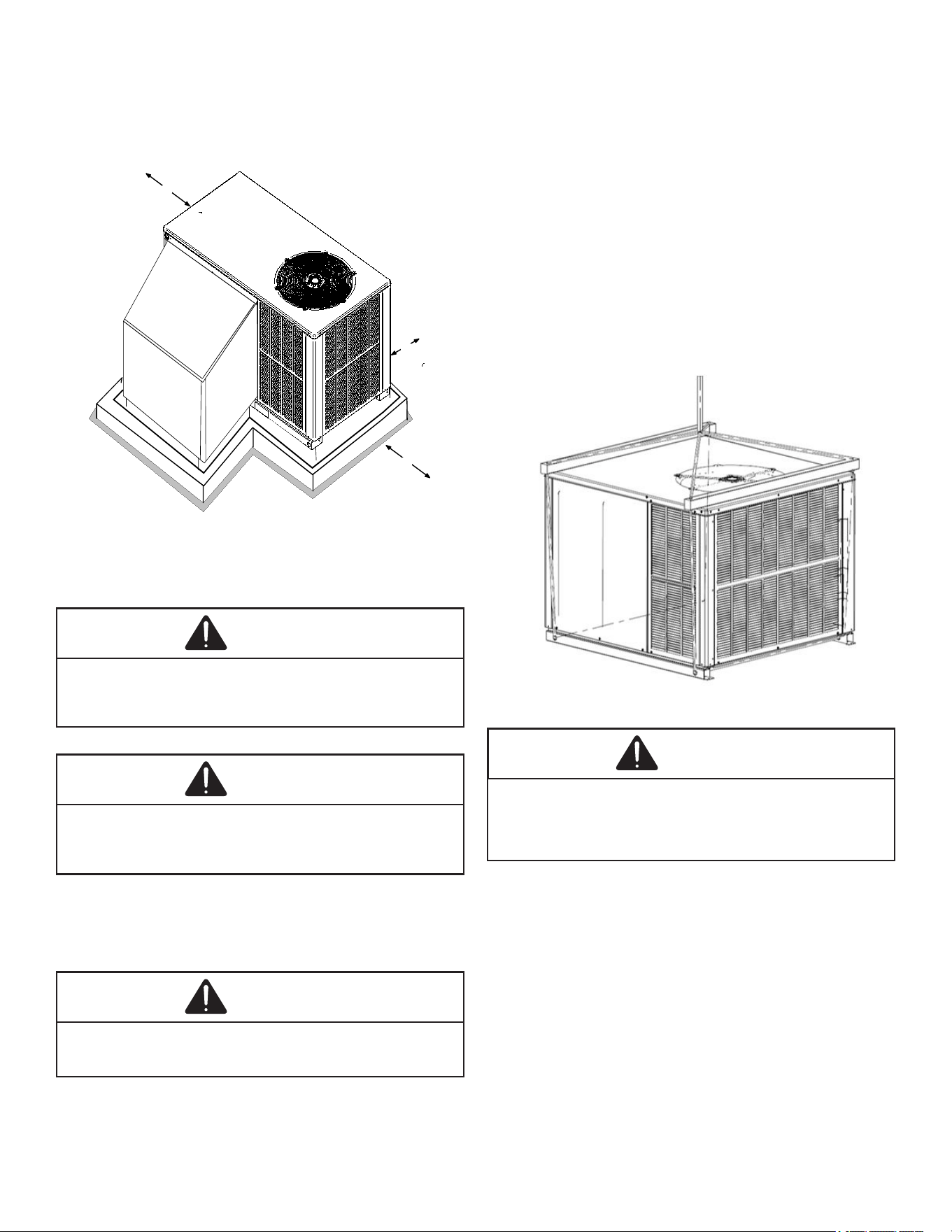
Outside Slab Installation (Figure 1)
1. The unit must be mounted on a solid, level foundation.
2. Select a location that will minimize the length of the
supply and return ducts.
3. Select a location where external water drainage
cannot collect around the unit.
4. Consideration should also be given to shade,
appearance and noise.
36"
36"
10"
UNIT
WALL
36"
Figure 1
Rooftop Installation (Figure 2)
1. Before locating the unit on the roof, make sure that
the strength of the roof and beams is adequate to
support the weight involved. (See specication sheet
for weight of units.) This is very important and the
installer’s responsibility.
5
2. Make proper consideration for the weather-tight
integrity of the roof and proper drainage of condensate.
3. To ensure proper condensate drainage, unit must be
installed in a level position.
4. Consideration should also be given to shade,
appearance and noise.
36"
36"
24"
PLENUM
UNIT
PLATFORM
CURB
Figure 2
RIGGING
Rigging Details
WARNING
To prevent property damage, the unit should remain in an
uprght position during all rigging and moving operations. To
facilitate lifting and moving when a crane is used, place the
unit in an adequate cable sling.
CAUTION
If units are lifted two at a time, the fork holes on the
condenser end of the unit must not be used. Minimum fork
length is 42” to prevent damage to the unit; however, 48” is
recommended.
NOTE: Provisions for forks have been included in
the unit base frame. No other fork locations are
approved.
WARNING
To prevent possible equipment damage, property damage, per-
sonal injury or death, the following bullet points must be
observed when installing the unit.
Unit must be lifted by the four lifting holes located at the
base frame corners.
• Lifting cables should be attached to the unit with
shackles.
• The distance between the crane hook and the top of
the unit must not be less than 60”.
• Two spreader bars must span over the unit to prevent
damage to the cabinet by the lift cables. Spreader
bars must be of sucient length so that cables do
not come in contact with the unit during transport.
Remove wood struts mounted beneath unit base
frame before setting unit on roof curb. These struts
are intended to protect unit base frame from fork lift
damage. Removal is accomplished by extracting the
sheet metal retainers and pulling the struts through
the base of the unit. Refer to rigging label on the unit.
Refer to the Roof Curb Installation Instructions for proper
curb installation. Curbing must be installed in compliance
with the National Roong Contractors Association Manual.
Figure 3
WARNING
Do not, under any circumstances, connect return ductwork
to any other heat producing devices such as a fireplace
insert, stove, etc. Unauthorized use of such devices may
result in property damage, fire, carbon monoxide poisoning,
explosion, personal injury or death.
DUCTING
Ducting work should be fabricated by the installing
contractor in accordance with local codes. Industry
manuals may be used as a guide when sizing and
designing the duct system- such as NESCA (National
Environmental Systems Contractors Association, 1501
Wilson Blvd., Arlington, Virginia 22209).
The unit should be placed as close as possible to the
space to be air-conditioned allowing clearance dimensions
as indicated. Ducts should run as directly as possible
to supply and return outlets. Use of non-ammable
6
weatherproof exible connectors on both supply and return
connections at the unit to reduce noise transmission is
recommended.
It is preferable to install the unit on the roof of the structure
if the registers or diusers are located in the wall or ceiling.
A slab installation is recommended when the registers are
low on the wall or in the oor.
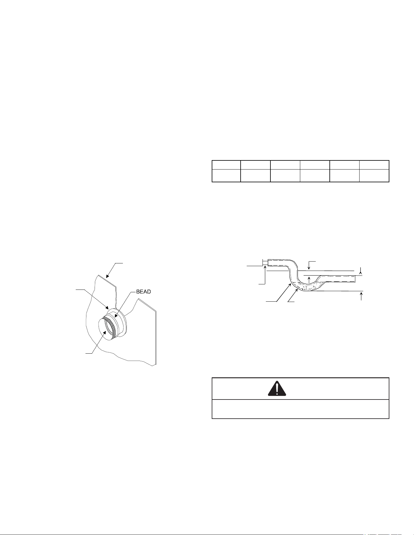
Connecting the Return and Supply Flexible Duct in
Manufactured or Modular Housing Application
The return and supply ttings are to be attached at
the unit to a suitable square to round duct converter.
Your distributor has a factory designed square to round
converter transition. The model #’s of these kits are
as follows: Small Chassis 27.5” SQRPCH102, Large
and Extra Large Chassis 32.5:” and 36” SQRPCH103
(See Specication Sheets for Dimension details). The
SQRPCH101 has 14” duct collar on supply and 16” duct
collar (equivalent diameter, opening is oval) on the return.
The SQRPCH102 and SQRPCH103 have 14” duct collar
on supply and 18” duct collar (equivalent diameter, opening
is oval) on the return. The collars are to be slipped into the
openings, and the anges bent around the converter. The
square to round converter is attached to the anges of the
square duct openings. The exible duct is then clamped on
to the collars. Once the duct is axed to the unit, seal the
collars and anges with a proper waterproof sealant
(See Figure 4).
OUTER FLANGE
STARTER FLANGE
SQUARE TO ROUND
DUCT CONVERTER PANEL
Figure 4
It is strongly encouraged to use appropriately sized ducts
based upon the CFM for your application (unit’s CFM). If
duct sizing through industry manuals or air duct calculators
require larger ducts than converter openings, run larger
duct size up to unit converter openings and reduce with a
reducer duct tting or transition right at the unit.
Plenum Application
A suitable plenum or square duct must be constructed. The
duct cross-sectional area should be determined by industry
duct sizing manuals or air duct calculators.
On ductwork exposed to outside air conditions of
temperature and humidity, use an insulation with a good
K factor, and a vapor barrier. Industry practices should be
followed. Balancing dampers are recommended for each
branch duct in the supply system. Ductwork should be
properly supported from the unit.
NOTE: Proper sealing of all duct work and air
handling compartments is extremely important to
overall unit efficiency.
Filters
Filters are not provided with unit, and must be supplied
and installed in the return duct system by the installer.
A eld installed lter grille is recommended for easy and
convenient access to the lters for periodic inspection
and cleaning. Filters must have adequate face area
for the rated quantity of the unit. See table below for
recommended lter size.
Unit 2 Ton 2 1/2 Ton 3 Ton 3 1/2 4 Ton 5 Ton
Min. Filter
Size
(1)20 x 20 x 1 (1)20 x 25 x 1 (1)25 x 25 x 1 (2)20 x 20 x 1 2(20) x 25 x1
Recommended filter sizes
Table 1
PIPING
Condensate Drain
The condensate drain connection of the evaporator is a
half coupling of ¾” N.P.T. A trap must be provided to have
Proper condensate drainage.
2" Minimum
3" Minimum
A Positive Liquid Seal
Is Required
Flexible
Tubing-Hose
Or Pipe
Drain
Connection
Unit
Figure 5
Install condensate drain trap as shown. Use ¾” drain
connection size or larger. Do not operate without trap. Unit
must be level or slightly inclined toward drain.
ELECTRICAL WIRING
CAUTION
To avoid property damage or personal injury due to fire, use
only copper conductors.
All wiring should be made in accordance with the National
Electrical Code. The local Power Company should
be consulted to determine the availability of sucient
power to operate the unit. The voltage, frequency, and
phase at the power supply should be checked to make
sure it corresponds to the unit’s RATED VOLTAGE
REQUIREMENT.
7
Install a branch circuit fused disconnect near the unit, in
accordance with the N.E.C. or local codes. Wire sizes and
overcurrent protection should be determined from the unit
nameplate ampacity and in accordance with Table 2 (page
7) or the N.E.C. Under no circumstances should wiring be
sized smaller than is recommended by either of these two
sources.
Fuses smaller than that recommended on the wiring
diagrams could result in unnecessary fuse failure or
service calls. The use of protective devices of larger size
than indicated could result in extensive damage to the
equipment. The manufacturer bears no responsibility for
damage caused to equipment as result of the use of larger
than is recommended size protective devices.
All units have undergone a run test prior to packaging for
shipment. This equipment has been started at minimum
rated voltage and checked for satisfactory operation. Do
not attempt to operate this unit if the voltage is not within
the minimum and maximum voltages shown on nameplate.
The units are designed for operation on 60 hertz current
and at voltages as shown on the rating plate. All internal
wiring in the unit is complete. It is necessary to bring in the
power supply to the contactor as shown on the unit wiring
diagram which is supplied with each unit. The low voltage
wiring must be connected between the unit control panel
and the room thermostat.
All exterior wiring must be within approved weatherproof
conduit. The unit must be permanently grounded in
accordance with local codes, or in absence of local codes,
with N.E.C ANSI/ NFPA NO. 70-1984 or latest edition by
using ground lug in the control box.
DO NOT EXCEED THE MAXIMUM OVERCURRENT
DEVICE SIZE SHOWN ON UNIT DATA PLATE.
Fuses or HACR type circuit breakers may be used
where codes permit.
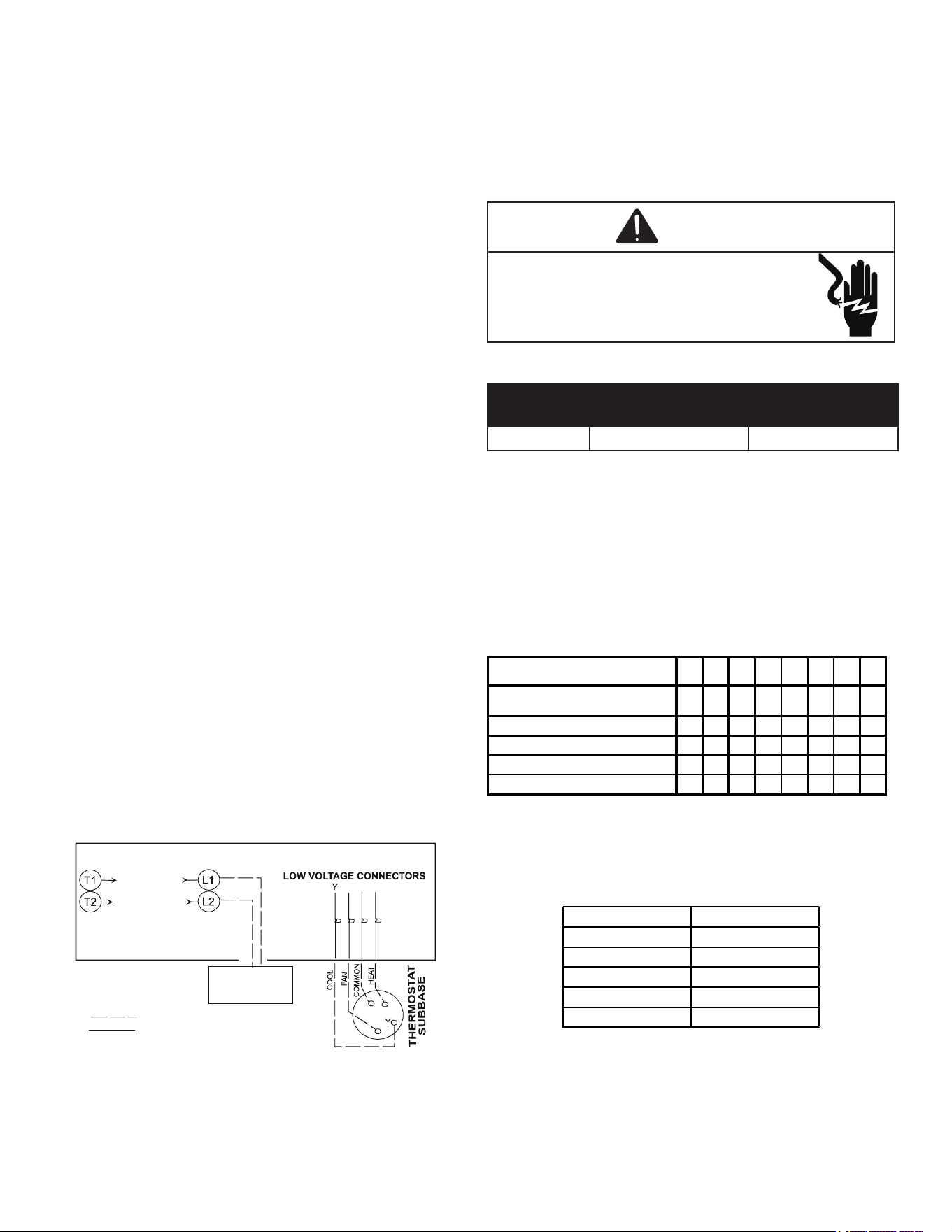
CONTACTOR
R
W
G
G
R W
FOR INTERNAL WIRING SEE WIRING LABEL ATTACHED TO UNIT
24 VOLT CONTROL WIRING
LINE VOLTAGE
DISCONNECT
SWITCH
LINE VOLTAGE POWER WIRING
Figure 6
NOTE: Units are equipped with a single pole
contactor. Caution must be exercised when
servicing as only one leg of the power supply is
broken with the contactor.
To wire the unit, make the following high and low voltage
connections.
WARNING
HIGH VOLTAGE!
Disconnect all power before servicing or in-
stalling this unit. Multiple power sources may
be present. Failure to do so may cause proper-
ty damage, personal injury or death.
High Voltage Wiring: (See Figure 7)
Rated
Voltage
Minimum Supply
Voltage
Maximum Supply
Voltage
208/230V 197 253
Unit Voltage
NOTE: The unit transformer is factory connected
for 240V operation. If the unit is to operate on
208V, reconnect the transformer primary lead as
shown on the unit wiring diagram.
Connect incoming power leads to terminals L1 & L2 on
contactor in the electrical control section, using wire sizes
specied in wiring table.
BRANCH CIRCUIT AMPACITY
15
20
25
30
35
40
45
50
SUPPLY WIRE LENGTH - FEET
200
6
4
4
4
3
3
2
2
150
8
6
6
4
4
4 3 3
100 10 8 8 6 6 6 4 4
50 14 12 10 10 8 8 6 6
Table 2
Low Voltage Wiring:
a. Air Conditioners - Connect 24V wires from the
thermostat to the corresponding wires in the
control box using No. 18AWG as follows:
LEAD THERMOSTAT
Red R (24V)
Green G (Fan)
Yellow Y (Cool)
White W1 (Heat)*
Brown W2 (Heat)*
Table 3
b. Heat Pumps - Connect 24V wires from the
thermostat to the corresponding wires in the
control box using No. 18AWG as follows:
8
TERMINAL THERMOSTAT
Red R (24V)
Green G (Fan)
Orange O (Rev. Valve)
White W1 (Heat, 2nd)*
Brown W2 (Heat 3rd)*
Yellow Y (Cool)
C (Blue) C (Common)
*Optional field installed heat connections
Table 4
Internal Wiring:
A diagram detailing the internal wiring of this unit is located
on the electrical box cover. If any of the original wire
supplied with the appliance must be replaced, the wire
gauge and insulation must be the same as the original
wiring.
1. For branch circuit wiring (main power supply to unit
disconnect), the minimum wire size for the length of
the run can be determined from Table 2 using the
circuit ampacity found on the unit rating plate. From
the unit disconnect to unit, the smallest wire size
allowable in Table 4 may be used for the ampacity, as
the Disconnect must be in sight of the unit.
2. Wire size based on 60°C rated wire insulation and 30°
C Ambient Temperature (86°F).
3. For more than 3 conductors in a raceway or cable,
see the N.E.C. for derating the ampacity of each
conductor.
OPERATION
Start-Up Procedure and Checklist
Begin with power turned o at all disconnects.
WARNING
HIGH VOLTAGE!
Disconnect all power before servicing or in-
stalling this unit. Multiple power sources may
be present. Failure to do so may cause proper-
ty damage, personal injury or death.
Air Conditioner Start-up Procedure
1. Turn thermostat system switch to “Cool,” and fan-
switch to “Auto” and turn temperature setting as high
as it will go.
2. Inspect all registers and set them to the normal open
position.
3. Turn on the electrical supply at the disconnect.
4. Turn the fan switch to the “ON” position. The blower
should operate after a 10 second delay.
5. Turn the fan switch to “Auto” position. The blower
should stop after a 60 second delay.
6. Slowly lower the cooling temperature until the unit
starts. The compressor, blower and fan should now be
operating. Allow the unit to run 10 minutes, make sure
cool air is being supplied by the unit.
7. Turn the temperature setting to the highest position,
stopping the unit. The indoor blower will continue to
run for 60 seconds.
8. Turn the thermostat system switch to “OFF” and
disconnect all power when servicing the unit.
WARNING
HIGH VOLTAGE!
Disconnect all power before servicing or in-
stalling this unit. Multiple power sources may
be present. Failure to do so may cause proper-
ty damage, personal injury or death.
Heat Pump Start-Up Procedure
1. Check the cooling mode for the heat pump in the
same manner as above. The reversing valve is
energized when the thermostat is placed in the
cooling position. A clicking sound should be noticeable
from the reversing valve. By lowering the temperature
setting to call for cooling, the contractor is energized.
The compressor, blower and fan should then be
running. After the cooling mode is checked out, turn
the thermostat system switch to “OFF”.
2. Turn the thermostat system switch to “HEAT” and fan
switch to “AUTO”.
3. Slowly raise the heating temperature setting. When
the heating rst stage makes contact, stop raising
the temperature setting. The compressor, blower and
fan should now be running with the reversing valve in
the de-energized (heating) position. After giving the
unit time to settle out, make sure the unit is supplying
heated air.
4. If the outdoor ambient is above 80°F, the unit may trip
on its high pressure cutout when in heating mode. The
compressor should stop. The heating cycle must be
thoroughly checked, so postpone the test to another
day when conditions are more suitable but-DO NOT
FAIL TO TEST.
5. If the outdoor ambient is low and the unit operates
properly in the heating cycle, you may check the
pressure cutout operation by blocking o the indoor
return air until the unit trips. If unit operates properly
in the heating cycle, raise the temperature setting
until the heating second stage makes contact.
Supplemental resistance heat, if installed should now
come on. Make sure it operates properly.
NOTE: If outdoor thermostats are installed
the outdoor ambient must be below the set
point of these thermostats for the heaters
to operate. It may be necessary to jumper
these thermostats to check heater operation
if outdoor ambient is mild.
6. For thermostats with emergency heat switch, return
to step 11. The emergency heat switch is located
at the bottom of the thermostat. Move the switch to
emergency heat. The heat pump will stop, the blower
will continue to run, all heaters will come on and the
thermostat emergency heat light will come on.

9
7. If checking the unit in the wintertime, when the
outdoor coil is cold enough to actuate the defrost
control, observe at least one defrost cycle to make
sure the unit defrosts completely.
Final System Checks
Check to see if all supply and return air grilles are adjusted
and the air distribution system is balanced for the best
compromise between heating and cooling.
Check for air leaks in the ductwork.
See Sections on Air Flow Measurement and Adjustment
and Checking Charge.
Make sure the unit is free of “rattles”, and the tubing in the
unit is free from excessive vibration. Also make sure tubes
or lines are not rubbing against each other or sheet metal
surfaces or edges. If so, correct the trouble.
Set the thermostat at the appropriate setting for cooling
and heating or automatic changeover for normal use.
Be sure the Owner is instructed on the unit operation, lter,
servicing, correct thermostat operation, etc.
The foregoing “Start-up Procedure and Check List” is
recommended to serve as an indication that the unit will
operate normally.
COMPONENTS
1. Contactor - This control is activated (closed) by the
room thermostat for both heating and cooling. The
contactor has a 24V coil and supplies power to the
compressor and outdoor fan motor.
2. Crankcase Heater - This item is “ON” whenever
power is supplied to the unit and the crankcase
heater thermostat is closed. Crankcase heater
thermostat closes at 67° and opens at 85°. It warms
the compressor crankcase thereby preventing liquid
migration and subsequent compressor damage. The
insert type heater is self regulating. It is connected
electrically to the contactor L1 and L2 terminals.
3. Condenser Motor - This item is activated by the
contactor during heating and cooling, except during
defrost and emergency heat operation.
4. Compressor - This item is activated by the contactor
for heating and cooling, except during emergency
heat. It is protected by an internal overload.
5. Contactor Relay - This control is activated by the
thermostat (24V coil) and supplies power to the
contactor.
6. Defrost Control - The Defrost control provides time/
temperature initiation and termination of the defrost
cycle. When a Defrost cycle is initiated, the defrost
control shifts the reversing valve to “cooling” mode,
stops the outdoor fan and brings on supplemental
heat. Normally, a Defrost cycle will take only 2-3
minutes unless system is low on charge or outdoor
conditions are severe (windy and cold). The defrost
control also provides for a 3 minute o cycle
compressor delay.
7. Outdoor Thermostat - These optional controls
are used to prevent full electric heater operation at
varying outdoor ambient (0°F to 45°F). They are
normally open above their set points and closed
below to permit staging of indoor supplement heater
operation. If the outdoor ambient temperature is
below 0°F (-18°C) with 50% or higher RH, an outdoor
thermostat (OT) must be installed and set at (0°) on
the dial. Failure to comply with this requirement may
result in damage to the product which may not be
covered by the manufacturer’s warranty.
8. Reversing Valve Coil - This coil is activated by the
thermostat, in the cooling mode and during defrost.
It positions the reversing valve pilot valve for cooling
operation.
9. Indoor Blower Motor - Units with ECM Motors. The
ECM model indoor blower motor is activated by the
room thermostat by cooling/HEATING or fan ON
position. The motor is energized by a 24 volt control
signal (from thermostat Y, G or W) for ECM motors.
ECM motors are constant torque motors with very low
power consumption.
(See Air Flow Measurement and Adjustment for speed
adjustment instructions).
10. Blower Interlock Relay - This relay is used to
energize the blower during the electric heat operation.
Some room thermostats do not energize the motor
during electric heat. This relay insures blower
operation when the room thermostat energizes heat.
This relay has a 240 volt coil and an 8 amp contact
relay. This relay is energized by the electric heat kit
sequencer.
EXPLANATION AND GUIDANCE
(HEAT PUMP)
The heat pump is a relatively simple device. It operates
exactly as a Summer Air Conditioner unit when it is on
the cooling cycle. Therefore, all the charts and data for
service that apply to summer air conditioning apply to the
heat pump when it is on the cooling cycle, and most apply
on the heating cycle except that “condenser” becomes
“evaporator”, “evaporator” becomes “condenser”, “cooling”
becomes “heating”.
When the heat pump is on the heating cycle, it is necessary
to redirect the refrigerant ow through the refrigerant circuit
external to the compressor. This is accomplished with a
reversing valve. Thus, the hot discharge vapor from the
compressor is directed to the indoor coil (evaporator on the
cooling cycle) where the heat is removed, and the vapor
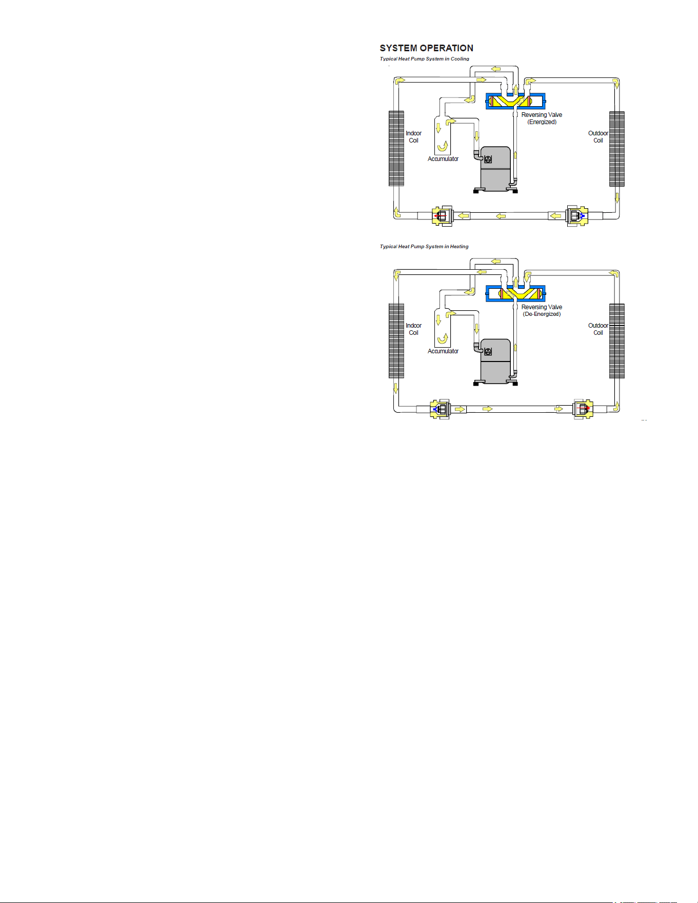
10
condenses to liquid. It then goes through the expansion
device to the outdoor coil (condenser on the cooling cycle)
where the liquid is evaporated, and the vapor goes to the
compressor.
When the solenoid valve coil is operated either from
heating to cooling or vice versa, the piston in the reversing
valve to the low pressure (high pressure) reverse positions
in the reversing valve.
Figure 7 shows a schematic of a heat pump on the cooling
cycle and the heating cycle. In addition to a reversing
valve, a heat pump is equipped with an expansion device
and check valve for the indoor coil, and similar equipment
for the outdoor coil. It is also provided with a defrost control
system.
The expansion devices are owrator distributors and
perform the same function on the heating cycle as on the
cooling cycle. The owrator distributors also act as check
valves to allow for the reverse of refrigerant ow.
When the heat pump is on the heating cycle, the outdoor
coil is functioning as an evaporator. The temperature
of the refrigerant in the outdoor coil must be below the
temperature of the outdoor air in order to extract heat from
the air. Thus, the greater the dierence in the outdoor
temperature and the outdoor coil temperature, the greater
the heating capacity of the heat pump. This phenomenon
is a characteristic of a heat pump. It is a good practice to
provide supplementary heat for all heat pump installations
in areas where the temperature drops below 45°F. It is also
a good practice to provide sucient supplementary heat
to handle the entire heating requirement should there be a
component failure of the heat pump, such as a compressor,
or refrigerant leak, etc.
Since the temperature of the liquid refrigerant in the
outdoor coil on the heating cycle is generally below
freezing point, frost forms on the surfaces of the outdoor
coil under certain weather conditions of temperature and
relative humidity. Therefore, it is necessary to reverse the
ow of the refrigerant to provide hot gas in the outdoor coil
to melt the frost accumulation. This is accomplished by
reversing the heat pump to the cooling cycle. At the same
time, the outdoor fan stops to hasten the temperature
rise of the outdoor coil and lessen the time required for
defrosting. The indoor blower continues to run and the
supplementary heaters are energized.
Heat Pump Refrigerant Circuit
Figure 7
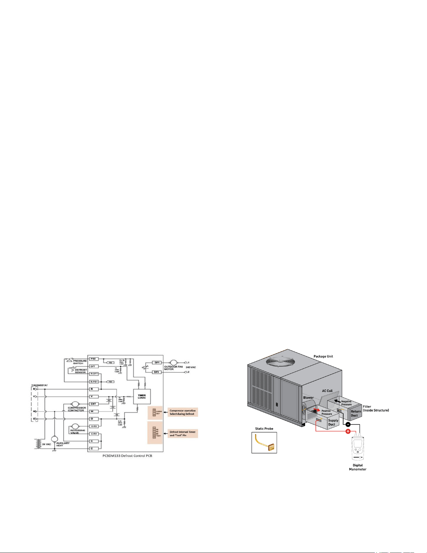
DEFROST CONTROL
During operation the power to the circuit board is controlled
by a temperature sensor, which is clamped to a feeder
tube entering the outdoor coil. Defrost timing periods of 30,
60 and 90 minutes may be selected by setting the circuit
board jumper to 30, 60 and 90 respectively. Accumulation
of time for the timing period selected starts when the
sensor closes (approximately 30 ± 5°F), and when the wall
thermostat calls for heat. At the end of the timing period,
the unit’s defrost cycle will be initiated provided the sensor
remains closed. When the sensor opens (approximately
60°F), the defrost cycle is terminated and the timing period
is reset. If the defrost cycle is not terminated due to the
sensor temperature, a twelve minute override interrupts the
unit’s defrost period.
SUGGESTED FIELD TESTING
/TROUBLESHOOTING
Testing Defrost Control
NOTE: PCBDM133 defrost controls have a three (3)
minute compressor off cycle delay.
11
NOTE: The PCBDM133 defrost controls are shipped
from the factory with the compressor delay option
selected. This will de-energize the compressor
contactor for 30 seconds on defrost initiation and
defrost termination. If the jumper is set to Normal,
the compressor will continue to run during defrost
initiation and defrost termination. The control will
also ignore the low-pressure switch connected to
R-PS1 and PS2 for 5 minutes upon defrost initiation
and 5 minutes after defrost termination.
To check the defrost control for proper sequencing,
proceed as follows: With power ON; unit not running.
1. Jumper defrost thermostat by placing a jumper wire
across the terminals “DFT” and “R”/” R-DFT” at
defrost control board.
2. Remove jumper from timer pins and jump across test
pins on defrost control board.
NOTE: Do not use screwdriver or eld supplied
jumper to test the control.
3. Set thermostat to call for heating. System should go
into defrost within 21 seconds.
4. Immediately remove jumper from test pins.
5. Using VOM check for voltage across terminals “C &
O”. Meter should read 24 volts.
6. Using VOM check for voltage across fan terminals
DF1 and DF2 on the board. Should read line voltage
(208-230 VAC) indicating the relay is open in the
defrost mode.
7. Using VOM check for voltage across “W”/”W2” & “C”
terminals on the board. Should read 24 volts.
8. If not as above, replace control board.
9. Set thermostat to o position and disconnect power.
Remove jumper from defrost thermostat and replace
timer jumper to the desired defrost time.
NOTE: Remove jumper across defrost thermostat
before returning system to service.
PCBDM133 Defrost Control
Figure 8
Testing Defrost Thermostat
1. Install a thermocouple type temperature test lead on
the tube adjacent to the defrost control. Insulate the
lead point of contact.
2. Check the temperature at which the control closes its
contacts by lowering the temperature of the control. It
should close at approximately 30°F.
3. Check the temperature at which the control opens its
contacts by raising the temperature of the control. It
should open at approximately 60°F.
4. If not as above, replace control.
AIR FLOW MEASUREMENT AND
ADJUSTMENT
After reviewing section on DUCTING, proceed with airow
measurements and adjustments. Unit’s blower curves
(in Specication Sheets) are based on external static
pressure (ESP, in. of W.C.). The duct openings on the unit
are considered internal static pressure, so as long as ESP
is maintained, the unit will deliver the proper air up to the
maximum static pressure listed for the CFM required by the
application (i.e. home, building, etc.).
In general 400 CFM per ton of cooling capacity is a rule
of thumb. Some applications depending on the sensible
and latent capacity requirements may need only 350
CFM or up to 425 CFM per ton. Check condition space
load requirements (from load calculations) and equipment
expanded ratings data to match CFM and capacity.
After unit is set and ducted, verify ESP with a 1” inclined
manometer with pitot tubes or a Magnahelic gauge
and conrm CFM to blower curves in the specication
sheets. All units have multiple speed blower motors. If
factory selected speed is not utilized, the speed tap can
be changed. Never run CFM below 350 CFM per ton,
evaporator freezing or poor unit performance is possible.
Total External Static Pressure
1. Using a digital manometer measure the static
pressure of the return duct at the inlet of the unit
(Negative Pressure).
Mode
.
Total External Static
Figure 9
2. Measure the static pressure of the supply duct
(Positive Pressure).
3. Add the two readings together.
12
NOTE: Both readings may be taken simultaneously
and read directly on the manometer if so desired.
4. Consult proper table for quantity of air.
If the external static pressure exceeds the minimum or
maximum allowable statics, check for closed dampers, dirty
lter, undersized or poorly laid out ductwork.
ADJUSTING SPEED TAP FOR INDOOR
BLOWER MOTOR
*PCH3[24-48]/*PHH3[24-60]41 Models
*PCH3[24-48]/*PHH3[24-60]41 models are equipped
with a multi-speed EEM motor.
EEM Motor
The blower motor speed for the EEM motor is controlled by
three 24V low voltage leads: green, yellow, and white. The
green lead sets the speed for fan-only mode. The yellow
lead sets the speed for cooling and heat pump heating
mode (if applicable).
EEM Motor Speed Adjustment
The white lead sets the speed for electric heat mode
(emergency heat and second stage heat, if applicable).
The leads are factory connected as follows: Green to
T1,Yellow to T2, and White to T3. T1 is the low speed
setting and is dedicated to fan-only mode. T2 is medium
speed cooling and T3 is medium speed heating. T4 is high
speed cooling and T5 is high speed heating. To adjust the
blower speed, move the yellow and/or white wires to T4
and T5.
NOTE: If more than one lead is energized at the
same time, the motor will use the higher speed
setting.
NOTE: *P*H units are rated for a maximum E.S.P. of
0.8 except when using a 20kw electric heater. (The
maximum static for 20 kW electric heat is 0.5 E.S.P.)
When these units are installed in the 0.5 - 0.8
E.S.P. range, the white lead (electric heat) must be
moved to T5 for proper operation of the electric
heaters.
APCH36041 Models
APCH36041models are equipped with a variable speed
ECM motor with a electronic control board.
ECM Motor
The ECM motor provides many features not available on
the traditional PSC motor. These features include:
• Improved Eciency
• Constant CFM
• Soft Start and Stop
• Improved Humidity Control
ECM Motor Speed Adjustment
Each ECM blower motor has been preprogrammed for
operation at 4 distinct air ow levels when operating in
Cooling/Heat Pump mode or Electric Heat mode. These 4
distinct levels may also be adjusted slightly lower or higher
if desired. The adjustment between levels and the trim
adjustments are made by changing the dip switch(s) either
to an “OFF” or “ON” position. See Blower Performance
Data tables in rear of manual.
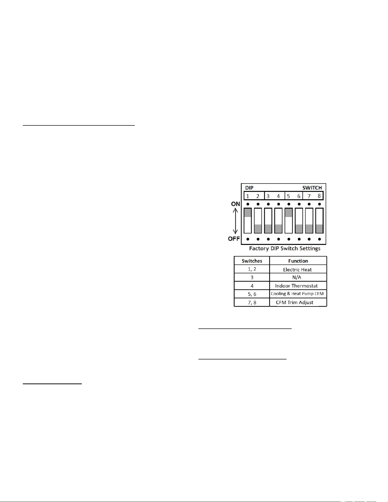
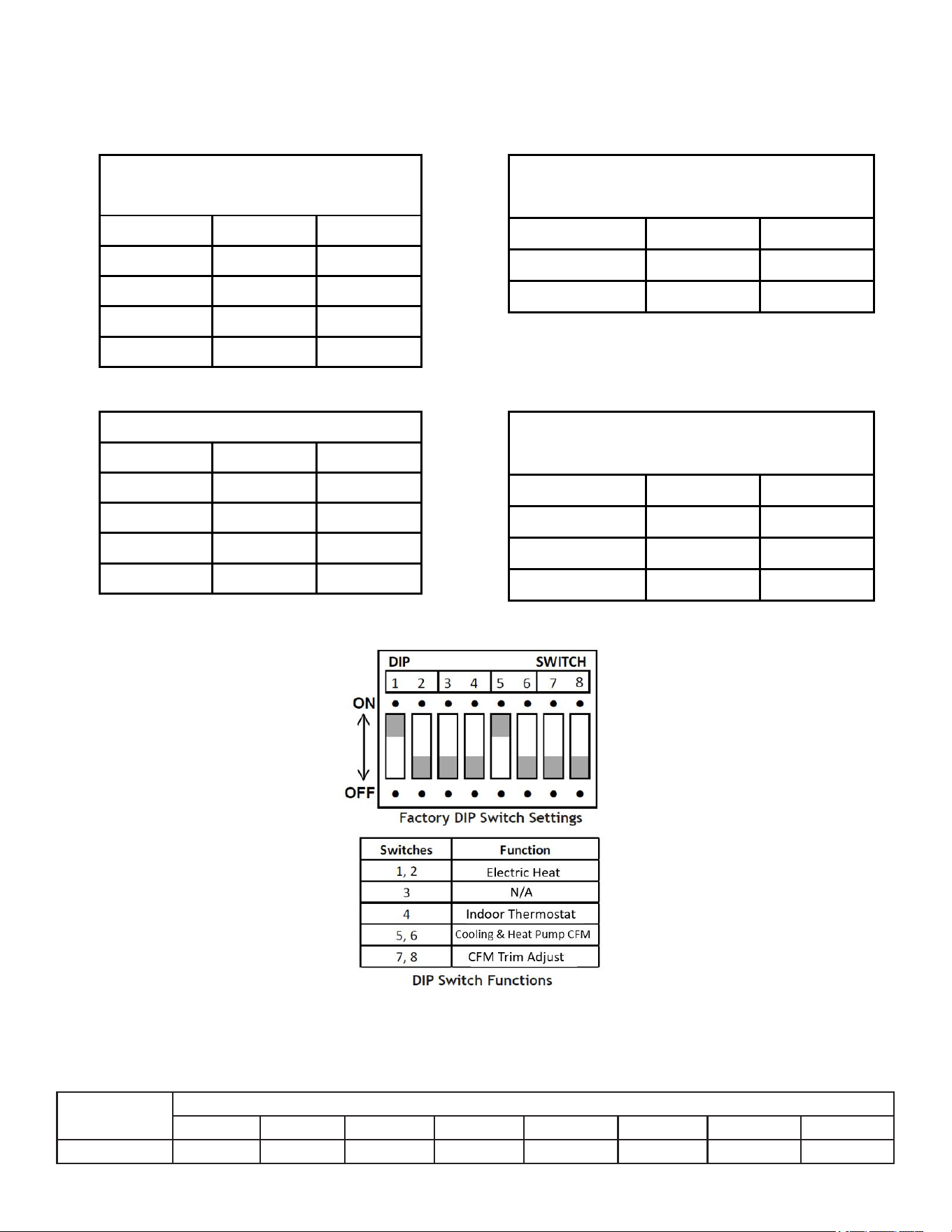
Dip Switch Functions
The ECM motor has an electronic control that contains
eight (8) 2-position dip switches. The function of these dip
switches is shown in Table 5. For APCH36041 models, dip
switch 4 must be set to ON. Dip switch 4 must be set to
OFF for the two-stage compressor model APCH36041. Dip
switch 4 ON energizes Y1 signal to the ECM motor anytime
Y/Y2 is energized. The indoor motor will not operate
properly if switch is not set correctly for the model. See
“Blower Performance” Section for DIP Switch settings.
APHH5 DIP Switch Functions
CFM Delivery and Adjustments
See pages 14-15 for CFM Output, Adjustments and DIP
switch settings.
Thermostat “Fan Only” Mode
Alternate Fan Only Speed
The APCH36041 models are equipped with ECM variable
speed motors. Two FAN ONLY speeds are possible with
these motors. To utilize the LOW HEAT blower speed
for FAN ONLY operation, connect the wire from the
thermostat’s G terminal to the PCBEM102 VSTB control
board’s G terminal.
To utilize the alternate FAN ONLY speed, connect the wire
from the thermostat’s G terminal to the unstripped green
wire in the control box. This alternate FAN ONLY blower
speed is approximately 75% of the HIGH COOL speed.
13
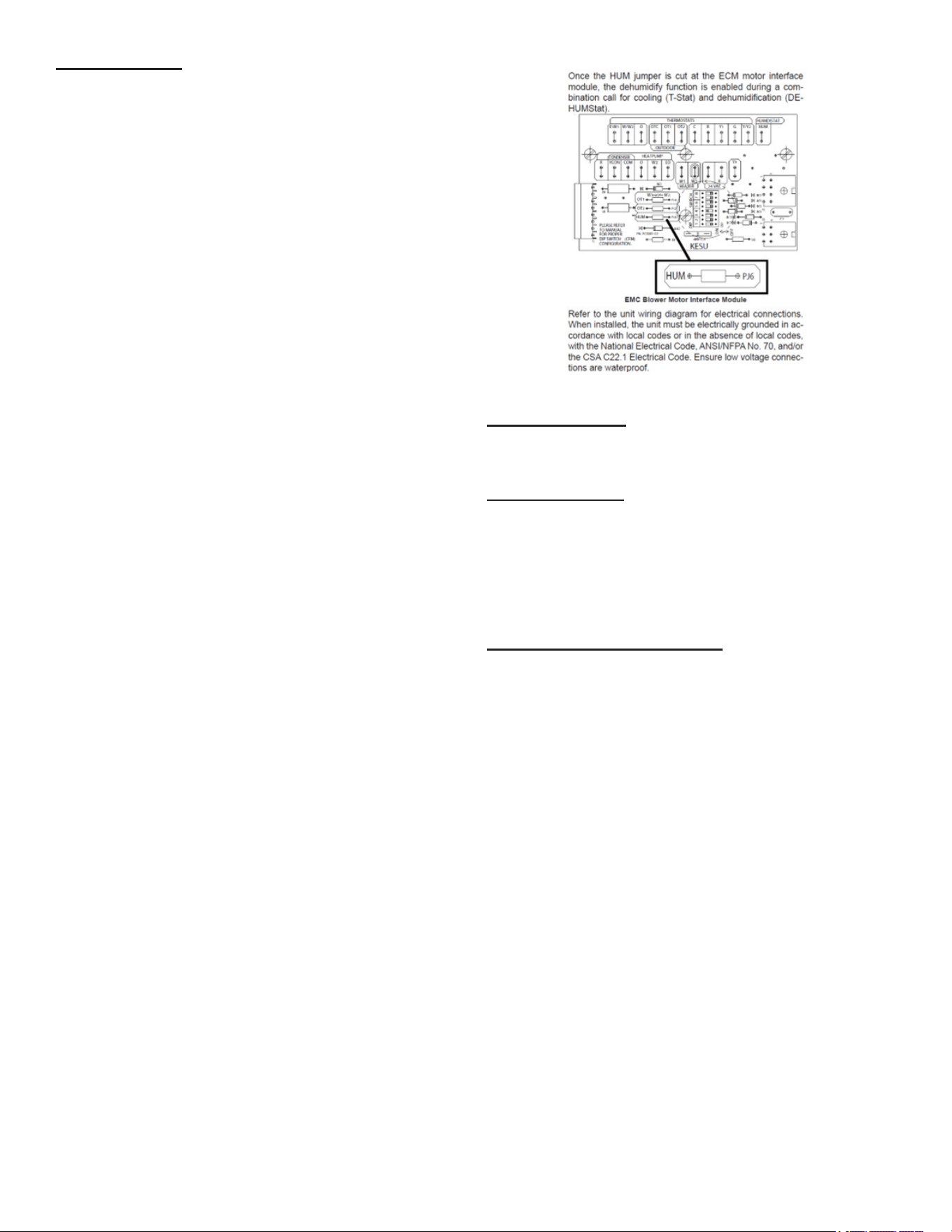
Humidity Control
APCH36041 Models are equipped with humidity control
feature. When using a Humidistat (normally closed), cut
jumper PJ6 on the PCBEM102 VSTB control board. The
Humidistat will only aect both low stage and high stage
cooling air ow by adjusting the Airow to 85% (See below
for details).
24 Volt Dehumidistat Wiring
The optional usage of a dehumidistat allows the unit’s
circulator blower to operate at a slightly lower speed
(approximately 80% of desired cooling speed) during a
combined thermostat call for cooling and dehumidistat
call for dehumidication. This can be done through an
independent dehumidistat. This lower blower speed
enhances dehumidication of the conditioned air as
it passes through the air conditioning coil. For proper
function, a dehumidistat applied to this package unit must
operate on 24 VAC and utilize a switch which opens on
humidity rise. Refer to the unit wiring diagram for additional
wiring details.
To install/connect a dehumidistat:
1. Turn OFF power to unit.
2. To enable the dehumidify function, locate the
PCBEM102 VSTB in the unit’s control box
section. Locate the jumper label “HUM” “PJ6”
on the interface module. Cut the jumper to enable
dehumidication
3. Secure the dehumidistat control wire (typically the
white lead) to the gray, unstripped wire in the unit’s
control box.
4. Secure the dehumidistat low voltage power wire
(typically the black lead) to the thermostat “R” (Red)
wire in control box
5. Secure the dehumidistat ground wire (typically the
green lead) to the ground screw to the unit’s sheet
metal control box.
NOTE: Ground wire may not be present on all
dehumidistats.
6. Turn ON power to unit. Once the HUM jumper is cut
at the ECM motor interface module, the dehumidify
function is enabled during a combination call for
cooling (T-Stat) and dehumidication (DehumStat).
(NOTE: Refer to specic Dehumidication Stat used
for wiring details.)
Figure 10
Two-Stage Heating
When using staged electric heat, cut jumper PJ4 on the
PCBEM102 VSTB control board.
Thermostat Wiring
Use thermostat wiring diagrams provided with the
thermostat when making these connections.
Refrigerant Charge Check
NOTE: For optimal performance, follow charging
instructions below.
Units with Fixed Orice Devices
After completing airow measurements and adjustments
the unit’s refrigerant charge must be checked. All package
units with xed orice devices are charged using the
superheat method at the compressor suction line. After
superheat is adjusted it is recommended to check unit
subcooling at the condenser coil liquid line out. For charge
adjustments, see superheat and subcooling charts shown
for each model.
Superheat can be determined as follows:
1. Read suction pressure. Determine Saturated Suction
Temperature from tables or pressure gauge saturated
temperature scale (R-410A).
2. Read suction line temperature.
3. Use the following formula:
SUPERHEAT = SUCTION LINE TEMP - SAT. SUCTION
TEMP.
14
Superheat Adjustment
NOTE: Superheat adjustments should not be made
until in door ambient conditions have stabilized.
This could take up to 24 hours depending on
indoor temperature and humidity. Before checking
superheat run the unit in cooling for 10-15 minutes
or until refrigerant pressues stabilize. Use the
fol lowing guidelines and methods to check unit
operation and ensure that the refrigerant charge
is within limits.
For TXV systems, to adjust superheat, unscrew the cover
from the expansion valve, locate the adjustment screw, and
turn it clockwise (in) to increase superheat or counterclock-
wise (out) to decrease superheat. It is recommended to
make small adjustments at a time, 1/8-1/4 turn increments.
Replace adjustment cap. Wait a minimum of 10 minutes.
Expansion Valve (TXV) System:
Two Speed Application (*PCH36041)
Run the unit on low stage cooling for 10 minutes until
refrigerant pressures stabilize. Follow the guideline and
methods below to check unit operation and ensure that the
refrigerant charge is within limits. Charge the unit on low
stage.
1. Purge gauge lines. Connect service gauge manifold
to access ttings. Run system at least 10 minutes to
allow pressure to stabilize.
2. Temporarily install thermometer on liquid (small) line
near liquid line access tting with adequate contact
and insulate for best possible reading.
3. Check subcooling and superheat. Two stage systems
running on low stage with TXV application should
have a subcooling and superheat within the range
listed on the chart.
a. If subcooling and superheat are low, adjust TXV
superheat, then check subcooling.
NOTE: To adjust superheat, turn the valve stem
clockwise to increase and counter clockwise to
decrease.
b. If subcooling is low and superheat is high, add
charge to raise subcooling then check superheat.
c. If subcooling and superheat are high, adjust TXV
valve superheat, then check subcooling.
d. If subcooling is high and superheat is low, adjust
TXV valve superheat and remove charge to lower
the subcooling.
NOTE: Do NOT adjust the charge based
on suction pressure unless there is a gross
undercharge.
4. Disconnect manifold set, installation is complete.
Checking Subcooling
NOTE: Units with a TXV should be charged to
Subcool ing only.
SUBCOOLING FORMULA = SATURATED LIQUID LINE
TEMPERATURE - LIQUID LINE TEMPERATURE
EXAMPLE:
a. Liquid Line Pressure = 417 PSI
b. Corresponding Temp. = 120°F
c. Thermometer on Liquid line = 109°F.
To obtain the amount of subcooling, subtract 109°F
from 120°F. The dierence is 11° subcooling. See
the specication sheet or technical information
manual for the design subcooling range for your
unit.
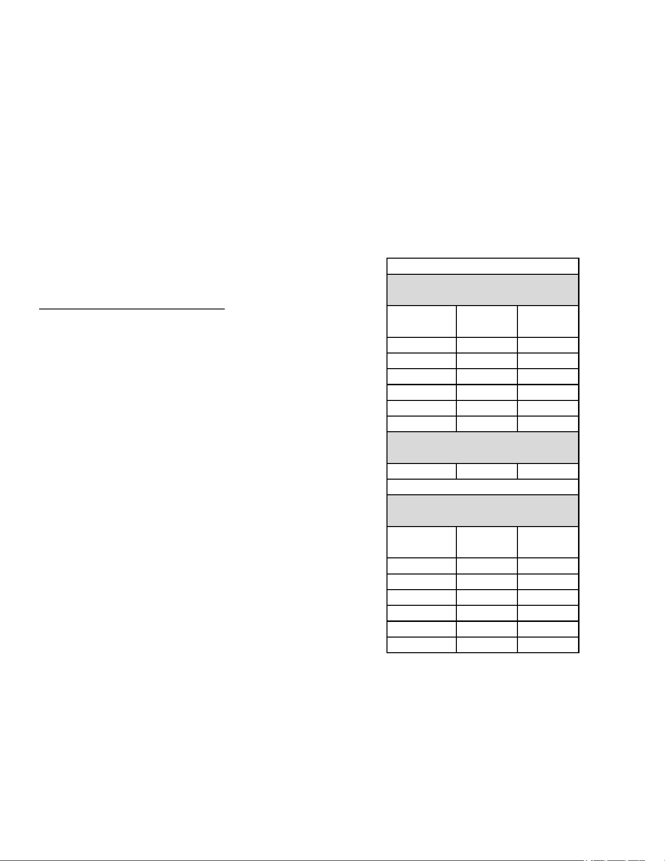
Model
Superheat
± 2°F
Subcooling
± 2°F
GPCH32441 17 -
APCH32441 15 -
*PCH33041 17 -
*PCH33641 9 -
*PCH34241 16 -
*PCH34841 8 -
*PCH36041 6 7
Model
Superheat
± 2°F
Subcooling
± 2°F
*PHH32441 4 -
*PHH33041 3 -
*PHH33641 4 -
*PHH34241 3 -
*PHH34841 14 -
*PHH36041 3 -
*PCH3
Design superheat @ 95°F outdoor
ambient temperature
Design superheat @ 82°F outdoor
ambient temperature
*PHH3
Design superheat @ 95°F outdoor
ambient temperature
15
SUBCOOLING FORMULA = SAT. LIQUID TEMP.
- LIQUID LINE TEMP.
SUCTION
PRESSURE
SATURATED
SUCTION
TEMPERATURE
ºF
LIQUID
PRESSURE
SATURATED
LIQUID
TEMPERATURE
ºF
PSIG
R-410A
PSIG
R-410A
50
1
200
70
52
3
210
73
54
4
220 76
56 6 225 78
58 7 235 80
60 8 245 83
62 10 255 85
64 11 265 88
66 13 275 90
68 14 285 92
70 15 295 95
72 16 305 97
74 17 325 101
76 19 355 108
78 20 375 112
80 21 405 118
85 24 415 119
90 26 425 121
95 29 435 123
100 31 445 125
110 36 475 130
120 41 500 134
130 45 525 138
140 49 550 142
150 53 575 145
160 56 600 149
170 60 625 152
SATURATED
SUCTION PRESSURE
TEMPERATURE CHART
SATURATED
LIQUID PRESSURE
TEMPERATURE CHART
Table 6
Suction Pressure Liquid Pressure
Temperature (R-410A) Temperature (R-410A)
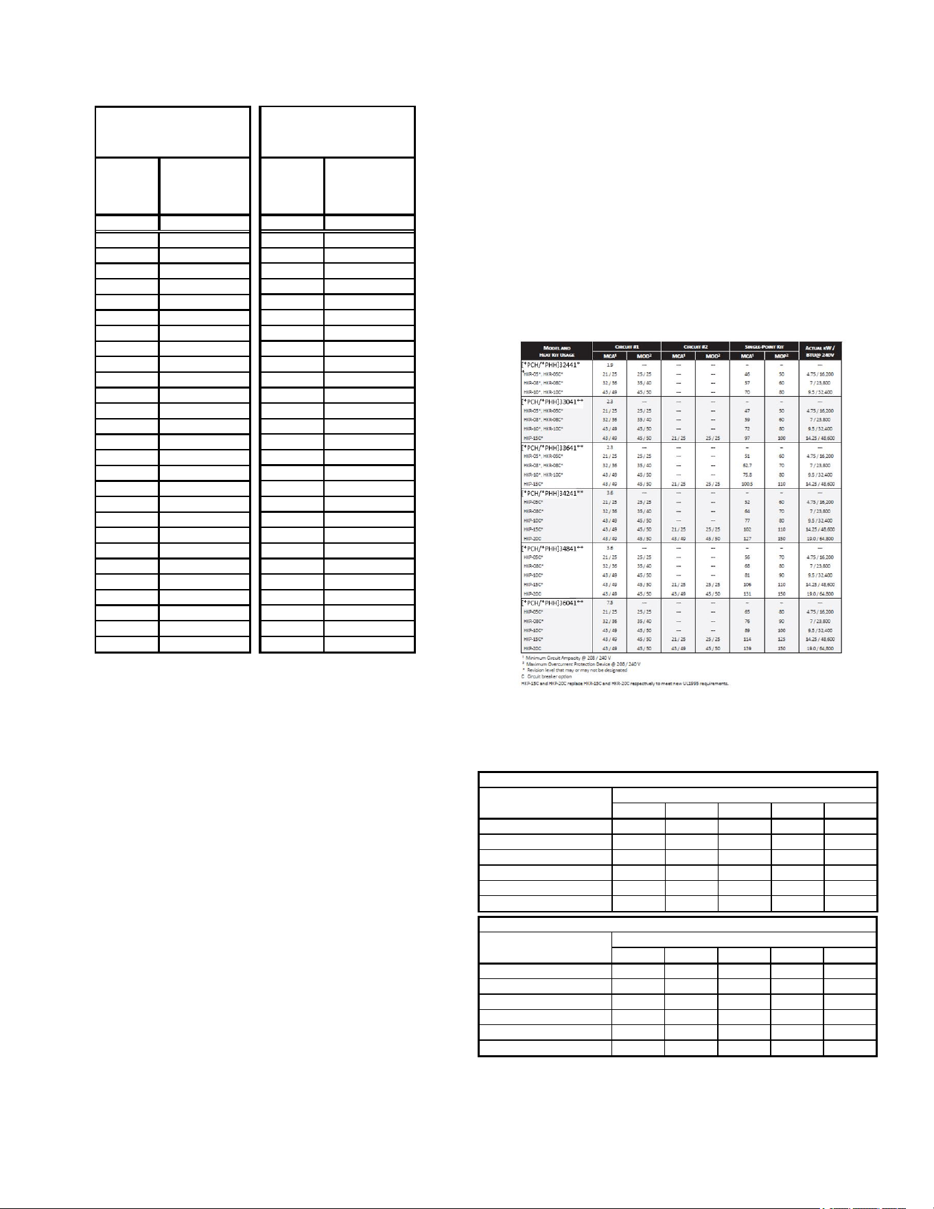
ELECTRIC HEAT INSTALLATION
Heater Kit
NOTE: A separate power supply is required for the
HKR/HKP heater kits.
Refer to the Heat Kit Electrical Data (Blower Only, Heat
Mode) specication table below for heater kit match up
and heater kit electrical data information. See specic kit
installation manual for installation instructions.
This series of electric cooling and heat pump package
equipment is designed to accept a eld installed electric
heat kit. The unit is equipped to easily install the HKR/HKP
Series Electric Heat Kit. Full Installation Instructions are
included in this kit. Please use this document for guidance
in eld equipping the package unit with electric heat.
Choose the heat kit that ts the application for the specic
installation. Permanently mark the unit’s nameplate
with the model being installed. High and low voltage
connections are detailed in the heat kit instructions.
Indoor Blower motor speed tap selection may need to be
modied to accommodate normal continuous operation to
prevent a nuisance trip. See following table.
*PCH3 / *PHH3
Indoor Blower motor speed tap selection may need to be
modied to accommodate normal continuous operation to
prevent a nuisance trip. See following table.
5 8 10 15 20
[*PCH/*PHH]32441** T3 T3 T3 NA NA
[*PCH/*PHH]33041** T3 T3 T3 T5 NA
[*PCH/*PHH]33641** T3 T3 T3 T5 NA
[*PCH/*PHH]34241** T3 T3 T3 T5 T5
[*PCH/*PHH]34841** T3 T3 T3 T5 T3
[GPCH/*PHH]36041** T3 T3 T3 T5 T3
*PCH3[24-48]/*PHH3[24-60]41 Models (0 - 0.5 E.S.P.)
Electric Heat KW
Unit Model Number
5 8 10 15 20
[*PCH/*PHH]32441** T5 T5 T5 T5 NA
[*PCH/*PHH]33041** T5 T5 T5 T5 NA
[*PCH/*PHH]33641** T5 T5 T5 T5 NA
[*PCH/*PHH]34241** T5 T5 T5 T5 NA
[*PCH/*PHH]34841** T5 T5 T5 T5 NA
[GPCH/*PHH]36041** T5 T5 T5 T5 NA
*PCH3[24-48]/*PHH3[24-60]41 Models (0.5 -0.8 E.S.P.)
Unit Model Number
Electric Heat KW
T1 - Fan Only, T2 - Normal Speed Cooling
T3 - Normal Speed Heating
T4 - High Speed Cooling, T5 - High Speed Cooling
16
APCH36041 Models
See “Blower Performance” section for Electric Heat DIP
Switch settings.
MAINTENANCE
WARNING
HIGH VOLTAGE!
Disconnect all power before servicing or in-
stalling this unit. Multiple power sources may
be present. Failure to do so may cause proper-
ty damage, personal injury or death.
The Self Contained Package Air Conditioner and Heat
Pump should operate for many years without excessive
service calls if the unit is installed properly. However it
is recommended that the homeowner inspect the unit
before a seasonal start up. The coils should be free of
debris so adequate airow is achieved. The return and
supply registers should be free of any obstructions. The
lters should be cleaned or replaced. These few steps
will help to keep the product up time to a maximum.
The Troubleshooting Chart (on page 16) should help in
identifying problems if the unit does not operate properly.
SERVICE
THE FOLLOWING INFORMATION IS FOR USE BY
QUALIFIED SERVICE AGENCY ONLY: OTHERS
SHOULD NOT ATTEMPT TO SERVICE THIS
EQUIPMENT.
Common Causes of Unsatisfactory Operation of Heat
Pump on the Heating Cycle.
Inadequate Air Volume Through Indoor Coil
When a heat pump is in the heating cycle, the indoor coil
is functioning as a condenser. The return air lter must
always be clean, and sucient air volume must pass
through the indoor coil to prevent excessive discharge
pressure, and high pressure cut out.
Outside Air Into Return Duct
Do not introduce cold outside air into the return duct of a
heat pump installation. Do not allow air entering the indoor
coil to drop below 65°F. Air below this temperature will
cause low discharge pressure, thus low suction pressure,
and excessive defrost cycling resulting in low heating
output. It may also cause false defrosting.
Undercharge
An undercharged heat pump on the heating cycle will
cause low discharge pressure resulting in low suction
pressure and frost accumulation on the outdoor coil.
Poor “Terminating” Sensor Contact
The unit’s defrost terminating sensor must make good
thermal contact with the outdoor coil tubing. Poor contact
may not terminate the unit’s defrost cycle quickly enough
to prevent the unit from cutting out on high discharge
pressure.
Malfunctioning Reversing Valve
This may be due to:
1. Solenoid not energized - In order to determine if the
solenoid is energized, touch the nut that holds the
solenoid cover in place with a screwdriver. If the nut
magnetically holds the screwdriver, the solenoid is
energized and the unit is in the cooling cycle.
2. No voltage at unit’s solenoid - Check unit voltage. If
no voltage, check wiring circuit.
3. Valve will not shift:
a. Undercharged - check for leaks;
b. Valve Body Damaged - Replace valve;
c. Unit Properly Charged - If it is on the heating
cycle, raise the discharge pressure by restricting
airow through the indoor coil. If the valve
does not shift, tap it lightly on both ends with
a screwdriver handle. Do Not Tap The Valve
Body. If the unit is on the cooling cycle, raise the
discharge pressure by restricting airow through
the outdoor coil. If the valve does not shift after
the above attempts, cut the unit o and wait until
the discharge and suction pressure equalize, and
repeat above steps. If the valve does not shift,
replace it.
17
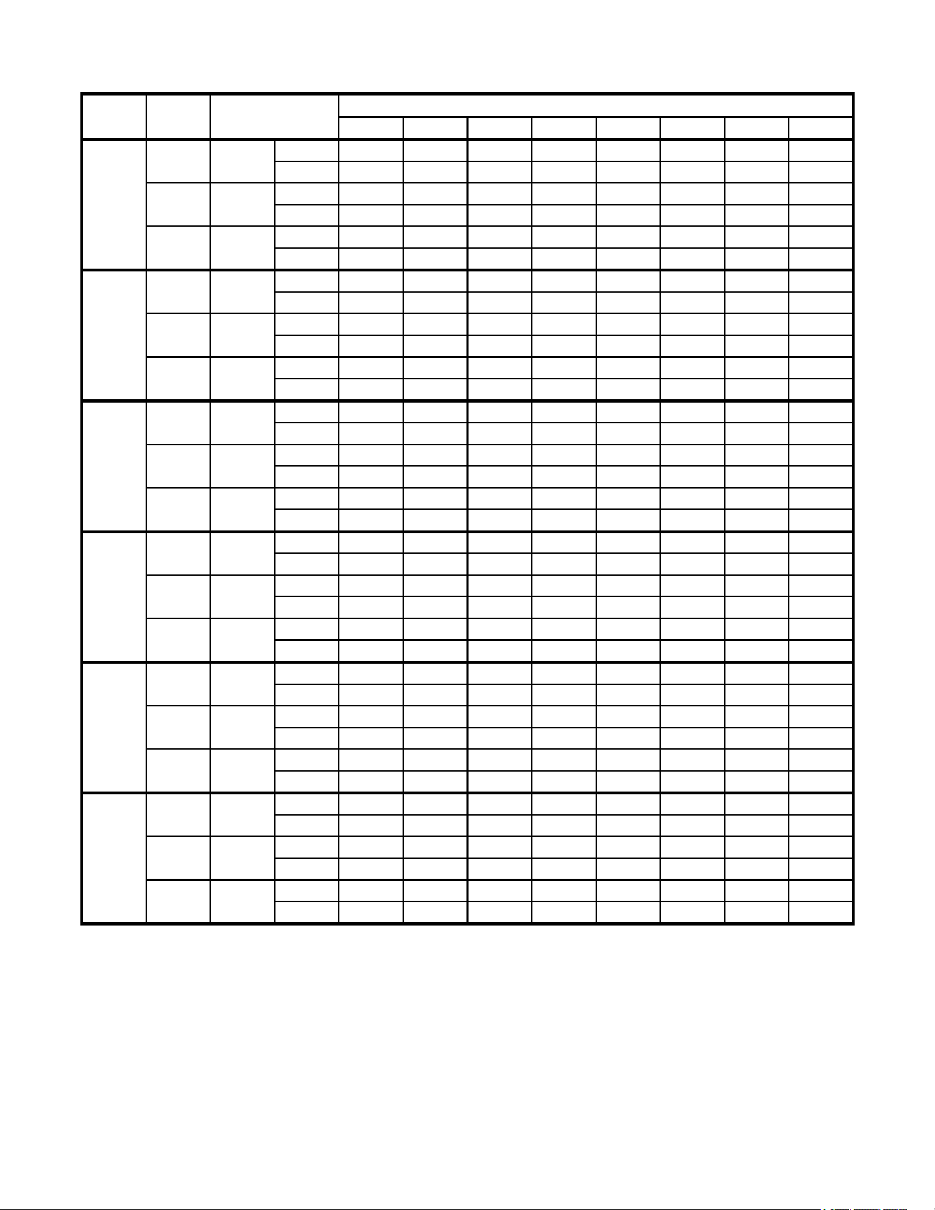
0.1 0.2 0.3 0.4 0.5 0.6 0.7 0.8
CFM 922 873 823 774 724 675 626 576
Watts 74 85 96 107 118 129 140 151
CFM 1172 1121 1068 1012 953 892 832 762
Watts 135 145 155 164 175 186 184 203
CFM 1231 1179 1127 1074 1022 969 917 865
Watts 168 180 193 205 2108 230 243 255
CFM 864 808 757 695 636 567 494 437
Watts 72 82 91 103 107 115 123 131
CFM 1323 1270 1220 1171 1119 1060 997 945
Watts 179 190 199 209 219 230 240 248
CFM 1404 1362 1321 1271 1238 1191 1150 1105
Watts 235 246 257 272 284 289 300 309
CFM 1161 1113 1076 1034 994 949 889 837
Watts 139 150 163 172 184 194 207 218
CFM 1379 1343 1305 1265 1226 1190 1148 1108
Watts 216 229 241 254 264 276 285 296
CFM 1542 1502 1462 1427 1392 1352 1316 1280
Watts 291 301 314 327 339 349 359 371
CFM 1271 1214 1167 1127 1095 1052 1013 971
Watts 168 177 188 200 214 224 235 249
CFM 1491 1451 1406 1369 1335 1295 1262 1226
Watts 245 258 268 281 294 305 318 330
CFM 1736 1679 1638 1598 1558 1520 1484 1441
Watts 356 372 382 395 408 422 433 442
CFM 1337 1297 1218 1155 1118 1088 1022 989
Watts 179 190 203 210 225 243 249 268
CFM 1758 1715 1674 1637 1596 1557 1518 1474
Watts 394 406 418 430 443 455 466 474
CFM 2002 1935 1885 1827 1767 1732 1669 1618
Watts 498 521 516 534 551 567 571 574
CFM 1418 1357 1315 1274 1239 1193 1148 1102
Watts 212 219 227 236 243 252 266 275
CFM 1862 1812 1763 1719 1685 1649 1615 1583
Watts 437 447 454 461 473 480 483 493
CFM 1933 1886 1838 1796 1759 1723 1693 1669
Watts 491 499 506 519 527 534 539 550
*PCH33041**
T1 230
T2 / T3 230
T4 / T5 230
*PCH33641**
T1 230
T2 / T3 230
T4 / T5 230
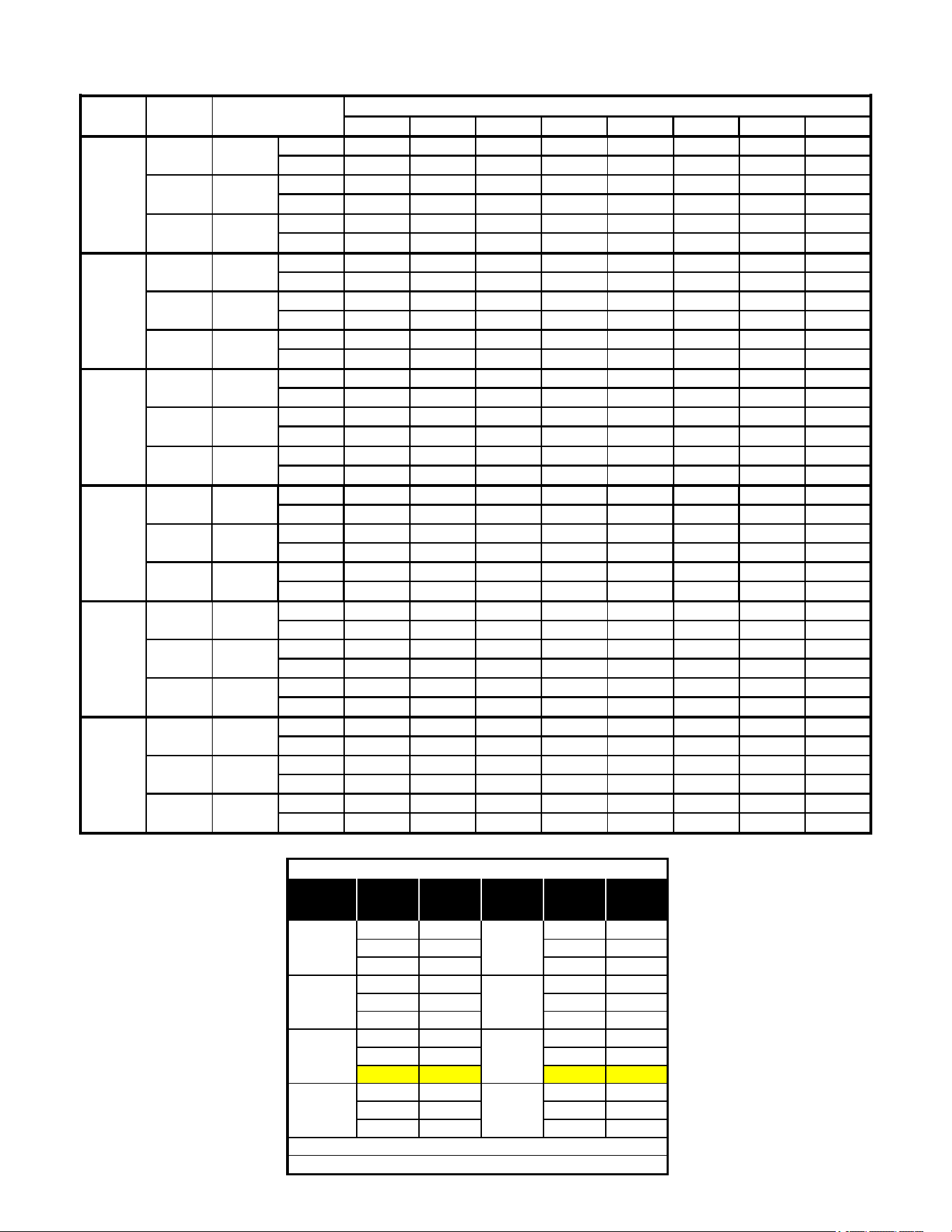
*PCH3[24-60]41 BLOWER PERFORMANCE
Model Speed Volts
NEW E.S.P. (In. of H
2
O)
*PCH32441**
T1 230
T2 / T3 230
T4 / T5 230
230
T2 / T3 230
T4 / T5 230
*PCH34241**
T1 230
T2 / T3 230
T4 / T5 230
GPCH36041**
T1 230
T2 / T3 230
T4 / T5 230
*PCH34841**
T1
APCH3[24-48]/GPCH3[24-60]41 BLOWER PERFORMANCE
Minus 1,506 Minus 1,506
Normal 1,699 Normal 1,699
Plus 1,872 Plus 1,872
Minus 1,420 Minus 1,420
Normal 1,596 Normal 1,596
Plus 1,764 Plus 1,764
Minus 1,323 Minus 1,323
Normal 1,491 Normal 1,491
Plus** 1,642 Plus** 1,642
Minus 1,217 Minus 1,217
Normal 1,385 Normal 1,385
Plus 1,537 Plus 1,537
APCH36041 Blower Performance
Cooling /
HP Speed
Adjust
Tap
CFM*
Electric
Heat
Adjust
Tap
CFM*
* - @ 0.1 - 0.8 ESP
** - Factory Default
D
C
B
A
D
C
B
A
18
Speed Tap Switch 1 Switch 2
A OFF OFF
B ON OFF
C OFF ON
D ON ON
Electric Heat
DIP Switch Settings
Thermostat Switch 3 Switch 4
Single-Stage N/A ON
Two-Stage N/A OFF
DIP Switch Settings for
Single & Two-Stage Thermostat
Speed Tap Switch 5 Switch 6
A OFF OFF
B ON OFF
C OFF ON
D ON ON
Cooling/HP DIP Switch Settings
CFM Switch 7 Switch 8
Plus 10% ON OFF
Normal OFF OFF
Minus 10% OFF ON
Speed Tap Adjustment
Through DIP Switches
DIP SWITCH FUNCTION SELECTION
Model
Default DIP Switch Setting
1 2 3 4 5 6 7 8
APCH36041 ON OFF OFF OFF ON OFF ON OFF
APCH360 DIP SWITCH SETTINGS
19
0.1 0.2 0.3 0.4 0.5 0.6 0.7 0.8
CFM 922 873 823 774 724 675 626 576
Watts 74 85 96 107 118 129 140 151
CFM 1172 1121 1068 1012 953 892 832 762
Watts 135 145 155 164 175 186 184 203
CFM 1231 1179 1127 1074 1022 969 917 865
Watts 168 180 193 205 2108 230 243 255
CFM 864 808 757 695 636 567 494 437
Watts 72 82 91 103 107 115 123 131
CFM 1323 1270 1220 1171 1119 1060 997 945
Watts 179 190 199 209 219 230 240 248
CFM 1404 1362 1321 1271 1238 1191 1150 1105
Watts 235 246 257 272 284 289 300 309
CFM 1161 1113 1076 1034 994 949 889 837
Watts 139 150 163 172 184 194 207 218
CFM 1379 1343 1305 1265 1226 1190 1148 1108
Watts 216 229 241 254 264 276 285 296
CFM 1542 1502 1462 1427 1392 1352 1316 1280
Watts 291 301 314 327 339 349 359 371
CFM 1271 1214 1167 1127 1095 1052 1013 971
Watts 168 177 188 200 214 224 235 249
CFM 1491 1451 1406 1369 1335 1295 1262 1226
Watts 245 258 268 281 294 305 318 330
CFM 1736 1679 1638 1598 1558 1520 1484 1441
Watts 356 372 382 395 408 422 433 442
CFM 1337 1297 1218 1155 1118 1088 1022 989
Watts 179 190 203 210 225 243 249 268
CFM 1758 1715 1674 1637 1596 1557 1518 1474
Watts 394 406 418 430 443 455 466 474
CFM 2002 1935 1885 1827 1767 1732 1669 1618
Watts 498 521 516 534 551 567 571 574
CFM 1418 1357 1315 1274 1239 1193 1148 1102
Watts 212 219 227 236 243 252 266 275
CFM 1862 1812 1763 1719 1685 1649 1615 1583
Watts 437 447 454 461 473 480 483 493
CFM 1933 1886 1838 1796 1759 1723 1693 1669
Watts 491 499 506 519 527 534 539 550
*PHH36041**
T1 230
T2 / T3 230
T4 / T5 230
*PHH34841**
T1 230
T2 / T3 230
T4 / T5 230
*PHH34241**
T1 230
T2 / T3 230
T4 / T5 230
*PHH33641**
T1 230
T2 / T3 230
T4 / T5 230
*PHH33041**
T1 230
T2 / T3 230
T4 / T5 230
*PHH32441**
T1 230
T2 / T3 230
T4 / T5 230
*PHH3[24-60]41 BLOWER PERFORMANCE
Model Speed Volts
NEW E.S.P. (In. of H
2
O)
*PHH3[24-60]41 BLOWER PERFORMANCE
NOTES:
1. Data shown is dry coil. Wet coil pressure drop is approx.
2. Data shown does not include filter pressure drop, approx. 0.08” H2O.
3. Reduce airflow by 2% for 208V operation.
20
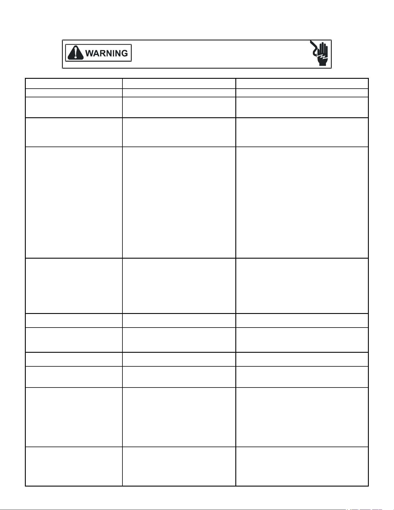
SYMPTOM
High head - low suction
a.
Restriction in liquid line or flowrator
a.
Remove or replace with proper size flowrator.
High head - high or normal suction
a.
Dirty condenser coil
a.
Clean coil
b.
Overcharged
b.
Correct System charge
c.
Condenser fan not running
c.
Repair or Replace
a.
Incorrect flowrator
a.
Replace with correct flowrator
b.
Defective compressor valves
b.
Replace compressor
c.
Flowrator not seating properly
c.
Check for debris under flowrator or deformed
flowrator. Remove debris or replace flowrator.
a.
Power off or loose electrical connection
a.
Check for unit voltage at contactor in unit
b.
Thermostat out of calibration set too high
b.
Reset
c.
Defective contactor
c.
Check for 24 volts at contactor coil replace if
contacts are open
d.
Blown fuses or tripped breaker
d.
Replace fuse or reset breaker Check wiring -
replace transformer
e.
Transformer defective
f.
High or low pressure control open
(Optional)
f.
Reset high pressure control or check unit charge
High pressure control opens at 610 psig
Low pressure control opens at 22 psig
g.
Compressor overload contacts open
g.
Replace compressor
NOTE: Wait at least 2 hours for overload to
reset
Condenser fan runs,
compressor doesn't
a.
Loose connection
a.
Check for unit voltage at compressor check &
tighten all connections
b.
Compressor stuck, grounded or open
winding
open internal overload
b.
Wait at least 2 hours for overload to reset If still
open, replace the compressor.
c.
Low voltage connection
c.
At compressor terminals, voltage must be within
10 % of nameplate volts when unit is operating
d.
Capacitor weak, open, or shorted
d.
Check capacitor. If defective, replace.
Low suction - cool compressor
a.
a.
Iced evaporator coil
a.
Defective overload protector
a.
Replace - check for correct voltage
b.
Unit cycling on low pressure control
b.
Check refrigerant charge and / or airflow
c.
High pressure switch cuts out
c.
Check airflow (Indoor & outdoor)
a.
a.
Increase speed of blower or reduce restriction
replace air filters
a.
Excessive load
a.
Recheck load calculation
b.
Defective compressor b.
Replace
c.
Reversing valve not seating properly.
c.
Replace
a.
Improperly sized unit
a.
Recalculate load
b.
Improper airflow
b.
Check - should be approximately 400 CFM per ton
c.
Incorrect refrigerant charge.
c.
Charge per procedure attached to unit service
panel
d.
Incorrect voltage
d.
At compressor terminals, voltage must be within
10% of nameplate volts when unit is
operating
Evaporator coil freezing or frosting
a.
Low airflow
a.
Check - should be approximately 400 CFM per
ton, dirty air filters, all duct outlets open
b.
Low refrigerant charge
b.
Properly charge unit
c.
Operating unit in cooling mode below 65°F
outdoor temperature
c.
Install or check low ambient control, should be
open below 65°F outdoor temperature
Low indoor airflow
Increase speed of blower or reduce restriction -
replace air filters
Insufficient cooling
High suction pressure
REMEDY
POSSIBLE CAUSE
Compressor short cycles
Registers sweat
Low airflow
Low head - high suction
Unit will not run
TROUBLESHOOTING CHART
HIGH VOLTAGE!
D
ISCONNECT
ALL
POWER
BEFORE
SERVICING
OR
INSTALLING
THIS
UNIT
.
M
ULTIPLE
POWER
SOURCES
MAY
BE
PRESENT
. F
AILURE
TO
DO
SO
MAY
CAUSE
PROPERTY
DAMAGE
,
PERSONAL
INJURY
OR
DEATH
.
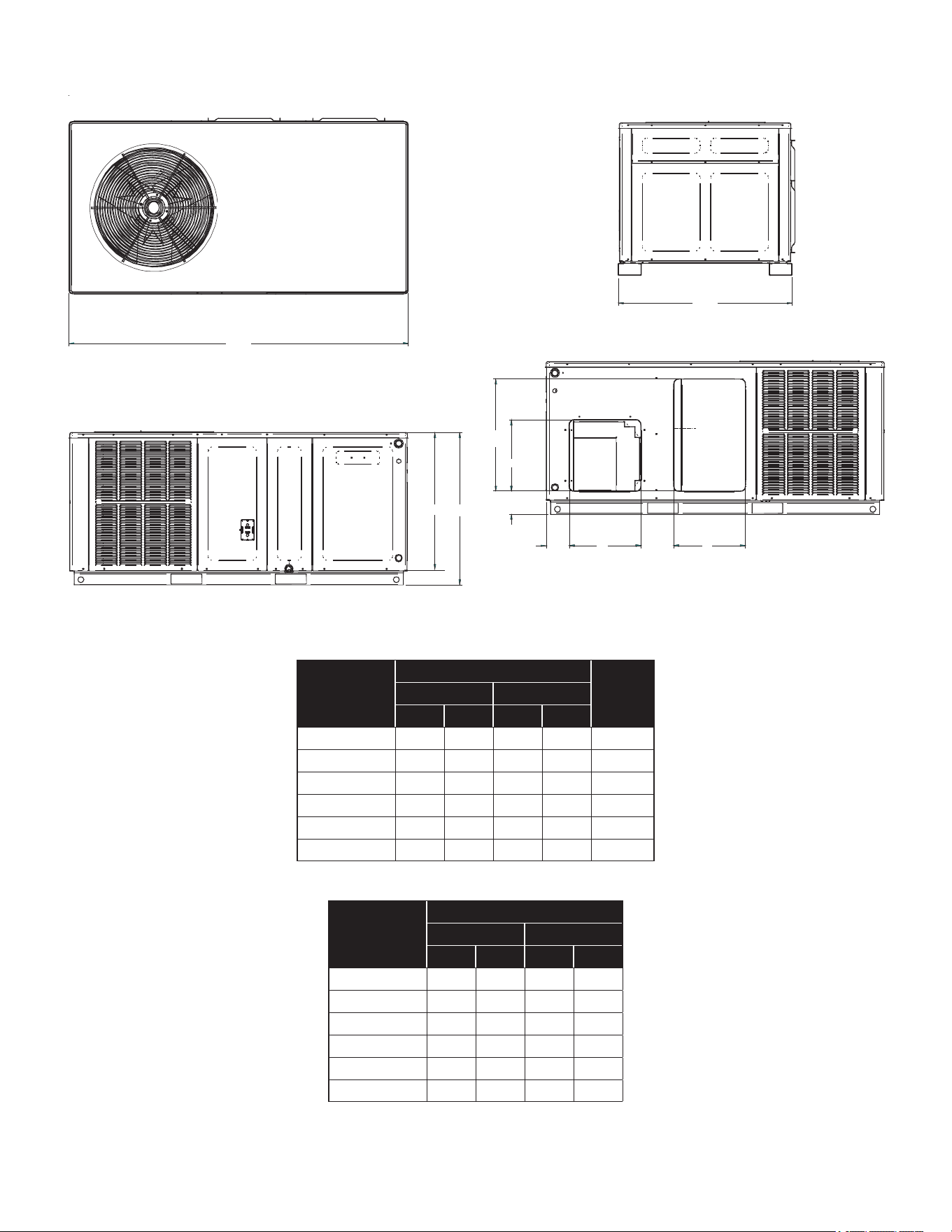
21
UNIT DIMENSIONS *PCH3
34”
66”
BA
4.5”
H
W
SUPPLY
6.5”
RETURN
4.5”
BACK VIEW
(DUCT OPENINGS)
H
W
Model
Unit Dimensions
Chassis
Size
Height
W D A B
*PCH32441** 66 34 27½ 30 Small
*PCH33041**
66 34
27½
30 Small
*PCH33641* 66 34
27½
30
Small
*PCH34241**
66 34 32½ 35 Medium
*PCH34841** 66 34 32½ 35 Medium
*PCH36041** 66 34 32½ 35
Medium
Model
Duct Openings
Supply Return
W H W H
*PCH32441** 14 14 14 22
*PCH33041** 14 14 14 22
*PCH33641** 14 14 14 22
*PCH34241** 14 14 14 22
*PCH34841** 14 14 14 24
*PCH36041** 14 14 14 24
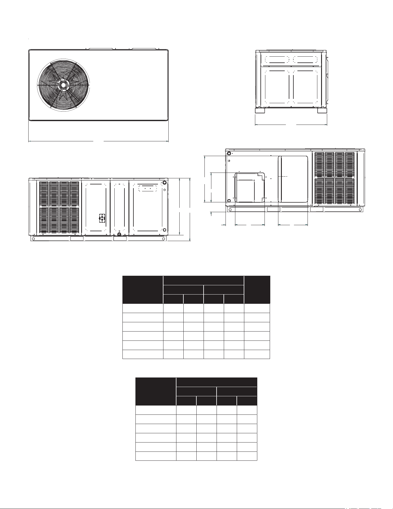
22
34”
66”
BA
4.5”
H
W
SUPPLY
6.5”
RETURN
4.5”
BACK VIEW
(DUCT OPENINGS)
H
W
UNIT DIMENSIONS *PHH3
Model
Unit Dimensions
Chassis
Size
Height
W D A B
*PHH32441** 66 34 27½ 30 Small
*PHH33041**
66 34
27½
30 Small
*PHH33641* 66 34
32½
35
Medium
*PHH34241**
66 34 32½ 35 Medium
*PHH34841** 66 34 32½ 35 Medium
*PHH36041** 66 34 36 38½
Large
Model
Duct Openings
Supply Return
W H W H
*PHH32441** 14 14 14 22
*PHH33041** 14 14 14 22
*PHH33641** 14 14 14 24
*PHH34241** 14 14 14 24
*PHH34841** 14 14 14 24
*PHH36041** 14 14 14 24
23
PACKAGE UNITS - H E AT P U M P A N D A C U N I T S
HOMEOWNER’S Routine Maintenance Recommendations
We strongly recommend a bi-annual maintenance checkup be performed by a qualied service agency before the heating and cooling seasons begin.
WARNING
HIGH VOLTAGE!
Disconnect all power before servicing or in-
stalling this unit. Multiple power sources may
be present. Failure to do so may cause proper-
ty damage, personal injury or death.
Replace or Clean Filter
IMPORTANT NOTE: Never operate unit without a
filter installed as dust and lint will build up on
internal parts resulting in loss of efficiency,
equipment damage and possible fire.
A return air filter is not supplied with this unit;
however, there must be a means of filtering the
return air. An indoor air filter must be used with
your comfort system. A properly maintained filter
will keep the indoor coil of your comfort system
clean. A dirty coil could cause poor operation
and/or severe equipment damage.
The installer of your unit can tell you where your lter(s)
are and how to clean or replace them.
Check your return lter(s) at least once every two months.
When they are dirty, replace or clean as required.
Disposable type lters should be replaced. Reusable type
lters may be cleaned.
NOTE: Reusable type filters should be washed
with warm water, dried completely and sprayed
with an adhesive according to the manufacturers
recommendations.
You may want to ask your dealer about high eciency
lters. High eciency lters are available in both electronic
and non-electronic types. These lters can do a better job
of catching small airborne particles.
Improper lter maintenance is the most common cause of
inadequate heating or cooling performance. Filters should
be cleaned (permanent) or replaced (disposable) every two
months or as required. When replacing a lter, it must be
replaced with a lter of the same type and size and always
make certain the air ow arrows on the lter point in the
proper direction.
Condenser and Evaporator Motors
The bearings on the air circulating blower motor and
condenser motor are permanently lubricated and require
no further lubrication.
Compressor
The compressor motor is hermetically sealed and does not
require additional oiling.
Aluminum Indoor Coil Cleaning
(Qualified Servicer Only)
This unit is equipped with an aluminum tube evaporator
coil. The safest way to clean the evaporator coil is to
simply ush the coil with water. This cleaning practice
remains as the recommended cleaning method for both
copper tube and aluminum tube residential cooling coils.
An alternate cleaning method is to use one of the products
listed in the technical publication TP-109 (shipped in the
literature bag with the unit) to clean the coils. The cleaners
listed are the only agents deemed safe and approved
for use to clean round tube aluminum coils. TP-109 is
available on the web site in Partner Link > Service Toolkit.
NOTE: Ensure coils are rinsed well after use of
any chemical cleaners.
Annual Inspection (Qualified Servicer Only)
Your package unit should be inspected by a qualied
installer, or service agency at least twice every year.
This check should be performed before the heating and
cooling seasons begin. This will ensure that the system is
performing properly and safely. Repair as necessary.
• Check physical support of the unit. Ensure it is sound
without any sagging, cracks, or gaps, around the base.
• Check for obvious signs of deterioration of the unit.
• Check both condenser and evaporator coil to make
sure each are clean.
• Return Air Connection. Check for physical soundness
and ensure that the connection is rmly sealed to the
package unit casing.
• Wiring. Check wires for damage. Check electrical
connections for tightness and/or corrosion.
• Filters. Check that lters are clean and in the proper
placement in the unit or duct system.
• Louvers. Inspect air inlet louvers inside the heat
exchanger compartments. Ensure the area is clean
and free of dirt and debris.
Before Calling Your Servicer
• Check the thermostat to conrm that it is properly set.
• Check the disconnect switch near the unit to conrm
that it is closed.
• Check the electrical panel for tripped circuit breakers
or failed fuses. Reset the circuit breakers or replace
fuses as necessary.
• Check for blockage of the indoor air inlets and outlets.
Conrm that they are open and have not been
blocked by objects (rugs, curtains or furniture).
• Check for obstructions on the unit. Conrm that it has
not been covered on the sides or the top. Remove
any obstruction that can be safely removed. If the unit
is covered with dirt or debris, call a qualied servicer
to clean it.
• Check the lter. If it is dirty, clean or replace it.
24
START-UP CHECKLIST
Residential Package - (Indoor Section)
ELECTRICAL
Line Voltage (Measure L1 and L2 Voltage) L1 - L2
Secondary Voltage (Measure Transformer Output Voltage) R - C
Blower Amps
Heat Strip 1 - Amps
Heat Strip 2 - Amps
BLOWER EXTERNAL STATIC PRESSURE
Return Air Static Pressure IN. W.C.
Supply Air Static Pressure IN. W.C.
Total External Static Pressure (Ignoring +/- from the reading above, add total here) IN. W.C.
TEMPERATURES
Return Air Temperature (Dry bulb / Wet bulb) DB °F WB °F
DB °F WB °F
Heating Supply Air Temperature DB °F
Temperature Rise DB °F
Delta T (Difference between Supply and Return Temperatures) DB °F
GAS PRESSURES
Gas Inlet Pressure IN. W.C.
Gas Manifold Pressure (Low Fire) IN. W.C.
Gas Manifold Pressure (High Fire) IN. W.C.
Gas Type (NG) = Natural Gas / (LP) = Liquid Propane
Residential Package - (Outdoor Section)
ELECTRICAL
Supply Voltage (Measure L1 and L2 Voltage) L1 - L2
Compressor Amps
Condenser Fan Amps
PRESSURES / TEMPERATURES
Suction Circuit (Pressure / Suction Line Temperature) PSIG TEMP °F
Liquid Circuit (Pressure / Liquid Temperature) PSIG TEMP °F
Outdoor Air Temperature (Dry bulb / Wet bulb) DB °F WB °F
SUPERHEAT / SUBCOOLING SH SC
Additional Checks
Check wire routings for any rubbing
Check product for proper draining
Check for kinked pressure switch tubing.
Check flue elbow for alignment and clamp tightness.
Check screw tightness on blower wheel.
Check factory wiring and wire connections.
Check screw tightness on Outdoor Motor and Blade
Check product for proper clearances as noted by installtion instructions
°F to °C formula: (°F - 32) divided by 1.8 = °C °C to °F formula: (°C multiplied by 1.8) + 32 = °F
Model Number
Serial Number
Cooling Supply Air Temperature (Dry bulb / Wet bulb)

25
THIS PAGE IS LEFT INTENTIONALLY BLANK.

26
THIS PAGE IS LEFT INTENTIONALLY BLANK.

27
THIS PAGE IS LEFT INTENTIONALLY BLANK.
28
19001 Kermier Rd. Waller, TX 77484
www.goodmanmfg.com • www.amana-hac.com
© 2021-2022 Daikin Comfort Technologies Manufacturing, L.P.
is a registered trademark of Maytag Corporation or its related companies and is used under license. All rights reserved.
CUSTOMER FEEDBACK
We are very interested in all product comments.
Please ll out the feedback form on one of the following links:
Goodman
®
Brand Products: (http://www.goodmanmfg.com/about/contact-us).
Amana
®
Brand Products: (http://www.amana-hac.com/about-us/contact-us).
You can also scan the QR code on the right for the product brand
you purchased to be directed to the feedback page.
GOODMAN
®
BRAND
AMANA
®
BRAND
GOODMAN
®
BRAND
AMANA
®
BRAND
PRODUCT REGISTRATION
Thank you for your recent purchase. Though not required to get the protection of
the standard warranty, registering your product is a relatively short process, and
entitles you to additional warranty protection, except that failure by California and
Quebec residents to register their product does not diminish their warranty rights.
The duration of warranty coverages in Texas diers in some cases.
For Product Registration, please register as follows:
Goodman
®
Brand products: (https://www.goodmanmfg.com/product-registration).
Amana
®
Brand products: (http://www.amana-hac.com/product-registration).
You can also scan the QR code on the right for the product brand
you purchased to be directed to the Product Registration page.