Instructions for Continued Airworthiness
GTN 6XX/7XX - Bell 206B
as installed in
Bell 206B
Reg. No. ___________ S/N __________
Dwg. Number:
190-01007-K3 Rev. 3
Garmin International, Inc.
1200 E. 151st Street
Olathe, Kansas 66062 USA
Record of Revision
Rev.
Date
Description of Change
1
10/02/2013
Initial Release.
2
03/22/2016
Added instructions to disable Airspace Altitude Labels.
3
01/29//2020
Corrected references and added information about GMA 35c and
Flight Stream 510.
Instructions for Continued Airworthiness GTN 6XX/7XX - Bell 206B
Page ii 190-01007-K3 Rev. 3
Company Proprietary Information
This drawing and the specifications contained herein are the property of Garmin International or its
subsidiaries and may not be reproduced or used in whole or in part as the basis for manufacture or sale
of products without written permission.
Copyright © 2020 Garmin Ltd. or its subsidiaries. All rights reserved.
Garmin International, Inc.
1200 E. 151
st
Street
Olathe, Kansas 66062 U.S.A.

Instructions for Continued Airworthiness GTN 6XX/7XX - Bell 206B
Page iii 190-01007-K3 Rev. 3
Table of Contents
1 INTRODUCTION ................................................................................................................................... 1
1.1 Purpose ......................................................................................................................................... 1
1.2 Scope ............................................................................................................................................ 1
1.3 Document Control ......................................................................................................................... 1
1.4 Permission to Use Certain Documents ......................................................................................... 1
1.5 Definitions ...................................................................................................................................... 1
1.6 Terminology................................................................................................................................... 2
2 INSTRUCTIONS FOR CONTINUED AIRWORTHINESS ..................................................................... 3
2.1 Introduction .................................................................................................................................... 3
2.2 Description of Alteration ................................................................................................................ 3
2.3 Control, Operating, and Testing Information ................................................................................. 4
2.4 Servicing Information .................................................................................................................... 4
2.5 Periodic Maintenance .................................................................................................................... 4
2.6 Troubleshooting Information ......................................................................................................... 8
2.7 Removal and Replacement Information ........................................................................................ 8
2.8 Equipment Location and Access ................................................................................................... 9
2.9 Weight and Balance .................................................................................................................... 15
2.10 Diagrams ..................................................................................................................................... 16
2.11 Special Inspection Requirements................................................................................................ 16
2.12 Application of Protective Treatments .......................................................................................... 16
2.13 Data Relative to Structural Fasteners ......................................................................................... 16
2.14 Special Tools ............................................................................................................................... 16
2.15 Additional Instructions ................................................................................................................. 16
2.16 Overhaul Period .......................................................................................................................... 16
2.17 ICA Revision and Distribution ..................................................................................................... 16
2.18 Assistance ................................................................................................................................... 17
2.19 Implementation and Record Keeping .......................................................................................... 17
3 AIRWORTHINESS LIMITATIONS SECTION ..................................................................................... 18
APPENDIX A EQUIPMENT LOCATIONS AND WIRE ROUTING ........................................................ 19
Table of Tables
Table 1. Maintenance Intervals for GTNs and GMA 35 ................................................................................ 4
Table 2. Maintenance Intervals for Antennas Replaced Under this STC ..................................................... 7
Table 3. Bill of Materials .............................................................................................................................. 11
Table 4. GTN Equipment Weight and Moment Arm ................................................................................... 15

Instructions for Continued Airworthiness GTN 6XX/7XX - Bell 206B
Page 1 of 19 190-01007-K3 Rev. 3
1 INTRODUCTION
1.1 Purpose
This document provides Instructions for Continued Airworthiness compliant with requirements of 14 CFR
§27.1529, and Part 27 Appendix A. This ICA is to be used by the agency installing Garmin GTN 6XX/7XX
navigators, GMA 35/35c audio panel, Flight Stream 510, and additional equipment under the STC
SR02120SE, and includes information required by the operator to adequately maintain installed items.
1.2 Scope
This document provides the Instructions for Continued Airworthiness for Bell 206B series rotorcraft,
modified by the installation of the Garmin GTN 6XX/7XX,optional GMA 35/35c, and Flight Stream 510
under the AML STC SR02120SE.
1.3 Document Control
This document shall be released, archived, and controlled in accordance with the Garmin document
control system. When this document is revised, refer to Section 2.17 for information on how to gain FAA
acceptance or approval and how to notify customers of changes.
1.4 Permission to Use Certain Documents
Permission is granted to any corporation or person applying for approval of a Garmin GTN 6XX/7XX,
GMA 35/35c, and Flight Stream 510to use and reference appropriate STC documents to accomplish the
Instructions for Continued Airworthiness and show compliance with STC engineering data. This
permission does not construe suitability of the documents. It is the responsibility of the applicant to
determine the suitability of the documents for the ICA.
1.5 Definitions
The following terminology is used within this document:
• ACO: Aircraft Certification Office
• AEG: Aircraft Evaluation Group
• BIT: Built-In Test
• COM: Communications
• CFR: Code of Federal Regulations
• FAA: Federal Aviation Administration
• GPS: Global Positioning System
• ICA: Instructions for Continued Airworthiness
• LED: Light Emitting Diode
• LRU: Line Replaceable Unit
• NAV: Navigation
• MFD: Multi-Function Display
• PMI: Principal Maintenance Inspector
• POI: Principal Operations Inspector
• STC: Supplemental Type Certificate
• TSO: Technical Standard Order
• WAAS: Wide Area Augmentation System

Instructions for Continued Airworthiness GTN 6XX/7XX - Bell 206B
Page 2 of 19 190-01007-K3 Rev. 3
1.6 Terminology
Except where specifically noted, references made to the ‘GTN’ will equally apply to the GTN
625/635/650/725/750. Also, ‘GTN 7XX’ refers specifically to the GTN 725 and GTN 750, and ‘GTN 6XX’
refers specifically to the GTN 625, GTN 635, and GTN 650.
Except where explicitly noted, references made to the GMA 35 will be synonymous with the GMA 35 and
GMA 35c.

Instructions for Continued Airworthiness GTN 6XX/7XX - Bell 206B
Page 3 of 19 190-01007-K3 Rev. 3
2 INSTRUCTIONS FOR CONTINUED AIRWORTHINESS
2.1 Introduction
Content, Scope, Purpose and Arrangement:
This document identifies the Instructions for Continued
Airworthiness for the modification of the aircraft by
installation of the Garmin GTN 6XX/7XX Part 27 AML
STC.
Applicability:
Applies to aircraft altered by installation of the
Garmin per STC SR02120SE
Definition of Abbreviations:
See Section 1.5 and Section 1.6
Precautions:
None
Units of measurement:
None
Referenced publications:
(or their later revisions)
1) Garmin 190-01007-B1 Rev.1, “GTN 6XX/7XX Part 27
AML STC Maintenance Manual”
2) Garmin 190-01007-03 Rev. D, “GTN 725/750 Pilot’s
Guide”
3) Garmin 190-01004-03 Rev. D, “GTN 625/635/650
Pilot’s Guide”
4) Bell 206A/B Series Maintenance Manual, BHT-
206A/B-SERIES-MM1 Rev 12, June 2012
5) Structural Repair Manual For Bell Model 206 Series
Helicopters, BHT-206-SRM- 1, Revision 1, April 1995
6) Electrical Standard Practices Manual for all Bell
Helicopter Commercial Products, BHT-ELEC-SPM,
Revision 2, July 2012
Retention:
This document, or the information contained within, will
be included in the aircraft’s permanent records.
2.2 Description of Alteration
The GTN navigators are a family of aviation panel mounted retro-fit products. GTN units utilize a
touchscreen as the primary control interface. Traditional knobs and buttons have been minimized to
simplify access to the color multi-function display (MFD), NAV and COM transceiver, and GPS/WAAS
navigator functions.
The GTN 625/635/650 Navigators (Garmin Touch Navigation) are a family of 2.65-inch tall aviation panel
mounted retro-fit products that are intended to supersede the Garmin 400W Series Navigators. The GTN
6XX product family consists of the GTN 625 GPS/WAAS navigator, the GTN 635 GPS/WAAS/COM
navigator, and the GTN 650 GPS/WAAS/NAV/COM navigator.
The GTN 725/750 Navigators (Garmin Touch Navigation) are a family of 6.00-inch tall aviation panel
mounted retro-fit products that are intended to supersede the Garmin 500W Series Navigators. The GTN
7XX product family consists of the GTN 725 GPS/WAAS navigator, and the GTN 750
GPS/WAAS/NAV/COM navigator.
The optional GMA 35 is an audio panel with a Marker Beacon receiver. The GMA 35 in conjunction with
a GTN 7XX provide full audio panel capability, for communication and navigation radios, headsets,
microphones, and speakers. The GMA 35c provides the functionality of the GMA 35, with the capability to
pair Bluetooth™ audio sources. This enables the distribution of audio to ICS positions when using a
compatible iOS or Android™ device. The GMA 35c supports up to ten stored devices and one active
Bluetooth device. The GMA 35 is mounted in a notch behind the GTN 7XX to free up mounting space in
Instructions for Continued Airworthiness GTN 6XX/7XX - Bell 206B
Page 4 of 19 190-01007-K3 Rev. 3
the flight deck instrument panel. Rotorcraft model specific installation of the GTN is documented in GTN
6XX/7XX PART 27 AML STC INSTALLATION MANUAL and Garmin 190-01007-B3 Rev. 2, “GTN
6XX/7XX Navigator Installation, Bell 206B Rotorcraft”.
The optional Vivisun HTAWS terrain caution/warning indicator and HTAWS status annunciation are
required for those installations that have the HTAWS function enabled on the GTN (unless the rotorcraft
is equipped with a GDU 620 or GDU 700/1060). These annunciators serve as the visual indication of a
terrain/obstacle caution or warning alert as well as HTAWS failure and HTAWS inhibit status.
The Flight Stream 510 is a wireless-enabled data card that is inserted into the GTN data card slot to allow
wireless database synchronization with personal electronic devices (PEDs). Synchronized information is
then disseminated to various LRUs through their existing GTN interface connections.
2.3 Control, Operating, and Testing Information
See Garmin 190-01004-03 Rev. D, “GTN 625/635/650 Pilot’s Guide” and Garmin 190-01007-03 Rev. D,
“GTN 725/750 Pilot’s Guide” for information on how to operate the system in normal mode.
See the Section 3 of the GTN 6XX/7XX PART 27 AML STC MAINTENANCE MANUAL, Section 3 for
details on how to operate and access configuration mode and diagnostic pages, and Section 1.5 for
document part numbers. See Section 6 for general ground checks and system test procedures.
See GTN 6XX/7XX PART 27 AML STC MAINTENANCE MANUAL for a system description.
2.4 Servicing Information
None.
In the event of system failure, troubleshoot the GTN 6XX/7XX, GMA 35, and Flight Stream 510 in
accordance with Section 4 of the GTN 6XX/7XX PART 27 AML STC MAINTENANCE MANUAL.
2.5 Periodic Maintenance
The GTN and GMA 35 are designed to detect internal failures. A thorough self-test is executed
automatically upon application of power to the units, and built-in tests (BIT) are continuously executed.
Detected errors are indicated as failure annunciations, system messages, or a combination of the two.
Operation of the GTN 6XX/7XX and GMA 35 is not permitted unless the inspections described in this
section have been completed within time intervals prescribed in Table 1. All antennas connected to the
GTN should be maintained in accordance with maintenance and inspection data appropriate for the
antenna installation.
Table 1. Maintenance Intervals for GTNs, GMA 35, and Flight Stream 510
Item
Description/Procedure
Interval
Equipment Removal
& Replacement
Removal and replacement of the following items. See
Section 5 of the GTN 6XX/7XX PART 27 AML STC
MAINTENANCE MANUAL for instructions.
• GTN 6XX/7XX, GMA 35, or Flight Stream 510
• NAV antenna cable splitter
• NAV antenna cable diplexer
• Cooling Fan
On Condition

Instructions for Continued Airworthiness GTN 6XX/7XX - Bell 206B
Page 5 of 19 190-01007-K3 Rev. 3
Item
Description/Procedure
Interval
Display Backlight
The display backlight LEDs are rated by the manufacturer as
having a usable life of at least 36,000 hours. This life may be
more or less than the rated time depending on the operating
conditions of the GTN. Over time, the backlight lamp may
dim and the display may not perform as well in direct sunlight
conditions.
The user must determine by observation when the display
brightness is not suitable for its intended use. Contact the
Garmin factory repair station when the backlight lamp
requires service.
On Condition
Battery
Replacement
The GTN has an internal keep-alive battery that will last
about 10 years. The battery is used for GPS system
information. Regular planned replacement is not necessary.
The GTN will display a low battery’ message when
replacement is required. Once the low battery message is
displayed, the battery should be replaced within 1 to 2
months. If the battery is not replaced and becomes totally
discharged, the GTN unit will remain fully operational, but the
GPS signal acquisition time may be increased. There is no
loss of function or accuracy of the GTN unit with a dead
battery. The battery must be replaced by the Garmin factory
repair station or factory authorized repair station.
On Condition
Test – Bonding
Check, GTN/GMA
Perform an electrical bonding check as follows:
1. Remove the GTN and GMA 35 (if installed) from the
mounting rack(s).
2. Remove the backplate assembly from the rack(s), such
that the harnesses are disconnected.
NOTE
For GTN 7XX only, if the GMA 35 is installed, it must be
removed from its rack and the GMA 35 backplate assembly
must be removed prior to performing Step 3. When a GMA
35 bonding check is planned, perform the GMA 35 bonding
check prior to reinstalling the GTN backplate assembly to the
rack.
3. Measure the resistance between each mounting rack
and nearby exposed portion of metallic structure and
verify that the resistance is less than or equal to 10
milliohms.
In the event of bonding test failure, remove the rack and
verify that the countersunk areas around the holes, in the
rack that are used to attach the rack, are free of corrosion or
any other debris. Clean the countersunk areas using an
approved solvent per Bell specification BHT-ELEC-SPM
CHP 8. Reattach the rack to the rails in the panel. Re-verify
the resistance between the mounting rack and nearby
exposed portion of aircraft metallic structure and ensure that
the resistance is less than or equal to 2.5 milliohms.
4. Reinstall all backplate assemblies and reinstall the GTN
in the mounting rack.
To be
performed in
alignment with
Bell 206B
maintenance
schedule.
Every 10 years
or every 20
th
100 hour
inspection,
whichever
comes first.

Instructions for Continued Airworthiness GTN 6XX/7XX - Bell 206B
Page 6 of 19 190-01007-K3 Rev. 3
Item
Description/Procedure
Interval
Test – Bonding
Check, HTAWS
Annunciators (if
installed)
Perform an electrical bonding check as follows:
1. Measure the resistance between the metallic body of
each Vivisun annunciator and the instrument panel and
verify that the resistance is less than or equal to 20
milliohms.
In the event of bonding test failure,
1. Inspect the grounding strap which is installed between
the annunciator panel and the instrument panel.
Ensure that the fastener hardware is secure and that
the strap is not damaged. If damaged, replace the
bonding strap in accordance with Garmin Document
190-01007-H3,Sheet 9.
2. If the problem persists, remove the bonding strap and
clean the mating surfaces of the bonding strap and
annunciator panel/instrument panel per Bell
Specification BHT-ELEC-SPM CHP 8.
3. Reinstall the bonding strap and verify that the
resistance between the annunciators and the
instrument panel after prepping the bond surface is less
than 10 milliohms.
To be
performed in
alignment with
Bell 206B
maintenance
schedule.
Every 10 years
or every 20
th
100 hour
inspection,
whichever
comes first.
Visual Inspection
The GTN unit, GMA 35 (if installed), Flight Stream 510 (if
installed), switches, and wiring harnesses should be
inspected to ensure continued integrity of the installation in
accordance with Bell Model 206A/B Series Maintenance
Manual, Bell Document BHT-206A/B-SERIES-MM1, chapter
5, paragraph 5.7, section
ELECTRICAL/AVIONICS/INSTRUMENTS.
Conduct a visual check of the GTN unit, switches, GMA 35 (if
installed), HTAWS annunciation indicators (if installed) and
their wiring harnesses to ensure continued installation
integrity.
1. Inspect the GTN unit(s) and GMA 35 for security of
attachment, including visual inspection of mounting
racks and other supporting structure attaching the racks
to rotorcraft instrument panel or avionics console. Verify
the countersunk fastener heads are in full contact with
unit mounting rack holes. Re-torque to 12-15 in-lbs if
required. If installed, ensure the Flight Stream 510 is
properly oriented (label facing right), fully inserted, and
locked into position in the card slot on the front-left side
of the GTN.
2. Inspect for signs of corrosion.
3. Inspect all switches, knobs, and buttons for damage.
4. Inspect placards and switch labels. Ensure that they
are legible and properly adhered. Replace any
damaged labels as necessary.
5. Inspect condition of wiring, shield terminations, routing,
and attachment/clamping.
To be
performed in
alignment with
Bell 206B
maintenance
schedule.
Every 100 flight
hours or every
12 months,
whichever
comes first.
Instructions for Continued Airworthiness GTN 6XX/7XX - Bell 206B
Page 7 of 19 190-01007-K3 Rev. 3
Item
Description/Procedure
Interval
6. Check the fan intake slots on the sides and bottom of
the GTN unit’s bezel for dust, dirt, or obstructions.
Clean as needed.
Table 2. Maintenance Intervals for Antennas Replaced Under this STC
Test – Bonding
Check, GPS
Antennas (Only if
antenna is installed
by this STC)
An electrical bonding test must be performed on antennas
interfaced to equipment installed by this STC.
1. Gain access to the antenna installation.
2. Disconnect coaxial cable(s) from the antenna
connector(s)
3. Measure the resistance between the antenna connector
and a nearby exposed portion of conductive aircraft
structure (example: exposed rivet)
4. Verify the resistance is equal to or less than 10
milliohms per Bell specification BHT-ELEC-SPM.
5. Reconnect the coaxial cable(s) to the antenna
connector(s) and ensure it is secured.
In the event of bonding test failure, remove antenna, and
clean and prepare the mating surfaces and hardware as
follows:
For antennas that are secured with nuts and bolts, clean the
fastener hole in the antenna and the underside of the
fastener head itself. Prep the area underneath the washer
on the inner mould line of the skin in accordance with Bell
Specification BHT-ELEC-SPM, CHP 8. If nutplates are used
in lieu of a nut, the technician is only required to clean the
underneath of the fastener head and the fastener hole.
For antennas that use stud mounts, prep the area
underneath the washer on the inner mould line of the skin in
accordance with Bell Specification BHT-ELEC-SPM, CHP 8.
Re-install using unit replacement procedures in the GTN
6XX/7XX PART 27 AML STC MAINTENANCE MANUAL
Section 5. Any reworked antenna installation shall have a
resistance of less than or equal to 2.5 milliohms.
To be
performed in
alignment with
Bell 206B
maintenance
schedule.
Every 10 years
or every 20
th
100 hour
inspection,
whichever
comes first.
Visual Inspection
(Only if antenna is
installed by this
STC)
Visual inspection on the antenna
1. Clean the antenna with water and mild soap.
2. Verify there are no cracks on the antenna and around
attachment fasteners.
3. Verify that all sealing fillets around the antenna are in
good condition.
If the antenna is broken, cracked, or dented it must be
replaced.
In the event attachment is not secure, re-attach antenna and
complete the Electrical Bonding Test.
In the event the antenna seal shows signs of damage,
complete the Electrical Bonding Test and re-seal the
antenna.
To be
performed in
alignment with
Bell 206B
maintenance
schedule.
Every 100 flight
hours or every
12 months,
whichever
comes first.
Perform visual
inspection in
Instructions for Continued Airworthiness GTN 6XX/7XX - Bell 206B
Page 8 of 19 190-01007-K3 Rev. 3
Visual inspection of the rotorcraft exterior skin around
installed antenna -
1. Clean the exterior of the aircraft skin within a 10 inch
radius of the antenna with water and mild soap.
2. Inspect aircraft skin around the antenna footprint to
verify there are no cracks and aircraft skin is not
deformed.
3. Verify that antenna fasteners are not loose.
If the aircraft skin is cracked, or deformed, the internal
structure must also be inspected for degradation in the local
area. Refer to approved method defined in the Structural
Repair Manual For Bell Model 206 Series Helicopters, BHT-
206-SRM- 1, Section 3 for fairing repairs.
event of
suspected
lighting strike.
2.6 Troubleshooting Information
If error indications are displayed on the GTN 6XX or 7XX, consult Section 4, Troubleshooting of the GTN
6XX/7XX PART 27 AML STC MAINTENANCE MANUAL. Refer to the GTN System Configuration and
Checkout Log retained in the aircraft permanent records for a list of the interfaced equipment and system
configuration data.
2.7 Removal and Replacement Information
When replacing a GTN unit or GTN configuration module, the configuration information for the
replacement unit must be set based on approved installation data to ensure proper configuration for this
STC. In particular, per FAA direction, the setting for Airspace Labels must be configured as “Disable”.
For removal and replacement instructions, refer to Section 5, Equipment Removal and Replacement of
the GTN 6XX/7XX PART 27 AML STC MAINTENANCE MANUAL.
Instructions for Continued Airworthiness GTN 6XX/7XX - Bell 206B
Page 9 of 19 190-01007-K3 Rev. 3
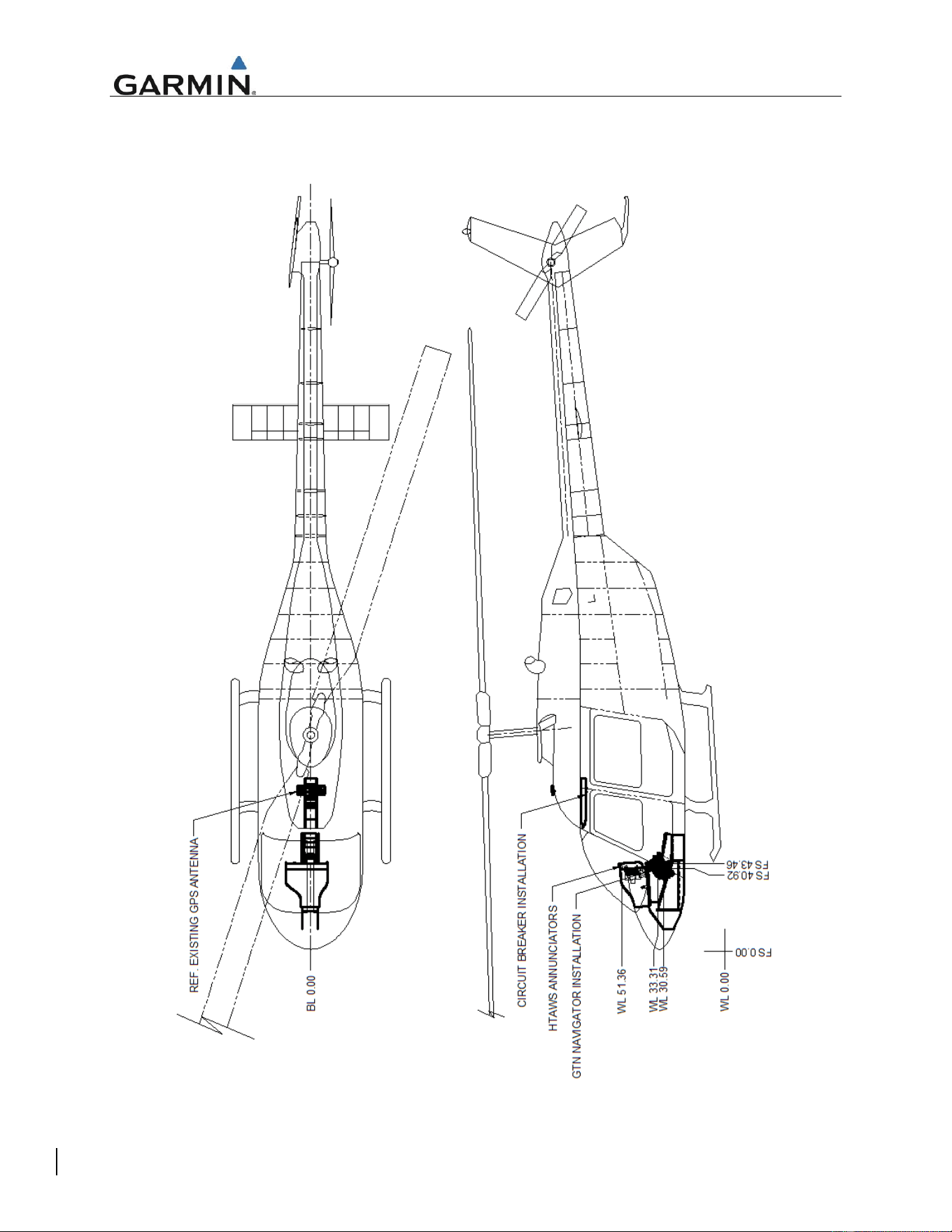
2.8 Equipment Location and Access
Figure 1 depicts the typical location for GTN LRUs, optional GMA 35, and optional HTAWS annunciators.
Figure 1 GTN STC Equipment Fuselage Station Location
Instructions for Continued Airworthiness GTN 6XX/7XX - Bell 206B
Page 10 of 19 190-01007-K3 Rev. 3
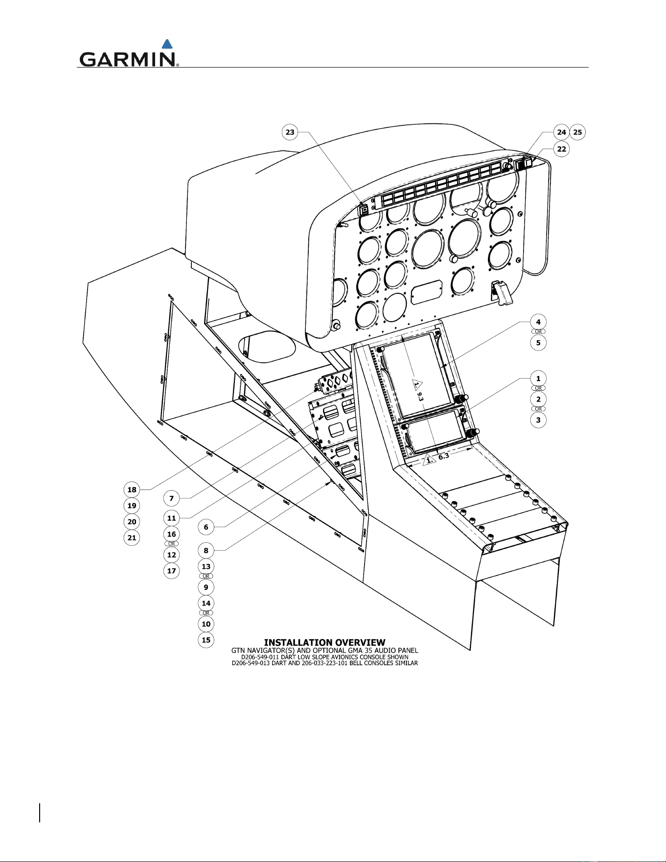
Figure 2 depicts a typical installation as performed in the Bell 206B and reference notations to the bill of
materials. Table 3 provides the bill of materials in reference to Figure 2.
Figure 2 Typical GTN / GMA35 Installation in Bell 206B
Instructions for Continued Airworthiness GTN 6XX/7XX - Bell 206B
Page 11 of 19 190-01007-K3 Rev. 3
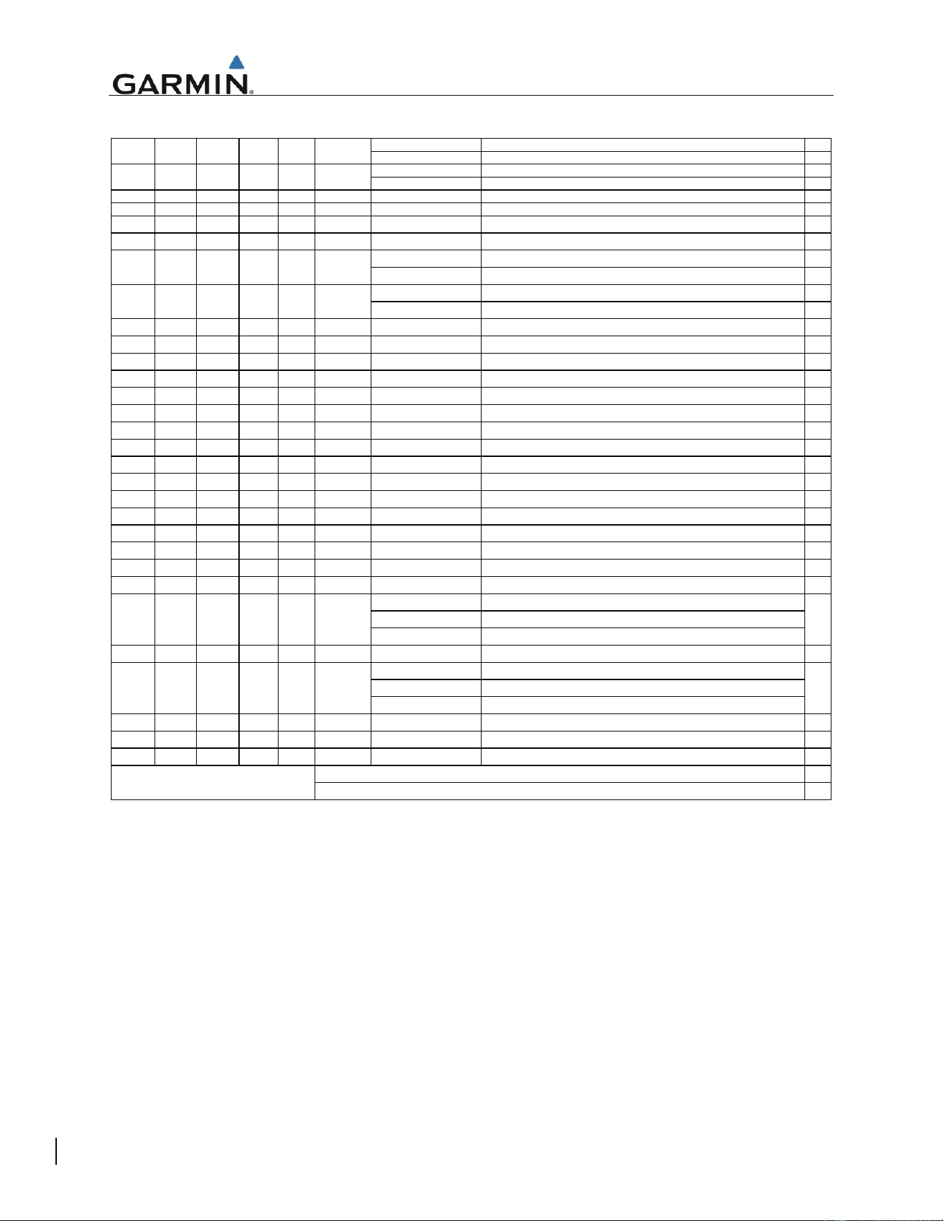
Table 3. Bill of Materials
7277-XX-3 CIRCUIT BREAKER, LOW AMPERAGE, GENERAL APPLICATION, 3 AMP
7274-XX-3 CIRCUIT BREAKER, LOW AMPERAGE, HIGH PERFORMANCE, 3 AMP
7277-XX-5 CIRCUIT BREAKER, LOW AMPERAGE, GENERAL APPLICATION, 5 AMP
7274-XX-5 CIRCUIT BREAKER, LOW AMPERAGE, HIGH PERFORMANCE, 5 AMP
1 1 1 1 1 29 18-440 PLUG, KEYED, QUICK CONNECT
2 2 2 2 2 28 18-200 PLUG, QUICK CONNECT
1 1 1 1 1 25
LED-50-17-11-E14G0 CAP, INDICATOR, HTAWS, STATUS
1 1 1 1 1 24
LED-DM-17-50-BBAKH BODY, DEFINED LOGIC, MFB (O;DL2/NN/UU;0)
LED-41-11-KB-E11RF SWITCH, RP MODE,NVIS
LED-41-11-BB-E11ND SWITCH, RP MODE
LED-40-17-KB-E12XT INDICATOR, HTAWS, CAUTION AND WARNING,NVIS
LED-40-17-BB-E11R9 INDICATOR, HTAWS, CAUTION AND WARNING
-1 -1 - - - 21
011-02302-00 CONNECTOR KIT, GMA 35 AUDIO PANEL
-1 -1 - - - 20
011-02300-00 BACKPLATE SUB-ASSEMBLY, GMA 35 AUDIO PANEL
-1 -1 - - - 19
011-02645-00 INSTALL RACK KIT, GMA 35 AUDIO PANEL
-1 -1 - - - 18
011-02299-00 GMA 35 AUDIO PANEL, REMOTE
1 - - - - 17
011-02326-02 CONNECTOR KIT, GTN 750 NAVIGATOR
- 1 - - - 16
011-02326-00 CONNECTOR KIT, GTN 725 NAVIGATOR
- - 1 - - 15
011-02325-02 CONNECTOR KIT, GTN 650 NAVIGATOR
- - - 1 - 14
011-02325-01 CONNECTOR KIT, GTN 635 NAVIGATOR
- - - - 1 13
011-02325-00 CONNECTOR KIT, GTN 625 NAVIGATOR
1 - 12
011-02246-02 BACKPLATE SUB-ASSEMBLY, GTN 750 NAVIGATOR
- 1 - - - 11
011-02246-00 BACKPLATE SUB-ASSEMBLY, GTN 725 NAVIGATOR
- - 1 - - 10
011-02245-02 BACKPLATE SUB-ASSEMBLY, GTN 650 NAVIGATOR
- - - 1 - 9
011-02245-01 BACKPLATE SUB-ASSEMBLY, GTN 635 NAVIGATOR
- - - - 1 8
011-02245-00 BACKPLATE SUB-ASSEMBLY, GTN 625 NAVIGATOR
1 1 - - - 7
115-01294-A0 MOUNTING RACK, GTN 7XX SERIES NAVIAGATOR, HELICOPTER
- - 1 1 1 6
115-01293-A0 MOUNTING RACK, GTN 6XX SERIES NAVIAGATOR, HELICOPTER
011-02282-A0 GTN 750 TOUCH SCREEN NAVIGATOR, NVIS-B COMPATIBLE
011-02282-50 GTN 750 TOUCH SCREEN NAVIGATOR, GRAY BEZEL
011-02282-00 GTN 750 TOUCH SCREEN NAVIGATOR
- 1 - - - 4
011-02281-00 GTN 725 TOUCH SCREEN NAVIGATOR
011-02256-A0 GTN 650 TOUCH SCREEN NAVIGATOR, NVIS-B COMPATIBLE
011-02256-50 GTN 650 TOUCH SCREEN NAVIGATOR, GRAY BEZEL
011-02256-00 GTN 650 TOUCH SCREEN NAVIGATOR
- - - 1 - 2
011-02255-00 GTN 635 TOUCH SCREEN NAVIGATOR
- - - - 1 1
011-02254-00 GTN 625 TOUCH SCREEN NAVIGATOR
750 725 650 635 625 ITEM NO. PART NUMBER DESCRIPTION
2
31
1
30
2
2
2
2
QTY. PER GTN MODEL
BILL OF MATERIAL
GTN 6XX/7XX NAVIGATOR INSTALLATION
1
-
-
-
-
-
-
1
-
-
23
3
5
OR
OR
22
1
1
1
1
1
1
1
1
1
1
Instructions for Continued Airworthiness GTN 6XX/7XX - Bell 206B
Page 12 of 19 190-01007-K3 Rev. 3
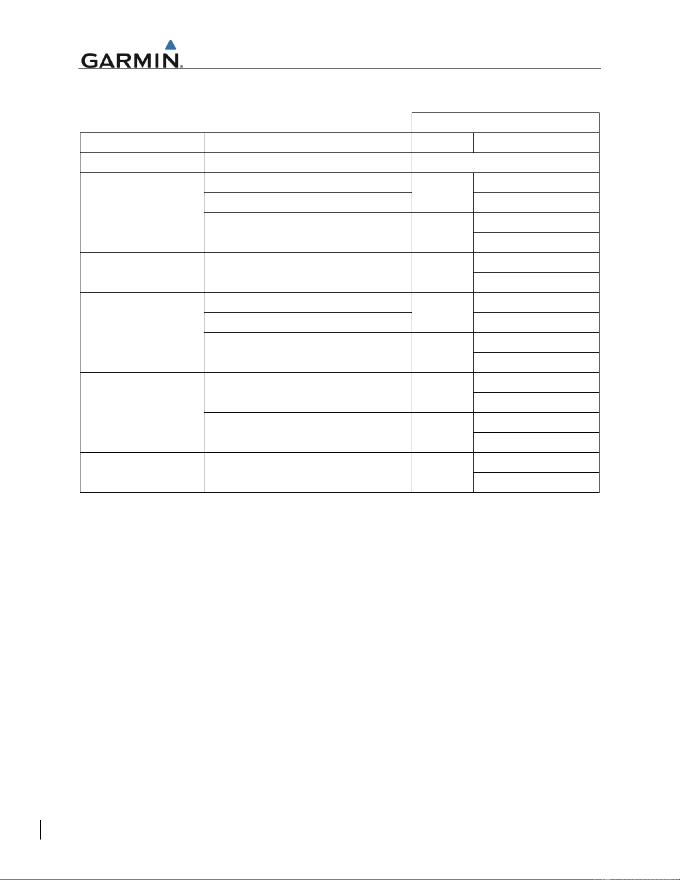
Both GTN and GMA 35 circuit breakers are located on the Bell 206B overhead circuit breaker console.
Equipment circuit breaker placards are labeled as follows:
GTN INSTALLATION
LRU
POWER INPUT
SINGLE
DUAL [1]
GMA 35
Rotorcraft Power on Connector P3502
Audio
GTN 750
Rotorcraft Power on Connector P1001
GPS/NAV
GPS/NAV 1
Rotorcraft Power on Connector P1004
GPS/NAV 2
Rotorcraft Power on Connector P1003
COM
COM 1
COM 2
GTN 725
Rotorcraft Power on Connector P1001
GPS
GPS 1
GPS 2
GTN 650
Rotorcraft Power on Connector P1001
GPS/NAV
GPS/NAV 1
Rotorcraft Power on Connector P1004
GPS/NAV 2
Rotorcraft Power on Connector P1003
COM
COM 1
COM 2
GTN 635
Rotorcraft Power on Connector P1001
GPS
GPS 1
GPS 2
Rotorcraft Power on Connector P1003
COM
COM 1
COM 2
GTN 625
Rotorcraft Power on Connector P1001
GPS
GPS 1
GPS 2
Notes:
[1] Dual installation labeling applies to GTN LRUs only
Instructions for Continued Airworthiness GTN 6XX/7XX - Bell 206B
Page 13 of 19 190-01007-K3 Rev. 3
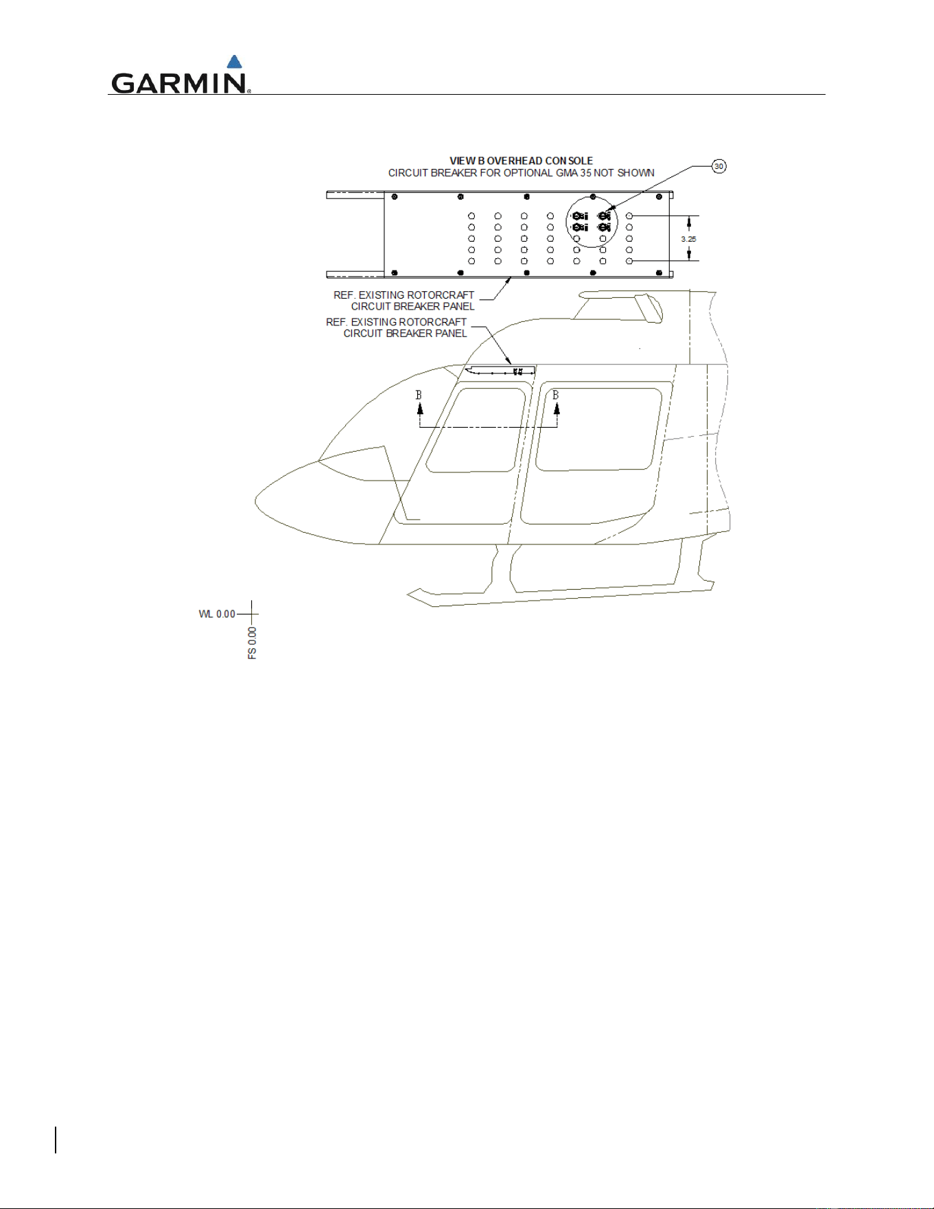
Figure 3 depicts the overhead panel location in the Bell 206B.
Figure 3 Overhead Circuit Breaker Panel in Bell 206B
Instructions for Continued Airworthiness GTN 6XX/7XX - Bell 206B
Page 14 of 19 190-01007-K3 Rev. 3
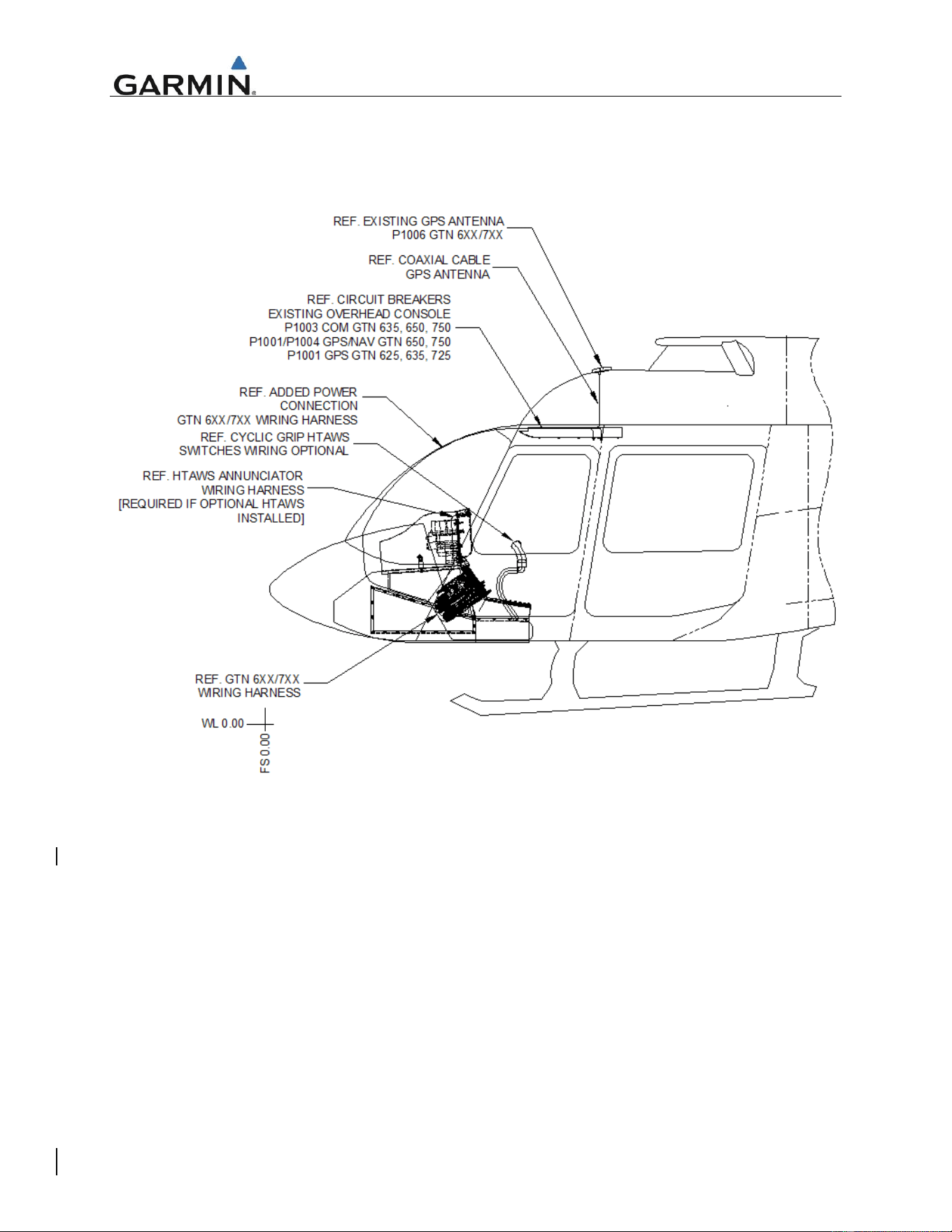
The GTN/GMA 35 wiring harness power and switch connections are routed as shown in Figure 4. Since
the GTNs may be interfaced with preexisting GPS antennas, coaxial wire routing may differ slightly from
the depicted figure. Refer to the aircraft wire routing worksheets and equipment location forms that were
filled out during initial GTN/GMA 35 installation for additional details.
Figure 4 GTN/GMA 35 wire routing in the Bell 206B
GTN/GMA 35 installation racks, backplates, and wiring harnesses may be accessed by either removing
the GTN LRUs as specified in GTN 6XX/7XX PART 27 AML STC MAINTENANCE MANUAL Section 5,
Equipment Removal and Replacement or by removing the side panel of the Bell 206B console. Figure 2
depicts the installation with the side panel removed.
Instructions for Continued Airworthiness GTN 6XX/7XX - Bell 206B
Page 15 of 19 190-01007-K3 Rev. 3
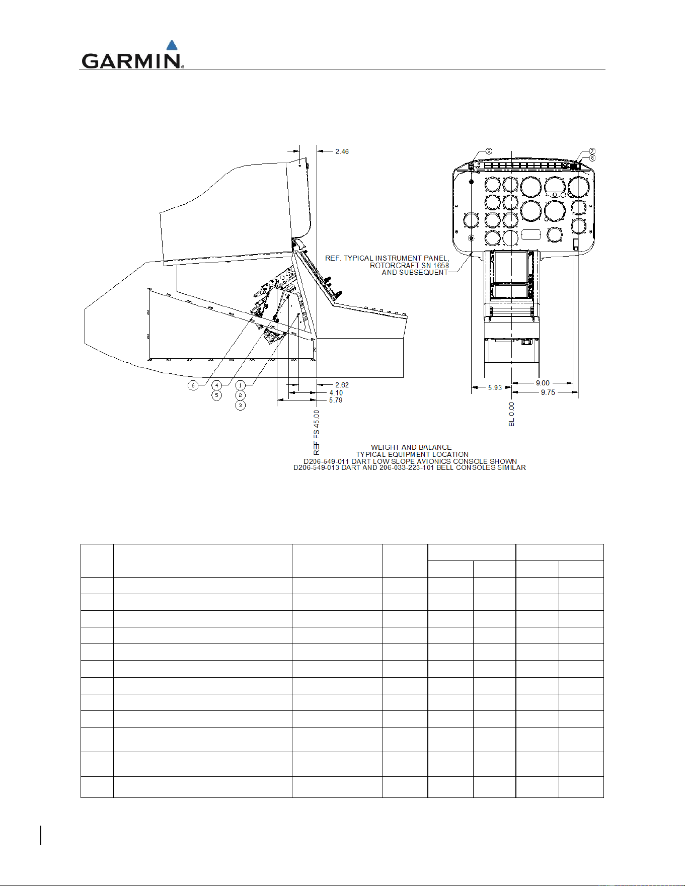
2.9 Weight and Balance
The location of equipment is depicted in Figures 1 and 2. Table 4 provides the weight and moment arm
for equipment in reference to Figure 5.
Figure 5: Equipment Location
Table 4. GTN Equipment Weight and Moment Arm
ITEM
DESCRIPTION
PART NUMBER
WEIGHT
[LBS]
LONGITUDINAL
LATERAL
ARM [IN]
MOMENT
ARM [IN]
MOMENT
1
GTN 625 NAVIGATOR
011-02254-00
6.00
42.48
254.88
0.00
0.00
2
GTN 635 NAVIGATOR
011-02255-00
6.8
42.48
288.86
0.00
0.00
3
GTN 650 NAVIGATOR
011-02256-00
7.6
42.48
322.85
0.00
0.00
4
GTN 725 NAVIGATOR
011-02281-00
8.6
40.90
351.74
0.00
0.00
5
GTN 750 NAVIGATOR
011-02282-00
10.2
40.90
417.18
0.00
0.00
6
GMA 35 REMOTE MOUNT AUDIO PANEL
011-02299-00
2.2
39.21
86.26
0.00
0.00
7
GMA 35 REMOTE MOUNT AUDIO PANEL
011-02299-20
2.1
39.21
82.34
0.00
0.00
8
GMA 35c REMOTE MOUNT AUDIO PANEL
011-02299-40
2.1
39.21
82.34
0.00
0.00
9
FLIGHT STREAM 510
011-03595-00
Negligible
n/a
n/a
n/a
n/a
10
HTAWS CAUTION AND WARNING
INDICATOR
LED-40-17-KB-E12XT
0.06
42.54
2.56
9.00
0.54
11
STATUS ANNUNCIATOR, HTAWS
LED-DM-17-XX-
BBAKH
0.06
42.54
2.56
9.74
0.58
12
RP MODE SWITCH, HTAWS
LED-41-11-BB-
E11ND
0.06
42.54
2.56
-5.93
-0.36

Instructions for Continued Airworthiness GTN 6XX/7XX - Bell 206B
Page 16 of 19 190-01007-K3 Rev. 3
2.10 Diagrams
Aircraft specific LRU locations and wire routing diagram forms are contained in Appendix A of this
document. Completed forms are to be retained with the aircraft permanent records.
Point-to-point wiring diagrams for the GTN, GMA 35, and interfaced equipment included with the aircraft
permanent records.
GTN and GMA 35 locations are described in Section 2.7 of this document.
2.11 Special Inspection Requirements
If an antenna is replaced under this STC, an antenna visual inspection must be performed if there is a
suspected lighting strike on the aircraft. In the event of a suspected or actual lightning strike to the
aircraft, the GPS antenna(s) and its associated installation shall be inspected.
If the antenna was struck by lightning then the antenna and the surrounding installation shall be inspected
to ensure that there is no structural damage around the areas where lightning may have struck. See
Table 2 for inspection criteria.
Execute the system checkout procedure for the GPS/WAAS and/or XM system using the antenna, to
ensure the system(s) are operating correctly.
No action is required for hard landing inspections.
2.12 Application of Protective Treatments
None. N/A.
2.13 Data Relative to Structural Fasteners
Refer to Garmin P/N 190-01007-B1, GTN 6XX/7XX PART 27 AML STC MAINTENANCE MANUAL
Section 5 for fastener information.
2.14 Special Tools
A milliohm meter with an accuracy of +/- 0.1 milliohms ohms (or better) is required to measure the
electrical bonding between the GTN/GMA system components and aircraft ground.
2.15 Additional Instructions
None. N/A
2.16 Overhaul Period
The system does not require overhaul at a specific time period. Power on self-test and continuous BIT will
monitor the health of the GTN system. If any LRU indicates an internal failure, the unit may be removed
and replaced (Refer to Section 5 of the GTN 6XX/7XX PART 27 AML STC MAINTENANCE MANUAL for
Removal and Reinstallation instructions). See GTN 6XX/7XX PART 27 AML STC MAINTENANCE
MANUAL, Section 4 for Troubleshooting information.
2.17 ICA Revision and Distribution
To revise this ICA, Garmin will follow the Garmin ODA Procedures Manual SOP-0055/ACP-0016 for
Instructions for Continued Airworthiness. The latest revision of this ICA document is available on the
Garmin website (www.flyGarmin.com). To Access Aviation Manuals, select the ‘Support’ tab and then
select ‘Manuals’. You may also contact Garmin General Aviation Product Support at 866-739-5687 (US
toll free) 913-397-8200 or avionics@garmin.com. A Garmin Service Bulletin describing ICA revision will
be sent to Garmin dealers if a revision is determined to be significant.

Instructions for Continued Airworthiness GTN 6XX/7XX - Bell 206B
Page 17 of 19 190-01007-K3 Rev. 3
2.18 Assistance
Flight Standards Inspectors or the certificate holder’s PMI have the required resources to respond to
questions regarding this ICA. In addition, the customer may contact Garmin with questions regarding this
equipment and its installation. Garmin Customer Support may be contacted during normal business hours
via telephone 913-397-8200 or from the Garmin web site at www.flyGarmin.com.
2.19 Implementation and Record Keeping
Modification of an aircraft by this Supplemental Type Certificate obligates the aircraft operator to include
the maintenance information provided by this document in the operator’s aircraft maintenance manual
and/or the operator’s rotorcraft scheduled maintenance program.
Instructions for Continued Airworthiness GTN 6XX/7XX - Bell 206B
Page 19 of 19 190-01007-K3 Rev. 3
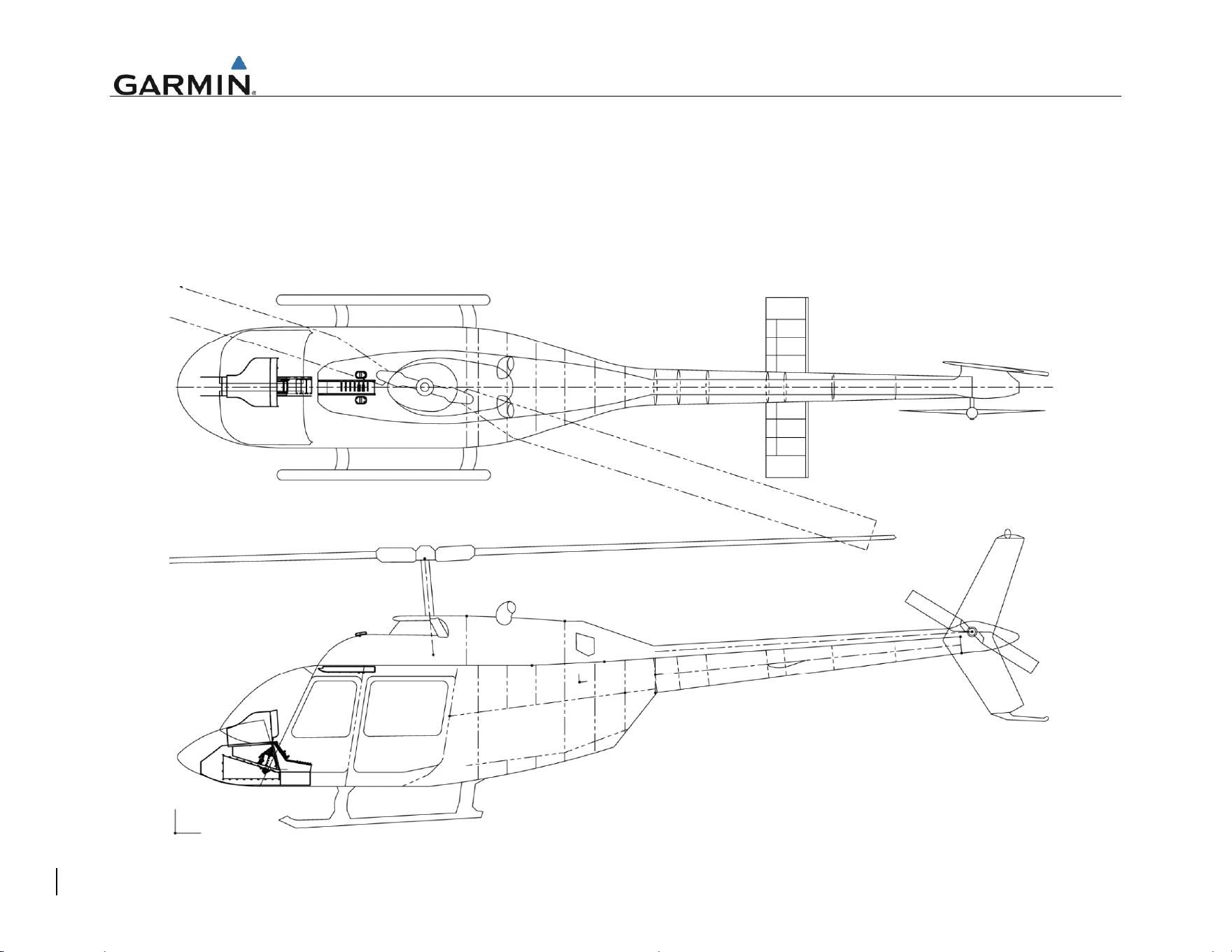
APPENDIX A EQUIPMENT LOCATIONS AND WIRE ROUTING
The following diagram must be completed to depict the location of all LRUs and antenna(s) along with the wire routing for the GTN 6XX/7XX and
GMA 35 throughout the aircraft structure for the Bell 206B rotorcraft. All harnesses fabricated as part of this STC should be included in this
diagram.