OWNER’S GUIDE
COMMERCIAL POWER VENTER KITS
USED IN CONJUNCTION WITH
FLUE DAMPERED COMMERCIAL WATER HEATERS
TABLE OF CONTENTS
Kit Components Table
Page 1
Damper Adjustment
Page 6
Vent Terminal Dimensions
Page 2
Operation Sequence
Page 6
Termination of Vent
Page 2
Trouble Shooting Guide Page 6
Vent Terminal Installation
Page 3
Maintenance
Page 7
Power Venter Installation
Page 3-4
Replacement Parts
Page 7
Power Venter Wiring
Page 5
Warranty
Page 7
PV Kit 4 Vent Hood Template Page 8
CERTIFIED FOR USE ONLY ON COMMERCIAL GAS WATER HEATERS.
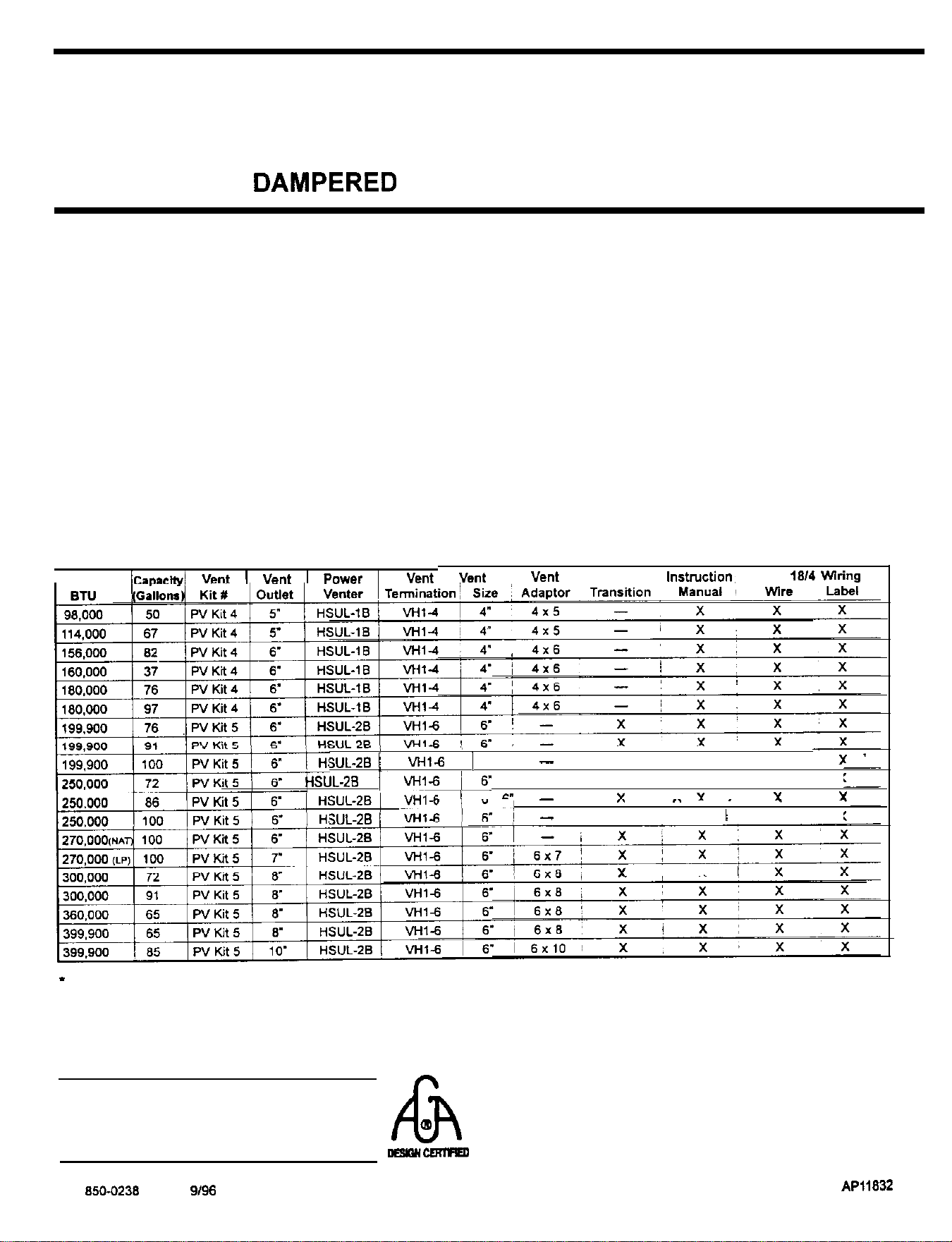
KIT COMPONENTS
I
IcaaaeHvl
Vent
I
ant
I
Power
I
Vent
Vent
:
“en,
outlet
,nstmction,
40 FT
,814
wring
.
-
-
SUL-26
/
wit.6
1
6’
-
X
X
X
,,.sUL-28
/vHldi5.
--
X
X
X
X
/
C”
-
Y Y
Y Y
I/V,
~
I.
,.
.
.
WL-28
/
-
x x
)
x
X
X
i X
*
Note: Vent Pipe and Vent Adapter are NOT included
OWNER’S INSTRUCTIONS
NOTE TO INSTALLER:
THESE INSTRUCTIONS MUST REMAIN
PLEASE READ AND FOLLOW THESE INSTRUCTIONS
CAREFULLY. YOUR INSTALLATION TIME WILL BE
WITH EQUIPMENT
h
0
DO NOT DESTROY
SHORTENED AND PROPER SYSTEM PERFORMANCE
--
AND SAFETY WILL BE ENHANCED.
P/N 850-0238 REV. 2
g/96
1
API1832
A
1
WARNINO
The Venter and Vent Hood must be installed in strjct compliance with these instructions and all
applicable national and local codes and ordinances. Before attempting installation, you must read
and fully understand these instructions. Call your distributor or the manufacturer of the Power
Venter (800-255-4208) if you have any questions regarding proper installation.
’
Installation
A
CAUTION
Failure to follow these installation instructions may violate applicable national and/or local codes.
I.
Check vent’ pipe system for leakage. All vent system leaks must be sealed prior to installation of a
power venter.
2.
The vent system must terminate so that proper clearances are maintained as specified in NFGC,
Sec. 7.3.4. and 7.8. (See section titled “Termination of Vent” in these instructions.)
3.
A vent system incorporating a
VHl
Series Vent Hood should not exceed 550°F.
4.
Termination of a sidewall vent system with a device other than the
VHl
Series Vent Hood could affect
system performance and result in a possible safety hazard.
5.
Plan the vent system layout to avoid the possibility of accidental contact with concealed wiring or
plumbing inside walls.
6.
Installation must be done according to national and local codes.
7.
The setting of the venting proving switch is factory set and should not be adjusted.
8.
The venter should be mounted as close to the vent terminal as is practical.
1
-
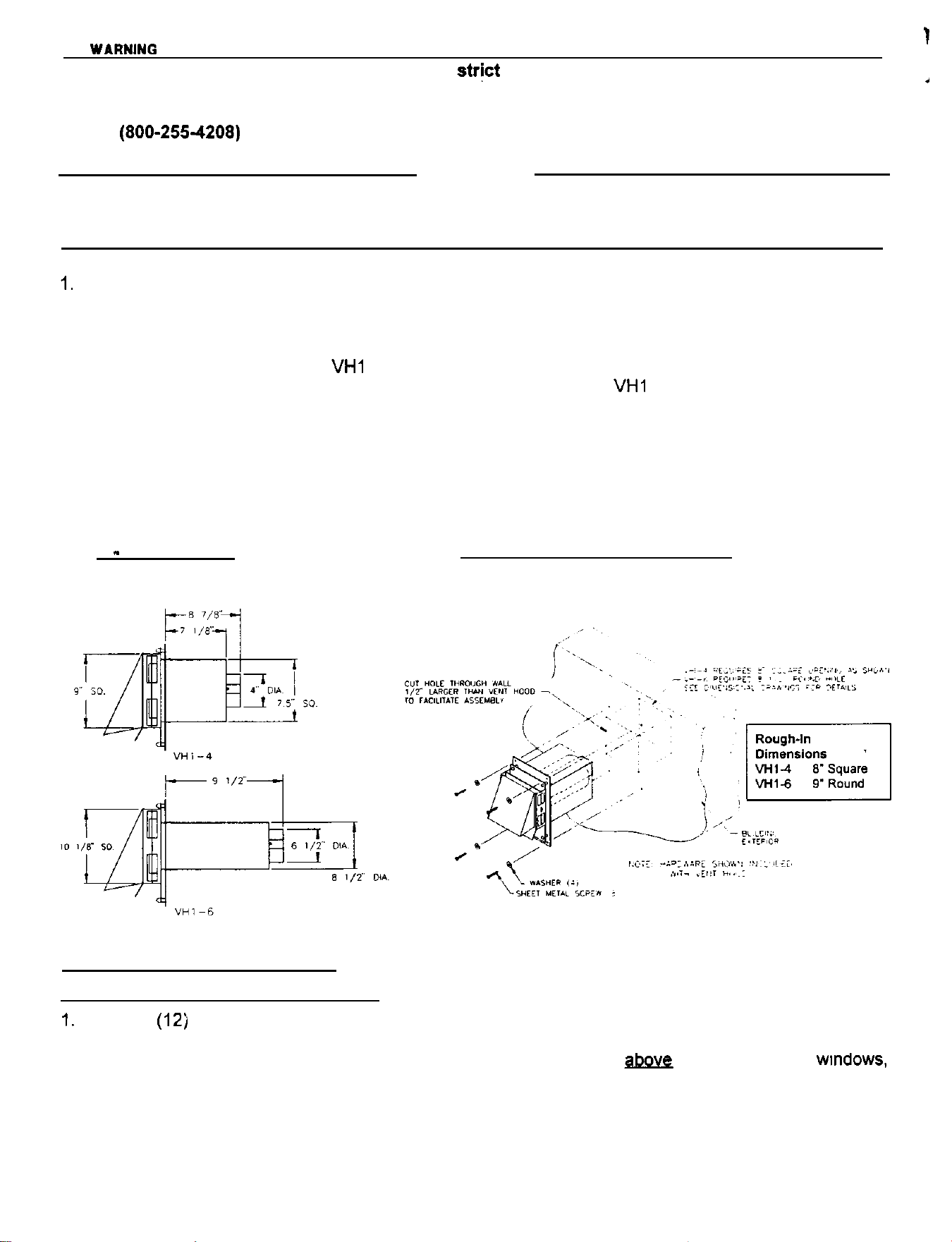
DIMENSIONS
VENT TERMINAL INSTALLATION
2 -TERMINATION OF VENT PIPE
The Vent Terminal Should Be Located;
1.
Twelve (12j inches above grade level and above normal snow levels.
2.
Four (4) feet below, four (4) feet horizontally from any door, window, or gravity air inlet to the building
or other appliances, or from gas or electric meters. DO NOT locate
gpgy6
walkways, doors,
wmdows,
air inlets, gas or electrical meters.
3.
Ten (10) feet from any forced air inlet to the building. Any fresh or make-up air inlet such as for a
dryer or furnace area is considered to be a forced air inlet.
4.
Six (6) feet from an inside comer formed by two exterior walls.
5.
Four (4) feet horizontally from any soffit or under-eave vent.
2
I
3
-
INSTALLATION OF SIDEWAI
r
VFNT TERMINATION THROUGH COMBUSTIBLF WALL
(seediaaramaaae
A
CAUTION
Termination of a sidewall vent system with a device other than the appropriate
VHl
Series Vent
Terminal could affect system performance and result in a possible safety hazard.
A
WARNING
Removal of outer safety pipe on combustible wall installations is extremely hazardous and may
result in fire or personal injury or property damage.
a)
W
4
d)
e)
a)
b)
c)
d)
For Power Vent Kit 4:
Attach the enclosed template on Page 6 to interior of the wall the Vent Hood will be penetrating.
Using a
l/2”
drill bit, drill two pilot holes where noted on the template. The drill bit must be long
enough to penetrate to the building exterior.
Attach template to the building exterior aligning the pilot holes noted on the template with the holes
drilled in step A.
Using a reciprocating saw, cut a hole through the building siding, wall board, etc., following the appro-
priate lines of the template.
Slide the Vent Hood through the opening and fasten to exterior wall using screws provided.
Once Power Venter and vent pipe are completely installed and secured, apply a bead of caulk
between the Vent Hood flange and exterior of building.
For Power Vent Kit 5:
Use inside wall cover plate as a template to mark a hole at termination point on the wall. Cut hole
112”
larger than cover plate to facilitate installation.
Slide Vent Hood through opening. Fasten to exterior wall using screws provided.
Install cover plate and fasten to the inside wall with four screws.
Once Power Venter and vent pipe are completely installed and secured, apply a bead of caulk
between the Vent Hood flange and exterior of building.
4
-
POWER VENTER INSTALLATION PROCEDURE
A
CAUTION
1.
2.
3.
4.
5.
6.
7.
a.
9.
a)
b)
Disconnect power supply before making wiring connection to prevent electrical shock and equipment
damage.
All wiring must comply with applicable national and local codes and ordinances.
When wiring is completed check all components by running system through at least three heating
cycles.
Flue temperature must not exceed 550°F at power venter inlet.
Power Venter damper must be adjusted to assure appliance
efficiency
is not affected. See heading
“Damper Adjustment”.
Failure to install, maintain and/or operate the power venter in accordance with the manufacturer’s
instructions may result in a safety hazard or conditions which can produce personal injury and/or
property damage.
Maintain 6” clearance to combustibles from power vent housing.
Use only single wall metal or type ‘B’ vent.
If you have any questions regarding proper installation of the Power Venter or safety precautions, call
the manufacturer of the Power Venter
(600-2554206).
Verify Power Venter model selection from chart on page
1.
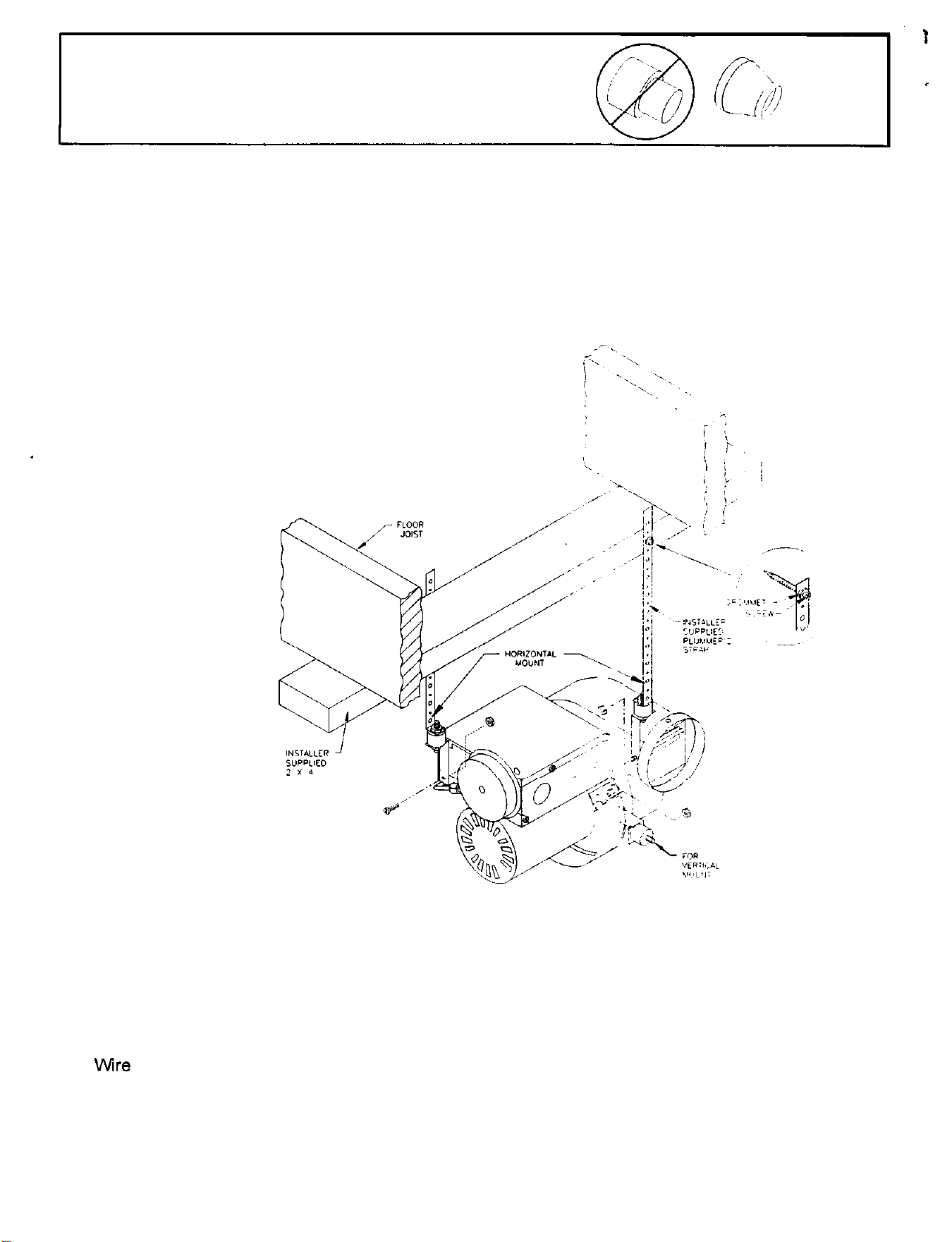
Connect outlet of Power Venter to vent terminal, suspending the Power Venter to joists, or other ade-
quate support means, as shown in following diagram. NOTE: Venter outlet may be horizontal or verti-
cal as long as the oil holes are level or point upward.
VENTER MUST BE MOUNTED WITH MOTOR SHAFT HORIZONTAL.
3
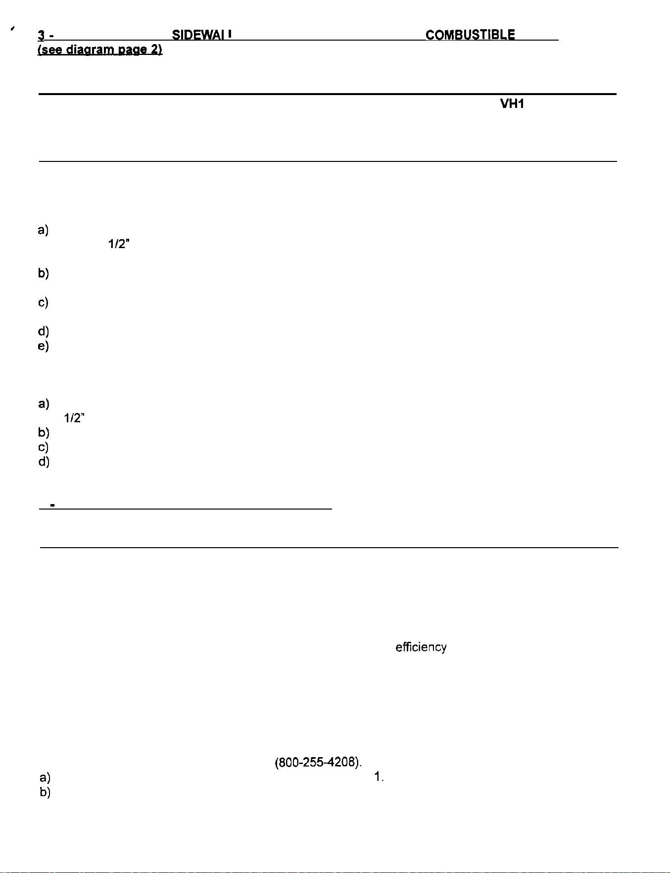
NOTE: Vent pipe transitions, where necessary,
must be gradually tapered.
To facilitate installation and reduce vibration, the vent kit includes 2 mounting brackets, 2 rubber isolators
and 2 rubber grommets. One of the brackets may be used temporarily as a “third hand” to support the
venter while positioning it for permanent installation.
When installing the Power Venter for horizontal mount, install one of the brackets to the electrical box
using the nut/screw provided, install the other bracket to the damper rod as shown below. When installing
the Power Venter for vertical mount, only one bracket is needed. This bracket should be mounted to the
motor mount as shown below.
NOTE: Whether horizontal or
vertical mount, the motor shaft
must be horizontal.
c)
Connect the inlet of the Power Venter to the Draft Hood of the appliance outlet using suitable vent pip-
ing and adapter if required (not supplied in the vent kit). This Power Venter can be installed with a
maximum of 50 linear feet of single wall vent pipe including the vent terminal. Deduct 10 feet of vent
pipe for each 90 degree elbow and 8 feet for each 45 degree elbow to determine the total amount of
linear vent pipe allowed for the installation.
d)
It is recommended all vent connections should be sealed to prevent leaks after installation using high
temperature silicone sealant.
e)
Wire
Power Venter according to appropriate circuit appearing below. Unit must be grounded, all wiring
is to comply with applicable electrical codes. Wring must be protected by overcurrent protection
(fuses or circuit breakers) rated 15 amperes or less. Extreme caution must be exercised to ensure
that wiring does not come into contact with any heat source.
4
Wire the Power Venter to the circuit appearing below. Venter must be gmunded. All wiring is to comply
with applicable electrical codes. Wiring must be protected by fuses or circuit breaker rated
16
amps or
less. Extreme caution must be exercised to ensure that witins does not contact anv heat source.
“%
-ASl.
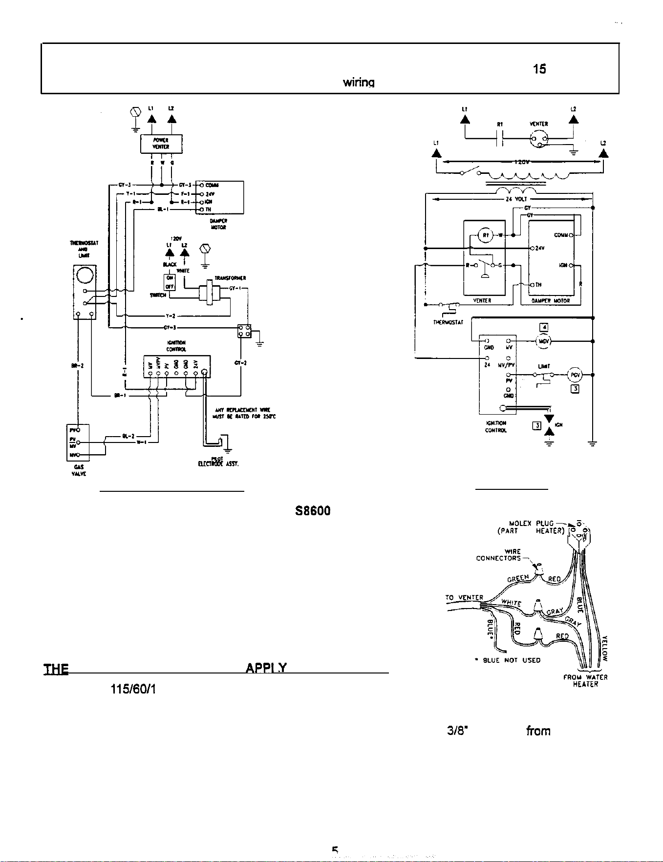
CONNECTION DIAGRAM
SCHEMATIC
HONEYWELL
S8600
IGNITION CONTROL
MOLEX
PLUG-&s,,
(PART
OF
uEarER,
IfiE
FOLLOWING INSTRUCTIONS
APPt
Y
TO AL’ MODELS
1.
Supply 115/60/l power to the venter supply connections.
2.
Locate the wire harness that connects to the flue damper motor. This consists of a red, gray, yellow
and blue wire connected to a Molex 4 pin plug.
3.
Cut the red and gray wires approximately 3’ before the plug and strip
3/8’
insulation
Tom
all wire
ends created by cuts.
4.
Connect the red wire from the water heater to the red wire on the venter cable.
5.
Connect the red wire from the Molex plug to the green wire on the venter cable.
6.
Join the gray wire from the water heater to both the gray wire from the Molex plug and the white wire
on the venter cable.
7.
Affix new wiring label over existing wiring label on heater.
Slowly close damper on venter discharge until flue gas spillage is detected
at
the
draf?
hood. Open
damper just enough to eliminate spillage. Lock damper in place by means of locknut on opposite side of
housing.
Operation
1.
On a call for heat from the control thermostat, 24 volts is applied to the actuating terminal of the
damper motor.
2.
When the damper motor is fully open, power is applied to the 24 volt relay of the venter.
3.
When the venter motor has started, the air proving switch allows the main gas valve to open.
4.
When the thermostat is satisfied, power is removed from the actuating terminal of the damper motor.
5.
As the damper begins to close, power is removed from the venter relay, the venter shuts down, the air
proving switch opens, and the gas valve closes.
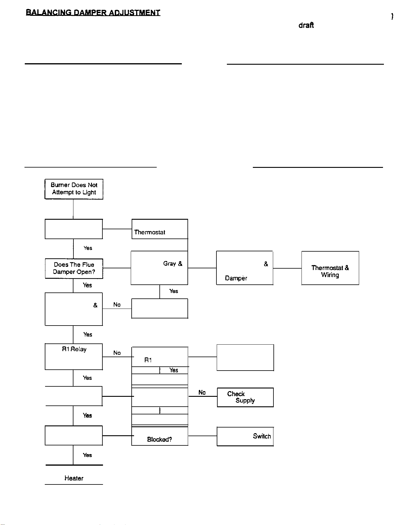
Trouble Shooting Guide
Burner Does
Not
Attempt to Light
.
L
I
Is The Thermostat
N
O
Increase
Calling For Heat?
Then&at
Setting
Yes
Is There 24 VAC
Between Gray
&
Red Wires At
Damper Plug?
NO
NO
Is There 24 VAC
Between
Gray
B
Blue Wires At
Damper Plug?
Yes
Replace Damper
Motor
NO
Is There 24 VAC
Between Gray
&
Yellow Wires At
Damper Plug?
NO
Check Transformer
lllenostat
8
Witing
Is Rl
Relay
I”
Power Venter
Energized?
Yes
Is Power Venter
Motor Running?
YM
NO
NO
Is There 24 VAC
On Rl Relay Coil?
1
Yes
Replace Relay
Is There 115 VAC
on Venter Motor?
1
Yes
Replace Motor
NO
Check Wiring From
Damper End
Switch
NO
Check
Power
SUPPly
Is Air Proving
Switch Made?
YeS
NO
Is Vent Pipe
BlOCked?
NO
Replace Air
Switch
Check Wiring to
Heater
6
.
.
Maintenance
1.
Motor should be lubricated every six months with 4 drops of SAE 20 oil, non detergent type.
2.
Vent
terrninaticm
screen should be kept clean and free of debris.
3.
Venter wheel must be clear of any coating which inhibits either rotation or air flow. Remove all foreign
material before operating.
Replacement Parts
Replacement parts are available from your Tjemlund distributor. For more infonation contact Tjernlund
Products, Inc. at l-800-255-4208.
For Power Vent Kit 4:
Motor Kit
Fan Proving Switch Kit
Relay Kit
Wheel Kit
Tjernlund
!!!arsB
950-l 020
950-I 030
950-l 040
950-1011
For Power Vent Kit 5:
Motor
W/
Wheel Kit
Fan Proving Switch Kit
Relay Kit
Wheel Kit
318”
Bore
Tjernlund
Part
950-I 021
950-I 031
950-l
040
950-1012
Warranty
How to Obtain Service Assistance
I.
Should you have any questions about your new Power Venter or if it requires adjustment, repair, or
routine maintenance, it is suggested that you first contact your installer, plumbing contractor or previ-
ously agreed upon service agency. In the event that the
firm
has moved, or is unavailable, refer to the
telephone directory commercial listings or local utility for qualified service assistance.
2.
Should your problem not be solved to your complete satisfaction, you should then contact the
Manufacturer at l-800-255-4208.
When contacting the manufacturer of the Power Venter, the following information should be made avail-
able:
1.
Model number of the Power Venter as shown on the label attached to the Power Venter.
2.
Address where Power Venter is located and can be seen.
3.
Name and address of installer and any service agency who perfoned service on the Power Venter.
4.
Date of original installation and dates any service work was perfoned.
5.
Details of the problem as you can best describe them.
6.
List of people, with dates, who have been contacted regarding your problem.
7
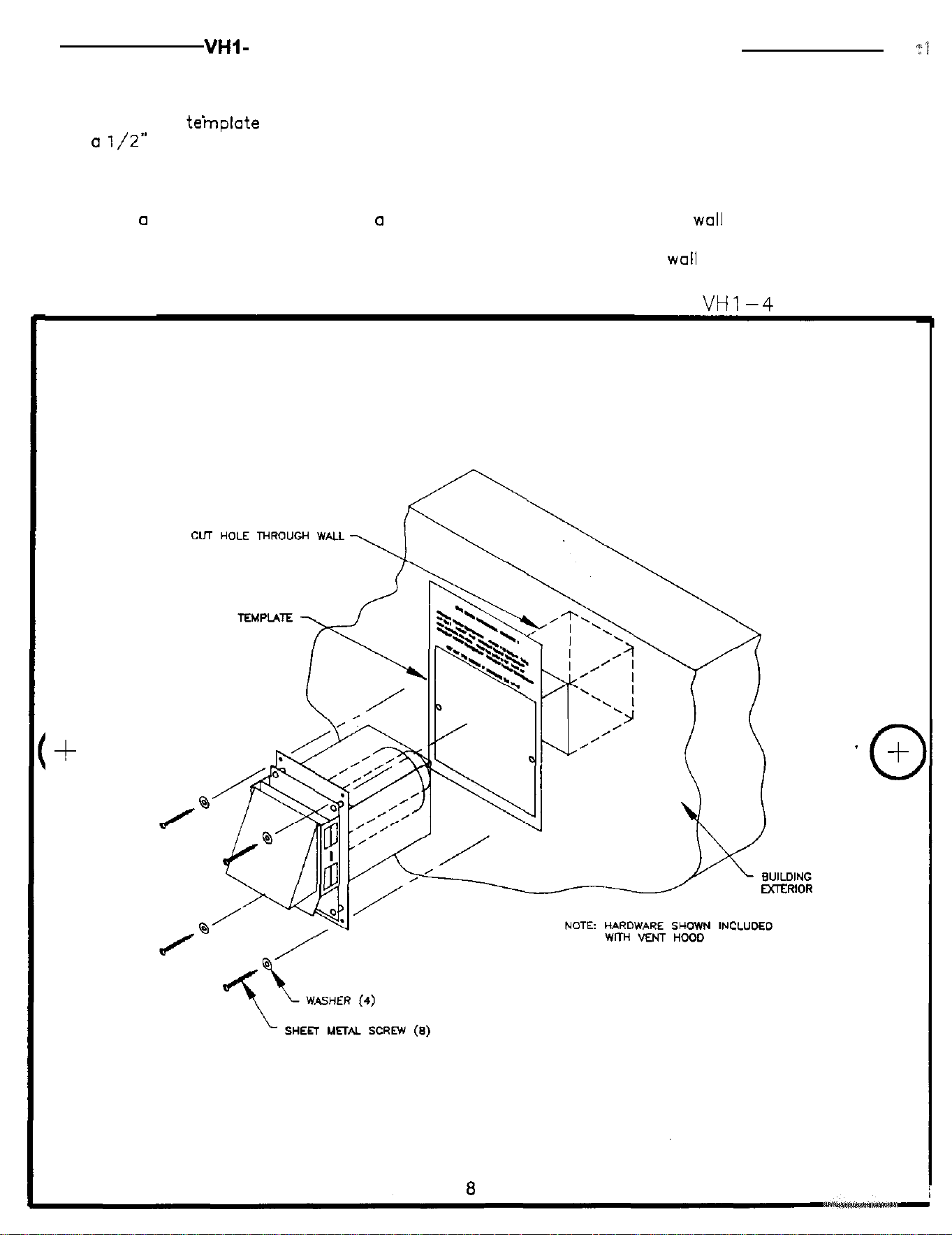
VHl-
4 Vent Hood Mounting Template for Power Vent Kit # 4
:1
This template is to be used in Vent Hood installation section of the installation instructions. .
1. Attach this
teinplote
to the interior of the wall the vent hood will be penetrating. Using
a
l/Z”
drill bit, drill two pilot holes where noted on the template. The drill bit must be
long enough to penetrate the building exterior.
2. Attach this template to the building exterior aligning the pilot holes on the template with
the pilot holes drilled in step 1.
3. Using
0
reciprocating saw, cut
CI
hole through the building siding,
wall
board, etc., following
the appropriate lines of this template.
4. Slide the vent hood through the opening and fasten to exterior
wall
using provided screws,
CUT OUT THIS SQUARE WHEN INSTALLING THE
VHl-4
PILOT
HOLE
3
+
PILOT
HOLE