MILWAUKEE TOOL
l
www.milwaukeetool.com
13135 W. Lisbon Road, Brookeld, WI 53005
Drwg. 1
BULLETIN NO.
54-07-9005
SERVICE PARTS LIST
CATALOG NO. MXF010
REVISED BULLETIN
SPECIFY CATALOG NO. AND SERIAL NO. WHEN ORDERING PARTS
MX FUEL™ PORTABLE BATTERY EXTENSION
SERIAL NO.
DATE
July 2024
WIRING INSTRUCTION
P08A
See Page 5
Only maintenance, service, repairs, and replacements of parts as dened
in the Operator's Manual can be performed by the user.
All other repairs are to ONLY be performed by personnel authorized by
MILWAUKEE TOOL. Do not attempt to install other parts; this COULD void your tool warranty.
For service, parts, or inquiries, contact us:
• Customer Service at 1.800.SAWDUST (1.800.729.3878)
• E-Service tool repair at: www.milwaukeetool.com/e-service
• Find a local authorized MILWAUKEE service location at Milwaukeetool.com
• Find a MILWAUKEE factory Service Center Location or MILWAUKEE factory Central Repair Center at
Milwaukeetool.com. Send the following, posted paid and insured:
• Your name, address, and phone number
• Description of the issues
• Copy of the proof of purchase
• Tool, charger, and batteries involved with the issues
MILWAUKEE factory Central Repair Centers:
MILWAUKEE TOOL MILWAUKEE TOOL
Central Repair Central Repair
1401 Sycamore Avenue 2198 Southtech Drive
Greenwood, MS 38930 Greenwood, IN 46143
SUB ASSEMBLY LISTING PAGE 2
QUICK RELEASE BACKPLATE PAGE 2
CONSOLE HOUSING ASSEMBLY PAGE 3
MOCK BATTERY ASSEMBLY PAGE 4
TORQUE SPECIFICATION CHART PAGE 4
WIRING PAGE 5
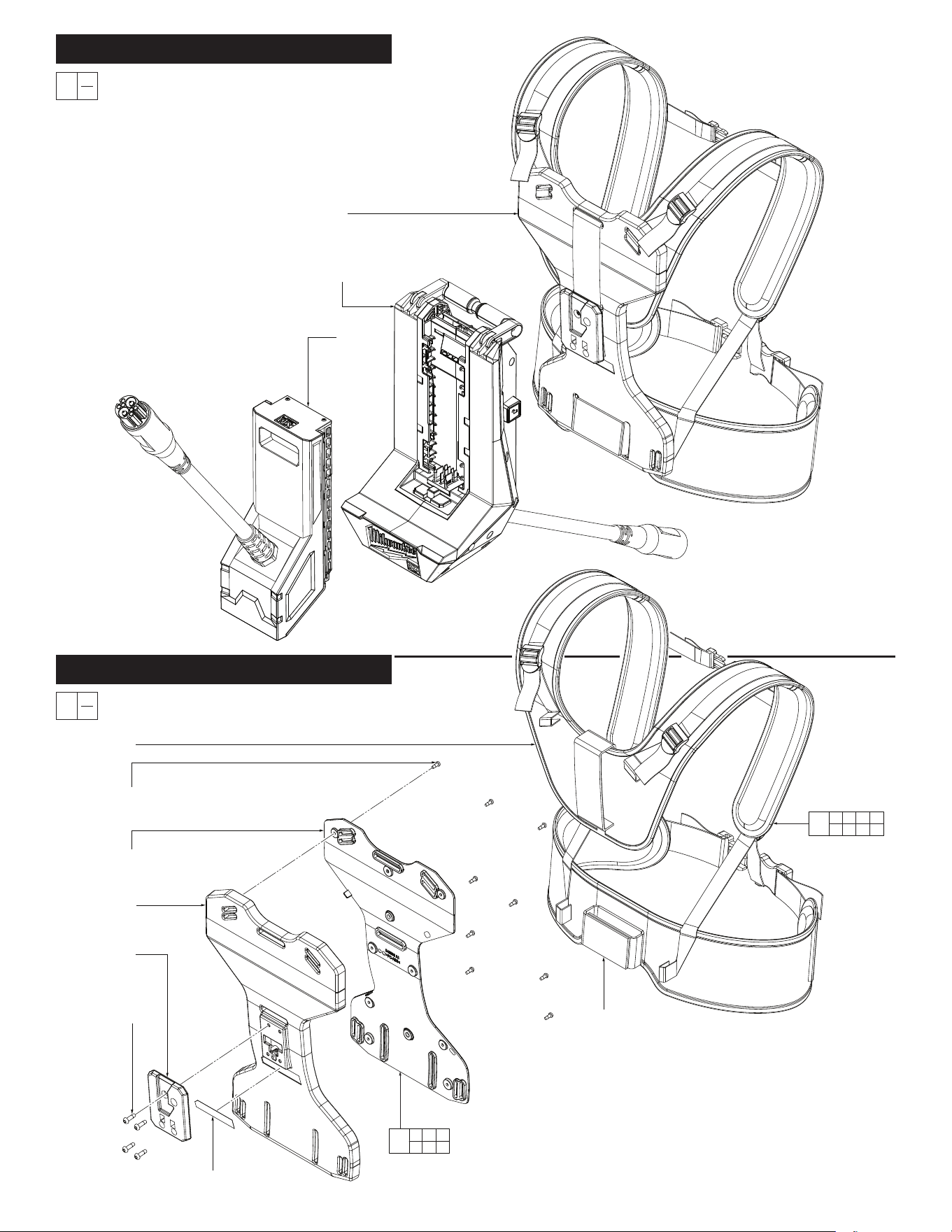
FIG. PART NO. DESCRIPTION OF PART NO. REQ.
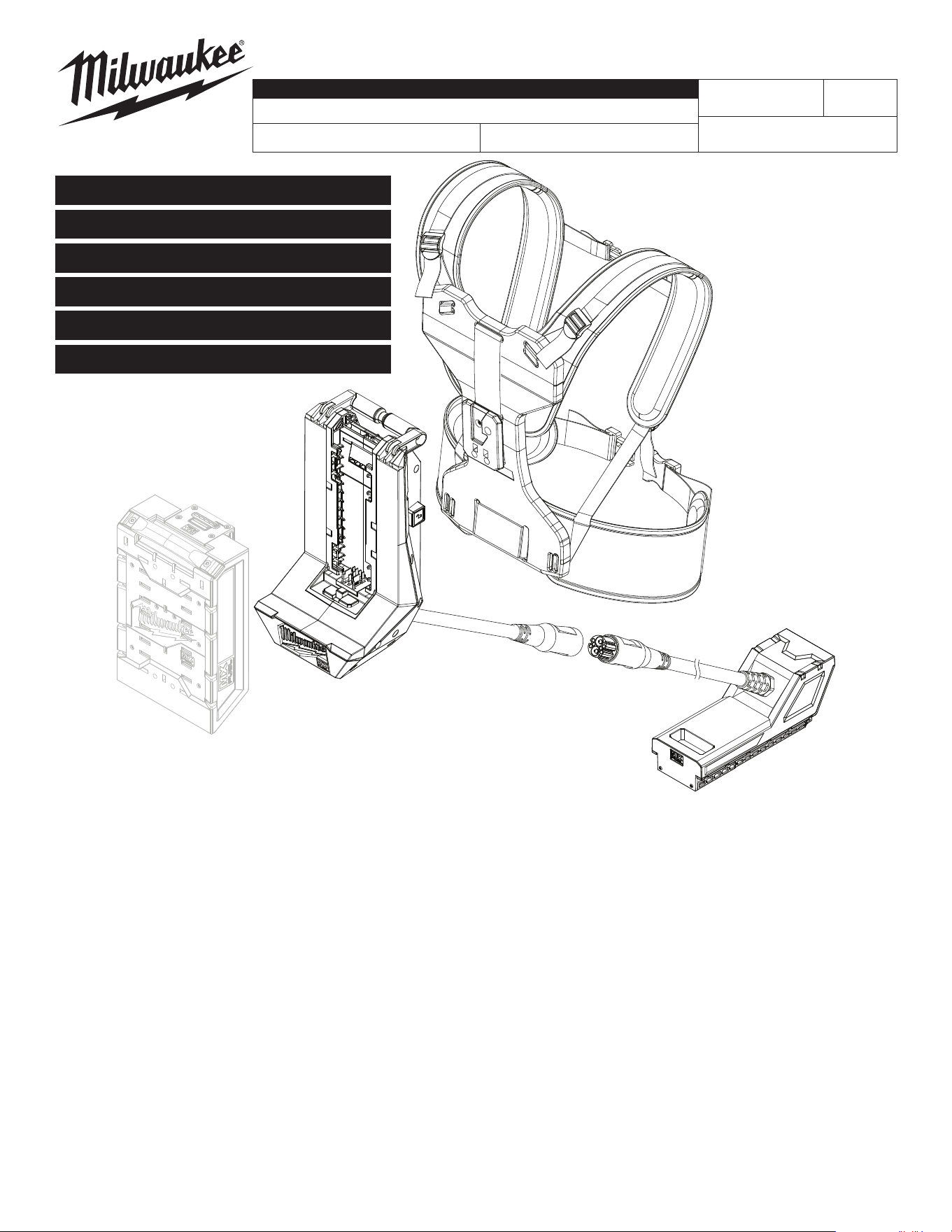
1 --------------- MX FUEL Console Housing, See Page 3 (1)
2 1008 MX FUEL Mock Battery, See Page 4 (1)
3 1000 MX FUEL Backpack Harness, See Below (1)
0
00
EXAMPLE:
Component Parts (Small #) Are Included
When Ordering The Assembly (Large #).
SUB ASSEMBLY LISTING PAGE 2
3
1
2
FIG. PART NO. DESCRIPTION OF PART NO. REQ.
1 06-82-0029 M5 x 16mm Pan Hd. ST T-25 Screw (4)
2 --------------- Backpack Attachment - Back Side (1)
3 1000 Quick Release Backplate Assembly (1)
4 --------------- Backplate Shell (1)
5 --------------- Backplate Cover (1)
6 05-88-1220 M4 x 10mm Pan Hd. ST T-20 Screw (9)
7 45-56-5525 Backpack Harness (1)
8 45-56-5535 Waist Belt (1)
9 12-20-9953 Service Nameplate (1)
10 14-46-9420 Backplate Service Assembly (1)
QUICK RELEASE BACKPLATE PAGE 2
0
00
EXAMPLE:
Component Parts (Small #) Are Included
When Ordering The Assembly (Large #).
7
6
(9x)
5
4
2
1
(4x)
9
8
10
1 2 4
5 6 9
3
1 2 4 5
6 7 8 9
0
00
EXAMPLE:
Component Parts (Small #) Are Included
When Ordering The Assembly (Large #).
FIG. PART NO. DESCRIPTION OF PART NO. REQ.
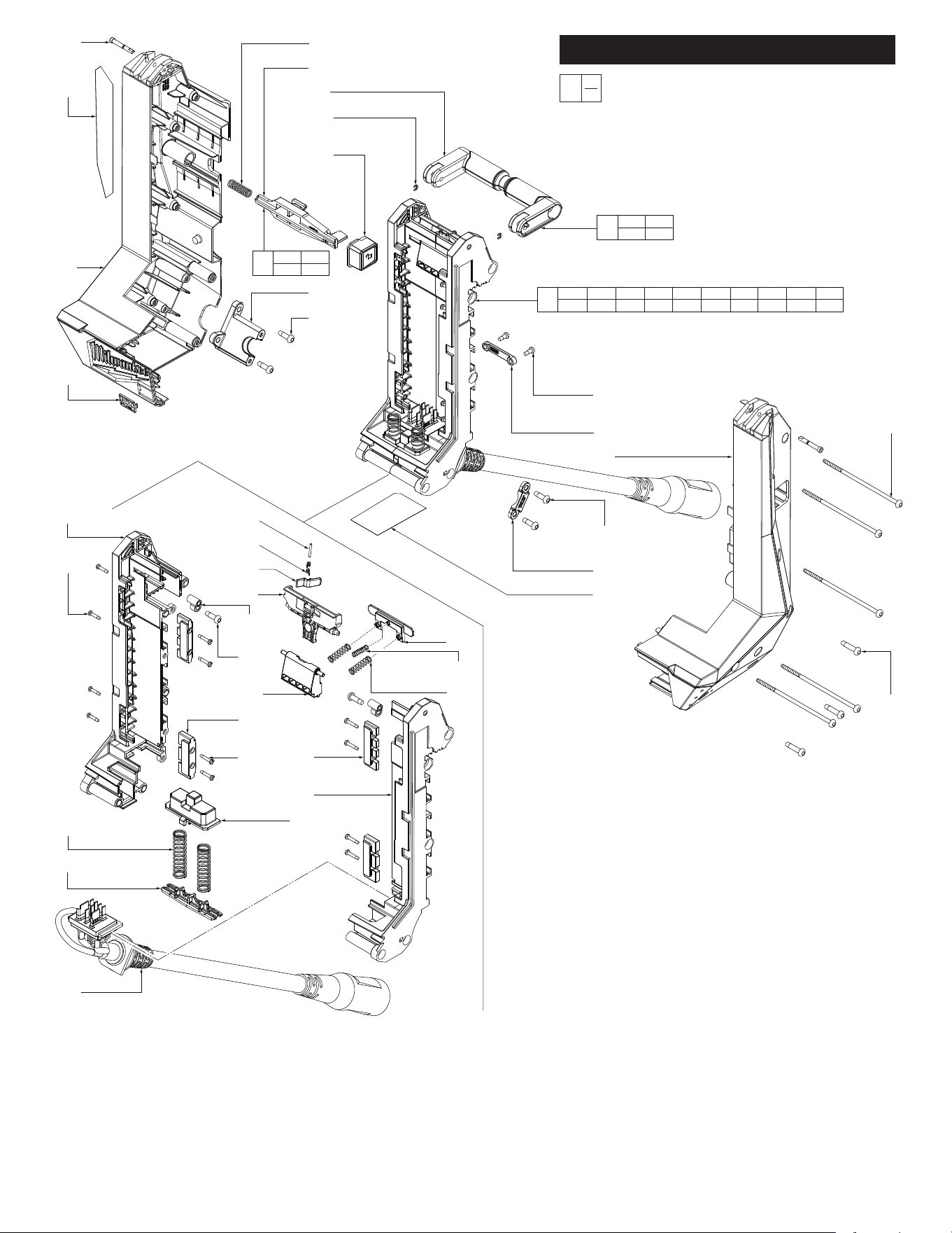
1a 14-20-9355 MX FUEL Battery Rail Service Assembly (1)
1-1 28-20-7020 Housing Cover (1)
1-2 28-50-7870 Housing Support (1)
1-3 31-01-9120 Logo Plate (1)
1-4 --------------- Folding Handle (1)
1-5 --------------- Lever Lockout (1)
1-6 --------------- Torsion Spring (1)
1-7 --------------- Release Lever (1)
1-8 --------------- Lock O Lever Pin (1)
1-9 --------------- Spring (2)
1-10 --------------- M3 x 14mm Pan Hd. ST T-10 Screw (4)
CONSOLE HOUSING ASSEMBLY PAGE 3
FIG. PART NO. DESCRIPTION OF PART NO. REQ.
1-11 --------------- Spring (2)
1-12 --------------- Battery Ejector (1)
1-13 --------------- Pivot Latch Spring Holder (1)
1-14 --------------- Ejector Spring Holder (1)
1-15 --------------- Pivot Bushing (2)
1-16 --------------- M5 x 16mm Pan Hd. ST T-25 Screw (2)
1-17 --------------- Rear Metal Rail (2)
1-18 --------------- Front Metal Rail (2)
1-19 --------------- Spring (1)
1-20 --------------- M3 x 16mm Pan Hd. ST TP Screw (8)
1-21 --------------- Right Battery Rail (1)
1-22 --------------- Left Battery Rail with Slot (1)
1-23 --------------- Pivot Latch (1)
1-24 05-88-0087 M5 x 115mm Pan Hd. PT T-20 Screw (5)
1-25 --------------- Locking Pin (1)
1-26 --------------- Compression Spring (1)
1-27 06-82-0152 M5 x 22mm Pan Hd. ST T-25 Screw (3)
1-28 06-82-0029 M5 x 16mm Pan Hd. ST T-25 Screw (4)
1-29 --------------- Release Button (1)
1-30 28-10-0880 Wire Clamp (1)
1-31 22-56-9120 Wire Clamp Support (1)
1-32 --------------- Terminal Block Assembly (1)
1-33 06-65-7550 Pin (2)
1-34 34-60-0401 E-Ring (2)
1-36 10-22-0589 Warning Label (1)
1-37 45-88-9315 Plastic Washer (1)
1-38 05-88-1220 M4 x 10mm Pan Hd. ST T-20 Screw (2)
1-39 12-20-9950 Service Nameplate (1)
20 14-46-9973 Ejector Pin Service Kit (1)
21 14-46-9974 Lift Handle Service Kit (1)
1-33
(2x)
1-36
1-2
1-3
1-22
1-10
(4x)
1-9
(2x)
1-14
1-32
1-8
1-6
1-5
1-7
1-15
(2x)
1-16
(2x)
1-23
1-18
(2x)
1-20
(8x)
1-17
(2x)
1-21
1-12
1-38
(2x)
1-37
1-1
1-28
(2x)
1-30
1-39
1-24
(5x)
1-27
(3x)
1-13
1-19
1-11
(2x)
1-26
1-25
1-4
1-34
(2x)
1-29
1-31
1-28
(2x)
1a
1-5 1-6 1-7 1-8 1-9 1-10 1-11 1-12 1-13 1-14
1-15 1-16 1-17 1-18 1-19 1-20 1-21 1-22 1-23 1-32
20
1-25 1-26
1-29
21
1-4 1-33
1-34
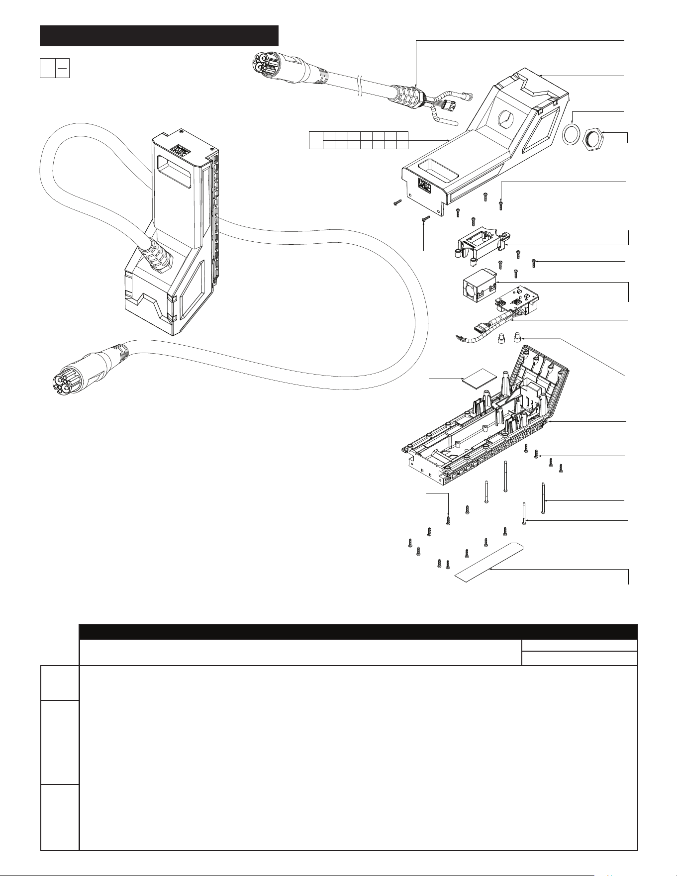
FIG. PART NO. DESCRIPTION OF PART NO. REQ.
1 --------------- Mock Battery Bottom Housing (1)
2 --------------- Mock Battery Top Housing (1)
3 --------------- M3 x 12mm Pan Hd. Taptite T-10 Screw (24)
4 --------------- M3 x 38mm Pan Hd. ST T-10 Screw (2)
5 --------------- M6 x 7mm Cap Hd. Hex Drive Machine Scr. (2)
6 --------------- M3 x 55mm Pan Hd. ST T-10 Screw (2)
7 --------------- Mock Battery Cable Assembly (1)
8 --------------- Mock Battery PCBA (1)
9 --------------- M24 x 1.5 Plastic Hex Nut (1)
10 --------------- Rubber Washer (1)
11 --------------- Ferrite (1)
12 --------------- Ferrite Holder (1)
13 --------------- Foam Pad for Ferrite (1)
15 12-20-9957 Service Nameplate (1)
16 1008 Mock Battery Assembly (1)
0
00
EXAMPLE:
Component Parts (Small #) Are Included
When Ordering The Assembly (Large #).
MOCK BATTERY ASSEMBLY PAGE 4
7
2
10
9
3
(4x)
12
3
(4x)
11
8
5
(2x)
1
3
(4x)
6
(2x)
4
(2x)
15
3
(2x)
13
3
(10x)
1 2 3 4 5 6 7
8 9 10 11 12 13 15
16
SCREW TORQUE SPECIFICATIONS
SEAT TORQUE
FIG. PART NO. DESCRIPTION OF FASTENER WHERE USED (lb-in) (kgf-cm)
1 06-82-0029 M5 x 16mm Pan Hd. ST T-25 Screw Backpack Attachment - Back Side 19.9-23.4 23-27
6 05-88-1220 M4 x 10mm Pan Hd. ST T-20 Screw Backplate Cover 8.6-10.4 10-12
1-10 --------------- M3 x 14mm Pan Hd. ST T-10 Screw Left Battery Rail with Slot 6.0-7.8 7-9
1-16 --------------- M5 x 16mm Pan Hd. ST T-25 Screw Pivot Bushing 13.0-16.4 15-19
1-20 --------------- M3 x 16mm Pan Hd. ST TP Screw Front and Rear Metal Rails 6.0-7.8 7-9
1-24 05-88-0087 M5 x 115mm Pan Hd. PT T-20 Screw Housing Cover 19.9-23.4 23-27
1-27 06-82-0152 M5 x 22mm Pan Hd. ST T-25 Screw Housing Cover 19.9-23.4 23-27
1-28 06-82-0029 M5 x 16mm Pan Hd. ST T-25 Screw Wire Clamp, Wire Clamp Support 19.9-23.4 23-24
1-38 05-88-1220 M4 x 10mm Pan Hd. ST T-20 Screw Plastic Washer 5.2-6.9 6-8
3 --------------- M3 x 12mm Pan Hd. Taptite T-10 Screw Top Hsg., Ferrite Holder, PCBA, Bot. Hsg. 6.0-7.8 7-9
4 --------------- M3 x 38mm Pan Hd. ST T-10 Screw Bottom Housing 6.0-7.8 7-9
5 --------------- M6 x 7mm Cap Hd. Hex Dr. Mach. Scr. PCBA 23.4-28.6 27-33
6 --------------- M3 x 55mm Pan Hd. ST T-10 Screw Bottom Housing 6.0-7.8 7-9
9 --------------- M24 x 1.5 Plastic Hex Nut Top Housing - Mock Battery 69.4-78.1 80-90
PAGE
2
PAGE
3
PAGE
4
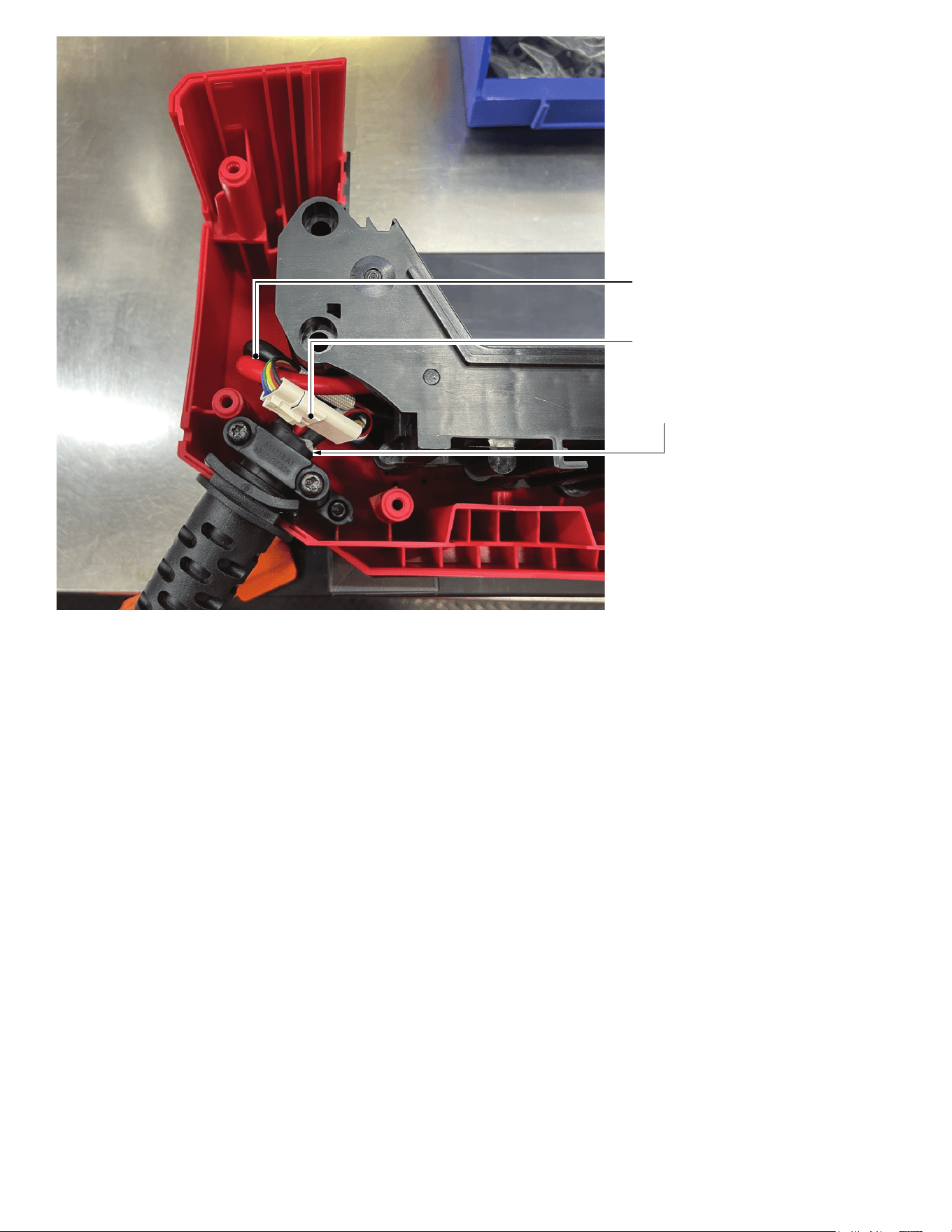
Be sure red and black wires are tucked down in
the housing and away from screw bosses to
prevent pinching.
It is important that the wire connectors are
assembled properly. Make sure that connectors
are seated firmly and squarely together.
Cord jacket to extend .25” minimum beyond
cord clamp.