
2
Table of Contents
1. Introduction ...............................................................................................................................4
1.1 SignalSymbol/WordDenitions ........................................................................................................................4
2. Unboxing .....................................................................................................................................5
2.1 R2 Meta / R3 Meta / R6 Meta / R8 Meta ......................................................................................................5
2.2 R5 Meta / R7 Meta / R11 Meta ............................................................................................................................5
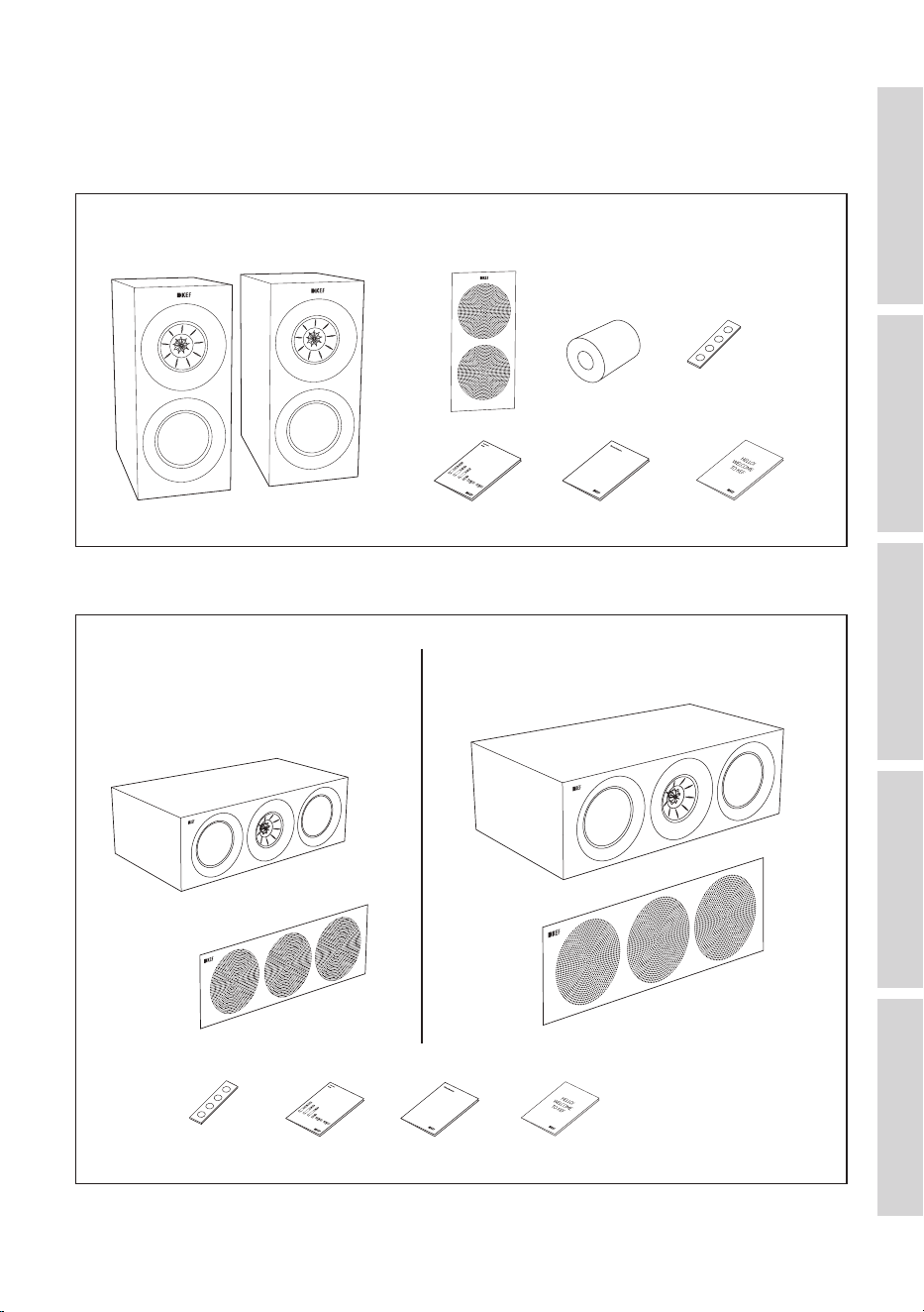
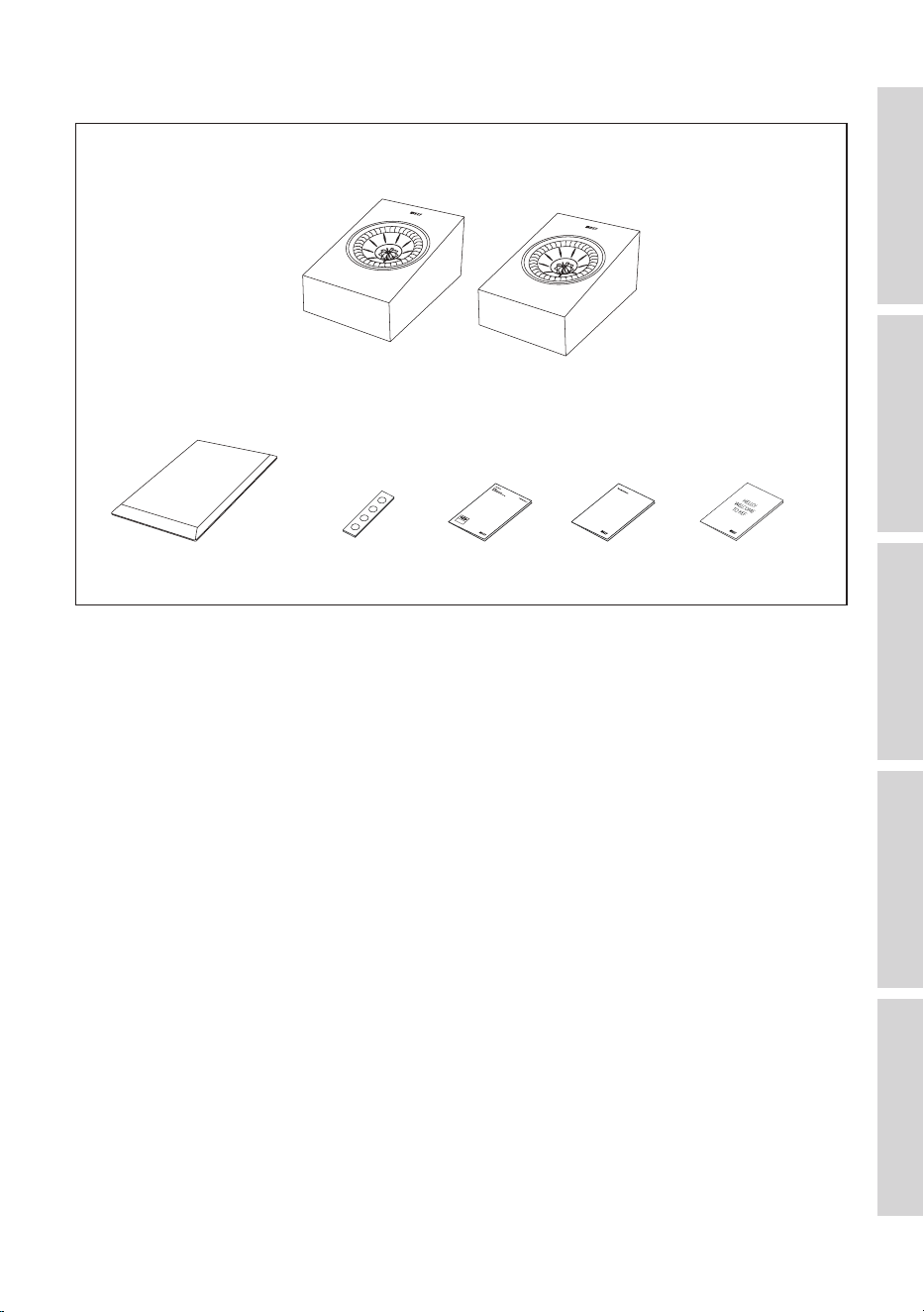
3. In the Box....................................................................................................................................6
3.1 R3 Meta ..............................................................................................................................................................................6
3.2 R2 Meta / R6 Meta ......................................................................................................................................................6
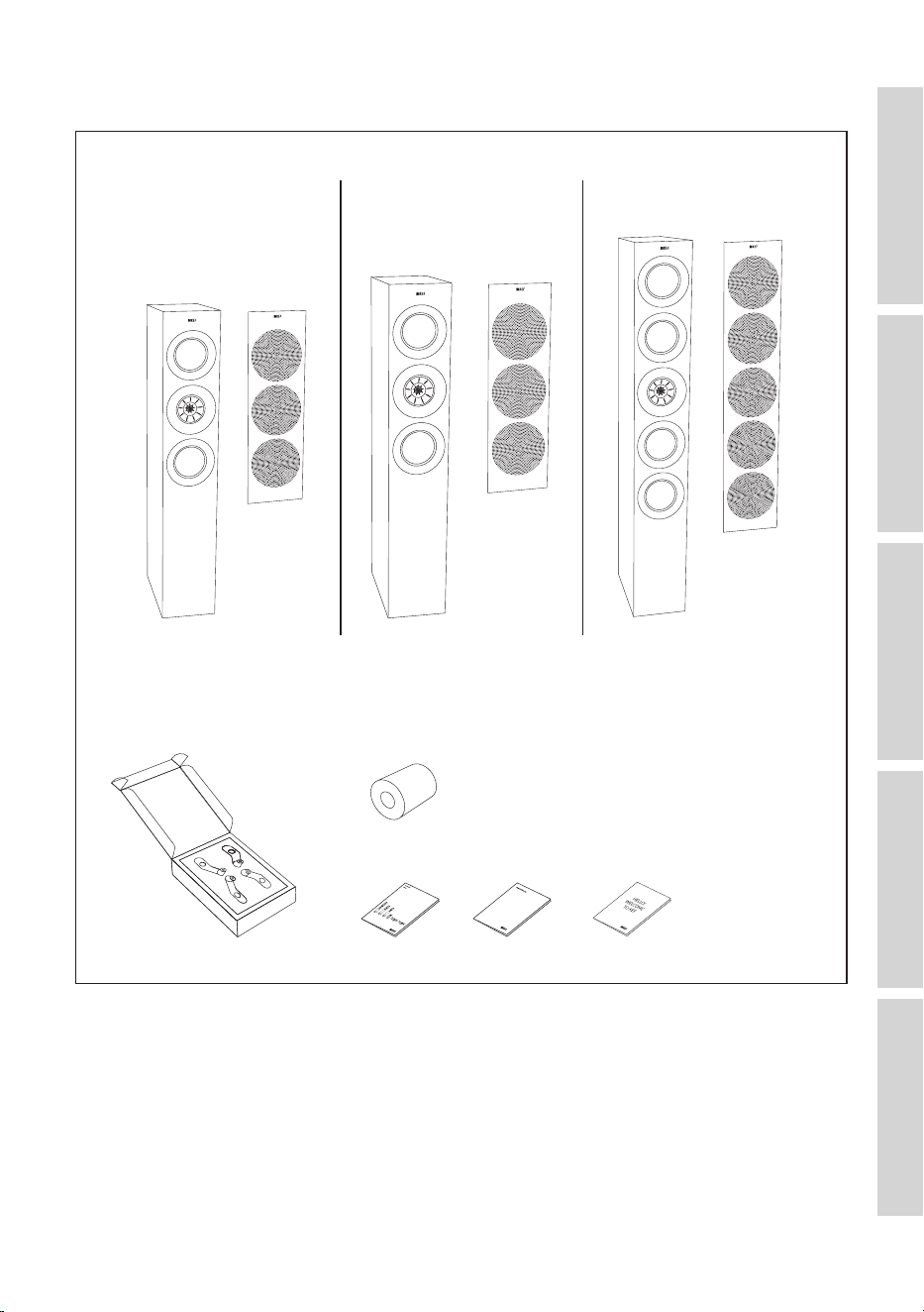
3.3 R5 Meta / R7 Meta / R11 Meta ............................................................................................................................7
3.4 R8 Meta ..............................................................................................................................................................................8
4. Loudspeaker Installation .........................................................................................................9
4.1 Installing the Rubber Feet .......................................................................................................................................9
4.1.1 R3 Meta ......................................................................................................................................................................9
4.1.2 R8 Meta ......................................................................................................................................................................9
4.1.3 R2 Meta / R6 Meta .............................................................................................................................................9
4.2 Installing the Plinths .................................................................................................................................................. 10
4.2.1 R5 Meta / R7 Meta / R11 Meta ................................................................................................................10
4.3 Installing Floorstanding Loudspeakers .......................................................................................................... 11
4.4 Installing Bookshelf Loudspeakers .................................................................................................................. 11
4.5 Installing Centre Loudspeakers ........................................................................................................................12
4.6 Installing R8 Meta on other speakers ........................................................................................................... 12
4.7 Installing R8 Meta on a Wall ............................................................................................................................... 13
5. Loudspeaker Positioning .......................................................................................................15
5.1 Listening Space and Uni-Q Driver Array ...................................................................................................15
5.2 Importance of Positioning Your Loudspeakers.......................................................................................15
5.3 Setting up Your Loudspeakers .......................................................................................................................... 16
5.3.1 Stereo System ..................................................................................................................................................... 16
5.3.1.1 Positioning Stereo System................................................................................................................17
5.3.2 Home Theatre System .................................................................................................................................. 18
5.3.2.1 Positioning a 5.2 or 7.2 System ..................................................................................................... 19
5.3.2.2 Positioning a 5.1.4 System ................................................................................................................. 20
5.3.2.3 Positioning a 7.1.4 System ................................................................................................................. 21
5.4 Positioning in Irregular Rooms ..........................................................................................................................22
5.5 Managing Room Modes ......................................................................................................................................... 24
6. Connections ............................................................................................................................ 25
6.1 Single Wire or Bi-Wire Connections ...........................................................................................................25
6.2 Bi-Amplication ..........................................................................................................................................................26
6.3 Making Connections ..............................................................................................................................................26
6.3.1 R3 Meta / R5 Meta / R7 Meta / R11 Meta .......................................................................................26
6.3.2 R2 Meta / R6 Meta ......................................................................................................................................... 27
6.3.3 R8 Meta .................................................................................................................................................................27
6.4 Cable Gauge and Length ......................................................................................................................................28
7. Fine Tuning ................................................................................................................................29
7.1 Port Bungs ...................................................................................................................................................................... 29
7.2 Using Customised Feet ........................................................................................................................................30

3
8. Running In .................................................................................................................................31
9. Care and Maintenance ...........................................................................................................32
9.1 Cleaning the Loudspeakers .................................................................................................................................32
9.2 UseandStorageofMicrobreGrilles ..........................................................................................................32
9.3 CleaningtheMicrobreGrilles ......................................................................................................................... 32
10. Disposal .....................................................................................................................................33
10.1 Disposing of the Packaging ..................................................................................................................................33
10.2 Disposing of the Loudspeakers.........................................................................................................................33
11. FAQ and Troubleshooting ................................................................................................... 34
11.1 General ............................................................................................................................................................................34
11.2 Floorstanding Loudspeakers ...............................................................................................................................34
11.3 Loudspeakers on Bookshelves or Stands ...................................................................................................34
11.4 LCR (Left/Centre/Right Channel)...................................................................................................................35
11.5 Dolby Atmos Loudspeakers ...............................................................................................................................35
11.6 Care and Maintenance ...........................................................................................................................................35
12. Appendix ...................................................................................................................................37
12.1 Specications ..............................................................................................................................................................37
12.2 Dimensional Drawings ...........................................................................................................................................44
4
Table of ContentsInstallationPositioningConnectionsFAQ and Troubleshooting
1. Introduction
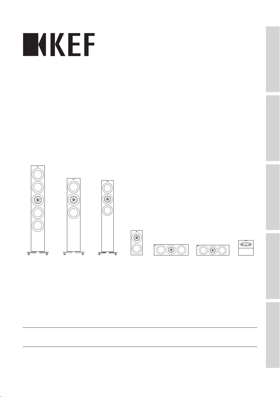
Thank you for choosing KEF R Series Hi-Fi Loudspeakers.
The R series includes seven loudspeaker models, each designed and engineered to
produce sound with exquisite detail and incredible insight.
Blending craftsmanship, innovation, and the award-winning Metamaterial Absorption
Technology (MAT), the R series makes high performance audio more versatile and
accessible than ever – whether in stereo for music or in a home theatre setup.
Please read and follow this user manual carefully before using the loudspeaker systems.
1.1 Signal Symbol/Word Definitions
The following symbols and signal words are used in this user manual.
WARNING!
This signal symbol/word designates a hazard with moderate
risk, which may result in death or severe injury if not avoided.
NOTICE!
This signal word warns of possible damage to property.
This symbol provides you with useful additional information
on handling and use.
5
Table of ContentsInstallationPositioningConnectionsFAQ and Troubleshooting
2. Unboxing
NOTICE!
Risk of damage!
Improper handling of the loudspeakers may result in damage.
• Pay extra attention not to touch or push on the loudspeaker drivers (cones) in the
process.
Follow the instructions below to unbox the loudspeakers.
2.1 R2 Meta / R3 Meta / R6 Meta / R8 Meta
1. Placetheloudspeakercartonboxontheoororonastablesurface.
2. Slice open the sealing tape on the top end. Take out the printed materials and the
port bungs (R3 Meta only).
3. To take out the loudspeaker, you may choose to remove the top protective cap and
take the loudspeaker out of the carton box from the top, or keep the top protective
capintactandipthecartonboxupsidedownonthelongside.
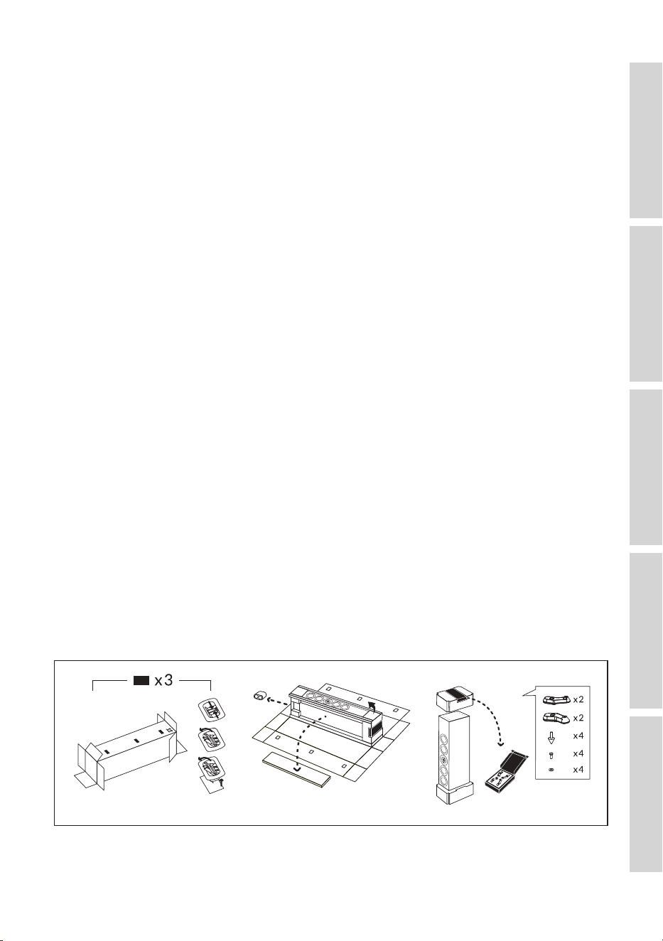
2.2 R5 Meta / R7 Meta / R11 Meta
1. Placetheloudspeakercartonboxhorizontallyatontheoorwiththeplasticclip
side on top. Slice open the sealing tape on both ends of the carton box and remove
the plastic clips on the side.
2. Fully open the carton box to reveal the internal packaging. Take out the loudspeaker
grille box (on the side), the port bungs and the supporting paper corner protectors
on all the long sides.
3. Flip the loudspeaker upside down with the accessory box on top. Take out the
accessory box and check the contents.
9
Table of ContentsInstallationPositioningConnectionsFAQ and Troubleshooting
4. Loudspeaker Installation
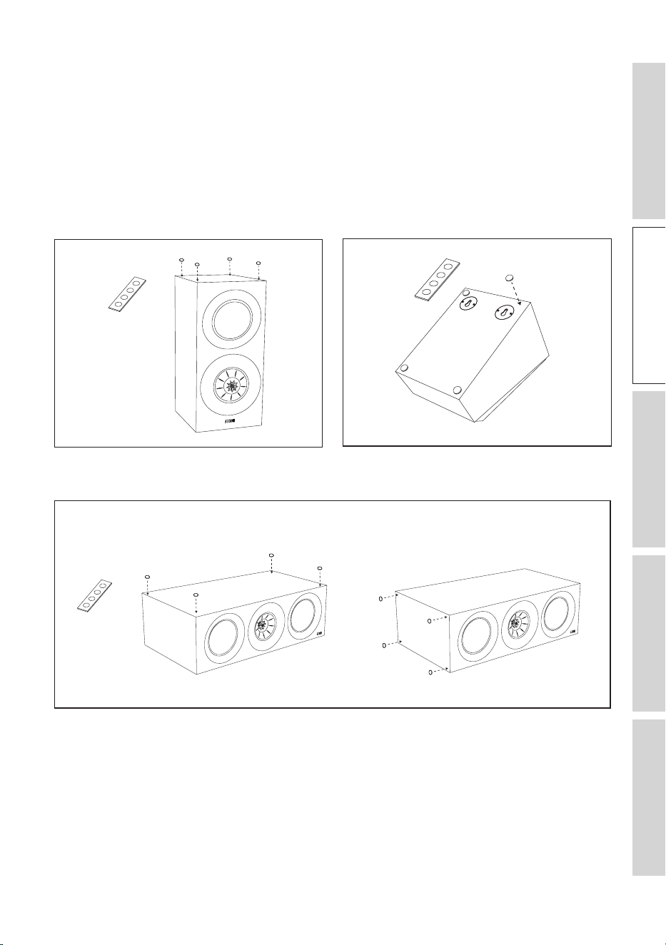
4.1 Installing the Rubber Feet
Putting on the provided rubber feet helps to decouple the loudspeakers from their
contacting surfaces. This helps to isolate any vibrations from transmitting between the
loudspeakers and nearby furniture and objects, avoiding noise or resonances.
4.1.1 R3 Meta 4.1.2 R8 Meta
4.1.3 R2 Meta / R6 Meta
Horizontal placement Vertical placement
10
Table of ContentsInstallationPositioningConnectionsFAQ and Troubleshooting
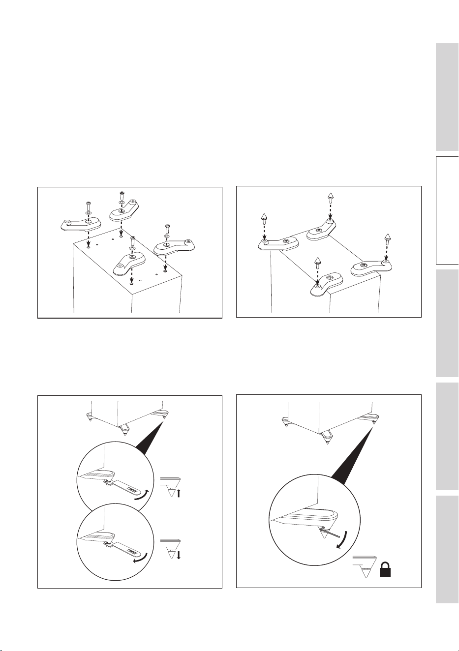
4.2 Installing the Plinths
4.2 .1 R5 Meta / R7 Meta / R11 Meta
These loudspeakers are intended to be floor mounted only. It is important to ensure
that the loudspeakers stand firmly on the floor using the plinths and spike feet supplied
whenever possible for stability.
1. Align the plinths with their attachment holes on the underside of the loudspeaker.
Secure the plinths using the screws and washers supplied.
2. Fit the spikes to the plinths using the spanner tool supplied.
3. Incasetheloudspeakerwobbleswhenplacedontheoor,usethespannertool
suppliedtoadjusttheheightsofthespikesuntiltheyalltouchtheoorandthe
loudspeakerrmlystandsontheoor.
4. Finally, lock the spikes by tightening the grub screws with the hex key supplied.
11
Table of ContentsInstallationPositioningConnectionsFAQ and Troubleshooting
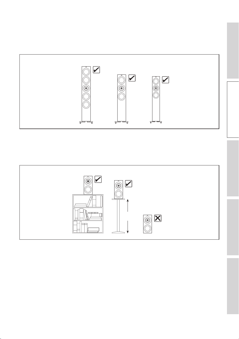
4.3 Installing Floorstanding Loudspeakers
Always use plinths at the bottom of the floorstanding loudspeakers and place the
loudspeakers on solid, stable and level surfaces.
R7 Meta
R11 Meta
R5 Meta
4.4 Installing Bookshelf Loudspeakers
Always place the bookshelf loudspeakers on shelves or stands. Do not place them
directly on the floor.
R3 Meta
R3 Meta
R3 Meta
450-600 mm
(18"–24")
12
Table of ContentsInstallationPositioningConnectionsFAQ and Troubleshooting
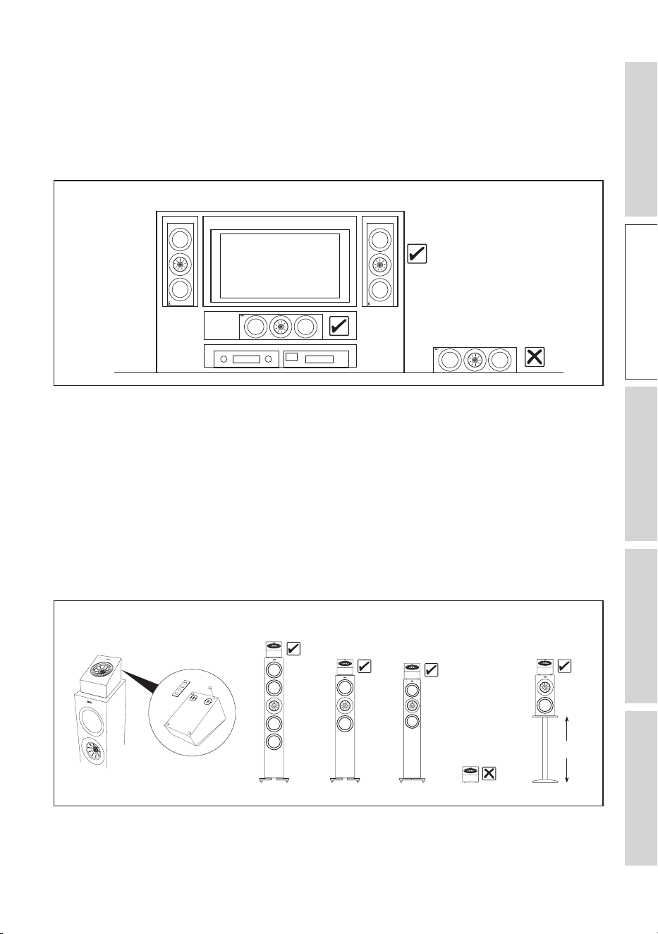
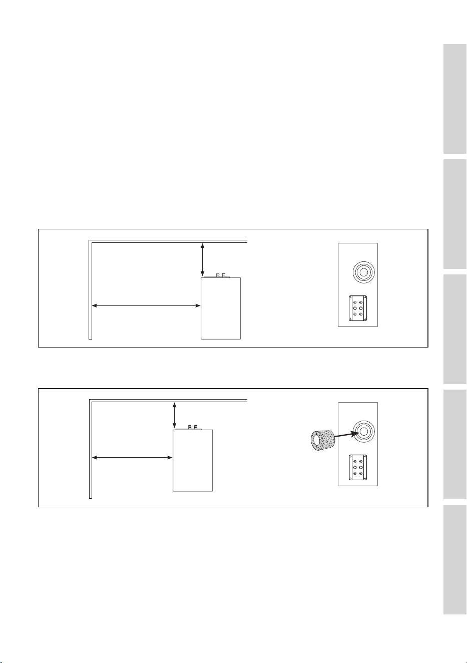
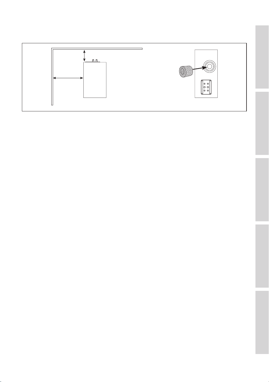
4.5 Installing Centre Loudspeakers
Always align the centre loudspeaker to the centre line of the screen, it can be above
or below the TV, or directly behind a perforated projector screen (check with the
projector screen manufacturer to make sure the screen is acoustically transparent). Do
not place the centre loudspeaker directly on the floor.
R6 Meta / R2 Meta
R6 Meta / R2 Meta
4.6 Installing R8 Meta on other speakers
NOTICE!
Risk of damage!
Improper handling of the loudspeakers may result in damage.
• Always use rubber feet at the bottom of the surround loudspeakers and place them
above floorstanding or bookshelf loudspeakers. Do not place them directly on the
floor.
R8 Meta
R8 Meta
R8 Meta
R8 Meta
450 – 600 mm
(18" – 24")
R8 Meta
R11 Meta R7 Meta R5 Meta
R3 Meta
13
Table of ContentsInstallationPositioningConnectionsFAQ and Troubleshooting
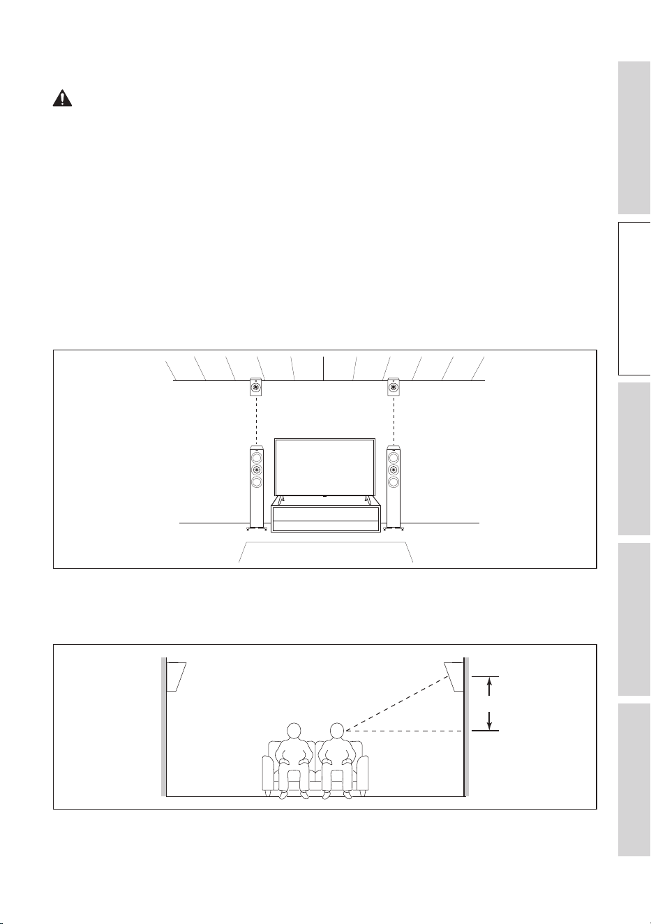
4.7 Installing R8 Meta on a Wall
WARNING!
Risk of injury and damage!
Improper installation may result in injury and damage.
• No attempt should be made to install the loudspeakers on the walls unless you
are sure that you will not be cutting through electric cables, water or gas pipes, or
supporting joists.
Apart from being a Dolby Atmos enabled speaker to be used on top of another
speaker, the R8 Meta can also be used as an on-wall Dolby Atmos speaker and an on-
wall surround speaker.
As an on-wall Dolby Atmos speaker, install the R8 Meta about the same width as your
front/rear speaker, and as close to the wall/ceiling edge as possible.
As an on-wall surround speaker, mount the R8 Meta at the desired location so that the
Uni-Q driver points towards the head level of the listening area and adjust as you see
fit (usually 600 mm or 2 feet above ear level).
~ 600 mm (2 .)
14
Table of ContentsInstallationPositioningConnectionsFAQ and Troubleshooting
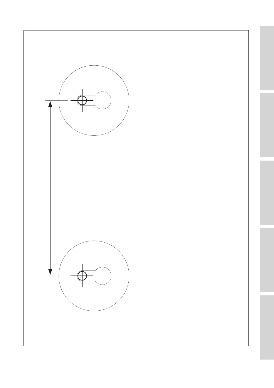
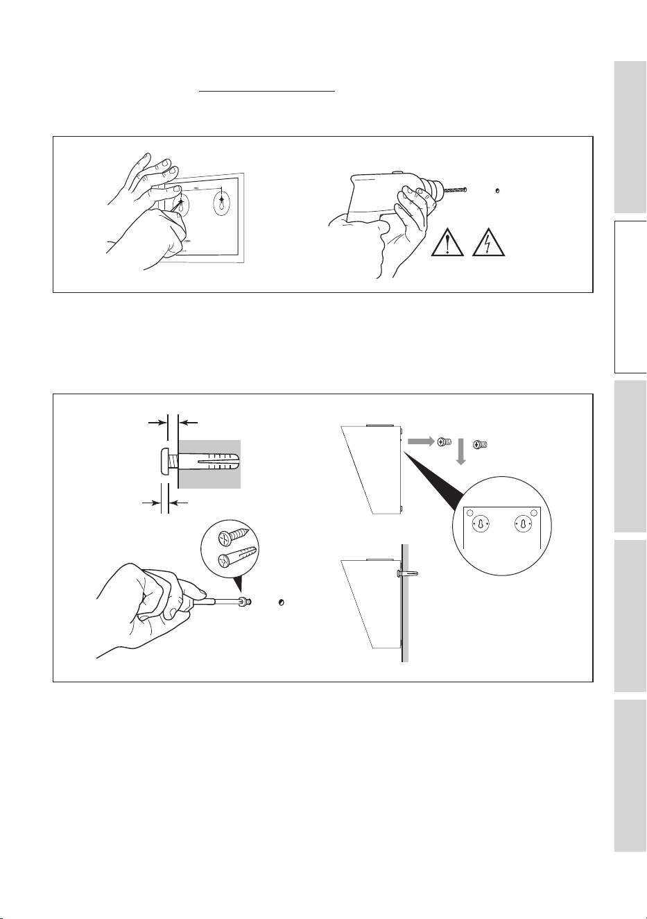
1. Determine the installation location and use the supplied template to mark the drilling
points (see chapter “Dimensional Drawings”).
2. Drill 2 holes on the walls with an electric drill.
~ 600 mm (2 .)
WARNING
3. Insertapairofhollowwallxings(notsupplied)intothedrilledholes,thendrive
2screws(notsupplied)intothexings.Takenoteoftherequiredprotrusionand
clearance.
4. Hang the loudspeaker on the protruding heads of the screws.
Min. 1.5 mm
Max. 5 mm
×2
~ 600 mm (2 .)

15
Table of ContentsInstallationPositioningConnectionsFAQ and Troubleshooting
5. Loudspeaker Positioning
5.1 Listening Space and Uni-Q Driver Array
The KEF R Series loudspeaker systems are all equipped with Uni-Q driver arrays. The
Uni-Q technology is designed to significantly improve loudspeaker placement flexibility
and enhance the listening experience in various listening environments.
With the tweeter placed precisely at the acoustic centre of the bass/midrange cone,
this unique design has several benefits that make it well-suited for different loudspeaker
placements:
• Ensures a more coherent and time-aligned sound dispersion, reducing phase issues
and improving off-axis response. You can enjoy a more consistent sound quality from
various listening positions in the room.
• Creates a wider listening sweet spot where you can experience high-quality sound
even when you are not directly in front of the loudspeaker on-axis.
• Enables versatile placement options without compromising sound quality. You have
greater flexibility to adapt the loudspeaker placement to your room’s layout and
listening preferences.
5.2 Importance of Positioning Your Loudspeakers
Even with the benefits that the Uni-Q driver array bring, loudspeaker positioning in a
room is still of utmost importance when it comes to achieving the best possible audio
performance and listening experience.
Here are the benefits of getting the loudspeakers positioned properly:
• Creates an ideal listening area where the audio quality is at its best in your space.
• Creates a well-defined and immersive soundstage where sounds, voices or
instruments appear to come from a specific location.
• Controls the reflections on the surfaces in a room (e.g. walls, floor and ceiling), leading
to a well-defined imaging and correct tonal balance.
• Minimises room resonances (standing waves which could cause bass cancellations or
emphasis) and enhances the perceived tonal balance of the system.

16
Table of ContentsInstallationPositioningConnectionsFAQ and Troubleshooting
5.3 Setting up Your Loudspeakers
Follow these steps to position your loudspeakers for optimal sound quality:
1. Take note of the room’s dimensions, shape and construction materials. Different
room sizes and shapes will affect the way sound transmits and interacts with surfaces,
impacting the loudspeaker positioning choices.
Large empty spaces with hard surfaces (e.g. windows and mirrors) tend to create
more acoustic issues. If possible, add furniture, curtains, area rugs, and other soft
furnishings to help diffuse and absorb sound.
2. Identify where you will be sitting most of the time when listening to music or
watching movies.
• If possible, avoid a primary listening position in close proximity to any of the walls.
• If your room is rectangular, it is most ideal to setup up your TV and loudspeakers
against one of the short walls and have the loudspeakers face the longer
dimension of the room.
These guidelines are for reference only. Remember that your listening space and
preferences are unique. Feel free to experiment to find out the setup that you enjoy
the most.
5.3.1 Stereo System
• In a stereo system, place the two front loudspeakers at an equal distance from the
mid point of the primary listening area, so that they form an quasi-equilateral triangle.
This helps to ensure the best stereo imaging.
• Ideally the loudspeakers should be 1.5 m to 3 m apart. The distance should be wider
or at least the same as the width of the listening area.
• Symmetry is very important for optimal stereo. Try to keep the loudspeakers and the
listening area symmetrical with respect to the room layout. Ideally the side walls, to
the left and the right of the loudspeakers, should be at the same distance and of the
same construction.
• Ideally a wall (also known as the “front wall”) should be directly behind the front
loudspeakers. Both loudspeakers should be the same distance from this wall. The
distance between the loudspeakers and the “front wall” is usually the most sensitive
parameter for low frequency tuning. Experiment with different distances to find the
best compromise between bass response and overall sound, ideally it should not be
less than 225 mm (9”) but in cases where this cannot be met, it is advised to tune
with port bungs (see chapter Port bungs).
• It is advised to keep at least 0.5 m (20") distance between the speaker and the side
wall.
17
Table of ContentsInstallationPositioningConnectionsFAQ and Troubleshooting
• With Uni-Q technology, the KEF R series loudspeakers have a wider listening sweet
spot and can work well without toeing-in. However, it is always a good idea to
experiment to fine-tune the stereo image to your preferences by trying different toe-
in angle.
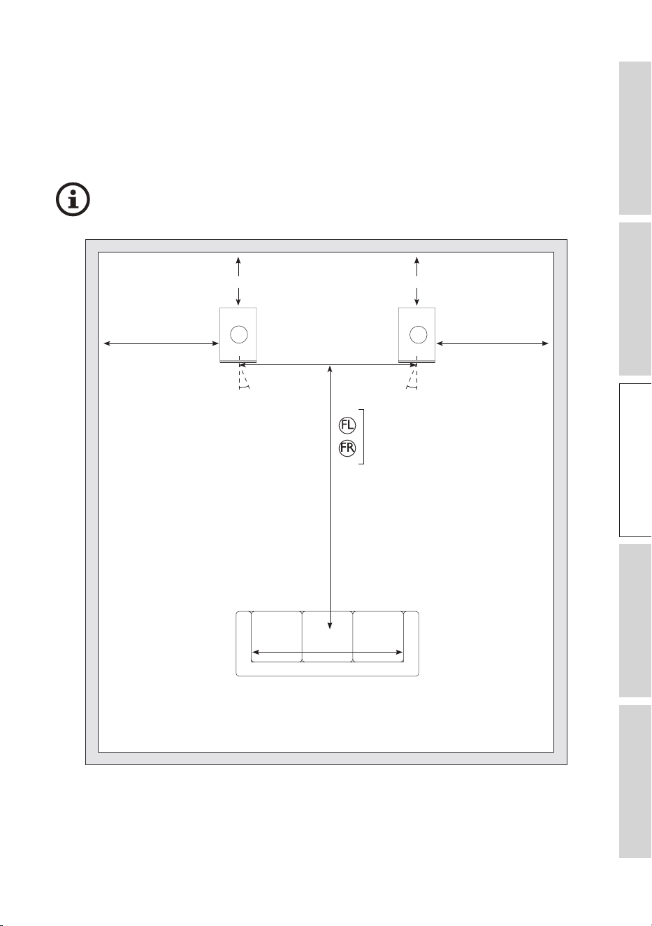
5.3.1.1 Positioning Stereo System
Take note of the recommended distances when positioning the loudspeakers.
225 mm (9") MIN.
W: 1.5 – 3 m (5 f t. – 10 f t.)
D: 0.8 – 1.2 x W
0.5 m (20") MIN.
225 mm (9") MIN.
0 - 15° 0 - 15°
0.5 m (20") MIN.
FL
FR
R3 Meta
R5 Meta
R7 Meta
R11 Meta
W: ≥A
A
Channel abbreviations:
FL = Front left, FR = Front right

18
Table of ContentsInstallationPositioningConnectionsFAQ and Troubleshooting
5.3.2 Home Theatre System
• If you have a home theater setup, always position the centre channel loudspeaker to
line up with the centre line of the screen horizontally and as close to the screen as
possible. It can be above or below the TV, or directly behind a perforated projector
screen (check with the projector screen manufacturer to make sure the screen is
acoustically transparent). It should be directed towards the primary listening area.
Getting the centre channel loudspeaker setup right is the key to how your home
theatre system will sound.
• For the front left and right main loudspeakers, the guidelines in 5.3.1 Stereo System
still applies, but it is advised to place them close to the side edges of the screen to
keep the sound image in scale with the visual image.
• If you have a subwoofer, its placement is more flexible, as bass frequencies are
omnidirectional. Experiment with different positions to find the spot where the bass
response is the most even and natural. Common locations are corners or along a
wall. Nevertheless, avoid placing the subwoofer too close to adjacent walls.
• For the surround loudspeakers, position them on the sides or slightly behind the
primary listening area, as shown in following diagrams.
19
Table of ContentsInstallationPositioningConnectionsFAQ and Troubleshooting
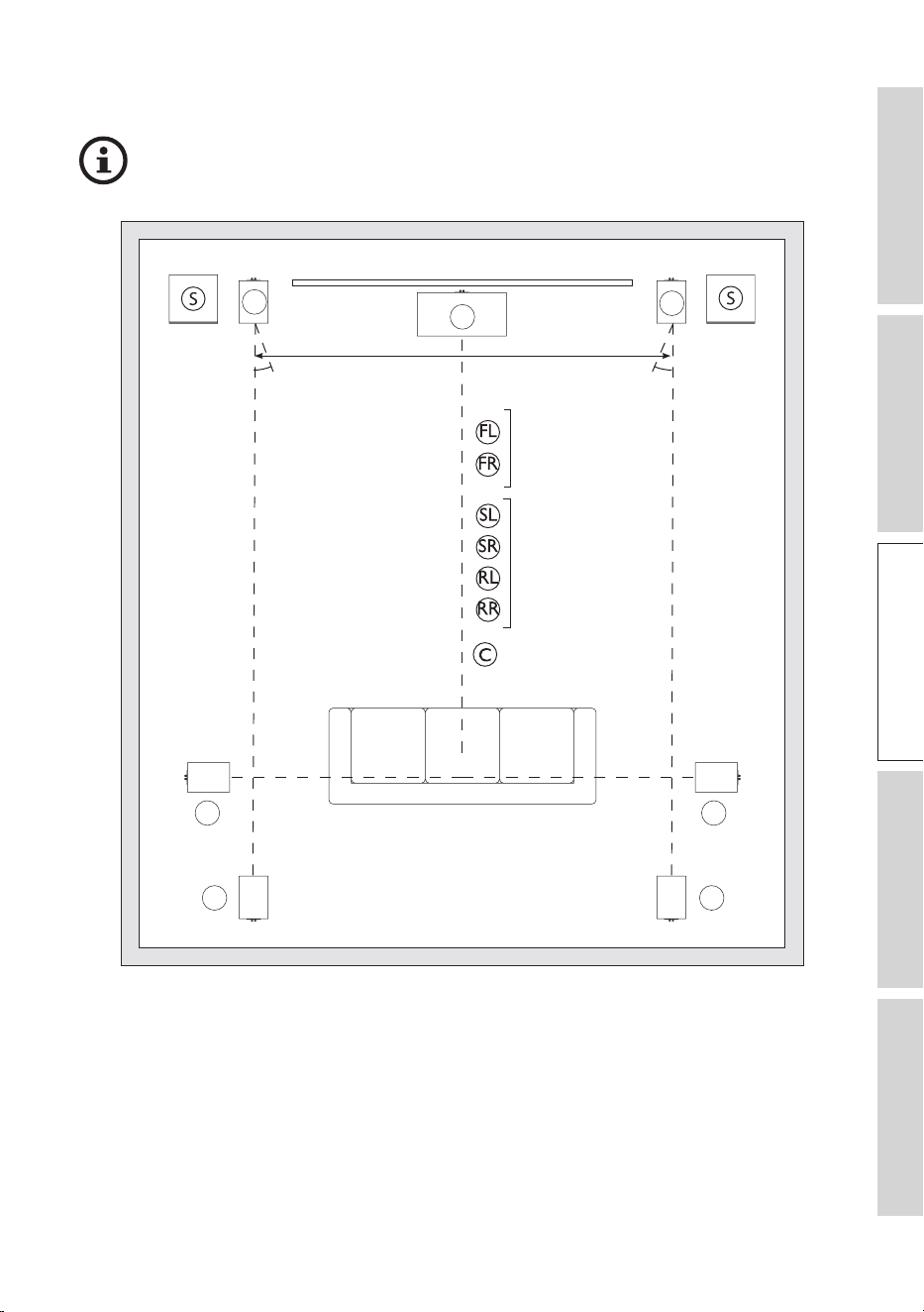
5.3.2.1 Positioning a 5.2 or 7.2 System
Take note of the recommended distances when positioning the loudspeakers.
C
FL
FR
RL RR
SL SR
0 – 15° 0 – 15°
R3 Meta
R5 Meta
R7 Meta
R11 Meta
R3 Meta
R5 Meta
R7 Meta
R11 Meta
R2 Meta
R6 Meta
Channel abbreviations:
FL = Front left, FR = Front right, SL = Surround left, SR = Surround right, RL = Rear left, RR = Rear right,
C = Centre, S = Optional KEF subwoofer
20
Table of ContentsInstallationPositioningConnectionsFAQ and Troubleshooting
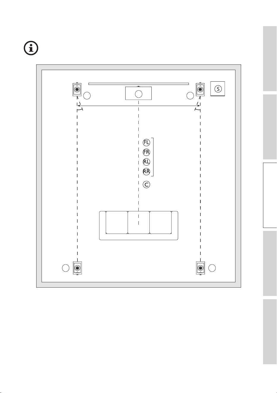
5.3.2.2 Positioning a 5.1.4 System
Take note of the recommended distances when positioning the loudspeakers.
C
FRFL
RL RR
0 – 15° 0 – 15°
R3 Meta + R8 Meta
R5 Meta + R8 Meta
R7 Meta + R8 Meta
R11 Meta + R8 Meta
R2 Meta
R6 Meta
Channel abbreviations:
FL = Front left, FR = Front right, RL = Rear left, RR = Rear right, C = Centre, S = Optional KEF subwoofer
21
Table of ContentsInstallationPositioningConnectionsFAQ and Troubleshooting
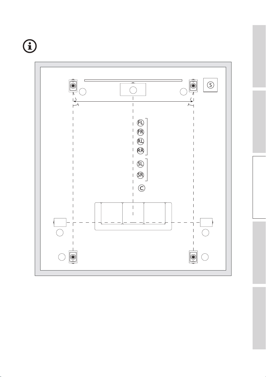
5.3.2.3 Positioning a 7.1.4 System
Take note of the recommended distances when positioning the loudspeakers.
C
FR
FL
RRRL
SL SR
0 – 15° 0 – 15°
R3 Meta + R8 Meta
R5 Meta + R8 Meta
R7 Meta + R8 Meta
R11 Meta + R8 Meta
R3 Meta
R5 Meta
R7 Meta
R11 Meta
R2 Meta
R6 Meta
Channel abbreviations:
FL = Front left, FR = Front right, RL = Rear left, RR = Rear right, SL = Surround left, SR = Surround right,
C = Centre, S = Optional KEF subwoofer

22
Table of ContentsInstallationPositioningConnectionsFAQ and Troubleshooting
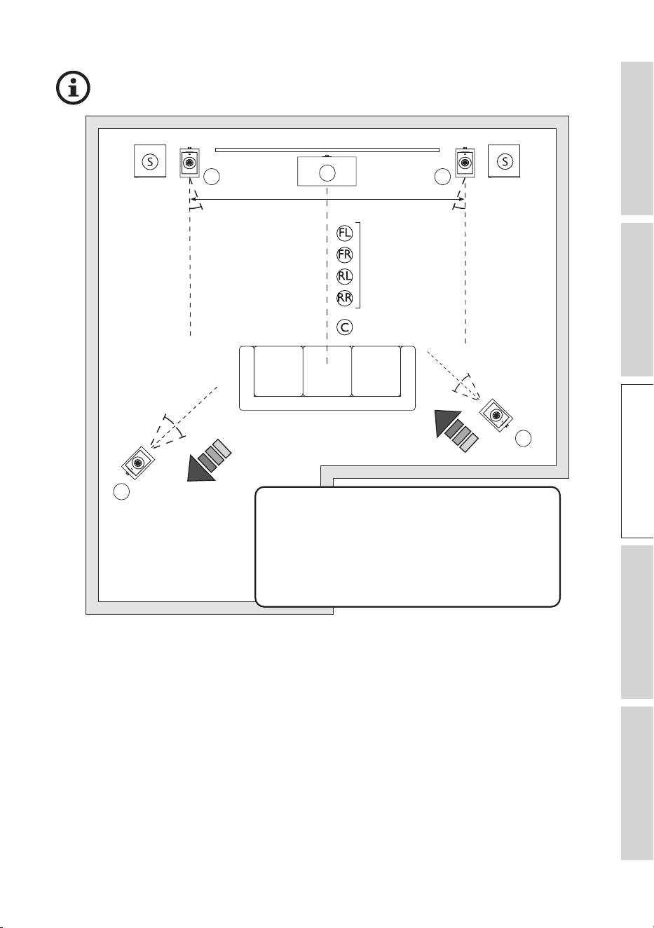
5.4 Positioning in Irregular Rooms
• Try to maintain a consistent acoustic environment surrounding each speaker. In the
example below, try to move the rear left speaker closer to the left wall and the rear
right speaker further away from the lower right corner. This can help compensate the
imbalance in sound due to space difference around the speakers.
• If the speakers are placed at difference distances to the listening position, it is
recommended to compensate for the distance difference in the AV processor settings
for the best result. In below example, as the rear left speaker is placed further away
from listening position than the rear right speaker, the rear left speaker signal delay
should be reduced and amplitude should be increased to avoid sound from skewing
towards one direction.
• Fine-tune the loudspeaker placements by listening to familiar music or movie scenes.
Make small adjustments to the position and angle of the loudspeakers to optimise the
sound.
23
Table of ContentsInstallationPositioningConnectionsFAQ and Troubleshooting
Take note of the recommended distances when positioning the loudspeakers.
C
FRFL
RL
RR
0 – 15° 0 – 15°
R3 Meta + R8 Meta
R5 Meta + R8 Meta
R7 Meta + R8 Meta
R11 Meta + R8 Meta
R2 Meta
R6 Meta
0 – 15°
0 – 15°
0 – 15°
0 – 15°
In this example, try to move the rear left
speaker closer to the left wall and the rear
right speaker further away from the lower
right corner. This can help compensate the
imbalance in sound due to space difference
around the speakers.
Channel abbreviations:
FL = Front left, FR = Front right, RL = Rear left, RR = Rear right, C = Centre, S = Optional KEF subwoofer

24
Table of ContentsInstallationPositioningConnectionsFAQ and Troubleshooting
5.5 Managing Room Modes
Room modes are a phenomenon that occur in enclosed spaces caused by soundwaves
reflecting off of the various surfaces in a room interfering with each other. These sound
waves can constructively or destructively interfere with each other, resulting in room
positions with strong peaks or dips in the frequency response. When positioning your
loudspeakers, room modes can significantly impact the sound quality and perceived
tonal balance in the listening area. Room modes are usually most noticeable in the
low-frequency range (< 300 Hz), impacting the bass response of the loudspeakers and
leading to an uneven and inaccurate representation of the audio.
To address room modes when positioning your loudspeakers, several techniques can
be used:
• If using a subwoofer, experiment with different subwoofer positions to find the spot
where the bass response is the most even.
• Use bass traps in corners or along wall-ceiling and wall-floor junctions to reduce
room modes.
• Strategically place diffusion panels (often made of materials with irregular surfaces) to
break up sound waves and avoid overly dead-sounding spaces.
25
Table of ContentsInstallationPositioningConnectionsFAQ and Troubleshooting
6. Connections
NOTICE!
Risk of damage!
Improper handling of the loudspeakers may result in damage.
• Switch off all audio equipment before connecting the loudspeakers.
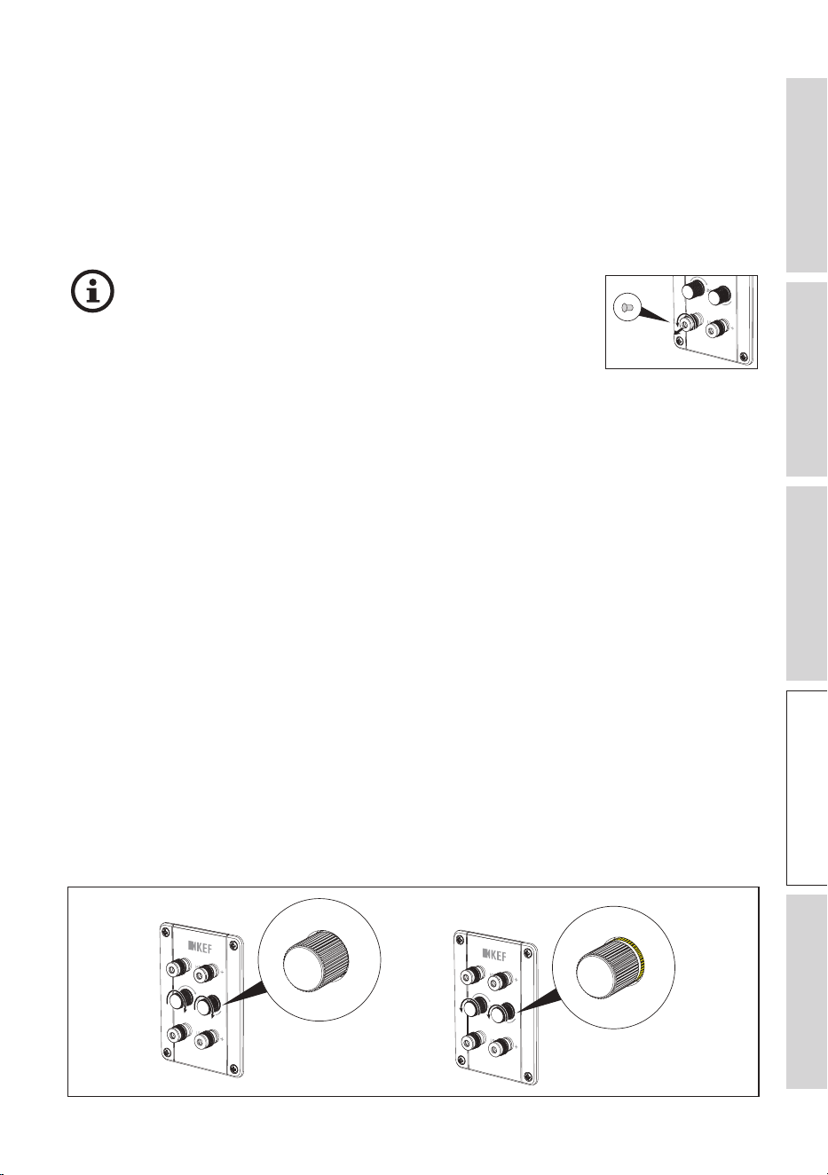
If you want to connect the loudspeakers with banana
plugs, make sure that the plastic caps at the binding posts
of the connectors are removed before doing so. You can
remove the plastic caps by fully unscrewing the metal caps
on the connectors.
6.1 Single Wire or Bi-Wire Connections
You can connect the loudspeakers to your amplifier with single wire or bi-wire
connections.
In a single wire connection, a standard loudspeaker cable with two conductors is used
to connect the amplifier to the loudspeaker.
Bi-wire connections use two separate loudspeaker cables for each loudspeaker. These
cables typically have a pair of connectors at the amplifier end and are divided into
two separate pairs at the loudspeaker end. At the loudspeaker end, one pair of the
cables connects to the loudspeaker’s high-frequency (HF) terminals, and the other pair
connects to the low-frequency (LF) terminals.
For the KEF R Series loudspeakers, you can use one of the connection methods:
• To enable single wire connections, rotate the Link connection knobs clockwise until
the knob is fully tightened and the yellow rings at the base of the knobs cannot be
seen.
• To enable bi-wire connections, rotate the Link connection knobs anticlockwise (or
counterclockwise) until the yellow rings at the base of the knobs fully reveal.
26
Table of ContentsInstallationPositioningConnectionsFAQ and Troubleshooting
6.2 Bi-Amplification
NOTICE!
Risk of damage!
Improper handling of the loudspeakers may result in damage.
• Follow the bi-wire connection steps to make sure the Link connections are
disengaged. Otherwise, it could cause damage to your equipment.
Bi-amplification (bi-amping) is possible for the KEF R Series loudspeakers. It is a
loudspeaker setup method using two separate amplifiers or amplifier channels to
power different drivers within a loudspeaker.
6.3 Making Connections
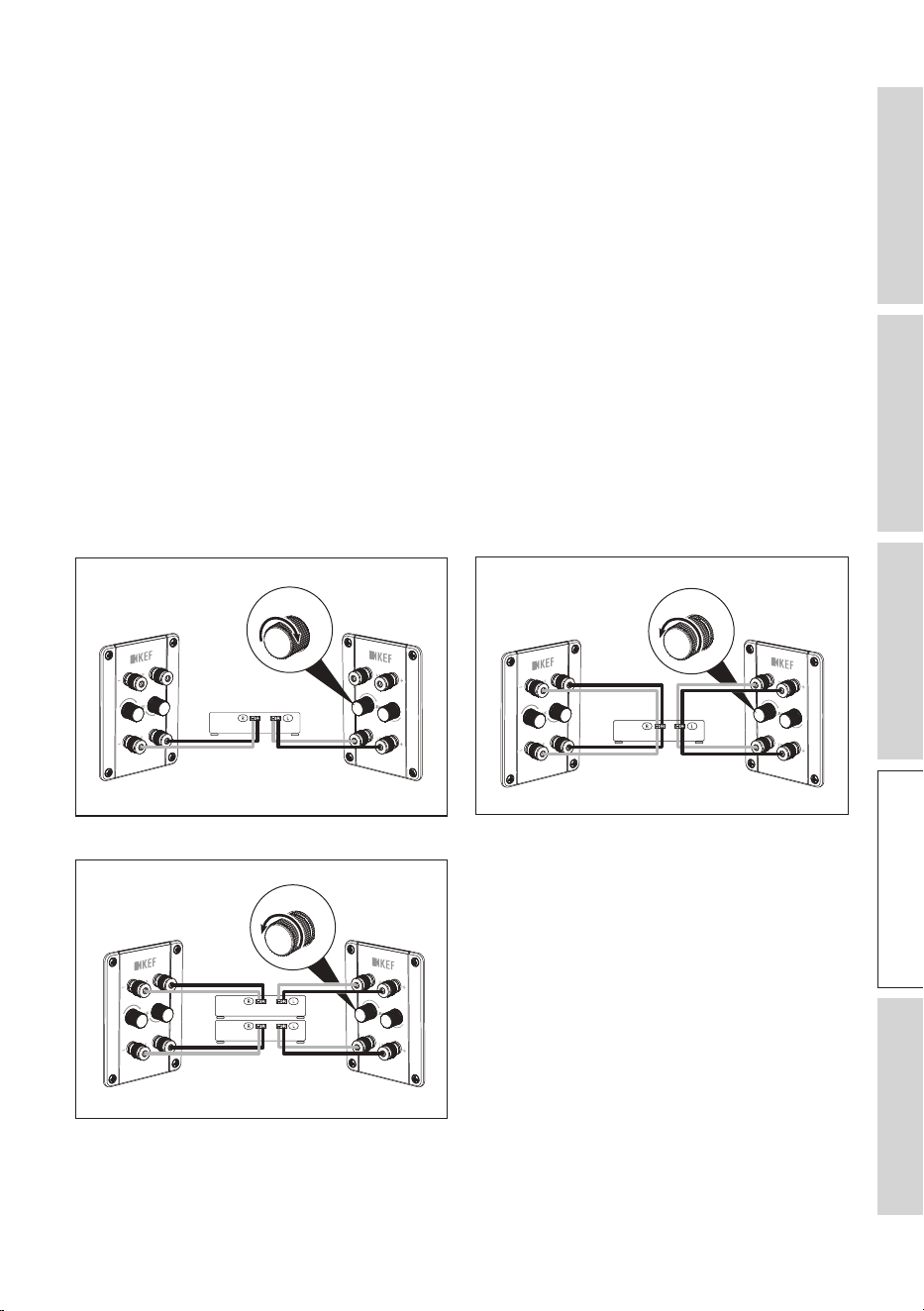
6.3.1 R3 Meta / R5 Meta / R7 Meta / R11 Meta
Single wire connections Bi-wire connections
R
L
AMP
R
L
AMP
Bi-amplified connections
R
L
AMP
Abbreviations: R = Right, L = Left, AMP = Amplifier
27
Table of ContentsInstallationPositioningConnectionsFAQ and Troubleshooting
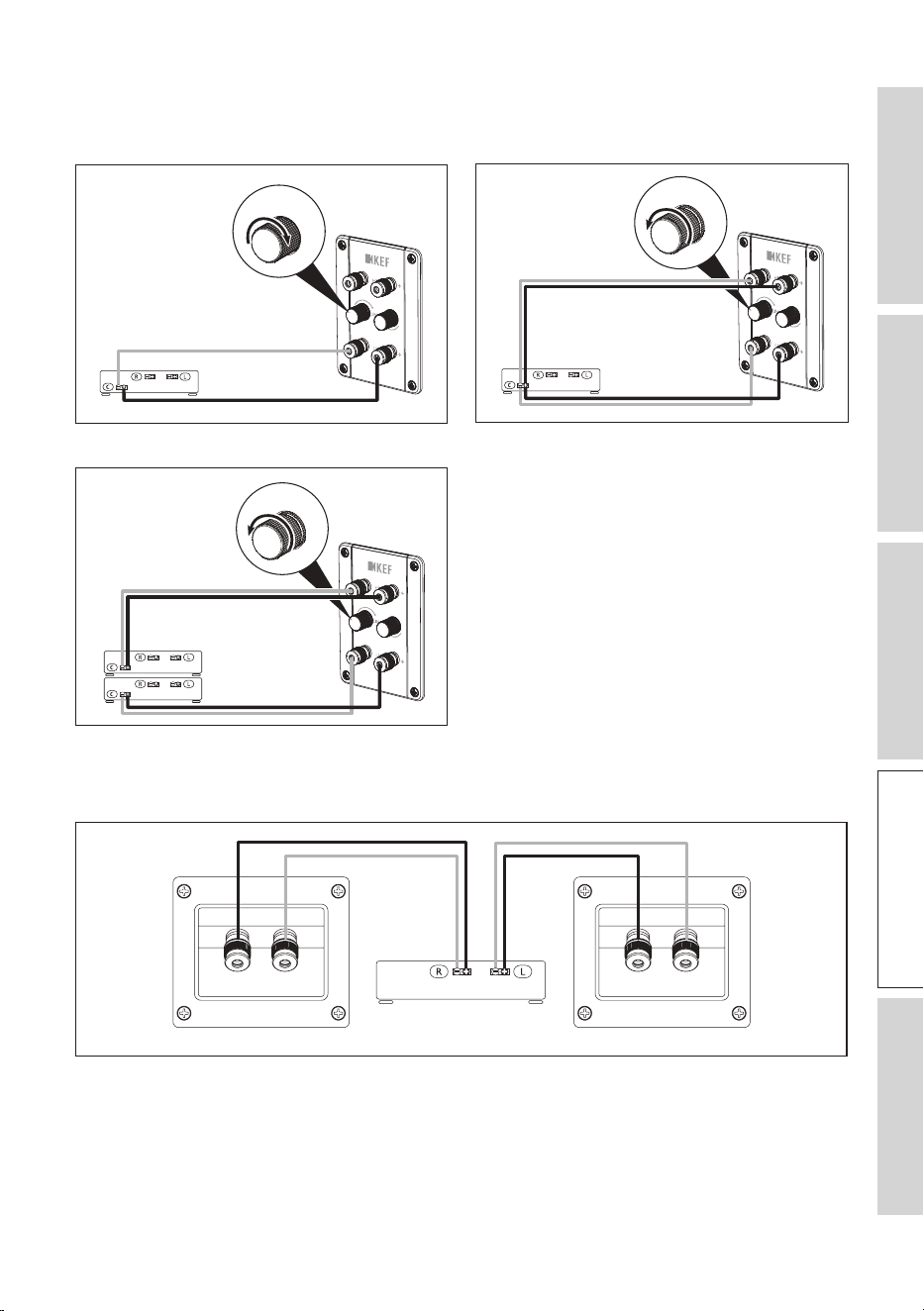
6.3.2 R2 Meta / R6 Meta
Single wire connections Bi-wire connections
C
AMP
C
AMP
Bi-amplified connections
C
AMP
Abbreviations: C = Centre, AMP = Amplifier
6.3.3 R8 Meta
AMP*R L
Abbreviations: R = Right, L = Left, AMP = Amplifier
*Dolby Atmos supported amplifiers
28
Table of ContentsInstallationPositioningConnectionsFAQ and Troubleshooting
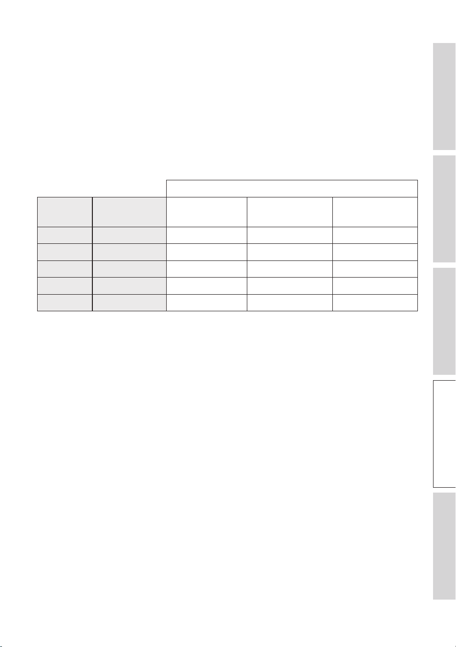
6.4 Cable Gauge and Length
The relationship between cable gauge* and length in a loudspeaker setup is an
important consideration to ensure optimal audio performance and minimize signal loss.
The rule of thumb is: the thicker the cable (smaller AWG) the better. The longer the
distance between the amplifier and the loudspeaker, the thicker the cable is required
for good performance.
Refer to the table below for recommendations on cable lengths in relation to the
loudspeaker’s nominal impedances and cable gauges. The R Series loudspeakers have a
nominal impedance of 4 ohms.
Nominal impedance of loudspeakers
U.S. cable
standard
Cable cross-
section (mm²)
4 ohms 6 ohms 8 ohms
18 AWG 0.823 4.9 m / 16 ft 7.3 m / 24 ft 9.8 m / 32 ft
16 AWG 1.31 7.3 m / 24 ft 11.0 m / 36 ft 14.6 m / 48 ft
14 AWG 2.08 12.2 m / 40 ft 18.3 m / 60 ft 24.4 m / 80 ft
12 AWG 3.31 18.3 m / 60 ft 27.4 m / 90 ft 36.6 m / 120 ft
10 AWG 5.26 30.5 m / 100 ft 45.7 m / 150 ft 61.0 m / 200 ft
*Cable gauge refers to the thickness or diameter of the wire used in the loudspeaker cables. It is typically
measured in American Wire Gauge (AWG) or millimeters squared (mm²).
29
Table of ContentsInstallationPositioningConnectionsFAQ and Troubleshooting
7. Fine Tuning
Remember that fine-tuning involves experimentation. Listen to your loudspeakers
at different positions and volume levels to assess the impact of each adjustment. Be
patient and give yourself time to make adjustments based on what sounds best to you.
7.1 Port Bungs
Use the supplied port bungs to customise the loudspeaker’s bass characteristics to
better suit your listening environment or preferences.
You may consider using port bungs if the loudspeakers are too close to a wall.
• In general, port bungs are not required if the distances to the walls are greater than
the specifications in the diagram below.
> 500 mm
> 1,000 mm
• The use of the outer rings of the port bungs is recommended if the distances to the
walls are within the ranges in the diagram below.
200 – 500mm
500 – 1,000 mm
30
Table of ContentsInstallationPositioningConnectionsFAQ and Troubleshooting
• The use of both outer rings and centre cores of the port bungs is recommended if
the distances to the walls are smaller than the specifications in the diagram below.
< 200 mm
< 500 mm
For models with more than one port, you may experiment with different combinations
of port bungs.
Once the port bungs are inserted, play various types of music or audio content and
listen to the changes in the bass response to find out which you prefer.
7.2 Using Customised Feet
Customised feet with the below specifications would fit the plinths of the R series
loudspeakers.
• M8 Pitch 1.25 18 mm (R5 Meta, R7 Meta, R11 Meta)
• M8 Pitch 1.25 15 mm (R3 Meta)

31
Table of ContentsInstallationPositioningConnectionsFAQ and Troubleshooting
8. Running In
Running in (also known as loudspeaker break-in or burn-in) is the process of
conditioning new loudspeakers to reach their optimal performance level.
When loudspeakers are manufactured, their components are relatively stiff and rigid.
Running in the loudspeakers involves playing audio through them for a certain period
of time to allow these components to loosen up and settle into their normal operating
state (e.g. greater flexibility in the loudspeaker suspensions).
Some tips for running in loudspeakers:
• Start playing music at moderate volumes and gradually increase the volume level over
time.
• Play a variety of music genres and audio contents during the running-in process to
ensure that all frequency ranges are adequately exercised.
• Be patient and allow enough time for running-in to take its course. The duration
varies depending on the loudspeaker design and materials used. However, it
generally ranges from a few hours to several days of continuous play.

32
Table of ContentsInstallationPositioningConnectionsFAQ and Troubleshooting
9. Care and Maintenance
NOTICE!
Risk of damage!
Improper handling of the loudspeakers may result in damage.
• Make sure that no water or other liquids penetrate the housing of the loudspeakers.
• Never immerse the loudspeakers in water or other liquids.
• Do not use any aggressive cleaners, brushes with metal or nylon bristles, or sharp
or metallic utensils such as knives, hard scrapers and the like. They could damage
the surface.
9.1 Cleaning the Loudspeakers
1. Clean the surfaces of the loudspeakers with a clean lint-free cloth. If necessary, use an
alcohol-free cleaner (e.g. screen cleaner, eyeglass lens cleaner) to remove stubborn
stains.
2. To clean the Uni-Q drivers (loudspeaker cones), use an anti-static cleaner and a soft
sponge. Be careful as the drivers may be damaged if too much force is used.
9.2 Use and Storage of Microfibre Grilles
• Do not twist, bend or drop the grilles.
• Do not expose the grilles to direct sunlight.
• When not in use, store the grilles flat or in their original packaging.
9.3 Cleaning the Microfibre Grilles
• To remove dirt, wipe the grille surfaces with a dry, soft brush in a single direction.
• To remove stains:
1. Only use a damp, lint-free cloth or natural sponge to dab and wipe the stain.
Avoid rubbing to prevent spreading or tracking the stain deeper.
Do not use any stain remover or cleaning agent.
If you use a sponge, rinse it in clean water and wring well between each wipe.
2. Let the grille air dry, do not apply heat.

33
Table of ContentsInstallationPositioningConnectionsFAQ and Troubleshooting
10. Disposal
10.1 Disposing of the Packaging
Sort the packaging before you dispose of it. Dispose of paperboard, cardboard and
wrappings in accordance with your local guidelines.
10.2 Disposing of the Loudspeakers
Old appliances may not be disposed of in the household waste!
The loudspeakers are electronic products and may not be able to be disposed of
as household waste. Please dispose of your loudspeakers in accordance with the
regulations in force in your city or county. This ensures that old appliances are recycled
in a professional manner and reduces negative consequences.

34
Table of ContentsInstallationPositioningConnectionsFAQ and Troubleshooting
11. FAQ and Troubleshooting
11.1 General
1. How to locate the serial numbers of the loudspeakers?
• The serial number can be found on the packaging box near one of the barcode labels
on the side of the packaging box. Alternatively, it can also be found on the rear panel
(where the speaker terminals are located) of the loudspeaker.
2. What type of loudspeaker cable is recommended?
• Consider loudspeaker cables made from high-quality oxygen-free copper or high
purity copper conductors. They are designed to minimise oxidation and ensure better
conductivity.
• Also consider loudspeaker cables with high quality insulation. They can reduce signal
interference and ensure accurate signal transmission.
3. What is the recommended diameter of the loudspeaker cables?
• In general, the longer the run is from your amplifier to the loudspeakers, the lower
the cable gauge is. See chapter “Cable Gauge and Length”.
11.2 Floorstanding Loudspeakers
1. Can I use the loudspeakers without the plinths (traverse legs)?
• Using plinths is highly recommended. The plinths provide a more stable foundation
which helps prevent the loudspeakers from tipping over.
2. What is the thread size of the spikes and the screws for the plinths?
• M8 (1.25 mm pitch)
3. Can I use other spikes instead of those that come with the loudspeakers?
• You can use third party spikes with the same specifications.
4. How far apart are the screw holes at the bottom of the plinths?
• Refer to the Dimensional Drawings.
11.3 Loudspeakers on Bookshelves or Stands
1. What is the size of the screws for mounting the R3 Meta on the S3 stand?
• M8 (1.25 mm pitch)
2. How deep are the screw holes at the bottom of the loudspeakers?
• 18 mm
35
Table of ContentsInstallationPositioningConnectionsFAQ and Troubleshooting
3. How far apart are the screw holes at the bottom of the loudspeakers?
• Refer to the Dimensional Drawings.
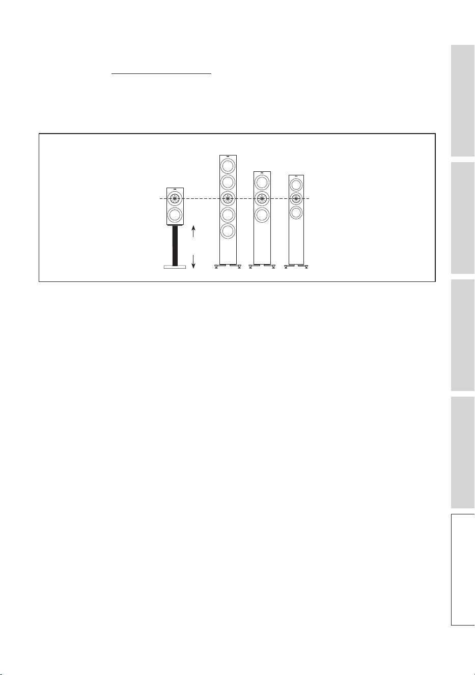
4. What should be the height of the stand for R3 Meta so that the Uni-Q driver
aligns with the other floorstanding speakers?
• Use a stand of 497 mm (19.5").
R3 Meta
497 mm
(19.5")
11.4 LCR (Left/Centre/Right Channel)
1. Are decoupling feet recommended?
• Install the supplied rubber feet to reduce vibrations and isolate the loudspeakers from
the room and other objects.
2. Do I need to place the centre loudspeaker in an upward position?
• With the wide dispersion of the Uni-Q driver array, tilting of the centre loudspeaker
to align with the ear level is in general not necessary. However, it is always a good
practice to experiment with the placement and position of the loudspeaker to get
the best possible audio performance.
11.5 Dolby Atmos Loudspeakers
1. What is the angle of the top/front bae?
• The angle of the top/front baffle is 110 degrees.
11.6 Care and Maintenance
1. How should I clean the loudspeakers?
1. Clean the surfaces of the loudspeakers with a clean lint-free cloth. If necessary, use an
alcohol-free cleaner (e.g. screen cleaner, eyeglass lens cleaner) to remove stubborn
stains.

36
Table of ContentsInstallationPositioningConnectionsFAQ and Troubleshooting
2. To clean the Uni-Q drivers (loudspeaker cones), use an anti-static cleaner and a soft
sponge. Be careful as the drivers may be damaged if too much force is used.
2. What type of cleaning cloth is recommened for cleaning?
• Microfibre cloths are recommended.
3. How to remove scratches on the painted surfaces?
• If the scratches are superficial (only affecting the coat layer), a commerically available
scratch removal product may help.
• Car wax may also help to fill in minor scratches and improve the overall appearance
of the painted surface.
• If the scratches are deep and extensive, consider seeking professional help.
4. What kind of paint is applied on the loudspeakers?
• Polyester paint or acrylic paint is used.
5. How to remove wax on the loudspeakers?
• Allow the wax to cool and then use a plastic or wooden spatula to gently scrape off
any excess wax from the surface.
• If there is still some residual wax, use a hair dryer on low heat to soften it and then
wipe it with a paper towel or cloth.
6. What type of solvent is recommended to remove oil/fat from the painted surfaces?
• Always use a gentle solvent that will not damage the paint or cause discoloration.
Some recommendations are mild dish soap solution, rubbing alcohol and any
commercial degreaser.
37
Table of ContentsInstallationPositioningConnectionsFAQ and Troubleshooting
12. Appendix
12.1 Specifications
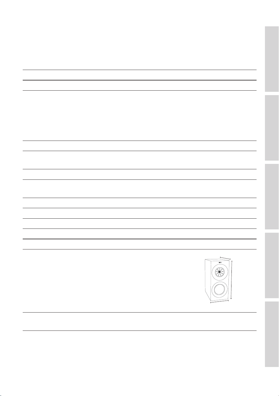
R3 Meta
Model R3 Meta
Design Three-way bass reflex
Drive units Uni-Q Driver Array:
HF: 25 mm (1 in.) vented aluminium dome
with MAT
MF: 125 mm (5 in.) aluminium cone
Bass Unit:
LF: 165 mm (6.5 in.) hybrid aluminium cone
Crossover frequency 420 Hz, 2.3 kHz
Frequency range (-6 dB)
Typical in-room bass response (-6 dB)
38 Hz – 50 kHz
30 Hz
Frequency response (±3 dB) 58 Hz – 28 kHz
Harmonic distortion (90 dB, 1 m) < 1 % 73 Hz and above
< 0.5 % 90 Hz – 20 kHz
Maximum output 110 d B
Amplifier power (recommended) 15 – 180 W
Nominal impedance 4Ω(min.3.2Ω)
Sensitivity (2.83 V / 1 m) 87 dB
Weight* 12.4 kg (27.3 lbs)
Dimensions (H x W x D) with
terminals*
422 × 200 × 336 mm
(16.6 × 7.9 × 13.2 in.)
422 mm
336 mm
200 mm
Finishes Black Gloss / White Gloss / Walnut / Indigo
Gloss Special Edition
*Measurement per unit
38
Table of ContentsInstallationPositioningConnectionsFAQ and Troubleshooting
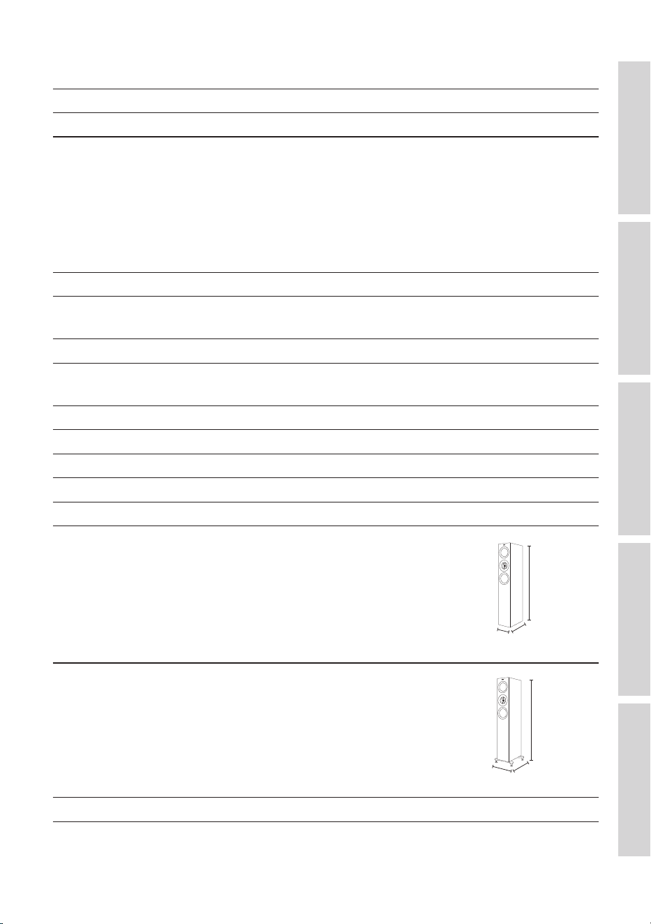
R5 Meta
Model R5 Meta
Design Three-way bass reflex
Drive units Uni-Q Driver Array:
HF: 25 mm (1 in.) vented aluminium dome
with MAT
MF: 125 mm (5 in.) aluminium cone
Bass Unit:
LF: 2 × 130 mm (5.25 in.) hybrid aluminium
cone
Crossover frequency 400 Hz, 2.7 kHz
Frequency range (-6 dB)
Typical in-room bass response (-6 dB)
38 Hz – 50 kHz
29 Hz
Frequency response (±3 dB) 52 Hz – 28 kHz
Harmonic distortion (90 dB, 1 m) < 1 % 75 Hz and above
< 0.5 % 110 Hz – 20 kHz
Maximum output 110 d B
Amplifier power (recommended) 15 – 200 W
Nominal impedance 4Ω(min.3.2Ω)
Sensitivity (2.83 V / 1 m) 87 dB
Weight* 24.5 kg (54.0 lbs)
Dimensions (H x W x D) with
terminals*
1,025 × 175 × 344 mm
(40.4 × 6.9 × 13.5 in.)
1,025 mm
344 mm
175 mm
Dimensions (H x W x D) with
terminals and plinths*
1,072 × 272 × 344 mm
(42.2 × 10.7 × 13.5 in.)
1,072 mm
344 mm
272 mm
Finishes Black Gloss / White Gloss / Walnut
*Measurement per unit
39
Table of ContentsInstallationPositioningConnectionsFAQ and Troubleshooting
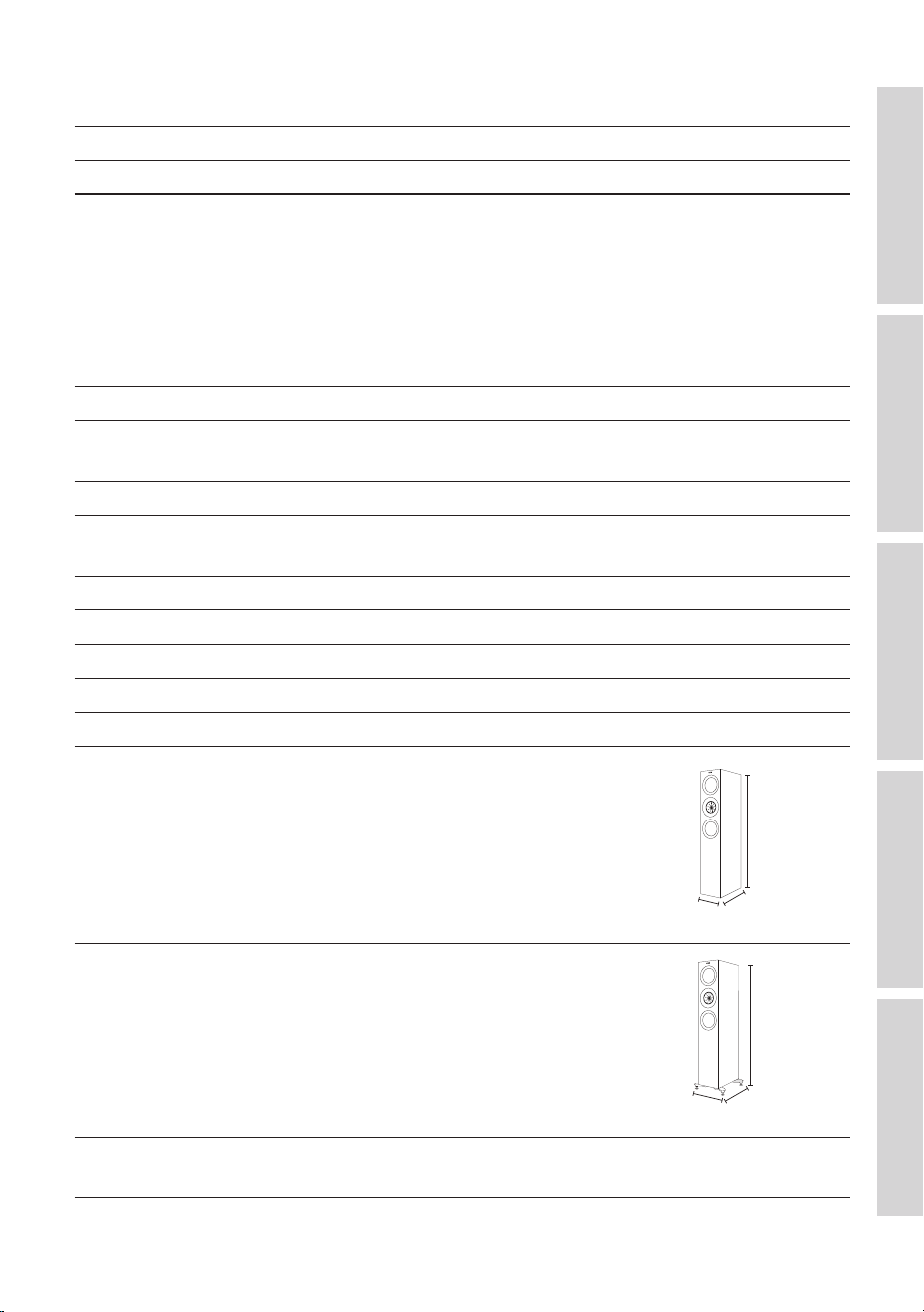
R7 Meta
Model R7 Meta
Design Three-way bass reflex
Drive units Uni-Q Driver Array:
HF: 25 mm (1 in.) vented aluminium dome
with MAT
MF: 125 mm (5 in.) aluminium cone
Bass Unit:
LF: 2 × 165 mm (6.5 in.) hybrid aluminium
cone
Crossover frequency 400 Hz, 2.4 kHz
Frequency range (-6 dB)
Typical in-room bass response (-6 dB)
33 Hz – 50 kHz
27 Hz
Frequency response (±3 dB) 48 Hz – 28 kHz
Harmonic distortion (90 dB, 1 m) < 1 % 76 Hz and above
< 0.5 % 110 Hz – 20 kHz
Maximum output 111 d B
Amplifier power (recommended) 15 – 250 W
Nominal impedance 4Ω(min.3.2Ω)
Sensitivity (2.83 V / 1 m) 88 dB
Weight* 29.3 kg (64.6 lbs)
Dimensions (H x W x D) with
terminals*
1,062 × 200 × 384 mm
(41.8 × 7.9 × 15.1 in.)
1,062 mm
384 mm
200 mm
Dimensions (H x W x D) with
terminals and plinths*
1,109 × 311 × 384 mm
(43.7 × 12.2 × 15.1 in.)
1,109 mm
384 mm
311 m m
Finishes Black Gloss / White Gloss / Walnut / Titanium
Gloss Special Edition
*Measurement per unit
40
Table of ContentsInstallationPositioningConnectionsFAQ and Troubleshooting
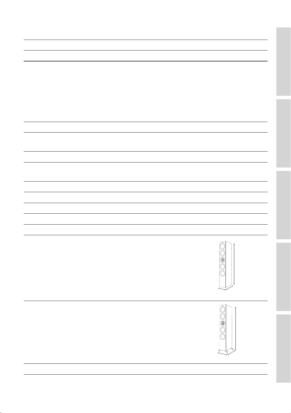
R11 Meta
Model R11 M e t a
Design Three-way bass reflex
Drive units Uni-Q Driver Array:
HF: 25 mm (1 in.) vented aluminium dome
with MAT
MF: 125 mm (5 in.) aluminium cone
Bass Unit:
LF: 4 × 165 mm (6.5 in.) hybrid aluminium
cone
Crossover frequency 330 Hz, 2.5 kHz
Frequency range (-6 dB)
Typical in-room bass response (-6 dB)
30 Hz – 50 kHz
26 Hz
Frequency response (±3 dB) 46 Hz – 28 kHz
Harmonic distortion (90 dB, 1 m) < 1 % 33 Hz and above
< 0.5 % 80 Hz – 20 kHz
Maximum output 113 d B
Amplifier power (recommended) 15 – 300 W
Nominal impedance 4Ω(min.3.2Ω)
Sensitivity (2.83 V / 1 m) 90 dB
Weight* 36.5 kg (80.5 lbs)
Dimensions (H x W x D) with
terminals*
1,249 × 200 × 384 mm
(49.2 × 7.9 × 15.1 in.)
1,249 mm
384 mm
200 mm
Dimensions (H x W x D) with
terminals and plinths*
1,296 × 311 × 384 mm
(51.0 × 12.2 × 15.1 in.)
1,296 mm
384 mm
311 m m
Finishes Black Gloss / White Gloss / Walnut
*Measurement per unit
41
Table of ContentsInstallationPositioningConnectionsFAQ and Troubleshooting
R2 Meta
Model R2 Meta
Design Three-way closed box
Drive units Uni-Q Driver Array:
HF: 25 mm (1 in.) vented aluminium dome
with MAT
MF: 125 mm (5 in.) aluminium cone
Bass Unit:
LF: 2 × 130 mm (5.25 in.) hybrid aluminium
cone
Crossover frequency 560 Hz, 2.5 kHz
Frequency range (-6 dB)
Typical in-room bass response (-6 dB)
58 Hz – 50 kHz
43 Hz
Frequency response (±3 dB) 67 Hz – 28 kHz
Harmonic distortion (90 dB, 1 m) < 1 % 84 Hz and above
< 0.5 % 95 Hz – 20 kHz
Maximum output 110 d B
Amplifier power (recommended) 15 – 200 W
Nominal impedance 4Ω(min.3.2Ω)
Sensitivity (2.83 V / 1 m) 87 dB
Weight* 15.4 kg (34.0 lbs)
Dimensions (H x W x D) with
terminals*
175 × 550 × 309 mm
(6.9 × 21.7 × 12.2 in.)
309 mm
175 mm
550 mm
Finishes Black Gloss / White Gloss / Walnut
*Measurement per unit
42
Table of ContentsInstallationPositioningConnectionsFAQ and Troubleshooting
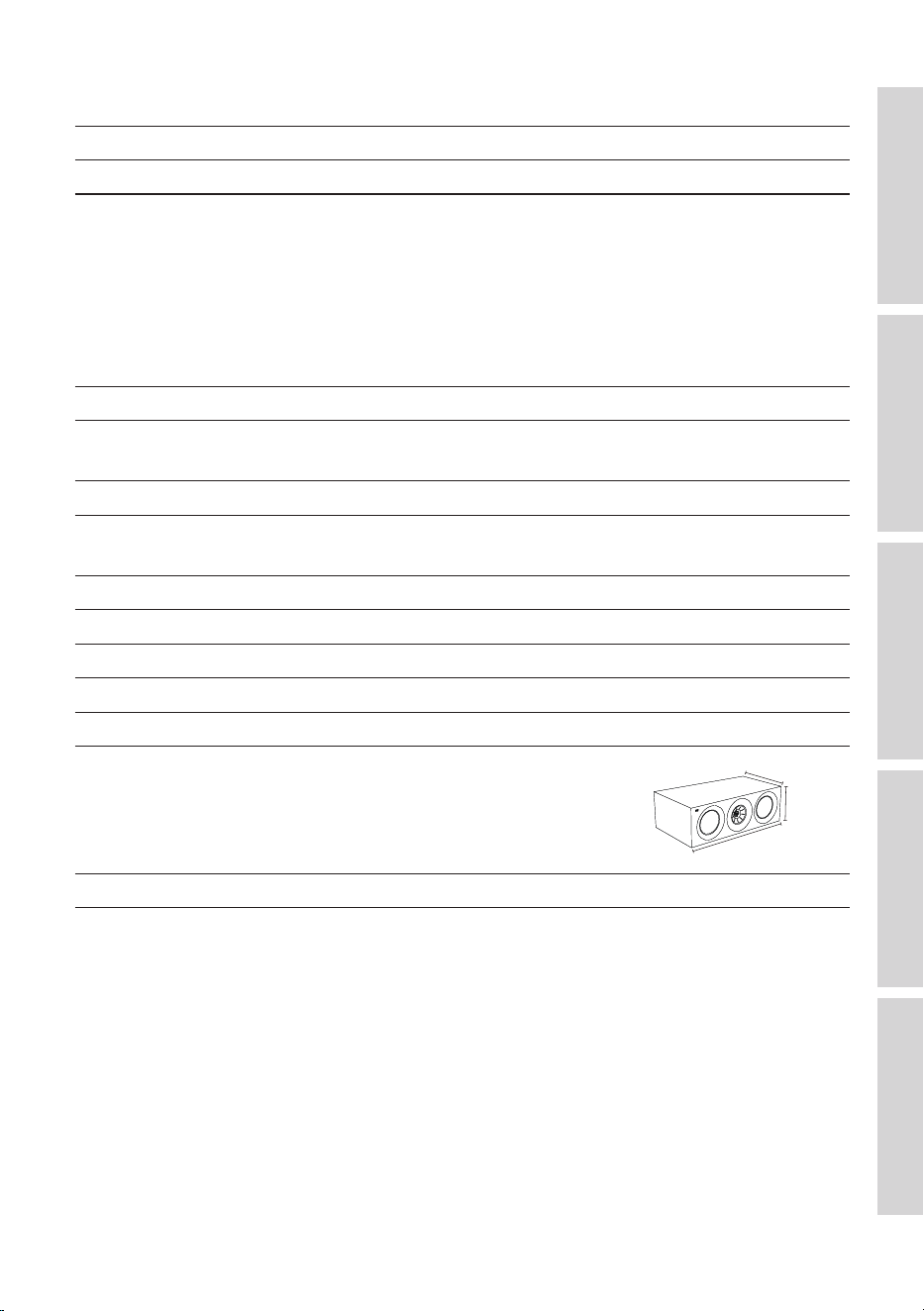
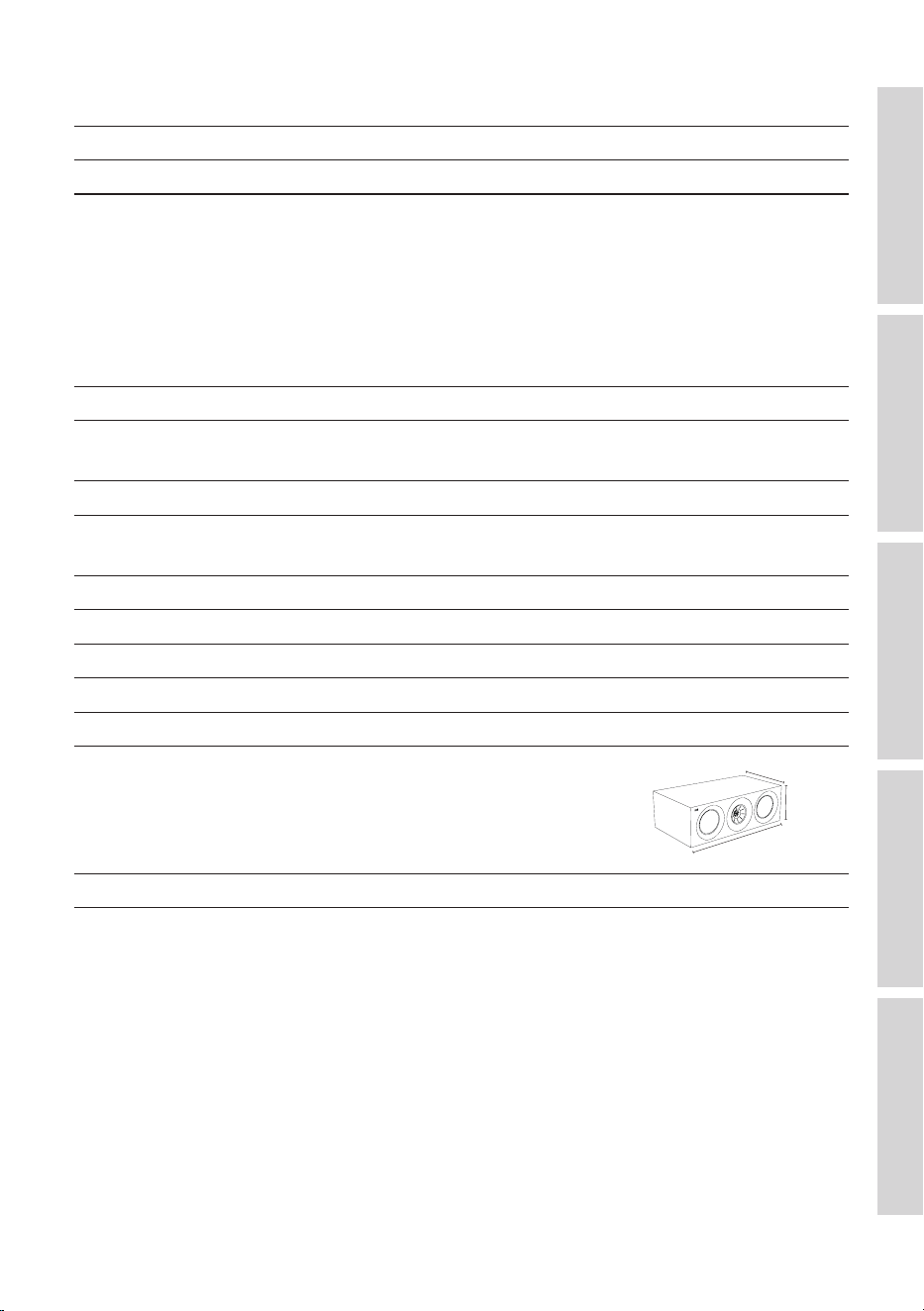
R6 Meta
Model R6 Meta
Design Three-way closed box
Drive units Uni-Q Driver Array:
HF: 25 mm (1 in.) vented aluminium dome
with MAT
MF: 125 mm (5 in.) aluminium cone
Bass Unit:
LF: 2 × 165 mm (6.5 in.) hybrid aluminium
cone
Crossover frequency 550 Hz, 2.4 kHz
Frequency range (-6 dB)
Typical in-room bass response (-6 dB)
55 Hz – 50 kHz
40 Hz
Frequency response (±3 dB) 65 Hz – 28 kHz
Harmonic distortion (90 dB, 1 m) < 1 % 65 Hz and above
< 0.5 % 93 Hz – 20 kHz
Maximum output 111 d B
Amplifier power (recommended) 15 – 250 W
Nominal impedance 4Ω(min.3.2Ω)
Sensitivity (2.83 V / 1 m) 88 dB
Weight* 17.8 kg (39.2 lbs)
Dimensions (H x W x D) with
terminals*
200 × 625 × 339 mm
(7.9 × 24.6 × 13.3 in.)
339 mm
200 mm
625 mm
Finishes Black Gloss / White Gloss / Walnut
*Measurement per unit
43
Table of ContentsInstallationPositioningConnectionsFAQ and Troubleshooting
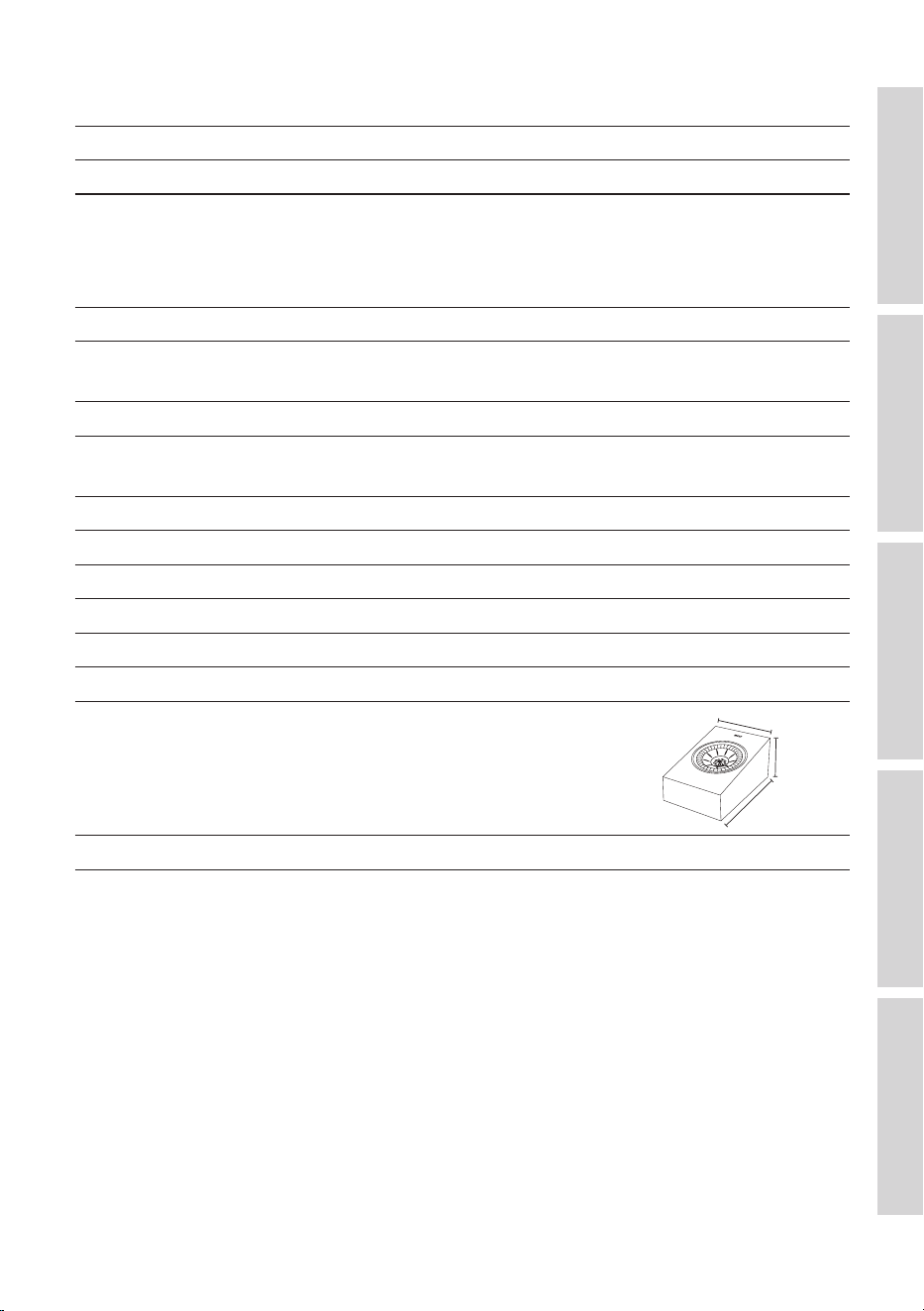
R8 Meta
Model R8 Meta
Design Two-way closed box
Drive units Uni-Q Driver Array:
HF: 25 mm (1 in.) vented aluminium dome
with MAT
MF / LF: 130 mm (5.25 in.) aluminium cone
Crossover frequency 2.6 kHz
Frequency range (-6 dB)
Typical in-room bass response (-6 dB)
88 Hz – 19.5 kHz
–
Frequency response (±3 dB) 97 Hz – 17.5 kHz
Harmonic distortion (90 dB, 1 m) < 1 % 220 Hz and above
< 0.5 % 320 Hz – 20 kHz
Maximum output 106 dB
Amplifier power (recommended) 25 – 150 W
Nominal impedance 4Ω(min.3.2Ω)
Sensitivity (2.83 V / 1 m) 85 dB
Baffle angle 110 °
Weight* 4.5 kg (9.9 lbs)
Dimensions (H x W x D) with
terminals*
174 × 175 × 259 mm
(6.9 × 6.9 × 10.2 in.)
175 mm
174 mm
259 mm
Finishes Black Gloss / White Gloss / Walnut
*Measurement per unit
Metamaterial Absorption Technology is a joint development with Acoustic
Metamaterials Group.
Dolby, Dolby Atmos, and the double-D symbol are registered trademarks of Dolby
Laboratories Licensing Corporation.
KEF reserves the right, in line with continuing research and development, to amend or
change specifications. E&OE.
44
Table of ContentsInstallationPositioningConnectionsFAQ and Troubleshooting
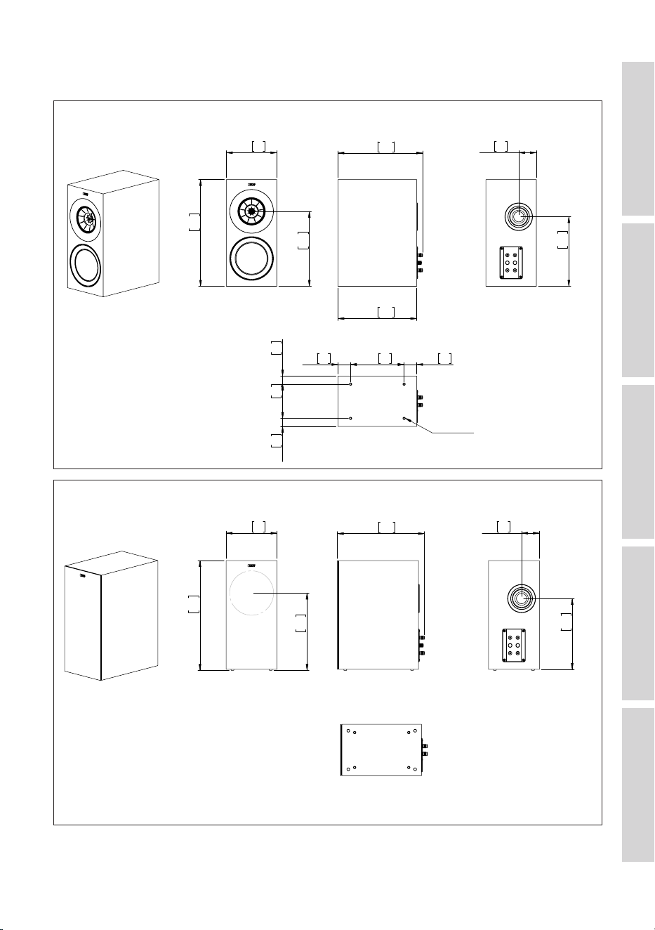
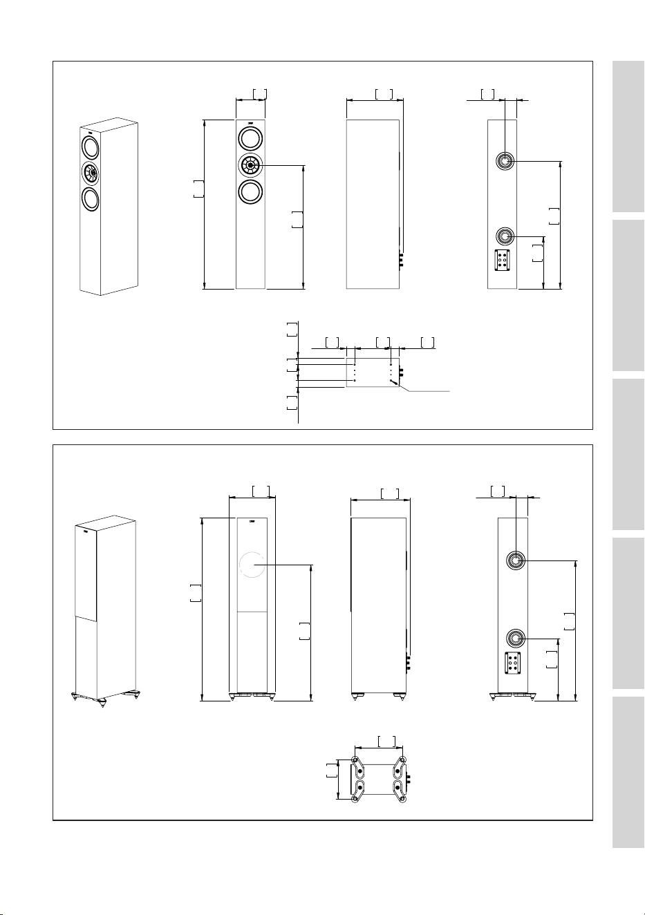
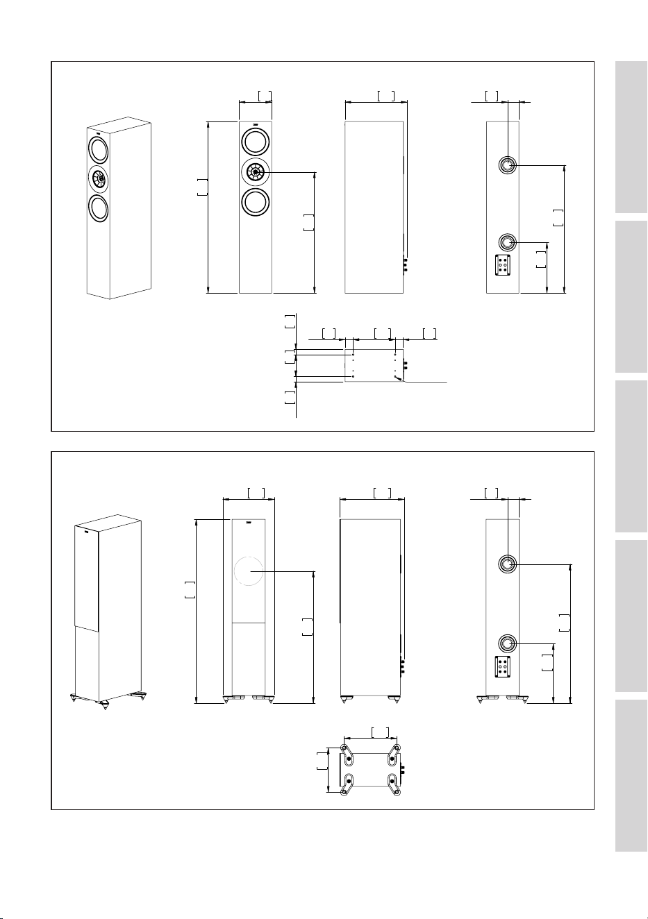
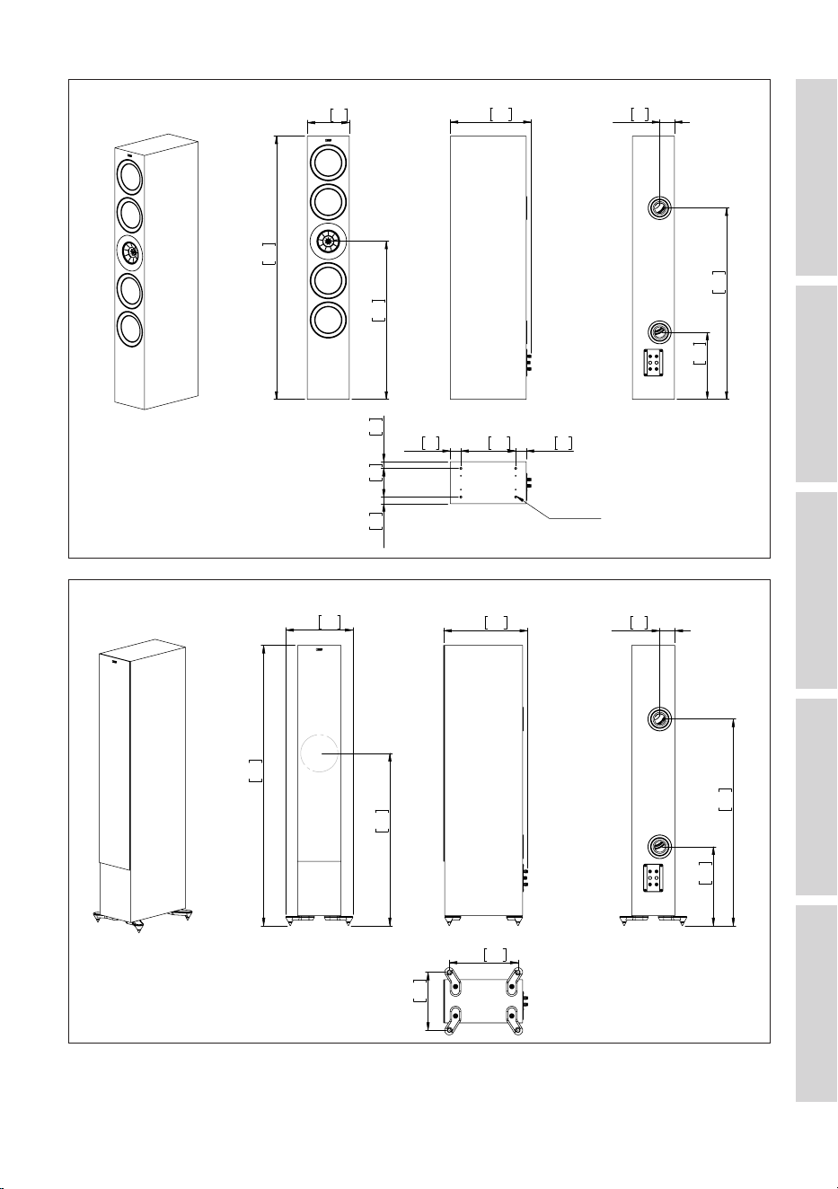
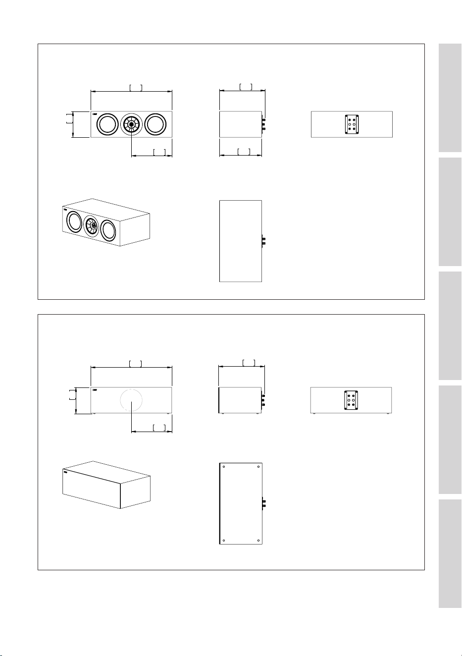
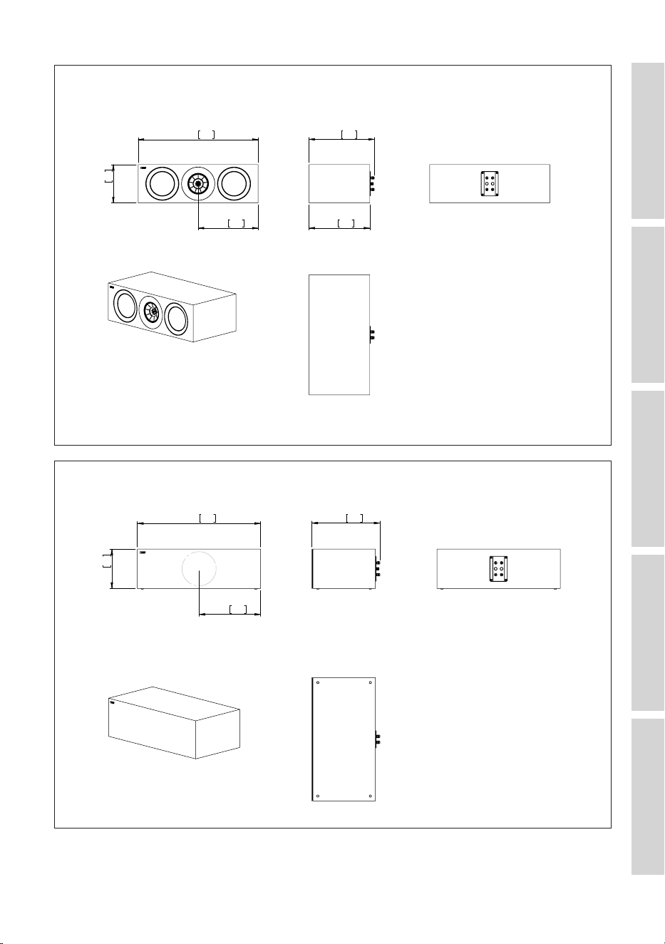
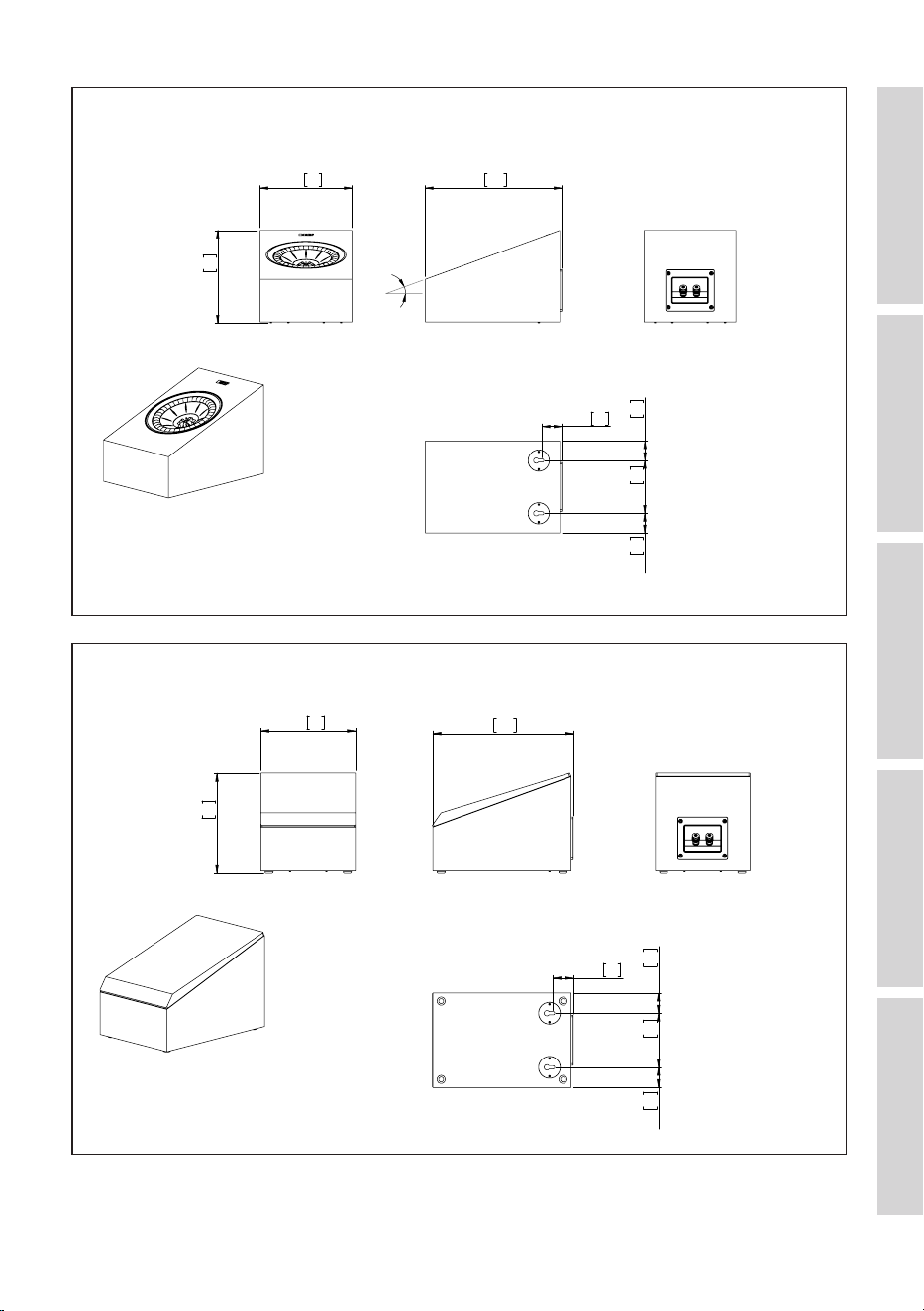
12.2 Dimensional Drawings
199.6
7.9
422.2
16.6
296.4
11.7
335.5
13.2
312.0
12.3
69.8
2.7
275.0
10.8
135.6
5.3
212.0
8.3
50.0
2.0
50.0
2.0
32.0
1.3
32.0
1.3
M8 Pitch 1.25
FRONT
SIDE
BACK
BOTTOM
UNIT: MM [INCH]
R3 Meta (1)
Front Side
Bottom
Unit: mm [inch]
Back
199.6
7.9
426.2
16.8
300.4
11.8
340.8 13.4
69.8
2.7
275.0
10.8
FRONT
SIDE
BACK
BOTTOM
UNIT: MM [INCH]
R3 Meta (2)
Front Side
Bottom
Back
Unit: mm [inch]
45
Table of ContentsInstallationPositioningConnectionsFAQ and Troubleshooting
174.6
6.9
1024.9
40.4
750.0
29.5
343.5
13.5 69.8
2.7
318.0
12.5
775.0
30.5
50.0
2.0
220.0
8.7
50.0
2.0
39.0
1.5
96.6
3.8
39.0
1.5
M8 Pitch 1.25
SIDE
BACK
BOTTOM
UNIT: MM [INCH]
FRONT
R5 Meta (1)
Front Side
Bottom
Unit: mm [inch]
Back
1071.4
42.2
796.5 31.4
271.6 10.7
348.8 13.7
69.8
2.7
364.5 14.4
821.5 32.3
278.0 10.9
229.6
9.0
SIDE
BACK
BOTTOM
UNIT: MM [INCH]
FRONT
R5 Meta (2)
Front Side
Bottom
Unit: mm [inch]
Back
46
Table of ContentsInstallationPositioningConnectionsFAQ and Troubleshooting
1062.4
41.8
199.6
7.9
750.0 29.5
383.5 15.1 69.8
2.7
313.0 12.3
792.0 31.2
50.0
2.0
260.0 10.2 50.0
2.0
32.0
1.3
135.6
5.3
32.0
1.3
M8 Pitch 1.25
SIDE
BACK
BOTTOM
UNIT: MM [INCH]
FRONT
R7 Meta (1)
Front Side
Bottom
Unit: mm [inch]
Back
1108.9
43.7
796.5
31.4
310.6
12.2
388.8
15.3 69.8
2.7
359.5
14.2
838.5
33.0
318.0
12.5
268.6
10.6
SIDE
BACK
BOTTOM
UNIT: MM [INCH]
FRONT
R7 Meta (2)
Front Side
Bottom
Unit: mm [inch]
Back
47
Table of ContentsInstallationPositioningConnectionsFAQ and Troubleshooting
199.6
7.9
1249.0
49.2
750.0 29.5
383.5 15.1
69.8
2.7
318.0 12.5
908.0 35.7
135.6
5.3
260.0 10.2 50.0
2.0
50.0
2.0
32.0
1.3
32.0
1.3
M8 Pitch 1.25
SIDE
BACK
BOTTOM
UNIT: MM [INCH]
FRONT
R11 Meta (1)
Front Side
Bottom
Unit: mm [inch]
Back
1295.5
51.0
310.6
12.2
796.5
31.4
388.8
15.3
69.8
2.7
364.5
14.4
954.5
37.6
268.6
10.6
318.0
12.5
SIDE
BACK
BOTTOM
UNIT: MM [INCH]
FRONT
R11 Meta (2)
Front Side
Bottom
Unit: mm [inch]
Back
48
Table of ContentsInstallationPositioningConnectionsFAQ and Troubleshooting
549.8 21.6
174.6 6.9
274.9 10.8
308.5 12.1
285 11.2
FRONT
SIDE
BACK
UNIT: MM [INCH]
BOTTOM
R2 Meta (1)
Front Side Back
Bottom
Unit: mm [inch]
549.8 21.6
178.6 7.0
274.9 10.8
313.8 12.4
FRONT
SIDE
BACK
UNIT: MM [INCH]
BOTTOM
R2 Meta (2)
Front Side Back
Bottom
Unit: mm [inch]
49
Table of ContentsInstallationPositioningConnectionsFAQ and Troubleshooting
624.8 24.6
199.6 7.9
312.4 12.3
339.5 13.4
316 12.4
FRONT
SIDE
BACK
UNIT: MM [INCH]
BOTTOM
R6 Meta (1)
Front Side Back
Bottom
Unit: mm [inch]
624.8 24.6
199.6 7.9
312.4 12.3
344.8 13.6
FRONT
SIDE
BACK
UNIT: MM [INCH]
BOTTOM
R6 Meta (2)
Front Side Back
Bottom
Unit: mm [inch]
50
Table of ContentsInstallationPositioningConnectionsFAQ and Troubleshooting
FRONT
SIDE
BACK
BOTTOM
UNIT: MM [INCH]
R8 Meta (1)
174.6
6.9
175.8
6.9
259.0 10.2
20°
37.3
1.5
37.3
1.5
100.0
3.9
37.3
1.5
Front Side Back
Bottom
Unit: mm [inch]
FRONT
SIDE
BACK
BOTTOM
UNIT: MM [INCH]
R8 Meta (2)
174.6
6.9
185.0
7.3
259.0
10.2
37.3
1.5
37.3
1.5
100.0
3.9
37.3
1.5
Front Side Back
Bottom
Unit: mm [inch]