USER’S MANUAL
EU510
OBDII/EOBD+CAN
EU510

1. Safety Precautions and Warnings
To prevent personal injury or damage to vehicles and/or the
scan tool, read this instruction manual first and observe the
following safety precautions whenever working on a vehicle:
Turn the ignition off first,then connect 16-pin to plug,then turn the
ignition on.
Always perform automotive testing in a safe environment.
Do not attempt to operate or observe the tool while driving a vehicle.
Operating or observing the tool will cause driver distraction and
could cause a fatal accident.
Wear safety eye protection that meets ANSI standards.
Keep clothing, hair, hands, tools, test equipment, etc. away from all
moving or hot engine parts.
Operate the vehicle in a well ventilated place: Exhaust gases are
Poisonous.
Put blocks in front of the drive wheels and never leave the vehicle
unattended while running tests.
Use extreme caution when working around the ignition coil,
distributor cap, ignition wires and spark plugs. These components
create hazardous voltages when the engine is running.
Put the transmission in PARK (for automatic transmission) or
NEUTRAL (for manual transmission) and make sure the parking
brake is engaged.
Keep a fire extinguisher suitable for gasoline/chemical/electrical
fires nearby.
Don't connect or disconnect any test equipment while the ignition is
on or the engine is running.
Keep the scan tool dry, clean, free from oil/water or grease. Use a
mild detergent on a clean cloth to clean the outside of the scan tool,
when needed.
1 EN

The first generation of On-Board Diagnostics (called OBD I) was developed by
the California Air Resources Board (CARB) and implemented in 1988 to monitor
some of the emission control components on vehicles. As technology evolved
and the desire to improve the On-Board Diagnostic system increased, a new
generation of On-Board Diagnostic system was developed. This second
generation of On-Board Diagnostic regulations is called "OBD II".
The OBD II system is designed to monitor emission control systems and key
engine components by performing either continuous or periodic tests of specific
components and vehicle conditions. When a problem is detected, the OBD II
system turns on a warning lamp (MIL) on the vehicle instrument panel to alert
the driver typically by the phrase “Check Engine” or “Service Engine Soon”. The
system will also store important information about the detected malfunction so
that a technician can accurately find and fix the problem. Here below follow
three pieces of such valuable Information:
OBD II Diagnostic Trouble Codes are codes that are stored by the on-board
computer diagnostic system in response to a problem found in the vehicle.
These codes identify a particular problem area and are intended to provide you
with a guide as to where a fault might be occurring within a vehicle. OBD II
Diagnostic Trouble Codes consist of a five-digit alphanumeric code. The first
character, a letter, identifies which control system sets the code. The other four
characters, all numbers, provide additional information on where the DTC
originated and the operating conditions that caused it to be set. Below is an
example to illustrate the structure of the digits:
2. General Information
2.1 On-Board Diagnostics (OBD) II
2.2 Diagnostic Trouble Codes (DTCs)
1) Whether the Malfunction Indicator Light (MIL) is commanded 'on' or 'Off';
2) Which, if any, Diagnostic Trouble Codes (DTCs) are stored;
3) Readiness Monitor status.
2 EN
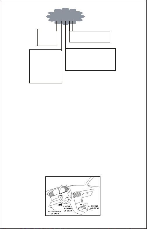
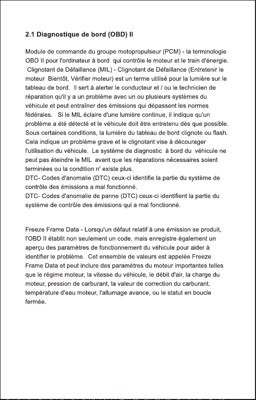
The DLC (Data Link Connector or Diagnostic Link Connector) is the
standardized 16-pin connector where diagnostic scan tools interface with the
vehicle's on-board computer. The DLC is usually located 12 inches from the
center of the instrument panel (dash), under or around the driver's side for most
vehicles. If the Data Link Connector is not located under the dashboard, a label
should be there revealing its location. For some Asian and European vehicles,
the DLC is located behind the ashtray and the ashtray must be removed to
access the connector. If the DLC cannot be found, refer to the vehicle's service
manual for the location.
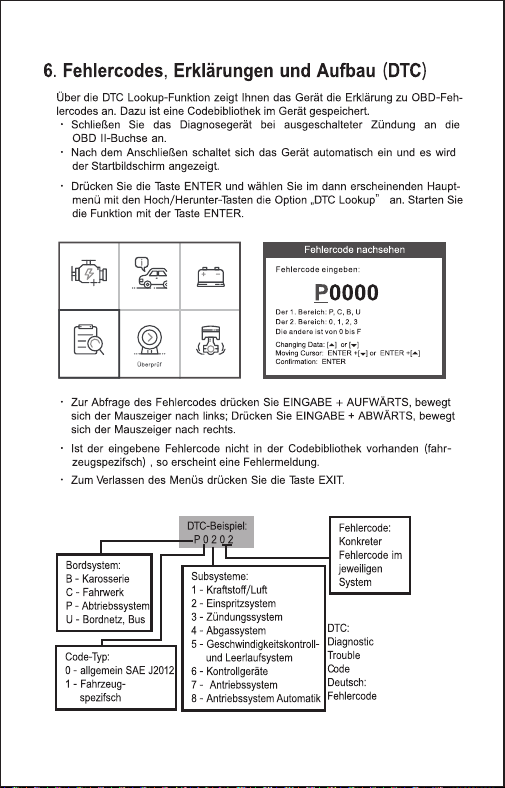
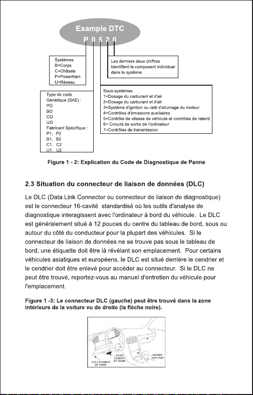
DTC Example
P 0 5 2 0
System s
B = Body
C = Chassis
P = Powertr ain
U = Network
Last two digits identify individual
component within the system
Code Typ e
Generic (SAE) :
P0
B0
C0
U0
Man u facturer Specif ic:
P1, P2
B1, B2
C1, C2
U1, U2
Su b -syst em s
1 = Fuel and air metering
2 = Ignition system or engine misfire
3 = Auxiliary emissions controls
4 = Vehicle speed control and idle controls
5 = Computer output circuits
6 = Transmission controls
Figure 1-2: Explanation of a diagnostic trouble code.
2.3 Location of the Data Link Connector (DLC)
Figure 1-3: The DLC connector (left) can be found in the
area of the car interior seen at right (black arrow).
3 EN
3. Using the Scan Tool
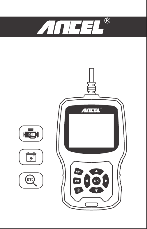
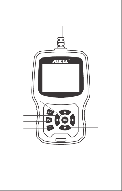
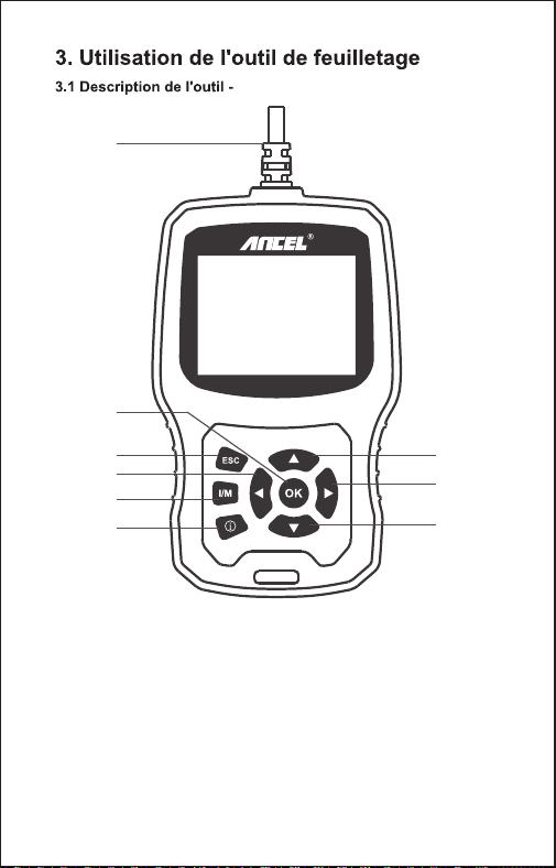
3.1 Tool Description - ANCEL EU510
1. OBDII Connector- Connect the tool to the vehicle’s Data Link
Connector(DLC).
2. OK BUTTON- Confirm a selection (or action) from a menu.
3. ESC BUTTON- Cancel a selection (or action) from a menu or returns to
the menu.
4. UP BUTTON - Moves up through menu and submenu items in menu
mode.
OBDII/EOBD+CAN
EU510
1
3
2
4
5
7
6
8
9
4 EN
5.DOWN BUTTON- Moves down through menu and submenu items in
menu mode.
6. LEFT BUTTON- When looking up datastream, if the datastream display
more than one screen, or turn page up or down when more than one page
is displayed.
7. RIGHT BUTTON- When looking up datastream, if the datastream
display more than one screen, or turn page up or down when more than
one page is displayed.
8. “I/M” BUTTON- Quick State Emissions readiness check and drive cycle
verification.
9. HELP BUTTON- Provides help information ,Press the help button will
obtain more the fault code explanation.
1) Display: 2.8” TFT 262K true color
2) Operating Temperature: 0 to 50℃ (32 to 140 Fº)
3) Storage Temperature: -20 to 70℃ (-4 to 158 Fº)
4) External Power: 8 to 36 V power provided via vehicle battery
5) Dimensions: 155.30 x 97.60 x 31.80 mm
6) Weight: 0.45kg
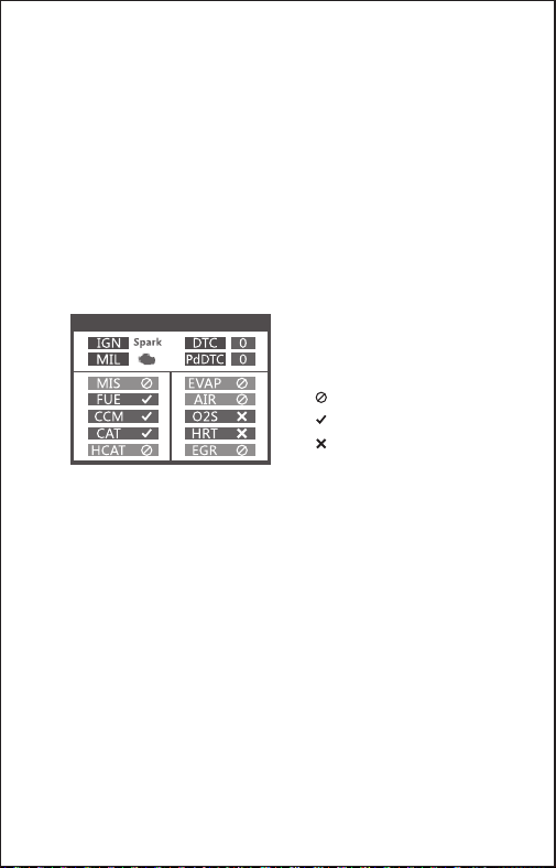
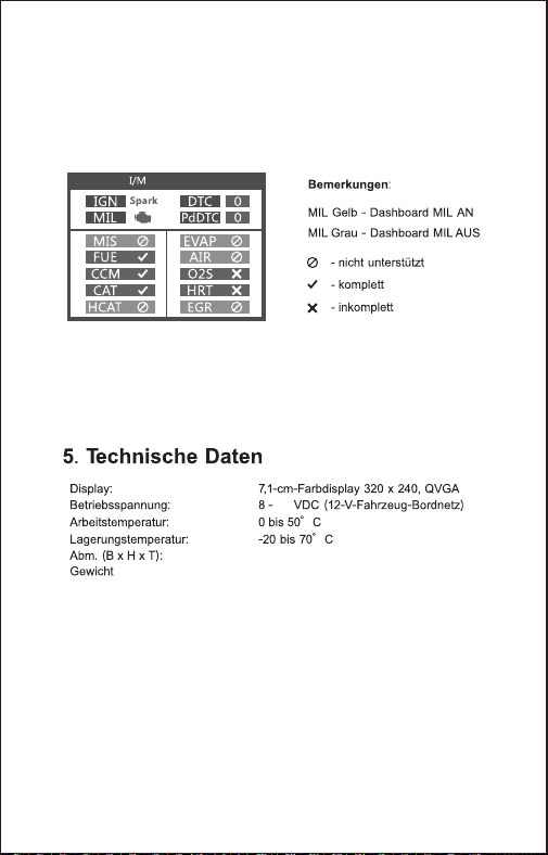
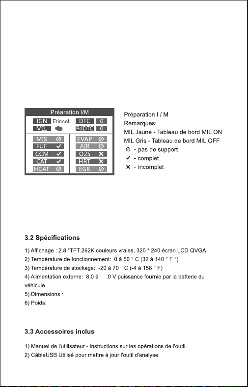
Remarks:
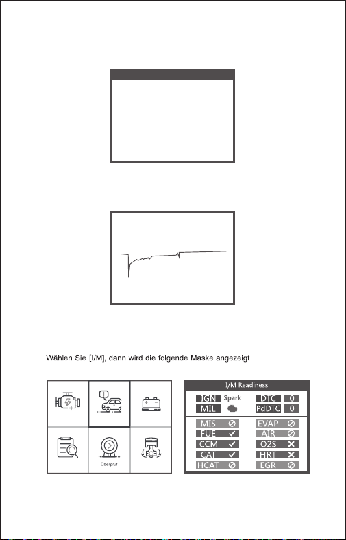
MIL Yellow- Dashboard MIL ON
MIL Gray-Dashboard MIL OFF
-not support
-complete
-not complete
I/M Readiness
3.2 Specifications
1) User's Manual -- Instructions on tool operations.
2) USB cable - Used to upgrade the scan tool.
3.3 Accessories Included
5 EN
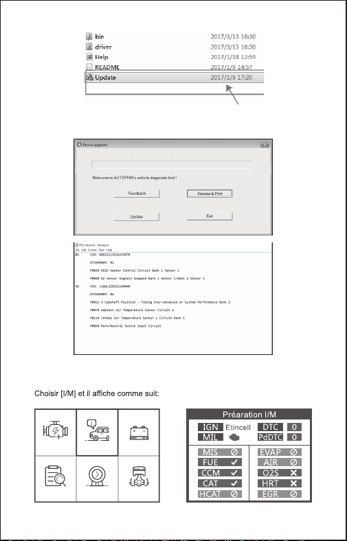
I/M Readiness
A snapshot of the emission systems operations for all OBD II vehicles -
i.e., misfire monitor, evap systems monitor and more. Choose [I/M] and
it displays as follow:
3.4 I/M
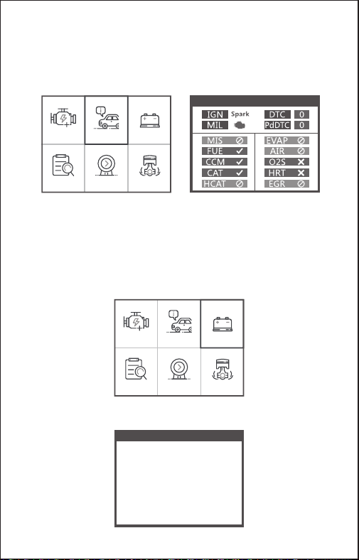
BAT Check
Turn off engine
OBDII I/M BAT
Lookup Review Setup
OBDII I/M BAT
Lookup Review Setup
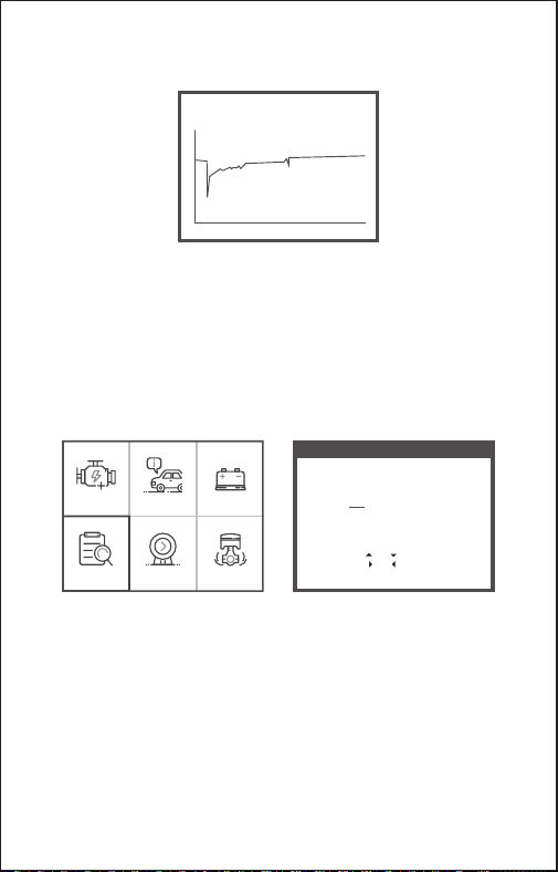
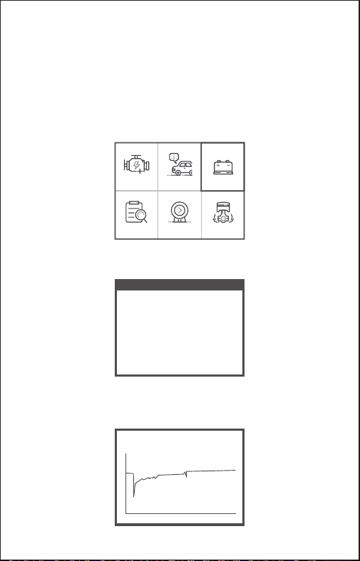
The function is used to read real time battery voltage. From the Main
Menu, use the left / right scroll button to select the BAT menu and press
the OK button. the screen will display the interface as shown below:
Please turn off the engine.
3.5 BAT Check
6 EN
OBDII I/M BAT
Lookup Review Setup
When press [OK] button and Start detection, it’s display interface:
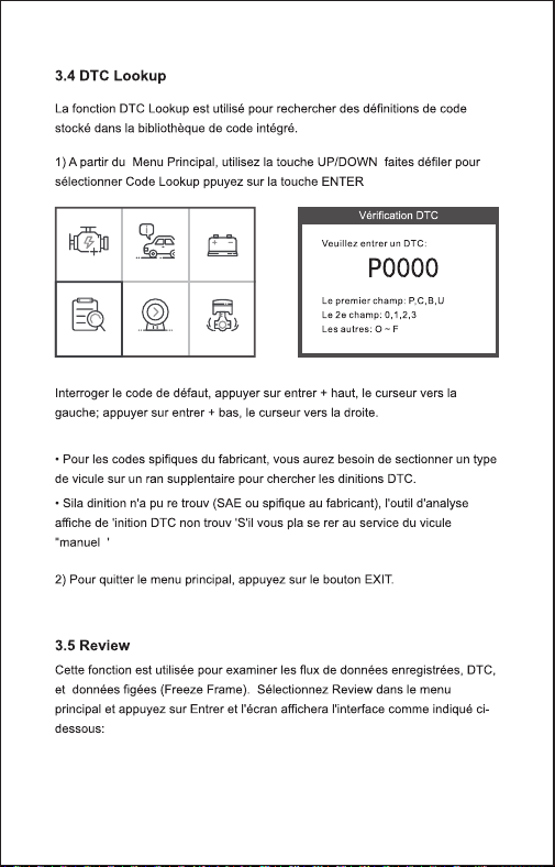
For manufacturer specific codes , you'll need to select a vehicle make
on an additional screen to look for DTC definitions.
If definition could not be found (SAE or Manufacturer Specific), the
scan tool displays "DTC definition not found! Please refer to vehicle
service"manual !"
2) To exit to the Main Menu, press the ESC button.
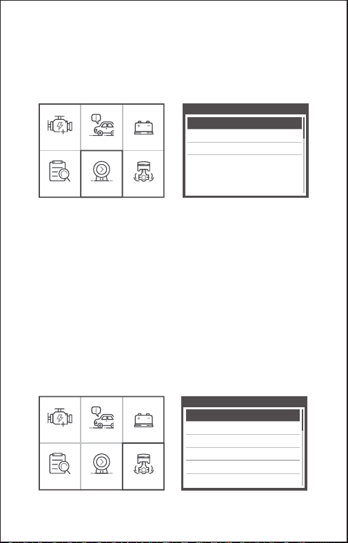
The DTC Lookup function is used to search for definitions of Code
stored in the built-in Code library.
1) From the Main Menu, use the LEFT /DOWN scroll button to select
the Code Lookup and press the OK button.
3.6 DTC Lookup
DTC Lookup
Please input DTC:
The 1st range : P , C , B , U
The 2nd range : 0 , 1 , 2 , 3
The others from : 0 to F
Changing Data: [ ] or [ ]
Moving Cursor: [ ] or [ ]
Confirmation: OK
P0000
Current voltage: 11.80V
Min: 0 mS End: 2731 mS
Off: 11.80V
Min: 7.26V
Max: 12.46V
7 EN
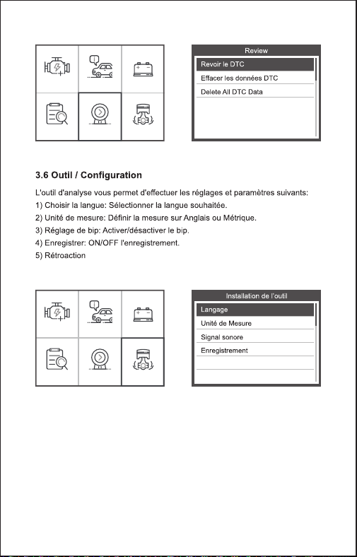
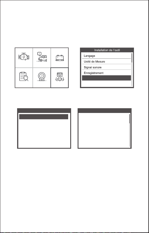
1) Select Language: Selects the desired language.
2) Unit of Measure: Set measure to English or Metric.
3) Beep Set: Turns ON/OFF beep.
4) Record: ON/OFF the Record.
5) Feedback.
6) About: Product information.
Tool Setup
Language
Unit of Measure
Beep
Record
Feedback
About
OBDII I/M BAT
Lookup Review Setup
OBDII I/M BAT
Lookup Review Setup
Review
Review DTC
Delete DTC Date
Delete All DTC Date
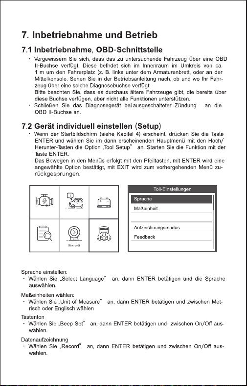
This function is used to review the recorded DTC. Select Review in the
Main Menu and press OK and the screen will display the interface as
shown below:
3.7 Review
The scan tool allows you to make the following adjustments and
settings:
3.8 Tool Setup
8 EN
Choose [About] and it displays as follow:
Tool Information
Software Version:
Hardware Version:
Serial Number:
Supported:
01.62.000
01.10.000
ANCEL20180300000001
OBD-II/EOBD
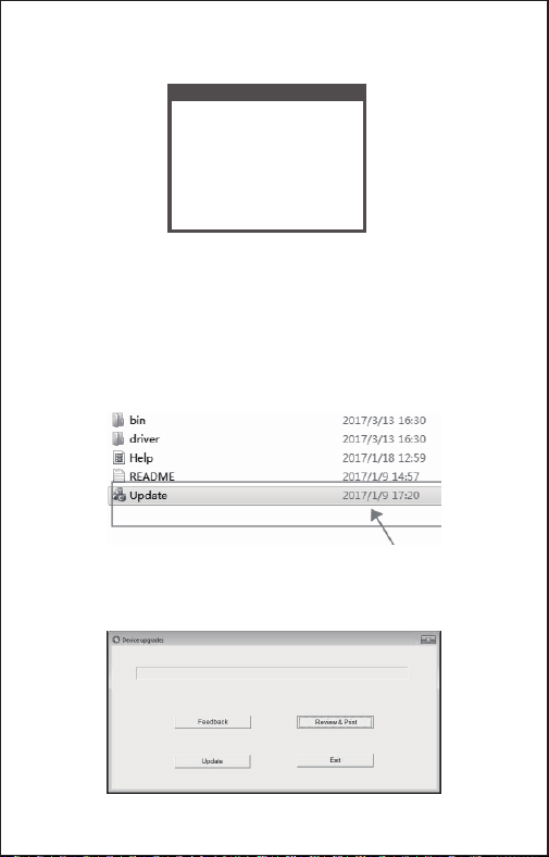
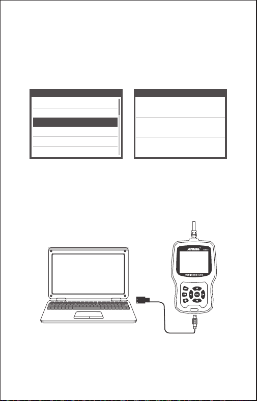
4. Click ”Review&Print” and automatically generate diagnostic reports.
1. Download upgrade file from ANCEL website.
2. The device is connected with computer through USB cable.
3. Open the “update” application.
3.9 Review&Print diagnostic reports
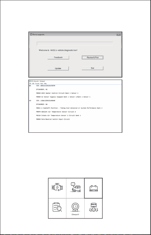
Welcome to ANCEL’s vehicle diagnostic tool !
9 EN
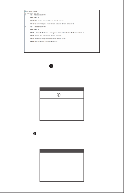
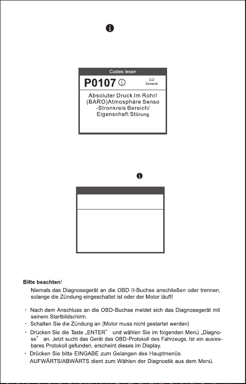
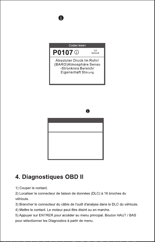
1.When the device read the fault codes, the screen will display the
codes as shown below:
3.10 Help Function
2. if users view the help icon picture in the menu, please press the help
function key , it can read more about the codes information, and why
this fault codes occurred. the screen will display the help information as
shown below:
Read Codes
P0123
Throttle/Pedal Position Sensor/
Switch A Circuit High"
1/2
General
DTC HELP
P0123
1/2
General
Possible Cause:
1.Faulty throttle position sensor
2.Throttle position sensor harness
is open or shorted
3.Throttle position sensor circuit poor
electrical connection
10 EN
CAUTION: Don't connect or disconnect any test equipment with
ignition on or engine running.
1) Turn the ignition off.
2) Locate the vehicle's 16-pin Data Link Connector (DLC).
3) Plug the scan tool cable connector into the vehicle's DLC.
4) Turn the ignition on. Engine can be off or running.
5 ) Press OK to enter Main Menu . UP /DOWN button to select
Diagnostics from the menu.
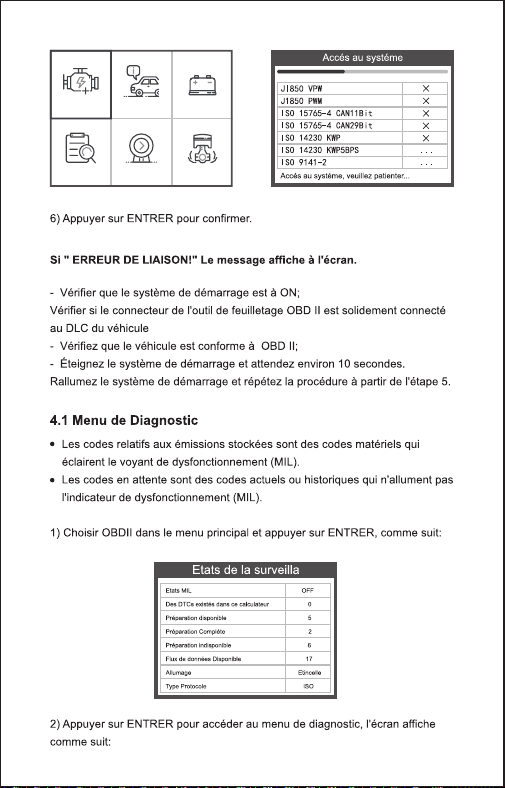
4. OBD II Diagnostics
OBDII I/M BAT
Lookup Review Setup
6) Press OK to confirm.
If "LINKING ERROR!" message shows on the display.
- Verify that the ignition is ON;
- Check if the scan tool's OBD II connector is securely connected to
the vehicle's DLC;
- Turn the ignition 'off' and wait for about 10 seconds. Turn the
ignition back to 'on' and repeat the procedure from step 5.
View Data
JI850 VPW
J1850 PWM
ISO 15765-4 CAN11Bit
ISO 15765-4 CAN29Bit
ISO 14230 KWP
ISO 14230 KWP5BPS
ISO 9141-2
×
×
×
×
×
...
...
Entering system please wait...
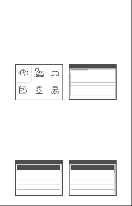
1. Vehicles that comply with the OBD2 protocols support these features:
[Read codes], [Erase codes], [Data stream], [Vehicle information].
Diagnostic Menu
Read Codes
Erase Codes
I/M Readiness
Data Stream
Freeze Frame
O2 Sensor Test
Diagnostic Menu
On-Board Monitioring
Evap System Test
Vehicle Information
11 EN

When the vehicle has no fault code, the device displays the following menu
prompts:
For example 2: [Evap System Test]Function: The Evaporative Emission
Control System (EVAP) is used to prevent gasoline vapors from escaping into
the atmosphere from the fuel tank and fuel system. OBDII monitors the
vehicle’s EVAP system, the device sends a signal, different vehicles will
respond differently.
2. Whether the menu function can read the relevant data, the situation of
different brand vehicles is different, subject to actual test.[IM Readiness,
Freeze frame、O2 Sensor test, On-Board monitoring, Evap system test ]
For example 1:Freeze frame refers to the moment when the fault occurs,
some of the most important parameter values of the engine .When the vehicle
has a fault code, the device displays the following menu prompts:
2.1 When the vehicle supports the EVAP test, the device displays the following
menu prompts:
Freeze Frame
LONGFT1
MAP
RPM
VSS
SPARKADV
IAT
0.0%
0.0kPa
0/min
0km/h
5.0°
-40℃
Datastream
The vehicle does not have
freeze frame data.
12 EN

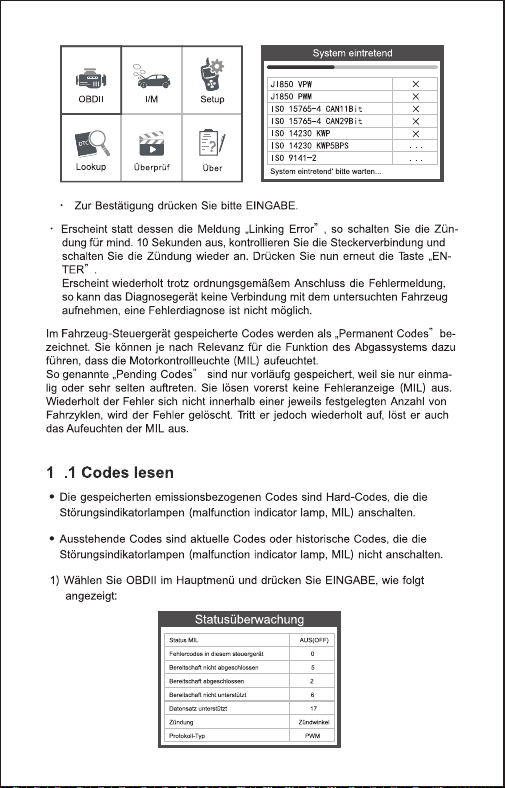
1) Select OBDII in Main Menu and press OK, shown as follow :
stored emission-related codes is hard codes which illuminate
malfunction indicator lamp(MIL).
pending codes is current codes or historical codes which will not
illuminate malfunction indicator(MIL).
4.1 Diagnostic Menu
MIL Status
DTCs in this ECU
Readiness Supported
Readiness Completed
Readiness Not Supported
Datastream Suppored
Ignition
Protocol Type
ON
3
8
5
3
66
Spark
VPW
Monitor Status
2.2 When the vehicle does not support the EVAP test, the device displays the
following menu prompts:
Evaporative system leak
test passed
Evap System Test
Evaporative system leak
test not supported
Evap System Test
13 EN

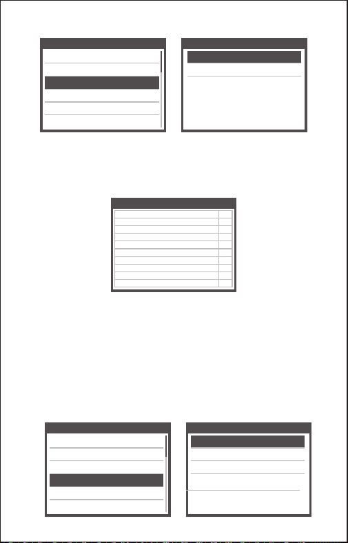
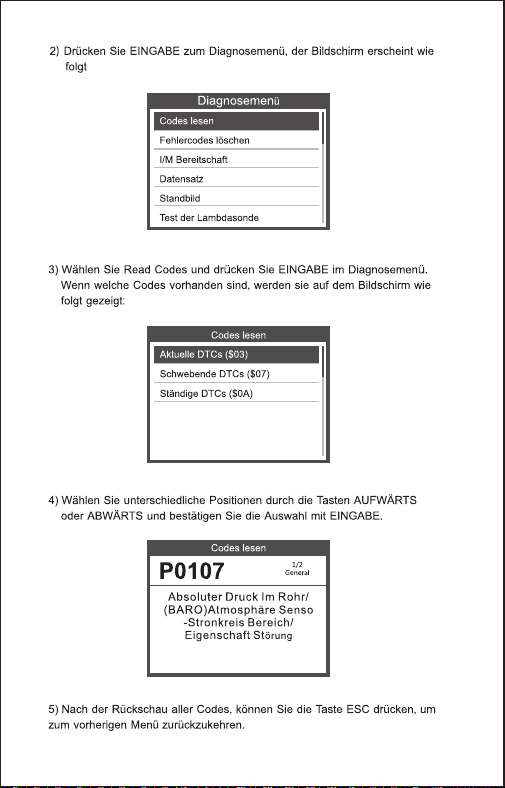
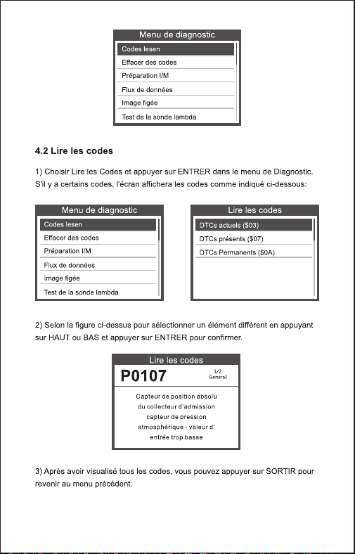
1) Select Read Codes and press OK in Diagnostic Menu. If there are
some codes, the screen will display the codes as shown below:
4.2 Read Codes
Read Codes
Current DTCs ($03)
Pending DTCs ($07)
Permanent DTCs ($0A)
2) Press OK to the Diagnostic Menu, screen will display as follow :
Diagnostic Menu
Read Codes
Erase Codes
I/M Readiness
Data Stream
Freeze Frame
O2 Sensor Test
2) According to the above figure to select different item by pressing UP
or DOWN and press OK to confirm.
3) After viewing all the codes, you can press ESC to return to the
previous menu.
Read Codes
P0107
Manifold Absolute
Pressure/Barometric
Pressure Circuit Low
1/2
General
14 EN

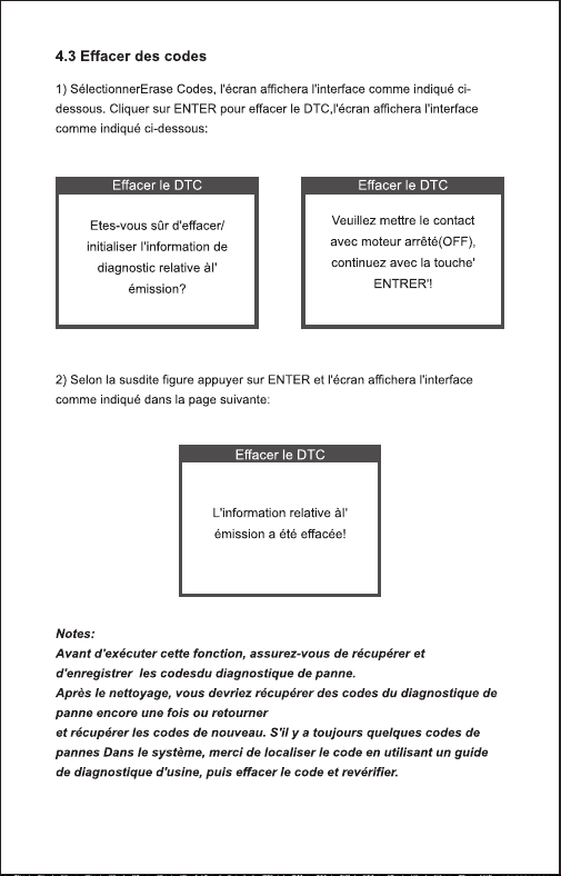
2) According to the above figure to press OK and the screen will display
the interface as shown on the next page:
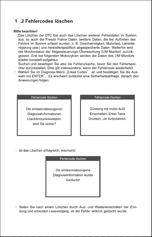
1) Select Erase Codes, the screen will display the interface as shown
below. Press OK to erase DTC's, and the screen will display the
interface as shown below:
4.3 Erase Codes
Erase DTC
Clear/Reset Emission-
Related Diagnostic
Information,Are you sure?
Erase DTC
Please Turn lgnition ON
with Engine Off Press
enter key to continue!
Erase DTC
Emission-Related
Diagnostic Information has
been Cleared!
Before performing this function, make sure to retrieve and record the
trouble codes.
After clearing, you should retrieve trouble codes once more or turn
ignition on and retrieve codes again. If there are still some trouble
codes in the system, please troubleshoot the codes using a factory
diagnosis guide, then clear the codes and recheck.
Notes:
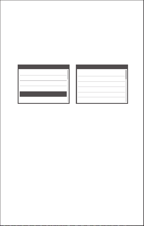
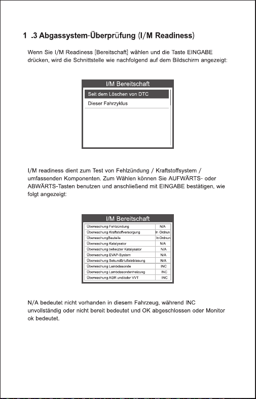
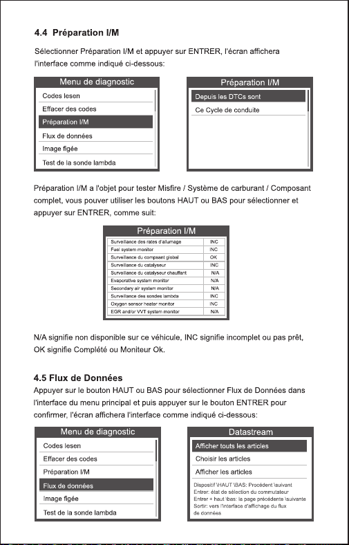
Select I/M Readiness and press OK, the screen will display the
interface as shown below:
4.4 I/M Readiness
15 EN
I/M readiness is to test Misfire / Fuel system / Comprehensive
component, You can use UP or DOWN button to select and press OK
shown as follow :
Diagnostic Menu
Read Codes
Erase Codes
I/M Readiness
Data Stream
Freeze Frame
O2 Sensor Test
Since DTCs Were Cleared
This Drive Cycle
I/M Readiness
N/A means not available on this vehicle, INC means incomplete or not
ready, OK means Completed or Monitor Ok.
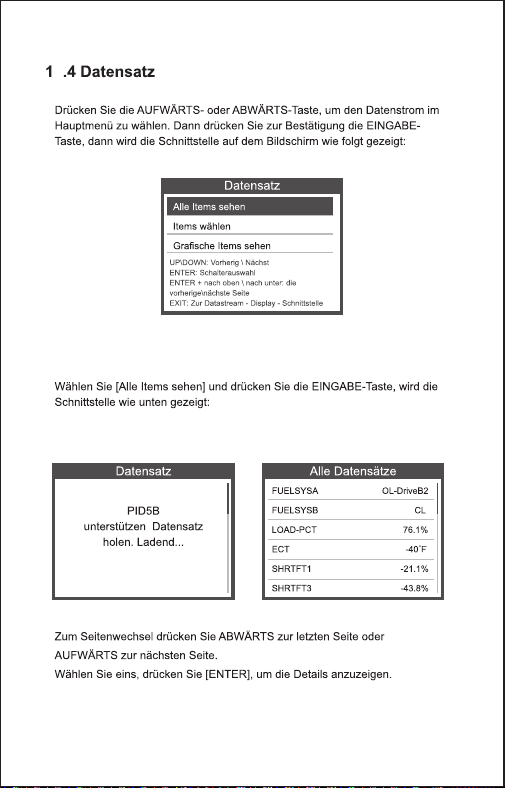
Press UP or DOWN button to select Data Stream in Main Menu
interface and then press OK button to confirm, the screen will display
the interface as shown below:
4.5 Data Stream
Diagnostic Menu
Read Codes
Erase Codes
I/M Readiness
Data Stream
Freeze Frame
O2 Sensor Test
I/M Readiness
Misfire monitor
Fuel system monitor
Comprehensive component monitor
Catalyst monitor
Heated catalyst monitor
Evaporative system monitor
Secondary air system monitor
Oxygen sensor monitor
Oxygen sensor heater monitor
EGR and/or VVT syetem monitor
N/A
N/A
OK
N/A
N/A
N/A
N/A
INC
INC
INC
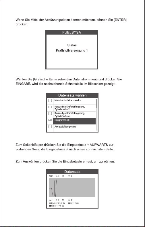
View All Items
Select Items
View Graphic Items
Datastream
16 EN

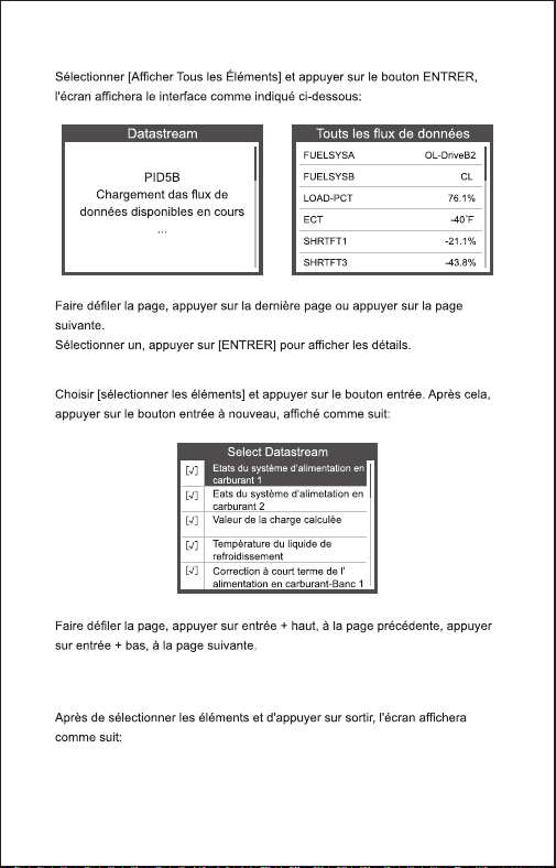
Select [ View All Items ] and press OK button, the screen will display
the interface as shown below:
Datastream
PID07
Get supported data
stream.Loading...
All Datastream
FUELSYSA
FUELSYSB
LOAD_PCT
ECT
SHRTFT1
LONGFT1
OL
N/A
0.0%
53℃
32.8%
0.0%
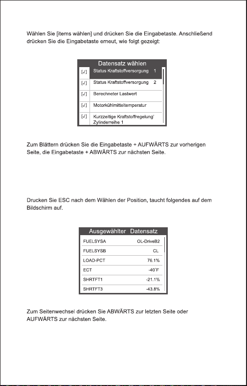
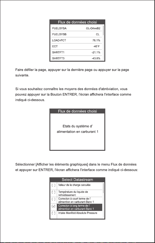
After selected items and press ESC, the screen will display as follow:
Choose [ select items ] and press OK button. After that, press OK
button again, shown as follow:
FUELSYSA
FUELSYSB
LOAD_PCT
ECT
SHRTFT1
OL
N/A
0.0%
53℃
32.8%
Selected Datastream
[ ]
[ ]
[ ]
[ ]
[ ]
Select Datastream
Fuel system 1 status
Fuel system 2 status
Calculated LOAD Value
Engnie Coolant Temperature
Short Term Fuel Trim-Bank1
√
√
√
√
√
17 EN
FUELSYSA
Fuel system 1 status
[ ]
[ ]
[ ]
[ ]
[ ]
Select Datastream
√
Engine Coolant Temperature
Short Term Fuel Trim-Bank2
Short Term Fuel Trim-Bank4
Intake Manifold Absolute Pressure
Intake Air Temperature
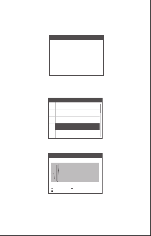
Data Stream
max 0.0 95 0.0
min
LOAD_PCT=0.0%
SHRTFT1=0.0%
ECT=95℃
0.0 95 0.0
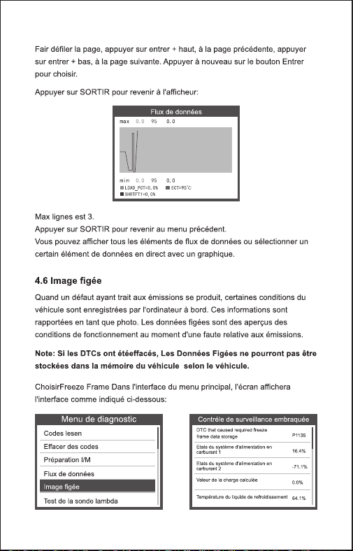
Press OK to select [ View Graphic Items ] in Data stream menu, after
selected items, the screen will display the interface as shown below:
Press ESC to return to display :
Max lines is 3.
Press ESC to return to previous menu.
You can view all data stream items or select a certain item of live data
with a graph.
If you want to know means of the abbreviation data, you can press the
OK Button, the screen will display the interface as shown below:
18 EN
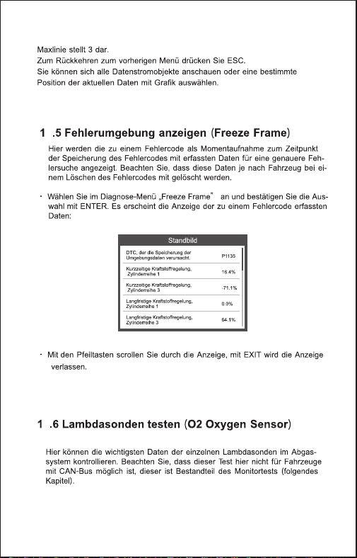
When an emission-related fault occurs, a snapshot of current vehicle
parameter are recorded by the ECU.
Note: if DTCs were erased, Freeze Data may not be stored in vehicle.
4.6 View Freeze Frame
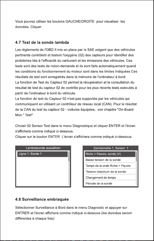
OBD II regulations set by the SAE require that relevant vehicles
monitor and test the oxygen (O 2) sensors to identify problems related
to fuel efficiency and vehicle emissions. These tests are not on-demand
tests and they are done automatically when engine operating
conditions are within specified limits. These test results are saved in the
on-board computer's memory.
The O2 Sensor Test function allows retrieval and viewing of O2 sensor
monitor test results for the most recently performed tests from the
vehicle's on-board computer.
The O2 Sensor Test function is not supported by vehicles which
communicate using a controller area network (CAN). For O2 Sensor
Test results of CAN-equipped vehicles, see chapter "On-Board Mon.
Test".
4.7 O2 sensor test
Diagnostic Menu
Read Codes
Erase Codes
I/M Readiness
Data Stream
Freeze Frame
O2 Sensor Test
Select Freeze Frame in main menu interface, the screen will display the
interface as shown below:
You can use UP/ DOWN button to view the data. Press ESC to return
to Diagnostic Menu.
Freeze Frame
LONGFT1
MAP
RPM
VSS
SPARKADV
IAT
0.0%
0.0kPa
0/min
0km/h
5.0°
-40℃
19 EN

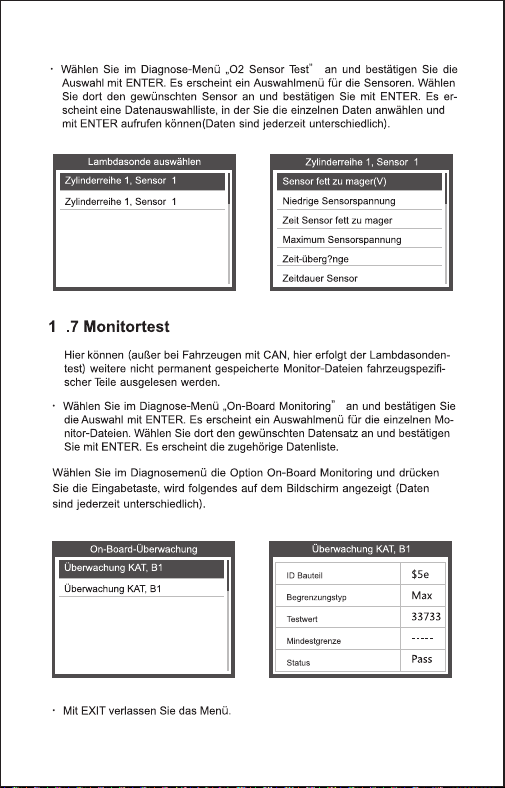
You can use UP or DOWN button to select an item and press OK, the
screen will display as shown below (Data will be different everytime):
Bank1-Sensor2
Select O2 Sensor
Rich to lean sensor(V)
Lean to rich sensor(V)
Minmum sensor voltage
Maximum sensor voltage
Time transitions
Bank1-Sensor2
Select O2 Sensor Test in Diagnostic menu and press OK and the
Screen will display as shown below (Data will be different everytime) :
This function can be utilized to read the results of on-board diagnostic
monitoring . Tests for specific components/systems.
Select On-board Monitoring in Diagnostic Menu and press OK and the
screen will display as shown below (Data will be different everytime):
4.8 On-board monitor test
Diagnostic Menu
On-Board Monitoring
Evap System Test
Vehicle Information
Test $02 Data
Test $03 Data
Test $05 Data
Test $08 Data
Test $0B Data
On-Board Monitoring
20 EN

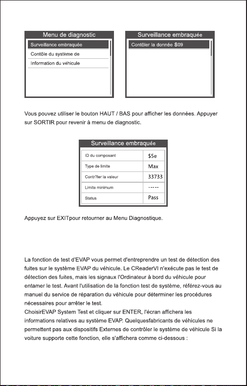
Press ESC to return to Diagnostic Menu.
On-Board Monitoring
Compnent ID
Limit Type
Test Value
Minimum Limit
Status
$5e
Max
33733
-----
Pass
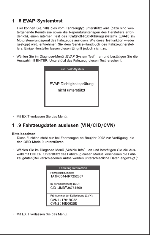
The EVAP test function lets you initiate a leak test for the vehicle's
EVAP system. The device does not perform the leak test, but signals to
vehicle's on-board Computer to initiate the test. Before using the
system test function, refer To The vehicle's service repair manual to
determine the procedures necessary to stop the test.
Select EVAP System Test and press OK, the screen will display the
relative information about EVAP system. Some vehicle manufacturers
do not allow External devices to control vehicle system. If the car
supports this function, it will display as below:
4.9 EVAP System Test
Diagnostic Menu
On-Board Monitoring
Evap System Test
Vehicle Information
Evaporative system leak
test not supported
Evap System Test
21 EN
Diagnostic Menu
On-Board Monitoring
Evap System Test
Vehicle Information
Select [Vehicle Info] and press OK, the screen will display the
information, such as VIN (Vehicle identification Number), CID
(Calibration ID) and CVN (Calibration verification number), as shown
below (different cars will shown different data) :
Press ESC to return to Diagnostic Menu.
4.10 Vehicle Info
LCFJD52E76H008345
Vehicle Identification Number(VIN):
CID1:WD2211562A155070
Calibration Identifications(CID):
CVN:E95898A6
Calibration Verifition Numbers(CVN):
Vehicle information
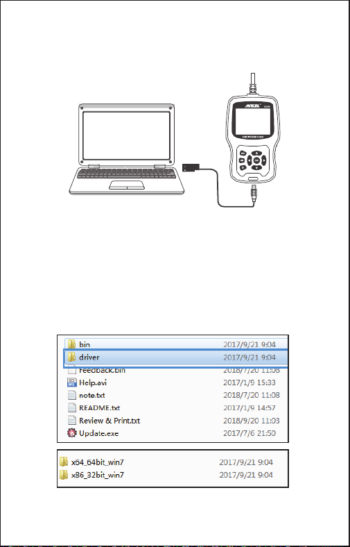
The device is connected with computer through USB cable.
1) When upgrade the device software, it only supports window 7/8/10
system.
2) It can be updated directly on Window8 and window10 system.
5. Update
22 EN
OBDII I/M BAT
Lookup Review Setup
6. Feedback
Tool Setup
Language
Unit of Measure
Beep
Record
About
Feedback
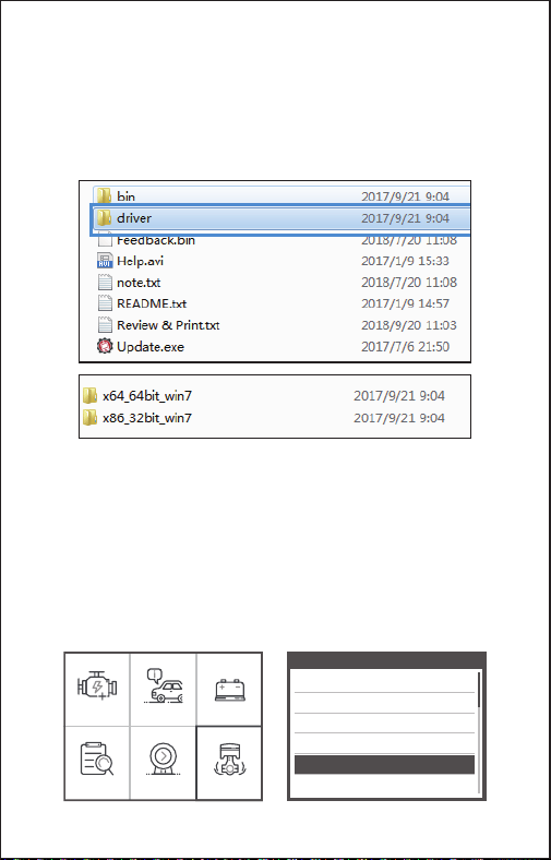
3) When the computer is window7 system, the device’s software driver
is installed on the computer.
The 64-bit operating system select “X64_64bit_win7” files
The 32-bit operating system select “X86_32bit_win7” files
Note: the detail operation method, please view the [Help.avi] file.
1.When the [OBDII] function shows connected error with vehicle,
please using the feedback function.
Choose [Feedback] and it displays as follow:
23 EN
Feedback
Start recording
Feedback
Automatic recording is
ready,perform the related
functions that require
feedback.
After the execution,
disconnect the car,
connect to the computer
via USB use the update.
Choose [Start recording] to open record function and it displays as
follow:
Next : Press ESC Button and return to the main menu.
Choose [OBDII] menu to detecting again and it will record the data.
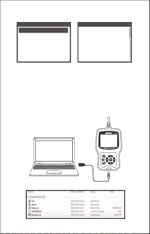
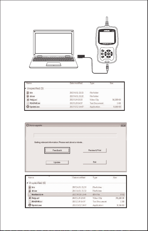
2. Transfer data to your computer and generate feedback file.
Download upgrade file on the computer from ANCEL website.
The device is connected with computer through USB cable.
Choose “Update” file and it displays as follow:
24 EN
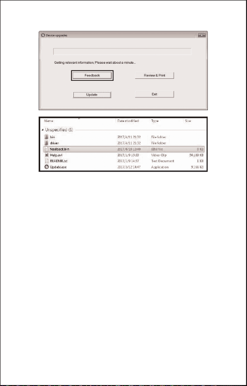
Please send the feedback.bin file to [email protected].
Click “Feedback” and it displays as follow:
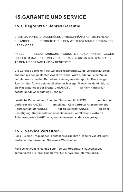
7. Warranty and Service
THIS WARRANTY IS EXPRESSLY LIMITED TO PERSONS WHO
PURCHASE ANCEL EU510 PRODUCTS FOR PURPOSES OF RESALE OR
USE IN THE ORDINARY COURSE OF THE BUYER'S BUSINESS.
ANCEL EU510 code reader is warranted against defects in materials and
workmanship for one year (12 months) from the date of delivery to the user.
This warranty does not cover any part that has been abused, altered, used for
a purpose other than for which it was intended, or used in a manner
inconsistent with instructions regarding use. The exclusive remedy for any
automotive meter found to be defective is repair or replacement, and ANCEL
EU510 shall not be liable for any consequential or incidental damages.
7.1 Limited One Year Warranty
If you have any questions, please contact your local store distributor.
If it becomes necessary to return the scan tool for repair, contact your local
distributor for more information.
7.2 Service Procedures
25 EN
26 DE
27 DE
OBDII/EOBD+CAN
EU510
1
3
2
4
5
7
6
8
9
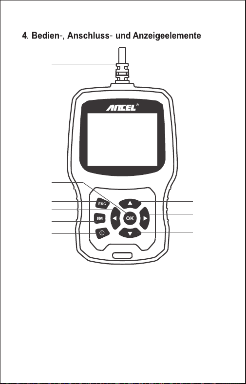
1. OBDII-Anschluss
2. OK-Taste zur Auswahl von Menüfunktionen
3. ESC-Taste zum Verlassen von Menüs und für spezielle Setup-Funktionen
4. Taste Hoch zum Bewegen in Menüs und in Anzeigen mit mehreren
Bildschirmseiten
5. Taste Herunter zum Bewegen in Menüs und in Anzeigen mit mehreren
Bildschirmseiten
6. LINKE TASTE - Beim Aufrufen des Datenstroms, wenn der Datenstrom
mehr als einen Bildschirm anzeigt, oder blättern Sie die Seite nach oben oder
unten, wenn mehr als eine Seite angezeigt wird
28 EN
Bereitschaft
7. RECHTS-TASTE - Beim Aufrufen des Datenstroms, wenn der Datenstrom
mehr als einen Bildschirm anzeigt, oder blättern Sie die Seite nach oben oder
unten, wenn mehr als eine Seite angezeigt wird
8. „I/M“-Taste – Schnellstatus Emissions-Bereitschaftsprüfung und
Fahrzyklusüberprüfung.
9. HILFE-TASTE-Bietet Hilfeinformationen. Drücken Sie die Hilfetaste, um
weitere Informationen zum Fehlercode zu erhalten
36
155.30 x 97.60 x 31.80 mm
0.45kg
29 DE
OBDII I/M BAT
Lookup Einstellun
30 DE
OBDII I/M BAT
Lookup Einstellun
Piepston
Über
31 DE
OBDII I/M BAT
Lookup Einstellun
8. Review-Funktion
9. Rückschau und Drucken von
Diagnoseberichten
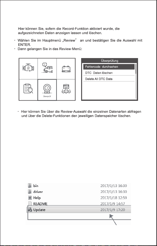
1. Laden Sie die Upgrade-Datei von der ANCEL-Website herunter.
2. Das Gerät ist über ein USB-Kabel mit dem Computer verbunden.
3. Öffnen Sie die Anwendung „Update“.
32 DE
OBDII I/M BAT
Lookup Einstellun
10. BAT Check
Die Funktion dient zum Lesen der Batteriespannung in Echtzeit. Verwenden Sie
im Hauptmenü links / rechts Blättern Sie mit der Pfeiltaste zum BAT-Menü und
drücken Sie die OK-Taste. Der Bildschirm zeigt die Schnittstelle wie folgt an:
4. Klicken Sie auf "Überprüfen & Drucken" und generieren Sie automatisch
Diagnoseberichte.
33 DE
BAT Check
Motorabschaltung
Current voltage: 11.80V
Min: 0 mS End: 2731 mS
Off: 11.80V
Min: 7.26V
Max: 12.46V
Bitte schalten Sie den Motor aus.
Wenn Sie die Taste [OK] drücken und die Erkennung starten, erscheint die
Anzeige:
OBDII I/M BAT
Lookup Einstellun
11. I/M
34 DE
1.Wenn das Gerät die Fehlercodes gelesen hat, zeigt der Bildschirm
die Codes wie folgt an:
2. Wenn Benutzer das Hilfesymbolbild im Menü anzeigen, drücken Sie
bitte die Hilfefunktionstaste. Sie können mehr Informationen über die
Codes und warum diese Fehlercodes aufgetreten sind. Der Bildschirm
zeigt die Hilfeinformationen wie folgt an:
DTC HELP
P0107
1/2
General
Possible Cause:
1.Faulty throttle position sensor
2.Throttle position sensor harness
is open or shorted
3.Throttle position sensor circuit poor
electrical connection
12. Hilfefunktion
13. Fehlercodes auslesen
35 DE
3
36 DE
37 DE
3
38 DE
3
39 DE
3
40 DE
41 DE
42 DE
3
3
43 DE
3
44 DE
3
3
45 DE
13. Aktualisieren
Das Gerät ist über ein USB-Kabel mit dem Computer verbunden.
1) Beim Upgrade der Gerätesoftware wird nur das Windows 7/8/10-System
unterstützt.
2) Es kann direkt auf dem Window8- und Window10-System aktualisiert
werden.
3) Wenn der Computer ein window7-System ist, wird der Softwaretreiber des
Geräts auf dem Computer installiert.
Das 64-Bit-Betriebssystem wählt "X64_64bit_win7" -Dateien aus
Das 32-Bit-Betriebssystem wählt "X86_32bit_win7" -Dateien aus
Hinweis: Die detaillierte Operationsmethode finden Sie in der Datei {Help.avi}.
46 DE
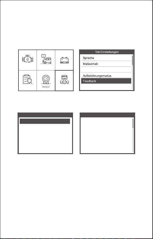
14. Feedback
1.Wenn die Funktion [OBDII] einen verbundenen Fehler mit dem Fahrzeug
anzeigt, verwenden Sie bitte die Feedback-Funktion.
Wählen Sie [Feedback] und es wird wie folgt angezeigt:
Wählen Sie [Start recording], um die Aufnahmefunktion zu öffnen. Die Anzeige
wird wie folgt angezeigt:
Weiter: Drücken Sie die ESC-Taste und kehren Sie zum Hauptmenü zurück.
Wählen Sie das [OBDII] -Menü zur erneuten Erkennung und die Daten werden
aufgezeichnet.
2. Übertragen Sie Daten auf Ihren Computer und erstellen Sie eine
Feedback-Datei.
Laden Sie die Upgrade-Datei von der ANCEL-Website auf den Computer
herunter.
Feedback
Start recording
Feedback
Automatic recording is
ready,perform the related
functions that require
feedback.
After the execution,
disconnect the car,
connect to the computer
via USB use the update.
OBDII I/M BAT
Lookup Einstellun
Piepston
Über
47 DE
Das Gerät ist über ein USB-Kabel mit dem Computer verbunden.
Wählen Sie "Update" aus und es wird wie folgt angezeigt:
Klicken Sie auf "Feedback" und es wird wie folgt angezeigt:
Bitte senden Sie die feedback.bin -Datei an [email protected]
48 DE
EU510
EU510
EU510
EU510
EU510 EU510
EU510
www.anceltech.com
EU510
49 DE
50 FR
51 FR
52 FR
53 FR
1. OBD II CONNECTEUR - Connecter l'outil d'analyse au Connecteur Liaison
de Données (DLC) du véhicule.
2. BOUTON OK - Confirmer une sélection (ou une action) à partir d'un menu.
3. BOUTON ESC - Annuler une sélection (ou action) à partir d'un menu ou
retourner au menu.
4. BOUTON DÉFILEMENT VERS LE HAUT - Déplacer ver le haut l'élément
individuel dans un menu.
5. BOUTON DÉFILEMENT VERS LE BAS - Déplacer ver le bas l'élément
individuel dans un menu.
ANCEL EU510
OBDII/EOBD+CAN
EU510
1
3
2
4
5
7
6
8
9
54 FR
6. BOUTON DE GAUCHE - Lors de la recherche d’un flux de données, si
celui-ci affiche plusieurs écrans, ou si la page est affichée en haut ou en bas
lorsque plusieurs pages sont affichées.
7. BOUTON DROIT — Lorsque vous consultez le flux de données, si celui-ci
affiche plusieurs écrans, ou tournez la page vers le haut ou le bas lorsque
plusieurs pages sont affichées.
8. BOUTON "I/M" – Émissions Rapides pour la préparation de vérification et le
cycle de conduite.
9. BOUTON D'AIDE-Fournit des informations d'aide, appuyez sur le bouton
d'aide pour obtenir plus d'explications sur le code d'erreur.
36
155.30 x 97.60 x 31.80 mm
0.45kg
55 FR
OBDII I/M BAT
Recherch Révision Configur
56 FR
1. Téléchargez le fichier de mise à niveau à partir du site Web d'ANCEL
2. Le périphérique est connecté à l'ordinateur via un câble USB.
3. Ouvrez l'application «update»
3.7 Examiner et imprimer les rapports de diagnostic
OBDII I/M BAT
Recherch Révision Configur
OBDII I/M BAT
Recherch Révision Configur
Feedback
A propos de
6) A propos de
57 FR
4. Cliquez sur «Review & Print» et générez automatiquement des rapports de
diagnostic
OBDII I/M BAT
Recherch Révision Configur
3.8 I/M
58 FR
OBDII I/M BAT
Recherch Révision Configur
BAT Check
Turn off engine
La fonction est utilisée pour lire la tension de la batterie en temps réel.
Depuis le menu principal, utilisez les boutons gauche / droite faites
défiler avec le bouton de défilement pour sélectionner le menu BAT et
appuyez sur le bouton OK. l'écran affichera l'interface comme indiqué
ci-dessous:
S'il vous plaît éteindre le moteur.
Lorsque vous appuyez sur le bouton [OK] et démarrez la détection, son
interface d’affichage:
3.9 Test de batterie
Current voltage: 11.80V
Min: 0 mS End: 2731 mS
Off: 11.80V
Min: 7.26V
Max: 12.46V
59 FR
1.Wenn das Gerät die Fehlercodes gelesen hat, zeigt der Bildschirm
die Codes wie folgt an:
2. Wenn Benutzer das Hilfesymbolbild im Menü anzeigen, drücken Sie
bitte die Hilfefunktionstaste. Sie können mehr Informationen über die
Codes und warum diese Fehlercodes aufgetreten sind. Der Bildschirm
zeigt die Hilfeinformationen wie folgt an:
DTC HELP
P0107
1/2
General
Possible Cause:
1.Faulty throttle position sensor
2.Throttle position sensor harness
is open or shorted
3.Throttle position sensor circuit poor
electrical connection
3.10 Hilfefunktion
60 FR
OBDII I/M BAT
Recherch Révision Configur
61 FR
62 FR
63 FR
64 FR
65 FR
66 FR
67 FR
68 FR
4.9 Contôle du système de
69 FR
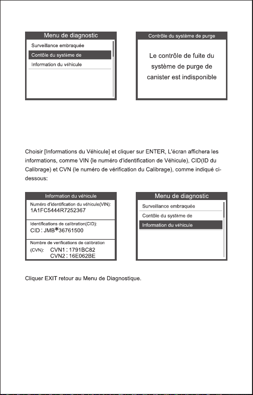
4.10 Information du véhicule
70 FR
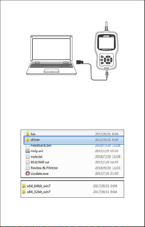
1) Lors de la mise à niveau du logiciel du périphérique, celui-ci prend
uniquement en charge le système Windows 7/8/10.
2) Il peut être mis à jour directement sur le système Window8 et window10.
3) Lorsque l’ordinateur est un système window7, le pilote logiciel de l’appareil
est installé sur l’ordinateur.
Le système d'exploitation 64 bits sélectionne les fichiers «X64_64bit_win7».
Le système d'exploitation 32 bits sélectionne les fichiers «X86_32bit_win7».
Remarque: pour la méthode d’opération de détail, veuillez consulter le fichier
{Help.avi}.
Le périphérique est connecté à l'ordinateur via un câble USB.
5. Mettre à jour
71 FR
OBDII I/M BAT
Recherch Révision Configur
Feedback
A propos de
6. Retour d'information
1.Lorsque la fonction [OBDII] indique une erreur de connexion avec le
véhicule, veuillez utiliser la fonction de retour.
Choisissez [Commentaires] et il s’affiche comme suit:
Feedback
Start recording
Feedback
Automatic recording is
ready,perform the related
functions that require
feedback.
After the execution,
disconnect the car,
connect to the computer
via USB use the update.
Choisissez [Démarrer l’enregistrement] pour ouvrir la fonction d’enregistrement.
Suivant: Appuyez sur la touche ESC pour revenir au menu principal.
Choisissez le menu [OBDII] pour détecter à nouveau et il enregistrera les
données.
2. Transférer des données sur votre ordinateur et générer un fichier de
commentaires.
Téléchargez le fichier de mise à niveau sur l'ordinateur à partir du site Web
d'ANCEL.
72 FR
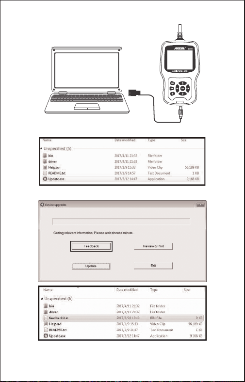
Le périphérique est connecté à l'ordinateur via un câble USB.
Choisissez le fichier «Update» et il s’affiche comme suit:
Cliquez sur "Commentaires" et il apparaît comme suit:
Veuillez envoyer le fichier feedback.bin à [email protected] .
73 FR
CETTE GARANTIE EST SPECIALEMENT LIMITÉE AUX PERSONNES QUI
ACHÈTENT DES PRODUITS ANCEL EU510 A DES FINS DE LA REVENTE OU
L'UTILISATION DANS LE COURS NORMAL DE L'AFFAIRE DE L'ACHETEUR.
Le produit électronique ANCEL EU510 est garanti contre toute défectuosité de
matériel et de fabrication pendant un an (12 mois) de la date de livraison à
l'utilisateur.
Cette garantie ne couvre aucune partie qui a été consommée, changée, utilisée
pour un but autre que pour laquelle elle a été destinée, ou utilisée d'une façon
incohérente quant aux instructions d'utilisation. Le remède exclusif à n'importe
quel compteur d'automobile jugé défectueux est la réparation ou le remplacement
et ANCEL EU510 ne sera responsable d'aucun dommage consécutif ou
accidentel.
La détermination finale des défauts sera faite par ANCEL EU510 conformément
aux procédures établies par ANCEL EU510. Aucun agent, salarié, ou
représentant d’ANCEL EU510 n'a le pouvoir de lier ANCEL EU510 à n'importe
quelle affirmation, représentation, ou garantie concernant des compteurs
d'automobiles ANCEL EU510, sauf comme déclaré dans le présent texte.
74 FR

Address: Runfeng office longhua district Shenzhen
GuangDong 518000 P.R.China
Tel: 0755-81751202
E-mail: [email protected]
Website: www.anceltech.com