
Technical Support and E-Warranty Certificate www.vevor.com/support
Water Descaler
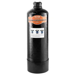
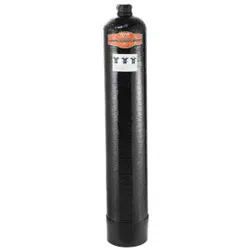
MODEL:0926/1054
We continue to be committed to provide you tools with competitive price.
"Save Half", "Half Price" or any other similar expressions used by us only
represents an estimate of savings you might benefit from buying certain tools
with us compared to the major top brands and does not necessarily mean to cover
all categories of tools offered by us. You are kindly reminded to verify carefully
when you are placing an order with us if you are actually Saving
Half in comparison with the top major brands.
- 1 -
MODEL:0926/1054
NEED HELP? CONTACT US!
Have product questions? Need technical support? Please feel free to
contact us:
Technical Support and E-Warranty Certificate
www.vevor.com/support
This is the original instruction, please read all manual instructions
carefully before operating. VEVOR reserves a clear interpretation of our
user manual. The appearance of the product shall be subject to the
product you received. Please forgive us that we won't inform you again if
there are any technology or software updates on our product.
Water Descaler

- 2 -
Warning-To reduce the risk of injury, user must read
instructions manual carefully.
1.INTRODUCTION
This descaler system has been engineered
to provide you with optimally clean water.The system features scale control
media with salt-free technology that naturally and safely reduces scale
buildup on internal pipes and plumbing without the use of harsh salt or
chemicals.Whatever your water needs —from hydration to cooking and
more — VEVOR has you covered.
Keep this owner's manual to reference installation,troubleshooting,and
filter replacement information.
2. SPECIFICATIONS & FEATURES
Max capacity:1300-2200T(340,000-580,000),4~5year
2300-4200T(600,000-1,100,000),6~7year
Min working pressure:0.14Mpa(20.31Psi)
Max working pressure:0.6Mpa(87.02Psi)
Min operating temperature:5°C(41℉)
Max operating temperature:38°C(100.4℉)
3.SAFETY
1. READ ALL INSTRUCTIONS.
To clean your system,wipe exterior with a damp cloth.Do not use any
strong abrasive cleaning agent or solvent cleaner.
• Properly tighten all fittings to ensure a leak-free assembly.

- 3 -
• Pick an appropriate installation location.Dimensions of systems vary
—always allow an estimated minimum of 28"clearance for height of tank.
• Unit must be installed in an area where the main water line enters your
home, before connecting to the water heater.DO NOT install after a water
heater or on the hot water line.
• It is recommended your system be installed indoors and out of direct
sunlight.
Prolonged exposure to light can weaken plastic components,resulting in
filter housing failure.If this is not possible and the system is outdoors or in a
sunny area, the unit must be protected from both direct sunlight and
freezing temperatures.
• Some local codes may require the use of a licensed plumber or certified
installer when disrupting a potable water line.
• Due to the varieties of home design,not all installation configurations can
be addressed in this guide.
• In areas with high pressure,a pressure relief valve and a water hammer
arrest or may be necessary.
• For use with municipally treated water only.Do not use with water that is
microbiologically unsafe or of unknown water quality without adequate
disinfection before or after the system.
Before installing:
• Do not install this filter where the line pressure may exceed 100 psi.
The operating pressure range for this filter is between
0.14Mpa~0.6Mpa(20.31-87.02Psi). Install on cold water lines only
(5-38℃)(41-100.4℉).Protect unit from freezing.
• Installation of the descaler system must comply with existing state and
local
plumbing codes.VEVOR and its manufacturer is not liable for
consequential or incidental damages due to improper installation.
• Do not install the unit on its side.It must be installed upright to maximize
contact with media bed.
• Improper sequence of equipment will affect performance and could

- 4 -
possibly damage your system.
Safety
warning
The machine should be operated by professional or others
have been trained;
• Foamed material flammable, the user may not arbitrarily
discarded or dispose, should be in accordance with the
relevant provisions of the state by the designated department
recycling.
SAVE THESE INSTRUCTIONS
CAUTION: Changes or modifications not expressly approved by the party
responsible for compliance could void the user's authority to operate the
equipment!
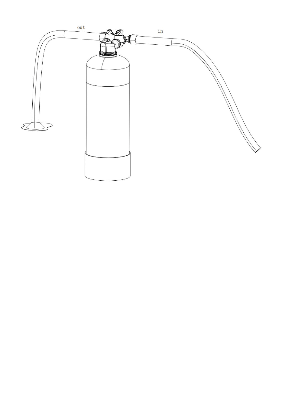
4.BEFORE USE
Note:It's imperative that this system is flushed properly prior to final
installation.
1.Slowly turn faucet on and allow discolored water to flow from outlet into a
suitable drainage area.
2.After an initial 15-minute flushing,begin a period of "surge flushing" by
turning water supply on for 30 seconds and
then off for 30 seconds,repeating cycle for 15 minutes or until initial surge
Of water is completely clear and free from discoloration and cloudiness.
3.Disconnect the system from the garden hose and position it for final
installation.
- 5 -
Note: Do not drink flushed water.
1.Pick an appropriate installation location.Unit must be installed in an area
where the main water line enters your home,before connecting to the water
heater.
Note:DO NOT install after the water heater or on the hot waterline.
Components and installation will vary.
2.Turn off the main water source prior to installation and drain water from
lines.
3.Wrap your 3/4" or 1" male NPT fittings with NSF certified plumber's
tape.Connect the 3/4" or 1" male fittings to the system's inlet and outlet.
Note:DO NOT use pipe solvent (dope),assolvents in some types of pipe
dope may cause damage to plastic fittings.Do not over-tighten to prevent
damage to filter head.
5.TRANSPORTATION AND MAINTENANCE:
- 6 -
6.OPERATION:
Please read entire manual to ensure all parts listed are present before
installation.
If any part is missing or damaged let us know by calling your company's
contact information Do not attempt to install the descaler.a
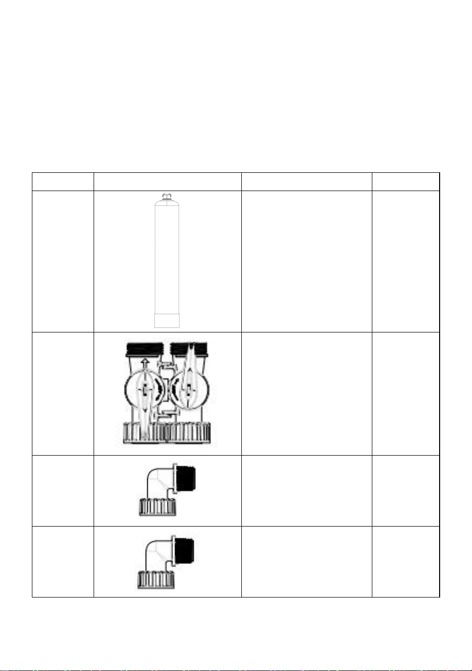
7.Decomposition table:
NO
PART
Specification
QTY
1
0926 or 1054
1
2
/
1
3
3/4 inch NPT/BSPT
2
4
1 inch NPT/BSPT
2
- 7 -
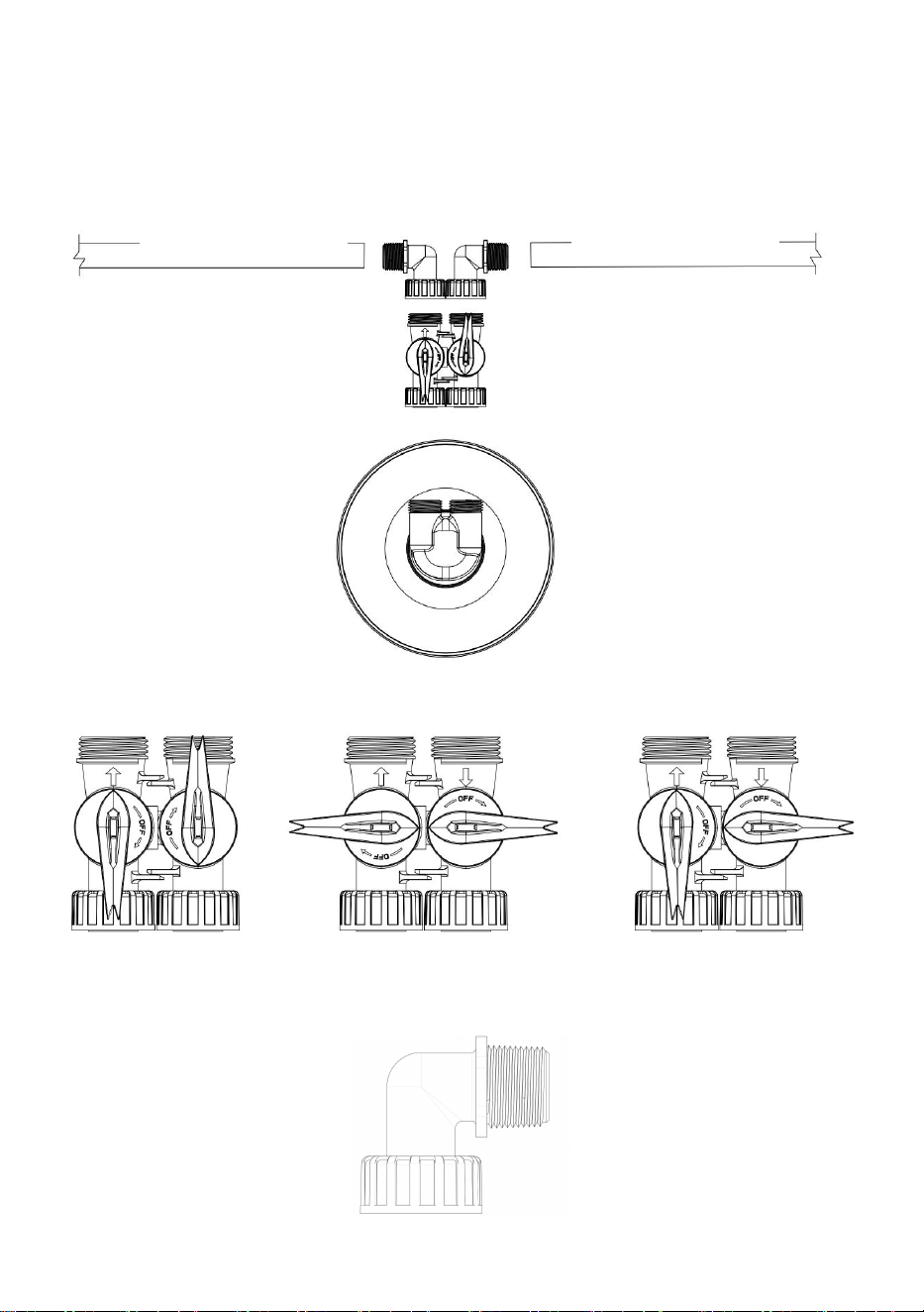
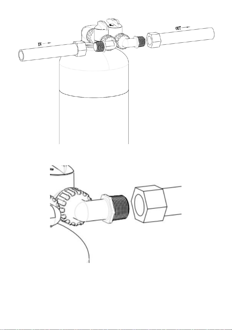
8.Assembly cue:
Installation diagram
Schematic diagram of bypass handle position:
Working position position at bypass position on off
Bend joint:
Water outlet 1
inch or 3/4 inch
Water inlet 1
inch or 3/4 inch
NO.3/NO.4
NO.2
NO.1
- 8 -
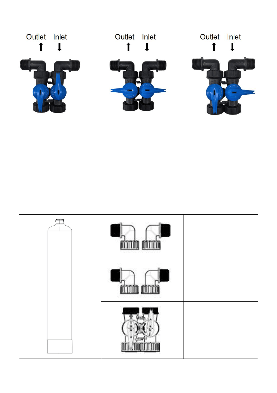
Foolproof design:
Working position Position at Bypass Position on Off
1.Working Position:Raw water →resin tank→water outlet flows out and
equipment runs normally.
2.Position at Bypass:Raw water →water inlet outlet flows out, when resin
is replaced or downstream maintenance is carried out.
3.Position on Off:In other cases,the water inlet is closed.
Accessory diagram:
3/4 inch NPT/BSPT
1 inch NPT/BSPT
Bypass
- 9 -
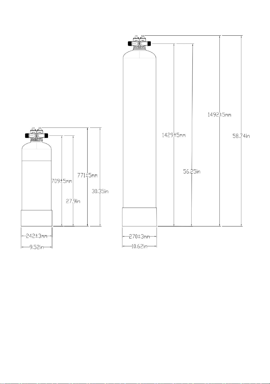
Installation height diagram
0926 1054
- 10 -