


22
Contents
Contents .......................................................................... 2
Revision History ...................................................................................4
Log in ...................................................................................................5
Introducing VSS ...................................................................................6
Key Features ........................................................................................6
Installation Option - OpenVPN ............................................................. 8
Chapter 1 Basics: ......................................................... 11
Control and Elements
................................................... 11
Live view ............................................................................................ 11
Search Panel ......................................................................................12
Playback Control ................................................................................ 12
Top Tool Bar .......................................................................................13
View cell control .................................................................................14
Text overlay ........................................................................................14
Hot Keys ...........................................................................................24
View Cell Elements ............................................................................27
Server and Client Components .......................................................... 30
Multiple Server Applications ...............................................................31
Chapter 2 Starting Up ................................................... 32
2-1. Selecting Devices .......................................................................33
2-2. Recording Options ......................................................................34
2-3. Storage .......................................................................................45
2-4. Starting Up - Main Page ..............................................................46
2-5. Saving a View .............................................................................49
2-6. Add More Live Views ..................................................................50
2-7. Save Your Preferences ...............................................................51
2-8. Customizable Layout ..................................................................53
2-9. Dashboard ..................................................................................55
2-10. E-Map .......................................................................................57
Placing DI/DO Devices .......................................................................60
Conguring GIS or Google Map and GPS .........................................61
2-11. Event Search .............................................................................67
2-12. PTZ Control ...............................................................................70
2-13. Playback ...................................................................................72
2-14. Alarm .........................................................................................80
2-15. Search Panel ............................................................................96
2-16. Smart search .............................................................................98
2-17. Tour .........................................................................................108
2-18. Thumbnail search ................................................................... 110
2-19. Deep search ............................................................................ 112
Chapter 3 Applications: .............................................. 116
3-1. I/O DI/DO Devices .................................................................... 116
IO Box and Related Conguration ................................................... 116

33
Conguring I/O Box DI/DO as a Trigger or Action in Alarm .............. 118
3-2. Conguring Redundant Servers - Failover................................ 122
Failover Conguration Process ........................................................ 129
3-3. VCA (Video Content Analysis) .................................................133
Prerequisites:
................................................................................133
3-4. VSS Software License ..............................................................146
Chapter 4 Settings: .................................................... 154
4-1. Settings > System > Preferences .............................................154
4-2. Settings > Device > Cameras ...................................................162
4-3. Logical Folders ..........................................................................165
4-4. Settings > Recording > Recording Options...............................168
4-5. Settings > Recording > Backup ...............................................170
Storage .............................................................................................173
4-6. Settings > Device > Stations .....................................................174
Multicasting ......................................................................................177
4-7. Settings > Device > Local DB ...................................................181
4-8. Settings > System > SMTP .......................................................185
4-9. Settings > IO Box and Related Conguration ........................... 185
4-10. Settings > User Management .................................................186
4-11. Settings > VIVOCloud .............................................................191
Appendix A: VSS Service Control Tool ..................... 195
Appendix B: Fisheye Camera Dewarp Modes .......... 196
Appendix C: Matrix .................................................... 203
Appendix D: Joystick Support ................................. 208
Appendix E: Network Audio Solution ...................... 214
Appendix F: Upload Device Pack ............................ 219
Appendix G: Using LPR Related Functions w/ Data Magnet 221
Appendix H: Enable Smart Tracking for Speed Dome Cameras 237
Appendix I: Multi-factor Authentication for Access Control 238

44
Revision History
Rev. 1.0:
* Initial release.
55
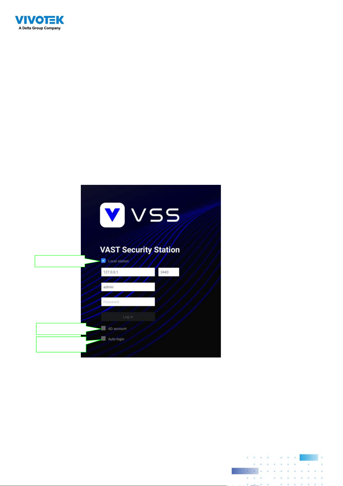
Log in
To log in,
1. Enter the server's IP address and TCP port number (3443 as the default). If logging in
from the server itself, you can select the Local station checkbox.
2. Enter the credentials for login. The credentials were created during the installation.
3. You can use an existing AD ccount for login. See page 190 for user management and AD
count configuration.
4. Auto login: After you enter the credentials for the first time, the server will not prompt for
credentials the next time you start the VSS software.
Login from the local machine
using a loop-back address
login using an existing AD
account
Automatically login after the
first time you entered the cre-
dentials

66
Introducing VSS
VIVOTEK VSS (VAST Security Station) is the professional video / central management
software designed for managing all VIVOTEK IP surveillance products with intuitive
functions and numerous features. It supports hundreds of cameras and stations in a
hierarchical structure of system for monitoring, recording, playback and event trigger
management with ease-of-use and efficient control.
VSS integrates VIVOTEK network cameras to provide diverse solutions and applications,
with the cameras for uninterrupted video recording, Smart Search II, Smart VCA, and
Cybersecurity management solution. VSS performs remote management with full range of
the server & client structure and constitutes a robust system for various applications, such
as stores, banking and the public space.
Key Features
• Deep Search wth attributes, scenes, and Re-search functions
• Smart Search II Plus: Dynamic Forensic Search
- Line Crossing: Detection of crossing a user-defined line and direction
- Loitering: Detection of Loitering in an area for a configurable stay time.
- Intrusion: Detection of intrusion into a zone or leaving from a zone.
• Smart Tracking: Speed Dome's People Tracking.
• Live Multicast: Reduced network traffic and optimized bandwidth usage.
• CMS Failover: 1+1 redundancy for Central Management server.
• Data Overlay on screen.
• User defined role for group authorities
• Recording encryption

77
• License plate recognition solution and data magnet
• Cybersecurity Management Solution
• Smart VCA: AI Powered Video Analytics
• System Overview dashboard
• Multi-sensor display modes
• Evidence Lock: Automatically Bookmark Related Recordings When Alarm Triggered.
• Evidence Export: Manually Export Video Recordings or Alarm Clips.
• Matrix for Video Wall Solution
• Automatic Problem Feedback Mechanism
• Multiple Fisheye Dewarp Modes
88
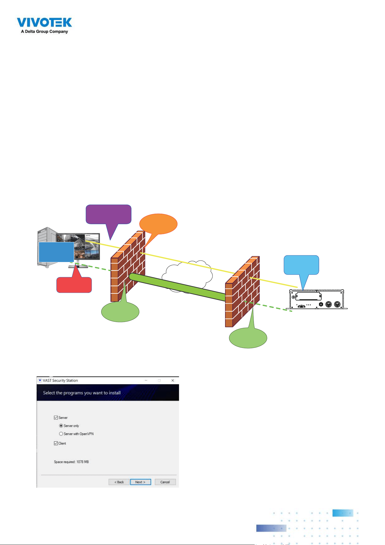
Installation Option -
OpenVPN
NAT-traversal with OpenVPN
You can select the "Server with OpenVPN" option when installing the VSS server. A remote
connection from NVR via a 3G/4G/LTE network can be made through an OpenVPN tunnel.
When the OpenVPN option is selected, an OpenVPN server will be installed with the VSS
server.
HMAC authentication and TLS encryption over an encrypted UDP connection are made ef-
fortlessly using the traversal methodology.
The sample installation screens are shown below:
VSS
Camera 01
Camera 02
Camera 03
Camera 04
Camera 06
Camera 05
Camera 07
Camera 08
Camera 09
Internet
HTTPS connection
OpenVPN tunnel
Port
Forwarding
Establish
VPN tunnel
Port
Forwarding
Register
Substation
Fetch CA/
Cert/Key
RESTful
API Server
Tunnel
message
NVR
Default port:
3443
Default port: 3939

99
The NVR runs an OpenVPN client that makes remote connection via the RESTful
(Repretational State Transfer) API (Application Programming Interface) service to a
VPN-enabled VSS server running on the remote site. The applicable service port number
ranges from 1 to 65534. The default is port #3443. The NVR automatically registers with
CA cert key and becomes a VSS sub-station over a VPN tunnel. Once set, the VSS can
automatically connect the NVR.
Note that on the side of the VSS server making connection via the OpenVPN, the server/
client configuration should be properly configured. On the mobile NVR, a proper gateway
setting should be made for VPN connection.
For the server configuration, the configuration file is placed in:
C:\Program Files (x86)\VIVOTEK Inc\VAST\Server\OpenVPN\config\server\server.ovpn
You can edit your VPN IP subnet parameters according to your network configuration. The
contents of the editable text file looks like this:
port 3939
proto udp
dev tun
ca ca.crt
cert server.crt
key server.key
dh dh.pem
server 10.6.0.0 255.255.0.0
topology subnet
client-to-client
client-config-dir "C:\\Program Files (x86)\\VIVOTEK Inc\\VAST\\Server\\OpenVPN\\ccd"
keepalive 10 30
cipher AES-256-CBC
max-clients 50000
persist-key
persist-tun
status openvpn-status.log
log-append openvpn.log
verb 3
mute 20
sndbuf 262144
rcvbuf 262144
tls-server
Note that the NVR and VSS server should have a similar time setting when exchanging
certificate information. Otherwise, the mutual handshake authentication process may fail.
1010
Enter the OpenVPN DNS domain name and the credentials on the NVR network service
configuration page.
A public IP or domain name must be configured on the VSS server for the access through
the Internet. The IP or domain name can contain alpha-numeric characters [0-9][a-z][A-Z][-].
[-] can not be the beginning or the ending character.
1111
Chapter 1 Basics:
Control and Elements
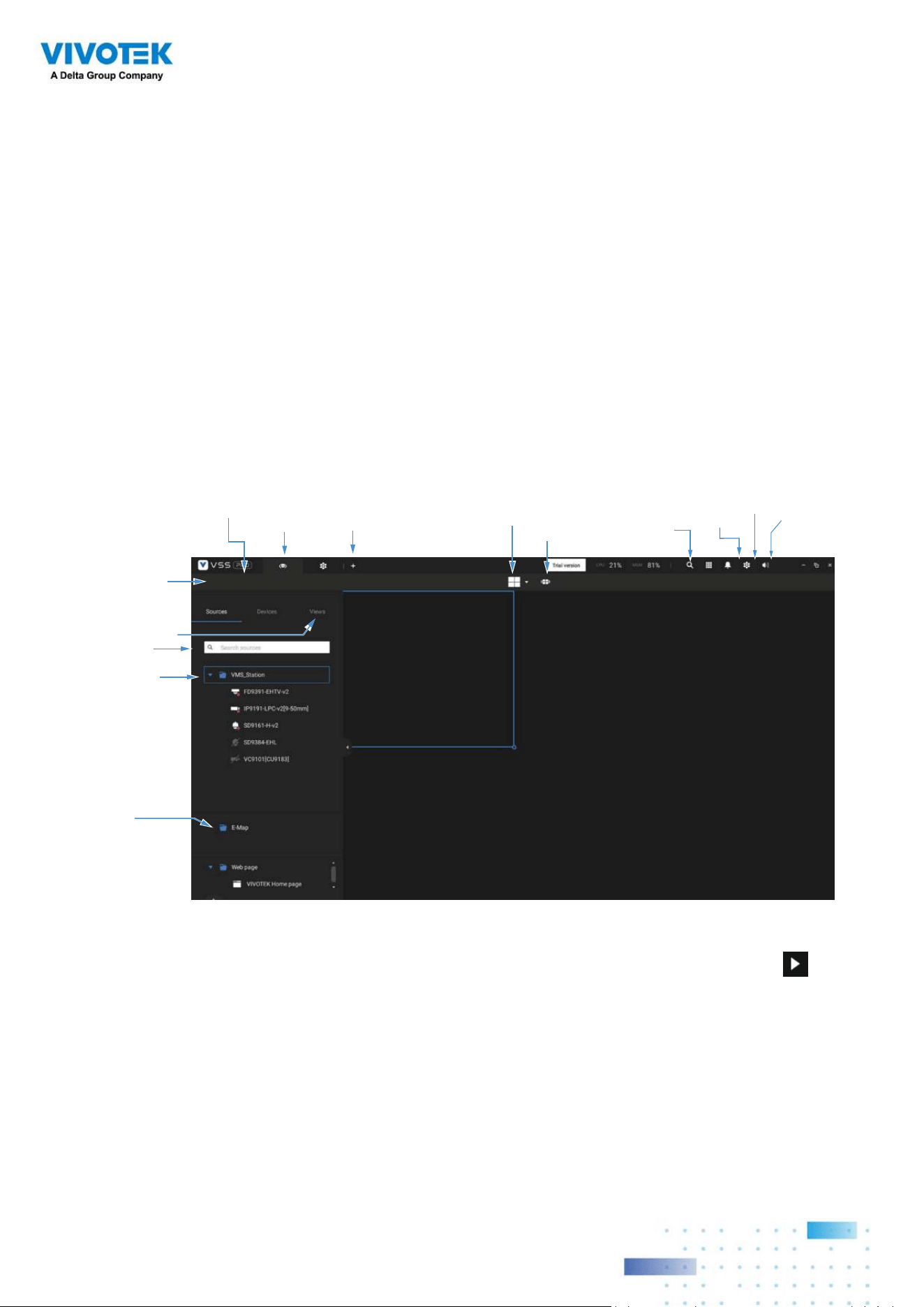
The basic screen elements of VSS live view, playback, and search pane are shown below:
Live view
LiveView
Layout
Tabs
Camera tour
Hide Pane
Bu�on
View
View Cell
Device Tree
Search
View
configura�on
Se�ngs
System
resources
Applica�ons
Alarm
list/search
New
Tab
E-Map
Playback is evoked when a view cell is selected, and you click the Playback button on
the upper right of the view cell.
1212
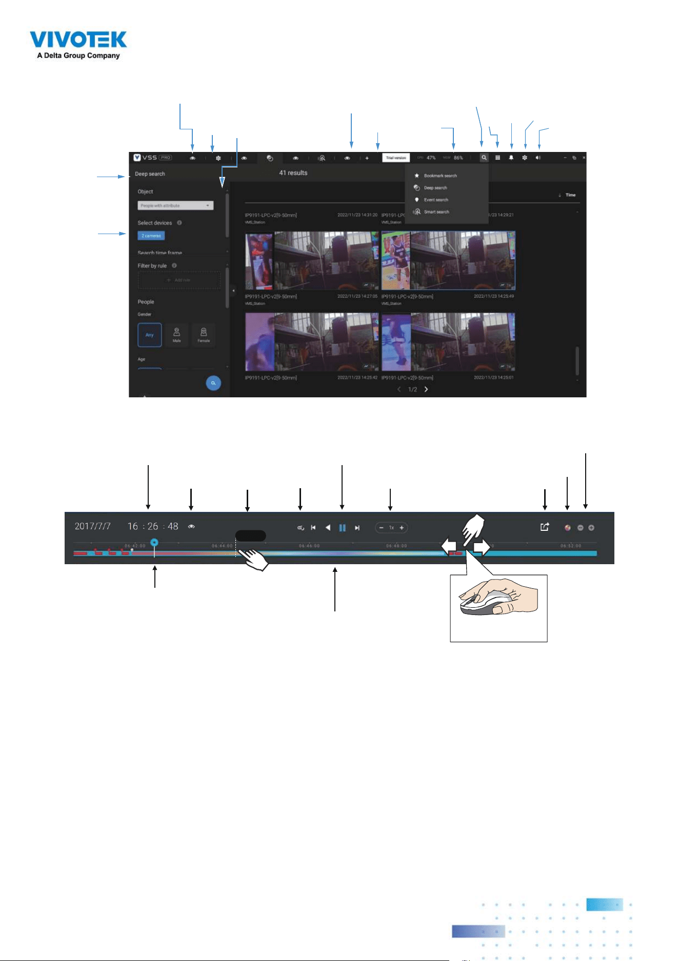
Search Panel
Playback Control
Search pane
LiveView
Layout
Tabs
View
Search
Camera tour
Se�ngs
System
resources
Applica�ons
Alarm
list
Volume
Search
Histogram
Adjustment
Export
Speed Control
Playback Timeline & Histogram
Playhead
Synchronous
Playback Control Buon
Time Search
Events
Highlights
06:44:23
Mouse-over
indicator
Return to Live
Drag to move along
meline
1313
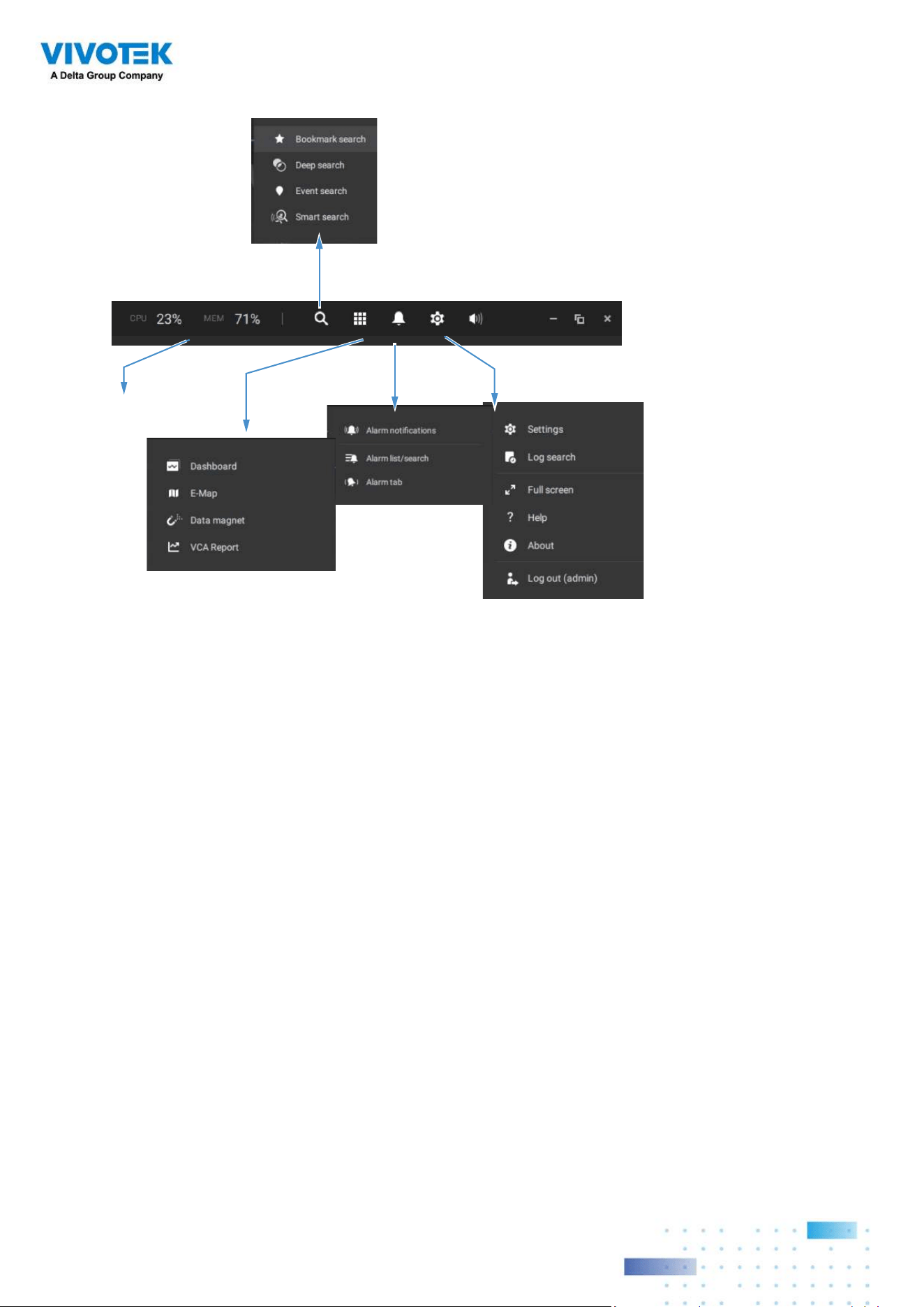
Top Tool Bar
Se�ngs
Applica�ons
Alarm
System
Resources
Search
1414
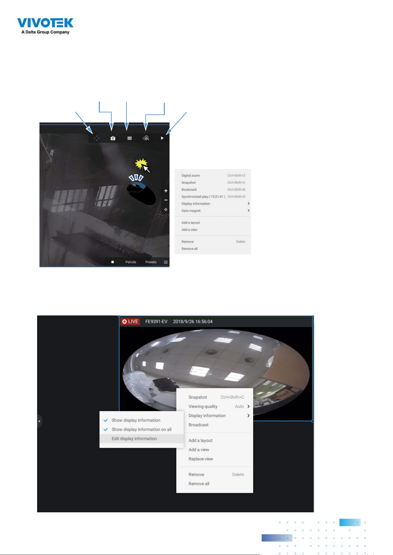
View cell control
Some controls and functions are available when a view cell is selected or via the right-click
menus.
Smart
Search II
Snapshot
Thumbnail
Search
Camera-specific
Replay
Text overlay
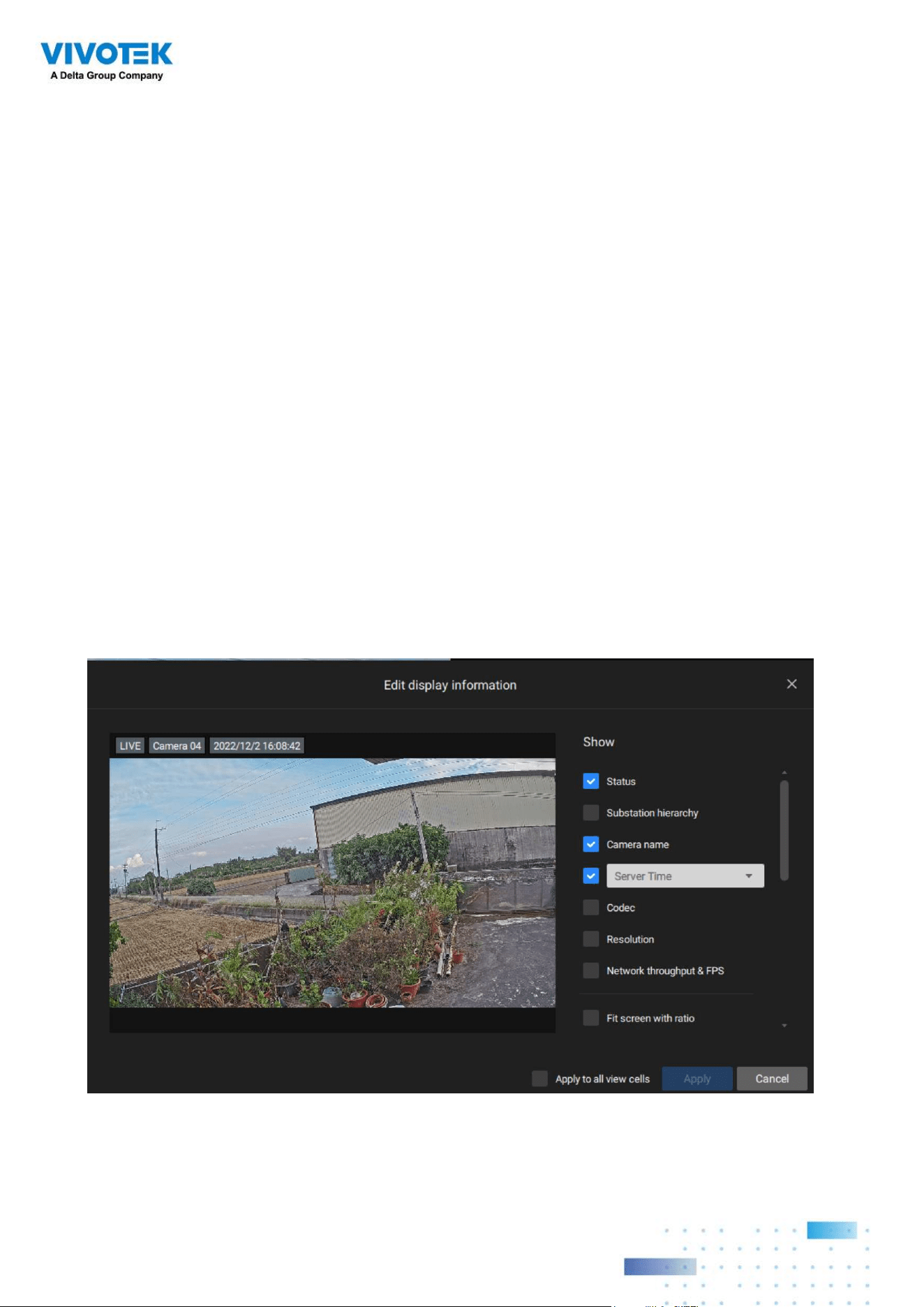
Single-click to select a view cell, right-click and select Display information. The Edit display
information tab will appear.
1515
Two Way Audio
If your cameras support the Two Way Audio feature and the microphone and audio output to
an amplified speakers have been connected, you can right-click on the camera to display the
Broadcast function. Click on the Microphone icon in the middle to start speaking. Click again
to stop the Two Way Audio.
Note that the Broadcast option only appears when you select a camera that supports the
Two Way Audio feature. Currently the VSS software supports 1 to 1 broadcast.
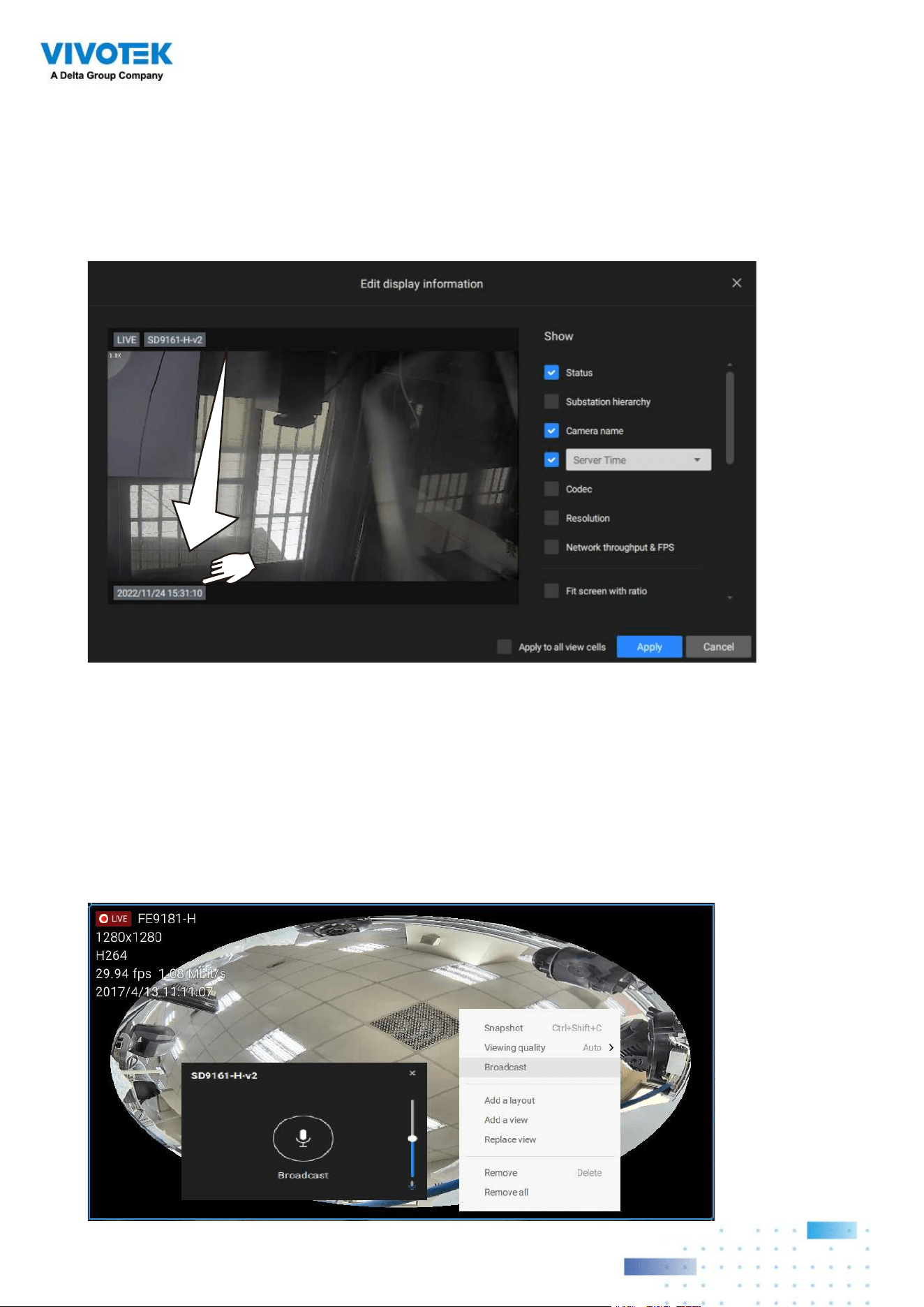
Select the checkboxes to determine what kind of text overlay will display on view cells.
Note that you can place the overlay either on top or at the lower screen. Simply click and
drag an overlay item to a preferred location. When done, click the Apply button.
You can apply your current configuration to all view cells by selecting the Apply to all view
cells checkbox. Note that you can also display the VCA rules and areas on screen.
1616
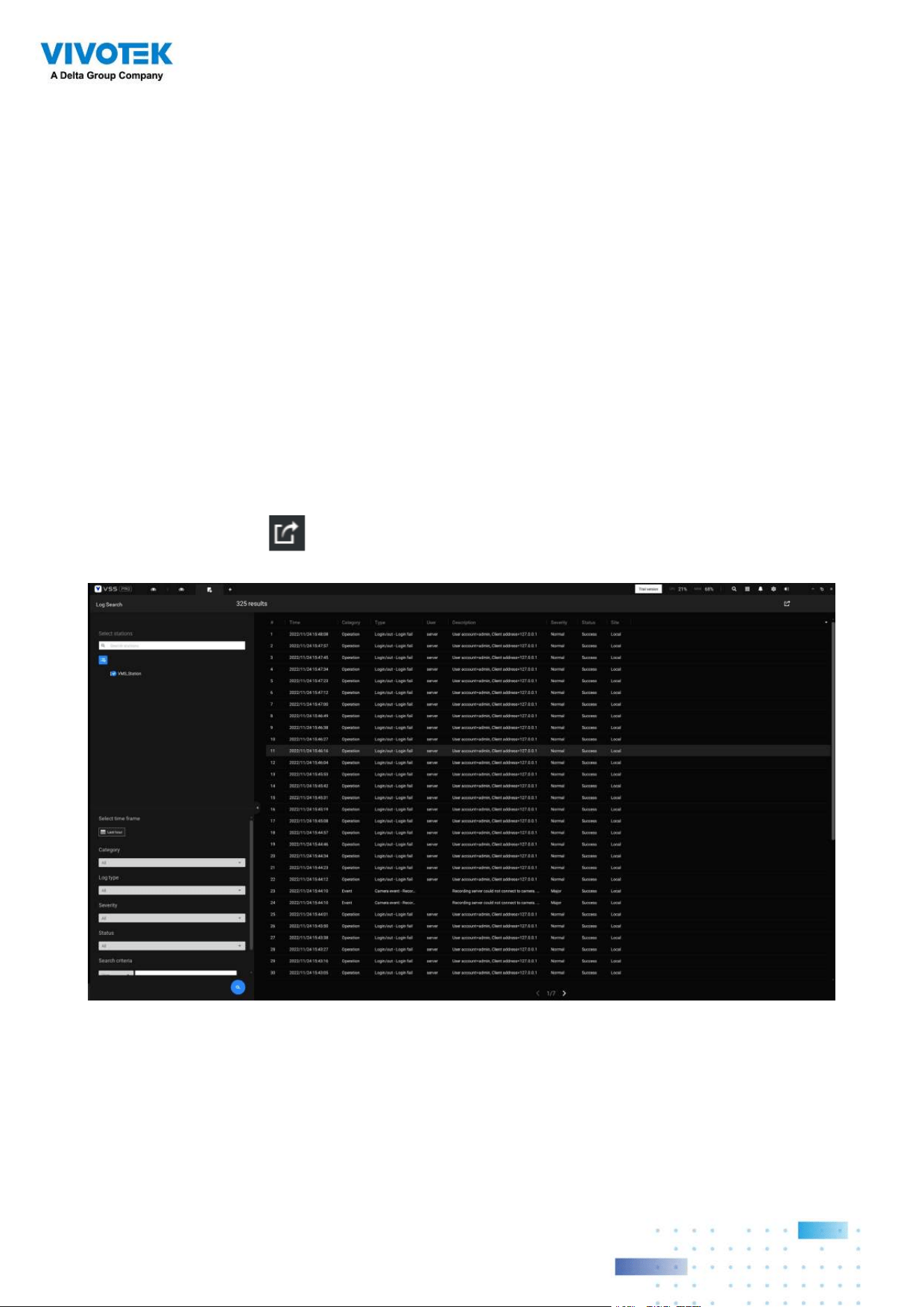
Log Search
System logs can be found via the tool bar tab. All system events will be listed in the Log
search panel. If you have multiple server, substations, select a server. You can search
specific events by the event types (All triggers, camera, system/station, external devices), or
by the time of occurrence using the calendar tool.
Use the Export button to export the system log as an individual log file.
Full Screen
The full screen function maximizes the display of view cells, concealing all other tool bar or
navigation panels. To return to the normal view, press the ESC key on keyboard.
1717
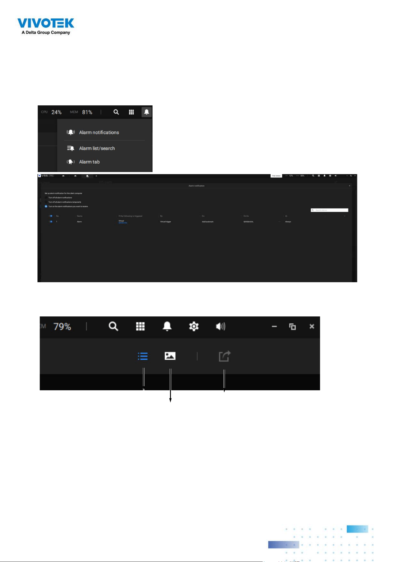
Alarm list
The Alarm list is accessed from the top tool bar. The Alarm list provides easy access to all
triggered alarms, such as tampering alarms, alarms reported by VCA analytics, external
devices connected via a camera's DI pin, etc.
The Alarm list can be displayed in either the List view or Thumbnail view.
List view
Thumbnail view
Export
1818
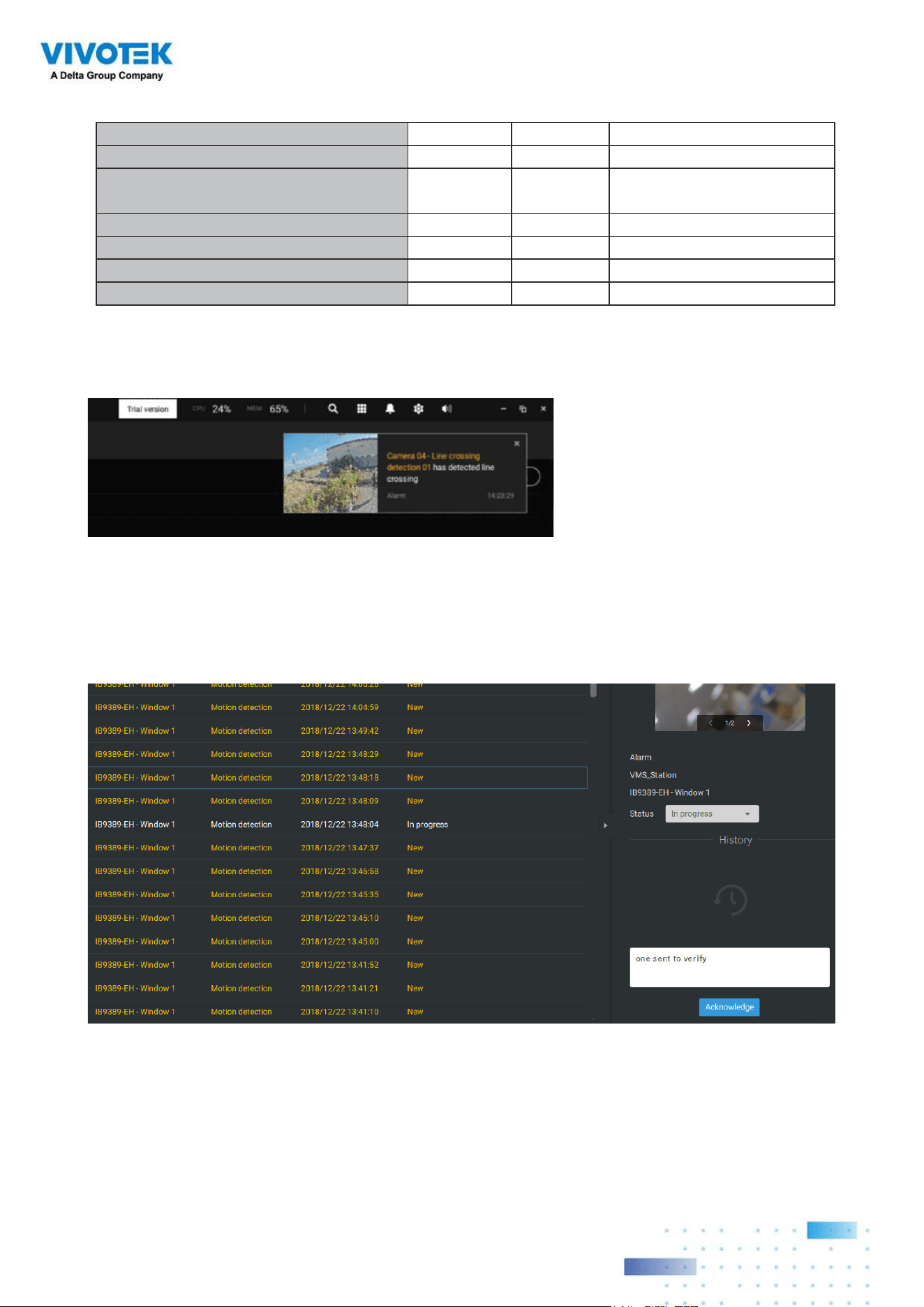
On the Alarm list, you can double-click to select a triggered alarm. A related snapshot and
configuration panel will appear. An operator can select the Status menu to change the event
management status. The configurable statuses can be:
1.
New: An event that has not been handled.
2.
In progress: Select to indicate that the event is being handled, e.g., a security personnel
has been sent to verify the cause of the event.
3.
False alarm: Used to indicate the event has been verified as a false alarm.
4.
Close: A closed case event will be erased from the event list.
When done with designating event status, click the
Acknowledegment button.
Below is an example of a Thumbnail view.
1919
The Alarm list also supports Hot keys.
Alarm list window
Mute the current alarm Ctrl m
Designate the selected alarms as
false alarms
Ctrl f
Select all alarms Ctrl a
Select one or multiple alarms Ctrl left mouse button
Select multiple alarms Shift left mouse button
Select different alarms Up/Down/Left/Right
When an alarm is muted, a message will prompt asking for how long the alarm will be
muted. Enter a number, and the alarm will disappear from the list temporarily.
When an alarm is designated as a false alarm, it is immediately removed from the list.
When an alarm is designated as In progress, you can add a comment on the current
condition, and click Acknowledge to change its status.
2020
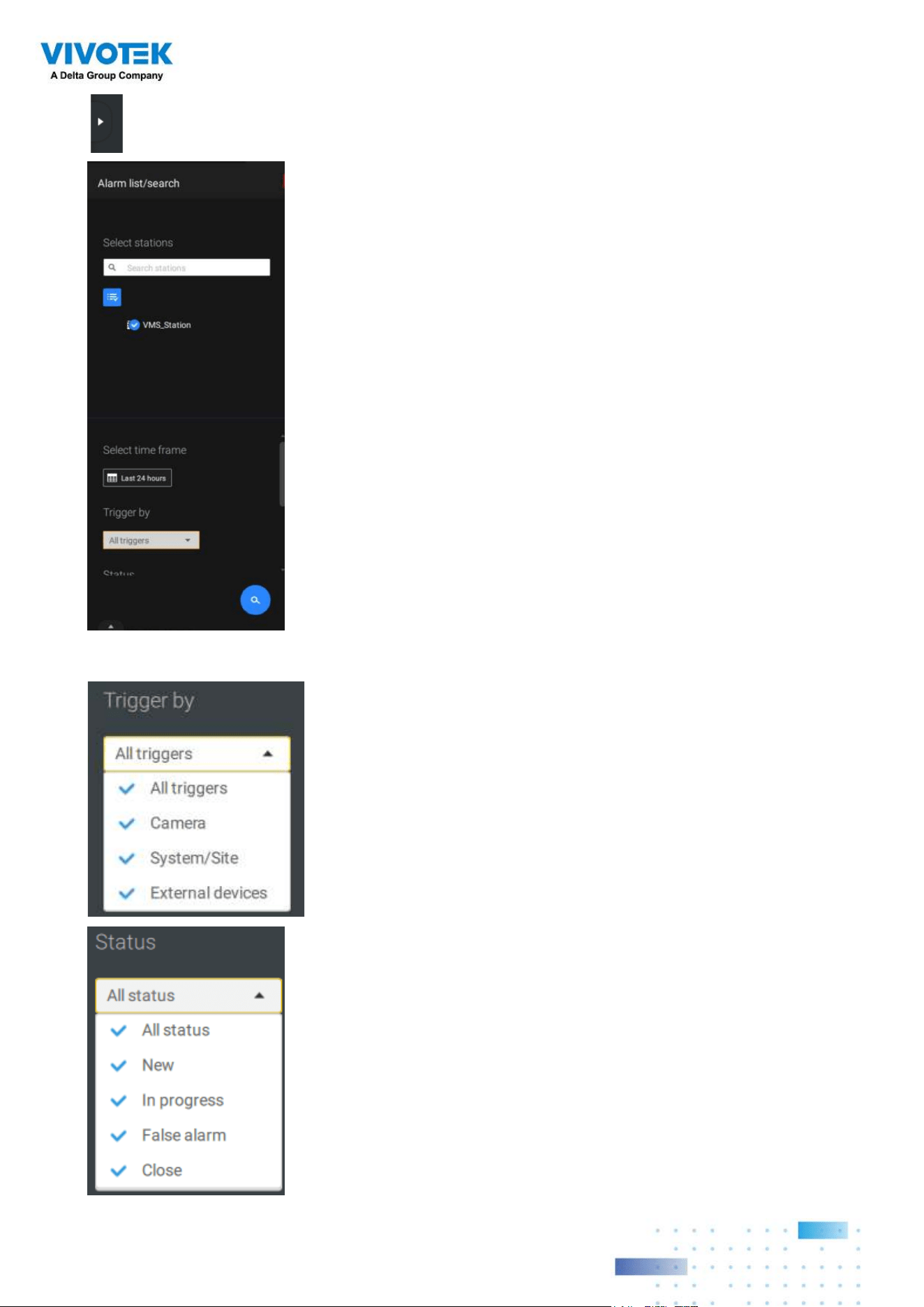
To find alarms of specific types, time of occurrences, and alarm
status, click the side tab to reveal the search panel.
You can select the trigger source, e.g., when you need to see
camera alarms only.
You can check to see alarms of a specific status. For example,
you can select to search for the "In progress" alarms only.
2121
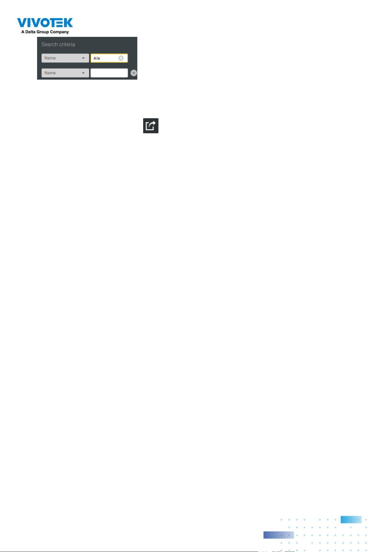
You can use the Export button to export a full list of all triggered events into a CSV file.
The event type, receiving station, triggering device, time of occurrence, and event status will
all be listed. You can also export alarm-triggered videos.
You can also add a comment for an event by entering the description in the comment entry
field.
You can enter one or multiple keywords as the search criteria.
For example, if you have an alarm named as "Alarm3-
sidewalk," use the name as the keyword to search for the
related alarms.
2222
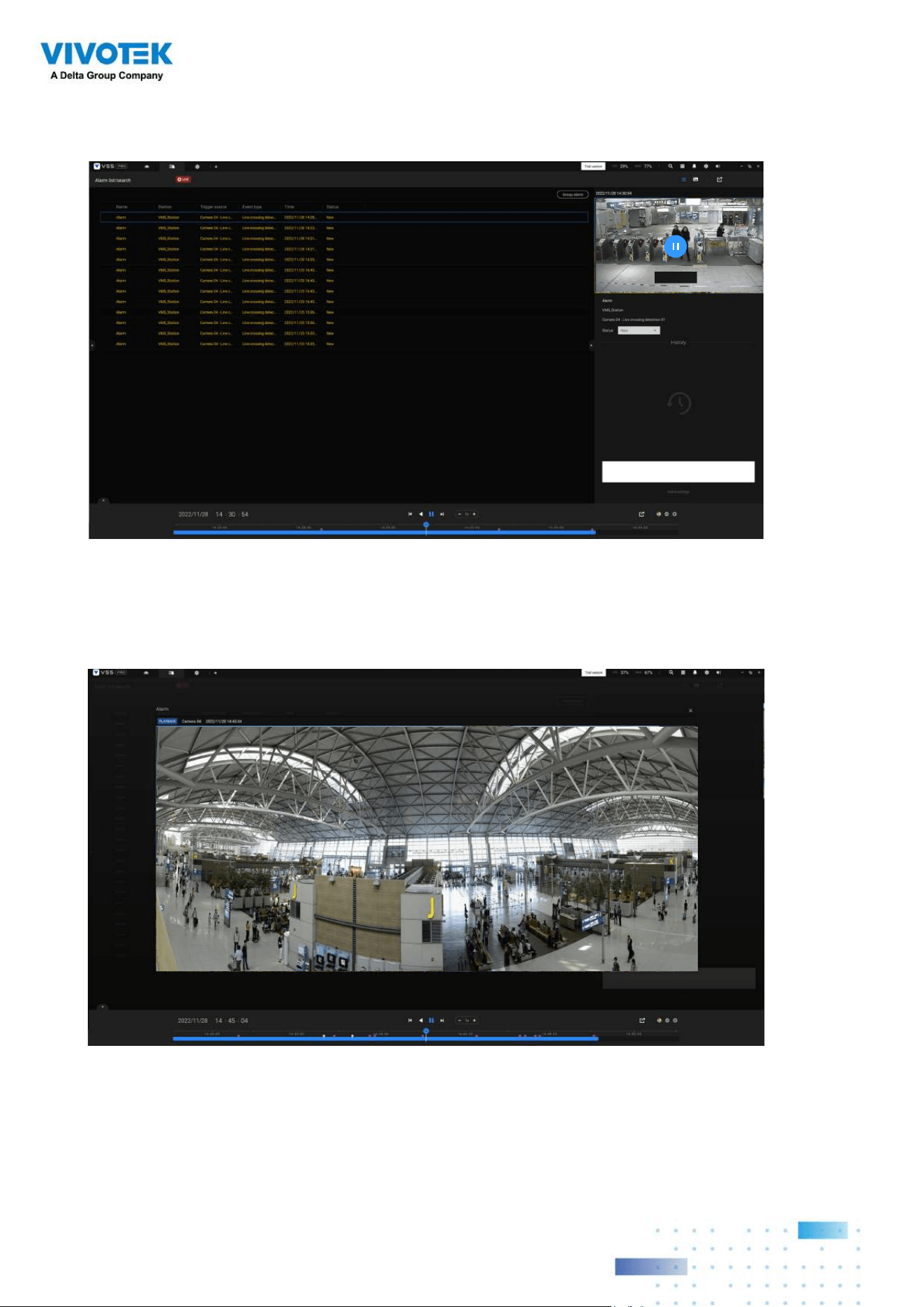
To review the alarm-related video, click to select an alarm, double-click to playback. The
Playback window will appear on the upper right of the screen.
< 1/2 >
Double-click on the small playback screen again to bring it to the full view. The playback
control, time line, export, and alarm tags will be available on screen.
2323
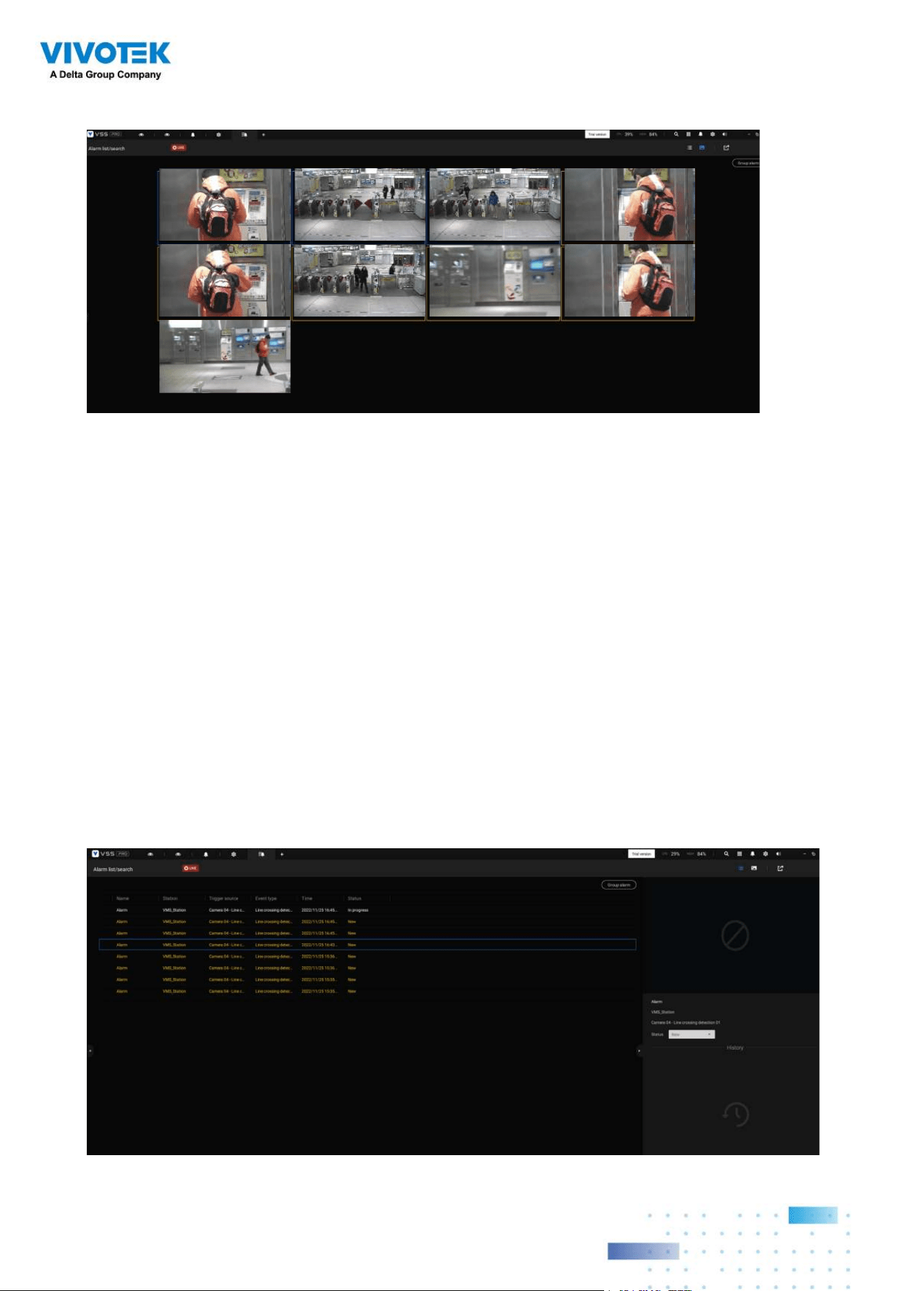
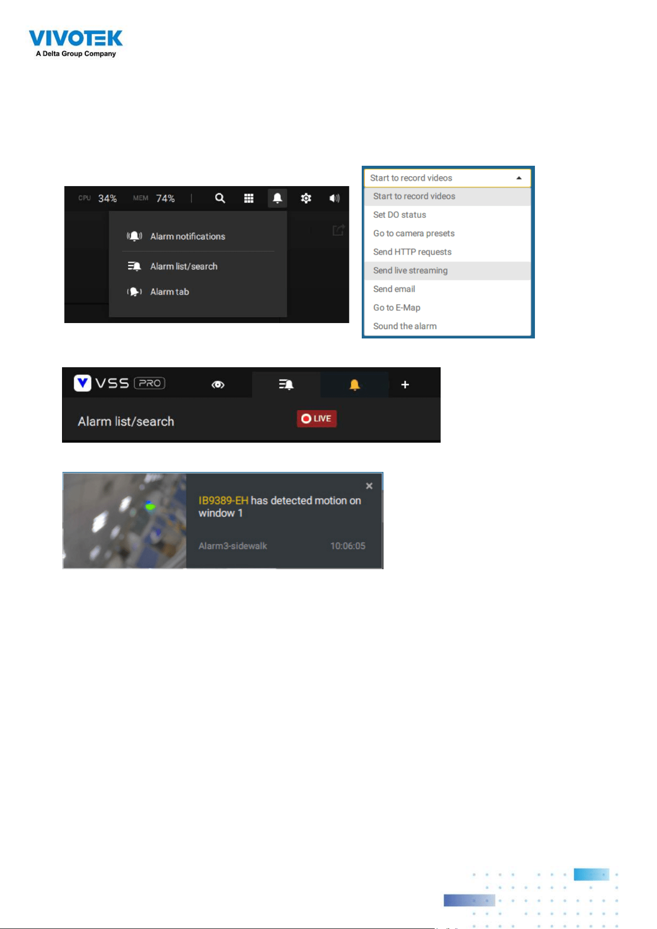
Alarm tab
The Alarm tab is an automated streaming window displaying live videos brought by the
triggered alarms. If you configure an alarm action as "Send live streaming," the alarm
streaming will be displayed in this window. Note that this window does not display other
types of alarms.
When a live streaming is sent by an alarm, an orange ringing bell icon will display.
An alarm prompt will also display on the screen.
You can click on the ringing bell icon to open the Alarm tab window. The alarm-trigged
streamings will be available on screen.

2424
Hot Keys
Open online document F1
Close current tab Ctrl (Win) /
Command (MacOS)
W
Open new Live / Playback tab Ctrl (Win) /
Command (MacOS)
T
Full screen
Ctrl (Win) /
Command (MacOS)
Shift F
Exit full screen Ctrl (Win) /
Command (MacOS)
Shift F
Exit full screen Esc
View cell
Select view cell Arrow keys
Digital zoom Ctrl (Win) /
Command (MacOS)
Shift Z
Snapshot Ctrl (Win) /
Command (MacOS)
Shift C
Instant bookmark Ctrl (Win) /
Command (MacOS)
Shift B
Remove camera from cell Del
Move to preset position Ctrl (Win) /
Command (MacOS)
Digits (1,2,3,...)
PTZ model up, down, left, right Arrow keys
Save current layout as a
customized layout
Ctrl (Win) /
Command (MacOS)
S
Undo layout modication Ctrl (Win) /
Command (MacOS)
Z
Redo layout modication Ctrl (Win) /
Command (MacOS)
Y
Timeline
Sync Playback mode Ctrl (Win) /
Command (MacOS)
Shift S
Pause (Play/Rewind) Space
Play Ctrl (Win) /
Command (MacOS)
Arrow right
Rewind Ctrl (Win) /
Command (MacOS)
Arrow left
Speed up Ctrl (Win) /
Command (MacOS)
Up
Speed down Ctrl (Win) /
Command (MacOS)
Down
Next frame Shift Arrow right
Previous frame Shift Arrow left
Reset speed to 1x Ctrl (Win) /
Command (MacOS)
1 (one)

2525
Bookmark search
Select more bookmarks Ctrl (Win) /
Command (MacOS)
Click
Select more bookmarks Shift Click
Back to bookmark page Esc
Next bookmark Arrow right
Previous bookmark Arrow left
Thumbnail search
Select thumbnail Arrow keys
Play a selected thumnail Enter
Back to Thumbnail page Esc
Next Thumbnail Arrow right
Previous Thumbnail Arrow left
Emap Setup
- Google map
Remove selected GPS Del
DI/DO Device Settings
Remove selected external I/O
device
Del
SMTP Settings
Remove selected SMTP
server
Del
Camera Management
Rename selected camera F2
Rename selected folder F2
Remove selected camera
from system
Del
Stations Management
Rename selected station F2
Remove selected station from
system
Del
Users Settings
Remove selected user Del
Schedule Settings
Remove scheduled time frame Del
Smart search II
- Conguration page
Delete detection range Esc

2626
Data Magnet
Move selected row Up / Down
Show detail of selected row Enter
View management
Rename selected view F2
Delete selected view Del
Alarm management
Delete selected alarm Del
Alarm list window
Mute the current alarm Ctrl (Win) /
Command (MacOS)
m
Designate the selected alarms
as false alarms
Ctrl (Win) /
Command (MacOS)
f
Select all alarms Ctrl (Win) /
Command (MacOS)
a
Select one or multiple alarms Ctrl (Win) /
Command (MacOS)
left mouse button
Select multiple alarms Shift left mouse button
Select different alarms Up/Down/Left/Right
2727
View Cell Elements
On a view cell, the control elements are different with different types of network cameras.
3 major types are listed below with applicable screen elements:
1. Fixed cameras:
Snapshot - Thumbnail search - Smart
search - Replay.
2. Fisheye cameras:
Fisheye display mode - Snapshot -
Thumbnail search - Smart search - Replay.
Zoom In
Zoom Out
The Auto pan function applies only to the Regional views. Select a regional view, and
click the Auto pan button. The Regional view will pan from side to side to cover more
viewable regions. If a fisheye is mounted on wall, a regional view with auto pan can
cover a panoramic view region.
2828
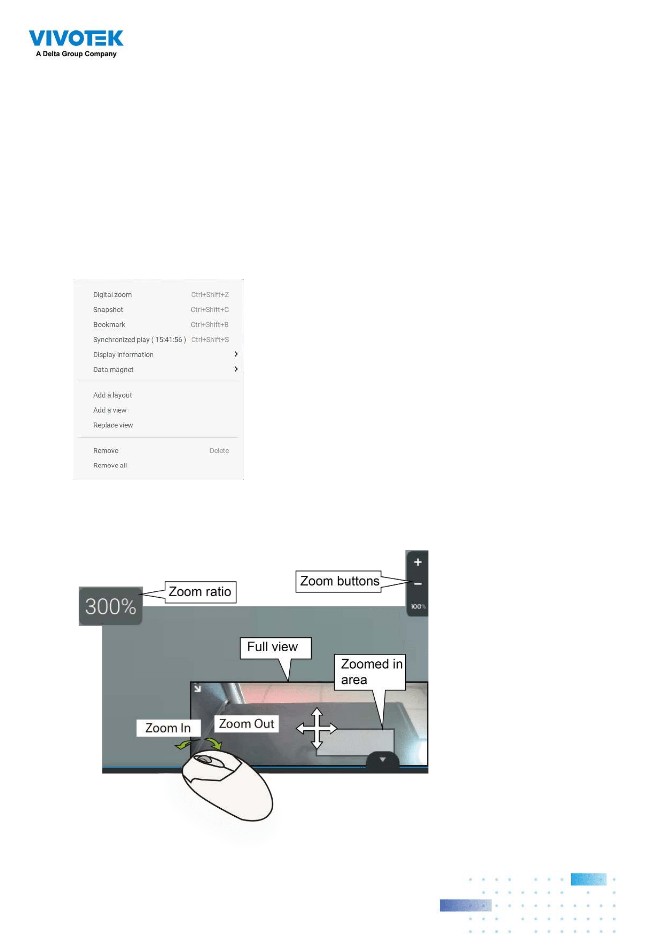
You can use the mouse wheel to zoom in or zoom out on the screen. The zoom ratio is
shown on screen for half a second.
When PTZ is enabled, the zoom buttons and a home button are displayed on the right hand
side of the view cell.
For more information about Snapshot, Thumbnail search, and the Replay functions, please
refer to their specific help pages.
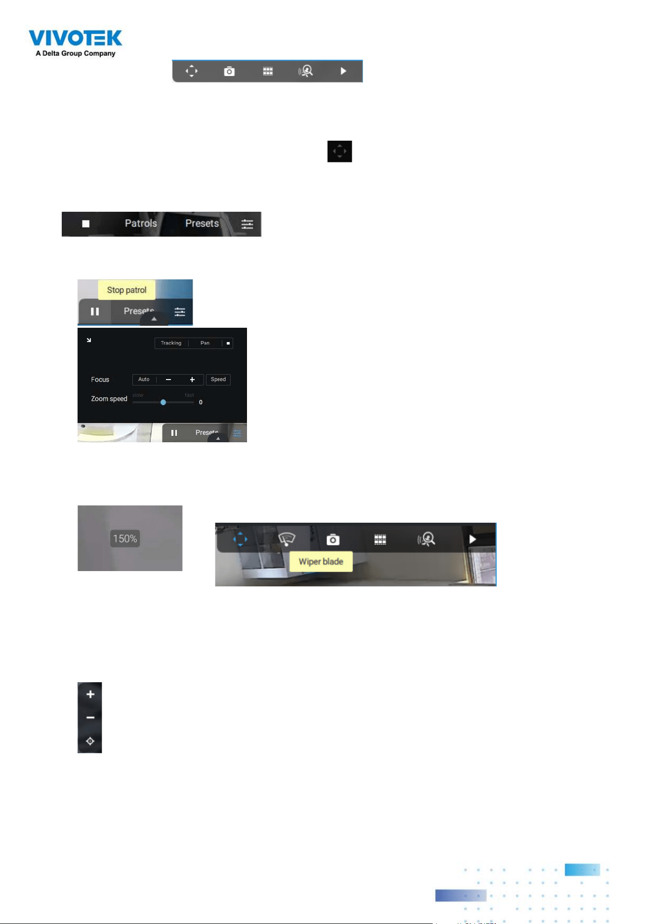
3. PTZ cameras:
PTZ - Snapshot - Thumbnail search -
Smart search - Replay. For information about PTZ control, refer to the discussion on PTZ
on page 71.
To exert PTZ control, first click on this button to enable PTZ control.
When PTZ control is enabled, the following controls are available on screen:
Click Patrols or Presets if these have been configured on the PTZ camera. You will need to
open a web console to the camera to configure preset positions.
The PTZ settings tab allows you to enable PTZ Tracking and the Pan functions. You can
also adjust the Zoom and Focus speed, or manually adjust the focus. Please refer to the
camera User Manual for more information about these functions.
For speed dome cameras that come with a wiper blade, the wiper blade control button will
be available on the tool bar.
2929
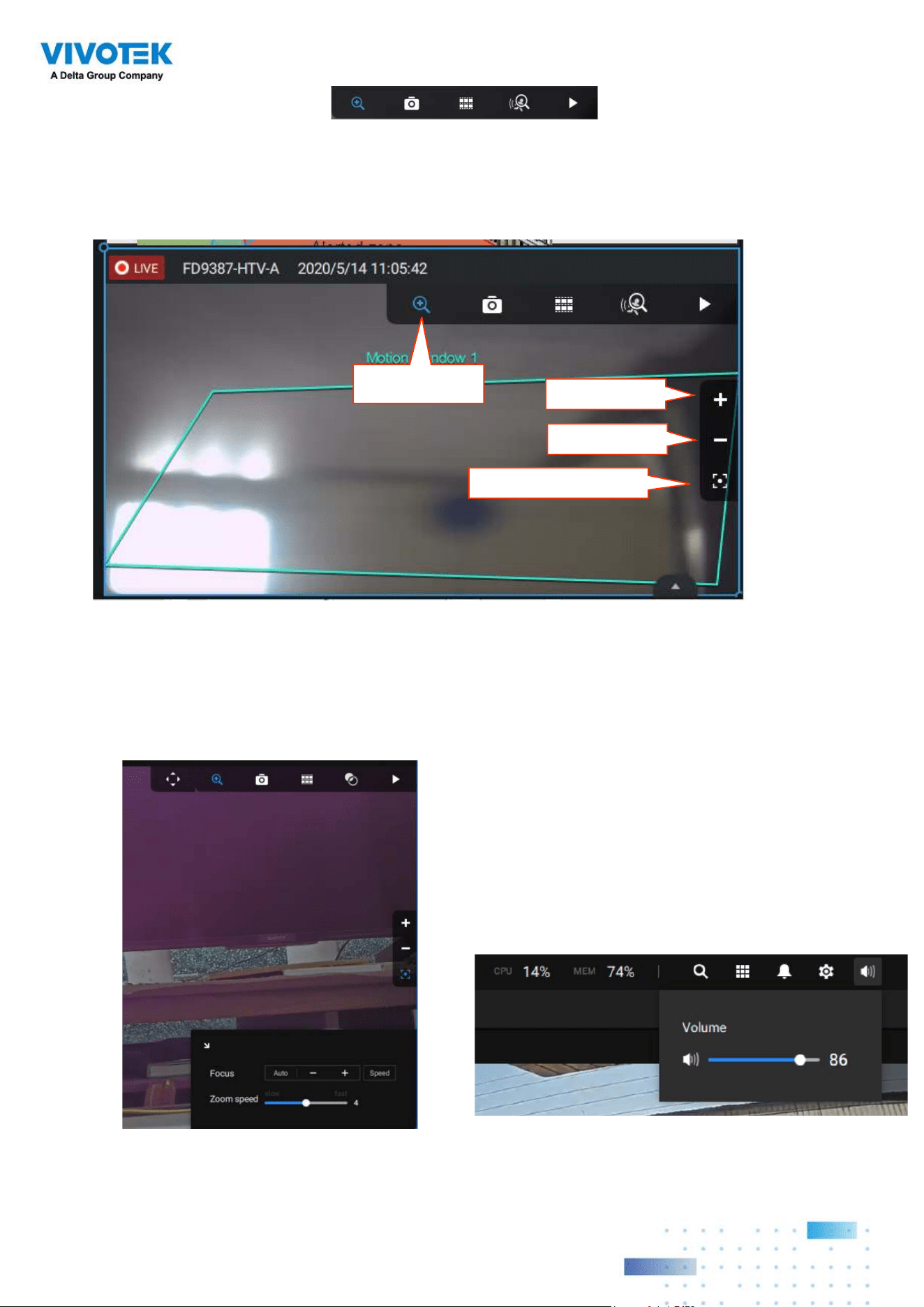
3. Motorized lens cameras:
Enable Optical - Snapshot -
Thumbnail search - Smart search - Replay.
For cameras that come with motorized zoom lens, click on the Enable Optical button. You
can zoom in or zoom out on the scene.
Click on the Focus adjustment button to bring out the focus panel. If you find the image is
out of focus, you can use the +, -, or Auto buttons to regain the best image focus.
You can use the Auto scan function to let the camera automatically find the best focus.
The process may take up to 20 seconds.
Enable Optical
Zoom in
Zoom out
Focus adjustment
Audio
For a view cell housing a camera with
an audio input, you can tune its volume
using the slide bar on the tab panel.
3030
VSS Server
Network Cameras
Stand-alone site
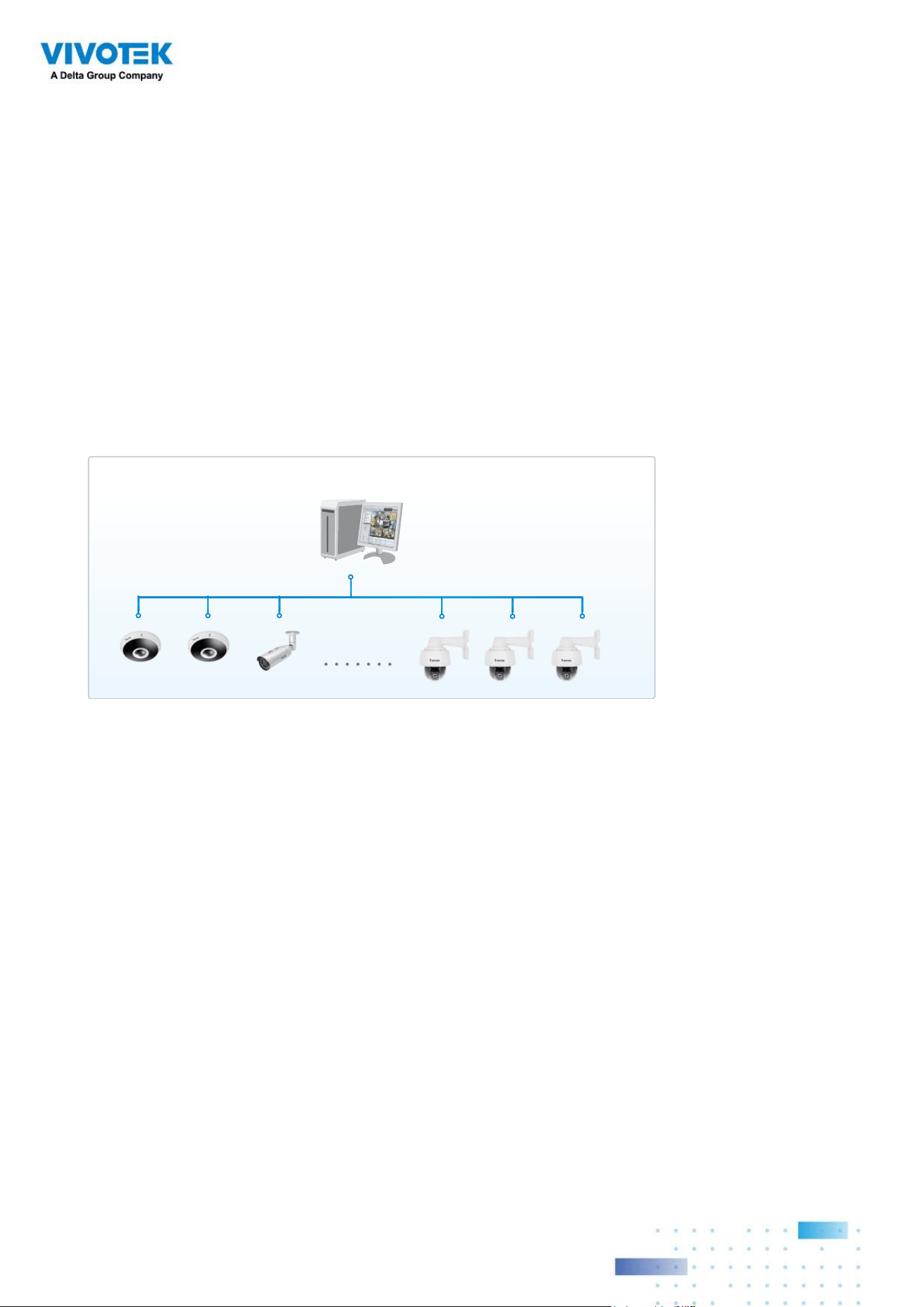
Server and Client
Components
VSS Server provides a centralized management site for video recording. Users can login
and modify the server's configuration, edit the server's recording storage, configure
schedules and many other functions. You can browse the recorded video database and
video clips related to specific events on the server.
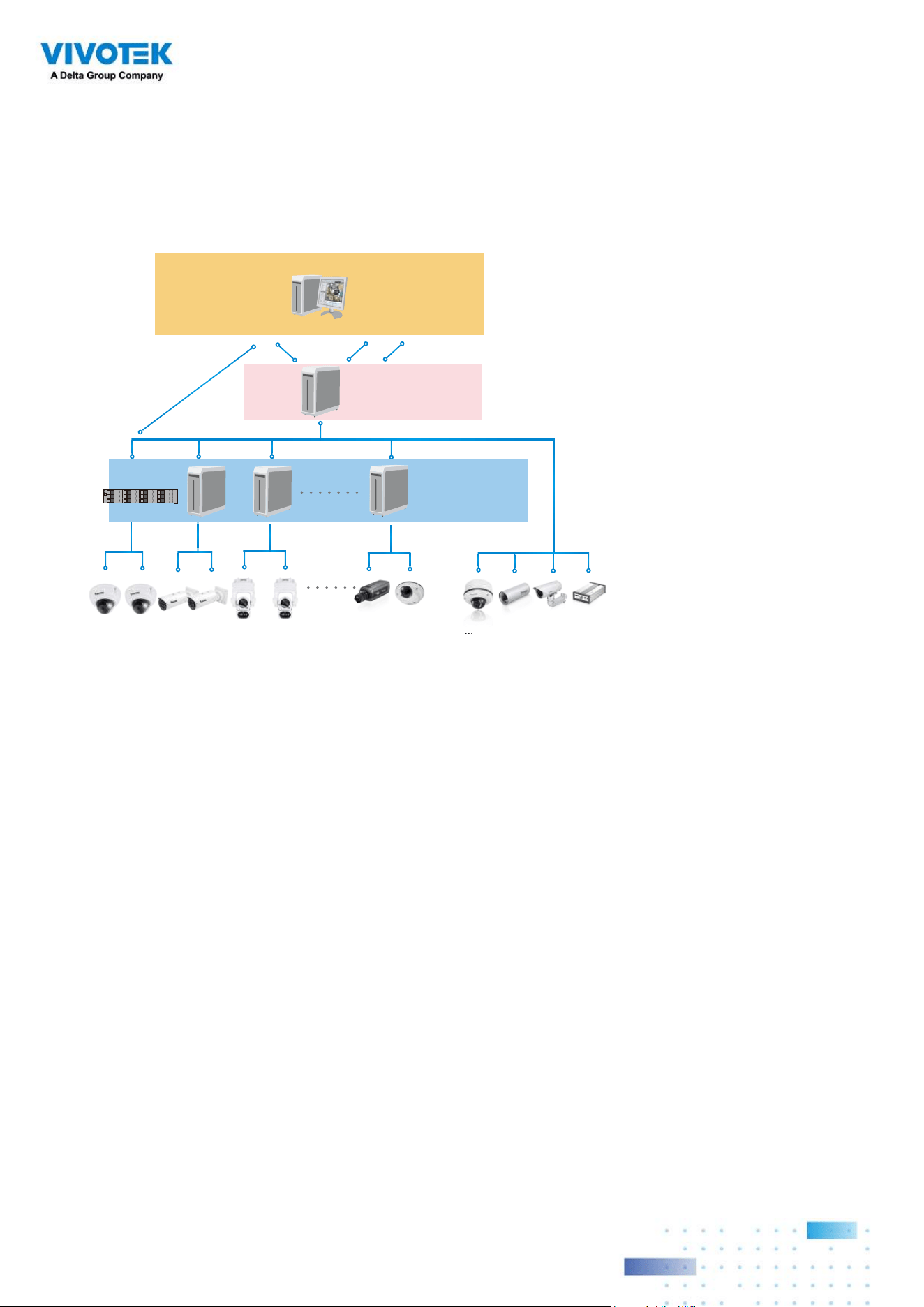
Local Server Structure
For users who manage large-scale surveillance deployments, please plan the hierarchical
structure first. Then you can start to add cameras to each station and connect these
sub-stations to the root station. The whole hierarchical management system is thus
constructed. VIVOTEK's NVR stations can also be included as sub-stations. The Logical
Tree view becomes the default.
3131
Please refer to the Stations page for how to enlist VSS sub-stations.
Unlimited No. of Network Cameras , Video Servers...
Remote Server Structure
Login
Login
Client VSS
(Root station)
VSS CMS Server
VSS Server
(Sub-stations)
NVR
Multiple Server Applications
A host with the VSS installed is recognized as a stand-alone station. All the functions can
be simultaneously performed on one single station.
3232
Chapter 2 Starting Up
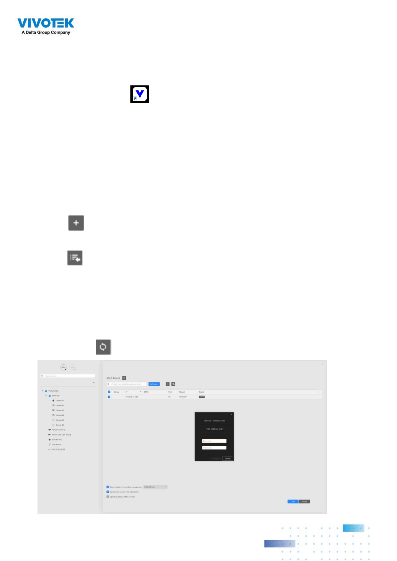
Double-click the VSS icon on the desktop to start the VSS main page.
When started the first time, the server automaticallly polls the local network for reacheable
network cameras. For cameras that come with pre-configured User Name and Passwords,
the server prompts for entering credentials for the access to cameras. Check out the
cameras' MAC addresses to identify the cameras.
The cameras found within the network will be listed. If the need should arise, you can use
the Search panel on top to locate specific cameras using their IP, MAC, Port, Model name,
or brand name (ONVIF/VIVOTEK).
Use the
Add device button to manually add a camera with its known IP or domain
name.
Use the
Import Device List button to recruit cameras in a previously-saved device list
(CSV files).
Use the Authorize button if the camera found in the Search panel needs credentials.
When search is done, delete the alpha-numeric characters in the search field to return to
the device list.
Use the Refresh
button to search the local network again.
3333
2-1. Selecting Devices
Use the checkboxes in front of the listed devices to determine which devices will
be recruited to your configuration. By default, all cameras are selected. When the
selection is done, click on the Next button at the lower right screen.
If any of the selected devices requires credentials, the authorization window will prompt.
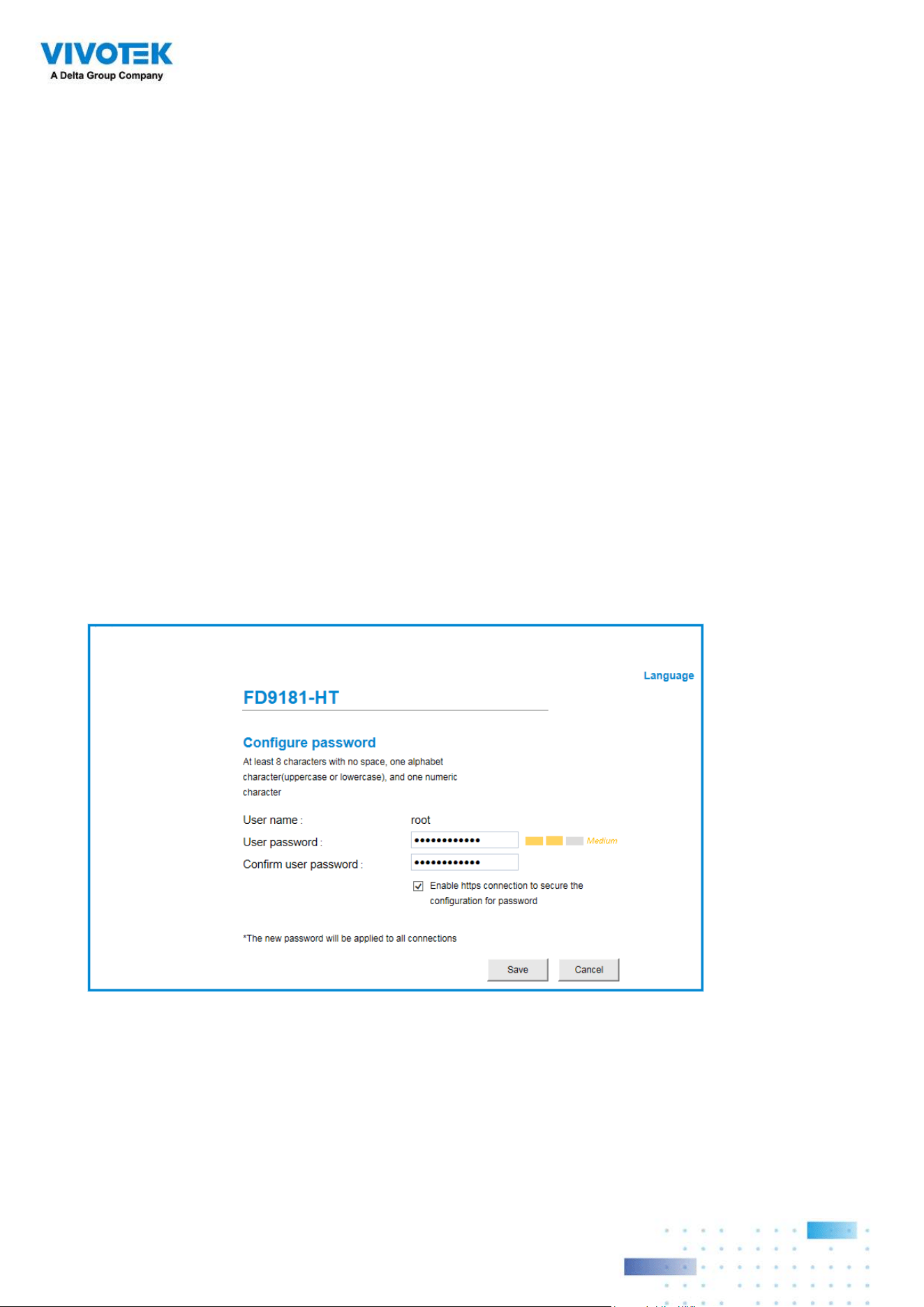
NOTE:
For cameras that come without a password protection, you should open the
Shepherd utility to locate and open a web console, and configure a password for
protecting the access to the camera. If a brand new camera (with no password) is
selected for your VSS configuration, it will join your configuration without the password
protection.
3434
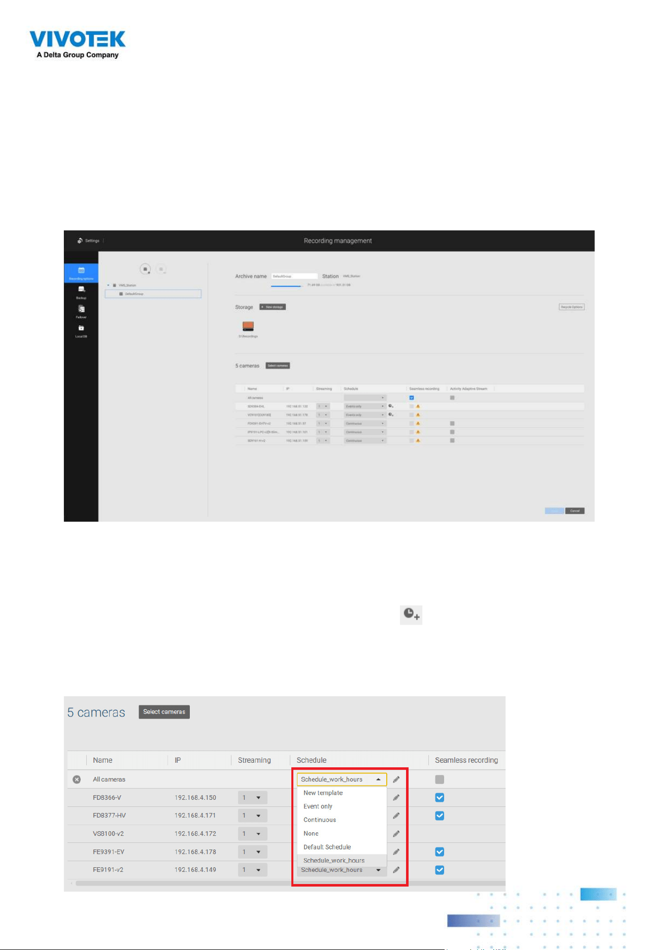
2-2. Recording Options
Click Settings > Recording > Recording options. The Recording options window will
prompt.
You can configure recording schedules or select the storage options, including the
configuration of an external NAS storage.
Click on the Schedule column on the Camera list for a recording option: Continuous
recordings, Events only, None, or Default Schedule, or New template. You can apply a
schedule template for all cameras or configure individual schedules for different cameras.
When using the Event-triggered recording, a pre-event and post-event time can be
configured. An Edit pane is available by clicking the Edit button.
You can manually create a recording template using the New template option. When done,
each configured template will be listed below.
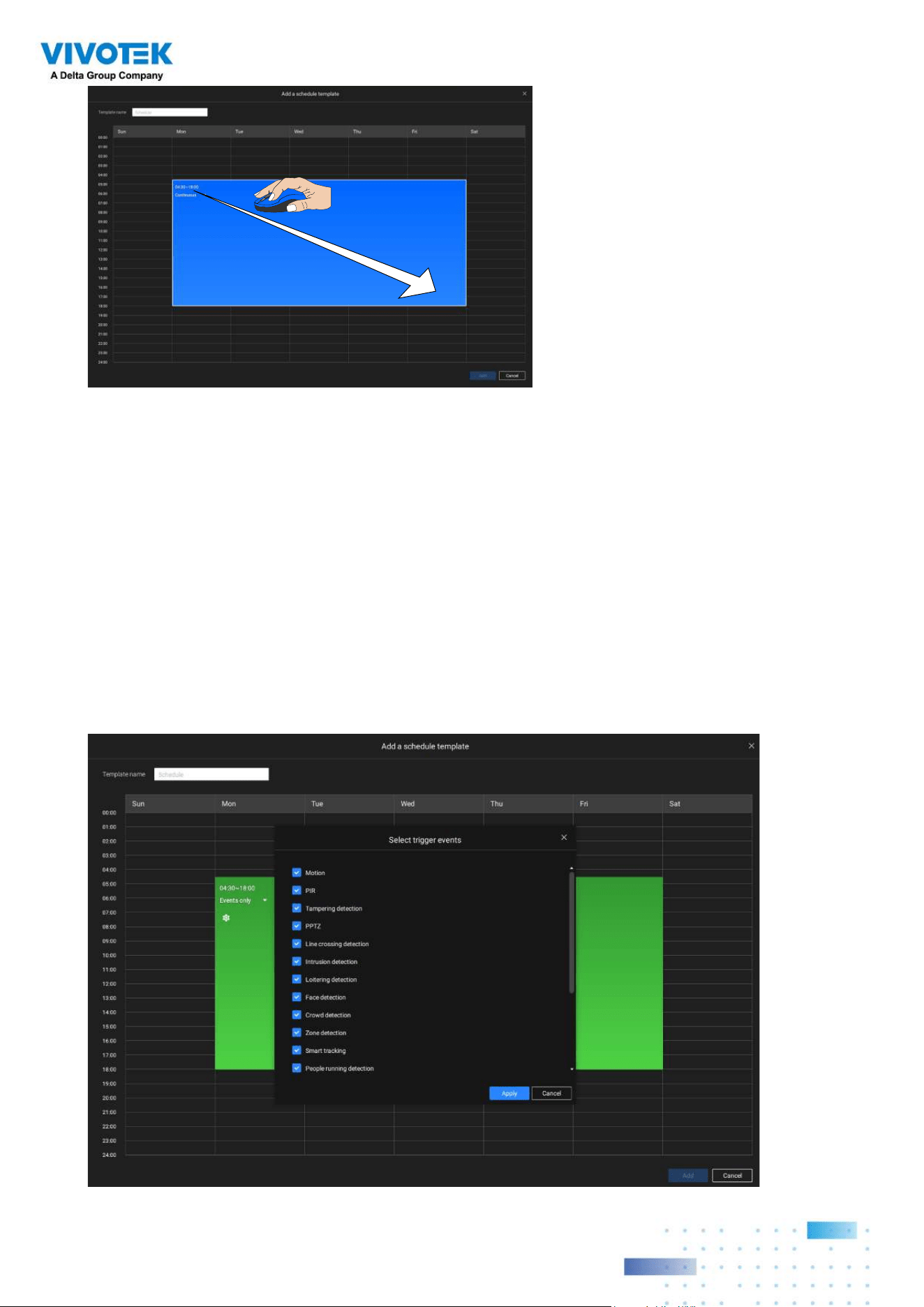
3535
Click and hold down on the time cells, and drag the mouse to include the time span of your
preferrence. The minimum selectable unit is half an hour. You can select separate and
multiple time spans on the template.
Enter a name for the template, and click Add to save your template.
Event types can be selected when
The same configuration window apply to both the Schedule template and the customize
schedule windows.
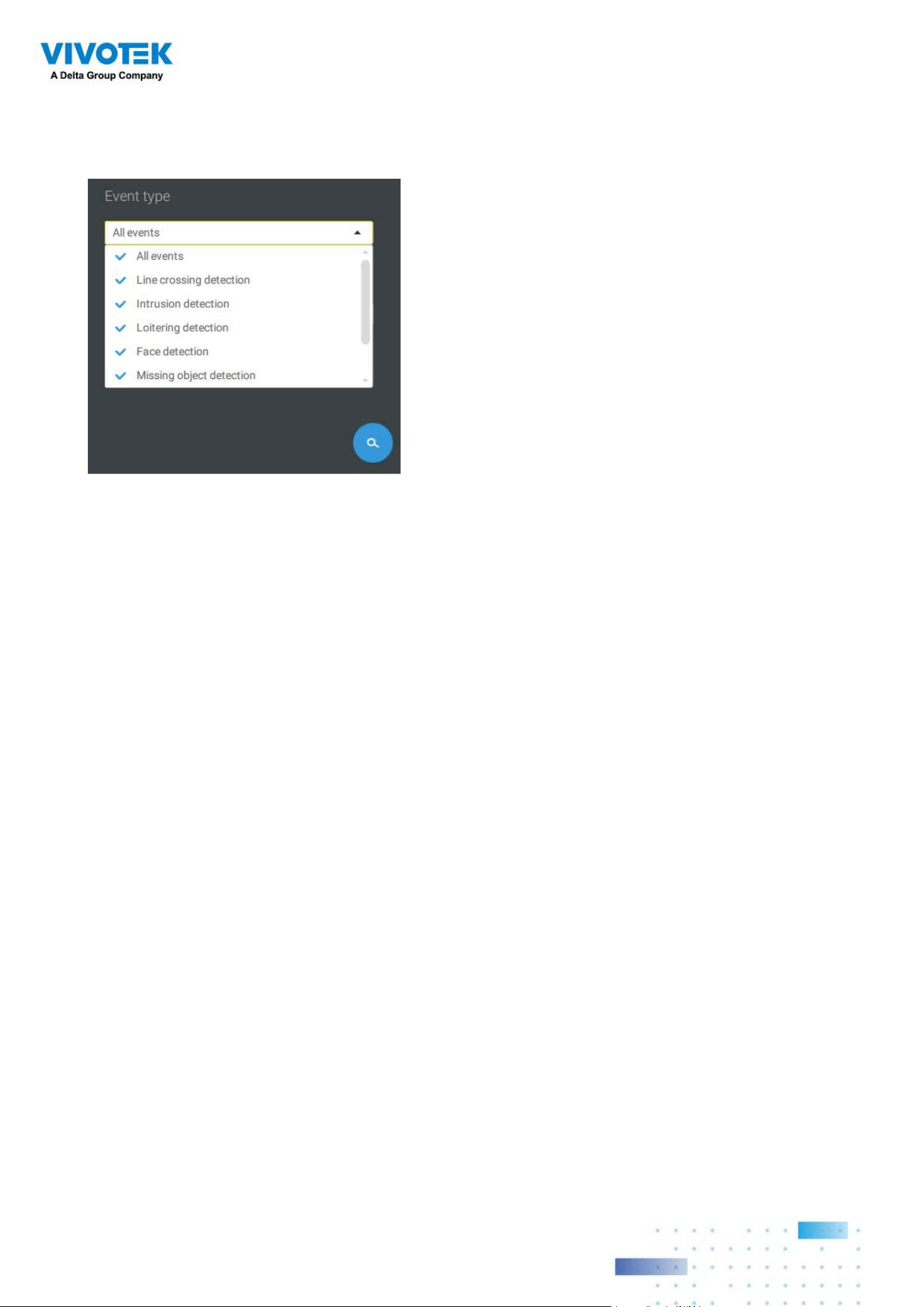
If the Events only option is selected for the new template, you can determine what kinds of
events will trigger the recording. Use the pull-down menu to select Events only.
3636
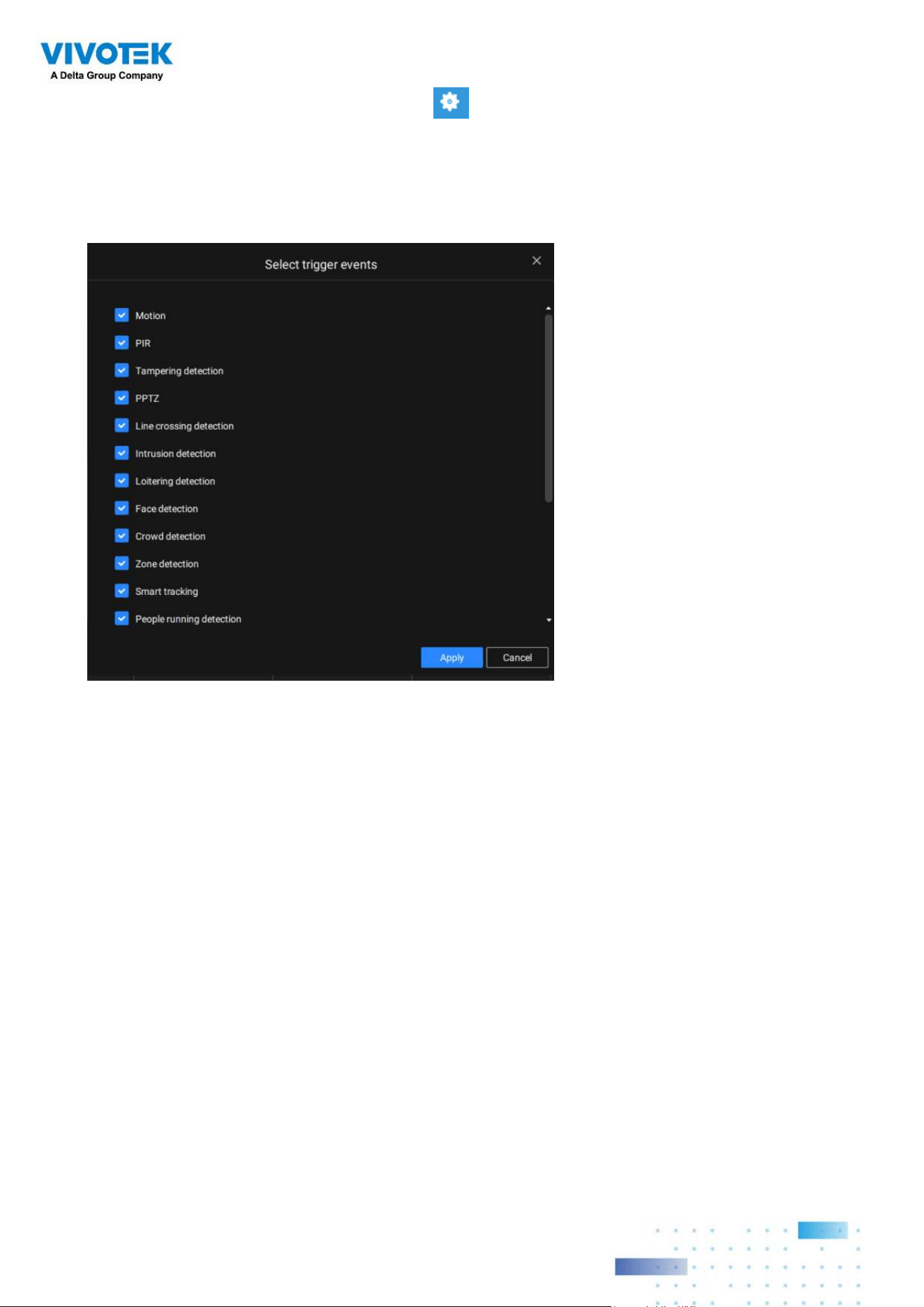
When Events only is selected, click on the
Settings button to proceed.
The applicable event types will be listed. Select the types of event triggers that you prefer.
Click Apply to leave this page. By deault, all applicable event triggers will be selected.
3737
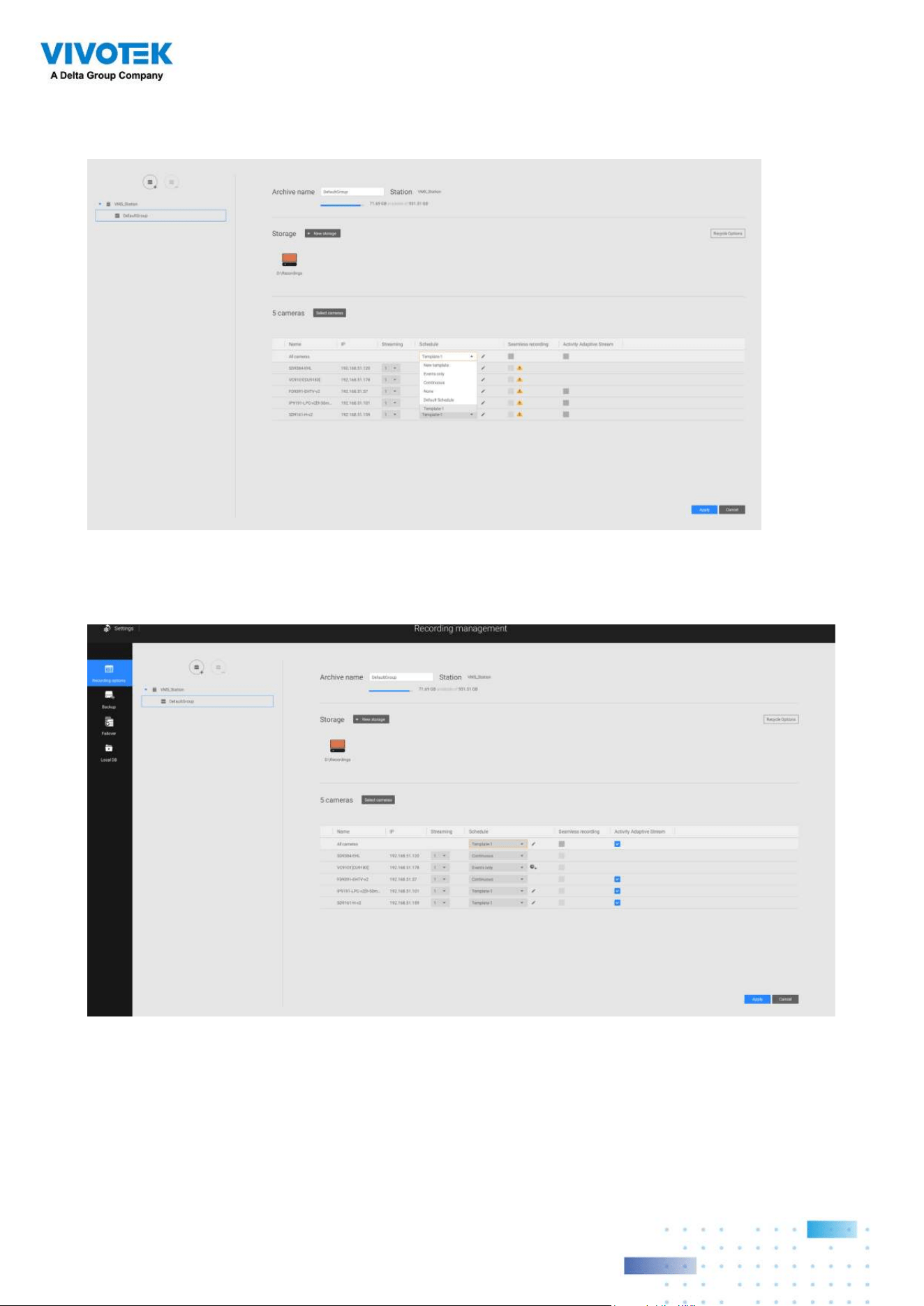
Back on the Recording options page, select the new template as a scheduling option. Use
the menu on the top to select a scheduling template for all cameras.
Make sure a Schedule mode is selected when you leave this configuration step.
3838
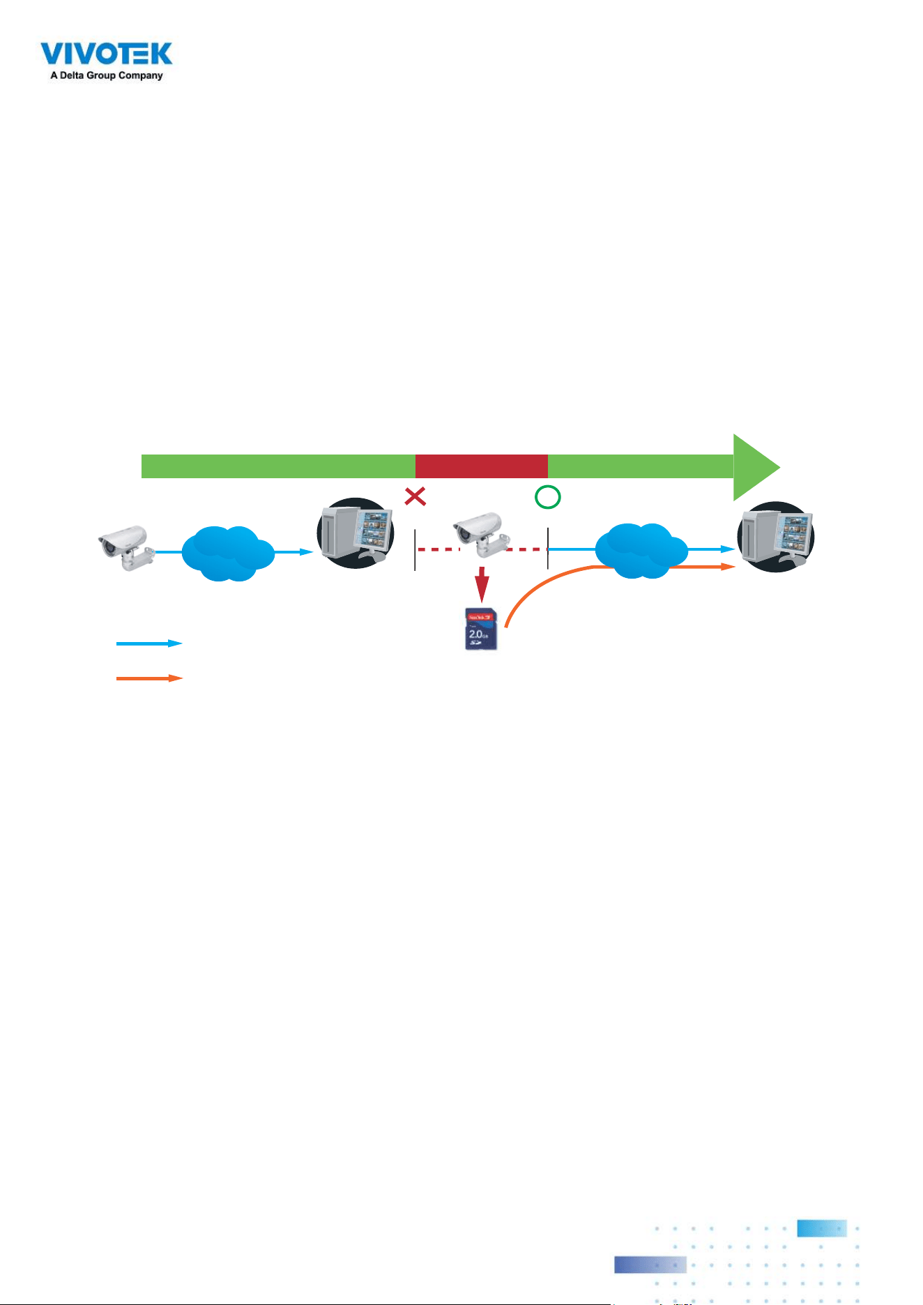
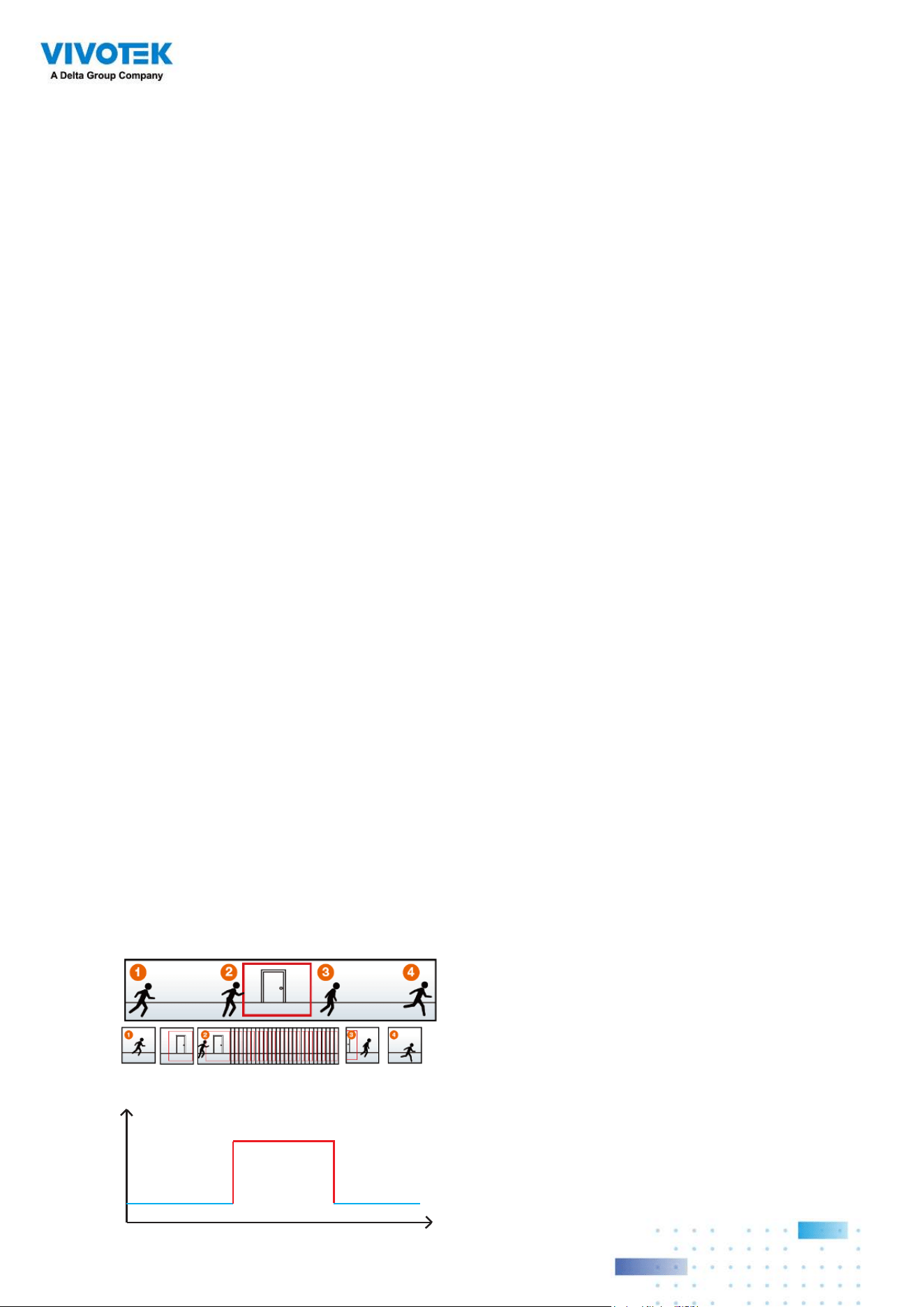
Seamless Recording
Seamless Recording safeguards critical videos in the occurences of network
disconnection. In the event of temporary disconnection, video is stored in individual
cameras' SD/SDHC/SDXC card; and once the connection is restored, a VSS server
can automatically resume the recording. More remarkable is that, a VSS server can
simultaneously retrieve the time-tagged videos that were temporarily stored on SD/SDHC/
SDXC cards. For information about the latest firmware/software revisions that support this
feature, please contact your sales representatives or technical support.
Server Station
14:30 14:50
Disconnect Restored
Timeline
LAN/WAN
Server Station
LAN/WAN
1
4
:
3
0
~
1
4
:
5
0
Seamless Recording
SD/SDHC/SDXC
Normal recording
Retrieval
The video data retrieved from SD/SDHC/SDXC card also include event-triggered recordings
such as pre- or post-event footages, if events were detected during the network outage.

3939
The Seamless Recording feature is enabled when inserting, updating, or batch inserting
cameras in the Camera Management window. The firmware/hardware compatibility of this
feature is automatically detected, i.e., this feature is not available when a non-compliant
camera is attached. If a compatible camera is attached, a checkbox will be available as
shown below.
If a camera comes without an SD card, the SD card presence is detected with a warning
message.
4040
Activity Adaptive Stream
■
Activity Adaptive Stream: (Note that this feature may not be available for some older
models)
This option will activate the frame rate control according to alarm trigger.
The frame control means that when there is a triggered alarm, the frame rate will raise up
to the value you’ve congured on the Video quality page.
If you enable adaptive recording on a camera, only when an event is triggered on a camera
will the server record the full frame rate streaming data; otherwise, it will only request the I
frame data during normal monitoring, thus effectively saves bandwidth and storage space.
The alarm trigger includes: motion detection and DI detection.
On individual cameras, you can congure the following:
■
Pre-event recording and post-event recording
The Network Camera has a buffer that temporarily holds data for a period of time.
Therefore, when an event occurs, the camera can restrieve image frames taken several
seconds ago. Enter a number to define the duration of recording before and after a
trigger is activated.
■
Priority: Select the relative importance of this recording (High, Normal, or Low).
Recording with a higher priority setting will be executed rst.
■
Source: Select a video stream as the recording source.
Time
Bandwidth
Bandwidth
Activity Adaptive Streaming
for Dynamic Frame Rate Control
I frame ---> Full frame rate ---> I frame
Continuous recording
NOTE:
* To enable adaptive recording, please make sure you have configured the trigger sources
such as Motion Detection, DI input, or Manual trigger.
* When there is no alarm trigger:
- JPEG mode: record 1 frame per second.
- H.264 mode: record the I frame only.
* When the I frame period is > 1 second on the Video settings page, firmware will force
decrease the I frame period to 1 second when the Activity Adaptive Recording feature is
enabled.
4141
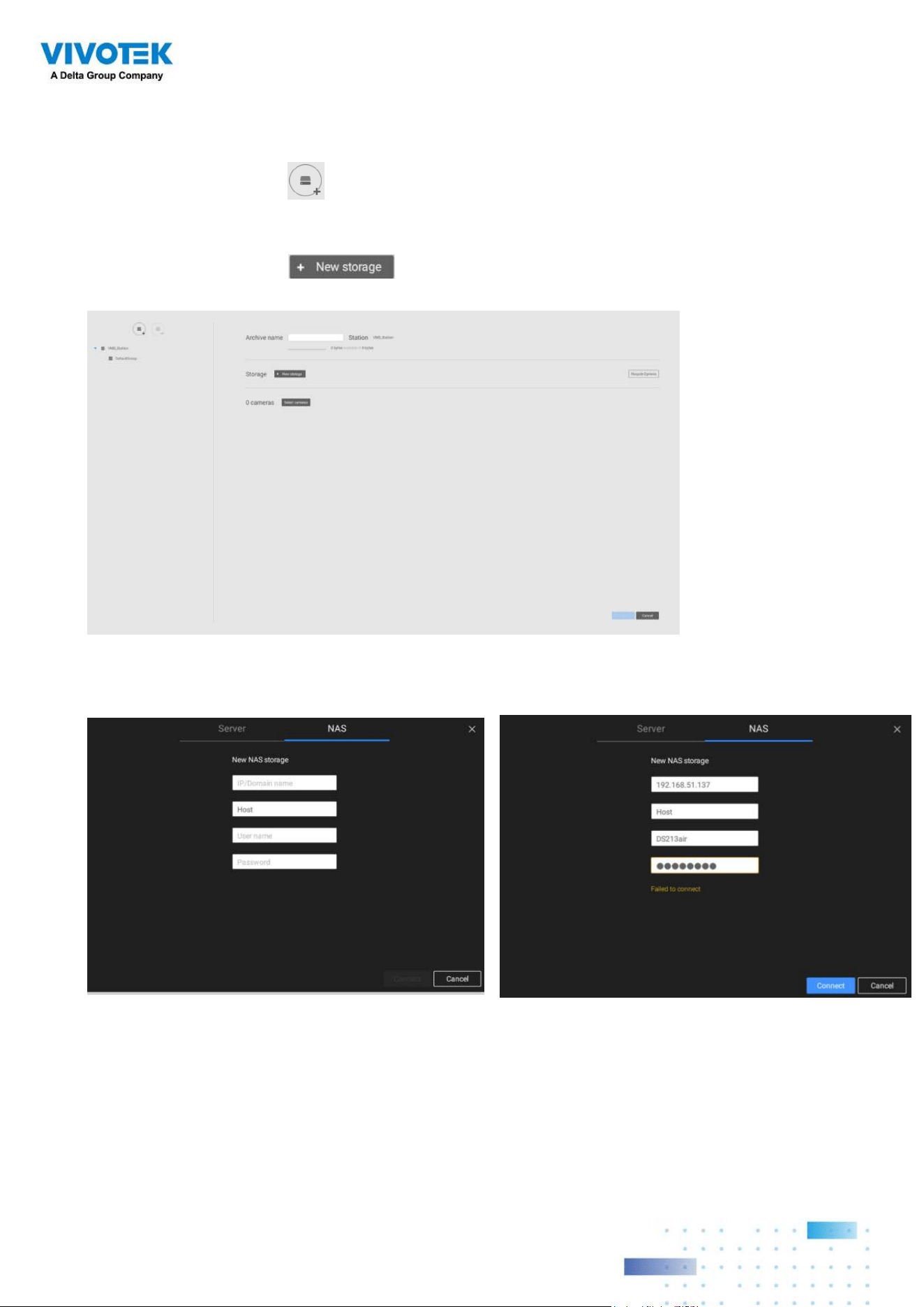
Adding NAS (Network Attached Storage) as a Storage Option
You can also record videos to a networked storage.
1. Click the Add archive
button.
2. Enter a name for the configuration.
3. Click the Add storage
button.
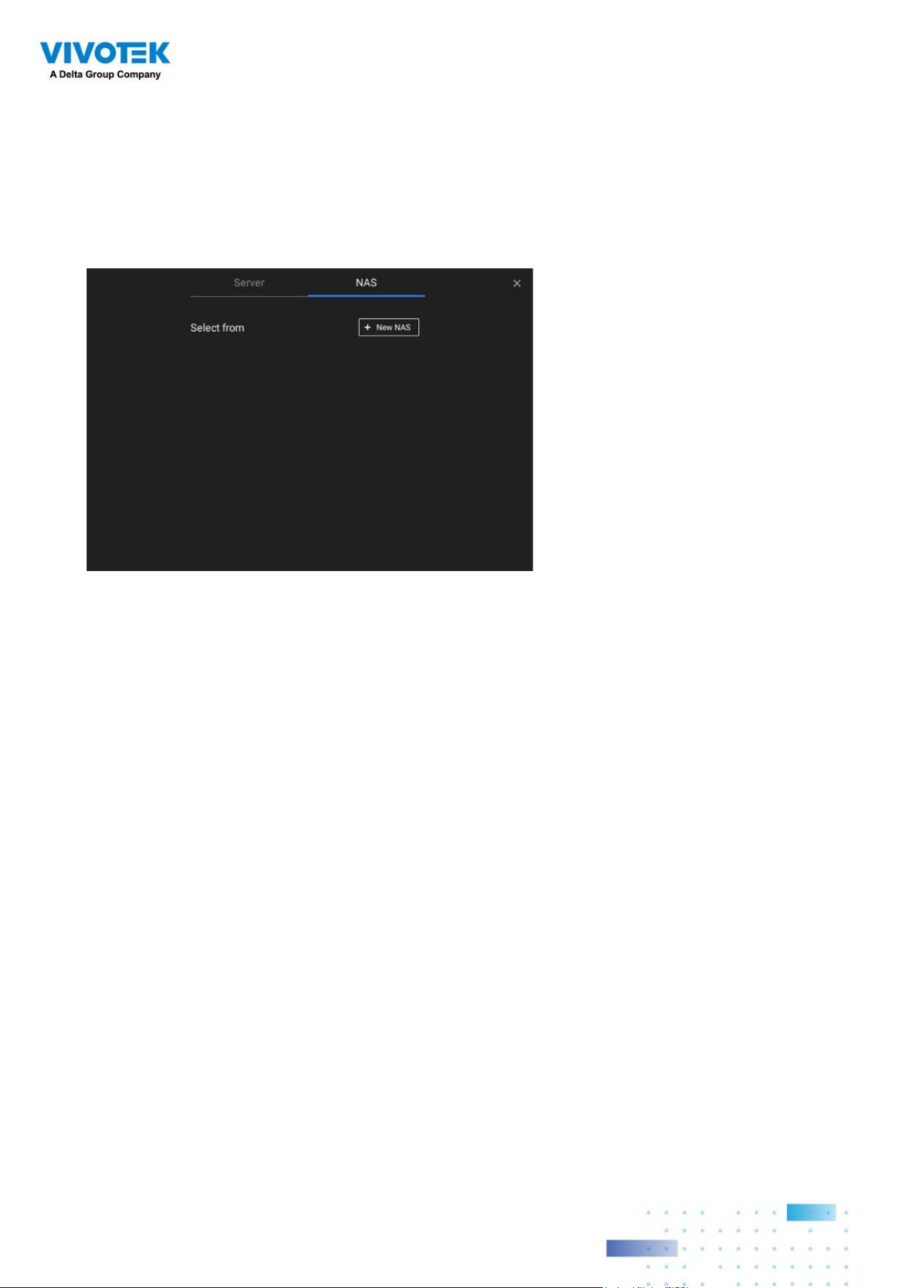
4. Click the + New NAS button.
4242
5. Enter the NAS storage's address and the credentials for access to the networked
storage. When done, click the Connect button.
6. The NAS storage should appear on screen. The connection may take several seconds.
Single-click on the NAS storage to select its network shares.
4343
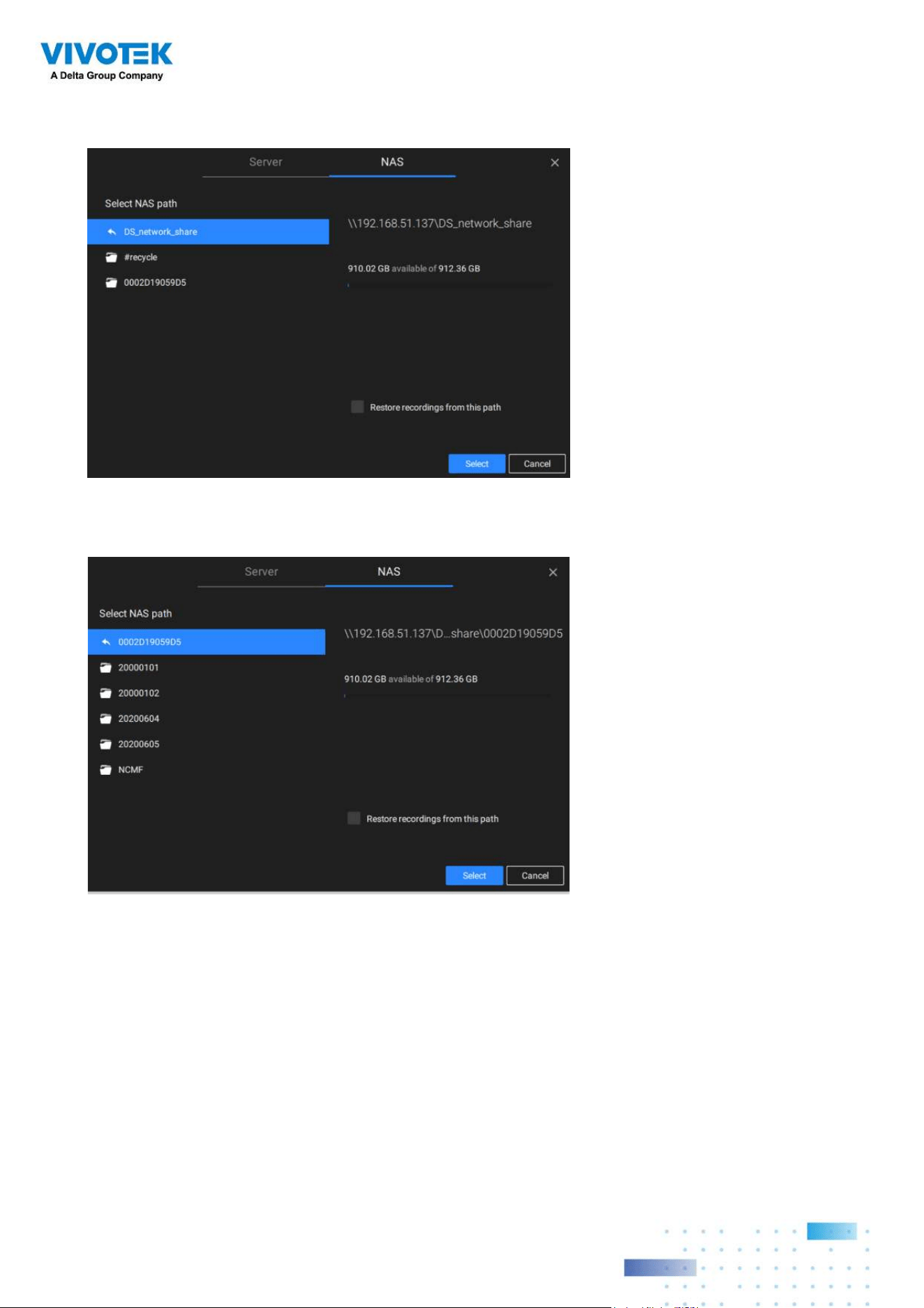
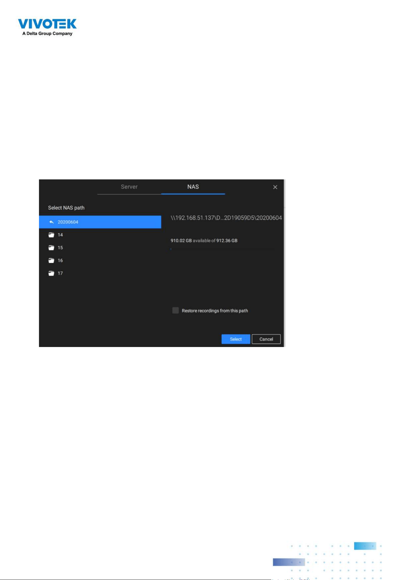
7. The NAS storage's network shares should be listed. Single-click to select a network
share.
8. Click Select when done. Note that you can repeat the previous process to select multiple
network shares from a single NAS storage.
4444
2-3. Storage
By default, VSS will check if the D: drive is available. If no other disk drives can be specified,
the system drive C: will still be defined as a storage option. Other disk drives in the system,
and the default storage volume (configured in the initial setup) will be listed.
You can add a NAS storage's share volume as the additional storage option. Enter the
necessary information for access to a network share. Enter and select a NAS path. The
share will then be available for video recording.
Select storage volumes each by a single click.
Click Ready to use to continue. The server will take several minutes synchronizing
configuration between server and cameras, and the time settings between them.
4545
2-4. Starting Up - Main
Page
You will be defaulted to the Live view once the main page displays. Another tab window is
the Search panel where you can search recorded events and recorded videos.
Live
Search
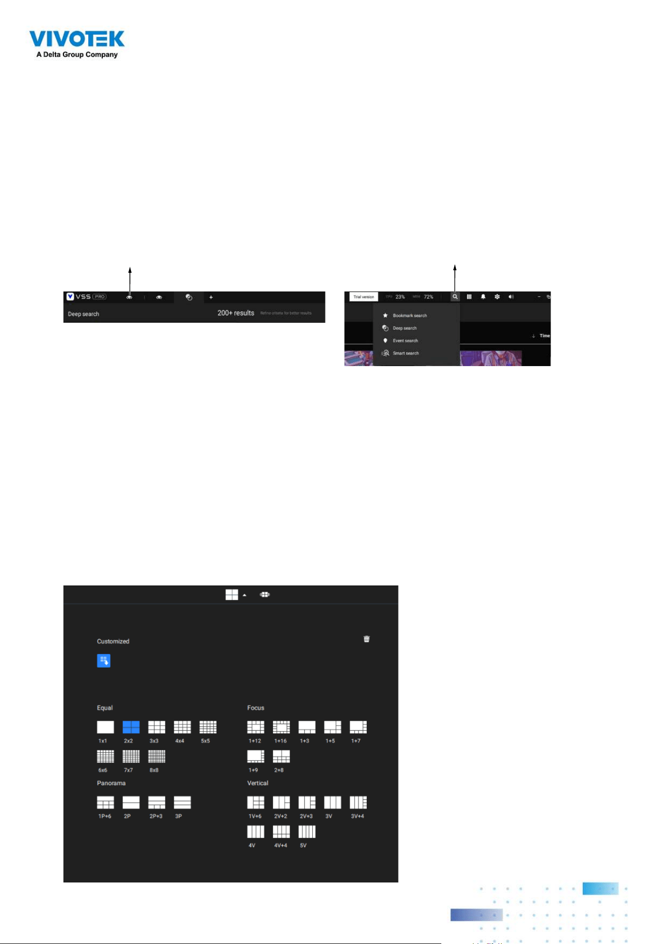
On the initial start up, the server should fill the live camera feed to the available 2x2 view
cells (4). You should then select a preferred layout, e.g., 3x3 or others, using the Layout
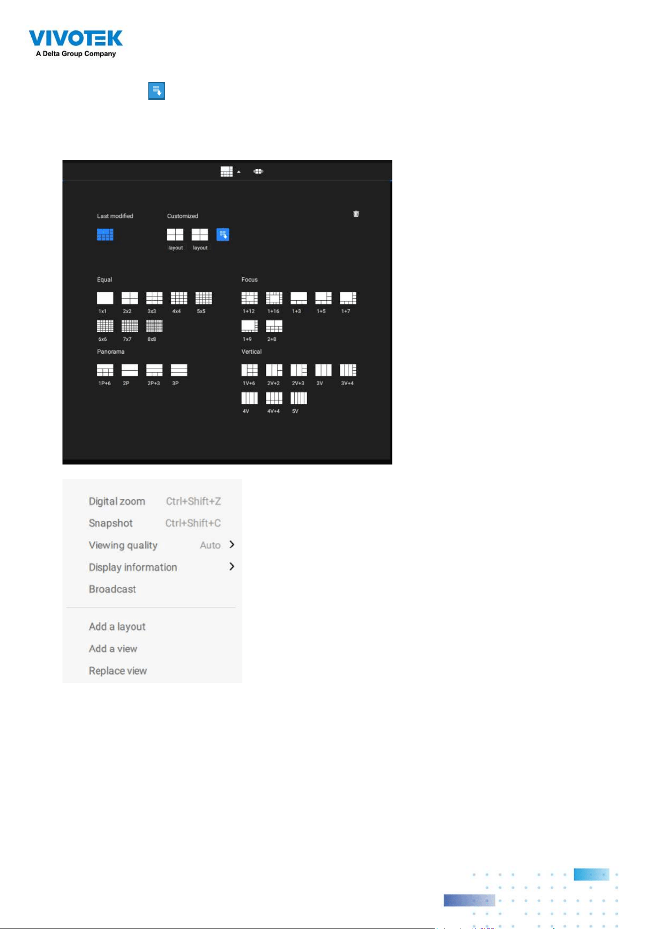
pull-down menu.
The available layouts are categorized into 4 types: Equal, Panorama, Focus, and Vertical.
Equal: 1x1, 2x2, 3x3, 4x4, 5x5, 6x6, 7x7, 8x8.
Panorama: 1P(Panoramic)+6, 2P, 2P+3, 3P. (applies to fisheye cameras)
Focus: 1+12, 1+16, 1+3, 1+5, 1+7, 1+9, 2+8.
Vertical: 1V+6, 2V+2, 2V+3, 3V, 3V+4, 4V, 4V+4, 5V. (applies to corridor view)
4646
To design and customize a layout, please refer to the Customizable Layout page.
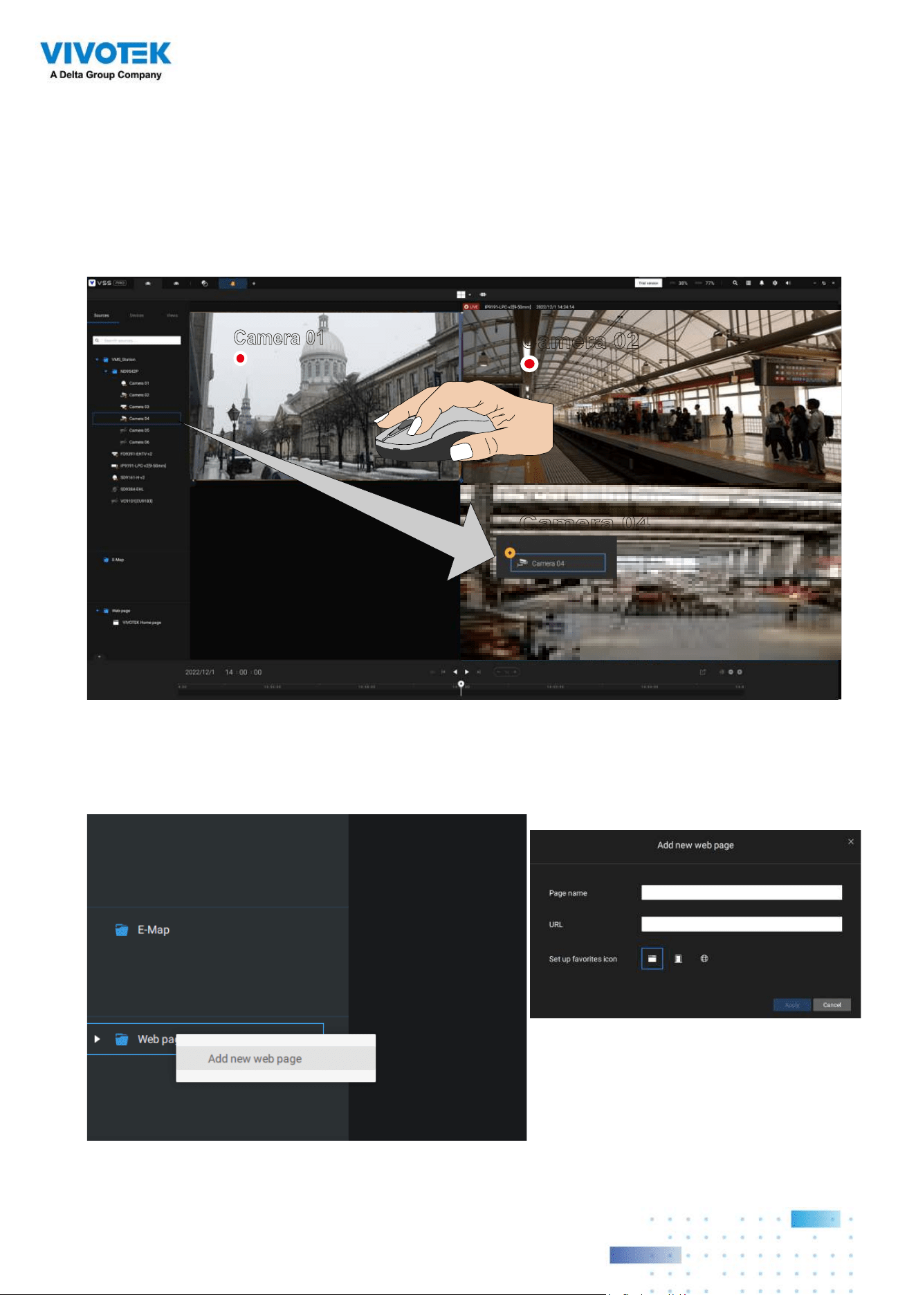
You can then fill in the view cells by dragging and dropping cameras into the view cells.
While dragging, a name tag displays. All cameras should be listed under the VMS_Station
Device Group.
You can swap two view cells by dragging one on top of another.
Camera 01
Camera 02
Camera 04
You can also configure a view cell to display a web page by a right-click on the Web page
option on the left device pane. Enter a name and the URL address.
When configuring a web page to be
displayed in view cell, You can select a
favorite icon.
4747
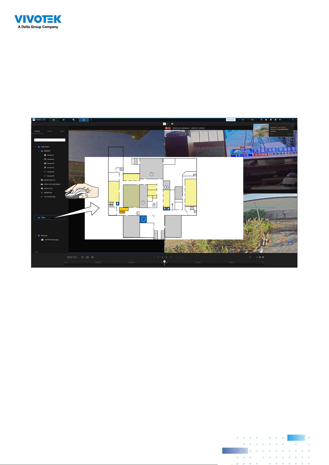
You can also fill in an Emap by dragging and dropping a pre-configured Emap into a
specific view cell. Click on the E-Map tab to select a pre-configured E-Map. Note that an
E-Map should be placed into a larger view cell.
Depending on the resolution of your monitor, a view cell can be too small for an E-Map.
For example, for an HD monitor (1920x1080), a single view cell from a 3x3 layout will
have a resolution of 640x360. View cells larger than 330 (width) x 300 (height) pixels can
contain an E-Map.
i
EXIT
EXIT
4848
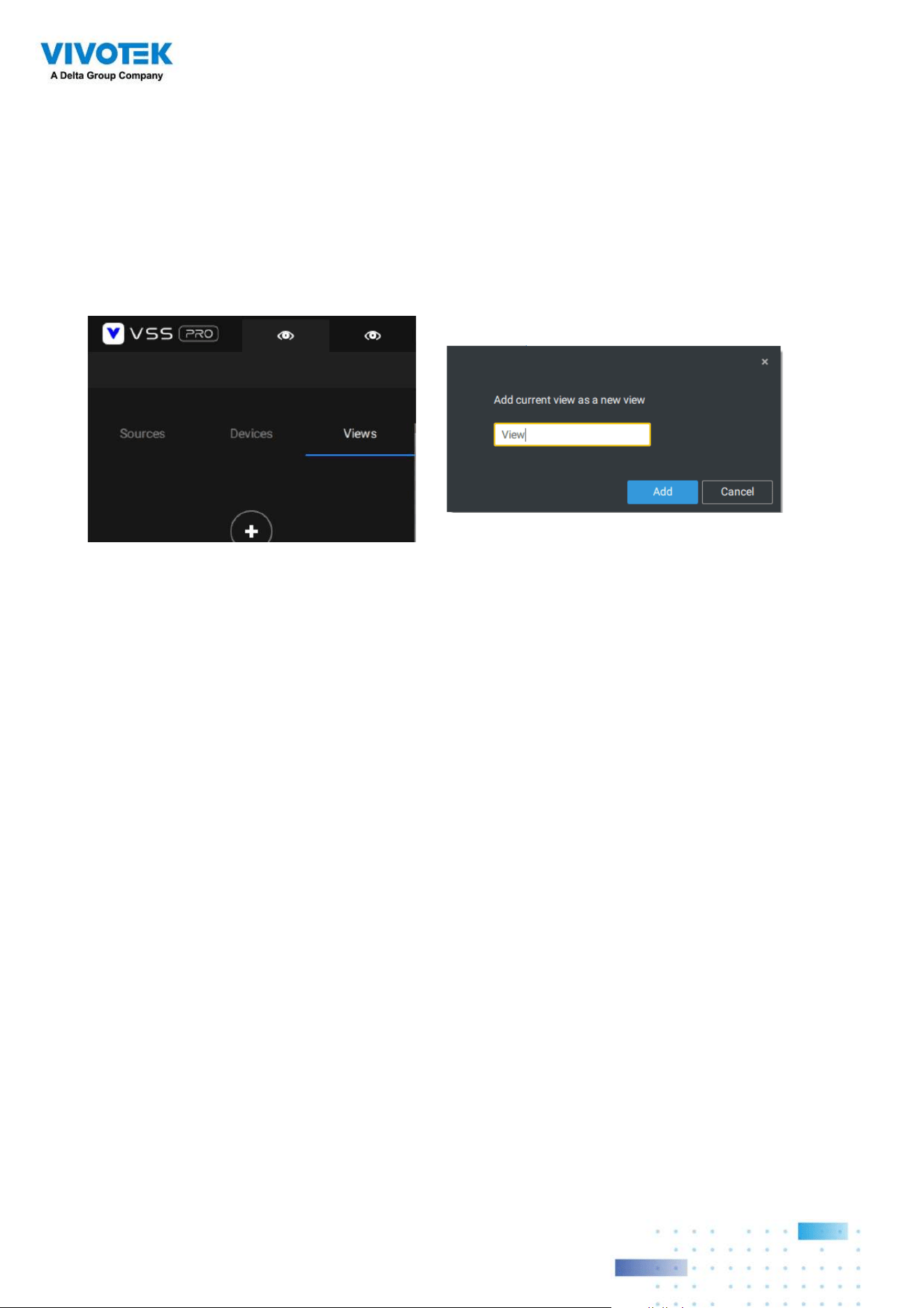
2-5. Saving a View
When done with arranging view cells, click the View tag.
Save your current layout and view cell arrangement as a new view.
4949
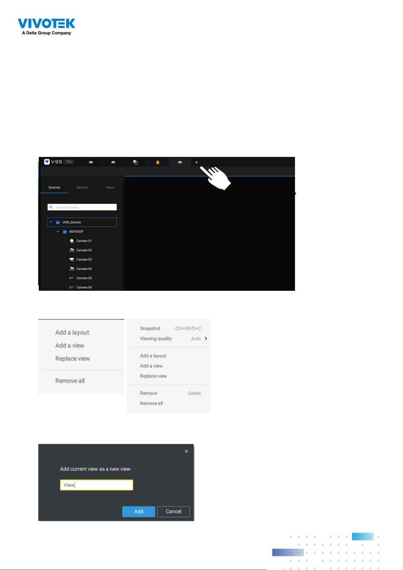
2-6. Add More Live Views
With many cameras in your deployments, you can click the New Tab "+" button to add more
Live views.
An empty live view will display, and you should repeat the above process to select a layout,
and fill in the view cells. When done, save the view.
Right-click on the screen to display the right-click menu. Select Add a view.
Enter a name for the new view and click Add to proceed. The new view will be listed in the
View panel.
5050
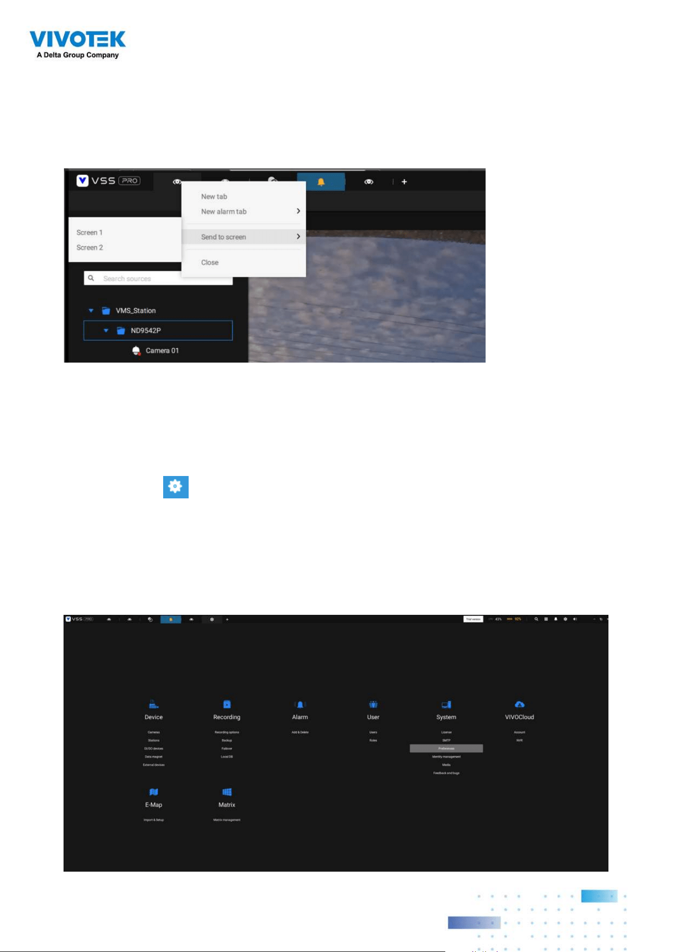
If you have multiple monitors attached to your server station, you can drag a live tab to a
different screen. In this way, you can display live views simultaneously on multiple screens.
Live views can be placed on multiple monitors. Please note that the number of monitors to
display live views is determined by the capability of your system.
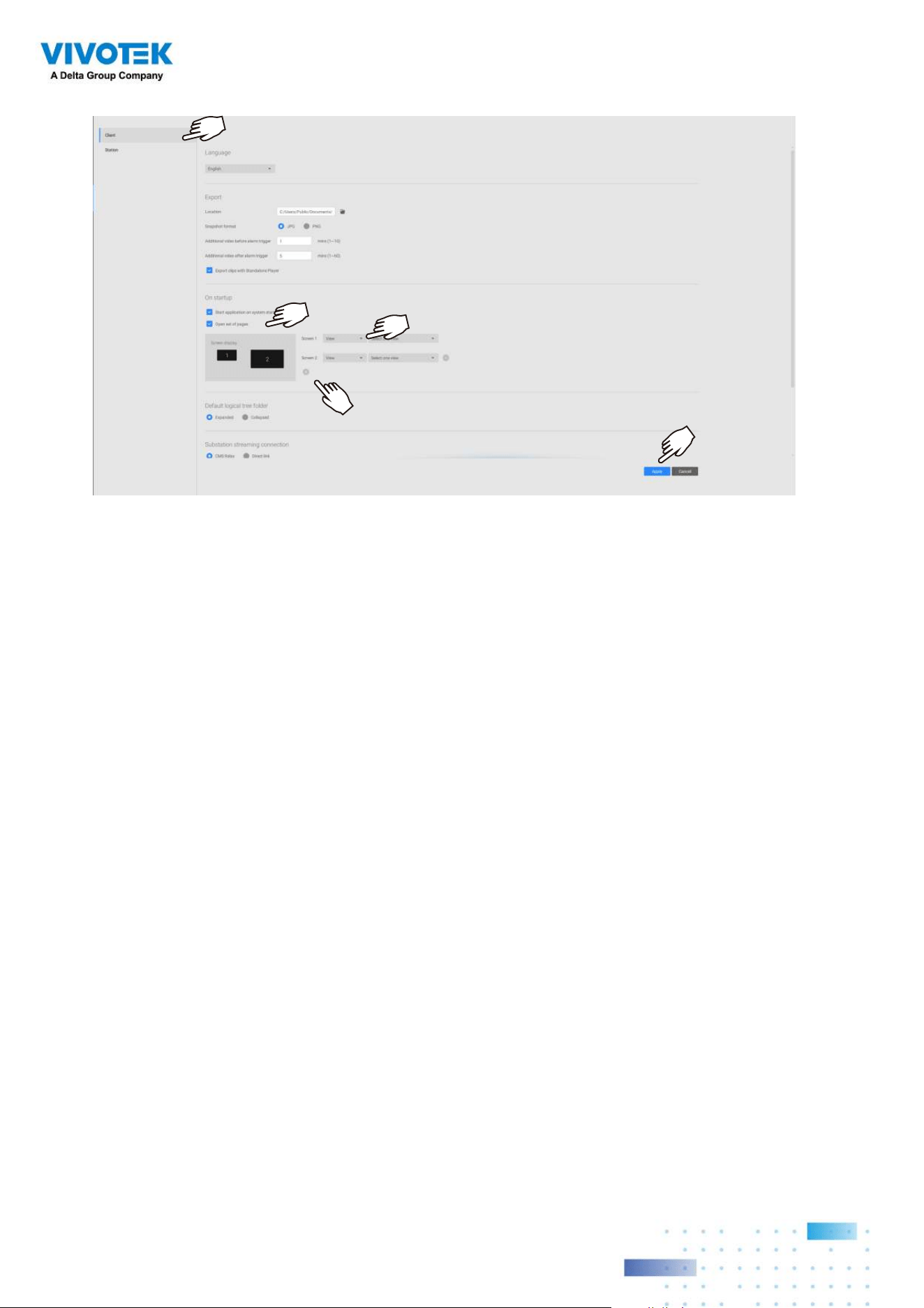
2-7. Save Your Preferences
Go to Settings > System > Preferences to save your current layout and display
configurations.
Select the options in the startup choices menu to decide what to display whenever
your VSS client starts. You can display Live view, Tour, Dashboard, E-Map, or Alarm tab
simultaneously on multiple screens.
5151
5252
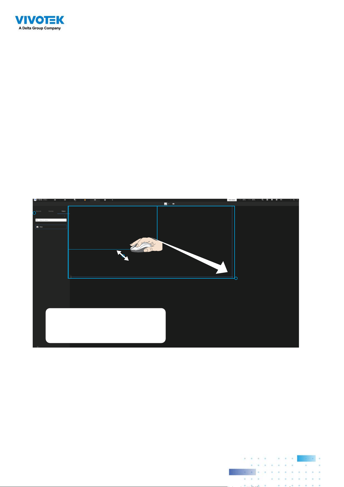
2-8. Customizable Layout
The standard layouts can be manually configured to form layouts of your choice.
Depending on the complexity of your design, you should start with a multi-cell layout.
Click and drag the corner mark on a view cell. Drag across the screen and release the
mouse button to enlarge the view cell. Choose a standard layout of many view cells, e.g.,
7x7 or 8x8, if you want to design a complex customized layout. You can create a special
layout, e.g., an especially wide view cell for a multi-sensor camera, such as the panoramic
MS-8392.
To abandon a customized layout, simply select a new layout from the layout window. You
can also use the Ctrl + Z keys to undo your changes on the layout.
Use “Ctrl + Z” to undo
layout change
5353
To preserve your customized layout, click to open the layout window. Click on the Add
current layout button. You may then change the name of your layout by a double-click
on its name.
To remove a configured layout, drag it to the garbage can icon on the upper right.
You can also right-click on the screen to display the Add layout option.
You can then click Device Group, and start filling your customized layout with camera
views. When done, click Add a view.
Also remember to save the current layout as a view, and save your configuration in
Settings > Preferences.
5454
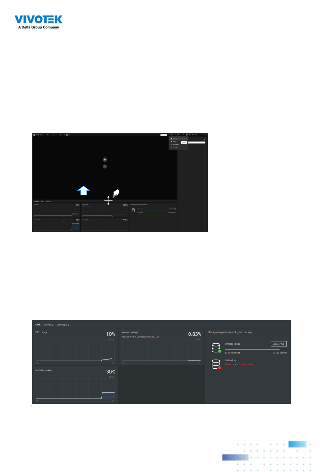
2-9. Dashboard
Select to open the Dashboard utility from the tool bar. The Dashboard displays the
system resources of a CMS server along with those of its sub-stations. This provides a
glimpse of the load on machines when performing the recording and monitoring tasks.
Mouse over the edge of the bottom row to reveal the expansion mark. Pull the status row
up to display the system resource statuses.
If you have multiple LAN cards or virtual HBAs, the status row can be pulled to reveal
all of their statuses. The storage volume status is also displayed in terms of recording
and backup with the total, used, available size displayed. If a volume went down or is
disconnected, notifications will appear on the status panel.
The possible system abnormalities
can be:
CPU utilization over 90%
Memory usage over 90%
Network usage over 90%
Camera disconnected
Station disconnected
5555
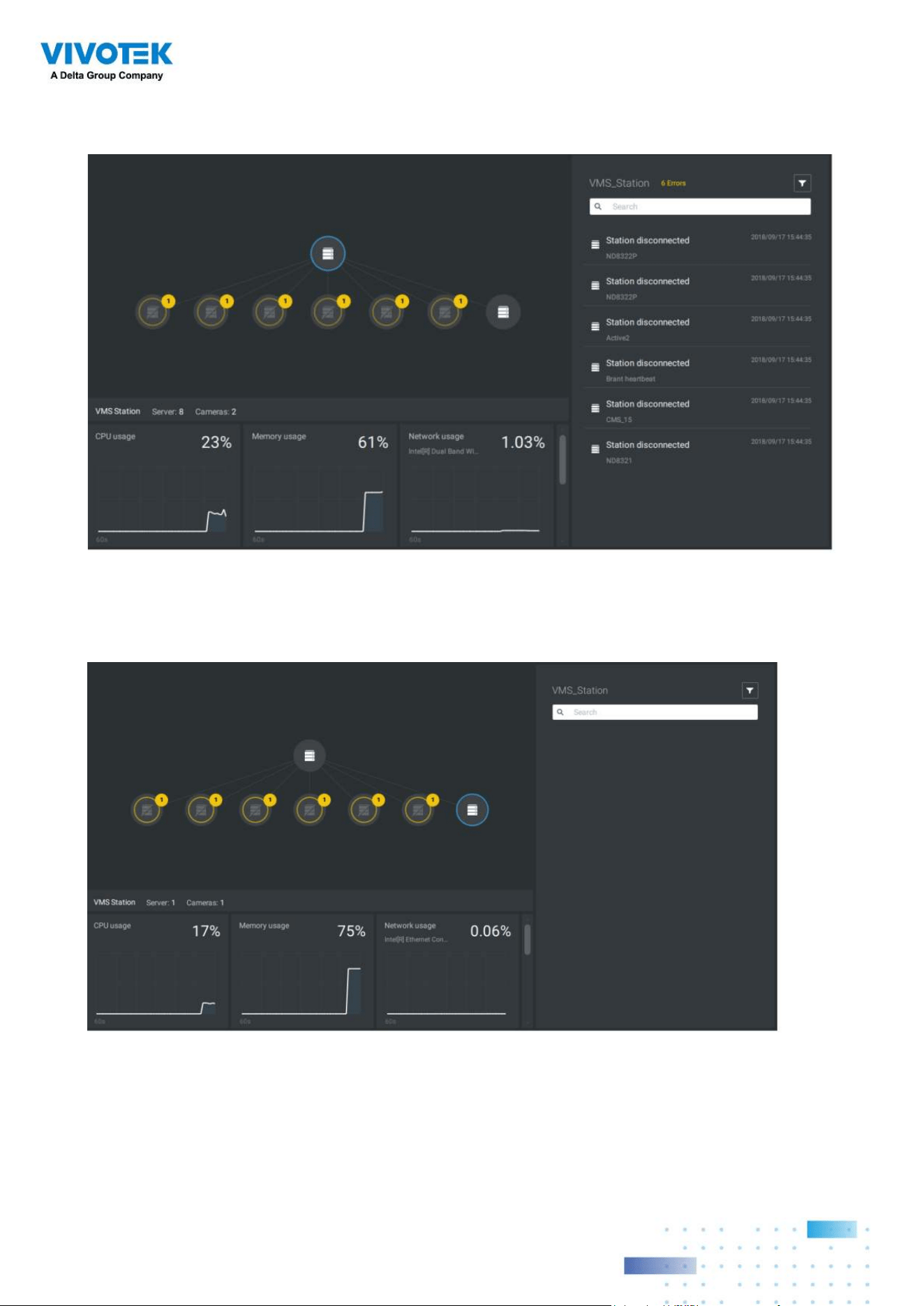
If you have multiple sub-stations, single-click to select and reveal their individual status,
including CPU usage, memory usage, network usage, and storage usage.
Note that VSS servers of the earlier revisions and NVRs running older firmware do not
deliver their statuses to your Dashboard.
5656
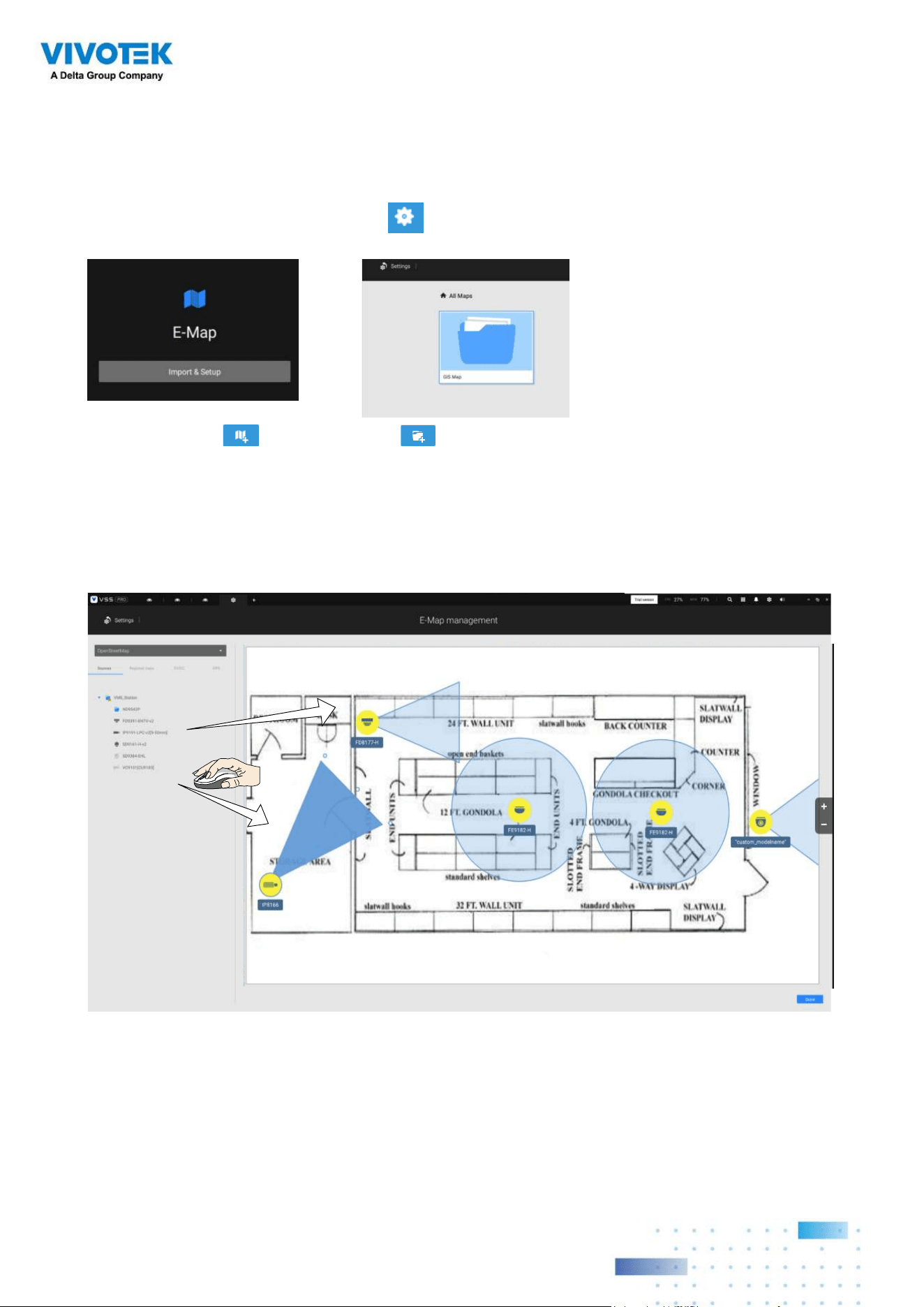
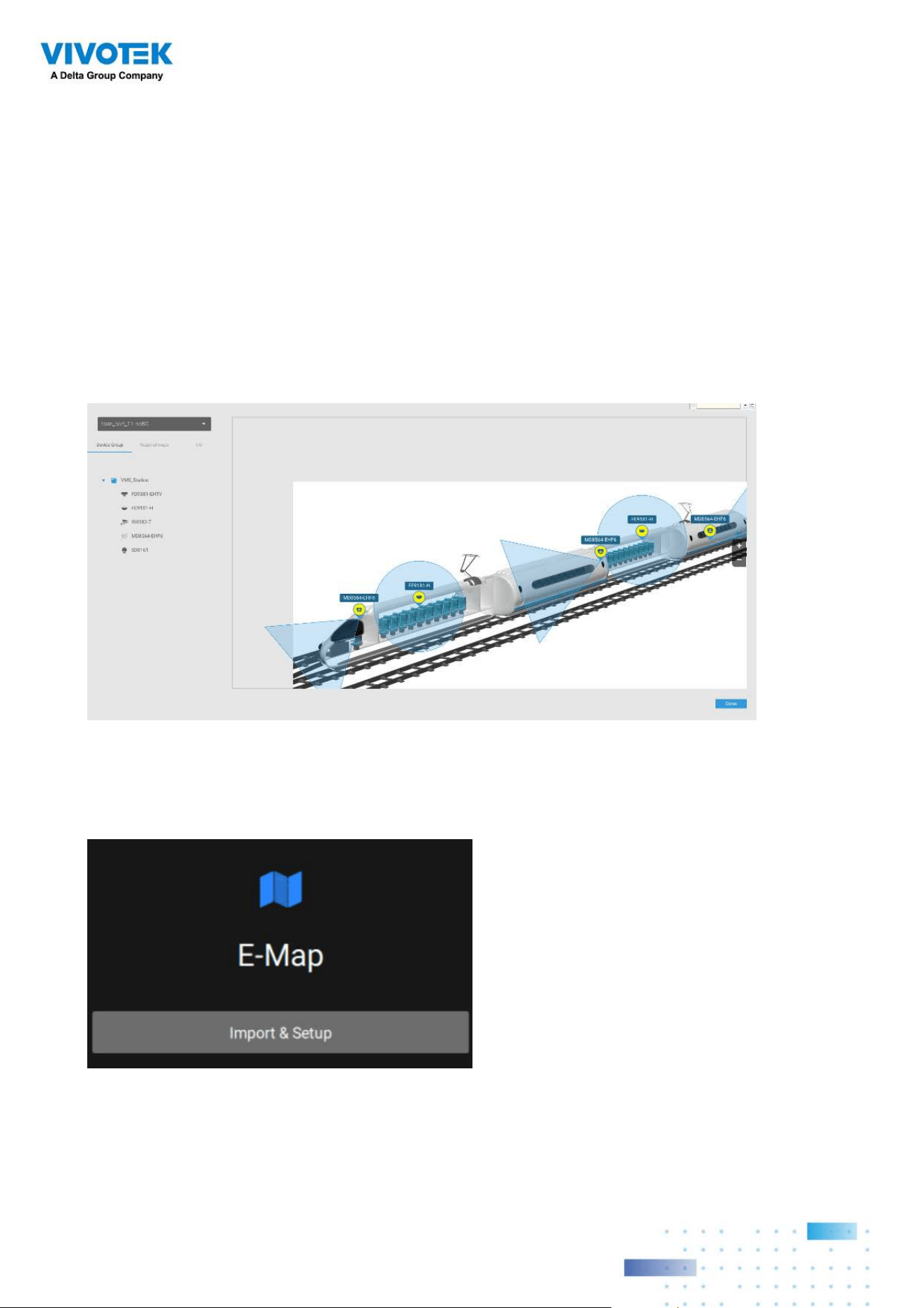
2-10. E-Map
To create your E-Map, click Settings . Click Import & Setup. Click E-Map.
Click Import file or Import folder . An entire folder can be imported.
When done, double-click on the snaphot of E-Map image to configure the E-Map.
Your cameras will be listed on the left. Drag and drop the cameras to the corresponding
locations on the map.
5757
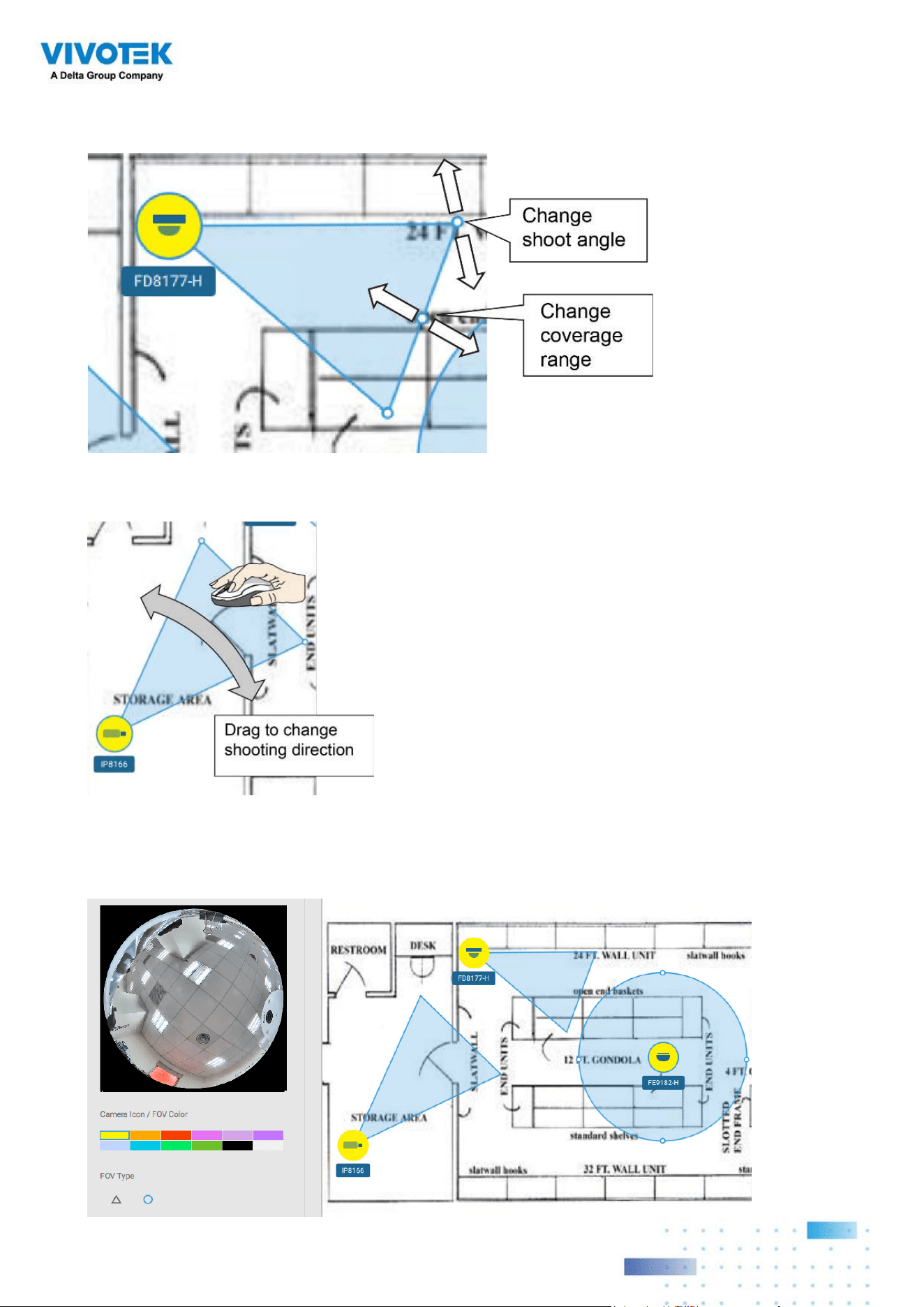
When the camera is in place, drag the FOV indicators on the edge to change the shooting
angle and the coverage range.
Drag the FOV to change the shooting direction to match the actual installation.
Click on the camera icon. You can also change the color of camera icon and the FOV type.
Fisheye cameras, when ceiling mounted, have a round shape coverage.
5858
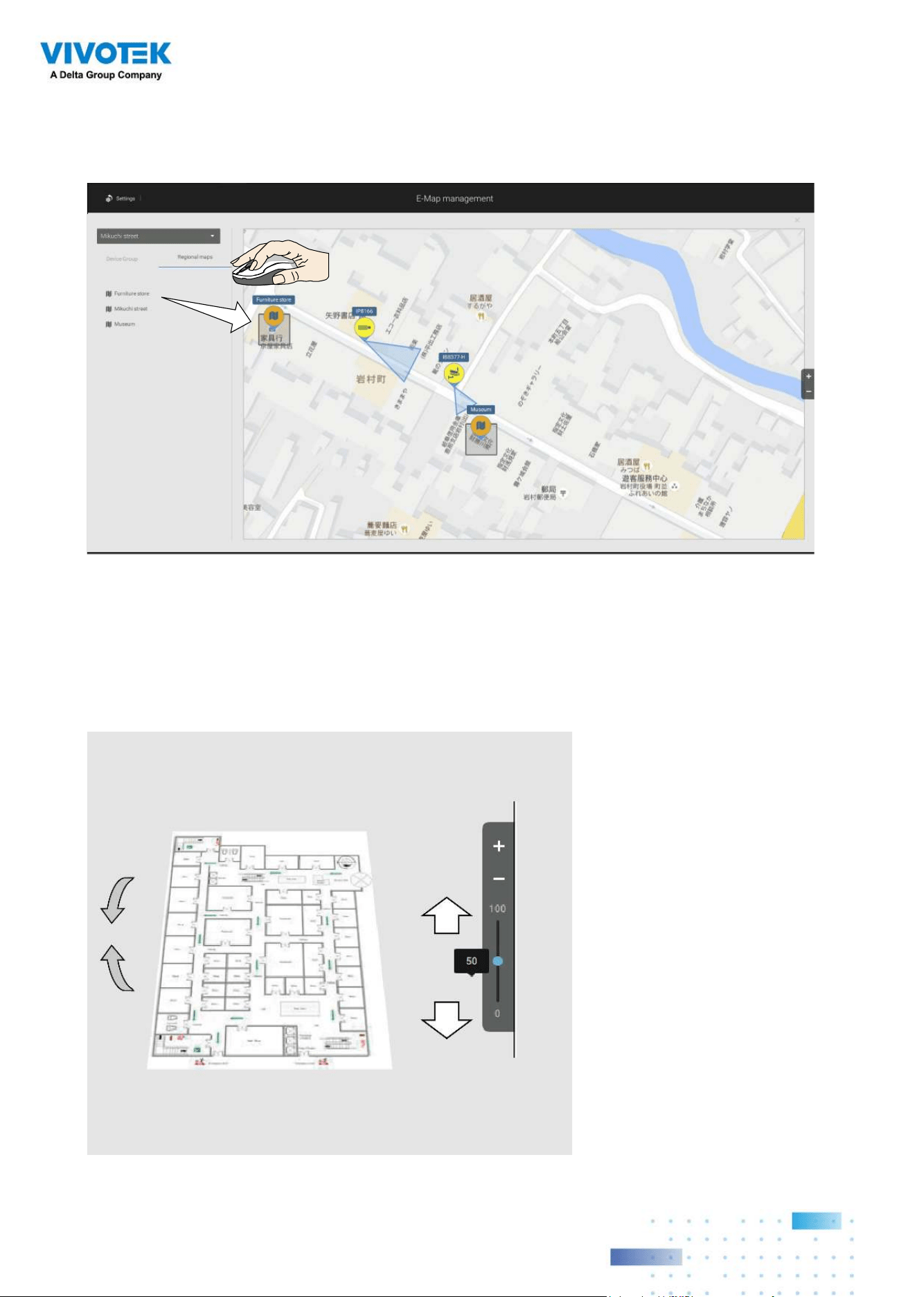
If you have a larger regional map that covers a geographical area, say, a street block, you
can drag one or many E-Maps into it. For example, you can place another E-Map that is
used to indicate the camera deployment inside a building that is located on the street.
To see live streams from cameras, click on the camera icons in the E-Map.
When configuring an E-Map, you can use the tilt bar on the right to tilt the E-Map image.
Doing so creates a sense of distance and depth of view.
5959
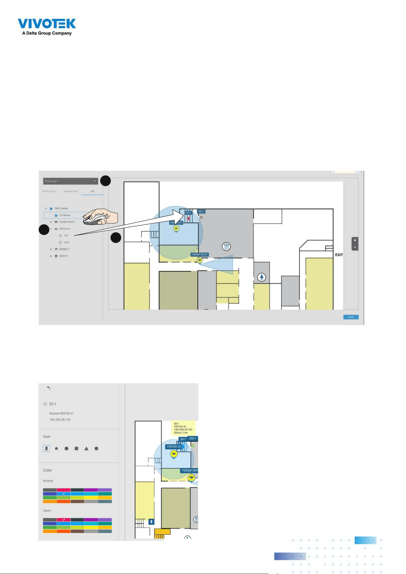
Placing DI/DO Devices
I/O devices can also be planted into an Emap, such as alarm or various kinds of detectors.
The I/O boxes (such as Advantech's Adam series) or the DI/DO connections on an NVR
also apply.
1. Select a floor map from the pull-down menu.
2. Unfold the sub-trees beneath the network camera, (taking camera DI/DO devices as an
example).
3. Select a DI/DO device. Click and drag to a preferred location on map.
2
1
3
4. When a DI/DO device is selected, you can select the display colors of its icons. Configure
different colors for the device status when it is normal or triggered.
5. When done with placing all DI/DO devices, click the Done button on the lower right of the
configuration screen.
6060
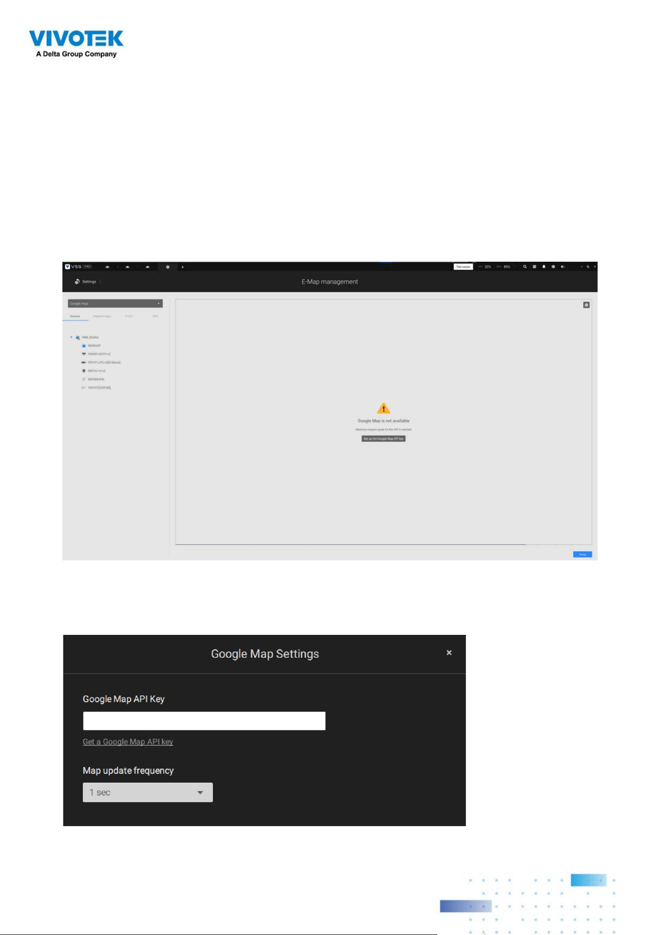
Configuring GIS or Google Map and GPS
Since Google Map changed its access policy, using the Google Maps feature requires user
entering a billing API key. Using Maps, Routes, and Places APIs requires an API key.
For applying a Google API key, https://cloud.google.com/maps-platform/maps/
Visit Settings > Emap > All Maps.
Enter the Google API key you previously registered (if using Google Map).
6161
NOTE: In this revision, Google Map only supports installation on a GPS-enabled vehicles.
Placing cameras on a static location on Google Map is currently not supported.
Before configuration on a Google Map, you should prepare an E-map drawing for special
installations, such as that on a vehicle. The vehicle, e.g., a train, should come with a GPS-
GSM/GPRS module to collect the position information and pass this information to a web-
server. As new data is constantly inserted to the database, the VSS server will update the
location information containing coordinates, speed, distance, time, etc.; and when video
recording is required, the location information and time tags will be available.
This applies to a mobile NVR that comes with GPS functionality.
Open the E-Map Import & Setup window.
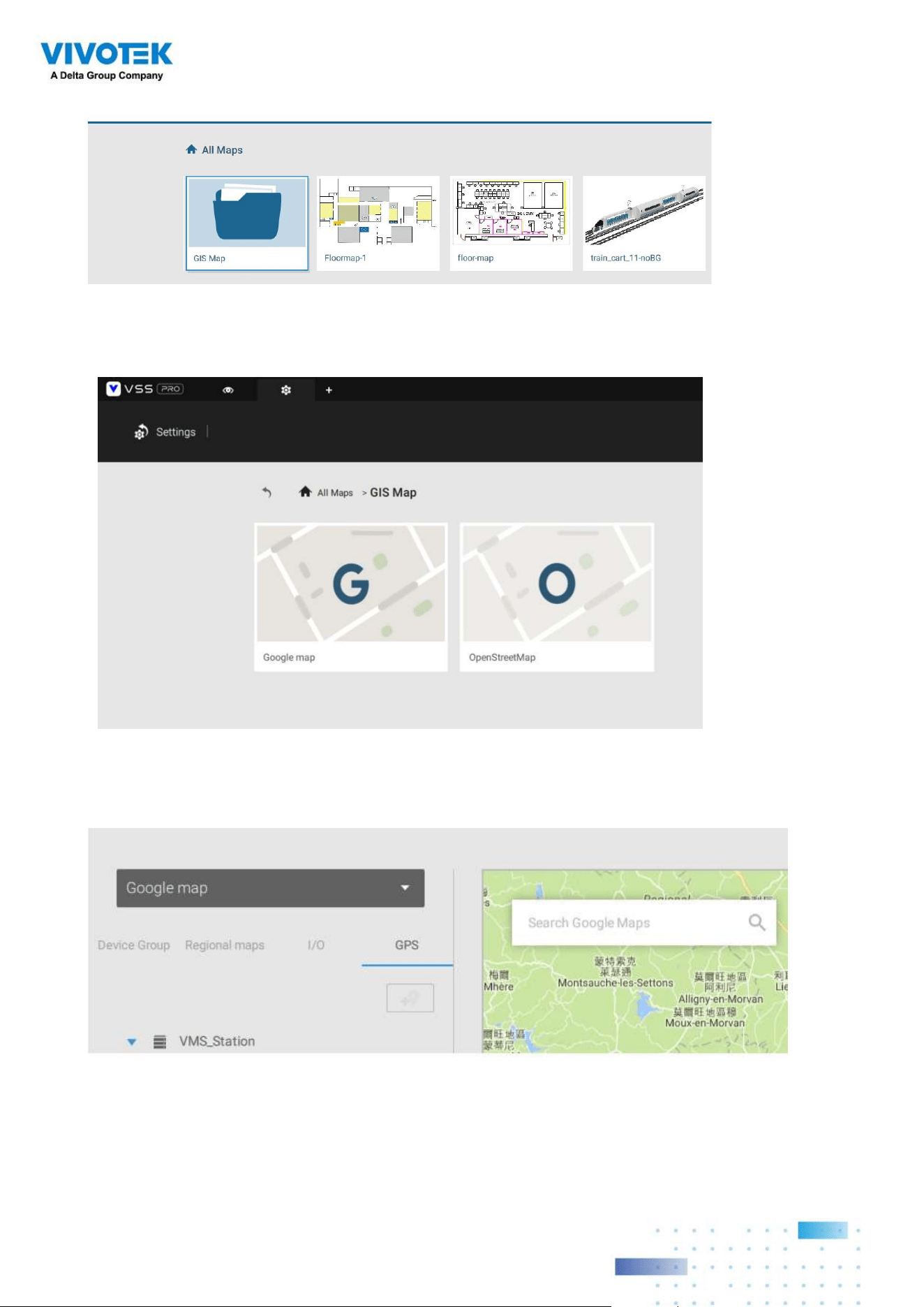
6262
Click to enter the GIS (Geographic Information System) Map and then Google Map window.
Click on the GPS tab. Select a VMS station or mobile NVR to apply the configuration, and
then select the GPS Add button .
Click on either the Google map or the OpenStreetMap.
6363
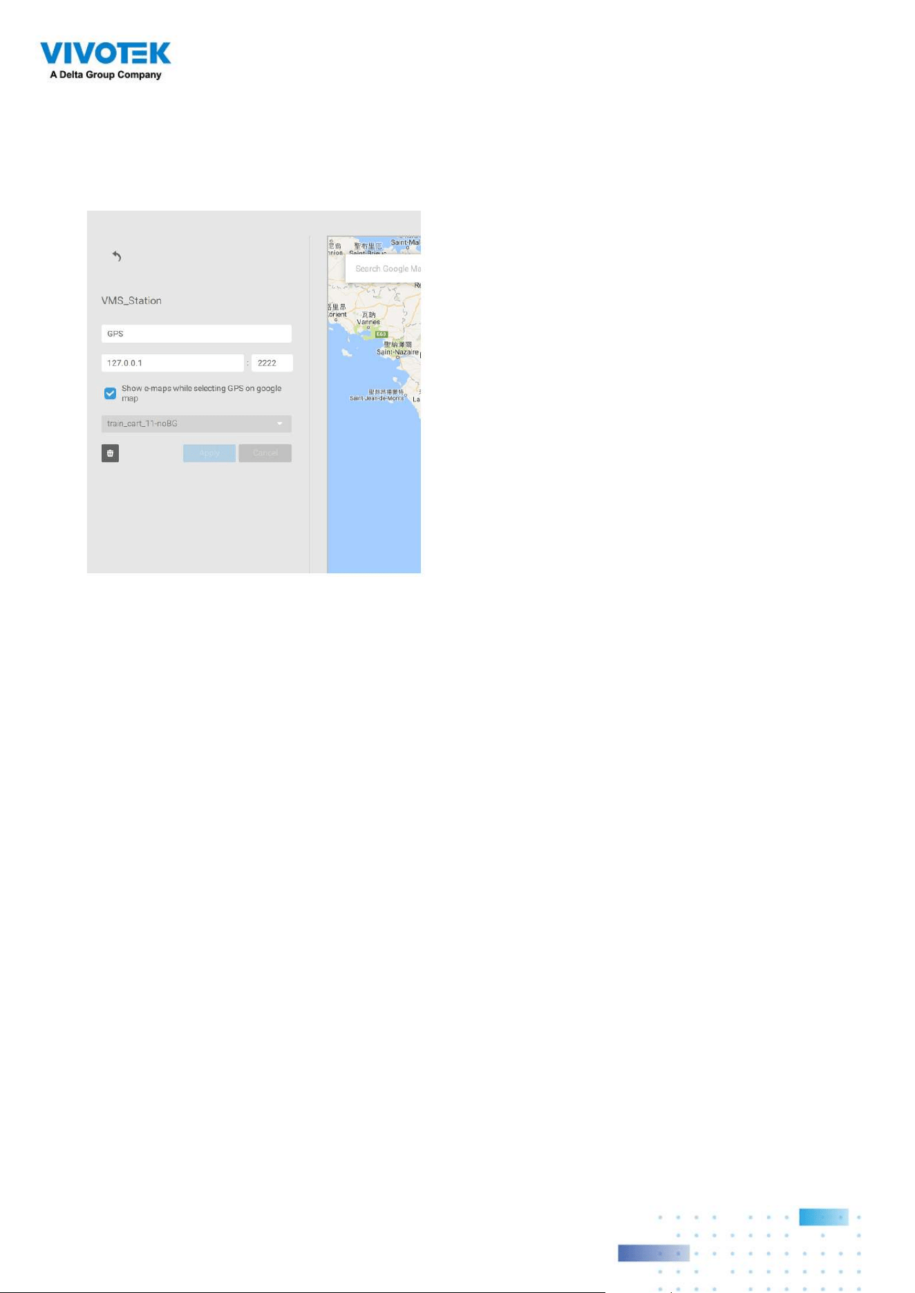
Enter a name for the GPS/GNSS server on the vehicle, its IP address, and server port
number. You can select an E-map that will display when you click on the GPS location icon.
Select the checkbox and an E-Map that corresponds to the deployment on the vehicle.
When done, click the Apply button.
You can skip this setting for the mobile NVR
that comes with a built-in GPS module.
6464
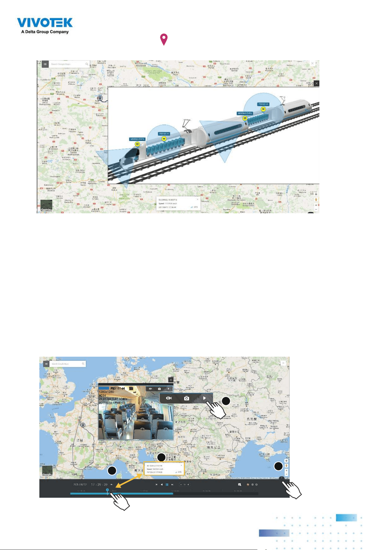
You can click on the location icon
to bring up the E-Map. The coordinates, speed, and
time information also display on the map.
You can click on any cameras on the E-map to search through past recordings. One click
displays the live view. A live stream window will display.
To search and review recordings when an event occurs,
1. Click on the Playback button.
2. Click the Pane button to display the Playback control panel.
3. To search for the video of past events, pull the Playhead to a point in time on the
timeline.
4. The GPS coordinates and time will change to those corresponding to the time you
selected. You can then acquire the corresponding location information while tracing the
occurrence of an event.
29.91 fps 0.97 Mbit/s
2017/4/11 17:46:10
PLAYBACK
FE9181-H
1280x1280
H264
2
1
3
4
6565
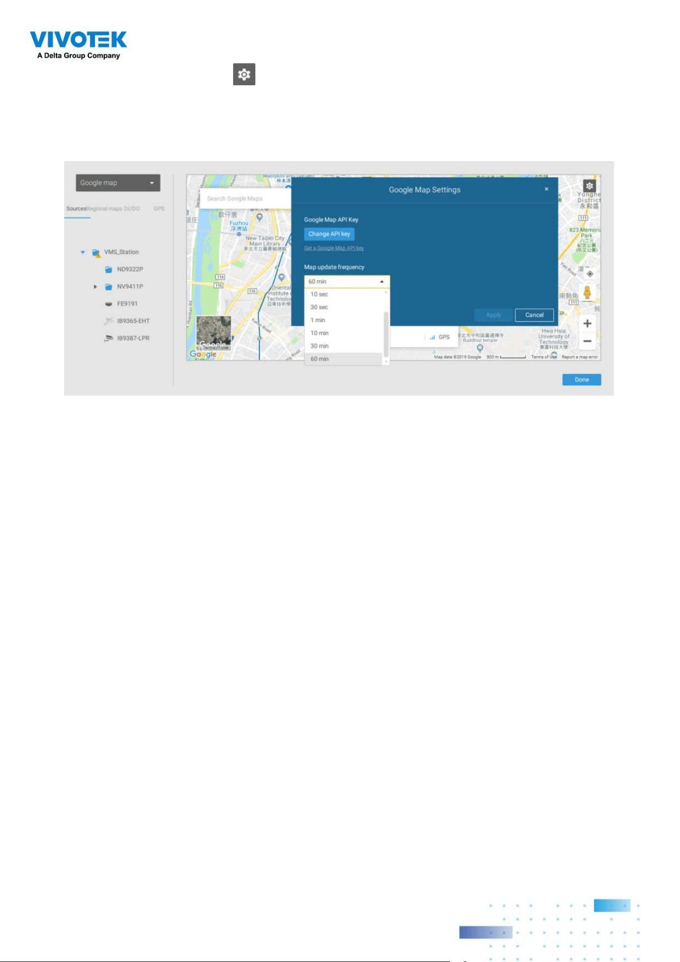
Click on the Setting button on the map to bring up the Map update frequency option.
Your GPS target may travel to the outside of the map through time without the map being
updated. The map will update by the interval you configure here.
6666
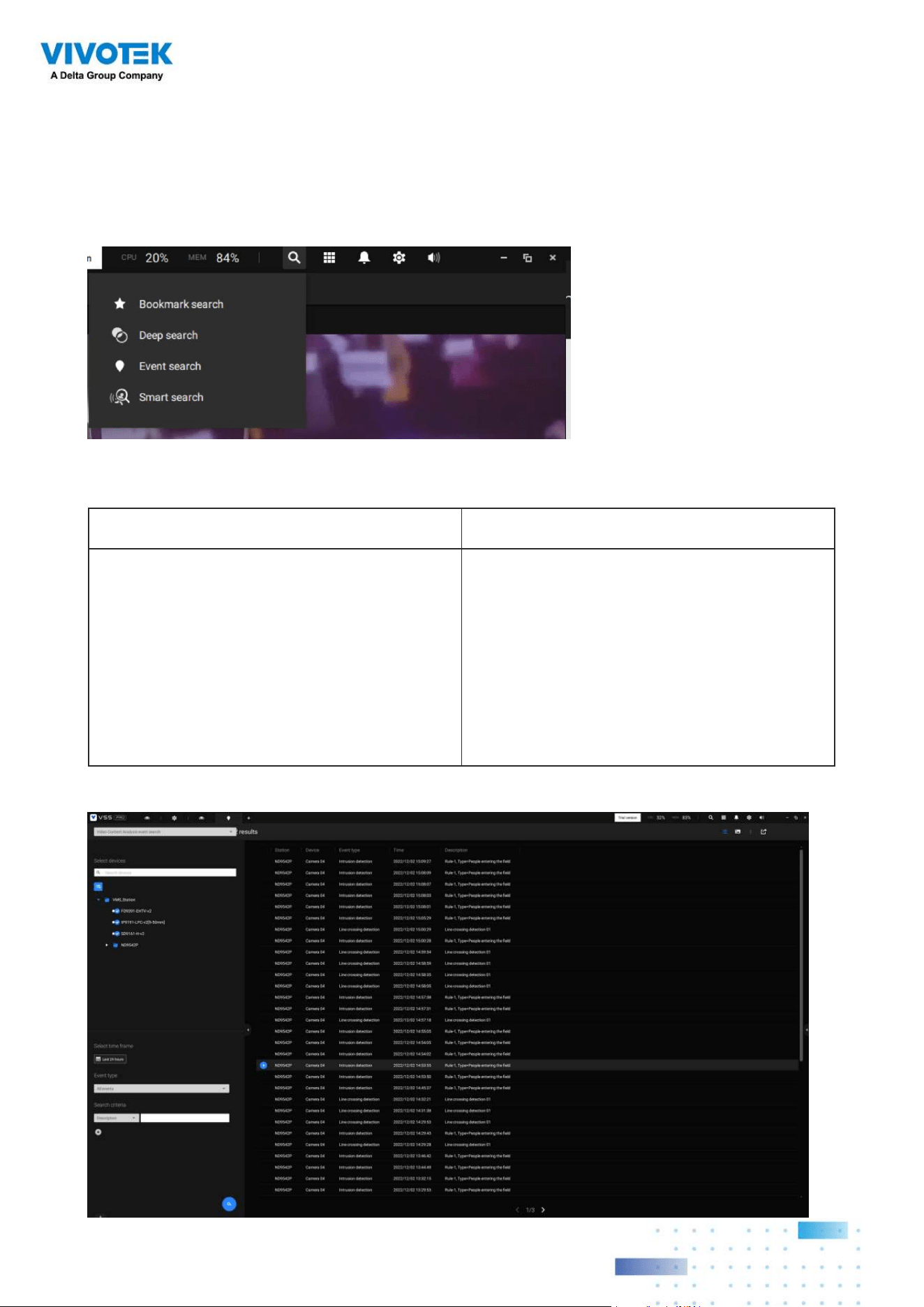
2-11. Event Search
The Event Search window is accessed from the top tool bar.
Below is the comparison between the Alarm list and the Event search windows:
Alarm List Event Search
Reports alarms triggered by user-
configurable events, such as DI/DOs,
Motion Detection, tampering, VCA analytics,
cybersecurity, and so on.
The events on the Event Search window
require no user configurations. The Event
Search window displays system events and
provides a glimpse of all general events.
The event types include: General events,
Video Content Analysis events, and Trend
Micro IoT Security events.
The sample screen for VCA-related events is shown below:
6767
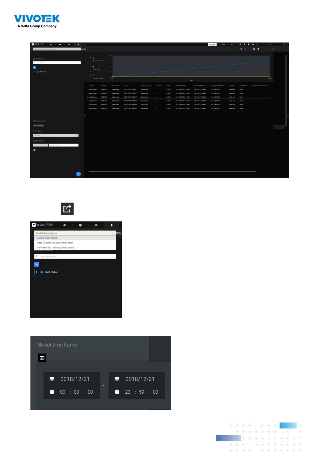
From the Search Event window, you can view and search events by its event types, and use
the Export button to save a record of these events (in the CSV format).
The sample screen for network security-related events is shown below:
Use the calendar tool to specify the span of time as the search range.
6868
Use the Event type menu to narrow down the types of events. Select or deselect the event
types for search. You may also enter one or several keywords as the search criteria in the
following menus.
Click the search button to generate search results.
6969
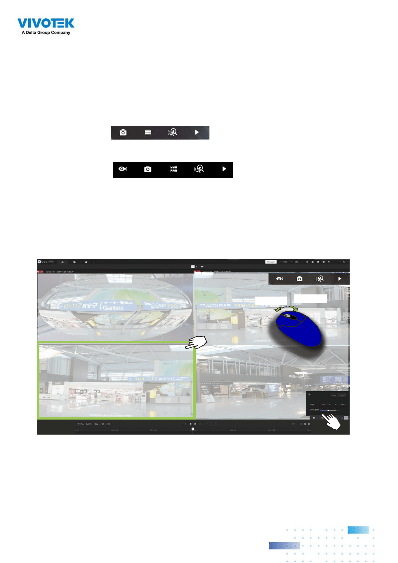
2-12. PTZ Control
PTZ on this page refers to the mechanical PTZ. The discussion on this page applies
to cameras that come with PTZ mechanisms that are capable of directional and zoom
control.
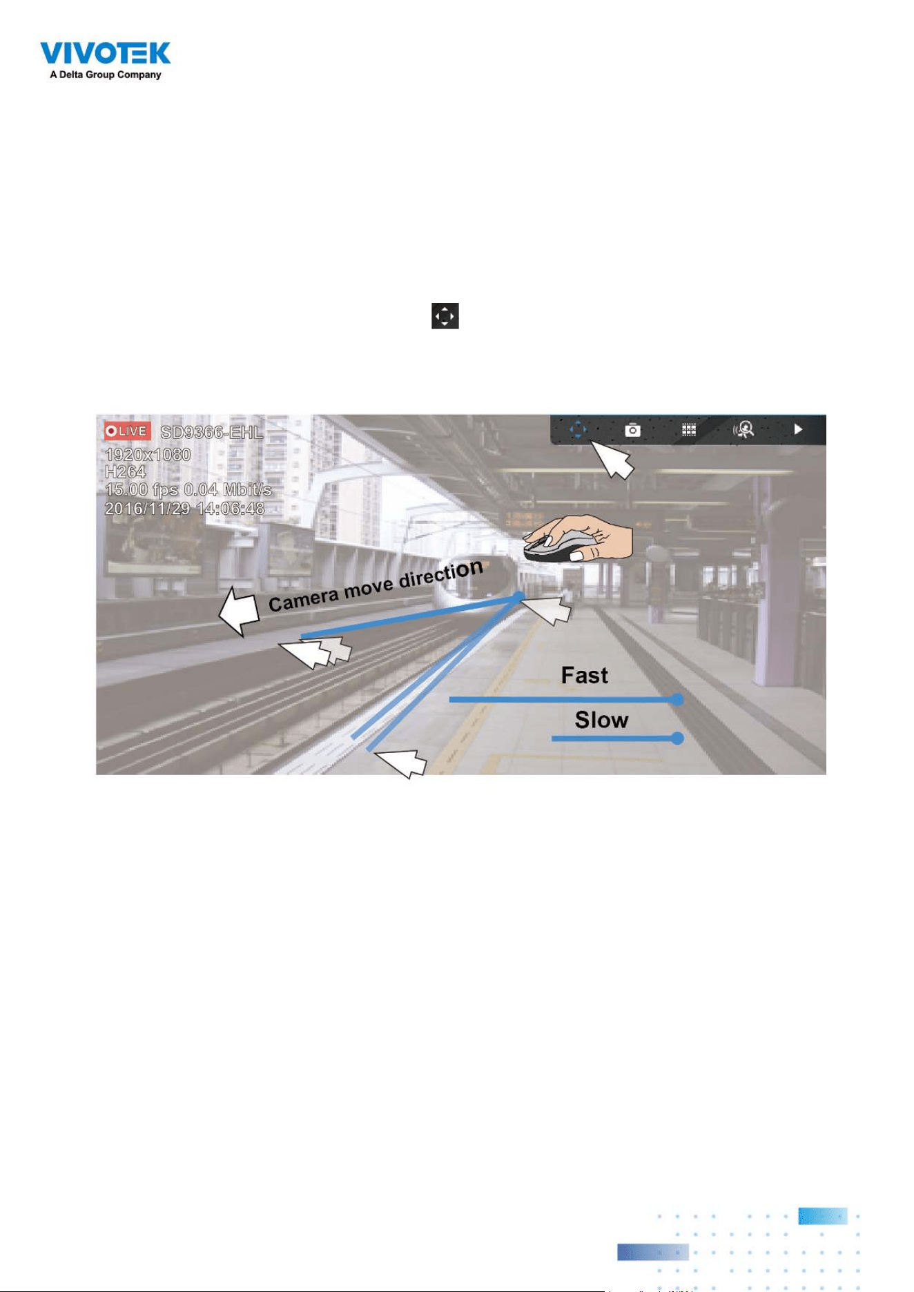
To begin the PTZ control, click on the PTZ button.
Click and drag your left mouse button across the screen, towards the direction you wish to
move. A light blue trace will appear. The longer the trace, the faster the move.
Note that while the camera is moving, you can change the move direction keeping the
mouse button hold down. Release the button to stop moving.
See Appendix D Joystick support if you use VIVOTEK's joystick.
7070
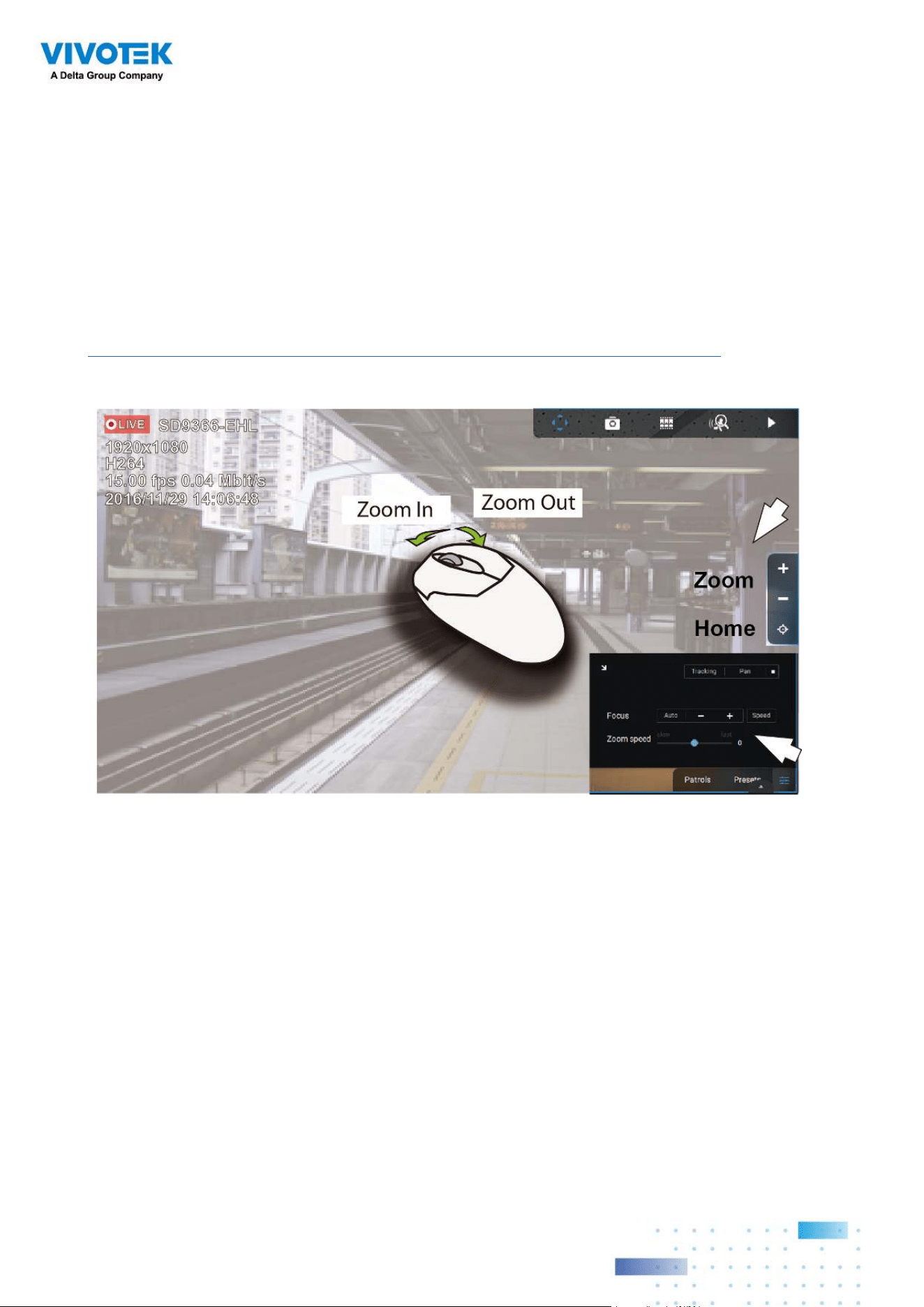
You can also use the mouse wheel to zoom in or zoom out. You can also mouse over the
right side of the screen to display the zoom button. A home button is also provided.
The Patrol, Presets, and PTZ control panel is located at the lower right of the screen. You
can click to begin a pre-configured patrol, preset points, or enable a Tracking or Pan action.
You can also adjust the Zoom speed, and/or manually adjust the Focus and the Focus
speed.
See Appendix H Smart Tracking for how to enable the Smart Tracking feature.
7171
2-13. Playback
To start the playback function, select a camera's view cell (whether in full view or ordinary
cell size), then click the playback initiative button ( or ). The button can be found on
the upper right of the view cell or at the lower right corner of the view cell in the full view.
Default Time: When started, system normally rolls back to the start of the hour, e.g., your
current time is 10:30:00, and the default playback position on the timeline is 10:00:00.
Playback control can be found in 3 places:
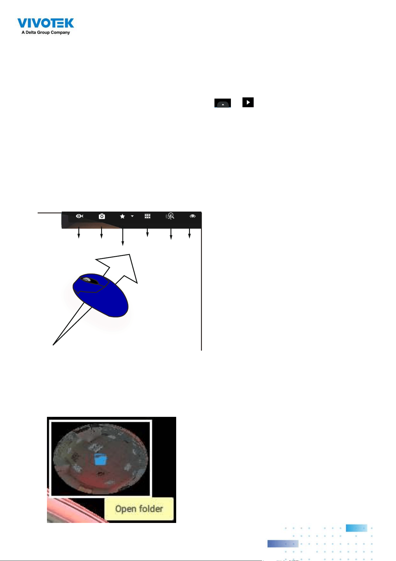
1. Float Panel: When Playback is started, swipe your mouse to the upper-right of the view
cell to display the Playback float panel.
Fisheye
Dewarp
Snapshot
Bookmark
Thumbnail
search
Smart
search II
Liveview
Fisheye Dewarp: For a fisheye camera, you can select different dewarped views during a
playback. Click to select an option.
Snapshot: Click to take a snapshot. A small floating window will stay for 2 seconds. You
can click the folder icon to access the snapshot files.
Note that a dewarped, regional view allows producing a snapshot of the regional view.
7272
Bookmark: If you find anything of your interest when viewing the playback, click this
button to create a bookmark. It helps when you need to return to the point in time after
you review all through the recorded videos. Note that the bookmarked video clips are
free from storage recycles. They will not be erased when storage runs short and needs
to be recycled.
Smart search II: Smart search II is an independent function. See page 99 for details.
Liveview: Click to return to Live view.
2. Right-click Menu: Right-click on the Playback screen to display this menu.
Digital zoom: If you find anything of your interest when viewing the playback, click this
button to create a bookmark. It helps when you need to return to the point in time after
you review all through the recorded videos.
7373
Synchronized play: When enabled, all cameras in the same view will be playing the video
of the same point in time.
The following commands are general purpose commands.
Snapshot: Click to take a snapshot. A small floating window will stay for 2 seconds. You
can click the folder icon to access the snapshot files.
Bookmark: If you find anything of your interest when viewing the playback, click this
button to create a bookmark. It helps when you need to return to the point in time after
you review all through the recorded videos.
Display information: By default, all display elements will appear on screen for all
playback windows. You can use the Edit display information to select more display
elements.
They include:
Status, Camera name, Server time, Codec, Resolution, Network throughput & FPS, Fit
screen with ratio, POS transaction details (for POS), Data magnet data (Data overlay on
screen / Hide data after idle), Motion detection, Rules (VCA), Rule name, Motion cells,
Tracking block, Tracking dot, Exclusive area, People detection area.
7474
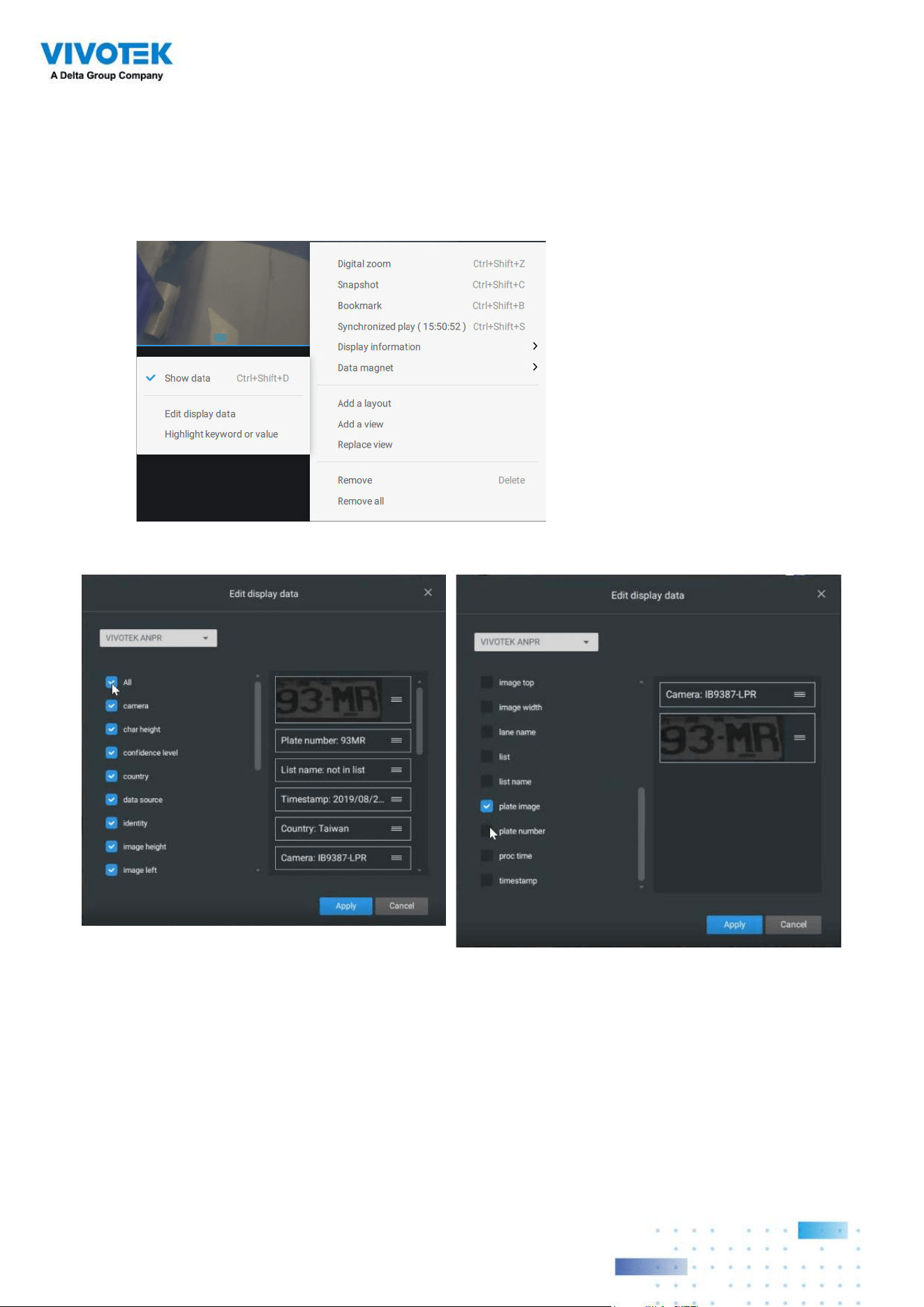
Data magnet: For 3rd-party applicatioins, such as VIVOTEK's license plate recognition
software, you can select to display different types of information. You can use the Edit
display data to select or deselect the display elements.
Please note that the display elements can vary for different applications.
Below are the sample screens for applications implemented via the Data magnet.
7575
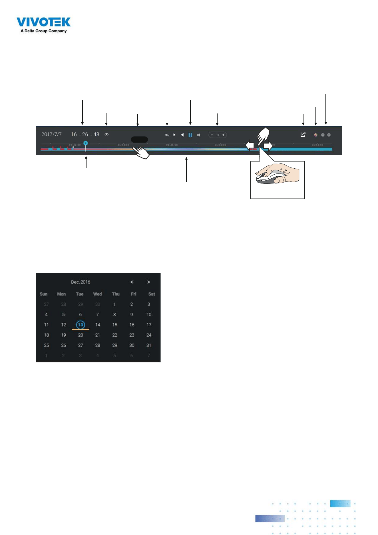
3. Timeline Panel: This panel appears when Playback is initiated.
Starting from left to right, timeline control functions will be described as follolws:
1. Time Search: Click on the current date to open a calendar. If you want to review videos
recorded in another day, select it from the calendar.
Timescale is adjustable (minutes, hours, days, to a max. of 3 days) so you can easily find
the required time period and begin playback from that point.
Histogram
Adjustment
Export
Speed Control
Playback Timeline & Histogram
Playhead
Synchronous
Playback Control Buon
Time Search
Events
Highlights
06:44:23
Mouse-over
indicator
Return to Live
Drag to move along
meline
Blue: days with recordings.
Orange bottom line: Today.
White: days with no recordings.
7676
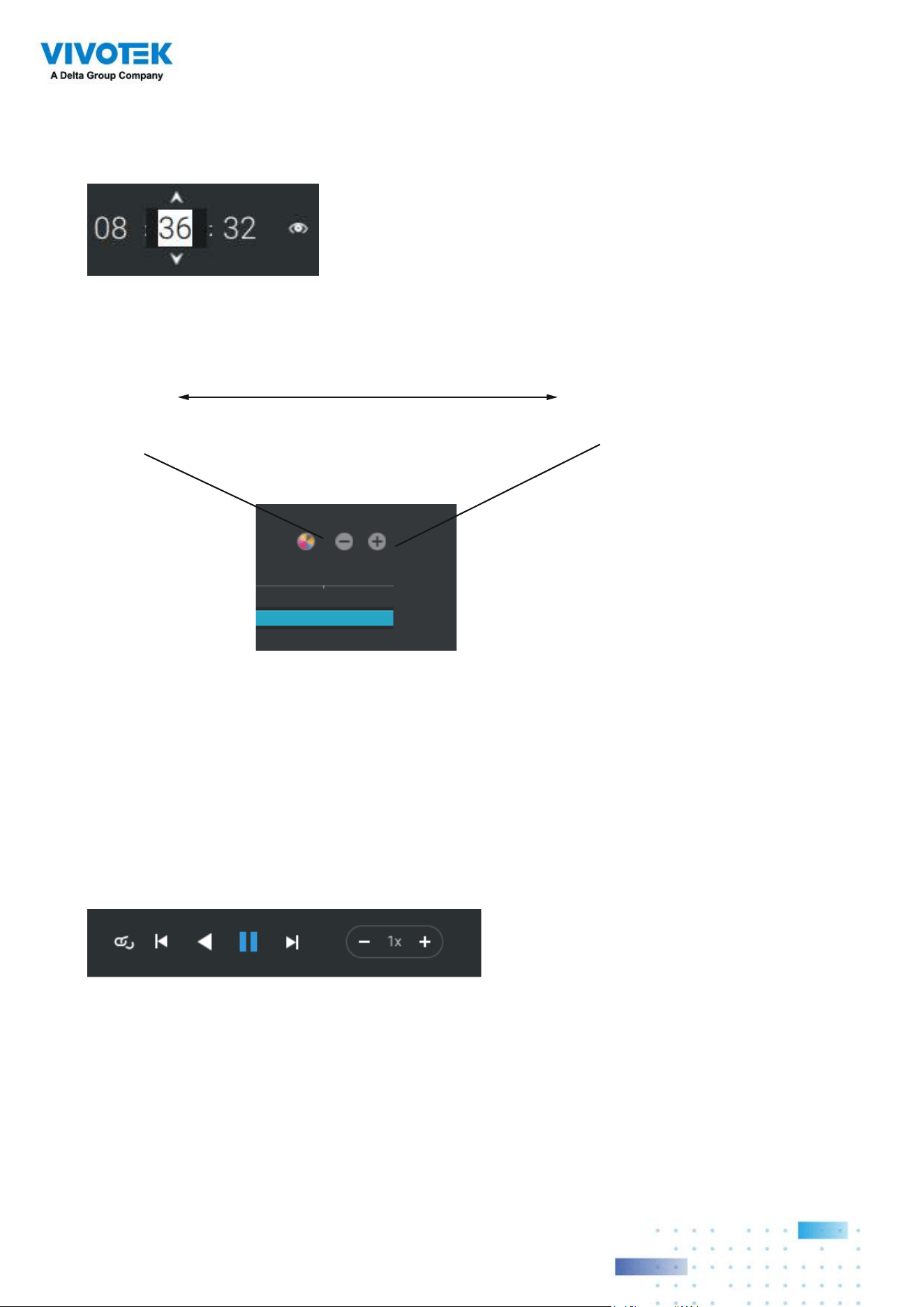
Click on the current time. You can use the arrow buttons to change the time you wish to
playback, or simply enter a preferred number. You can also pull the playhead along the
timeline.
Timeline magnification levels: The default time span is 6 hours. You can change the
magnification level for easier browsing. Click the Zoom in and Zoom out buttons to change
the timeline time span. The configurable time spans are shown below:
3 days, 1 day, 12hr, 6hr, 3hr, 1hr, 12mins, 1 min
2. Playback control:
From left to right,
2-1. Synchronous play: This lets all cameras in the same view to playback video of the
same point in time. If you perform synchronous playback on a multi-cell view, your
computer can be stressed. It is recommended you create a new view with a 2x2 layout,
select and insert camera views into it, and begin the Synchronous playback.
2-2. Frame by frame buttons: Click to move forward or backward to flick through the video
frames. This may only display the I-frames.
2-3. Forward playback and reverse playback: Click to view the video in the forward or
reverse playback manner.
7777
2-4. Speed selector: The selectable speed ranges from 1/64x to 64x.
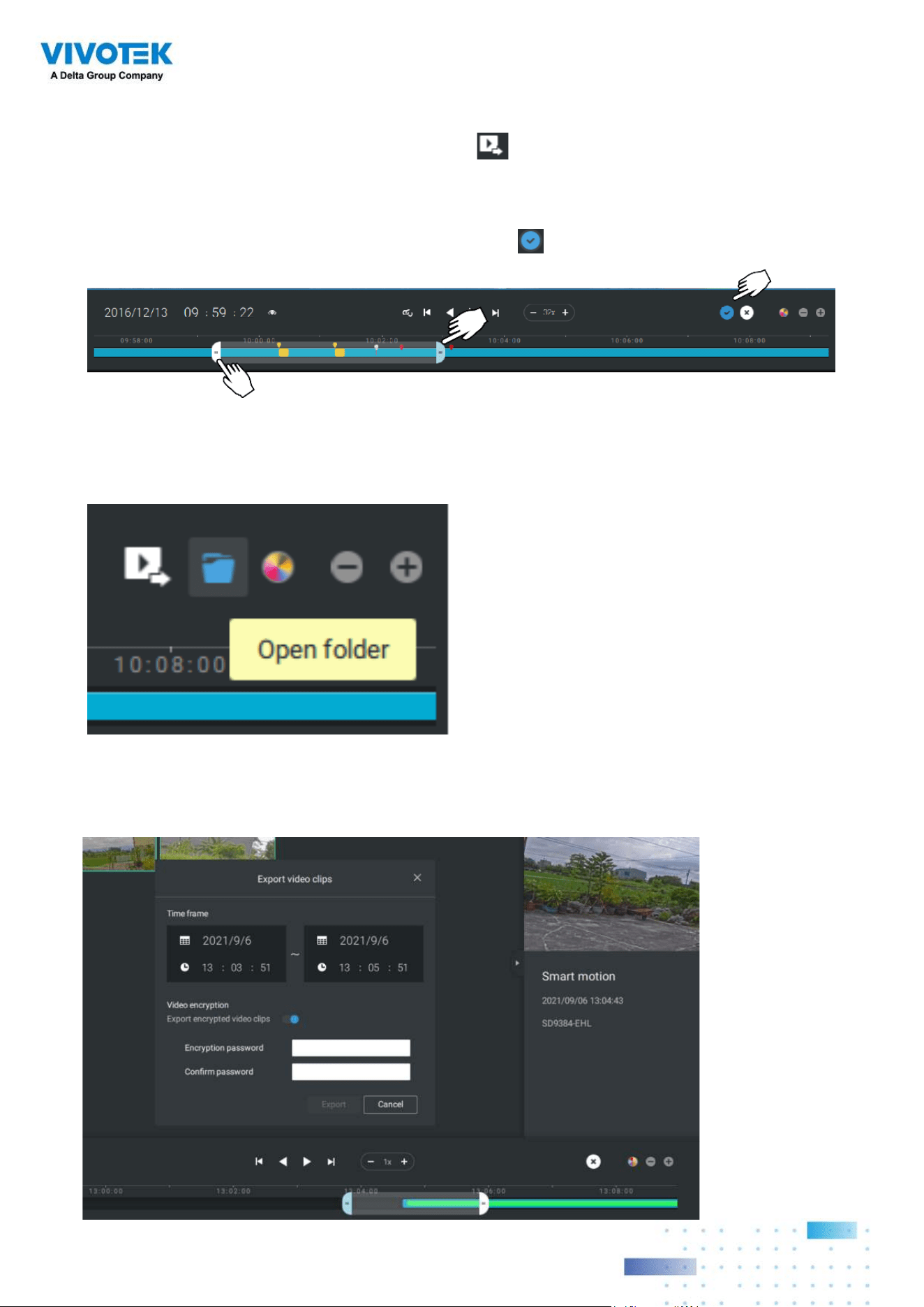
3. Export Clips: Click the Export Clips button
. A range selector will appear. Pull the
ends to include the time span you want to export. Note that each end of the selector,
when clicked and selected, will turn white, and its location on the timescale is shown on
the time line. When done, click the Start to export
button.
Depending on the length of video clips to export, it may take minutes to export. When the
export is completed, a shortcut to the exported clips is shown. You may then open the
folder where the clips are located.
When you export a video, you can assign a password for the encrypted video. Once
encrypted, you cannot play the video using ordinary video players. You can only play the
video using VSS standalone player after you enter the correct password.
7878
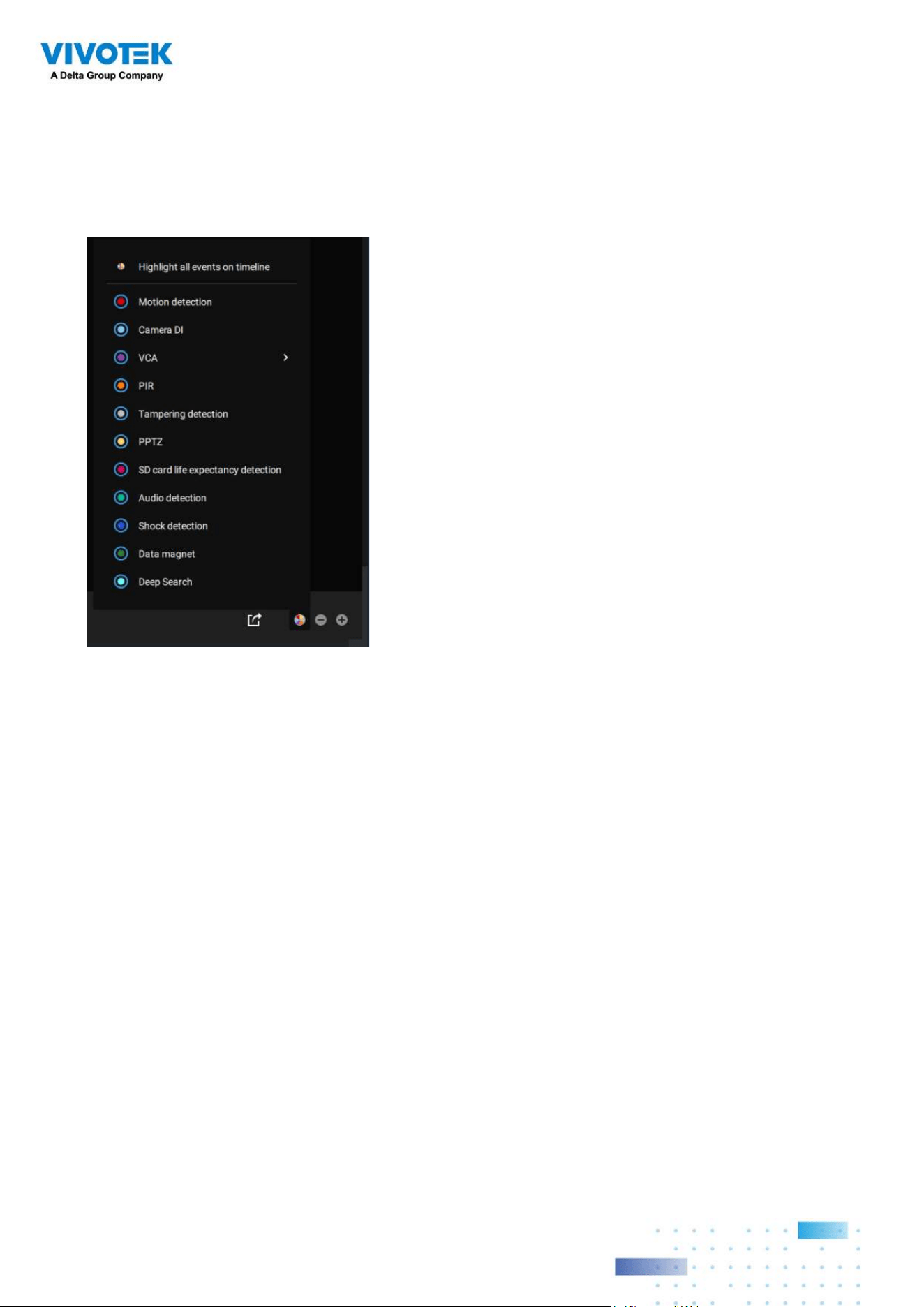
Event Highlights on timeline: Select one or all of the event types to display event tags on
the timeline that match those have occurred in the past.
Note that on the VIVOTEK's Linux-based NVR, the timeline will display the occurrence of
an event for a length of 10 seconds since its occurrence.
7979
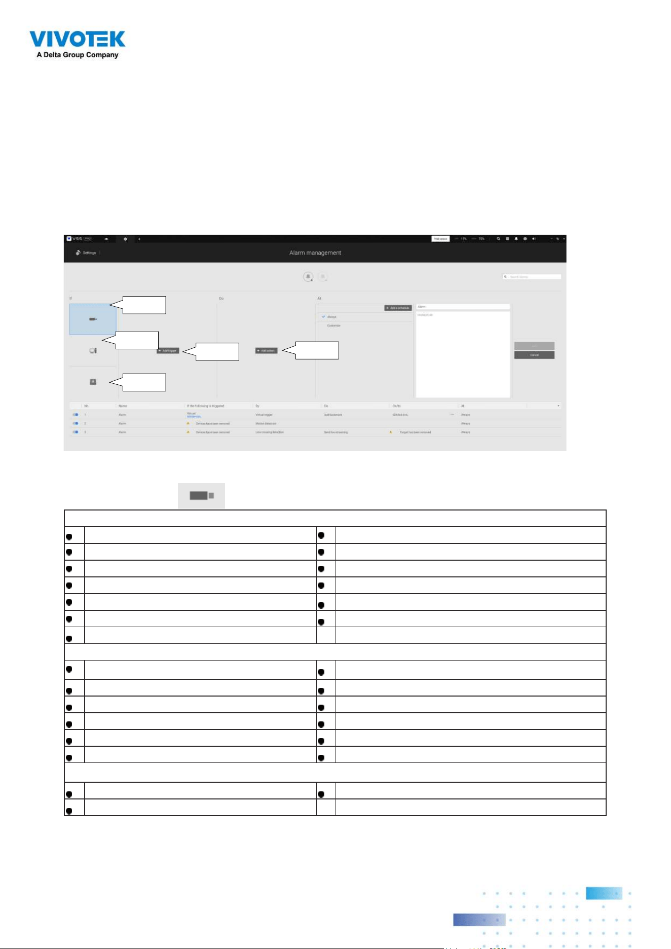
2-14. Alarm
The Alarms can be configured to perform a series of actions when different events occur.
Alarms can be used to automatically react to possible threats. For example, the VSS server
can start a recording or send an Email notification when Motion detection is triggered.
A wide variety of triggering conditions can be applied, including:
1. Camera triggers
General
Motion detection IR (Infrared)
Camera DI PIR (Passive Infrared)
Camera DO Tampering detection
Temperature Stop recording
Recording error Audio detection
Video loss (Video server only) Shock detection
SD card life expectancy detection
Video Content Analysis
Line crossing (VCA) Intrusion detection
Loitering detection Face detection
Missing object detection Unattended object detection
Crowd detection Smart tracking
Zone detection People running detection
Parking Violation detection Restricted Zone detection
Trend Micro IoT Security
Brute force attack Cyber attack
Quarantine event
Camera
Server
I/O box &
external
Select
triggers
Select
actions
8080
Note that some of the triggers require that you open a web console to individual cameras. For
example, VCA and Motion detection windows have to be manually configured on each camera
before they can be configured in the Alarm settings.
If a triggering condition is associated with event recording, an event prompt will pop up on
the screen when a triggering condition is met. For example, the number of people exceeds
a preset threshold in a Crowd Detection configuration. The sample prompt is shown below.
The related footage can be played back by clicking on the event entry.
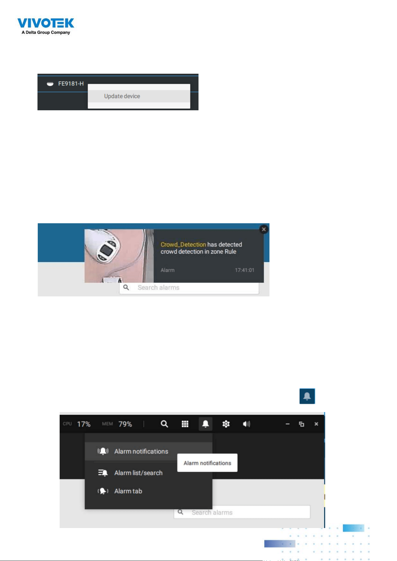
If you select a trigger and you cannot find a corresponding device, you need to open a web
console to that device. Make sure the corresponding VADP is running. Open the VSS device
tree, right-click on the device to perform a manual refresh "Update device" to acquire the
lastest configuration update.
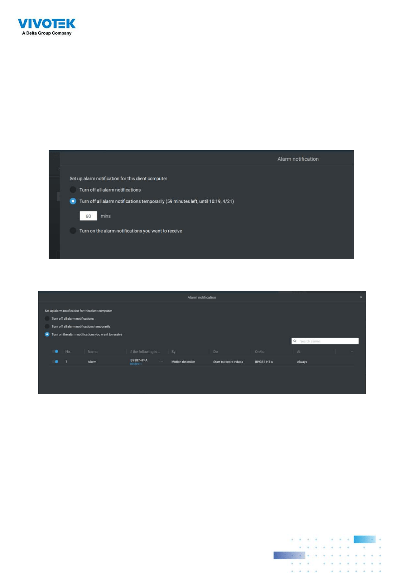
The alarm notification can be turned off by clicking on the Alarm tab. You can enter
the time span when you do not want to receive notifications and the notifications will
automatically turn on after the time span. Enter the number in the mins field. The max.
time span is 9,999 minutes.
The notification configuration is kept on the client computer.
When the Alarm notification is turned off, the Alarm tab icon is greyed out .
8181
Note that the default for the alarm notification is "Turn on the alarm notification you want
to receive." If you turn off the alarm notification, you need to re-activate it after you turn off
the notification the first time.
Individual VSS clients can configure which kinds of alarms can be delivered to them by
selecting the alarm types listed in "Turn on the notifications you want to receive." When the
individual alarms are turned off, the following client-side alarm actions will be disabled on
the client computers:
1. Notification.
2. Send live streaming.
3. Go to E-map.
4. Sound the alarm.

8282
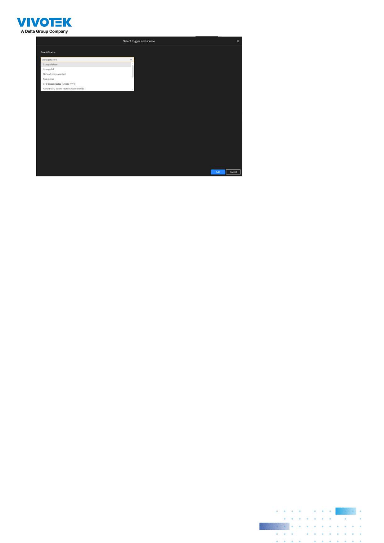
2. Server and NVR triggers
Network disconnected These can be used to send maintenance notifications.
Storage failure
Storage full
Fan status
GPS disconnected
(Mobile NVR)
The GPS and G-sensor related options apply to the Mobile
NVR that comes with the GPS and G-sensor. GPS can be
used to track the speed and location of a vehicle, while the
G-sensor can be used to detect abnormal impact.
Abnormal G-sensor
motion (Mobile NVR)
Speeding (Mobile NVR)
Number of remaining
people
For VCA-capable cameras, the alarm can be triggered when
the number of people staying within a specific area has
exceeded the preset threshold. For example, when too many
people are waiting in line in front of a cashier.
This function requires appropriate configuration on the
counting camera(s).
Brute force attack (Trend
Micro IoT)
These can be configured as alarm triggers to notify the
administrator that malicious attacks have occurred. Note
that these triggers are available with NVRs that come with
the protection of Trend Micro IoT packages.
Cyber attack (Trend Micro
IoT)
Quarantine event (Trend
Micro IoT)
* Note that you should use the pull-down menu to select a triggering condition, and then
click to select a mobile NVR.
8383
Note that the alarms will be received into the Alarm list window. The previous Alarm Search
window is replaced by the Alarm list function.
The Alarm tab window is used to display the live video stream when an alarm is triggered,
and its responding action is configured as "Send live streaming."
8484
For I/O box configuration, please refer to the I/O Box page.
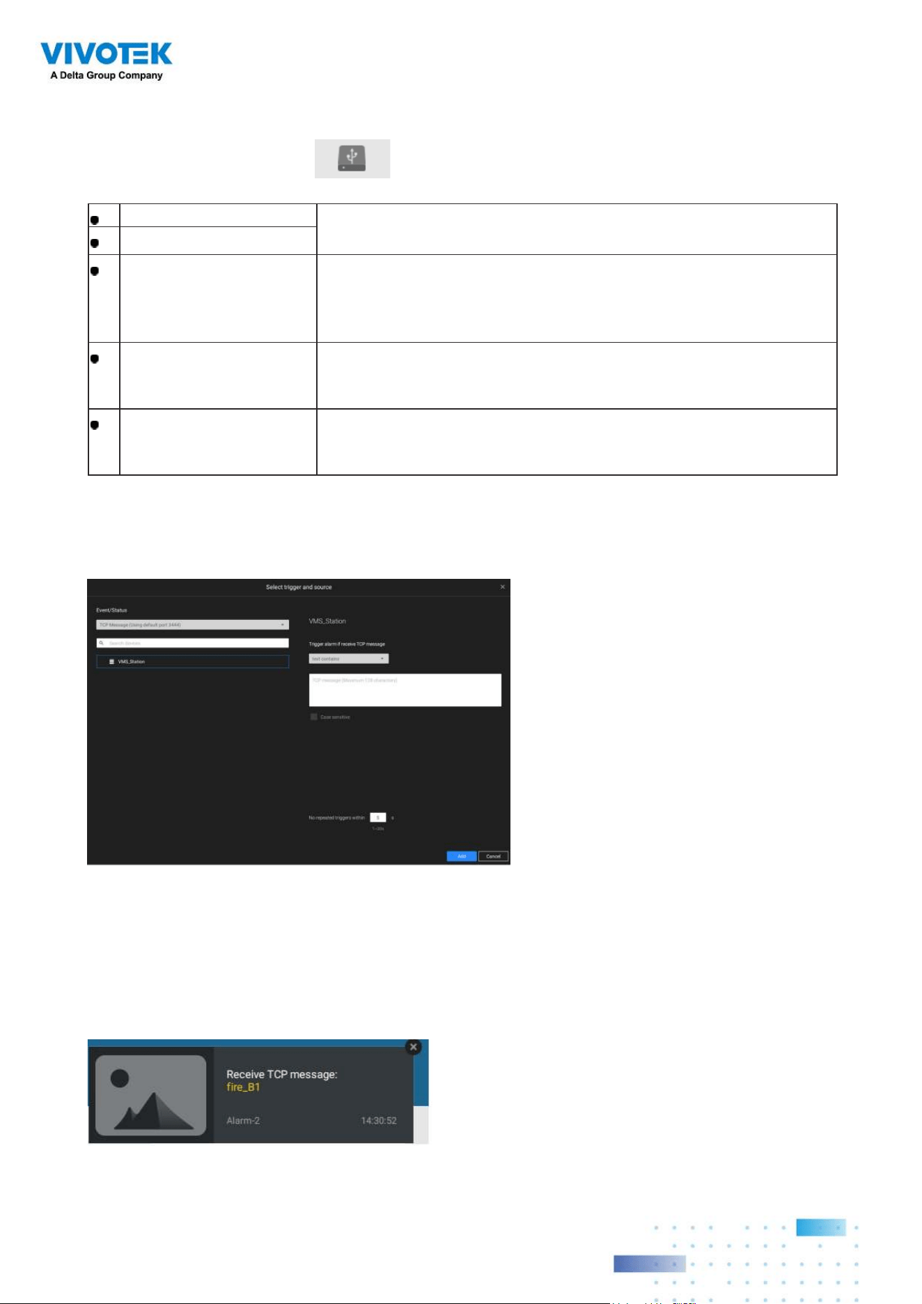
3. I/O box and TCP triggers
DI/DO Device DI This applies when an external I/O box is applied, e.g.,
Advantech's ADAM I/O box.
DI/DO Device DO
TCP Message TCP message comes from the peer VSS servers or external
sources (such as an access control system) via the analysis
of received TCP message over the 3444 port. This is a paid
feature.
Data Magnet Triggering conditions can be acquiring data from 3rd-party
software, such as the character height, image width, list, list
name, country, from an LPR software, etc.
Virtual trigger A virtual trigger allows users to create a button on live view
to trigger Alarm actions, e.g., go to a camera preset, add
bookmark, play an audio file, send HTTP requests, etc.
To configure a TCP message trigger,
Select TCP message as a trigger type, and enter a description, such as a short term, for
VSS to listen and analyze data packages.
You can use Telnet to send a small amount of data matching the term you entered in the
TCP message configuration window. A TCP message event will be triggered, and you
should see the event prompt as follows.
Below are the messaging parameters:
1. text contains: Messages will be
received if some of the textual
messages match the keywords.
2.
text matches: Textual messages
must be exactly identical.
3.
Case sensitive: The upper or lower
cases letters used in the messages
must match within the messages.
8585
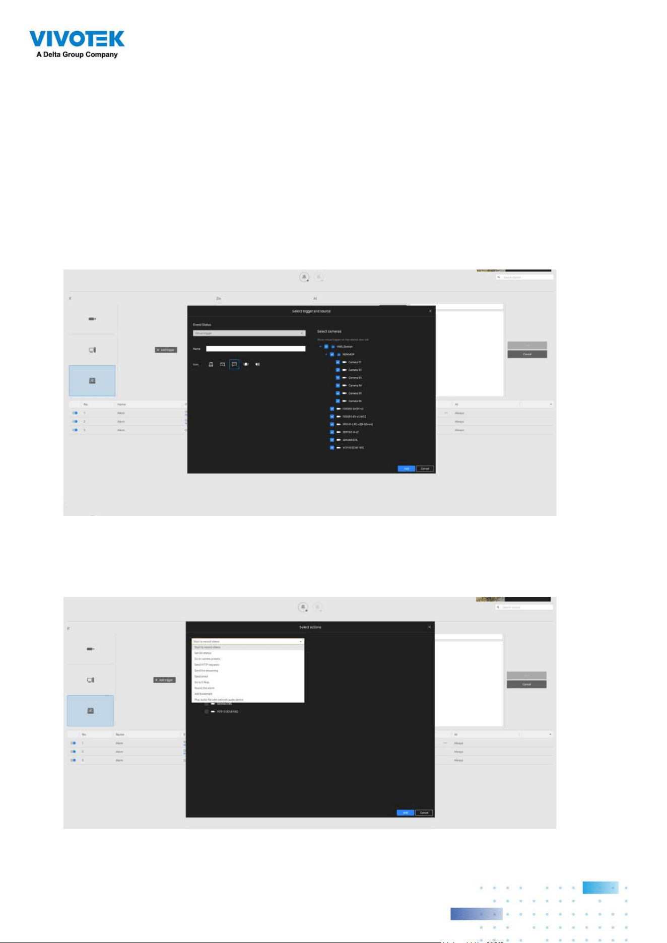
To configure a Virtual trigger,
Go to Settings > Alarm > Add alarm.
Select the External device event, and then click on the Add trigger button.
The Select trigger and source window will prompt.
Virtual triggers have the following benefits:
1. More operation control, e.g., got to camera preset, add bookmark, play audio file with
netwok audio devices.
2. Integrating 3rd-party systems and devices, using the Send HTTP requests, Set DO status
commands.
Select the alarm action.
8686
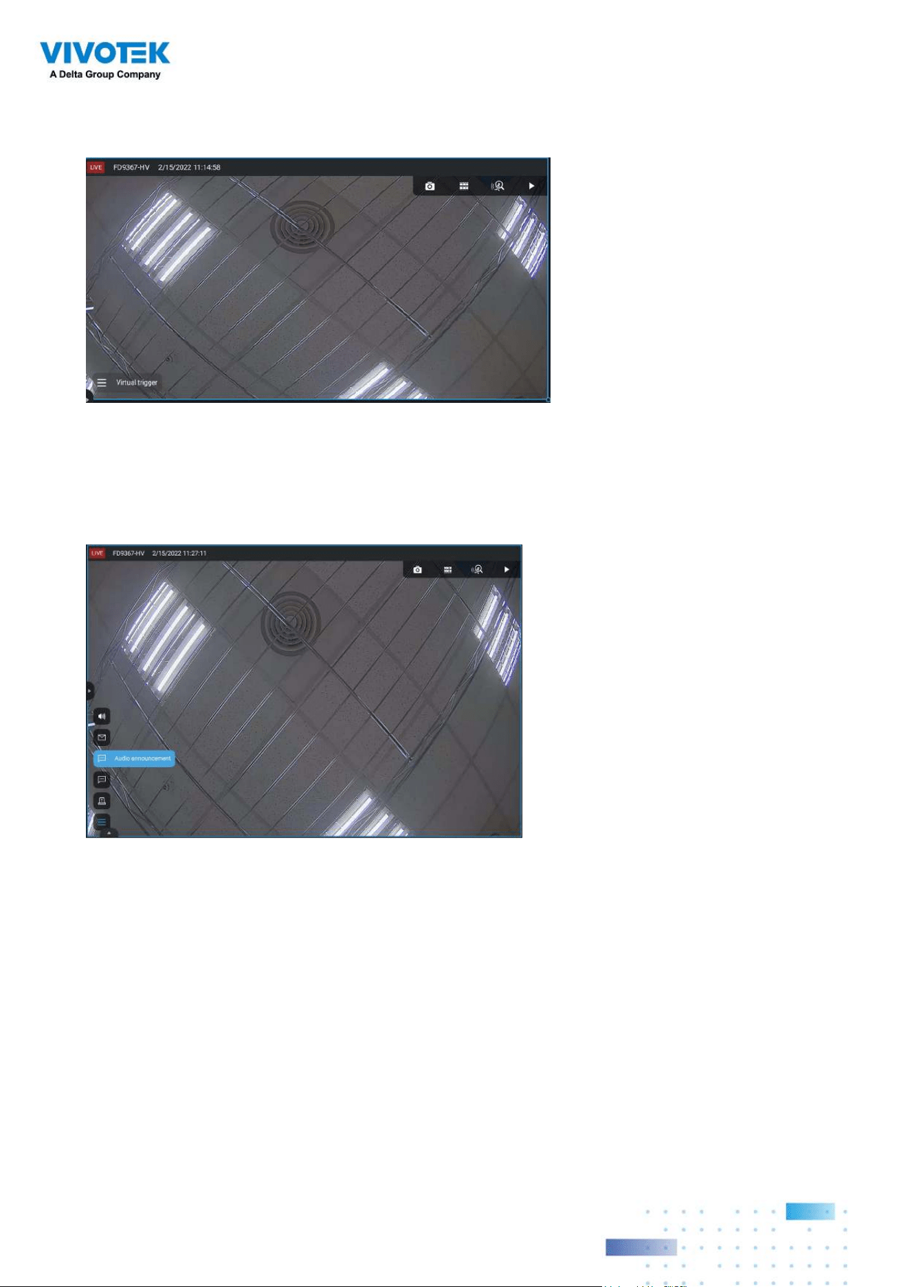
With a pre-configured virtual trigger, a trigger button appears on the live view.
When activated, all of virtual trigger buttons will appear allowing you to perform the
associated actions.
8787
The available actions include:
Start to record video Send HTTP requests
Set DO status Send live streaming
Go to camera presets Send email
Go to E-map Sound the alarm
Add bookmark Play audio file with network audio device
The
Start to record video will record a video clip of the length of 10 seconds (default) on
the occurrence of an event. The event recording pre / post event time is configurable.
Except for Stop recording, all the other triggering conditions can be associated with this
action.
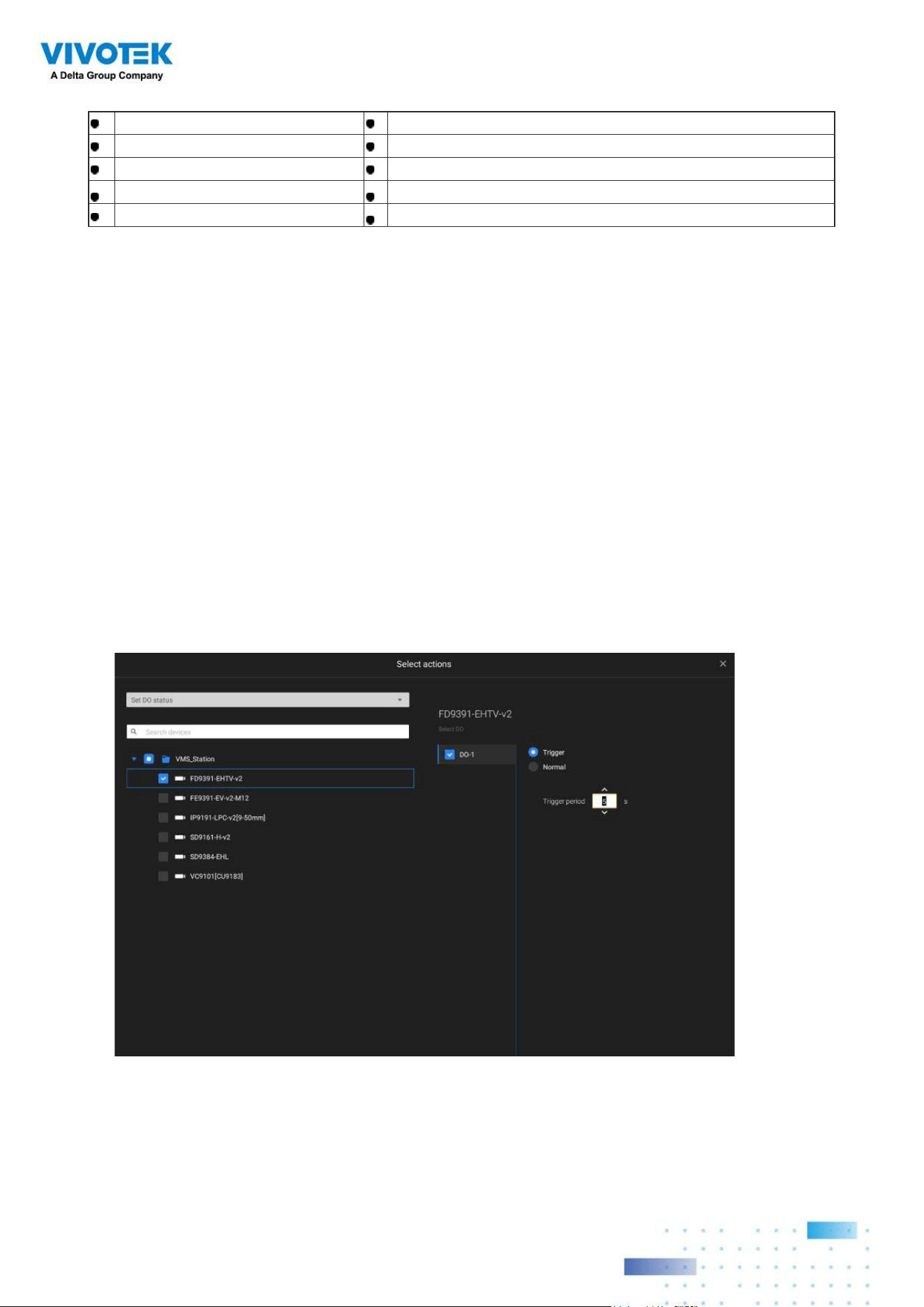
The Set DO status will activate a DO connection. For example, to light an illuminator or
sound an alarm.
You can select a camera, and its DO pins will appear on the right. You can configure the
duration of the DO trigger, e.g., 15 seconds.
If no Trigger period is configured and when there are multiple instances of DO trigger,
administration troubles may occur. Use the arrow marks to configure a trigger period. You
may also manually enter a number.
8888
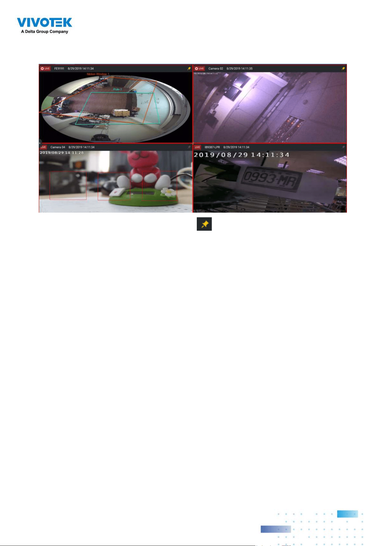
The Send live streaming action will bring up a video prompt to the Alarm tab window,
showing the realtime video feed from a specific camera.
The Go to camera presets requires you to configure preset points on a PTZ camera before
the Alarm configuration, such as a speed dome. Once triggered, the PTZ camera lens will
move to a preset position.
The VSS server automatically disables unavailable options. For example, when the DO
option is selected, the cameras that do not support DO connections will be hidden.
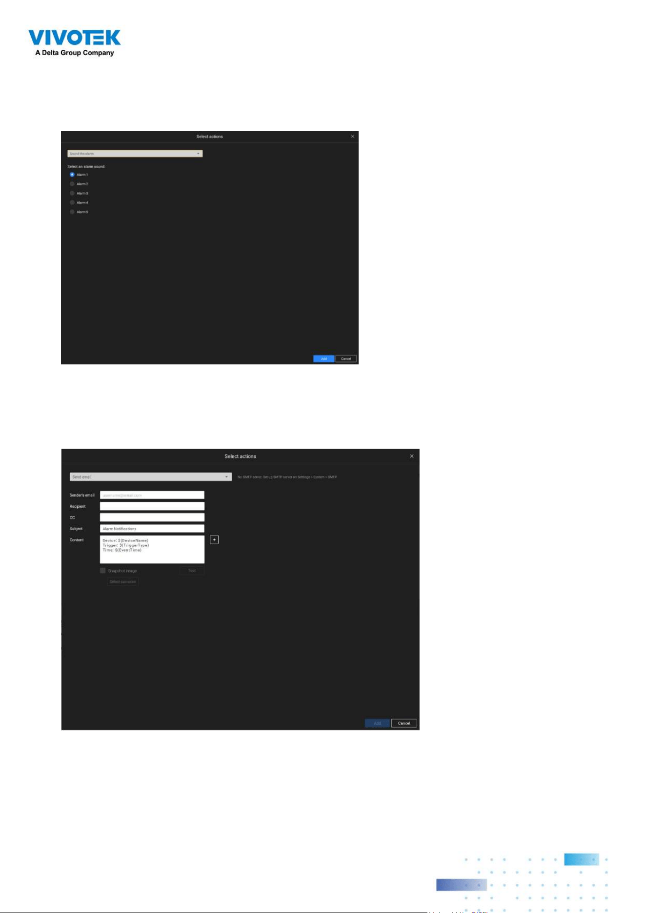
The Send email opens a configuration page where you should enter valid email addresses
as sender and recipients. It is required that you configure an SMTP server for mail delivery
in Settings > SMTP. Enter Subject and contents. Select the checkbox for including a
snapshot of the event. When done, click Add to enable the action.
The Go to E-map opens a pre-configured E-map of where the triggering condition occurs.
The user can then click on the camera icon on the E-map for an instant viewing.
The Add bookmark function saves a video clip of a 10-seconds length. Once triggered, you
can open a new view tab > Search > Bookmark search to find the existing bookmarks. The
bookmarked video clips will not be recycled during the storage cleaning cycles.
8989
The Sound the alarm action provides 5 alarm sounds that will be sounded on the VSS client
or server. Your VSS client or server should have speakers for playing the audible alarm.
A reacheable Mail server and Email accounts must be provided before you can apply the
settings.
9090
On the Schedule page, you can select to activate or de-activate alarm triggers throughout a
specific timeline. For example, in some situations you can disable the alarm triggers during
the office hours, and choose to enable the triggers only during the off-office hours.
Click on any of the options on the Schedule panel for the alarm to take effect: Customize,
Always, or Add a schedule.
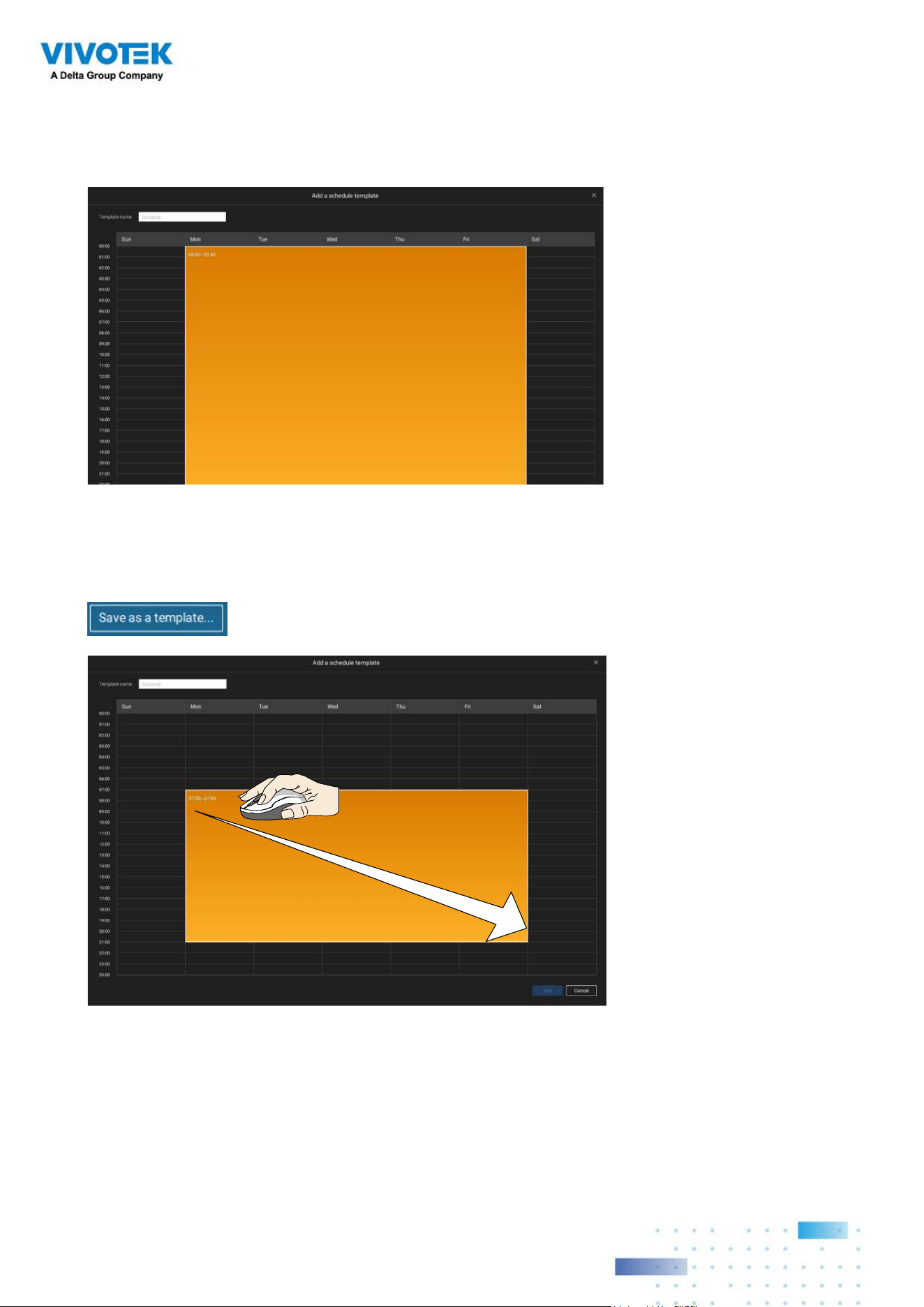
You can manually create a effective time template using the New template
button.
9191
Click and hold down on the time cells, and drag the mouse to include the time span of your
preferrence. The minimum selectable unit is half an hour. You can select multiple time
spans on the template. Enter a name for the template, and click Add to save your template.
The same configuraion window apply to both the Schedule template and the customize
schedule windows.
Make sure a Schedule mode is selected when you leave this configuration step.
Enter a name and instructions for users to follow, and then click Add to complete the Alarm
setting.
All configured alarms will be listed on the Alarm settings page.
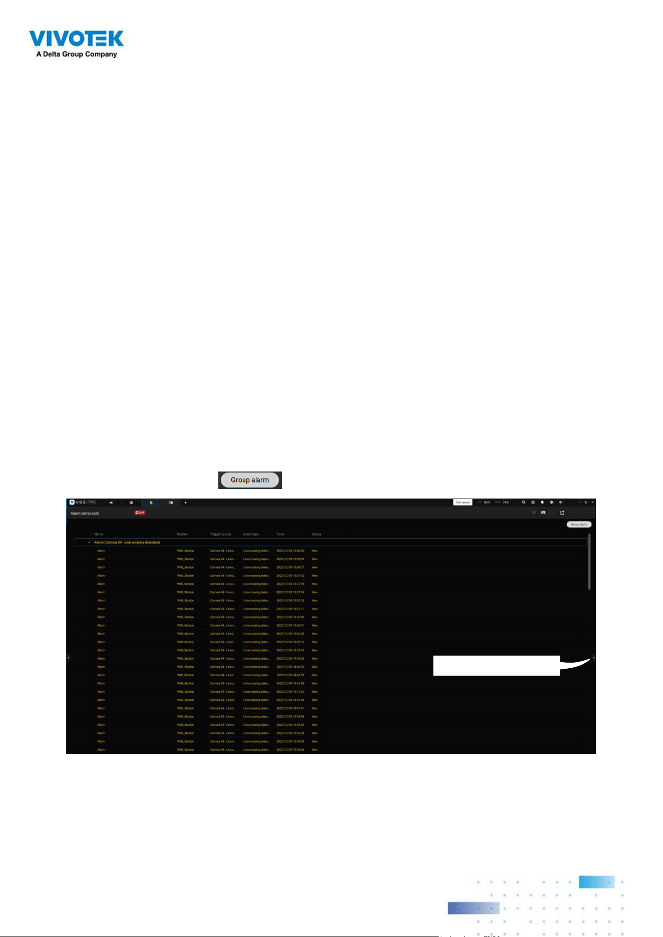
Group Alarm
Multiple triggered alarms can be presented as group alarms. Alarms triggered by the same
event type, and by the same camera can be grouped together. In this way, multiple similar
alarms can be listed under one entry.
On the alarm list, click the
button to display the alarm group.
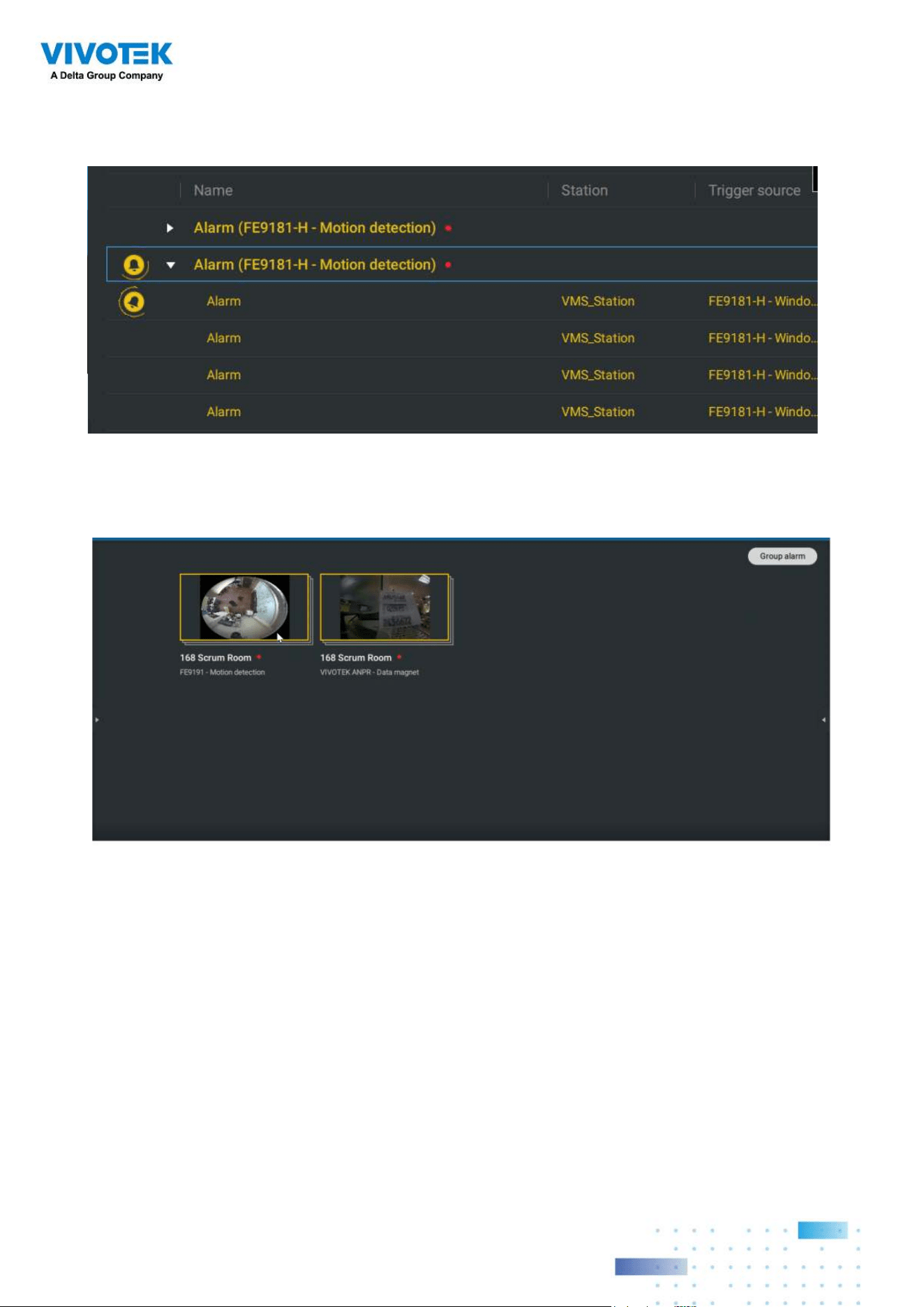
Click to reveal the video viewing panel.
In the list mode, you can expand the right-hand-side panel. The video of the latest alarm
will display.
9292
The same applies to the thumbnail view. To leave the group alarm view, click the Group
alarm button again.
When the alarm-triggered action is configured as sounded alarm, you can mute all alarms
in the group by clicking the alarm sound icon.
9393
When the alarm action is set to "Send live streaming," the videos coming from the same
camera will occupy only one view cell.
In the Alarm tab window, use the thumbtack button to freeze the current screen. If
thumbtacked, the other incoming alarms will not affect the current screen.
On arrival, the latest alarm will display with a blinking red frame. A selected view cell will
display with a yellow frame.
9494
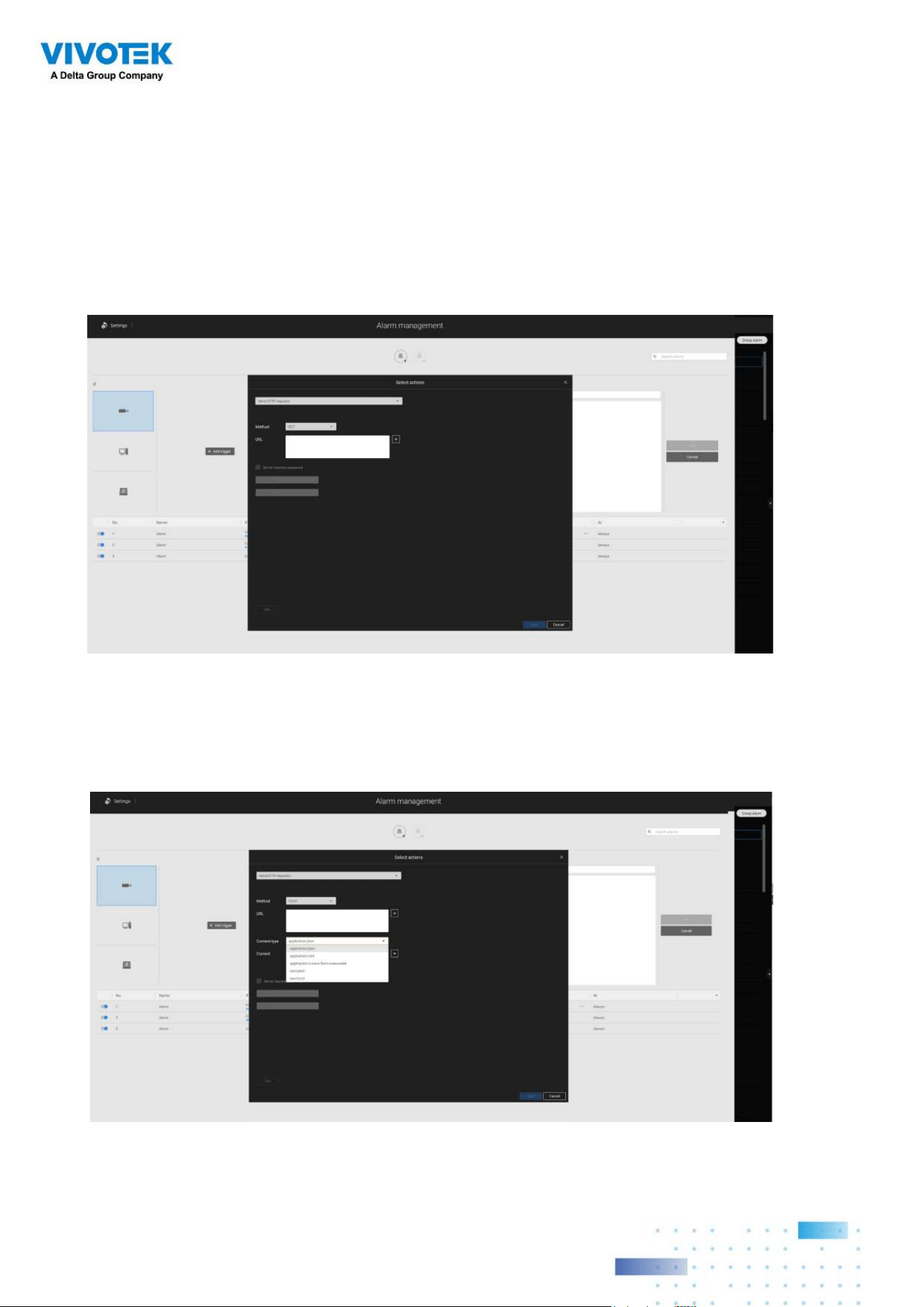
Configuring Send HTTP requests
When configured, the server will send an HTTP request protocol to a 3rd-party device or
application. The HTTP request supports GET and POST commands.
The GET method is to request data from a specified resource.
The POST method is used to send data to a server to create or update a resource.
Below is a screen for setting the GET command. Enter the target resource's URL address.
Below is a screen for setting the POST command. Enter the target resource's URL address,
the content, and select the content type. If the need should arise for more content types,
you can contact VIVOTEK's technical support.
9595
2-15. Search Panel
The Search panel is accessed via the Search button. 4 key functions are provided:
Bookmark search, Deep serach, Event search, and Smart search.
1. Search by Bookmark:
Bookmarks are manually created when users review recorded
videos in the Playback mode. Each bookmark comes as a 10-second video clip.
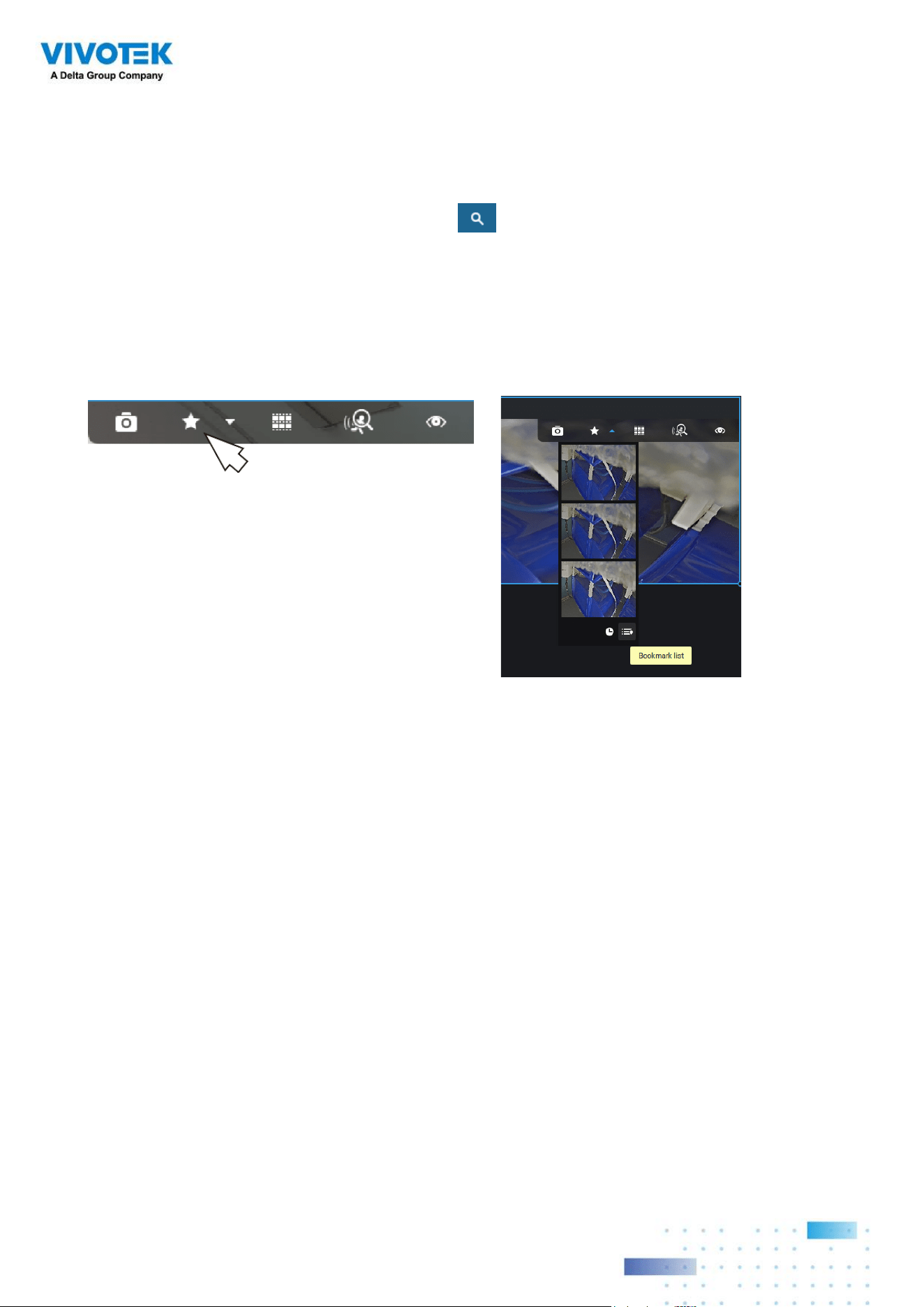
9696
In the Bookmark search panel,
Click the Bookmark search
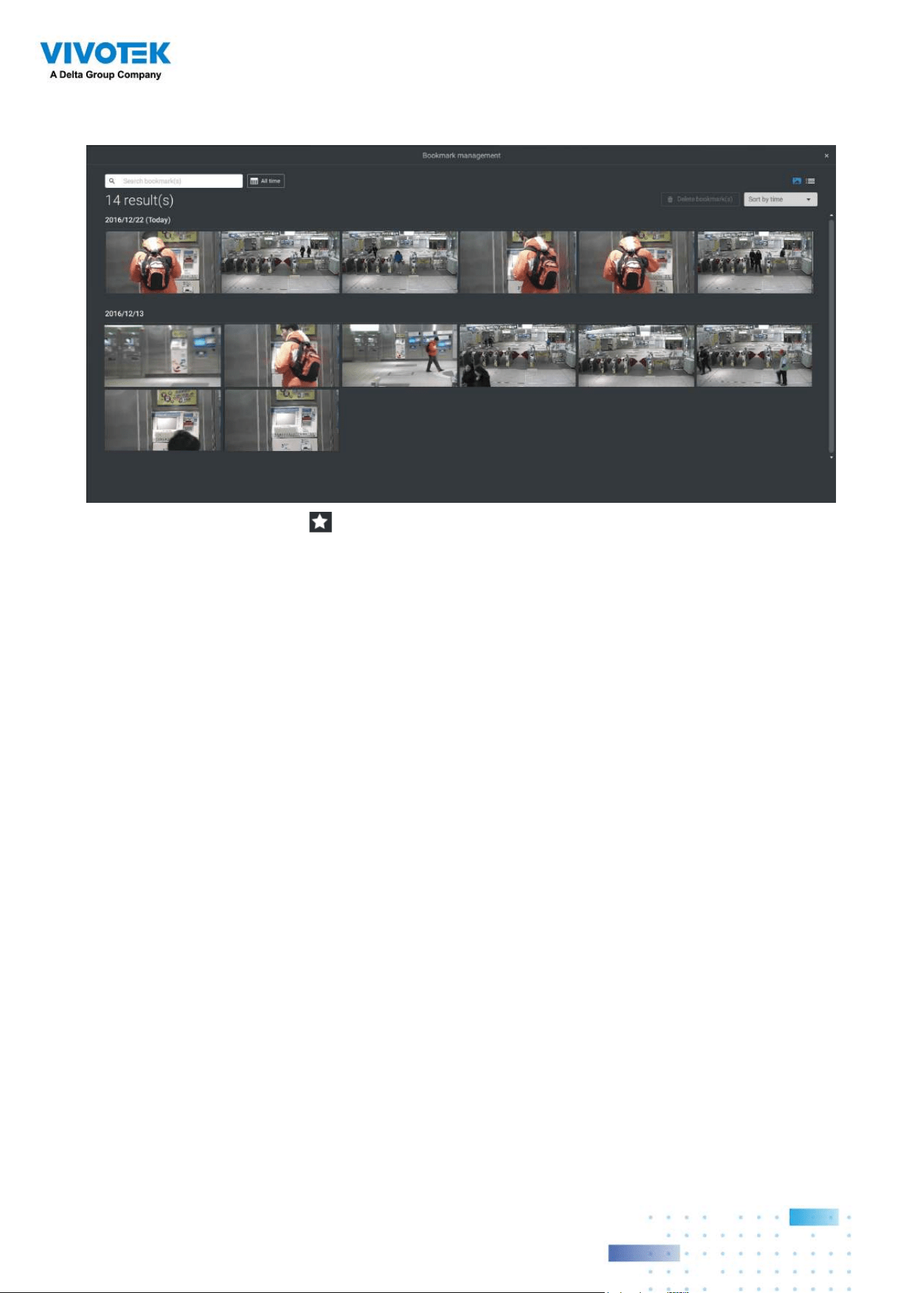
button. The Bookmark Management window will prompt.
All existing bookmarks will be listed with thumbnails.
a. On this window, you can specify a range of time during which the video streams were
recorded and its points in time when bookmarked.
b. You can then click on a bookmark to display the short video clip extracted from within
the recorded video. The default is 10 seconds.
c. To remove an existing bookmark, left-click to select an entry, and then click the Delete
bookmark(s) button. Bookmarks will be indicated as "Invalid" if the videos where the
bookmarks were appended were erased, e.g., when the original recording was erased by
cyclic recording.
d. Currently you can search for bookmarks using the name of the camera.
e. You can also select the display types for the bookmark search in either the thumbnails
or list mode.

9797
2-16. Smart search
The Smart search function enables a quick glimpse of activities occurred within a user-
configurable detection area from the recorded videos. Smart search is available in both the
Liveview and Playback mode.
Click to select a camera view cell. Click on the
Smart search button to enter the Smart
search window.
There are two Smart Search modes: Smart search II and Smart search I. The Smart search
II applies to the recordings of the cameras that come with the Smart Motion, and other
VCA capabilities. There are two kinds of metadata polled from camera VCA packages:
1. Motion cell: Pixel-based information. The search results will include all moving
objects in the scene.
2. Object information: Human-based information. If People or Vehicle detection is
selected, only objects detected as human or vehicle will be displayed as the search
results.
Please refer to VIVOTEK's website pages that are related to the Smart motion and Smart
VCA features for the supported cameras.
Note that not all cameras support the latest vehicle detection feature.
9898
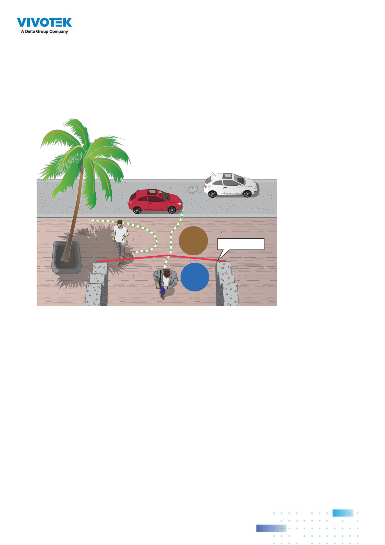
Line Crossing Detection
The Line Crossing detection detects one or multiple persons crossing a virtual trip-wire.
The trafc direction can be assigned on screen for persons passing the line in one specic
direction or in both directions.
Out
In
Detection line
The applicable scenarios of this feature can be:
* Detects someone who enters a drive way, entrance, or exit through the virtual line.
* Detects and triggers an alarm in a predetermined direction.
* The detection line can be used as a fence boundary to know if someone has crossed the
articulated line around a perimeter.
Below are short description for the Line Crossing, Loitering, and Intrusion detection
functionality:
9999
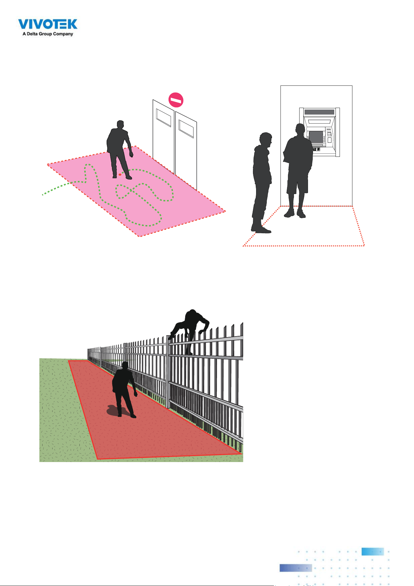
Loitering Detection
The Loitering detection can be used to detect a person or a group of people lingering in an
area for longer than a preset time threshold.
ATM
Intrusion Detection
VIVOTEK Intrusion Detection can be used to detect people entering or leaving a virtual
area in the camera eld of view.
Alerted zone
The applicable scenarios of this feature can be:
* Detects when a person enters a bank vault or school after the ofce hours.
* Detects when a person leaves an emergency exit or fire escape, or any place that is
normally forbidden from access.
100100
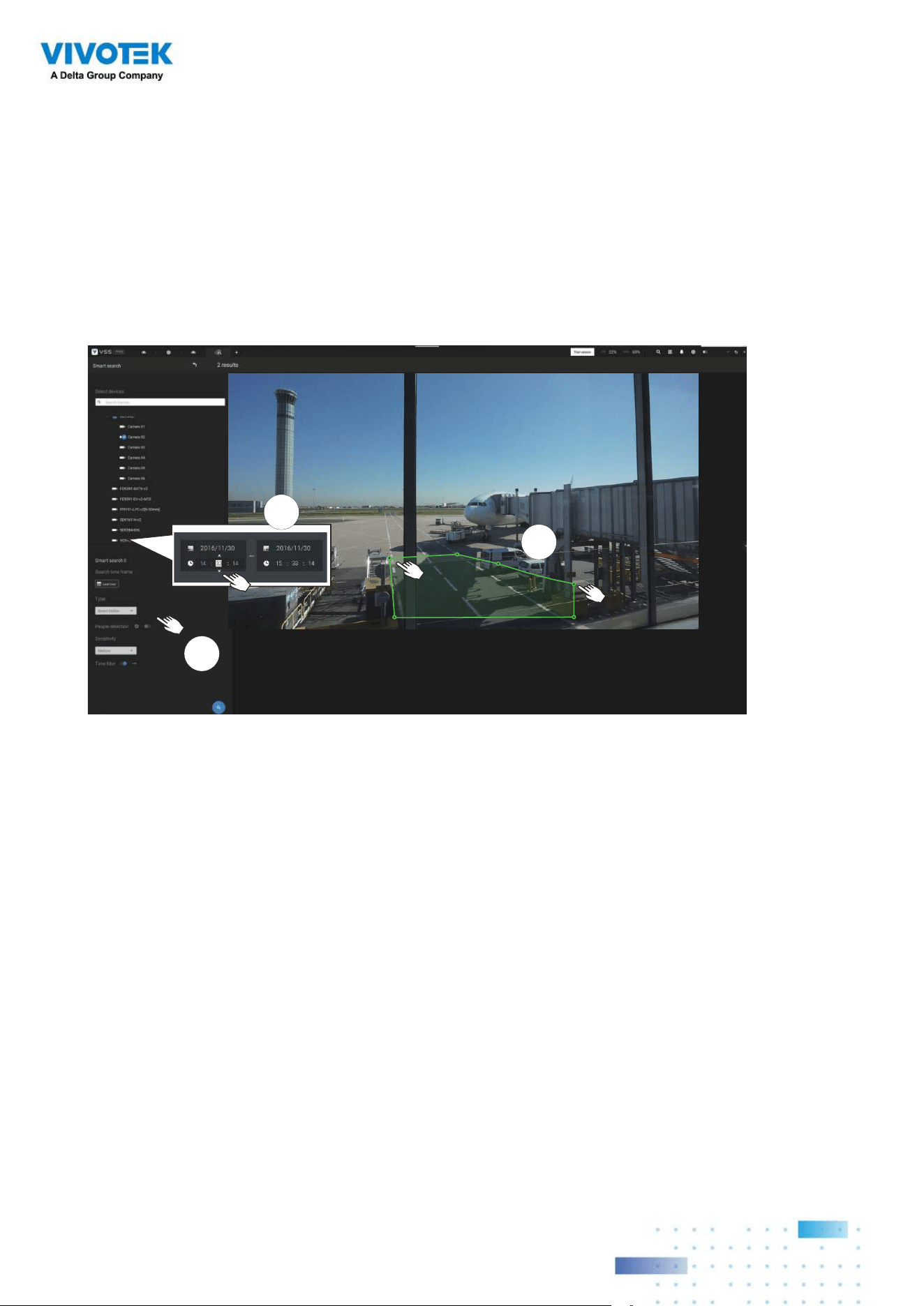
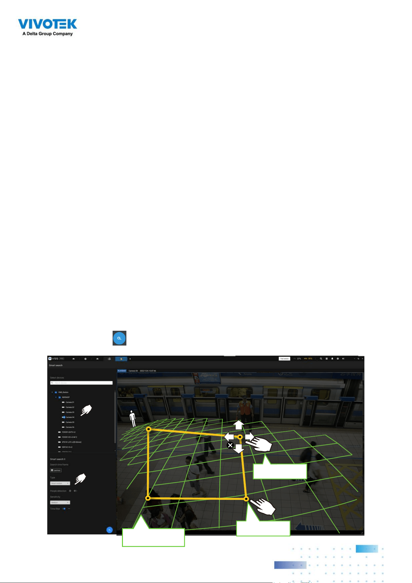
1
2
3
To use Smart search,
1. Use the date and time selectors to specify a time span on which to perform the Smart
search.
2. Select a Type (Smart motion, Line crossing, Loitering, or Intrusion). Selecting Line
crossing detection may require you to adjust the position of the detection line.
3. There are different parameters for each detection Type. Refer to each VCA feature's
documentation for details. You can tune the parameters for each VCA feature. See next
page for the configurable parameters.
4. You can draw one polygon with multiple mouse clicks to include areas where activities
of your interest have occurred. You can draw one or more cross lines for Cross line
detection. Double-click to close a polygon.
5. Click the Search button.
101101
Search parameters:
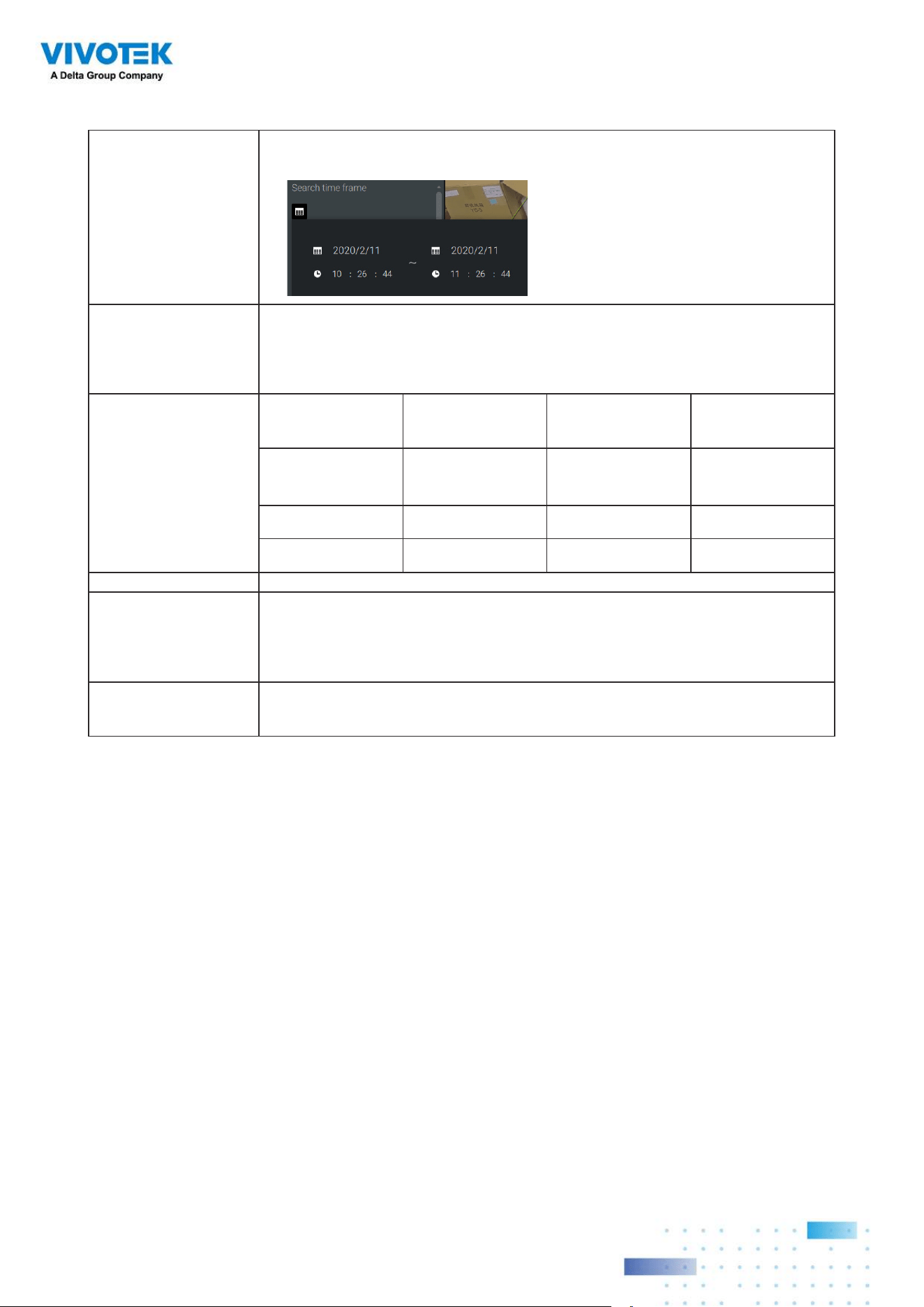
Search time frame Use the calendar tool pane to specify the time span within which the
activities in scene will be searched.
Type If the selected camera supports multiple Smart VCA detection features, the
supported types will be listed:
Smart motion, Line crossing, Loitering, or Intrusion.
Parameters
(determined by Type)
Smart motion Line crossing Loitering Intrusion
People detection* People walking
direction
Stay time Direction:
Into the zone /
Leaving the zone
Sensitivity**
Time lter
* People or Vehicle
detection
People or Vehicle detection enables the display of the alarms detected via the
human or vehicle silhouettes algorithm. This can be used to lter out video
analytics alarms that are not related to human or vehicle activities, such as swaying
vegetation, or small animals.
** Sensitivity Congure the sensitivity for the detection of the activities in scene. Low for near
scene, high sensitivity for long distance scenes.
Note that different cameras support different VCA functions. Please refer to the
documentation for Smart VCA or Smart tracking features, such as the Smart VCA User
Guide.
IMPORTANT:
Running Smart Search II requires cameras that support the following:
1. Smart motion.
2. Firmware version above 0113d, 0117b or 0100i (Authwebsocket support is needed)
3. VCA package version above 6.1.3a.
102102
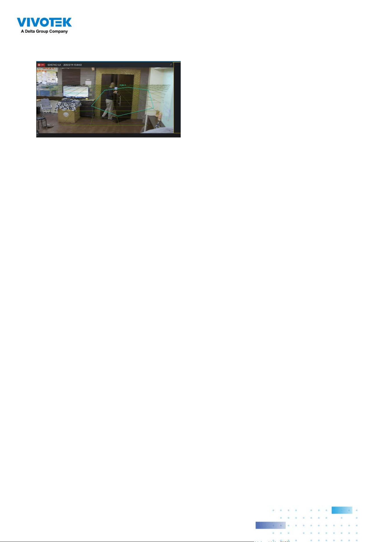
Green horizontal grid
as People detection area
Click to create.
Drag to change shape
If your camera supports Smart VCA features, you can manually create detection rules
on the configuration screen. Note that you may not need to do this if you have already
configured detection rules on the camera.
1. Select a VCA camera.
2. Select a VCA type from the pull-down list: Smart Motion, Line crossing, Loitering, or
Intrusion. For a camera that supports only one VCA feature, such as Smart tracking on a
speed dome, there is no "type" option.
3. You can then draw a detection zone, or detection line on the screen.
4. Select a time frame using the calendar tool.
5. Select to enable or disable the People detection feature and configure the Time filter, or
other parameters.
6. Click the Search button.
In most cases, it is presumed that you have configured VCA detection zones and detection
rules such as lines to detect people crossing. You can also configure a detection zone or
lines on the VSS server and then search for the detection results from the recorded videos.
NOTE:
* Smart search II supports people detection whether the camera comes with a Smart
motion license or not. However, the Line crossing, Loitering, Intrusion features will not be
available.
* With a valid VCA package and license, the abovementioned features will be available in
the Smart search II.
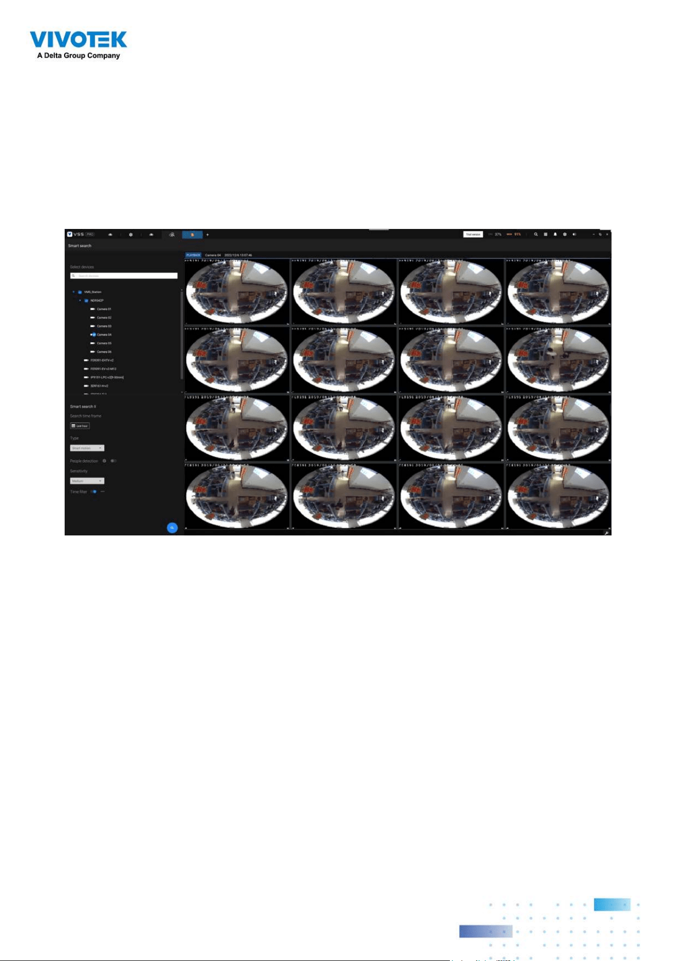
103103
4. The search results display as the snapshots of the associated video clips. Click to
playback the video clips with activities in the detection zones.
Hover the screen with your mouse, and the length of each video clip is displayed.
Note that unless interrupted, the playback continues with all detection zone clips, by
continuing to the successive clips.
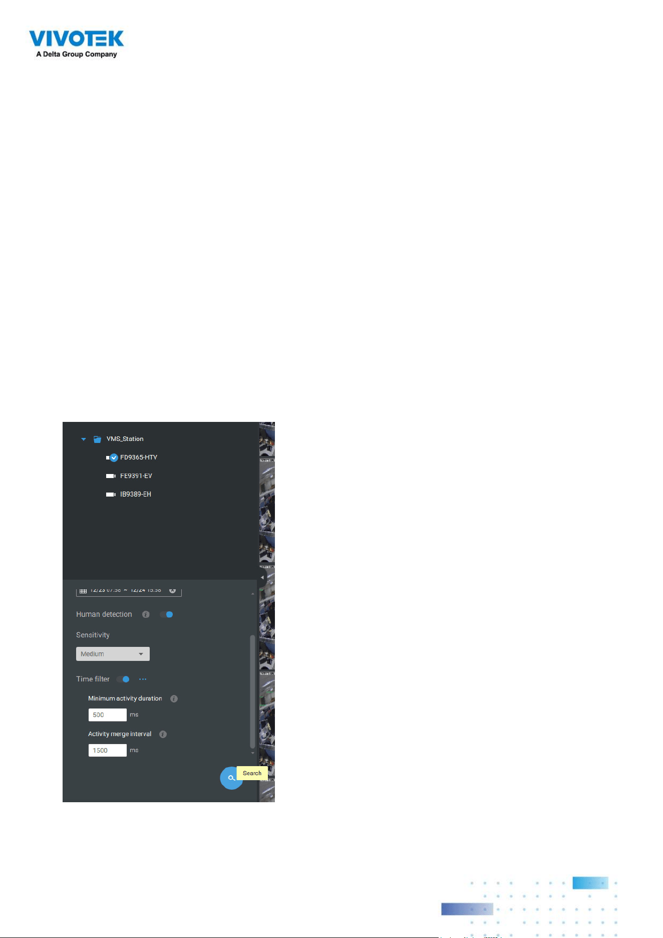
104104
Smart search II is available only for newer line of cameras that come with Smart Motion
detection and other Smart VCA features. Smart search II has the following benefits:
1. Faster search: Metadata is saved with videos coming from the cameras running Smart
VCA detection. With the help of the metadata, the search focuses on the effective
alerted vectors and the adverse effects, e.g., headlights causing dramatic contrast
or small animals passing through, have already been eliminated by the camera. The
search can be more rapidly completed.
2. People detection: The search can be conducted for human activities only. Activities
matching the silhouettes of human will be considered as effective results.
3. Multiple-point polygon: Users can select a region of interest by drawing a easily-
configured polygon. In addition to the pre-configured detection rules on VCA cameras,
users can create their own Smart VCA Detection rules on the VSS search panel
screen.
You can specify the time span, People detection,
Sensitivity level, and time filter parameters in a
Smart Search II panel.
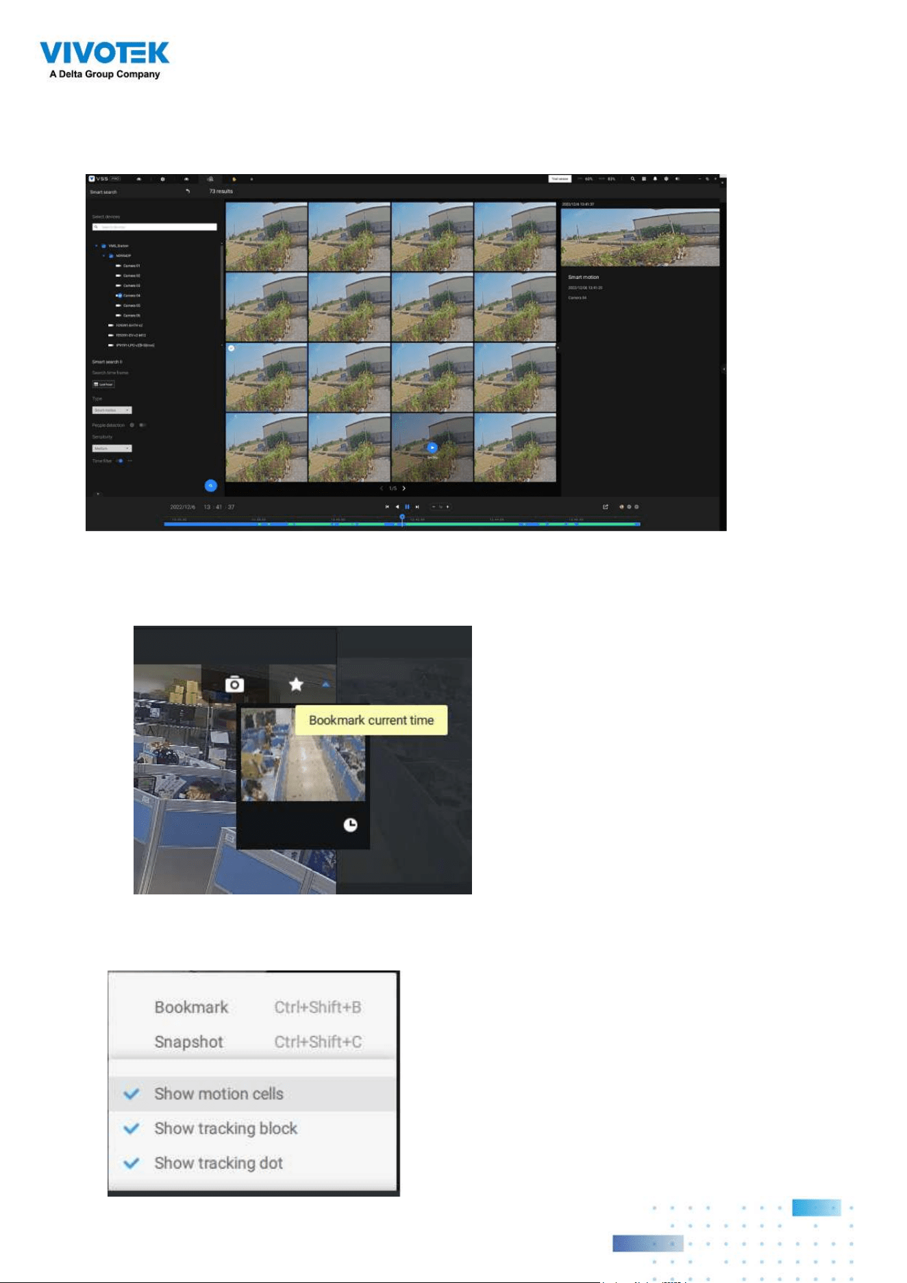
105105
5. You can then click to open any clip of your interest. Each marked event clip will be
indicated by a lighter color on the time line. Select and double-click on a video clip, and
then right-click or select the bookmark or snapshot functions from the upper-right.
Move your cursor to the upper right corner of the playback window to display the
Snapshot and Bookmark buttons. Use them to configure the current play time as a
bookmark or take a snapshot.
While in the full-screen Playback window, you can right-click to select or deselect the
display elements including motion cells, tracking block, and tracking dot.
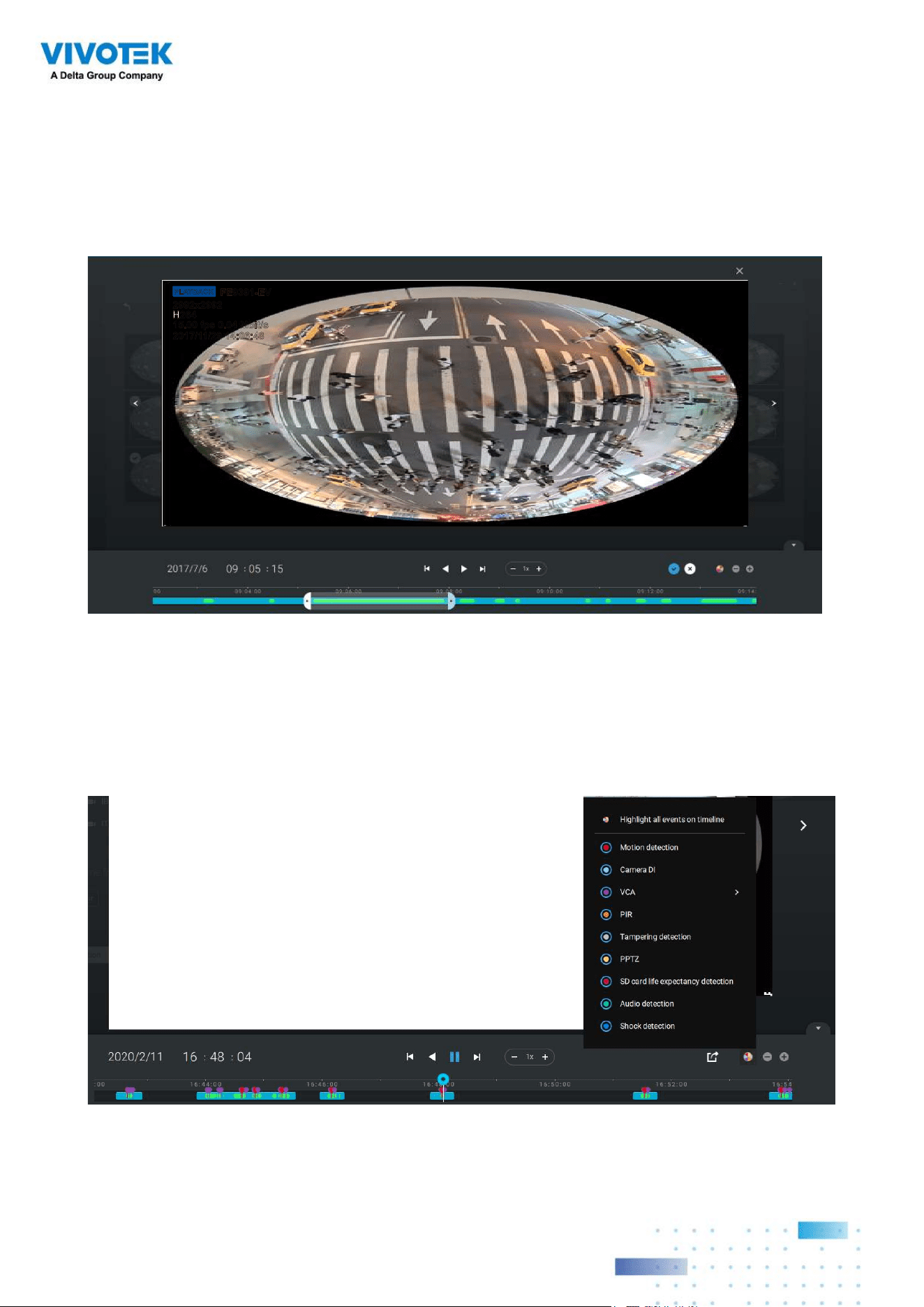
106106
6. If you find important events, use the Export function to mark the start and end points on
the timeline to export a video clip. Use the pull tabs on time line to determine the export
length. By default, the export length is 2 minutes long.
The playback control in the Smart search window is identical to that on the Playback
window.
PLAYBACK
FE9391-EV
2992x2992
H264
15.00 fps 0.04 Mbit/s
2017/11/29 14:06:48
Different events on the timeline are indicated by tags of different colors. Click on the
event highlights button to verify their colors.
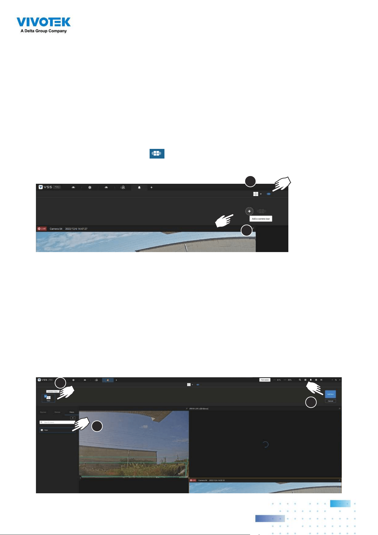
107107
2-17. Tour
A tour can be configured to consecutively display multiple views. A tour allows users to
quickly glimpse through many view cells in a timed pattern. As a tour can contain multiple
views, you should design and configure camera views before configuring a tour.
To configure a tour,
1. Click on the Add a camera tour
button.
2. Click the Add button.
1
2
3. Enter a name for the tour.
4. Single-click to select a view. Select multiple views each by a single click.
5. Click the Add Tour button.
3
4
5
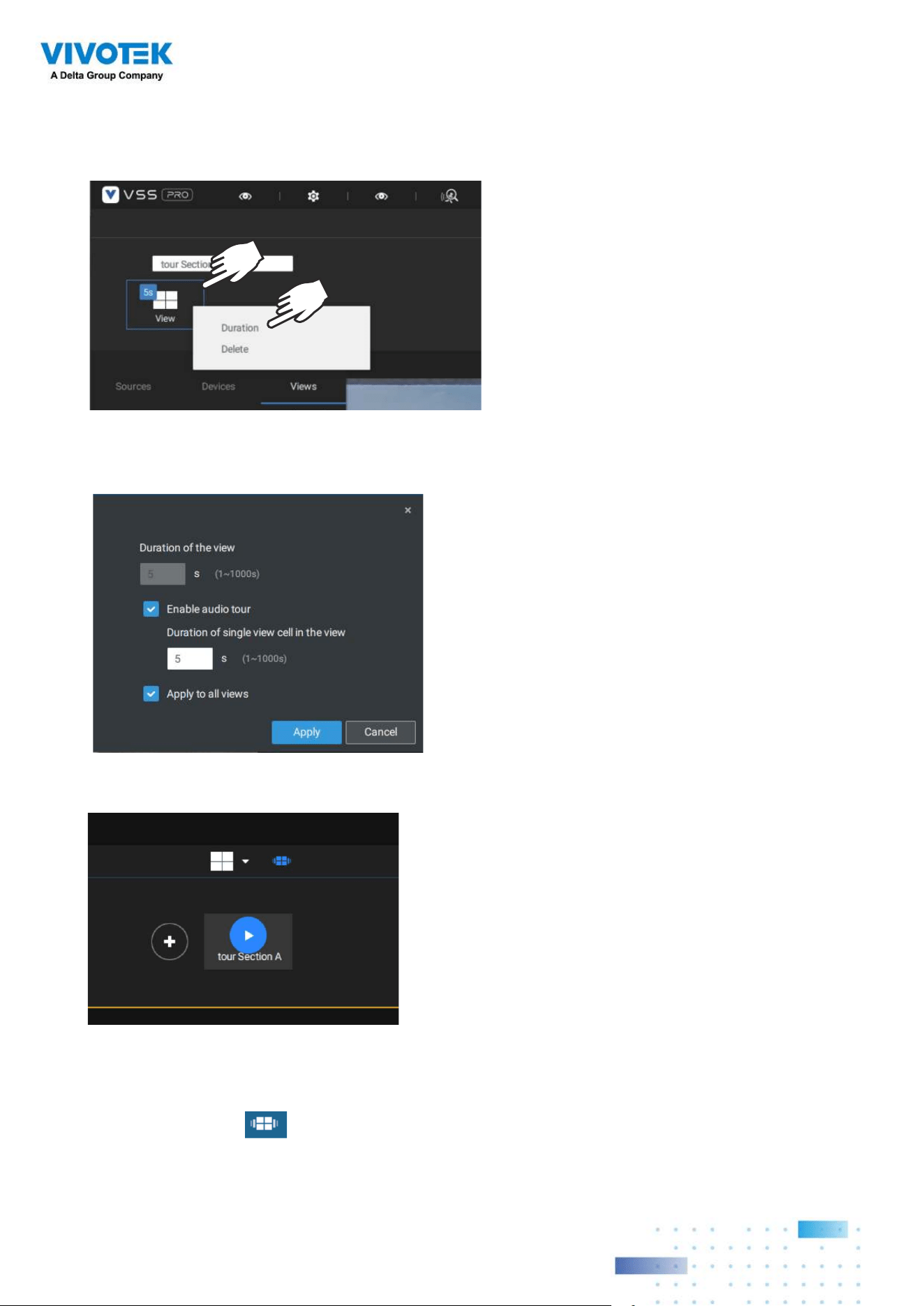
108108
The default for the duration of the display of each view is 5 seconds. You can right-click
on each view to display the Duration of each view. You can apply the same duration of all
views, or allow each view to display on screen for a different span of time.
Mouse over a configured tour, and then click to start a tour.
When playing a tour, and you want to stop the tour, you can left-click or right-click on the
screen.
Click the Tour icon again to return to the singular live view.
You can enable the Audio tour option which plays the audio inputs from each view cell for
a specific period of time.
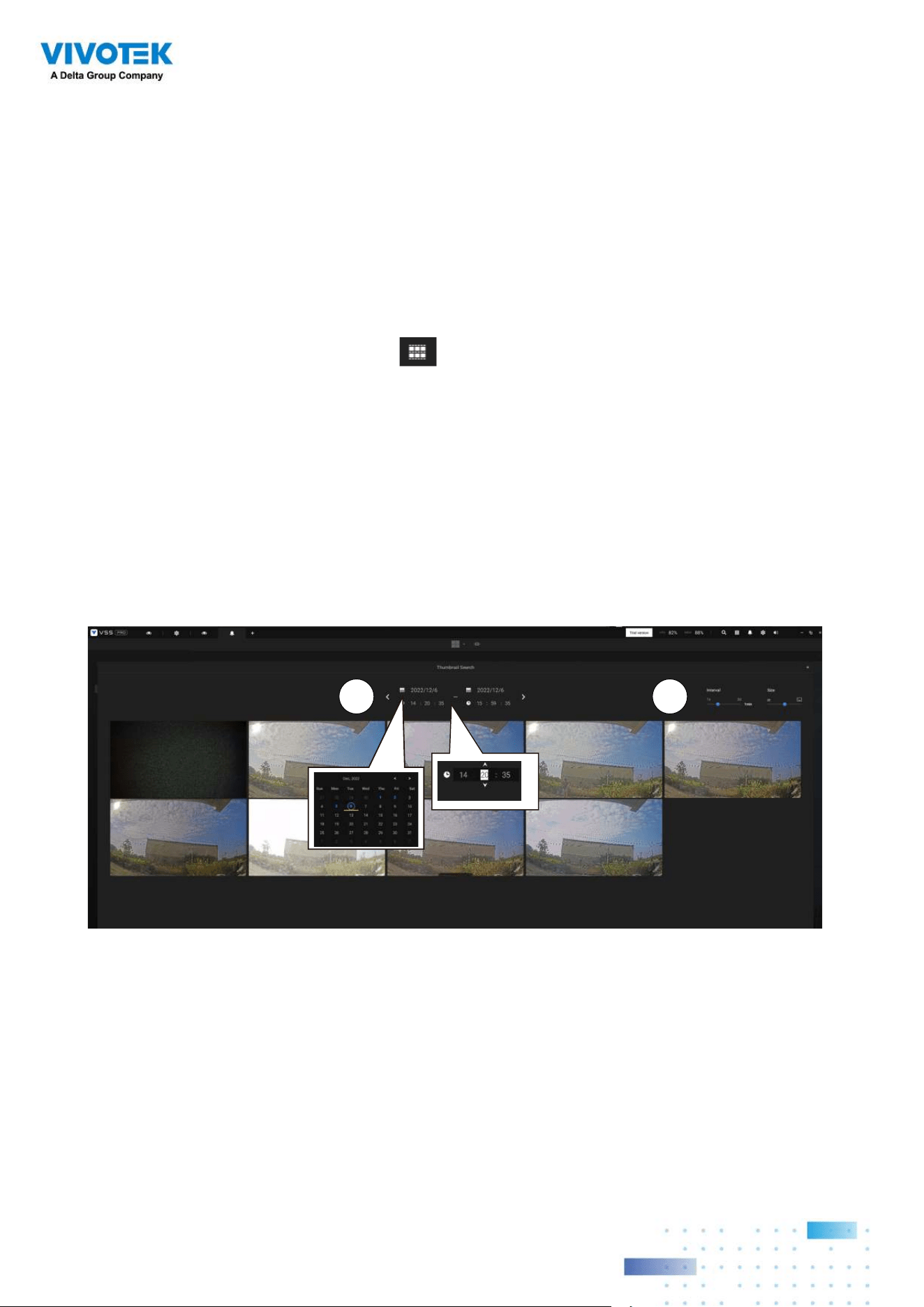
109109
2-18. Thumbnail search
The Thumbnail search function is like doing a post-production editing in film making.
Screens from across different time spans are shown to facilitate the search for evidence.
VSS now supports the search for the instances stored on VIVOTEK's Linux-based NVRs.
Click on the Thumbnail search button to enter the Thumbnail search window.
The default time span is 100 minutes, starting an hour earlier of the current system time.
To use Thumbnail search,
1. Use the date and time selectors to specify a time span during which you suspect the
event of your interest has occurred.
2. If preferred, tune the interval and clip size. The default length for each clip is 10 seconds.
3. If you find a clip might contain an event of your interest, you can click to select, and then
slide left and right to watch the activities within.
21
4. Hover your cursor to the lower center of a clip to display the Play and the More
snapshots options. If you click More snapshots, another window will prompt to display
all frames within the clip.
When you select to display the clip details (specific time span), the time span and the
interval information will change accordingly.
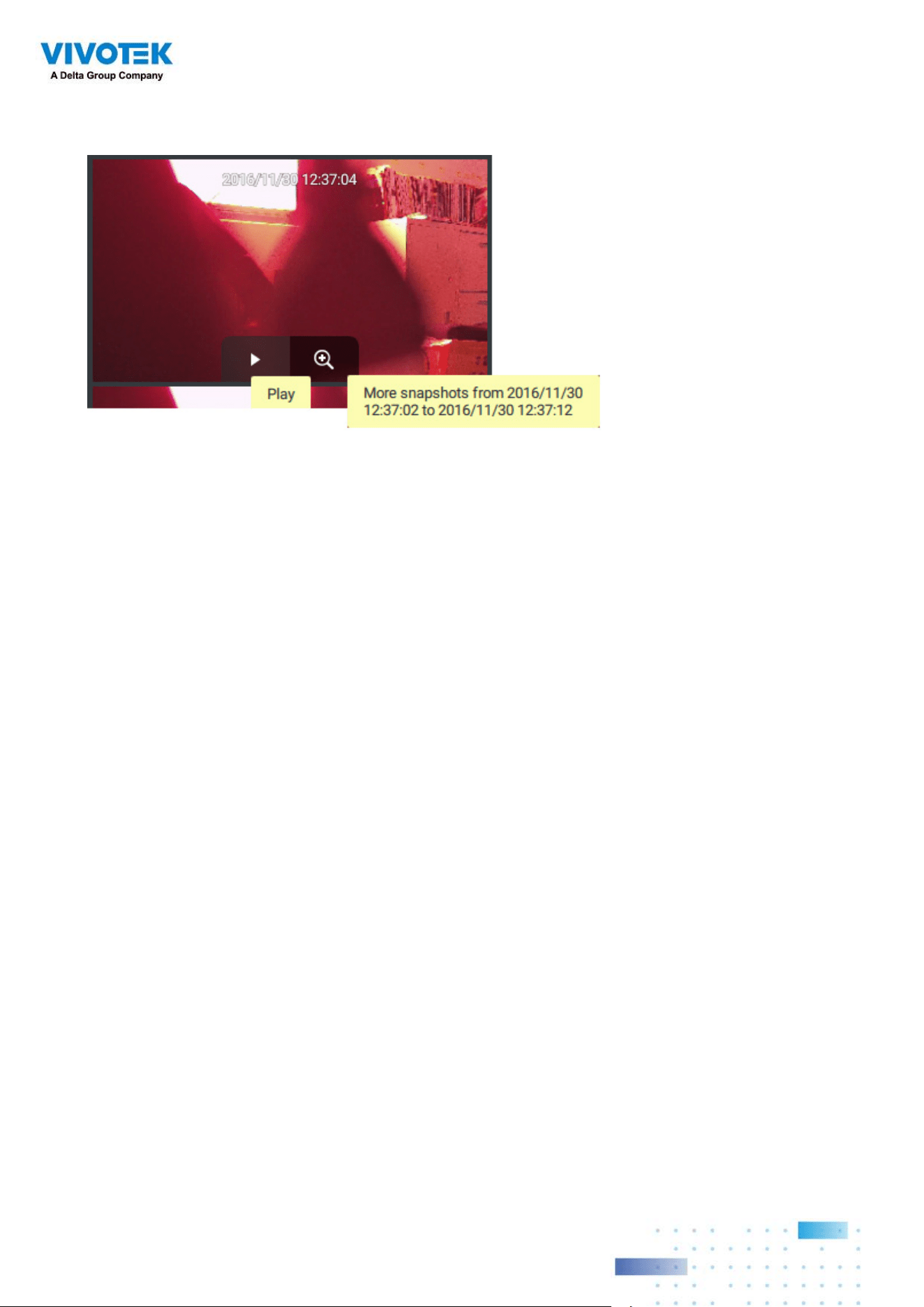
110110
When you find an event of your interest, you can play that video clip and use the export
function on screen to output the evidence. You may also place a bookmark on the timeline.
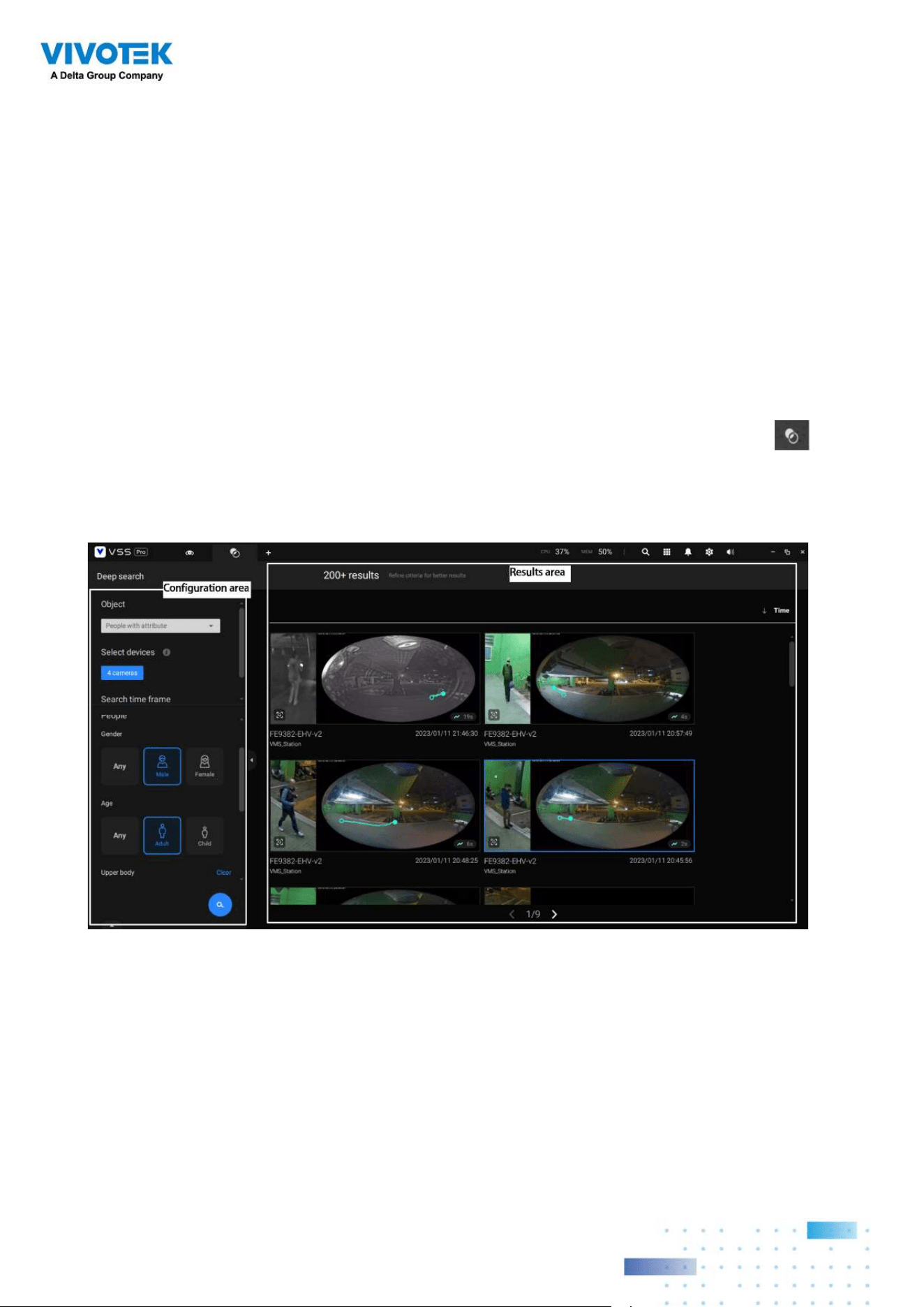
111111
2-19. Deep search
The Deep Search function is an AI-driven post search empowered by VIVOTEK AI cameras.
The Deep Search enhances the capability of post-search with different types of object
metadata, helping users to search the target more precisely and faster using attributes
and behaviors.
To use Deep Search function, please makes sure you added the cameras that support
deep search. There are two ways to access the Deep Search function; one is to click the
search icon and select Deep Search, and the other is to click the associated icon on
a live view cell.
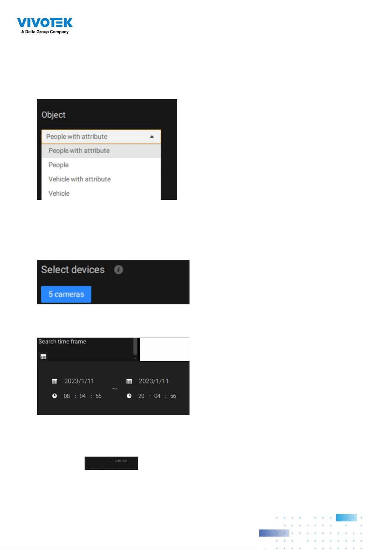
112112
Select the object type in the configuration area, including people, vehicle, people
appearance, and vehicle appearance. Select people or vehicle objects if you want to search
people or vehicles in the recorded video. Select people appearance or vehicle appearance
object if you want to find people or vehicles and know their appearance.
Note that not all cameras support finding all the object types. When users select one type
of object, only the supported cameras will appear in the camera list.
By default, all the cameras that support the object type will be selected. Users can click the
device list and choose the cameras.
Select a time frame using the pull-down menu.
Select the filter by rules or object attributes.
Filter by rule: Search the object appearing or lingering in the virtual area or crossing a
virtual trip-wire. Note that this filter can only be used if you select a single camera. Users
can click the button to select a rule type.
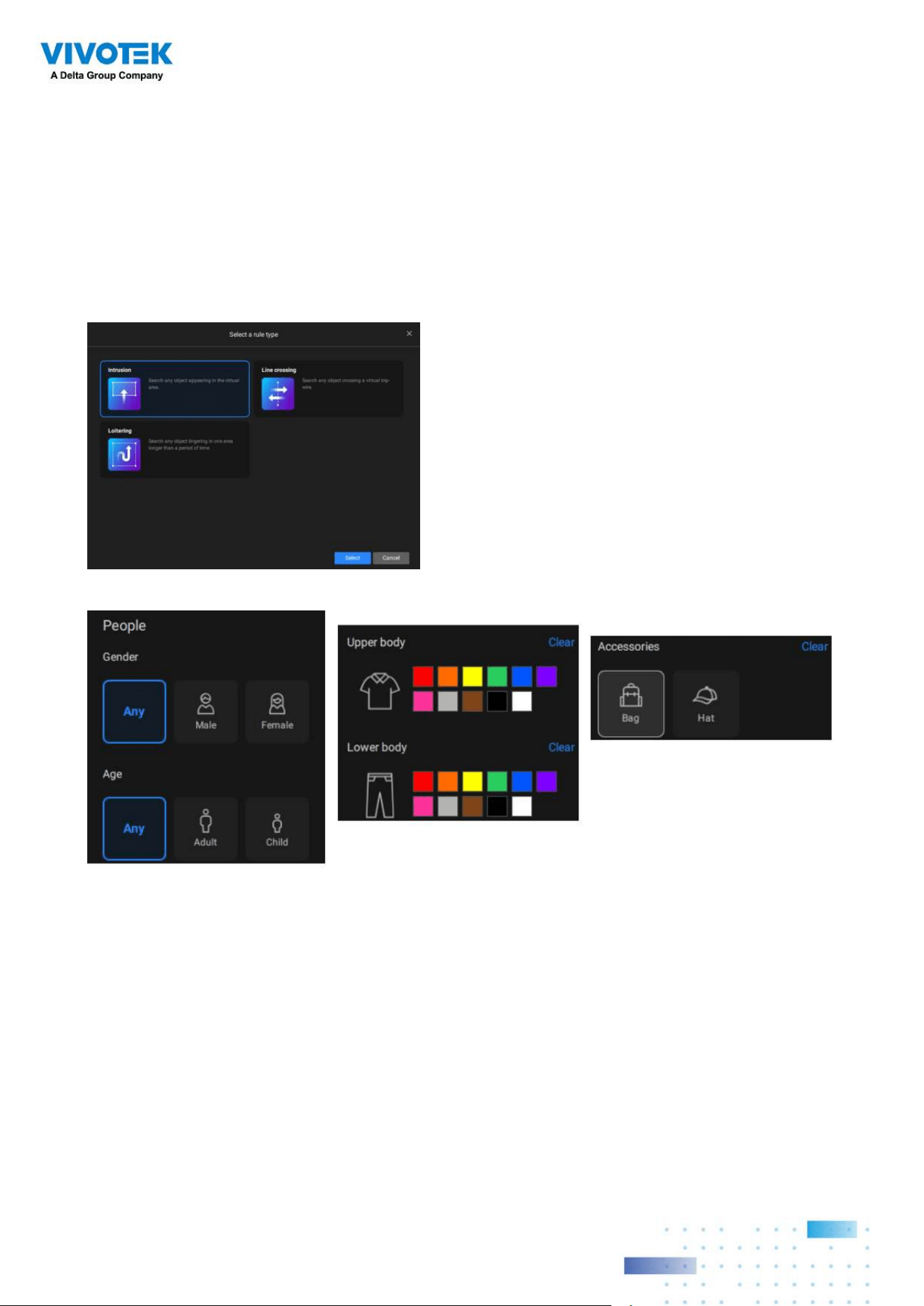
113113
Filter by appearance: filter the object with selected appearance. Note that this filter is
only available when users select the people appearance or vehicle appearance object. The
supported appearance for vehicle and people is listed in the below table.
Object Appearance
People Gender, Age, Clothing color, Accessories
Vehicle Type, Color
Click the search icon, and the results will display in the results area. The number of results
will show at the top of the results area. Each result contains a snapshot of the object and
a video clip of trajectory for the object, and user can click the video clip to playback the
video. Also, users can click Time button to sort the results from latest to oldest or oldest to
latest. If there will be more than 200 search results, only the first 200 results will be listed.
Hence, the first 200 results with the latest time will be listed if the time is sorted from the
latest to the oldest. The first 200 results with the oldest time will be listed if the time is
sorted from the oldest to latest.
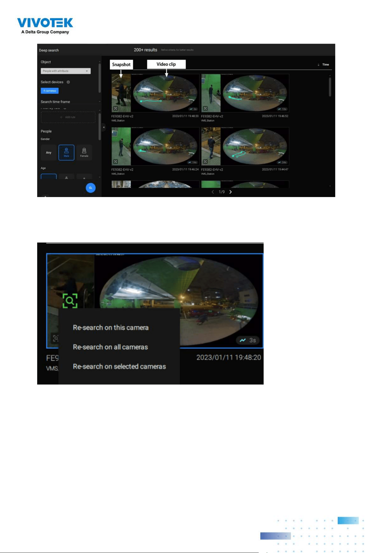
114114
Re-search: After all the search results shown by above three filters, users can click the
snapshot of the object to search for similar objects. Users can select to apply Re-search
on current camera, all cameras, or the selected cameras.
IMPORTANT:
1. If two colors are selected in the clothing or vehicle color option, the object containing
both colors will be listed in the search result.
2.
If Re-search takes more than 90 seconds to search, it will timeout, and no results will be
shown. Please shorten your search time frame or reduce the selected camera numbers
to narrow the search range to avoid this situation. CPU performance will inuence the
search speed.
3.
Please refers to VIVOTEK’S website and check the supported cameras for Deep
Search. (https://blob.vivotek.com/downloadle/SmartVca/camera-analytic-chart_en.pdf)
4. With a newly added camera, the Deep search takes 3 to 5 minutes to acquire serach
data. The searched results and objects will be acquired after antoher 2 to 3 minutes.
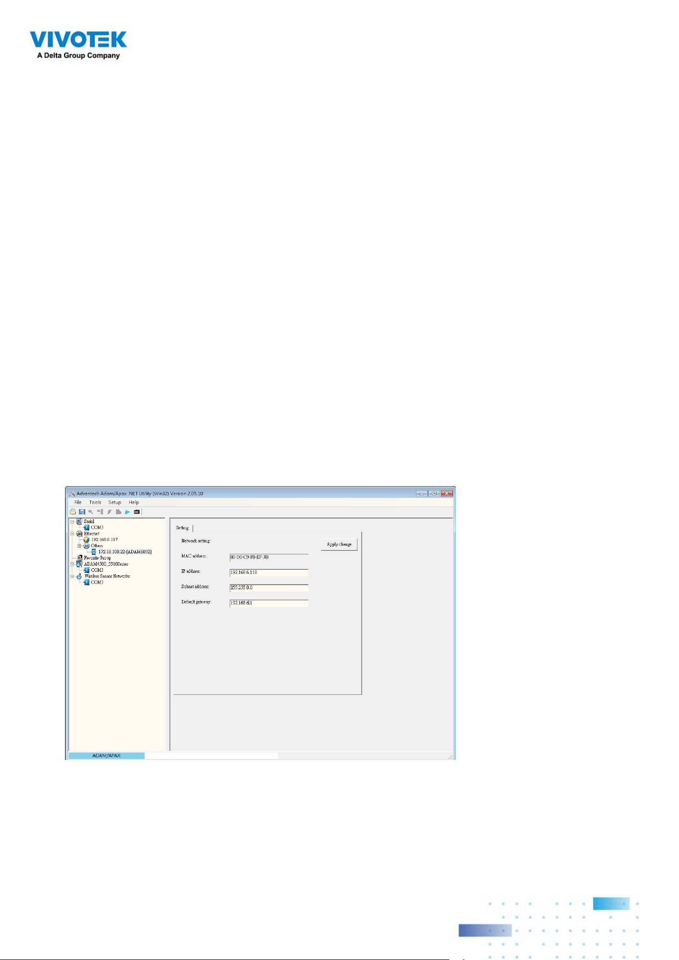
115115
Chapter 3 Applications:
3-1. I/O DI/DO Devices
IO Box and Related
Configuration
Use the software utility that comes with the IO box, e.g., Advantech's Adam/Apax.NET
utility, to configure IP address, and test the DI/DO connectivity. The connections to external
devices should be completed before configuration on the software.
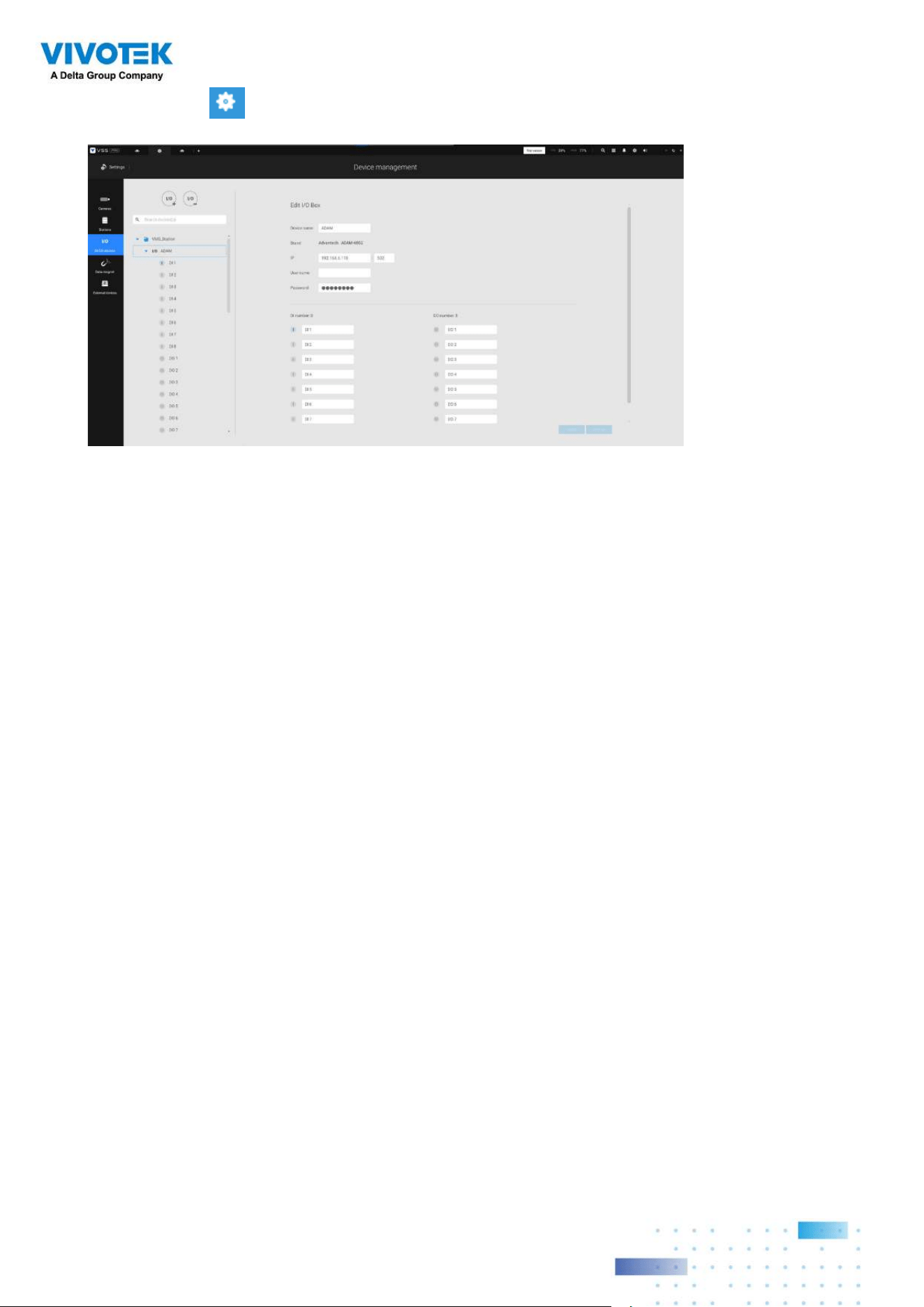
116116
Enter the I/O box's IP addess and credentials, and select the correct model name from the
pull-down list on the right. Click the Apply button to proceed. The current I/O connections
are also displayed on screen, such that the status is displayed when DI pins are connected
to detection devices.
Enter Settings > Device > DI/DO Device. Click the add I/O button on top.
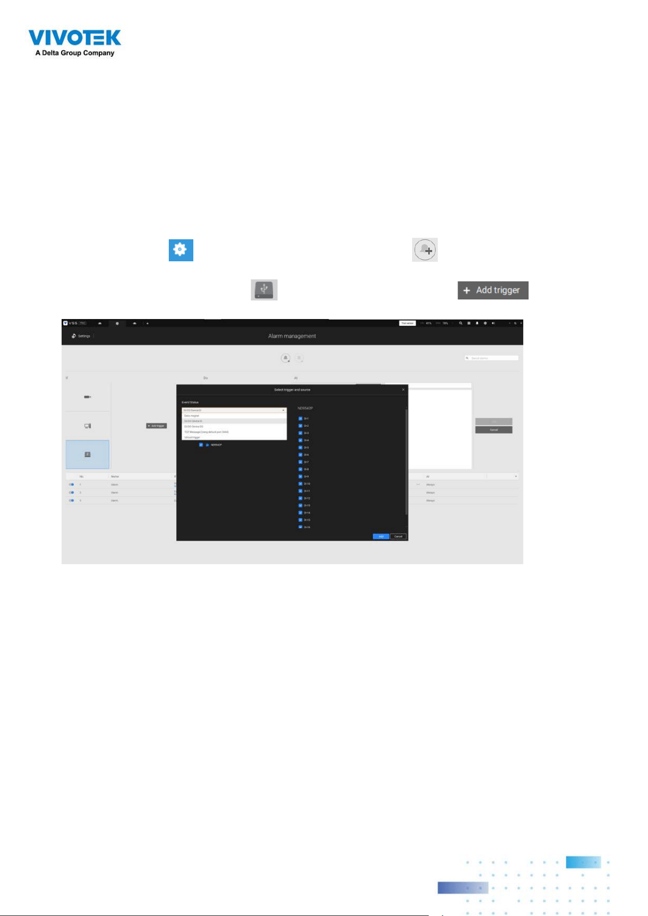
117117
The Select trigger and source window will prompt.
Select either the I/O Box DI or DO as the triggering source.
Configuring I/O Box DI/
DO as a Trigger or Action
in Alarm
Enter the Settings > Alarm window. Click the Add alarm button on top.
Select the External Device event , and then click the Add trigger button.
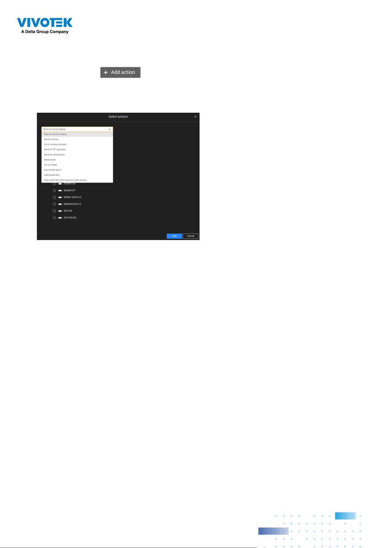
118118
Select one or multiple DIs as the triggering source and click the Apply button.
Click Add action , and select a corresponding action, such as sending live
streaming, record videos, trigger a DO, sending an HTTP request, or sending an Email.
When done, click the Add button.
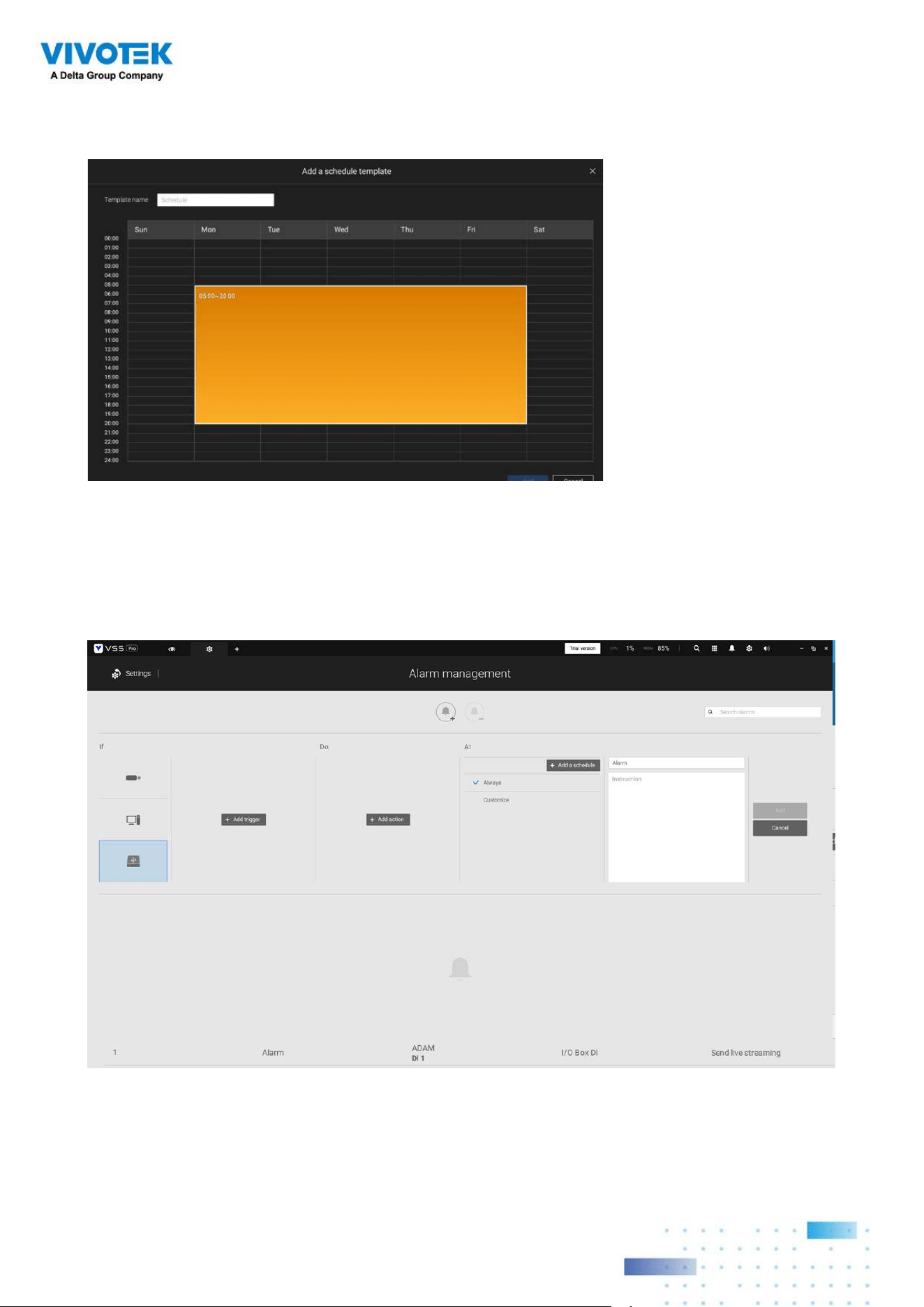
119119
Enter a name for your Alarm, and add description for your configuration, e.g., "intrusion
detected on the front door." When done, click the Add button. The Alarm configuration
takes effect immediately.
Configure a schedule during which the Alarm configuration will take effect. If no special
time span is needed, you can simply select Always.

120120
NOTE:
If an I/O module is started later than the VSS server, you may not be able to access the I/O
module. You should then re-start the VSS service.
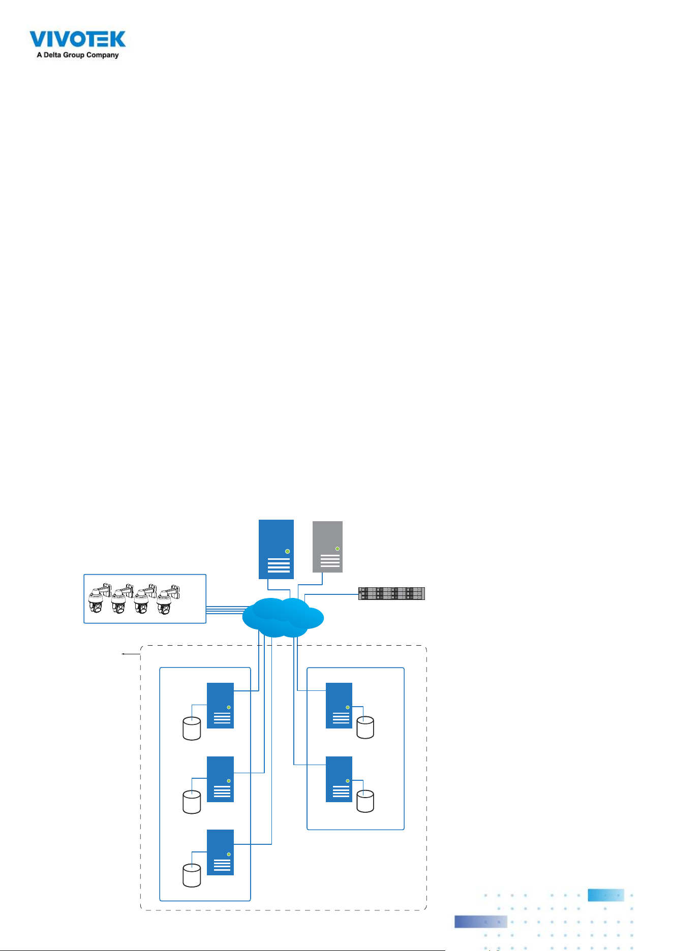
121121
3-2. Configuring Redundant
Servers - Failover
VSS servers can be congured into two groups: Active and Redundant. The Active group
performs daily recording and monitoring tasks, while the Redundant group acts as the
standby servers. In the event of server failures, the Redundant group becomes active, and
takes over the recording task.
The Redundant server group conguration consists of the following:
1. One VSS server designated as the CMS (Central Management server) VSS central
management server. Another VSS server can serve as a CMS failover server.
2. At least one VSS server in the Active group.
3. At least one VSS server in the Redundant group.
4. Gb/s network or higher-speed connections among the servers. All Active and Redundant
groups can reside in different subnets, provided that static IPs are congured for these
servers.
Active VSS servers Redundant VSS servers
CMS VSS
Active Group Redundant Group
Node 1
Node 2
Node 1
Node 2
Node 3
External storage /
NAS
Network Cameras
. . . . .
Server Group
CMS Failover
LAN
IMPORTANT:
For a Redundant server conguration, you must rst enlist VSS servers in the Stations
conguration page before conguring the Redundant server groups. See the Stations
conguration page.
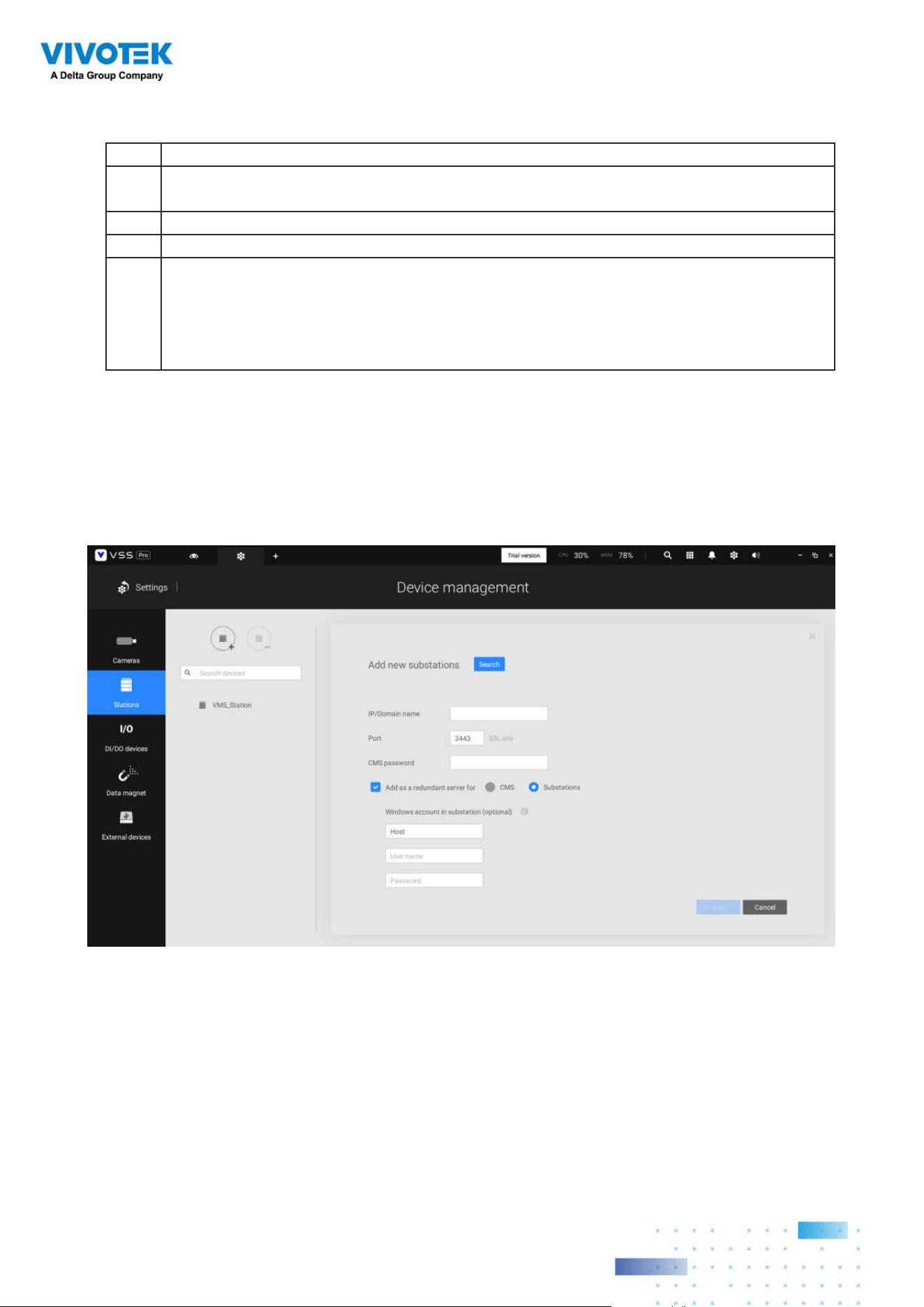
122122
Below are the denitions of server roles:
1. CMS VSS server: The main access portal for the conguration.
1-1. CMS server is where the Failover conguration takes place.
1-2. CMS continuously polls to check the hearbeats to monitor the statuses of all
Active and Redundant servers.
1-3. CMS regularly backs up the congurations on Active servers.
1-4. CMS assigns redundant server(s) to the takeover of a failed Active server.
1-5. In a Redundant server conguration, the CMS is supposed to be up and running
at all time. If the CMS server fails, the server failover and failback operation will
not take place. It is therefore preferrable to congure a CMS redundant server,
and install the CMS server at a high up-time environment, such as on a VMWare
conguration.
3. Active servers: Active VSS servers are the work horses that perform recording and
monitoring tasks.
4.
Redundant servers: The Redundant servers are actually active-standbys. They
participate to continue video recording in the event of active server failures. It is
recommended for the Redundant servers to have an equivalent or higher processing
power than the Active servers. The same applies to the size of storage volumes and the
disk drives' write performance.
Note that you cannot congure a Redundant server by opening a local console.
2.
CMS Redundant server: This is a failover server that serves as the backup for the CMS
server.
Note that this redundant server is congured in
Settings > Devices > Stations. Click
Add Stations, and select "
Add as a redundant server for" "CMS." See next section
for the conguration procedure.
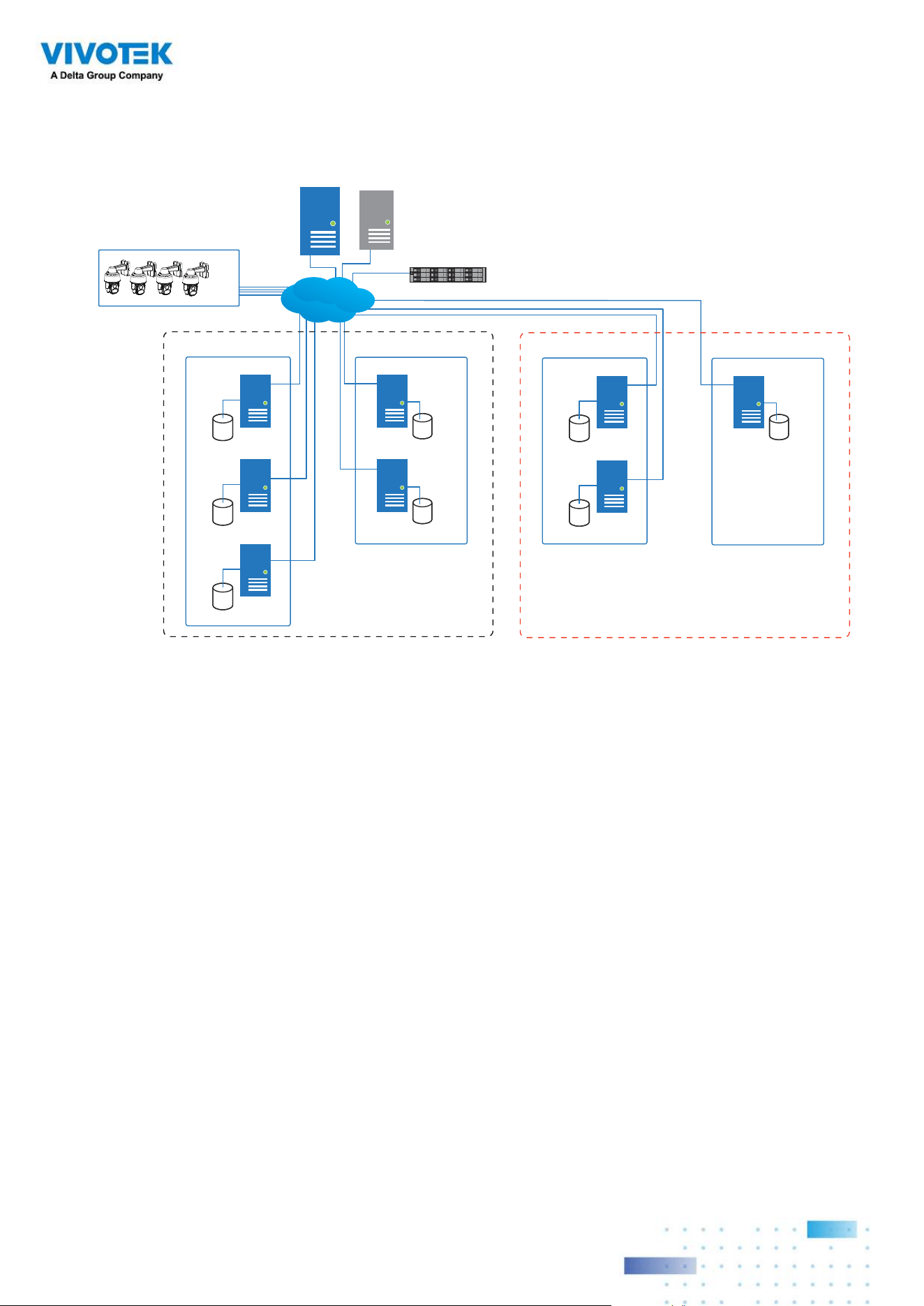
123123
Multiple Active and Redundant groups can be created.
Active VSS servers Redundant VSS servers
CMS VSS
Active Group Redundant Group
Node 1
Node 2
Node 1
Node 2
Node 3
External storage /
NAS
Network Cameras
. . . . .
Server Group 1
Active VSS servers Redundant VSS servers
Active Group Redundant Group
Node 1
Node 1
Node 2
Server Group 2
CMS Failover
LAN
Each Redundant server can serve as the backup for ONE Active server. Depending
on the number of the Active and Redundant servers, if the number of failed servers
exceeds the number of Redundant servers, the failover will be abandoned. For example,
if 2 Active servers failed, and there is only 1 Redundant server available, the second
Active server that failed will be abandoned.
The conditions during the failover process are illustrated below:
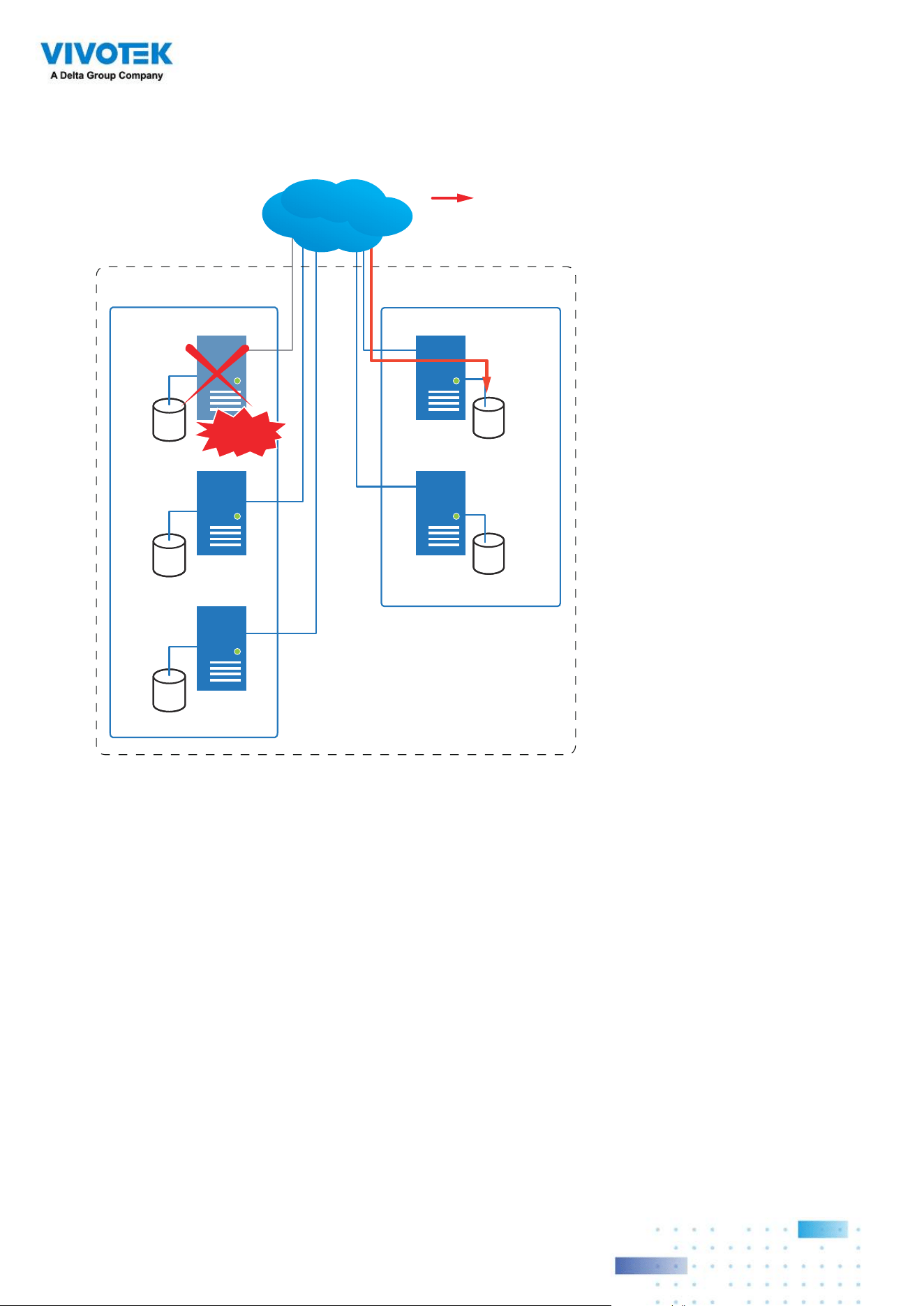
124124
In the event of a server failover, a VSS server in the Redundant group takes over the
recording task. Note that depending on the network environment, the takeover can take up
to 5 minutes.
Active VSS servers Redundant VSS servers
Active Group Redundant Group
Node 1
Node 2
Node 1
Node 2
Node 3
Server Group
Recording
LAN
Failed!
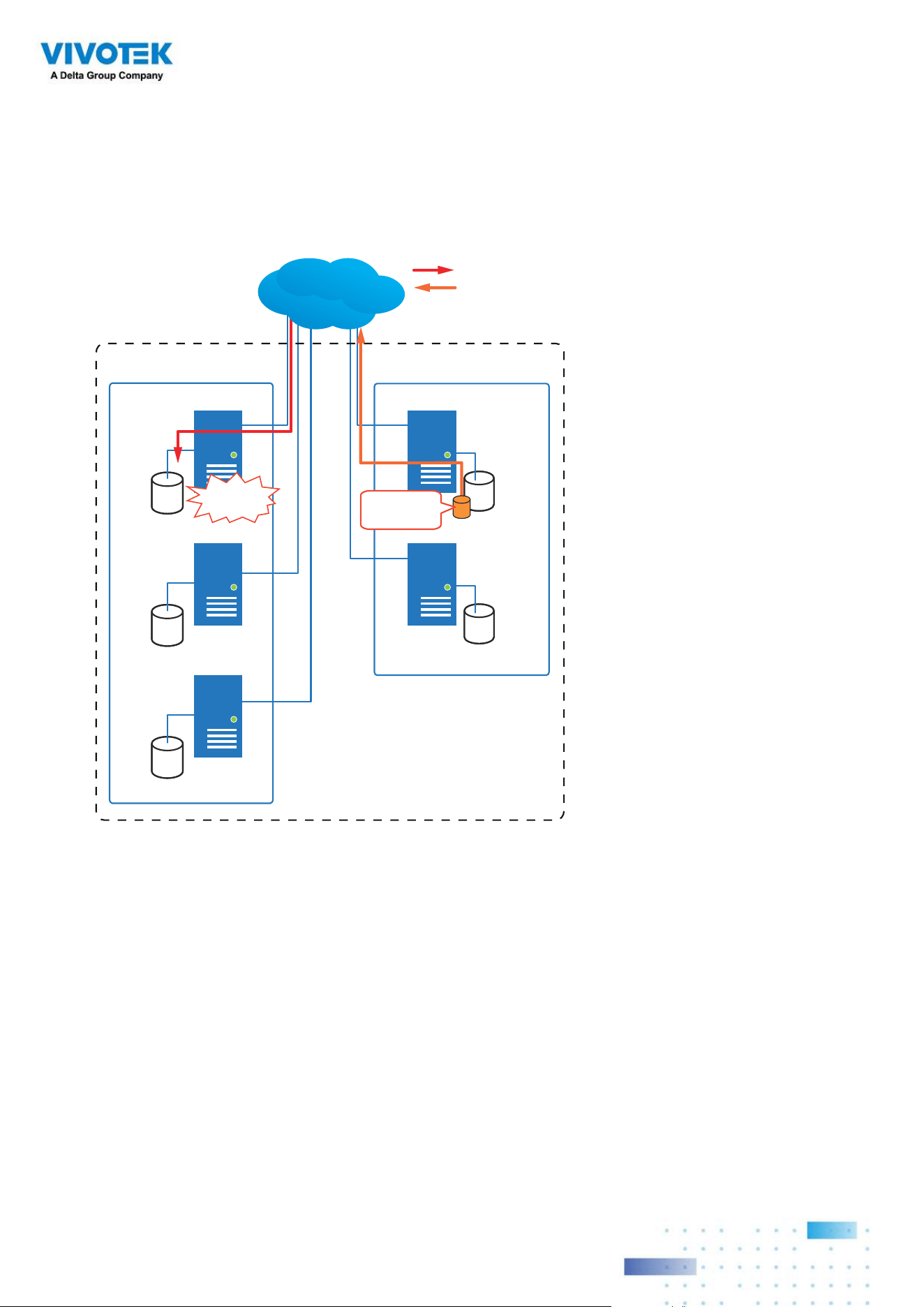
125125
Once the server in the Active group is restored to normal operation, and a CMS server
requests for the recordings and data occurred during the time the active server failed,
the requests will be fulfilled by a shared volume on the redundant server. Due to the
concerns with network bandwidth and processing power, the restored active server does
not synchronize its recording pool with that on the redundant server after the failover and
failback process.
Active VSS servers Redundant VSS servers
Active Group Redundant Group
Node 1
Node 2
Node 1
Node 2
Node 3
Server Group
Recovered!
Shared
Volume
LAN
Recording
Playback & Search
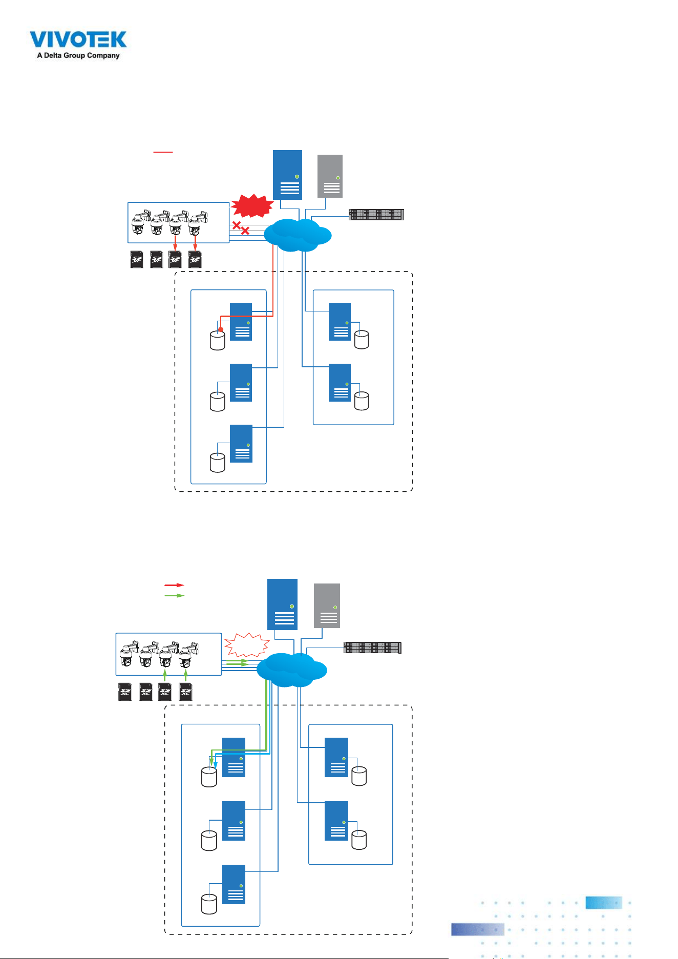
126126
In terms of network failure, the VSS configuration supports Seamless Recording. For
cameras equipped with an SD card, video is recorded to the SD cards in the event of
network failure. Of course, the cameras must have a backup power source, such as a DC
12V input. In cases such as the only PoE switch or PoE mid-span fails, power is lost.
Active VSS servers Redundant VSS servers
CMS VSS
Active Group Redundant Group
Node 1
Node 2
Node 1
Node 2
Node 3
External storage /
NAS
Network Cameras
. . . . .
Server Group 1
Network
Failure
Recording
CMS Failover
LAN
Once the network connection is restored, the VSS servers resume the recording task and
also retrieve video segments from the SD cards. The video segments recorded during
the network failure will be stitched up with those occurred before and after the network
failure. The retrieval speed varies depending on the available network bandwidth and CPU
resources.
Active VSS servers Redundant VSS servers
CMS VSS
Active Group Redundant Group
Node 1
Node 2
Node 1
Node 2
Node 3
External storage /
NAS
Network Cameras
. . . . .
Server Group 1
Recording
Retrieval
LAN
Recovered!
CMS Failover
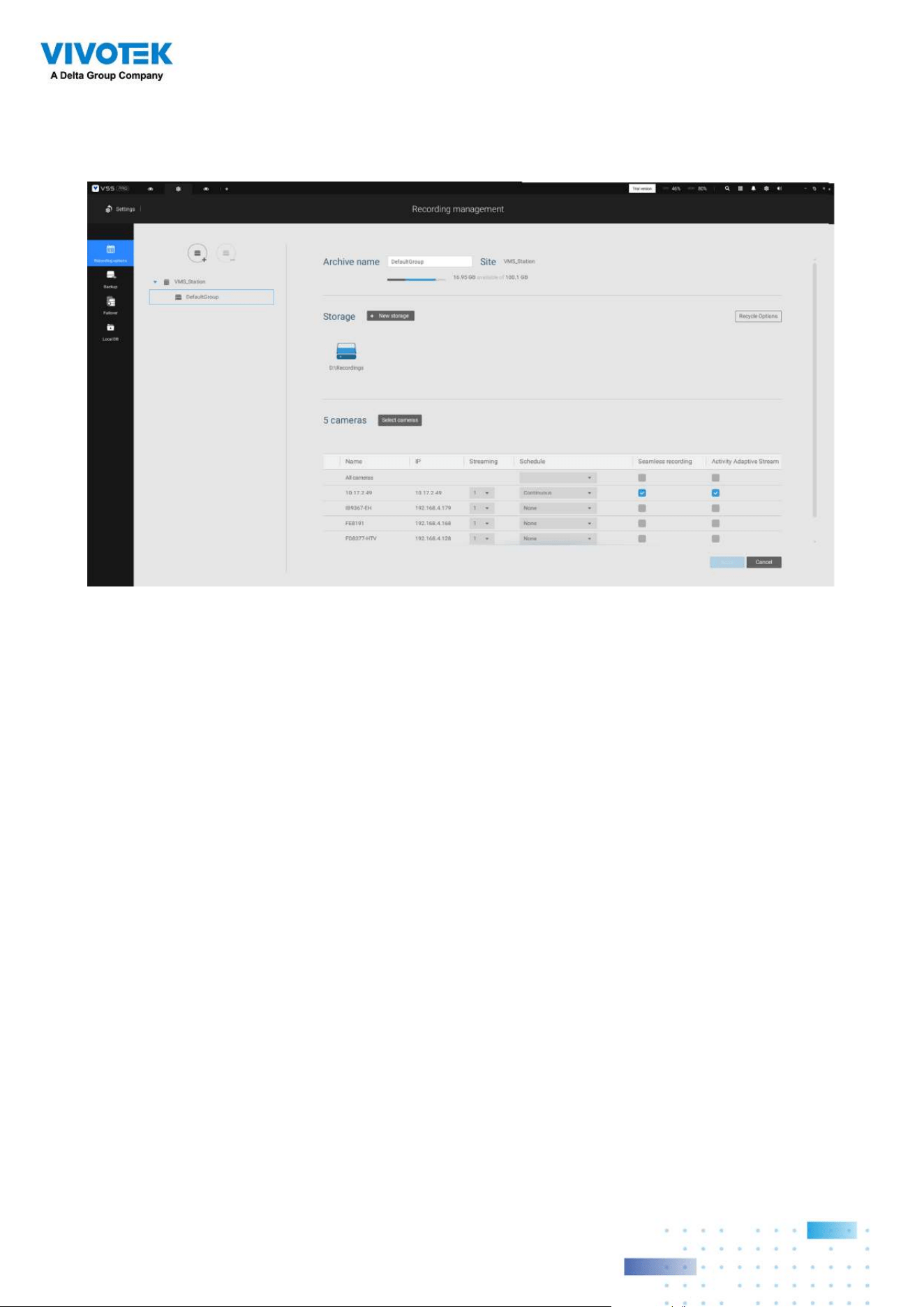
127127
To enable Seamless recording, find the associated option in
Settings
>
Recording
options
, and select the Seamless recording checkboxes. Camera models that support the
Seamless recording option will have it listed.
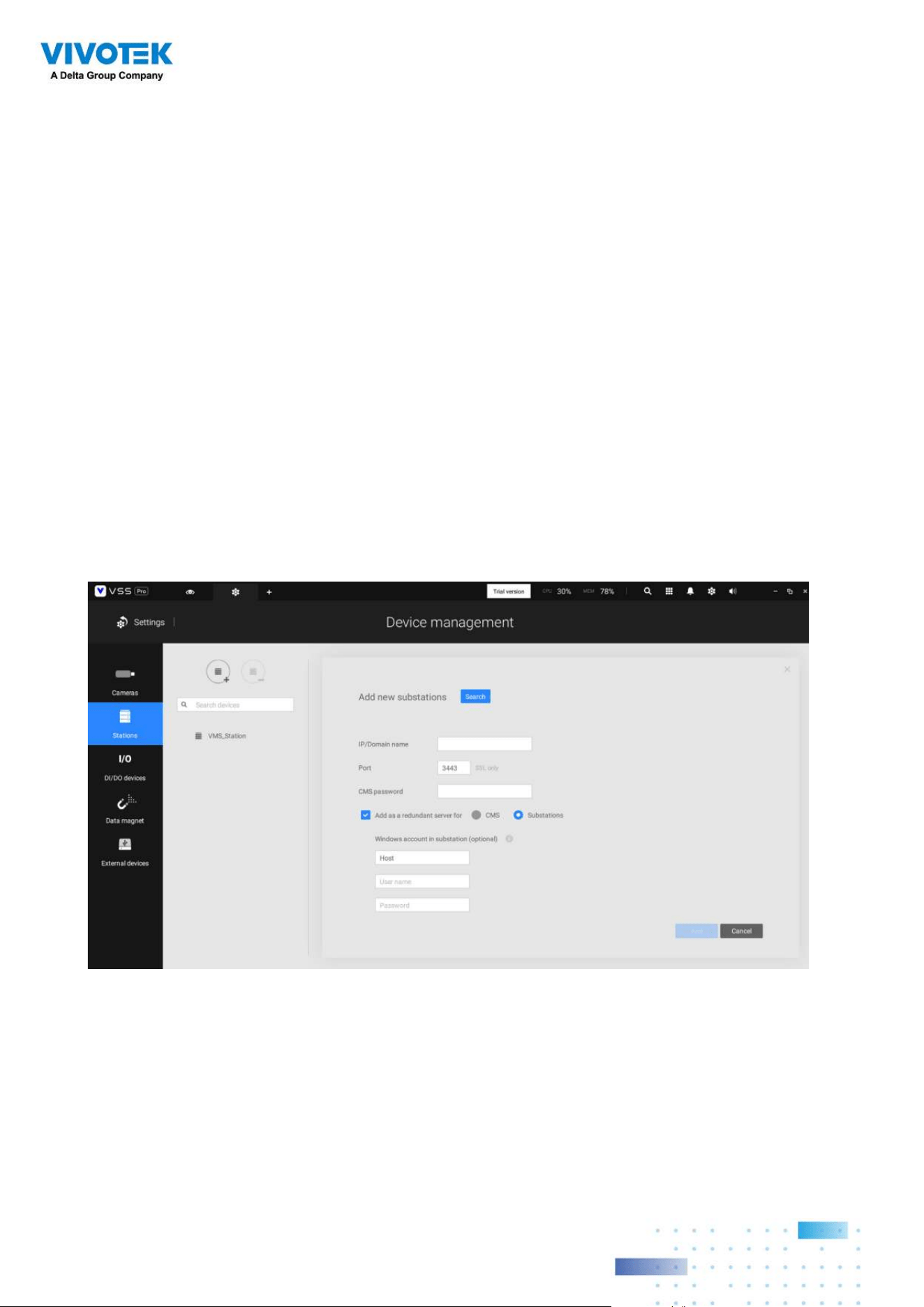
128128
• If you are adding a Redundant server, select the "Add as a redundant server"
checkbox, for either a CMS server or VSS Substations.
• If you are adding a server without selecting this checkbox, it will be considered as an
Active server.
• When adding a Redundant server, you can provide a Windows account 802.1x domain
user name and password. A Redundant server requires this because a full access to
the recorded data is required during the failover and failback process.
Failover Configuration
Process
Before Failover conguration, you need to add other servers to your Failover conguration.
Below is a screen from the Stations management window.
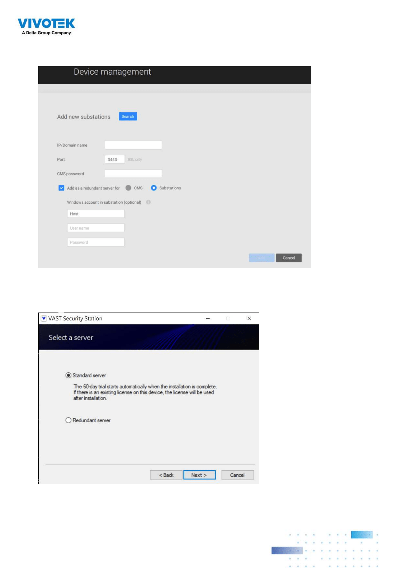
129129
When the "
Add as a redundant server
" checkbox is selected, enter the name of your
Windows domain and the user credentials for a full access to the Redundant server.
Note that it is a must for the Redundant server to be installed differently by selecting a
"
Redundant server
" checkbox during the installation process.
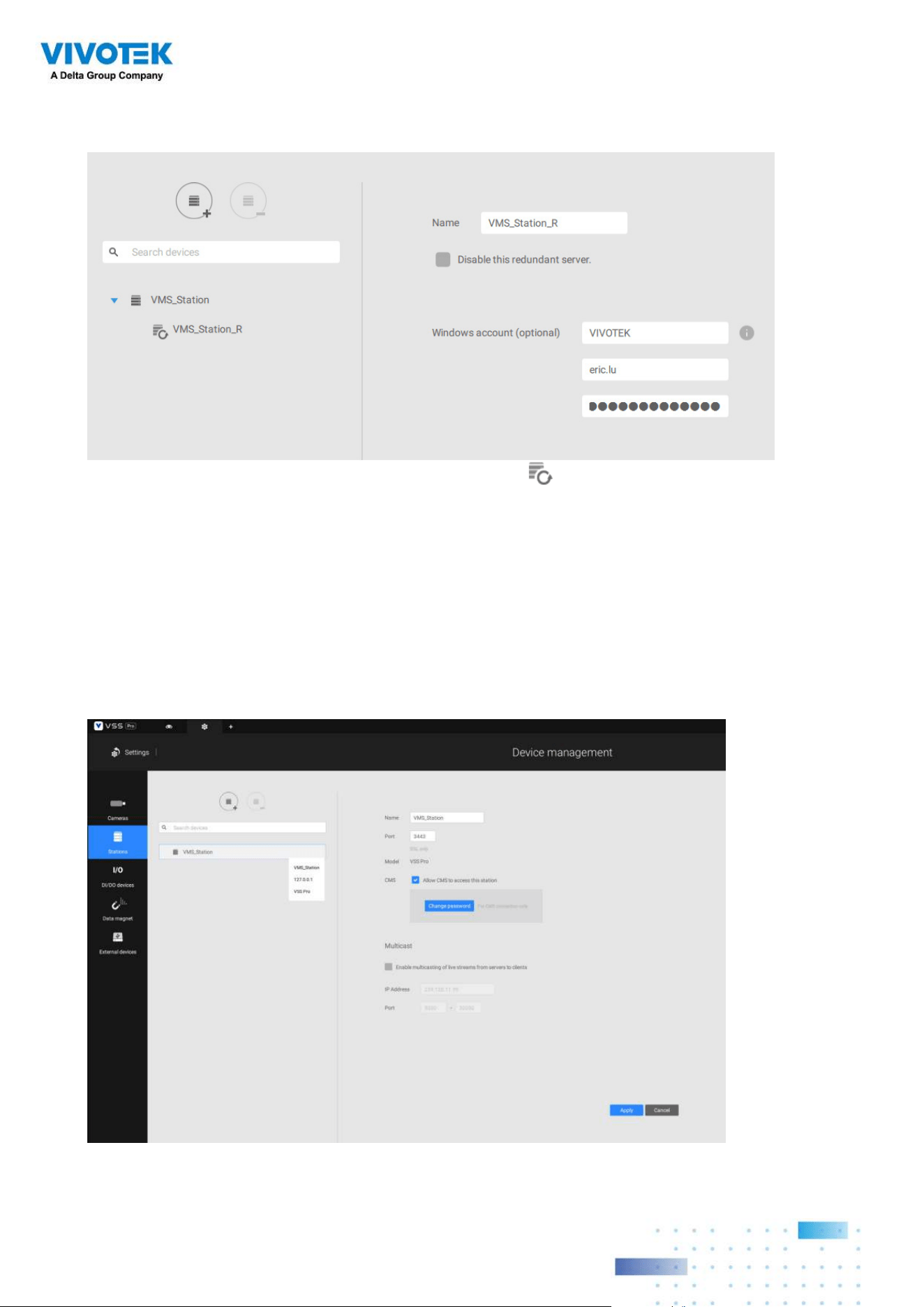
130130
Note that on the
Active servers
, you should congure them as the subordinates to your
CMS VSS server. On a web console to these servers, open the Station management page,
and select "
Allow CMS to access this station
." Create a common password for the CMS
hierarchy.
When a Redundant server is successfully added, the server will be listed under your VMS
station.
A Redundant server comes with an associated icon, .
An Active server must have a CMS password congured for the hierarchical conguration.
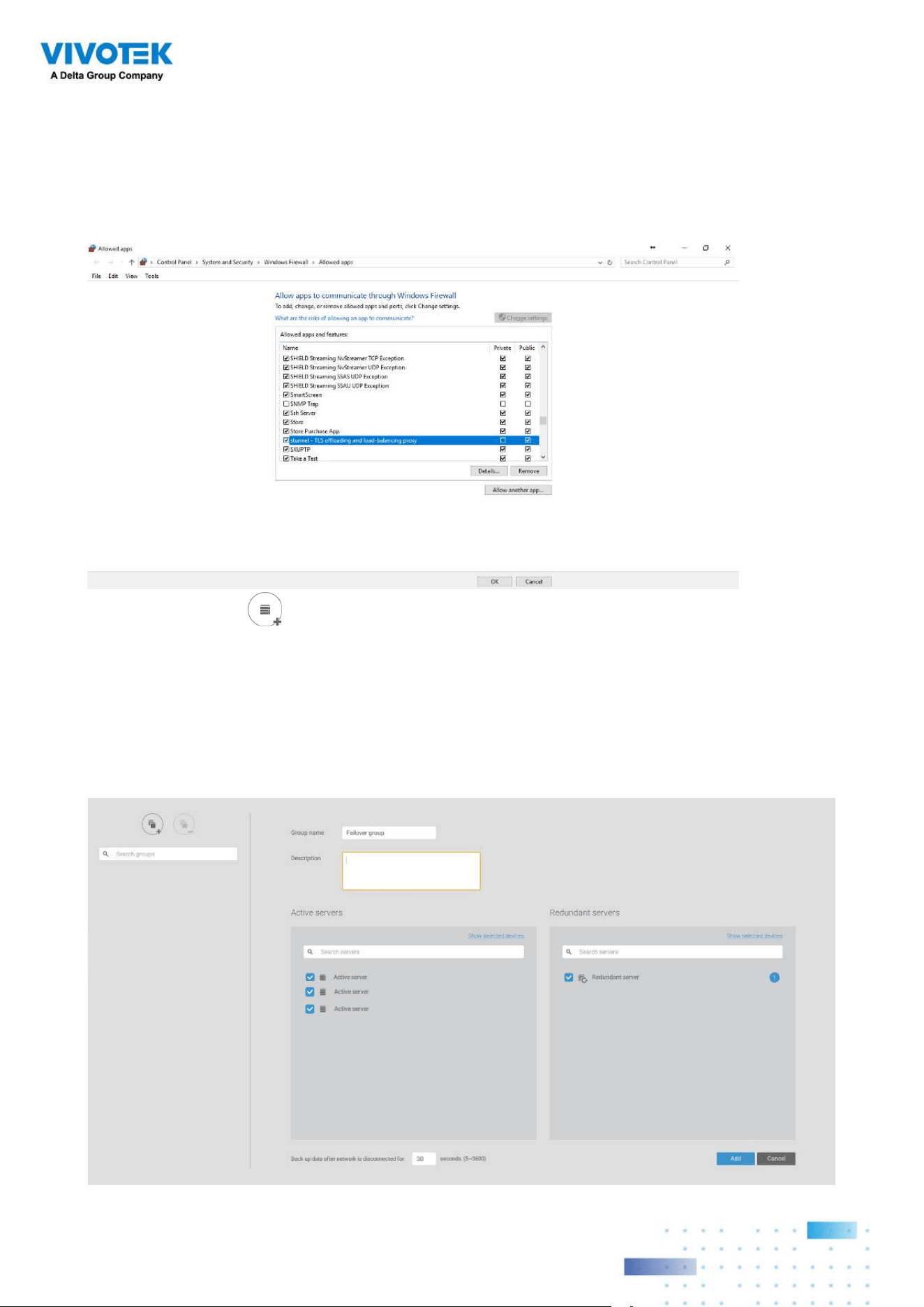
131131
Two agents will be running on the Active and Redundant servers, "stunnel" and
"VMSWebServer." Make sure they are not blocked out by your firewall. These agents can be
found in the default folders below:
C:\Program Files (x86)\VIVOTEK Inc\sTunnel\stunnel.exe
C:\Program Files (x86)\VIVOTEK Inc\VAST\Server\VMSWebServer.exe
Click on the Add button to create a Redundant server group. The Active and
Redundant servers you enlisted on the Stations page should all be listed below. Select the
members of the Redundant group, and click Add to complete.
The default for the network disconnection timeout is 30 seconds. It is not recommended to
congure a very short timeout, e.g., 5 seconds, because if doing so, a temporary network
disorder can make servers consider the Active server(s) have failed.
1
2
3
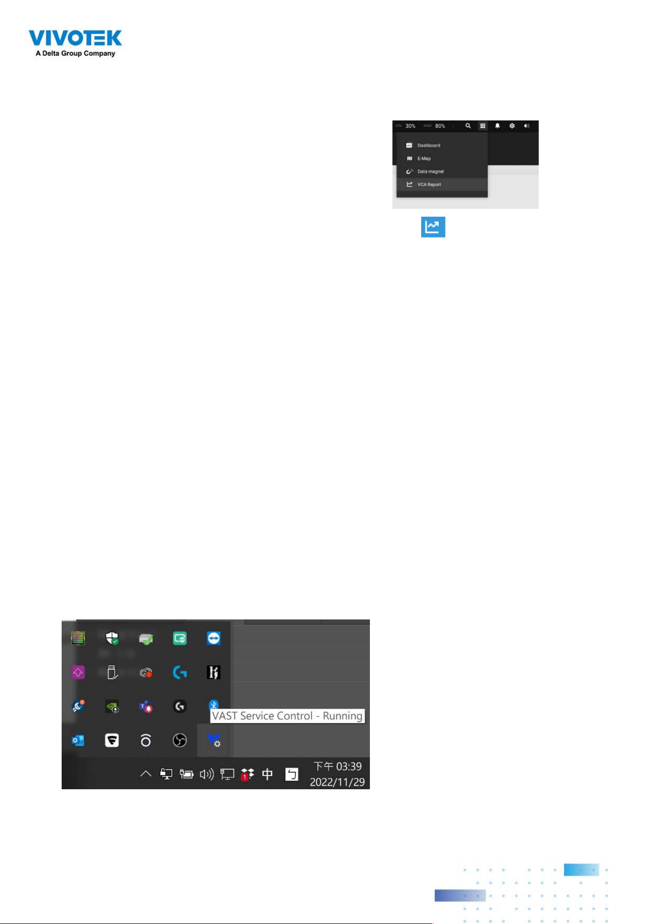
132132
3-3. VCA (Video Content
Analysis)
The VCA Report utility is started from the tool bar on top, . The VCA Report utility
provides comprehensive graphs and line charts for quick access to the data collected
through VIVOTEK's People Counting modules, such as the SC8131 stereo camera.
Statistical results is refreshed by hour or minutes, and you can compare the results
acquired through different time periods or among different surveillance areas. These
data help figuring the customer flow in retails so that shop owners can optimize the
arrangement of store layout, or mange queues more efficiently.
Note that the conguration of detection methods in People Counting still occur on a web
console to individual cameras. It is not congurable through the VSS LiveClient.
Prerequisites:
The prerequisites for using the VCA Report are:
1. The monitoring server running the VCA Report utility must be up and running during
the time the counting VCA is taking place. If you power off the server, the counting
metadata generated during the server down time will not be available for analysis.
The VSS server instance runs in the background. The VSS management console needs
not be started during the VCA Report data collection process.
2. Cameras running the VCA utilities have been configured and added into the VSS
deployment. The instances of available VCA rules will be listed in the Area panel.
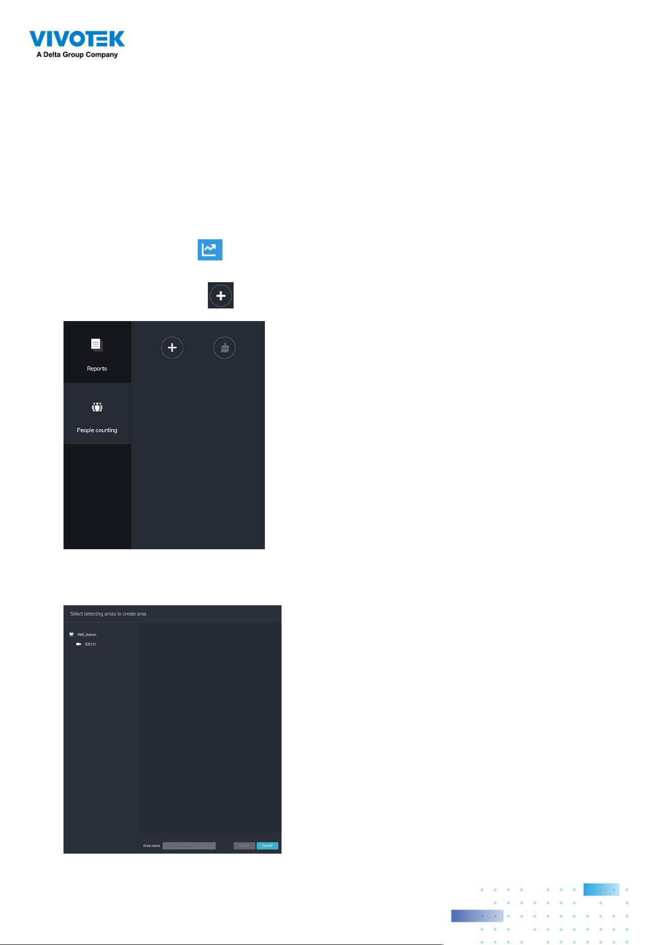
133133
4. Select a camera that is VCA-enabled, and then click the Create button.
To start VCA report:
1. Click on VCA report button on the tool bar.
2. Select People Counting.
3. Click on the Add area
button.
3. The life expectancy of VCA records is 5 years.
4. Currently the utility supports Windows XP, 7, 8, and 10.
5. The latest revision VSS supports Seamless Recording, in order to retrieve collected data
and recording during Ethernet disconnection. Provided that an SD card is installed on
the VCA-enabled cameras, the VSS station gradually retrieves data from the SD card
after the connection is restored.
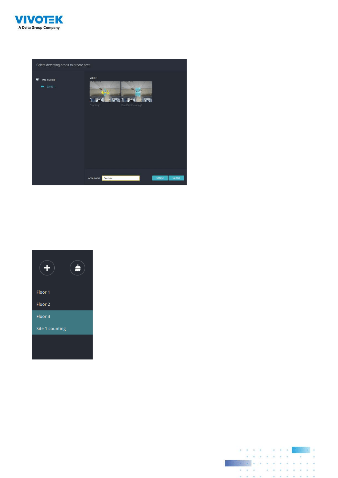
134134
5. The pre-configured counting rules (areas) will automatically display. Select a counting
rule and enter a name for the area. When done, click the Create button.
If only one camera is selected, its name will apply as the Area name. If not, enter a name
for the area.
6. Click to select one or multiple areas. Those selected will be highlighted in a different
color.
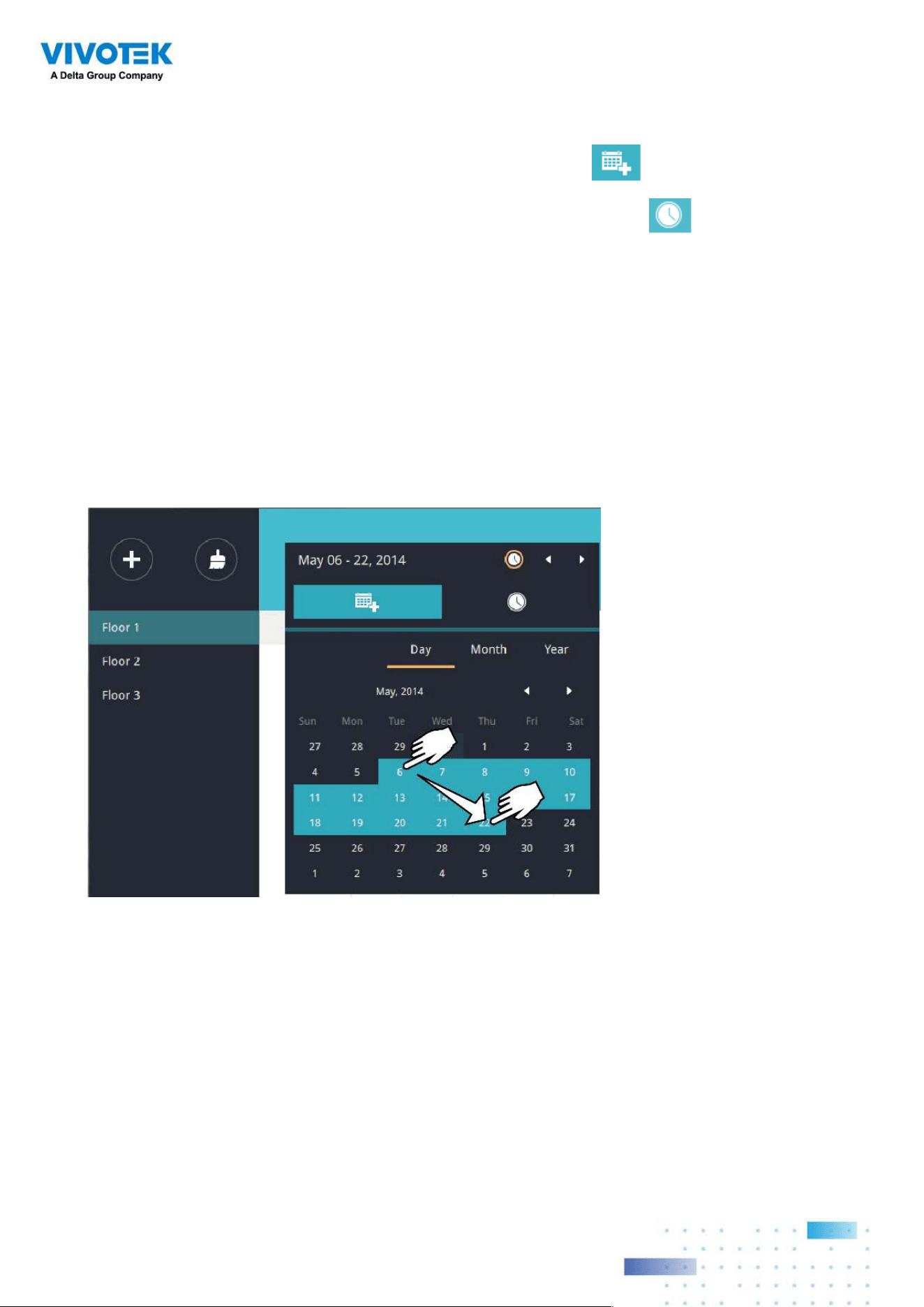
135135
7. Select Date & Time
7-1. By default, the time displayed on the calendar is the current system time on the client
computer running the utility. Select from the Date selector
on top.
7-2. Select a date or span of time from the calendar or use the Time
selector to select
a span of time.
> Single-click to select a date or click and drag to select multiple dates.
> You can select a month or a year using a single click. If you select a month, the timeline
unit will be days within the month. If you select a year, the timeline units will be the
months in a year.
> In the Month or Year panel, single click to select the entire month or an entire year.
Double-click to select sub-units, e.g., days within a month. If you double-click on a
Month panel, you will enter the Day panel.
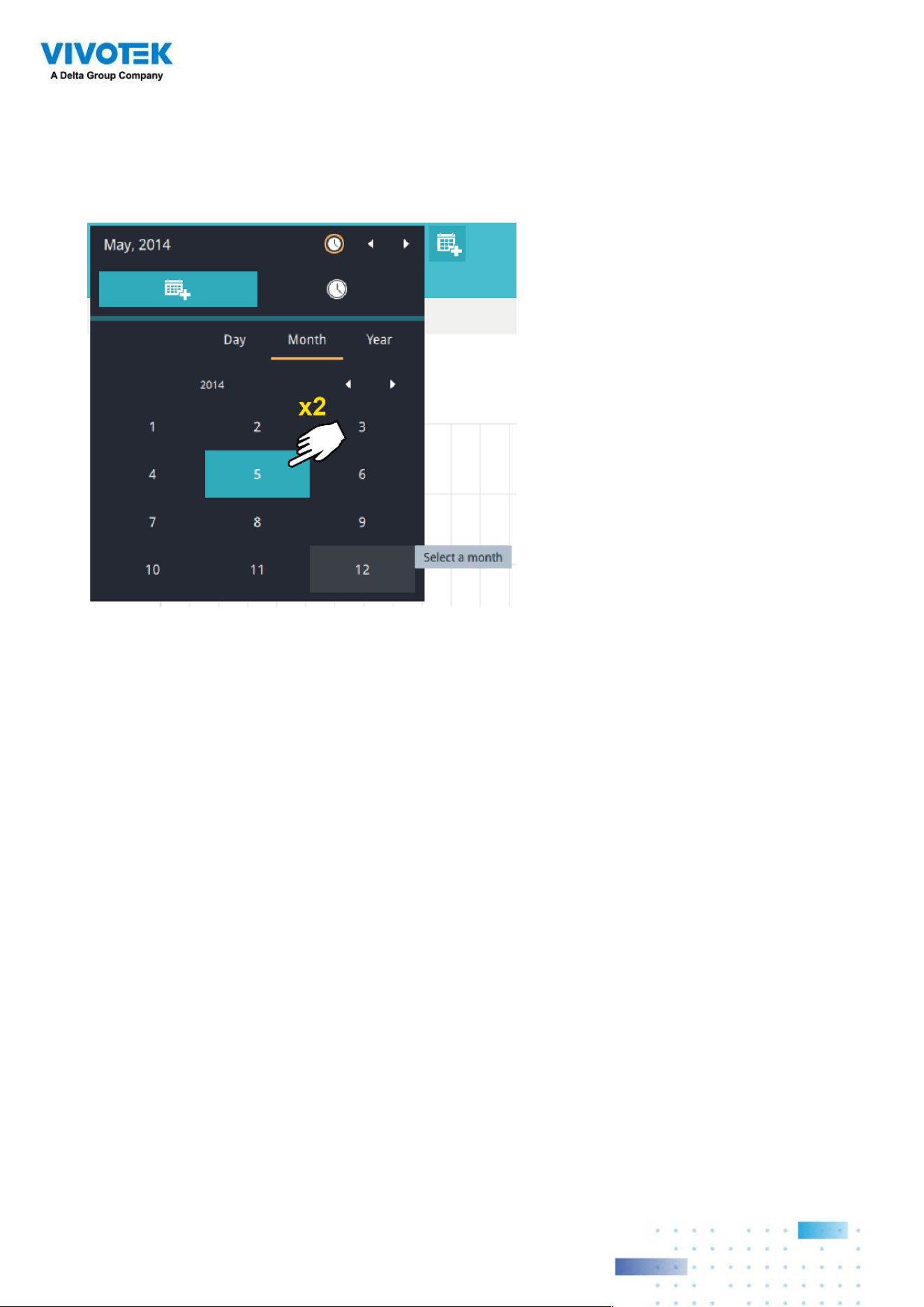
136136
You can select a different month in the Month or Year panels. The Calendar panel
disappears if left unattended for 2 seconds.
On a Month panel, double-click to select a month, and the Day panel for that particular
month will display.
Note the following when making the configuration:
• When a date is selected, the Date and Time panel will not automatically close, and the
configuration changes will not take effect until it is closed. You can click on the outside
of the panel to leave the panel.
• You can select multiple days to form a span of time. Select one date with a single click
and select multiple dates by draging your cursor across the screen to an end date you
prefer.
• To select a year, click to open the Year panel. Single click to select a year. Multiple years
can be selected using the click and drag method.
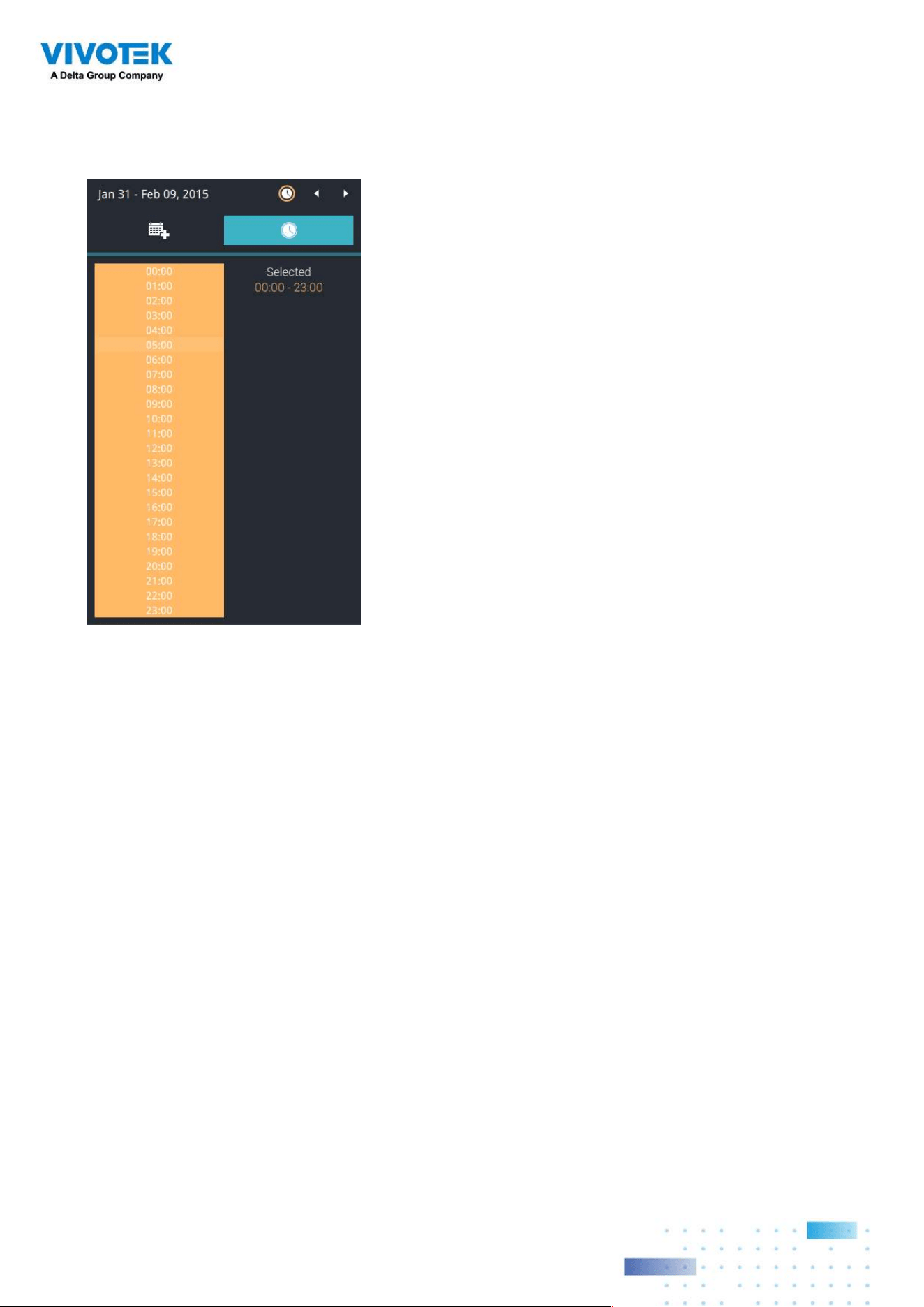
137137
7-3. Select the hours to be included in the statistical poll using multiple clicks on the chart.
Single-click to select an hour or click and drag to select multiple hours.
Note that you can only compare the counting results from two spans of time if you select
only one Area. If you selected multiple Areas, you can not compare the results from
multiple time spans.
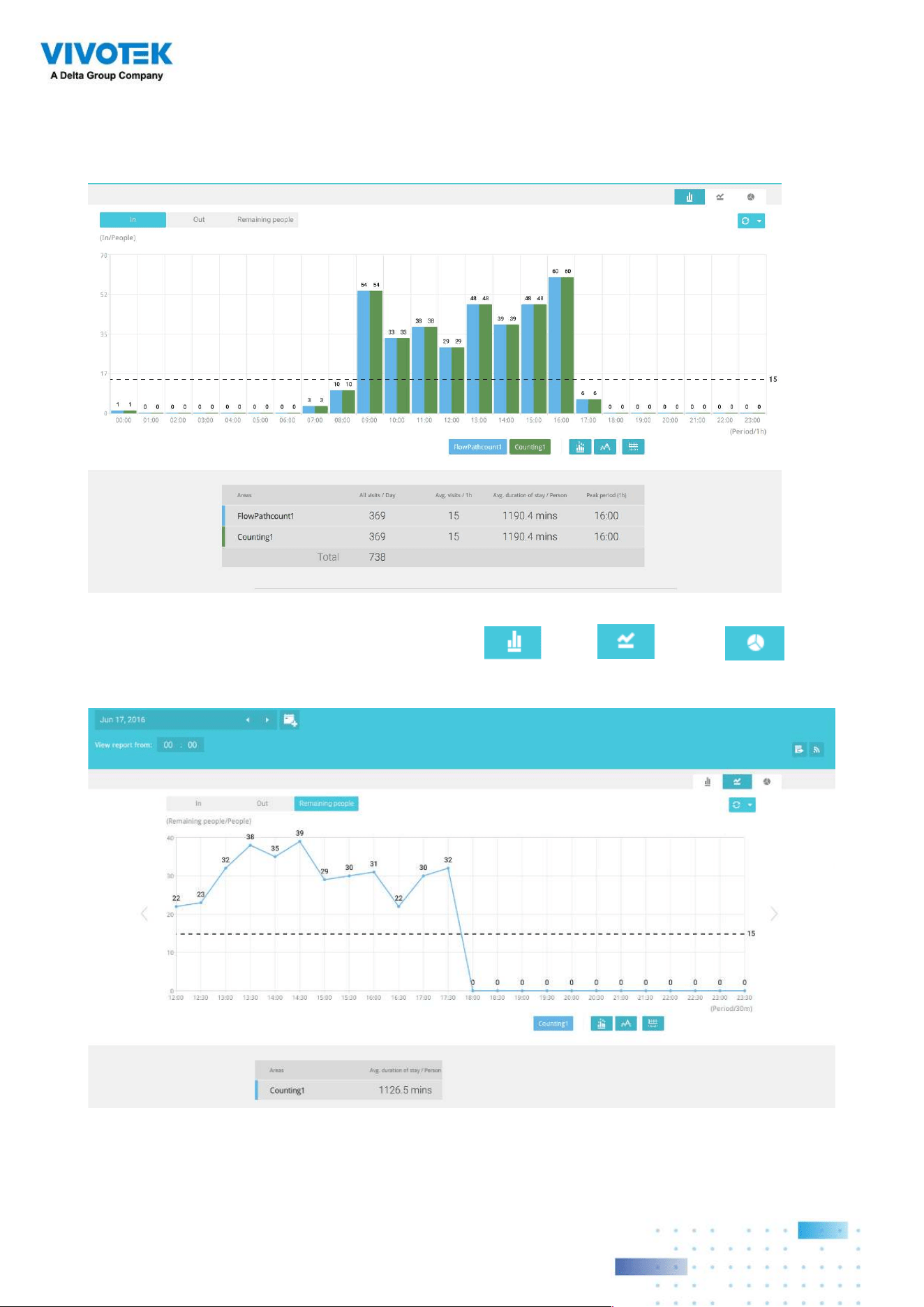
138138
7-4. Click outside the Calendar panel. The statistical results will display. The default display
is the bar chart. Below is a sample screen showing the results polled from 3 areas. Up
to 8 areas can be selected in one view.
Select different display modes using the Bar , Line , or Pie chart
buttons.
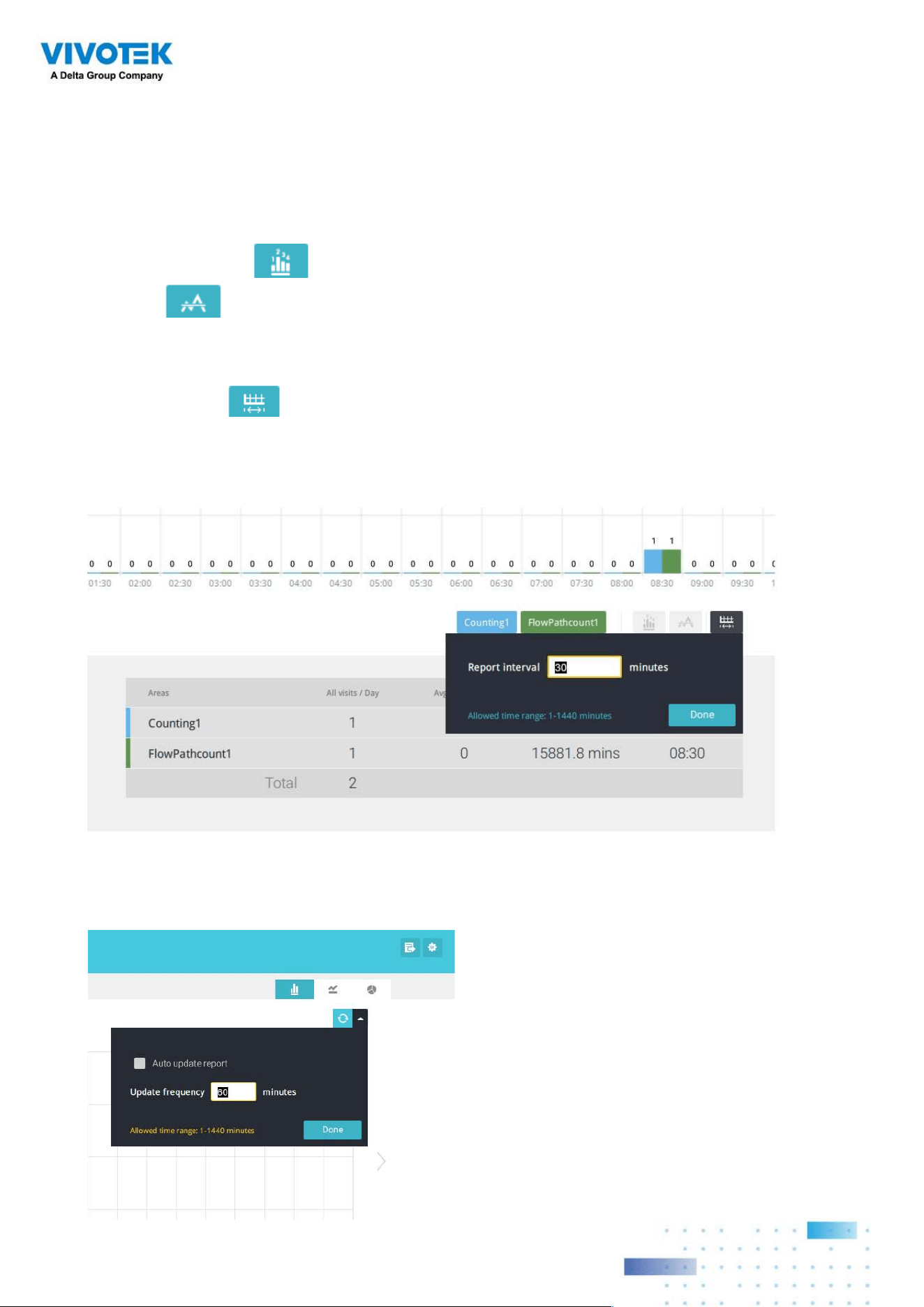
139139
Note that the timeline units can vary depending on the span of time you selected on the
Calendar panel. If a date was selected, hourly data will display in chart. If a year was
selected, monthly data will display in chart.
Use the following functional buttons to change the display parameters
Show data on chart : Displays the collected numbers on chart.
Average : Displays the average number per time span unit (e.g., per hour). If the
interval is changed to 30 mins, the average number will be halved comparing to the number
acquired by every hour.
Report Interval : Configure the intervals for polling data from the camera. The
default for displaying results is by every hour. If you enter 30 minutes as the display
interval, all data will be listed on the basis of the 30 minutes time span. The configurable
range is 1 to 1440 mins.
You can use the update menu on the side of the Refresh button to determine an automatic
update schedule. You can let the statistic chart update itself by a regular interval.
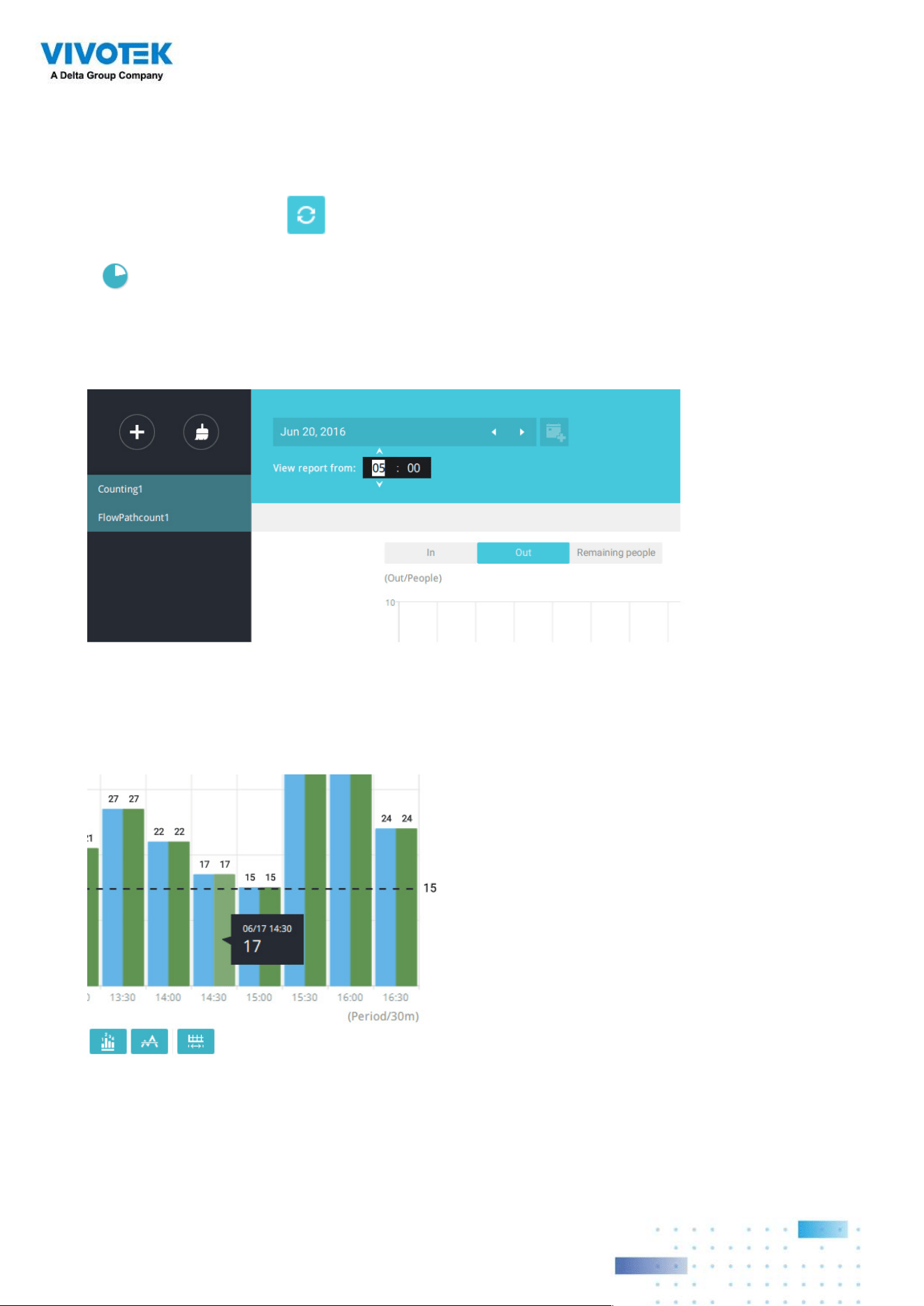
140140
Use the Refresh button to poll the latest data from camera.
Use the time selector on the View Report from pane to select the start time of your
statistics view window. Data collected before that time will not be displayed.
A number is displayed when you mouse over an area on the chart. Move your cursor to an
area on chart, and the number is displayed.
If you selected only one area, you can use the Shift key to select multiple areas (or two
spans of time). You can select multiple dates in the Calendar panel.
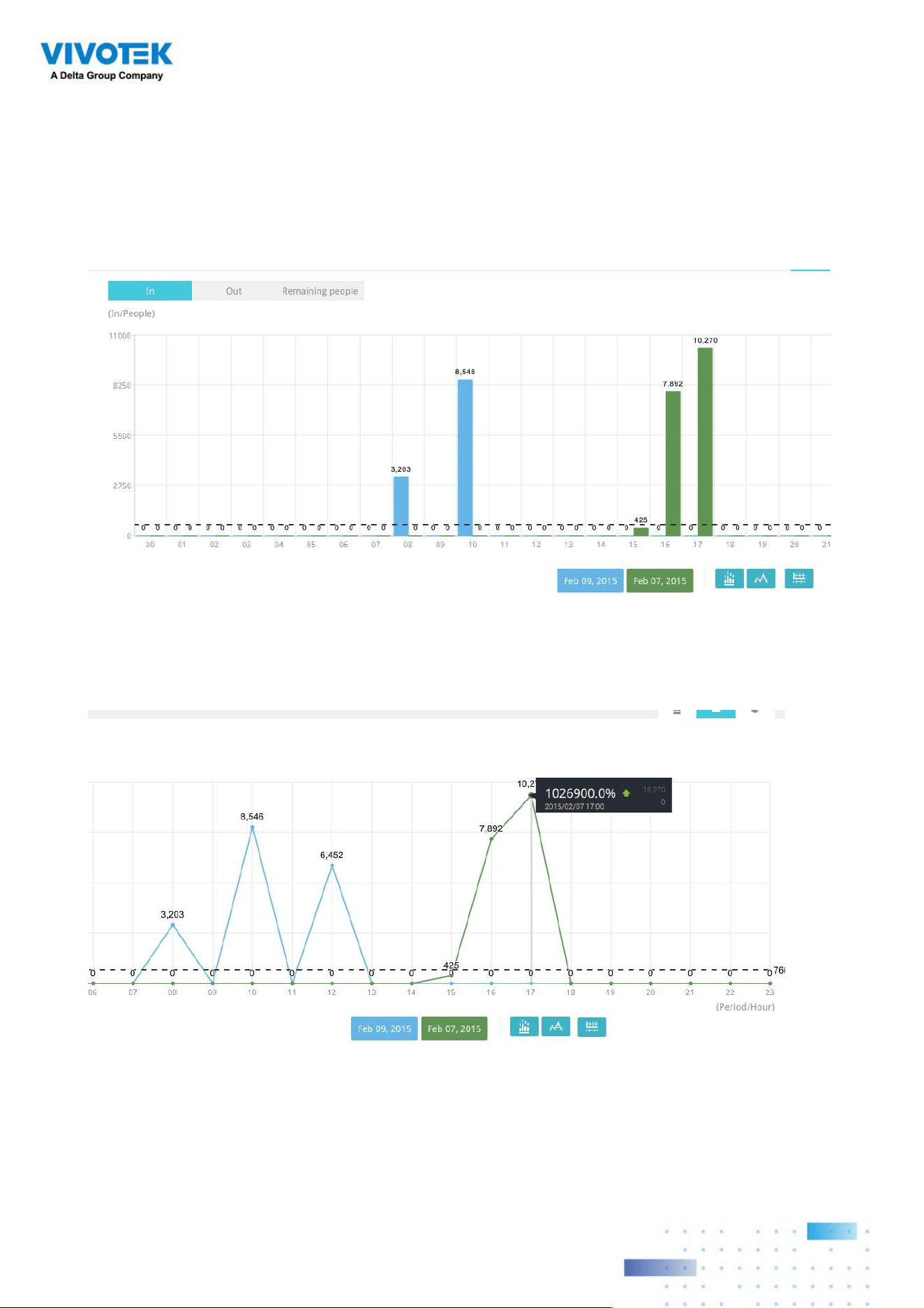
141141
Data on a time line will be generated. To close the window, use the close button on the
second date information. Equivalent spans of time can also be used for comparison. For
example, you can compare the data in a span of 4 days against another span of 4 days.
Note that the Compare function only applies when you select to display only one area on
the screen.
In a comparison result displayed in a line chart, mouse over to the peak value to display the
percentage of an increase or decrease rate.
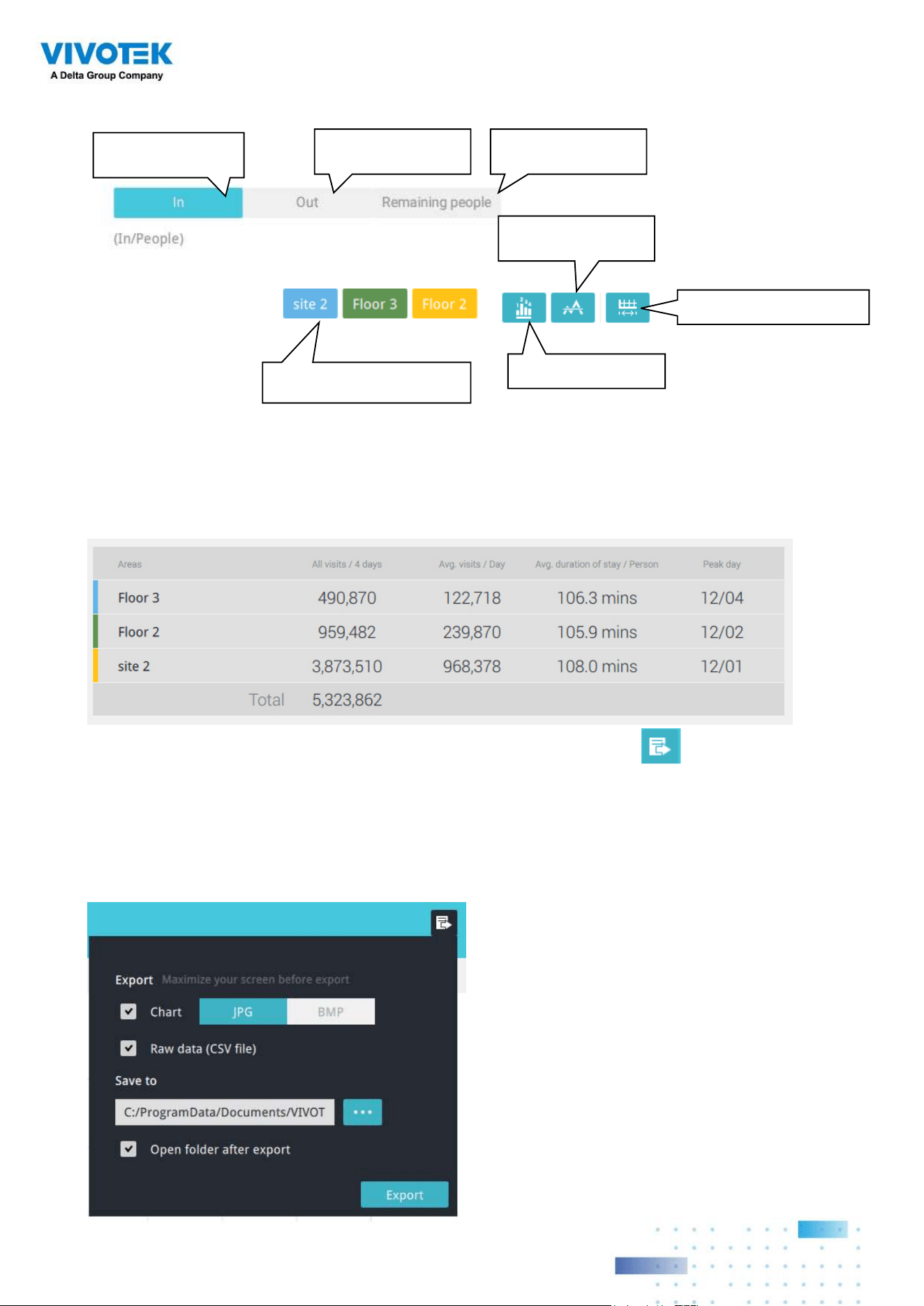
142142
See below for the functions of buttons on screen.
Click to display or
hide the results for an area
No. of people who
entered the area
No. of people who
left the area
No. of people who
remain in the area
Show an average
number
Show data on chart
Change the report interval
In addition to the charts, a summary of displayed data will be listed below showing the
areas involved, visits/Day or Month, Average visits / Hours / Days, Average duration of stay
/ person, and the Peak hour.
8. When done with displaying the results, you can use the Export button to produce
an image le to preserve the current results. Both a spreadsheet and a graphic chart will
be produced.
By default, the exported report is placed in:
C:\Users\Public\Documents\VIVOTEK Inc\VAST\Client\VCAReport
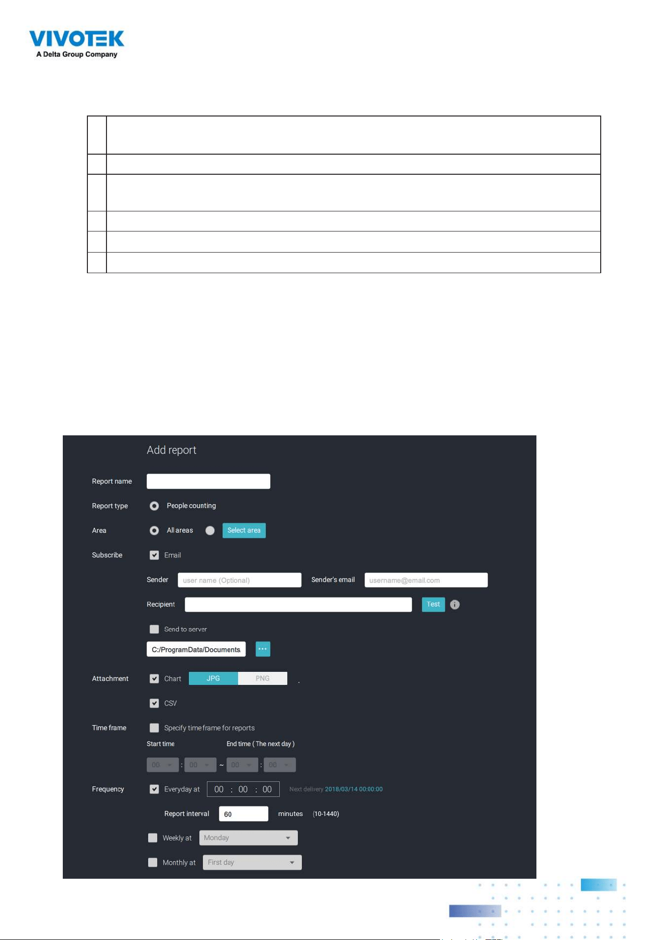
143143
9. Click the Reports Subscription button to configure the regular report sent to your Email
account or a specific location on the server itself.
Select the following:
1.
Report type: People counting results, or Heatmap (Heatmap does not produce the
CSV file)
2.
Area: All areas or a preconfigured area.
3.
Subscribe: Enter the sender and recipient Email addresses. You can also configure
to send the report to a specific location on the server.
4. Attachment: Select to attach graph Charts in JPG or PNG, and the CSV
data files
.
5. Time frame: Select the time coverage of the report, during which data is collected.
6. Frequency: Species when and how frequently to deliver the reports.
Select the time to deliver your mail notification. Enter valid Email addresses as the
sender and receiver addresses and make sure the SMTP mail server configuration has
been properly configured on your VSS server. This VCA mail notification utilizes the mail
service on VSS for regular notification. You can then receive Email notification every day
on your Email account. You can enter up to 5 recipient addresses.
Select the report interval to determine how often you receive an aggregated report.
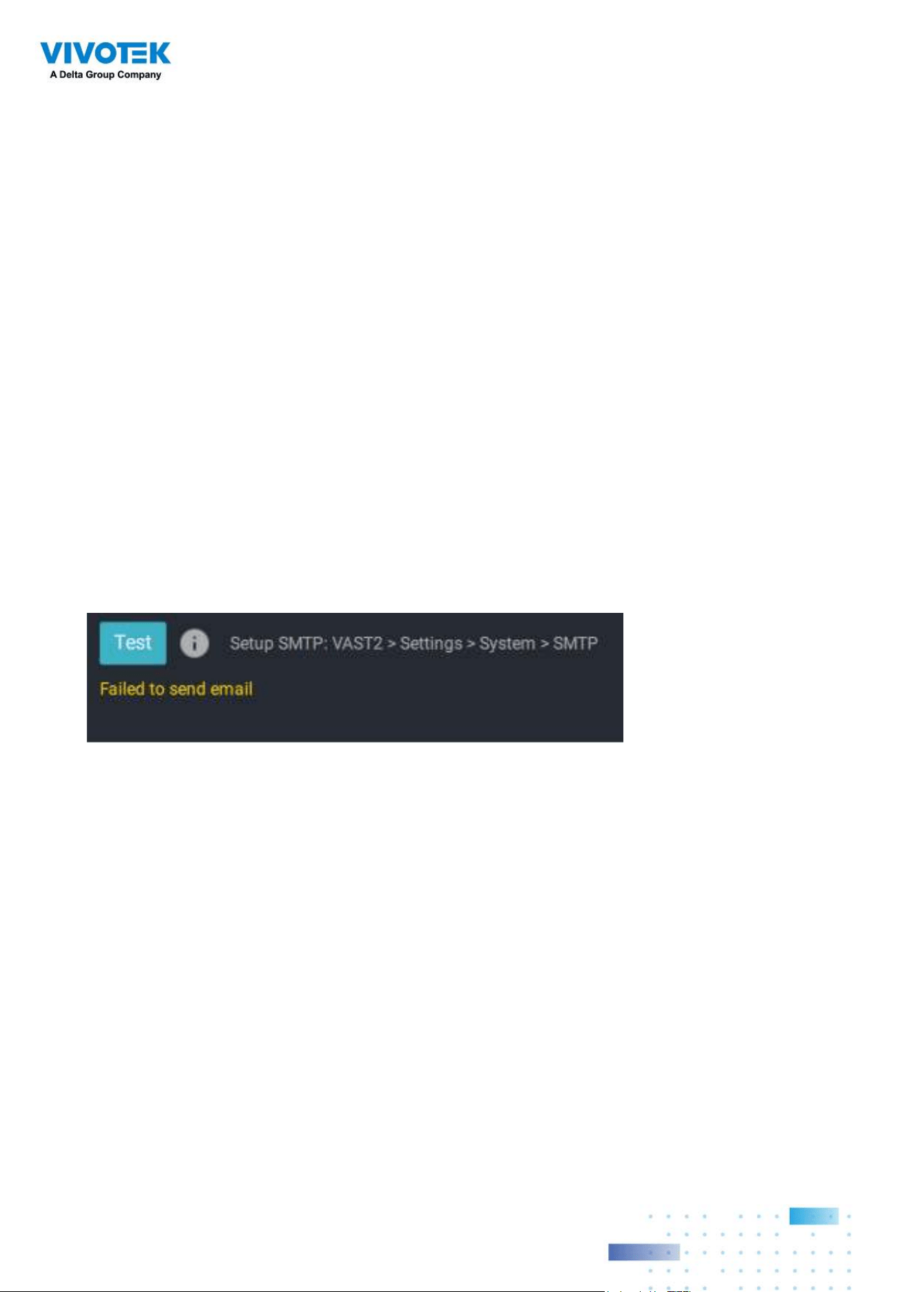
144144
Note that the notification contents is your current field of view, including a Bar, Line, and
Pie chart combined into one image file. The In/Out/Remaining results will be generated
into 3 charts. Each Area will generate one CSV file, and each CSV data file will contain
In/Out/Remaining/Summary information.
The generated file names will look like this: 20160226_test02_Remain.jpg for charts
and 20160226_Summary.csv for CSV files. The Email subject will be "VCA Daily Report -
2016/02/26."
Note that if you manually export a report, the default is sending the data collected until
one hour before the manual export. For example, if you generate the report at 14:07, the
report will only cover the data collected until 13:59. You may use the Refresh button to
manually generate an immediate data inputs (those occurred between 14:00 and 14:07).
You may configure to receive regular VCA report as Weekly or Monthly using the
associated menus.
Below are the messages with the Email test function.
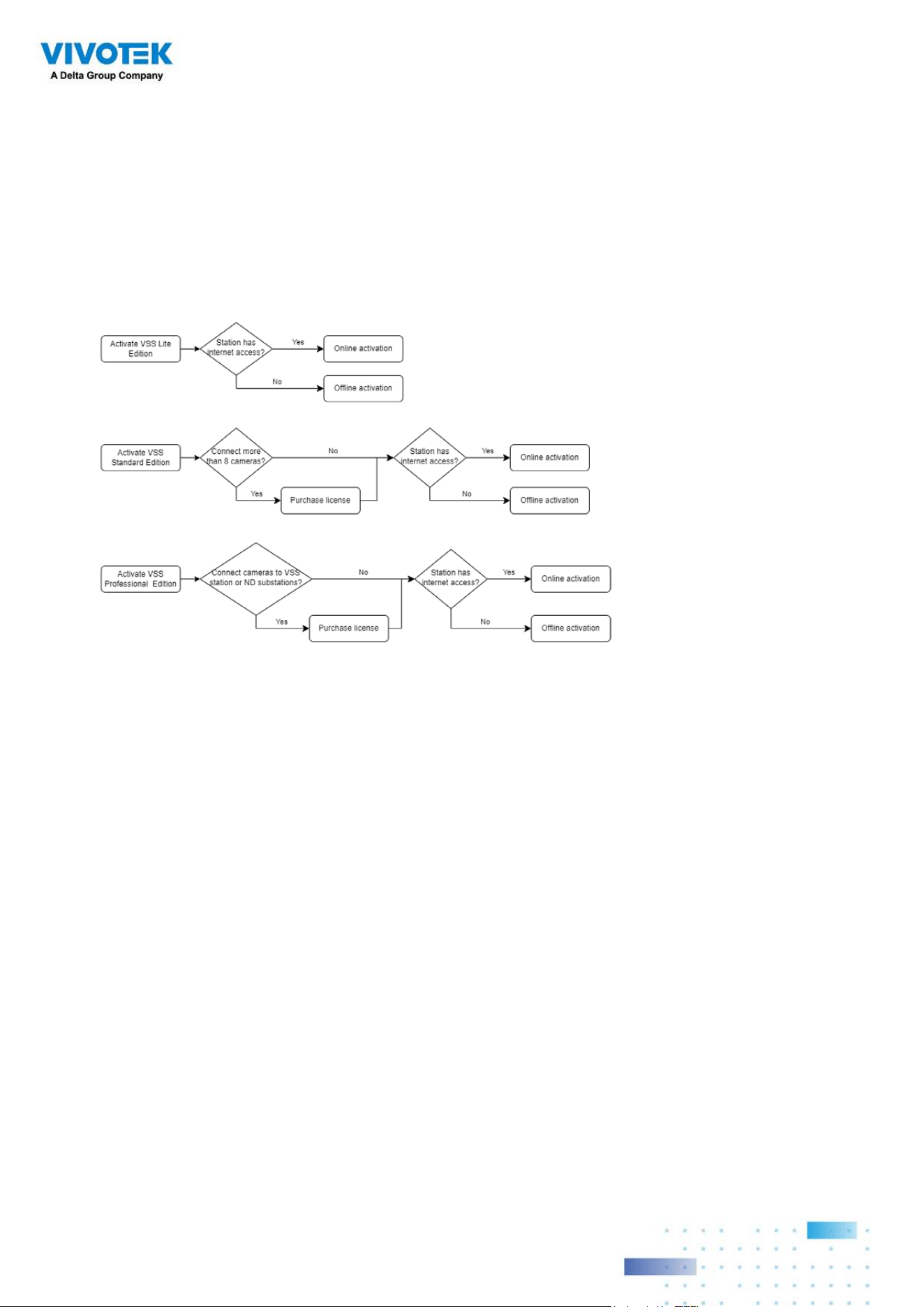
145145
3-4. VSS Software License
To activate the software, refer to the flow chart below:
After VSS is installed, a 60-day trial version will be started automatically.
Users must select one VSS edition and activate the licenses online or offline before the
trial expires. The camera live view, playback, and recording services will stop after a 60-day
trial.
Online activation
If the VSS station has internet access, activate the license using the online activation
method. The license request file of the VSS station (.req file) will be sent to the licensing
server via the internet automatically. The licensed file (.lic file) will be received from the
licensing server if the activation process is successful.
Online activation is recommended over offline activation. However, if online activation
fails or internet access is unavailable, see Offline Activation in the next section below.
Steps:

146146
The edition menu will show you if you are required to purchase licenses to activate each
edition based on your current VSS deployment.
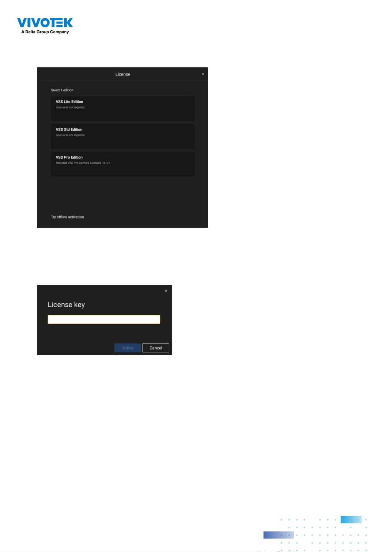
147147
If the purchased license is required, a license key window will pop up after you select
the edition. Type in the license key you purchased and acquired from your distributor or
VIVOTEK local sales and click Activate, then the activation process with the licensing
server will begin.
If the purchased license is not required, click on the edition, and the activation
process with the licensing server will begin.
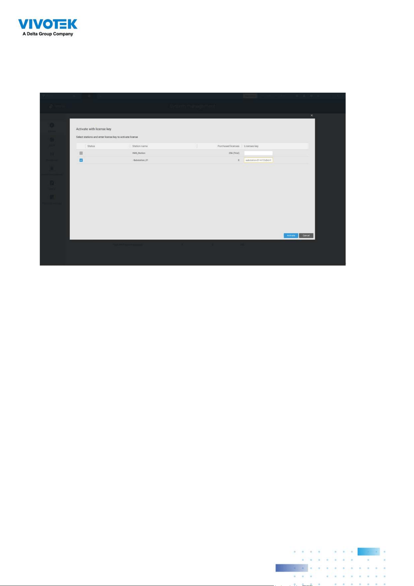
148148
If you select Activate with license key, slect the station where the license key will apply to.
Enter the license key.
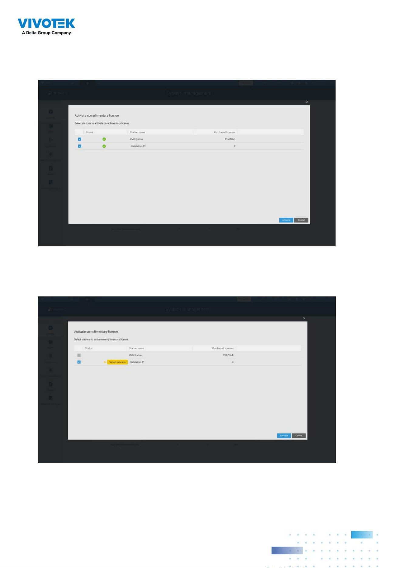
149149
When successfully activated, the associated check circles will turn grren. Click the Close
button on the upper right of the screen.
If you fail, status bar will turn yellow with an alarm icon, and the possible reason will be
listed.
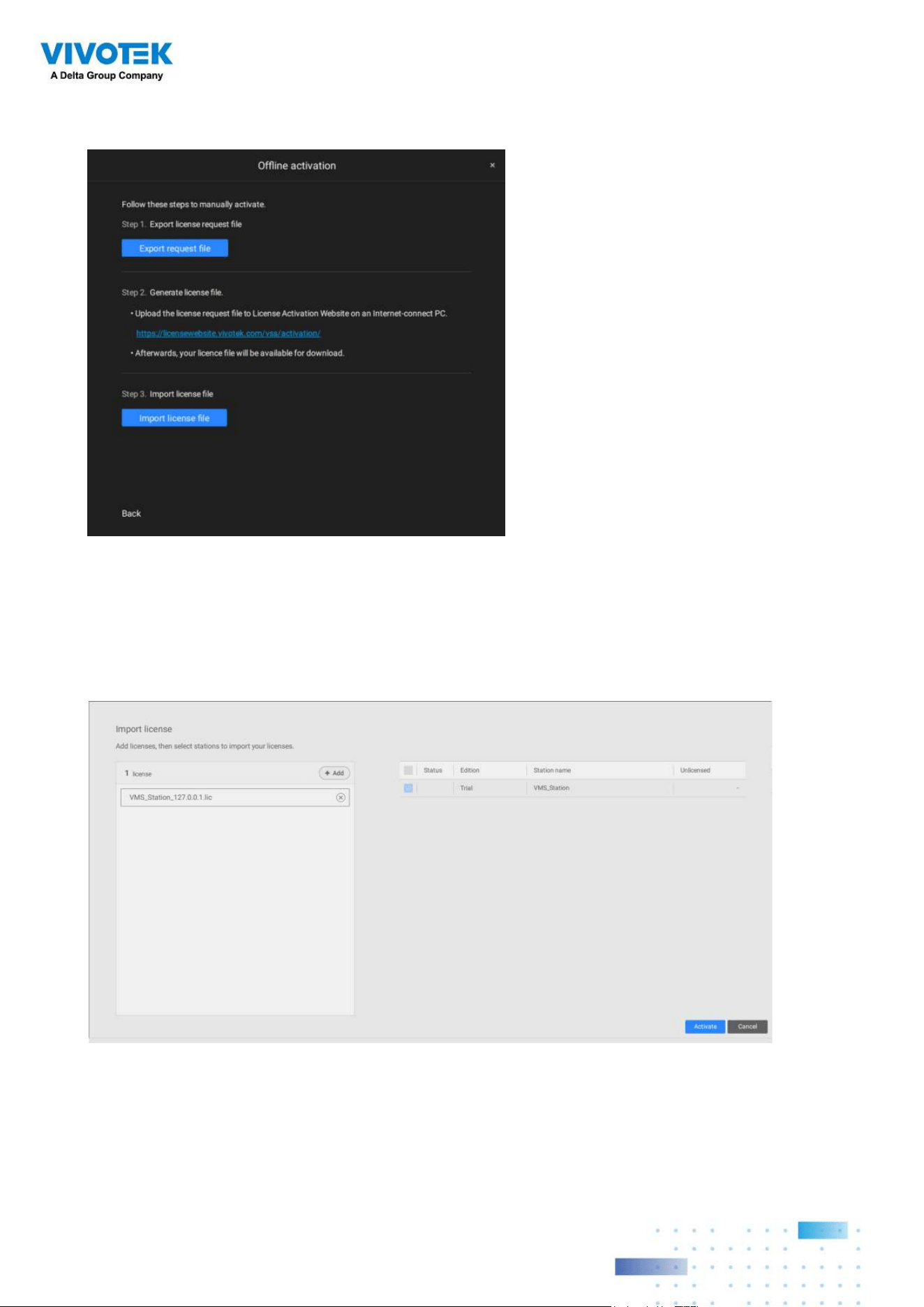
150150
If your VSS station has no Internet connetion, Click Try offline activation.
According to the instructions on screen,
1. Export licensse request file.
2. Select the station to export the license request, click Export, and select the destination
of the request file.
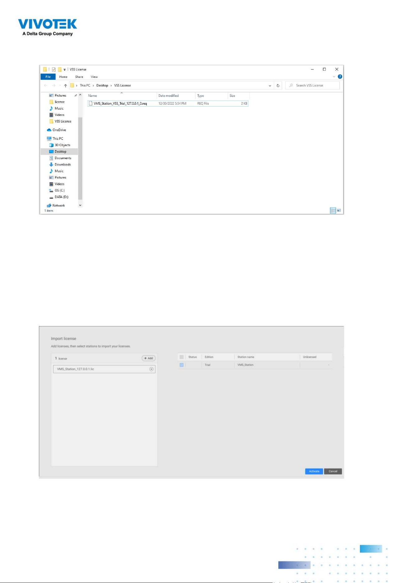
151151
The REQ file looks like the following.
3. Find a computer to upload the license request file (.req) to VIVOTEK's license activation
portal at https://licensewebsite.vivotek.com/vss/activation/.
4. Follow the instructions on the license activation portal to generate and download the
license file (.lic). Upload or copy the file to your VSS station.
5. Go back to the offline activation window on your VSS station, select Import license file,
click Add to select the license file (.lic) and click Activate.
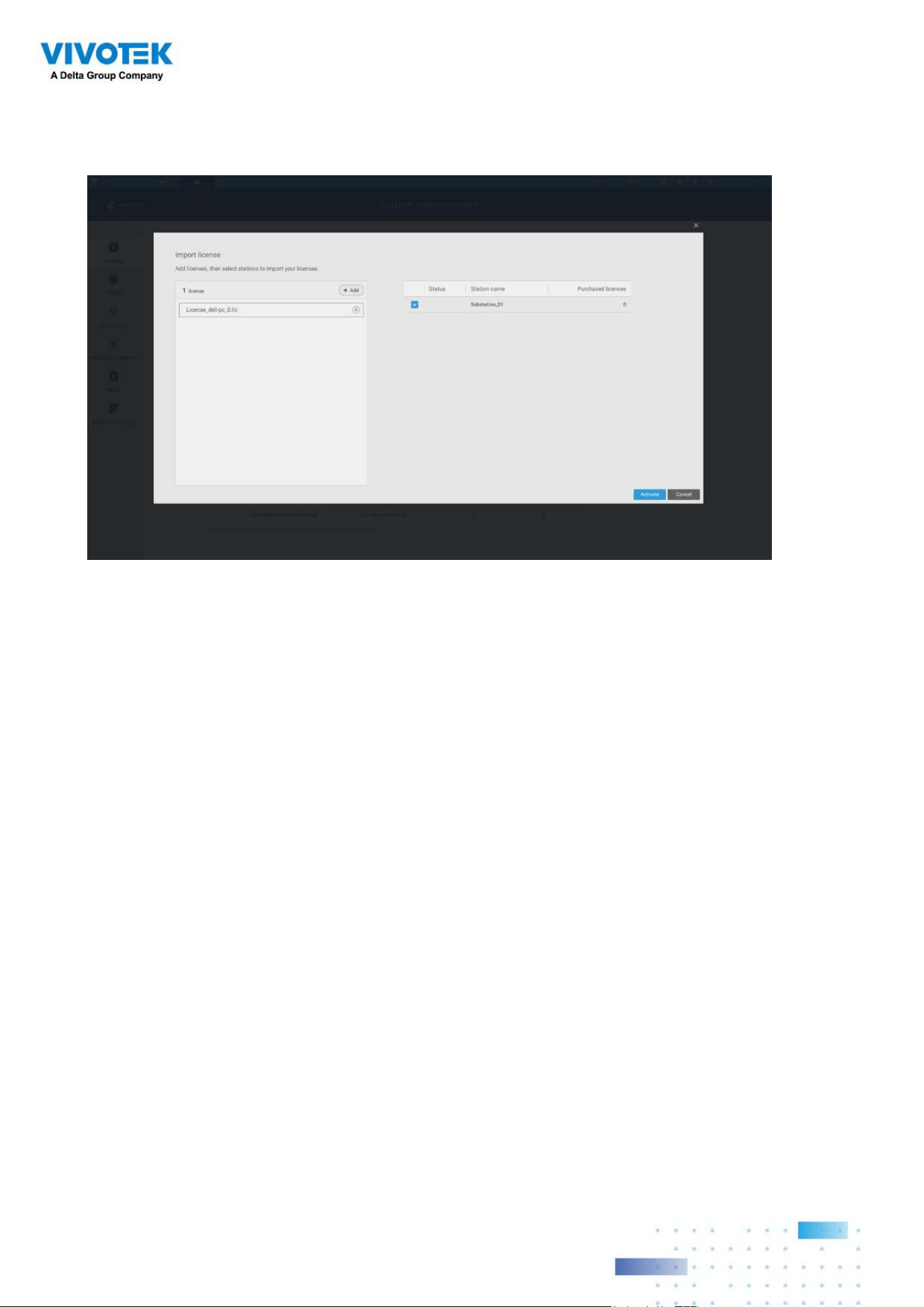
152152
5. On your VSS station, select import license file, click Add to select the license file (.LIC
file), and click Activate.
License Protection Mechanisms
The software license is verified by identifying the unique characteristics of the user's
PC. The license file contains data on the VSS station’s basic hardware configuration
(Motherboard, CPU Processor, Graphics Card, RAM, and Network Card). The software
license will become invalid if the user changes any three of these essential hardware
components.
NOTE:
• Keep a copy of the license key, license request file(.req), and license file (.lic) for future
reference.
• Without sufficient licenses, the camera live view, playback, and recording services will
stop in 14 days.
• VAST1 license, VAST2 license, and dongle license are incompatible and unable to use as
the VSS license.
• An identical software license applies to VIVOTEK and ONVIF cameras. You do not need to
activate two different kinds of software licenses.
• If the VSS server application is removed and re-installed, the number of licensed channels
remains intact.
• Users can upgrade the VSS edition by activating appropriate edition licenses.
Downgrading the edition via the license is not supported.
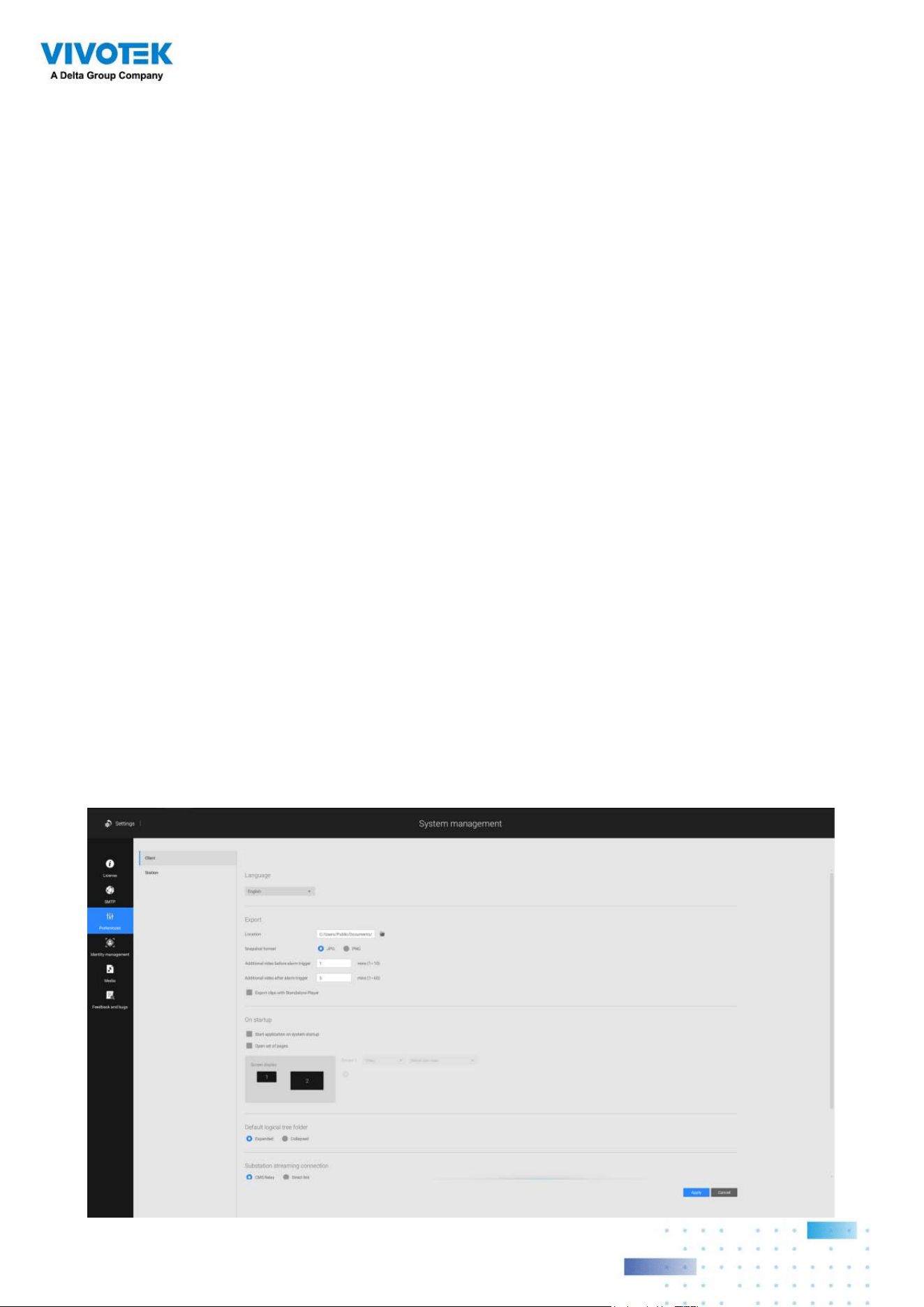
153153
Chapter 4 Settings:
4-1. Settings > System >
Preferences
The Preferences page for VSS client and Station sides allows you to configure the
following:
Client Setting:
1. Select the UI text language.
2. Configure a default destination for exporting video, snapshots, or configuration backups.
The default is "
C:\Users\Public\Documents\VIVOTEK Inc\VAST\Downloads". You can
change the media format via the checkboxes.
3. Select the format for the snapshot as either JPG or PNG.
4. You can select the length of the Alarm-triggered videos by specifying pre- and post-
alarm recordings.
5. You can designate the VSS client interface to automatically start once the client
computer is started.
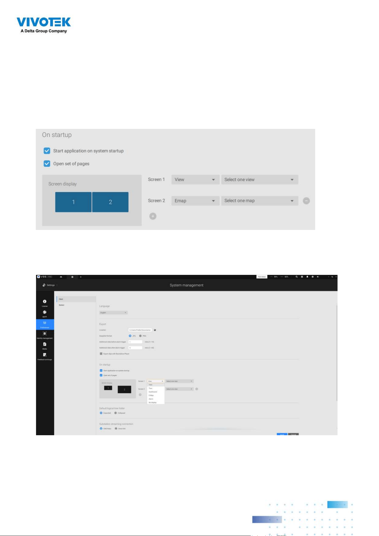
154154
6. The default Live view, which may span across multiple monitor screens and display Live
view, Tour, Dashboard, E-Map, or Alarm prompts. The precondition is that you should
configure one or many views before making the Startup configuration.
Below is a server/client with dual monitors, you can select one view to be displayed on
one monitor, or place an E-Map on another.
Click the Apply button for the configuration to take effect.
If you plan to have one monitor to be working for other purposes, select No display for
this monitor.
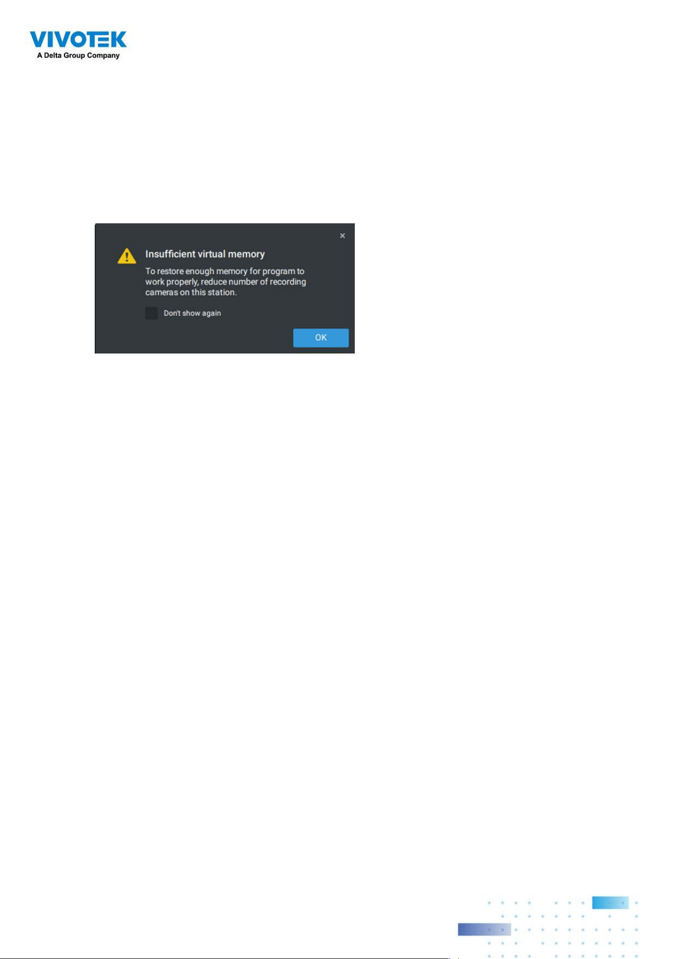
155155
Below are the additional system parameters:
Default logical tree folder: Expanded or collapsed.
Substation streaming connection: CMS Relay or Direct link. Direct link allows a client
station to access camera live stream from the sub-station under a CMS main station.
CMS relay
-
A client accesses live stream via the CMS main station.
Show system warning: When
a client computer is running short of virtual memory, a
warning will display.
Image resamplig method: Select a resampling methold if the need should arise.
Click the Apply button for the configuration to take effect.
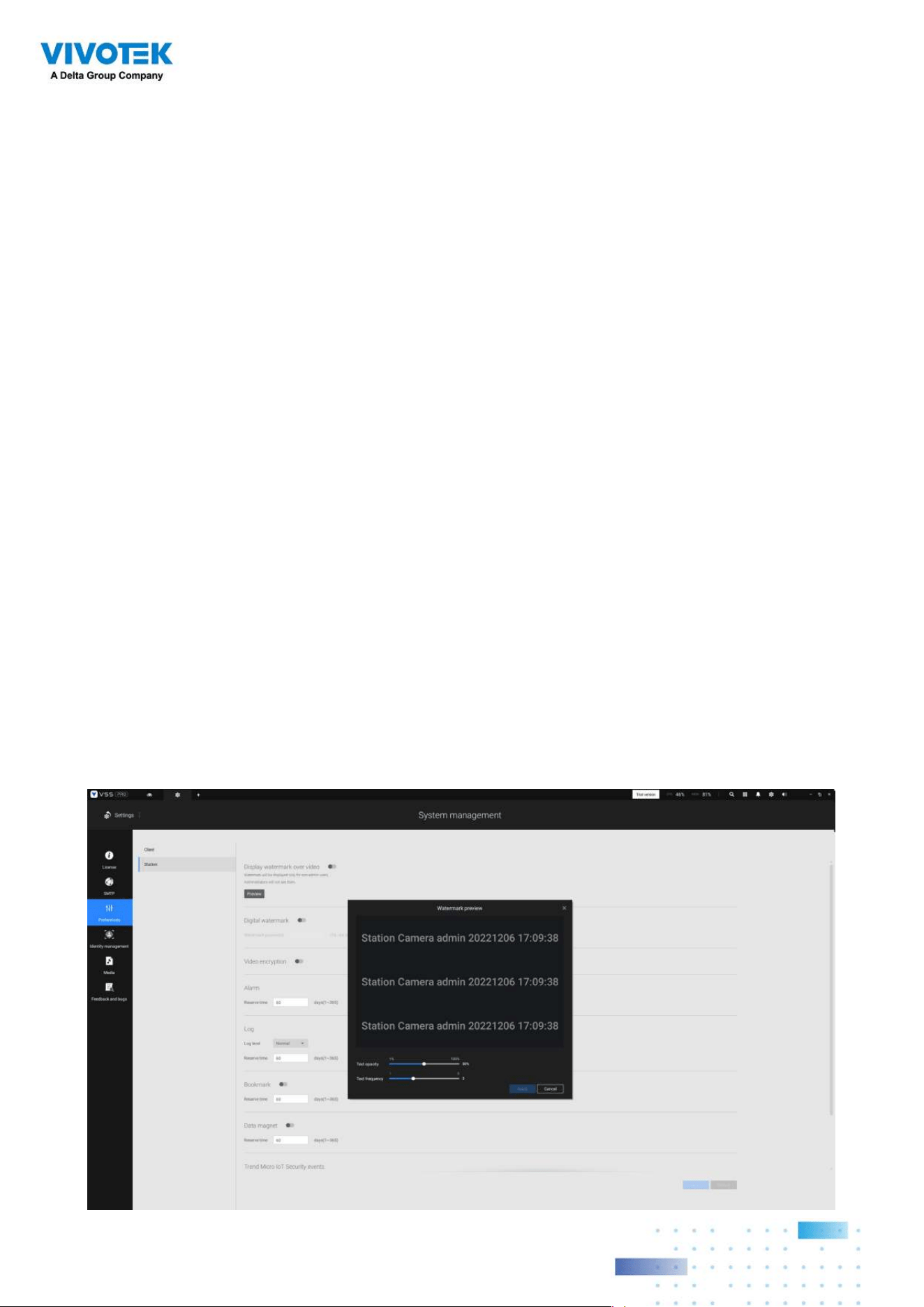
156156
Station Setting:
1. Display Watermark over video - Administrators can select to display watermarks on the
video feeds of the VSS clients. The opacity and display frequency can be adjusted.
Encrypted watermark for authentication:
To ensure your video is authentic and has not forgerized, adding an encrypted
watermark on the data stream can be achieved with a customized password. You
can use the Standalone Player to verify which frames in the video footage have been
tampered with.
If enabled, the following will be displayed:
camera name + substation name + VSS user
name + user computer current time
. The purpose of watermark is to preserve evidence
if the video screen is recorded using cell phones or other devices.
Station Setting:
2. Digital watermark - To prevent forgery of recorded or exported video clips, and to prove
the validity of surveillance evidence, digital watermark can be appened to recorded
video.
Note that only non-administrator users will see watermarks.
To enable text watermark, use the slide button. Use the Preview function to tune the text
opacity and text frequency display on screen.
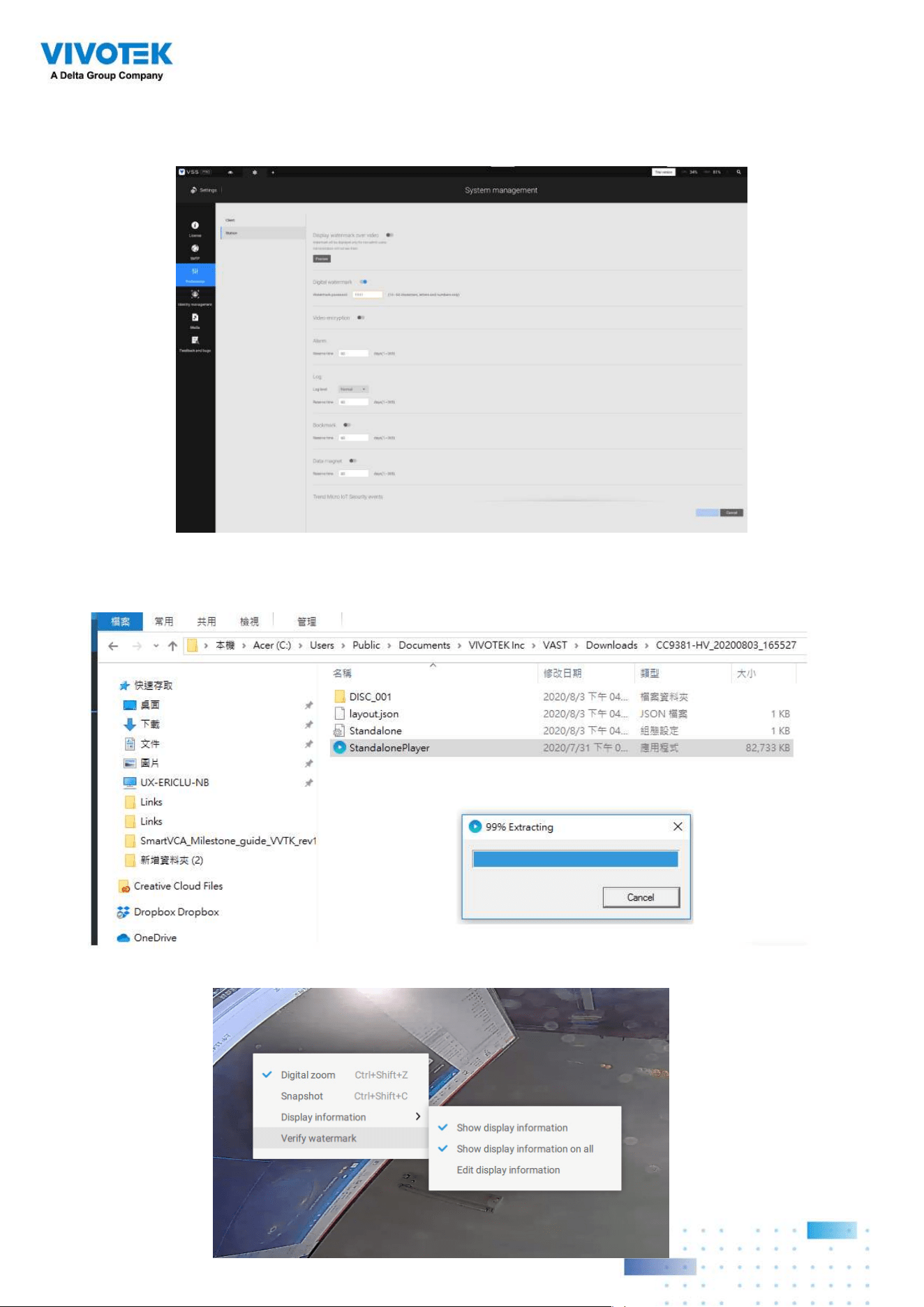
157157
To enable Digital watermark, enter a password that is at least 16 characters long. Once
a valid password is available, you can click the Apply button to preserve your setting.
When you export a video clip, a StandalonePlayer is generated with the exported files.
Right-click on the StandalonePlayer screen to display the "Verify watermark" function.
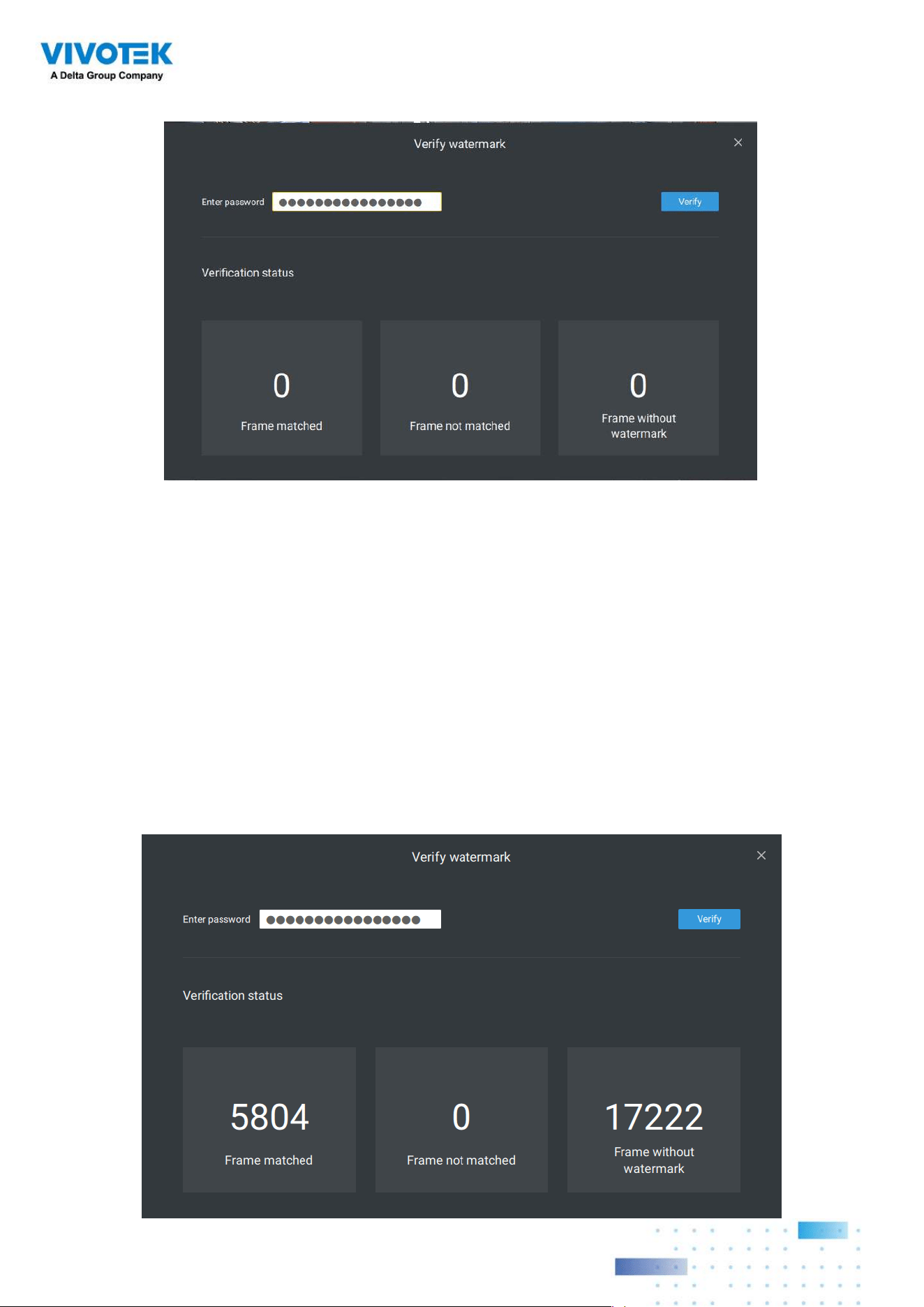
158158
The Verify screen will display. Enter the pre-configured password. Click Verify.
The below result shows that the video is authentic and has not been forgerized.
Frame matched: Your video was exported with the digital password, and you entered the
correct password.
Frame not matched: Your video was exported with the digital password, and you entered
the incorrect password.
Frame without watermark: a. If your video wasn't exported with the digital password.
b. If your video was exported with the digital password, and your video has been
tampered.
If the numbers in the "Frame not matched" or "Frame without watermark" are not zero, it
means your video is probably not correct.

159159
3. Alarm - Reservation time: Configure the preservation time of the alarms and logs. Note
that some alarms can be triggered with recorded videos. Configuring a preservation
time can help reduce the use of storage space on server.
4. Log: Use the menu to configure the preservation time of the Major, Normal, or Minor
logs.
5. Bookmark: Configure the days of preservation for bookmarks.
6. Data magnet: Configure the days of preservation for data related to Data Magnet.
7. Trend Micro events: Configure the days of preservation for events related to cyber
security.
8. Database: Configure the destination of the database folder. The database contains
information for system log, alarms, Bookmarks, data magnet, VCA reports, POS
transaction data, snapshots, and Trend Micro IoT security information.
Recording Encryption - Recording encryption allows users to encrypt the recording
videos with password protection. Playing the encrypted video on the original VSS
server does not require entering the password.
Playing on other VSS servers or disabling recording encryption will require entering
the password. The password is not able to recover or reset if you forget the original
password.
Encrypted video files (.3gp) cannot be played in other media players. Please use the
following two methods to view the video files outside the original VSS server.
1. Import to other VSS servers as Local DB
a. Copy the entire recording folder from the original VSS server to another location.
b. Enter Settings > Recording > Local DB in another VSS server.
c. Add local DB with VMS/CMB backup type.
d. The recording will be mounted as a local DB and listed sub-tree.
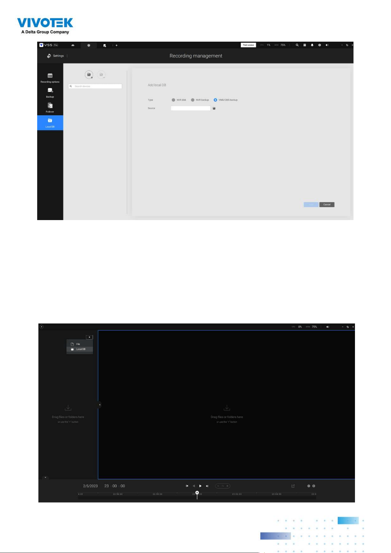
160160
2. Import to VSS Standalone player as Local DB
a. Copy the entire recording folder from the original VSS server to another location.
b. Launch Standaloneplayer.exe in C:\Program Files (x86)\VIVOTEK Inc\VAST\Client\
VSS\
c. Add local DB with VMS/CMB backup type by dragging the entire recording folder or
using the “+” button.
d. The recording will be mounted as a local DB.
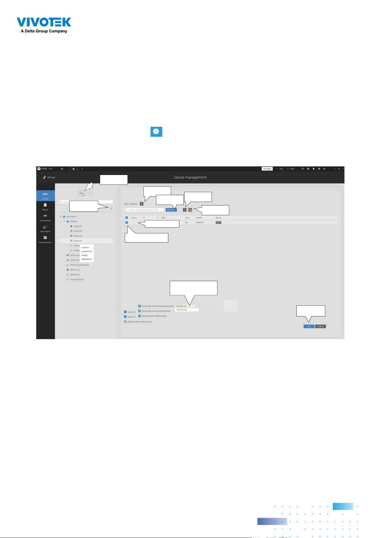
161161
4-2. Settings > Device >
Cameras
In addition to the add device process during the initial setup, you can add more cameras or
arrange the device list in Settings > Cameras.
Below are the locations of the functions for adding devices to the VSS server.
Start Scanning
Import CSV
Manual Add
Refresh
Authorize...
Click to select or deselect
Password protected
Edit device list &
Logical folders
Final confirm
Camera Options
Note that you must know the credentials for password-protected cameras. You will not be
allowed to enlist cameras that come with unknown credentials.
For cameras outside the local network, you can manually enter its IP address, or use a pre-
configured device list to automatically introduce new devices.
If all devices come with the same credentials, you can select these devices and click
Authorize to enter the credentials.
Record video with recording management: You can decide which recording group to
record the videos to using a pull-down menu.
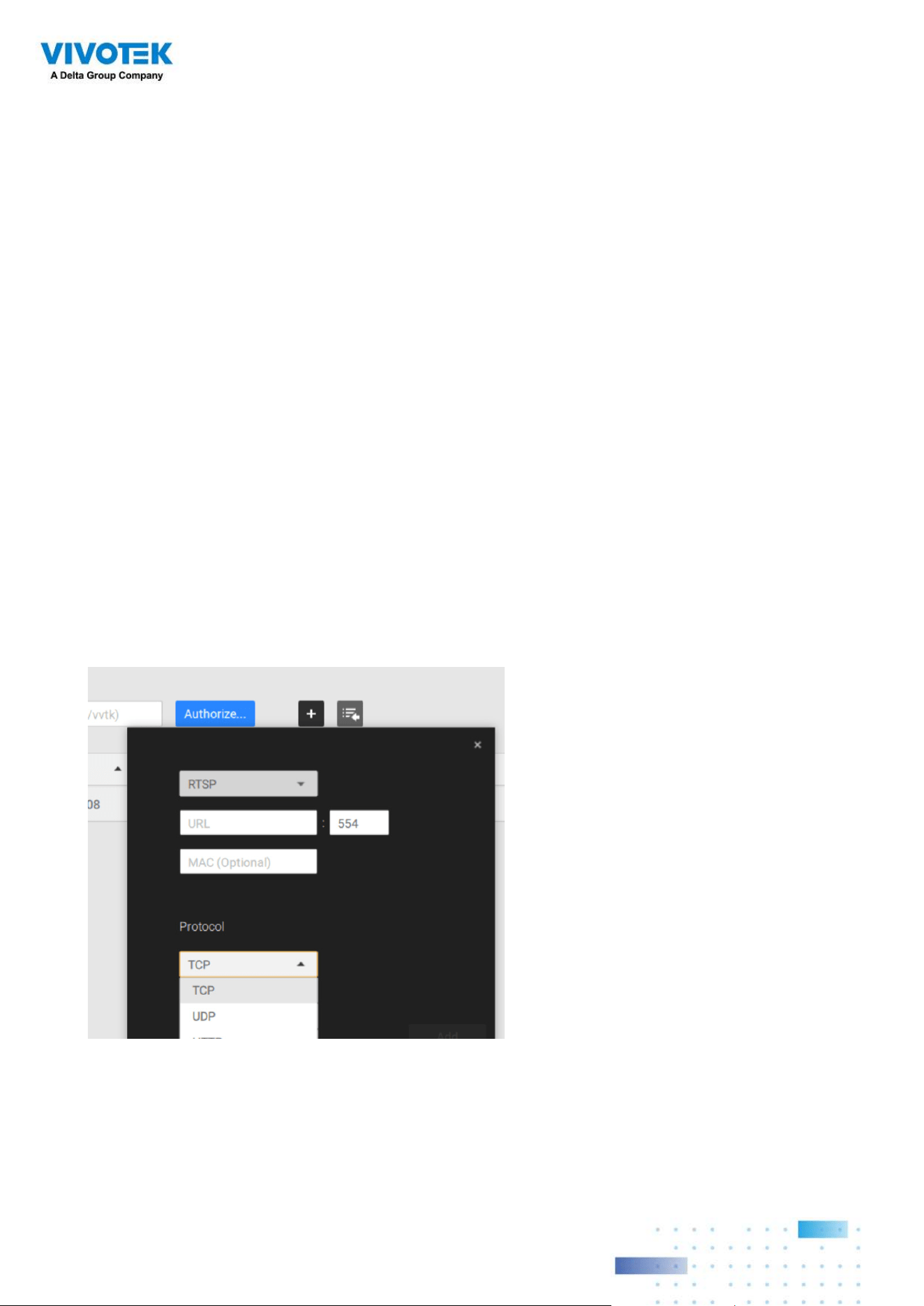
162162
Streaming URL
This is an optional feature. You can enter a camera's IP address to add a camera's RTSP
streaming for live view and recording, and playback. The feature enables the support for
obsolete models.
To insert a camera using the URL-like command,
1. Select the camera Brand as "
RTSP
."
2. Enter the camera's IP address.
3. Enter the camera's MAC address as printed on the camera label, or one found by the
Shepherd utility.
Retrieve RTSP streaming on specific port: The default port for RTSP streaming is 554.
If you want to change this port, please check this item and fill in a desired port number.
Speed up (add as offline cameras): Normally, you should have all the credentials for the
access to all network cameras. However, in the condition that you add a large number of
cameras using the "import devices from device list" function, you can temporarily use this
speed up option to add these cameras.
This appllies when the cameras have not been installed (have been prepared for
installation), but you want to add them to the camera list. When cameras have all been
installed, VSS will attempt to connect with them.

163163
6. For administrators who need to synchronize device time with a NTP server, he can
deselect the "Synchronize camera time with system" checkbox.
4. Enter "554" in the Conguration port.
5. Enter "live.sdp" in the URL eld, as this is part of the original RTSP streaming command:
"
rtsp://172.18.204.58:554/live.sdp". If streaming stream #2, enter live2.sdp.
6. Select a preferred protocol.
Only the live view, recording, and playback functions are supported if thus connected.
All other functions are not supported, such as auto streaming size or changing to
another video stream. Neither are camera DI/DO supported.
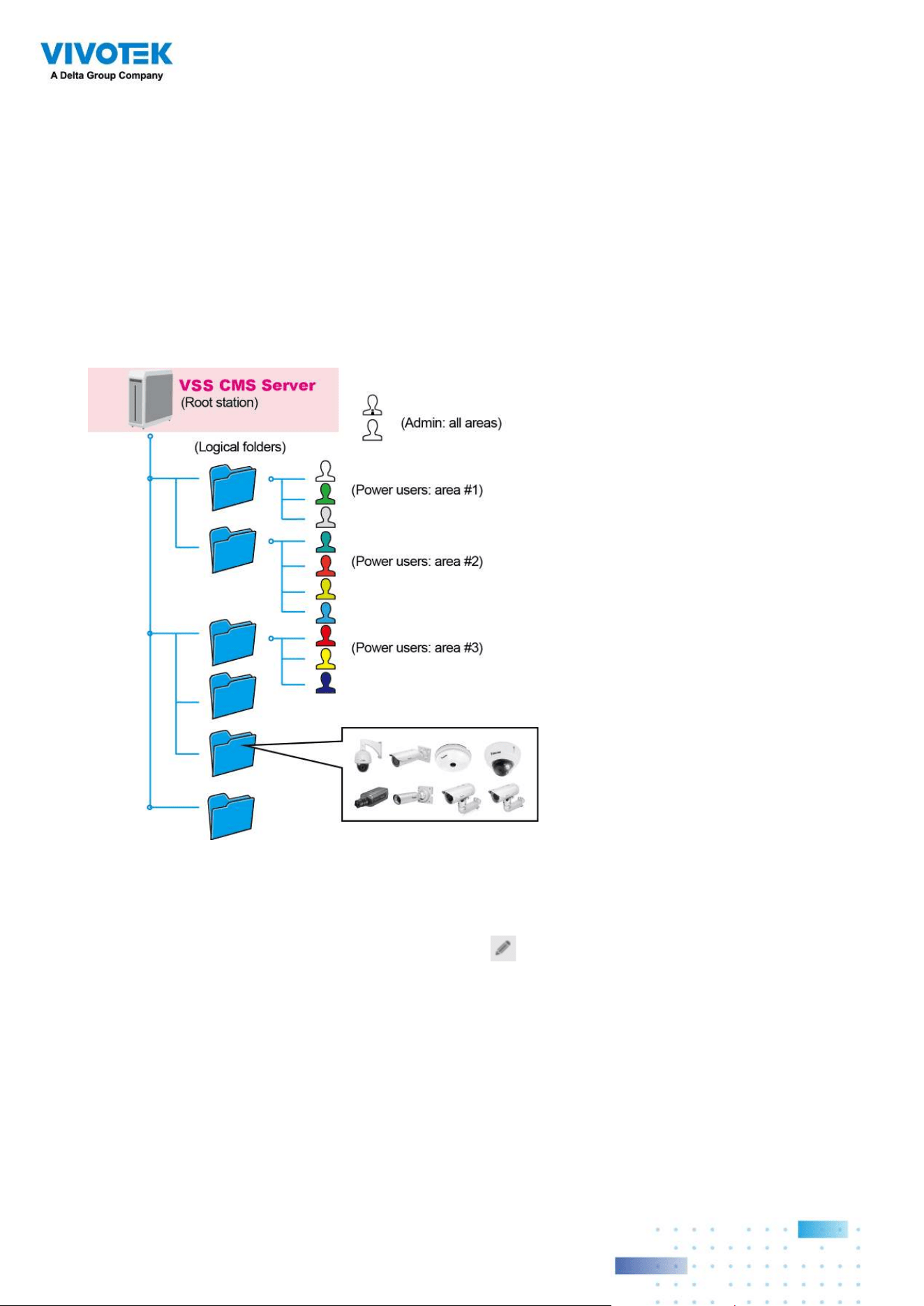
164164
4-3. Logical Folders
The Logical Folders allow you to re-define the logical relationships between the real-
world deployment and the physical devices (cameras). For example, according to your
deployments, you can designate several cameras to be listed under a logical sub-directory
named as "Building A," and the other cameras into "Building B." In this way, you can re-
arrange your cameras and devices on a tree view that is geographically more accurate.
1. On the Settings > Cameras page, click the Edit button.
2. Click on the Add a folder button.
3. Enter a name for the folder, e.g., 1st floor, 2nd floor,... according to your needs as shown
below.
4. Repeat the process to create more folders.
5. Make sure you enlisted all cameras in your deployment. You can start moving cameras
to specific folders. Click on the Move Selected Items button.
To create logical folders,
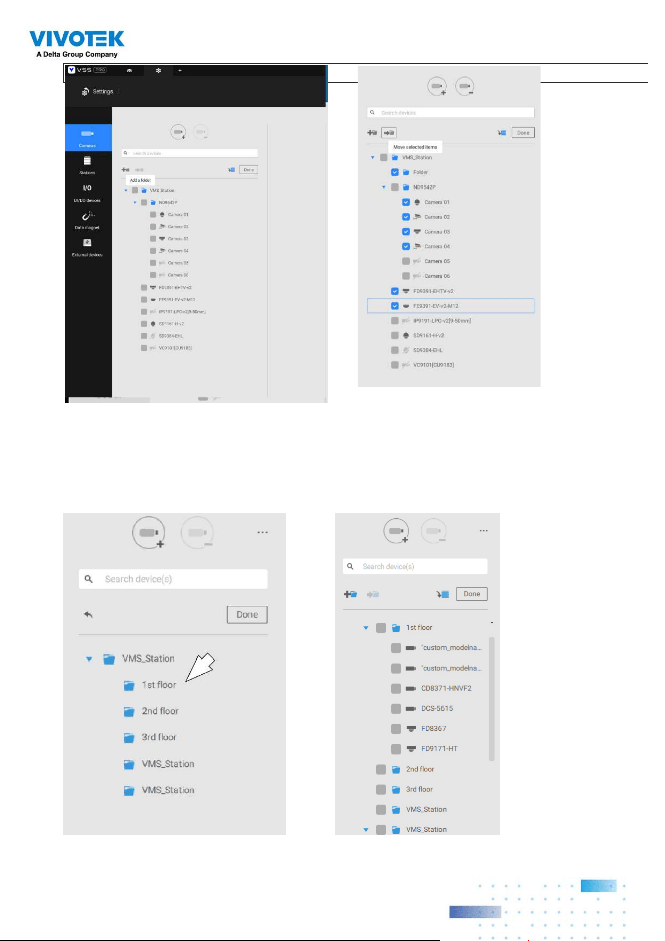
165165
6. Select a logical folder to move the devices to. The selected devices will be listed under
the logical folder you selected. Repeat the process to move cameras to each logical
folder.
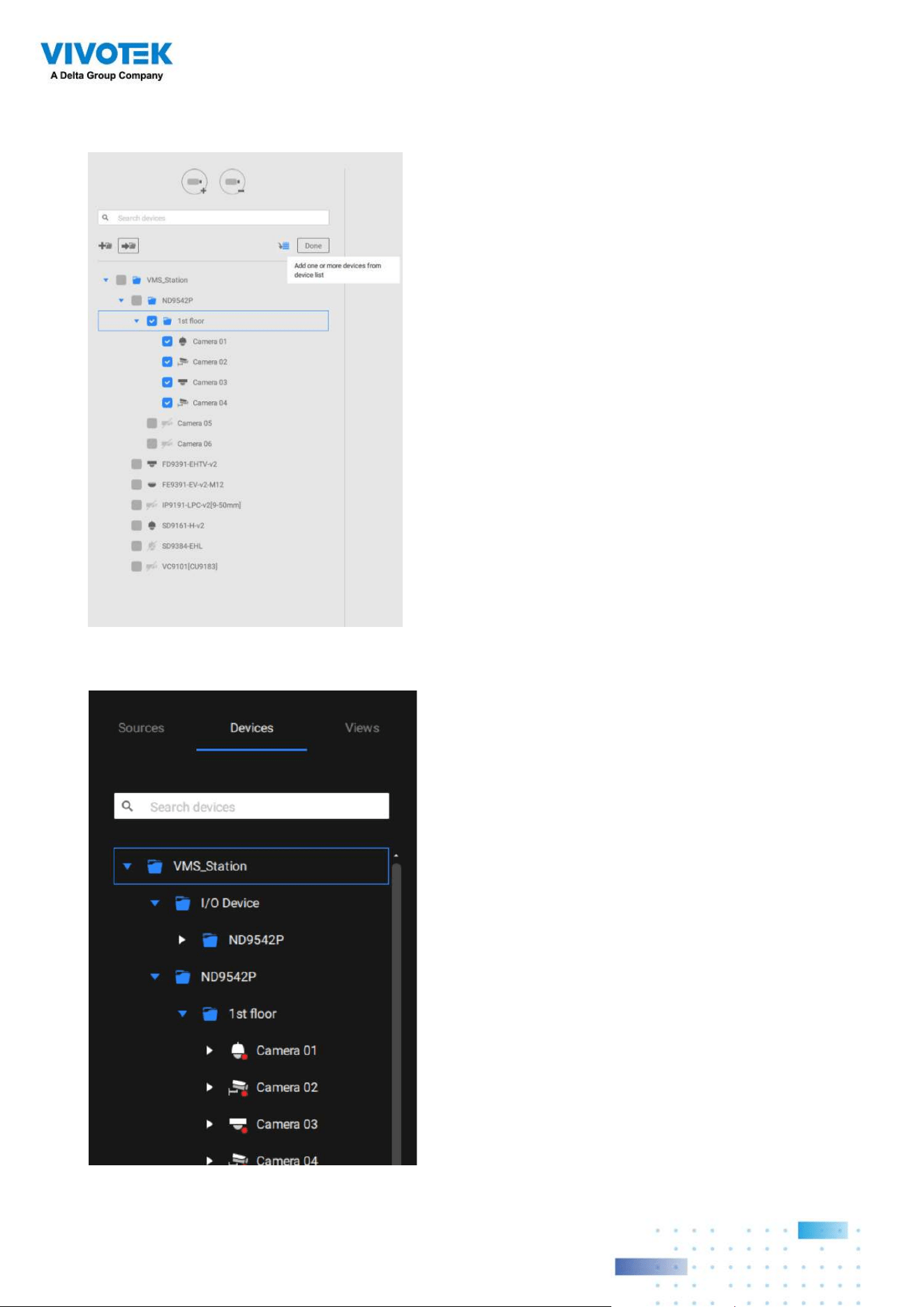
166166
You can also use the add device button to select devices from the list and move them to
a specific folder.
Return to live view, and you can see the configuration change takes effect.
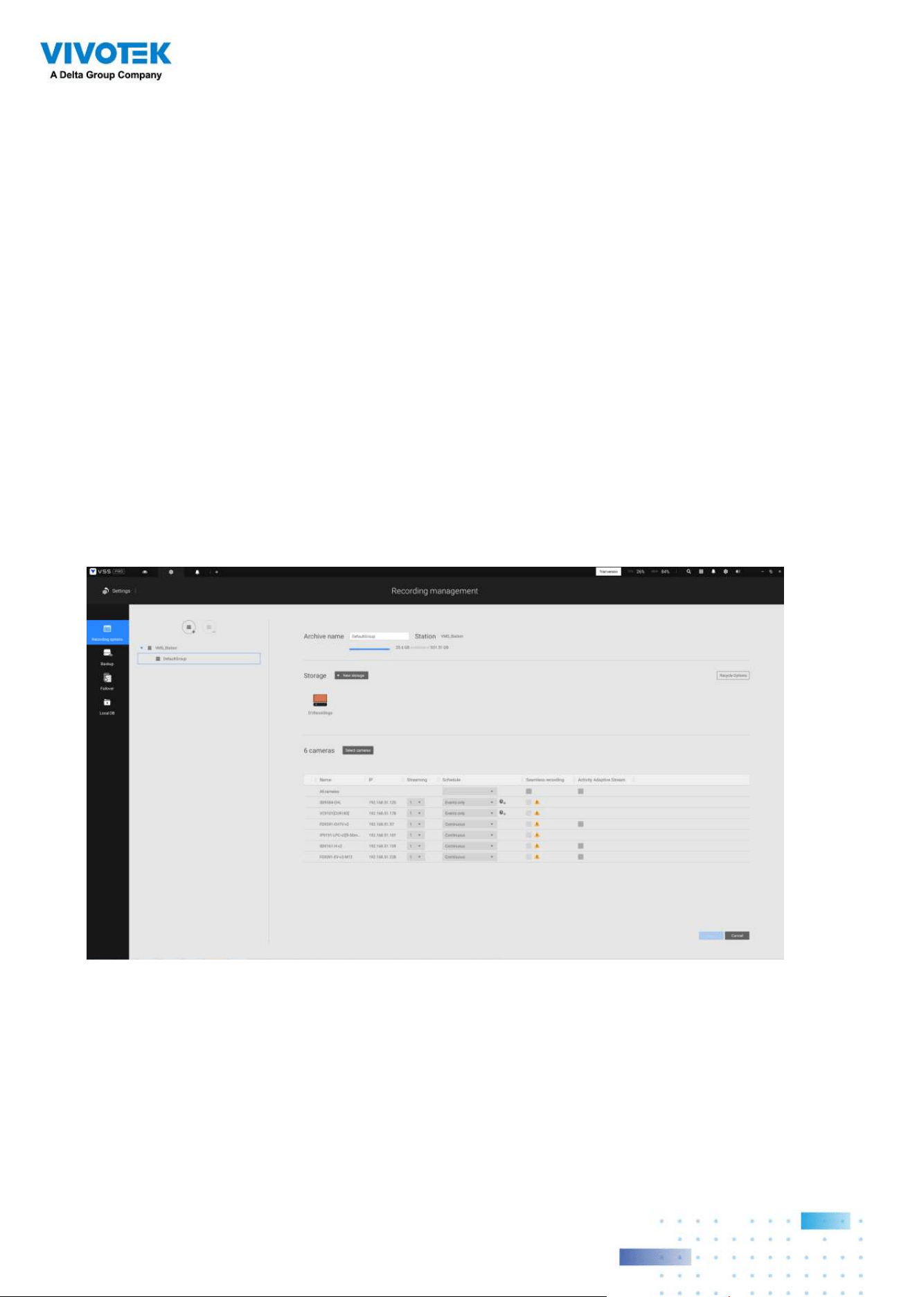
167167
4-4. Settings > Recording >
Recording Options
Click Settings > Recording options. The Recording options window will prompt.
You can configure recording schedules or select the storage options, including the
configuration of an external NAS storage. You can designaate a recording folder of your
choice.
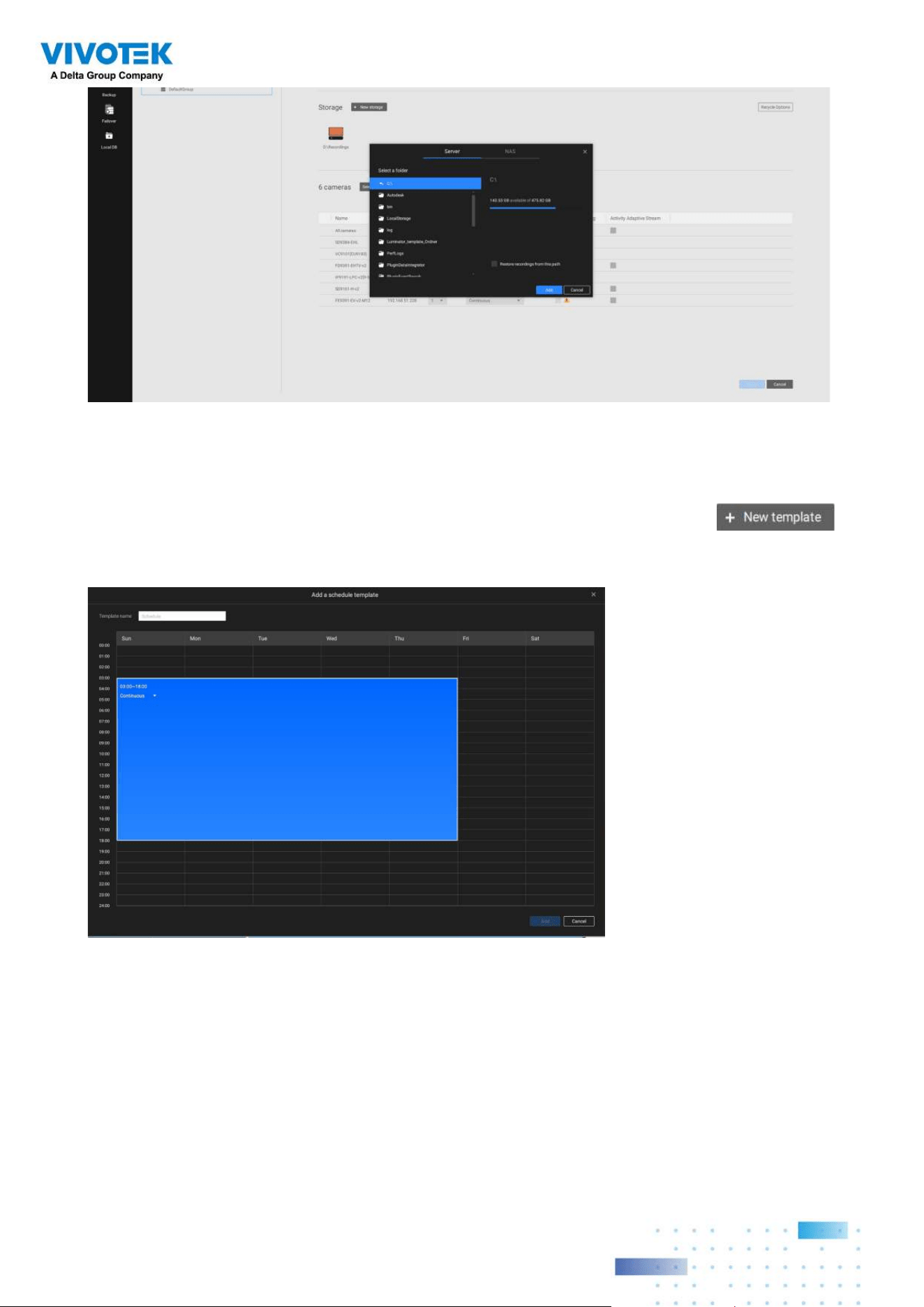
168168
Click and hold down on the time cells, and drag the mouse to include the time span of your
preferrence. The minimum selectable unit is half an hour. You can select multiple time
spans on the template. Enter a name for the template, and click Add to save your template.
The same configuraion window apply to both the Schedule template and the customize
schedule windows.
Make sure a Schedule mode is selected when you leave this configuration step.
Click on any of the options on the Schedule panel for a recording option: Continuous
recordings, Events only, None, or Customize.
You can manually create a recording template using the New template
button.
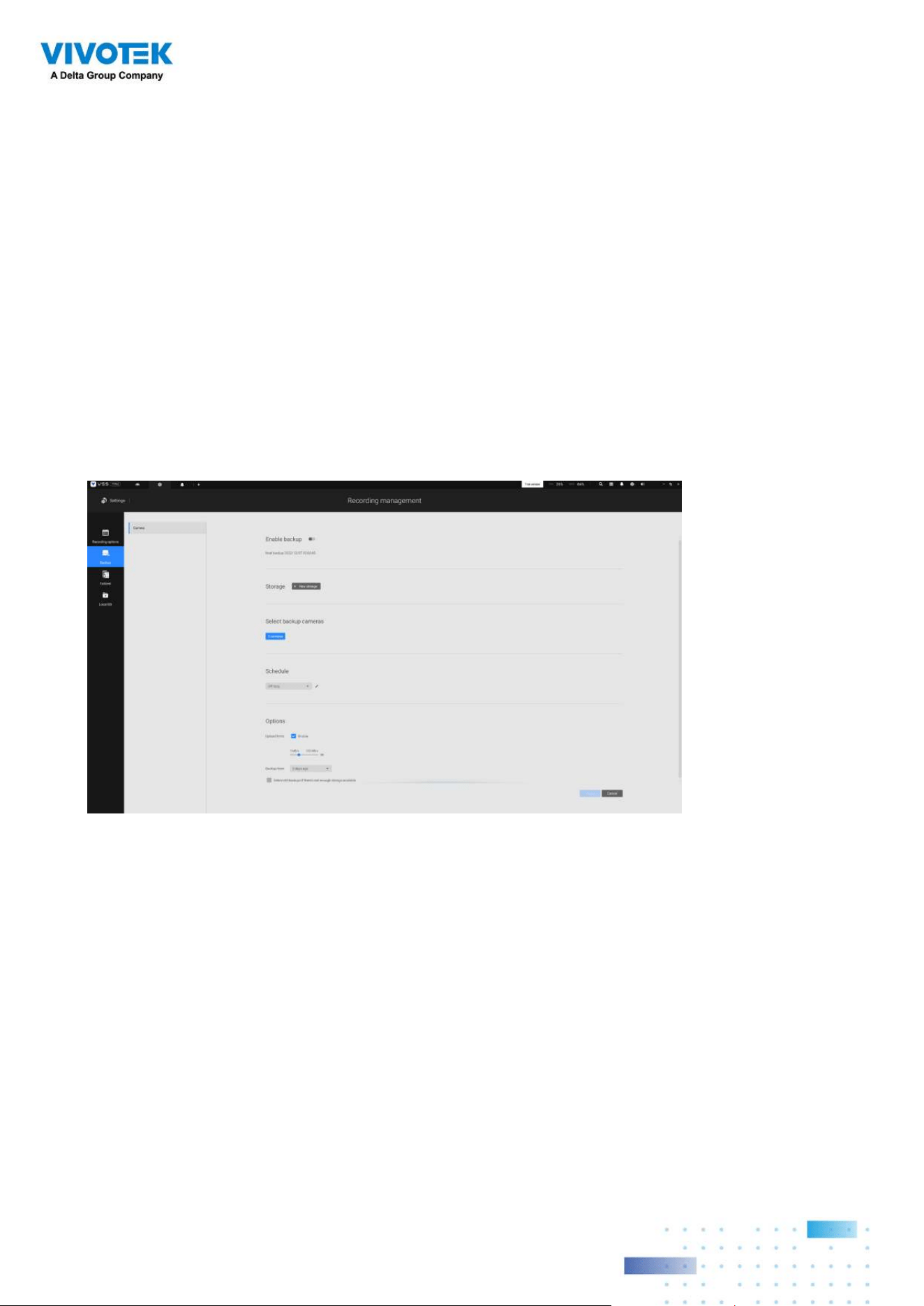
169169
4-5. Settings > Recording >
Backup
The Backup function allows you to regularly back up the video recordings of one or multiple
cameras to local hard disks or a Network Attached Storage device. Currently, the VSS
server does not support backup to external storage devices such as a storage devices
connected via Fibre Channel. VSS supports backup to an external storage attached
through a USB 3.0 connection.
Note that the alarms associated with individual cameras will not be backed up.
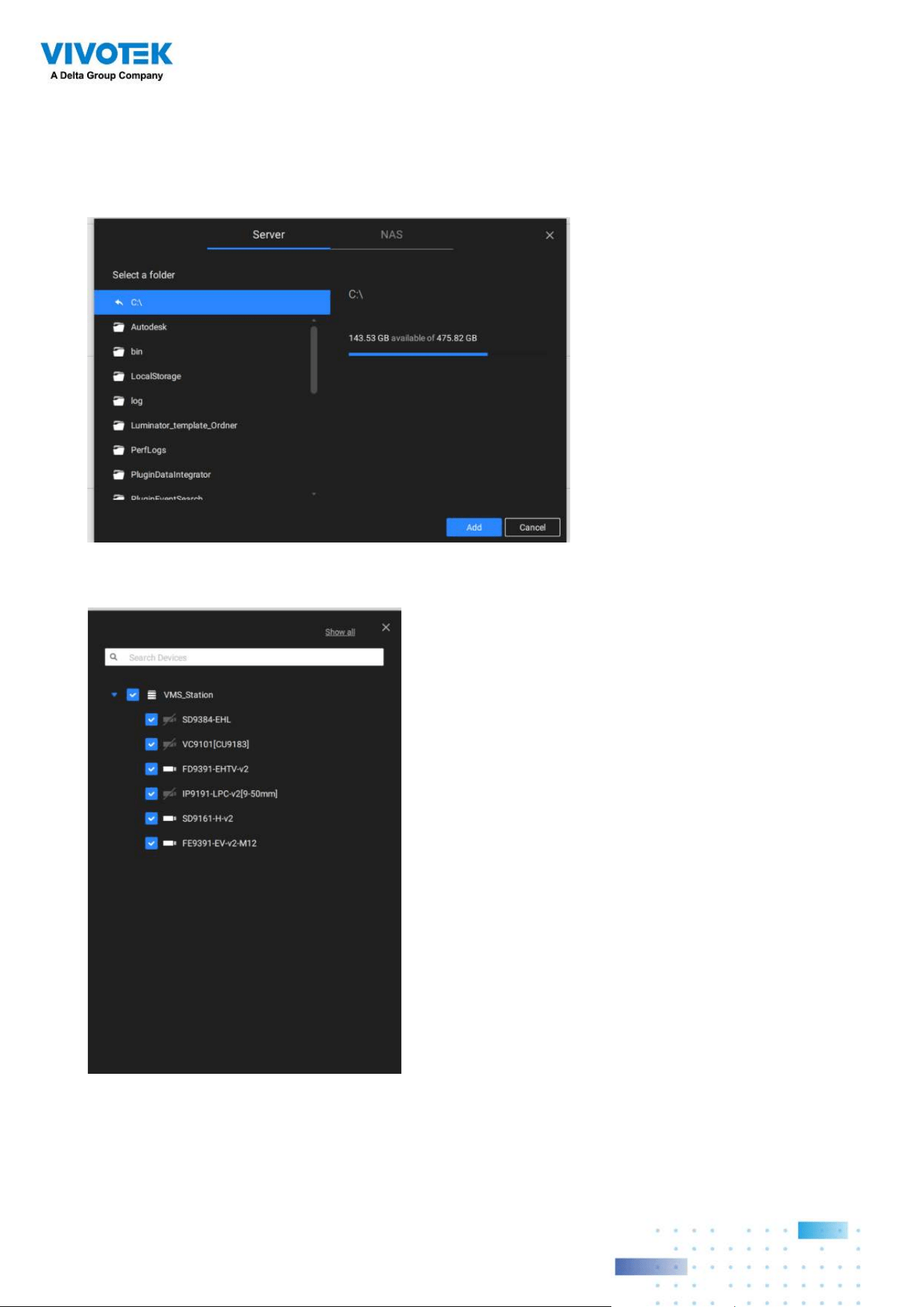
170170
To enable a backup schedule,
1. Enable the backup by selecting the "Enable backup" slide switch.
2. Click to add New storage. A configuration window will prompt showing all accessible
storage. Click the NAS tab to enable access to a network share.
3. Select the cameras whose videos will be backed up.
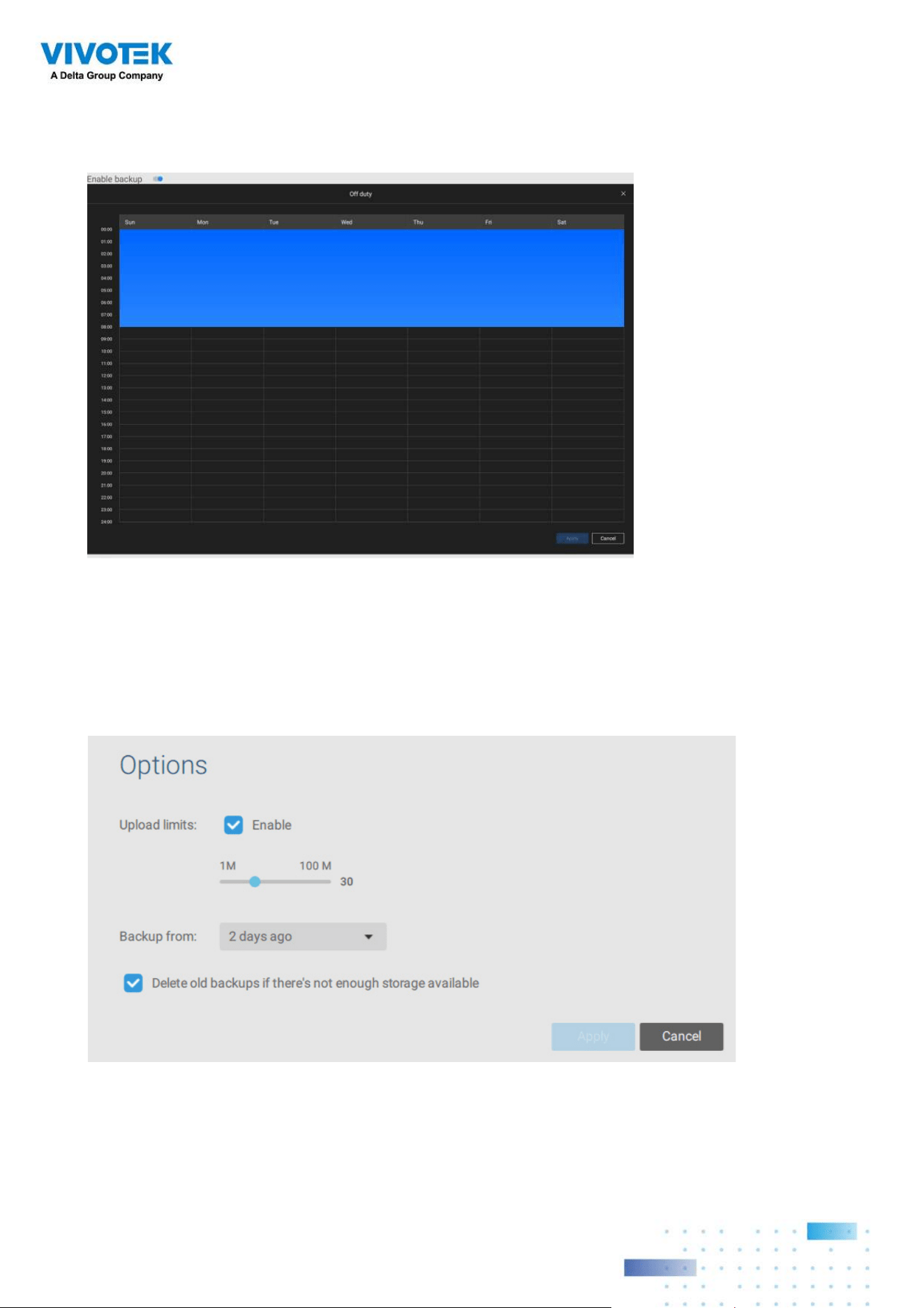
171171
4. Select or congure a new schedule template for the backup process to take place. You
can select a time when the network load is low, such as the off-ofce hours, to avoid
network congestions.
5. On the Options pane, you can congure an upper bandwidth threshold (in Megabytes)
for the backup operation (for all selected cameras/channels).
You can select the extension of time, such as starting from how many days ago, of
your backup task. You can select to remove old backups when you run short of storage
volume.
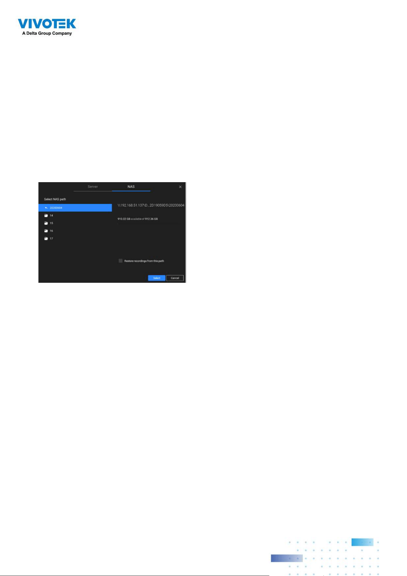
172172
Storage
By default, VSS will check if there is a D: drive. If not, system drive C: will still be defined
as the first storage option. Other disk drives in the system and the default storage volume
(configured in the initial setup) will be listed.
You can add a NAS storage's shared volumes as the additional storage option. Enter the
necessary information for access to a network share. Enter and select a NAS path. The
share will then be available for video recording.
Select storage volumes each by a single click.
Click Ready to use to continue.
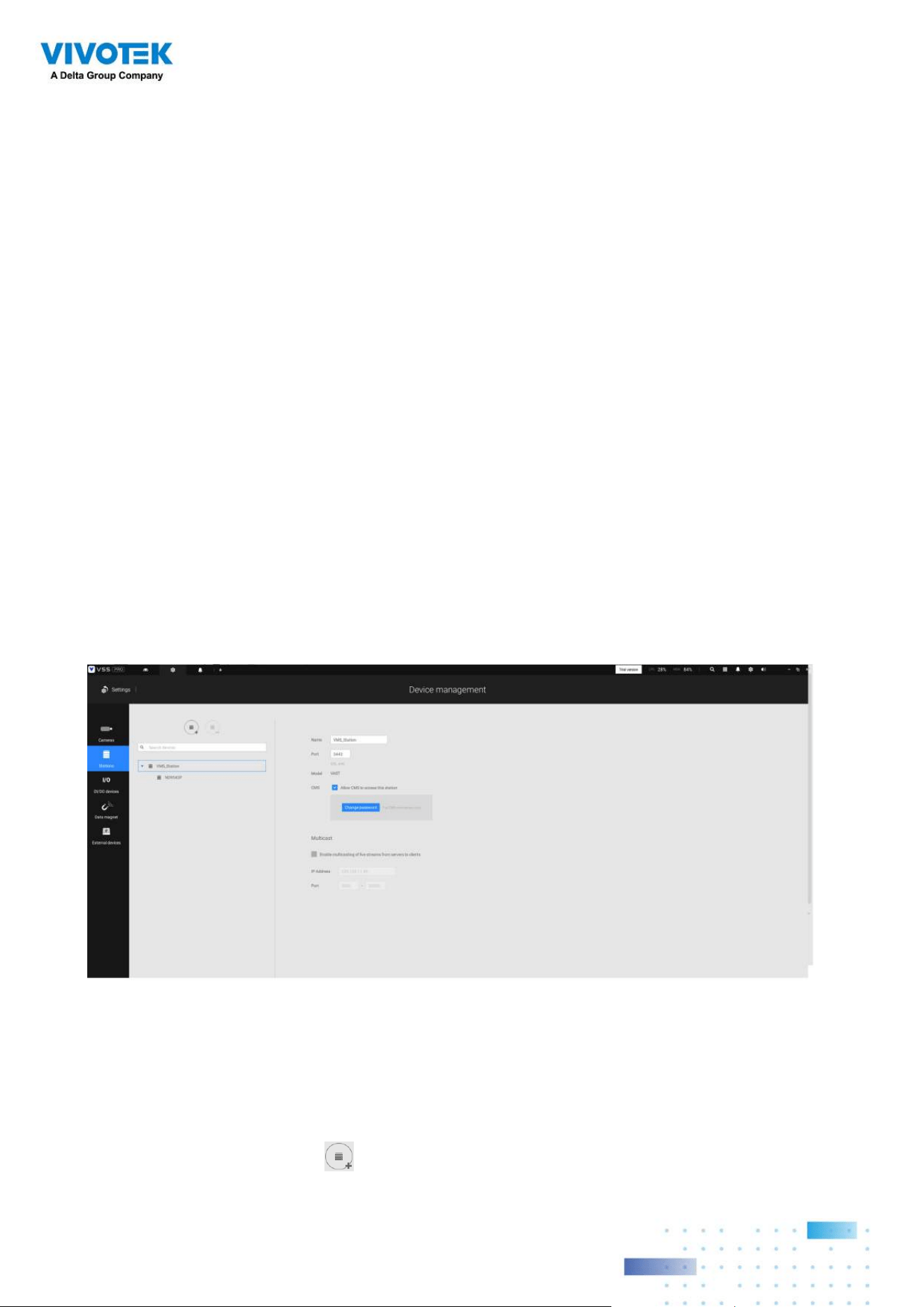
173173
4-6. Settings > Device >
Stations
The VSS allows a deployment consisting of multiple VSS instances at different locations.
A VSS server can be selected as the CMS (Central Management Server) to manage sub-
stations in a hierarchical structure.
Each individual VSS station manages its own surveillance deployments. To build a
hierarchy, proceed with the following:
1. Open the VSS client on a substation.
2. Enter Settings > Stations.
3. Enter a TCP
Port number if your network configuration requires a different port.
4. Select Allow CMS to access this station.
5. Click Change password. This password will be used to authenticate the connection
between a CMS VSS server and substations.
6. Click the Apply button.
7. Open the VSS client on the server chosen as the CMS.
8. Click the Add substations
button.
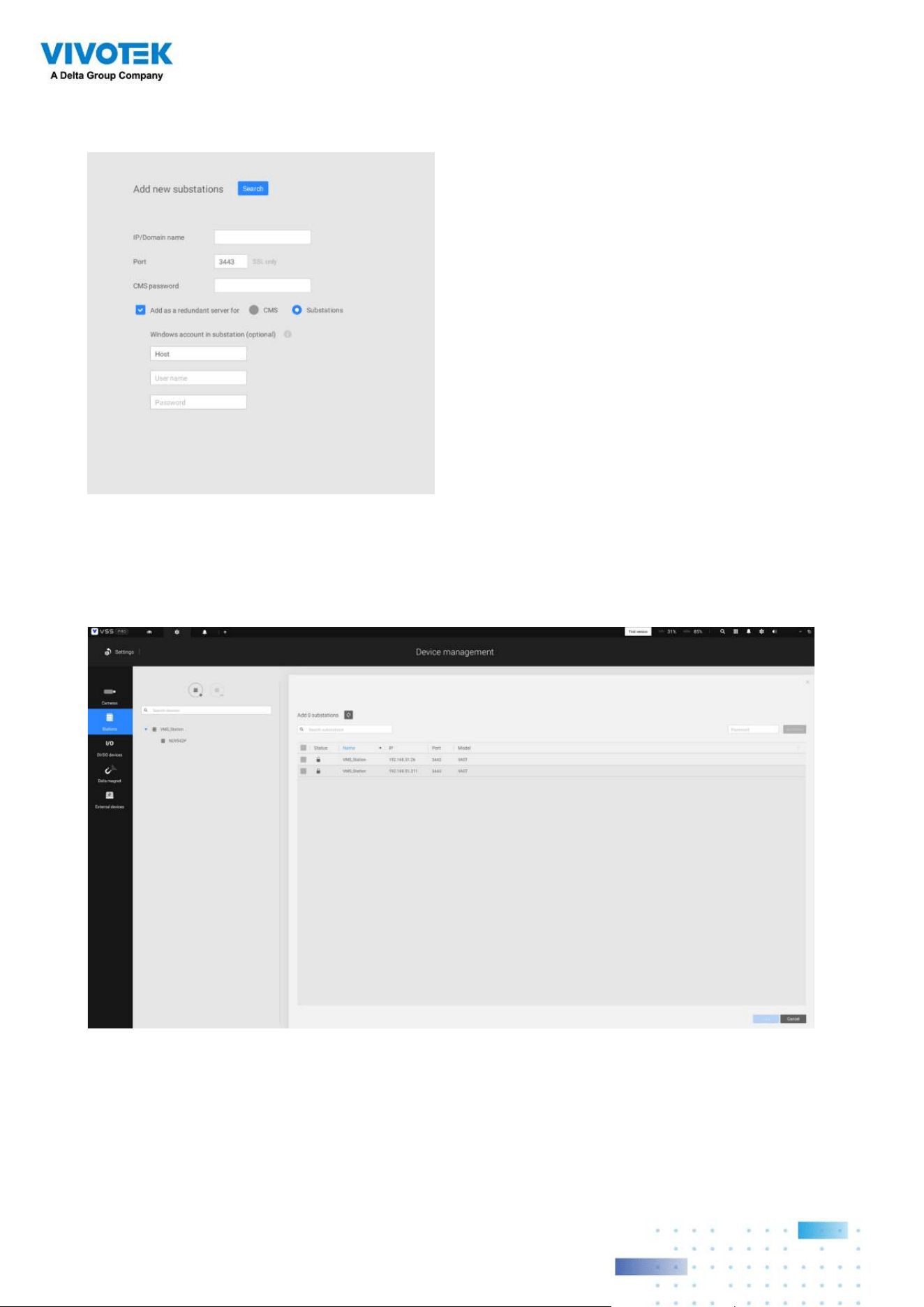
174174
9. You can click the Search button if the substation is reacheable in a local network, or
manually enter the IP address and password for making the connection.
10. Enter the password you configured for the Stations configuration, and then click the
Authorize button.
Click the Apply button for the configuration to take effect.
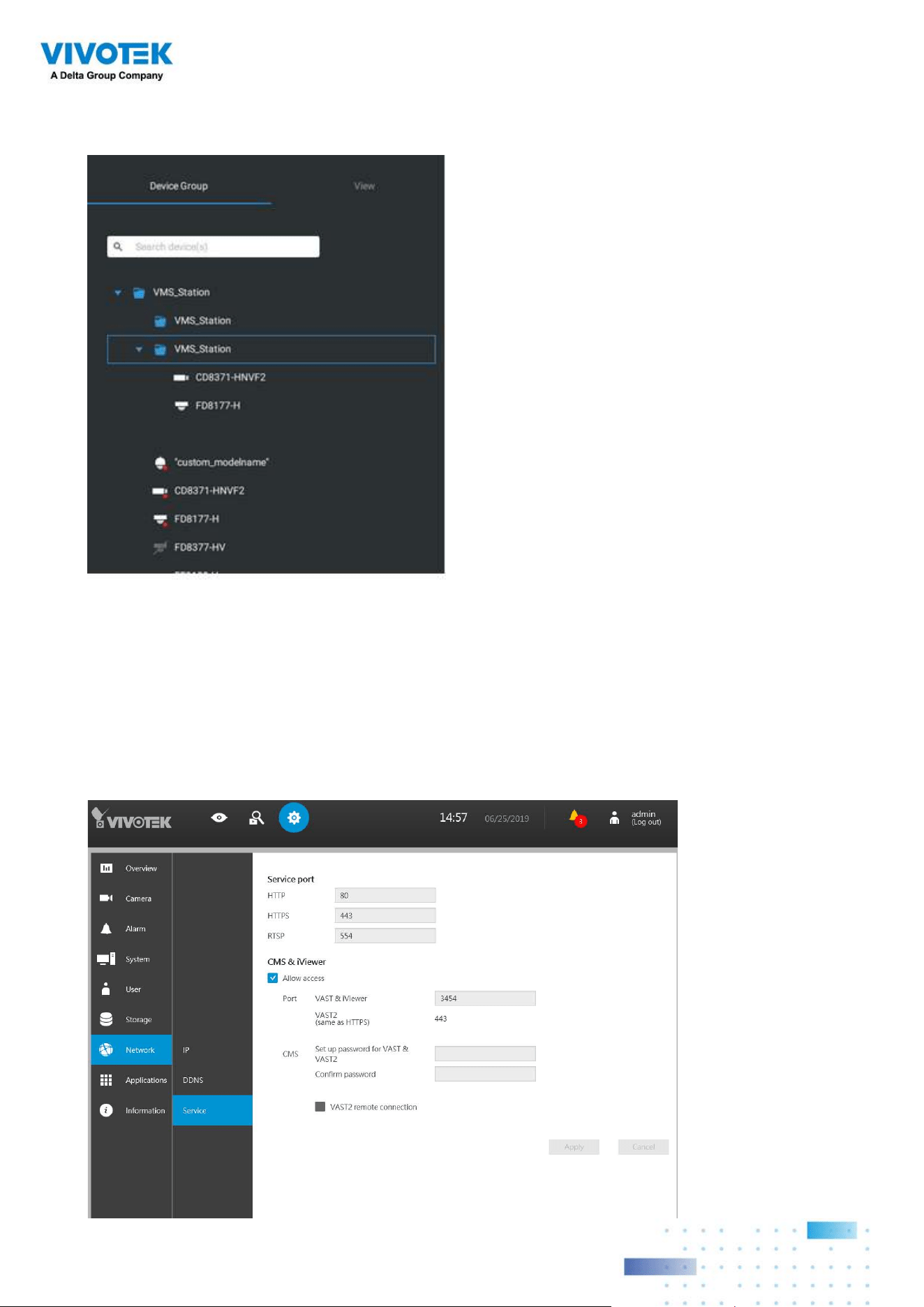
175175
The substations and its subordinate devices should be immediately listed under the CMS
station. You can create separate views to place the substations' cameras.
When you want to enlist an NVR into your conguration, please remember to enable the
access from VSS server in the NVR's Service page.
The connection between VSS and NVR is made via encrypted https.
If the connection port is changed to a non-SSL port, the access from VSS to NVR will
fail. For adding the ND series NVR, use port 443.
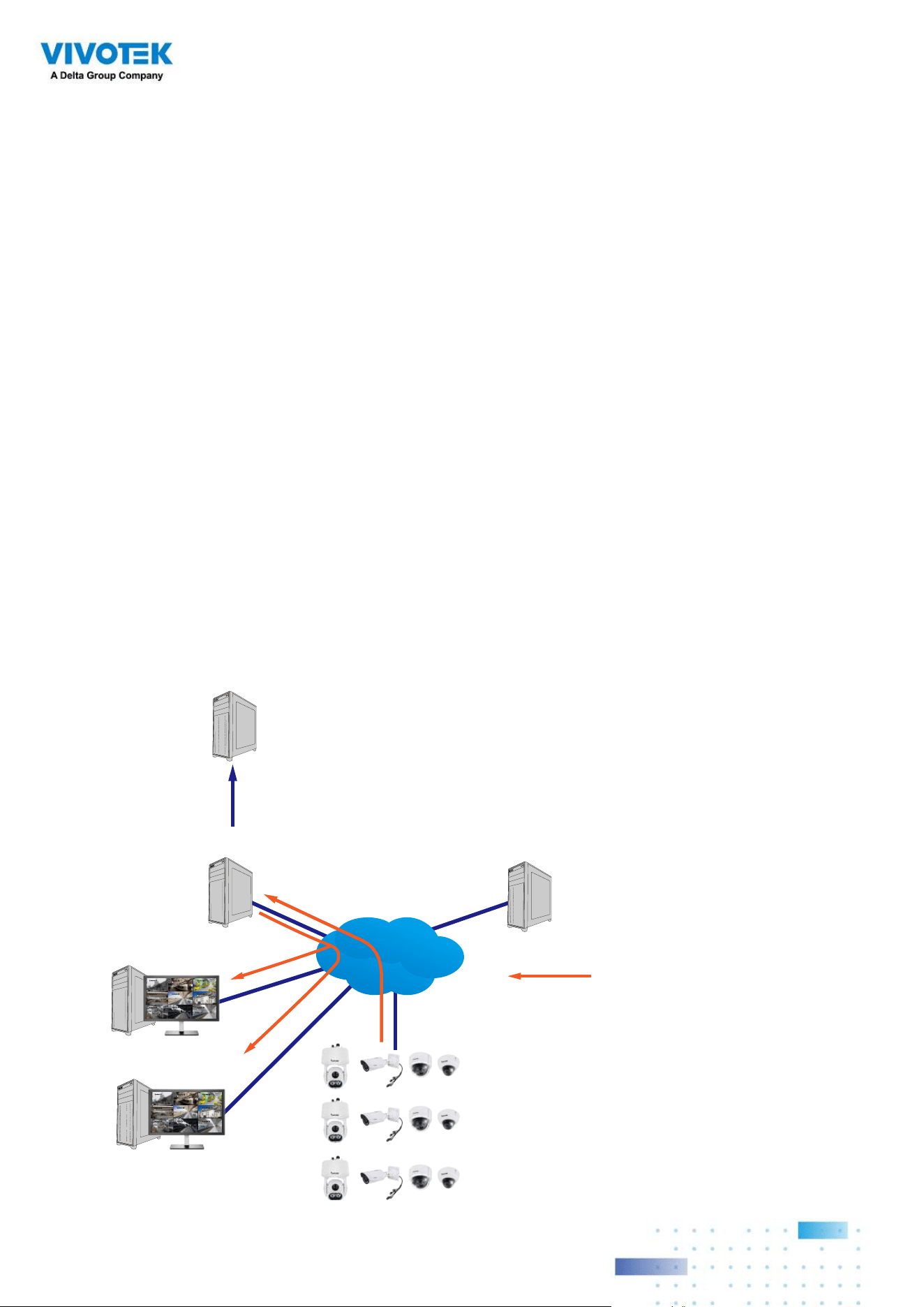
176176
Multicasting
The VSS supports multicasting of live streams from server to clients. If multiple VSS
clients demand live videos from the same camera, multicasting cna help save considerable
system resources.
Multicasting should be enabled on a VSS server and also on individual cameras.
There are prerequisites:
Multicasting is not supported under the following conditions:
* A CMS local client can only access the live stream from the cameras managed by the
CMS server using unicast connections.
* If the need arises for access to cameras managed by VSS sub-stations, the
multicasting configuration should take place on the sub-stations instead of on the
CMS server.
CMS VSS
LAN
Video streaming
Camera 01
Camera 02
Camera 03
Camera 04
Camera 06
Camera 05
Camera 07
Camera 08
Camera 09
VSS Client
Camera 01
Camera 02
Camera 03
Camera 04
Camera 06
Camera 05
Camera 07
Camera 08
Camera 09
VSS Client
VSS Substation
VSS Substation
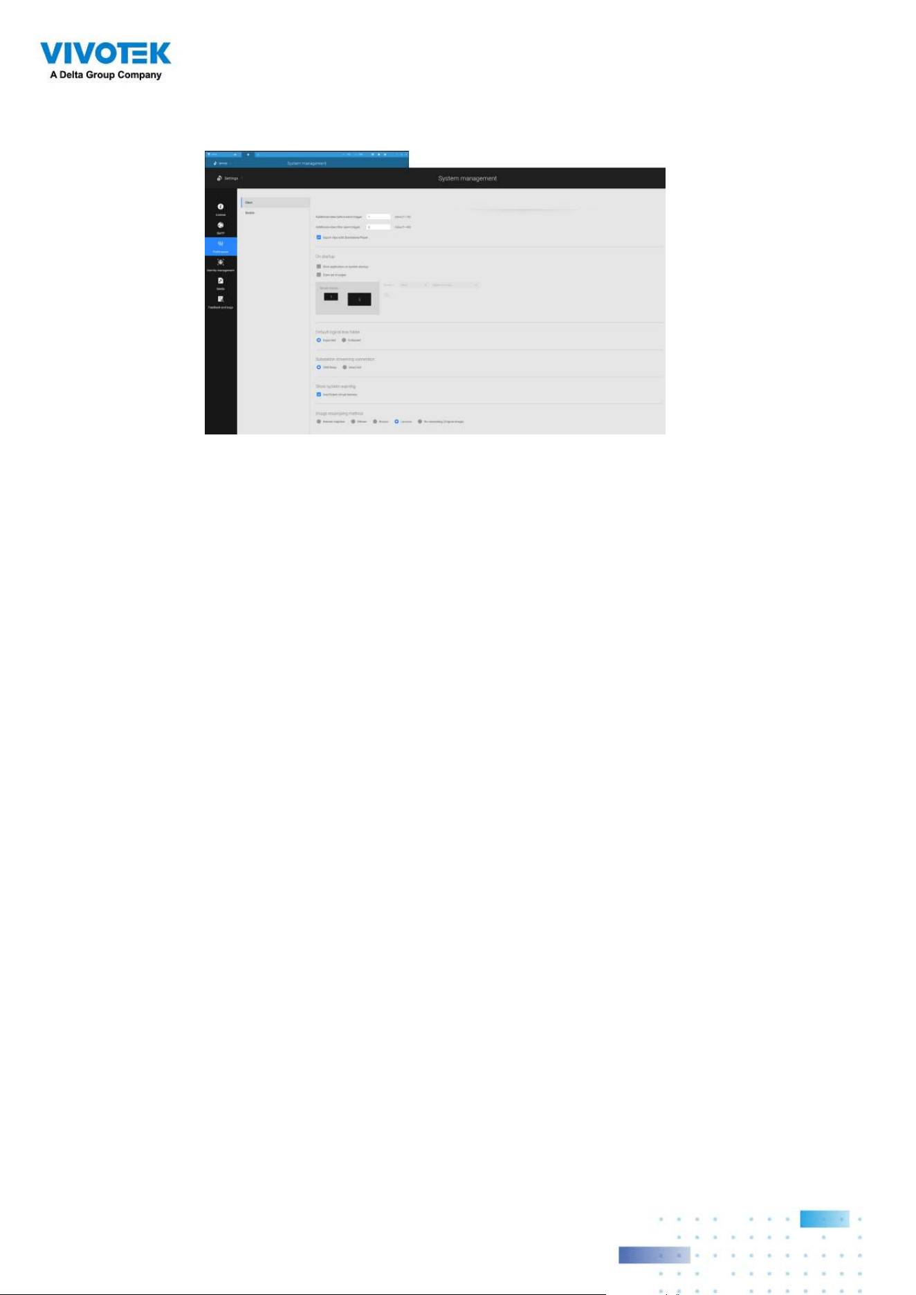
177177
* To enable multicasting, your network infrastructure must support the IP multicasting
standard IGMP (Internet Group Management Protocol). Your server and clients should
be on the the same network segment.
* Multicasting is only possible for live streams, not applicable to the recorded video or
audio.
* Multicast streams are not encrypted, even if the the recording server uses encryption.
* The IPv4 multicast address range is: 224.0.0.0 to 239.255.255.255.
* A layer 2 network switch that supports IGMP is required in the configuration.
* If the streaming connection for a sub-station is configured as
CMS Relay, you should
configure the multicasting settings on the CMS server.
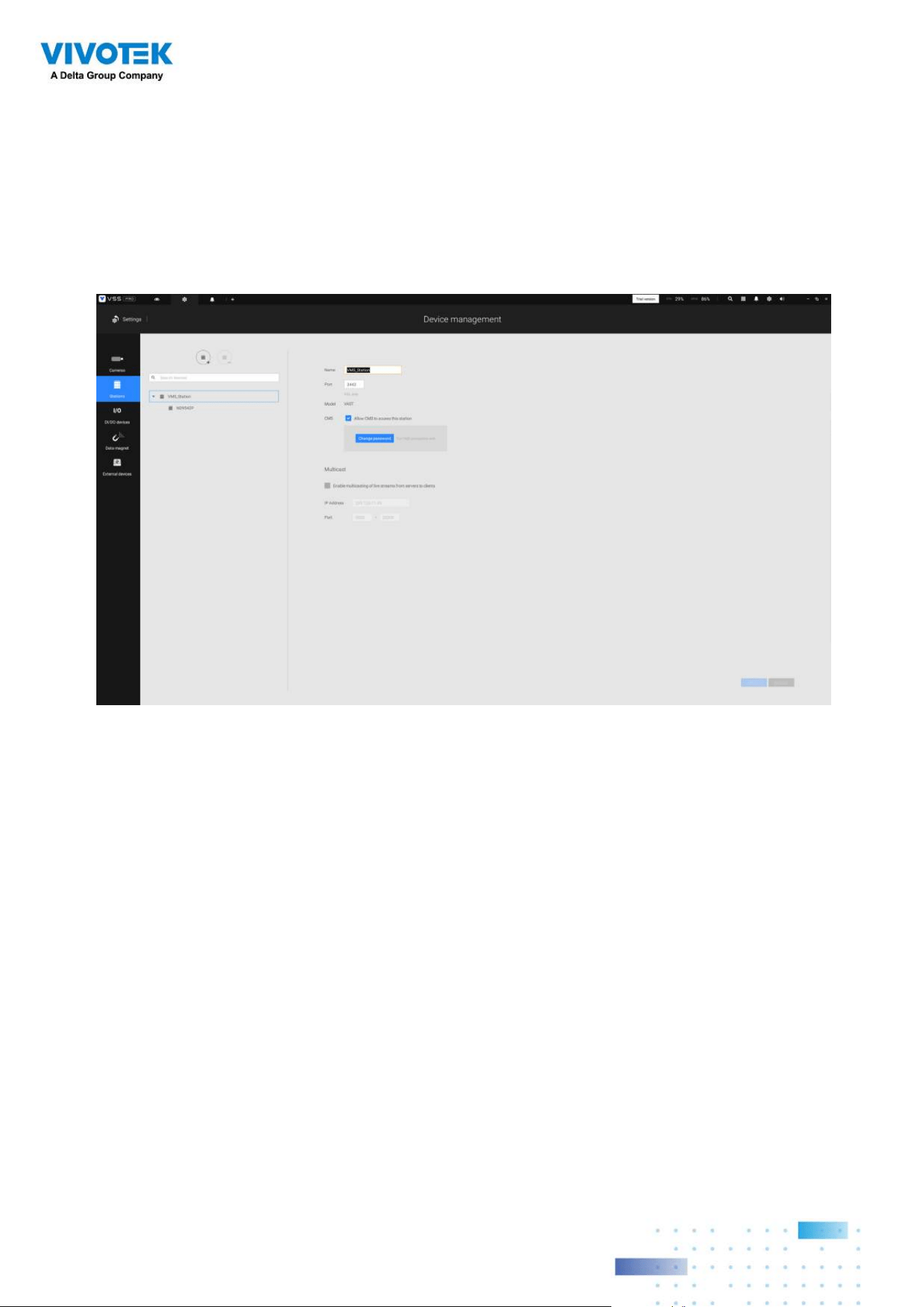
178178
To enable Multicasting on a VSS server:
1. Enter Settings > Device > Stations.
2. Single-click to select a server for which you want to enable the Multicasting.
3. Click the checkbox to enable the configuration and enter the multicast address.
4. Click the Apply button.
Starting the Multicasting service will restart the VSS server.
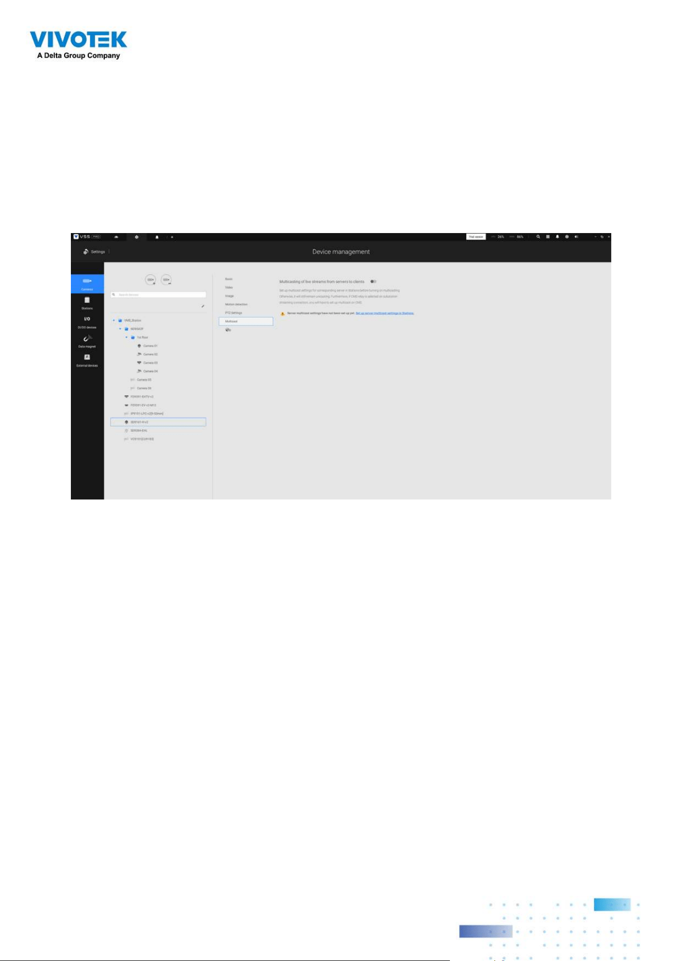
179179
To enable Multicasting on a camera:
1. Enter Settings > Device > Cameras.
2. Single-click to select a camera for which you want to enable the Multicasting.
3. Click to select the Multicast tab.
4. Click the Multicasting slide button.
5. Click the Apply button.
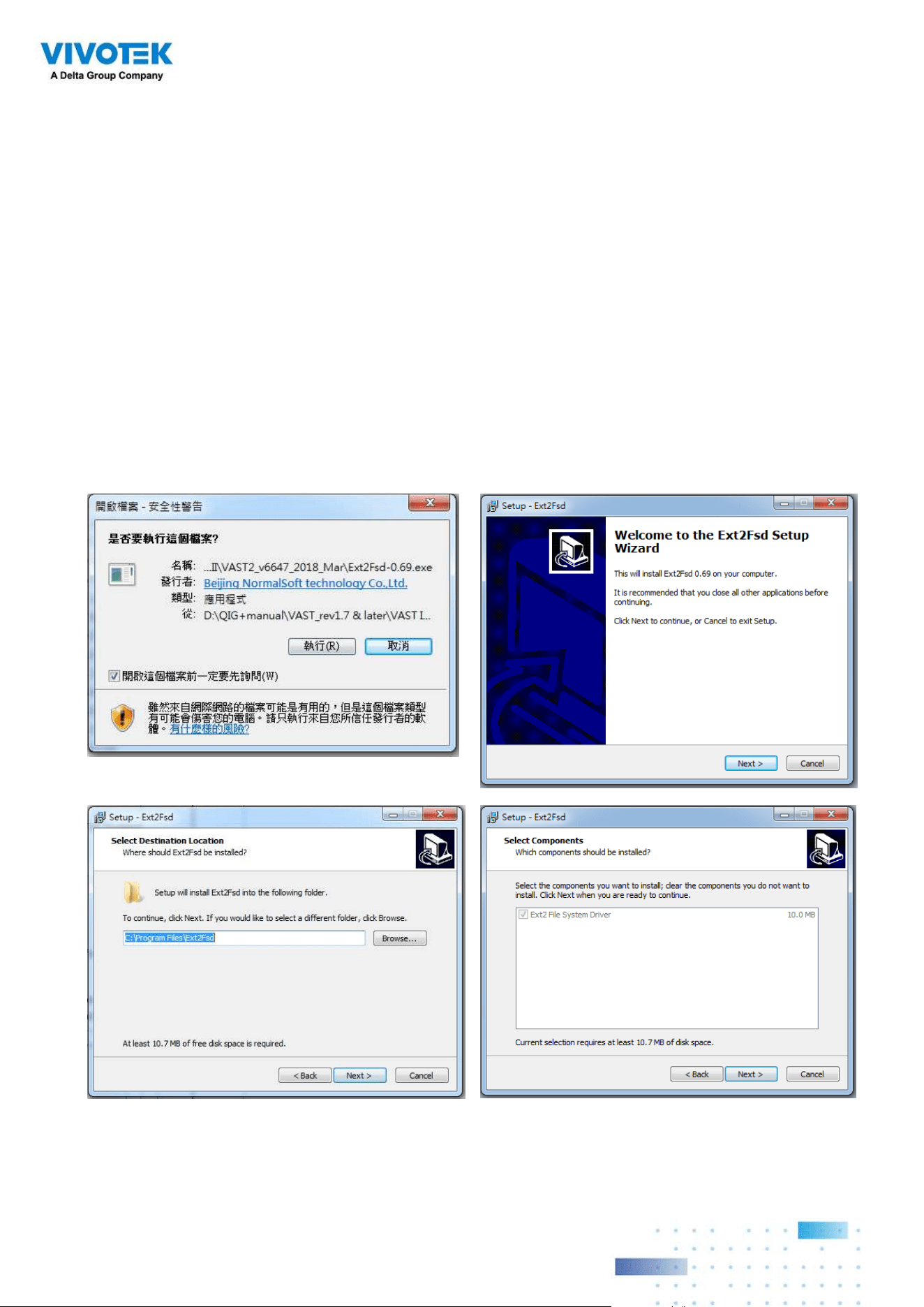
180180
4-7. Settings > Device >
Local DB
Since some of VIVOTEK's NVRs run on Linux, you have to install the Ext2 File System Driver
for Windows to access the recording files from a NVR hard disk.
The file system driver can be found here: https://sourceforge.net/projects/
ext2fsd/?source=typ_redirect
Run and install the Ext2fsd-0.xx.exe. Follow the onscreen instructions to complete the
installation.
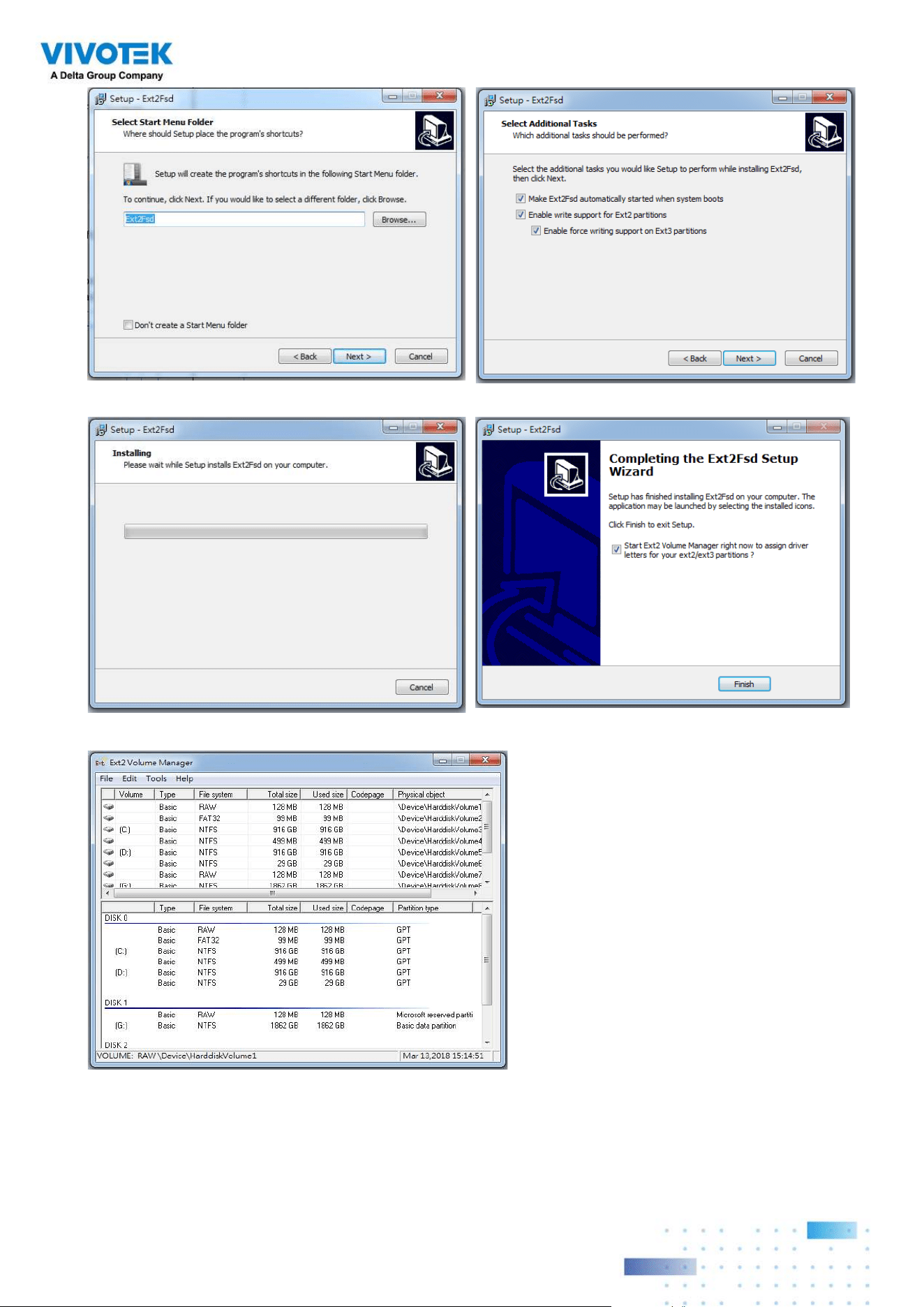
181181
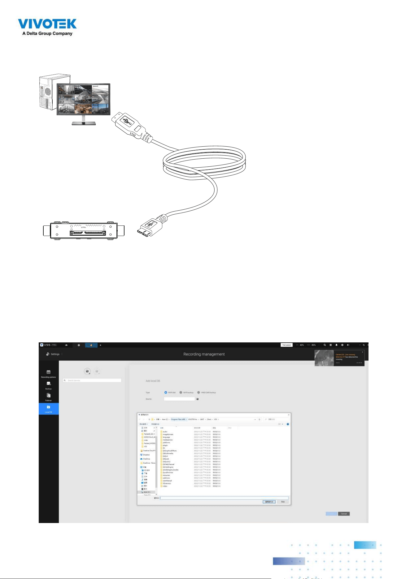
182182
1. Remove the disk tray box from a mobile NVR.
2. Connect the disk tray box to your VSS server using a USB 3.0 type A to Micro B cable.
Camera 01
Camera 02
Camera 03
Camera 04
Camera 06
Camera 05
Camera 07
Camera 08
Camera 09
VSS
USB Micro BMobile NVR
Disk Tray
3. From VSS, enter Settings > Device > Locabl DB.
4. There are 3 import types:
1. NVR disk: the drive tray box removed from a mobile NVR.
2. NVR backup: the recorded videos exported from an NVR using a USB thumb disk or
portable drive.
3. VSS backup: scheduled backup from the local machine. They include: VSS backups
from previous software releases, and scheduled backups.
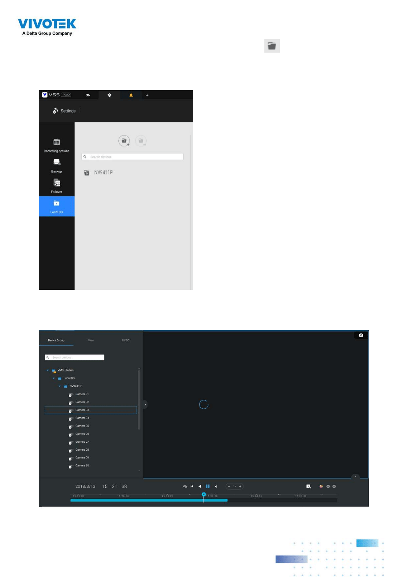
183183
5. Taking a mobile NVR's disk drive as an example, click the Source select button to
locate the disk drive.
6. The NVR will be mounted as a local DB.
7. A Local DB sub-tree will be listed under your server, and you can view the existing
recordings on the NVR's disk drive.

184184
4-8. Settings > System >
SMTP
Configure a mail server via which the system alarms or notifications can be delivered to a
receiver.
Enter the Settings page, select . Click on the Add SMTP button.
Enter your mail server's domain name or IP address. Enter credentials for access to the
mail service.
If SSL encrypted transmission is preferred, select its checkbox.
Click Add to complete the configuration.
4-9. Settings > IO Box and
Related Configuration
Please refer to page 117 for information.
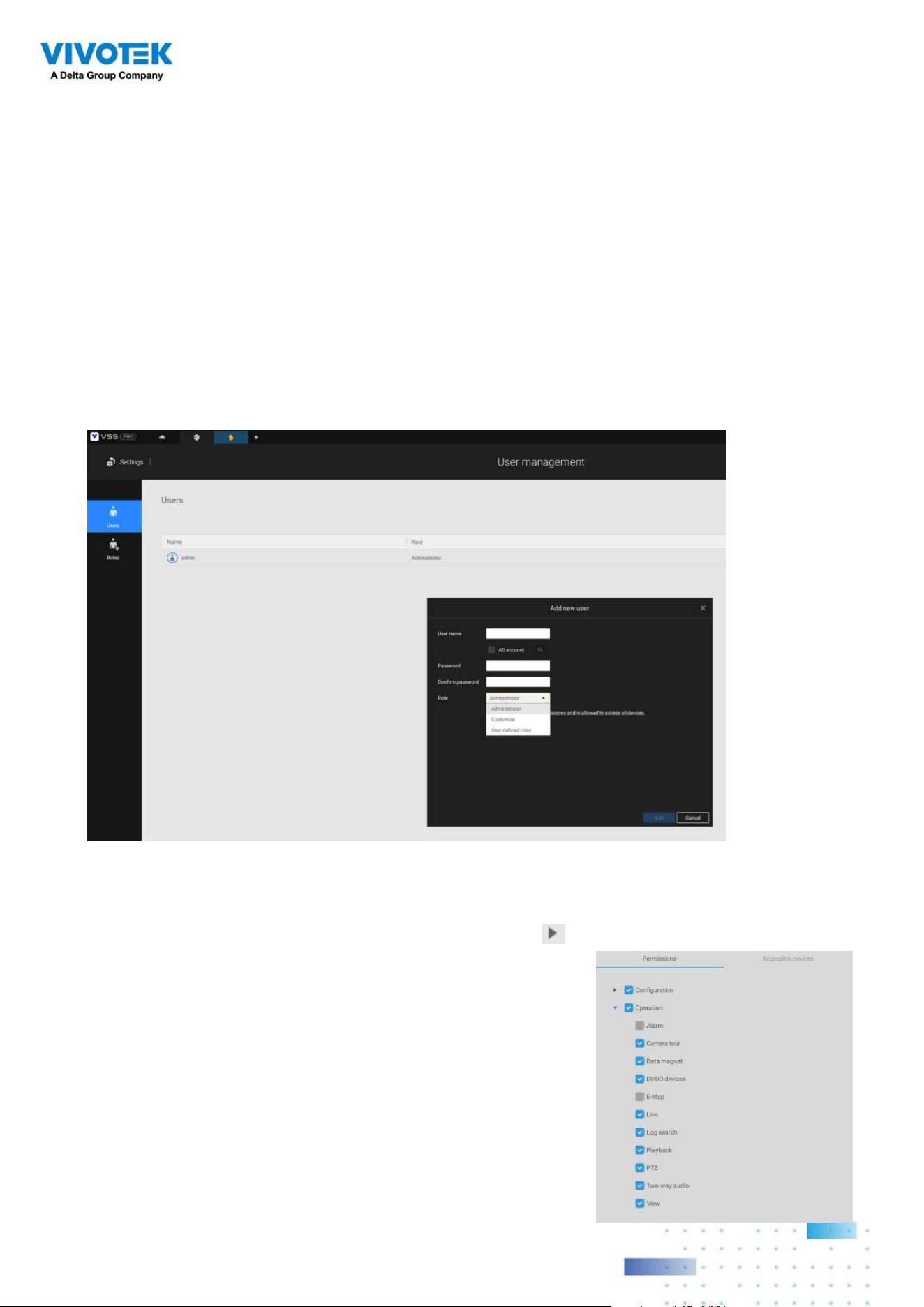
185185
4-10. Settings > User
Management
The User Add & Delete page allows you to create users with the permissions for different
operational capabilities.
To specify the authorized privileges, select Customize in the Role menu, then select the
Permissions and/or the Accessible devices tabbed menus.
Use the Customize option to limit the authorized actions of a user.
In the Permissions tab, click the expand button
to unfold the Operation and
Configuration menus. Select or deselect the checkboxes to
configure the user privileges. For example, you may not want
a user to operate Alarm and E-Map. If so, deselect these
checkboxes.
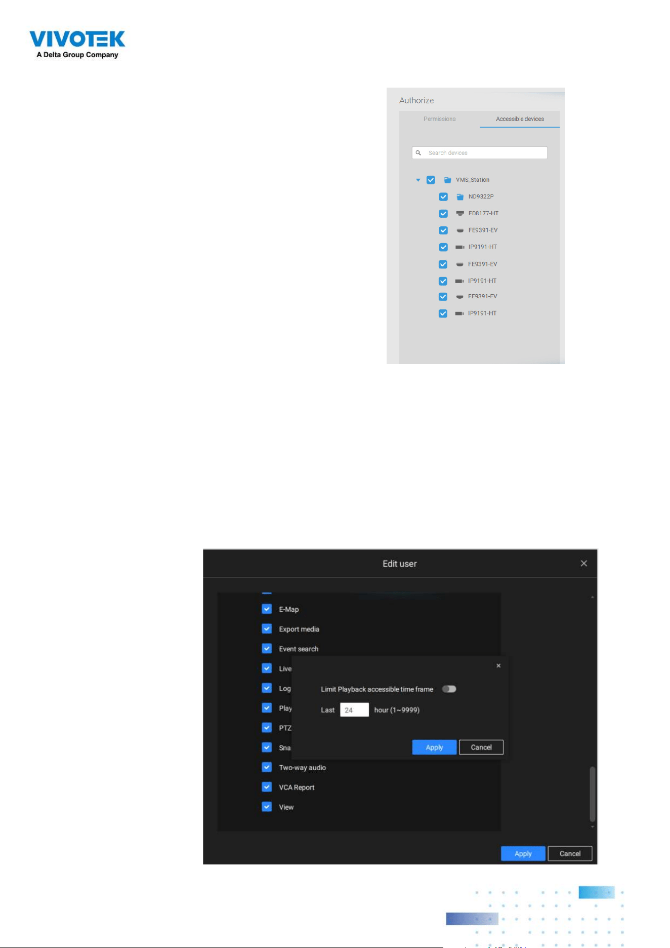
186186
When done with the privilege settings, click Add to create a new user.
The new users will be listed under the Administrator's icon. Repeat the process to create
more users.
In the Accessible devices tab, click to select the cameras that a user can access. Some
users may only need to access specific devices.
Note that you can place a limitation on a user's access right to the recorded videos by
setting a barrier for access to the older recordings. Recordings older than a configurable
period of time will not be accessible.
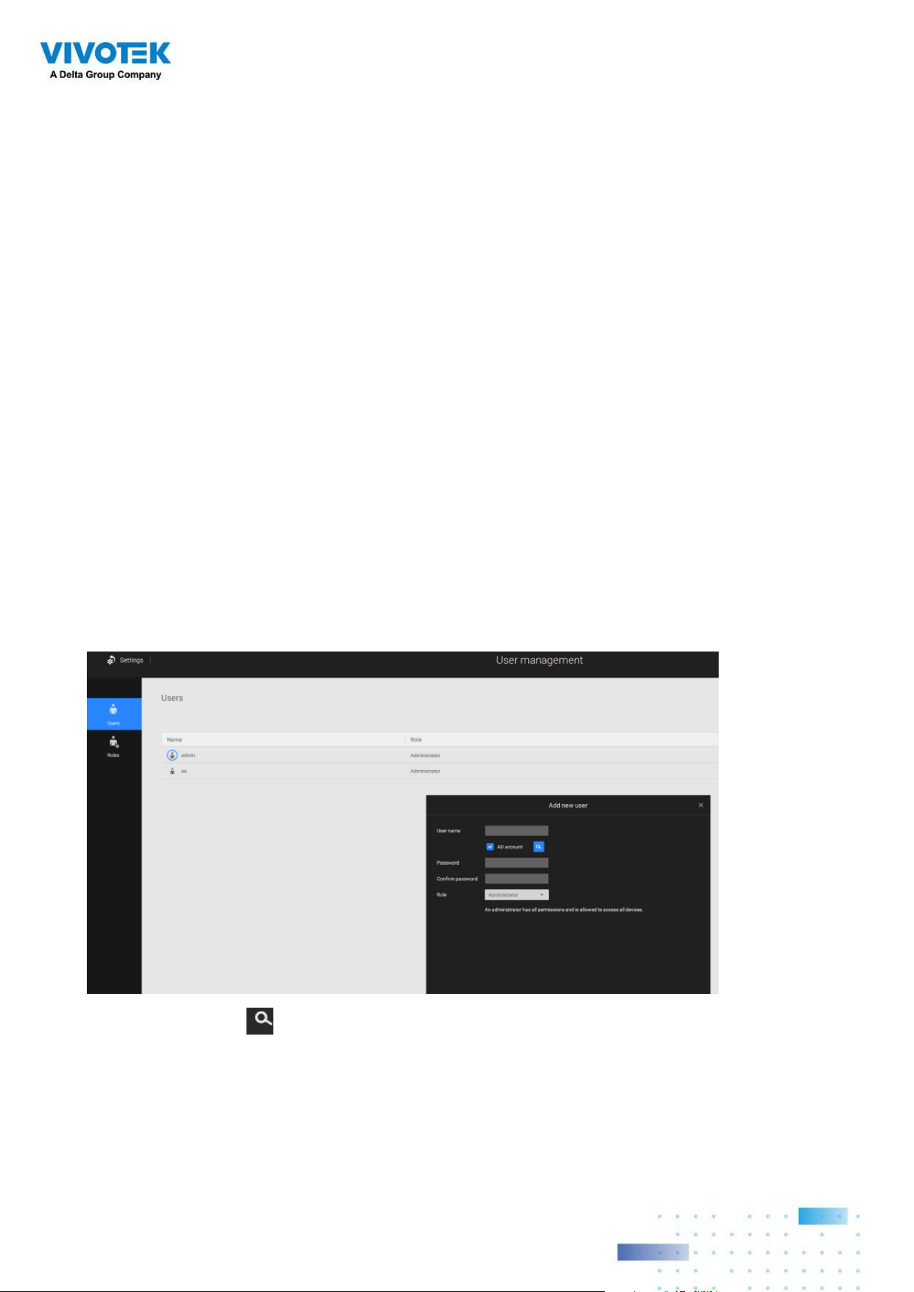
187187
Add a New User Account - Windows AD Account
In an established, enterprise network environment, the support for Windows AD (Active
Directory) infrastructure enables ease of integration using the credentials of existing users.
Using the same AD authentication methodologies, you can configure the clients or users in
an established network to access the VSS server configuration.
Note the following with Windows AD support:
1. If you install VSS server on a Windows XP machine with Postqre SQL server, the login
using a Windows AD account will not work.
2. The VSS server must reside in a domain managed by the AD server.
3. This function does not support the environment that spans across multiple AD domains.
4. A user account hosted by an AD server cannot be modified in VSS.
5. A User Group and its members configured in AD cannot be managed in VSS.
6. You cannot add an account having the same name as one you used to log in VSS.
7. There are 3 types of account for VSS: VIVOTEK account, AD single user, AD group.
8.The userPrincipalName of your Windows AD account can be different from the
sAMAccountName. However, You can only use the sAMAccountName to login VSS.
9. The userPrincipalName field of your Windows AD account should not be empty.
To add an existing AD user,
1. Select the AD account checkbox.
2. Click the Search button.
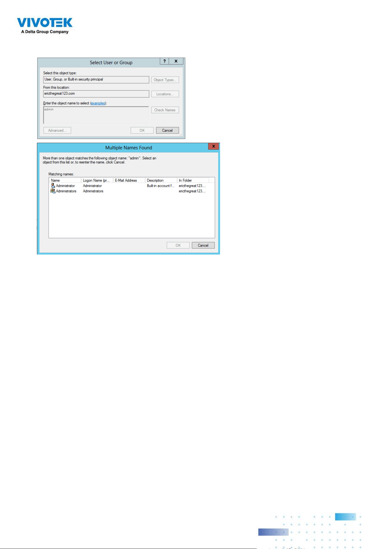
188188
3. Enter a user name or group name to search, e.g., Frank. Click OK when done.
4. Enter the password twice for the AD user.
5. Select the privilege role for the user, congure his/her privilege settings as described
above and then click Add.
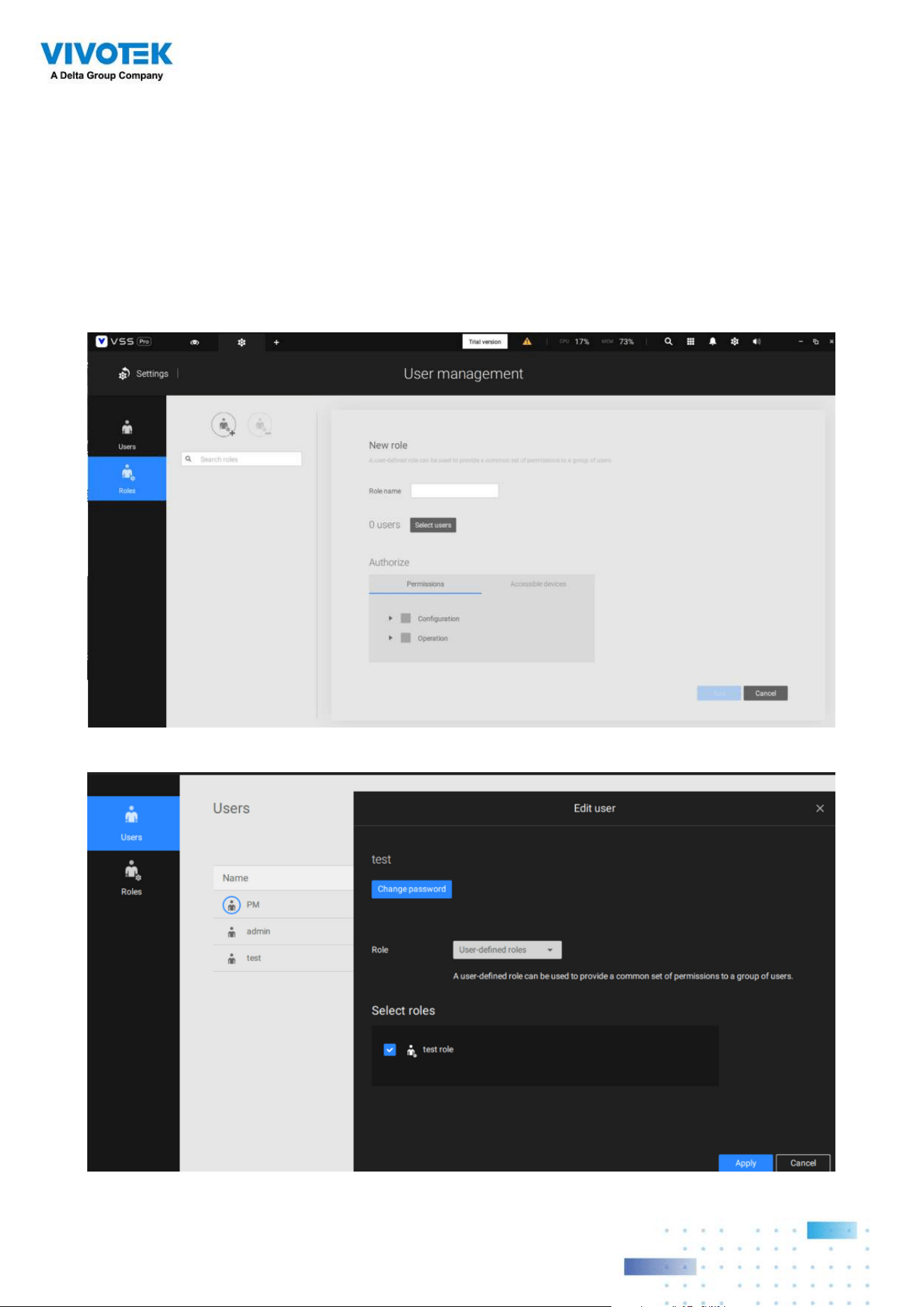
189189
User Roles
A user-defined role allows you to define a common set of permission a for group of users,
reducing the setup time for different groups of users.
You can specify the role name in the rst column. Also, you can select existing users for this new
role. Note that once the users are selected for a new role, it will change its role and corresponding
authorities. Each role can be assigned with the permissions and accessible devices like customized
settings in user accounts. Users can select more than one role and have the unied settings for all
roles’ permissions.
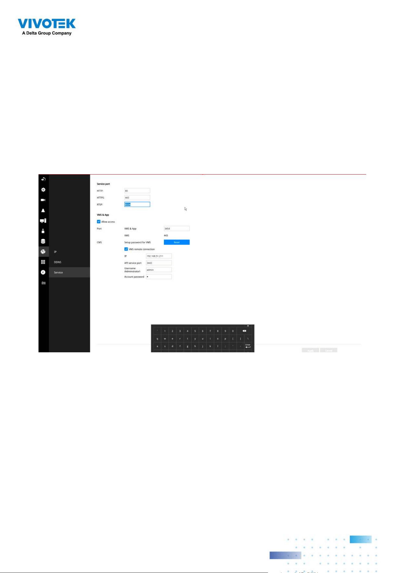
190190
4-11. Settings > VIVOCloud
If users have an existing VIVOCloud account, they can join their current configuration with
VSS, such as an NVR and the cameras managed by it.
The precondition is, you must allow the NVR to be accessed from a VSS server. Open a
console to the NVR, and enter IP > Service, to click on Allow access.
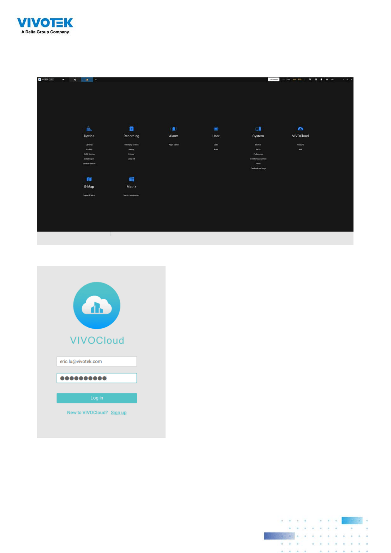
191191
Log in using your VIVOCloud credentials.
On the VSS client, click Settings > VIVOCloud.
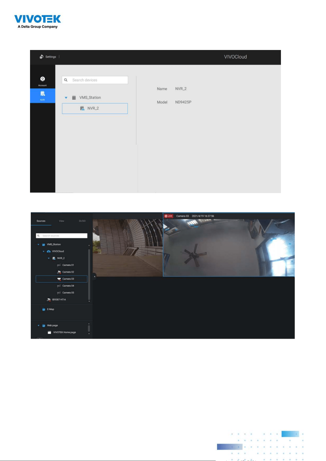
192192
The NVR will be listed under the VIVOCloud device tree.
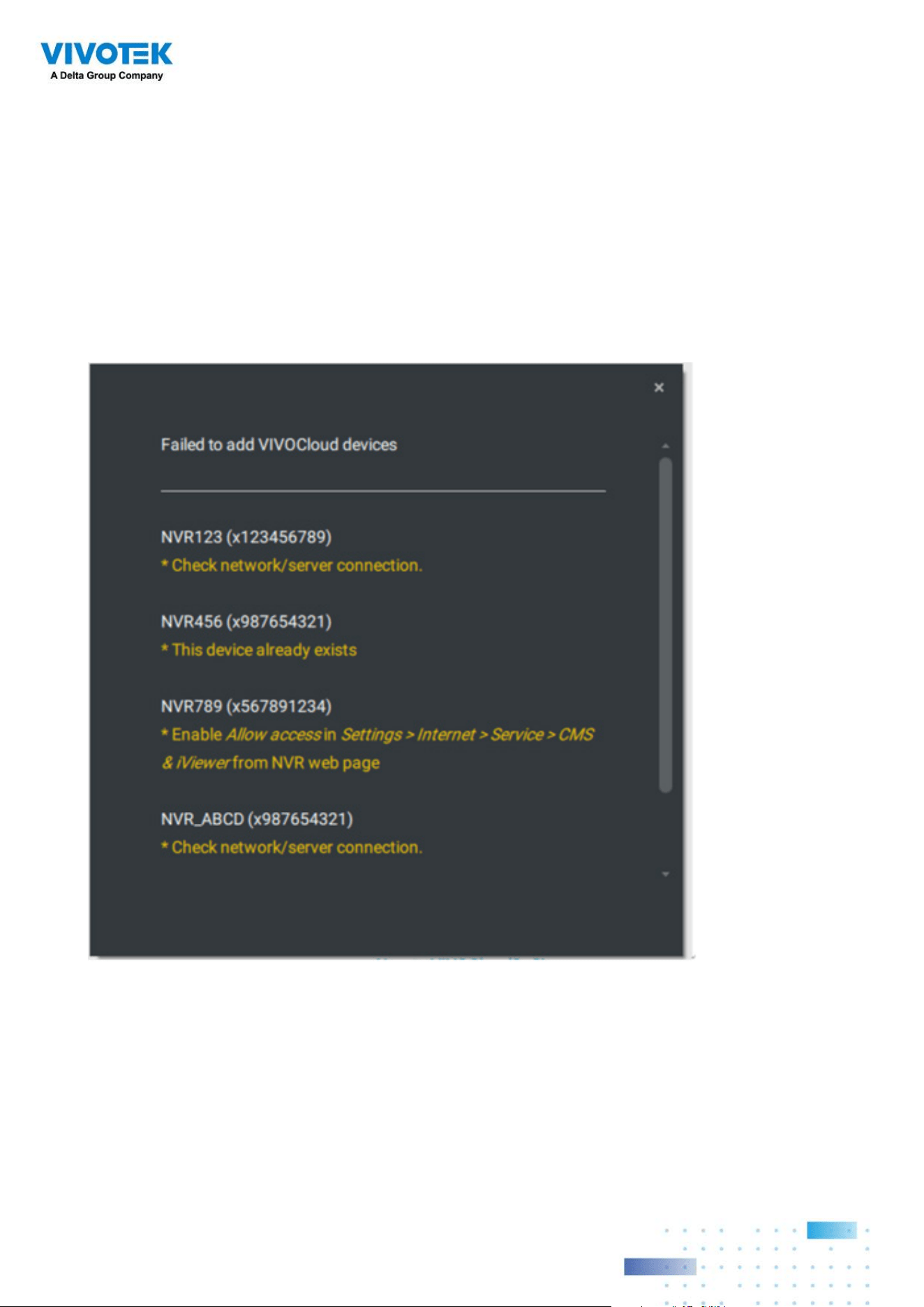
193193
If the NVR managed through the VIVOCloud is connected via a local or P2P network, the
connection should be normal. If the NVR is connected through VIVOCloud Relay, a 28
minutes timeout will be imposed, and you can use the connect button to re-connect.
You can encounter this message with connection problems or you did not allow the access
from a VSS server. You have to log out your VIVOCloud account and log in again after you
solve the above problems.
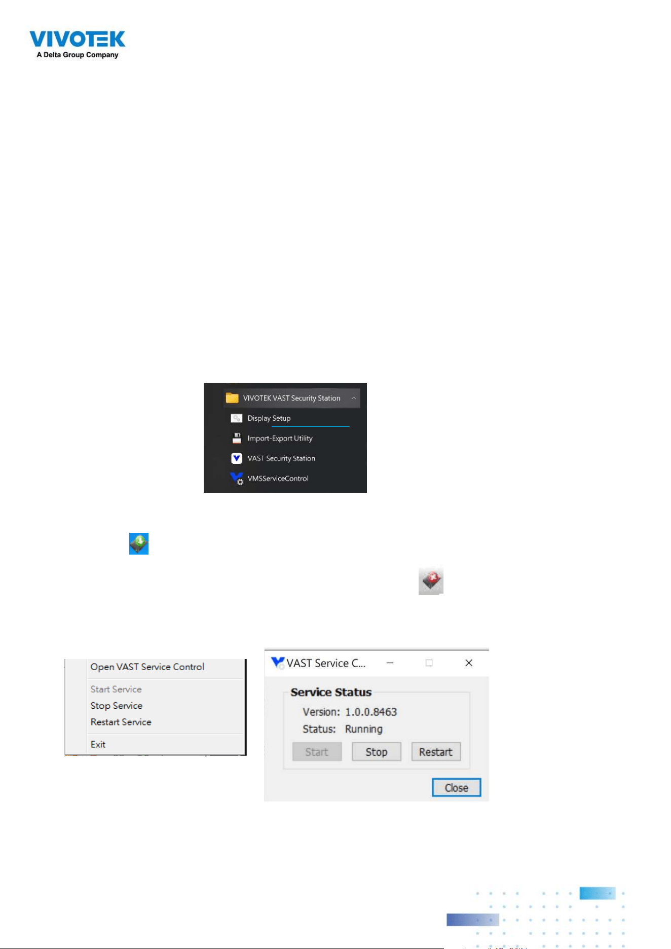
194194
Appendix A: VSS Service
Control Tool
VSS service control tool is a tool for server control and for user to be aware of the VSS
Server status. It starts up as Windows OS startup.
Under Microsoft Windows, choose "Start > All Programs > VIVOTEK Security Station >
VMServiceControl."
You may also find it in the system tray icon of the tool bar, which indicates that the service
is running:
It shows a disconnection icon when the service is stopped:
A menu for the service control tool will pop up when you right-click on the icon:
Here you can manually start, stop and restart the service.
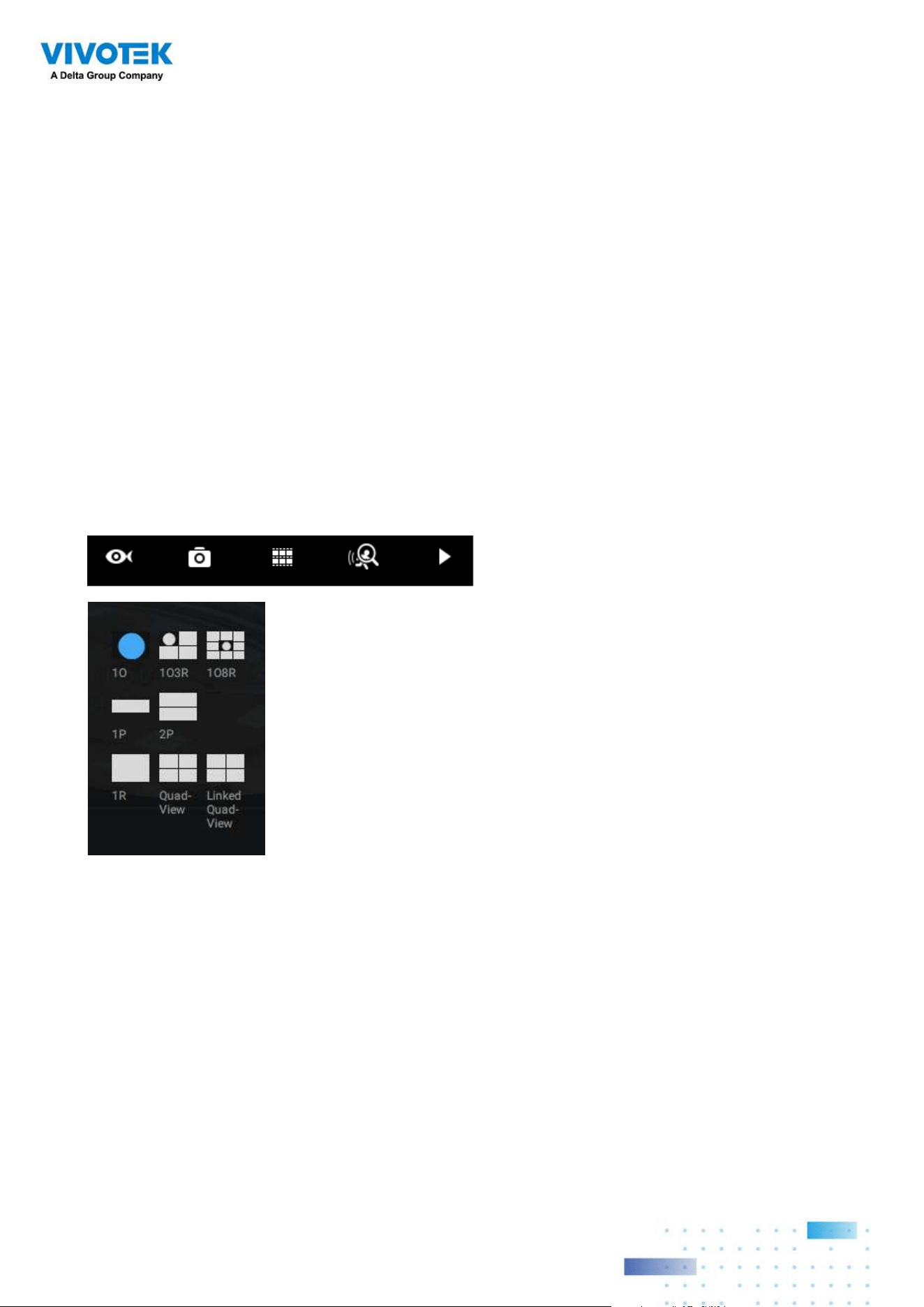
195195
Appendix B: Fisheye
Camera Dewarp Modes
By default, a circular view is displayed when a fisheye camera is successfully connected.
To display Regional, Panoramic, or the combination of different views,
1. Mouse over the view cell of a fisheye camera.
2. The onscreen control panel will appear. Click on the Fisheye button.
3. The Dewarp mode pane will prompt. Select a dewarp mode.
The display modes available are: 1O (Original), 1P (Panoramic), 1R (Regional), 2P (2
Panoramic), 1O3R (1 Original & 3 Regional), 4R (Quad Regional), 1O8R (1 Original & 8
Regional), and 4R Pro (4 Proactive) modes.
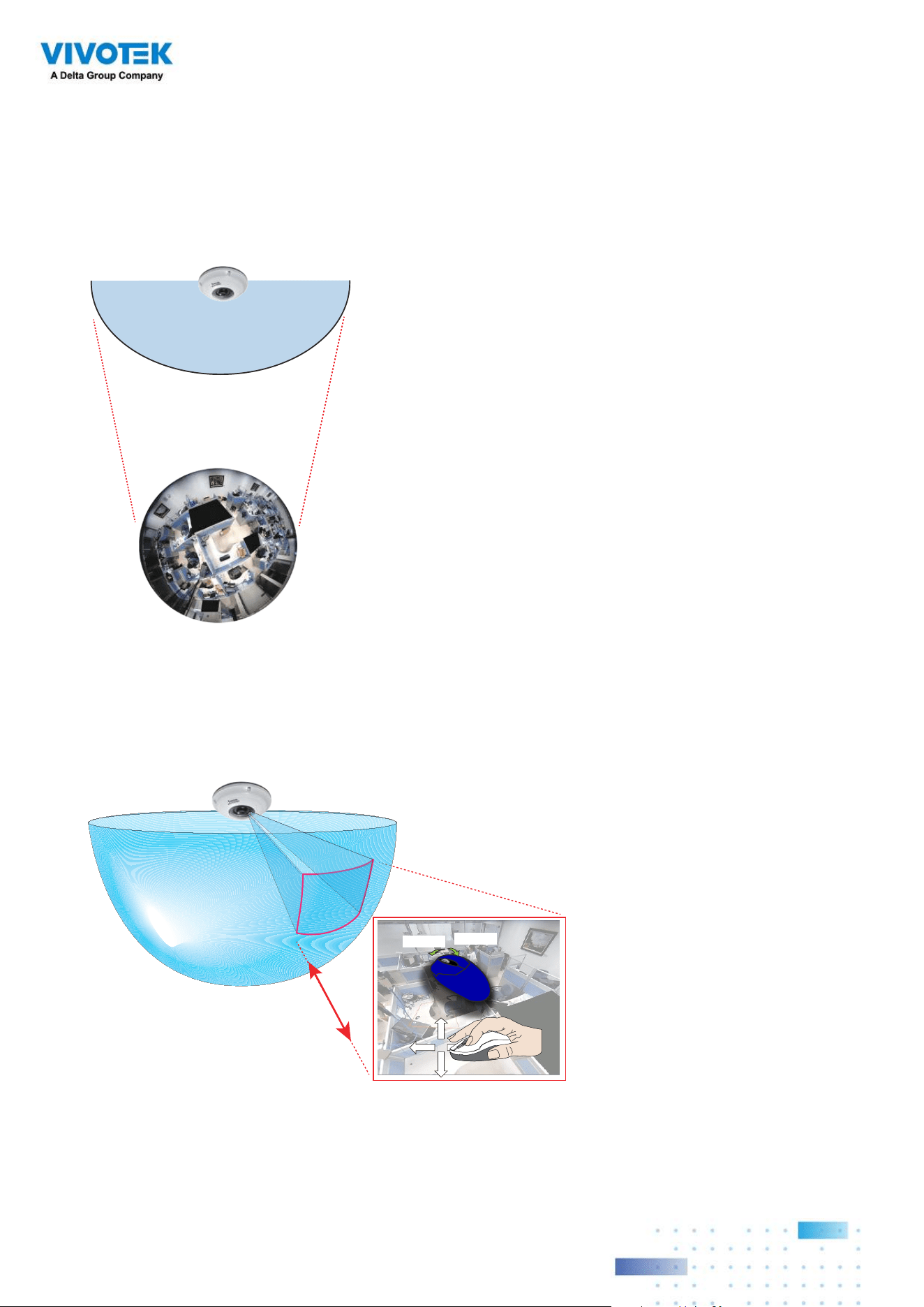
196196
Fisheye Display Modes: below are conceptual drawings for different display modes.
1O View (Original View)
180° Hemispheric
1R View (Single Regional View)
Zoom in/out
&
all-direction
navigation control
Zoom In
Zoom Out
An Original oval view covers the hemisphere taken by the fisheye lens.
A Regional view crops a portion of the hemisphere as a region of interest. You can zoom in
or out or move the view area elsewhere from on the regional view.
A Regional view is dewarped, by correcting images from the distorted oval view to a
rectangular and visually proportional image.
1O (Single Original) Display mode:
1R (Single Regional) Display mode:
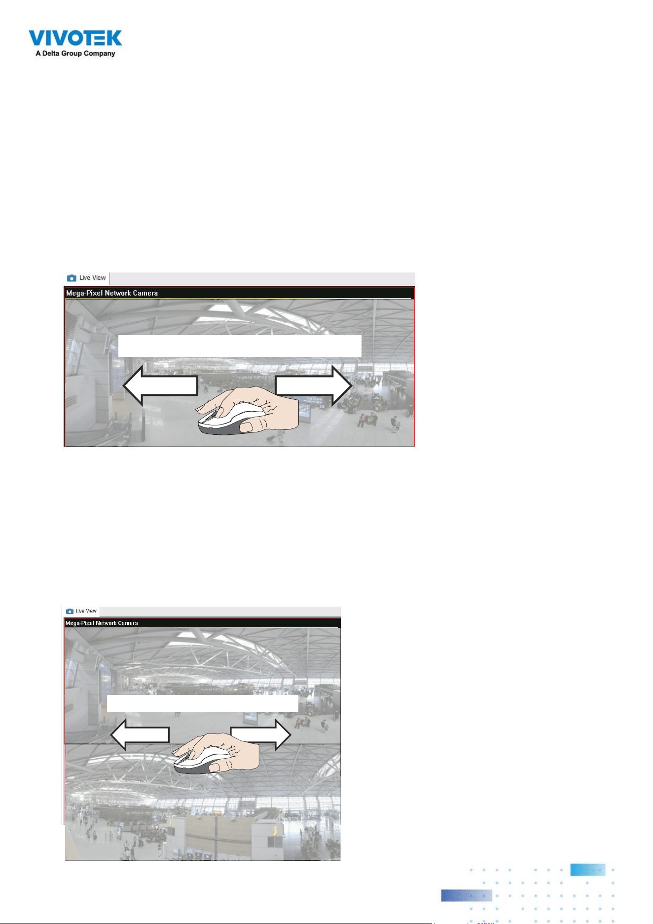
197197
Swipe to scroll horizontally
1P (Single Panoramic) Display mode:
With image correction algorithms in firmware, the hemispheric image is transformed into
a rectilinear stripe in the 1P display mode. Viewers can use the PTZ panel or simply use
mouse control to quickly move through the 360º panoramic view.
Note that the 1P view is apt for an overview, the Zoom in/out function does not apply in
this mode.
1P (Panoramic) Mode Screen Control
Swipe to scroll horizontally
2P (2 Panoramic) Display mode:
Two dewarped rectangular views are placed one on top of another each showing 180
degree of panoramic view. The 2P view looks like the upper view shows the front of
hemisphere, and the lower view the rear half of the hemisphere.
2P (Panoramic) Mode Screen Control
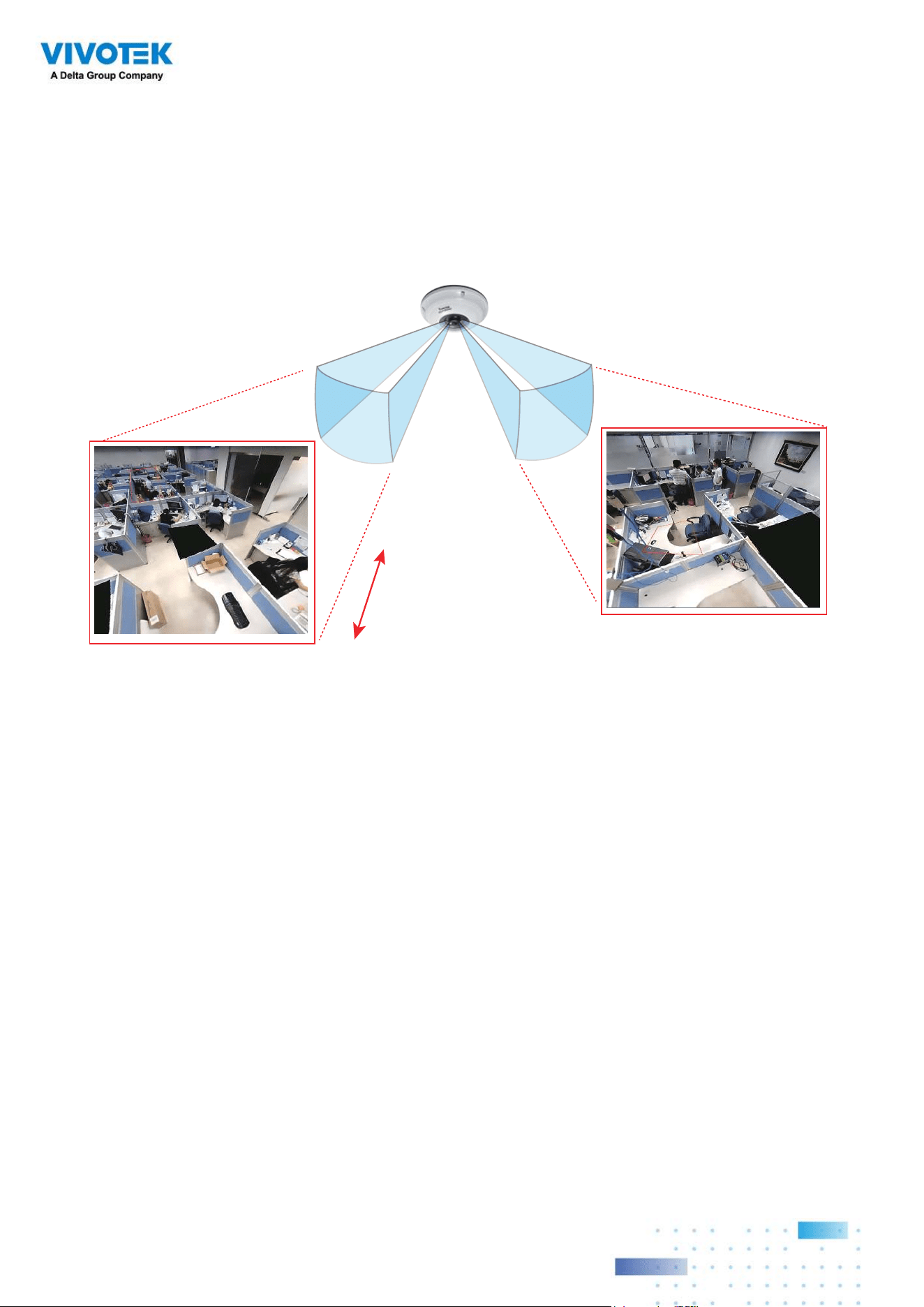
198198
Zoom in/out
&
all-direction
navigation control
* Only two regional views are shown for simplicity reason
Fisheye cameras also support the display of multiple regional views taken from within the
same hemisphere, and they can be displayed with or without an Original view in its view
cell.
3R View (Regional View)
1O3R (One Original & 3 Regional) Display mode:
NOTE:
The various display modes require the support of D3D technologies by your display card
on the LiveClient or Playback station. Most off-the-shelf display cards today support this
feature.
The onscreen mouse control is very agile. Therefore, use the PTZ panel for more delicate
moves in a field of view. Pan and Patrol moves are also supported if you have configured
preset PTZ positions in the camera's firmware. Note that the Pan move takes place in the
Panoramic and Regional views, while the Patrol function through preset positions applies
only in the Regional views.
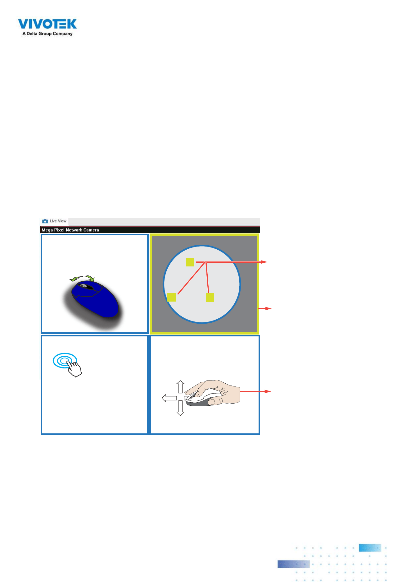
199199
PTZ Mouse Control
The "Mount type" setting also determines the display modes available to your display
modes. Please refer to fisheye camera's User Manual for more information.
A highly versatile mouse control is implemented with fisheye cameras. The same control
takes effect on a browser management session, on the LiveClient utility, and even on a
video playback screen. See the drawing below for how it works.
You can click and hold down the left mouse button to quickly swipe through the field
of view, change the view angle, or use the mouse wheel to zoom in/out on a region of
interest. However, the PTZ mouse control is only available in the "R" (Regional) mode. In
the Panoramic mode, you can only scroll horizontally across the 180º or 360º panoramic
view.
Current screen selection
Zoom In
Zoom Out
Click to bring into
center of view
Pan or tilt
1
2
3
Interactive
regional FOV indicators
Click and hold down
the button
1O3R (Original & Regional) Mode Screen Control
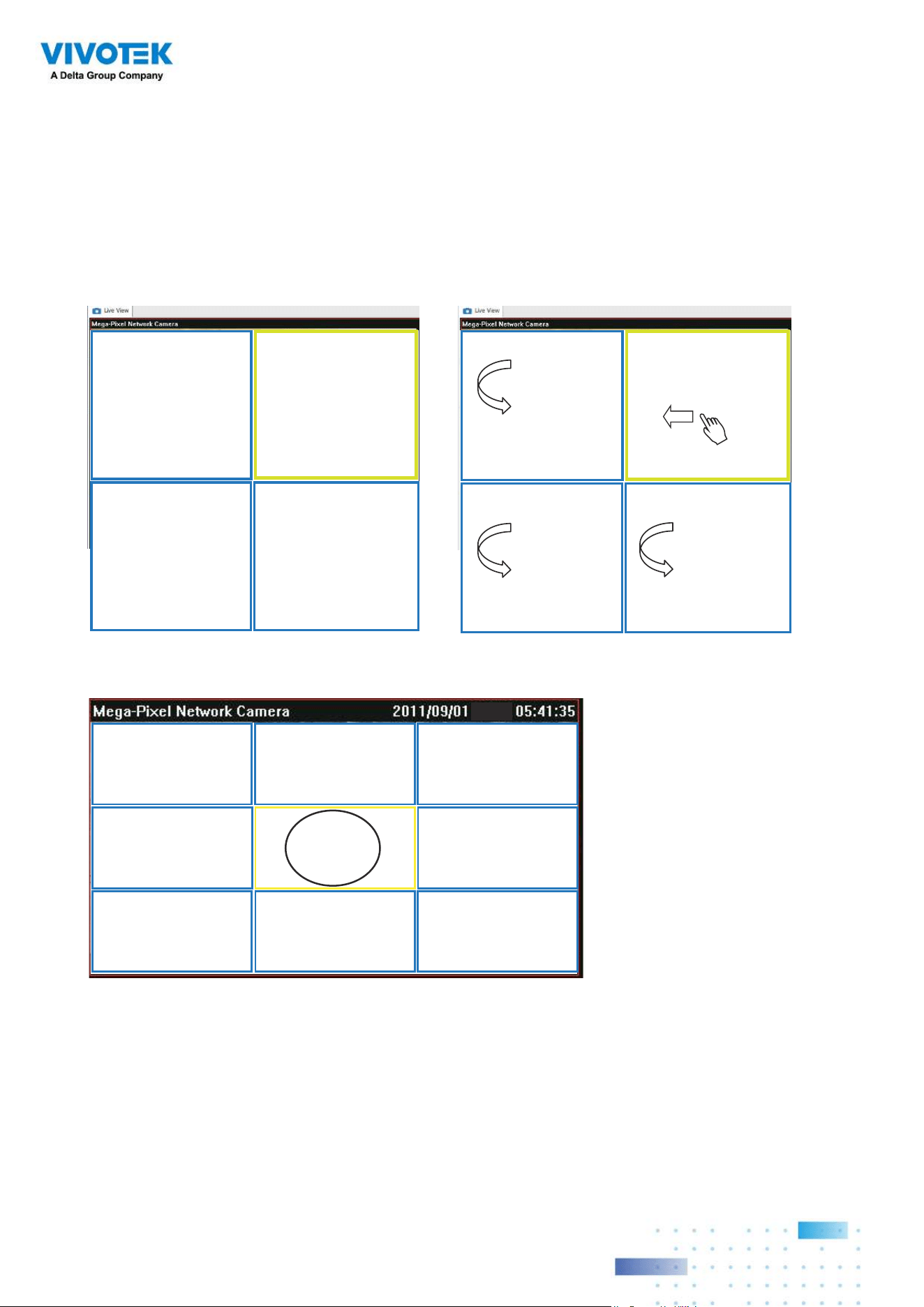
200200
Regional View #1
Regional View #3
Regional View #2
Regional View #4
Regional View #1Regional View #2
Original View
Regional View #3
Regional View #6Regional View #5 Regional View #7
Regional View #4 Regional View #8
Regional View #1
Regional View #3
Regional View #2
Regional View #4
Below are the conceptual drawings for the other display modes. The available display
modes can differ with different mount types:
Regular: 1O, 1P, 1R, 1O3R, 4R.
Wall mount: 1P2R, 1P3R.
For more information, you can refer to fisheye camera's user documents.
4R (Quad Regional) Display mode:
1O8R (One Original & 8 Regional) Display mode:
4RPro (4 Regional Proactive) Display mode:

201201
3rd-party Fisheye Dewarp
Via manual calibration, users can utilize dewarp functions for 3rd-party fisheye cameras
through the Enable fisheye lens dewarping, and select a mount type. You can then align the
blue cirlce with the fisheye's circular view.
When the calibration is done, you can select different dewarp modes in VSS using the
transition button on the upper right of the view cell.
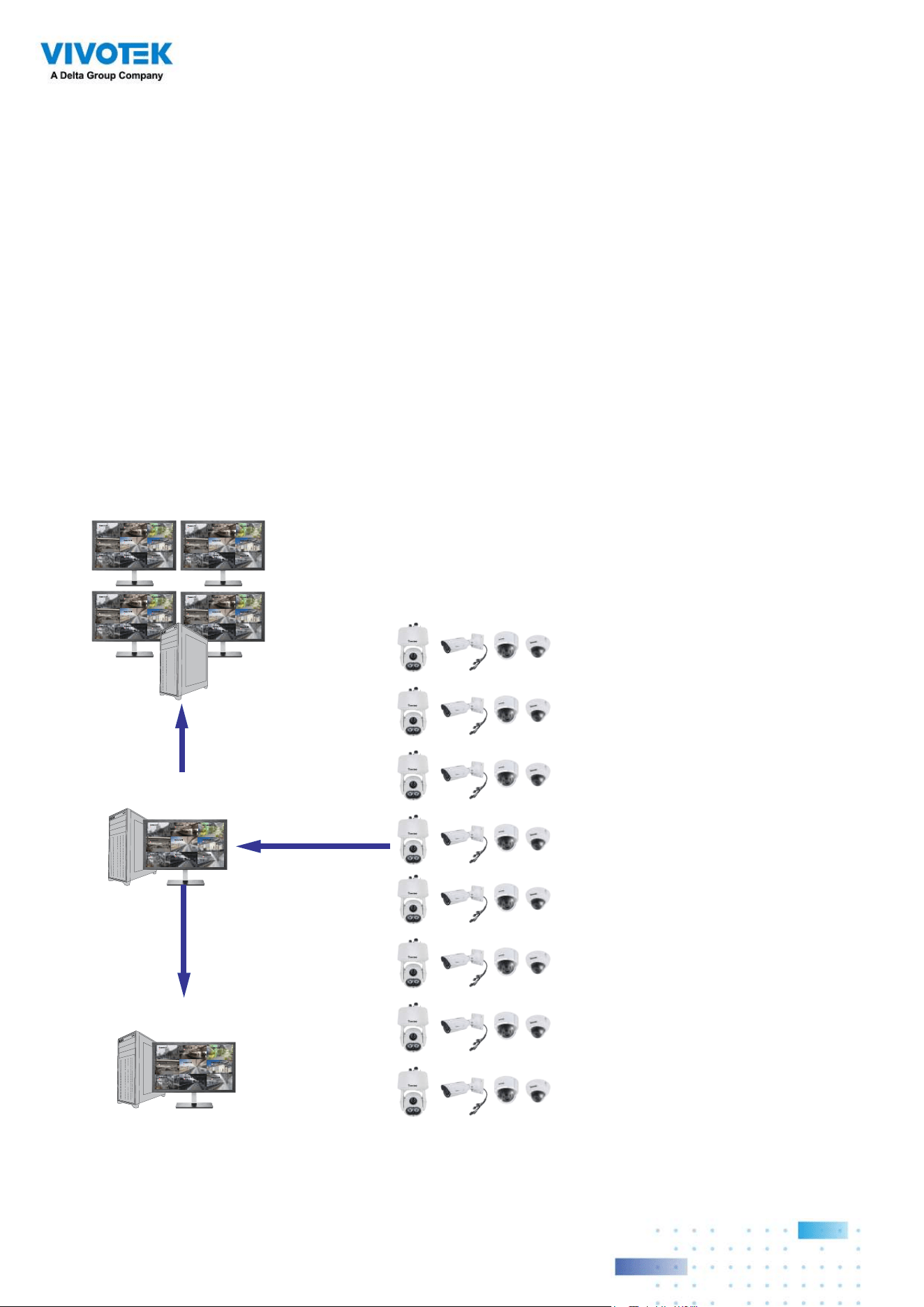
202202
Appendix C: Matrix
Camera 01
Camera 02
Camera 03
Camera 04
Camera 06
Camera 05
Camera 07
Camera 08
Camera 09
VSS Server
Camera 01
Camera 02
Camera 03
Camera 04
Camera 06
Camera 05
Camera 07
Camera 08
Camera 09
Camera 01
Camera 02
Camera 03
Camera 04
Camera 06
Camera 05
Camera 07
Camera 08
Camera 09
Camera 01
Camera 02
Camera 03
Camera 04
Camera 06
Camera 05
Camera 07
Camera 08
Camera 09
Camera 01
Camera 02
Camera 03
Camera 04
Camera 06
Camera 05
Camera 07
Camera 08
Camera 09
VSS Matrix
Camera 01
Camera 02
Camera 03
Camera 04
Camera 06
Camera 05
Camera 07
Camera 08
Camera 09
VSS Client
The virtual matrix feature enables the display of any cameras on any monitors in an
IP surveillance network. Combinations of live or playback streams can be displayed
simultaneously. In addition of pre-configured live views, E-maps, Google maps, and Alarm
panes can all be placed on a remote matrix. Users gain realtime awareness of scenes and
access to past events.
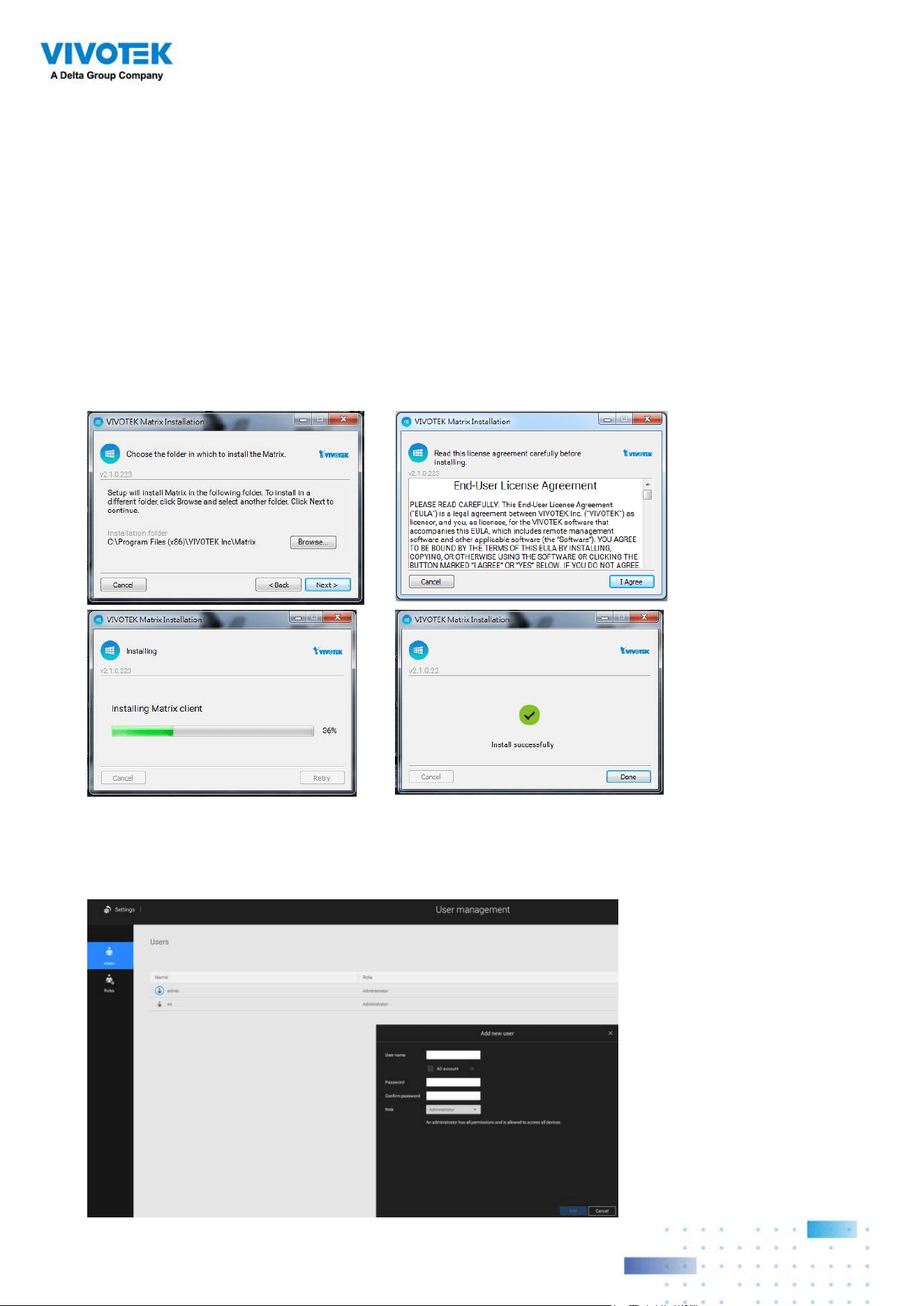
203203
Prerequisites:
1. One VSS server and another computer running the Matrix client utility.
2. The first 2 digits of software revision numbers of VSS server and Matrix client must be
the same: e.g., 2.3.x.x and 2.3.x.x.
3. Sufficient network bandwidth among network cameras, VSS servers, and Matrix clients.
Configuration procedure:
1. Install the Matrix client utility on a computer equipped with multiple monitors. Follow the
onscreen instructions to install the utility.
2. On the VSS server, create a user account for the Matrix client. Depending on the
operation on the client computer, assign the client user with adequate operation
privileges.
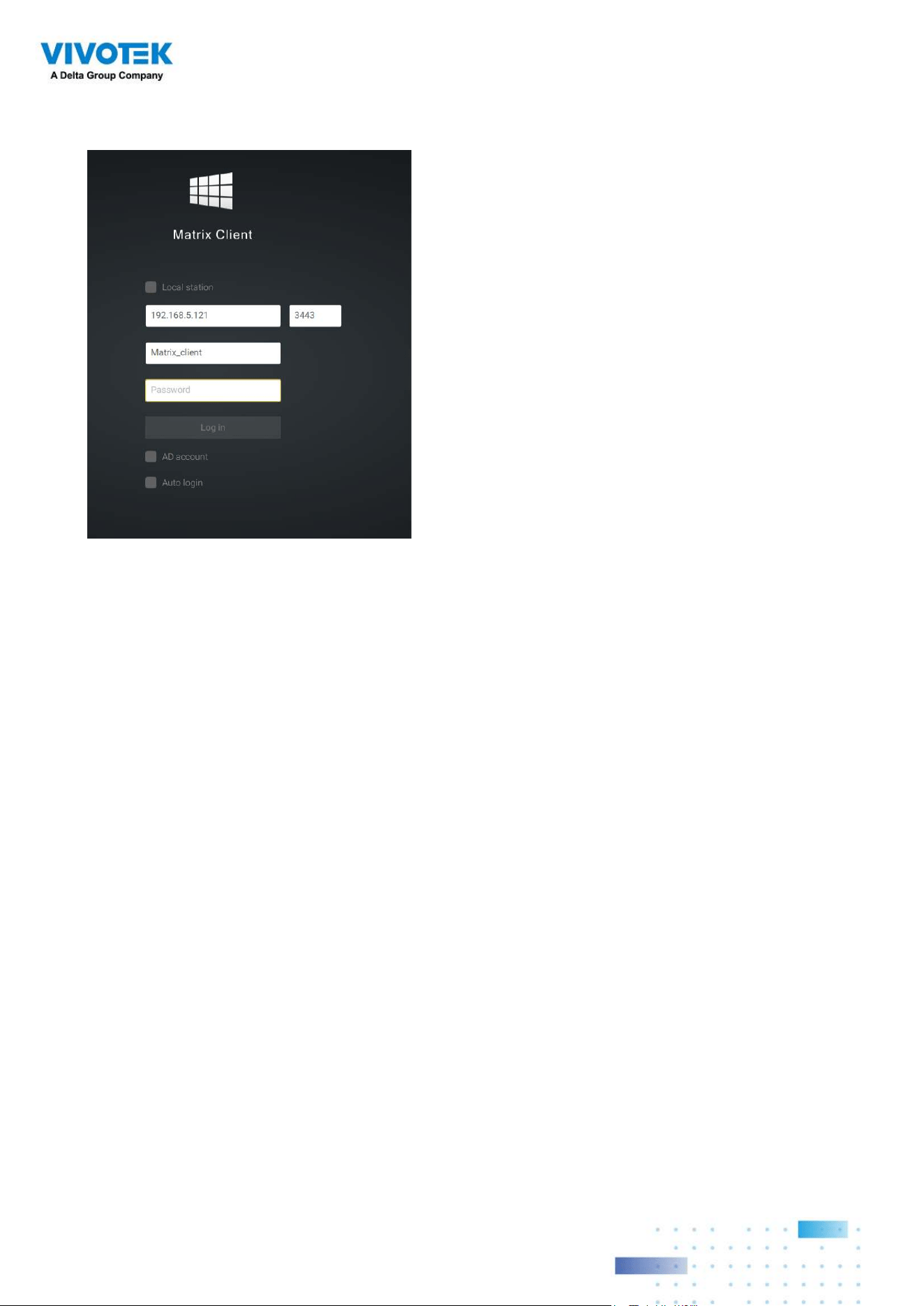
204204
3. Open the Matrix utility, log in to the VSS server address, using the Matrix client account
credentials.
4. From the VSS server, open the Settings > Matrix Management window.
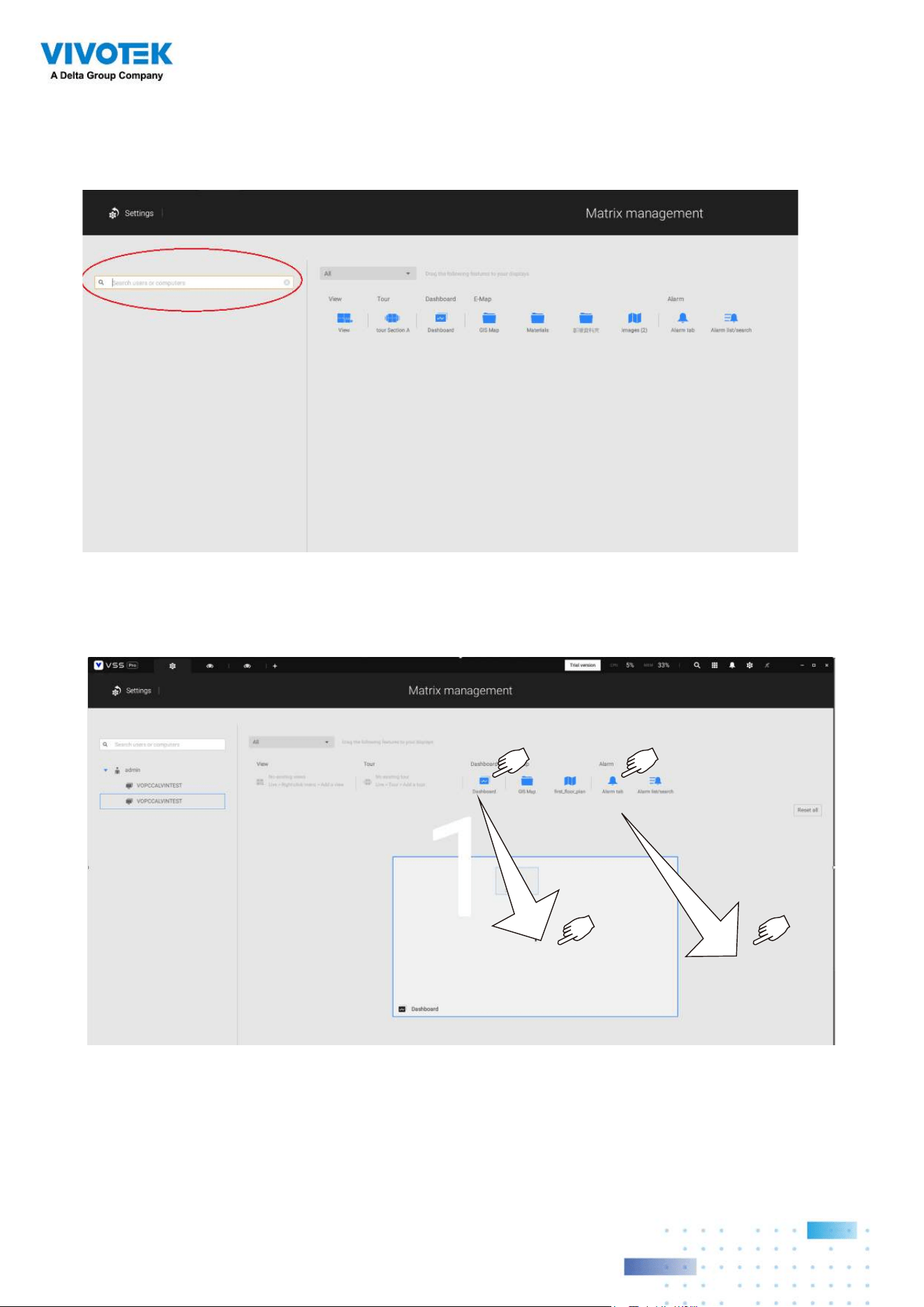
205205
5. Enter the name of your Matrix client, e.g., Matrix_client in the search pane of the Matrix
Management window. Note that the Matrix client must have logged in to establish the
connection before the VSS server can find it (as previously described).
6. Once the VSS server finds the Matrix client, the available monitors will be listed. Click
and drag the pre-configured Views, Tour, Dashboard, E-maps, or Alarm panel to any of
the monitors.
7. The views should immediately appear on the Matrix monitors.
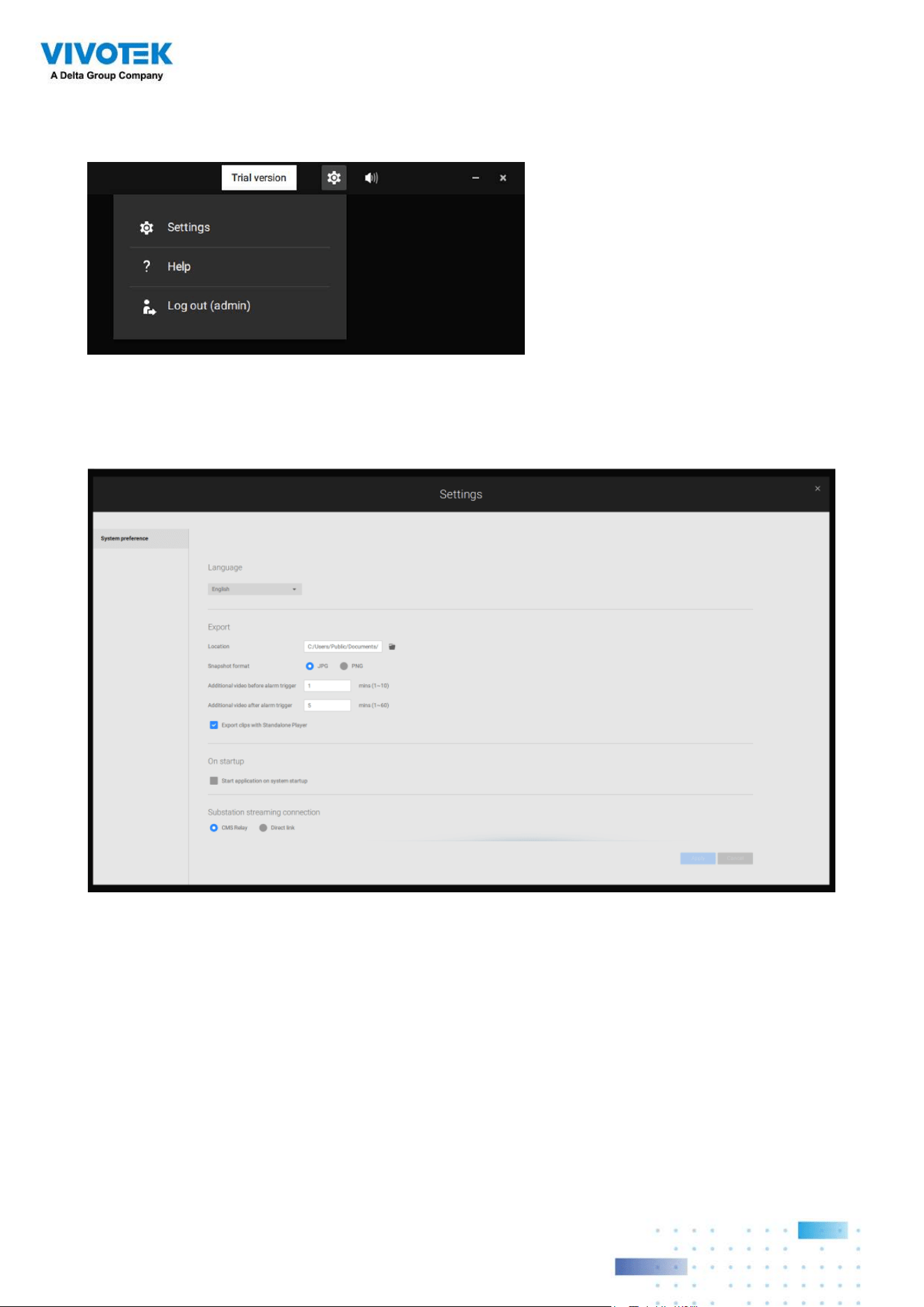
206206
8. If you need to log out, move your mouse cursor to the top of the Matrix client screen to
end the session.
If necessary, change your client settings. Here you can change the displayed language,
Export target folder, Start-up option, and the streaming connection options.
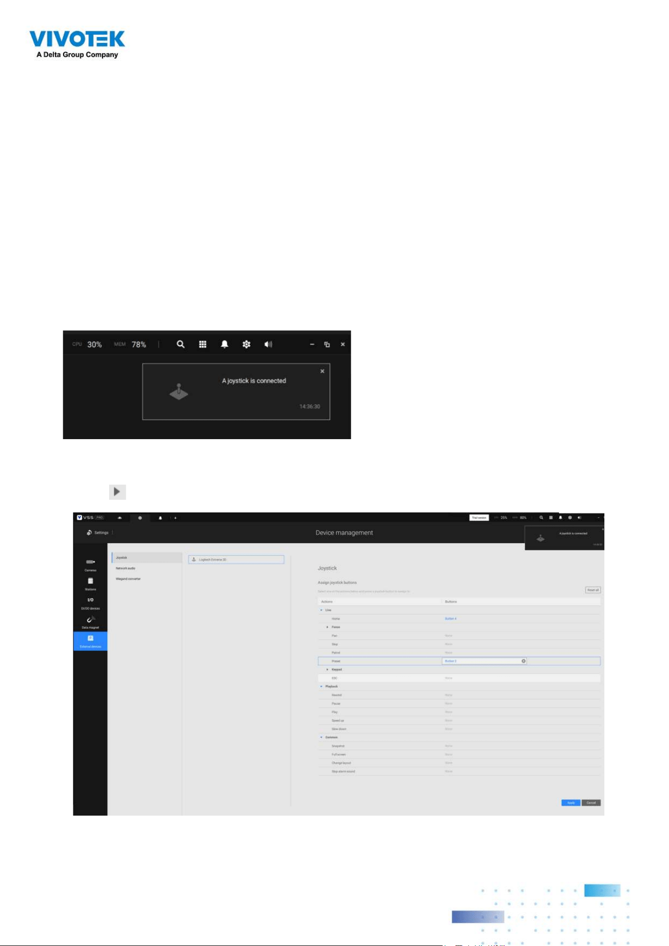
207207
Appendix D: Joystick
Support
Configurable joystick buttons
1. Connect the joystick's USB cable between the USB ports on the joystick and a VSS
server/client.
2. Once connected, you should be prompted by a connection message.
3. Enter Settings > Device > External devices.
4. Single-click to select the detected joystick. The configurable buttons will be listed.
Click
to expand the Live, Playback and Common menus.
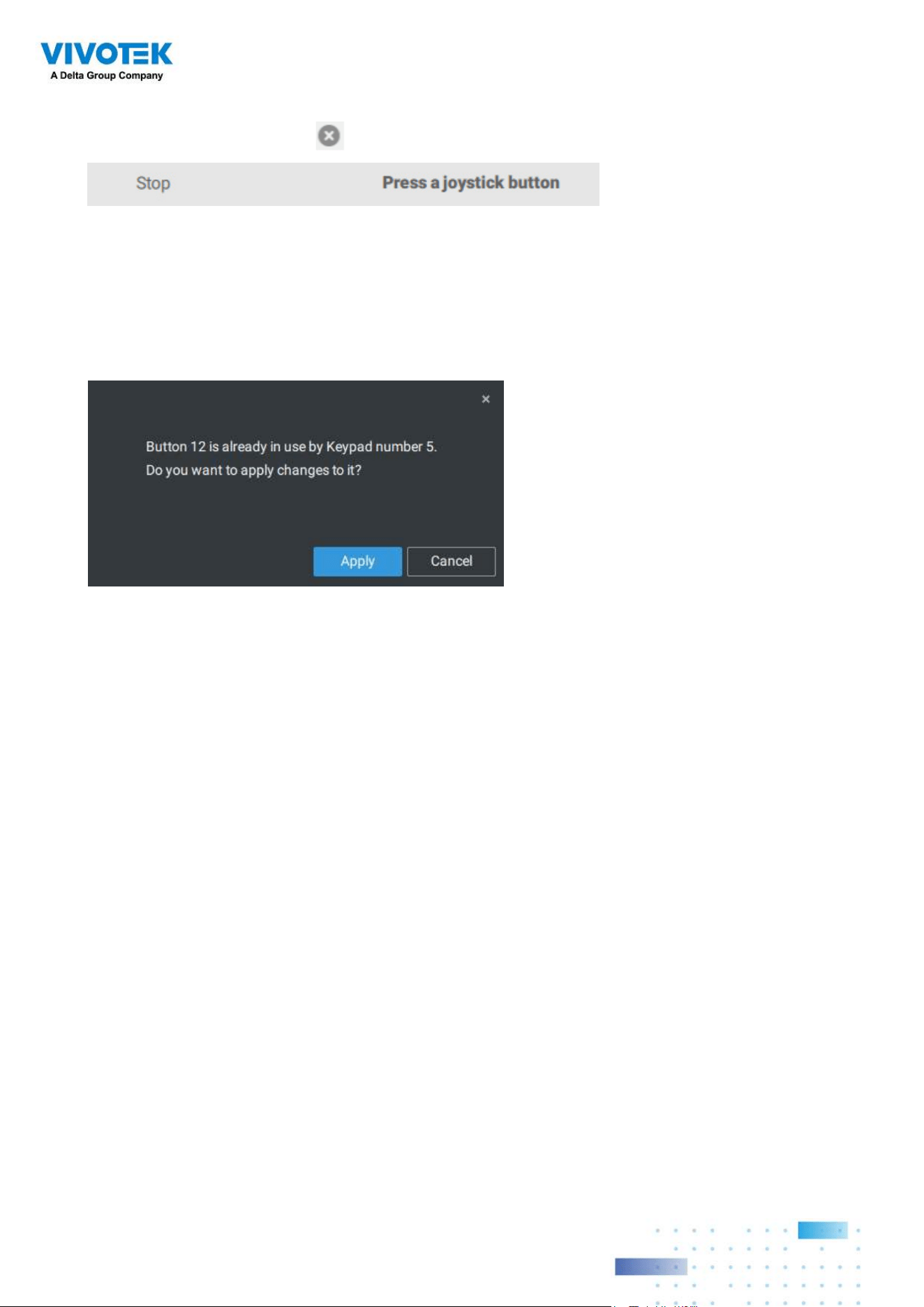
208208
5. To assign or re-assign a button's function, single-click on the button number besides a
function. Click the Delete
button. The below message will display.
Press a preferred button on your joystick to complete the setting.
If a button conflict occurs, (another function has already been assigned to the same
button), the below message will prompt. You can Cancel or click Apply to change the
assignment.
Repeat the above process and click the Apply button to preserve your settings.
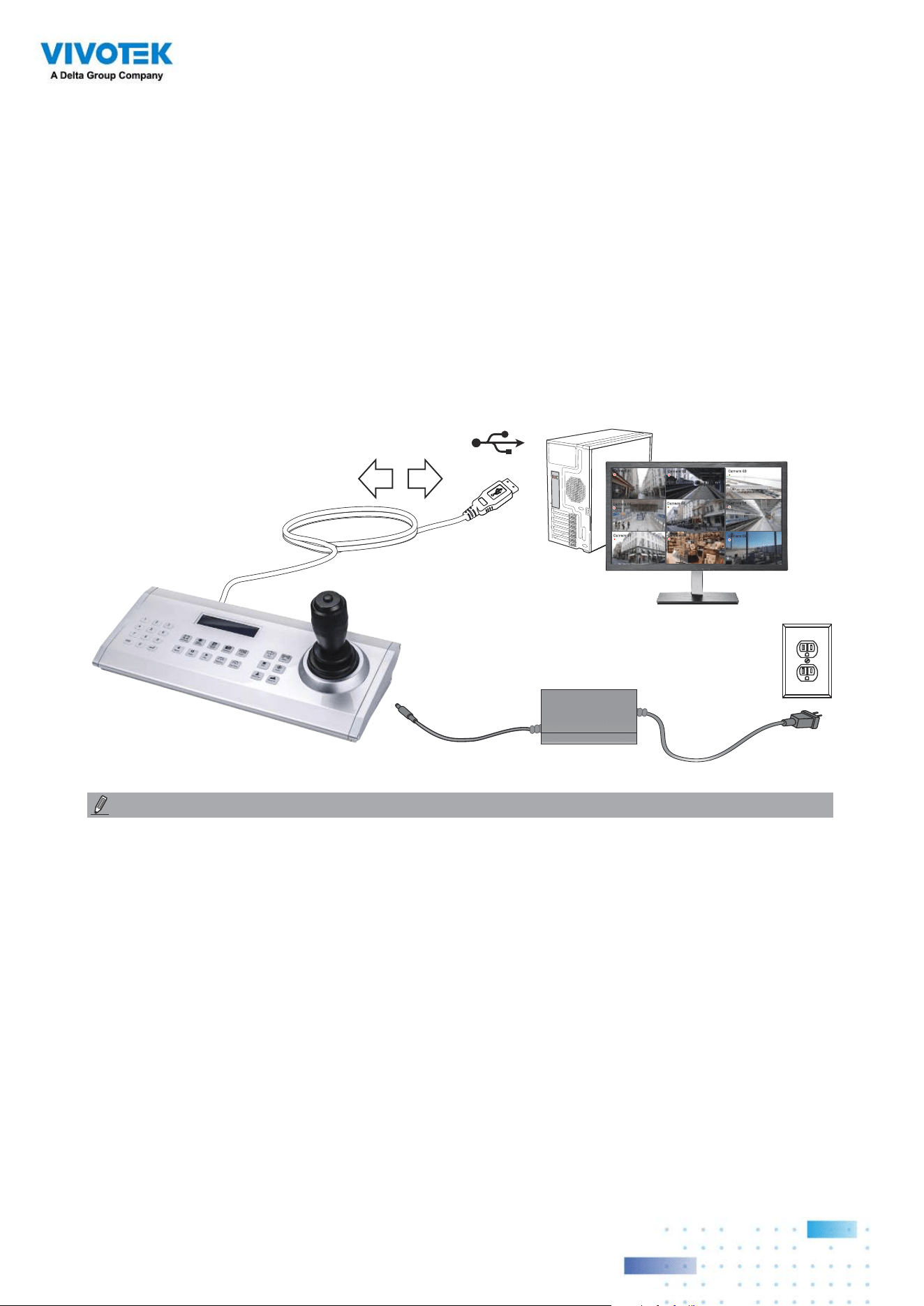
209209
Camera 01
Camera 02
Camera 03
Camera 04
Camera 06
Camera 05
Camera 07
Camera 08
Camera 09
X2
VSS
12V DC
The AJ-002 is a USB joystick with HID 3-axis PTZ control, a twist wheel for zoom in/zoom
out, and 29 configurable function buttons for use on a VSS server station.
Following are the conditions for making the connection:
1. The joystick can either be powered by a DC 12V adaptor or via the USB. If powered by
USB, plug the USB cable twice to the USB port to enable USB power.
2. Connect the included USB cable between the USB ports on the joystick and a VSS server.
1. Avoid spilling water onto the device. Avoid using this device in a high-moisture
environment.
2. This device should be operated in the indoor environment.
3. When the temperature is lower than -10ºC, the LCD panel may not function normally.
4. If the included power adapter should be replaced, use a 9-15V/1000mA alternative.
5. Avoid impact to the device.
6. This product is manufactured to comply with the requirements of the following
directives: 89/336/EEC, 92/31/EEC, 93/68/EEC.
NOTE:
VIVOTEK's joysticks
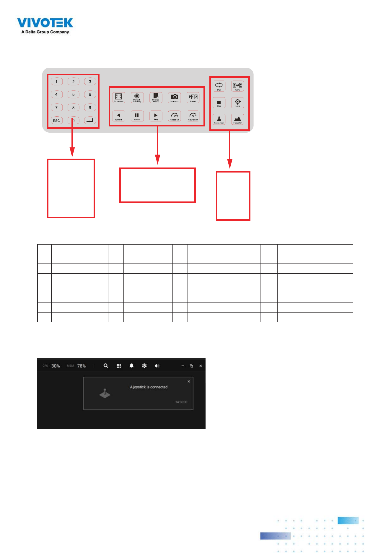
210210
KEYPAD DEFINITION
1 2
3 4
5 6
8
28
21 22
24 25
23 7
26 27
9 10
12 13
11
14
15 16
18 19
17
20
Below is the keypad numbering sequence:
The following keypad functions will be available as the defaults for the joystick.
1 Pan 9 #1 17 #9 25 Pause
2 Patrol 10 #2 18 Cancel/Clear/Esc 26 Play (Playback)
3 Stop 11 #3 19 #0 27 Speed Up
4 Home 12 #4 20 Enter 28 Speed Down
5 Focus Near 13 #5 21 Full Screen
6 Focus Far 14 #6 22 Manual recording
7 Snapshot 15 #7 23 Change Layout
8 Preset 16 #8 24 Rewind
When a joystick is connected, the VSS server should automatically detect the connection.
The following controls are available:
* PTZ control – Basic PTZ control: Direction, Home, Zoom in/out, and Focus near/far.
* Playback control – Play, Pause, Stop, Rewind, Speed up and Slow down.
* View switch – Switch to existing View (Users need to create views first).
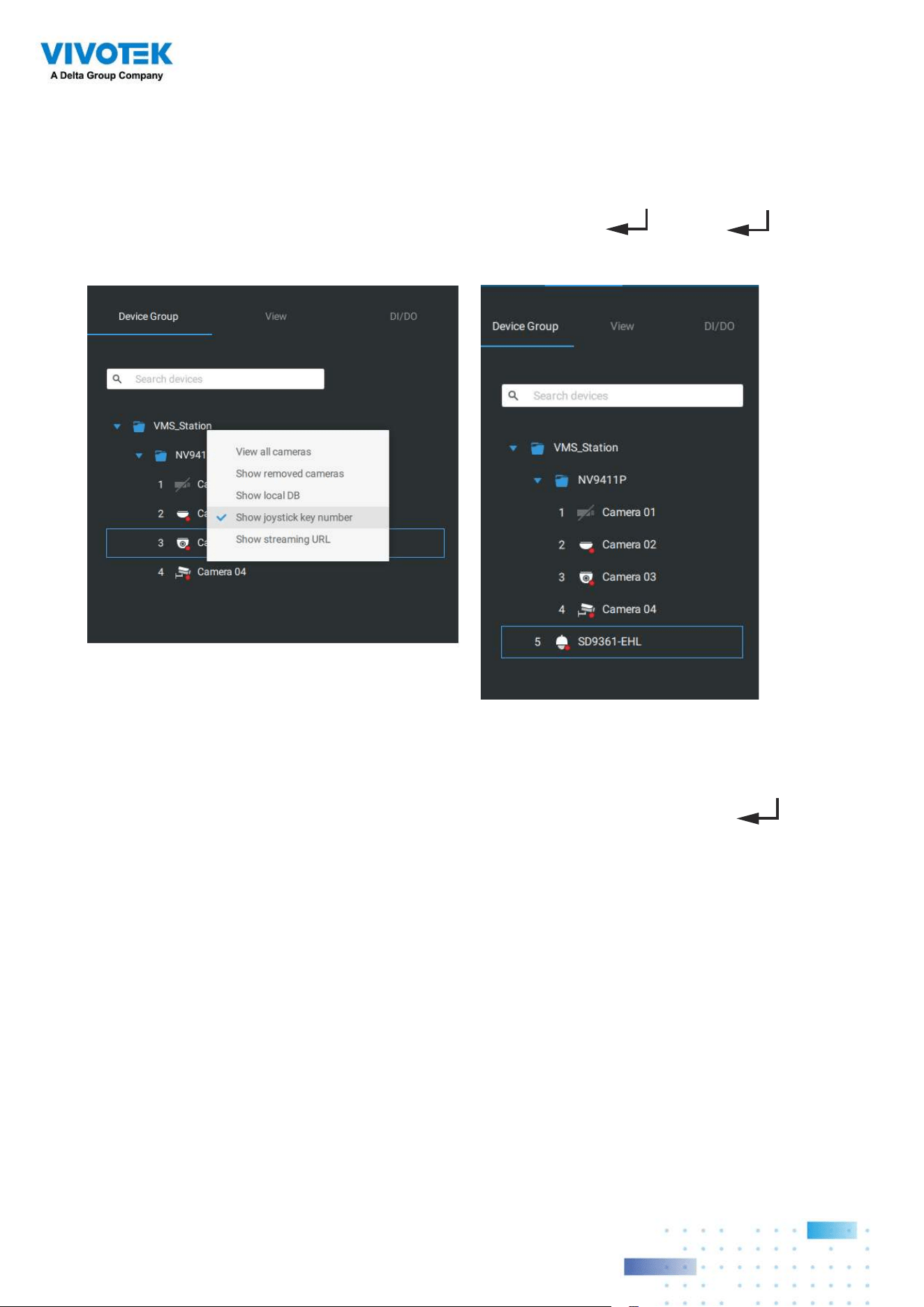
211211
Left-click to select your server on the device tree, and right-click to display and select the
"Show joystick key number." The camera key numbers are determined by the sequence
when the cameras were added to the VSS configuration, and cannot be changed. By
default, the key numbers are not shown.
Press the key number on the joystick keypad and the Enter key
, e.g., 5 + . The
full view of the selected camera will display.
Press the ESC key to leave the full view.
To move to a preset position, press the number key + Preset, and the Enter key . The
number key corresponds to the sequence number for the preset position regardless of the
name of the preset.
Note that the RS232/485 terminal connection is currently not supported.
Note that the Manual Recording button is currently not effective.
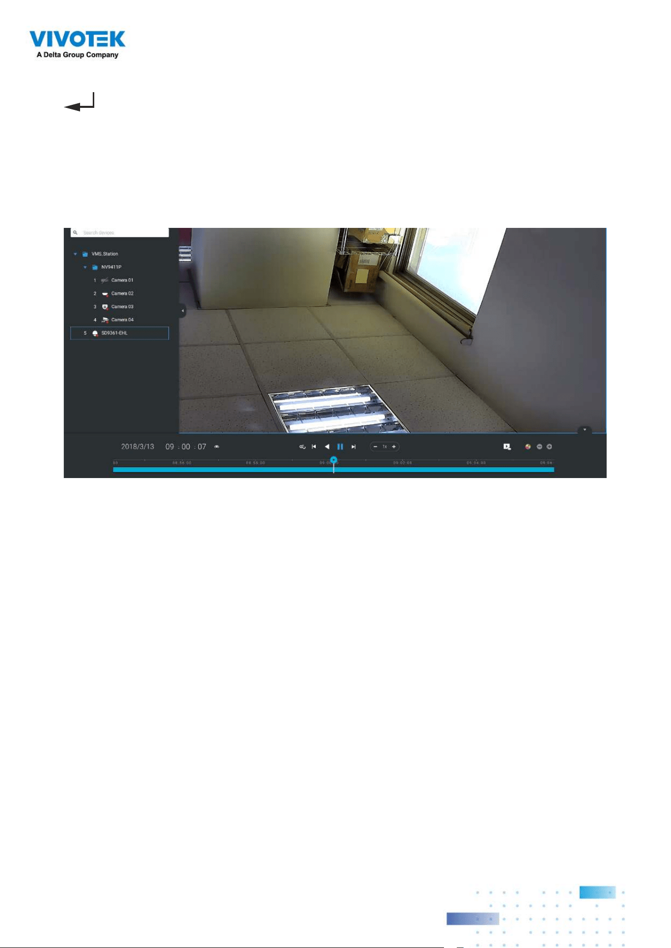
212212
If you have multiple views, press the number key and the Change Layout, and the Enter key
to switch to a different view. The number key corresponds to the sequence number
for the view you configured regardless of the name of the view (layout).
The Play button toggles the playback window. From here you can trace back the past
recordings. You can use speed up, slow down, and rewind buttons here. Once the Playback
mode is toggled, the point-in-time defaults to the start of the current hour.
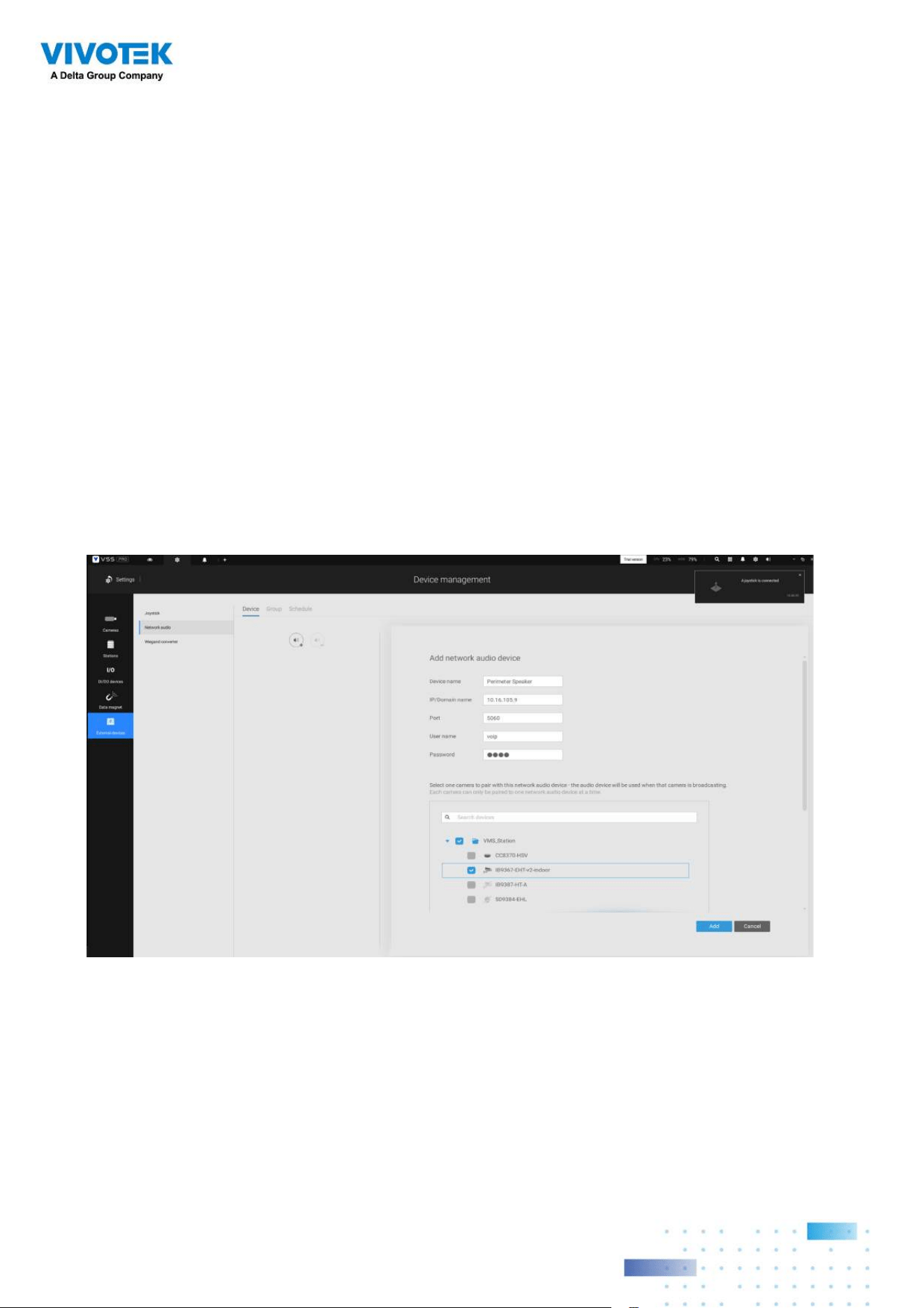
213213
1. Connect the network speaker to a local network.
2. Once connected, enter its IP address, User Name, Password, Port number (default is
5060).
3. You can associate one network camera with the speaker.
Appendix E: Network Audio
Solution
You can add network speakers to your workstation in Settings > External Devices >
Network Audio.
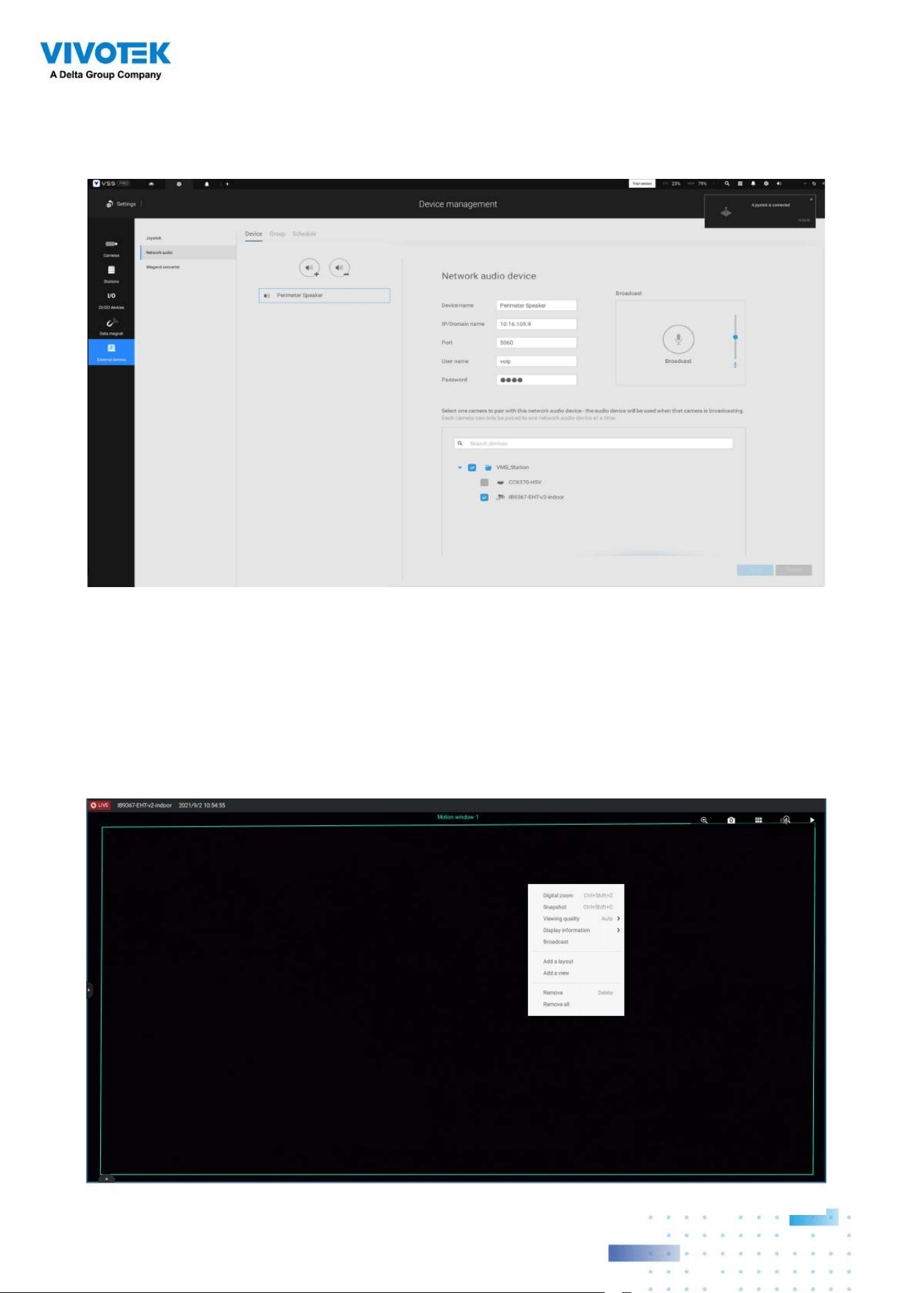
214214
4. You can use the Broadcast function on the right of the screen to test the connectivity.
5. You can right-click on the live view to find the Broadcast function to speak or broadcast
a audio clip.
6. On the occurrence of a triggered alarm (Motion or VCA event), you can configure the
alarm settings so that system can broadcast an audio clip. Configure audio clip settings
in System > Media, and select "Play audio file with network audio device" in the Alarm
action page.
Note that the pre-recorded audio clip should be uploaded from System > Media. The
supported audio file is WAV: 8Khz, Mono, 16-bit, PCM.
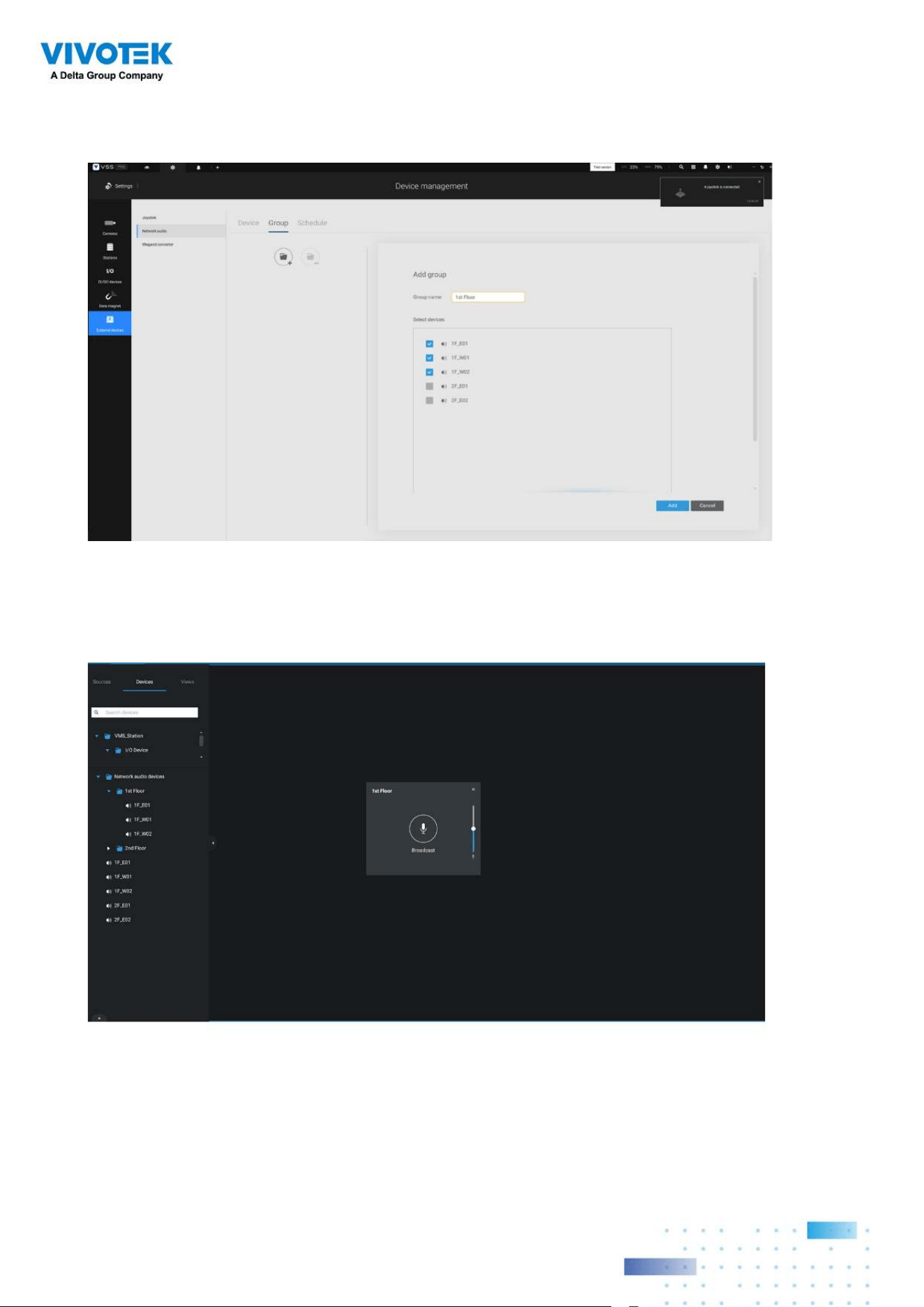
215215
You can create groups for different audio devices. Use the Group tab to create audio
groups. Select devices for the group.
With audio groups, you can select audio devices from the Devices tab on a live view so
that you can broadcast audios to a group of devices.
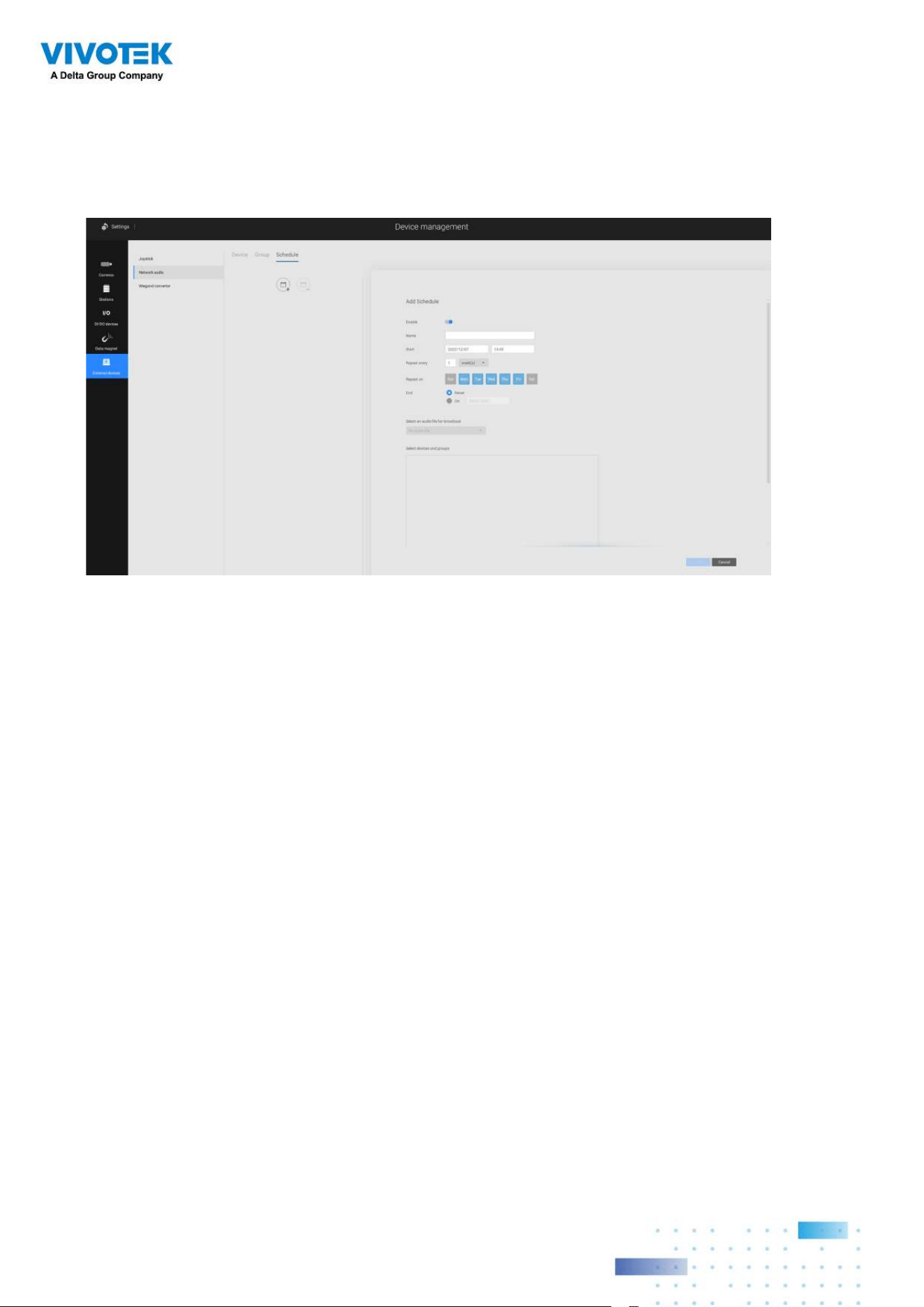
216216
You can create a schedule to play a pre-selected audio file. In Network aduio > schedule,
create a schedule. Select a start time. Select an audio file for broadcast. Select a
repeating pattern by hour, by day, or by the week days. You can also specify an audio
group to play by the schedule.
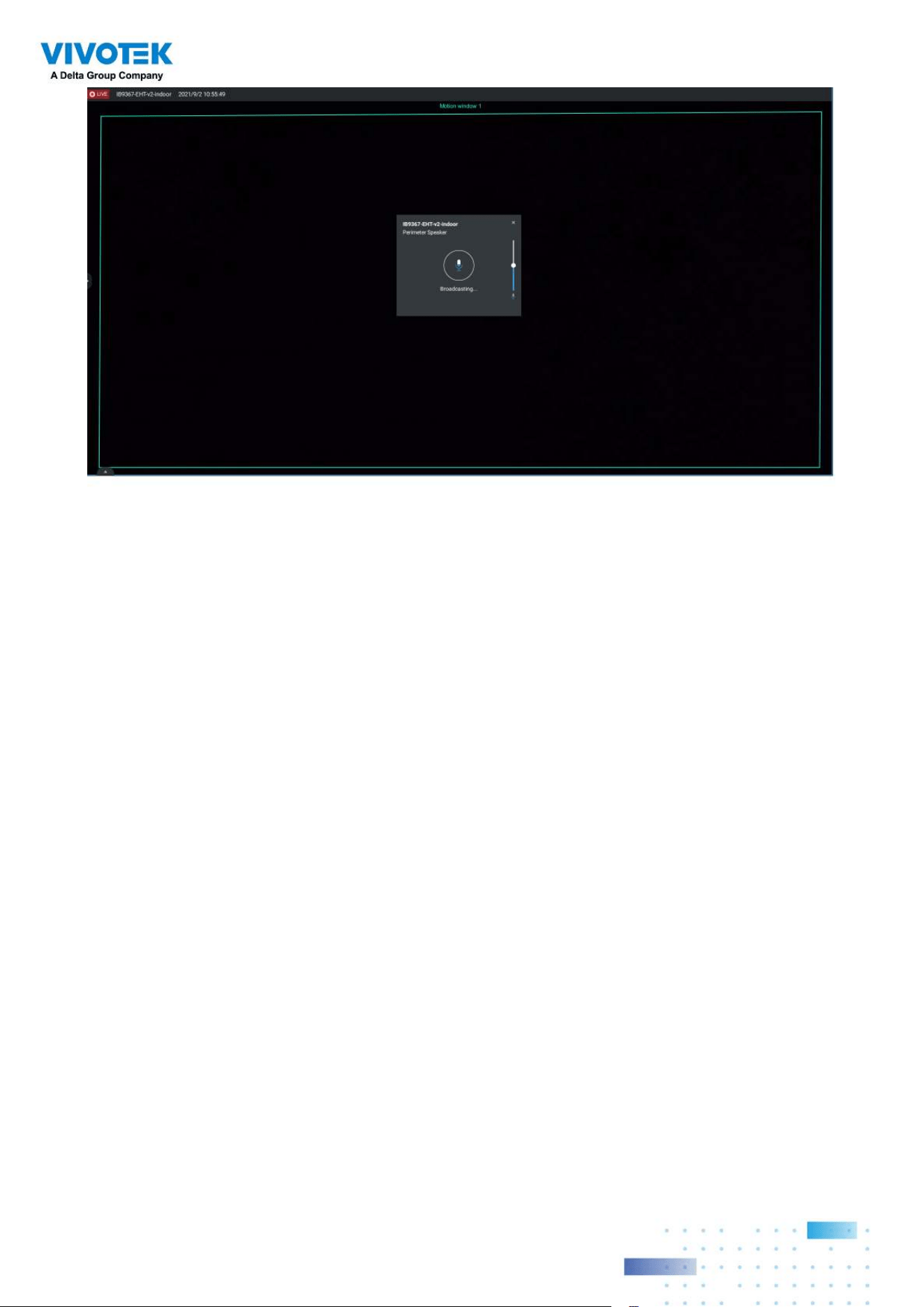
217217
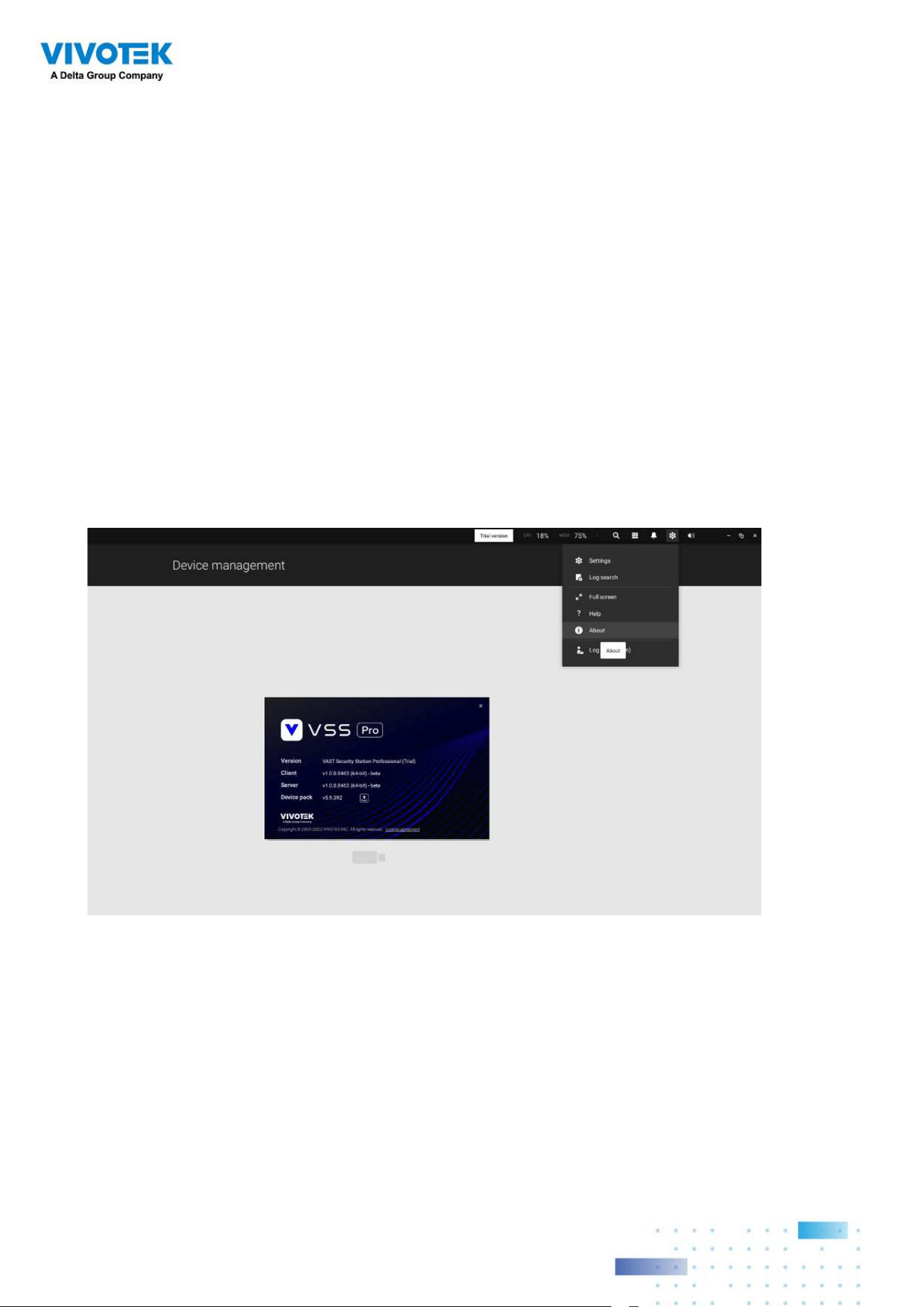
218218
Appendix F: Upload Device
Pack
A device pack is contantly updated for the latest profiles of VIVOTEK's new camera/NVR
models. If you install new cameras/NVRs to your configuration, you can visit VIVOTEK's
website for the latest device pack updates, and upload the pack file to your VSS server.
New functional parameters and functions in the new cameras are available through the
device pack.
Enter Settings > About to see the upload button.
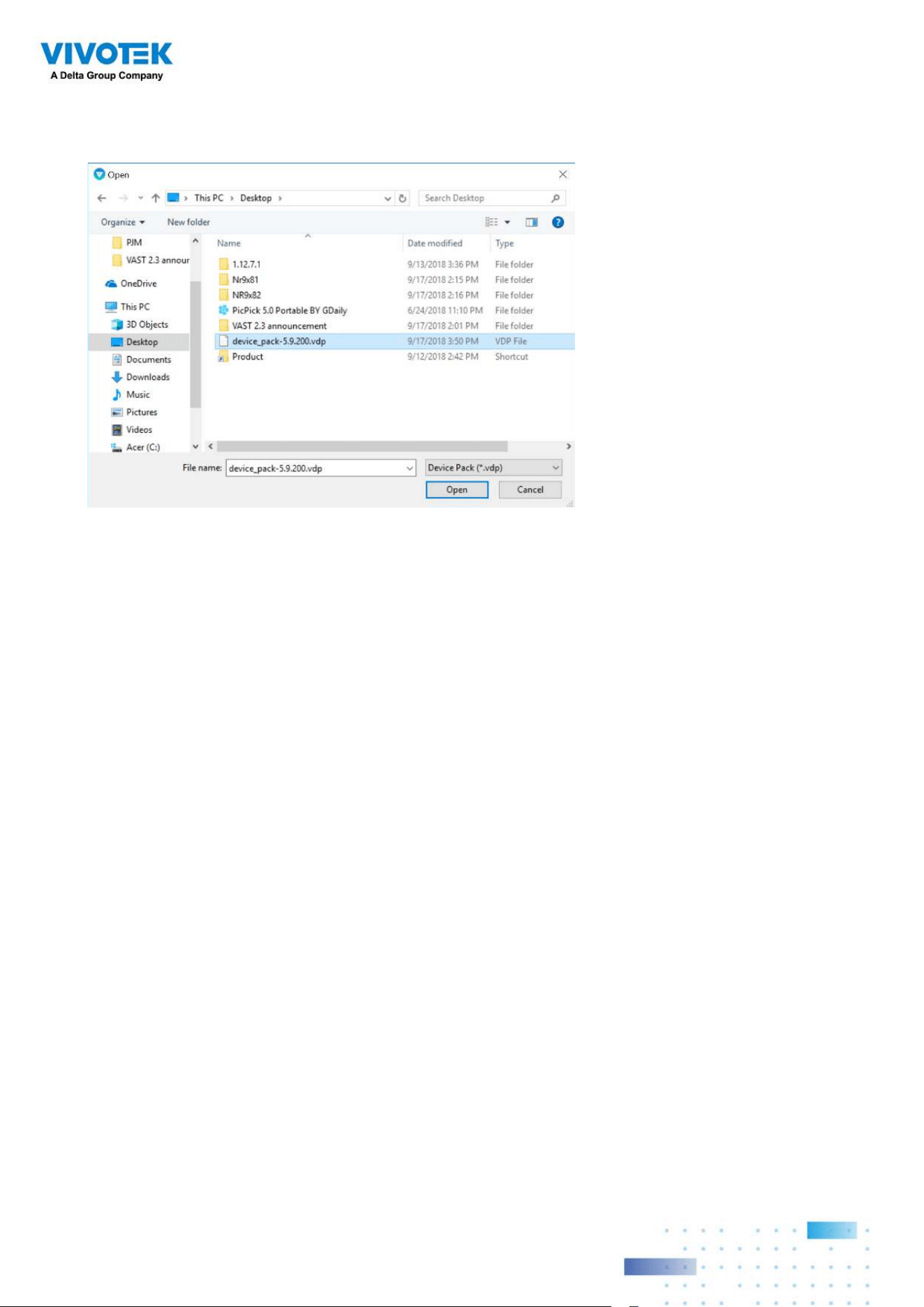
219219
A device pack file looks like the following.
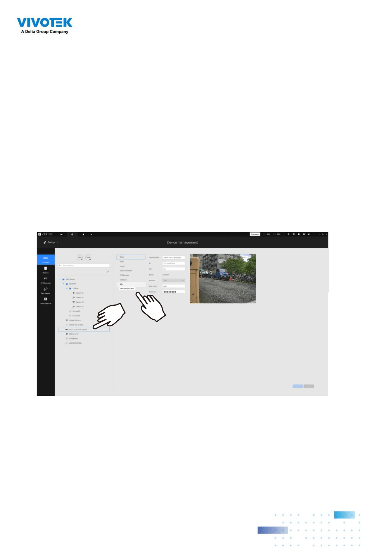
220220
Appendix G: Using LPR
Related Functions w/ Data
Magnet
Acquiring data sources from 3rd-party software:
1. Select a camera that comes with the LPR (License Plate Recognition) functionality, e.g.,
IB9387-LPR as shown below. Click "More settings on Web" to open a web console to the
camera.
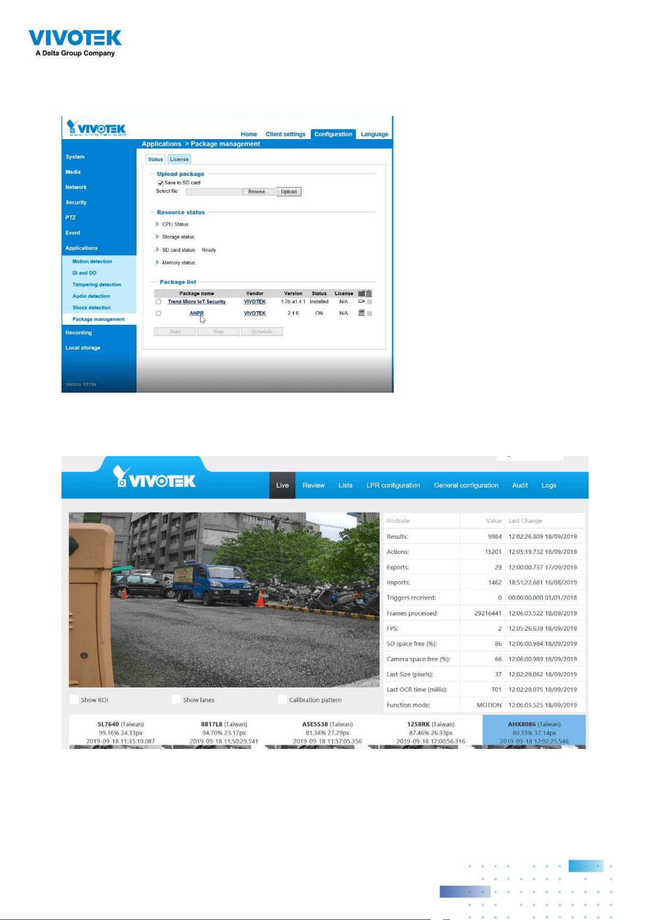
221221
2. On the web console, enter Configuration > Applications > Package management. Click
on ANPR to open a web console to the license plate recognition software.
3. Click on the Lists tab.
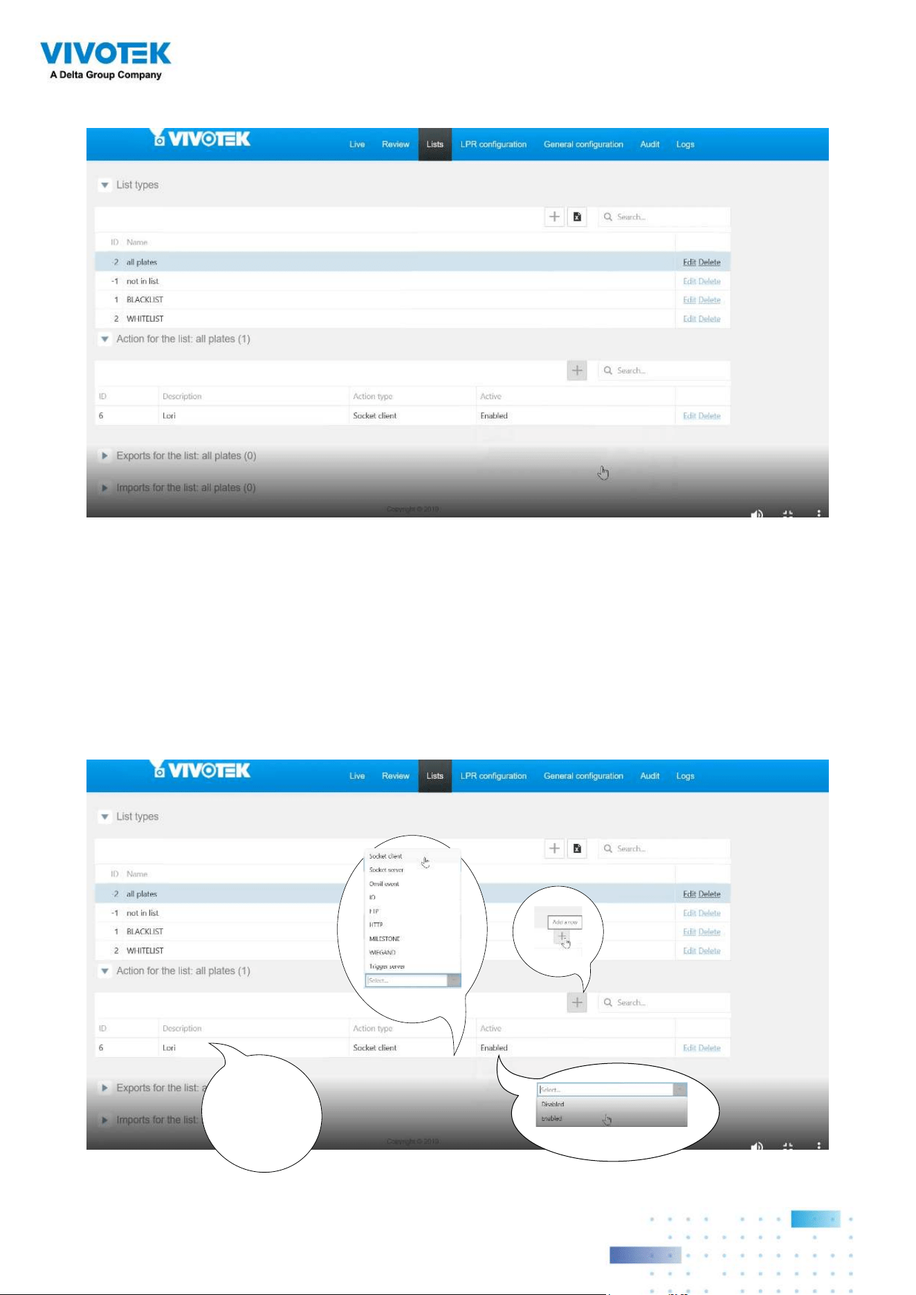
222222
4. Select a list whose data will be transmitted to the VSS server.
5. 5-1. Find the "Action for the list" pane. Click the "+" Add a row button.
5-2. Enter a short description for the row.
5-3. Select "Socket client" as the action type.
5-4. Click to select Enabled.
5-5. Click the Save button.
1
2
enter a
short description
3
4
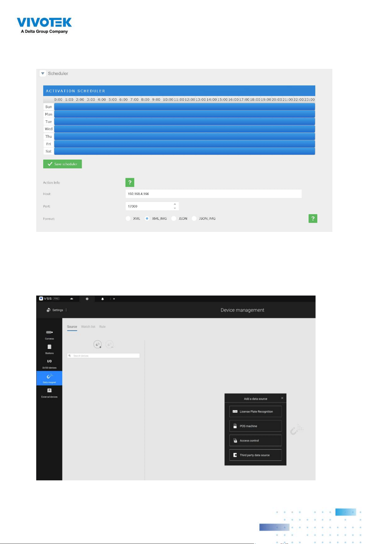
223223
6. Roll down to enter your VSS server's IP address. If necessary, select XML_IMG as the file
format for your data that will be collected on VSS.
7. Close the web console and return to the VSS Settings > Device management > Data
magnet page.
Click the Add button, and click the License Plate Recognition button.
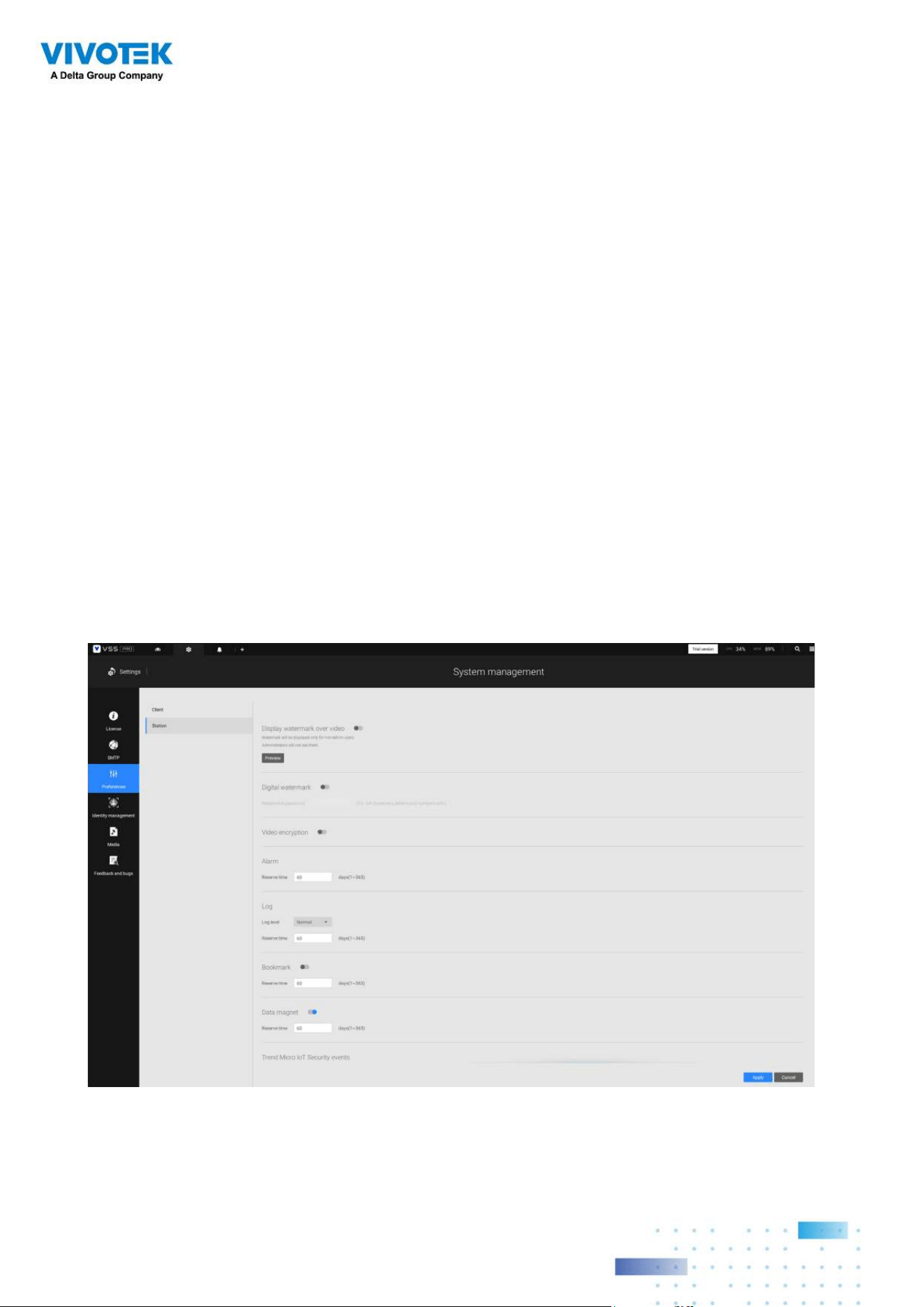
224224
If you need the development document for integrating 3rd-party software, please contact
VIVOTEK's technical support.
You can designate how many days the data from the data sources is retained on server
in Settings > System management > Preferences.
NOTE
:
1. The VSS server port for License Plate Recognition data source can be customized; It is
not limited to 17000.
2. If you have more than one VIVOTEK LPR camera, you only need to (and can only) add a
License Plate Recognition data source.
3. If you add a 3rd-party data source but you name it as "VIVOTEK ANPR", it will be
recognized as a VIVOTEK ANPR (License Plate Recognition) data source.
4. Different Data sources cannot have the same name.
5. Different 3rd-party data sources can share the same server port, but they cannot use the
same port the License Plate Recognition is using.
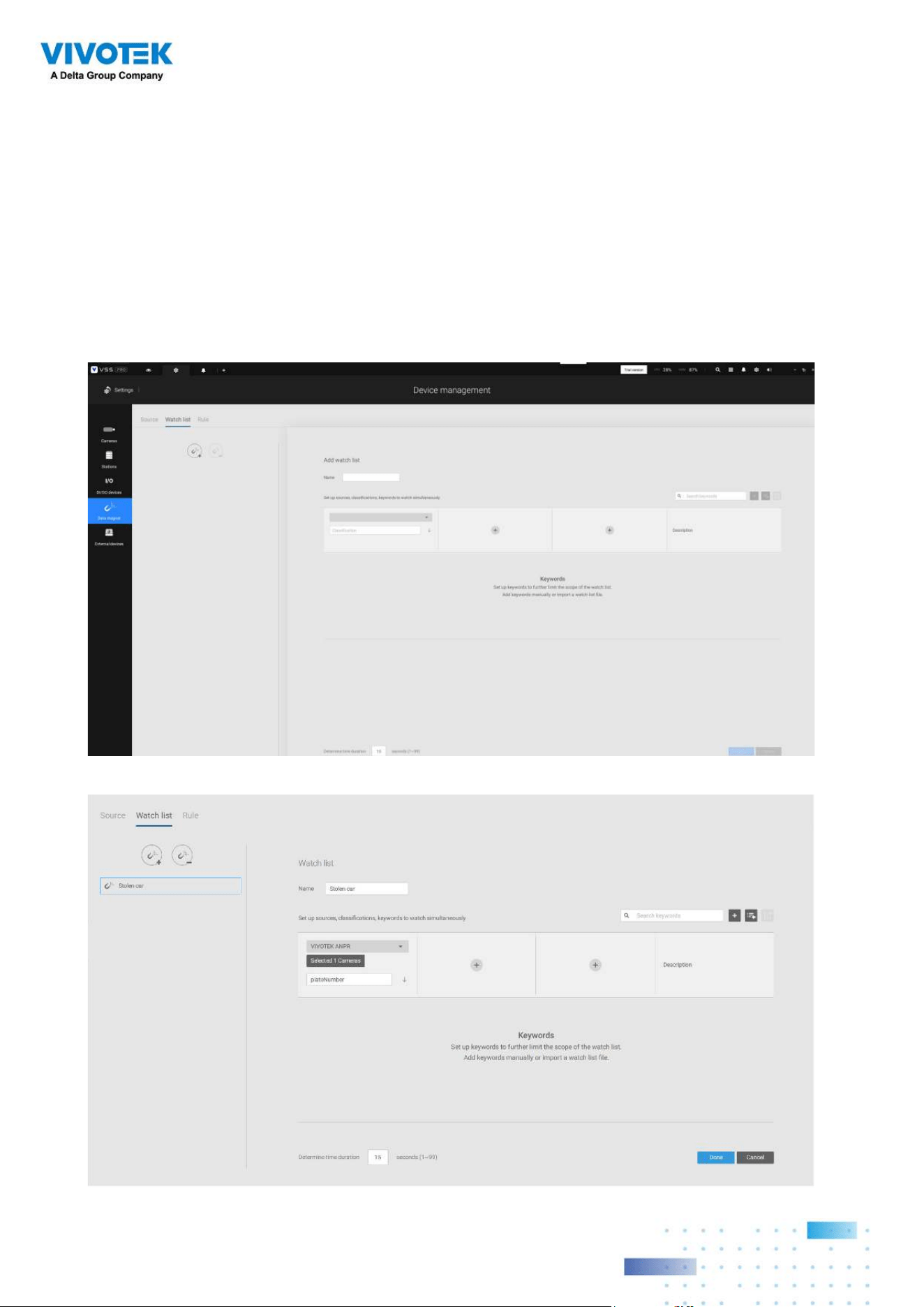
225225
Configuring a Black or White list:
With a license plate application, you can configure either a Black list for suspicious plate
numers, such as those for unwelcome or stolen cars, or a White list for VIP customers or
the employees of your facility.
1. Click and select Watch list in the Data Magnet window. Click the Add button, and enter a
name, e.g., Stolen car. Select "VIVOTEK ANPR" and camera as a data source, and enter a
classification for the referential parameter in your Data Magnet json, e.g., PlateNumber.
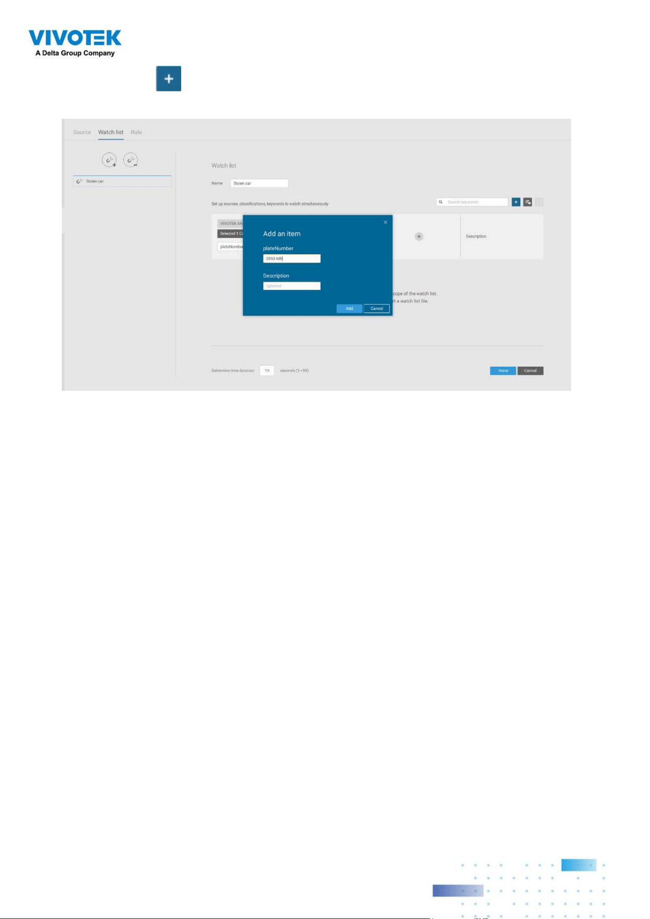
226226
2. Click the Add
button and enter a plate number such as one for a stolen car. Click
Add to finish, and repeat the process for more items.
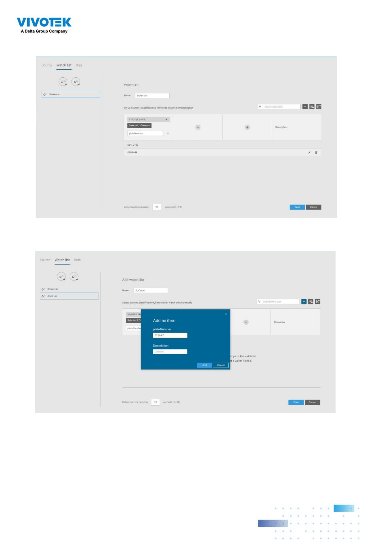
227227
3. The added items will be listed. When done, click the Done button below.
4. Using the same method, you can create a White list for some plate numbers to gain
access, such as VIP customers.
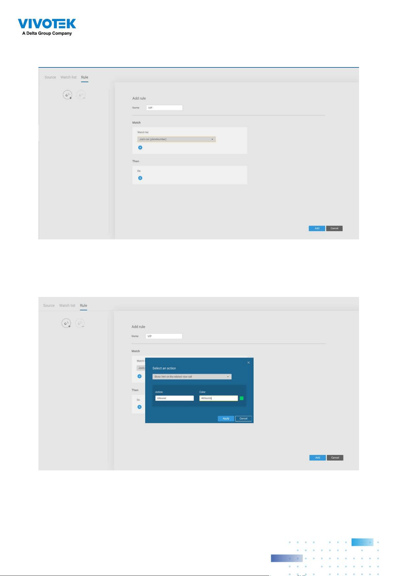
228228
5. Click on the Rule tab. Click the Add rule button then enter a name for the rule. Select a
Watch list you previously configured.
6. Select an action such as Show hint on the related view cell.
Enter a word you want to show on the related view cell. Enter hex color code for the word
displayed on view cell. Click Add to finish the configuration.
.
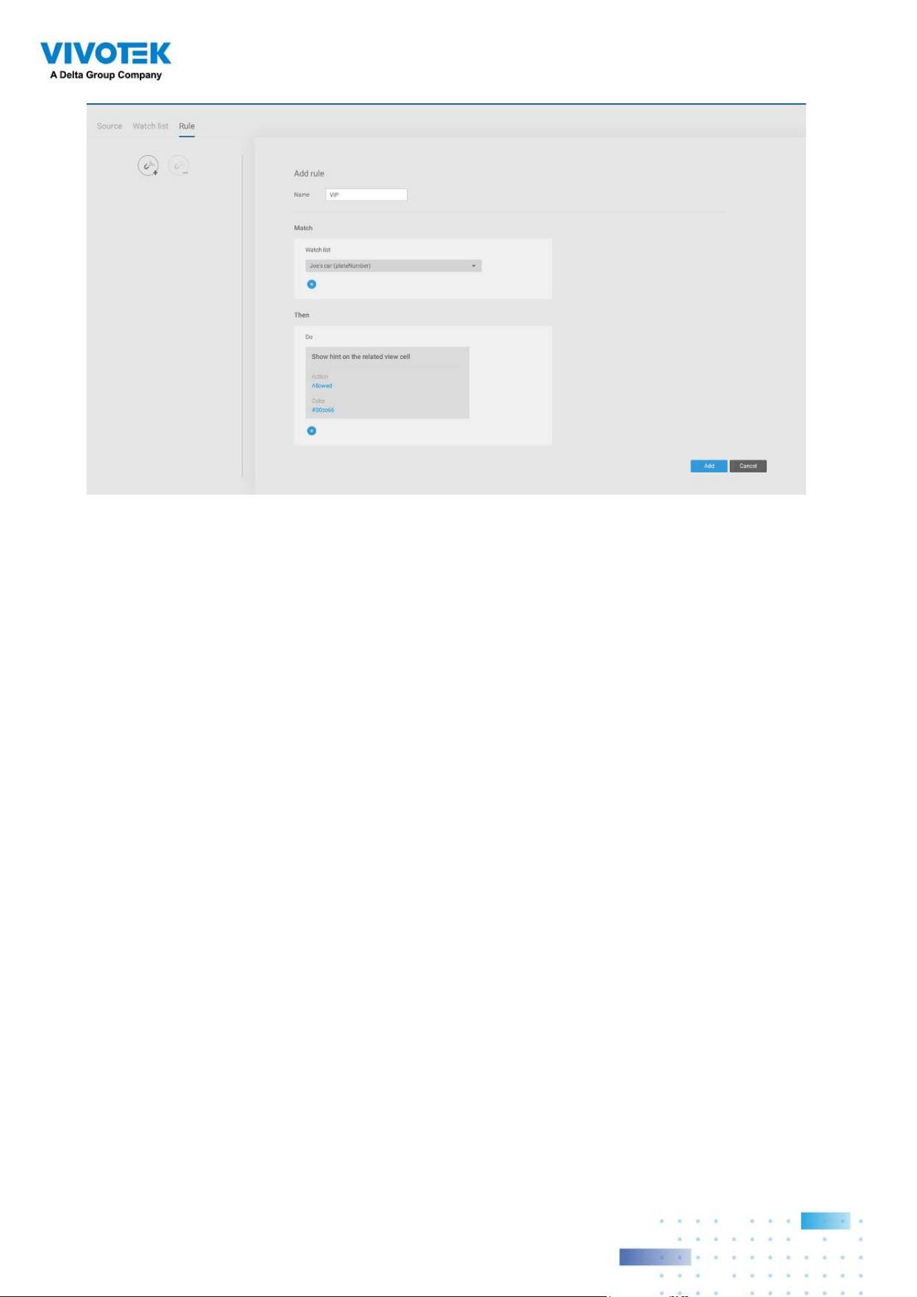
229229
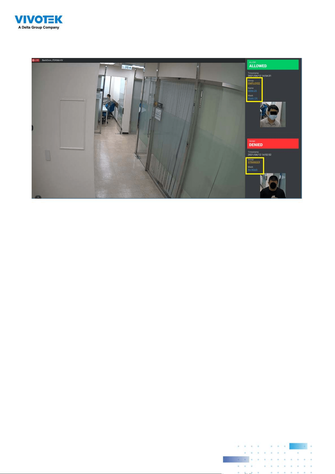
230230
7. On the VSS view cell, the ALLOWED or DENIED rule message will display along with your
watch list and other information.
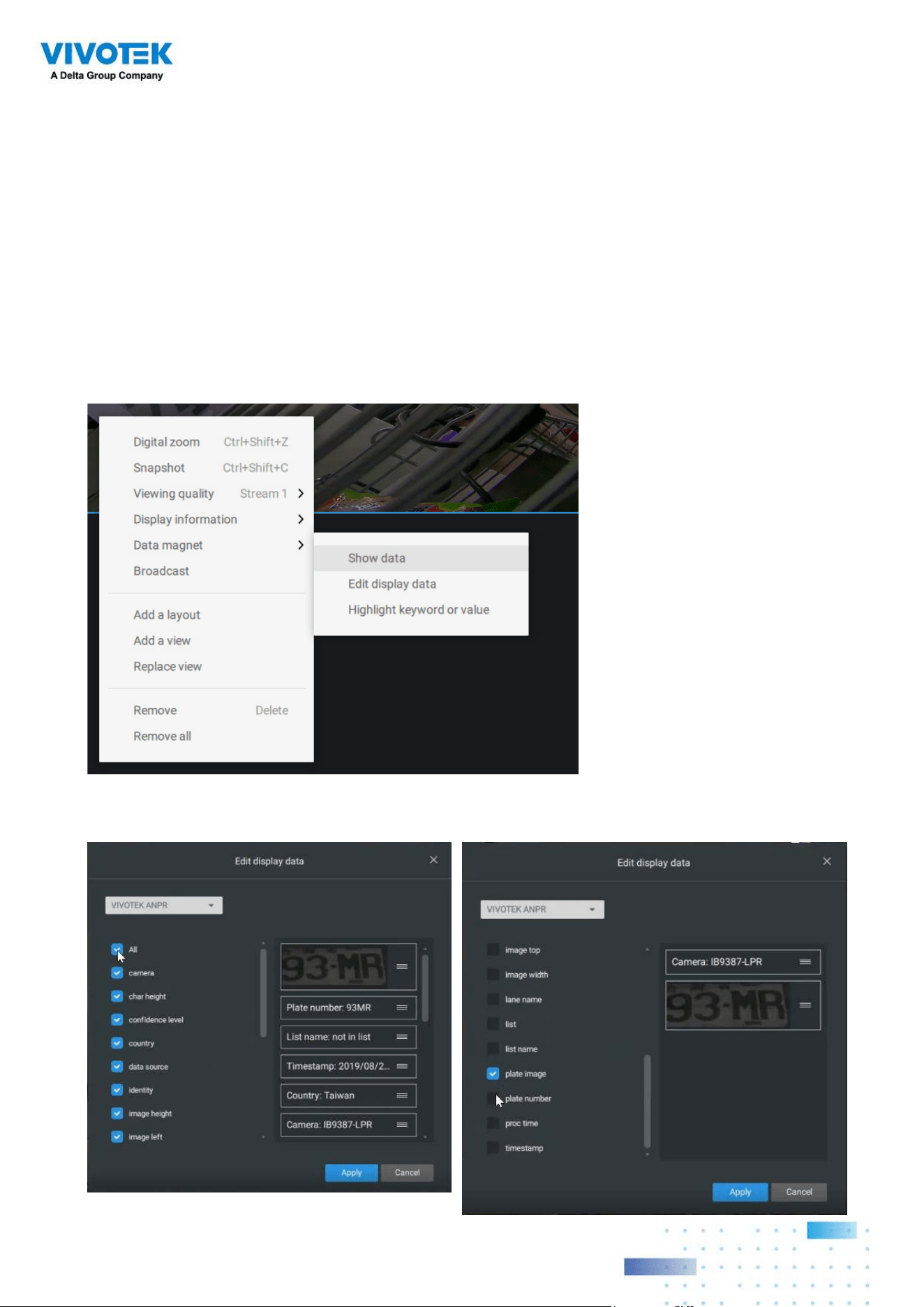
231231
Selecting data display options:
1. On the VSS live view, right-click on screen to display Data Magnet > Edit display data.
If Show data is selected, a portion of the view cell will be used to display the captured
data.
2. On the Edit pane, select all or manually select multiple display elements.
There are two different ways to show data:
1. Right-click: Data Magnet > Show data.
2. Right-click: Display information > Edit display information > Data magnet data.
The display options are: with or without Data overlay on screen. If the overlay is not
enabled, the data will display on the right pane of the view cell.
The data on the overlay can
be configured to automatically
disappear after a configurable
time, when no new data is
received (Hide data after idle _
s).
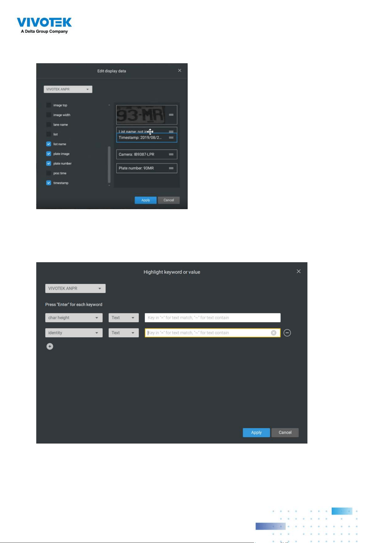
232232
3. Click and drag individual elements to change their top-down positions on the screen.
When done, click the Apply button.
4. Click Highlight keyword or value. You can display information of unusual data, such as
the specific numbers or characters of forbidden license plates. When such data is met,
the occurrence will be highlighted in a bright yellow color.
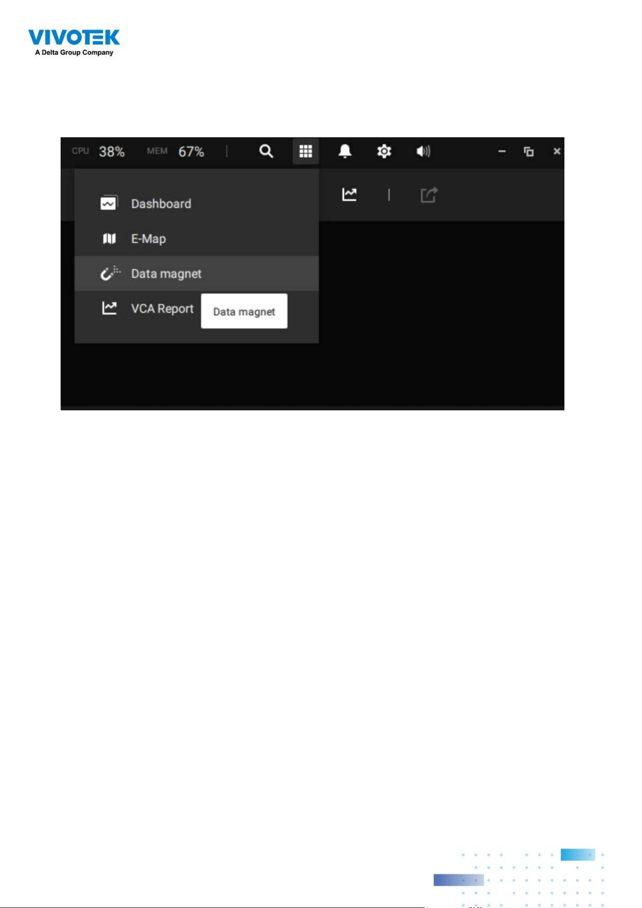
233233
Searching for data and linked recordings:
1. On the VSS live view, click on the Applications tab.
234234
2. On the Data Magnet window, select the LPR camera, and then begin with configuring the
search conditions. Select the time span from the calendar. Select to display character
height, country, data source, identity, image height, lane name, list name, or enter a plate
number. You can select multiple filtering conditions.
3. Click the Search button. The search results will display. Single-click to display the related
video. You can also review the video in a full-screen mode.
You can click and drag the display names of individual columns to switch their positions
on the screen. The changes to layout are stored on the client computer. After you re-
arrange the order of columns in search results, the display order will also be applied to
the exported CSV file.
4. You can select and export a license plate capture using the Export function. Click on the
export button. A folder button will display. Click on it to access the exported file.
The target directory will open. Open the exported CSV file to view the search results.
You can also open a chart view by clicking the
Chart view button. The chart view
can also be exported as a png file.
An evidence image will be available with the search result along with the plate picture.

235235
Configuring Data Magnet alarms:
1. Enter Settings > Alarm > Add & Delete to create a new alarm setting. Click to select
External devices.
2. Select VIVOTEK ANPR as your triggering source. Select and create triggering conditions
such as character height, image width, list, list name, country, etc. Use "=" for text
matching, "~" for text containing, or approximately matching specific characters, and
also ">," "<," ">=," "<=" for numbers larger or smaller than a preset value.
3. Continue to configure your triggering conditions. You can create multiple conditions.
4. Continue to configure the actions for a triggered alarm, such as sending live streaming.
5. When done, enter a name for the alarm and click the Add button to complete.
6. You can now receive alarm notifications triggered by license plate recognition via the
Data Magnet.
Note that if you select "Include event-triggering camera" during the alarm configuration
stage, the camera delivering the data source will be automatically selected.
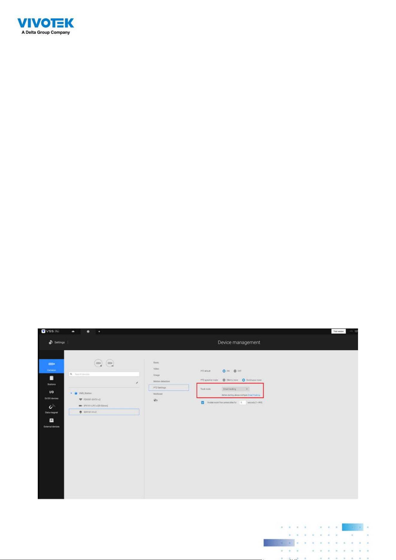
236236
Appendix H: Enable Smart
Tracking for Speed Dome
Cameras
The Smart tracking function is available on speed dome cameras, such as SD9374-EHLX.
The Smart tracking feature is separately configured on the camera side. Please refer to
Smart Tracking User Guide for configuration details.
To display Smart tracking on VSS,
1. Enter Settings > Devices > Cameras.
2. Select the speed dome camera that supports this feature.
3. Select PTZ Settings, and the Track mode menu. Select Smart tracking as the tracking
display mode. A hyperlink is provided for the Smart tracking configuration page.
It is recommended to always enable "
Enable track if the camera idles for xx seconds."
Manual PTZ control always has a higher priority and will interrupt tracking.
4. Click the Apply button.
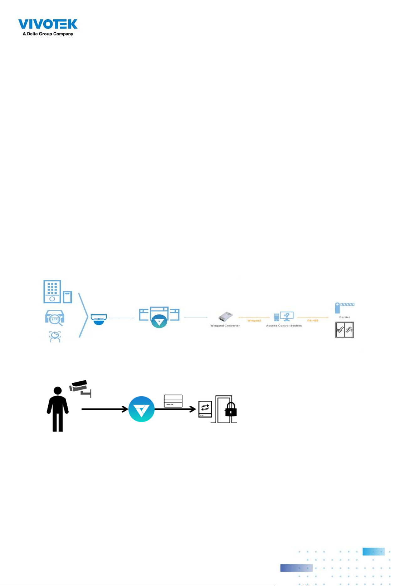
237237
Appendix I: Multi-factor
Authentication for Access
Control
Via multiple data magnet sources, access authentication can be achieved for the following:
1. License plate recognition system, Face recognition system, 3. Access control system.
For example, in a parking lot, if someone wants to leave, the LPR system at the gate will
recognize the license plate, and the face recognition will verify the driver's identity. If both
recognition succeed, the gate will open allowing the driver to leave.
In an office, an access control system can be combined with Face recognition mechanism
to avoid someone using someone else' card to cheat the attendance system.
The scenario shows one holds an ID card and via the Face recognition system, his identity
is verified as one employee in the database. VSS then acquires his ID card serial no.,
passes it on to an Wiegand converter. The Wiegand converter then passes it to the access
control. In addition to the original ID card access control, multiple utilities can be combined
into the access control mechanism.
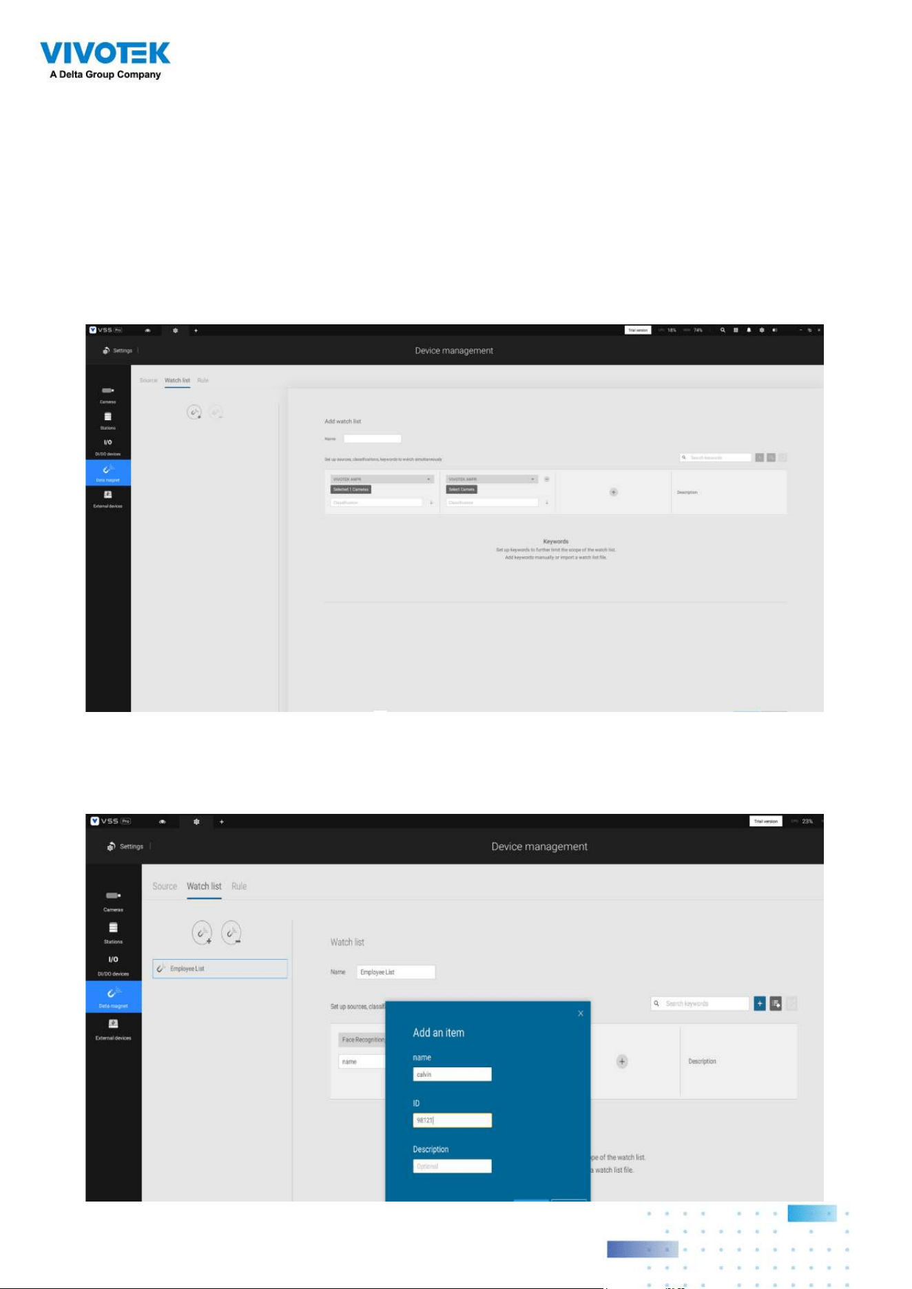
238238
To acquire data from multi-factor systems, we use the Watch list on Data Magnet.
1. Depending on your applications, configure mutiple data magnet sources, so that data
can be transferred and acquired by VSS.
2. Click and select Watch list in the Data Magnet window. Click the Add watch list button,
and enter a name, e.g., Employee list. Select 2 or 3 pre-configured data sources, and
enter the classification you would like to watch for the referential parameter in your Data
Magnet json, e.g., name, ID.
3. Click the Add item button and enter a name and employee ID such as one for an
employee. Click Add to finish, and repeat the process for more items.
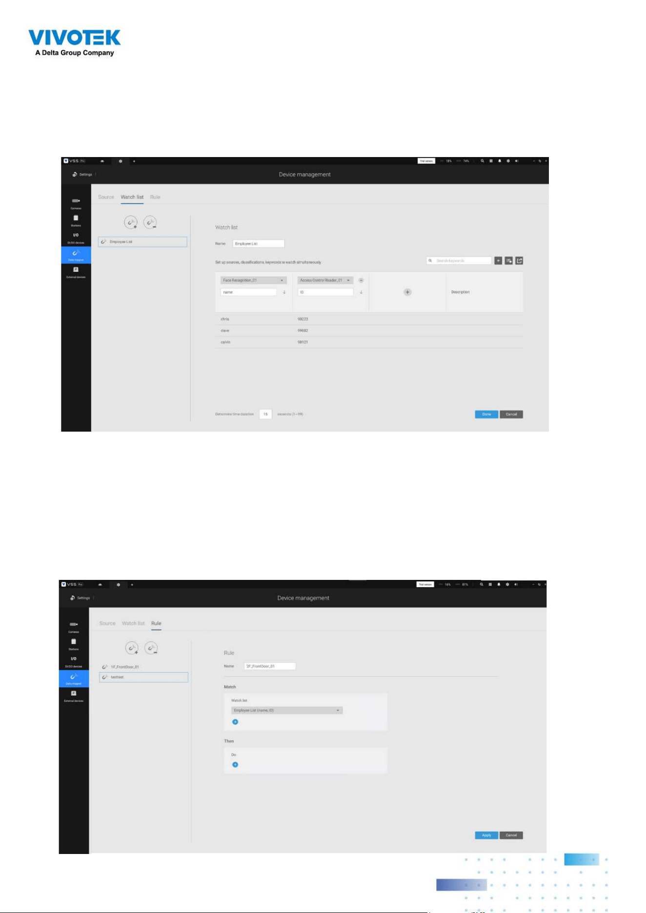
239239
4. At the lower screen, enter the time threshold for receiving data from multiple sources.
For example, If set to 15 seconds, VSS will need to receive within this time the facial
recognition and the card ID no. from the access control reader. Both data will be verified
and checked against the data on the watch list, e.g., name=Chris, ID=90223.
5. Click on the Rule tab. Click the Add rule button, and then enter a name for the rule. In
the Match block, select a Watch list you previously configured. In the Then field, you can
configure your rule action. There are 2 actions available:
1. Show hint on the related view cell. 2. Select data to send to Wiegand converter.
If you apply your rule to be an alarm management trigger, you can bypass the Then
action settings.
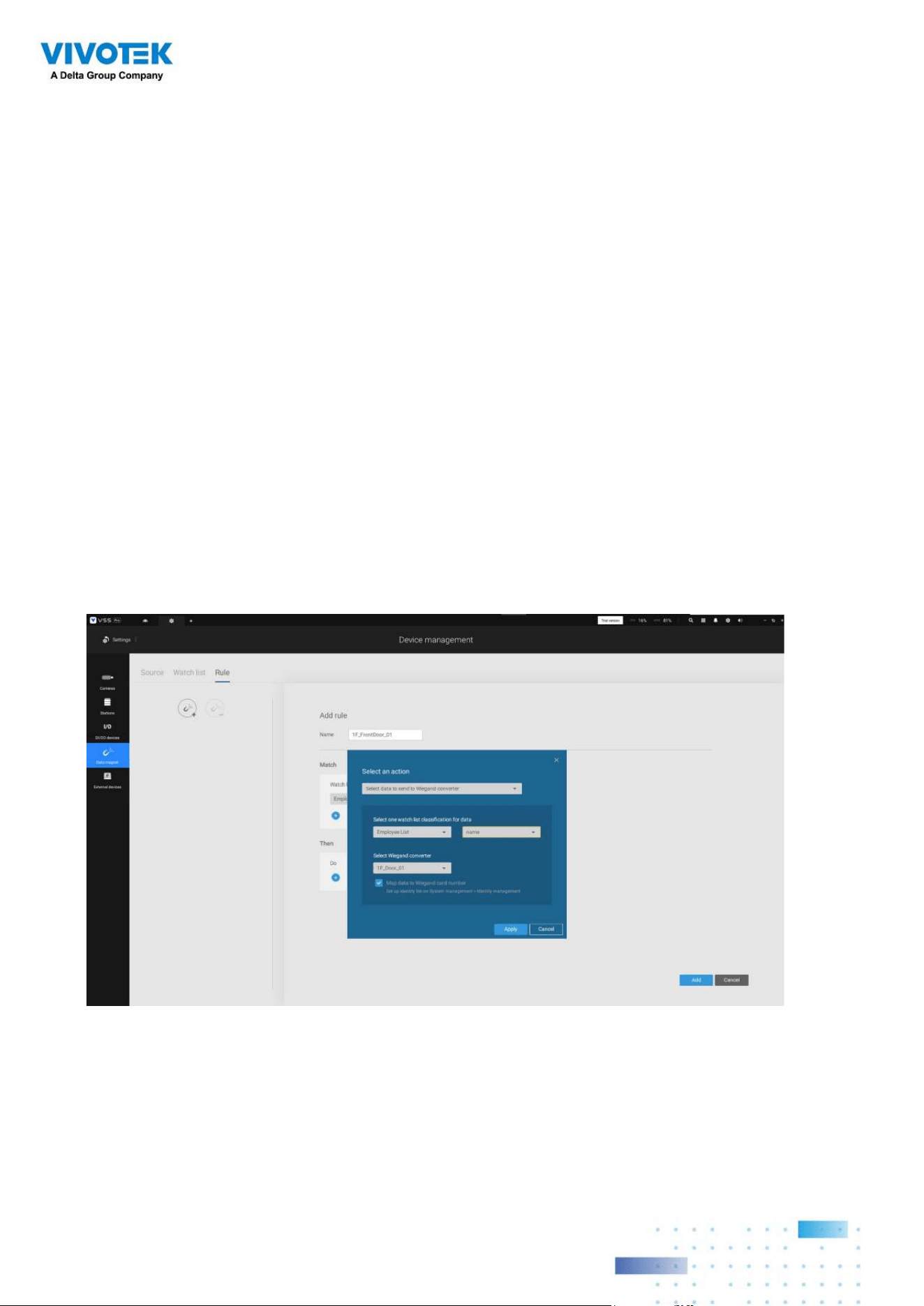
240240
How to configure "Select data to send to Wiegand converter?"
VSS has incorporated the support for Wiegand converter AO-20W (https://www.vivotek.
com/AO-20W)
The Wiegand converter can transfer the ID Badge card number through the Wiegand
protocol to an access control system. The access control system then decides whether
to open a gate or not. The VSS station sends an employee's card number to the Wiegand
converter, the Wiegand converter then delivers it to an access control system.
To Select data to send to Wiegand converter, first select a watch list classification, and
then select a Wiegand converter.
For example, a watch list's employee name=Chris and ID=90223 is verified, you can send
the ID card umber to the Wiegand converter. If a watch list's data is not the card number,
but the data contains name=Chris, employee ID=90223, you can select "Map data to
Wiegand card number." Via the Identity management process, the identity data (such as
name) is transferred into a corresponding ID Badge Wiegand card number, and then is
sent to a Wiegand converter.
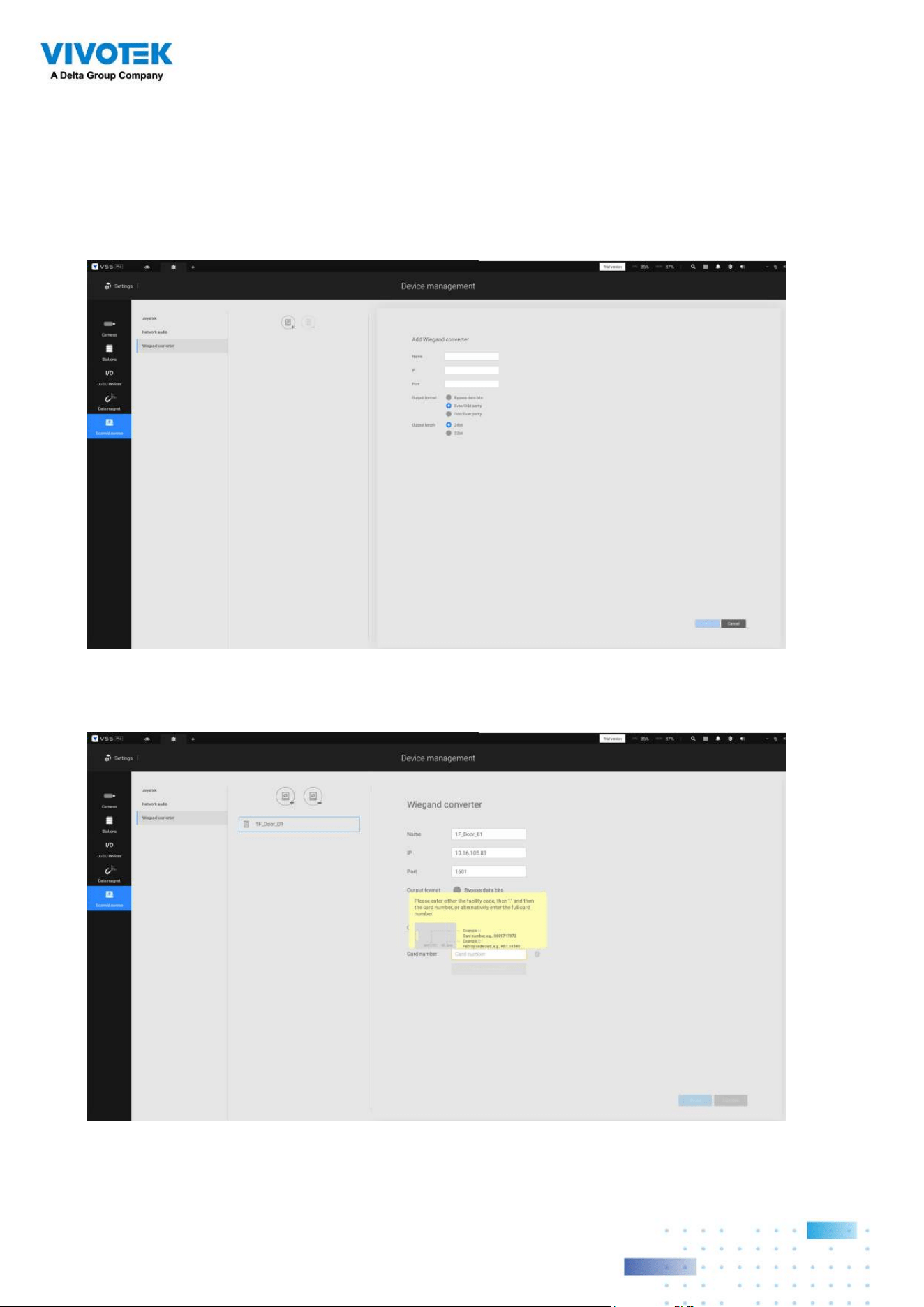
241241
How to add a Wiegand converter to VSS?"
In Settings > External devices > Wiegand Converter, click the add Wiegand converter
button. Enter the converter's IP, Port, Output format, and Output length. You can acquire
the converter's data via a web console to it.
When adding is completed, enter a card number in the Card number field to test if the
converter can successfully receive a card number.
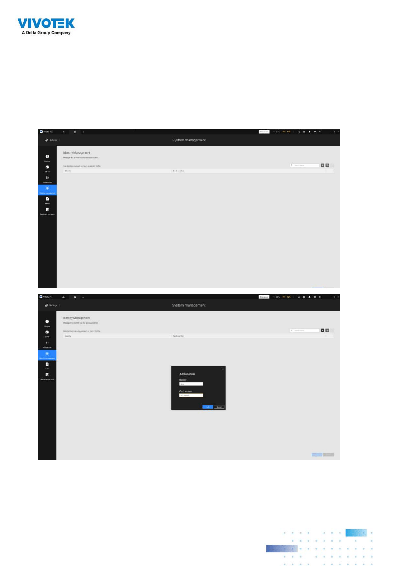
242242
How to configure Identity management?"
In Settings > System > Identity Management, click the add an item button and enter the
identity and card number.
Identity is the information such as name or employee ID or car license plate. The Card
number is the ID Badge's Wiegand card number.
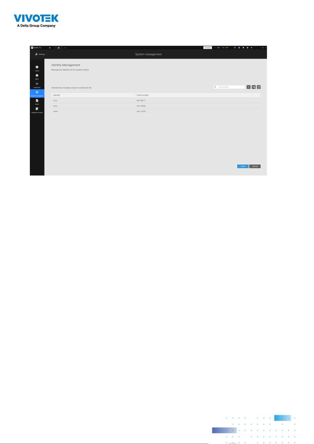
243243
An identity table should look like this.

