
MILWAUKEE ELECTRIC TOOL CORPORATION
13135 W. Lisbon Road, Brookeld, WI 53005
Drwg. 2
FIG. PART NO. DESCRIPTION OF PART NO. REQ.
44 05-83-0020 M4 x 0.7 Pan Hd. Taptite Screw (2)
52 05-88-1200 M4 x 16 Pan Hd. Plastite T-20 Screw (2)
59 31-17-0080 Cord Clamp (1)
68 06-82-0009 M5 Pan Hd. T-25 Screw (4)
69 06-82-0011 M4 Pan Hd. T-20 Screw (7)
70 --------------- Housing Cover (1)
71 43-12-0055 Handle Square Driver (1)
74 45-88-0028 Washer (2)
75 40-50-0029 Disc Spring (3)
76 --------------- Magstand Base with Bushings (1)
79 --------------- Housing Support (1)
80 05-81-1290 M2.3 x 0.4-6g Washer Hd. T-8 Screw (2)
82 05-74-0014 M8 x 1.125, 6mm Hex Socket Hd. Cap Scr. (2)
84 43-62-0017 Carrying Handle (1)
85 22-64-0012 120V Power Cord Assembly (1)
88 43-62-0022 Feed Handle (3)
89 31-17-0085 Cord Clamp (1)
90 06-83-0015 2mm Hex Set Screw (3)
92 23-66-0017 LED Switch Assembly (1)
94 22-09-0042 Lower Control Board with LED (1)
95 --------------- Dovetail Rail (2)
96 44-80-0061 Rack (1)
97 --------------- Slide (1)
98 06-75-3050 1/4-20 x 3/4", 3/16" Hex Socket Hd. Screw (3)
102 44-60-0002 Alignment Pin (1)
109 --------------- Insert Adapter (1)
110 --------------- 8-32 Screw (4)
128 45-88-0039 Rubber Washer (1)
See pages 4 and 5
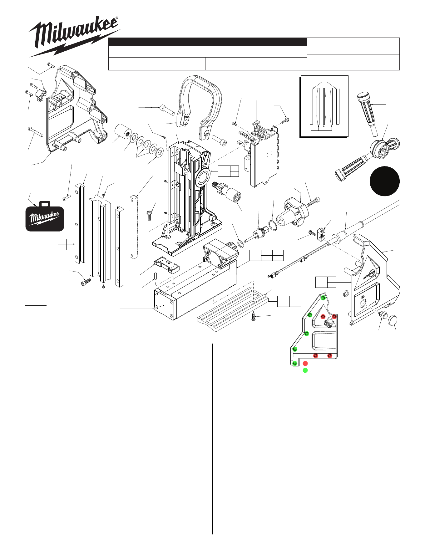
4274-20
54-46-0440
G85A
120V Permanent Magnet Drill
REVISED BULLETIN
DATE
SERVICE PARTS LIST
BULLETIN NO.
WIRING INSTRUCTION
CATALOG NO.
SPECIFY CATALOG NO. AND SERIAL NO. WHEN ORDERING PARTS
STARTING
SERIAL NUMBER
Apr. 2018
Torque
Chart on
Page 6
74
75
Position #75 Disc
Springs as shown
69(5x)
59
52(2x)
68(4x)
70
71
74
75
74
142
(6x)
95
(2x)
97
147
(2x)
96
82
(2x)
90
(3x)
84
76
141
(4x)
98
(2x)
94
102
88
(3x)
160
80
(2x)
175
44
(2x)
159
128
129
130
132
98
89
85
69
(2x)
92 138
79
109
110
(4x)
161
109
110
158
95
97
176
70
79
135
128 129
130
174
177
76
90
DO NOT disassemble Magnetic Base (174)
beyond items 128, 129 & 130. Internal
components beyond that point are timing sensitive.
FIG. PART NO. DESCRIPTION OF PART NO. REQ.
129 45-08-0018 Spindle Lock Shaft (1)
130 34-40-0029 Retaining Ring (1)
132 43-98-0044 Magnet Control Knob (1)
135 42-55-0130 Blow Molded Carrying Case (1)
138 22-68-0020 Switch Cover (1)
141 05-81-2787 1/4-20 x 1", 4.5mm Hex Button Hd. Screw (4)
142 05-74-0013 3mm Hex Socket Head Cap Screw (6)
146 45-56-0017 Safety Strap (Not Shown) (1)
147 05-80-2787 M3 Flat Head Machine Screw (2)
158 44-81-0070 Dovetail and Rail Kit (1)
159 36-18-0030 Rack/Gear Shaft Assembly (1)
160 43-78-0032 Quick Connect Hub Assembly (1)
161 48-10-0130 Pipe Adapter Insert Kit (Accessory) (1)
174 42-20-2787 Magnetic Base/Rear Gearcase Assembly (1)
175 22-09-0100 PCBA/Electronics Assembly (1)
176 43-76-4274 Housing Assembly (1)
177 42-20-0025 Support Housing (1)
10-20-0496 Danger Label (1)
12-20-4274 Service Nameplate (Not Shown) (1)
49-96-0035 Hex Key (Not Shown) (1)
= (68) 06-82-0009
= (69) 06-82-0011
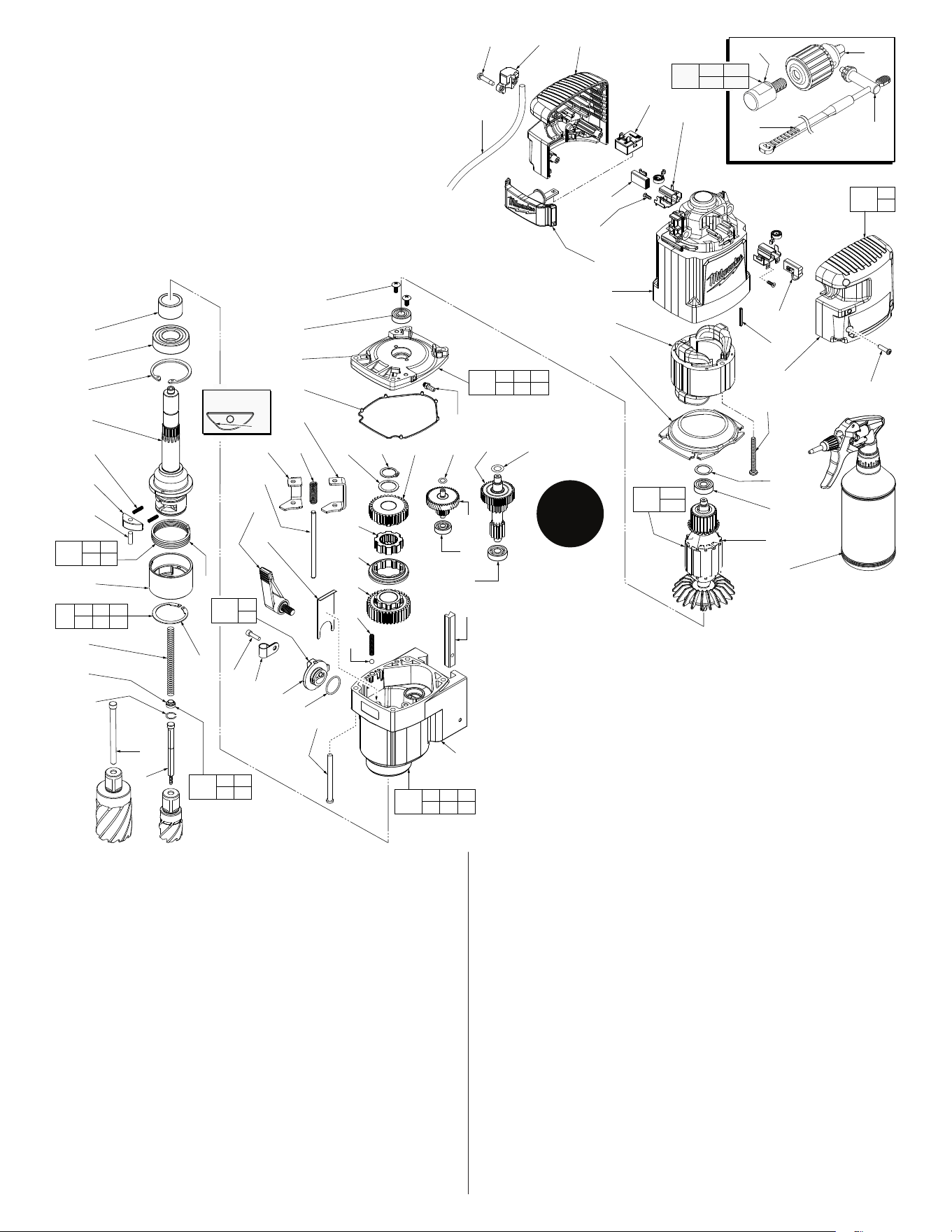
FIG. PART NO. DESCRIPTION OF PART NO. REQ.
1 44-60-0433 Telescoping Pin for 2" Cutters (1)
2 44-60-0007 Ejector Pin Assembly (1)
3 48-66-0025 Chuck Collar (1)
3a 34-60-0003 Retainer (1)
3b 42-76-0017 Spindle Collar (1)
3c 40-50-0336 Torsion Spring (1)
3d 40-50-0097 Spring (2)
3e 43-96-0015 Spindle Key (1)
3f 32-75-0018 Spindle with Pin (1)
3g 44-60-0004 Pin (1)
4 --------------- Spindle Plug (1)
5 --------------- Spring (1)
6 34-60-0007 Retaining Ring (1)
7 02-04-0011 Ball Bearing (1)
8 06-82-7455 8-16 x 2.38 Pan Hd. Plastite T-20 Screw (4)
9 05-81-1410 M4 x 16 Pan Hd. T-20 Screw (1)
10 31-17-0030 Cord Clamp (1)
11 44-10-0016 Adjustment Lever Assembly (1)
FIG. PART NO. DESCRIPTION OF PART NO. REQ.
12 --------------- Speed Knob (1)
13 34-40-1570 O-Ring (1)
14 44-90-0006 Shift Knob Retainer (1)
15 44-94-0017 Guide Rod (1)
16 42-36-0011 Shift Bracket 'B' (1)
17 40-50-0023 Shift Spring (1)
18 42-36-0018 Shift Bracket 'A' (1)
19 --------------- Gear Case with Pin (1)
20 44-20-0021 Dovetail Lock Block (1)
22 02-02-0103 Steel Ball (1)
23 40-50-0038 Detent Spring (1)
24 02-04-0640 Ball Bearing (1)
28 32-40-0115 3rd Intermediate Gear, Low (1)
29 43-12-0065 Drive Hub (1)
30 42-90-0015 Coupler (1)
31 32-40-0130 3rd Intermediate Gear, High (1)
32 45-88-3140 Washer (1)
33 34-60-0009 Retaining Ring (1)
36 02-04-0820 Ball Bearing (1)
40 43-44-0031 Gasket (1)
41 --------------- Diaphragm (1)
42 43-33-0025 Lube Hose Fitting with O-Ring (1)
43 02-04-0620 Ball Bearing (2)
44 05-83-0020 M4 x 0.7 Round Head Phillips Screw (2)
46 06-81-5383 M4 x 35mm Pan Hd. Plast. T-20 Screw (4)
47 --------------- Motor Housing Cover (1)
FIG. PART NO. DESCRIPTION OF PART NO. REQ.
48 05-81-0100 M3-24 x 10 Pan Hd. ST Phillips Screw (4)
49 22-18-0215 120V Carbon Brush with Cut-O (1)
50 22-20-0135 Brush Holder Assembly with Spring (2)
51 23-66-0635 On/O Switch (1)
52 05-88-1200 M4-18 x 1.4 Pan Hd. ST T-20 Screw (2)
53 23-94-0560 Terminal Contact Wire Assy. (See Wiring) (1)
56 31-50-0615 Motor Housing (1)
57 22-18-0225 120V Carbon Brush without Cut-O (1)
58 --------------- Motor Housing Support (1)
59 31-17-0035 Cord Clamp (1)
60 44-60-0381 Ground Pin (1)
61a 18-01-0120 Field Assembly (1)
61b --------------- Armature (1)
62 06-82-7425 8-16 x 2" Slt. Pan Hd. Plastite T-20 Screw (2)
63 45-88-0031 Wave Washer (1)
64 42-14-0045 Fan Bae (1)
65 44-90-0012 Retainer (1)
66 42-40-0101 Bushing (1)
67 23-94-0032 120V Connection Cord (1)
133 48-66-1355 Chuck (1)
134 48-66-3280 Chuck Key (1)
143 48-66-4040 Chuck Key Holder (1)
144 --------------- Chuck Adapter (1)
145 42-51-0100 Lubricant Bottle (1)
150 45-88-0621 Washer (1)
151 45-88-0631 Washer (1)
152 14-46-2787 Ejector Spring Kit (1)
153 43-98-0071 Speed Knob Assembly (1)
154 43-96-0091 Spring/Key Kit (1)
155 14-29-0135 Pinion/2nd Intermediate Gear Assembly (1)
156 14-29-0115 Pinion/1st Intermediate Gear Assembly (1)
157 14-13-0040 Diaphragm Assembly w/ Bearings and Seal (1)
170 42-42-0625 Switch Button Assembly (1)
171 16-01-0120 Armature Assembly (1)
172 14-30-0165 Gear Case Assembly (1)
173 31-44-1265 Housing Support/Cover Assembly (1)
191 49-59-0020 3/4" Weldon to 1/2" Chuck Adapter w/ Key (1)
Torque
Chart on
Page 6
144
133
143
134
40 41 42
43 44
157
52(2x) 59 58
51
67
57
48(4x)
170
56
61a
64
50(2x)
49
60
47
62(2x)
63
43
61b
145
46(4x)
66
7
6
3f
3d
3e
3g
3b
5
4
65
1
2
3c
44(2x)
43
41
40
16
17
32 33 31 150 155 151
18
15
11
14
42
29
30
28
23
22
156
24
36
20
9
10
12
13
8(4x)
19
4 5
65
152
3c 3d
3e 3g
154
3a 3b 3c
3d 3e
3
153
12
13
6 7 19
24 36
172
171
43
61b
173
47
58
3a
133 134
144
191
Orientation of
3e is important
Flat
NOTE: #11 is
located on the opposite
side of gearcase than shown.
SERVICE FIXTURES:
61-30-2787
Rotor Press Fixture
61-30-2788
Spindle Bushing Press
Fixture
61-30-2789
Rotor Removal Fixture
LUBRICATION:
Type "Y" Grease, No. 49-08-5270 (6 oz. tube)
Use approximately 85 grams, 3 ounces
LUBRICATION NOTE: When servicing the drill
motor, 90-95% of old grease must be removed
prior to new grease being added.
17 16
18
15
14
12
13
151
155
19
32
6 7 19
24 36
172
29
30
28
23
22
31
33
66
3f
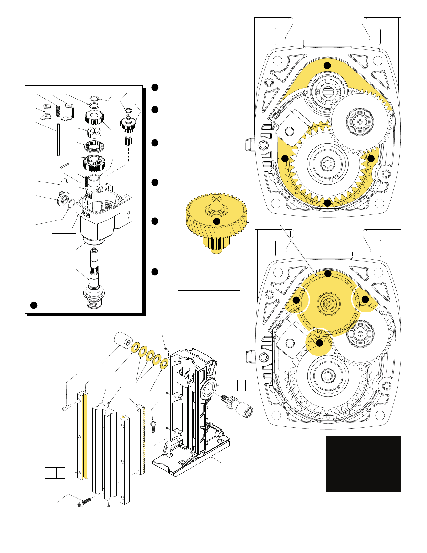
Install parts shown into/onto
Gear Case Assembly (172)
prior to applying any lubrication.
Apply 13 grams (approximately
.45 ounces) of grease in this
area of the gear case prior to
installing the Pinion/1st Inter-
mediate Gear Assembly (156).
With the aid of a grease gun,
place 26 grams (approximately
.9 ounces) in and around the
gear case cavity for the 3rd
Intermediate Gear system (28,
29, 30 and 31).
Apply a heavy coating of grease
over the entire Pinion/1st Inter-
mediate Gear
Assembly
(156).
Install the
assembly
(156) into
gear case and
place 5-8 grams
(.17-.28 ounces)
fully around gear
space.
This step will require 39 grams (1.4
ounces) of grease. Place 13 grams
(approximately .45 ounces) of
grease at each of three positions
over and around the Pinion/1st
Intermediate Gear Assembly (156).
1
2
3
4
5
1
2
3 3
3
4
5
6
6
6
6
156
90(3x)
71
74
147
(2x)
75
74
141
(4x)
142
(6x)
95
(2x)
97
96
76
158
95
97
76
90
177
Lightly coat the inside ‘V’ channel of both
Dovetail Rails (95) with grease.
Place a light coat of grease onto the front
teeth of the Rack (96).
Lightly coat both sides of the two Washers
(74) and three Disc Springs (75).
This bottom screw
(98) must be loosened
3 to 4 turns in order to
remove the Slide (97)
and the Rack (96).
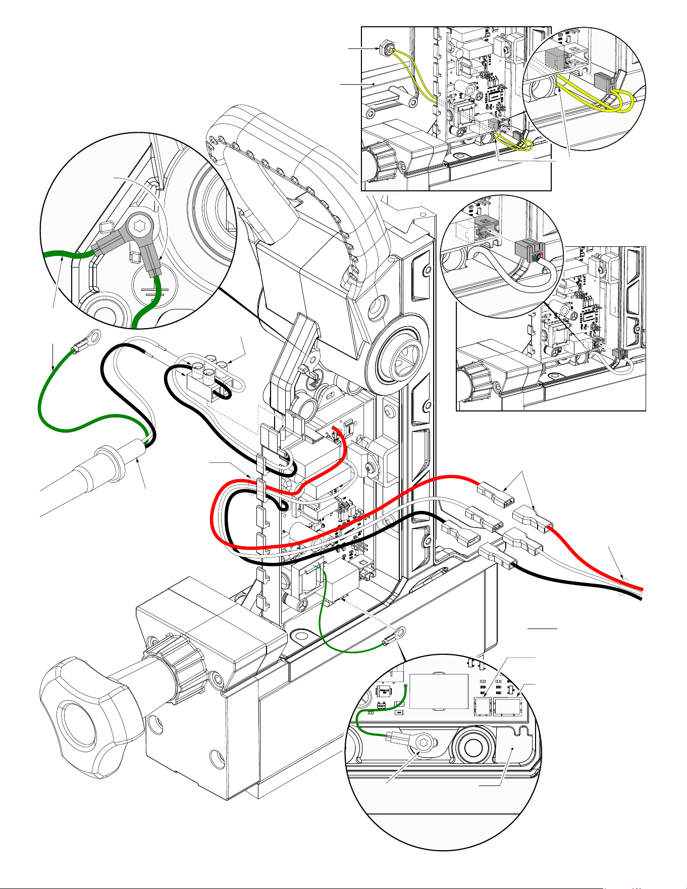
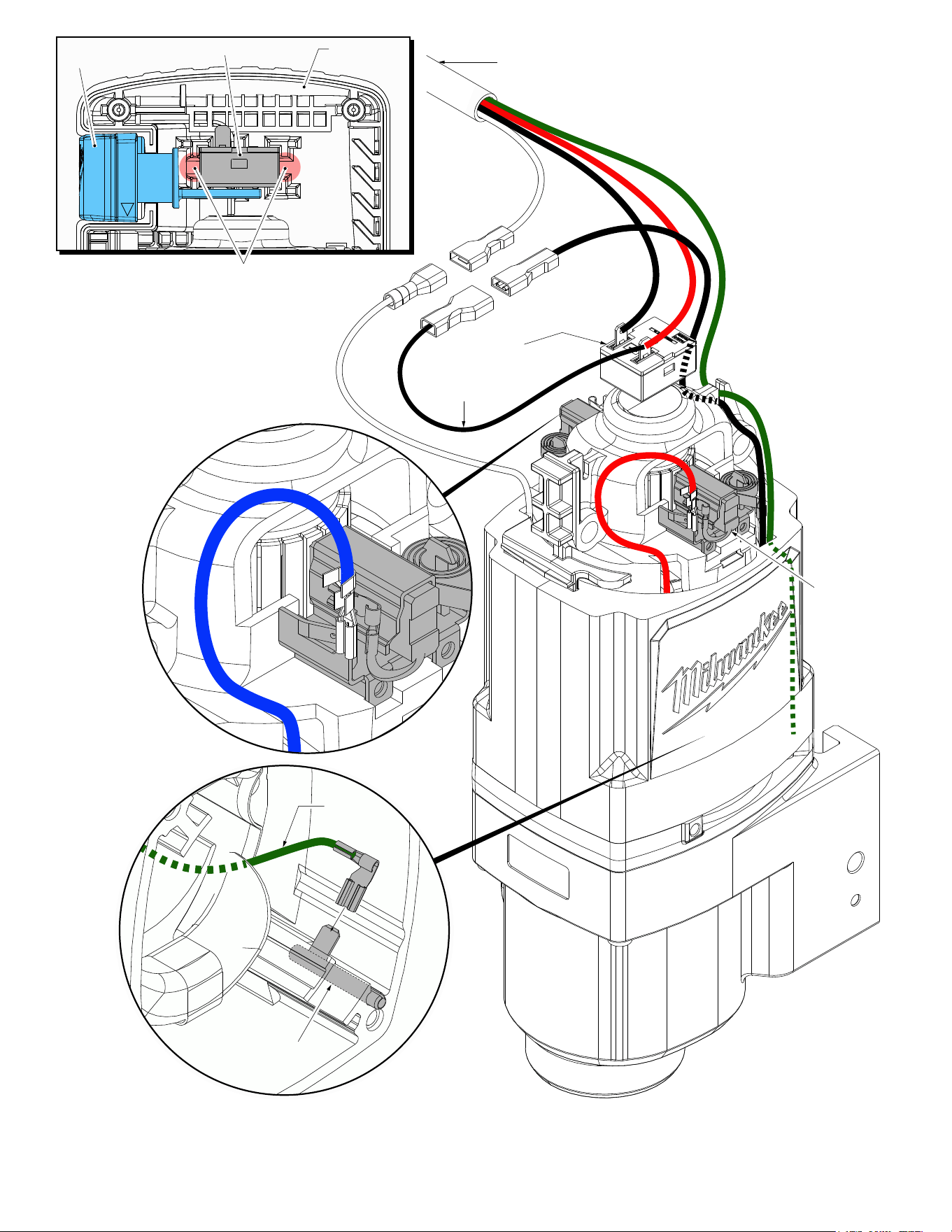
2 pin terminal cavity for the
LED Switch Plug
4 pin terminal cavity for the
LED Light Plug
PCBA
Ground Wire
Opening for
LED Switch Plug
and LED Light Plug
Connect red, white and black leadwire assem-
blies from PCBA/ Electronics Assembly (175) to
corresponding red, white and black leadwire
assemblies of Connection Cord (67).
These three wires from
the Connection Cord
are gathered at this
point with a wire
tie (not shown).
NOTE:
Green ground wire from Connect-
ion Cord is not shown in this view
and IS NOT to be wire tied.
Wire tie
(not shown)
Ground
wire from
Power
Cord
Ground wire
from the
Connection
Cord
Power Cord
Terminal Block
22-56-0475
Feed LED Switch Plug
Assembly through the
opening in Magstand
Base here.
LED Switch
Assembly (92)
Housing
Support (79)
Route LED Light
Plug through open-
ing in Magstand
Base as shown.
Connection Cord (67)
On/Off
Switch (51)
Right Brush
Assembly with
blue field lead
Left Brush
Assembly with
red field lead
Ground Pin (60)
Ground
Wire
Bottom View of
Motor Housing (56)
Prior to installing the Switch (51), place the connected
insulated terminals of the white wires in back of switch
cavity of Motor Housing Support (58). Be sure that
terminals are firmly press to the back and the wires
are routed out the cavity side slots. Place the con-
nected insulated terminals of the black wires over
the white terminals and routed wires out the cavity
side slots. Place the switch over the white and
black wire assemblies.
Insert tab on bottom of switch into corresponding
hole on arm of Switch Button Assembly (170).
Switch Button
Assy. (170)
On-Off Switch (51) Housing
Support (58)
Terminal Contact
Wire Assy. (53)
SCREW TORQUE CHART
Seat Torque
Item Part Number (Kg./cm.) (In./lbs.)
7 06-82-0040 28-33 24-28
15 05-81-1410 4-6 3-5
16a --------------- 6-10 5-8
38 43-33-0025 4-8 3-7
41 05-83-0020 15-20 13-17
46 06-81-0007 7-10 6-8
48 06-82-3006 13-17 11-14
52 05-78-0910 12-18 10-15
59 06-82-1080 10-15 8-13
61 06-82-0018 15-20 13-17
64 06-82-0009 28-33 24-28
65 06-82-0011 15-20 13-17
68 43-12-0055 460 399
76 05-74-0014 35-40 30-34
79 05-83-0010 3-7 2-6
83 06-83-0015 4 3
84 05-81-2787 28-33 24-28
89 06-75-3050 28-33 24-28
99 --------------- 20-25 17-21
127 05-74-0013 25-30 21-26
133 05-80-2787 10-15 8-13
187 42-04-0200 50-75 43-65
Model 2787-20 Shown