
INSTALLATION, OPERATION, AND
MAINTENANCE MANUAL FOR TANKLESS ELECTRIC WATER HEATERS
PROSERIES XTP™
i
IMPORTANT SAFETY INFORMATION
READ ALL INSTRUCTIONS BEFORE USING
DANGER
Indicates an imminently hazardous situation which, if not avoided, will result in death
or serious injury.
WARNING
Indicates a potentially hazardous situation which, if not avoided, could result in death
or serious injury.
CAUTION
Indicates a potentially hazardous situation which, if not avoided, may result in minor
or moderate injury.
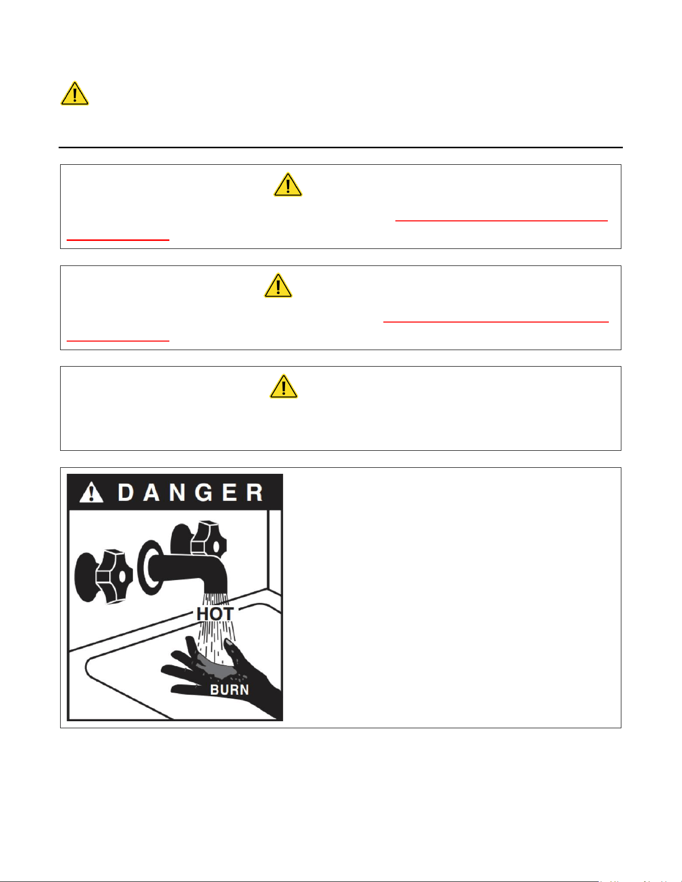
Hot water can be dangerous. There is a high scald
potential if the thermostat is set too high.
Water temperatures over 125 °F (51 °C) can cause
severe burns or scalding resulting in death.
Hot water can cause first degree burns with
exposure for as little as:
3 seconds at 140 °F (60 °C)
20 seconds at 130 °F (54 °C)
8 minutes at 120 °F (48 °C)

ii
IMPORTANT SAFETY INFORMATION
READ ALL INSTRUCTIONS BEFORE USING
1. You must read and follow all
instructions. Serious bodily injury or
death could occur if you ignore this
warning.
2. All circuit breakers and/or disconnect
switches servicing the heater must be
turned off when installing, uninstalling,
or repairing this water heater.
3. The unit must be installed by a
licensed electrician and plumber.
4. The unit must be wired in accordance
with the current version of the
National Electrical Code (US) or
Canadian Electric Code (Canada).
5. This installation must comply with all
national, state, and local plumbing and
electrical codes.
6. When the heater is not within sight of
the electrical circuit breakers, an
additional local means of
disconnection of all ungrounded
conductors must be provided that is
within sight of the appliance or a
circuit breaker lockout must be used.
(Ref. NEC 422.31)
7. Per UL 499, this water heater is not
required to be installed with a
Temperature and Pressure relief valve
(T&P). However, local codes may vary.
In case a T&P relief valve is required, it
must be installed on the outlet hot
water line between the heater and the
isolation valve.
8. If the Eemax Tankless Water Heater is
installed in a location where water
damage could occur in the event of a
leak, it is recommended that a drip
pan be installed and connected to a
suitable drain. Alternatively, an active
water leak detector and shut off valve
can be installed to turn off your water
supply in the event a leak is detected.
9. If water supply has a high mineral
content, a water softening system is
recommended. Damage to the water
heater resulting from scale or hard
minerals will not be covered under
warranty.

iii
IMPORTANT SAFETY INFORMATION
READ ALL INSTRUCTIONS BEFORE USING
10. When the heater is installed in a well
water system or if the plumbing
system is prone to introducing air into
the heater, it is highly recommended
that an air separator be installed in the
cold water feed to the heater to avoid
possible failure of the heating element
and/or heating chamber.
11. In accordance with NEC guideline, this
water heater is designed for a
maximum continuous duty cycle of 3
hours at 100% power output. . After
three hours heater should be powered
down for long enough to return heater
and electrical infrastructure to
ambient temperature. Exceeding this
rating, without proper pause, could
damage the heater and void the
warranty.
12. Provide an uninterrupted supply of
potable water to the heater at a
constant minimum pressure of 35PSI
(based on model) and maximum
pressure of 150 PSI.
13. Use of Water Hammer Arrestors in
applications with excess pipe lengths
or fast acting valves is strongly
recommended. Neglecting to do so will
damage the heater and void the
warranty.
14. This heater must be installed in a
location where it is not subject to
freezing temperatures unless supplied
with factory installed freeze
protection.
15. Properly purge air out of system
before power is applied. Purge water
through the system for a minimum 2
minutes at the maximum flow
available. During this process, close
and open the drain valve 3 times to
dislodge any air before power is
applied. Utilizing the recommended
boiler drain on the outside of the
heater is an acceptable means to
purge the system.
16. Applications located above the point
of use, i.e. in a drop ceiling must take
additional precautions for continuous
air elimination to prevent
interruptions to the hot water service.
Use of an air separator/scrubber is
required for this type of installation.
Recommended installation schematics
can be found in the APPLICATION
SCHEMATICS section of this manual.

iv
IMPORTANT SAFETY INFORMATION
READ ALL INSTRUCTIONS BEFORE USING
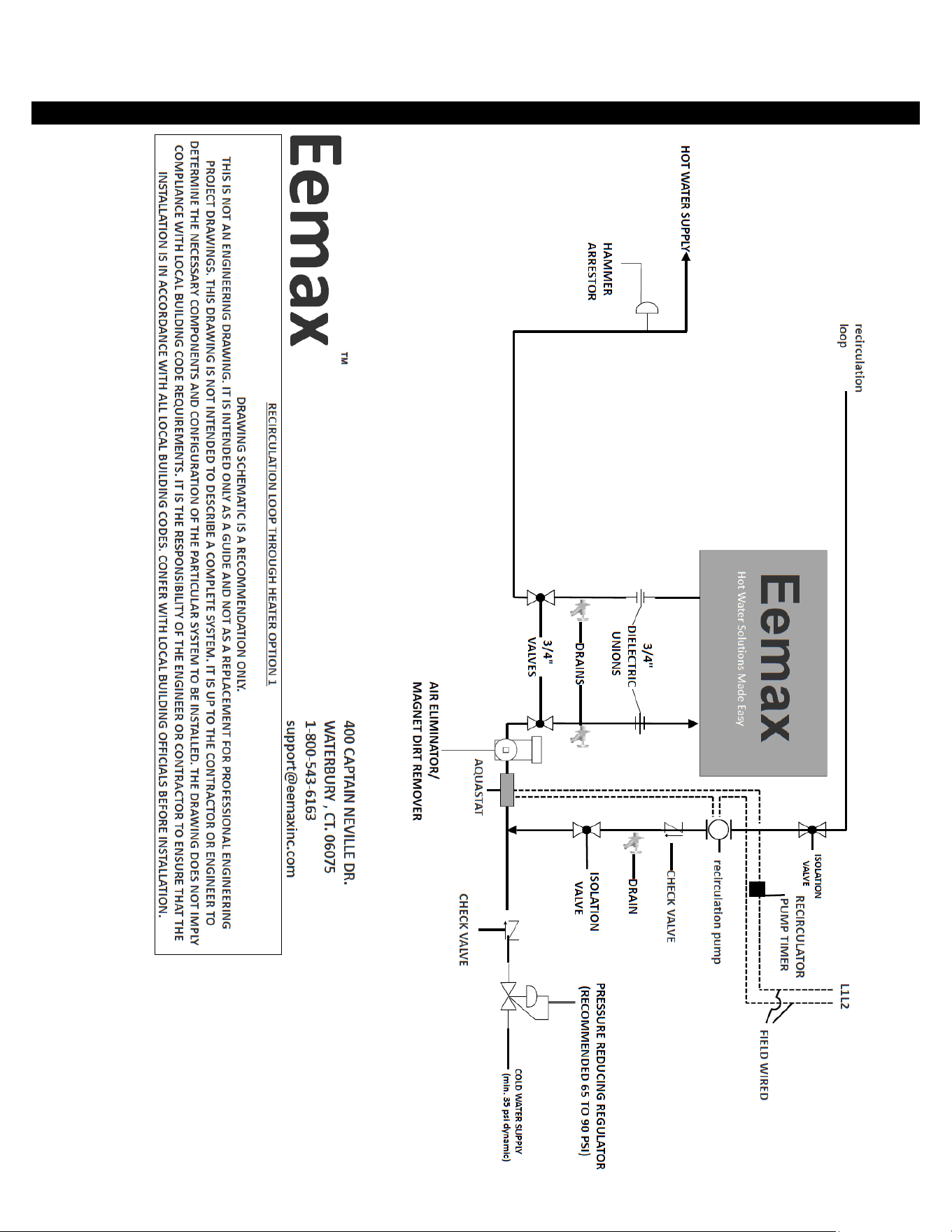
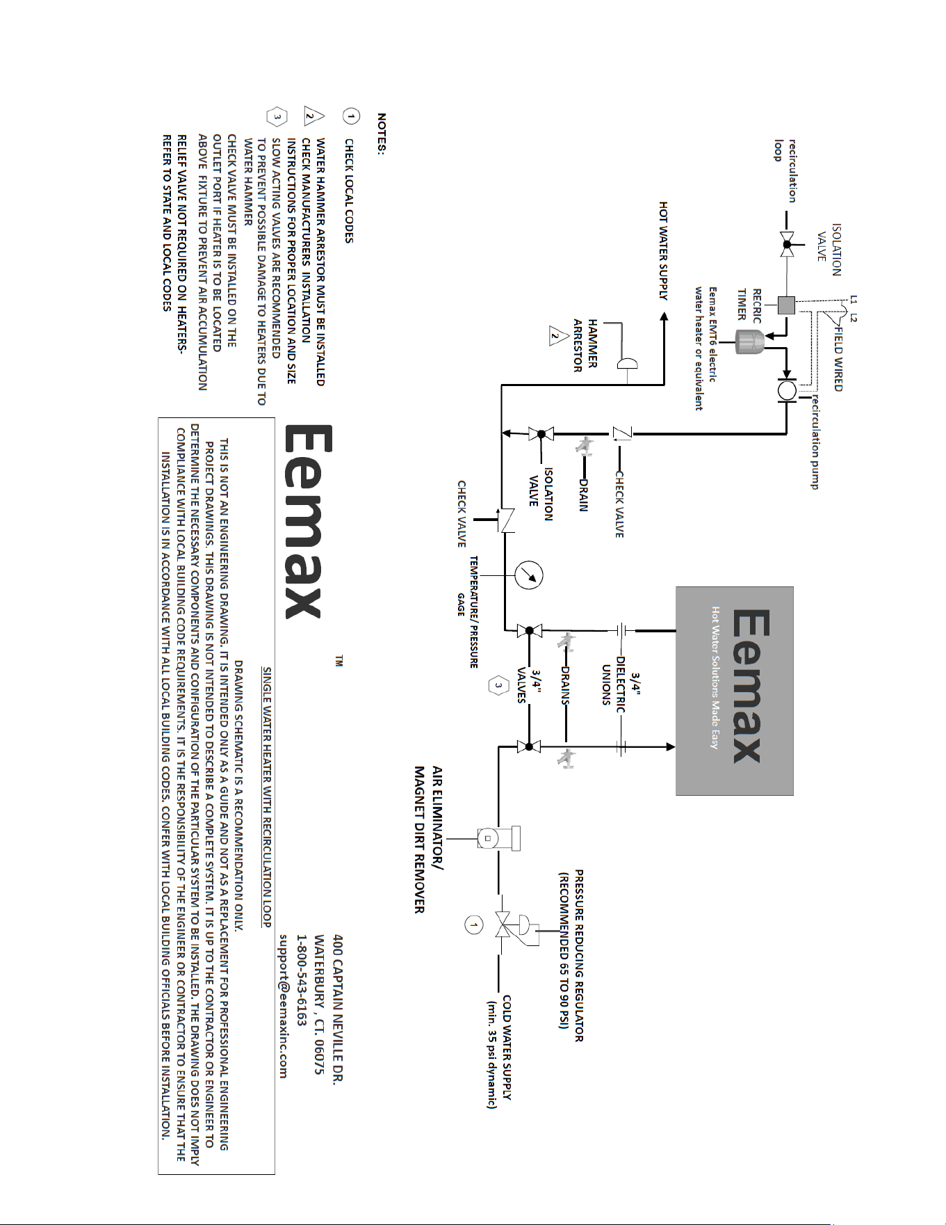
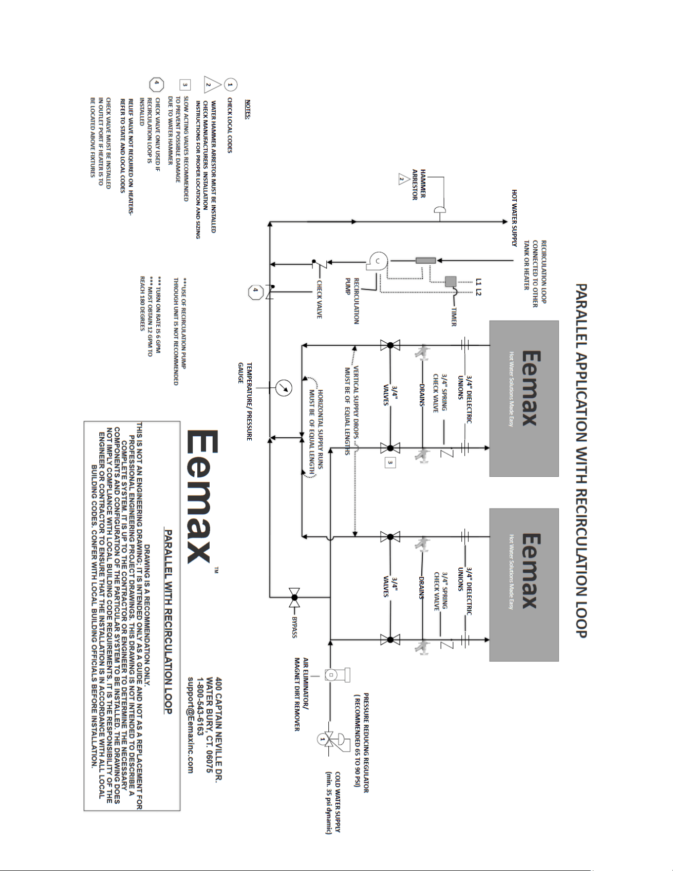
17. Applications with the use of a circulating pump recirculation circulator must be
installed according schematics.
18. Should applications call for the use of antifreeze. A mixture of Propylene Glycol is the
only recommended antifreeze. The use of Ethylene glycol antifreeze is strictly
prohibited.
TABLE OF CONTENTS
TABLE OF CONTENTS ...................................................................................................................... IV
ABOUT YOUR PROSERIES XTP ............................................................................................................ 5
BEFORE INSTALLATION ...................................................................................................................... 6
MOUNTING THE HEATER TO THE WALL ............................................................................................. 6
ELECTRICAL HOOKUP ........................................................................................................................ 8
PLUMBING HOOKUP ....................................................................................................................... 10
COMMISSIONING THE WATER HEATER ............................................................................................ 13
SOFTWARE FEATURES ..................................................................................................................... 15
START-UP PROCESS ......................................................................................................................... 17
MONITORING & PREVENTIVE MAINTENANCE .................................................................................. 20
TECHNICAL SUPPORT ...................................................................................................................... 21
APPLICATIONS SCHEMATICS ............................................................................................................ 23
REPAIRS AND OPTIONS ................................................................................................................... 37
WIRING SCHEMATICS ...................................................................................................................... 39
5
ABOUT YOUR PROSERIES XTP
Congratulations on the purchase of ProSeries XTP! Read all set-up procedures and operating instructions carefully to
ensure maximum performance and energy savings from the water heater. It is important that the heater be installed
in accordance with stated instructions and the electrical and plumbing codes applicable to your area. Read this
manual thoroughly for important operating instructions and tips.
Tankless water heaters do not store hot water like conventional tank-type water heaters. ProSeries XTP tankless
electric models contain high powered sheathed technology heating elements that heat water instantly on-demand.
When there is a hot water demand, the flow meter within the heater recognizes the demand and initiates the
heating process. The flow meter measures the water flow rate while two thermistor sensors measure the incoming
and outgoing water temperature. The microprocessor controller receives this information and determines the
amount of power to send to the heating elements to heat the water to the desired temperature. Eemax tankless
electric water heaters only use as much power as needed by modulating the heating elements from 0 to 100%.
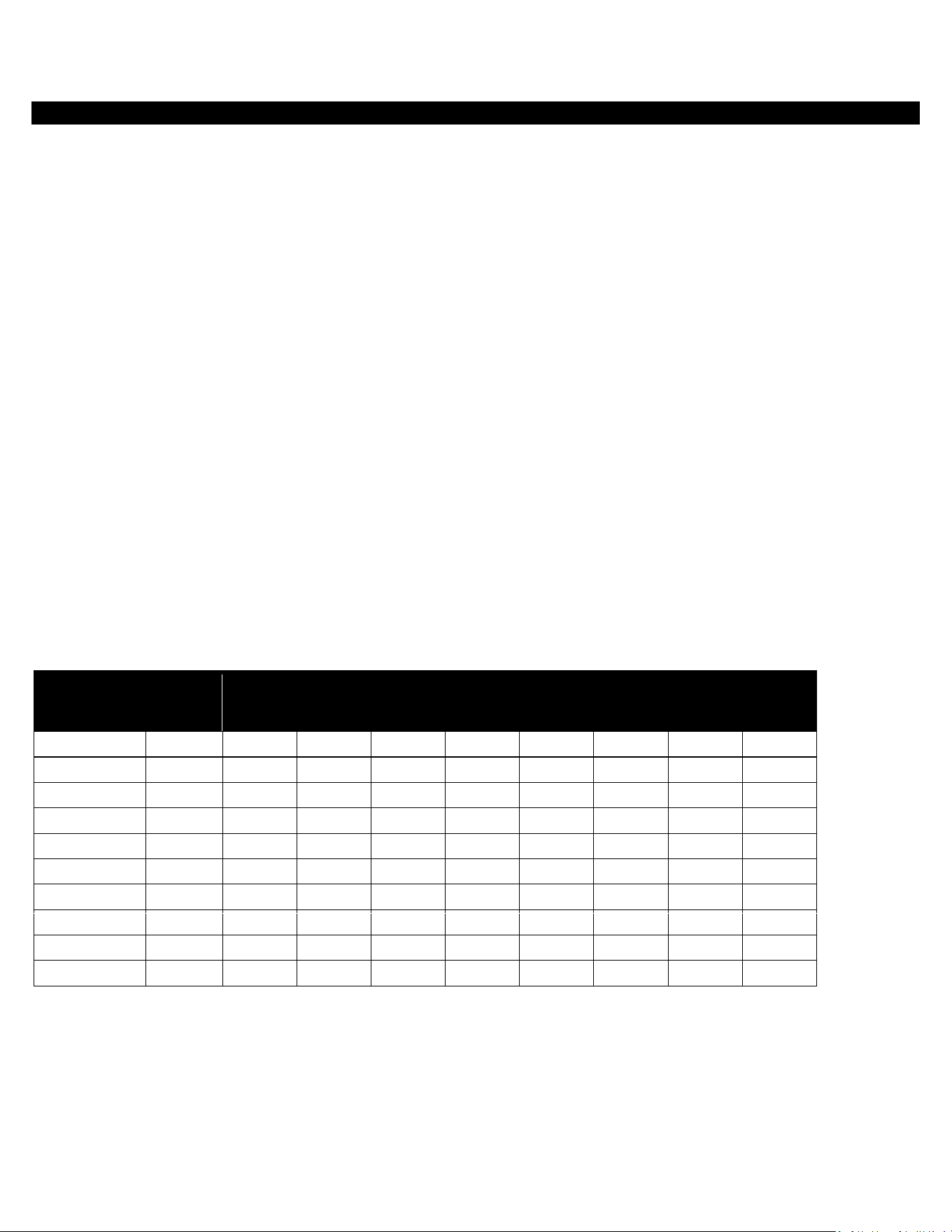
All electric tankless water heaters have a maximum flow rate. If this flow rate is exceeded, the heater will not be
capable of fully heating water. The amount of water that can be heated depends on the model and the incoming
water temperature. See diagram below to determine the maximum flow rates.
Dimensions:
All Models: Height=18.4” Width=20.5” Depth=5.5”
Temperature Rise at Specified Flow Rate (°F)
MODEL
TURN-
ON
GPM
0.5
GPM
1.0
GPM
2.0
GPM
3.0
GPM
4.0
GPM
6.0
GPM
8.0
GPM
10.0
GPM
XTP016480
0.5
-
109
55
36
27
22
18
14
XTP020480
0.5
-
137
68
46
34
27
23
17
XTP024480
0.5
-
-
82
55
41
33
27
20
XTP027480
0.5
-
-
92
61
46
37
31
23
XTP036480
0.5
-
-
123
82
61
49
41
31
XTP048480
0.5
-
-
-
109
82
66
55
41
XTP054480
0.5
-
-
-
123
92
74
61
46
XTP018208
0.5
-
123
61
41
31
25
20
15
XTP024208
0.5
-
-
82
55
41
33
27
20
XTP032208
0.5
-
-
107
71
53
43
36
27
If you have questions at any time, please contact us directly at:
Manufacturer’s National Service Department
400 Captain Neville Dr. Waterbury, CT 06705
Phone: 1-(800)- 543-6163
6
BEFORE INSTALLATION
READ THESE INSTRUCTIONS THOROUGHLY AND COMPLETELY PRIOR TO INSTALLATION & USE. FAILURE TO
FOLLOW INSTRUCTIONS COULD CAUSE PROPERTY DAMAGE, SERIOUS PERSONAL INJURY, OR DEATH.
By installing this product, you acknowledge the terms of the manufacturer’s warranty. Once the heater is installed, do not return
product to the place of purchase. If you have any questions regarding the warranty or product return policies, please contact
Manufacturer’s national service department at 1-(800) 543-6163.
Before installation, inspect all components. The package includes:
ProSeries XTP unit
Mounting bracket with locking screw
Warranty card
Registration card
Recommended equipment for installation:
Electric drill for pre-drilling holes
Phillips Head screwdriver
Flat Head screwdriver
Tape measure/ruler
¾” Dielectric Unions
¾” shut off valves
¾” check valve
Air Eliminator/ Magnet Dirt Remover
Pressure Reducing Regulator
Boiler drains (may be beneficial)
Adjustable wrench
Pipe cutter (may be beneficial)
Pencil (used to mark measurements)
Level
MOUNTING THE HEATER TO THE WALL
Follow the mounting instructions below as appropriate to your installation. Eemax recommends the heater be installed close to the
point-of-use.
CAUTION
This heater must be installed in a location where it is not subject to freezing
temperatures, unless supplied with factory installed freeze protection.
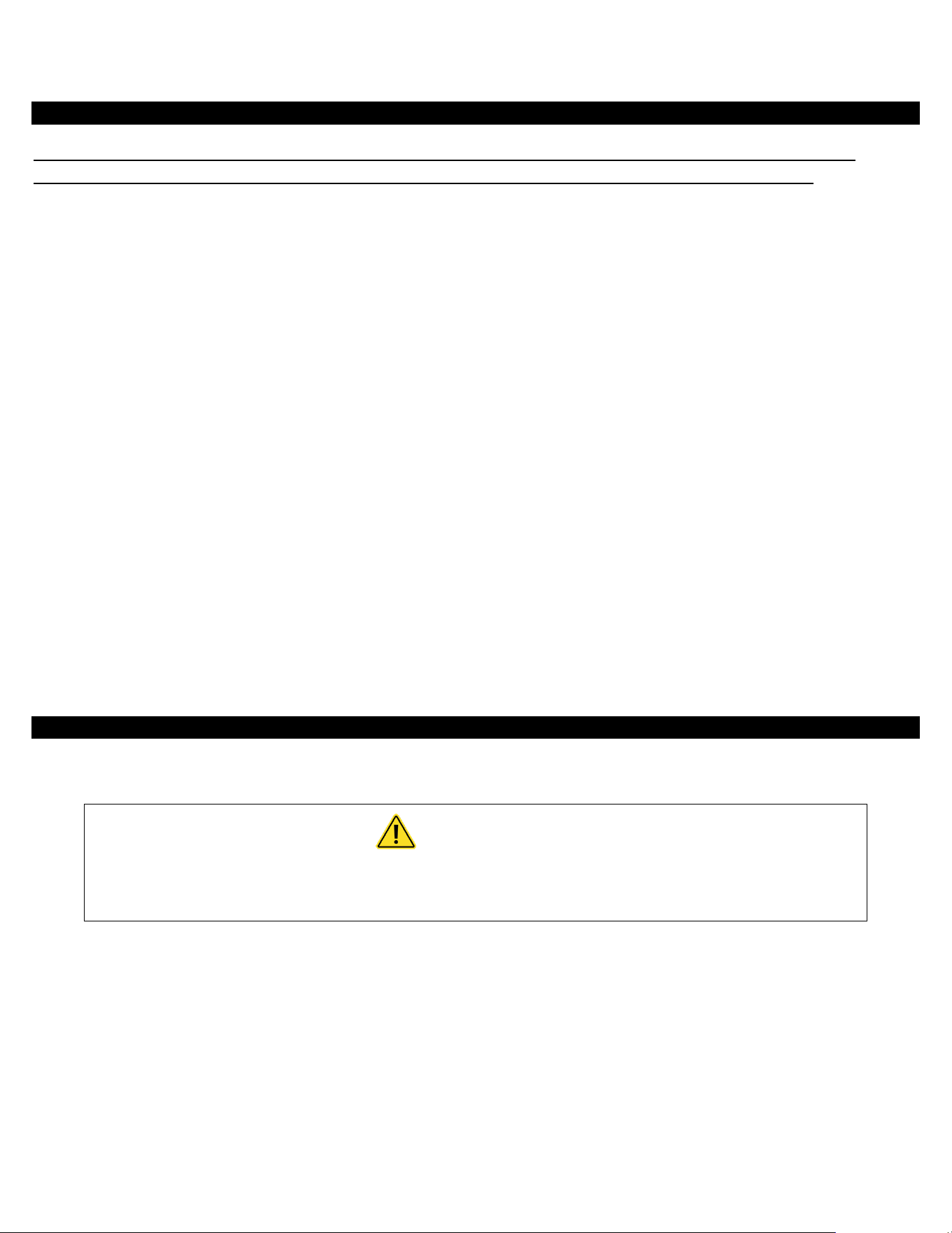
Install the product upright with the water connections facing downward for best performance. Mounting the heater in an alternate
(horizontal) orientation is acceptable. When mounting the unit in a horizontal orientation do not use the included bracket and
ensure the fittings are facing to the right as shown below. Note that the display readout and buttons will not rotate to accommodate
for this alternate orientation. The orientation of the display and buttons are not rotatable. Refer to the specified orientations below
for proper installation.
7
\
ProSeries XTP models are approved for zero clearance to combustible surfaces such as plywood.
Above clearances are recommended for service and installation.
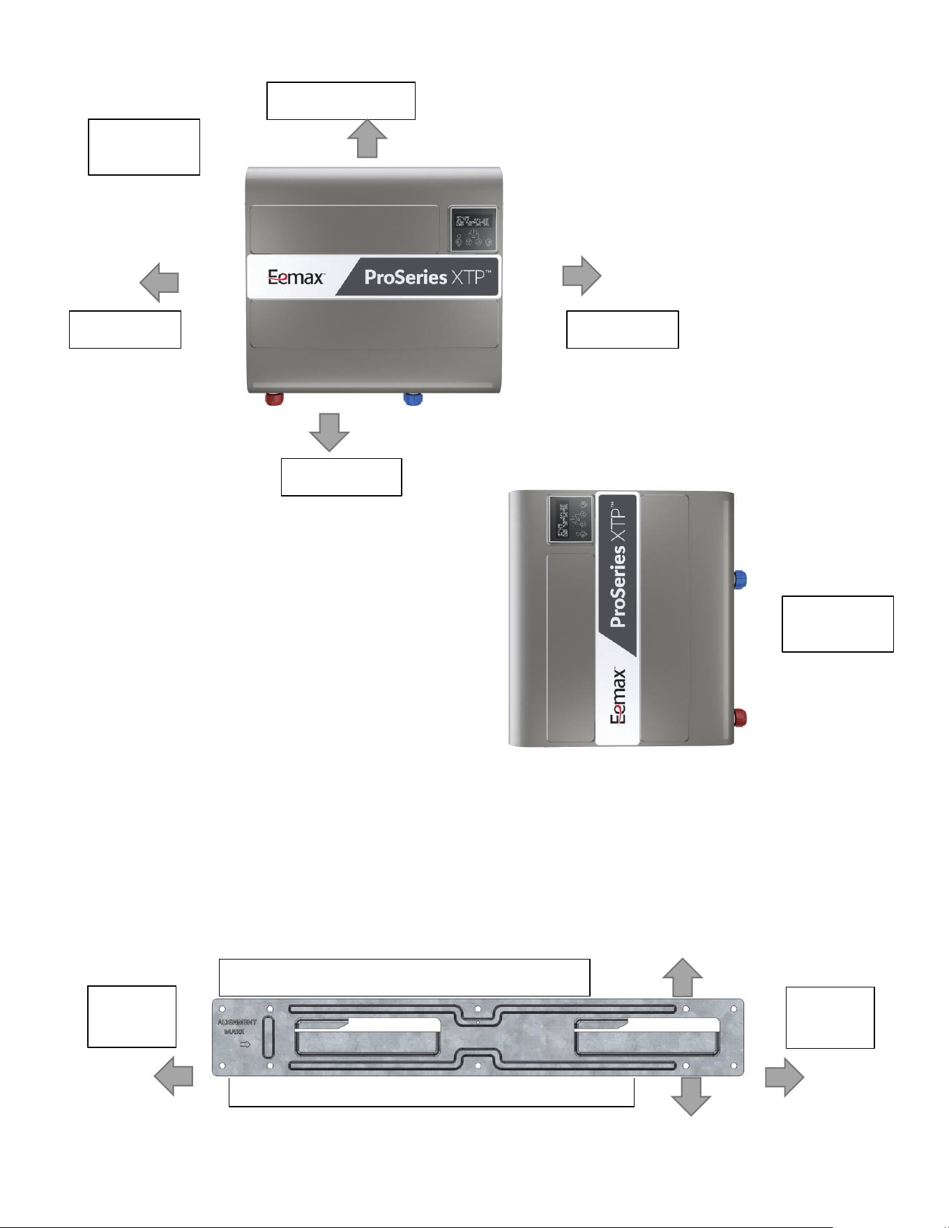
1. Locate the best position to mount the unit. Check clearances around the unit according to the diagram below. Measure from
the top, bottom, left & right sides of the bracket to ensure proper clearances.
Hang the slide lock wall mounting bracket utilizing the appropriate anchors for the wall in at least 4 hole locations.
10" Top Clearance
8" Clearance
8" Clearance
18" Clearance
Upright
Installation
8"
Clearance
Measure 13" from top edge for 10" Top Clearance
Measure 30.5" from bottom edge for 18" of clearance
8"
Clearance
Alternate
Installation
8
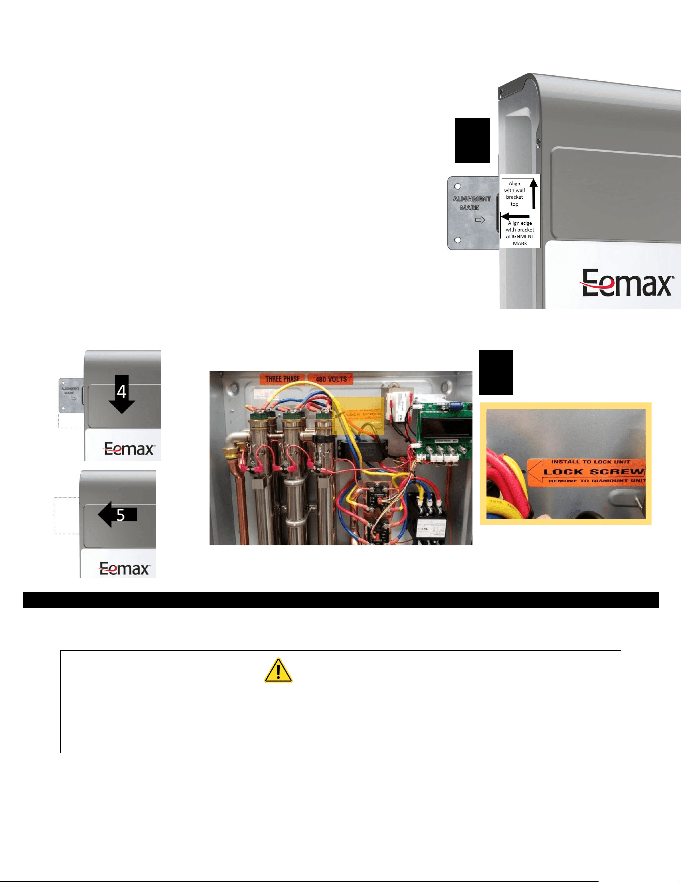
2. Remove the locking screw from the center of the slide lock bracket (to be
used in step 8)
3. Hang the unit on the bracket by aligning the left edge of the enclosure with
the alignment mark on the wall bracket and the top edge of the wall
bracket with the top edge of the alignment label on the front cover.
4. Slide the unit down onto the bracket until it stops, indicating that the wall
bracket is holding the weight of the unit.
5. Slide the unit to the left to until it stops. The stop is aligned such that the
unit will hide the wall mount bracket.
6. Test the bracket by lifting the unit upwards – it should not come free
7. Remove the cover
8. (Optional) Insert the locking screw through the center of the back plate and lightly hand tighten. This will prevent unwanted
sliding of the unit, i.e. tampering or accidental.
ELECTRICAL HOOKUP
Eemax recommends that the heater is installed and serviced by a licensed plumber and electrician.
WARNING
Before beginning any work on this installation, be sure that the electrical breaker is
"off" and that all mounting and plumbing work has been completed per these
instructions.
This heater must have its own independent circuit using insulated, UL listed, wire conductors (3 conductors plus ground) of the
appropriate size suitable for up to 90° C and protected by the correctly rated circuit breaker. For recommended conductor, ground
and breaker ratings refer to the chart below:
See chart on next page.
3
8
9
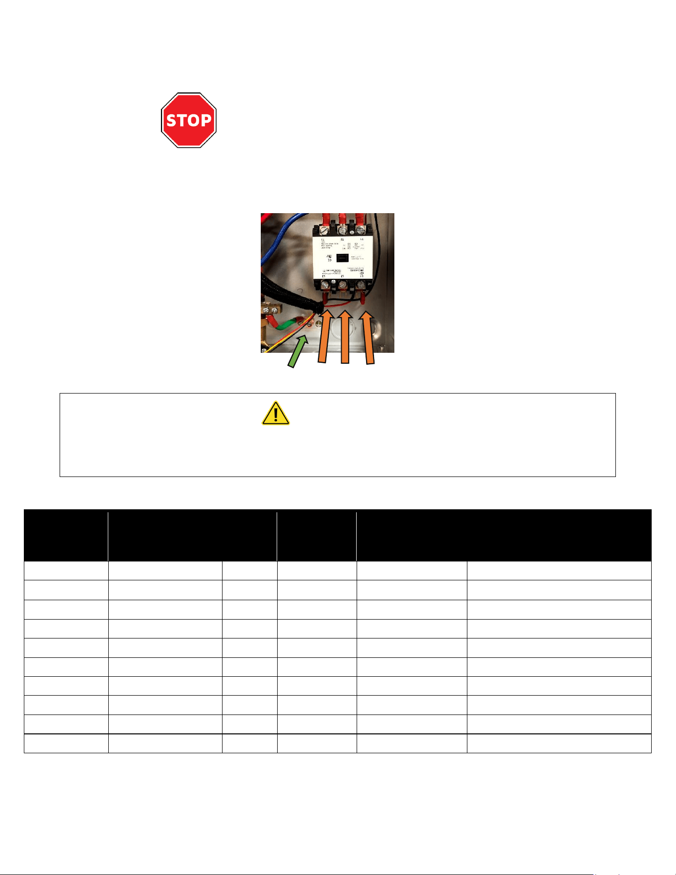
Before starting any electrical work: VERIFY there is
no power at the heater
The field wiring power conductors are to be secured to the L1, L2 and L3 connectors on the contactor(Fig. 1) .The
ground is to be secured to the GND connector to the left of the contactor.
Fig. 1
WARNING
Failure to ground the system may result in death, serious injury, and/or property
damage.
Electrical specifications
MODEL
VOLTS
THREE PHASE
DELTA
KW
TOTAL
AMPS
RECOMMENDED
WIRE SIZE (CU)
90° C
RECOMMENDED MINIMUM
BREAKER SIZE (PER NEC –
INTERMITTENT DUTY)
XTP016480
480
16
20
14
20
XTP020480
480
20
25
12
25
XTP024480
480
24
29
10
35
XTP027480
480
27
33
10
35
XTP036480
480
36
44
8
50
XTP048480
480
48
58
6
60
XTP054480
480
54
65.0
4
70
XTP018208
208
18
50.0
8
50
XTP024208
208
24
67
4
80
XTP032208
208
31.2
87
3
100
A ground terminal (or a wire connector marked "G", "GR”, "Ground", or "GROUNDING") is provided within the
enclosure. To reduce the risk of electric shock, connect this terminal or connector to the grounding terminal of the
electric service or supply panel with a continuous copper wire in accordance with your local electrical code.
GND L1 L2 L3
10
PLUMBING HOOKUP
Must flush line a minimum 2 minutes, at a maximum flow on initial start-up.
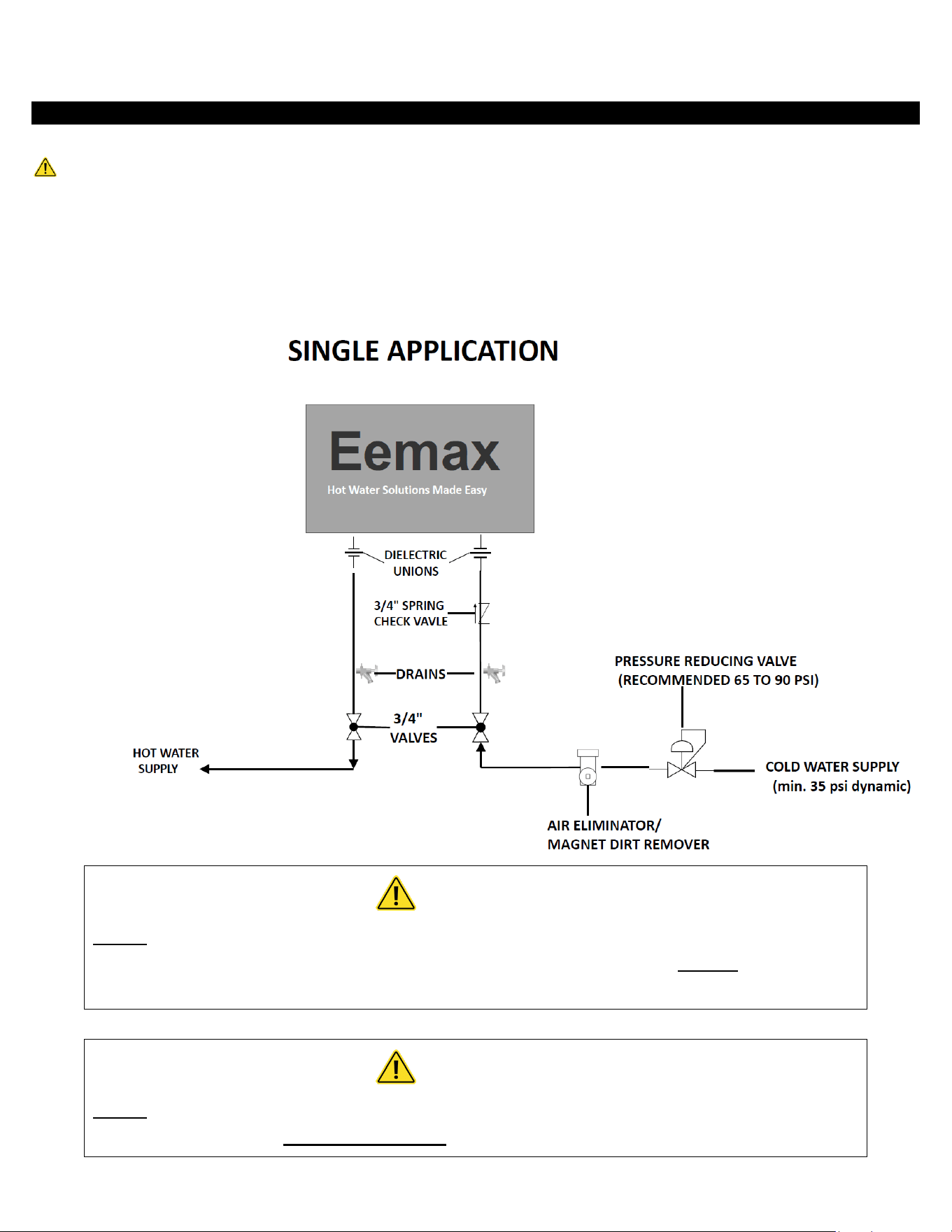
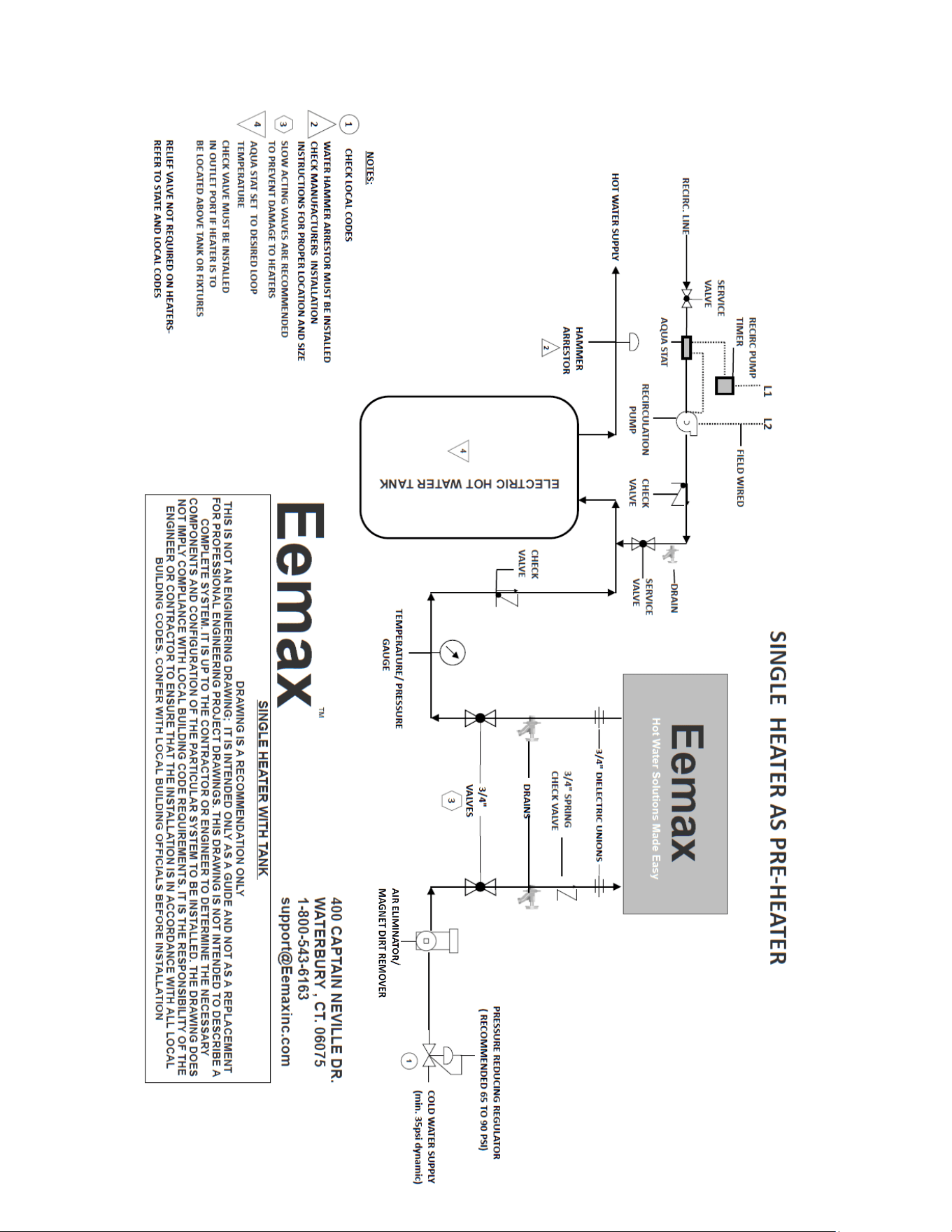
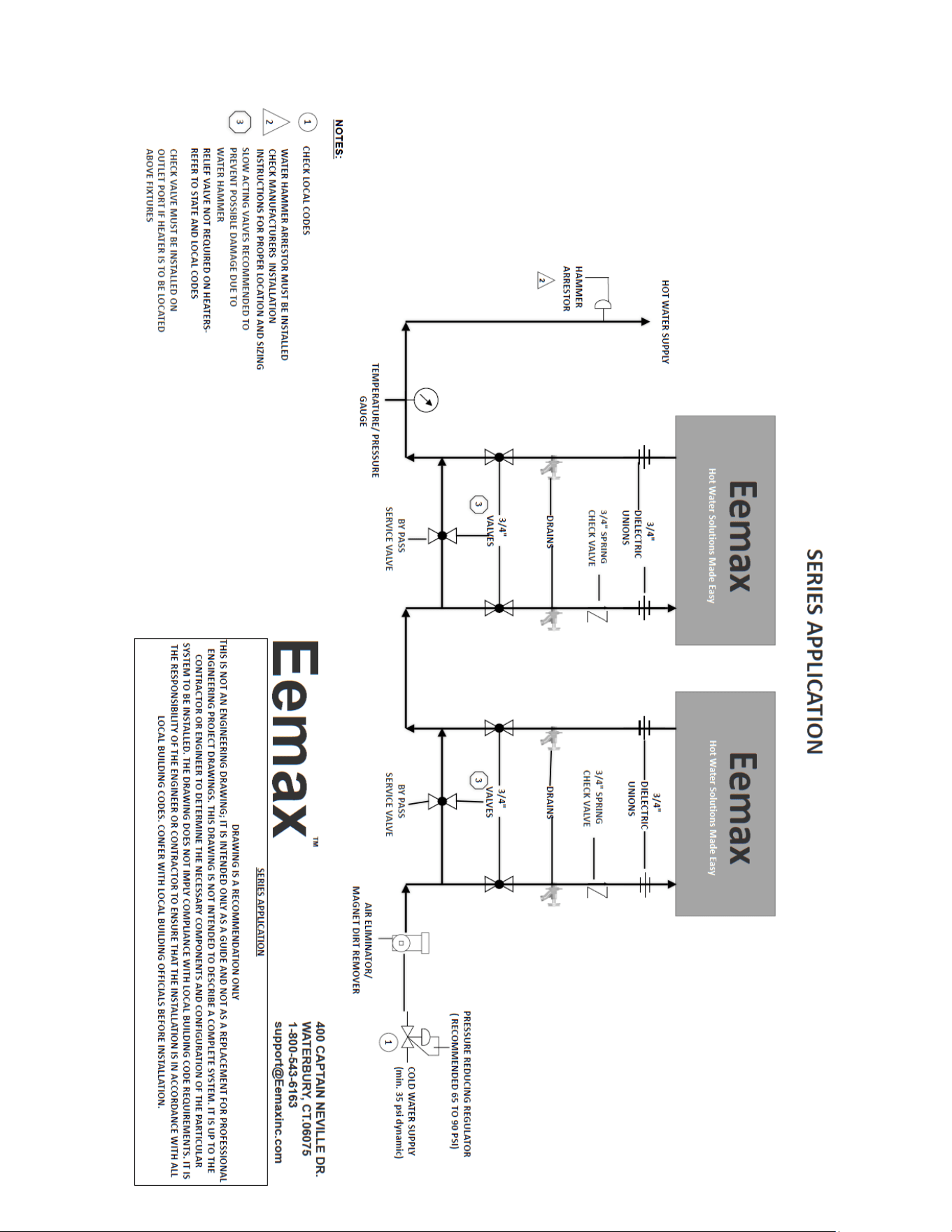
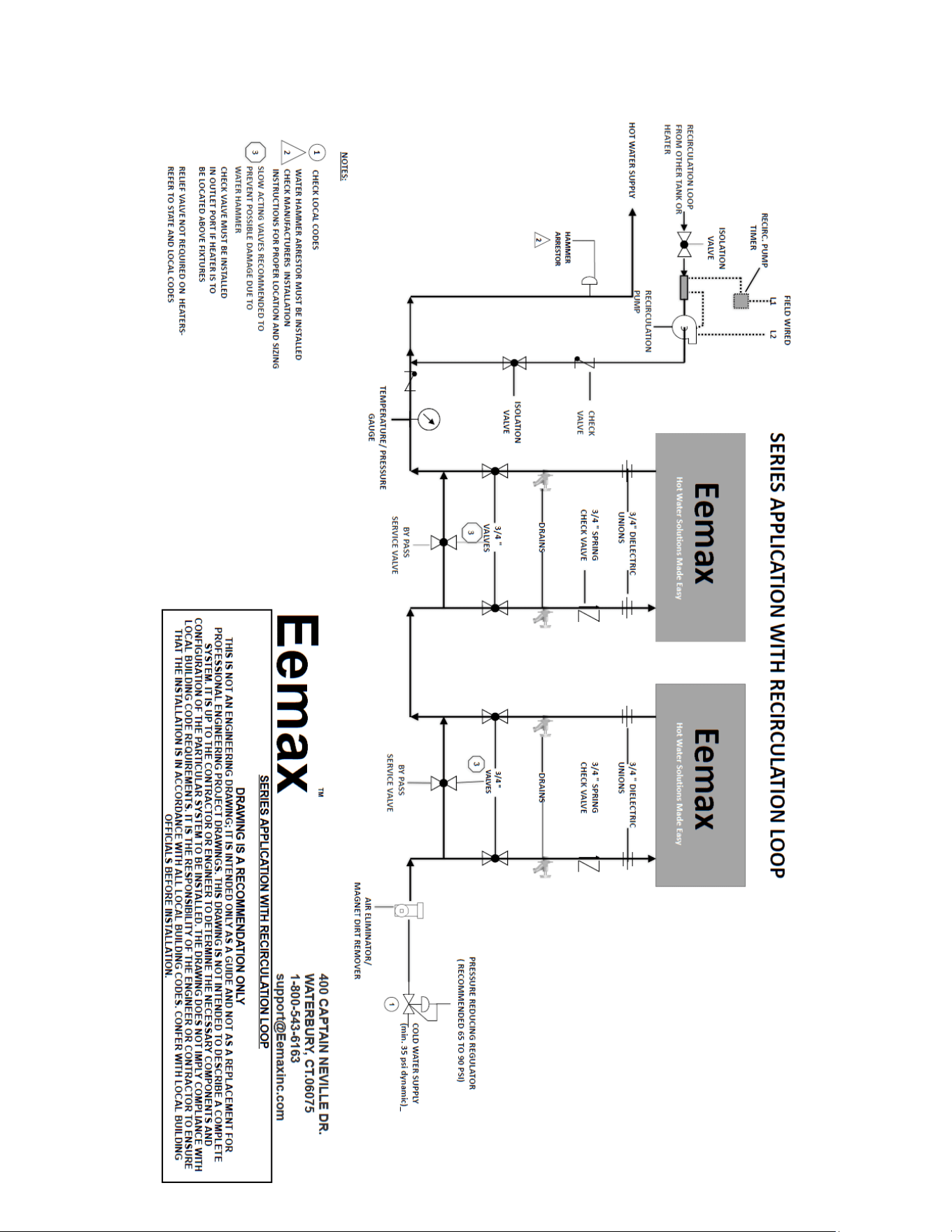
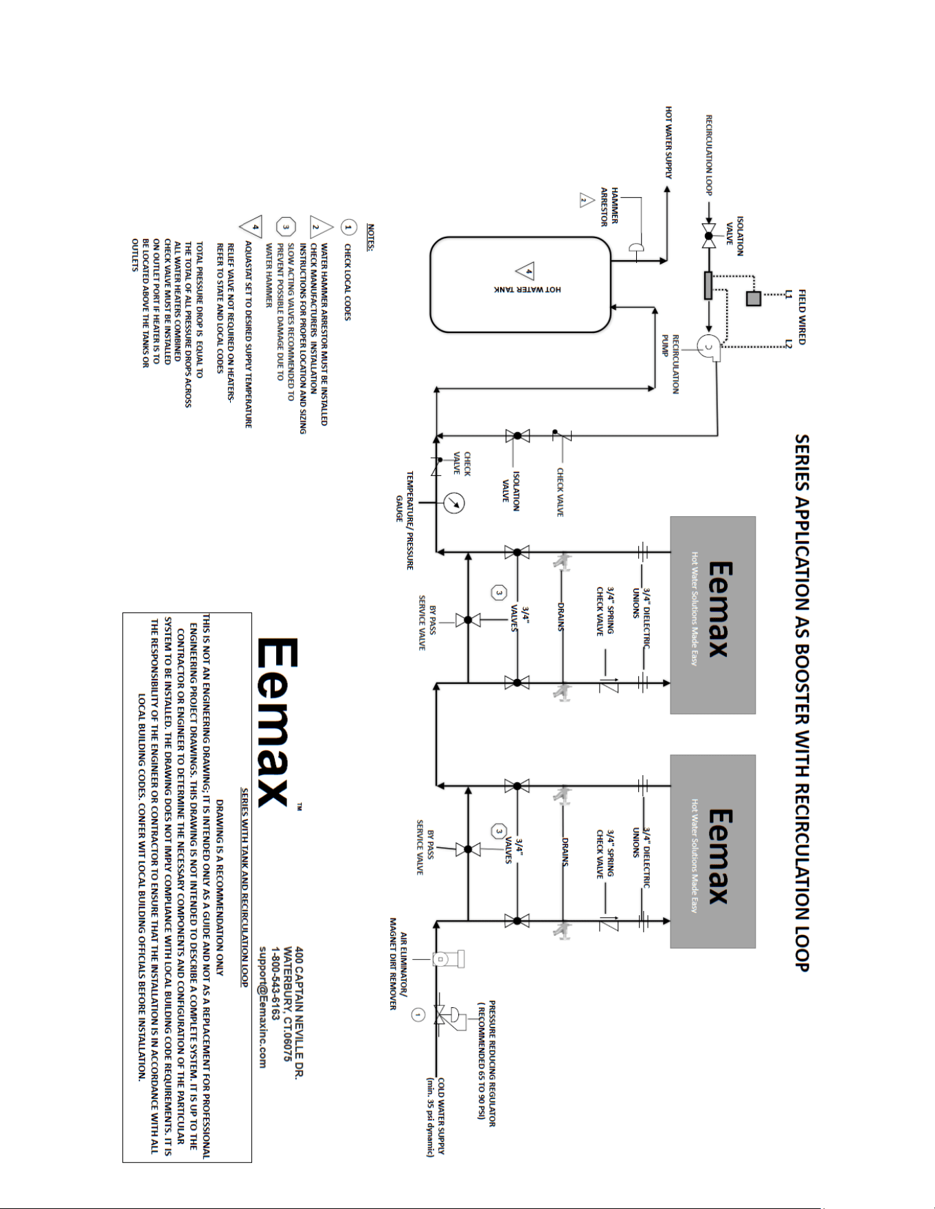
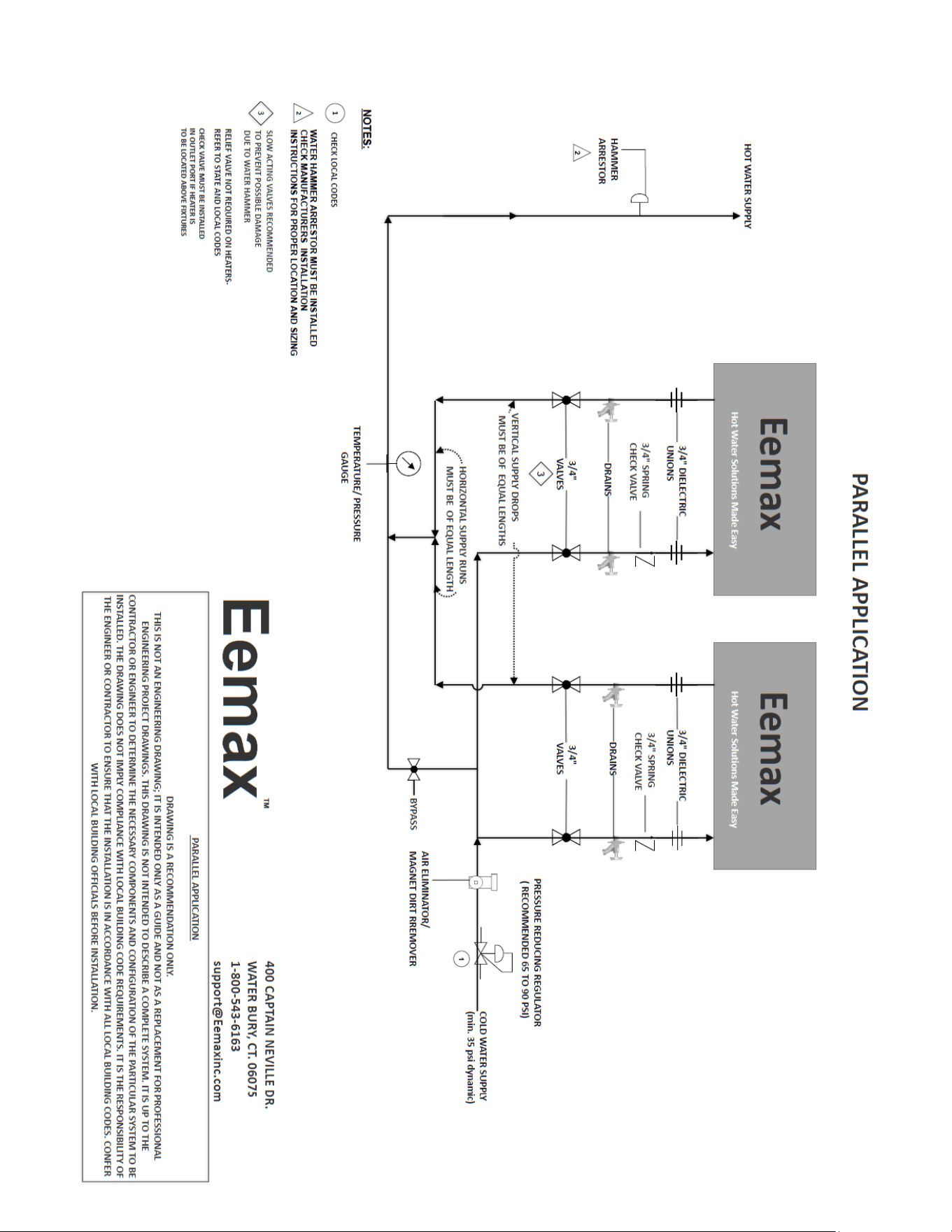
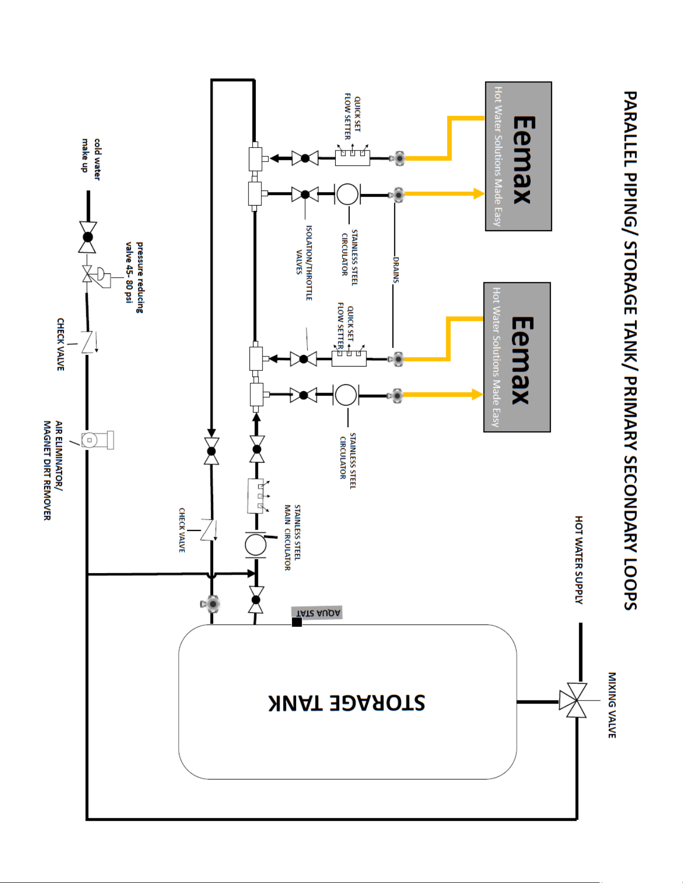
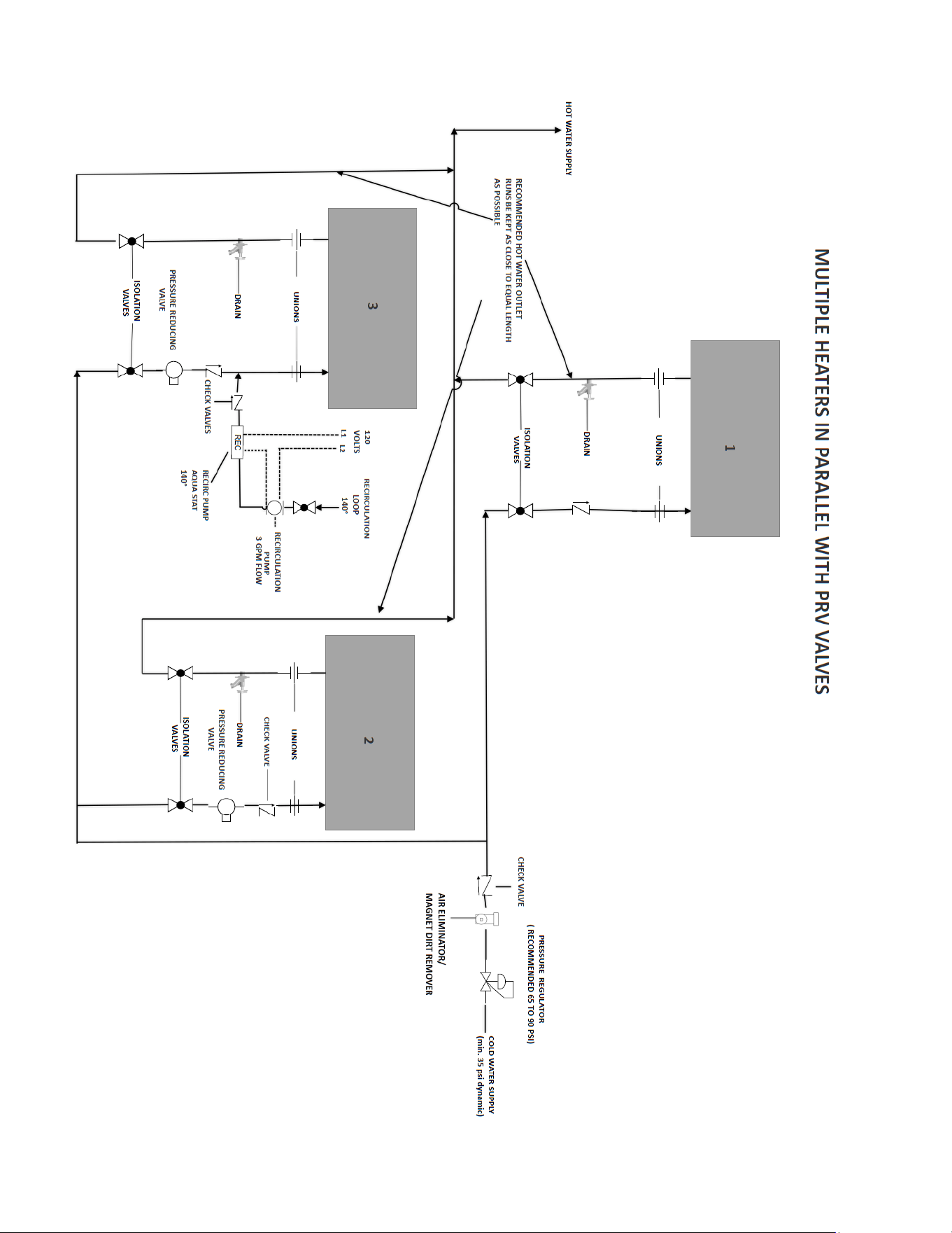
Reference the recommended installation diagram below. Additional installation diagrams for recirculation loops, multiple ProSeries
XTP units plumbed in series or parallel configurations, can be found in the APPLICATION SCHEMATICS section of this manual.
The heater is equipped with brass ¾” NPT fittings.
Make sure ONLY NPT fittings are used for connection to this heater.
Connect the cold water line with the inlet connection
(RIGHT fitting)
Connect the outlet pipe with
the outlet fitting
(LEFT fitting)
Do not reverse connections.
CAUTION
Never use pipe dope when making plumbing connections to this heater. Follow
standard industry practice with careful application of Teflon tape. Do not allow Teflon
tape to get into the heater.
CAUTION
Never solder any pipe connections attached to this heater – damage to the heater will
result. Doing this will void the warranty.
11
WARNING
Must flush out water heater for minimum 2 minutes at maximum flow on initial
start-up or after any service work has been performed. Close and open drain valve 3
times to remove any lodged air bubbles. Failure to do so may damage the heater.
Minimum inlet water pressure 35 psi dynamic.
Maximum water pressure not to exceed 150 psi. Recommended operating
pressure is 35 psi.
Use of a pressure regulator recommended.
Water supply inlet piping must be a minimum ¾” pipe diameter and it must be a
dedicated supply line. 1 ¼” minimum pipe diameter on trunk main when part of a
branch system.
The use of di-electric unions must be used on the inlet and outlet ports of the
water heater.
Recommended 40 mesh (1/64” or smaller) Y-strainer be installed in cold water
inlet to prevent debris from entering the water chambers. Blockage caused by
debris may cause element failure. Isolation valves recommended for servicing.
In applications where a long duty cycle is needed (more than 3 hours continuous
run time), or a short duty cycle (less than 30 sec. on time with less than minute off
time) please contact applications department. 1-800-543-6163
Hammer Arrestor: Systems with a large water volume, or long lengths of piping can
be susceptible to water hammer. The use of slow acting valves along with the
installation of a water hammer arrestor is highly recommended on all units. Failure to
install a water hammer arrestor can cause damage to water heater and void
warranty- refer to manufacturer’s installation manual for proper size and installation
location.

12
Proper water conditions must be maintained to prevent damage to the water heater.
CONSTITUENT (MG/L)
MAXIMUM ALLOWABLE
CONCENTRATION
BETTER
BEST
Alkalinity
50
25
10
Calcium
25
5
0.5
Carbon Dioxide
0
0
0
Chlorine
100
15
1
Free Chlorine
1
1
0.05
Iron
0.2
0.1
0.01
Magnesium as Mg
0.5
0.1
0.1
Magnesium as Mn
0.1
0.1
0.1
Nitrate
25
25
10
Oxygen
2
1
0.1
Silica
15
10
1
Sodium
50
10
1
Sulfate
25
25
1
Total Dissolved Solids (TDS)*
200
100
5**
Total Hardness
25
10
1
pH
6.5 – 8.5
6.5 – 8.5
6.5 – 8.5
Turbidity (NTU)
5
5
1
* NOTE: Total dissolved solids
** NOTE: Do not reduce the TDS beyond this amount or the water will be too aggressive
13
COMMISSIONING THE WATER HEATER
CAUTION
Before switching the electrical breaker "on", make sure the inlet and outlet ball valves
are fully open and water is flowing through all points of use for a minimum of 2
minutes at maximum flow. Open and close drain valve 3 times while purging to
remove any lodged air bubbles. Do not switch the breaker "on" if there is any
possibility the water in the heater is frozen.
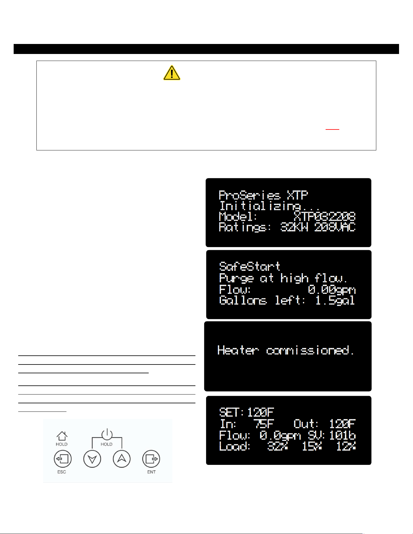
After verifying the heater has been purged of air (see above)
and the cover has been secured to the unit, turn the circuit
breaker/disconnect “ON” and observe the start-up sequence
on the display. The unit will first display a splash screen. The
Safe Start will commence. The unit needs to purge a volume
of 1.5 gallons of water at a rate of 0.5 GPM or greater, before
it will begin to heat. The heater cannot measure less than 0.5
GPM of flow rate and will not deduct volume from the “gallons
left” counter unless the flow rate is over 0.5 GPM. The
instantaneous flow rate is displayed on the Safe Start screen
for your reference. This procedure will run each time the
electrical power supply is turned off/on to the unit.
After Safe Start has completed, the LCD screen will briefly
display “Heater commissioned” and then the “Run” screen
which includes: SETPOINT TEMPERATURE in degrees F in the
upper left corner. Inlet temperature and outlet temperature
in degrees F are on the next line. Flow in GPM and the
Software version are on the third line. The load percentage on
each element is on the last line.
Below the display are 4 push buttons that are used to control
the function of the heater. Press the UP or DOWN buttons to
establish your desired set point temperature.
NOTE: DO NOT remove or replace the cover while the power
is on. Button malfunction may occur. If button malfunction
occurs reset the power to the unit after the cover is properly
secured in place.
14
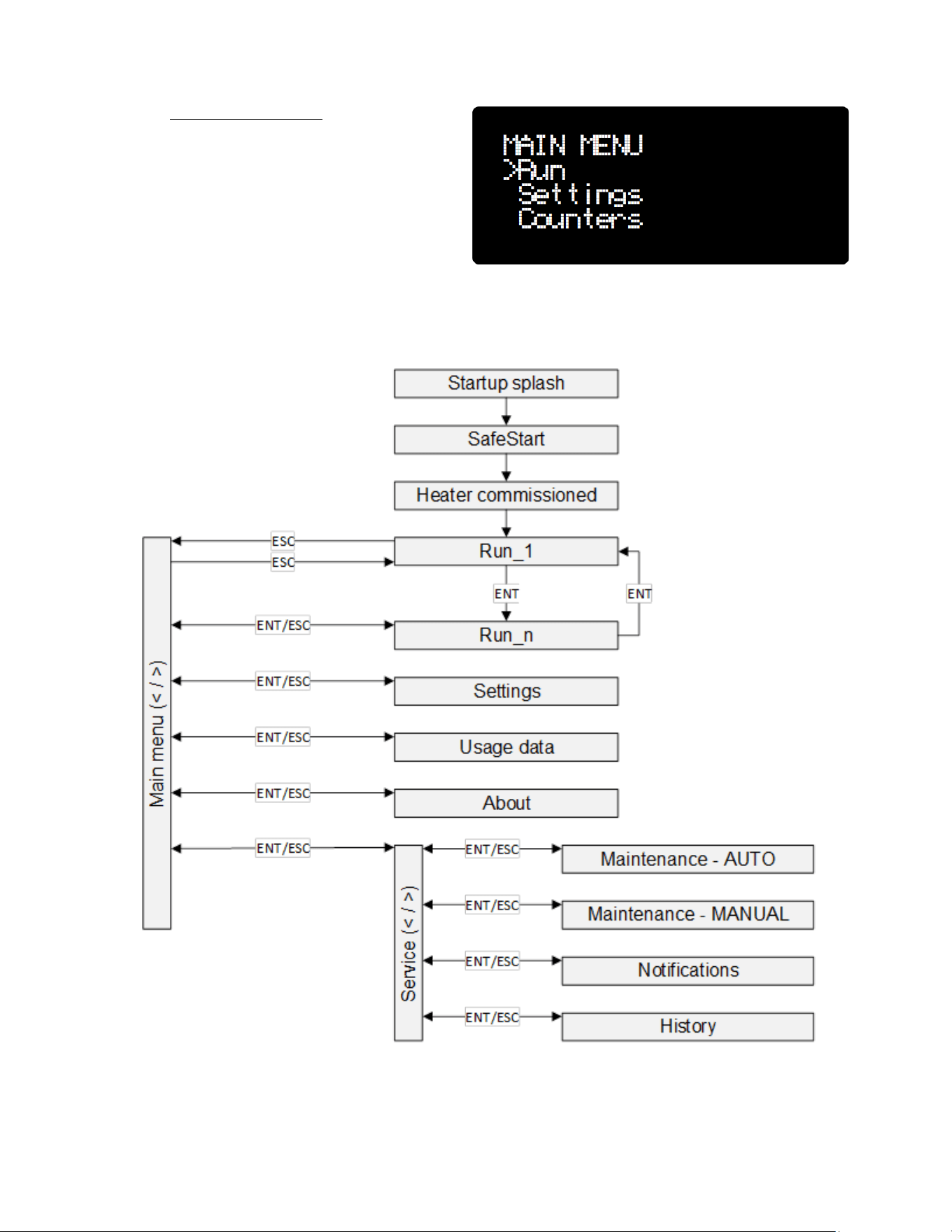
Navigating the menus:
Tap the left ESC button to move to the main menu screen.
Diagram 1 contains a flow chart of all of the sub-menus that
are accessible and which keys to press in order to navigate to
each menu.
To return to the “Run” screen: hold the ESC key at any time for
3 seconds or tap the ESC key until the run screen is displayed.
15
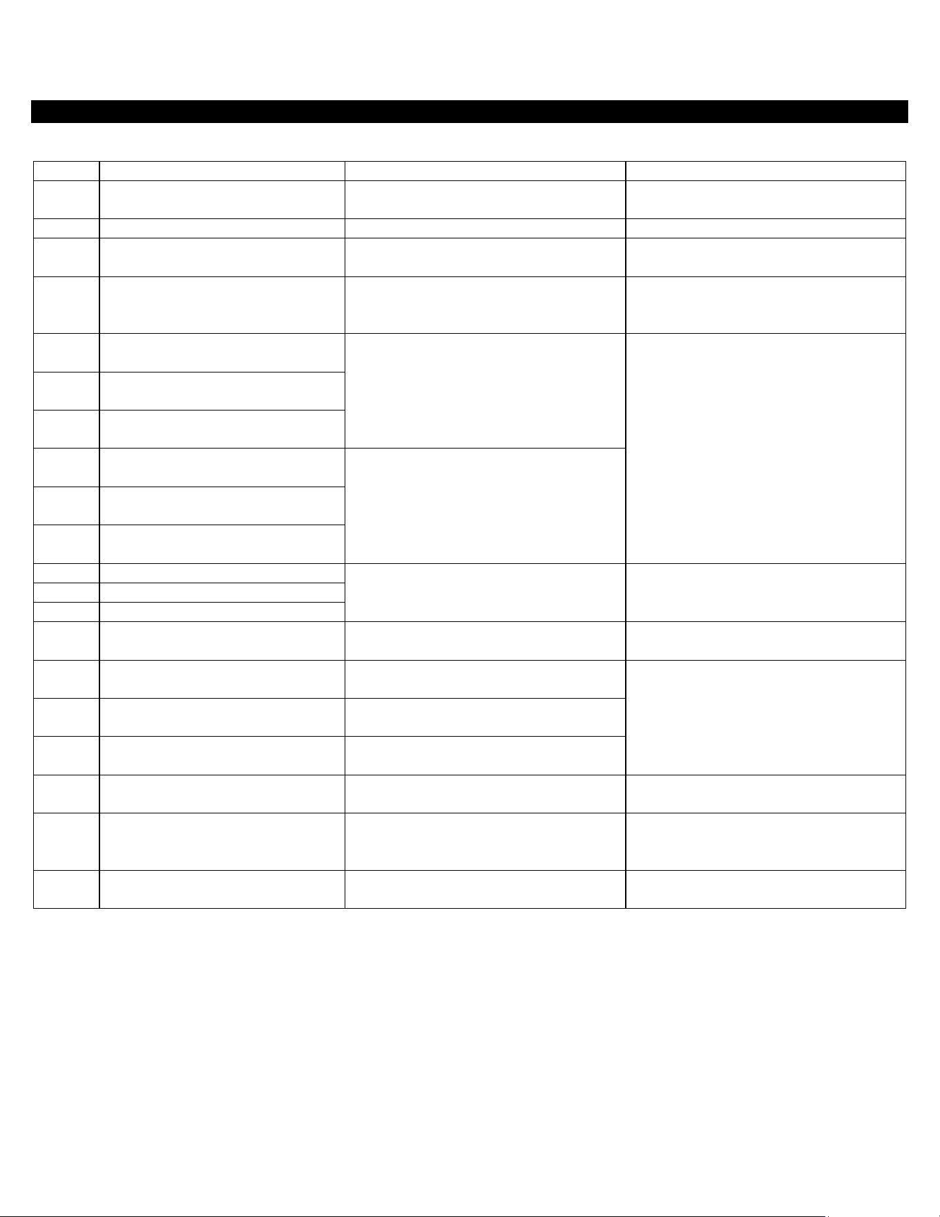
SOFTWARE FEATURES
Notifications:
Code
Name
Unit behavior
Action
B005
Inlet thermistor disconnected
Heating enabled based on default
parameters and history data.
Check thermistor connections. Check
parameter P000 and adjust if needed.
C010
Outlet thermistor disconnected
Heating enabled without calibration.
Check outlet thermistor connection.
B015
Inlet AND outlet thermistors
disconnected
Heating enabled based on default
parameters and history data.
Check thermistor connections. Check
parameter P000 and adjust if needed.
B050
Current transformer disconnected
Heating enabled based on default
parameters. Limited self-diagnostic
capabilities.
Check current transformer connections.
C070
Channel 1 element outside
tolerance, LOW kW rating
Unit runs as intended, attempting to
compensate.
Replace heating element.
C073
Channel 2 element outside
tolerance, LOW kW rating
C076
Channel 3 element outside
tolerance, LOW kW rating
B071
Channel 1 element outside
tolerance, LOW kW rating
Heating disabled on the associated
channel.
B074
Channel 2 element outside
tolerance, LOW kW rating
B077
Channel 3 element outside
tolerance, LOW kW rating
B080
Channel 1 not heating
Heating disabled on the associated
channel.
Check element(s). Check SSR connections.
Check contactor.
B083
Channel 2 not heating
B086
Channel 3 not heating
A090
All channels off
Heating disabled.
Check for tripped ECOs. Check elements.
Check SSR connections. Check contactor.
B105
Inlet temperature 180-200F
Heating disabled while condition is
present.
Check water supply temperature.
B106
Inlet temperature above 200F
Heating disabled. Heating resumes after
condition disappears, with a delay.
B107
Inlet temperature higher than
setpoint
Unit runs as intended.
B110
Outlet temperature too high (>20F
above setpoint)
Heating disabled while condition is
present.
Check elements. Check incoming voltage.
Check SSRs functionality.
C115
Inlet or outlet temperature too low
Unit runs as intended. Heating not
disabled. Unit freezing and damage
possible.
Check water supply temperature. Verify
installation location temperature to be
above freezing point.
D130
Flow too high
Unit runs as intended. Heating not
disabled.
Consider upgrading the unit or reducing
flow.
16
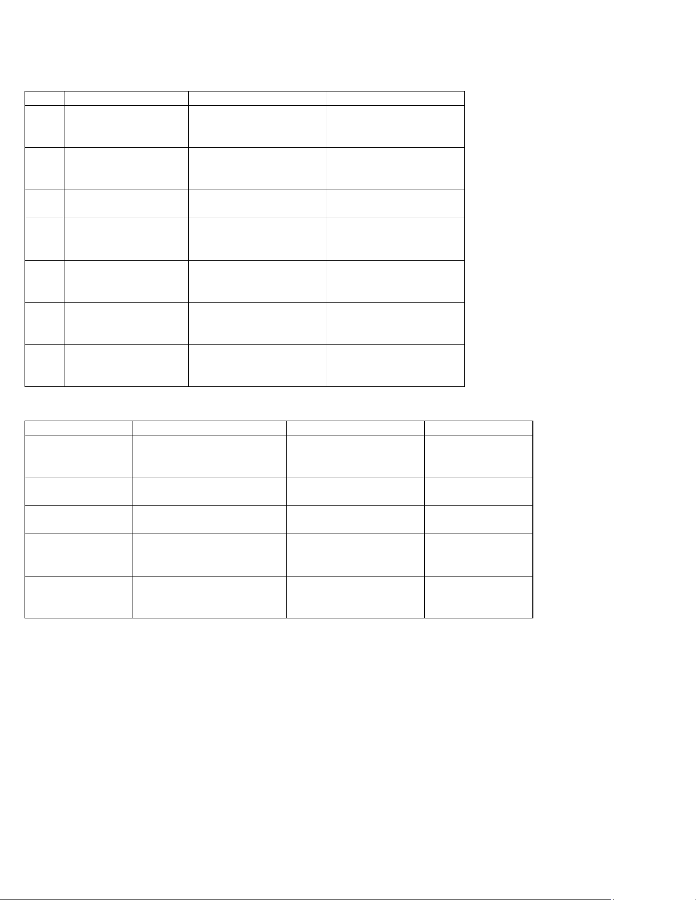
Parameters:
Code
Name
Details
Default/values
P000
Inlet override
Overrides inlet
temperature in case of an
inlet thermistor missing.
180F OR highest measured
inlet temperature.
P005
Setpoint tuning
Allows user to fine tune
outlet temperature to
match the setpoint.
0F (adjustable between -10
and 10 F)
P030
Activation flow
Minimum flow required to
enable heating.
0.5gpm (adjustable
between 0.5 and 10 gpm)
P045
Activation delay
Time between flow above
activation threshold and
heating enabled.
1s (adjustable between 0
and 60 seconds)
P050
Delay contactor off
Time between flow below
activation threshold and
contactor disengaging.
5s (adjustable between 3
seconds and always on)
P051
Delay display off
Time between last user
interaction and display
dimming.
5 minutes (adjustable
between 10 seconds and
always on)
P060
Units selection
Select between metric (C,
lpm) and imperial units (F,
gpm).
F (imperial)
Usage data:
Name
Message displayed
Details
Reset
Gallon counter
Count: nnnnnn.n gal
Volume of water that
passed through the unit
from the last reset.
Yes – hold ENT
Gallons total
Total: nnnnnnnn gal
Total volume of water that
passed through the unit.
No
Hours total
ON: nnnnnn.n hrs
Total number of hours the
unit has been powered on.
No
Heat hours counter
Count: nnnnnn.n hrs
Number of ours the unit
has been actively heating
from the last reset.
Yes – hold ENT
Heat hours total
Total: nnnnnn.n hrs
Total number of hours the
unit has been actively
heating.
No
Note: all parameters are measured only when the unit is powered on and the control system is functional. Where
flow measurement is implied, flow must be above turn on threshold.
17
START-UP PROCESS
Plumbing installation checklist must be filled out and left with water heater. Must flush water heater for 2 minutes at a minimum.
Eemax installation checklist and start-up procedure for ProSeries XTP water heaters
Important - Read and fully understand all steps outlined below before proceeding. Failure to do so may damage the water heater and
void any warranty. Technical support is available at 1 (800) 543-6163
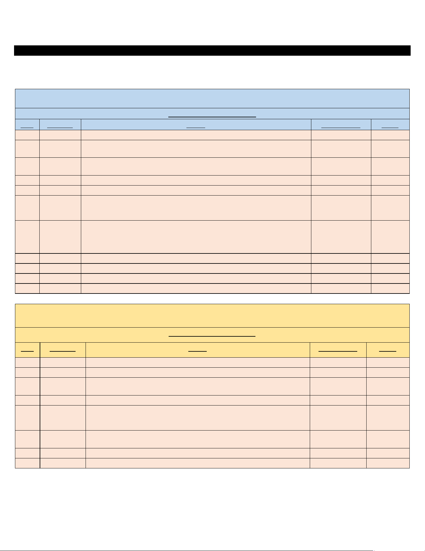
Plumbing installation checklist
Step
Category
Action
Confirmed by
Notes
1
Water
Heater is supplied with clean potable water
2
Water
Plumbing orientation is correct – water connections on the bottom - inlet on the right,
outlet on the left
3
Water
Ensure piping connections are not causing stress or torque on the inlet and outlet
fittings
4
Water
No leaks at water connection or in plumbing network
5
Water
Water pressure is between 40-90 PSI (min 35psi)
6
Water
Long pipe runs, high flow rates and valves closing can cause pressure spikes (water
hammer) above 1000 PSI. Consult piping schematic to ensure arrestors and regulators
are properly sized and located.
7
Water
(with power off) Open supply valves to water heater - run water through fixtures to
purge all air and debris in system. With water flowing, visually inspect the clear
element tubes between the inlet and outlet manifold to ensure no air bubbles are
present. (this may take several minutes)
8
Water
Using a flashlight, visually inspect heating chamber for any signs of leakage
9
Water
Ensure Water Heater will not freeze
10
Water
Ensure all local plumbing codes are met
11
Water
Plumbing installation correct and complete
Important - Read and fully understand all steps outlined below before proceeding. Failure to do so may damage the water heater and
void any warranty. Technical support is available at 1 (800) 543-6163
Electrical installation checklist
Step
Category
Action
Confirmed by
Notes
12
Power
(with power off) - Breaker and disconnect are of proper size and correctly installed
13
Power
(with power off) - Wiring and conduit are of proper size and correctly installed.
14
Power
(with power off) - Wiring connections at terminals are correct orientation, tight, with
no stray wire strands or pinched sheathing
15
Power
(with power off) - Proper ground,(not neutral) is clean, and tight
16
Power
(no water flowing, do not turn it on, close outlet water shut off valve if uncontrolled
environment-left hand side) Apply power - ensure voltage and phasing is according
to model rating
17
Power
Disengage power after voltage and phasing is confirmed (open outlet shutoff valve if
closed during step 14)
18
Power
Ensure all local electrical codes are met
19
Power
Electrical Installation correct and complete

18
Important - Read and fully understand all steps outlined below before proceeding. Failure to do so may damage the water heater and
void any warranty. Technical support is available at 1 (800) 543-6163
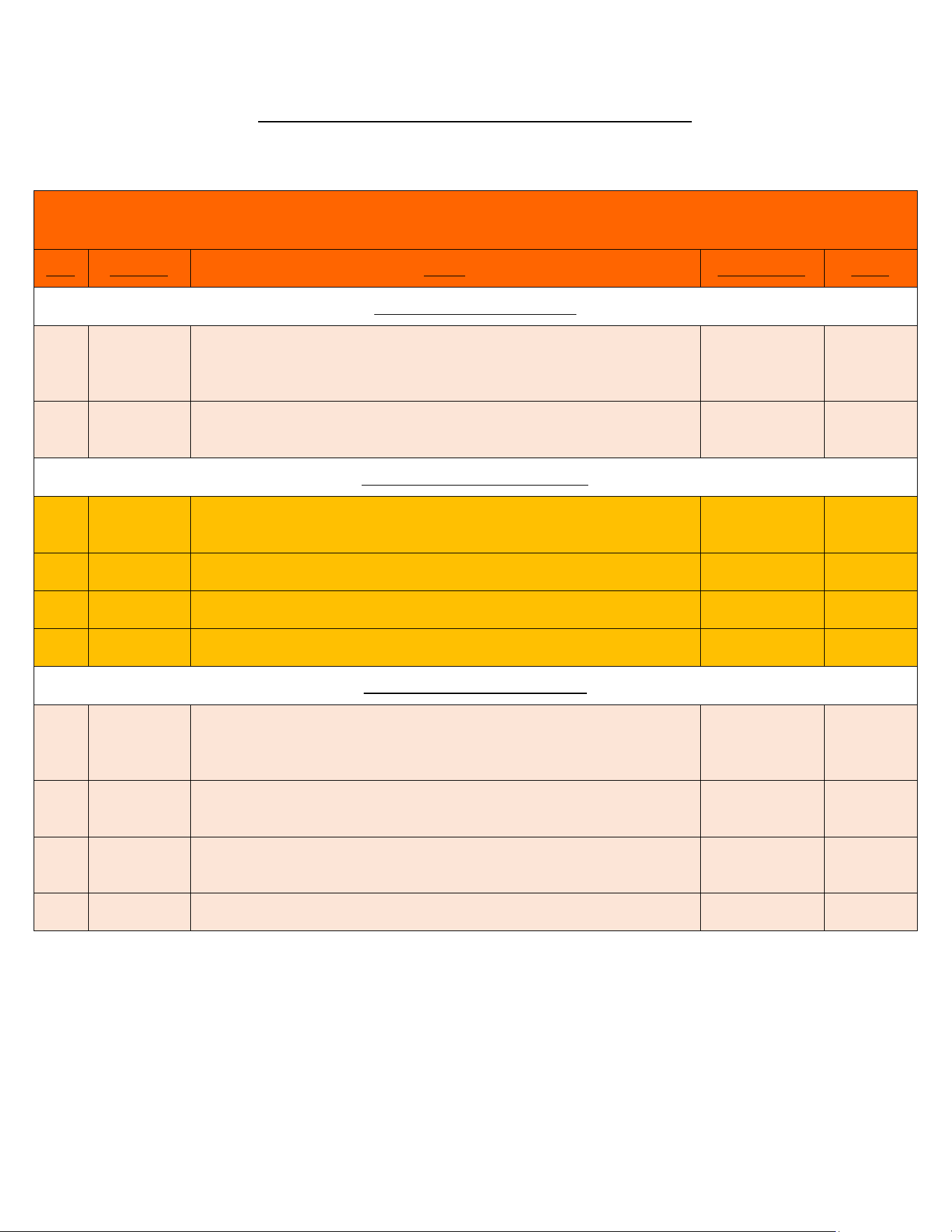
Start-up procedure and checklist
Step
Category
Action
Confirmed by
Notes
20
Start-up
Water requirements (Steps 1-11) are confirmed
21
Start-up
Electrical requirements (Steps 12-19) are confirmed
22
Start-up
Plumbing Codes and Electrical Codes are met and confirmed
23
Start-up
(with power off) Open supply valves to water heater - run water through fixtures to
purge all air and debris in system. With water flowing, visually inspect the clear
element tubes between the inlet and outlet manifold to ensure no air bubbles are
present. (this may take several minutes) Chugging or burping of water is also an
indication of air
24
Start-up
Turn off water flow at all fixtures, keeping water heater supply valves open
25
Start-up
Install and secure the cover of the unit. Apply power to water heater
26
Start-up
Turn water flow on at fixtures
27
Start-up
LCD display board is illuminated
28
Start-up
Contactors engaged (audible click)
29
Start-up
No error codes
30
Start-up
Scroll through display (If display is locked, consult manual for unlock procedure)
31
Start-up
Adjust settings if needed. Note - Keep temperature setting as low as possible for
scald potential and minimizing abuse on the heater.
32
Start-up
Confirm TURN-ON setting meets fixture flow rate
33
Start-up
Confirm SETPOINT setting on display
34
Start-up
Confirm ACTUAL TEMP output on display
35
Start-up
If SETPOINT does not match ACTUAL TEMP then use the TEMPERATURE RISE CHART
in manual along with LOAD%, INLET TEMP and FLOW RATE on display to determine
the maximum theoretical output.
36
Start-up
Shut water flow off at fixture
37
Start-up
Power disengaged (audible)
38
Start-up
Repeat start-up steps 25-28 to ensure proper activation and performance
39
Start-up
Water heater installed correctly and operating as designed
After all steps are completed, the heater is fully installed and ready for use.
19
Shutdown Process (Normal, Emergency, and Long Term)
Shut down procedure
Important - Read and fully understand all steps outlined below before proceeding. Failure to do so may damage the water
heater and void any warranty. Technical support is available at 1 (800) 543-6163
Step
Category
Action
Confirmed By
Notes
Normal Shut Down Procedure
1
Normal
Shut power off to unit in order of sequence - In-door (on-door) disconnect (if
applicable) local disconnect, main breaker - perform lock out procedure per
facilities requirements
2
Normal
Close applicable water valves - Inlet and outlet (water heater will not be
drained)
Emergency Shut Down Procedure
1
Emergency
Shut power off to unit In-door (on door) disconnect (if applicable) or local
disconnect
2
Emergency
Shut water valves off - inlet and outlet (water heater will not be drained)
3
Emergency
Complete lock out procedures per facilities requirements
4
Emergency
Notify all parties involved that water heaters are shut down
Long Term Shut Down Procedure
1
Long Term
Shut power off to unit in order of sequence - Indoor disconnect (if applicable)
local disconnect, main breaker - perform lock out procedure per facilities
requirements
2
Long Term
Close applicable water valves - Inlet and outlet (water heater will not be
drained)
3
Long Term
Drain water heater through plumbing network, run compressed air through
the water heater to ensure the heater is completely drained
4
Long Term
Lock out all applicable water valves per facilities procedures

20
MONITORING & PREVENTIVE MAINTENANCE
Recommended routine instrument readings and operation checking: Please note the instrument readings are performed during
water heater operation. No readings are required when the unit is not being used. Check the following readings on the display and
ensure proper performance:
Inlet temperature
Temperature set point
Outlet temperature
Flow rate (GPM)
Notifications
Early warning signs of developing operational or equipment problems:
Based on the measured readings above, the water heater appears to be performing properly however there are notifications.
Displayed flow rate (GPM) appears to be lower than expected
Procedures for handling non-routine problems such as alarms, power failure, and component failure:
No alarms are built into the unit
Power failure will result in a non-operable system – restore power and start-up unit per Start up process
Component failure will result in repeat notifications. Refer to SOFTWARE FEATURES section for notification codes and
corrective action
Preventative maintenance requirements (PMR): Preventive maintenance requirements may impact other items of the installation
such as electrical supply and wiring, water piping and associated valves and controls.
Eemax water heaters are very low maintenance.
Ensure that the water heater is supplied with a clean potable, consistent water supply as outlined in the manual.
Check filter screen or associated y-strainer or other pre-filters to ensure clear water supply within listed water pressure. Ensure proper
electrical supply as outlined within the manual.
Perform PMR per site requirements not to exceed 90 days.
Maintenance inspection program (MIP): Eemax water heaters are very low maintenance. Ensure PMR is completed every 90 days.
Disable power to the unit via external disconnect or local disconnects. Per site lockout procedures open cabinet door and visually
inspect components for sings of damage associated with possible water leaks, excessive heat or external factors that could impact the
water heater and associated components.
Perform MIP per site requirements not to exceed 90 days.
21
TECHNICAL SUPPORT
TECHNICAL SUPPORT FORM
PERFORM STEPS BELOW BEFORE CALLING TECHNICAL SUPPORT
WATER HEATER
MODEL # ____________________________________ SERIAL # ____________________________________
Inlet Water Pressure ____________________ Inlet Water Temperature ____________________
Notifications ______________________________________________________________________________________________
______________________________________________________________________________________________
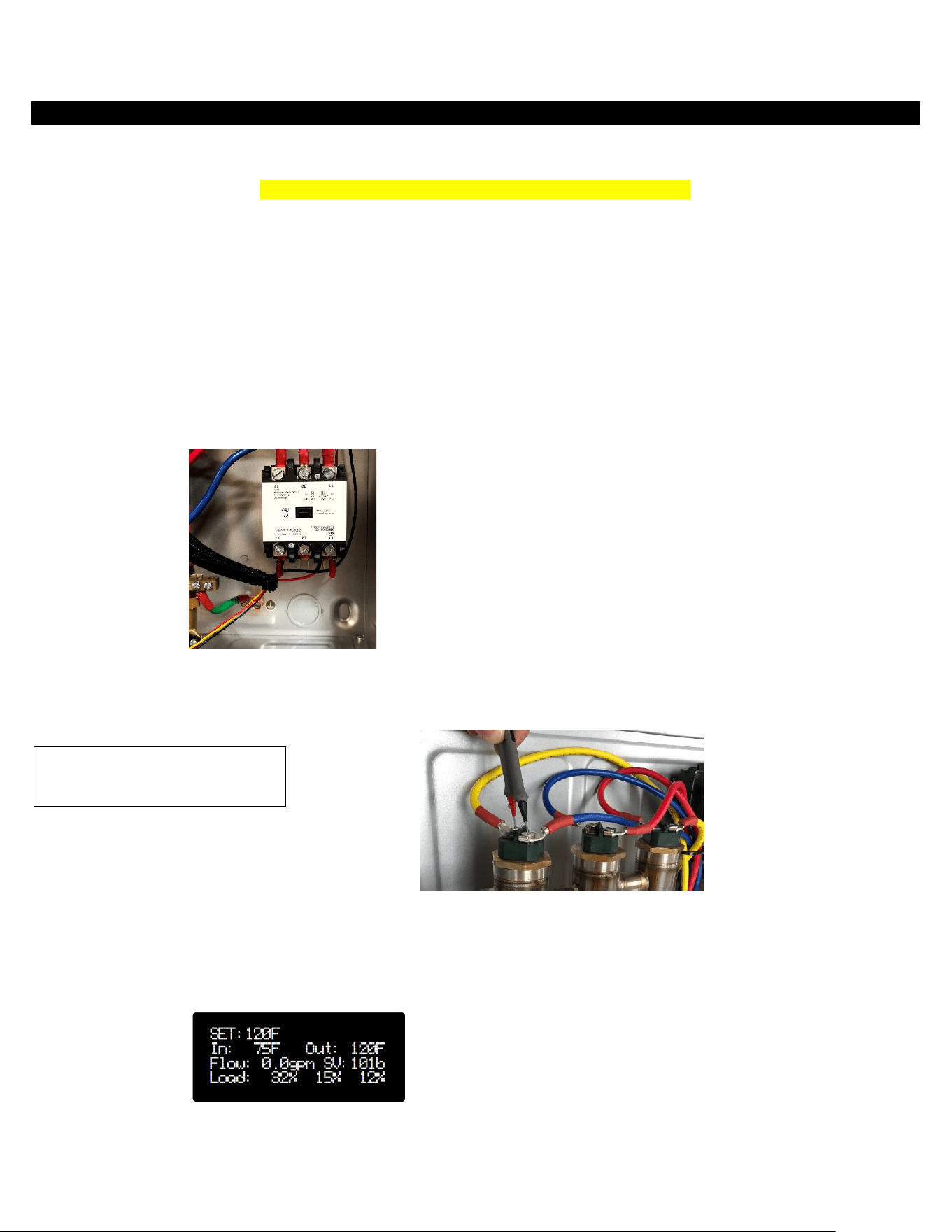
Incoming Voltage
(FIG 1)
L1 ____________
L2 ____________
L3 ____________
Testing Elements
Amp draw on each heating element, Record current
values from display during operation.
EB1 ______ EB2 ______ EB3 ______
Testing Elements (fig 2)
Ohm out heating elements:
E1 ____Ω E2 ____ Ω E3 ____ Ω
E4 ____ Ω E5 ____ Ω E6 ____ Ω
GPM FLOW RATE _____________
LOAD PERCENTAGE (1): _____________
LOAD PERCENTAGE (2): _____________
LOAD PERCENTAGE (3): _____________
FIG 2
FIG 1
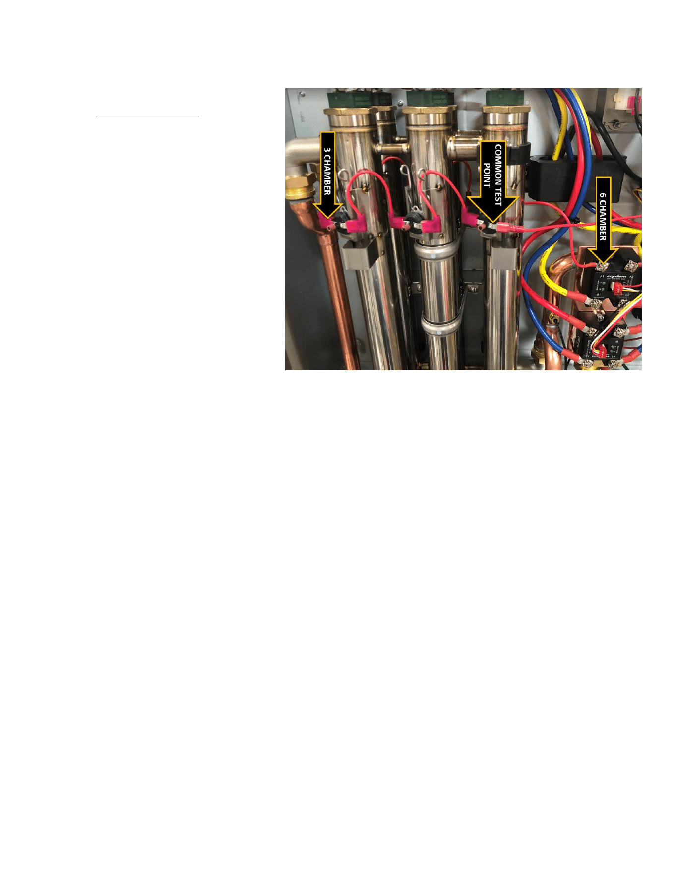
22
ECO Testing Points
Test ECO’s (electric cut offs):
To check all ECO’S simultaneously measure from
COMMON TEST POINT to 3 CHAMBER (or 6
CHAMBER) for continuity. If no continuity, then
check across each ECO individually.
ECO’s may be manually reset after they have cooled.
Run cold water and press the stem to reset. Water
may need to run for a few minutes. Check continuity
to confirm a reset ECO.
23
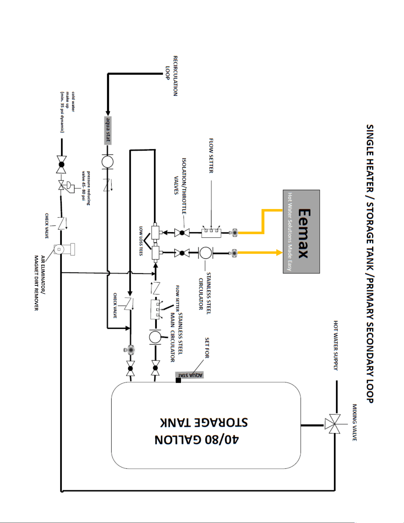
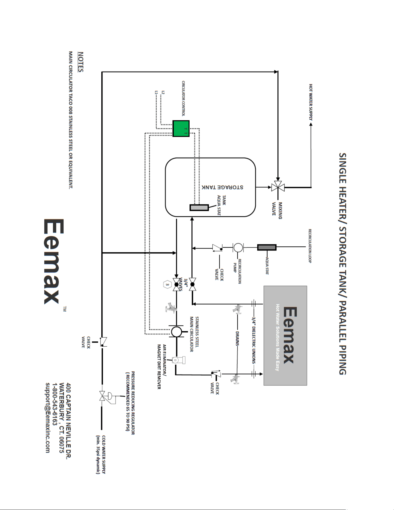
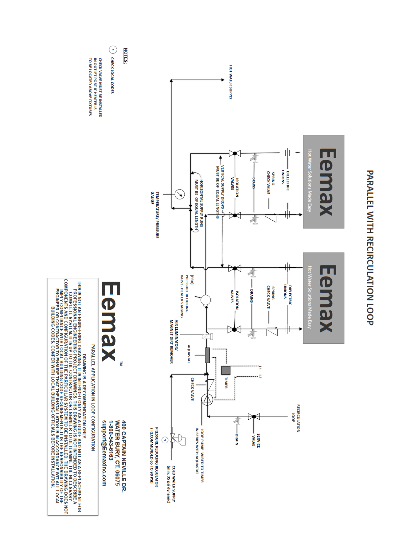
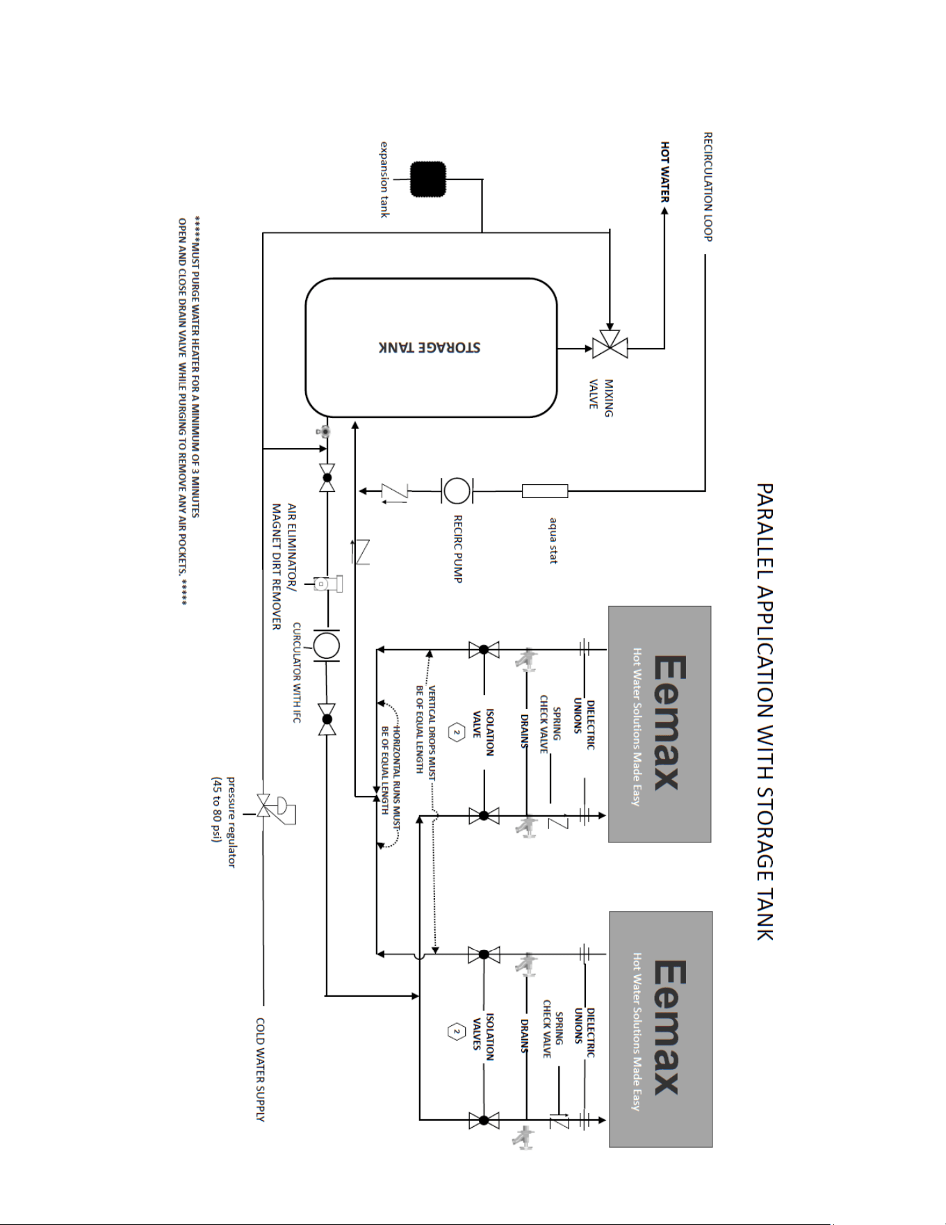
APPLICATIONS SCHEMATICS
24
25
26
27
28
29
30
31
32
33
34
35
36
37
REPAIRS
Repair Parts
WARNING
Service and repairs are to be performed by licensed electricians or qualified
servicemen.
WARNING
Before attempting any repairs to the heater, make sure that the electrical breaker is
“off” and confirm that there is no voltage at the heater.
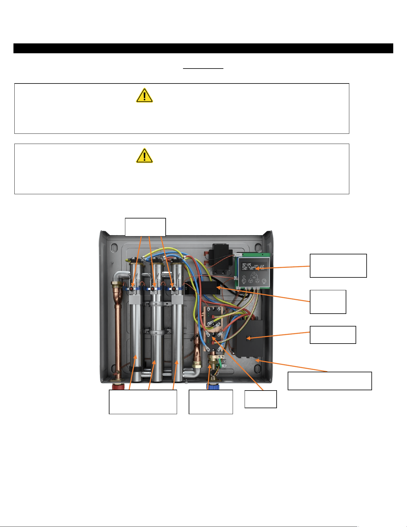
p
* HEATING ELEMENT ASSEMBLY CONSISTS OF ONE HEATER CORE AND WIRE ELEMENT(S)
** FLOW METER KIT CONSISTS OF PADDLE WHEEL, DOWEL PIN, O RING AND 4 MOUNTING SCREWS.
ECO’s
Electrical Connections
LED Display &
Control Board
Current
Sensor
Contactor
Heating Element
Assembly*
Flow
Meter **
SSR’s
38
Repair Parts (continued)
Model Number
Element
Number
Assembly
Flow Meter
Assembly
(inc board)
Master
Display
Board
Transformer
Inlet & Outlet
Thermistors
SSR
ECO
Assembly
Contactor
Inlet
Manifold Kit
Outlet
Manifold Kit
Inlet Fitting
Flow Meter
Kit
XTP018208 EX05502-00 EX76042-02 EX09100-01 EX08303-07
EX08200-16 &
EX08200-17
EX08200-12 EX279D EX08309-02 EX78016-00 EX78017-00 EX78018-00
XTP024208 EX05502-01 EX76042-02 EX09100-01 EX08303-07
EX08200-16 &
EX08200-17
EX08200-12 EX279D EX08100-11 EX78016-00 EX78017-00 EX78018-00
XTP032208 EX05502-02 EX76042-02 EX09100-01 EX08303-07
EX08200-16 &
EX08200-17
EX08200-12 EX279D EX08100-10 EX78016-00 EX78017-00 EX78018-00
XTP016480 EX05502-03 EX76042-02 EX09100-01 EX08303-08
EX08200-16 &
EX08200-17
EX08200-12 EX279D EX08309-02 EX78016-00 EX78017-00 EX78018-00
XTP020480 EX05502-04 EX76042-02 EX09100-01 EX08303-08
EX08200-16 &
EX08200-17
EX08200-12 EX279D EX08309-02 EX78016-00 EX78017-00 EX78018-00
XTP024480 EX05502-05 EX76042-02 EX09100-01 EX08303-08
EX08200-16 &
EX08200-17
EX08200-12 EX279D EX08309-02 EX78016-00 EX78017-00 EX78018-00
XTP027480 EX05502-06 EX76042-02 EX09100-01 EX08303-08
EX08200-16 &
EX08200-17
EX08200-12 EX279D EX08309-02 EX78016-00 EX78017-00 EX78018-00
XTP036480 EX05502-07 EX76042-02 EX09100-01 EX08303-08
EX08200-16 &
EX08200-17
EX08200-12 EX279D EX08309-02 EX78016-00 EX78017-00 EX78018-00
XTP048480 HA-P004 EX76042-02 EX09100-01 EX08303-08
EX08200-16 &
EX08200-17
EX08200-12 EX279D EX08306-00 EX78016-00 EX78017-00 EX78018-00
XTP054480 HA-P005 EX76042-02 EX09100-01 EX08303-08
EX08200-16 &
EX08200-17
EX08200-12 EX279D EX08306-00 EX78016-00 EX78017-00 EX78018-00
45
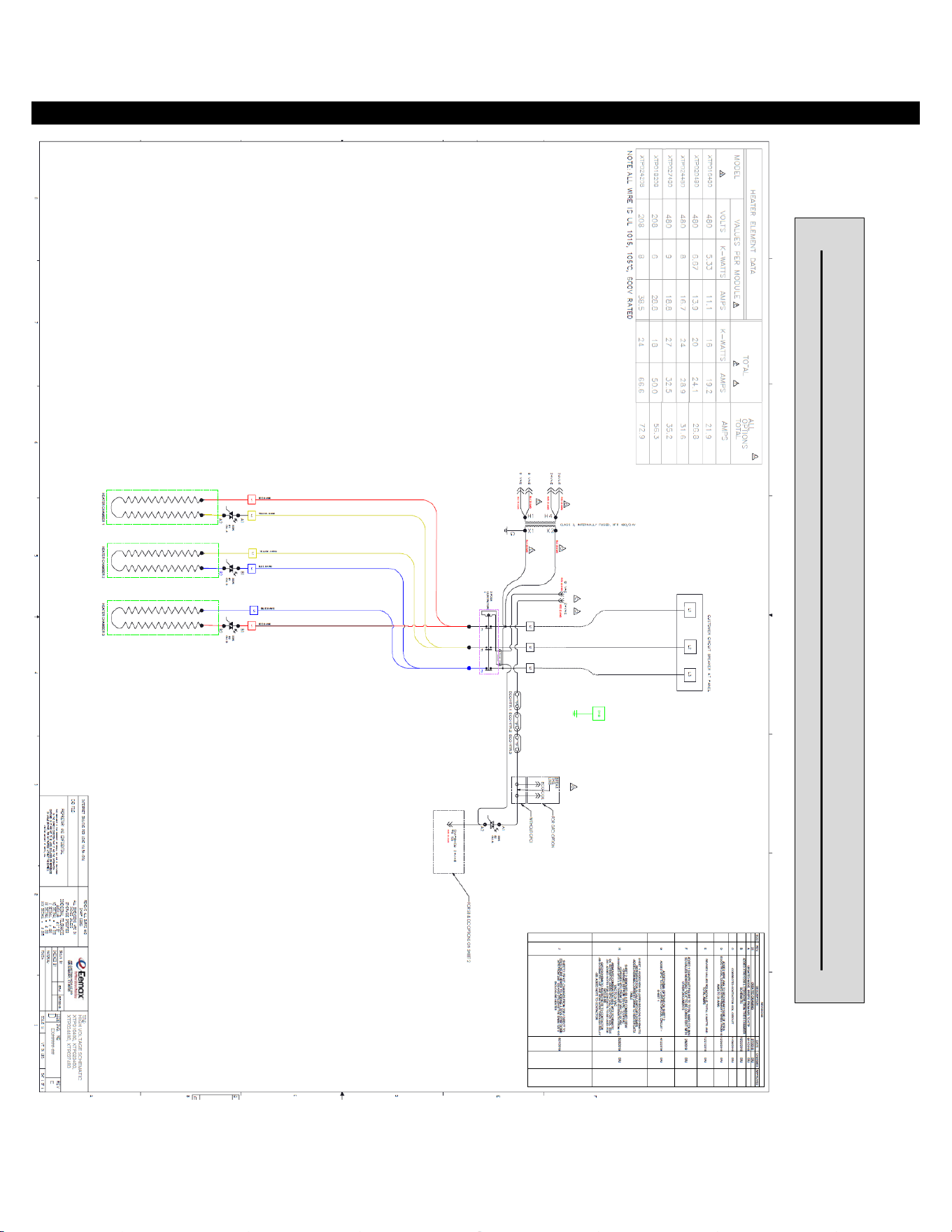
39
WIRING SCHEMATICS
XTP016480
-
027480 & XTP018208
-
024208 WIRING SCHEMATIC
EX07200-89 REV A
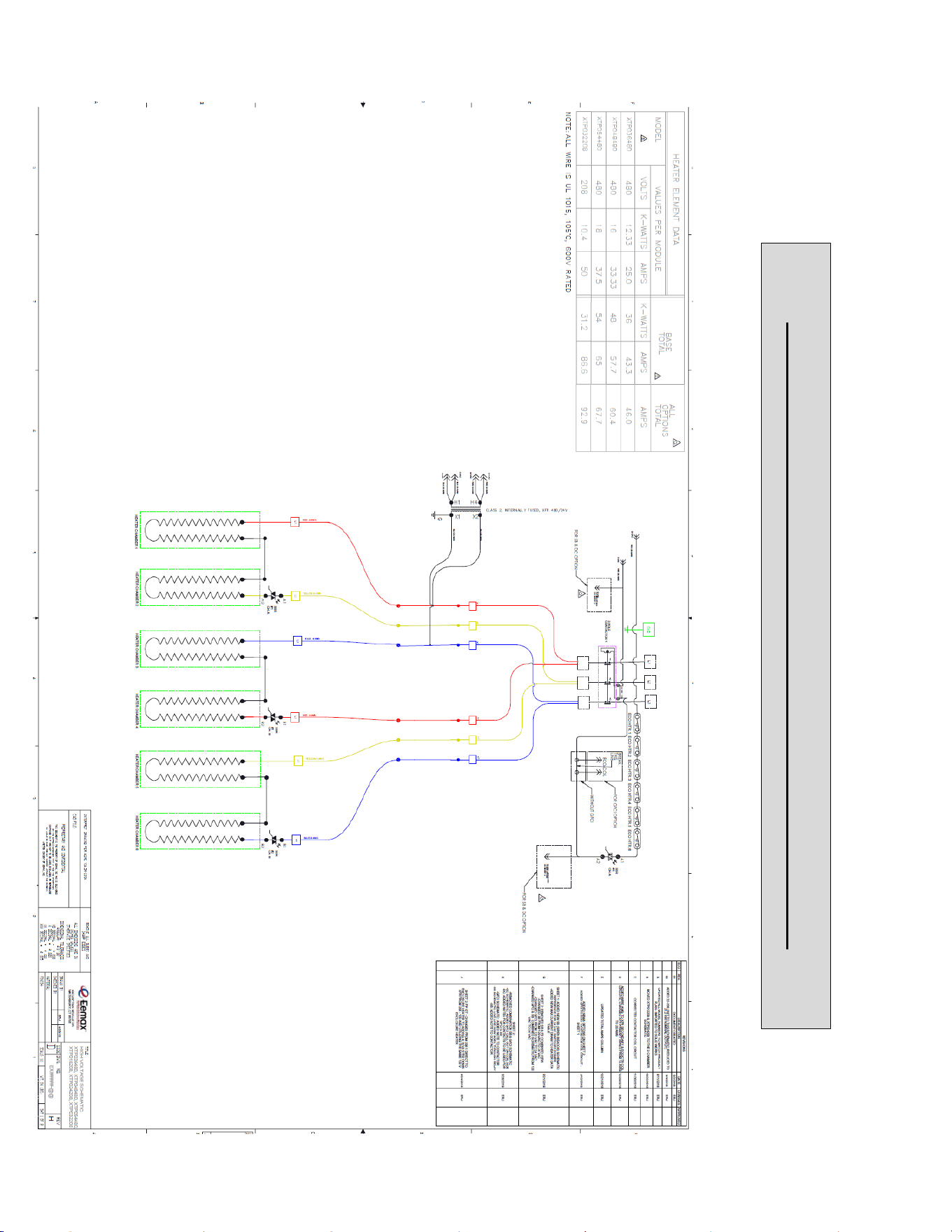
40
XTP0
36
480
-
0
54
480 & XTP0
32
208
WIRING SCHEMATIC

EX07200-89 REV A
41
USA AND CANADA:
Eemax Inc.
400 Captain Neville Drive, Waterbury, CT 06705
Toll Free: 1-800-543-6163, or 203-267-7890 Fax: 203-267-7975
Eemax.Support@eemax.com

