Service Manual
Number: 73252
Issued: 4-30-2024
hoshizakiamerica.com
Modular Crescent Cuber
Models
KMD-505MAJ, MWJ, MRJZ
KMD-705MAJ, MWJ, MRJZ
2
WARNING
Only qualied service technicians should install and service the appliance.
To obtain the name and phone number of your local Hoshizaki Certied Service
Representative, visit www.hoshizakiamerica.com. No service should be undertaken
until the technician has thoroughly read this Service Manual. Failure to service and
maintain the appliance in accordance with this manual will adversely affect safety,
performance, component life, and warranty coverage. Proper installation is the
responsibility of the installer. Product failure or property damage due to improper
installation is not covered under warranty.
Hoshizaki provides this manual primarily to assist qualied service technicians in the
service of the appliance.
Should the reader have any questions or concerns which have not been satisfactorily
addressed, please call, send an e-mail message, or write to the Hoshizaki Technical
Support Department for assistance.
Phone: 1-800-233-1940; (770) 487-2331
Fax: 1-800-843-1056; (770) 487-3360
E-mail: techsuppor[email protected]
618 Highway 74 South
Peachtree City, GA 30269
Attn: Hoshizaki Technical Support Department
NOTE: To expedite assistance, all correspondence/communication MUST include the
following information:
• Model Number
• Serial Number
• Complete and detailed explanation of the problem.

3
CONTENTS
Important Safety Information ................................................................................................. 5
I. Construction and Water/Refrigeration Circuit Diagrams ..................................................... 7
A. Construction .................................................................................................................. 7
1. Air-Cooled Models (MAJ) ......................................................................................... 7
2. Water-Cooled Models (MWJ) ................................................................................... 8
3. Remote Models (MRJZ ) ......................................................................................... 9
B. Water/Refrigeration Circuit Diagrams .......................................................................... 10
1. Air-Cooled Models (MAJ) ....................................................................................... 10
2. Water-Cooled Models (MWJ) ..................................................................................11
3. Remote Models (MRJZ) ........................................................................................ 12
II. Sequence of Operation and Service Diagnosis ............................................................... 13
A. Sequence of Operation Flow Charts ........................................................................... 13
1. Operation Flow Chart ............................................................................................ 13
2. Shutdown Flow Chart ............................................................................................ 14
B. Service Diagnosis ....................................................................................................... 15
C. Control Board Check ................................................................................................... 22
D. Bin Control Check and Adjustment .............................................................................. 24
1. Ultrasonic Bin Control Check ................................................................................. 24
2. Ultrasonic Bin Control Adjustment ......................................................................... 26
E. Float Switch Check and Cleaning ............................................................................... 29
F. Thermistor Check ......................................................................................................... 31
G. Control Switch ............................................................................................................. 31
H. Mode Switch ............................................................................................................... 31
I. Diagnostic Tables .......................................................................................................... 32
J. Freeze-Up Check List .................................................................................................. 36
III. Controls and Adjustments ............................................................................................... 37
A. Control Board Layout .................................................................................................. 38
B. LED Lights and Audible Alarm Safeties ....................................................................... 39
C. Settings and Adjustments ............................................................................................ 40
1. Default Dip Switch Settings .................................................................................... 40
2. Harvest Time (S4 dip switch 1 & 2)........................................................................ 41
3. Pump-Out Time/Harvest Time During Pump-Out (S4 dip switch 3 & 4) ................. 41
4. Pump-Out Frequency Control (S4 dip switch 5) ..................................................... 42
5. Harvest Pump Time (Harvest Assist) (S4 dip switch 6) ......................................... 42
6. Harvest Pump Time (Harvest Assist (S4 dip switch 7)) ......................................... 43
7. Factory Use (S4 dip switch 8)................................................................................. 43
8. Freeze Timer (S4 dip switch 9 & 10) ...................................................................... 43
9. Float Switch Selector (S5 dip switch 1) ................................................................. 44
10. Rell Counter (S5 dip switch 2 and 3) .................................................................. 44
11. Minimum Harvest Time (S5 dip switch 4) ............................................................. 44
12. Anti-Slush (S5 dip switch 5) ................................................................................. 45
IMPORTANT
This manual should be read carefully before the appliance is serviced. Read
the warnings and guidelines contained in this manual carefully as they provide
essential information for the continued safe use, service, and maintenance of the
appliance. Retain this manual for any further reference that may be necessary.

4
IV. Refrigeration Circuit and Component Service Information.............................................. 46
A. Refrigeration Circuit Service Information .................................................................... 46
B. Component Service Information .................................................................................. 49
C. Water Regulating Valve Adjustment (water-cooled model) .......................................... 49
V. Maintenance .................................................................................................................... 50
VI. Preparing the Appliance for Periods of Non-Use ............................................................ 51
VII. Disposal ......................................................................................................................... 53
VIII. Technical Information .................................................................................................... 54
A. Specication and Performance Data Sheets ............................................................... 54
1. KMD-505MAJ ......................................................................................................... 54
2. KMD-505MWJ ....................................................................................................... 55
3. KMD-505MRJZ with URC-5FZ .............................................................................. 56
4. KMD-705MAJ ........................................................................................................ 57
5. KMD-705MWJ ....................................................................................................... 58
6. KMD-705MRJZ with URC-9FZ .............................................................................. 59
B. Wiring Diagram ............................................................................................................ 60
5
Important Safety Information
Throughout this manual, notices appear to bring your attention to situations which could
result in death, serious injury, damage to the appliance, or damage to property.
WARNING Indicates a hazardous situation which could result in death or
serious injury.
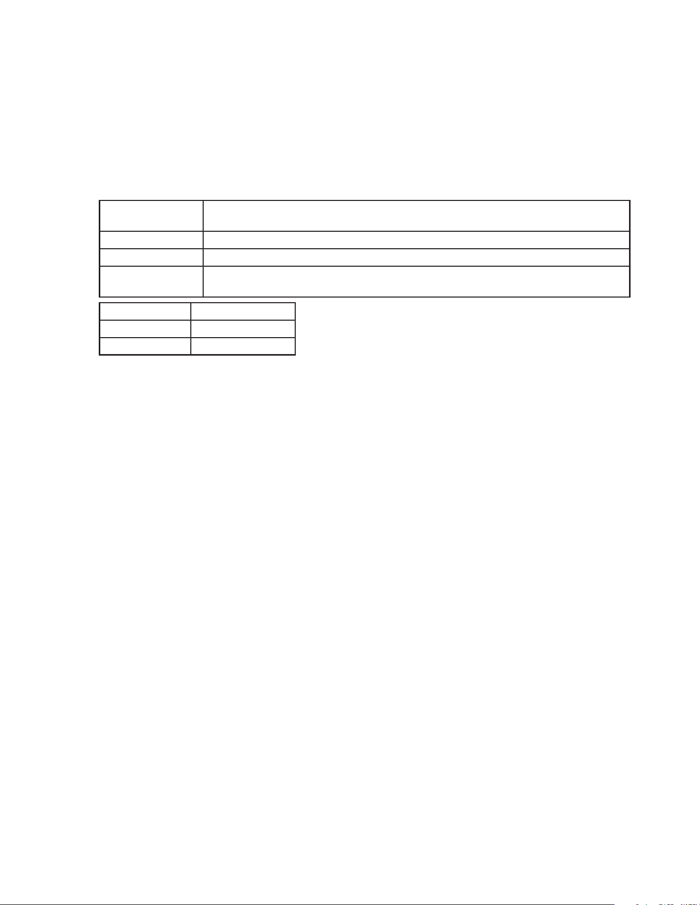
NOTICE Indicates a situation which could result in damage to the
appliance or property.
IMPORTANT Indicates important information about the use and care of the
appliance.
WARNING
The appliance should be destined only to the use for which it has been expressly
conceived. Any other use should be considered improper and therefore dangerous.
The manufacturer cannot be held responsible for injury or damage resulting from
improper, incorrect, and unreasonable use. Failure to service and maintain the
appliance in accordance with this manual will adversely affect safety, performance,
component life, and warranty coverage and may result in costly water damage.
To reduce the risk of death, electric shock, serious injury, or re, follow basic
precautions including the following:
• Only qualied service technicians should install and service this appliance.
• The appliance must be installed in accordance with applicable national, state, and
local codes and regulations.
• Electrical connection must be hard-wired and must meet national, state, and local
electrical code requirements. Failure to meet these code requirements could result
in death, electric shock, serious injury, re, or severe damage to equipment.
• The icemaker requires an independent power supply of proper capacity. See the
nameplate for electrical specications. Failure to use an independent power supply
of proper capacity can result in a tripped breaker, blown fuses, damage to existing
wiring, or component failure. This could lead to heat generation or re.
• THE ICEMAKER MUST BE GROUNDED. Failure to properly ground the icemaker
could result in death or serious injury.
• Move the control switch to the "OFF" position and turn off the power supply before
servicing. Lockout/Tagout to prevent the power supply from being turned back on
inadvertently.
• To reduce the risk of electric shock, do not touch the control or mode switch with
damp hands.
• Do not make any alterations to the unit. Alterations could result in electric shock,
injury, re, or damage to the unit.
• The appliance is not intended for use by persons (including children) with reduced
physical, sensory, or mental capabilities, or lack of experience and knowledge,
unless they have been given supervision or instruction concerning use of the
appliance by a person responsible for their safety.
6
WARNING, continued
• Children should be properly supervised around this appliance.
• Do not climb, stand, or hang on the appliance or allow children or animals to do so.
Serious injury could occur or the appliance could be damaged.
• Do not use combustible spray or place volatile or ammable substances near the
appliance. They might catch re.
• Keep the area around the appliance clean. Dirt, dust, or insects in the appliance
could cause harm to individuals or damage to the appliance.
Additional Warning for Remote Models
• THE REMOTE CONDENSER UNIT MUST BE GROUNDED. The power supply and
ground connection to the remote condenser unit are supplied from the icemaker.
Failure to properly ground the remote condenser unit could result in death or
serious injury.
• Move the icemaker control switch to the "OFF" position and turn off the power
supply to the icemaker before servicing the remote condenser unit.
Lockout/Tagout to prevent the power supply from being turned back on
inadvertently.
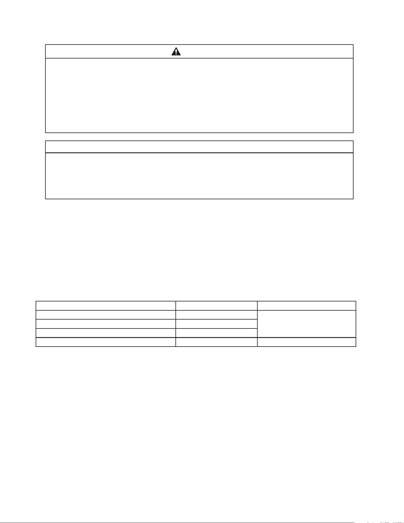
NOTICE
• Follow the instructions in this manual carefully to reduce the risk of costly water
damage.
• In areas where water damage is a concern, install in a contained area with a oor
drain.
• Install the appliance in a location that stays above freezing. Normal operating
ambient temperature must be within 45°F to 100°F (7°C to 38°C).
• Do not leave the icemaker on during extended periods of non-use, extended
absences, or in sub-freezing temperatures. To properly prepare the icemaker for
these occasions, follow the instructions in "VI. Preparing the Appliance for Periods
of Non-Use."
• Do not place objects on top of the appliance.
• The dispenser unit/ice storage bin is for ice use only. Do not store anything else in
the dispenser unit/ice storage bin.
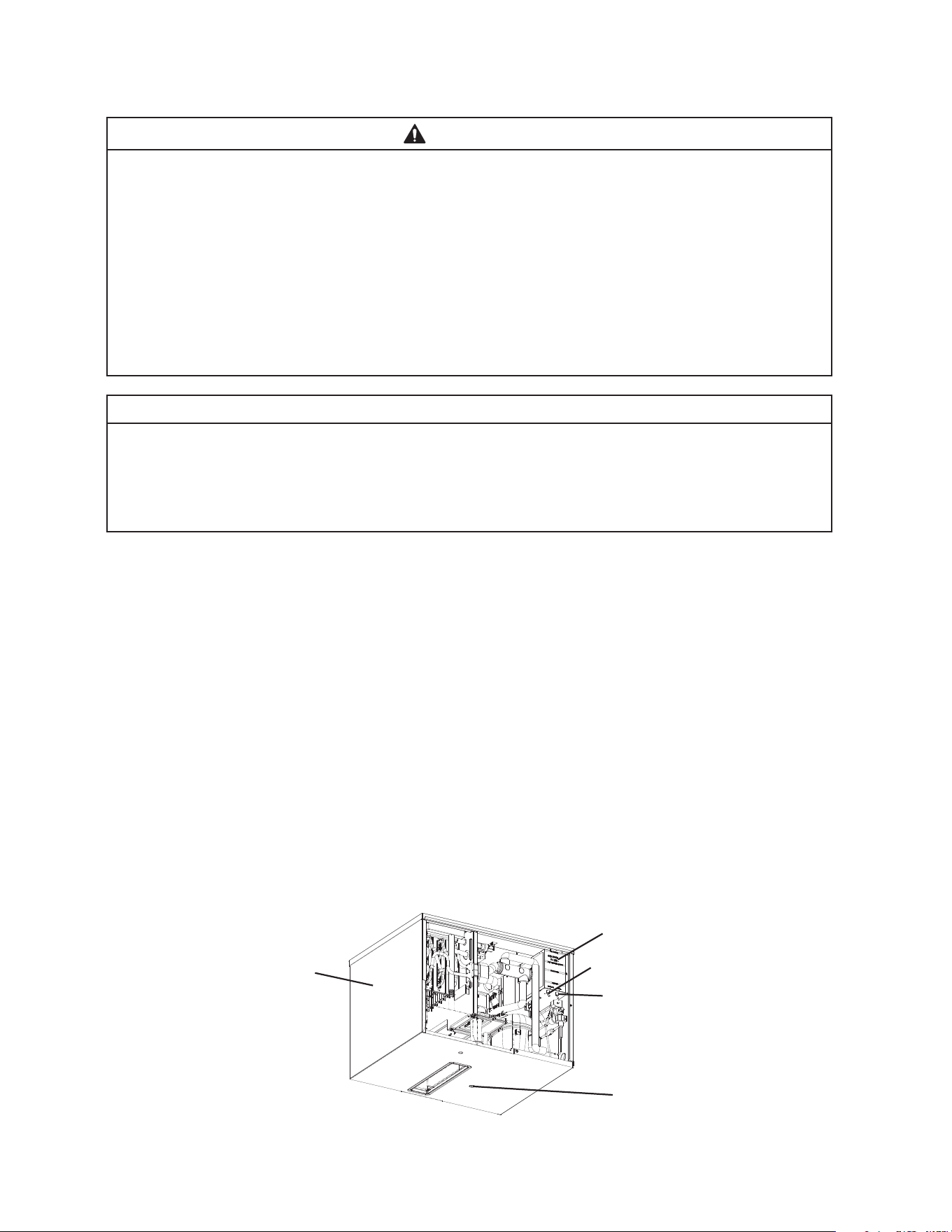
7
I. Construction and Water/Refrigeration Circuit Diagrams
A. Construction
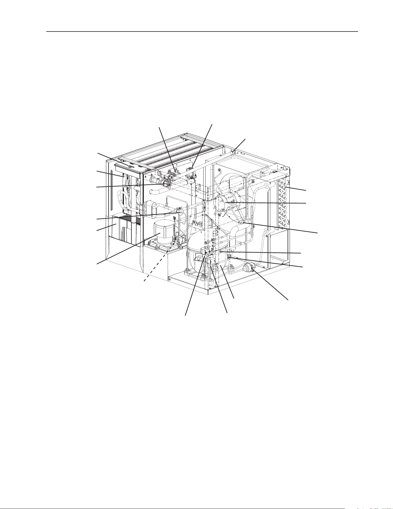
1. Air-Cooled Models (MAJ)
Model Shown: KMD-505MAJ
Water Supply Inlet
Condenser
Drier
Spray Tube
Water Pump
Float Switch
Compressor
Thermostatic
Expansion Valve
Fan Motor
Hot Gas Valve
Cleaning Valve
Ultrasonic
Bin Control
Sensor
Inlet Water Valve
High-Pressure
Switch
Evaporator
Strainer
Drain Valve
Liquid Line Valve
Cube Guide
8
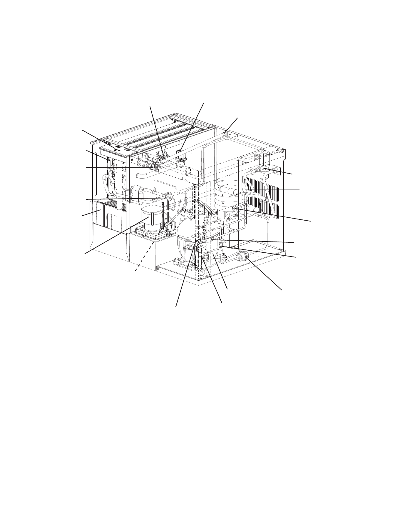
2. Water-Cooled Models (MWJ)
Water Regulating
Valve
Model Shown: KMD-505MWJ
Water Supply Inlet
Condenser
Drier
Spray Tube
Water Pump
Float Switch
Compressor
Thermostatic
Expansion Valve
Hot Gas Valve
Cleaning Valve
Ultrasonic
Bin Control
Sensor
Inlet Water Valve
High-Pressure
Switch
Evaporator
Strainer
Drain Valve
Liquid Line Valve
Cube Guide
9
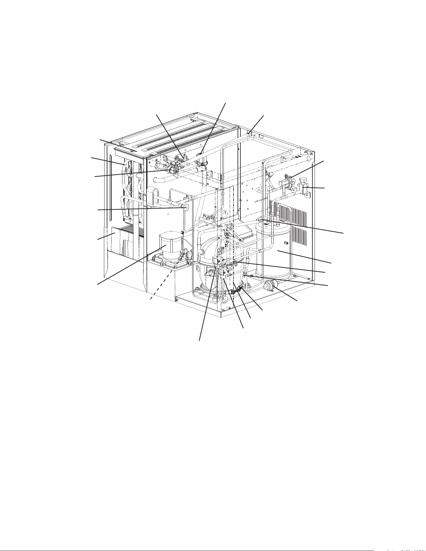
3. Remote Models (MRJZ )
Receiver Tank
Model Shown: KMD-705MRJZ
Crankcase Heater
Discharge
Shut Off Valve
Water Supply Inlet
Drier
Spray Tube
Water Pump
Float Switch
Compressor
Thermostatic
Expansion Valve
Hot Gas Valve
Cleaning Valve
Ultrasonic
Bin Control
Sensor
Inlet Water Valve
High-Pressure
Switch
Evaporator
Strainer
Drain Valve
Liquid Line Valve
Cube Guide
Liquid Line
Shut Off Valve
10
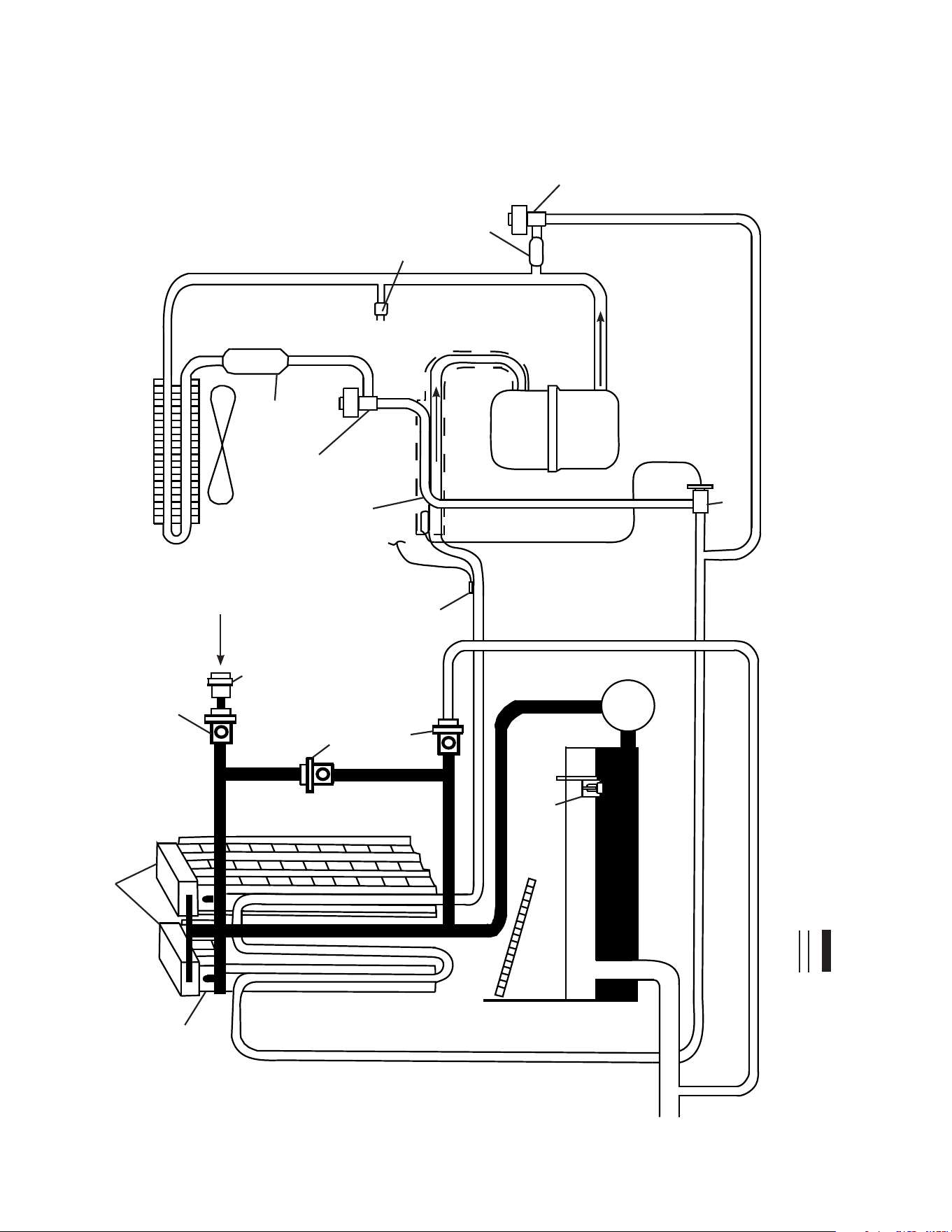
B. Water/Refrigeration Circuit Diagrams
1. Air-Cooled Models (MAJ)
Water Supply
Float Switch
Drain
Thermostatic Expansion Valve
Compressor
Hot Gas
Valve
High-Pressure
Switch
Strainer
Fan
Drier
Condenser
Evaporator
Discharge Line
Suction Line
Water Pump
Thermistor
Spray Tubes
Inlet Water Valve
Water Tank
Refrigeration Circuit
Water Circuit
Heat
Exchanger
Liquid Line Valve
Cleaning Valve
Drain Valve
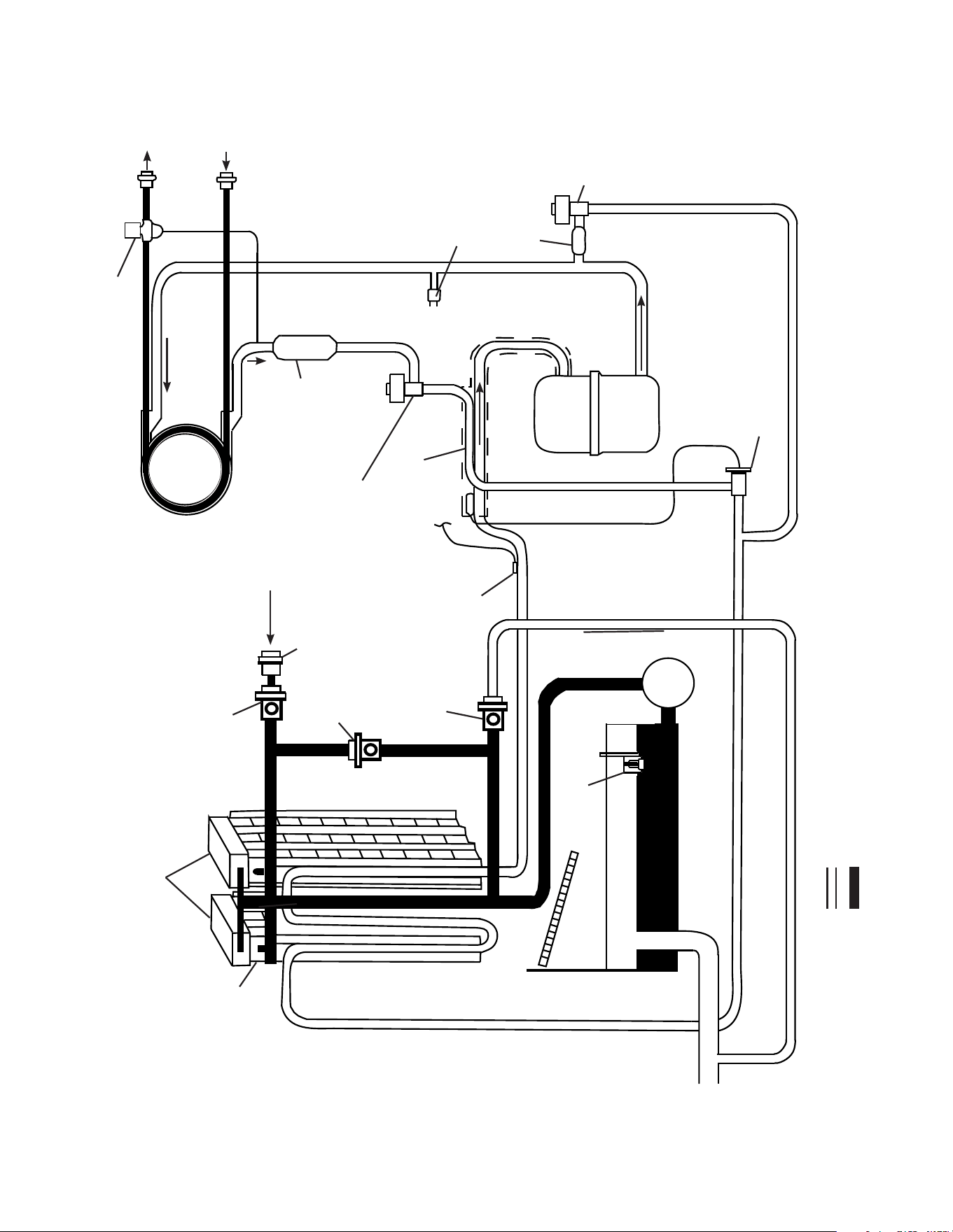
11
2. Water-Cooled Models (MWJ)
Water Supply
Float Switch
Drain
Thermostatic Expansion Valve
Compressor
Hot Gas
Valve
High-Pressure
Switch
Strainer
Drier
Condenser
Evaporator
Discharge Line
Suction Line
Water Pump
Thermistor
Spray Tubes
Inlet Water Valve
Water Tank
Refrigeration Circuit
Water Circuit
Heat
Exchanger
Liquid Line Valve
Water Regulating Valve
Cleaning Valve
Drain Valve
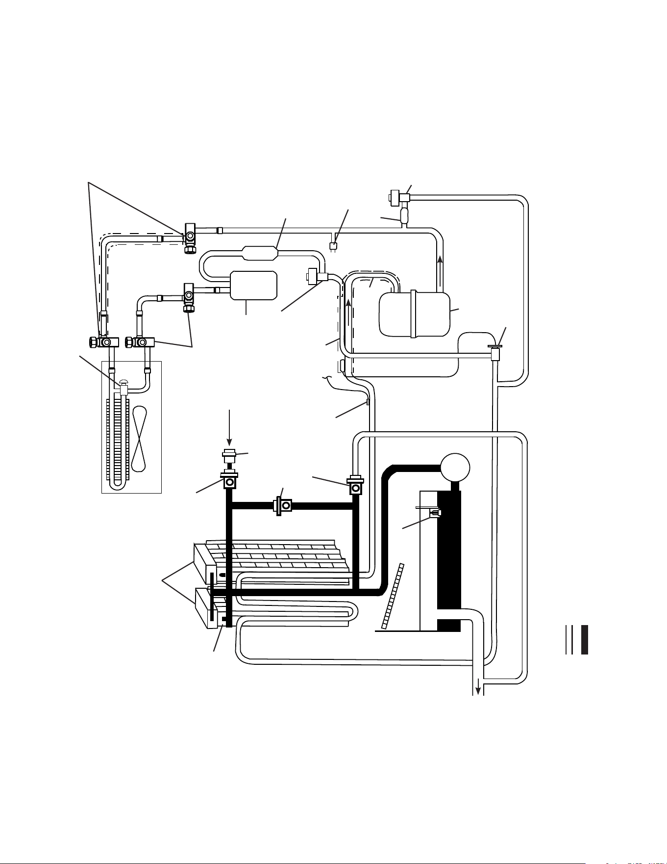
12
3. Remote Models (MRJZ)
Water Supply
Float Switch
Drain
Compressor
Hot Gas
Valve
High-Pressure
Switch
Strainer
Fan
Drier
Remote Condenser
Evaporator
Discharge Line
Suction Line
Water Pump
Thermistor
Spray Tubes
Inlet Water Valve
Water Tank
Refrigeration Circuit
Water Circuit
Liquid Line
Valve
Receiver
Headmaster
(C.P.R.)
Thermostatic Expansion
Valve
Heat
Exchanger
Cleaning Valve
Drain Valve
Discharge Line
Shutoff Valves
Liquid Line
Shutoff Valves
13
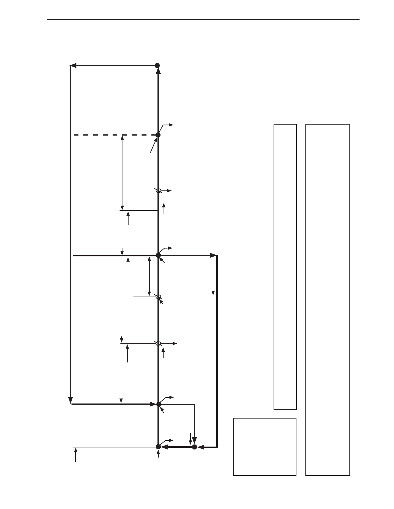
II. Sequence of Operation and Service Diagnosis
A. Sequence of Operation Flow Charts
1. Operation Flow Chart
FS check
1 to 3-min. harvest timer in
control (S4 dip switch 1 & 2)
Legend:
Comp–compressor
DV–drain valve
FM–fan motor
FMR–fan motor-remote
FS–oat switch
HGV–hot gas valve
LLV –liquid line valve
PM–pump motor
WV–inlet water valve
Components Energized when the Control Switch is in the "PUMP" Position
When the control switch is in the "PUMP" position, power is supplied to the pump motor. Water tank contents then ows over
the outside of the evaporator plate assembly. Note: Water tank contents does not ow in-between the evaporator plates.
Operation Flow Chart
1. 1-Minute
Fill Cycle
Cycle
Steps
2. Harvest Cycle
• WV time: 6 min. or the length of harvest minus 50 sec.
(S4 dip switch 7), whichever is shorter. Do not adjust S4
dip switch 7 out of the factory position.
• Max. harvest time: 20 min.
Thermistor
in control
3. Freeze Cycle
• Min. freeze time: 5 min.
• Max. freeze time: freeze timer setting
(S4 dip switch 9 & 10).
FS in control
4. Pump-Out Cycle
• Factory set for every 10th
cycle
(S4 dip switch 5)
• Pump motor de-energizes
for 2 sec., then energizes
for 10/20 sec.
(S4 dip switch 3 & 4)
WV energized
FS open
Comp energized
FMR energized
HGV energized
WV energized
Thermistor temperature reaches
48°F (9°C)(3.9 kΩ or less).
Harvest timer starts.
FS open
Comp energized
FM energized
FMR energized
PM energized
LLV energized
HGV de-energized
FS closed
Comp energized
DV energized
FMR energized
HGV energized
PM de-energizes for 2 sec.,
then energizes for 10/20 sec.
FM de-energized
LLV de-energized
FS check
Startup
If FS is open, Comp stops and cycle returns to 1-Min. ll.
5-min.
minimum
freeze timer in
control
FS closed
FS opens or freeze
timer terminates
50 sec.
PM energized
WV de-energized
Harvest Pump
Timer
Anti-Slush
Thermistor temperature
reaches 36°F (2.2°C)
(5.8 kΩ).
PM de-energized for
10 sec.
Components Energized when the Control Switch is in the "ON" or "PUMP" position and the
Mode Switch is in the "CLEAN" Position
• When the control switch is in the "ON" position and the mode switch is in the "CLEAN" position, power is supplied to the control board K9 connector.
The control board then initiates a clean/sanitize program. See the maintenance label on the top cover or the instruction manual for details.
• When the control switch is in the "PUMP" position and the mode switch is in the "CLEAN" position, only the pump motor energizes and circulates.
The Clean/Sanitize program cannot initiate in this scenario. This switch position allows for additional circulation of the water tank contents.
After 1-min. FS check and FS is open,
ll cycle continues until FS closes.
Once FS closes, harvest cycle begins.
14
2. Shutdown Flow Chart
Shutdown Flow Chart
1. Bin Full
Shutdown Delay:
• Fill Cycle–15 sec. after activation.
• Harvest Cycle–At the end of the harvest cycle, or up
to 15 sec. into the freeze cycle if
activated at the end of the harvest cycle.
• Freeze Cycle– 15 sec. after activation if activated at least
15 sec. before the 5-min. short cycle
protection timer terminates.
Otherwise, at the end of the next harvest
cycle.
Shutdown
and Restart
UBC Operation
UBC open (UBC sensor engaged)
Orange "BIN CLS" LED on
Orange "BIN CLS" LED continues. All
components de-energized.
2. Icemaker Off
All components
de-energized.
3. Ice Level Lowered
Icemaker starts at
"1. 1-Minute Fill Cycle."
UBC closed (UBC sensor disengaged)
Orange "BIN CLS" LED off
To 1. 1-Minute Fill Cycle
Legend:
UBC–ultrasonic bin control

15
B. Service Diagnosis
WARNING
• The appliance should be diagnosed and repaired only by qualied service
personnel to reduce the risk of death, electric shock, serious injury, or re.
• Risk of electric shock. Control switch in "OFF" position does not de-energize all
loads. Use extreme caution and exercise safe electrical practices.
• Moving parts (e.g., fan blade) can crush and cut. Keep hands clear.
• Before servicing the appliance, move the control switch to the "OFF" position and
turn off the power supply.
• CHOKING HAZARD: Ensure all components, fasteners, and thumbscrews are
securely in place after the appliance is serviced. Make sure that none have fallen
into the dispenser unit/ice storage bin.
• Make sure all food zones in the appliance and dispenser unit/ice storage bin are
clean after service.
The diagnostic procedure is a sequence check that allows you to diagnose the electrical
system and components. Before proceeding, check for correct installation, proper voltage
per nameplate, and adequate water supply. Check CB using the steps in "II.C. Control
Board Check." Check dip switch settings to assure that S4 dip switches (1 through 10)
and S5 dip switches (1 through 5) are in the factory default position. S4 dip switch 1,
2, 3, 4, and 5 are cleaning adjustments and the settings are exible. For factory default
settings, see "III.C.1. Default Dip Switch Settings."
Note: • When checking high voltage (115VAC), always choose a white (W) neutral wire to
establish a good neutral connection.
• When checking voltage from the CB K1 connector (10 pin connector), pull
CBK1connector out slightly to allow room for multimeter test leads contact.
1) Turn off the power supply, remove the front panel, then access the control box. Move the
control switch to the "OFF" position. Clear ice from UBC sensing area.
2) Check that the 115VAC 10A fuse is good.

16
a) Sequence and Component Diagnosis
3) Power On: Turn on the power supply, then move the control switch to the "ON" position
and the mode switch to the "ICE" position. A 5-sec. delay occurs. CB red "POWER" LED
turns on. If CB orange "BIN CLS" LED is on, see
"II.D.1. Ultrasonic Bin Control Check."
Note: • CB red "POWER" LED remains on unless the 10.5VAC power supply is
interrupted (K2 connector).
• Check CB using the steps in "II.C. Control Board Check" or check UBC using
steps in "II.D.1. Ultrasonic Bin Control Check."
a) Power On Diagnosis: If CB red "POWER" LED is off, conrm 10A fuse is good.
Check for 115VAC at control switch #2 (BK) to neutral (W) then at control switch
#1(P) to neutral (W). If 115VAC is present on #2 (BK) and not on #1(P), replace
control switch. If 115VAC is present on control switch #1 (P), check for 115VAC at
HPS (P) to neutral (W) then HPS (BK) to neutral (W). If115VAC is present at HPS
(P) and not at HPS (BK), HPS is open. See HPS Diagnosis below. If 115VAC is
present at HPS (BK), check for 10.5VAC at CB K2#1 red wire to CB K2 #2 red wire.
If 10.5VAC is not present, check CT continuity. If open, replace CT.
b) Power On Bin Control Diagnosis: If CB red "POWER" LED and CB "BIN CLS"
LED is on, clear UBC sensing area. If no object is in the area, replace UBC. If CB red
"POWER" LED is on and CB "BIN CLS" LED is off, see "II.D.1. Ultrasonic Bin Control
Check."
Note: CB delay time:
Sensing Ice: CB "BIN CLS" LED turns on within 5 to 15-sec.
Not Sensing Ice: CB "BIN CLS" LED turns off after 30-sec. delay.
c) HPS Diagnosis: If HPS is open: check that the condenser coil is not clogged or
restricted. Let the refrigeration circuit pressures equalize. If HPS does not reset
and pressures are equalized, replace HPS. If pressures are not equalized, reclaim
refrigerant and diagnose refrigeration circuit restriction. Check that there are no
restrictions in the refrigeration circuit.
Harvest Cycle: HGV, strainer, or check valve.
Freeze Cycle: FM, FMR, TXV, WRV, HM, LLV, strainer, check valve, drier, and
damaged line set or tting.
Conrm that the location meets installation requirements:
• The appliance is not intended for outdoor use. Normal operating ambient temperature
should be within 45°F to 100°F (7°C to 38°C).
• Allow 6" (15 cm) clearance at rear, sides, and top for proper air circulation and ease of
maintenance and/or service should they be required.
• The appliance should not be located in a corrosive environment.

17
4) 1-Min. Fill Cycle – WV LED is on. WV energizes. After 1 min., CB checks for a closed
FS. If FS is closed, the harvest cycle begins. If harvest cycle begins (Comp, HGV, FMR
energized), continue to step 5a. If FS is open, ll cycle continues until FS closes (low
water safety protection during initial start up and at the end of each harvest).
Diagnosis: Check that water enters the water tank. If not, check that the water supply
line shut-off valve is open and screens or external lters are clear. Check for 115VAC
at CB K1 #6 (O) to neutral (W). If 115VAC is not present, replace CB. If 115VAC is
present, and WV does not energize, check for 115VAC at WV. If 115VAC is present,
check coil continuity. If open, replace WV. If the water tank lls, but the appliance fails to
start harvest (Comp energized), check for open FS. See "II.E. Float Switch Check and
Cleaning." If FS is closed and CB fails to start the harvest cycle after 1 min., replace
CB.
5a) Initial Harvest Cycle – Comp, WV, and FM/HGV LEDs are on. WV continues. Comp,
FMR, and HGV energize. CB monitors the warming of the evaporator via the thermistor
located on the suction line. When the thermistor reaches 48°F (9°C), CB reads
3.9 kΩ from the thermistor and turns harvest termination over to the harvest timer
(S4 dip switch 1 & 2 and S5 dip switch 4). WV is energized during harvest for a
maximum of 6 min. or the length of harvest minus HPT setting (S4 dip switch 6),
whichever is shorter. See step 5b below.
a) Comp Diagnosis: Check that evaporator is warming. Ifnot, conrm that Comp
energizes. If not, check for 115VAC at CB K1 #9 (Y) to neutral (W). If 115VAC is not
present, check for 115VAC at CB K1 #10 (BK) to neutral (W). If 115VAC is present
at #10 (BK) and not at #9 (Y), replace CB. If 115VAC is present, check for 115VAC
at mode switch #2 (Y) to neutral and mode switch #1 (V) to neutral. If 115VAC is
present at #2 (Y) and not at #1 (V), conrm mode switch is in "ICE" position.
If in "ICE" position, check mode switch continuity. If open, replace mode switch.
If 115VAC is present at mode switch #1 (V), check for 115VAC at CR #0 (V) to CR
#1(W). If 115VAC is present, conrm contacts are closed. If not, replace CR. If CR
contacts are closed, check Comp external overload (Except KMD-705M_J(Z) See
Wiring Diagram), Comp start and run capacitors, Comp start relay, and Comp motor
winding.
b) HGV Diagnosis: If Comp is energized and evaporator is not warming, check that
HGV energizes and opens. Check for 115VAC at CB K1 #2 (P) to neutral (W).
If 115VAC is not present, check for 115VAC at CB K1 #1 (V). If 115VAC is not present,
check wiring for loose connection from CB 10 pin connector pin #1 (V) to mode
switch. If 115VAC is present on #1 (V) and not at #2 (P), replace CB. If 115VAC is
present at #2 (P), check for 115VAC at HGV coil and check HGV coil continuity.
Replace as needed.
c) LLV Diagnosis: Conrm that LLV is de-energized and closed (not bypassing).
If energized, replace CB. If de-energized and bypassing, replace LLV.
d) WRV Diagnosis: Conrm WRV is not leaking by. If WRV is leaking by, conrm HGV
is open and LLV is closed. Next, check for proper refrigerant pressures. If refrigerant
pressures are correct, adjust or replace WRV. See "IV.C. Water Regulating Valve
Adjustment (water-cooled models)."

18
5b) Harvest Pump Time (Harvest Assist) – Comp, PM, and FM/HGV LEDs are on.
When the thermistor reaches 48°F (9°C), CB reads 3.9 kΩ from the thermistor and
turns harvest termination over to the harvest timer (S4 dip switch 1 & 2 and S5 dip
switch 4). When WV de-energizes, WV LED turns off and PM LED turns on. PM
energizes. Comp, FMR, and HGV continue.
Diagnosis: Place a thermometer on the suction line next to the thermistor. Has it
warmed to 48°F (9°C) or warmer? Conrm thermistor status. See "II.F. Thermistor
Check." If the thermistor reading is in proper range, dip switch 7 is on, PM LED is on,
and PM has not energized before harvest terminates, check for 115VAC at CB K1 #4
(R). If 115VAC is not present, replace CB. If 115VAC is present, PM LED is on, and PM
has not energized before harvest terminates, check PM capacitor and motor winding
continuity. Replace PM capacitor and/or PM if needed. If WV continues, check for
115VAC at CB K1 #6 (O). If 115VAC is present, and WV LED is off, replace CB
5c) Initial Harvest Cycle Termination Diagnosis: When the thermistor reaches 48°F
(9°C), CB reads 3.9 kΩ from the thermistor and turns harvest termination over to
the harvest timer (S4 dip switch 1 & 2 and S5 dip switch 4). Check discharge line
temperature. For a thermistor check, see "II.F. Thermistor Check." If 1-min. ll cycle
starts after harvest timer terminates, check that FS is clean and operating properly, see
"II.E. Float Switch Check and Cleaning." If FS is closed, CB proceeds to the next cycle.
If not, replace CB.
Note: The minimum total time allowed by CB for a complete harvest cycle is based on
S5 dip switch 4. Maximum harvest time allowed is 20 min.
NOTICE! S4 dip switch 7 must remain on. Otherwise, PM will not energize during
the last seconds of harvest.
6) Freeze Cycle – Comp and PM LEDs are on. Comp, FMR, and PM continue. FM and
LLV energize. HGV de-energizes. Appliance is held in freeze by a 5-min. short cycle
protection timer. After 5-min. short cycle protection timer terminates and FS opens,
freeze cycle terminates.
Note: PM power supply continues from CB K1 #4 (R) in harvest and in freeze.
Anti-Slush: When anti-slush is enabled (S5 dip switch 5 "ON"), PM de-energizes when
thermistor reaches 36°F (2.2°C) (5.8 kΩ) for 10 sec. then, energizes for the remainder
of the freeze cycle.
a) Freeze Cycle Diagnosis: Conrm Comp, FMR, and PM continue. Conrm that FM
and LLV energize. Conrm WRV opens. Next, conrm HGV de-energizes. During the
rst 5 min. of freeze, conrm evaporator is cooling. If not, conrm WV de-energized
(not leaking by), HGV de-energized (not bypassing), LLV and FM energize, TXV
and HM operate correctly, WRV opens, Comp is efficient, and refrigerant charge is
correct. See "VIII.A. Specication and Performance Data Sheets."

19
b) Comp and FMR Diagnosis: If Comp and FMR de-energize once freeze begins,
check that appliance has not shut off on HPS (CB "POWER" LED off). If so, check
"3)b) HPS Diagnosis" above.
Comp Diagnosis: If CB "POWER" LED and Comp LED are on, check for 115VAC at
CB K1 #9 (Y) to neutral (W). If 115VAC is not present and Comp LED is on, replace
CB. If 115VAC is present, check for 115VAC at CR coil. If 115VAC is present, check
CR coil and contact continuity. Replace as needed. If CR is okay, check Comp start
relay and start and run capacitors. Next, check Comp motor winding continuity.
If Comp is energized but evaporator is not cooling, check for an inefficient Comp.
See "VIII.A. Specication and Performance Data Sheets."
FMR Diagnosis: If Comp LED is on and Comp is energized but FMR is not, check
for 115VAC at the FMR junction box. If 115VAC is not present, check icemaker wiring
connections. If 115VAC is present, check for voltage at condenser unit. If 115VAC
is not present, check eld wiring connections. If 115VAC is present, check FMR
capacitor, motor winding, and fan blade for binding.
c) PM Diagnosis: Conrm water is owing over evaporator from PM and not WV and
PM LED is on. If PM de-energizes once freeze begins, check for 115VAC at CB K1
#4 (R) to neutral (W). If 115VAC is not present and PM LED is on, replace CB.
If 115VAC is present and PM is de-energized, check PM capacitor and motor winding
continuity. Replace PM capacitor and/or PM if needed.
d) FM and LLV Diagnosis: If FM or LLV does not energize, check for 115VAC at CB
K1#3 (BK) to neutral (W). If 115VAC is not present and FM/HGV LED is off, check
for 115VAC at CB K1 #1 (V). If Comp LED is on and 115VAC is present at #1 (V) and
not at #3 (BK), replace CB. If 115VAC is present at #3 (BK) and FM/HGV LED is on:
For FM, check capacitor, motor winding, and blade for binding.
For LLV, check coil voltage and continuity.
Note: FM is OFF when FM/HGV LED is ON.
e) WV and HGV Diagnosis:
WV Diagnosis: If WV LED is on and WV is energized, check for 115VAC at CB
K1 #6 (O) to neutral (W). If 115VAC is present after PM energizes in harvest cycle,
replace CB. If 115VAC is not present, replace WV (bypassing).
HGV Diagnosis: If HGV did not de-energize at the end of harvest, check for 115VAC
at CB K1 #2 (P) to neutral (W). If 115VAC is present at CB K1 #2 (P) and FM/HGV
LED is off, replace CB. If 115VAC is not present at CB K1 #2 (P), replace HGV
(bypassing).
f) Refrigerant Pressures, HM, and TXV Diagnosis: If evaporator is still not cooling,
check refrigerant pressures. See "VIII.A. Specication and Performance Data
Sheets." Next, check HM operation. If refrigeration pressures are above HM setpoint
and HMis bypassing, replace HM. Check TXV for proper operation. Remove TXV
bulb and hold it in your hand, refrigerant low-side pressure should rise, place
TXV bulb in ice water, refrigerant low-side pressure should drop. A 10 to 15 pound
pressure swing between warm and cold conditions indicate a good TXV. If a 10 to 15
pound swing is not present, replace TXV.
20
g) WRV Diagnosis: WRV is factory set and generally no adjustment is required.
IfWRV fails to open in freeze, check for proper refrigerant pressures. See "VIII.A.
Specication and Performance Data Sheets." If refrigerant pressures are correct and
WRV does not open, adjust or replace as needed. See "IV.C. Water Regulating Valve
Adjustment (water-cooled model)."
h) Freeze Termination Diagnosis: After 5 min. in freeze, disconnect CB K5 FS
connector. 15 sec. later appliance switches out of the freeze cycle (15 second delay
after FS opens before terminating the freeze cycle). If appliance remains in freeze
longer than 15 sec. after FS removed, replace CB. If appliance switches with FS
removed but would previously not switch out of freeze with FS connected (long
freeze - 3 beep alarm), see "II.E. Float Switch Check and Cleaning."
Note: Normal freeze cycle will last 20 to 40 min. depending on model and conditions.
Cycle times and pressures should follow performance data provided in this
manual. See "VIII.A. Specication and Performance Data Sheets."
i) Short Freeze Cycle Diagnosis: Conrm water tank lls and overows during 1-min.
ll and harvest cycles. If not, check water supply lters, shut-off valve, WV screen.
Ifwater tank empties before 5-min. timer terminates and freeze cycle is short, check
that DV is not leaking by (water owing down the drain). If DV is leaking by, remove
and clean DV, replace if necessary. If water tank is full, see "II.E. Float Switch Check
and Cleaning." for erratic operating FS.
7) Pump-Out Cycle – Comp, PM, FM/HGV and DV LEDs are on (10/20 second
pump-out). Timing of the rst pump-out is determined by S4 dip switch 5. See the table
below.
Control Board Settings
S4 Dip Switch Setting
Pump-Out
Frequency
1st Pump-Out
No. 5
OFF Every 10 cycles After 11th freeze cycle
ON Every cycle After 2nd freeze cycle
Comp and FMR continue, HGV energizes.
Note: If S4dip switch 3 & 4 are set to 3 off and 4 on, WV LED turns on and WV
energizes. NOTICE!S5dip switch 1 must not be adjusted. This is the pump-out
circulation selection and allows DV to energize in pump-out.
FM and LLV de-energize. PM stops for 2 sec., then PM (LED on) and DV (LED on)
energize for 10/20 sec. depending on pump-out timer (S4 dip switch 3 & 4) setting.
When the pump-out timer terminates, pump-out is complete. The pump-out frequency
control (S4 dip switch 5) is factory set, and generally no adjustment is required.
However, the pump-out frequency control can be set to have a pump-out occur every
10 cycles or every cycle. For details, see "III.C.4. Pump-Out Frequency Control (S4 dip
switch 5)."

21
Pump-Out Diagnosis: In the freeze cycle before pump-out (see table above), after
5min. of freeze disconnect CB black K5 connector (FS connector). Check that PM
stops and re-starts. Next, check that PM and DV energized (water owing down the
drain through DV). If PM does not stop and re-start, check that CB Comp, PM, and DV
LEDs are on. If not, replace CB. If Comp, PM, and DV LEDs are on and PM does not
energize, check for 115VAC at CB K1 #4 (R) to neutral (W). If 115VAC is not present,
replace CB. If not, check PM motor windings and impeller for binding. If energized,
make sure DV energized. If not, check for 115VAC at CB K1 #5 (W/BU). If 115VAC is
not present and DV LED is on, replace CB. If 115VAC is present, check DV solenoid
continuity. Replace as needed. If DV is energized and open, check that the drain line is
not clogged.
Conrm FM and LLV de-energize. If FM or LLV are energized with Comp, PM, and DV
LEDs on, replace CB.
8) Normal Harvest Cycle – Same as the initial harvest cycle. Return to step 5a) above.
Note: Appliance continues to cycle until UBC is satised or power is switched off.
The appliance always restarts at the 1-min. ll cycle.
b) Shutdown Diagnosis
1) See "II.D.1. Ultrasonic Bin Control Check."
Legend: CB–control board; Comp–compressor; CR–compressor relay; CT–control
transformer; CV–cleaning valve; DV–drain valve; FM–fan motor; FMR–fan motor
remote; FS–oat switch; HGV–hot gas valve; HM–headmaster (C.P.R.);
HPS–high-pressure switch; HPT–harvest pump time; LLVs–liquid line valve;
PM–pump motor; TXV–thermostatic expansion valve; UBC–ultrasonic bin control;
WRV–water regulating valve; WV–inlet water valve
22
C. Control Board Check
Before replacing CB that does not show a visible defect and that you suspect is bad,
always conduct the following check procedure. This procedure will help you verify your
diagnosis.
Alarm Reset: If CB is in alarm (beeping), press the "ALARM RESET" button on CB while
CB is beeping. WARNING!Risk of electric shock. Care should be taken
not to touch live terminals. Once reset, the icemaker starts at the 1-min.
ll cycle. For audible alarm information, see "III.B. LED Lights and Audible
Alarm Safeties."
1) Check the dip switch settings to assure that S4 dip switch 3, 4, 7, 8, 9, 10 and S5 dip
switch 1 through 5 are in the factory default position. S4 dip switch 1, 2, 5,and 6 are
cleaning adjustments and the settings are exible. For factory default settings, see
"III.C.1. Default Dip Switch Settings."
2) Move the control switch to the "ON" position and the mode switch to the "ICE" position.
If the red CB "POWER" LED is on, control voltage is good, continue to step 3).
If CB "POWER" LED is off, check CT secondary circuit. CT output is 10.5VAC at
115VAC primary input. If the secondary circuit has proper voltage and the red LED is
off, replace CB.
If the secondary circuit does not have proper voltage, check CT primary circuit. Check
for 115VAC at CB K1 connector pin #10 (BK) to neutral (W) for 115VAC. Always choose
a white (W) neutral wire to establish a good neutral connection when checking voltages.
For additional checks, see "II.I.1. No Ice Production."
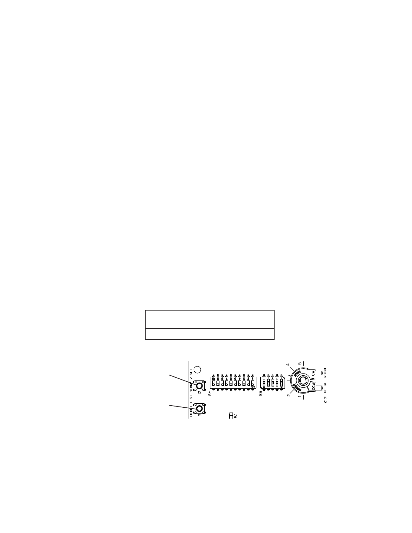
3) The "OUTPUT TEST" button provides a relay sequence test. Make sure the control
switch is in the "ON" position and the mode switch is in the "ICE" position, then press
the "OUTPUT TEST" button. For the correct lighting sequence, see the table below.
Note that the order of the LEDs from the outer edge of the control board is Comp, CV,
WV, DV, PM, FM/HGV. Components cycle during the test. See Fig. 1.
Control Board (2A9678-01)
• "ALARM RESET" Button
(white)
• "OUTPUT TEST" Button
(black or white)
Fig. 1
Following the output test cycle, the icemaker begins normal icemaking operation at the
1-min. ll cycle. If the LEDs do not light as described above, replace CB.
IMPORTANT! Do not press the "OUTPUT TEST" button while CB is in alarm.
See Fig. 1. Pressing the "OUTPUT TEST" button while CB is in alarm initiates an output
test and locks out the "ALARM RESET" button. To reset the "ALARM RESET" button,
turn the power power off and back on.
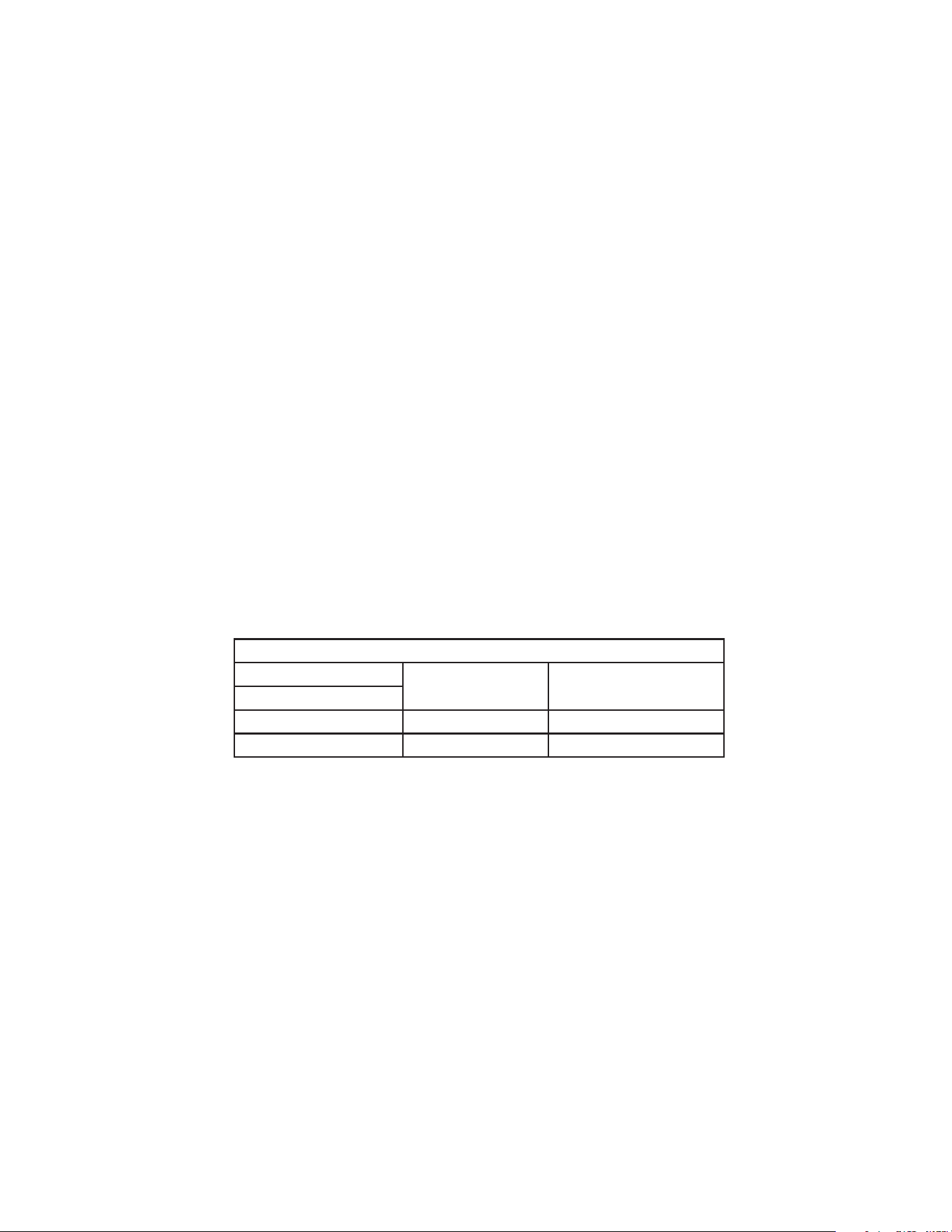
Correct LED
Lighting Sequence
Comp, CV, WV, DV, PM, FM/HGV
23
4) To verify voltage output from CB to the components, slide the CB K1 connector out far
enough to allow multimeter lead contact. With the icemaker in the cycle to be tested,
check output voltage from the corresponding pin on CB K1 connector to a neutral (W)
wire. If output voltage is not found and the appropriate LED is on, replace CB.
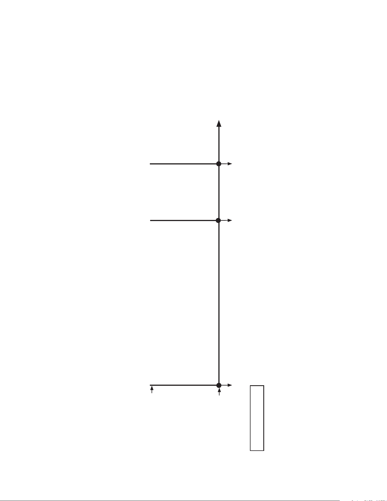
5) 5VDC Output Checks: When checking 5VDC control voltage, always place the red
positive test lead from the multimeter to the CB white K11 pin closest to the CB white
K13 connector. See Fig. 2a. Then place the black negative test lead from the multimeter
to the corresponding pin to complete the 5VDC check.
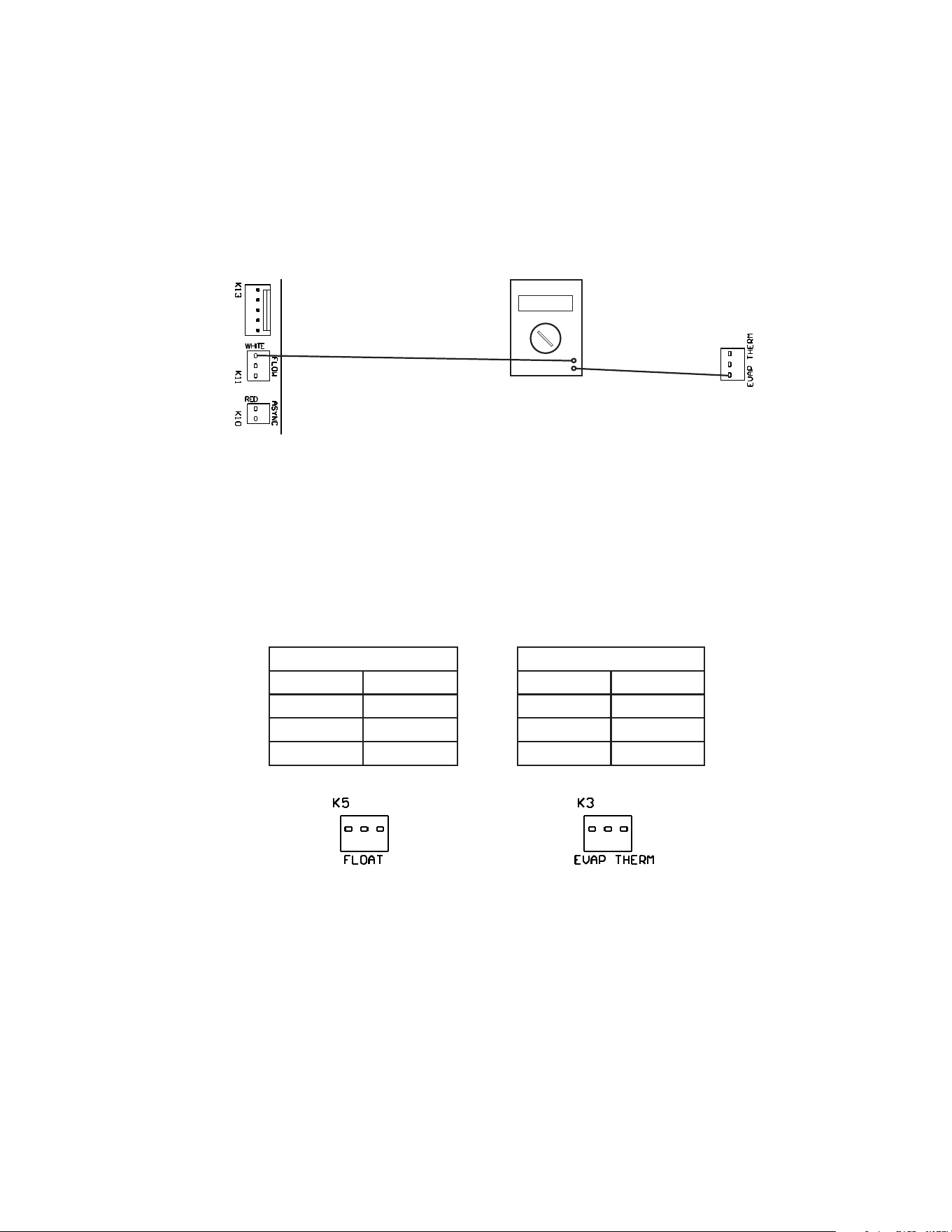
6) Check CB control connectors K3 (Evaporator Thermistor) and K5 (Float Switch) for
correct VDC per table below. See Fig. 2b.
Legend: CB–control board; CT–control transformer
CB
K+ Control Board (2A9678-01)
K3 Thermistor
Pin # VDC
#1 to #2 5VDC
#1 to #3 5VDC
#2 to #3 0VDC
K5 Float Switch
Pin # VDC
#1 to #2 1.2VDC
#1 to #3 2VDC
#2 to #3 1.2VDC
Fig. 2b
Fig. 2a
Black Negative
Test Lead
Multimeter
5VDC
Red positive test lead to K11
pin closest to K13 connector
Red Positive
Test Lead
K3
24
D. Bin Control Check and Adjustment
WARNING
• All parts are factory-adjusted. Improper adjustments may adversely affect safety,
performance, component life, and warranty coverage.
• In Hoshizaki DB and DM dispenser applications, the bin control controller setting
must be adjusted to 2. For Coca-Cola Freestyle® Dispenser and other dispenser
applications, the bin control controller setting must be adjusted to 3. Increasing
the ice level on any dispenser application could lead to icemaker movement,
water leakage, or ice overow.
• Be sure control switch is in "OFF" position and components (fan blade) have
stopped moving before attempting to remove or replace the bin control sensor.
NOTICE
• Do not block the bin control lens with top kits or the icemaker will not operate
properly.
• Failure to properly adjust the bin control setting could result in water leakage, ice
backup, and icemaker damage.
1. Ultrasonic Bin Control Check
Before replacing UBC sensor and CB that does not show a visible defect and you
suspect is bad, always conduct the following check procedure. This procedure will help
you verify your diagnosis. Note: It is strongly advised to keep a known "good" UBC
sensor on your truck, for troubleshooting assistance.
The ultrasonic bin control is factory set for use on Hoshizaki America standard ice
storage bins.
If mounted on a dispenser application or if a change to the ice level in an ice storage bin
application is desired, see "II.D.2. Ultrasonic Bin Control Adjustment."
1) Remove the front panel. Move the control switch to the "OFF" position, then remove the
top panel, right side panel, and control box cover. See Fig. 3.
2) Clear ice away from UBC area and conrm that the UBC lens is clean.
3) Place the mode switch in the "ICE" position, then move the control switch to the "ON"
position. See Fig. 3.
Ultrasonic
Bin Control Lens
Icemaker
Control Switch
Mode Switch
Control Box Cover
Fig. 3
25
4) Bin Empty Diagnosis: As water begins to ll the water tank (1-min. ll), place an object
5" to 7" (127 to 178mm) away from the UBC lens. See Fig. 3. CB 5-sec. delay timer
starts. "BIN CLS" LED turns on. CB 5-sec. delay timer terminates, CB 15-sec. delay
timer starts. CB 15-sec. delay timer terminates and the icemaker shuts down. Remove
the object from the UBC lens. CB 30-sec. delay timer starts. CB 30-sec. delay timer
terminates, CB "BIN CLS" LED turns off, and the icemaker restarts. Note: In some
cases, removing the UBC sensor and rotating the UBC lens up and down, provides
better access when troubleshooting.
Cycle at Bin
Control Activation Control Board Shutdown
Fill Cycle 15 sec. after activation.
Harvest Cycle If engaged 15 sec. or longer, at the end of harvest cycle.
Freeze Cycle 15 sec. after activation if activated at least 15 sec. before the 5-min. short cycle
protection timer terminates. Otherwise, at the end of the next harvest cycle.
Ice Level in Bin "BIN CLS" LED
Empty OFF
Full ON
5) Bin Full Diagnosis: Place an object 5" to 7" (127 to 178mm) away from the UBC lens.
See Fig. 3. If shut down cycle does not start, conrm CB "BIN CLS" LED turns on.
If not, conrm object placement. If object placement is correct, replace UBC sensor
and CB. If CB orange "BIN CLS" LED turns on and shut down cycle does not start, see
"II.B.1.4) 1-min. Fill Cycle."
Note: In some cases, removing the UBC sensor and rotating UBC lens up and down,
provides better access when troubleshooting.
6) Once the icemaker restarts, move the control switch to the "OFF" position, then turn off
the power supply.
7) Replace the control box cover, right side panel, and top panel in their correct position.
8) Move the control switch to the "ON" position. Replace the front panel in its correct
position, then turn on the power supply to start the automatic icemaking process.
Legend: UBC–ultrasonic bin control; CB–control board
26
2. Ultrasonic Bin Control Adjustment
WARNING
• All parts are factory-adjusted. Improper adjustments may adversely affect safety,
performance, component life, and warranty coverage.
• In Hoshizaki DB and DM dispenser applications, the bin control controller setting
must be adjusted to 2. For Coca-Cola Freestyle® Dispenser and non-Hoshizaki
dispenser applications, the bin control controller setting must be adjusted to 3.
Increasing the ice level on any dispenser application could lead to icemaker
movement, water leakage, or ice overow.
NOTICE
• Do not block the bin control lens with top kits or the icemaker will not operate
properly.
• Failure to properly adjust the bin control setting could result in water leakage, ice
backup, and icemaker damage.
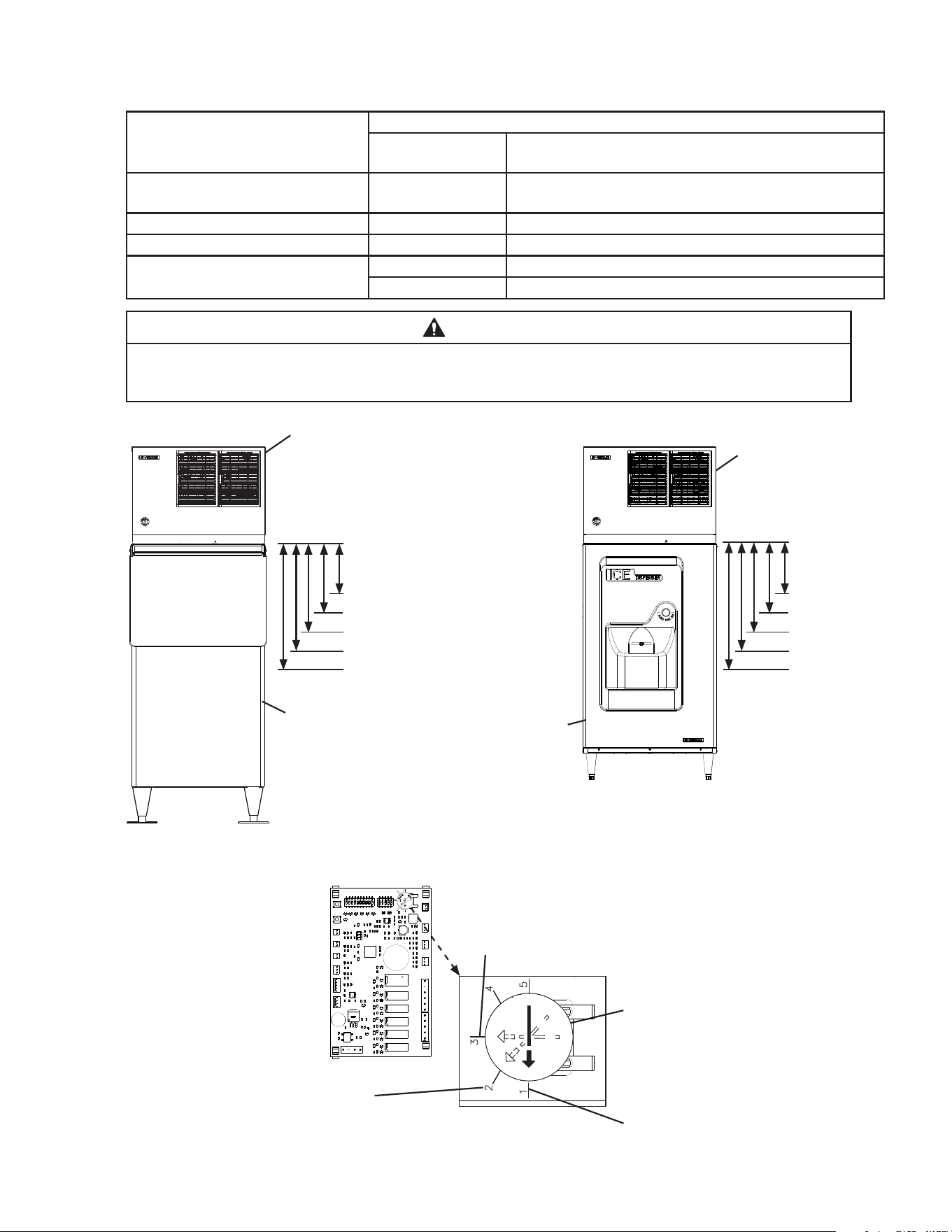
The ultrasonic bin control is factory set to 1 for use on Hoshizaki America standard ice
storage bins. See the table below for adjustments to ice level.
WARNING! Do not adjust outside of these settings.
1) If not already removed, remove the front, top, and right side panels. Next, remove the
control box cover.
2) Conrm ultrasonic bin control setting for proper application. See the table below for
settings. See Fig. 4. for ice level reference.
Note: Bin Control setting is for distance only. For time to shutdown, see "II.A.2.
Shutdown Flow Chart".
Application Bin Control Setting Reference
Standard Ice Storage Bins (Factory Default) 1 See Fig. 4
Hoshizaki DB and DM Dispensers 2
Coca-Cola Freestyle
®
Dispensers 3
Non-Hoshizaki Dispensers Measurement Required See Fig. 5
27
For Standard Ice Storage Bins, Hoshizaki DB and DM Dispenser Units, and Coca-Cola
Freestyle
®
Dispenser Units
Application Bin Control Ice Level Settings
Bin Control Setting
Shutdown Distance From Bin Control Lens
(Restart is 4 in. (102 mm) below shutdown distance)
Standard Ice Storage Bins 1
(Factory Default)
304 mm (12")
Do not adjust dispensers to this setting.
Hoshizaki DB and DM Dispensers 2 335 mm (13")
Coca-Cola Freestyle
®
Dispensers 3 416 mm (16 3/8")
Optional Setting 4 522 mm (20.5")
5 610 mm (24")
WARNING
Conrm that the nal ice level location does not allow for icemaker movement,
water leakage, or ice overow.
Fig. 4
Control Board
Recommended Setting for
Hoshizaki DB and DM Dispensers
Recommended Setting for Coca-Cola Freestyle®
Dispensers
Icemaker
Hoshizaki DB-200H
Dispenser Unit
Model Shown:
KMD-505MAJ with DB-200H
Model Shown:
KMD-505MAJ with B-500SF
Icemaker
Standard Ice
Storage Bin
Turn dial to adjust to proper setting
Factory Default for Standard
Ice Storage Bins
WARNING! Do not use this
setting with dispensers.
Ultrasonic
Bin Control
Lens
Setting #1
Setting #3
Setting #4
Setting #5
Setting #2
Ultrasonic
Bin Control
Lens
Setting #1
Setting #3
Setting #4
Setting #5
Setting #2
28
For Non-Hoshizaki Dispenser Units
Bin Control Ice Level Settings
Bin Control Setting
Shutdown Distance From Bin Control Lens
(Restart is 4 in. (102 mm) below shutdown distance)
1
(Factory Default)
304 mm (12")
Do not adjust dispensers to this setting.
2 335 mm (13")
3 416 mm (16 3/8")
4 522 mm (20.5")
5 610 mm (24")
WARNING
Conrm that the nal ice level location does not allow for icemaker movement,
water leakage, or ice overow.
NOTICE
The ice level must be lower than the top of the dispenser unit. Also, be sure the top
kit or top kit riser (if applicable) are clear from the bin control lens sensing area.
Fig. 5
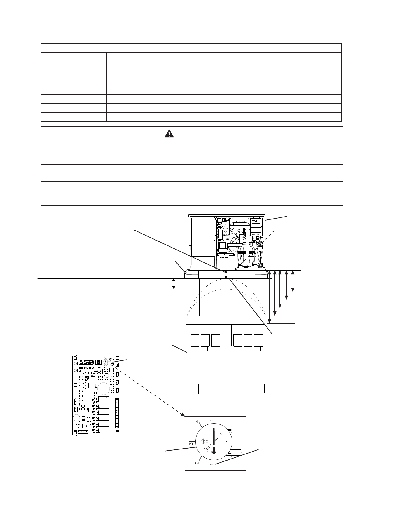
Full Bin Measured Distance
(Shutdown Distance) Measure from
the bottom of the compressor base
(bin control lens) to the preferred
full bin level of ice; refer to the
dispenser instruction manual.
Icemaker Restart Level
(4" (102 mm) below preferred
full bin level of ice)
Set Bin Control Setting at or Below Maximum Full
Bin Level of Ice (Shutdown Position) Shown Here
Top Kit
Icemaker
Non-Hoshizaki
Dispenser Unit
Bin Control Setting
Ultrasonic
Bin Control Lens
Control Board
Factory Default for Standard
Ice Storage Bins
WARNING! Do not use this
setting with dispensers.
Turn dial to adjust to setting
that matches Full Bin Measured
Distance (Shutdown Distance)
Ultrasonic
Bin Control
Lens
Setting #1
Setting #3
Setting #4
Setting #5
Setting #2
Maximum Full Bin Level of
Ice (Shutdown Position).
WARNING! Do not adjust
bin control setting above
this level.
Model Shown: KMD-505MAJ
29
E. Float Switch Check and Cleaning
The FS is used to determine whether there is sufficient water in the water tank after the
1-min. ll cycle and after each harvest cycle. The FS is also used to determine that the
appropriate volume of water has been converted into ice before switching out of the
freeze cycle. Noadjustment is required.
1. Float Switch Check
1) Turn off the power supply.
2) Remove the front panel, then move the
control switch to the "OFF" position.
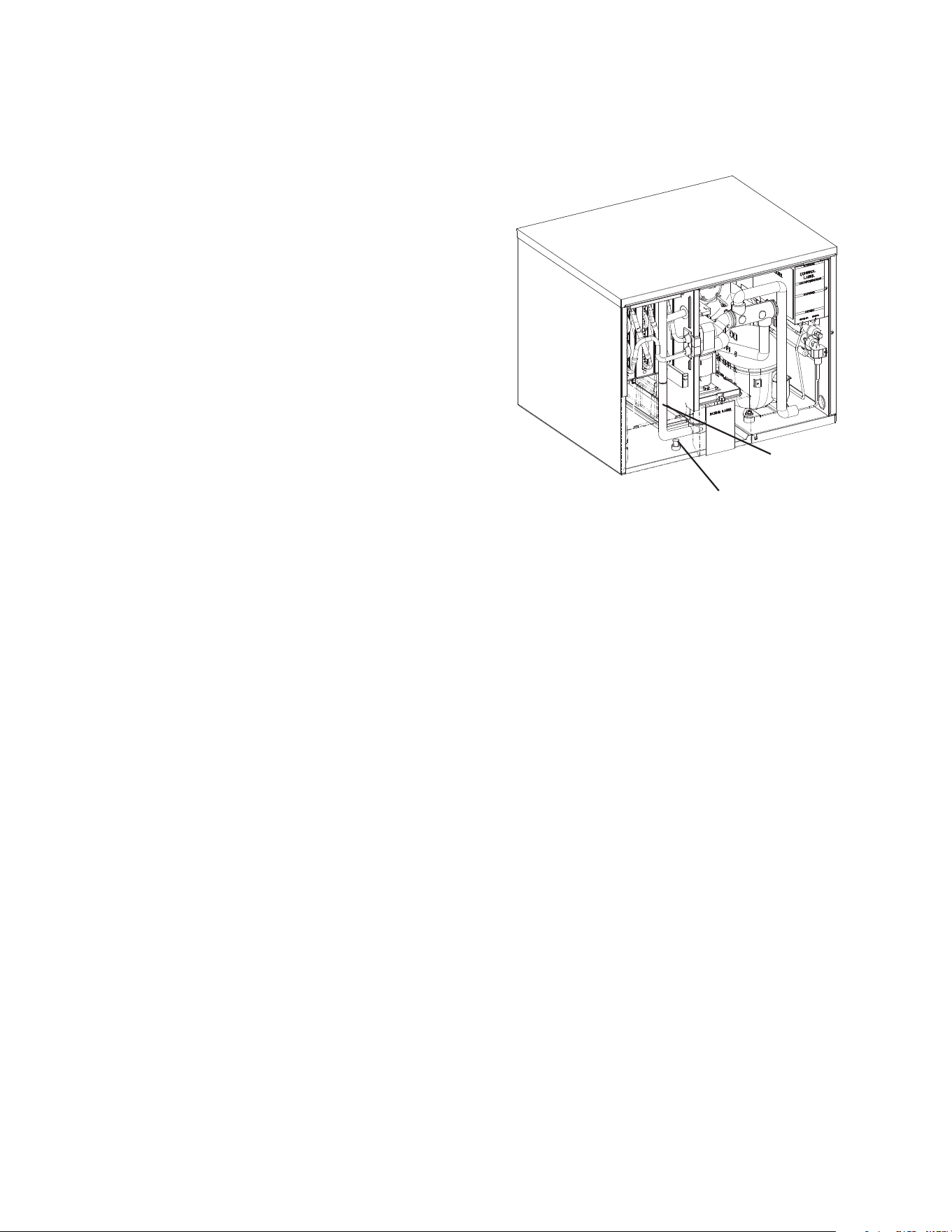
3) Drain the water tank. Remove the front
insulation panel, then remove the drain
plug located in the bottom of the water
tank. SeeFig. 6. After the water tank has
drained, replace the drain plug in its correct
position.
4) Remove the control box cover.
5) Disconnect the FS connector from CB K5connector.
6) Check for continuity across FS leads. With the water tank empty, FS should be open.
If open, continue to step 7. If closed, follow the steps in "II.E.2. Float Switch Cleaning."
After cleaning FS, check it again. Replace if necessary.
7) Reconnect the FS connector to CB K5 connector, then replace the control box cover in
its correct position.
8) Move the control switch to the "ICE" position. Replace the front insulation and front
panel in their correct position, then turn on the power supply. After 1 min., the 1-min. ll
cycle should end and the initial harvest cycle should begin. If the initial harvest cycle
begins, FS is good and the check is complete. If the initial harvest cycle does not begin,
continue to step 9.
9) Turn off the power supply.
10) Remove the front panel. Move the control switch to the "OFF" position.
11) Remove the control box cover.
12) Disconnect FS connector from CB K5 connector.
13) Check for continuity across FS leads. With the water tank full, FS should be closed.
IfFS is closed and the icemaker will not switch from the 1-min. ll cycle to the initial
harvest cycle, replace CB. If FS is open, conrm that the water tank is full. If the water
tank is not full, check the water supply, water lters, and inlet water valve. If the water
tank is full, follow the steps in "II.E.2. Float Switch Cleaning." After cleaning FS, check it
again. Replace if necessary.
14) Replace the control box cover in its correct position.
15) Move the control switch to the "ICE" position, then replace the front panel in its correct
position. Turn on the power supply to start the automatic icemaking process.
Legend: CB–control board; FS–oat switch
Drain Plug
Fig. 6
Discharge Hose
30
2. Float Switch Cleaning
Depending on local water conditions, scale may build up on the FS. Scale on the switch
can cause the oat to stick. In this case, the FS should be cleaned.
1) Turn off the power supply.
2) Remove the front panel, then move the control switch to the "OFF" position.
3) Remove the front insulation panel, remove the drain plug in the bottom of the water
tank. Disconnect the discharge hose from the bottom of the pump motor. See Fig. 6.
After the water tank has drained, replace the drain plug.
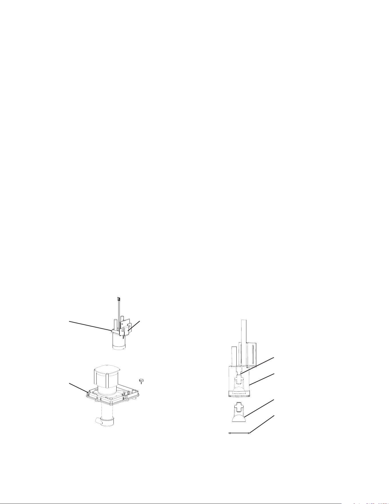
4) Remove the pump motor assembly, then push in the tab on the oat switch bracket to
release the oat switch assembly from the pump motor assembly. See Fig. 7.
5) Remove the spring retainer clip from the oat switch rod, then remove the oat.
Be careful not to bend the spring retainer clip excessively when removing it. See Fig. 8.
6) Wipe down the oat switch bracket assembly, stem, and oat with a mixture of 1 part
Hoshizaki "Scale Away" and 25 parts warm water. Rinse the parts thoroughly with clean
water.
7) Reassemble the oat switch assembly and replace it in its correct position.
8) Replace the pump motor assembly in its correct position.
9) Reconnect the discharge hose in its correct position.
10) Move the control switch to the "ICE" position.
11) Replace the front panel insulation and front panel in their correct positions.
12) Turn on the power supply to start the automatic icemaking process.
13) Conrm that there are no leaks at the drain plug.
Legend: FS–oat switch
Fig. 7
Float Switch
Assembly
Shaft
Fig. 8
Pump Motor
Assembly
Float Switch Housing
Float
Retainer Rod
Float Switch
Bracket Tab

31
F. Thermistor Check
To check thermistor resistance, follow the steps below.
1) Turn off the power supply.
2) Remove the front panel. Move the control switch to the "OFF" position, then remove the
top and right side panels.
3) Remove the thermistor from the refrigerant tubing.
4) Immerse the thermistor sensor portion in a glass containing ice and water for 2 or
3 min.
5) Disconnect the thermistor connector from CB K3 connector and check the resistance
between thermistor leads. Normal range is 4.7 to 6.2 kΩ. If outside the normal range,
replace the thermistor with Service Kit SP-5672. See "IV.B. Component Service
Information." If within the normal range, continue to the next step.
6) Replace the thermistor in its correct position. See "IV.B. Component Service
Information."
7) Reconnect the thermistor connector to CB K3 connector.
8) Replace the right side and top panels in their correct positions.
9) Move the control switch to the "ICE" position.
10) Replace the front panel in its correct position.
11) Turn on the power supply.
12) Once the harvest cycle starts (Comp energizes), begin timing the harvest cycle.
13) The harvest timer and harvest cycle should terminate within 2 to 5 min. If the harvest
cycle does not terminate within 2 to 5 min., replace CB.
Legend: CB–control board; Comp–compressor
G. Control Switch
The control switch has three positions: "ON" for power on, "PUMP" to energize the
pump motor and circulate the water in the water tank, and "OFF" to turn power off.
WARNING! Moving control switch to "OFF" position does not de-energize all
components.
H. Mode Switch
The mode switch has two positions: "ICE" for icemaking cycle, "CLEAN" for initiating the
cleaning and sanitizing program.
32
I. Diagnostic Tables
1. No Ice Production
No Ice Production - Possible Cause
1. Power Supply a) Off, blown fuse, or tripped breaker.
b) Not within specications.
2. Fuse (Control Box) a) Blown.
3. Control Switch a) In "OFF" or "PUMP" position.
b) Defective.
4. High-Pressure Switch a) Dirty condenser.
b) Fan motor not operating.
c) Refrigerant overcharged.
d) Bad contacts.
e) Refrigerant lines or components plugged.
5. Control Transformer
(115VAC/10.5VAC)
a) Coil winding open or shorted.
6. Control Board
See "II.C. Control Board Check"
a) In alarm.
b) CB orange "BIN CLS" LED on (bin full)(open).
c) Defective.
7. Bin Control
See "II.D.1. Ultrasonic Bin
Control Check"
a) Tripped with bin lled with ice.
b) Ultrasonic Bin Control lens dirty.
c) Defective.
8. Mode Switch a) In "CLEAN" position.
b) Defective.
9. Water Supply a) Water supply off or improper water pressure.
b) External water lters clogged.
10. Inlet Water Valve a) Screen or orice clogged.
b) Coil winding open.
c) Water valve open in freeze cycle.
11. Float Switch
See "II.E. Float Switch Check
and Cleaning"
a) Float does not move freely.
b) Defective.
12. Compressor a) Compressor relay/magnetic contactor contacts bad or coil winding
open.
b) Start capacitor or run capacitor defective (single phase).
c) Internal protector open.
d) Start relay contacts bad or coil winding open (single phase).
e) Compressor defective.
13. Hot Gas Valve a) Closed in harvest cycle.
b) Open in freeze cycle.
14. Thermistor
See "II.F. Thermistor Check"
a) Loose, disconnected, or defective.
33
No Ice Production - Possible Cause
15. Pump Motor a) Motor winding open.
b) Bearing worn out or locked rotor.
c) Defective capacitor.
d) Mechanical seal worn out.
16. Thermostatic Expansion Valve a) Bulb loose.
b) Operating erratically.
1 7. Liquid Line Valve a) Closed in freeze cycle.
b) Open in harvest cycle.
18. Fan Motor a) Motor winding open.
b) Bearing worn out or locked rotor.
c) Defective capacitor.
19. Water System a) Water leaks causing short freeze time.
2. Freeze-Up
Defrost and clean the icemaker prior to diagnosing freeze-up. Fill out a freeze-up checklist.
See "II.J. Freeze Up Check List," the Hoshizaki America Technician's Pocket Guide, or
contact your local distributor for a copy of the freeze-up checklist.
Freeze-Up - Possible Cause
Harvest Cycle
1. Evaporator a) Scaled up.
b) Damaged.
2. Cube Guides a) Out of position.
b) Damaged.
3. Spray Tubes and/or Spray
Guides
a) Dirty.
b) Out of position.
4. Water Supply a) Low water pressure.
b) External water lters clogged.
c) Insufficient water line size.
Minimum 1/4" Nominal ID (6 mm Nominal OD in the EU) copper
water tubing or equivalent.
5. Inlet Water Valve a) Screen or orice clogged.
b) Defective.
6. Float Switch
See "II.E. Float Switch Check
and Cleaning"
a) Dirty, sticking.
b) Defective.
7. Refrigerant Charge a) Low.
8. Control Board
See "III.C. Settings and
Adjustments" and "II.C. Control
Board Check"
a) Harvest timer (S4 dip switch 1 & 2) set too short.
b) Harvest pump timer (S4 dip switch 7) not in factory default position.
c) Defective.
9. Ultrasonic Bin Control
See "II.D.1. Ultrasonic Bin
Control Check", "II.D.2.
Ultrasonic Bin Control
Adjustment."
a) Defective.
34
Freeze-Up - Possible Cause
10. Thermistor
See "II.F. Thermistor Check"
a) Loose, disconnected, or defective.
11. Thermostatic Expansion Valve a) Defective.
12. Hot Gas Valve a) Defective.
13. Liquid Line Valve a) Defective.
Freeze Cycle
1. Evaporator a) Scaled up.
b) Damaged.
2. Spray Tubes and/or Spray
Guides
a) Dirty.
b) Out of position.
3. Refrigerant Charge a) Low.
4. Control Board
See "II.C. Control Board Check"
a) Freeze timer (S4 dip switch 9 & 10) set incorrectly.
b) Defective.
5. Inlet Water Valve a) Leaking by.
6. Float Switch
See "II.E. Float Switch Check
and Cleaning"
a) Float does not move freely.
b) Defective.
7. Pump Motor a) RPM too slow.
b) Impeller damaged.
8. Thermostatic Expansion Valve a) Bulb loose or defective.
9. Liquid Line Valve a) Restricted.
10. Headmaster (C.P.R.)
(remote models)
a) Not bypassing.
3. Low Ice Production
Low Ice Production - Possible Cause
Long Harvest Cycle
1. Evaporator a) Scaled up.
2. Spray Tubes and/or Spray
Guides
a) Dirty.
b) Out of position.
3. Refrigerant Charge a) Low.
4. Water Supply a) Low water pressure.
b) External water lters clogged.
c) Insufficient water line size.
Minimum 1/4" Nominal ID (6 mm Nominal OD in the EU) water
tubing or equivalent.
d) Too cold.
5. Control Board
See "II.C. Control Board Check"
a) Thermistor connection loose (K3).
b) Defective.
6. Thermistor
See "II.F. Thermistor Check"
a) Loose, disconnected, or defective.
7. Hot Gas Valve a) Erratic or closed.
8. Inlet Water Valve a) Screen or orice clogged.
9. Compressor a) Inefficient or off.
10. Liquid Line Valve a) Erratic or open.
11. Thermostatic Expansion Valve a) Defective.
35
Low Ice Production - Possible Cause
Long Freeze Cycle
1. Evaporator a) Scaled up, dirty.
2. Float Switch
See "II.E. Float Switch Check
and Cleaning"
a) Scaled up, dirty.
b) Float sticking.
c) Defective switch.
3. Inlet Water Valve a) Leaking by.
4. Hot Gas Valve a) Erratic or open.
5. Condenser a) Clogged.
6. Control Board
See "II.C. Control Board Check"
a) Float switch connection loose (K5).
b) Defective.
7. Refrigerant Charge a) Low.
8. Thermostatic Expansion Valve a) Bulb loose.
b) Defective.
9. Compressor a) Inefficient or off.
10. Pump Motor a) RPM too slow.
11. Liquid Line Valve a) Erratic or restricted.
12. Headmaster (C.P.R.)
(remote models)
a) Not bypassing.

36
J. Freeze-Up Check List
1
Freeze-Up Check List
Please Complete When Diagnosing a Freeze-Up, Refrigerant Leak, or Low Charge
Technical Support Fax #: 770-487-3360
Make Copies And Use As Needed
Model #___________________________ Serial # ______________________Install Date__________Freeze-Up Date___________
List model and manufacture of bin or dispenser__________________________.
Date appliance was last cleaned:__________.
Freeze-Up Defrost
YES NO
[ ] [ ] 1) After defrosting, was the appliance leak
checked?
[ ] [ ] 2) Were any leaks found?
If so where?_____________________.
[ ] [ ] 3) Was any refrigerant added to the unit?
If so, how much?_________________.
Set Up
[ ] [ ] 4) Is the appliance stand alone?
[ ] [ ] 5) Is water line independent?
[ ] [ ] 6) Is water line correct size? If not________”.
3/8" Nominal ID Copper Water Tubing or
Equivalent.
7) What is water pressure?___________.
Water Temperature_________.
[ ] [ ] 8) Does appliance have any water ltration?
If yes please list the following:
Filter brand___________________.
Model________________.
Filter pressure gauge reading during the ll
cycle___________.
Date lter was last
replaced?__________________________.
GPM or LPM ow rate of lter
system?__________________.
9) Ambient temperature at appliance?
______________.
At remote condenser (if applicable)?________.
Appliance Status
[ ] [ ] 10) Is the appliance and/or oat switch dirty?
11) List the S4 (1-10) and S5 (1-5) DIP switch
settings.
S4: 1___2___3___4___5___6___7___8___9___10____
S5: 1_____2_____3_____4_____5______
[ ] [ ] 12) Is DIP switch number 7 ON (harvest pump time
(harvest assist)) all models?
[ ] [ ] 13) Is the cube guide positioned correctly?
[ ] [ ] 14) Are the evaporator separators positioned
properly?
[ ] [ ] 15) Is the thermistor properly mounted, tight, and
insulated?
[ ] [ ] 16) Is the TXV bulb properly mounted, tight, and
insulated?
[ ] [ ] 17) Are splash guards in place (if applicable)?
Appliance Sequence of Operation
Fill
YES NO
[ ] [ ] 18) Does the water tank ll and over ow?
60-90 sec. Note: Larger models may take up to
120 seconds to over ow when empty.
[ ] [ ] 19) If NO in step 17, is water ow 5GPM for larger?
Harvest
[ ] [ ] 20) Is the hot gas valve opening?
[ ] [ ] 21) Is harvest pump time (harvest assist) on
(S4dip switch 7)?
[ ] [ ] 22) Is hot gas valve opening in harvest?
[ ] [ ] 23) Does water valve close completely when
de energized?
24) What was length of harvest?___________.
Freeze
[ ] [ ] 25) Is pump motor energized in freeze cycle except
during 10-sec. anti-slush. If activated (S5 dip
switch 5 on)?
26) Water-cooled condenser outlet temperature
5-min. into freeze? ______________°F.
27) What was length of freeze?____________.
[ ] [ ] 28) Is the cube size consistent from inlet to outlet of
evaporator?
[ ] [ ] 29) Is ice still dropping when next freeze cycle starts?
30) What is the ice drop weight?___________.
31) What is head pressure?
Freeze_________Harvest_______.
(Freeze pressure should be taken 5 minutes into
the freeze cycle).
32) What is suction pressure?
Freeze______Harvest_______.
(Freeze pressure should be taken 5 minutes into
the freeze cycle).
[ ] [ ] 33) Did the appliance shut down on bin control within
15seconds in the rst 5minutes of freeze cycle?
Note: Make copies of this form and use it when diagnosing a freeze up condition. Submit a completed copy of the checklist
along with the freeze-up labor claim form.

37
III. Controls and Adjustments
• A Hoshizaki exclusive control board is employed in KM series appliances.
• All models are pretested and factory adjusted.
• For a control board check procedure, see "II.C. Control Board Check."
NOTICE
• Fragile, handle very carefully.
• The control board contains integrated circuits, which are susceptible to failure
due to static discharge. It is especially important to touch the metal part of the
icemaker when handling or replacing the control board.
• Do not touch the electronic devices on the control board or the back of the control
board.
• Do not change wiring and connections. Do not misconnect K3 WHITE, K4RED,
and K5 BLACK, because the same connector is used for the thermistor, bin
control (mechanical bin control), and oat switch.
• Do not short out power supply to test for voltage.
• Always replace the whole control board assembly if it goes bad.
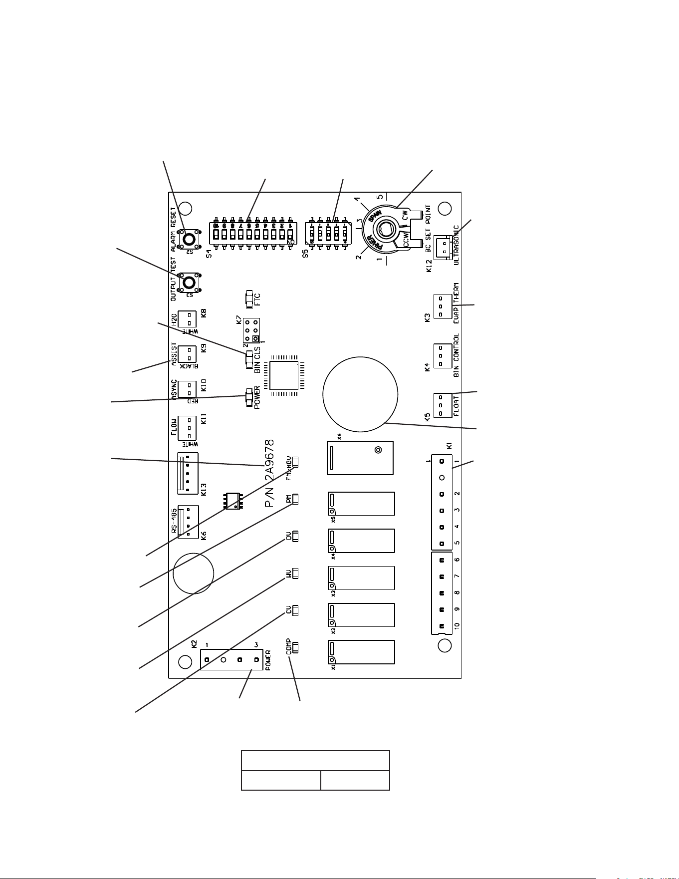
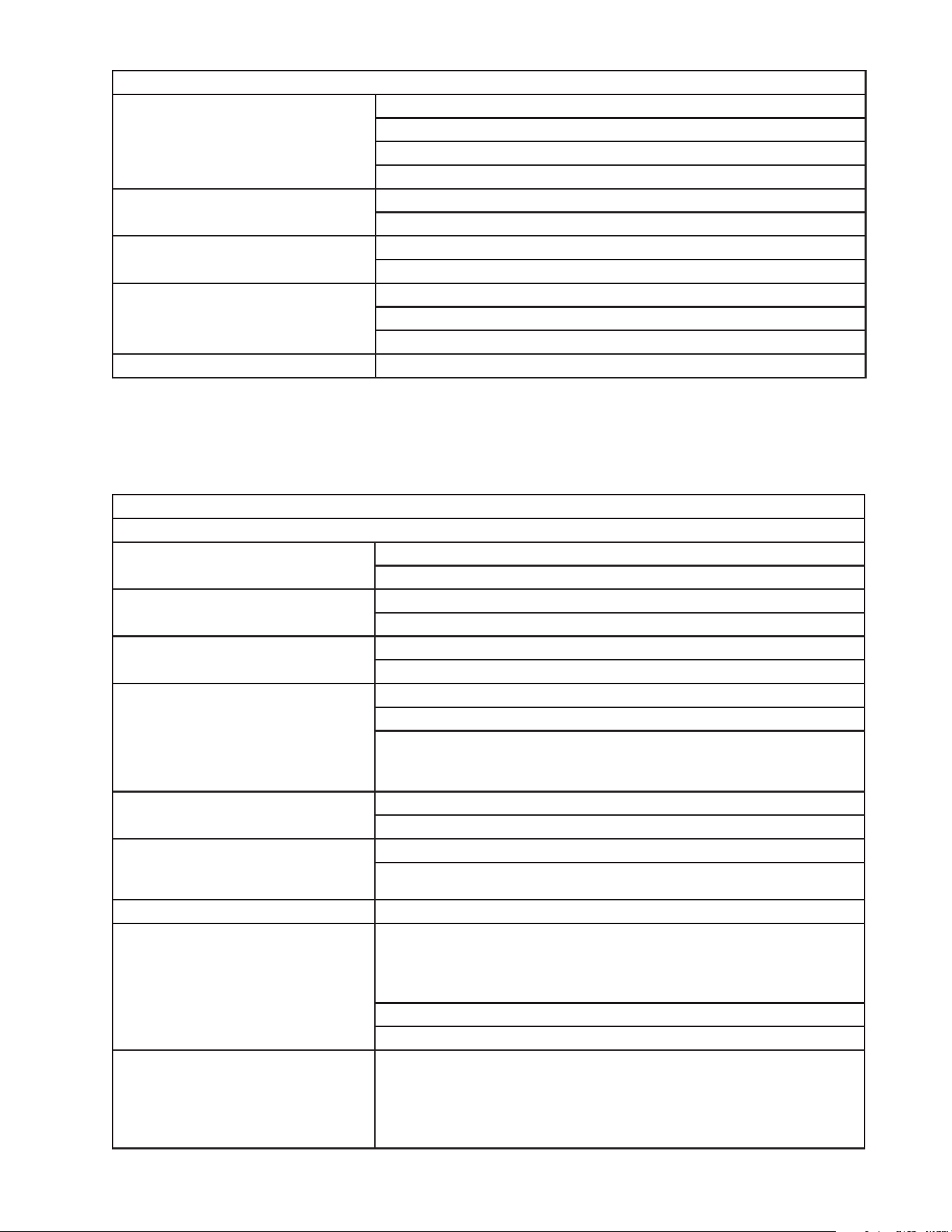
38
A. Control Board Layout
Control Board
Control Board
Part Number 2A9678-01
• Bin Control Switch
BIN CLS LED (orange)
• PM LED (X5 Relay)
K1 Connector Pin #4
• DV LED (X4 Relay)
K1 Connector Pin #5
• CV LED (X2 Relay)
K1 Connector Pin #9
• COMP LED (X1 Relay)
K1 Connector Pin #1
• K2 Connector
Control Transformer
(10.5VAC)
• "ALARM RESET" Button (white)
• S4 Dip Switch
• "OUTPUT TEST"
Button
(used to test relays on
control board)
• K3 (white) Connector
(5VDC)
Thermistor
(harvest control and high
temperature safety)
• K5 (black) Connector (2VDC)
Float Switch
• Part Number
• Alarm Buzzer
• Relay LEDs
(6) (indicate which
relays are energized
and which K1
connector pins are
energized
• POWER LED
(red) (lights when
10.5VAC is supplied
to K2 connector)
• K9 (black)
(Cleaning and
Sanitizing Circuit)
• WV LED (X3 Relay)
K1 Connector Pin #6
• S5 Dip Switch
• HGV LED (X6 Relay)
K1 Connector Pin #2
• K12 (white) Connector (5VDC)
Ultrasonic Bin Control
• Ultrasonic Bin Control
Distance Adjustment
-01
• K1 Connector
Pins #1 through #10
#1 Compressor Relay,
Crankcase Heater Relay,
Remote Condenser
Fan Motor
#2 Hot Gas Valve
#3 Fan Motor,
Liquid Line Valve
#4 Pump Motor
#5 Drain Valve
#6 Inlet Water Valve
#7, 8 Open
#9 Cleaning Valve
#10 Control Board Power
Supply
39
B. LED Lights and Audible Alarm Safeties
An audible beep occurs and red CB "POWER" LED turns on when control switch is
moved to "ICE" position.
Sequence
Green LEDs turn on and sequence from initial startup as listed in the table below. Order
of green LEDs from the outer edge of control board is Comp, CV, WV, DV, PM, FM/HGV.
Sequence Step LED
Energized
Components
Time LEDs are On
Min. Max.
1-Minute Fill Cycle WV WV
Harvest Cycle Comp, WV, **FM/HGV Comp, FMR, HGV, WV 1 minute 20 minutes
Harvest Pump Time
(harvest assist)
Comp, PM, **FM/HGV Comp, FMR, HGV, PM 0 seconds 50 seconds
Freeze Cycle Comp, PM Comp, FM/FMR, PM, LLV 5 minutes freeze timer
setting
Anti-Slush Control Comp Comp, FM/FMR, LLV PM off 10 sec. when
thermistor at 36°F (2°C)
Pump-Out Cycle Comp, PM, **FM/HGV,
DV, *WV
Comp, FMR, HGV, PM, *WV, DV 10 seconds 20 seconds
*pump-out timer setting **FM is OFF when FM/HGV is ON
Alarms
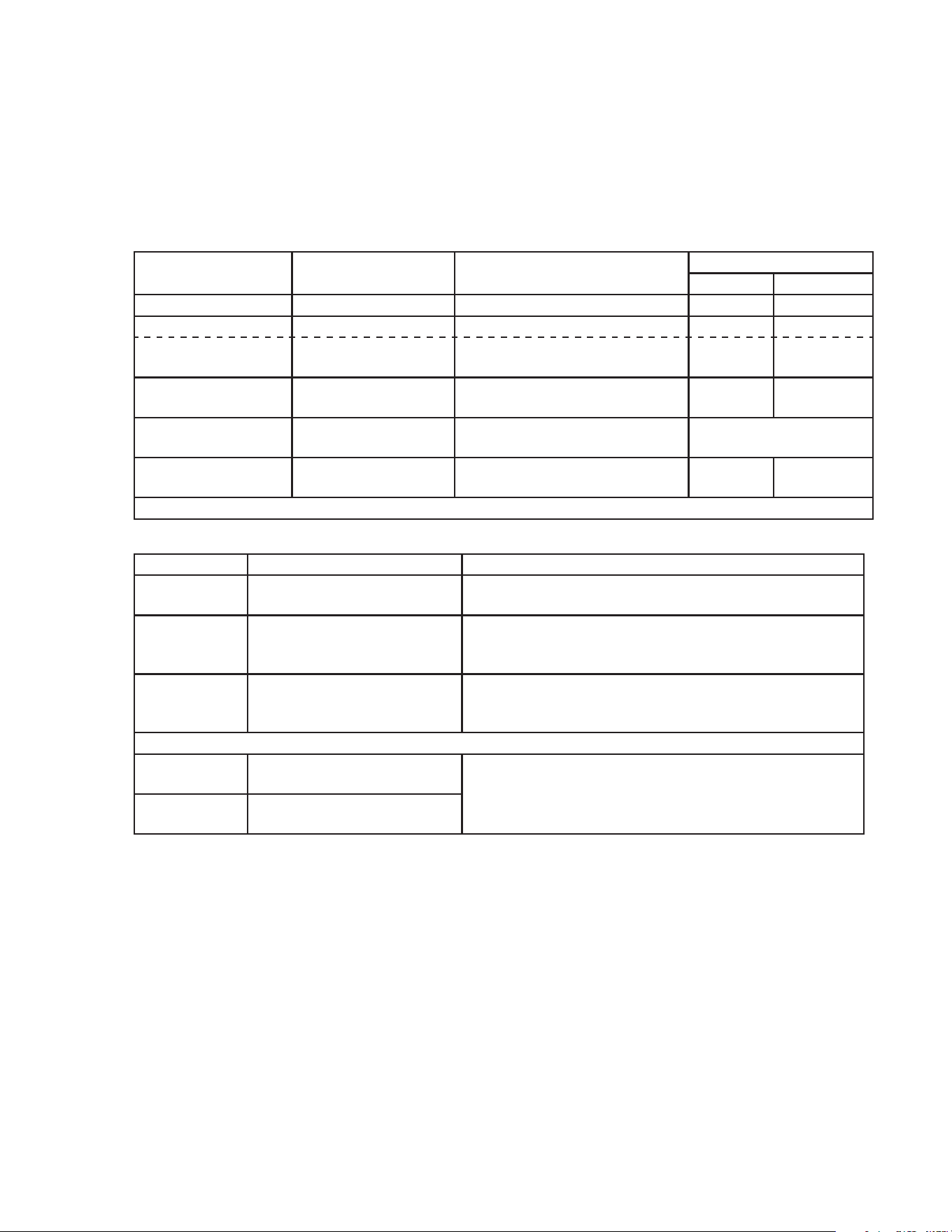
Type Alarm Notes
1
Beep
High Evaporator Temp.
(temperature > 127°F) (53°C)
Check for harvest problem (stuck HGV or relay),
hot water entering unit, stuck HM, or shorted thermistor.
2
Beep
Harvest Backup Timer
(harvest > 20 min. for two
cycles in a row)
Check thermistor (open), HGV not opening, TXV or LLV
leaking by, low charge, inefficient Comp, or WRV leaking
by.
3
Beep
Freeze Timer
(freeze > freeze timer setting
for two cycles in a row)
Check FS stuck closed (up), WV leaking by, HGV leaking
by, PM not pumping, TXV defective, LLV not opening, low
charge, HMnot bypassing, or inefficient Comp.
To reset above safeties, press "ALARM RESET" button with power supply on.
6 Low Voltage
(92Vac±5% or less)
Red LED turns off if voltage protection operates.
Control voltage safeties automatically reset when voltage
is corrected.
7 High Voltage
(147Vac±5% or more)
Legend: Comp–compressor; CV–cleaning valve; DV–drain valve; FM–fan motor;
FMR–fan motor remote; FS–oat switch; HGV–hot gas valve; HM–headmaster
(C.P.R.); L LV–liquid line valve; PM–pump motor; TXV–thermostatic expansion
valve; WRV–water regulating valve; WV–inlet water valve
40
C. Settings and Adjustments
NOTICE
Dip switches are factory set. Failure to maintain factory settings may adversely
affect performance and warranty coverage. For more information, contact your
Hoshizaki Service Center.
1. Default Dip Switch Settings
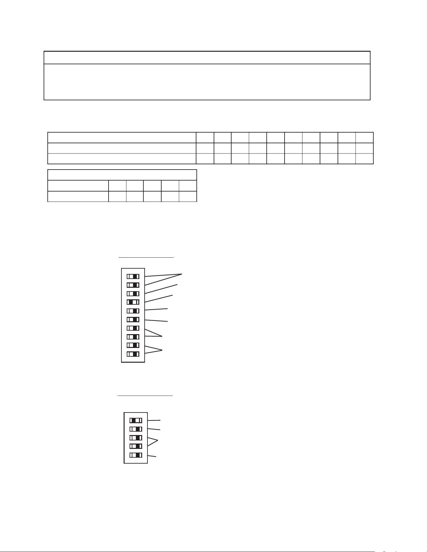
The dip switches are factory-adjusted to the following positions:
S4 Dip Switch No. 1 2 3 4 5 6 7 8 9 10
KMD-505MAJ, KMD-505MWJ, KMD-505MRJZ OFF OFF OFF OFF OFF OFF ON OFF OFF OFF
KMD-705MAJ, KMD-705MWJ, KMD-705MRJZ OFF OFF OFF OFF OFF OFF ON OFF OFF OFF
S5 Dip Switch (Do Not Adjust)
Dip Switch No.
1 2 3 4 5
All Models OFF OFF OFF OFF ON
Freeze Timer (9 & 10)
Pump-Out Frequency Control (5)
Pump-Out Time/Harvest Time During Pump-Out (3 & 4)
Harvest Time (1 & 2)
Factory Use (8)
Harvest Pump Time (Harvest Assist (7) (Do Not Adjust)
1 2 3 4 5 6 7 8 9 10
ON
S4 Dip Switch
1 2 3 4 5
ON
S5 Dip Switch
(Do Not Adjust)
Rell Counter (2 and 3)
Float Switch Selector (1)
Minimum Harvest Time (4)
Anti-Slush (5)
Harvest Pump Time (Harvest Assist) (6) (Do Not Adjust)
41
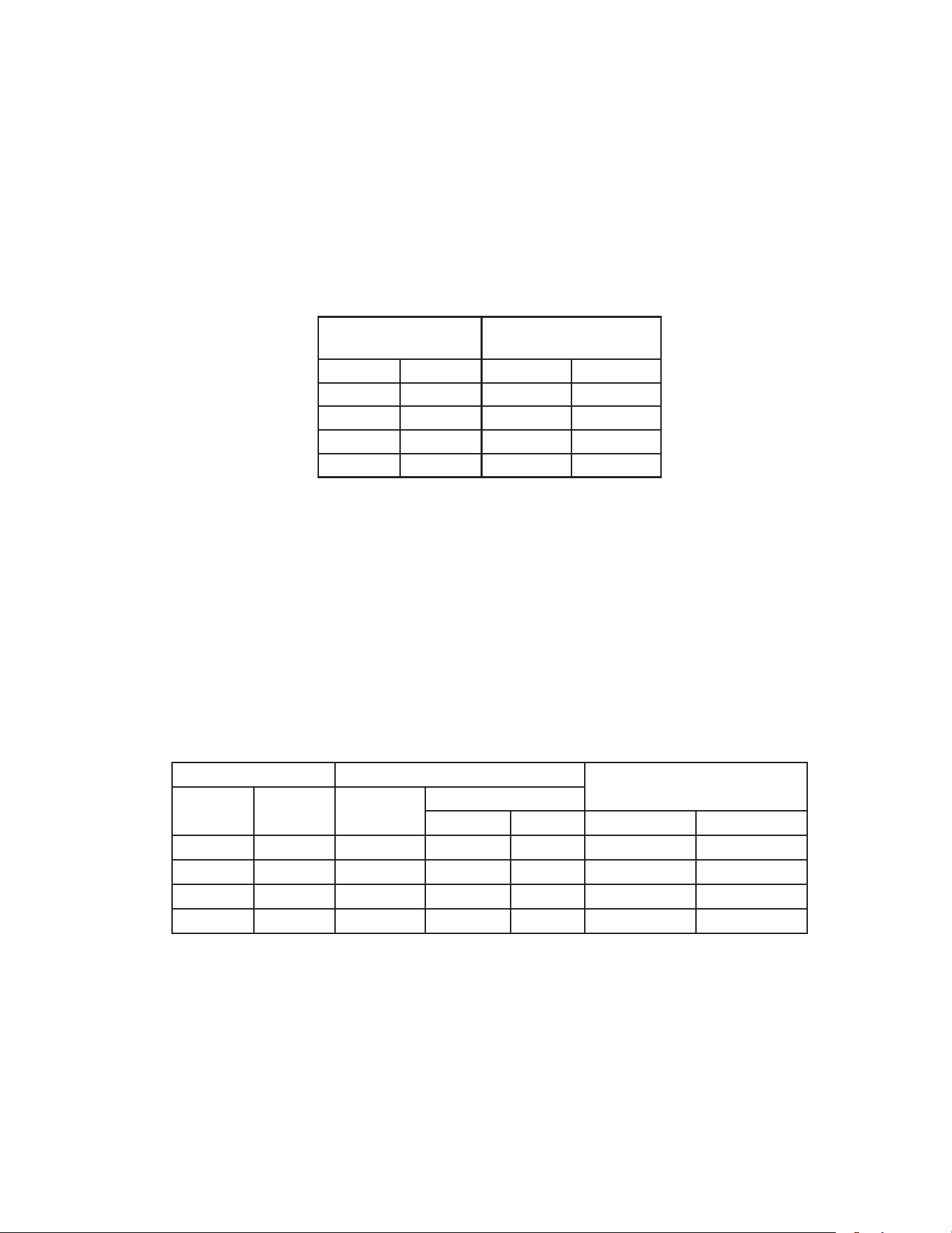
2. Harvest Time (S4 dip switch 1 & 2)
The harvest timer starts counting when the thermistor reaches 48°F (9°C) at the
evaporator outlet and the control board reads 3.9 kΩ from the thermistor. The harvest
timer is factory set, and generally no adjustment is required. However, a setting longer
than the factory setting may be advised in cases where the drain provided at harvest
needs to be prolonged for extra cleaning. Note that the pump-out timer (S4 dip switch
3&4) acts in place of the harvest timer during cycles with a pump out.
For details, see "III.C.3. Pump-Out Timer (S4 dip switch 3& 4)."
Note: On models with a pump-out every cycle, the harvest timer is only relevant during
the initial harvest cycle since a pump out occurs every cycle thereafter.
S4 Dip Switch Setting
Time
(sec.)
No. 1 No. 2 S5-4 OFF S5-4 ON
OFF OFF 60 30
ON OFF 90 45
OFF ON 120 60
ON ON 180 75
3. Pump-Out Time/Harvest Time During Pump-Out (S4 dip switch 3 & 4)
When a pump-out is called for, the pump motor stops for 2 sec. After 2 sec. the drain
valve and pump motor energize. Water is removed from the bottom of the water tank
and sent down the drain. The pump-out drains the water tank for the time determined by
the pump-out timer. The pump-out timer also acts in place of the harvest timer during
cycles with a pump-out. The pump-out timer is factory set, and generally no adjustment
is required. However, where water quality is bad and the icemaker needs a longer
pump-out time, the pump-out timer can be adjusted. The pump-out timer control can be
set to pump-out for 10 or 20 sec. During pump-out cycles minimum harvest time is based
on times given in the
table below.
S4 Dip Switch Setting Time (sec.)
Inlet Water
Valve
No. 3 No. 4
T1 T2
S5-4 OFF S5-4 ON S5-4 OFF S5-4 ON
OFF OFF 10 150 100 Closed Closed
ON OFF 10 180 130 Closed Closed
OFF ON 10 120 70 Open Closed
ON ON 20 180 180 Closed Closed
T1: Time to drain the water tank
T2: Harvest timer at pump out
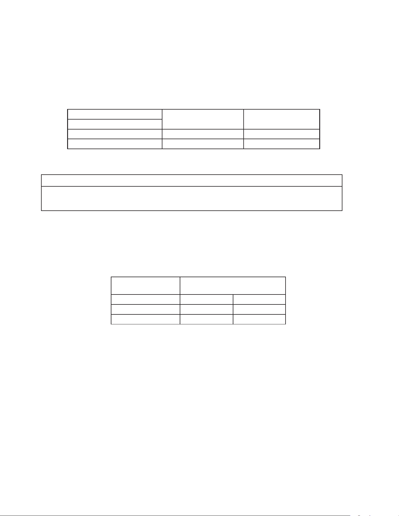
42
4. Pump-Out Frequency Control (S4 dip switch 5)
The pump-out frequency control is factory set to drain the water tank every 10 cycles.
Generally no adjustment is required. However, where water quality is bad and the
icemaker needs a pump-out more often, the pump-out frequency can be adjusted.
The pump-out frequency control can be set to have a pump-out occur every cycle, or
every10 cycles.
The rst pump-out is dependent on S4 dip switch 5. See the table below.
S4 Dip Switch Setting
Pump-Out Frequency 1st Pump-Out
No. 5
OFF Every 10 cycles After 11th freeze cycle
ON Every cycle After 2nd freeze cycle
5. Harvest Pump Time (Harvest Assist) (S4 dip switch 6)
NOTICE
Factory set for proper operation. Do not adjust. Adjustment outside of the factory
default setting may result in damage to the appliance.
Harvest pump time (harvest assist) is only active when S4 dip switch 7 is in the "ON"
position. In the factory default position, the harvest pump time (harvest assist) starts with
50sec. left to go in harvest cycle (S4 dip switch 6) and after the thermistor reaches
48°F (9°C) at the evaporator outlet and the control board reads 3.9kΩ from the
thermistor. The harvest pump time (harvest assist) is factory set, and no adjustment is
required.
S4 Dip Switch Setting
Harvest Pump Time
(Harvest Assist)
No. 6 S5-4 OFF S5-4 ON
OFF 50 sec. 25 sec.
ON 25 sec. 15 sec.
43
6. Harvest Pump Time (Harvest Assist (S4 dip switch 7))
NOTICE
Factory set for proper operation. Do not adjust. Adjustment outside of the factory
default setting may result in damage to the appliance.
Depending on S4 dip switch 7 setting, the pump motor either stays off or is energized
during the last seconds of the harvest cycle. When the pump motor is energized (S4 dip
switch 7 on), water circulates over the evaporator. The harvest water valve is open during
harvest for a maximum of 6 minutes or the length of harvest minus the harvest pump
time value(S4 dip switch 6), whichever is shorter.
When S4 dip switch 7 is in the on position and harvest begins, 50 sec. before harvest
termination, WV LED turns off. Next, PM LED turns on and control board K1connector
pin #4 (R) energizes, energizing the pump motor for the last seconds of harvest. Harvest
pump time adjusted by S4 dip switch 1 & 2 and S5 dip switch 4settings. Contact
Hoshizaki Technical Support at 1-800-233-1940 before adjusting these settings.
S4 Dip Switch Setting Harvest Pump
Time (sec.)
(Harvest Assist)No. 7
OFF 0
ON 50
7. Factory Use (S4 dip switch 8)
Factory set for proper operation. Do not adjust. This must be left in the factory default
position.
8. Freeze Timer (S4 dip switch 9 & 10)
NOTICE
Adjust to proper specication, or the icemaker may not operate correctly.
The freeze timer setting determines the maximum allowed freeze time to prevent possible
freeze-up issues. Upon termination of the freeze timer, the control board initiates the
harvest cycle or pump-out cycle. After 2 consecutive freeze timer terminations, the
control board shuts down the icemaker. In this case, see "II.I.3. Low Ice Production"
for possible solutions. The freeze timer is factory set and no adjustment is required.
Before changing this setting, contact Hoshizaki Technical Support at 1-800-233-1940 for
recommendations.
S4 Dip Switch Setting Time
(min.)
No. 9 No. 10
OFF OFF 60
OFF ON 50
ON OFF 70
ON ON 75
44
9. Float Switch Selector (S5 dip switch 1)
NOTICE
Do not adjust. This must be left in the factory default position or the icemaker will
not operate correctly.
This dip switch setting allows use of this control board in single and dual oat switch
models. This model uses a single oat switch style.
S5 Dip Switch Setting
Top or Bottom Float Switch Control
No. 1
OFF Bottom Float Switch Enabled
ON Top Float Switch Enabled
10. Rell Counter (S5 dip switch 2 and 3)
NOTICE
Do not adjust. These must be left in the factory default position or the icemaker will
not operate correctly.
S5 Dip Switch Setting Rell
Counter
No. 2 No. 3
OFF OFF 0
OFF ON 1 rell
ON OFF 9 rells
ON ON 10 rells
11. Minimum Harvest Time (S5 dip switch 4)
NOTICE
Factory set for proper operation. Do not adjust. Adjustment outside the factory
default setting may result in damage to the appliance.
S5 Dip Switch Setting Minimum
Harvest Timer
No. 4
OFF 120 sec.
ON 70 sec.
45
12. Anti-Slush (S5 dip switch 5)
This dip switch setting provides anti-slush control during the freeze cycle. When the
evaporator temperature reaches 36°F (2.2°C) the control board reads a 5.8 kΩ signal
from the thermistor and de-energizes the water pump for 10 sec. to prevent slush from
blocking the water supply tubing, causing irregular freeze patterns.
NOTICE
Factory set for proper operation. Do not adjust. Adjustment outside the factory
default setting may result in damage to the appliance.
S5 Dip Switch Setting
Anti-SlushNo. 5
OFF Disabled
ON Enabled
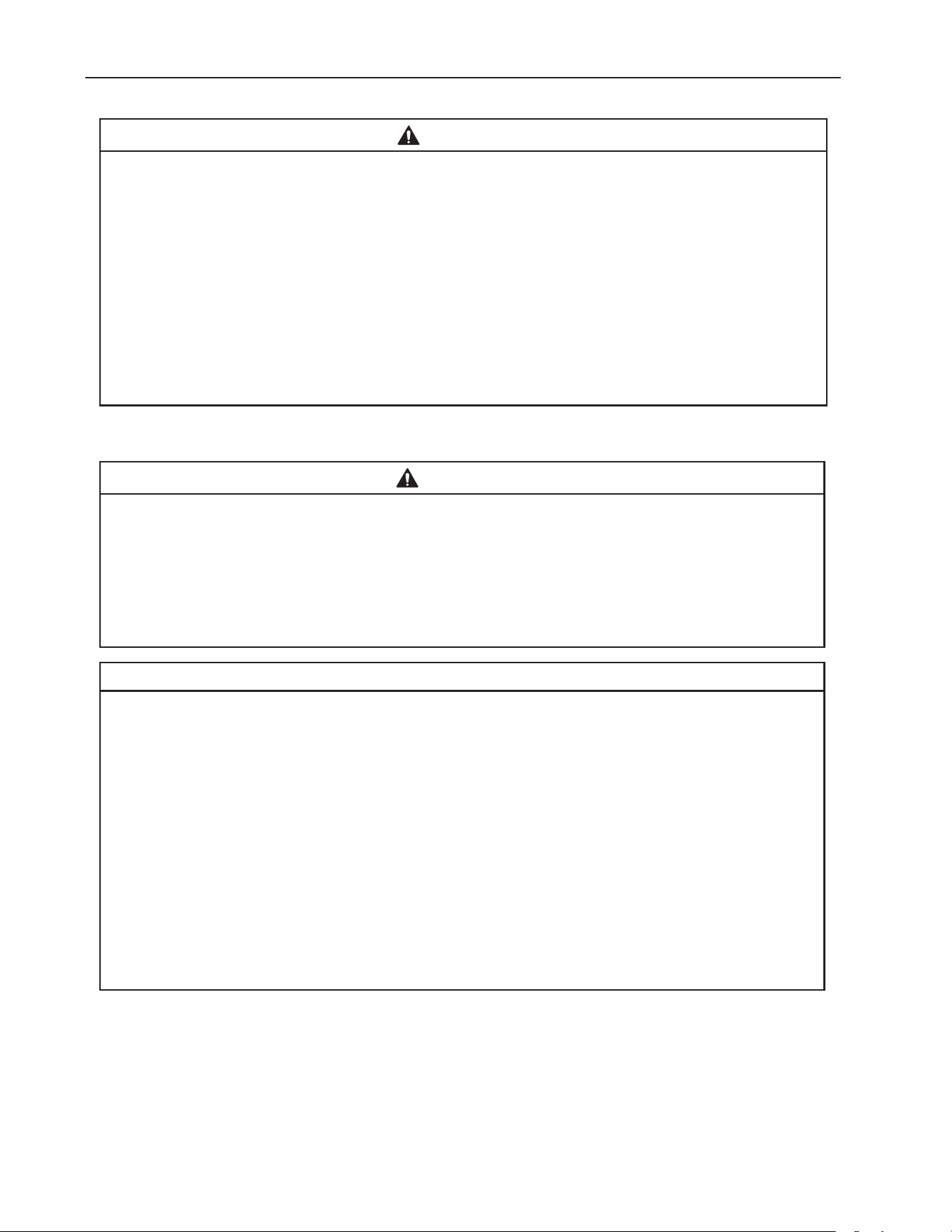
46
IV. Refrigeration Circuit and Component Service Information
WARNING
• This appliance should be diagnosed and repaired only by qualied service
personnel to reduce the risk of death, electric shock, serious injury, or re.
• Move the control switch to the "OFF" position and turn off the power supply. Place
the disconnect in the "OFF" position. Lockout/Tagout to prevent the power supply
from being turned back on inadvertently.
• CHOKING HAZARD: Ensure all components, fasteners, and thumbscrews are
securely in place after the icemaker is serviced. Make sure that none have fallen
into the dispenser unit/ice storage bin.
• Make sure all food zones in the icemaker and dispenser unit/ice storage bin are
clean after service.
A. Refrigeration Circuit Service Information
WARNING
• Repairs requiring the refrigeration circuit to be opened must be performed by
properly trained and EPA-certied service personnel.
• Use an electronic leak detector or soap bubbles to check for leaks. Add a trace of
refrigerant to the system (if using an electronic leak detector), and then raise the
pressure using nitrogen gas (140 PSIG). Do not use R-404A as a mixture with
pressurized air for leak testing.
NOTICE
• Always recover the refrigerant and store it in an approved container. Do not
discharge the refrigerant into the atmosphere.
• Do not leave the system open for longer than 15 min. when replacing or servicing
parts. The Polyol Ester (POE) oils used in R-404A applications can absorb
moisture quickly. Therefore it is important to prevent moisture from entering the
system when replacing or servicing parts.
• Always install a new drier every time the sealed refrigeration system is opened.
Do not replace the drier until after all other repair or replacement has been made.
Install the new drier with the arrow on the drier in the direction of the refrigerant
ow.
• When brazing, protect the drier by using a wet cloth to prevent the drier from
overheating. Do not allow the drier to exceed 250°F (121°C).
1. Refrigerant Recovery
The icemaker is provided with refrigerant access valves. Using proper refrigerant practices,
recover the refrigerant. Store the refrigerant in an approved container. Do not discharge the
refrigerant into the atmosphere.
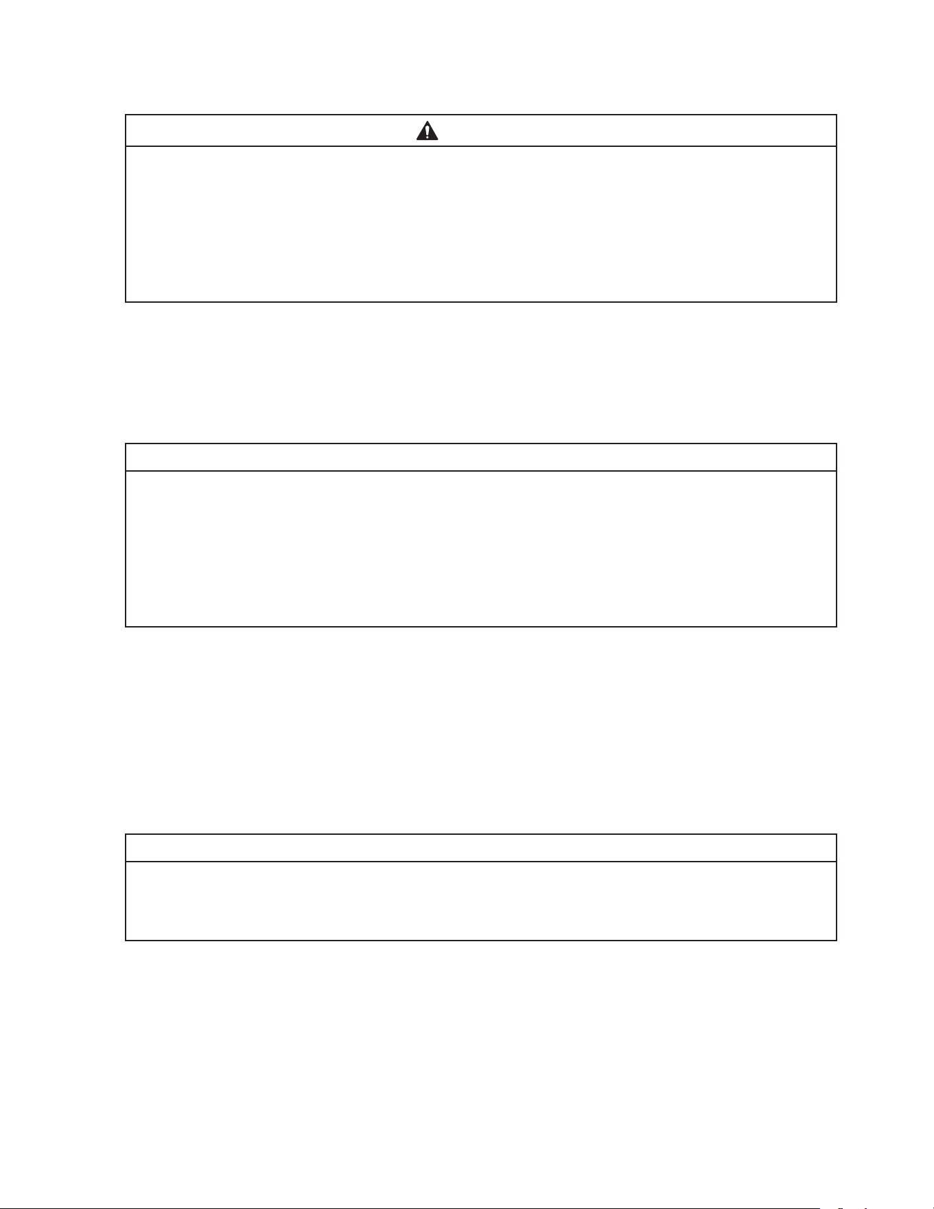
47
2. Brazing
WARNING
• R-404A itself is not ammable at atmospheric pressure and temperatures up to
176°F (80°C).
• R-404A itself is not explosive or poisonous. However, when exposed to high
temperatures (open ames), R-404A can be decomposed to form hydrouoric
acid and carbonyl uoride both of which are hazardous.
• Do not use silver alloy or copper alloy containing arsenic.
1) Braze all ttings while purging with nitrogen gas owing at a pressure of 3 to 4 PSIG.
Note: Because the pipes in the evaporator case are specially coated to resist corrosion,
it is important to make connections outside the evaporator case when possible.
If it is necessary to braze inside the evaporator case, use sandpaper to remove
the coating from the brazing connections before unbrazing the components.
NOTICE
• Always install a new drier every time the sealed refrigeration system is opened.
• Do not replace the drier until after all other repair or replacement has been made.
Install the new drier with the arrow on the drier in the direction of the refrigerant
ow.
• When brazing, protect the drier by using a wet cloth to prevent the drier from
overheating. Do not allow the drier to exceed 250°F (121°C).
2) Use an electronic leak detector or soap bubbles to check for leaks. Add a trace of
refrigerant to the system (if using an electronic leak detector), and then raise the
pressure using nitrogen gas (140 PSIG). Do not use R-404A as a mixture with
pressurized air for leak testing.
3. Evacuation and Recharge (R-404A)
1) Attach a vacuum pump to the system. Be sure to connect the charging hoses to both
high and low-side refrigerant access valves.
IMPORTANT
The vacuum level and vacuum pump may be the same as those for current
refrigerants. However, the rubber hose and gauge manifold to be used for
evacuation and refrigerant charge should be exclusively for POE oils.
2) Turn on the vacuum pump. Open the gauge manifold valves. Never allow the oil in the
vacuum pump to ow backwards.
3) Allow the vacuum pump to pull down to a 29.9" Hg vacuum. Evacuating period depends
on pump capacity.
4) Close the low-side valve and high-side valve on the gauge manifold.

48
5) Disconnect the gauge manifold hose from the vacuum pump and attach it to a
refrigerant service cylinder. Remember to loosen the connection and purge the air from
the hose. For the required refrigerant charge, see the rating label inside the icemaker.
Hoshizaki recommends only virgin refrigerant or reclaimed refrigerant which meets
AHRI Standard 700 (latest edition) be used.
6) A liquid charge is required when charging an R-404A system (to prevent fractionation).
Place the service cylinder on the scales; if the service cylinder is not equipped with
a dip tube, invert the service cylinder, then place it on the scales. Open the high-side
valve on the gauge manifold.
7) Allow the system to charge with liquid until the proper charge weight is met.
8) If necessary, add any remaining charge to the system through the low-side.
NOTICE!To prevent compressor damage, use a throttling valve or liquid
dispensing device to add the remaining liquid charge through the low-side
refrigerant access valve with the icemaker running.
9) Close the high and low-side gauge manifold valves, then disconnect the gauge manifold
hoses.
10) Cap the refrigerant access valves to prevent a possible leak.
49
B. Component Service Information
NOTICE
When replacing a component listed below, see the notes to help ensure proper
operation.
Component Notes
Compressor 1 phase: Install a new start capacitor, run capacitor, and start relay.
Thermostatic
Expansion Valves
• Attach the thermostatic expansion valve bulb to the suction line in the same location as
the previous bulb.
• The bulb should be between the 10 and 2 o'clock positions on the tube.
• Secure the bulb with the clamp and holder, then insulate it.
Hot Gas Valves
Liquid Line
Valves
• Replace the strainer if applicable.
• Use copper tube of the same diameter and length when replacing valve lines.
Fan Motors Install a new capacitor.
Pump Motor Install a new capacitor.
Thermistor • Replace with Service Kit SP-5672. Follow instructions in kit.
C. Water Regulating Valve Adjustment (water-cooled model)
The water regulating valve is factory set, and generally no adjustment is required. However,
when necessary, adjust the water regulator using the following procedure.
1) Prepare a thermometer to check the condenser drain temperature. Attach a pressure
gauge to the high-side line of the system.
2) 5 min. after a freeze cycle starts, conrm
that the thermometer reads 104°F to 115°F
(40°C to 46°C). If it does not, rotate the
adjustment screw by using a at blade
screwdriver until the temperature is in the
proper range. See Fig. 9. Next, check that
the reference pressure is in the range
indicated in the Head Pressure table in the
Performance Data section. If it is not in the
proper range, verify the refrigerant charge.
3) Check that the condenser drain temperature is stable.
Fig. 9
Adjustment Screw
CW – Higher
CCW – Lower
Top View
50
V. Maintenance
The maintenance schedule below is a guideline. More frequent maintenance may be
required depending on water quality, the appliance's environment, and local sanitation
regulations
WARNING
• Only qualied service technicians should service the appliance.
• To reduce the risk of electric shock, do not touch the control switch or service
switch with damp hands
• Before servicing: Move the control switch to the "OFF" position and turn off the
power supply. Place the disconnect in the "OFF" position.
Lockout/Tagout to prevent the power supply from being turned back on
inadvertently.
• CHOKING HAZARD: Ensure all components, fasteners, and thumbscrews are
securely in place after any maintenance is done to the icemaker. Make sure that
none have fallen into the dispenser unit/ice storage bin.
Maintenance Schedule
Frequency Area Task
Daily Scoop Clean the ice scoop using a neutral cleaner. Rinse thoroughly after
cleaning.
Bi-Weekly Air Filters Inspect. Wash with warm water and neutral cleaner if dirty.
Monthly External Water
Filters
Check for proper pressure and change if necessary.
Ultrasonic Bin
Control Lens
Wipe down the ultrasonic bin control lens, (located on the bottom of the
icemaker) with a neutral cleaner. Rinse thoroughly after cleaning.
Icemaker Exterior Wipe down with a clean, soft cloth. Use a damp cloth containing a
neutral cleaner to wipe off oil or dirt build up. Clean any chlorine staining
(rust colored spots) using a non-abrasive cleanser.
Underside of
Icemaker and Top
Kits; Bin Door and
Snout
Wipe down with a clean cloth and warm water.
Yearly Icemaker and
Dispenser Unit/Ice
Storage Bin Liner
Clean and sanitize per the cleaning and sanitizing instructions provided
in the instruction manual or maintenance label on the icemaker.
Water Supply Inlet Close the icemaker water supply line shut-off valve and drain the water
system. Clean the water supply inlet screen.
Condenser Inspect. Clean if necessary by using a brush or vacuum cleaner. More
frequent cleaning may be required depending on location.
Water Hoses Inspect the water hoses and clean/replace if necessary.
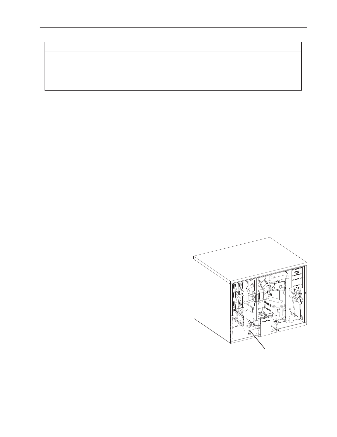
51
VI. Preparing the Appliance for Periods of Non-Use
NOTICE
• When storing the appliance for an extended time or in sub-freezing temperatures,
follow the instructions below to prevent damage.
• To prevent damage to the water pump, do not operate the appliance with the
control switch in the "PUMP" position when the water tank is empty.
When the appliance is not used for two or three days under normal conditions, it is
sufficient to move the control switch to the "OFF" position. When storing the appliance for
an extended time or in sub-freezing temperatures, follow the instructions below.
1. Remove the water from the icemaker water line:
1) Turn off the power supply, then remove the front panel.
2) Close the icemaker water supply line shut-off valve and open the icemaker water supply
line drain valve.
3) Allow the line to drain by gravity.
4) Attach a compressed air or carbon dioxide supply to the icemaker water supply line
drain valve.
5) Make sure at least 3 min. have elapsed since you turned off the power supply. Make
sure the control switch is in the "ICE" position. Replace the front panel in its correct
position, then turn on the power supply.
6) Blow the icemaker water supply line out using the compressed air or carbon dioxide
supply.
7) Close the icemaker water supply line drain valve.
2. Remove the water from the water tank:
1) Turn off the power supply, then remove the
front panel.
2) Move the control switch to the "OFF" position.
3) Remove the front insulation panel, remove
the drain plug in the bottom of the water
tank. See Fig. 10. After the water tank has
drained, replace the drain plug.
4) Replace the front insulation panel and the
front panel in their correct positions.
5) Remove all ice from the dispensing unit/ice storage bin.
Clean the storage bin liner using a neutral cleaner. Rinse thoroughly after cleaning.
Drain Plug
Fig. 10

52
3. On water-cooled model, remove the water from the water-cooled condenser:
1) Make sure the power supply is off, then remove the front panel and right side panel.
2) Close the condenser water supply line shut-off valve. If connected to a closed loop
system, also close the condenser return line shut-off valve.
3) Open the condenser water supply line drain valve. If connected to a closed loop system,
also open the condenser return line drain valve.
4) Attach a compressed air or carbon dioxide supply to the condenser water supply line
drain valve.
5) Open the water regulating valve by using a screwdriver to pry up on the spring retainer
underneath the spring. While holding the valve open, blow out the condenser using the
compressed air or carbon dioxide supply until water stops coming out.
6) Close the drain valve(s).
7) Replace the right side panel and front panel in their correct positions.

53
VII. Disposal
The appliance contains refrigerant and must be disposed of in accordance with
applicable national, state, and local codes and regulations. Refrigerant must be
recovered by properly certied service personnel.
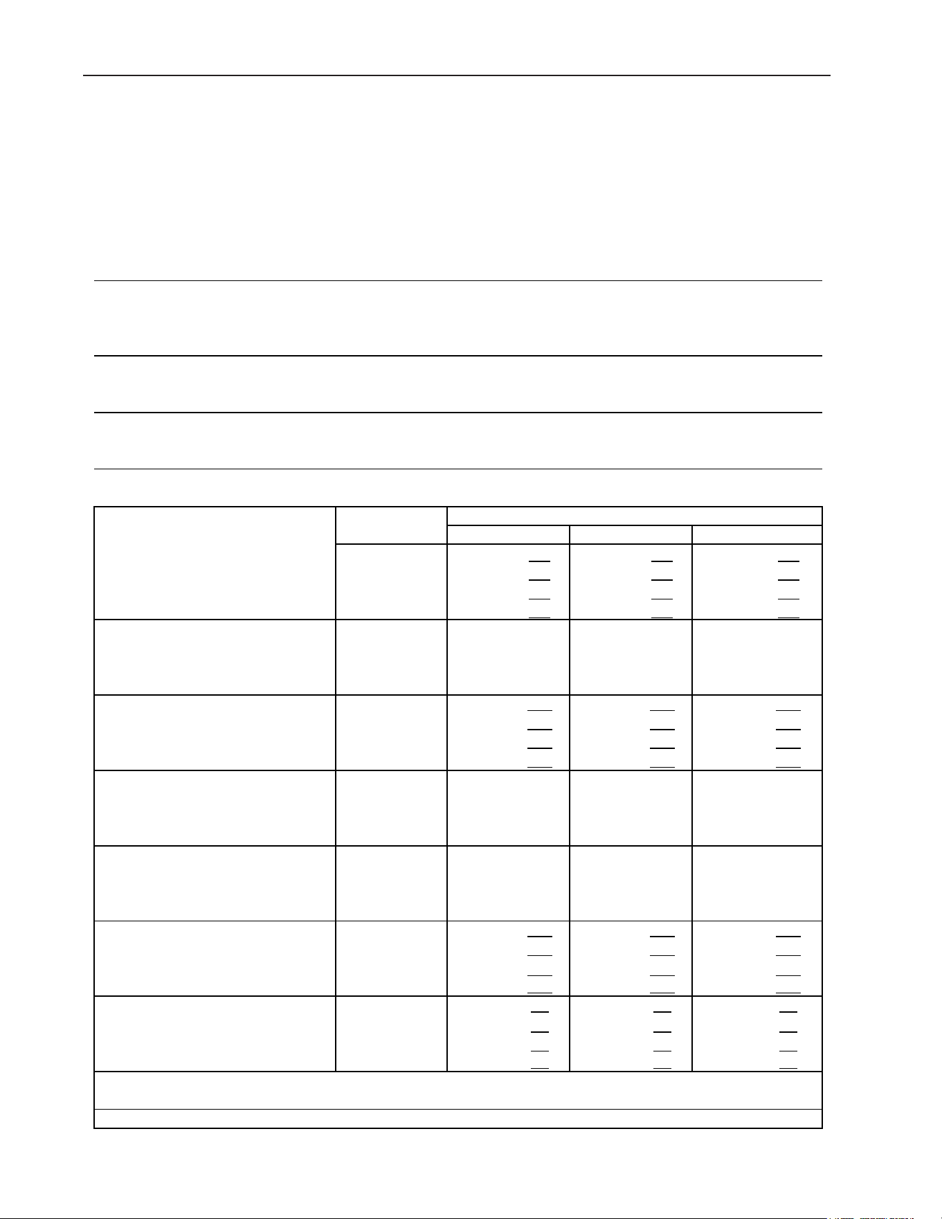
54
VIII. Technical Information
We reserve the right to make changes in specications and design without prior notice.
A. Specication and Performance Data Sheets
Pressure data is recorded at 5 min. into freezing cycle. The data not in bold should be
used for reference only.
1. KMD-505MAJ
Model: KMD-505MAJ
Specification Sheet
AC SUPPLY VOLTAGE 115/60/1
AMPERAGE 10.7 A ( 5 Min. Freeze AT 104°F / WT 100°F)
MINIMUM CIRCUIT AMPACITY 20 A
MAXIMUM FUSE SIZE 20 A
ELECTRIC & WATER CONSUMPTION 90/70°F 70/50°F
ELECTRIC W (kWH/100 lbs.) 960 (5.55) 880 (4.21)
WATER gal./24HR (gal./100 lbs.) 104 (25.0) 259 (51.8)
ICE PRODUCTION PER CYCLE 9.6 lbs. (4.4 kg) 468 pcs.
BIN CONTROL SYSTEM Ultrasonic Sensor
REFRIGERANT CHARGE R404A, 1 lb. 8.7 oz. (700 g)
Performance Data Sheet
70/21 500 227
475 216 429 194
80/27 481 218 442 201 389 176
90/32 475 216 415 188 364 165
lbs./day kg./day 100/38 462 209 403 183 316 143
70/21
80/27
90/32
watts 100/38
70/21 259 0.98
213 0.81 192 0.73
80/27 224 0.85 154 0.58 155 0.59
90/32 213 0.81 104 0.39 95 0.36
gal./day m3/day 100/38 162 0.61 102 0.39 87 0.33
70/21
80/27
90/32
min. 100/38
70/21
80/27
90/32
min. 100/38
70/21 244 17.2
265 18.6 294 20.7
80/27 260 18.3 293 20.6 321 22.6
90/32 265 18.6 316 22.2 345 24.3
PSIG kg/cm2G 100/38 271 19.0 323 22.7 372 26.2
70/21 53 3.7 54 3.8 56 3.9
80/27 54 3.8 56 3.9 58 4.1
90/32 54 3.8 57 4.0 59 4.2
PSIG kg/cm2G 100/38 55 3.8 57 4.0 61 4.3
TOTAL HEAT OF REJECTION FROM CONDENSER 6,000 BTU/h [AT 90ºF (32ºC) / WT 70ºF (21ºC)]
TOTAL HEAT OF REJECTION FROM COMPRESSOR 1,100 BTU/h [AT 90ºF (32ºC) / WT 70ºF (21ºC)]
903 934
898 934 965
27
APPROXIMATE ICE PRODUCTION
PER 24 HR.
APPROXIMATE ELECTRIC
CONSUMPTION
APPROXIMATE WATER
CONSUMPTION PER 24 HR.
FREEZING CYCLE TIME
HARVEST CYCLE TIME
HEAD PRESSURE
SUCTION PRESSURE
AMBIENT TEMP.
(ºF/ºC)
WATER TEMP. (ºF/ºC)
50/10 70/21
903
960
991
909 967 1020
90/32
880
31 34
28 32 37
25 27 30
27 29 33
2.9 2.0 2.0
2.5 2.0 2.0
3.3 2.9 2.8
3.0 2.4 2.5
ENG.F-011.1.0205
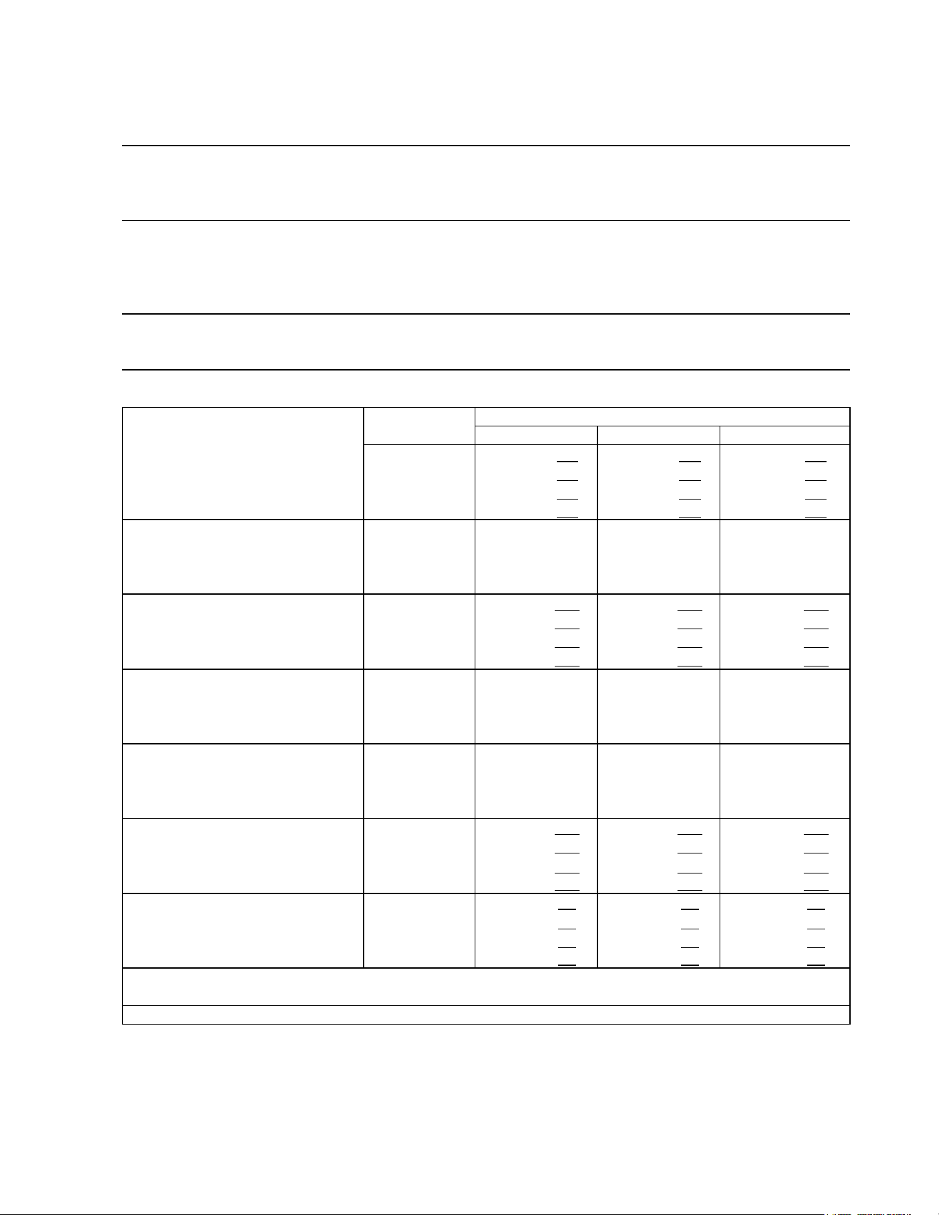
55
2. KMD-505MWJ
Model: KMD-505MWJ
Specification Sheet
AC SUPPLY VOLTAGE 115/60/1
AMPERAGE 11.0 A ( 5 Min. Freeze AT 104°F / WT 100°F)
MINIMUM CIRCUIT AMPACITY 20 A
MAXIMUM FUSE SIZE 20 A
ELECTRIC & WATER CONSUMPTION 90/70°F 70/50°F
ELECTRIC W (kWH/100 lbs.) 960 (4.15) 950 (3.85)
WATER gal./24HR (gal./100 lbs.) 139 (25.0) 258 (43.6)
WATER COOLED CONDENSER 985 (178) 454 (77)
gal./24HR (gal./100 lbs.)
ICE PRODUCTION PER CYCLE 9.6 lbs. (4.3 kg) 468 pcs.
BIN CONTROL SYSTEM Ultrasonic Sensor
REFRIGERANT CHARGE R404A, 0 lb. 15.9 oz. (450 g)
Performance Data Sheet
70/21 592 269
581 264 543 246
80/27 584 265 567 257 516 234
90/32 581 264 555 252 508 231
lbs./day kg./day 100/38 566 257 544 247 466 211
70/21
80/27
90/32
watts 100/38
70/21 712 2.69
833 3.15 1289 4.88
80/27 804 3.04 992 3.75 1609 6.09
90/32 833 3.15 1124 4.26 1683 6.37
gal./day m3/day 100/38 1138 4.31 1255 4.75 2197 8.32
70/21
80/27
90/32
min. 100/38
70/21
80/27
90/32
min. 100/38
70/21 225 15.8
226 15.9 241 16.9
80/27 226 15.9 228 16.1 249 17.5
90/32 226 15.9 230 16.2 248 17.5
PSIG kg/cm2G 100/38 233 16.4 234 16.5 265 18.6
70/21 52 3.7 52 3.7 53 3.7
80/27 52 3.7 52 3.7 53 3.7
90/32 52 3.7 52 3.7 53 3.7
PSIG kg/cm2G 100/38 52 3.7 52 3.7 54 3.8
TOTAL HEAT OF REJECTION FROM CONDENSER 8,600 BTU/h [AT 90ºF (32ºC) / WT 70ºF (21ºC)]
TOTAL HEAT OF REJECTION FROM COMPRESSOR 1,300 BTU/h [AT 90ºF (32ºC) / WT 70ºF (21ºC)]
953 966
952 957 974
21 23 25
22 23 27
21 21 23
21 22 25
APPROXIMATE ICE PRODUCTION
PER 24 HR.
APPROXIMATE ELECTRIC
CONSUMPTION
APPROXIMATE WATER
CONSUMPTION PER 24 HR.
FREEZING CYCLE TIME
HARVEST CYCLE TIME
HEAD PRESSURE
SUCTION PRESSURE
AMBIENT TEMP.
(ºF/ºC)
WATER TEMP. (ºF/ºC)
50/10 70/21
953 960 976
958 964 990
90/32
950
2.6 2.0 2.0
2.3 2.0 2.0
2.8 2.6 2.5
2.6 2.3 2.3
ENG.F-011.1.0205
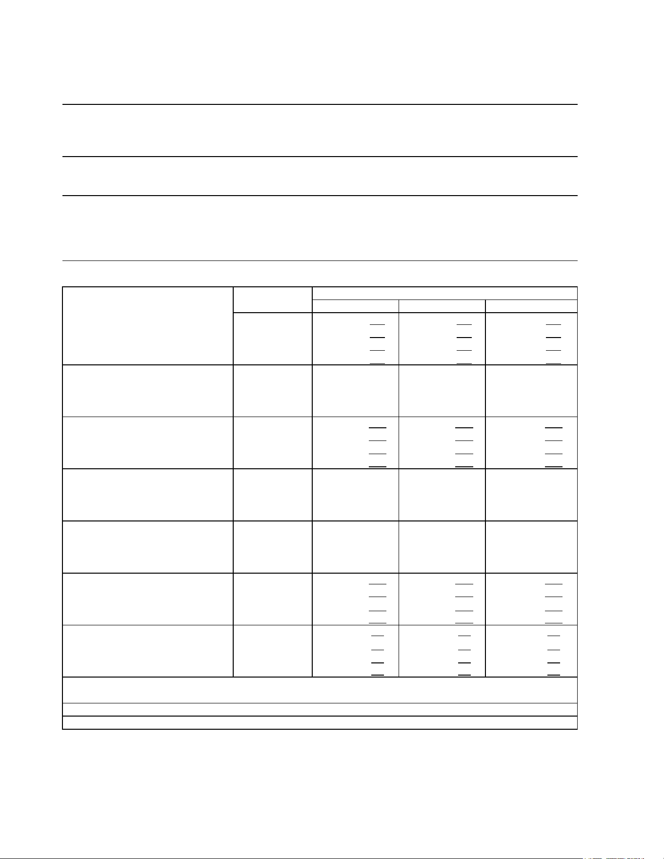
56
3. KMD-505MRJZ with URC-5FZ
Model: KMD-505MRJZ
Specification Sheet
AC SUPPLY VOLTAGE 115/60/1
AMPERAGE 12.4 A ( 5 Min. Freeze AT 104°F / WT 80°F)
MINIMUM CIRCUIT AMPACITY 20 A
MAXIMUM FUSE SIZE 20 A
ELECTRIC & WATER CONSUMPTION 90/70°F 70/50°F
ELECTRIC W (kWH/100 lbs.) 1160 (5.70) 1050 (4.52)
WATER gal./24HR (gal./100 lbs.) 123 (25.0) 246 (44.0)
ICE PRODUCTION PER CYCLE 9.9 lbs. (4.5 kg) 468 pcs.
BIN CONTROL SYSTEM Ultrasonic Sensor
REFRIGERANT CHARGE R404A, 4 lb. 11.8 oz. (2150 g)
ICEMAKER, 2 lb. 13.9 oz. (1300 g)
CONDENSER, 1 lb. 14 oz. (850 g)
Performance Data Sheet
70/21 560 254
539 245 497 225
80/27 544 247 512 232 462 210
90/32 539 245 490 222 442 201
lbs./day kg./day 100/38 526 239 479 217 398 181
70/21
80/27
90/32
watts 100/38
70/21 246 0.93
210 0.79 189 0.72
80/27 218 0.83 162 0.61 157 0.60
90/32 210 0.79 123 0.46 110 0.42
gal./day m3/day 100/38 168 0.63 120 0.45 99 0.38
70/21
80/27
90/32
min. 100/38
70/21
80/27
90/32
min. 100/38
70/21 215 15.1
233 16.4 255 17.9
80/27 229 16.1 257 18.1 277 19.5
90/32 233 16.4 277 19.5 298 21.0
PSIG kg/cm2G 100/38 236 16.6 282 19.8 318 22.4
70/21 51 3.6 52 3.6 53 3.7
80/27 51 3.6 52 3.7 53 3.8
90/32 52 3.6 53 3.7 54 3.8
PSIG kg/cm2G 100/38 52 3.6 53 3.7 55 3.9
TOTAL HEAT OF REJECTION FROM CONDENSER 7,900 BTU/h [AT 90ºF (32ºC) / WT 70ºF (21ºC)]
TOTAL HEAT OF REJECTION FROM COMPRESSOR 1,300 BTU/h [AT 90ºF (32ºC) / WT 70ºF (21ºC)]
CONDENSER VOLUME 44 CU. IN. URC-5FZ
A
PPROXIMATE ICE PRODUCTION PER
24 HR.
APPROXIMATE ELECTRIC
CONSUMPTION
APPROXIMATE WATER
CONSUMPTION PER 24 HR.
FREEZING CYCLE TIME
HARVEST CYCLE TIME
HEAD PRESSURE
SUCTION PRESSURE
AMBIENT TEMP.
(ºF/ºC)
WATER TEMP. (ºF/ºC)
50/10 70/21 90/32
2.7
2.8
3.0 2.7
2.3
2.0
2.0
2.4
1050
1075
1082
24
25
1081
24
23
28
27
24
26
2.0
2.6
2.4
2.0
1108
1141
1181
1200
1082
1125
1160
1165
31
33
27
29
ENG.F-011.1.0205
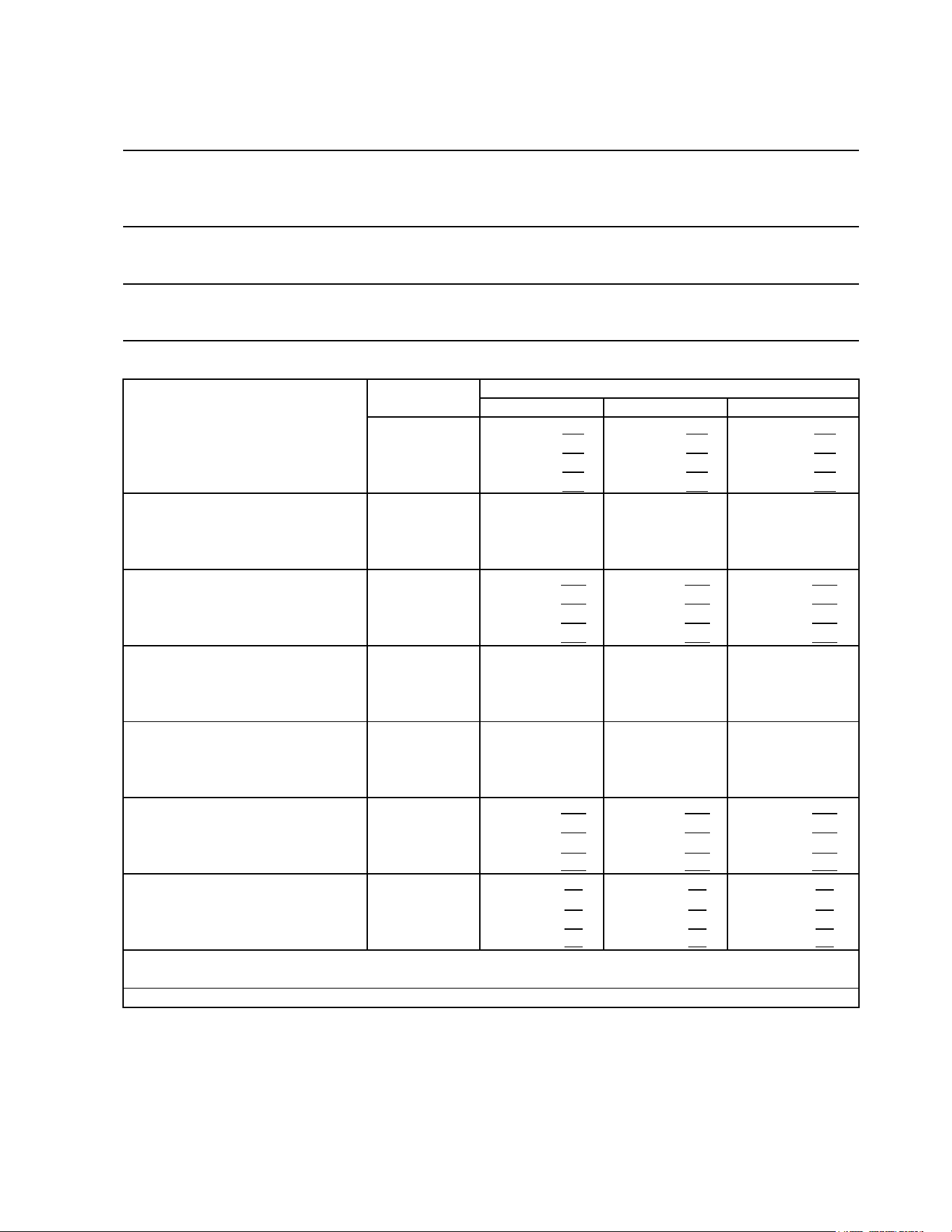
57
4. KMD-705MAJ
Model: KMD-705MAJ
Specification Sheet
AC SUPPLY VOLTAGE 115/60/1
AMPERAGE 14.3 A ( 5 Min. Freeze AT 104°F / WT 100°F)
MINIMUM CIRCUIT AMPACITY 20 A
MAXIMUM FUSE SIZE 20 A
ELECTRIC & WATER CONSUMPTION 90/70°F 70/50°F
ELECTRIC W (kWH/100 lbs.) 1230 (4.75) 1170 (3.88)
WATER gal./24HR (gal./100 lbs.) 136 (22.0) 313 (43.4)
ICE PRODUCTION PER CYCLE 12.9 lbs. (5.9 kg) 624 pcs.
BIN CONTROL SYSTEM Ultrasonic Sensor
REFRIGERANT CHARGE R404A, 2 lb. 12.1 oz. (1250 g)
Performance Data Sheet
70/21 721 327
692 314 643 292
80/27 699 317 653 296 599 272
90/32 692 314 620 281 567 257
lbs./day kg./day 100/38 679 308 608 276 519 235
70/21
80/27
90/32
watts 100/38
70/21 313 1.18
261 0.99 232 0.88
80/27 273 1.03 193 0.73 187 0.71
90/32 261 0.99 136 0.52 120 0.45
gal./day m3/day 100/38 201 0.76 132 0.50 105 0.40
70/21
80/27
90/32
min. 100/38
70/21
80/27
90/32
min. 100/38
70/21 239 16.8
260 18.3 283 19.9
80/27 255 17.9 288 20.2 307 21.6
90/32 260 18.3 311 21.9 332 23.3
PSIG kg/cm2G 100/38 262 18.4 316 22.2 351 24.7
70/21 49 3.4 50 3.5 54 3.8
80/27 50 3.5 52 3.7 56 4.0
90/32 50 3.5 54 3.8 58 4.1
PSIG kg/cm2G 100/38 52 3.6 55 3.9 61 4.3
TOTAL HEAT OF REJECTION FROM CONDENSER 9,400 BTU/h [AT 90ºF (32ºC) / WT 70ºF (21ºC)]
TOTAL HEAT OF REJECTION FROM COMPRESSOR 1,600 BTU/h [AT 90ºF (32ºC) / WT 70ºF (21ºC)]
3.2 2.1 2.0
2.7 2.1 2.0
3.6 3.2 3.0
3.3 2.6 2.6
APPROXIMATE ICE PRODUCTION
PER 24 HR.
APPROXIMATE ELECTRIC
CONSUMPTION
APPROXIMATE WATER
CONSUMPTION PER 24 HR.
FREEZING CYCLE TIME
HARVEST CYCLE TIME
HEAD PRESSURE
SUCTION PRESSURE
AMBIENT TEMP.
(ºF/ºC)
WATER TEMP. (ºF/ºC)
50/10 70/21
1188
1230
1282
1203 1242 1330
90/32
1170 1188 1232
1183 1211 1267
24 27 29
24 28 31
22 24 26
24 26 28
ENG.F-011.1.0205
58
5. KMD-705MWJ
Model: KMD-705MWJ
Specification Sheet
AC SUPPLY VOLTAGE 115/60/1
AMPERAGE 13.0 A ( 5 Min. Freeze AT 104°F / WT 100°F)
MINIMUM CIRCUIT AMPACITY 20 A
MAXIMUM FUSE SIZE 20 A
ELECTRIC & WATER CONSUMPTION 90/70°F 70/50°F
ELECTRIC W (kWH/100 lbs.) 1140 (3.80) 1120 (3.49)
WATER gal./24HR (gal./100 lbs.) 162 (22.5) 275 (35.6)
WATER COOLED CONDENSER 667 (93) 400 (52)
gal./24HR (gal./100 lbs.)
ICE PRODUCTION PER CYCLE 12.5 lbs. (5.7 kg) 624 pcs.
BIN CONTROL SYSTEM Ultrasonic Sensor
REFRIGERANT CHARGE R404A, 1 lb. 11.3 oz. (775 g)
Performance Data Sheet
70/21 773 351
758 344 722 328
80/27 761 345 737 334 694 315
90/32 758 344 720 327 679 308
lbs./day kg./day 100/38 746 338 711 322 642 291
70/21
80/27
90/32
watts 100/38
70/21 675 2.56
720 2.73 938 3.55
80/27 709 2.69 779 2.95 1084 4.10
90/32 720 2.73 829 3.14 1101 4.17
gal./day m3/day 100/38 854 3.23 893 3.38 1351 5.12
70/21
80/27
90/32
min. 100/38
70/21
80/27
90/32
min. 100/38
70/21 270 19.0
270 19.0 273 19.2
80/27 270 19.0 270 19.0 274 19.3
90/32 270 19.0 270 19.0 274 19.2
PSIG kg/cm2G 100/38 271 19.1 271 19.0 277 19.5
70/21 47 3.3 48 3.3 50 3.5
80/27 47 3.3 48 3.4 51 3.6
90/32 48 3.3 49 3.4 52 3.6
PSIG kg/cm2G 100/38 48 3.4 50 3.5 54 3.8
TOTAL HEAT OF REJECTION FROM CONDENSER 9,500 BTU/h [AT 90ºF (32ºC) / WT 70ºF (21ºC)]
TOTAL HEAT OF REJECTION FROM COMPRESSOR 1,500 BTU/h [AT 90ºF (32ºC) / WT 70ºF (21ºC)]
2.8 2.2 2.1
2.5 2.1 2.0
3.1 2.8 2.7
2.9 2.5 2.4
APPROXIMATE ICE PRODUCTION
PER 24 HR.
APPROXIMATE ELECTRIC
CONSUMPTION
APPROXIMATE WATER
CONSUMPTION PER 24 HR.
FREEZING CYCLE TIME
HARVEST CYCLE TIME
HEAD PRESSURE
SUCTION PRESSURE
AMBIENT TEMP.
(ºF/ºC)
WATER TEMP. (ºF/ºC)
50/10 70/21
1126 1140 1150
1128 1142 1160
90/32
1120 1126 1136
1124 1134 1144
21 23 24
22 23 25
21 21 23
21 22 24
ENG.F-011.1.0205
59
6. KMD-705MRJZ with URC-9FZ
Model: KMD-705MRJZ
Specification Sheet
AC SUPPLY VOLTAGE 115/60/1
AMPERAGE 13.7 A ( 5 Min. Freeze AT 104°F / WT 80°F)
MINIMUM CIRCUIT AMPACITY 20 A
MAXIMUM FUSE SIZE 20 A
ELECTRIC & WATER CONSUMPTION 90/70°F 70/50°F
ELECTRIC W (kWH/100 lbs.) 1230 (4.40) 1150 (3.80)
WATER gal./24HR (gal./100 lbs.) 141 (21.0) 303 (41.6)
ICE PRODUCTION PER CYCLE 12.7 lbs. (5.8 kg) 624 pcs.
BIN CONTROL SYSTEM Ultrasonic Sensor
REFRIGERANT CHARGE R404A, 10 lb. 11.1 oz. (4850 g)
ICEMAKER, 6 lb. 12.3 oz. (3070 g)
CONDENSER, 3 lb. 14.8 oz. (1780 g)
Performance Data Sheet
70/21 727 330
710 322 667 302
80/27 714 324 688 312 633 287
90/32 710 322 670 304 619 281
lbs./day kg./day 100/38 694 315 658 298 572 259
70/21
80/27
90/32
watts 100/38
70/21 303 1.15
255 0.97 227 0.86
80/27 266 1.01 193 0.73 185 0.70
90/32 255 0.97 141 0.53 124 0.47
gal./day m3/day 100/38 199 0.75 137 0.52 108 0.41
70/21
80/27
90/32
min. 100/38
70/21
80/27
90/32
min. 100/38
70/21 207 14.6
223 15.6 243 17.1
80/27 219 15.4 243 17.1 263 18.5
90/32 223 15.6 260 18.3 280 19.7
PSIG kg/cm2G 100/38 226 15.9 265 18.6 299 21.0
70/21 47 3.3 48 3.4 51 3.6
80/27 48 3.4 50 3.5 54 3.8
90/32 48 3.4 51 3.6 55 3.8
PSIG kg/cm2G 100/38 49 3.5 52 3.6 58 4.1
TOTAL HEAT OF REJECTION FROM CONDENSER 9,500 BTU/h [AT 90ºF (32ºC) / WT 70ºF (21ºC)]
TOTAL HEAT OF REJECTION FROM COMPRESSOR 1,500 BTU/h [AT 90ºF (32ºC) / WT 70ºF (21ºC)]
CONDENSER VOLUME 116 CU. IN. URC-9FZ
A
PPROXIMATE ICE PRODUCTION PER
24 HR.
APPROXIMATE ELECTRIC
CONSUMPTION
APPROXIMATE WATER
CONSUMPTION PER 24 HR.
FREEZING CYCLE TIME
HARVEST CYCLE TIME
HEAD PRESSURE
SUCTION PRESSURE
AMBIENT TEMP.
(ºF/ºC)
WATER TEMP. (ºF/ºC)
50/10 70/21 90/32
3.1
3.2
3.6 3.1
2.5
2.1
2.1
2.6
1150
1168
1173
23
24
1183
23
22
26
25
23
24
2.0
2.9
2.6
2.0
1212
1247
1272
1310
1173
1204
1230
1240
27
29
25
27
ENG.F-011.1.0205
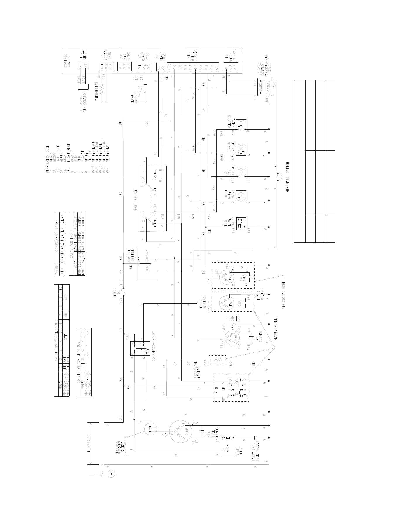
60
B. Wiring Diagram
*
* High-Pressure Switch
Water-Cooled Model Air and Remote Models
Cut-out 384±
22
PSIG 412±
22
PSIG
Cut-in 284±22 PSIG 327±22 PSIG
0
0

