


FROM THE DESK OF OUR PRESIDENT
Dear new owner of a Bertazzoni appliance,
I want to thank you for choosing one of our beautiful products for your home.
My family started manufacturing kitchen appliances in Italy in 1882, building a
reputation for quality of engineering and passion for good food.
Today, our products stand out because of their unique blend of authentic Italian
design and superior appliance technology. It is our mission to make products that
function perfectly and bring joy to their owners.
By making beautiful products we respond to our customers’ flair for good design. By
making them versatile and easy-to-use, cooking with Bertazzoni becomes a real
pleasure.
This manual will help you learn to use and care for your Bertazzoni appliance in the
safest and most effective way, so that it can give you the highest satisfaction for
years to come.
Enjoy!
Paolo Bertazzoni
President
EN-3


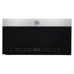
Microwave Oven
INSTRUCTION MANUAL
Model: KOTR24XV
Read these instructions carefully before using your microwave oven and keep it carefully.
If you follow the instructions, your oven will provide you with many years of good service.
SAVE THESE INSTRUCTIONS CAREFULLY
PRECAUTIONS TO AVOID POSSIBLE EXPOSURE TO EXCESSIVE MICROWAVE
ENERGY
(a) Do not attempt to operate this oven with the door open since open-door operation can result in harmful exposure to microwave
energy.
It is important not to defeat or tamper with the safety interlocks.
(b) Do not place any object between the oven front face and the door or allows soil or cleaner residue to accumulate on sealing
surfaces.
(c) Do not operate the oven if it is damaged. It is particularly important that the oven door close properly and that there is no
damage to the:
(1) DOOR (bent)
(2) HINGES AND LATCHES (broken or loosened)
(3) DOOR SEALS AND SEALING SURFACES
(d) The oven should not be adjusted or repaired by anyone except properly qualified service personnel.
Specifications
Model
KOTR24XV
Rated Voltage
120 VAC, 60 Hz
Microwave Input
1500 W
Microwave Output
1000 W
EN-6

IMPORTANT SAFETY INSTRUCTIONS
When using electrical appliances basic safety precautions should be followed, including the following:
WARNING - To reduce the risk of burns, electric shock, fire, injury to persons or exposure to excessive microwave energy:
1. Read all instructions before using the appliance.
2. Read and follow the specific: “PRECAUTIONS TO AVOID POSSIBLE EXPOSURE TO EXCESSIVE MICROWAVE ENERGY”
found on page 2.
3. This appliance must be grounded. Connect only to properly grounded outlet. See “GROUNDING INSTRUCTIONS” found on
page 4.
4. Install or locate this appliance only in accordance with the provided installation instructions.
5. Some products such as whole eggs and sealed containers - for example, closed glass jars - are able to explode and should not
be heated in this oven.
6. Use this appliance only for its intended use as described in the manual. Do not use corrosive chemicals or vapors in this
appliance. This type of oven is specifically designed to heat, cook or dry food. It is not designed for industrial or laboratory use.
7.
8. Do not operate this appliance if it has a damaged cord or plug, if it is not working properly, or if it has been damaged or
dropped.
9. This appliance should be serviced only by qualified service personnel. Contact nearest authorized service facility for
examination, repair, or adjustment.
10. Do not cover or block any openings on the appliance.
11. Do not store this appliance outdoors. Do not use this product near water - for example, near a kitchen sink, in a wet basement,
near a swimming pool, or similar location.
12. Do not immerse cord or plug in water.
13. Keep cord away from heated surface.
14. Do not let cord hang over edgeof table or counter.
15. When cleaning surfaces of door and oven that comes together on closing the door, use only mild, nonabrasive soaps, or
detergent applied with a sponge or soft cloth.
16. To reduce the risk of fire in the oven cavity:
1). Do not overcook food. Carefully attend appliance when paper, plastic, or other combustible materials are placed inside the
oven to facilitate cooking.
2). Remove wire twist-ties from paper or plastic bag before placing bag in oven.
3). If material inside of the oven ignite, keep oven door closed, turn oven off, and disconnect the power cord, or shut off power
at the fuse or circuit breaker panel.
4). Do not use the cavity for storage purposes. Do not leave paper products, cooking utensils, or food in the cavity when not in
use.
17. Liquids, such as water, coffee, or tea are able to be overheated beyond the boiling point without appearing to be boiling. Visible
bubbling or boiling when the container is removed from the microwave oven is not always present.
EN-7
HOT CONTENTS CAN CAUSE SEVERE BURNS. DO NOT ALLOW
CHILDREN TO USE THE MICROWAVE. Use caution when
removing hot items.

THIS COULD RESULT IN VERY HOT LIQUID SUDDENLY BOILING OVER WHEN THE CONTAINER IS DISTURBED OR A
UTENSIL IS INSERTED INTO THE LIQUID.
To reduce the risk of injury to persons:
1) Do not overheat the liquid.
2) Stir the liquid both before and halfway through heating it.
3) Do not use straight-sided containers with narrow necks.
4) After heating, allow the container to stand in the microwave oven for a short time before removing the container.
5) Use extreme care when inserting a spoon or other utensil into the container.
18. Clean Ventilation Hoods Frequently - Grease should not be allowed to accumulate on hood or filter.
19. When flaming foods under the hood, turn the fan on.
20. Use care when cleaning the vent-hood filter. Corrosive cleaning agents, such as lye-based oven cleaners, may damage the filter.
21. Suitable for use above both gas and electric cooking equipment.
EN-8

SAVE THESE INSTRUCTIONS
GROUNDING INSTRUCTIONS
This appliance must be grounded. In the event of an electrical short circuit, grounding reduces the risk of electric shock by providing
an escape wire for the electric current. This appliance is equipped with a cord having a grounding wire with a grounding plug. The
plug must be plugged into an outlet that is properly installed and grounded.
WARNING - Improper use of the grounding can result in a risk of electric shock.
Consult a qualified electrician or serviceman if the grounding instructions are not completely understood, or if doubt exists as to
whether the appliance is properly grounded. If it is necessary to use an extension cord, use only a 3-wire extension cord that has a
3-blade grounded plug, and 3-slot receptacle that will accept the plug on the appliance. The marked rating of the extension cord
shall be equal to or greater than the electrical rating of the appliance.
DANGER - Electric Shock Hazard
Touching some of the internal components can cause serious personal injury or death. Do not disassemble this appliance.
WARNING - Electric Shock Hazard
Improper use of the grounding can result in electric shock. Do not plug into an outlet until appliance is properly installed and
grounded.
1. A short power-supply cord is provided to reduce the risks resulting from becoming entangled in or tripping over a longer cord.
2. Longer cord sets or extension cords are available and may be used if care is exercised in their use.
3. If a long cord or extension cord is used:
1) The marked electrical rating of the cord set or extension cord should be at least as great as the electrical rating of the
appliance.
2) The extension cord must be a grounding-type 3-wire cord.
3) The longer cord should be arranged so that it will not drape over the counter top or tabletop where it can be pulled on by
children or tripped over unintentionally.
EN-9

UTENSILS
CAUTION - Personal Injury Hazard
Tightly-closed utensils could explode. Closed containers should be opened and plastic pouches should be pierced before cooking.
See the instructions on “Materials you can use in microwave oven or to be avoided in microwave oven.”
There may be certain non-metallic utensils that are not safe to use for microwaving. If in doubt, you can test the utensil in question
following the procedure below.
Utensil Test:
1. Fill a microwave-safe container with 1 cup of cold water (250ml) along with the utensil in question.
2. Cook on maximum power for 1 minute.
3. Carefully feel the utensil. If the empty utensil is warm, do not use it for microwave cooking.
4. Do not exceed 1 minute cooking time.
EN-10
This product has been tested and found to comply with the limits or Microwave Oven, pursuant to Part 18 of the FCC
Rules.
This product can radiate radio frequency energy,
which could cause interference to such products as radio, TV, baby monitor,
cordless
phone,
Bluetooth,
wireless
router,
etc., which can be confirmed by turning this product off and
on. If present, the
user is encouraged to try to correct by
taking one or more of the following countermeasures:
(1) Increase the spacing distance between the microwave
oven and other product receiving the interference.
(2) If possible, use a properly installed receiver antenna
and/or reorient the receiving antenna of the other
product receiving the interference.
(3) Plug the microwave oven into a different outl
other product receiving the interference.
(4)
Clean door and sealing surfaces of the oven. (See
Care and Cleaning of Your Microwave Oven)
et from the
RADIO INTERFERENCE

Materials you can use in microwave oven
Utensils
Remarks
Browning dish
Follow manufacturer* instructions. The bottom of browning dish must be
at least 3/16 inch (5mm) above the turntable. Incorrect usage may cause
the turntable to break.
Dinnerware
Microwave-safe only. Follow manufacturer's instructions. Do not use
cracked or chipped dishes.
Glass jars
Always remove lid. Use only to heat food until just warm. Most glass jars
are not heat resistant and may break.
Glassware
Heat-resistant oven glassware only. Make sure there is no metallic trim.
Do not use cracked or chipped dishes.
Oven cooking
bags
Follow manufacturer* instructions. Do not close with metal tie. Make slits
to allow steam to escape.
Paper plates
and cups
Use for short*erm cooking/warming only. Do not leave oven unattended
while cooking.
Paper towels
Use to cover food for reheating and absorbing fat. Use with supervision
for a short-term cooking only.
Parchment
paper
Use as a cover to prevent splattering or a wrap for steaming.
Materials you can use in microwave oven
Utensils
Remarks
Plastic
Microwave-safe only. Follow the manufacturer* instructions. Should be
labeled “Microwave Safe”. Some plastic containers soften, as the food
inside gets hot. “Boiling bags” and tightly closed plastic bags should be
slit, pierced or vented as directed by package.
Plastic wrap
Microwave-safe only. Use to cover food during cooking to retain
moisture. Do not allow plastic wrap to touch food.
Thermometers
Microwave-safe only (meat and candy thermometers).
Wax paper
Use as a cover to prevent splattering and retain moisture.
EN-11

Materials you can use in microwave oven
Utensils
Remarks
Aluminum tray
May cause arcing. Transfer food into microwave-safe dish.
Food carton with
metal handle
May cause arcing. Transfer food into microwave-safe dish.
Metal or metal
trimmed utensils
Metal shields the food from microwave energy. Metal trim may cause
arcing.
Metal twist ties
May cause arcing and could cause a fire in the oven.
Paper bags
May cause a fire in the oven.
Plastic foam
Plastic foam may melt or contaminate the liquid inside when exposed to
high temperature.
Wood
Wood will dry out when used in the microwave oven and may split or
crack.
EN-12
EN-13
OPERATING INSTRUCTION
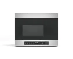
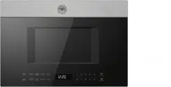
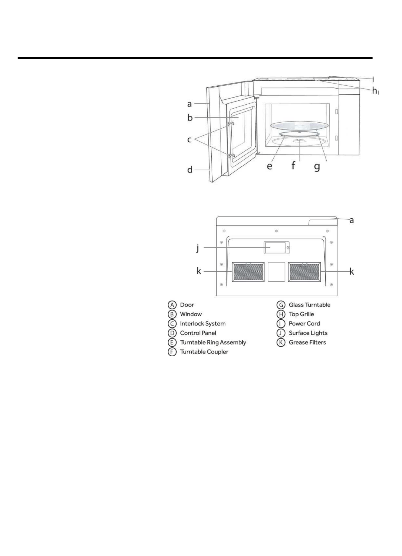
FEATURES OF YOUR MICROWAVE
Front view
Bottom view
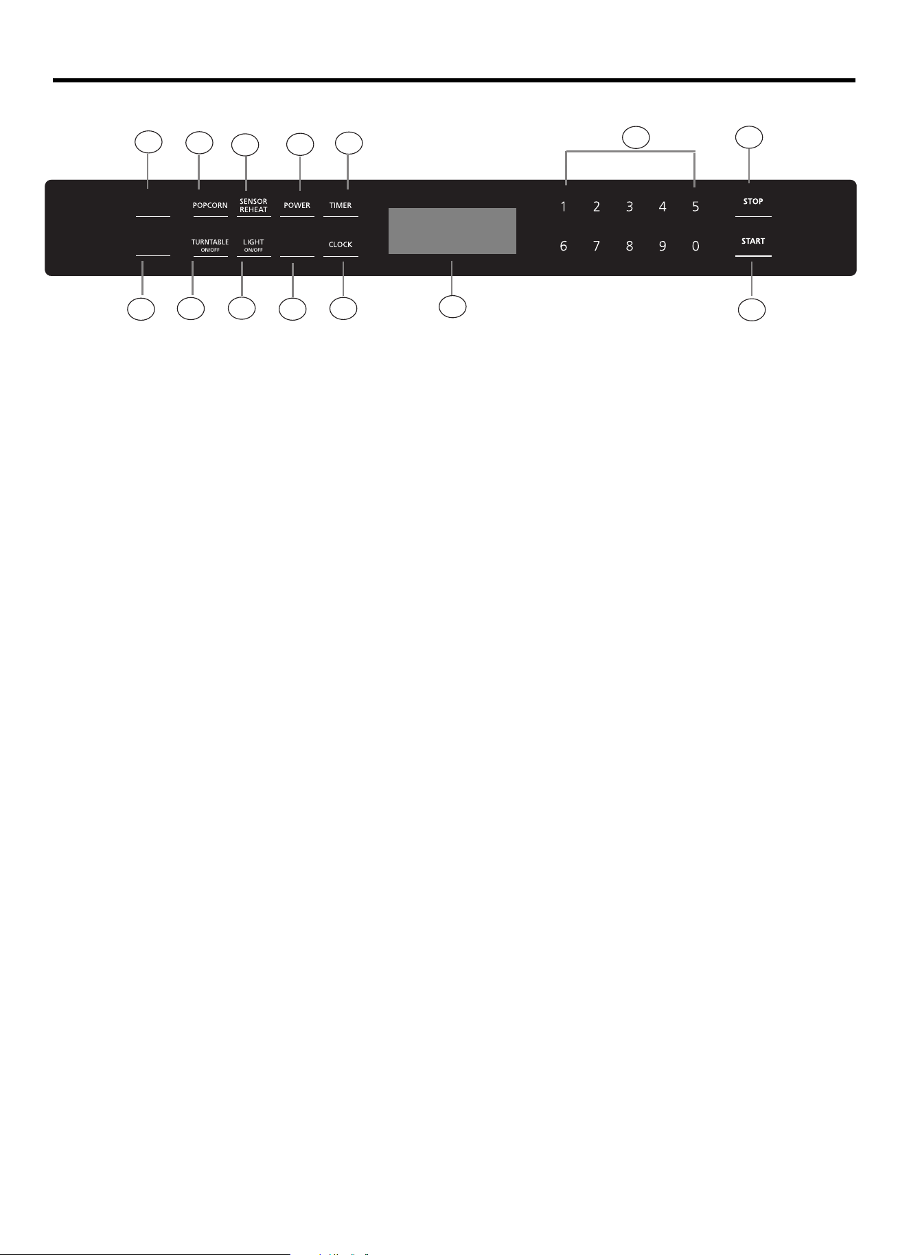
CONTROLS
EN-14
1) Sensor Cook
2) Popcorn
3) Sensor Reheat
4) Power
6) Auto Defrost
7) Turntable ON/OFF
8) Light O /
11) Number Pads
12) Stop/Reset
13) Start/ 30Sec.
5) Timer
14) Dispplay Screen
9) Vent Speed
10) Clock
+
OFFN
1
3
4
8
7
10
2
6
5
14
13
12
11
9
AUTO
DEFROST
SENSOR
COOK
VENT SPEED
RESET
+30 SEC

Operation
1. Power
11 power levels are available.
Level
10
9
8
7
6
5
4
3
2
1
0
Power
100%
90%
80%
70%
60%
50%
40%
30%
20%
10%
0%
Display
PL-HI
PL-90
PL-80
PL-70
PL-60
PL-50
PL-40
PL-30
PL-20
PL-10
PL-0
2. Power On
When the microwave oven is electrified, the screen will display “12:00 “PRESS CLOCK ENTERTIME”. The buzzer will ring once. Press
number keys to set clock or press “
STOP/RESET” to exit clock setting mode. If there is no operation within 5minutes, the oven will enter
waiting state.
3. Clock
The clock can be set in 12-hour mode.
1) In waiting state, press “Clock” once. the screen will display “12:00 PRESS CLOCK ENTER TIME”.
2) Press the number keys and enter the correct time. For example, time is 10:12 now, please press “1,0,1, 2” in turn.
3) Press “Start/+30 Sec” button to confirm the clock.
EN-15
"
counting down.
once,
" ENTER TIME " will blink in the display.
1) Press "
Timer
2) Press the number keys and enter the timer time.(The maxumum value is 99:99).
3) Press "
" to confirm setting.The kitchen time will start
Start/+30 Sec
4 . Kitchen Timer

6. Lock-out Function for Children
You can use this function to prevent children from accidentally turning the oven on.
To activate the lock:
In waiting state, press and hold “STOP/RESET” for three seconds. A long beep sounds and the locked icon will display.
To deactivate the lock:
In locked state, press and hold “STOP/RESET” for three seconds. A long beep sounds.
7. Speed y Cooking
(1) In waiting state, instant cooking at 100% power level can be started by select a cooking time from 1 to 9 minutes by pressing
number pads1 to 9.
(2) In waiting state, instant cooking at 100% power level with 30 seconds' cooking time can be started by pressing “
Start/+30
Sec
”. Each press on the same button will increase cooking time by 30 seconds. The maximum cooking time is 99 minutes and
99 seconds.
EN-16
2) Press "
1)In waiting state,press the number keys to set the cooking time.(The maximum value is 99:99).
" repeatedly to adjust the power level. The default power is PL-HI.
3) Press "
" to start microwave cooking.
Power
Start/+30 Sec
5 . Time Cook

8. Popcorn
1) Press “Popcorn” repeatedly until the number you wish appears in the display.
“1”SET: approximate 3.2 ounces
“2”SET: approximate 1.75 ounces
For example, press “
Popcorn” once, “3.2” appears in the screen.
2) Press “START/+30SEC” to cook.
9. Auto Defrost
1) Press “ ” once, the screen will display “MEAT”.Auto Defrost
2) Press “ ” repeatedly to choose the desired function. And “MEAT”, “POULTRY”, “FISH” or “BREAD” will display in turn.
Auto Defrost
3) Press “
START/+30SEC” to confirm the function. The screen will display “ENTER WEIGHT”.
4) Press the number keys to set the weight of the food.
5) Press “
START/+30SEC” to start defrosting.
Auto Defrost programs
Press button
Food
Weight range
1
Meat
0.1 - 6.0 lbs
2
Poultry
0.1 - 6.0 lbs
3
Fish
0.1 - 6.0 lbs
4
Bread
0.1 - 6.0 lbs
10. Sensor Reheat
EN-17
Sensor Reheat programs
" repeatedly until the menu you wish appears in the display.
"
Sensor Reheat
1) Press "
2) Press "
5) Press " " to start sensor cook mode. The appliance starts sensing.
3) Press " " to confirm.
4) Press the number key “1-3” to
set the weight of the food. (For the menus “Dinner Plate,
Pizza, Casserole”, please skip this step.)
The microwave is operating during sensing. When sensing is complete, beeps will
sound and the calculated cook time will start to count down.
Note: Do not open the door during the sensing process, or the program will be cancelled.
once , the screen will dis p lay "BEVERAGE".
START/+30SEC
START/+30SEC
Sensor Reheat
1 - 3 cups
Quantity
1
2
3
4
5
Menu
1 plate
1-3 cups
10.5 oz
Program
no.
Beverage
Dinner Plate
Soup/Sauce
Casserole
Pizza
1 - 4 slices

11. Sensor Cook
1) Press “Sensor Cook once, the screen will display “POTATO”. ”
2)
Press “Sensor Cook repeatedly until the menu you wish appears in the display. ”
3) Press “START/+30SEC” to start sensor cook mode. The appliance starts sensing. The microwave is operating during sensing. When
sensing is complete, beeps will sound and the calculated cook time will start to count down.
Note: Do not open the door during the sensing process, or the program will be cancelled.
Sensor Cook programs
Program no.
Menu
Quantity
1
Potato
1 - 4 potatoes
2
Fresh Vegetable
6/16 oz
3
Frozen Vegetable
8/16 oz
4
Frozen Dinner
10/20 oz
5
Rice
1 - 2 cups
6
Frozen Breakfast
8 - 12 oz
7
Meat
9-19 oz
12. Multi-Stage Cooking
Notes: (1) Two cooking stages can be set in multi-stage cooking.
(2) If you set defrost function, it will work automatically in the first stage.
Example: Defrost the Poultry for 2.0 lbs and then cook with 80% microwave power for 5 minutes.
(1) In waiting state, press number keys to set the microwave cooking time to 5 minutes.
(2) Press “
Power ” repeatedly to set the power level of PL-80.
(3) Press “ “ twice and then the screen will display “
Poultry “.
(4) Press “
START/+30SEC “ to confirm the menu.
(5) Press number keys to set the weight for 2.0 lbs.
(6) Press “
START/+30SEC “ to start cooking.
13. Operating the Ventilation Fan
EN-18
1) Press " " once to start ventilation fan, the screen will display "HIGH" .
Vent
The oven will return to waiting state after 2 seconds.
" twice, the screen will display "LOW" .
Vent Speed
The oven will return to waiting state after 2 seconds.
" thrice , the screen will
Vent
The oven will return to waiting state after 2 seconds.
2) Press "
3) Press " to turn off the ventilation fan
display "OFF" .
Auto Defrost
Speed
Speed

14. Turning the Light on/off
The appliance is equipped with a cooking surface light, to light the surface underneath the appliance. With the “Light
On/Off” button you can set two brightness levels.
Display
Brightness
HI
High
LO
Low
OFF
Off
15. Turning the turntable on / off
For best cooking results, leave the turntable on. It can be turned off for large dishes. To turn the turntable off, press
“Turntable On/Off “ once.
The screen will display “OFF” for 2 seconds. Press “Turntable On/Off”again to turn the turntable on. The screen will
display “ON” for 2 seconds.
EN-19
MAINTENANCE
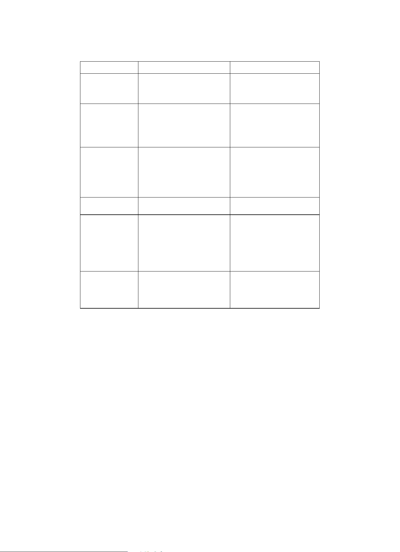
Troubleshooting
Check your problem by using the chart below and try the solutions for each problem. If the microwave oven still does not work properly,
contact the nearest authorized service center.
TROUBLE
POSSIBLE CAUSE
POSSIBLE REMEDY
Oven will not start
a. Electrical cord for oven is not
plugged in.
b. Door is open.
c. Wrong operation is set.
a. Plug into the outlet.
b. Close the door and try again.
c. Check instructions.
Arcing or sparking
a. Materials to be avoided in
microwave oven were used.
b. The oven is operated when
empty.
c. Spilled food remains in the
cavity.
a. Use microwave-safe cookware
only.
b. Do not operate with oven
empty.
c. Clean cavity with wet towel.
Unevenly cooked
foods
a. Materials to be avoided in
microwave oven were used.
b. Food is not defrosted
completely.
c. Cooking time, power level is not
suitable.
d. Food is not turned or stirred.
a. Use microwave-safe cookware
only.
b. Completely defrost food.
c. Use correct cooking time,
power level.
d. Turn or stir food.
Overcooked foods
Cooking time, power level is not
suitable.
Use correct cooking time, power
level.
Undercooked foods
a. Materials to be avoided in
microwave oven were used.
b. Food is not defrosted
completely.
c. Oven ventilation ports are
restricted.
d. Cooking time, power level is not
suitable.
a. Use microwave-safe cookware
only.
b. Completely defrost food.
c. Check to see that oven venti-
lation ports are not restricted.
d. Use correct cooking time,
power level.
Improper defrosting
a. Materials to be avoided in
microwave oven were used.
b. Cooking time, power level is not
suitable.
c. Food is not turned or stirred.
a. Use microwave-safe cookware
only.
b. Use correct cooking time,
power level.
c. Turn or stir food.
EN-20

Installation
Instructions
Over the Range
Microwave Oven
BEFORE YOU BEGIN
Read these instructions completely and carefully.
• IMPORTANT — Save these instructions
for local inspector’s use.
• IMPORTANT — Observe all governing
codes and ordinances.
• Note to Installer — Be sure to leave these instructions
with the Consumer.
Note to Consumer —
Keep these instructions for future
reference.
Skill level - Installation of this appliance requires basic mechanical
and electrical skills.
Proper installation is the responsibility of the installer.
Product failure due to improper installation is not covered
under the Warranty.
READ CAREFULLY.
KEEP THESE INSTRUCTIONS.
Installation Instruction
EN-22
CONTENTS
General information
Important Safety Instructions ............................................. 23
Electrical Requirements ...................................................... 23
Damage - Shipment/Installation........................................... 24
Parts Included ....................................................................... 24
Tools You Will Need ............................................................ 25
Mounting Space .................................................................... 25
Step-by-step installation guide
Placement of The Mounting Plate .................................. 26-28
Removing the Mounting Plate ...................................... 26
Finding the Wall Studs .................................................. 26
Determining Wall Plate Location ................................. 27
Aligning the Wall Plate ................................................ 28
Installation Types ............................................................. 29-42
Hood Exhaust ................................................................... 30-31
A Outside Top Exhaust .............................................. 32-35
Attach Mounting Plate to Wall ............................... 32
Preparation of Top Cabinet .................................... 32
Adapting Microwave Blower for
Outside top Exhaust ........................................ 33-34
Checking for Proper Damper Operation .............. 34
Mount the Microwave Oven .......................... 34-35
Adjust the Exhaust Adaptor ................................ 35
Connecting Ductwork .......................................... 35
B Outside Back Exhaust .............................................. 36-39
Preparing Rear Wall for Outside Back Exhaust ... 36
Remove Blower Plate .......................................... 36
Attach Mounting Plate to Wall ........................... 37
Preparation of Top Cabinet ................................. 37
Adapting Microwave Blower
for Outside Back Exhaust ................................ 37-38
Mount the Microwave Oven ................................. 39
C Recirculating ............................................................ 40-42
Attach Mounting Plate to Wall .............................. 32
Preparation of Top Cabinet .................................... 33
Check Blower Plate .............................................. 41
Mount the Microwave Oven ........................... 41-42
Installing or Change the Charcoal Filter ............... 42
Before You Use Your Microwave ........................................ 44
Template Information ........................................................... 46
Installation Instruction
EN-23
IMPORTANT SAFETY INSTRUCTIONS
This product requires a three-prong grounded outlet. The
installer must perform a ground continuity check on the power
outlet box before beginning the installation to ensure that the
outlet box is properly grounded. If not properly grounded, or if
the outlet box does not meet electrical requirements noted
(under ELECTRICAL REQUIREMENTS), a qualified
electrician should be employed to correct any deficiencies.
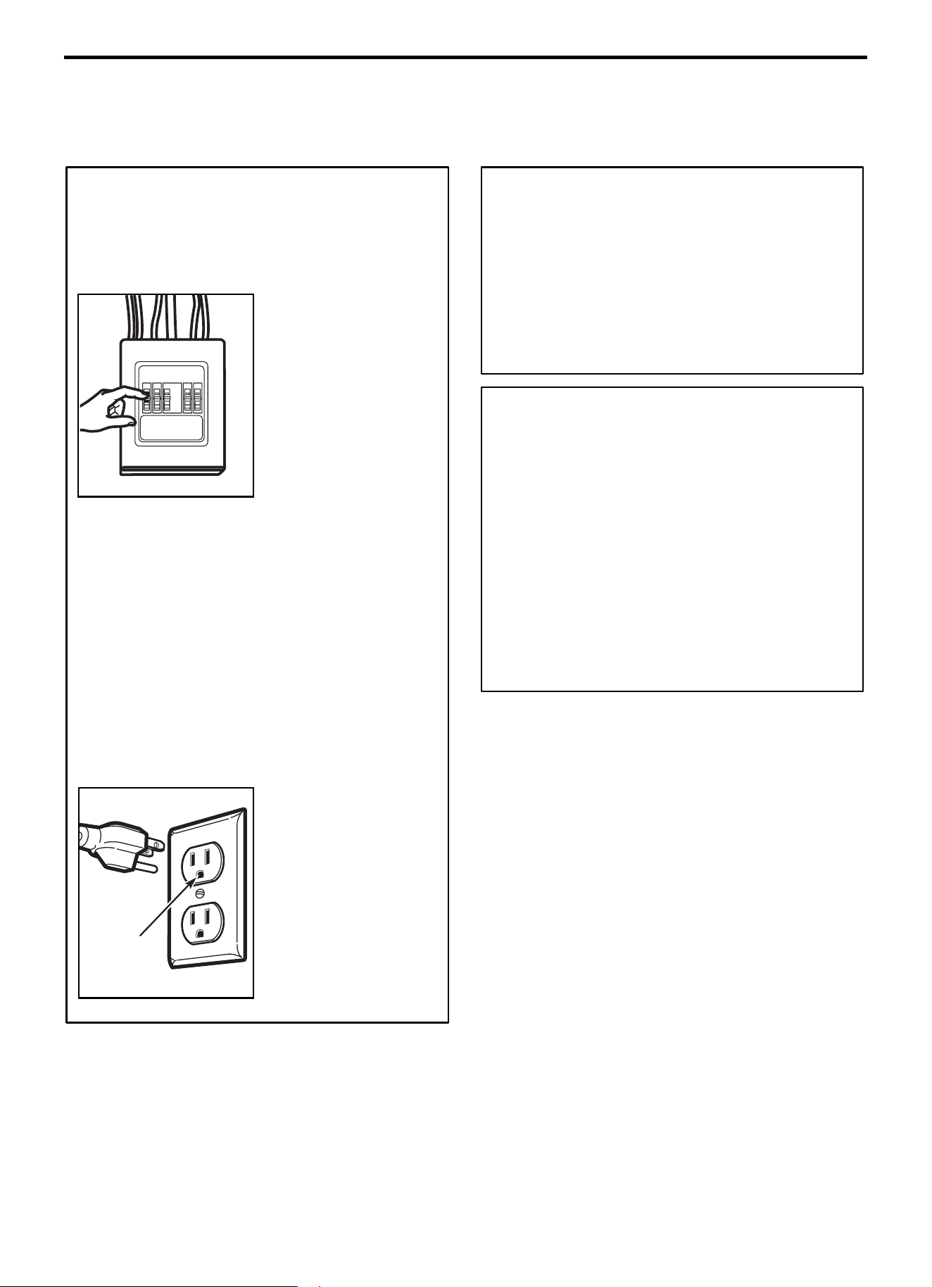
CAUTION: For personal
safety, remove house fuse
or open circuit breaker
before beginning
installation to avoid severe
or fatal shock injury.
CAUTION: For personal safety, the mounting surface
must be capable of supporting the cabinet load, in addition
to the added weight of this 63-85 pound (28.5-38.5 kg)
product, plus additional oven loads of up to 50 pounds
(22.7 kg) or a total weight of 113-135 pounds (51.3-61.2 kg).
CAUTION: For personal safety, this product cannot be
installed in cabinet arrangements such as an island or a
peninsula. It must be mounted to BOTH a top cabinet AND
a wall.
NOTE: For easier installation and personal safety, it is
recommended that two people install this product.
IMPORTANT - PLEASE READ CAREFULLY. FOR
PERSONAL SAFETY, THIS APPLIANCE MUST BE
PROPERLY GROUNDED TO AVOID SEVERE OR
FATAL SHOCK.
The power cord of this
appliance is equipped with
a three-prong (grounding)
plug which mates with a
standard three-prong
(grounding) wall receptacle
to minimize the possibility
of electric shock hazard
from this appliance.
Ensure proper
ground exists
before use
You should have the wall receptacle and circuit checked by
a qualified electrician to make sure the receptacle is
properly grounded.
Where a standard two-prong wall receptacle is
encountered, it is very important to have it replaced with a
properly grounded three-prong wall receptacle, installed
by a qualified electrician.
DO NOT, UNDER ANY CIRCUMSTANCES, CUT,
DEFORM OR REMOVE ANY OF THE PRONGS FROM
THE POWER CORD. DO NOT USE WITH AN
EXTENSION CORD.
ELECTRICAL
REQUIREMENTS
Product rating is 120 VAC, 60 Hz, 15 amps and 1.6
kilowatts. This product must be connected to a seperate and
dedicated supply circuit of the proper voltage and frequency.
Wire size must conform to the requirements of the National
Electrical Code or the prevailing local code for this kilowatt
rating.
The power supply cord and plug should be brought to a
seperate and dedicated 15- to 20- ampere branch circuit single
grounded outlet. The outlet box should be located in the
cabinet above the microwave oven. The outler box and supply
circuit should be installed by a qualifed electrician and
conform to the National Electrical Code or the prevailing local
code.
Installation Instruction
EN-24
DAMAGE—SHIPMENT/
INSTALLATION
• If the unit is damaged in shipment, return the unit to the
store in which it was bought for repair or replacement.
• If the unit is damaged by the customer, repair or
replacement is the responsibility of the customer.
• If the unit is damaged by the installer (if other than the
customer), repair or replacement must be made by
arrangement between customer and installer.
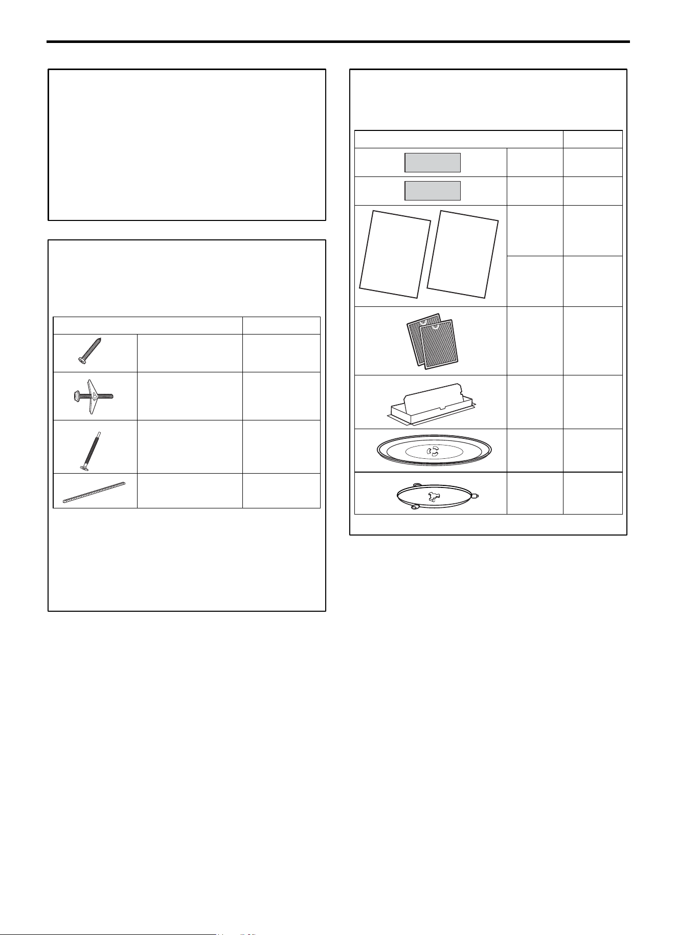
PARTS INCLUDED
HARDWARE PACKET
PART
QUANTITY
Wood Screws
(1/4” x 2”)
2
Toggle Bolts (and wing
nuts) (3/16” x 3”)
2
Self-Aligning Machine
Screws (1/4”-28 x 31/4”)
3
Nylon Grommet (for
metal cabinets)
1
You will find the installation hardware contained in a packet
with the unit. Check to make sure you have all these parts.
NOTE: Some extra parts are included.
PARTS INCLUDED
(CONT.)
ADDITIONAL PARTS
PART
QUANTITY
Top Cabinet
Template
1
Rear Wall
Template
1
Installation
Instructions
1
Use & Care
Manual
1
Separately
Packed
Grease
Filters
2
Exhaust
adaptor
1
Glass Tray 1
Turntable
Ring
1
INSTALLATION
INSTRUCTIONS
USE & CARE
MANUAL
Installation Instruction
EN-25
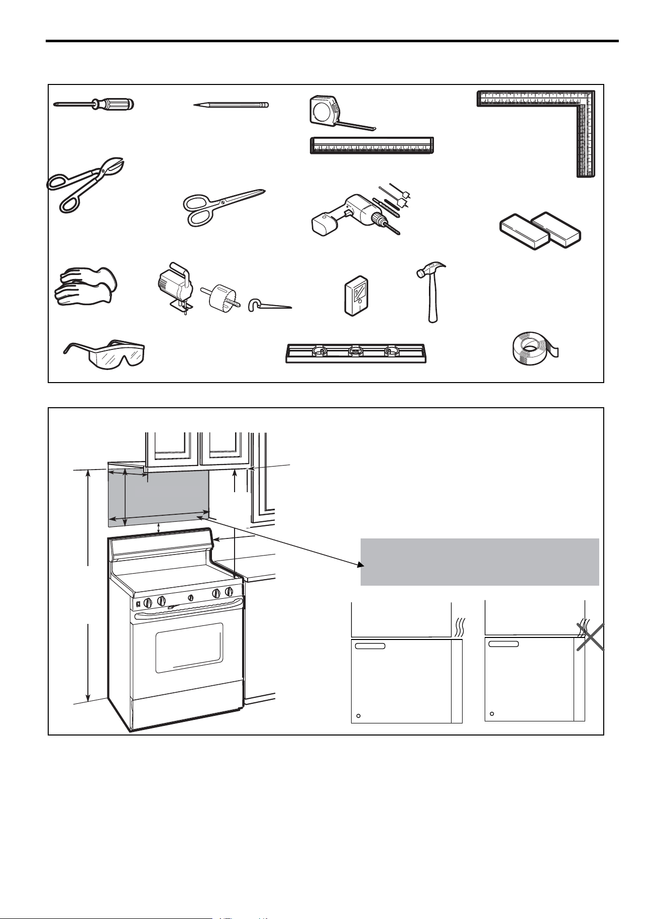
TOOLS YOU WILL NEED
# 1 Phillips screwdriver
Pencil
Tin snips (for cutting damper, if
required)
Scissors
(to cut template, if necessary)
Electric drill with 3/16” and 5/8”
drill bits
Filler blocks or scrap wood
pieces, if needed for top cabinet
spacing (used on recessed
bottom cabinet installations only)
Gloves
Saw (saber, hole or keyhole)
Stud finder or Hammer (optional)
Safety goggles
Level
Duct and masking tape
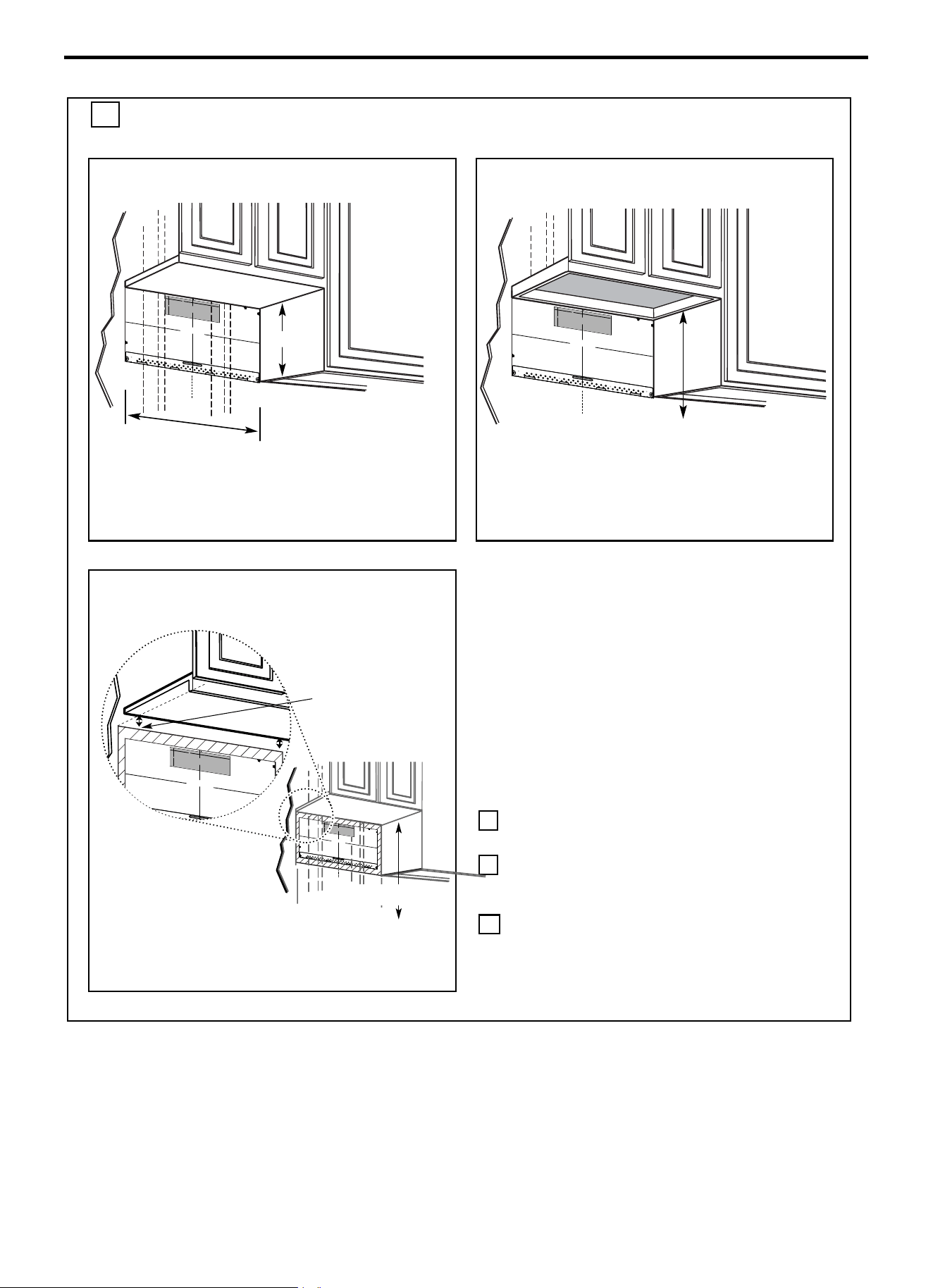
MOUNTING SPACE
NOTES:
• The space between the cabinets must be 24” (61.0
cm)wide and free of obstructions.
• If you are going to vent your microwave oven to the
outside, see Hood Exhaust Section for exhaust duct
preparation.
• When installing the microwave oven beneath smooth,
flat cabinets, be careful to follow the instructions on
the top cabinet template for power cord clearance.
• As a guide to installation, see page 24 for Mounting
Template Information.
• If the cabinet depth including the cabinet doors is more
than 13'' then the unit must be spaced out from wall
using adequate materials supporting 150 Ibs to allow
proper top vent air exhaust/intake.
Cabinet
Cabinet
Ruler or tape measure
and
straight edge
Carpenter square
(optional)
Bottom Edge of
Cabinet Needs to be
30"
" (76.2 cm) or
More from the
Cooking Surface
Backsplash
2
“ (5.1 cm)
30
“
(76.2 cm)
min.
16
1
⁄
2
“
(41.9 cm)
24“
(61.0cm)
13" Maximum (33 cm)
66" (167.6 cm)
or More from
the Floor to the
Top of the
Microwave
Installation Instruction
EN-26
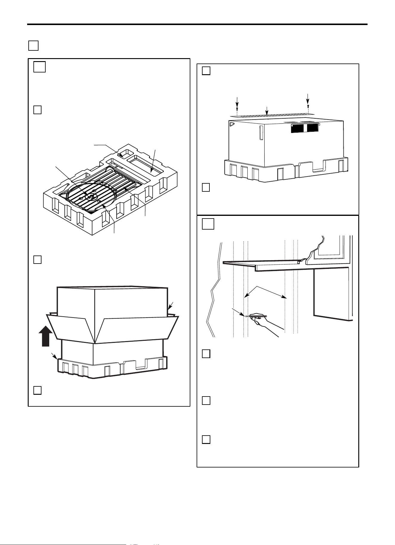
1 PLACEMENT OF THE MOUNTING PLATE
Cabinet
A. REMOVING THE MICROWAVE
OVEN FROM THE CARTON/
REMOVING THE MOUNTING
PLATE
1 Remove the installation instructions, use and care, exhaust
adapter, turntable ring, shelf, filters, glass tray and the
small hardware bag. Do not remove the Styrofoam
protecting the front of the oven.
2 Fold back all 4 carton flaps fully against carton sides.
Then carefully roll the oven and carton over onto the top
side. The oven should be resting in the Styrofoam.
3 Pull the carton up and off the oven.
Small Hardware Bag
Exhaust Adapter
Filters and Turntable
Ring below glass tray
Glass tray
Shelf
(For some models)
Carton
Styrofoam
4 Cut the middle of the outer protective plastic bag to
remove the mounting plate.
5 Remove the screws from each end of the mounting plate.
This plate will be used as the rear wall template and for
mounting. Reinstall the screws into the holes where they
were removed.
Screws
Screws
Mounting Plate
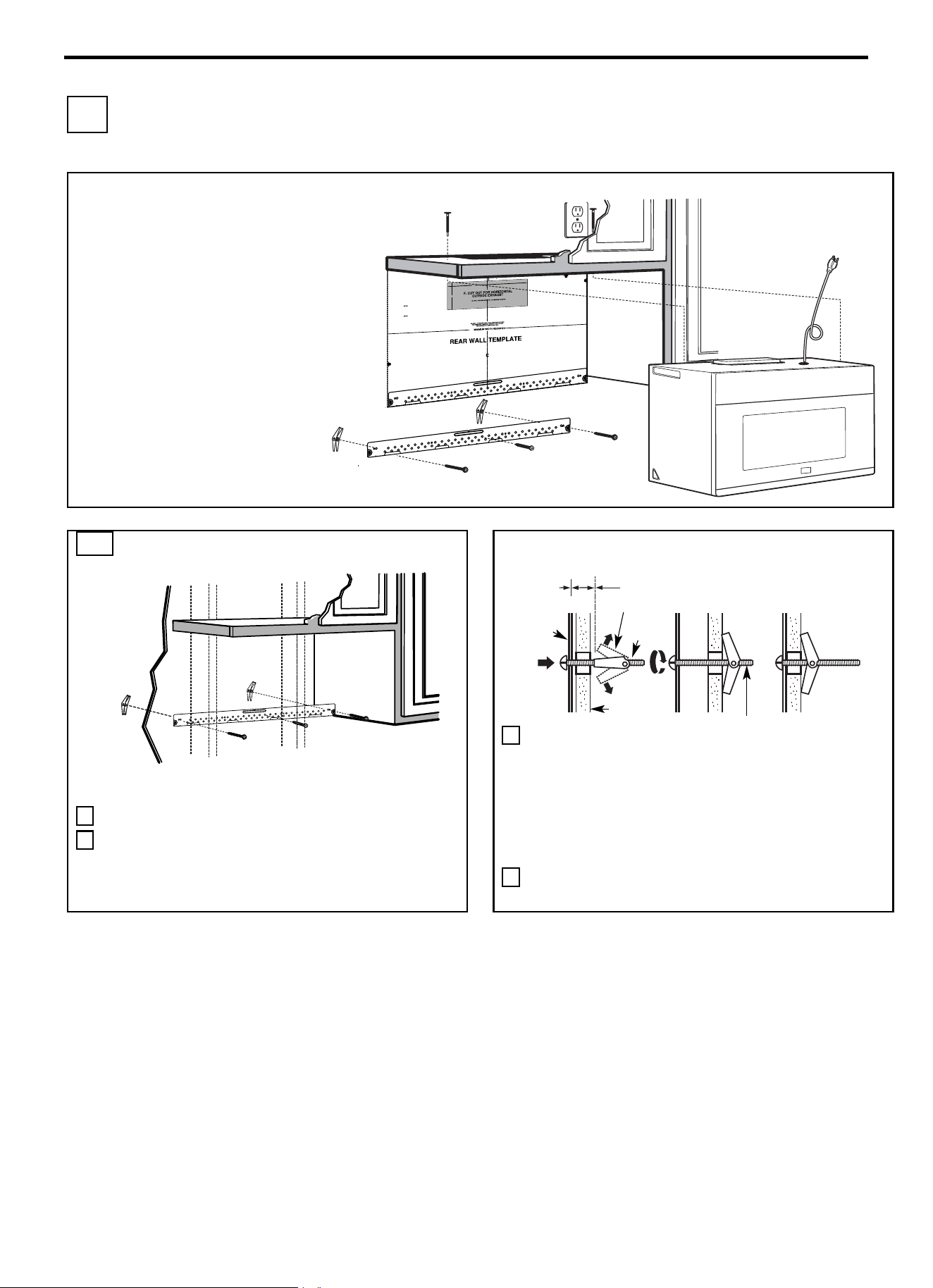
B. FINDING THE WALL STUDS
1 Find the studs, using one of the following methods:
A. Stud finder - a magnetic device which locates
nails.
B. Use a hammer to tap lightly across the mounting
surface to find a solid sound. This will indicate a
stud location.
2 After locating the stud(s), find the center by probing
the wall with a small nail to find the edges of the
stud. Then place a mark halfway between the edges.
The center of any adjacent studs should be 16" (40.6
cm) or 24" (61 cm) from this mark.
3 Draw a line down the center of the studs.
THE MICROWAVE MUST BE CONNECTED TO AT LEAST ONE WALL
STUD.
Center
Wall
Studs
Installation Instruction
EN-27
C. DETERMINING WALL PLATE LOCATION UNDER YOUR CABINET
Plate position-beneath flat bottom
cabinet
Draw a vertical line on the wall at the center of the
24" wide space.
Tape the Rear Wall Template onto the wall
matching the centerline and touching the bottom of
the cabinet.
Plate position-beneath framed
recessed cabinet bottom
Draw a vertical line on the wall at the center of the
24"space.
Tape the Rear Wall Template onto the wall
matching the centerline and touching the bottom
cabinet frame.
Plate position-beneath recessed bottom
cabinet with front overhang
Draw a line on the back wall equal to the depth of
the front overhang.
Your cabinets may have decorative trim that
interferes with the microwave installation. Remove
the decorative trim to install the microwave
properly and to make it level.
THE MICROWAVE MUST BE LEVEL.
Use a level to make sure the cabinet bottom is
level.
If the cabinets have a front overhang only, with no
back or side frame, install the mounting plate
down the same distance as the front overhang
depth. This will keep the microwave level.
1
Measure the inside depth of the front
overhang.
2 Draw a horizontal line on the back wall an
equal distance below the cabinet bottom as
the inside depth of the front overhang.
3 For this type of installation with front overhang
only, align the mounting tabs with this
horizontal line, not touching the cabinet
bottom as described in Step D.
At least 24
30" to Cooktop
²
C
3/8" T
O
ED
G
E
N
O
T
E: I
T
IS VER
Y IMPORTANT TO
R
EAD
AND
FOLLOW
THE DIREC
T
IONS
I
N T
HE
I
N
STALL
ATION
INSTRU
C
TION
S
BEF
ORE PROC
EED
I
N
G
W
ITH
TH
IS
R
E
AR
WALL TEM
PLAT
E.
Th
is
Rea
r W
a
l
l T
e
mp
l
a
t
e
se
rve
s to p
ositio
n the bo
tto
m
mo
u
ntin
g
pla
te
and
to lo
ca
te th
e
h
o
rizontal exh
a
u
st
o
u
tlet
.
1. Use
a
le
ve
l to ch
e
ck t
h
a
t the te
mplate
is
p
o
si
tio
ned
a
ccu
rately.
2
.
Loca
te and
ma
rk at least o
n
e stu
d o
n th
e
le
ft o
r
righ
t sid
e
o
f t
h
e cen
ter
line.
It is imp
o
rta
n
t
to use at
lea
st o
n
e wo
o
d
scre
w
mo
u
n
te
d
firmly in
a
stu
d to suppo
rt t
h
e we
ig
ht
o
f
t
he microw
ave. Ma
rk two
a
d
diti
o
nal, evenly
sp
aced
loca
tio
n
s
for t
h
e
supp
l
ied
tog
g
le
bolts.
3
.
D
rill
hole
s
in th
e
m
a
r
ke
d
lo
ca
tio
n
s.
W
here the
re
is
a stud, drill a 3/16" h
ol
e f
o
r wo
o
d screw
s.
Fo
r h
o
le
s
t
h
at do n
o
t lin
e
u
p
with
a
stu
d
,
dr
ill 5/
8" ho
l
e
s fo
r
to
gg
l
e bolt
s.
DO NOT
I
NST
A
L
L THE MOU
NT
IN
G P
LA
TE
AT T
H
IS
T
IME.
4
.
Remo
ve
the temp
la
te
from the
re
a
r wall.
5.
Re
vie
w t
he I
nsta
llatio
n
In
stru
cti
on
book fo
r
you
r
i
n
sta
llation
situation.
Lo
cate and m
ar
k
h
oles
t
o
ali
gn
w
ith
ho
les
in the
m
o
unt
ing
plate
.
I
M
P
O
R
T
ANT:
LOC
AT
E
A
T
LEAST
ON
E ST
UD ON
E
IT
HER
SIDE OF
TH
E
CE
N
T
ER
LI
NE.
M
A
R
K
TH
E
LOCAT
ION
F
OR
2 A
D
D
I
TIO
N
AL, EVENL
Y
SPA
C
ED TOGGL
E BOLT
S IN THE
M
OU
N
TI
NG PLAT
E
AREA.
Loc
at
e
a
nd
mark holes
to
align
with holes
in
t
he
mou
nt
i
ng
plat
e
.
I
MPOR
TANT:
LOCATE AT LEAST
ON
E S
TU
D
ON
E
ITH
ER
SI
D
E OF
THE
CENTE
R
LIN
E
.
MAR
K
TH
E LOC
ATI
ON F
OR
2
A
DDI
TI
ON
AL,
E
VENLY
SPA
C
ED
TOGGLE
BOLTS
IN THE MOUNTIN
G
P
LATE
AREA.
T
rim the re
ar
wall
te
m
pl
ate
al
on
g
th
e
dotted
li
n
e.
T
rim the
rear
wal
l
tem
pl
at
e al
ong
th
e
d
o
tte
d
li
ne.
12"
4
"
Da
r
le
v
ue
lta
a
la
hoja
para
c
ons
ultar
la
v
ers
ión
e
n
Esp
a
ñ
ol.
2″
16-1/2
24"
C
3/
8
"
TO
E
D
GE
NOTE:
I
T
IS
VERY
IMPO
RT
ANT TO
RE
A
D
A
ND FO
LLOW
T
HE DIRECT
IO
NS
IN THE INSTALLA
TION
I
NS
TRUCT
I
ONS
BE
F
OR
E PR
OCE
EDING
WI
T
H
T
HIS
RE
AR WA
LL T
E
MP
LATE
.
Th
i
s
R
ea
r
Wa
l
l
Temp
l
a
te
ser
ves to
p
o
si
t
ion the
b
ot
tom
mo
un
t
in
g p
late
a
n
d t
o
locate
t
h
e
h
o
r
i
z
on
tal
e
xhaust
ou
tl
e
t
.
1
.
Use a
le
ve
l
to
che
ck t
hat
the
t
emp
late
i
s
p
osi
ti
on
ed
a
ccur
ate
ly.
2.
L
oc
ate
and
ma
r
k
at least o
n
e stu
d
on
the l
e
ft
or
r
i
gh
t
s
i
de
o
f th
e
c
ent
e
r
lin
e.
It
i
s
imp
orta
nt t
o use
a
t l
e
ast o
ne
wood
sc
r
ew
m
o
u
n
t
ed
fi
rml
y in
a
stu
d t
o su
ppor
t
the we
i
ght
of th
e m
icrow
ave. Mar
k
tw
o a
d
di
tion
al
,
e
ve
nl
y spa
ce
d
l
ocati
o
ns for the
su
ppl
ie
d
tog
gl
e
b
olts.
3. Drill holes in
the
m
ar
ked
l
oca
tio
n
s. Wh
er
e t
here is
a
stu
d,
d
rill a
3/
1
6"
hole for
w
oo
d scr
e
w
s.
For hol
es
th
a
t
do
n
o
t
lin
e
up w
i
t
h
a
st
u
d,
d
ri
ll
5/8
" h
ol
es f
o
r
t
o
g
gle b
ol
ts
.
D
O
NOT
I
N
STALL
THE
MOUNTIN
G PLA
TE
AT TH
IS T
IME.
4.
R
em
o
ve the
te
mp
la
te
fr
o
m t
h
e rear
w
all.
5.
R
evie
w
the
Insta
l
l
a
tio
n
I
nstruction
b
ook f
o
r yo
ur
i
n
sta
ll
at
io
n si
tuation.
Loc
at
e and
mark
hol
es to
ali
gn with
h
oles
i
n
the
mount
i
ng
plate.
I
MPO
RT
ANT:
LOCA
TE AT LEAST ONE
S
TUD
ON
EIT
HER S
IDE
OF
THE
CENT
ER
L
INE
.
MAR
K THE LOC
A
T
IO
N
FO
R
2
AD
DI
T
IONA
L, E
VE
NLY
SP
A
CE
D
TOGGLE
B
OLT
S
I
N TH
E
MOUNTING PLATE
A
R
EA.
Loc
at
e and
ma
rk h
ol
es
t
o a
l
i
gn
with
hol
e
s in the
moun
t
i
ng pl
at
e.
IMPO
RTANT
:
LOCA
T
E
AT LE
A
ST ONE
S
TUD
ON
EITHE
R
S
IDE
OF
THE CE
NT
ERL
I
NE.
MA
RK T
HE
LOC
AT
ION
FO
R
2
ADDI
T
IONA
L, E
V
ENL
Y
S
PA
CED T
O
GGLE
B
OLTS IN THE
MOUNT
ING PL
A
T
E
A
REA.
Trim
the
rear
wa
ll templ
ate
al
on
g the
dott
e
d lin
e.
T
rim
th
e
rear w
all temp
l
ate
al
ong t
he
do
tt
ed
lin
e.
12"
4"
Darle v
uelt
a
a
la
ho
ja
para
co
n
s
ult
a
r
la
v
ersió
n
en
E
s
p
a
ñ
o
l.
24"
C
3/
8"
TO
E
DGE
N
OTE:
IT IS
VERY
IMP
O
R
T
A
NT T
O
R
E
AD
A
N
D
FO
LL
O
W
T
H
E
D
IR
E
C
T
ION
S
IN
T
H
E
IN
S
T
A
L
L
ATION
INST
R
UC
T
IO
N
S
B
E
F
OR
E P
R
OCEE
DING WIT
H
T
H
IS
RE
A
R
W
A
LL
T
E
MP
L
A
TE.
This
Re
a
r W
all
Te
mpl
a
t
e
s
er
ve
s
t
o p
o
sit
io
n
t
he
bo
tt
o
m
m
o
u
nti
ng
plat
e
a
nd
t
o lo
ca
t
e
t
h
e
ho
ri
zo
nt
al
e
x
h
au
st
o
u
t
let
.
1.
Us
e
a
lev
el
t
o
c
h
ec
k
t
h
a
t
th
e
t
em
plate
is p
o
s
it
io
n
e
d
a
c
c
u
ra
t
e
ly.
2
.
Lo
c
at
e
an
d
m
ar
k
at
lea
s
t
o
n
e s
t
ud
o
n t
h
e
le
f
t
o
r
ri
ght
s
ide
o
f t
h
e
c
e
n
ter
lin
e
.
It
is
impo
rt
a
n
t
t
o
use at
l
e
a
st
o
ne
w
o
o
d
s
c
re
w
mo
u
n
te
d
f
ir
mly
in
a
st
u
d
to
s
u
p
po
r
t
the
w
e
ight
of
th
e
micr
owa
v
e.
M
ark t
w
o ad
d
iti
o
na
l,
e
v
e
nly
s
pa
c
e
d
loc
at
io
n
s
for
th
e
s
u
pp
lied
t
o
gg
le
bo
lt
s
.
3
.
D
rill
h
ole
s
in
the
m
a
rk
e
d
lo
c
a
t
ion
s
.
Whe
re
th
e
re
is
a
s
t
ud,
d
r
ill
a 3
/
1
6
"
hole
fo
r
w
oo
d
s
c
re
w
s
.
F
or
h
ole
s
th
at
do n
ot
li
n
e
u
p
wit
h
a
s
t
ud
,
drill 5/
8
"
hole
s
for
t
o
gg
le
bo
lt
s.
D
O
N
O
T
I
NS
TALL
T
H
E
MO
U
N
T
I
N
G
P
L
A
TE
AT
TH
IS
TIM
E
.
4
.
R
e
m
o
v
e
t
h
e
te
m
p
la
te
f
rom
t
h
e
r
e
ar
w
al
l.
5.
Re
v
i
e
w
t
h
e
I
n
s
t
a
lla
t
io
n
I
n
s
t
r
u
ct
ion
bo
o
k
f
o
r
y
ou
r
insta
lla
t
ion
s
it
u
at
io
n
.
L
o
c
a
te an
d
ma
rk
h
o
l
es
to
a
li
g
n w
it
h
ho
l
e
s
i
n
the
mo
u
n
t
in
g
p
l
a
te.
IMP
O
R
T
ANT
:
LO
CATE
A
T
LEAS
T
ONE
S
TU
D ON E
I
T
H
ER
S
IDE
O
F
T
HE CE
NTE
R
LIN
E.
MA
RK
T
H
E
LOCAT
ION FO
R
2
A
D
D
ITIO
N
A
L, E
V
E
N
LY
S
P
AC
E
D TOGG
LE B
OL
T
S IN
THE M
O
U
N
T
IN
G P
L
AT
E
A
RE
A
.
Locate a
n
d
ma
r
k ho
l
e
s to
a
lign with holes in
t
h
e
mo
unt
i
ng p
l
a
t
e.
IMPO
RTA
N
T:
LOCA
TE
AT
L
E
AST
ONE
S
T
U
D
ON
EITH
E
R SID
E
O
F
T
H
E
C
ENT
E
R
L
IN
E
.
MARK
TH
E LOC
A
TION
F
OR
2 AD
D
I
T
IONAL
,
E
V
E
N
L
Y
S
PAC
E
D
TO
GG
L
E BOLT
S IN
T
H
E MO
U
N
T
IN
G
P
LAT
E
AR
E
A.
T
r
im
th
e rea
r
w
a
l
l
te
m
p
late
alo
ng th
e do
tte
d
lin
e
.
Trim
th
e r
ear
wa
ll
te
m
p
l
a
te
a
lo
n
g
th
e
d
o
tte
d
line
.
1
2"
4
"
D
a
rle
vu
e
lt
a
a
la
h
o
ja
p
a
ra
c
on
s
u
l
t
a
r
la
v
e
r
si
ó
n
e
n
E
sp
a
ño
l.
C
L
3/8
"
TO EDGE
N
O
TE
:
I
T
IS
VER
Y
IMPORTAN
T T
O
READ
AND FO
LLO
W THE D
IREC
TIO
NS
I
N
TH
E
INST
ALL
ATION
INST
R
U
C
TI
O
N
S
BEFO
RE PRO
C
EED
ING
W
ITH TH
I
S
R
EAR WALL
T
EMPL
AT
E.
Th
is
R
e
a
r W
a
ll Templa
t
e serves
to p
os
it
i
o
n
th
e
b
ot
to
m
mo
u
ntin
g
p
la
te
and t
o l
oc
at
e
the h
o
riz
ontal e
xha
us
t
ou
tle
t.
1.
Us
e
a
lev
el to
c
he
ck
th
a
t
th
e templat
e is
po
sitio
n
ed
a
c
curat
ely.
2
.
Loc
ate
and
ma
r
k
a
t le
a
s
t
o
n
e st
u
d
o
n
t
he left
o
r
r
ig
ht s
id
e
o
f
the ce
nte
r
l
ine.
It
is
i
mpo
rta
nt t
o
u
s
e a
t lea
s
t
one
wo
od
s
c
r
e
w
mo
u
nt
ed firmly
in
a
s
tu
d
to
s
upport the
w
e
ig
ht
of
th
e micro
w
a
ve.
Ma
rk
two
a
d
d
itiona
l,
e
v
enl
y
sp
ace
d
lo
ca
tio
ns fo
r th
e
s
uppli
e
d tog
gle
bo
lts.
3.
D
ril
l h
ole
s in
th
e mark
e
d lo
c
atio
n
s
.
W
h
e
re th
e
re
is
a stu
d
, dr
i
ll a 3
/1
6" ho
le
fo
r w
o
od
s
c
re
w
s
.
For
ho
le
s
th
a
t do no
t lin
e u
p
with a s
tud,
drill 5
/8" h
ole
s fo
r
to
g
gle b
olts
.
D
O NO
T
IN
STA
L
L
TH
E
MO
U
NTING
PL
ATE
AT TH
IS TIME
.
4. Re
m
ov
e
the
template
fr
om t
he
r
e
ar w
all.
5.
Revie
w
the In
s
ta
ll
ation
In
s
tru
c
t
io
n
bo
o
k fo
r your
in
stalla
tion
s
ituatio
n.
Lo
cate an
d
ma
rk
hol
es t
o align with
hol
es
in t
h
e
mounting pla
t
e
.
I
M
PORT
ANT
:
LOC
ATE AT
LEAST
ONE STU
D
ON
EI
THER SI
D
E OF
TH
E C
ENTER
LINE.
MAR
K
T
H
E LOC
ATIO
N
FO
R
2
AD
DI
T
IONAL
,
EVEN
L
Y
SPACED
TOG
GLE BO
L
T
S I
N TH
E MOUNTIN
G
PLATE
AR
EA.
Locate
and
ma
rk
hol
es t
o align w
it
h
h
ol
es
in t
h
e
mounting plat
e.
IMPO
R
TANT:
LOC
ATE AT
LEAS
T ON
E ST
U
D ON EI
T
HER
SIDE
OF
TH
E
C
EN
TERLINE
.
MARK T
HE LO
C
ATION
FO
R 2 AD
D
I
TI
ONAL
, EVENLY
SPA
C
ED
T
O
G
GLE BO
L
T
S I
N
TH
E
MO
UN
TI
NG PLAT
E
AR
EA.
Trim
th
e
rear
wall
template along the
d
otted
li
ne.
Trim
the
rear wall
templ
ate
a
l
ong
th
e dotted
li
ne.
12
"
4"
D
arle
v
u
el
t
a
a
la
h
o
ja
p
ara
c
o
n
s
u
lta
r
la
v
ersi
ó
n
en
E
sp
añol.
24"
24"
30" to Cooktop

Installation Instruction
EN-28
D. ALIGNING THE WALL PLATE
CAUTION: Wear gloves
to avoid cutting fingers on
sharp edges.
1 Draw a vertical line on the wall at the center of the
24" wide space.
2 Draw a horizontal line on the wall at the bottom of
“Rear Wall Template”.
3 Find a wall stud in area "E" of mounting plate
Refer to section 1B. Finding the wall studs.
4 For attaching the mounting plate into stud drill a
3/16" hole into wood stud. Drill a 5/8" hole for
toggle bolt in 1 other location (Hole A or Hole B)
NOTE: DO NOT MOUNT THE PLATE AT THIS
TIME.
NOTE: Holes A and B are inside area E. If neither of
Holes A and B are not in a stud, find a stud
somewhere in area E and draw a circle to line up with
the stud. It is important to have at least one wood
screw mounted firmly in a stud to support the
weight of the microwave. Set the mounting plate
aside.
Hole B
REARWALL TEMPLATE
Hole A
Area E
Centerline
notches
Draw a Vertical Line
on Wall from Center
of Top Cabinet
Horizontal Line
Horizontal Line
Draw a horizontal line on wall at the
bottom of “Rear Wall Template”.
C
L
3/8" TO EDGE
%#76+10Ä+(':*#756#ਸ਼+5
215+6+10'&
1765+&'
4'%1//'0&'&&+/'05+
10)4'#5'Ä.#&'0#+49+..
&+5%*#4)'+061*175'5647%674'
/+0+/7/9+&6*4'37+4'&
NOTE: IT IS VERY IMPORTANT TO
READ AND FOLLOW THE DI
RECTIONS
IN THE INSTALLATION INSTRUCTIONS
BEFORE PROCEEDI
NG WITH
THIS
REAR WALL TEMPLATE.
This Rear Wal
l Template serves t
o position the bottom
mounting plate and to locate
the horizontal exhaust
outlet.
1. Use a level to check th
at the template is positioned
accurately.
2. Locate and ma
rk at least one stud on the left or
right side of the centerlin
e.
016'
It is important to use at least one wood
screw mounted firmly in a stud to s
upport the weight
of the microwave. Mark two add
itional, evenly spaced
locations for the supp
lied toggle bolts.
3. Drill holes in the marked locatio
ns. Where there is
a stud, drill a 3/16" hole for
wood screws. For hole
s
that do not line up with a st
ud, drill 5/8" holes for
toggle bolts.
016'
DO NOT INSTALL THE M
OUNTING PLATE
AT THIS TIME.
4. Remove the tem
plate from the rear wall.
5. Review the Installation Instru
ction book for your
installation situation.
Locate and mark
holes to align with h
oles in the
mounting plat
e.
IMPORTANT:
LOCATE
AT LEAST ONE
STUD ON EITHER SIDE OF
THE CENTERLINE.
MARK THE LOCATION FOR 2
ADDITIONAL, EVENLY
SPACED
TOGGLE BOLTS IN
THE MOUNTING PLATE
AREA.
Locate and mark
holes to align with hol
es in the
mounting plat
e.
IMPORTANT:
LOCATE
AT LEAST ONE
STUD ON EITHER SIDE OF
THE CENTERLINE.
MARK THE LOCATION FOR 2
ADDITIONAL, EVENLY
SPACED
TOGGLE BOLTS IN
THE MOUNTING PLATE
AREA.
Trim the rear
wall template al
ong the dotted
line.
%
#
$
%
&
(%76176(14*14+<106#.
1765+&'':*#756
%76*1.'6*417)*
4'#49#..
(14':*#756#ਸ਼
12"
4"
Darle vuelta a la hoja para consultar la
versión en Español.
24"
Installation Instruction
EN-29
2 INSTALLATION TYPES (Choose A, B or C)
This microwave oven is designed for adaptation to the
following three types of ventilation:
A. Outside Top Exhaust (Vertical Duct)
B. Outside Back Exhaust (Horizontal Duct)
C. Recirculating (Non-Vented Ductless)
NOTE: This microwave is shipped assembled for
Recirculating. Select the type of ventilation required for
your installation and proceed to that section.
A OUTSIDE TOP EXHAUST (VERTICAL DUCT)
B OUTSIDE BACK EXHAUST (HORIZONTAL
DUCT)
See page 16
See page 16
C RECIRCULATING
(NON-VENTED DUCTLESS)
Models are shipped for
recirculating exhaust.
Some models have a
disposable charcoal
filter installed to help
remove smoke and
odors.
See page 20
NOTE: Read the next two pages only if you plan to vent your exhaust to the outside.
If you plan to recirculate the air back into the room, proceed to page 20.
Adaptor in Place for
Outside Top Exaust
Adaptor Must Be Moved
to the Back for Outside
Back
Exaust
Installation Instruction
EN-30
INSTALLATION INSTRUCTIONS FOR EXTERNAL EXHAUST DUCTING
NOTE: If you need to install ducts, note that the total duct length of
31/4" x 10” (8.2 x 25.4 cm) rectangular or 5” (12.7 cm) diameter/ 6”
(15.2 cm) diameter round duct should not exceed 120 equivalent
feet (36.5 m).
Outside ventilation requires an EXTERNAL EXHAUST DUCT.
Read the following carefully.
NOTE: It is important that venting be installed using the most direct
route and with as few elbows as possible. This ensures clear venting
of exhaust and helps prevent blockages. Also, make sure dampers
swing freely and nothing is blocking the ducts.
Exhaust connection:
The exhaust adaptor has been designed to mate with a standard 31/4"
x
10” (8.2 x 25.4 cm) rectangular duct.
If a round duct is required, a rectangular-to-round transition adaptor
must be used. A 5" (12.7cm)/ 6" (15.2cm) diameter duct is
acceptable to use.
Maximum duct length:
For satisfactory air movement, the total duct length of 3W x 10”
(8.2 x 25.4 cm) rectangular or 5” (12.7
cm
) diameter/ 6” (15.2
cm) diameter round duct
should not exceed 120 equivalent feet
(36.5 m).
Elbows, transitions, wall and roof caps, etc., present
additional resistance to airflow and are equivalent to a section of
straight duct which is longer than their actual physical size.
When calculating the total duct length, add the equivalent
lengths of all transitions and adaptors plus the length of all
straight duct sections. The chart below shows you how to
calculate total equivalent ductwor
k length using the approximate
feet of equivalent length of some typical ducts.
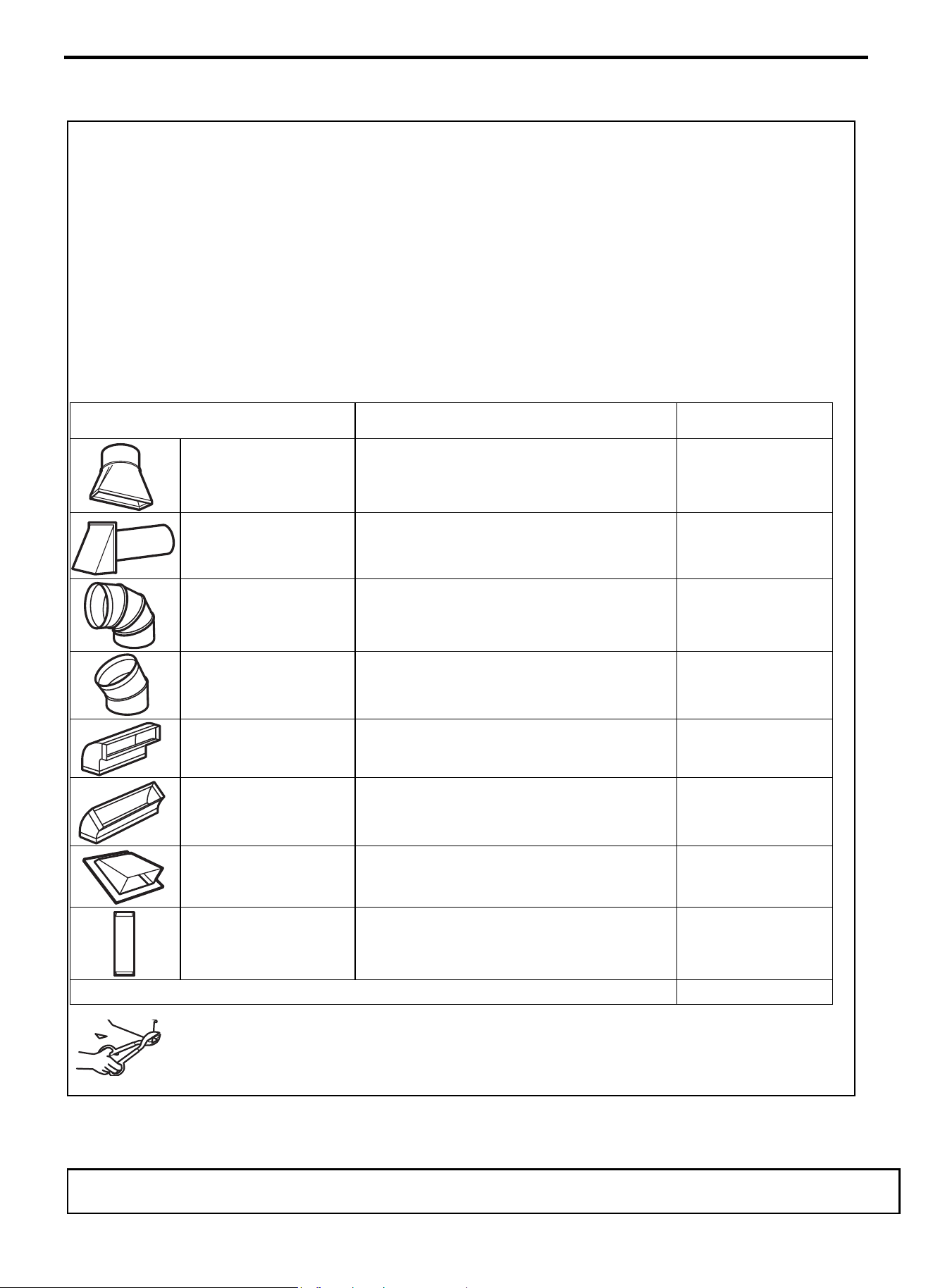
DUCT PIECES
EQUIVALENT
LENGTH
x
NUMBER
USED
=
EQUIVALENT
LENGTH
Rectangular-to-Round
Transition Adaptor*
5 Ft. (1.5 m) x ( ) = Ft. or m
Wall Cap 40 Ft. (12.2 m) x ( ) = Ft. or m
90° Elbow 10 Ft. (3 m) x ( ) = Ft. or m
45° Elbow 5 Ft. (1.5 m) x ( ) = Ft. or m
90° Elbow 25 Ft. (7.6 m) x ( ) = Ft. or m
45° Elbow 5 Ft. (1.5 m) x ( ) = Ft. or m
Roof Cap 24 Ft. (7.3 m) x ( ) = Ft. or m
Straight Duct 6“ (15.2 cm)
Round or 3
14“ x 10“
(8.2 x 25.4 cm Rectangular)
1 Ft. (0.3 m) x ( ) = Ft. or m
Total Ductwork
=
Ft. or m
* IMPORTANT: If a rectangular-to-round transition adaptor
is used, the bottom corners of the damper will have to be cut
to fit, using the tin snips, in order to allow free movement of
the damper.
Equivalent lengths of duct pieces are based on actual tests and reflect
requirements for good venting performance with any vent hood.
EXTERNAL EXHAUST DUCTING
OUTSIDE TOP EXHAUST (EXAMPLE ONLY)
The following chart describes an example of one possible ductwork installation.
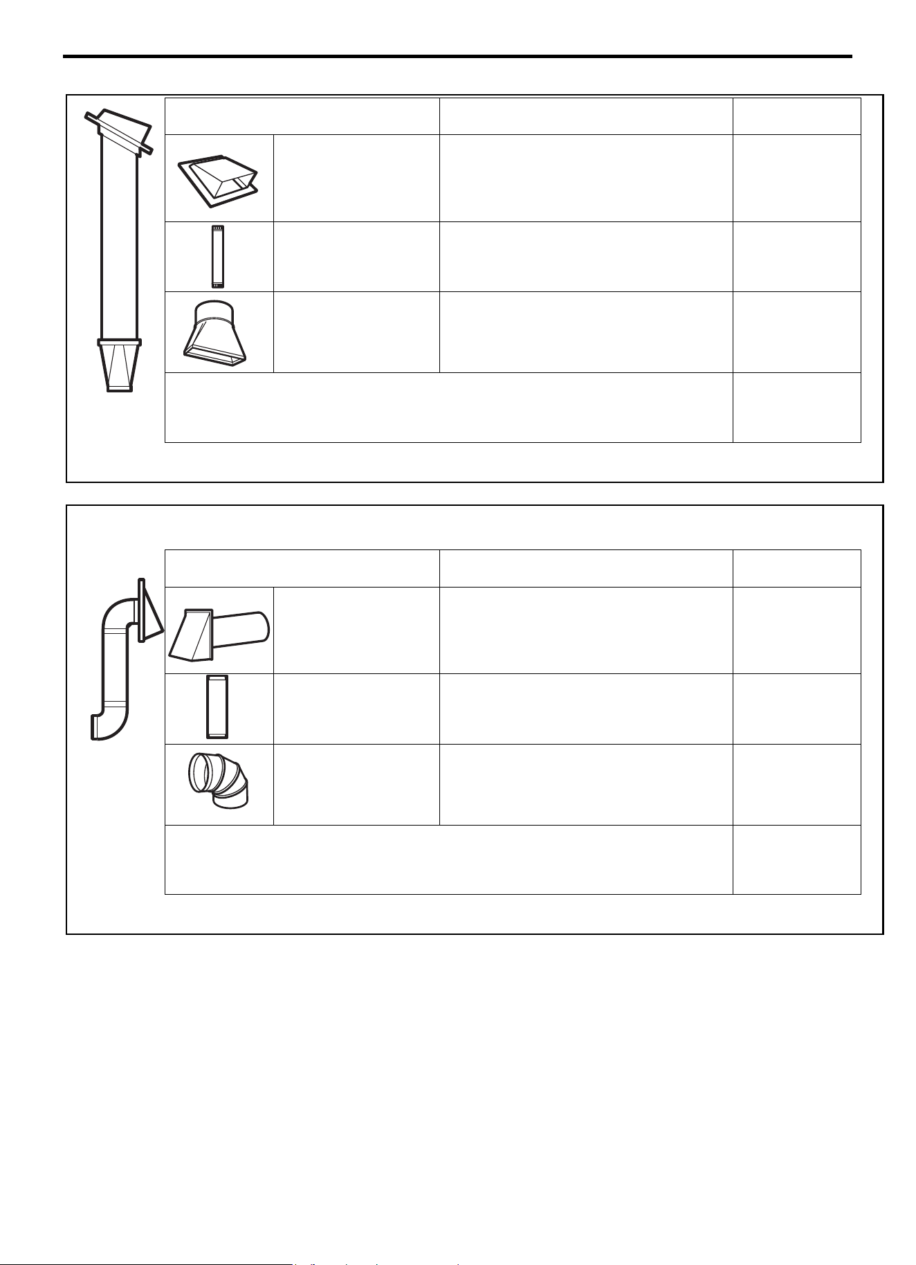
Installation Instruction
EN-31
DUCT PIECES
EQUIVALENT
LENGTH
x
NUMBER
USED
=
EQUIVALENT
LENGTH
Roof Cap
24 Ft. (7.3 m) x (1) = 24 Ft. (7.3 m)
12 Ft. (3.6 m) Straight Duct
(6”/15.2 cm Round)
12 Ft. (3.6 m) x (1) = 12 Ft. (3.6 m)
Rectangular
-to-Round
Transition Adaptor*
5 Ft. (1.5 m) x (1) = 5 Ft. (1.5 m)
Equivalent lengths of duct pieces are based on actual tests and
reflect requirements for good venting performance with any vent
hood.
Total Length = 41 Ft. (12.5 m)
* IMPORTANT: If a rectangular-to-round transition adaptor is used, the bottom corners of the damper will have to be cut to
fit, using the tin snips, in order to allow free movement of the damper.
OUTSIDE BACK EXHAUST (EXAMPLE ONLY)
The following chart describes an example of one possible ductwork installation.
DUCT PIECES
EQUIVALENT
LENGTH
x
NUMBER
USED
=
EQUIVALENT
LENGTH
Wall Cap
40 Ft. (12.2 m) x (1) = 40 Ft. (12.2 m)
3 Ft. Straight Duct
(31/4” x 10”/8.2 x 25.4 cm
Rectangular)
3 Ft. (0.9 m) x (1) = 3 Ft. (0.9 m)
90° Elbow
10 Ft. (3 m) x (2) = 20 Ft. (3 m)
Equivalent lengths of duct pieces are based on actual tests and
reflect requirements for good venting performance with any vent
hood.
Total Length = 63 Ft. (19.2 m)
NOTE: For back exhaust, care should be taken to align exhaust with space between studs, or wall should be prepared at the
time it is constructed by leaving enough space between the wall studs to accommodate exhaust.
Installation Instruction
EN-32
A OUTSIDE TOP EXHAUST (Vertical Duct)
INSTALLATION
OVERVIEW
A1. Attach Mounting Plate to Wall A2.
Prepare Top Cabinet
A3. Adapting Microwave Blower for
Outside Top Exhaust
A4. Check Damper Operation
A5. Mount Microwave Oven A6. Adjust
Exhaust Adaptor A7. Connect Ductwork
IMPORTANT NOTES:
• Make sure the screws for the blower
motor and blower plate are securely
tightened when they are reinstalled.
This will help to prevent excessive
vibration.
• Make sure the motor wiring has been
properly routed and secured, and that
the wires are not pinched.
A1. ATTACH THE MOUNTING PLATE TO
THE WALL
Attach the plate to the wall using toggle bolts. At least one wood
screw must be used to attach the plate to a wall stud.
1 Remove the toggle wings from the bolts.
2 Insert the bolts into the mounting plate through the holes
designated to go into drywall and reattach the toggle wings to
¾”
(19 mm) onto each bolt.
To use toggle bolts:
3 Place the mounting plate against the wall and insert the toggle
wings into the holes in the wall to mount the plate.
NOTE: Before tightening toggle bolts and wood screw, make
sure the bottom of the mounting plate touch the bottom of the
cabinet when pushed flush against the wall and that the plate is
properly centered under the cabinet.
CAUTION: Be careful to avoid pinching fingers between the
back of the mounting plate and the wall.
4 Tighten all bolts. Pull the plate away from the wall to help
tighten the bolts.
Spacing for Toggles More
Than Wall Thickness
Mounting
Plate
Toggle Wings
Toggle
Bolt
Bolt End
Wall
3/8"TO
EDG
E
NOTE: IT IS VERY
I
MPOR
TANT TO
READ AND FOLLOW
THE
D
IRECTIONS
IN THE INSTALLAT
ION INSTRU
CTI
O
N
S
BE
FO
RE PR
O
CEEDING
WITH T
H
IS
REAR W
ALL TEM
PLATE
.
Th
i
s
R
ea
rWa
ll Template ser
v
e
s to positio
n th
e
botto
m
mounting platea
nd
to loc
ate th
e hor
i
z
on
tal exhau
st
ou
t
let.
1. Us
e a l
evelto
ch
ec
k
th
at the
tem
pla
te is po
s
itioned
a
ccu
r
ately
.
2. L
oc
ate
andmar
k at lea
st o
nes
tu
d on th
e
le
ft or
r
ight side of the cen
te
rli
ne
.
It is importa
n
t to u
se at leas
t
one wood
scre
w
mounted firmly
i
n a s
tud
to supp
ort the weight
ofthe mic
r
ow
a
ve. Mark t
w
o
a
dditi
on
a
l, ev
en
ly
spa
c
ed
lo
c
atio
ns
fo
r the
s
uppl
ied to
g
gle bol
t
s.
3. Dri
ll
h
ol
es in
the mar
k
ed locatio
ns
.Wher
e t
h
er
e is
a s
tud, dr
il
l
a 3/1
6"
h
ol
e fo
r wood scr
ews. F
or
holes
that
do
n
o
t line upw
ith
a
s
tud, dr
il
l 5/8" h
oles
fo
r
toggl
e bolts
.
DO NOT
IN
S
T
AL
L
T
HE MO
U
NTIN
G P
L
ATE
AT
T
HIS
T
IME.
4. Re
move
th
e template fr
o
m
the rea
r
wal
l.
5.Review
the In
s
tall
a
tionInst
ructio
n bo
ok for
y
our
insta
l
l
ation si
tua
t
i
on
.
Locate and mar
k holes
to align with holes
in t
he
mountingp
late.
IMPO
RTANT
:
LOCATE
AT LEA
ST
O
N
E
STUD
O
N EI
THER
SI
D
E O
F
THE
CENTE
R
LI
N
E.
MARK
T
HE LOCATIO
NF
O
R 2 ADDITIONAL, EV
ENL
Y
SP
ACED TOGGLE BO
LTS IN THE MOUN
TING
PLATE
AREA
.
Locate and mar
k holes to ali
gn with holes
in t
he
mountingplate.
IMP
ORTANT
:
LOC
A
TE AT LEAST O
NE
STUD
O
N EI
THER SI
D
E O
F
TH
E
CENT
ERLI
N
E
.
MARK
THE LOCATIO
N
FOR 2 ADDITION
A
L, EVENLY
SPACEDTOGGLE BOLTS IN THE MO
UNTING PLATE
AREA.
Trim the r
e
ar wall tem
plat
e alongthe do
tt
ed line.
Trim the rear
wall tem
pla
t
e alongthe dotted lin
e.
12"
4"
Da
r
l
evue
lt
a
a
la
ho
j
a
pa
ra
consu
l
t
ar
la
ver
sión
en
Espa
ñol.
24"
Installation Instruction
EN-33
A2. USE TOP CABINET TEMPLATE FOR
PREPARATION OF TOP CABINET
You need to drill holes for the top support screws, a hole large
enough for the power cord to fit through, and a cutout large enough
for the exhaust adaptor.
• Read the instructions on the TOP CABINET TEMPLATE.
• Tape it underneath the top cabinet.
• Drill the holes, following the instructions on the TOP CABINET
TEMPLATE.
CAUTION: Wear safety goggles when drilling holes in the cabinet
bottom.
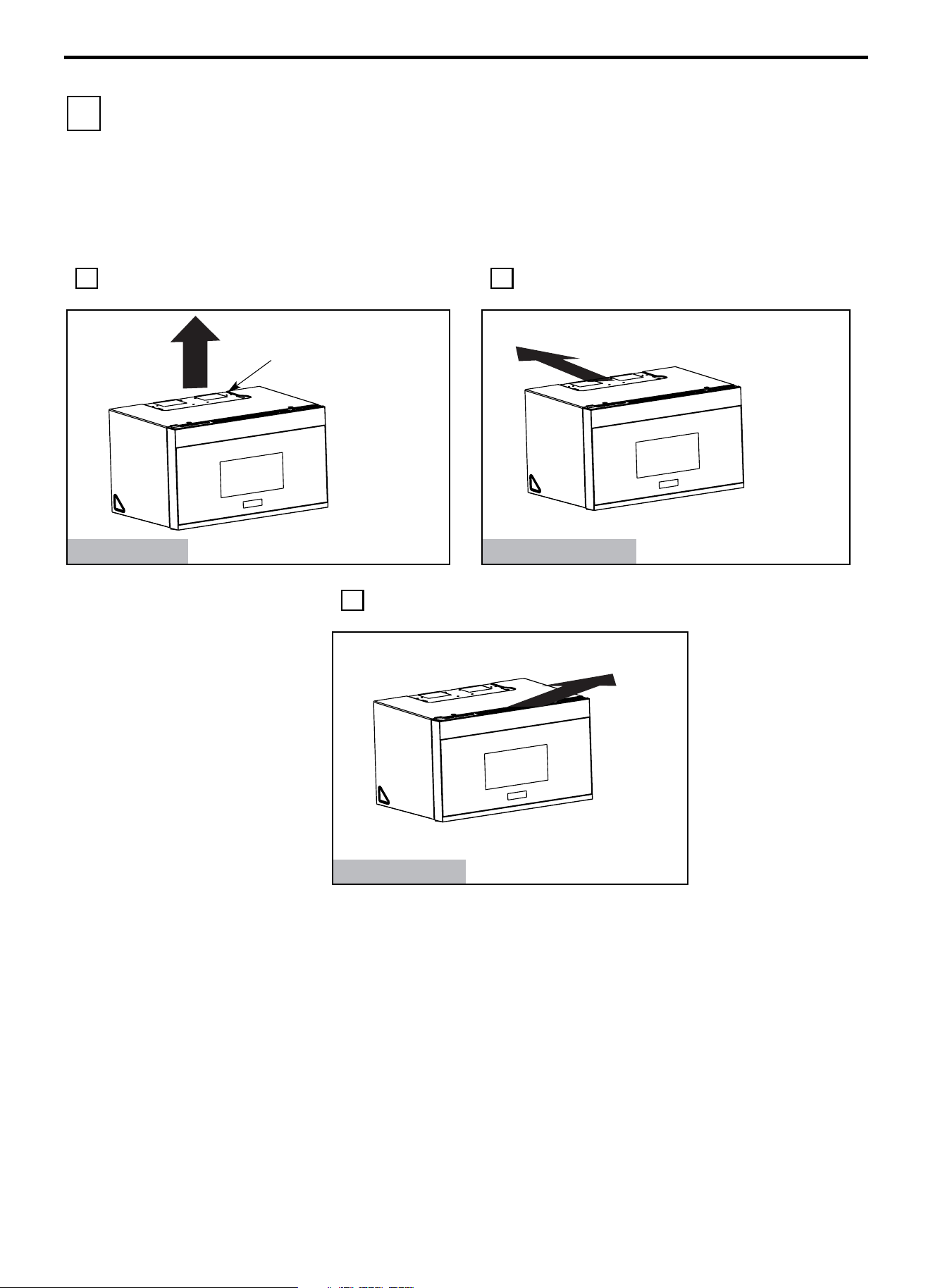
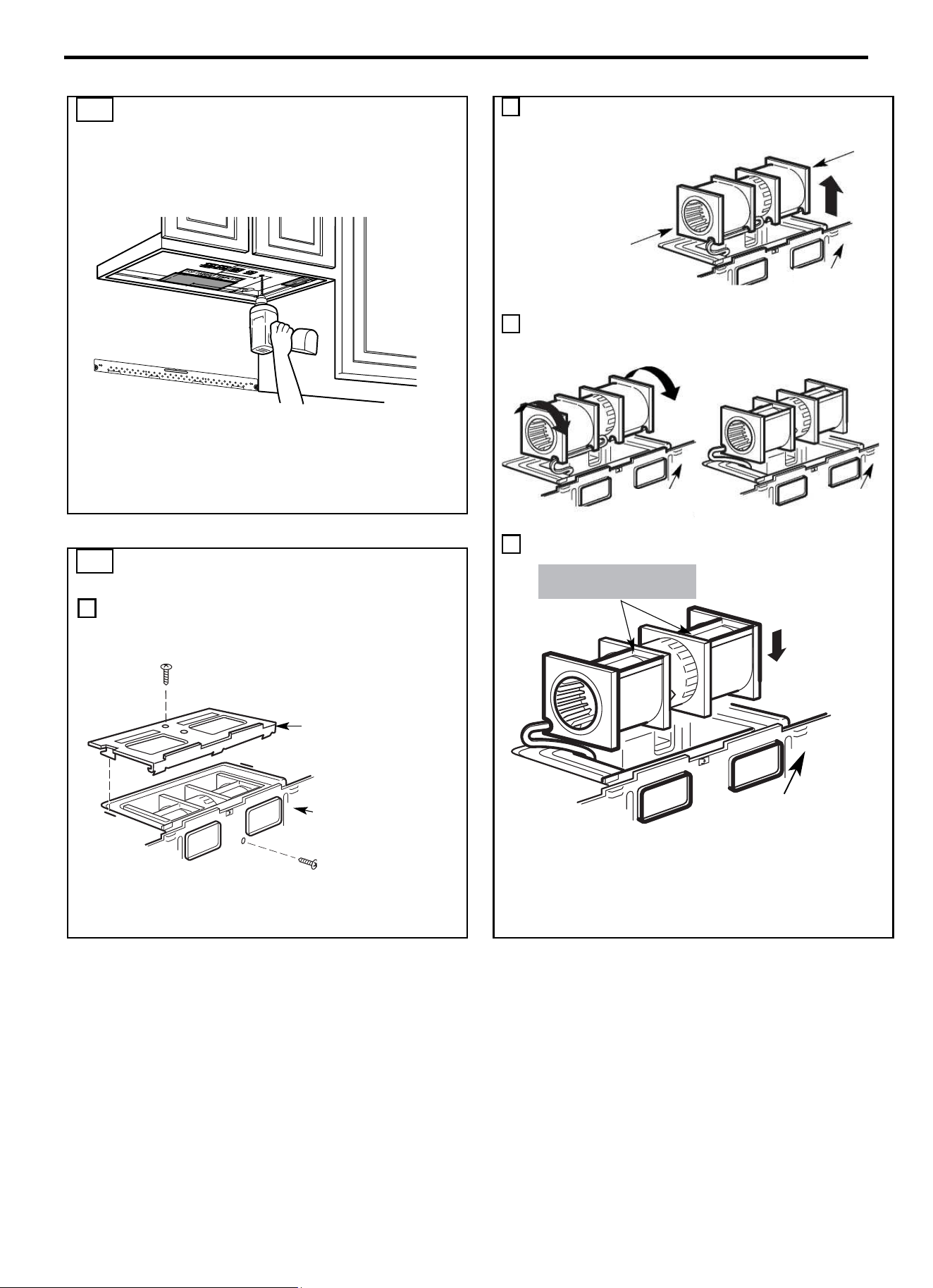
2
Carefully pull out the blower unit. The wires will extend far
enough to allow you to adjust the blower unit.
3 Roll the blower unit 90° so that fan blade openings are facing
out the top of the microwave.
4 Place the blower unit back into the opening.
CAUTION: Do not pull or stretch the blower unit
wiring. Make sure the wires are not pinched, and
that they are properly secured.
A3. ADAPTING MICROWAVE BLOWER
FOR OUTSIDE TOP EXHAUST
1 Place the microwave in its upright position, with the top of the
unit facing up.
Remove the screw that holds the blower plate to the
microwave. Remove and save the screw holding the blower
motor to the microwave.
AFTER: Fan Blade
Openings Facing Top
Back of
Microwave
Back of
Microwave
Back of
Microwave
Before Rotation
After Rotation
End B
End A
Back of
Microwave
Back of
Microwave
Blower Plate
Blower Motor
Installation Instruction
EN-34
A3. ADAPTING MICROWAVE BLOWER FOR
OUTSIDE TOP EXHAUST
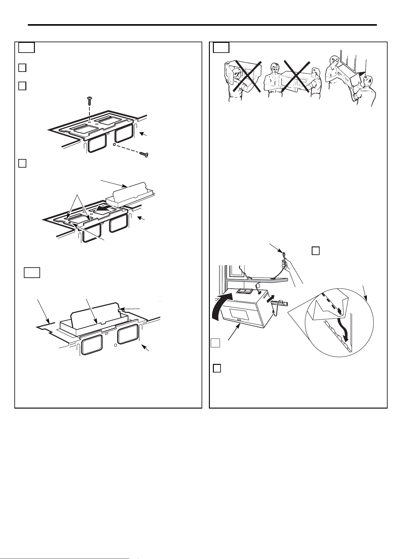
5 Secure blower unit to microwave with the screw removed in Step 1.
Make sure the screw is tight.
6 Replace blower plate with the screw removed in Step 1. Make sure
the screw is tight.
7 Attach the exhaust adaptor to the top of the blower plate by sliding it
into the guides of the blower plate.
Push in securely until it is in the locking tabs. Take care to assure
that the damper hinge is installed so that the damper swings freely.
A4. CHECK FOR PROPER DAMPER
OPERATION
• Make sure tape securing damper is removed and damper pivots
easily before mounting microwave.
• You will need to make adjustments to assure proper alignment with
your house exhaust duct after the microwave is installed.
A5. MOUNT THE MICROWAVE OVEN
FOR EASIER INSTALLATION AND PERSONAL SAFETY,
WE RECOMMEND THAT TWO PEOPLE INSTALL THIS
MICROWAVE OVEN.
IMPORTANT: Do not grip or use the handle or heat shield
during installation. Do not remove the cardboard spacers
between the heat shield and door.
NOTE: If your cabinet is metal, use the nylon grommet around the
power cord hole to prevent cutting of the cord.
NOTE: We recommend using filler blocks if the cabinet front
hangs below the cabinet bottom shelf.
IMPORTANT: If filler blocks are not used, case damage may
occur from overtightening screws.
3 Insert a self-aligning screw through top center cabinet hole.
Temporarily secure the oven by turning the screw at least two
full turns after the threads have engaged. (It will be completely
tightened later.) Be sure to keep power cord tight. Be careful
not to pinch the cord, especially when mounting flush to
bottom of cabinet.
Back of
Microwave
Blower Plare
Exhaust Adaptor
Damper
Adaptor
Guide
Locking Tab
Back of
Microwave
Back of
Microwave
NOTE: When mounting
the microwave oven,
thread power cord through
hole in bottom of top
cabinet. Keep it tight
throughout Steps 1
-
3. Do
not pinch cord or lift oven
by pulling cord.
1 Lift microwave, tilt it
forward, and hook
slots at back bottom
edge onto four lower
tabs of mounting plate.
Rotate front of oven up
against cabinet bottom.
2
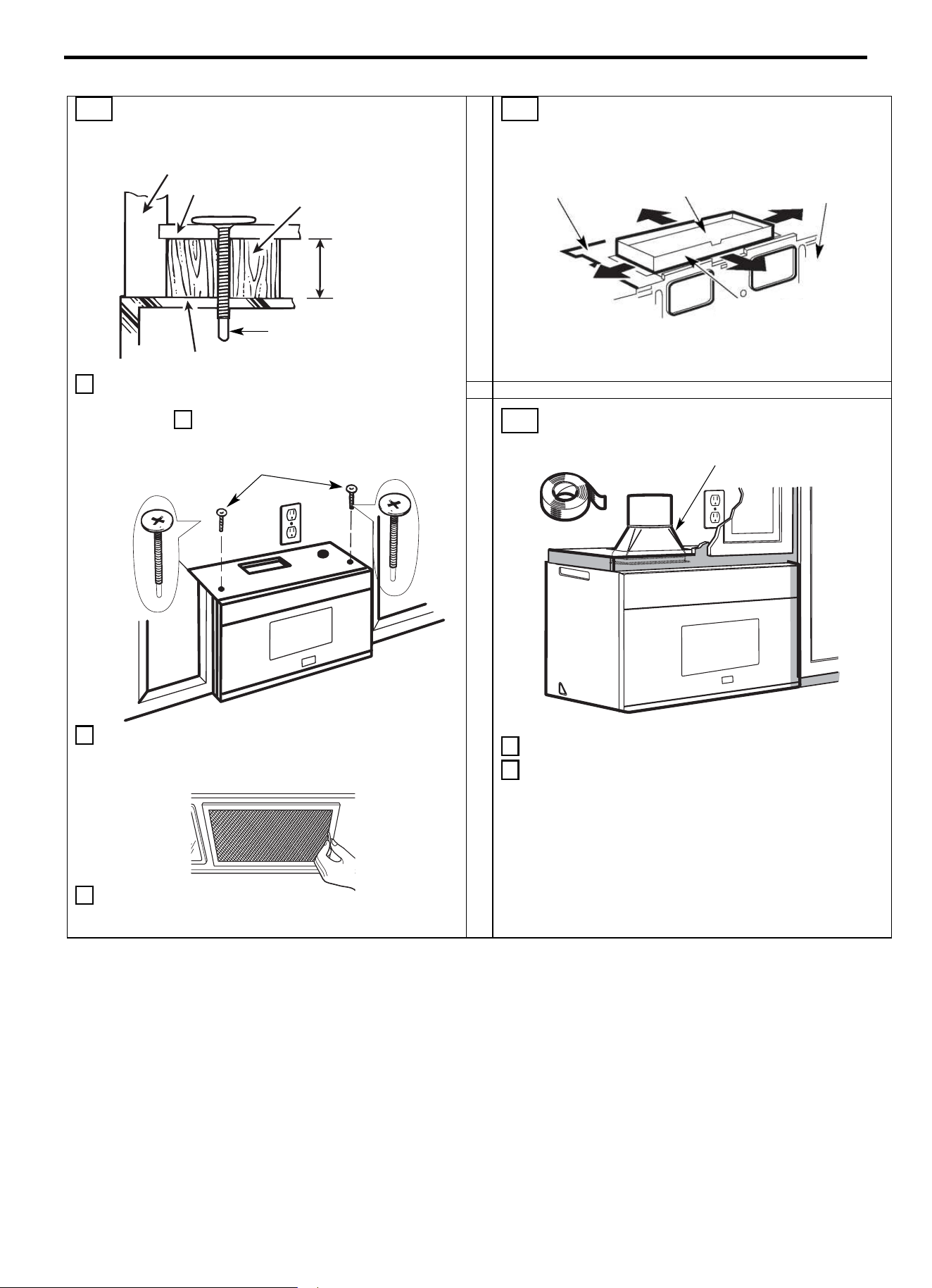
Installation Instruction
EN-35
A5. MOUNT THE MICROWAVE OVEN
(cont.)
4 Attach the microwave oven to the top cabinet.
5 Insert 2 self-aligning screws through outer
top cabinet holes. Turn two full turns on each
screw.
6 Tighten the outer two screws to the top of the microwave oven.
(While tightening screws, hold the microwave oven in place
against the wall and the top cabinet.)
7 Install grease filters. See the Use and Care packed with the
microwave.
A6. ADJUST THE EXHAUST ADAPTOR
Open the top cabinet and adjust the exhaust adaptor to connect to
the house duct.
A7. CONNECTING DUCTWORK
1 Extend the house duct down to connect to the exhaust adaptor.
2 Seal exhaust duct joints using furnance duct tape for high
temperature applications.
Cabinet Front
Filler Block
Cabinet Bottom Shelf
Equivalent to
Depth of
Cabinet
Recess
Self-Aligning Screw
Microwave Oven Top
Blower Plate
Back of
Microwave
Damper
For Front-to-Back or Side-
to
-Side Adjustment, Slide
the Exhaust Adaptor as
Needed
House Duct
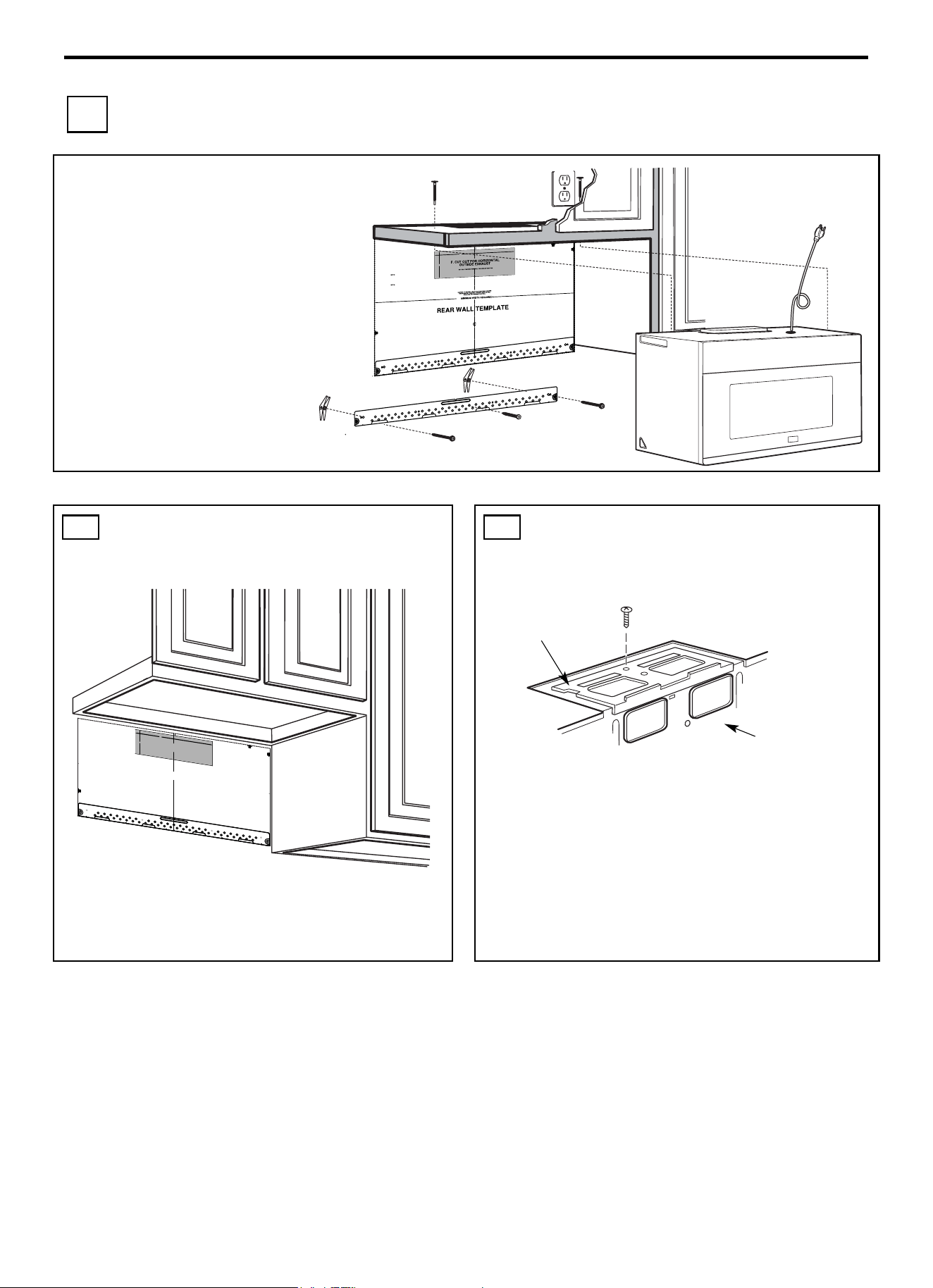
Installation Instruction
EN-36
B OUTSIDE BACK EXHAUST (Horizontal Duct)
INSTALLATION OVERVIEW
B1. Prepare Rear Wall
B2. Remove Blower Plate
B3. Attach Mounting Plate to Wall
B4. Prepare Top Cabinet
B5. Adjust Blower
B6. Mount the Microwave Oven
IMPORTANT NOTES:
• Make sure the screws for the blower
motor and blower plate are securely
tightened when they are reinstalled. This
will help to prevent excessive vibration.
• Make sure the motor wiring has been
properly routed and secured, and that the
wires are not pinched.
B1. PREPARING THE REAR WALL FOR
OUTSIDE BACK EXHAUST
You need to cut an opening in the rear wall for outside exhaust.
Read the instructions on the REAR WALL TEMPLATE.
• Tape it to the rear wall.
• Cut the opening, following the instructions of the REAR WALL
TEMPLATE.
B2. REMOVE BLOWER PLATE
Remove and save the screw that holds the blower plate to the
microwave. Lift off the blower plate.
Blower Plate
Back of
Microwave
3/8"TO
EDG
E
NOTE: IT IS VERY
I
MPOR
TANT TO
READ AND FOLLOW
THE
D
IRECTIONS
IN THE INSTALLAT
ION INSTRU
CTI
O
N
S
BE
FO
RE PR
O
CEEDING
WITH T
H
IS
REAR W
ALL TEM
PLATE
.
Th
i
s
R
ea
rWa
ll Template ser
v
e
s to positio
n th
e
botto
m
mounting platea
nd
to loc
ate th
e hor
i
z
on
tal exhau
st
ou
t
let.
1. Us
e a l
evelto
ch
ec
k
th
at the
tem
pla
te is po
s
itioned
a
ccu
r
ately
.
2. L
oc
ate
andmar
k at lea
st o
nes
tu
d on th
e
le
ft or
r
ight side of the cen
te
rli
ne
.
It is importa
n
t to u
se at leas
t
one wood
scre
w
mounted firmly
i
n a s
tud
to supp
ort the weight
ofthe mic
r
ow
a
ve. Mark t
w
o
a
dditi
on
a
l, ev
en
ly
spa
c
ed
lo
c
atio
ns
fo
r the
s
uppl
ied to
g
gle bol
t
s.
3. Dri
ll
h
ol
es in
the mar
k
ed locatio
ns
.Wher
e t
h
er
e is
a s
tud, dr
il
l
a 3/1
6"
h
ol
e fo
r wood scr
ews. F
or
holes
that
do
n
o
t line upw
ith
a
s
tud, dr
il
l 5/8" h
oles
fo
r
toggl
e bolts
.
DO NOT
IN
S
T
AL
L
T
HE MO
U
NTIN
G P
L
ATE
AT
T
HIS
T
IME.
4. Re
move
th
e template fr
o
m
the rea
r
wal
l.
5.Review
the In
s
tall
a
tionInst
ructio
n bo
ok for
y
our
insta
l
l
ation si
tua
t
i
on
.
Locate and mar
k holes
to align with holes
in t
he
mountingp
late.
IMPO
RTANT
:
LOCATE
AT LEA
ST
O
N
E
STUD
O
N EI
THER
SI
D
E O
F
THE
CENTE
R
LI
N
E.
MARK
T
HE LOCATIO
NF
O
R 2 ADDITIONAL, EV
ENL
Y
SP
ACED TOGGLE BO
LTS IN THE MOUN
TING
PLATE
AREA
.
Locate and mar
k holes to ali
gn with holes
in t
he
mountingplate.
IMP
ORTANT
:
LOC
A
TE AT LEAST O
NE
STUD
O
N EI
THER SI
D
E O
F
TH
E
CENT
ERLI
N
E
.
MARK
THE LOCATIO
N
FOR 2 ADDITION
A
L, EVENLY
SPACEDTOGGLE BOLTS IN THE MO
UNTING PLATE
AREA.
Trim the r
e
ar wall tem
plat
e alongthe do
tt
ed line.
Trim the rear
wall tem
pla
t
e alongthe dotted lin
e.
12"
4"
Da
r
l
evue
lt
a
a
la
ho
j
a
pa
ra
consu
l
t
ar
la
ver
sión
en
Espa
ñol.
24"
3/8" TO EDGE
NOTE: IT IS VE
RY IMPORTANT TO
READ AND FOLLOW THE DIRECTIONS
IN THE INSTALLATION INSTRUCTIONS
BEFORE PROCEEDING WITH THIS
REAR WALL TEMPLATE.
This Rear Wall Template serves to position the bottom
mounting plate and to locate the horizontal exhaust
outlet.
1. Use a level to check that the template is positioned
accurately.
2. Locate and mark at least one stud on the left or
right side of the centerline.
It is important to use at least one wood
screw mounted firmly in a stud to support the weight
of the microwave. Mark two additional, evenly spaced
locations for the supplied toggle bolts.
3. Drill holes in the marked locations. Where there is
a stud, drill a 3/16" hole for wood screws. For holes
that do not line up with a stud, drill 5/8" holes for
toggle bolts.
DO NOT INSTALL THE MOUNTING PLATE
AT THIS TIME.
4. Remove the template from the rear wall.
5. Review the Installation Instruction book for your
installation situation.
Locate and mark holes to align with holes in the
mounting plate.
IMPORTANT:
LOCATE
AT LEAST ON
E STUD ON EITHER SIDE OF
THE CENTERLINE.
MARK THE LOCATION FOR
2 ADDITIONAL, EVENLY
SPACED TOGGLE BOLTS IN THE MOUNTING PLATE
AREA.
Locate and mark holes to align with holes in the
mounting plate.
IMPORTA
NT:
LOCATE AT LEAST ONE STUD ON EITHER SIDE OF
THE CENTERLINE.
MARK THE LOCATION FOR 2 ADDITIONAL, EVENLY
SPACED TOGGLE BOLTS IN THE MOUNTING PLATE
AREA.
Trim the rear wall template along the dotted line.
Trim the rear wall template along the dotted line.
12"
4"
Darle vuelta a la hoja para consultar la
versión en Español.
24"
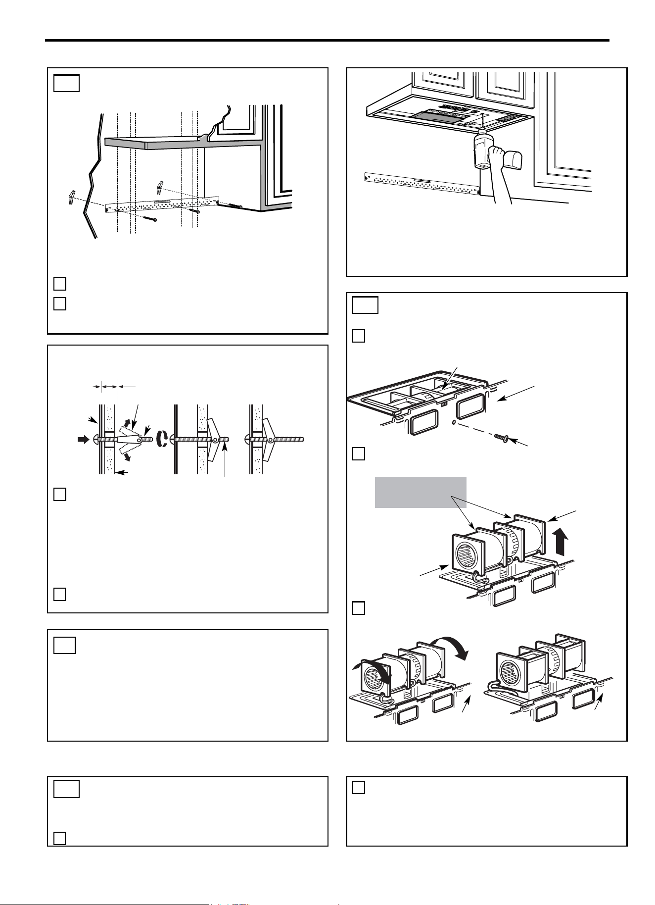
Installation Instruction
EN-37
B3. ATTACH THE MOUNTING PLATE TO
THE WALL
Attach the plate to the wall using toggle bolts.
At least one wood screw must be used to attach the plate to a wall
stud.
1 Remove the toggle wings from the bolts.
2 Insert the bolts into the mounting plate through the holes
designated to go into drywall and reattach the toggle wings to
¾” (19 mm) onto each bolt.
• Read the instructions on the TOP CABINET TEMPLATE.
• Tape it underneath the top cabinet.
• Drill the holes, following the instructions on the TOP
CABINET TEMPLATE.
CAUTION: Wear safety goggles when drilling holes in the cabinet
bottom.
B5. ADAPTING MICROWAVE BLOWER
FOR OUTSIDE BACK EXHAUST
1 Remove and save screw that holds blower motor to
microwave.
2 Carefully pull out the blower unit. The wires will extend far
enough to allow you to adjust the blower unit.
3 Roll the blower unit 90°
To use toggle bolts:
3 Place the mounting plate against the wall and insert the toggle
wings into the holes in the wall to mount the plate.
NOTE: Before tightening toggle bolts and wood screw, make
sure the bottom of the mounting plate touch the bottom of the
cabinet when pushed flush against the wall and that the plate is
properly centered under the cabinet.
CAUTION: Be careful to avoid pinching fingers between the
back of the mounting plate and the wall.
4 Tighten all bolts. Pull the plate away from the wall to help
tighten the bolts.
B4. USE TOP CABINET TEMPLATE FOR
PREPARATION OF TOP CABINET
You need to drill holes for the top support screws and a hole large
enough for the power cord to fit through.
B5. ADAPTING MICROWAVE BLOWER
FOR OUTSIDE BACK EXHAUST
(cont.)
4
Rotate blower unit counterclockwise 180°.
8 Place the blower unit back into the opening.
Back of
Microwave
Back of
Microwave
Before Rotation
After Rotation
End A
End B
Before: Fan Blade
Openings Facing
Forward
Blower Motor
Blower Motor
Screw
Back of Microwave
Spacing for Toggles More
Than Wall Thickness
Mounting
Plate
Toggle Wings
Toggle
Bolt
Bolt End
Wall
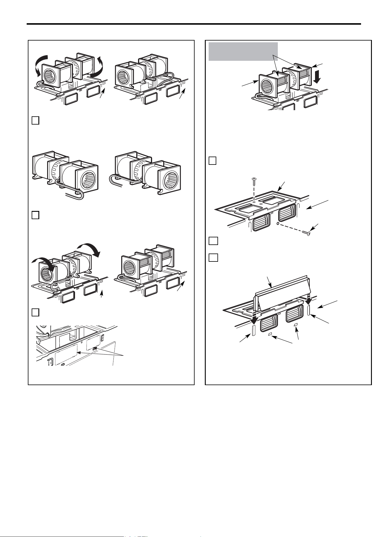
Installation Instruction
EN-38
5 Gently remove the wires from the grooves.
Reroute the wires through grooves on other side of the blower
unit.
6 Roll the blower unit 90° so that fan blade openings are facing
out the back of the microwave.
7 Remove the knockout plates in the back of the unit
with snips. (For some models)
CAUTION: Do not pull or stretch the blower unit
wiring. Make sure the wires are not pinched, and
that they are properly secured.
NOTE: The blower unit exhaust openings should
match exhaust openings on rear of microwave
oven.
9 Secure the blower unit to the microwave with the original
screw.
10 Replace the blower plate in the same position as before with
the screw. Make sure the screw is tight.
11 Attach the exhaust adaptor to the rear of the oven by sliding it
into the guides at the top center of the back of the oven.
Push in securely until it is in the lower locking tabs. Take care to
assure that the damper hinge is installed so that it is at the top and
that the damper swings freely.
Back of Microwave
Snip all 4 webs on each
knockout panel and remove
the metal knockouts for rear
airflow. Please take care to
remove any sharp edges
created from removing the
knockout plates.
Back of
Microwave
Back of
Microwave
Before Rolling
After Rolling
Wires Routed Through Right Side
Wires Routed Through Left Side
Before Rerouting
After Rerouting
Back of
Microwave
Back of
Microwave
Before Rotation
After Rotation
Adaptor
Guide
Locking Tab
Back of
Microwave
Guide
Back of
Microwave
Blower Plate
Blower Motor
End B
End A
AFTER: Fan Blade
Openings Facing Back
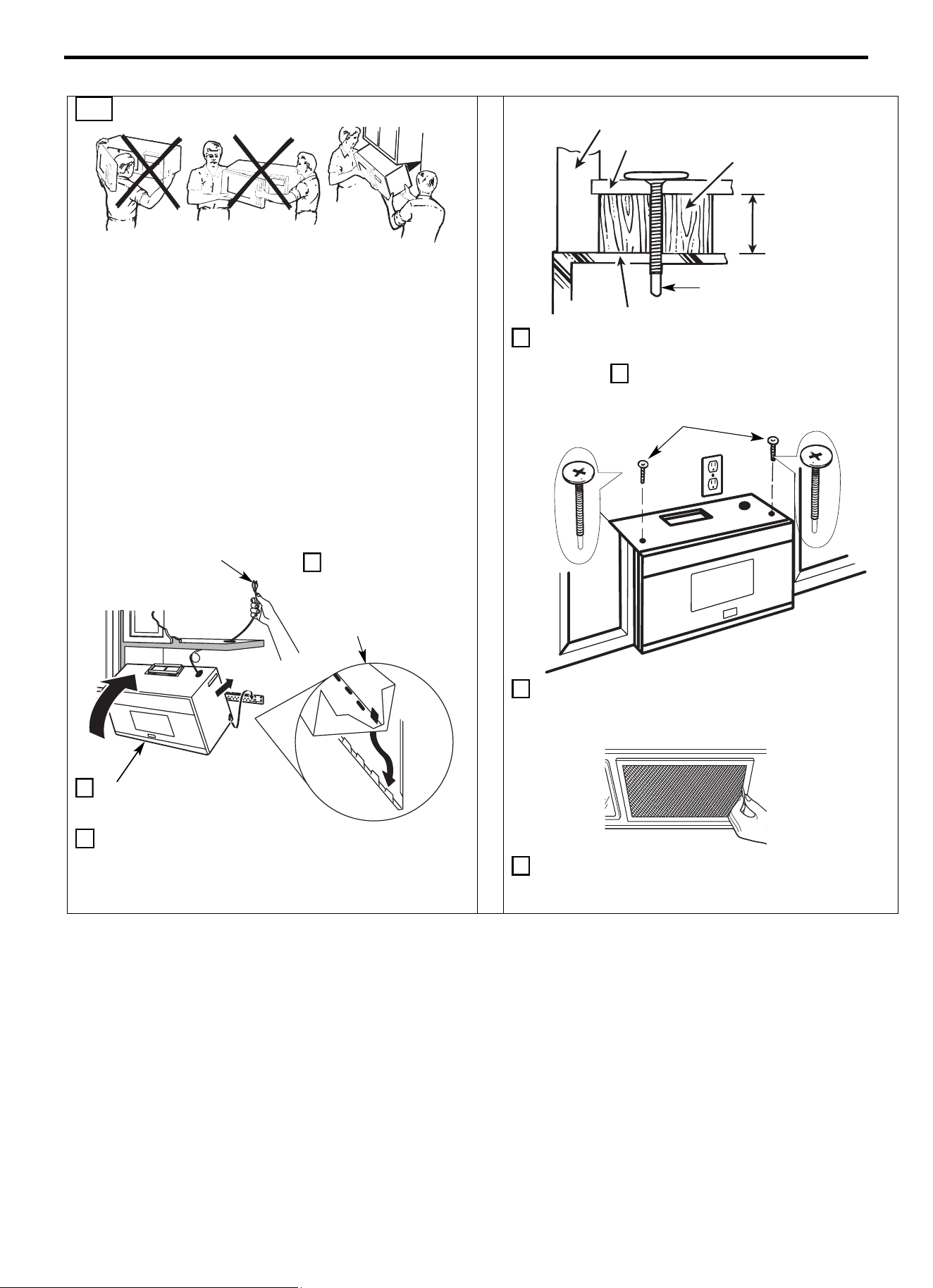
Installation Instruction
EN-39
B5. MOUNT THE MICROWAVE OVEN
FOR EASIER INSTALLATION AND PERSONAL SAFETY,
WE RECOMMEND THAT TWO PEOPLE INSTALL THIS
MICROWAVE OVEN.
IMPORTANT: Do not grip or use the handle or heat shield
during installation. Do not remove the cardboard spacers
between the heat shield and door.
NOTE: If your cabinet is metal, use the nylon grommet around the
power cord hole to prevent cutting of the cord.
NOTE: We recommend using filler blocks if the cabinet front
hangs below the cabinet bottom shelf.
IMPORTANT: If filler blocks are not used, case damage may
occur from overtightening screws.
3 Insert a self-aligning screw through top center cabinet hole.
Temporarily secure the oven by turning the screw at least two full
turns after the threads have engaged. (It will be completely tightened
later.) Be sure to keep power cord tight. Be careful not to pinch
the cord, especially when mounting flush to bottom of cabinet.
4 Attach the microwave oven to the top cabinet.
5 Insert 2 self-aligning screws through outer
top cabinet holes. Turn two full turns on
each screw.
6 Tighten the outer two screws to the top of the microwave
oven. (While tightening screws, hold the microwave oven in
place against the wall and the top cabinet.)
7 Install grease filters. See the Use and Care packed with the
microwave.
NOTE: When mounting
the microwave oven,
thread power cord through
hole in bottom of top
cabinet. Keep it tight
thro
ughout Steps 1-
3. Do
not pinch cord or lift oven
by pulling cord.
1 Lift microwave, tilt it
forward, and hook
slots at back bottom
edge onto four lower
tabs of mounting plate.
2 Rotate front of oven up
against cabinet bottom.
Cabinet Front
Filler Block
Cabinet Bottom Shelf
Equivalent to
Depth of
Cabinet
Recess
Self-Aligning Screw
Microwave Oven Top
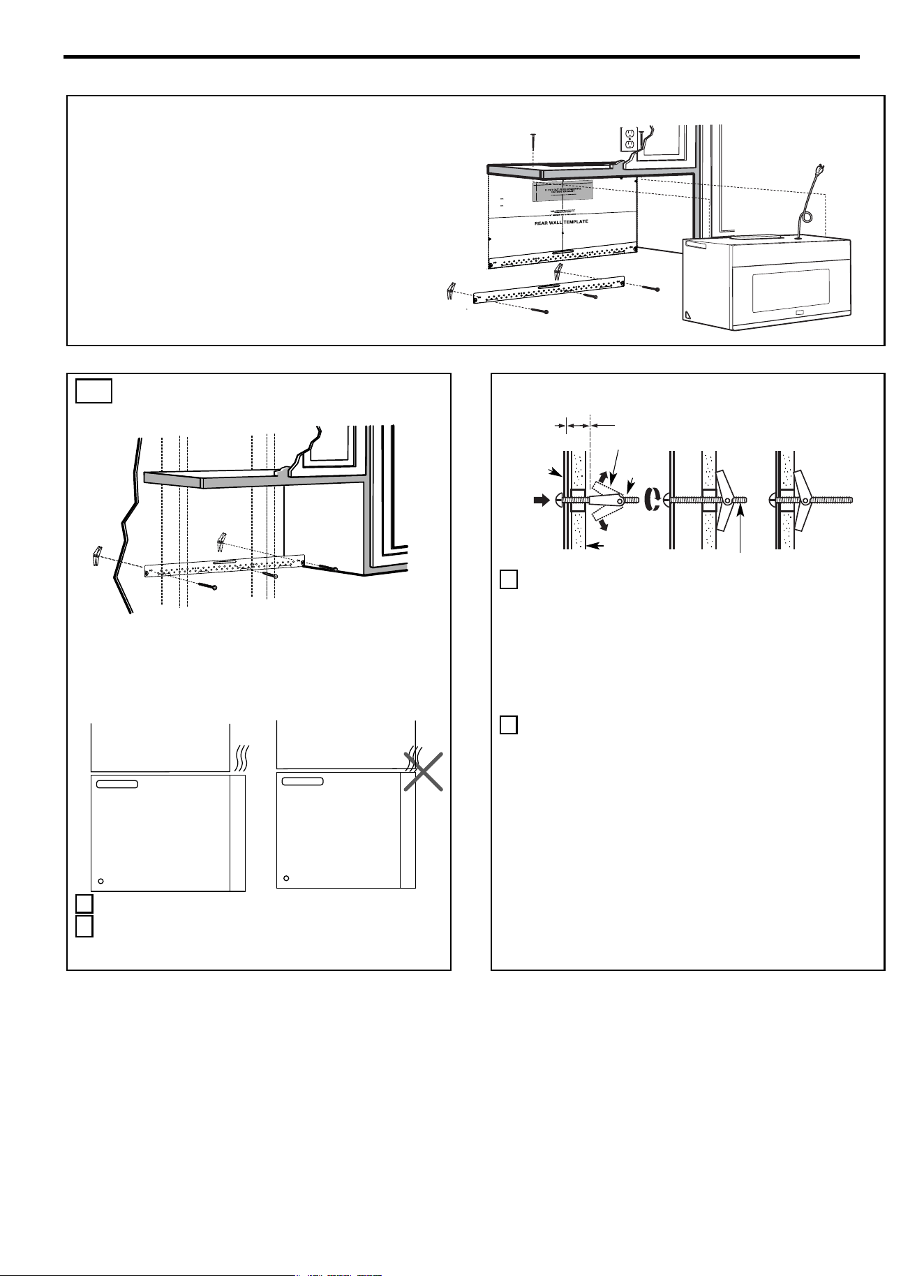
Installation Instruction
EN-40
INSTALLATION OVERVIEW
C1. Attach Mounting Plate to Wall
C2. Prepare Top Cabinet
C3. Check Blower Plate
C4. Mount the Microwave Oven
C5. Install or change Charcoal Filter
IMPORTANT NOTES:
• Make sure the screws for the blower motor and blower plate
are securely tightened when they are reinstalled. This will help
to prevent excessive vibration.
• Make sure the motor wiring has been properly routed and
secured, and that the wires are not pinched.
C1. ATTACH THE MOUNTING PLATE
TO THE WALL
Attach the plate to the wall using toggle bolts. At least one wood
screw must be used to attach the plate to a wall stud.
NOTE: If the cabinet depth including the cabinet doors is more
than 13"'' then the unit must be spaced out from wall
using adequate materials supporting 150 Ibs to allow
proper top vent air exhaust/intake.
1 Remove the toggle wings from the bolts.
2 Insert the bolts into the mounting plate through the holes
designated to go into drywall and reattach the toggle wings
to ¾” (19 mm) onto each bolt.
To use toggle bolts:
3 Place the mounting plate against the wall and insert the toggle
wings into the holes in the wall to mount the plate.
NOTE: Before tightening toggle bolts and wood screw, make
sure the bottom of the mounting plate touch the bottom of the
cabinet when pushed flush against the wall and that the plate is
properly centered under the cabinet.
CAUTION: Be careful to avoid pinching fingers between the
back of the mounting plate and the wall.
4 Tighten all bolts. Pull the plate away from the wall to help
tighten the bolts.
Cabinet
Cabinet
Spacing for Toggles More
Than Wall Thickness
Mounting
Plate
Toggle Wings
Toggle
Bolt
Bolt End
Wall
3/8"TO EDG
E
NOTE: IT IS VERY IMPORTANT TO
READ AND FOLLOWTHE DIRECTIO
N
S
IN THE INSTALLAT
ION INSTRU
CTIO
N
S
BE
FO
RE PR
OCEEDING
WITH T
HIS
REAR W
ALL TEM
PLATE.
This RearWall Template serves to position th
e bottom
mou
nting pl
a
teand to loc
ate the hori
z
onta
l e
x
haust
ou
tlet.
1. Use a level
to
check
that the te
m
plate
i
s po
s
itioned
a
ccu
rately.
2. Locate
and
mark at least ones
tu
d on the
le
ft or
r
ight
s
id
e
of th
e centerl
ine
.
It
is impo
rtan
t to u
se at leas
t one
wood
screw
mo
unted
fir
mly
i
n
a
s
tud
to support the weight
of
the mi
cr
owa
ve.
Mar
k
t
w
o ad
di
tion
al, ev
e
nly
spa
ced
locations
f
or the
s
uppl
ied to
g
gle bol
t
s.
3. Dr
ill
h
ol
es in
the m
ar
ked loc
ations
.
Where th
er
e is
a stud, dr
il
l a 3/16" hole for wood screw
s
. For h
o
les
that
do
n
ot line upwith a
s
tud, d
rill 5/8"
holes for
togg
l
e bolts
.
DO NOT INSTALL
THE
MO
U
NTI
NG PLATE
AT
THISTIME.
4. Re
mov
e th
e templa
te fro
m
the rea
r
wall.
5.Review the Installation Instruction book for your
insta
l
l
atio
n si
tuat
i
on
.
Locate and mark holes to align with holes in the
mountingplate.
IMPORTANT:
LOCATE
AT LEA
ST
O
N
E
STUD
ON EI
T
HER
SID
E O
F
THE CENTERLINE.
MARKTHE LOCATION FOR 2 ADDITIONAL, EVENLY
SPACE
D TO
GGLE
BO
LTS IN THE MOUN
TING
PLATE
AREA
.
Locate and mar
k
holes to align with holes
in t
he
mountingplate.
IMP
ORTANT
:
LOCATE AT LEAST O
NE
STUD
O
N EITHER SID
E OF
TH
E
CENT
E
R
LI
N
E
.
MARK
THE LOCATIO
N
FOR 2 ADDITIONAL, EVENLY
SP
ACED
TOGGLE BOLTS IN
THE MO
UNTING PLATE
AREA
.
Trim the rear wall template alongthe do
tted line.
Trim the rear wall template alongthe dotted line.
12"
4"
Darl
evue
lt
aa la ho
j
a
pa
rac
ons
u
lt
ar
la
versión
enE
spa
ño
l.
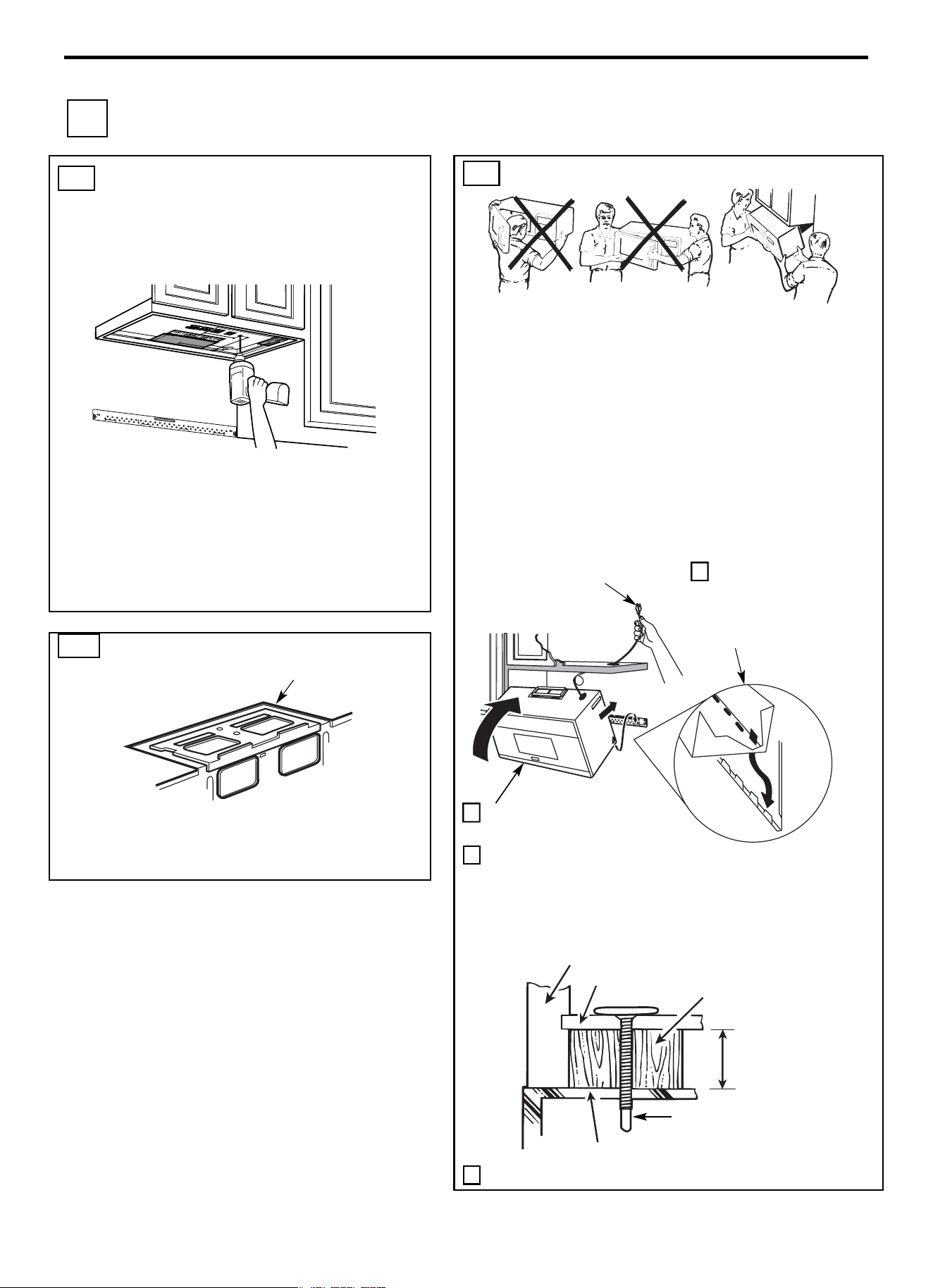
Installation Instruction
EN-41
C2. USE TOP CABINET TEMPLATE
FOR PREPARATION OF TOP
CABINET
You need to drill holes for the top support screws and a hole
large enough for the power cord to fit through.
• Read the instructions on the TOP CABINET TEMPLATE.
• Tape it underneath the top cabinet.
NOTE: Adjust top template accordingly if the microwave is
being spaced out from the wall due to cabinet depth (including
cabinet doors) of more than 13”.
• Drill the holes, following the instructions on the TOP
CABINET TEMPLATE.
CAUTION: Wear safety goggles when drilling holes in the
cabinet bottom.
C4. MOUNT THE MICROWAVE OVEN
FOR EASIER INSTALLATION AND PERSONAL SAFETY, WE
RECOMMEND THAT TWO PEOPLE INSTALL THIS
MICROWAVE OVEN.
IMPORTANT: Do not grip or use the handle or heat shield
during installation. Do not remove the cardboard spacers between
the heat shield and door.
NOTE: If your cabinet is metal, use the nylon grommet around the
power cord hole to prevent cutting of the cord.
NOTE: We recommend using filler blocks if the cabinet front hangs
below the cabinet bottom shelf.
IMPORTANT: If filler blocks are not used, case damage may
occur from overtightening screws.
3 Insert a self-aligning screw through top center cabinet hole.
Temporarily secure the oven by turning the screw at least two full
turns after the threads have engaged. (It will be completely
tightened later.) Be sure to keep power cord tight. Be careful not
to pinch the cord, especially when mounting flush to bottom of
cabinet.
4 Attach the microwave oven to the top cabinet.
C3. CHECK BLOWER PLATE
• Place the microwave in its upright position, with the top of
the unit facing up.
• Check to see that the blower plate is correctly installed on the
unit.
Cabinet Front
Filler Block
Cabinet Bottom Shelf
Equivalent to
Depth of
Cabinet
Recess
Self-Aligning Screw
Microwave Oven Top
1 Lift microwave, tilt it
forward, and hook
slots at back bottom
edge onto four lower
tabs of mounting plate.
2 Rotate front of oven up
against cabinet bottom.
NOTE: When mounting the
microwave oven, thread
power cord through hole in
bottom of top cabinet. Keep it
tight throughout Steps 1-3. Do
not pinch cord or lift oven by
pulling cord.
Blower Plate
C RECIRCULATING (Non-Vented Ductless)
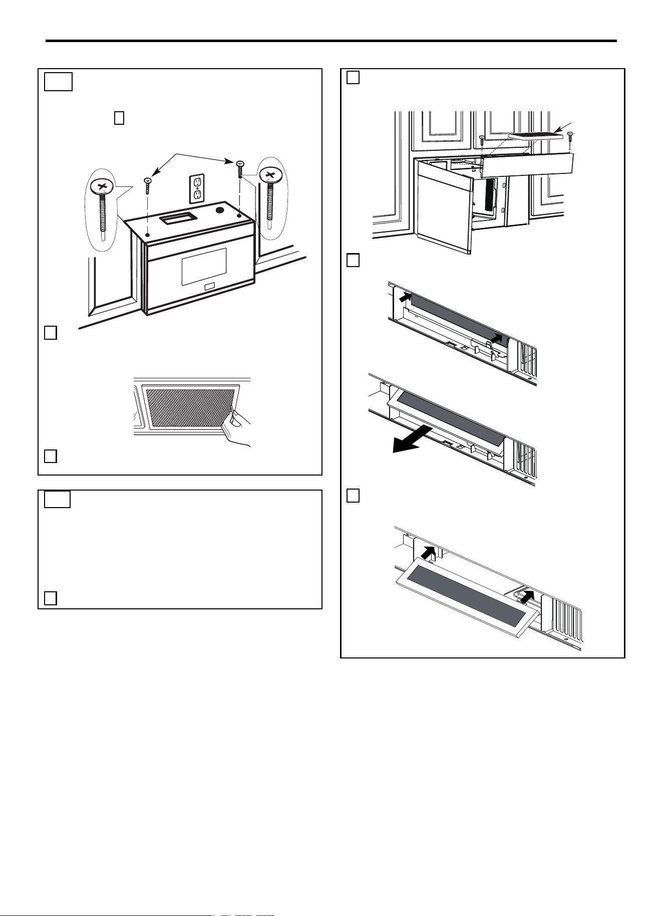
Installation Instruction
EN-42
C4. MOUNT THE MICROWAVE OVEN
(cont.)
5 Insert 2 self-aligning screws through outer
top cabinet holes. Turn two full turns on each
screw.
6 Tighten the outer two screws to the top of the microwave oven.
(While tightening screws, hold the microwave oven in place
against the wall and the top cabinet.)
7 Install grease filters. See the Use and Care packed with the
microwave.
2 Open the microwave door and remove the two vent mounting
screws located on top of the microwave using a #1 Phillips
screwdriver.
3 Remove the charcoal filter by pushing the top of the filter
inwards, then pull it forward out from the unit.
4 Slide the top of the new charcoal filter into the top of the filter
cavity.
C5. INSTALLING OR CHANGE THE
CHARCOAL FILTER (Some Models)
NOTE: The charcoal filter is factory installed in some models.
Refer to the Use and Care to see if yours is factory installed and for
replacement information.
For models without the recirculation filter access door,follow these
steps to replace or install a charcoal filter.
1 Unplug microwave oven or disconnect power.
Charcoal
Filte
r
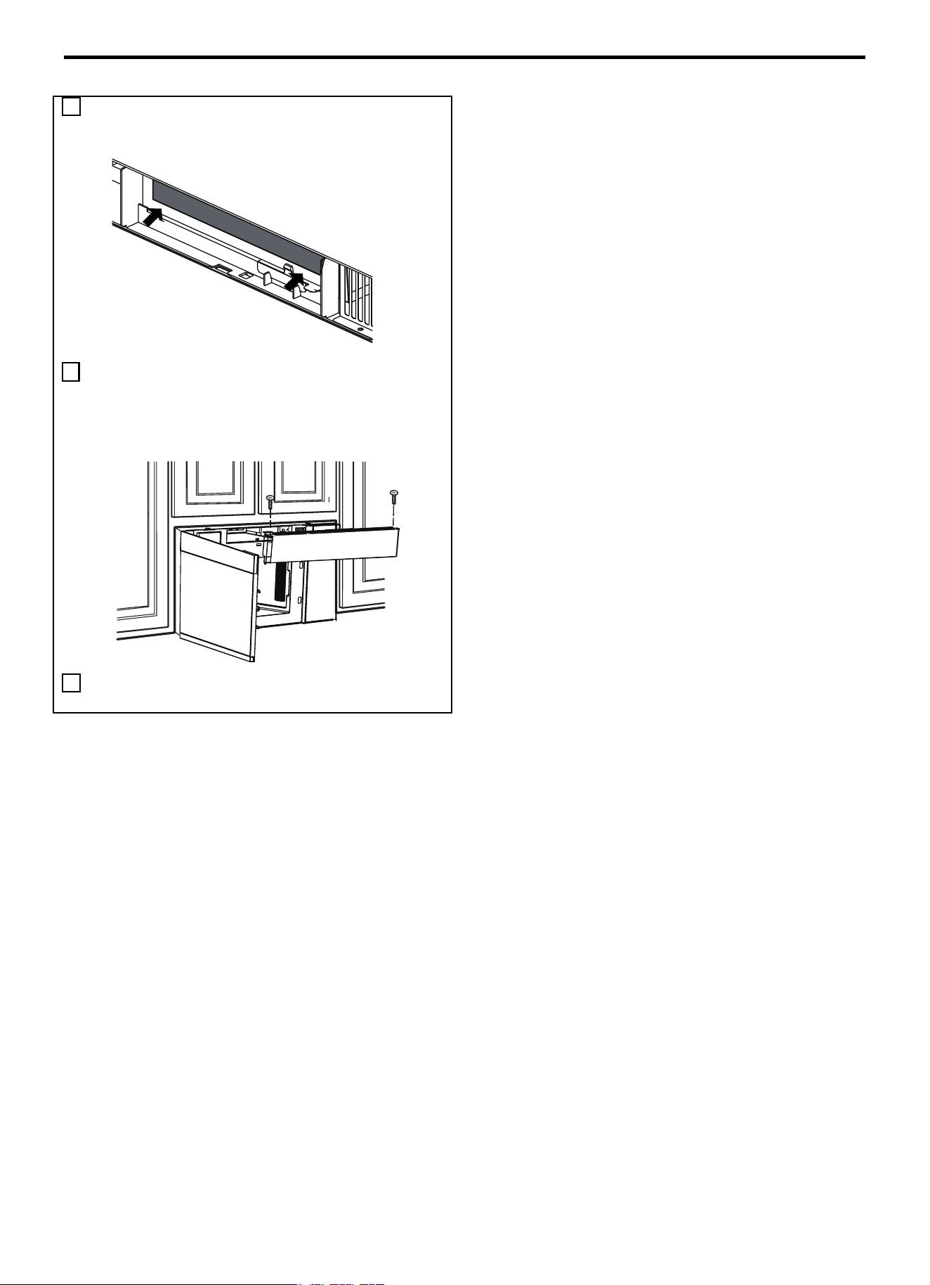
Installation Instruction
EN-43
5
Press the bottom of charcoal filter to place it into the correct
position.
6 Reinstall the vent by sliding the bottom of the vent into place.
Push the vent top into position and slide right into place.
Replace the two vent mounting screws located on top of the
microwave using a #1 Phillips screwdriver.
7 Close the microwave door. Plug in microwave oven or
reconnect power.
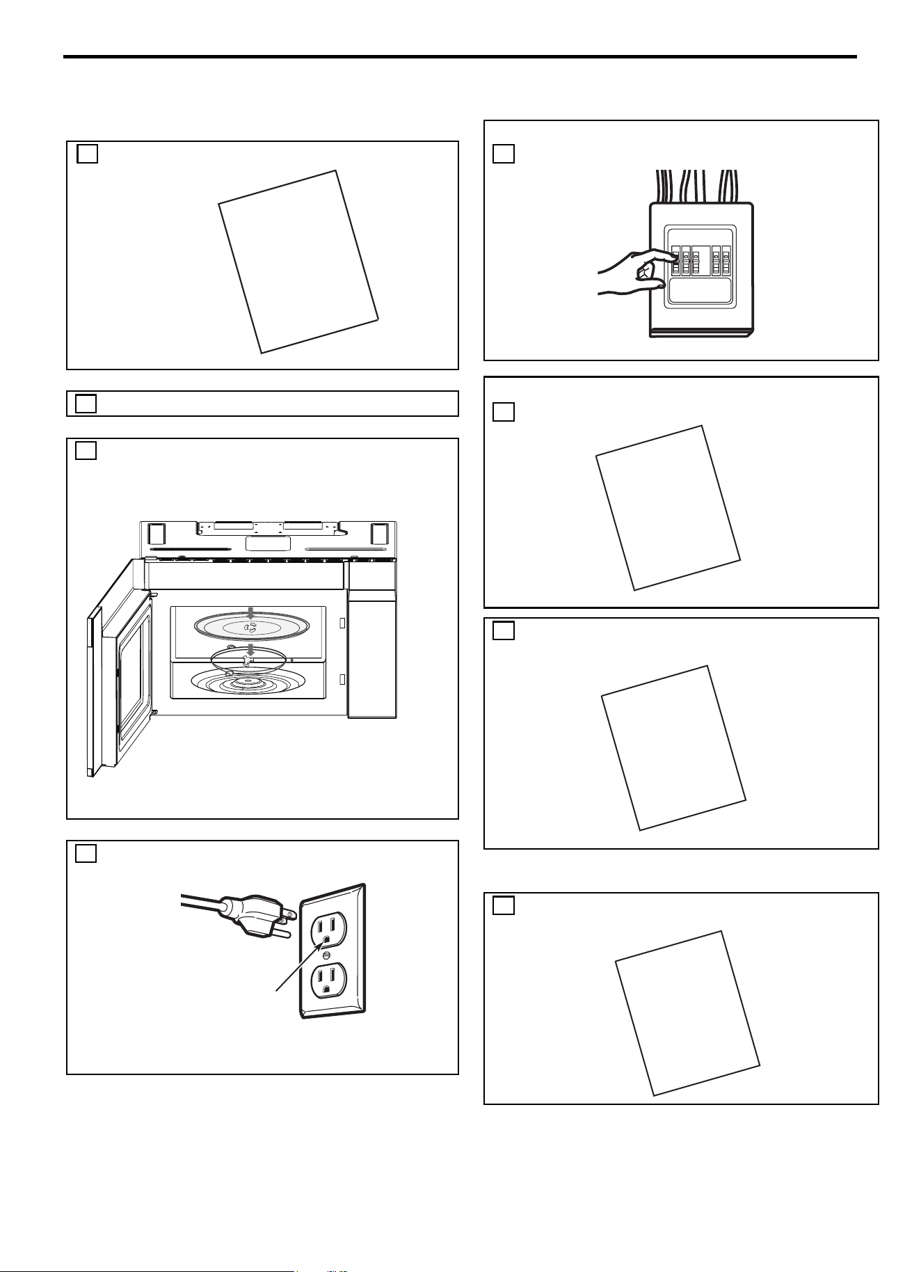
Installation Instruction
EN-44
BEFORE YOU USE YOUR MICROWAVE
1. Make sure the microwave oven has been installed according
to instructions.
5. Replace house fuse or turn breaker back on.
6. Read the USE & CARE Manual.
2. Remove all packing material from the microwave oven.
3. Install turntable ring and glas s tray in cavity.
7. KEEP INSTALLATION INSTRUCTIONS FOR THE
LOCAL INSPECTOR’S USE.
4. Plug power cord into a seperate and dedicated 15- to 20-amp
electrical outlet.
8. FILL OUT PRODUCT REGISTRATION CARD
AN SEND IN.
Ensure proper
ground exist
before use
INSTALLATION
INSTRUCTIONS
MANUAL
USE
|++&=
CARE
&
INSTALLATION
INSTRUCTIONS
PRODUCT
CARD
REGISTRATION

CUSTOMER CARE
For any warranty information and service request, contact us:
In USA: https://us.bertazzoni.com/more/support
In Canada: https://ca.bertazzoni.com/more/support


DU BUREAU DE NOTRE PRÉSIDENT
Cher nouveau propriétaire d’un appareil Bertazzoni,
Je tiens à vous remercier d’avoir choisi l’un de nos beaux produits pour votre maison.
Ma famille a commencé à fabriquer des appareils électroménagers en Italie en 1882,
bâtissant une réputation de qualité d’ingénierie et de passion pour la bonne cuisine.
Aujourd’hui, nos produits se distinguent par leur mélange unique de design italien
authentique et de technologie d’électroménager supérieure. Notre mission est de
fabriquer des produits qui fonctionnent parfaitement et qui apportent de la joie à leurs
propriétaires.
En fabriquant de beaux produits, nous répondons au goût de nos clients pour un joli
design. En les rendant polyvalents et faciles à utiliser, cuisiner avec Bertazzoni
devient un réel plaisir.
Ce manuel vous aidera à apprendre à utiliser et à entretenir votre appareil
Bertazzoni de la manière la plus sûre et la plus efficace, afin qu’il puisse vous donner
la plus grande satisfaction pour les années à venir.
Profitez !
Paolo Bertazzoni
Président
FR-
49


Four à micro-ondes
MODE D’EMPLOI
Modèle : KOTR24XV
Lisez attentivement ce mode d’emploi avant d’utiliser votre four à micro-ondes et
conservez-le soigneusement.
Si vous suivez les instructions qu’il contient, votre four vous fournira de nombreuses
années de bon service.
CONSERVER SOIGNEUSEMENT CE MODE D’EMPLOI

PRÉCAUTIONS CONTRE LE RISQUE D’EXPOSITION EXCESSIVE À L’ÉNERGIE DES
MICRO-ONDES
(a) Ne pas tenter de faire fonctionner le four avec la porte ouverte, car cela peut entraîner une exposition nocive à l’énergie des
micro-ondes.
Il est important de ne pas forcer ni d’altérer les verrouillages de sécurité.
(b) Ne placer aucun objet entre la face avant du four et la porte et veiller à éliminer toutes les salissures ou résidus de produit
nettoyant sur les surfaces d’étanchéité.
(c) Ne pas utiliser le four s’il est endommagé. Il est particulièrement important que la porte du four se ferme correctement et qu’il
n’y ait pas de dommages aux éléments suivants :
(1) PORTE (pliée)
(2) CHARNIÈRES ET LOQUETS (cassés ou desserrés)
(3) JOINTS DE PORTE ET SURFACES D’ÉTANCHÉITÉ
(d) Le four doit être réglé ou réparé uniquement par un technicien d’entretien dûment qualifié.
Spécifications
Modèle
KOTR24XV
Tension nominale
120 VAC,60 Hz
Entrée micro
-ondes
1500 W
Sortie
micro-ondes
1000 W
FR-52

INSTRUCTIONS DE SÉCURITÉ IMPORTANTES
Lors de l’utilisation d’appareils électriques, il convient d’observer les précautions de sécurité de base, à savoir :
AVERTISSEMENT - Pour réduire le risque de brûlures, de chocs électriques, d’incendie, de blessures corporelles ou d’exposition
excessive à l’énergie des micro-ondes :
1. Lire toutes les instructions avant d’utiliser l’appareil.
2. Lire et suivre les recommandations fournies au paragraphe : « PRÉCAUTIONS CONTRE LE RISQUE D’EXPOSITION
EXCESSIVE À L’ÉNERGIE DES MICRO-ONDES » en page 2 du présent mode d’emploi.
3. Cet appareil doit être relié à la terre. Brancher l’appareil uniquement à une prise correctement reliée à la terre. Voir le chapitre
« INSTRUCTIONS POUR LA MISE À LA TERRE » à la page 4.
4. Installer cet appareil en se conformant scrupuleusement aux instructions d’installation fournies.
5. Certains produits tels que les œufs entiers et les récipients scellés - par exemple, les bocaux en verre fermés - peuvent
exploser et ne doivent pas être chauffés dans ce four.
6. Utiliser cet appareil uniquement pour l’usage auquel il est destiné, tel que décrit dans le manuel. Ne pas utiliser de produits
chimiques ou de vapeurs corrosifs dans cet appareil. Ce type de four est spécialement conçu pour chauffer, cuire ou sécher
des aliments. Il n’est pas conçu pour un usage industriel ou de laboratoire.
7.
8. Ne pas utiliser cet appareil si le cordon ou la fiche sont abîmés, s’il ne fonctionne pas correctement ou s’il a été endommagé
ou est tombé.
9. L’entretien de cet appareil est du ressort exclusif d’un technicien qualifié. Contacter le revendeur agréé le plus proche pour
vérifier, réparer ou régler l’appareil.
10. Ne pas couvrir ou obstruer les ouvertures présentes sur l’appareil.
11. Ne pas ranger l’appareil à l’extérieur. Ne pas utiliser ce produit près de l’eau - par exemple, près d’un évier de cuisine, dans un
sous-sol humide, près d’une piscine ou d’un endroit similaire.
12. Ne pas immerger le cordon ou la fiche dans l’eau.
13. Tenir le cordon éloigné de la surface chauffée.
14. Éviter de laisser pendre le cordon par-dessus le bord de la table ou du plan de travail.
15. Pour le nettoyage des surfaces de la porte et du four entrant en contact lors de la fermeture de la porte, utiliser uniquement
des détergents doux et non abrasifs, ou appliquer le détergent à l’aide d’une éponge ou d’un chiffon doux.
16. Pour réduire le risque d’incendie dans la cavité du four :
1). Éviter de laisser cuire les aliments trop longtemps. Surveiller l’appareil lorsque du papier, du plastique ou d’autres matières
combustibles sont placés à l’intérieur du four pour faciliter la cuisson.
2). Retirer les attaches métalliques du sac en papier ou en plastique avant de le placer dans le four.
3). Si du matériel à l’intérieur du four s’enflamme, garder la porte du four fermée, éteindre le four et débrancher le cordon
d’alimentation ou couper l’alimentation au niveau du fusible ou du panneau de disjoncteur.
4). Ne pas utiliser la cavité du four à des fins de stockage. Ne pas laisser dans le four des matériaux en papier, des ustensiles
de cuisine ou des aliments lorsque le four n’est pas utilisé.
17. Les liquides, tels que l’eau, le café ou le thé, peuvent être surchauffés au-delà du point d’ébullition sans qu’une ébullition soit
visible. Les bulles indiquant que le liquide est en ébullition peuvent ne pas apparaître lorsque le récipient est retiré du four à
micro-ondes.
L’ÉBULLITION SOUDAINE D’UN LIQUIDE TRÈS CHAUD POURRAIT SE PRODUIRE LORSQUE LE RÉCIPIENT EST
SECOUÉ OU QU’UN USTENSILE EST INSÉRÉ DANS LE LIQUIDE.
Pour réduire le risque de blessures corporelles :
1) Ne pas surchauffer le liquide.
2) Remuer le liquide avant de le chauffer et à la moitié du temps de chauffage.
3) Ne pas utiliser de récipients à bord droit et col étroit.
4) Après chauffage, laisser le récipient reposer dans le four à micro-ondes pendant une courte période avant de le retirer de
l’appareil.
5)
Insérer une cuillère ou tout autre ustensile dans le récipient avec prudence.
18. Nettoyer fréquemment les hottes de ventilation - La graisse ne doit pas s’accumuler sur la hotte ou le filtre.
19. Lors du flambage d’aliments sous la hotte, veiller à allumer le ventilateur.
20. Nettoyer le filtre de la hotte de ventilation en étant particulièrement prudent. Les agents de nettoyage corrosifs, tels que les
nettoyants pour four à base de soude, peuvent endommager le filtre.
21. Peut-être utilisé au-dessus des équipements de cuisson au gaz et électriques.
FR-53
LES CONTENUS CHAUD PEUVENT CAUSER DES BLESSURES
GRAVES. NE PAS AUTORISER LES ENFANTS À JOUER
AVEC
LE FOUR À MICRO-ONDES. Prendre des précautions lors
du retrait d'éléments chauds.

CONSERVER SOIGNEUSEMENT CES INSTRUCTIONS !
INSTRUCTIONS POUR LA MISE À LA TERRE
Cet appareil doit être relié à la terre. En cas de court-circuit électrique, la mise à la terre réduit le risque de choc électrique en
fournissant une déviation du courant électrique vers le sol. Cet appareil est équipé d’un cordon doté d’un fil de mise à la terre et
d’une fiche de mise à la terre. La fiche doit être branchée sur une prise correctement installée et mise à la terre.
AVERTISSEMENT - Une mauvaise utilisation de la mise à la terre peut entraîner un risque de choc électrique.
Consulter un électricien ou un technicien qualifié si les instructions de mise à la terre ne sont pas complètement comprises ou s’il
existe un doute quant à savoir si l’appareil est correctement mis à la terre. S’il est nécessaire d’utiliser une rallonge, utiliser
uniquement une rallonge à 3 fils munie d’une fiche de mise à la terre à 3 lames, et une prise à 3 emplacements qui accepte la fiche
sur l’appareil. La valeur nominale indiquée de la rallonge doit être égale ou supérieure à la puissance électrique de l’appareil.
DANGER - Risque de choc électrique
Toucher certains composants internes peut causer des blessures graves ou la mort. Ne pas démonter cet appareil.
AVERTISSEMENT - Risque de choc électrique
Une mauvaise utilisation de la mise à la terre peut entraîner un choc électrique. Ne pas brancher la fiche tant que l’appareil n’est
pas correctement installé et mis à la terre.
1. Un cordon d’alimentation court est fourni pour réduire les risques d’emmêlement ou de trébuchement sur un cordon plus long.
2. Des ensembles de cordons plus longs ou des rallonges sont disponibles et peuvent être utilisés si des précautions sont prises
lors de leur utilisation.
3. Si un long cordon ou une rallonge est utilisé :
1) La puissance électrique indiquée sur le cordon ou la rallonge doit être au moins aussi élevée que la puissance électrique de
l’appareil.
2) La rallonge doit être un cordon de type mise à la terre à 3 fils.
3) Le cordon le plus long doit être disposé sur le plan de travail de manière à éviter que des enfants tirent dessus ou
trébuchent involontairement sur celui-ci.
FR-54

USTENSILES
MISE EN GARDE - Risque de blessures corporelles
Des ustensiles hermétiques pourraient exploser. Les récipients fermés doivent être ouverts et les sachets en plastique doivent être
percés avant la cuisson.
Voir les instructions relatives aux « Matériaux pouvant être utilises dans un four à micro-ondes ou à éviter dans un four à micro-
ondes ».
Il peut y avoir des ustensiles non métalliques qu’il vaut mieux ne pas utiliser dans un four à micro-ondes. En cas de doute, il est
possible de tester l’ustensile en question en suivant la procédure ci-dessous.
Pour tester l’ustensile :
1. Remplir un récipient allant au micro-ondes avec 1 tasse d’eau froide (250 ml) avec l’ustensile en question.
2. Cuire à la puissance maximale pendant 1 minute.
3. Toucher délicatement l’ustensile. Si l’ustensile vide est chaud, ne pas l’utiliser pour la cuisson au micro-ondes.
4. Ne pas dépasser 1 minute de cuisson.
FR-55
Ce produit a été testé et jugé conforme aux limites du four à
micro-ondes, conformément à la section 18 de la
réglementation FCC.
Ce produit peut émettre de l’énergie
radio-fréquence, ce qui pourrait causer des interférences à
des produits tels que radio,
télévision, moniteur pour bébé,
téléphone sans fil, Bluetooth, routeur sans fil, etc., ce qui
peut être confirmé en éteignant et en
rallumant ce produit.
S’il est présent, l’utilisateur est invité à tenter de corriger en
prenant une ou plusieurs des contre
-mesures suivantes :
(1) Augmenter la distance d’espacement entre le four à
micro-ondes et tout autre produit recevant
l’interférence.
(2) Si possible, utiliser une antenne réceptrice correctement
installée et/ou réorienter l
’
antenne de réception de
l’autre produit qui reçoit l’interférence.
(3)
Brancher le four à micro
-
ondes dans une prise différente
de celle de l’autre produit qui reçoit l’interférence.
(4) Nettoyer la porte et les surfaces d’étanchéité du four.
(Voir le chapitre Entretien et nettoyage du four à
micro-ondes)
INTERFÉRENCES RADIO

Matériaux adaptés pour la cuisson au micro-ondes
Ustensiles
Remarques
Plat brunisseur
Suivre les instructions du fabricant*. La base du plat brunisseur doit être
d’au moins 3/16 po (5 mm) au-dessus de la plaque tournante. Une
utilisation incorrecte peut provoquer la rupture du plateau tournant.
Vaisselle
N’utiliser que des ustensiles allant au micro-ondes. Suivre les
instructions du fabricant. Ne pas utiliser de vaisselle fêlée ou ébréchée.
Bocaux en verre
Toujours retirer le couvercle. Utiliser uniquement pour chauffer les
aliments jusqu’à ce qu’ils soient juste tièdes. La plupart des bocaux en
verre ne sont pas résistants à la chaleur et peuvent se briser.
Verrerie
N’utiliser que des objets en verre qui résistent à la chaleur du four.
S’assurer de l’absence de toute garniture métallique. Ne pas utiliser de
vaisselle fêlée ou ébréchée.
Poches de
cuisson au four
Suivre les instructions du fabricant*. Ne pas fermer avec une attache
métallique. Pratiquer des fentes pour permettre à la vapeur de
s’échapper.
Assiettes et
tasses en carton
À utiliser uniquement pour cuire ou réchauffer brièvement. Ne jamais
laisser le four sans surveillance quand il est en cours d’utilisation.
Serviettes en
papier
À utiliser pour couvrir les aliments qui sont réchauffés et absorber la
graisse. À utiliser sous surveillance uniquement pour un cuisson courte
Papier sulfurisé
À utiliser pour couvrir, afin d’éviter les éclaboussures ou pour envelopper
un produit cuit à la vapeur.
Plastique
N’utiliser que des ustensiles allant au micro-ondes. Suivre les
instructions du fabricant*. Ne l’utiliser que s’il est étiqueté « Va au
micro-ondes ». Certains récipients e
n plastique se ramollissent au fur et
à mesure que les aliments qu’ils contiennent chauffent. Les « sachets
de cuisson » et les sachets en plastique scellés doivent être fendus,
percés ou aérés, tel qu’indiqué sur l’emballage.
Emballage
plastique
N’utiliser que des ustensiles allant au micro-ondes. Utiliser pour couvrir
les aliments pendant la cuisson pour retenir l’humidité. L’emballage en
plastique ne doit pas être au contact des aliment.
Thermomètres
N’utiliser que s’il est considéré comme sécuritaire pour l’utilisation au
micro-ondes (p. ex. les thermomètres à viande et à sirop).
Papier paraffiné
À utiliser pour couvrir, afin d’éviter les éclaboussures ou pour retenir
l’humidité.
FR-56

Matériaux adaptés pour la cuisson au micro-ondes
Ustensiles
Remarques
Plateau en
aluminium
Peut être source d’étincelles. Utiliser un plat pouvant aller au micro-
ondes à la place,
Boîte en carton
pour produits
alimentaires
avec poignée en
métal
Peut être source d’étincelles. Utiliser un plat pouvant aller au micro-
ondes à la place,
Métal ou
ustensiles à
rebords
métalliques
Les métaux isolent les aliments de l’énergie micro-ondes. La bordure de
métal peut être source d’étincelles.
Attaches
métalliques
Peut être source d’étincelles et provoquer un incendie dans le four..
Sachets en
papier
Les sachets en papier peuvent provoquer un incendie dans le four
Mousse
plastique
La mousse plastique peut fondre ou contaminer le liquide à l’intérieur
quand elle est exposée à des températures élevées.
Bois
Le bois sèche quand il est utilisé dans le four à micro-ondes et peut se
fractionner ou se fissurer.
FR-57
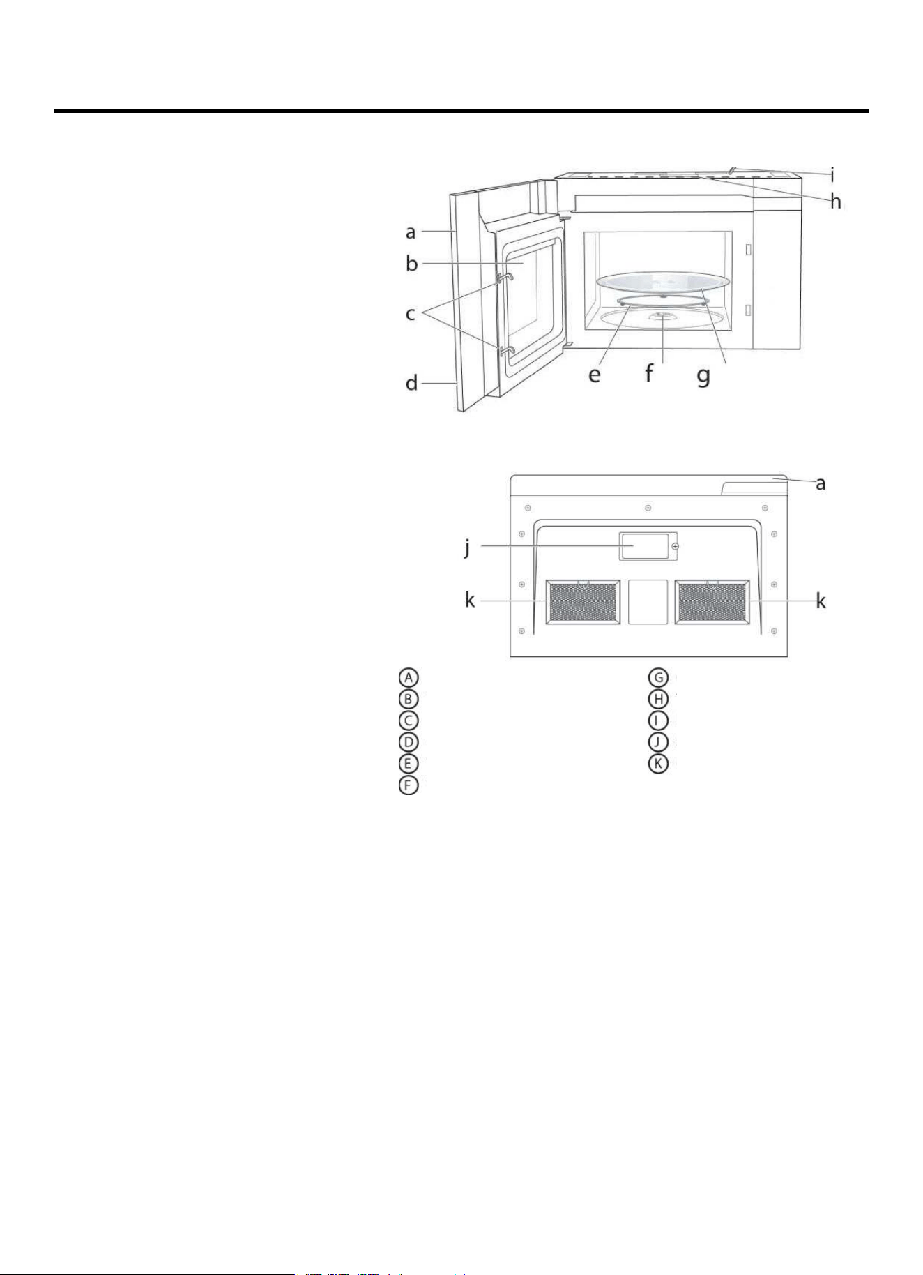
INSTRUCTIONS D’UTILISATION
CARACTÉRISTIQUES DU FOUR À MICRO-ONDES
Vue avant
Vue du dessous
Porte
Fenêtre d
’observation
Système de verrouillage de sécurité
Panneau de commande
Anneau pour plateau rotatif
Axe pour plateau rotatif
Plateau rotatif en verre
Grille supérieure
Cordon d
’alimentation
Lampes de surface
Filtres à graisses
FR-58
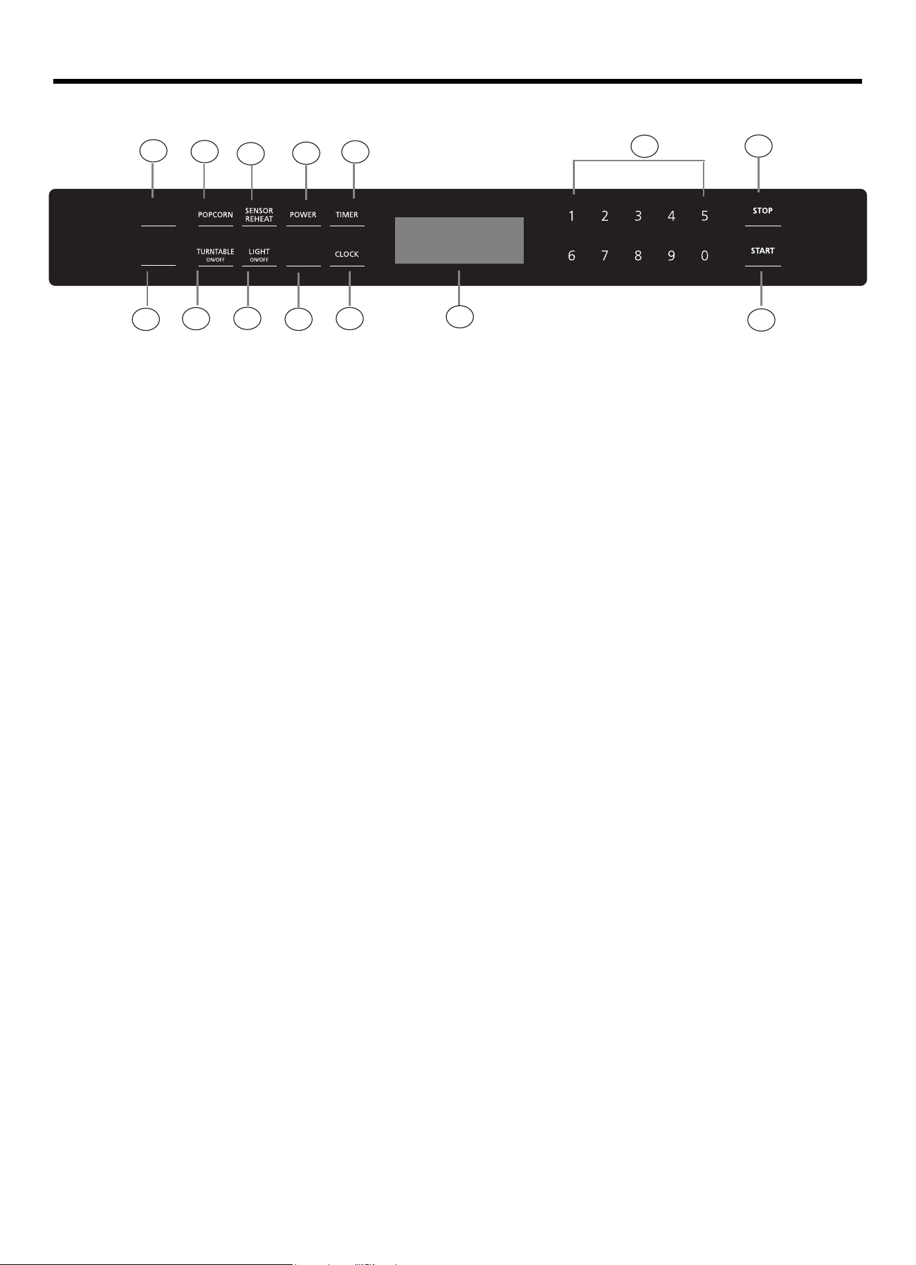
COMMANDES
1) Cuisson par capteur
2) Popcorn
3) Réchauffage par capteur
4) Puissance
5) Minuteur
6)
7) Plateau tournant Marche/Arrêt
8) Éclairage Marche/Arrêt
9) Vitesse de ventilation
10) Horloge
11) Pavé numérique
12) Arrêter/Réinitialiser
13) Start/+ 30Sec.
14) Écran d’affichage
FR-59
1
3
4
8
7
10
2
6
5
14
13
12
11
9
AUTO
DEFROST
SENSOR
COOK
VENT SPEED
RESET
+30 SEC
Décongélation automatique

Fonctionnement
1. Niveau de puissance
11 niveaux de puissance sont disponibles.
Niveau
10
9
8
7
6
5
4
3
2
1
0
Puissance
100 %
90 %
80 %
70 %
60 %
50 %
40 %
30 %
20 %
10 %
0 %
Afficheur
PL-HI
PL-90
PL-80
PL-70
PL-60
PL-50
PL-40
PL-30
PL-20
PL-10
PL-0
2. Mise sous tension
Lorsque le four à micro-ondes est mis sous tension, l’écran affiche « 12:00 » « PRESS CLOCK ENTERTIME ».
L’avertisseur sonore retentira une fois. Appuyer sur les touches numériques pour régler l’horloge ou appuyer sur «
STOP/RESET » pour quitter le mode de réglage de l’horloge. S’il n’y a pas d’opération dans les 5 minutes, le four entrera
en état d’attente.
3. Horloge
L’horloge peut être réglée en mode 12 heures.
1) En état d’attente, appuyer une fois sur « Clock ». L’écran affichera « 12:00 PRESS CLOCK ENTER TIME ».
2) Appuyer sur les touches numériques et entrer l’heure correcte. Par exemple, l’heure actuelle est 10:12, dans ce cas appuyer
tour à tour sur « 1,0,1, 2 ».
3) Appuyer sur le bouton « Start/+30 Sec » pour confirmer l’heure de l’horloge.
4. Minuteur
1) Appuyer une fois sur « , « ENTER TIME » clignotera à l’afficheur. »
2) Appuyer sur les touches numériques et saisir le temps du minuteur. (La valeur maximale est de 99:99).
3) Appuyer sur « Start/+30 Sec » pour confirmer le réglage. Le minuteur démarre le compte à recours.
FR-60
Timer

5. Temps de cuisson
1) En mode d’attente, appuyer sur les touches numériques pour régler le temps de cuisson. (La valeur maximale est de 99:99).
2) Appuyer plusieurs fois sur «
pour régler le niveau de puissance. Le niveau de puissance par défaut est PL-HI.
»
3) Appuyer sur «
Start/+30Sec » pour démarrer la cuisson au micro-ondes.
6. Fonction de verrouillage de sécurité des enfants
Utiliser cette fonction pour empêcher les enfants d’allumer accidentellement le four.
Pour activer le verrouillage :
En état d’attente, appuyer sur « STOP/RESET » et maintenir la touche enfoncée pendant trois secondes. Un long bip retentit et l’icône
d’un verrou s’affiche.
Pour désactiver le verrouillage :
En état verrouillé, appuyer sur « STOP/RESET » et maintenir la touche enfoncée pendant trois secondes. Un long bip retentit.
7. Cuisson rapide
(1) En état d’attente, la cuisson instantanée au niveau de puissance 100 % peut être démarrée en sélectionnant un temps de cuisson
de 1 à 9 minutes en appuyant sur les pavés numériques 1 à 9.
(2) En état d’attente, la cuisson instantanée au niveau de puissance 100 % avec un temps de cuisson de 30 secondes peut être
démarrée en appuyant sur « Start / + 30 Sec ». Chaque pression sur le même bouton augmentera le temps de cuisson de 30
secondes. Le temps de cuisson maximum est de 99 minutes et 99 secondes.
FR-61
Power

8. Popcorn
1) Appuyer plusieurs fois sur la touche « Popcorn » jusqu’à ce que la quantité souhaitée s’affiche.
« 1 » SET: correspond approximativement à 3,2 onces
« 2 » SET: correspond approximativement à 1,75 onces
Par exemple, appuyer une fois sur la touche « Popcorn », « 3.2 » s’affiche à l’écran.
2) Appuyer sur « START/+30SEC » pour démarrer la cuisson.
9. Décongélation automatique
1) Appuyer une fois sur « », l’écran affichera « MEAT ».Auto Defrost
2) Appuyer plusieurs fois sur «
« FISH » ou « BREAD » s’affichent tour à tour à l’écran.
Auto Defrost
3) Appuyer sur «
START/+30SEC » pour confirmer la fonction. L’écran affiche « ENTER WEIGHT » (saisir le poids).
4) Appuyer sur les touches numériques pour saisir le poids de l’aliment.
5) Appuyer sur «
START/+30SEC » pour démarrer la décongélation.
Programmes de décongélation automatique
Appuyer sur la
touche
Aliment
Plage de poids
1
Viande
0,1 - 6,0 livres
2
Volaille
0,1 - 6,0 livres
3
Poisson
0,1 - 6,0 livres
4
Pain
0,1 - 6,0 livres
FR-62
» pour sélectionner la fonction souhaitée. Ensuite, « MEAT », « POULTRY »,

10. Réchauffage par capteur
1) Appuyer une fois sur la touche « Sensor Reheat », l’écran affichera « BEVERAGE » .
2)
Appuyer plusieurs fois sur la touche « Sensor Reheat » jusqu’à ce que le menu souhaité s’affiche.
4)
Appuyer sur « START/+30SEC » pour démarrer le mode de cuisson par capteur. L’appareil démarre le processus de détection.
Le micro-ondes fonctionne pendant le processus de détection. Dès que le processus de détection est terminé, des bips retentissent et
le compte à rebours du temps de cuisson calculé démarre.
Remarque : Ne pas ouvrir la porte du four pendant le processus de détection sous peine d’annuler le programme.
Programmes de réchauffage par capteur
Programme no
Menu
Quantité
1
Boisson
1 - 3 tasses
2
Assiette
1 assiette
3
Pizza
1 - 4 tranches
4
Soupe/Sauce
1-3 tasses
5
Ragoût/Lasagne
10,5 onces
FR-63
Appuyez sur la touche "1-3" pour définir le poids de la nourriture.
(pour les menus "assiette,Pizza, Casserole", veuillez sauter cette étape.)
3)
Appuyer sur « START/+30SEC »
5)

11. Cuisson par capteur
1) Appuyer une fois sur la touche « Sensor Cook», l’écran affichera « POTATO ».
2)
Appuyer plusieurs fois sur « Sensor Cook » jusqu’à ce que le menu souhaité s’affiche.
3) Appuyer sur « START/+30SEC » pour démarrer le mode de cuisson par capteur. L’appareil démarre le processus de détection. Le
micro-ondes fonctionne pendant le processus de détection. Dès que le processus de détection est terminé, des bips retentissent et le
compte à rebours du temps de cuisson calculé démarre.
Remarque : Ne pas ouvrir la porte du four pendant le processus de détection sous peine d’annuler le programme.
Programmes de cuisson par capteur
Programme no
Menu
Quantité
1
Pomme de terre
1 - 4 pommes de terre
2
Légume frais
6/16 onces
3
Légume surgelé
8/16 onces
4
Plat cuisiné surgelé
10/20 onces
5
Riz
1 - 2 tasses
6
Petit déjeuner surgelé
8 - 12 onces
7
Viande
9-19 ondes
12. Cuisson à étapes multiples
Remarques : (1) Deux étapes de cuisson peuvent être réglées en mode de cuisson à étapes multiples.
(2) Si la fonction décongélation est sélectionnée, la première étape de cuisson démarrera automatiquement.
Exemple : Décongeler de la volaille d’un poids de 2 livres et la cuire à la puissance des micro-ondes de 80 % pendant 5 minutes.
(1) En état d’attente, appuyer sur les touches numériques pour régler un temps de cuisson des micro-ondes de 5 minutes.
(2) Appuyer plusieurs fois sur la touche « Power » pour régler le niveau de puissance PL-80.
(3) Appuyer deux fois sur « Auto Defrost », l’écran affichera «
Poultry ».
(4) Appuyer sur «
START/+30SEC » pour valider le menu.
(5) Appuyer sur les touches numériques pour régler le poids de 2 livres.
(6) Appuyer sur «
START/+30SEC » pour démarrer la cuisson.
13. Actionnement du ventilateur d’aération
1) Appuyer une fois sur la touche « » pour activer le ventilateur d’aération, l’écran affichera « HIGH ».
Le four retourne en mode d’attente après 2 secondes.
2) Appuyer deux fois sur «
Le four retourne en mode d’attente après 2 secondes.
», l’écran affichera « LOW ».
3) Appuyer deux fois sur «
» pour éteindre le ventilateur d’aération, l’écran affichera « OFF ». Le four retourne en
mode d’attente après 2 secondes.
FR-64
Vent
Vent
Vent Speed
Speed
Speed

15. Activation/Désactivation du plateau tournant
Pour de meilleurs résultats de cuisson, laisser le plateau tournant activé. Il peut être désactivé pour les grands plats.
Pour désactiver le plateau tournant, appuyer une fois sur « Turntable On/Off ».
L’écran affichera « OFF » pendant 2 secondes. Appuyer à nouveau sur « Turntable On/Off » pour activer le plateau
tournant. L’écran affichera « ON » pendant 2 secondes.
FR-65
14. Activation/Extinction de l’éclairage
L’appareil est équipé d’une lumière de surface de cuisson, pour éclairer la surface sous l’appareil. Il est possible de
définir deux niveaux de luminosité à l’aide de la touche « Light On/Off ».
Afficheur
Luminosité
HI
Forte
LO
Faible
OFF
Extinction
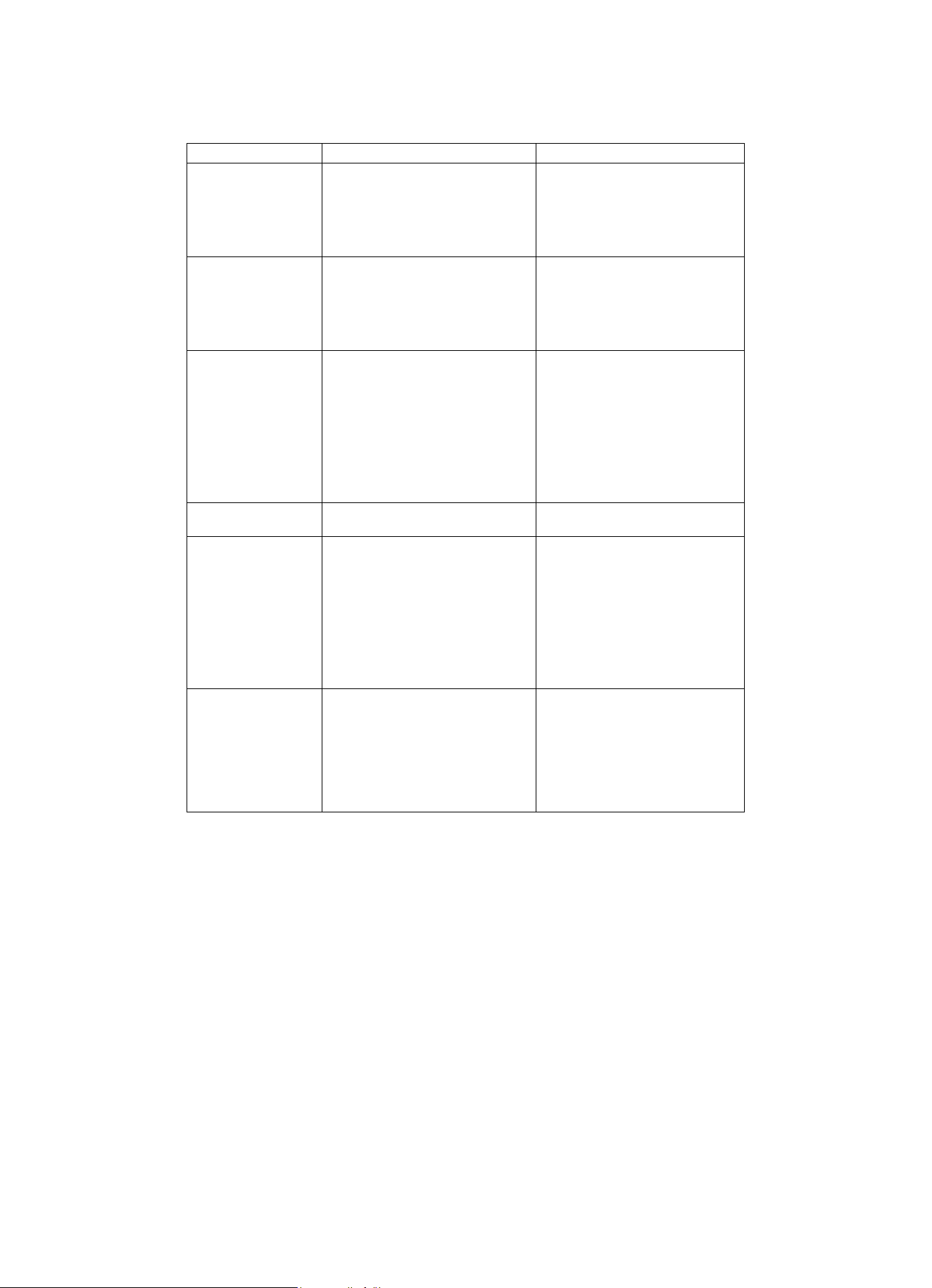
ENTRETIEN
Résolution des problèmes
Vérifier le problème en utilisant le tableau ci-dessous et essayer les solutions pour chaque problème. Si le four à micro-ondes ne
fonctionne toujours pas correctement, contacter le centre de service agréé le plus proche.
PROBLÈME
CAUSE POSSIBLE
SOLUTION POSSIBLE
Le four ne démarre
pas
a. La fiche du four n’est pas
branchée dans la prise
d’alimentation.
b. La porte est ouverte.
c. Le programme n’a pas été réglé
correctement.
a. Brancher la fiche dans la prise
secteur.
b. Fermer la porte et essayer à
nouveau.
c. Vérifier les instructions.
Arcs ou étincelles
a. Des matériaux à éviter dans le
four à micro-ondes ont été
utilisés.
b. Le four est utilisé à vide.
c. Des aliments ont été renversés
dans la cavité du four.
a. Utiliser uniquement des
ustensiles de cuisine allant au
micro-ondes.
b. Ne pas utiliser le four à vide.
c. Nettoyer la cavité avec une
serviette humide.
Aliments cuits de
manière non
homogène
a. Des matériaux à éviter dans le
four à micro-ondes ont été
utilisés.
b. Les aliments ne sont pas
complètement décongelés.
c. Le temps de cuisson et/ou le
niveau de puissance ne
conviennent pas.
d. Les aliments ne sont pas
retournés ou remués.
a. Utiliser uniquement des
ustensiles de cuisine allant au
micro-ondes.
b. Décongeler complètement les
aliments.
c. Utiliser un temps de cuisson et
un niveau de puissance corrects.
d. Retourner ou remuer les
aliments.
Aliments trop cuits
Le temps de cuisson et/ou le niveau
de puissance ne conviennent pas.
Utiliser un temps de cuisson et un
niveau de puissance corrects.
Aliments pas assez
cuits
a. Des matériaux à éviter dans le
four à micro-ondes ont été
utilisés.
b. Les aliments ne sont pas
complètement décongelés.
c. Les ouvertures de ventilation du
four sont obstruées.
d. Le temps de cuisson et/ou le
niveau de puissance ne
conviennent pas.
a. Utiliser uniquement des
ustensiles de cuisine allant au
micro-ondes.
b. Décongeler complètement les
aliments.
c. Vérifier que les ouvertures de
ventilation du four ne sont pas
obstruées.
d. Utiliser un temps de cuisson et
un niveau de puissance corrects.
Décongélation
incorrecte
a. Des matériaux à éviter dans le
four à micro-ondes ont été
utilisés.
b. Le temps de cuisson et/ou le
niveau de puissance ne
conviennent pas.
c. Les aliments ne sont pas
retournés ou remués.
a. Utiliser uniquement des
ustensiles de cuisine allant au
micro-ondes.
b. Utiliser un temps de cuisson et
un niveau de puissance corrects.
c. Retourner ou remuer les
aliments.
FR-66
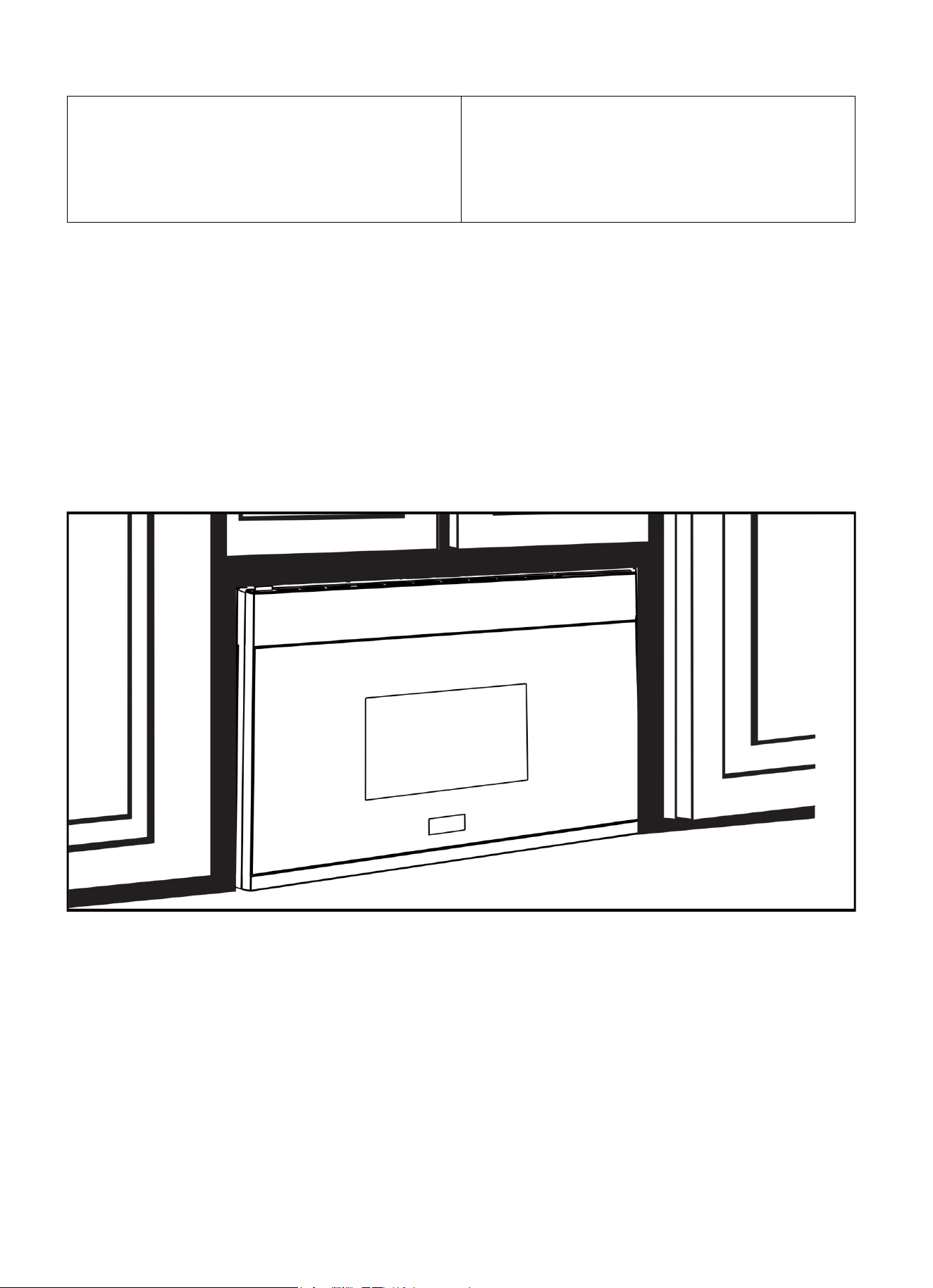
Instructions
d’installation
Four à micro-ondes à
hotte intégrée
AVANT DE PROCÉDER À L’INSTALLATION
Lire attentivement toutes les informations fournies ci-après.
• IMPORTANT — Conserver ce manuel pour
tout contrôle éventuel de l’inspecteur local.
• IMPORTANT — Respecter tous les codes
et règlements locaux.
• Remarques à l’intention de l’installateur —
Veiller à transmettre le présent manuel au consommateur.
Remarques à l’intention du consommateur —
Conserver le présent manuel pour toute consultation future.
Niveau de compétence - L’installation de cet appareil nécessite des
compétences mécaniques et électriques de base.
L’installateur est responsable de l’installation correcte de cet
appareil.
Toute défaillance du produit résultant d’une installation non
appropriée n’est pas couverte par la garantie.
LIRE SOIGNEUSEMENT.
CONSERVER CES INSTRUCTIONS.
Instructions d’installation
FR-68
SOMMAIRE
Informations générales
Consignes de sécurité importantes ...................................... 69
Exigences électriques ........................................................... 69
Dommages - Expédition/Installation ................................... 70
Pièces incluses ........................................................................ 70
Outillage requis .................................................................... 71
Espace de montage ............................................................... 71
Guide d’installation étape par étape
Installation de la plaque de montage ............................. 72-74
Dépose de la plaque de montage .................................. 72
Identification des montants muraux .............................. 72
Identification de l’emplacement de la plaque murale ... 73
Alignement de la plaque murale ................................... 74
Types d’installation .......................................................... 75-88
Hotte à évacuation ............................................................ 76-77
A Échappement haut vers l’extérieur ......................... 78-81
Fixer la plaque de montage à la paroi ..................... 78
Préparation du meuble haut .................................... 79
Réglage du ventilateur du micro-ondes
pour l’échappement haut vers l’extérieur ........ 79-80
Contrôle du bon fonctionnement de l’amortisseur 80
Montage du four à micro-ondes ..................... 80-81
Réglage de l’adaptateur d’échappement ............. 81
Raccordement des conduits .................................. 81
B Échappement arrière vers l’extérieur ....................... 82-85
Préparation de la paroi arrière pour
l’échappement arrière vers l’extérieur ................. 82
Dépose de la plaque du ventilateur ...................... 82
Fixer la plaque de montage à la paroi ................. 83
Préparation du meuble haut ................................ 83
Réglage du ventilateur du micro-ondes
pour l’échappement arrière vers l’extérieur ..... 83-84
Montage du four micro-ondes ............................... 85
C Recirculation de l’air ............................................... 86-88
Fixer la plaque de montage à la paroi .................... 86
Préparation du meuble haut ................................... 87
Contrôle de la plaque du ventilateur ..................... 87
Montage du four à micro-ondes ...................... 87-88
Installer ou remplacer le filtre à charbon .............. 88
Avant d’utiliser le four micro-ondes pour la première fois 90
Informations relatives au gabarit ......................................... 91
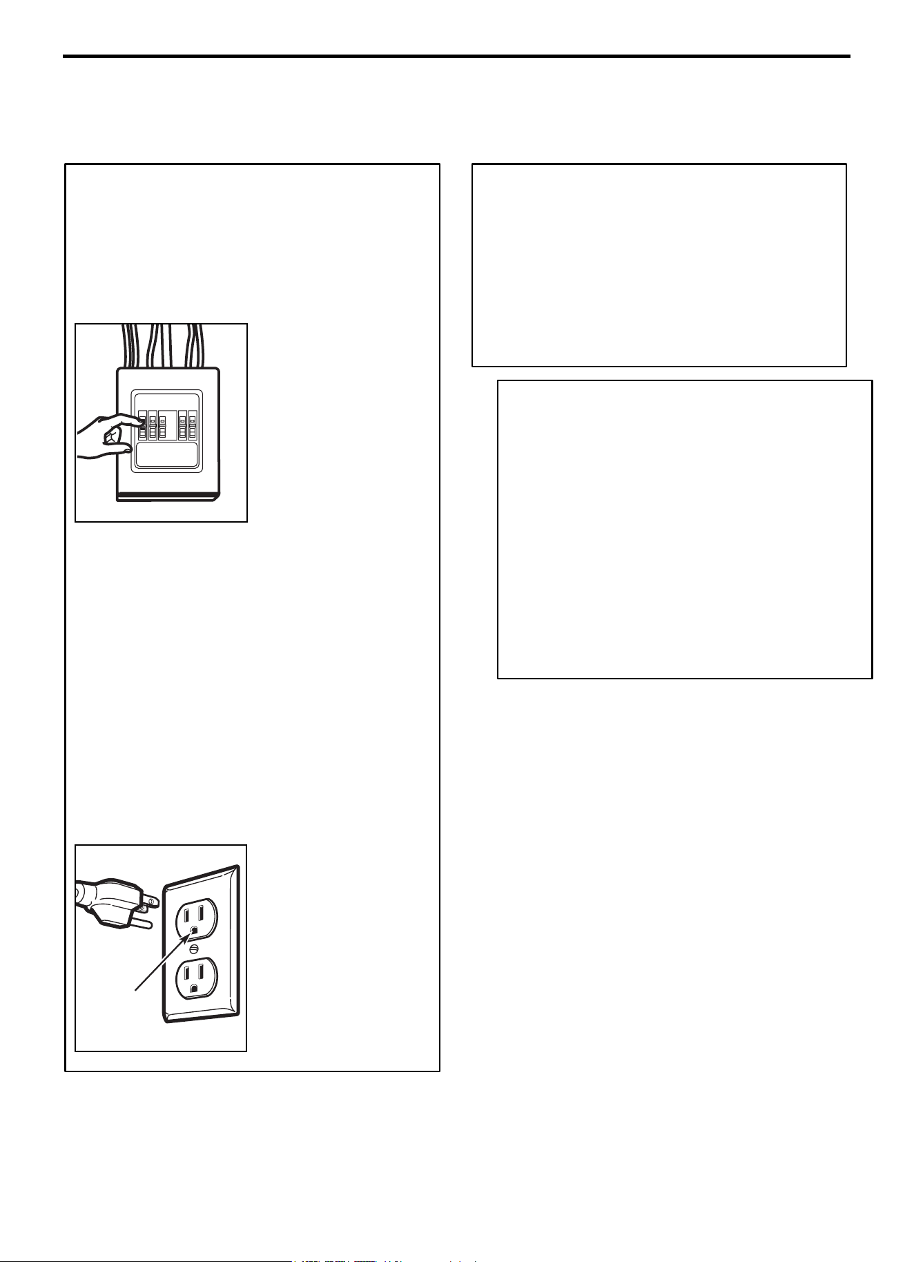
Instructions d’installation
FR-69
INSTRUCTIONS DE SÉCURITÉ IMPORTANTES
Ce produit nécessite une sortie de terre à trois broches.
L’installateur doit effectuer une vérification de la continuité de
la mise à la terre sur le boîtier de prise de courant avant de
commencer l’installation pour s’assurer que le boîtier de prise
de courant est correctement mis à la terre. Si tel n’est pas le
cas, ou si le boîtier de prise de courant ne satisfait pas aux
exigences électriques énumérées (sous EXIGENCES
ÉLECTRIQUES), faire appel à un électricien qualifié pour
corriger tout défaut.
MISE EN GARDE : Pour
la sécurité personnelle,
retirer le fusible de
l’
installation domestique ou
ouvrir le disjoncteur avant
de commencer
l’installation, afin d’éviter
des blessures graves ou la
mort suite à un choc
électrique.
MISE EN GARDE : Pour la sécurité personnelle, la surface
de montage doit pouvoir supporter la charge de l’armoire,
en plus du poids supplémentaire de ce produit de 63 à 85
livres (28,5 à 38,5 kg), plus des charges supplémentaires
allant jusqu’à 50 livres (22,7 kg) ou un poids total de 113 à
135 livres (51,3 à 61,2 kg).
MISE EN GARDE : Pour des raisons de sécurité
personnelle, ce produit ne peut pas être installé dans des
armoires disposées en îlot ou en péninsule. Il doit être
monté à la fois sur une armoire haute ET sur un mur.
REMARQUE : Pour faciliter l’installation et garantir la
sécurité personnelle, la présence de deux personnes est
recommandée pour installer le produit.
IMPORTANT - VEUILLEZ LIRE ATTENTIVEMENT.
POUR DES RAISONS DE SÉCURITÉ PERSONNELLE,
CET APPAREIL DOIT ÊTRE CORRECTEMENT MIS À
LA TERRE POUR ÉVITER UN CHOC GRAVE OU
MORTEL.
Le cordon d’alimentation
de cet appareil est équipé
d’une prise à trois broches
(mise à la terre) qui
s’accouple à une prise (de
mise à la terre) tripolaire
pour minimiser la
possibilité de risque de choc
électrique de cet appareil.
S’assurer qu’une
mise à la terre
conforme est
présente avant
toute utilisation.
Faire vérifier la prise murale et le circuit par un électricien
qualifié pour s’assurer que la prise est correctement mise à
la terre.
En présence d’une prise murale standard bipolaire, il est
très important qu’un électricien qualifié procède au
remplacement par une prise murale tripolaire
correctement mise à la terre.
NE PAS COUPER, NE PAS DÉFORMER NI RETIRER
L’UNE OU L’AUTRE BROCHE DU CORDON
D’ALIMENTATION. NE PAS UTILISER AVEC UNE
RALLONGE
EXIGENCES
ÉLECTRIQUES
La tension nominale du produit est de 120 VAC, 60 Hz,
15 ampères et 1,6 kilowatts. Ce produit doit être connecté à un
circuit d’alimentation séparé et dédié dont la tension et la
fréquence sont appropriées. La taille du fil doit être conforme
aux exigences du Code national de l’électricité ou du code
local en vigueur pour cette puissance nominale en kilowatts.
Le cordon d’alimentation et la fiche doivent être placés dans
une seule prise de terre séparée et dédiée de 15 à 20 ampères.
Le boîtier de prise de courant doit être situé dans l’armoire au-
dessus du four à micro-ondes. Le boîtier de prise de courant et
le circuit d’alimentation doivent être installés par un électricien
qualifié et conformes au Code national de l’électricité ou au
code local en vigueur.
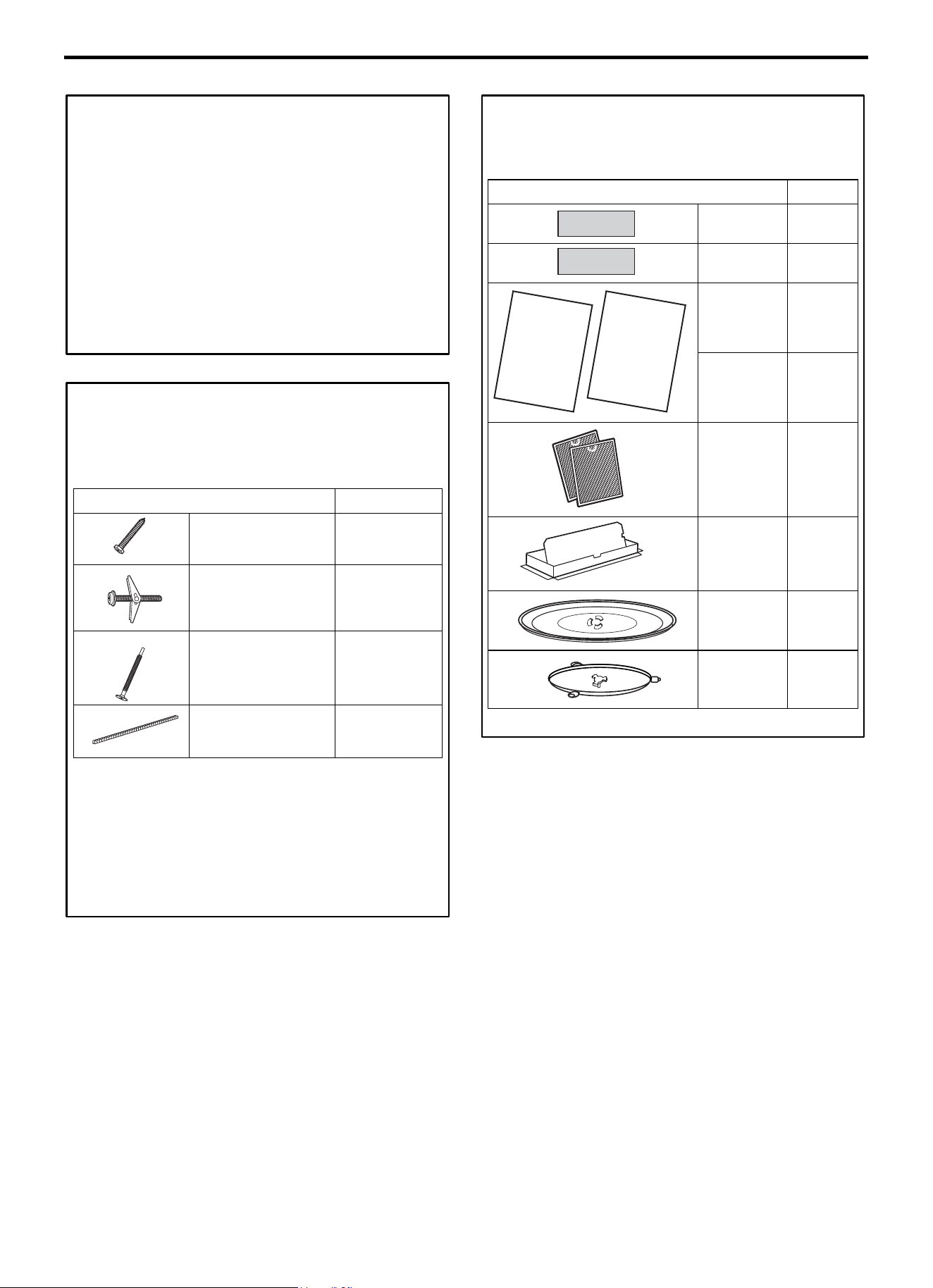
Instructions d’installation
FR-70
DOMMAGES—
EXPÉDITION/
INSTALLATION
• Si l’appareil est endommagé pendant l’expédition, le
retourner au magasin dans lequel il a été acheté pour
réparation ou remplacement.
• Si l’appareil est endommagé par le client, la réparation ou
le remplacement est à la charge du client.
• Si l’appareil est endommagé par l’installateur (s’il n’est
pas le client), la réparation ou le remplacement doit être
effectué selon accord entre le client et l’installateur.
PIÈCES INCLUSES
PAQUET MATÉRIEL
PIÈCE
QUANTITÉ
Vis à bois
(1/4” x 2”)
2
Boulons à ailettes
(et écrous papillon)
(3/16” x 3”)
2
Vis machine à auto-
alignement
(1/4”-28 x 31/4”)
3
Passe-câble en Nylon
(pour armoires
métalliques)
1
Le matériel à utiliser pour l’installation est emballé dans le
paquet accompagnant le produit. Vérifier que toutes les pièces
sont présentes.
REMARQUE : Des pièces supplémentaires sont incluses.
PIÈCES INCLUSES
(SUITE)
PIÈCES SUPPLÉMENTAIRES
PIÈCE
QUANTITÉ
Gabarit
meuble haut
1
Gabarit paroi
arrière
1
Instructions
d’installation
1
Manuel
d’utilisation et
d’entretien
1
Filtres à
graisses
emballés
séparément
2
Adaptateur
conduit
d’échappement
1
Plateau en
verre
1
Anneau de
roulement
1
INSTALLATION
INSTRUCTIONS
USE & CARE
MANUAL
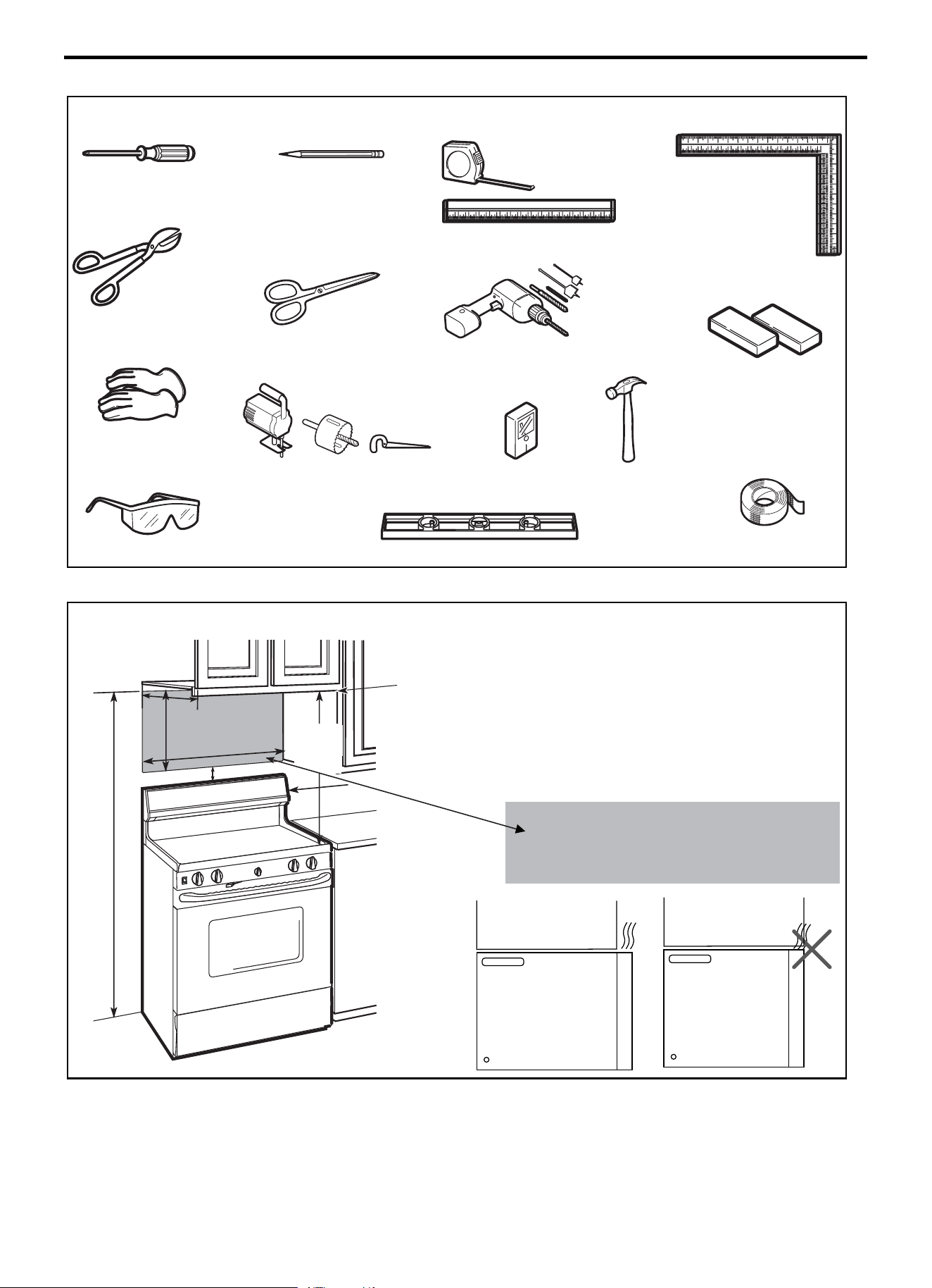
Instructions d’installation
FR-71
OUTILLAGE REQUIS
# 1 Tournevis cruciforme
Crayon
Cisailles (pour la découpe de
l’amortisseur, si nécessaire)
Ciseaux
(Pour la découpe du gabarit, si
nécessaire)
Perceuse électrique avec
mèches de 3/16’’ et de 5/8’’
Blocs de remplissage ou chutes
de bois, si nécessaire pour
l’espacement du meuble haut
(utilisés uniquement pour
l’installation d’armoires à fond en
retrait)
Gants
Scie (sauteuse, à tours ou à
guichet)
Détecteur de montants ou
marteau (en option)
Lunettes de sécurité
Niveau
Ruban ò conduit et à masquer
ESPACE DE MONTAGE
REMARQUES :
• L’espace entre les armoires doit avoir une largeur de
24 po (61,0 cm) et ne présenter aucune obstruction.
• Si le four à micro-ondes doit être ventilé vers
l’extérieur, consulter le chapitre Hotte à évacuation
pour la préparation des conduits d’évacuation.
• Si le four à micro-ondes est installé sous des armoires à
fond plat et lisse, suivre soigneusement les instructions
du gabarit meuble haut pour connaître l’espace requis
pour le passage du cordon d’alimentation.
• Pour obtenir des information sur le gabarit de montage,
se reporter à la page 24 (Instructions d’installation).
• Si la profondeur de l’armoire, y compris les portes de
l’armoire, est supérieure à 13 po, l’unité doit être
espacée du mur à l’aide de matériaux adéquats
supportant 150 livres (68 kg) pour permettre une
évacuation/admission d’air par le haut appropriée.
Armoire
Armoire
Mètre ruban et règle
Équerre de
charpentier
(en option)
La distance entre le
bord inférieur de
l’
armoire et la
surface de cuisson
doit être de 30 po
(76,2 cm).
66 po (167,6 cm)
ou plus du sol au
sommet du four
à micro
-ondes
Dosseret
2
“ (5.1 cm)
30
“
(76.2 cm)
min.
16
1
⁄
2
“
(41.9 cm)
24“
(61.0cm)
13’’ Maximum (33 cm)
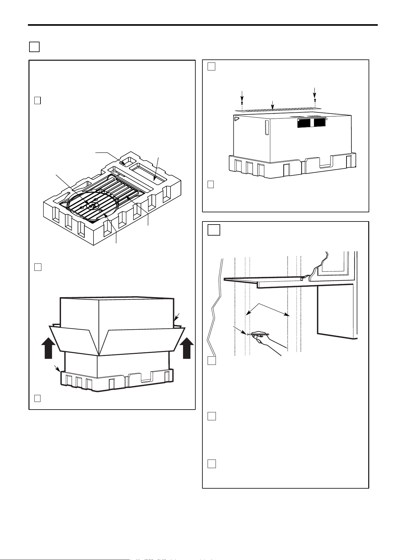
Instructions d’installation
FR-72
1 INSTALLATION DE LA PLAQUE DE MONTAGE
Armoire
A. RETRAIT DU FOUR À MICRO-
ONDES DU CARTON/RETRAIT
DE LA PLAQUE DE MONTAGE
1 Retirer les instructions d’installation, le manuel
d’utilisation et d’entretien, l’adaptateur d’échappement,
l’anneau de roulement, la grille, les filtres, le plateau en
verre et le petit sachet contenant le matériel. Ne pas
enlever la mousse de polystyrène qui protège l’avant du
four.
2 Replier complètement les 4 rabats du carton contre les
côtés du carton. Ensuite, retourner délicatement le four
avec le carton sur la partie supérieure du four. Le four doit
reposer dans la mousse de polystyrène.
3 Retirer le carton du four en le soulevant.
Petit sachet contenant le
matériel
Adaptateur
d’évacuation
Filtres et anneau de
roulement sous le plateau
Plateau en
verre
Grille
(sur
certains
modèles)
Carton
Mousse de
polystyrène
4 Couper le milieu du sac en plastique de protection
extérieur pour retirer la plaque de montage.
5
Déposer les vis de chaque extrémité de la plaque de
montage. Cette plaque sera utilisée comme gabarit de paroi
arrière et pour le montage. Réinstaller les vis
précédemment déposées dans leurs trous respectifs.
Vis
Vis
Plaque de montage
B. IDENTIFICATION DES
MONTANTS MURAUX
1 Identifier les montants à l’aide de l’une des
méthodes suivantes :
A. Détecteur de montants - un dispositif magnétique
qui localise les clous.
B. Utiliser un marteau pour tapoter légèrement sur la
surface de montage afin de trouver un son plein.
Celui-ci indiquera l’emplacement du montant.
2 Après avoir localisé le(s) montant(s), trouver le
centre en sondant le mur avec un petit clou pour
identifier les bords du montant. Marquer ensuite le
milieu du montant, entre les deux bords. Le centre
de tout montant adjacent doit être situé à 16’’
(40,6 cm) ou 24’’ (61 cm) de ce repère.
3 Tracer une ligne au centre des montants.
LE FOUR À MICRO-ONDES DOIT ÊTRE ATTACHÉ À AU MOINS UN
MONTANT MURAL.
Milieu
Montants
muraux
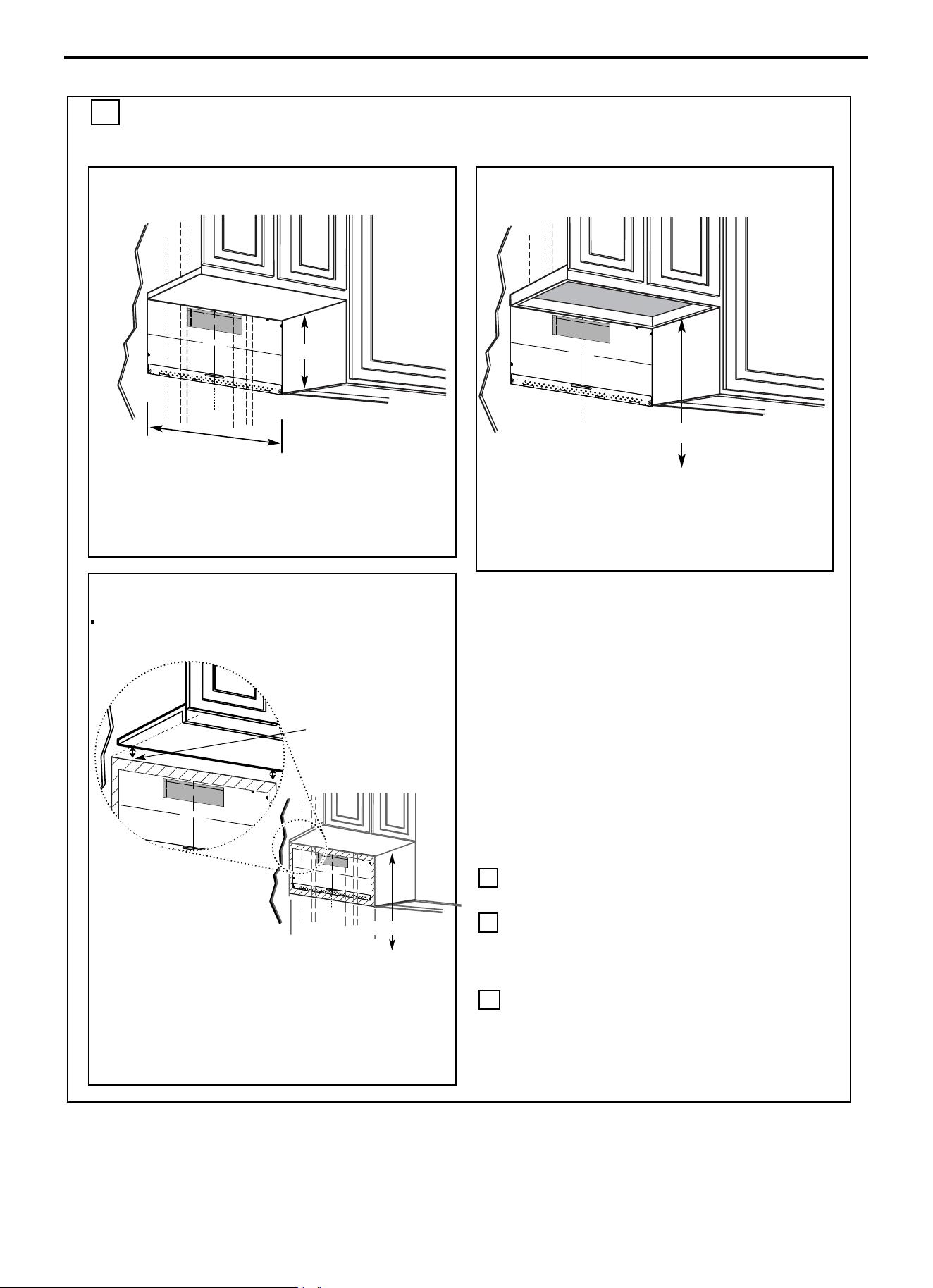
Instructions d’installation
FR-73
C. IDENTIFICATION DE L’EMPLACEMENT DE LA PLAQUE MURALE SOUS
L’ARMOIRE
Position de la plaque-sous l’armoire à
fond plat
Tracer une ligne verticale sur le mur au centre de
l’espace de 24’’ de large.
Coller le gabarit de paroi arrière sur le mur en
faisant correspondre la ligne médiane et en
touchant la partie inférieure de l’armoire.
Position de la plaque- sous le fond en
retrait du cadre de l’armoire
Tracer une ligne verticale sur le mur au centre de
l’espace de 24 pouces.
Coller le gabarit de paroi arrière sur le mur en
faisant correspondre la ligne médiane et en
touchant le cadre de la partie inférieure de
l’armoire.
Position de la plaque-sous l’armoire à
fond en retrait avec porte-à-faux avant
Tracer une ligne sur la paroi arrière égale à la
profondeur du porte-à-faux avant.
Les armoires peuvent avoir des garnitures
décoratives qui interfèrent avec l’installation du
four à micro-ondes. Retirer toute garniture
décorative éventuelle pour installer correctement
le micro-ondes et le mettre à niveau.
LE FOUR À MICRO-ONDES DOIT ÊTRE DE
NIVEAU.
Utiliser un niveau pour s’assurer que le fond de
l’armoire est de niveau.
Si les armoires ont uniquement un porte-à-faux
avant, sans cadre arrière ou latéral, installer la
plaque de montage à la même distance que la
profondeur du porte-à-faux avant. Cela
maintiendra le four à micro-ondes de niveau.
1 Mesurer la profondeur intérieure du porte-à-
faux avant.
2 Tracer une ligne horizontale sur la paroi
arrière à égale distance sous le fond de
l’armoire que la profondeur intérieure du
porte-à-faux avant.
3 Pour ce type d’installation avec porte-à-faux
avant uniquement, aligner les languettes de
montage avec cette ligne horizontale, sans
toucher le fond de l’armoire comme décrit à
l’étape D.
Au moins 24’’
Tracer une ligne sur
la paroi arrière égale
à la profondeur du
porte-à-faux avant.
²
C
3/8" T
O
ED
G
E
N
O
T
E: I
T
IS VER
Y IMPORTANT TO
R
EAD
AND
FOLLOW
THE DIREC
T
IONS
I
N T
HE
I
N
STALL
ATION
INSTRU
C
TION
S
BEF
ORE PROC
EED
I
N
G
W
ITH
TH
IS
R
E
AR
WALL TEM
PLAT
E.
Th
is
Rea
r W
a
l
l T
e
mp
l
a
t
e
se
rve
s to p
ositio
n the bo
tto
m
mo
u
ntin
g
pla
te
and
to lo
ca
te th
e
h
o
rizontal exh
a
u
st
o
u
tlet
.
1. Use
a
le
ve
l to ch
e
ck t
h
a
t the te
mplate
is
p
o
si
tio
ned
a
ccu
rately.
2
.
Loca
te and
ma
rk at least o
n
e stu
d o
n th
e
le
ft o
r
righ
t sid
e
o
f t
h
e cen
ter
line.
It is imp
o
rta
n
t
to use at
lea
st o
n
e wo
o
d
scre
w
mo
u
n
te
d
firmly in
a
stu
d to suppo
rt t
h
e we
ig
ht
o
f
t
he microw
ave. Ma
rk two
a
d
diti
o
nal, evenly
sp
aced
loca
tio
n
s
for t
h
e
supp
l
ied
tog
g
le
bolts.
3
.
D
rill
hole
s
in th
e
m
a
r
ke
d
lo
ca
tio
n
s.
W
here the
re
is
a stud, drill a 3/16" h
ol
e f
o
r wo
o
d screw
s.
Fo
r h
o
le
s
t
h
at do n
o
t lin
e
u
p
with
a
stu
d
,
dr
ill 5/
8" ho
l
e
s fo
r
to
gg
l
e bolt
s.
DO NOT
I
NST
A
L
L THE MOU
NT
IN
G P
LA
TE
AT T
H
IS
T
IME.
4
.
Remo
ve
the temp
la
te
from the
re
a
r wall.
5.
Re
vie
w t
he I
nsta
llatio
n
In
stru
cti
on
book fo
r
you
r
i
n
sta
llation
situation.
Lo
cate and m
ar
k
h
oles
t
o
ali
gn
w
ith
ho
les
in the
m
o
unt
ing
plate
.
I
M
P
O
R
T
ANT:
LOC
AT
E
A
T
LEAST
ON
E ST
UD ON
E
IT
HER
SIDE OF
TH
E
CE
N
T
ER
LI
NE.
M
A
R
K
TH
E
LOCAT
ION
F
OR
2 A
D
D
I
TIO
N
AL, EVENL
Y
SPA
C
ED TOGGL
E BOLT
S IN THE
M
OU
N
TI
NG PLAT
E
AREA.
Loc
at
e
a
nd
mark holes
to
align
with holes
in
t
he
mou
nt
i
ng
plat
e
.
I
MPOR
TANT:
LOCATE AT LEAST
ON
E S
TU
D
ON
E
ITH
ER
SI
D
E OF
THE
CENTE
R
LIN
E
.
MAR
K
TH
E LOC
ATI
ON F
OR
2
A
DDI
TI
ON
AL,
E
VENLY
SPA
C
ED
TOGGLE
BOLTS
IN THE MOUNTIN
G
P
LATE
AREA.
T
rim the re
ar
wall
te
m
pl
ate
al
on
g
th
e
dotted
li
n
e.
T
rim the
rear
wal
l
tem
pl
at
e al
ong
th
e
d
o
tte
d
li
ne.
12"
4
"
Da
r
le
v
ue
lta
a
la
hoja
para
c
ons
ultar
la
v
ers
ión
e
n
Esp
a
ñ
ol.
2″
16-1/2
24"
C
3/
8"
TO
E
DGE
N
OTE:
IT IS
VERY
IMP
O
R
T
A
NT T
O
R
E
AD
A
N
D
FO
LL
O
W
T
H
E
D
IR
E
C
T
ION
S
IN
T
H
E
IN
S
T
A
L
L
ATION
INST
R
UC
T
IO
N
S
B
E
F
OR
E P
R
OCEE
DING WIT
H
T
H
IS
RE
A
R
W
A
LL
T
E
MP
L
A
TE.
This
Re
a
r W
all
Te
mpl
a
t
e
s
er
ve
s
t
o p
o
sit
io
n
t
he
bo
tt
o
m
m
o
u
nti
ng
plat
e
a
nd
t
o lo
ca
t
e
t
h
e
ho
ri
zo
nt
al
e
x
h
au
st
o
u
t
let
.
1.
Us
e
a
lev
el
t
o
c
h
ec
k
t
h
a
t
th
e
t
em
plate
is p
o
s
it
io
n
e
d
a
c
c
u
ra
t
e
ly.
2
.
Lo
c
at
e
an
d
m
ar
k
at
lea
s
t
o
n
e s
t
ud
o
n t
h
e
le
f
t
o
r
ri
ght
s
ide
o
f t
h
e
c
e
n
ter
lin
e
.
It
is
impo
rt
a
n
t
t
o
use at
l
e
a
st
o
ne
w
o
o
d
s
c
re
w
mo
u
n
te
d
f
ir
mly
in
a
st
u
d
to
s
u
p
po
r
t
the
w
e
ight
of
th
e
micr
owa
v
e.
M
ark t
w
o ad
d
iti
o
na
l,
e
v
e
nly
s
pa
c
e
d
loc
at
io
n
s
for
th
e
s
u
pp
lied
t
o
gg
le
bo
lt
s
.
3
.
D
rill
h
ole
s
in
the
m
a
rk
e
d
lo
c
a
t
ion
s
.
Whe
re
th
e
re
is
a
s
t
ud,
d
r
ill
a 3
/
1
6
"
hole
fo
r
w
oo
d
s
c
re
w
s
.
F
or
h
ole
s
th
at
do n
ot
li
n
e
u
p
wit
h
a
s
t
ud
,
drill 5/
8
"
hole
s
for
t
o
gg
le
bo
lt
s.
D
O
N
O
T
I
NS
TALL
T
H
E
MO
U
N
T
I
N
G
P
L
A
TE
AT
TH
IS
TIM
E
.
4
.
R
e
m
o
v
e
t
h
e
te
m
p
la
te
f
rom
t
h
e
r
e
ar
w
al
l.
5.
Re
v
i
e
w
t
h
e
I
n
s
t
a
lla
t
io
n
I
n
s
t
r
u
ct
ion
bo
o
k
f
o
r
y
ou
r
insta
lla
t
ion
s
it
u
at
io
n
.
L
o
c
a
te an
d
ma
rk
h
o
l
es
to
a
li
g
n w
it
h
ho
l
e
s
i
n
the
mo
u
n
t
in
g
p
l
a
te.
IMP
O
R
T
ANT
:
LO
CATE
A
T
LEAS
T
ONE
S
TU
D ON E
I
T
H
ER
S
IDE
O
F
T
HE CE
NTE
R
LIN
E.
MA
RK
T
H
E
LOCAT
ION FO
R
2
A
D
D
ITIO
N
A
L, E
V
E
N
LY
S
P
AC
E
D TOGG
LE B
OL
T
S IN
THE M
O
U
N
T
IN
G P
L
AT
E
A
RE
A
.
Locate a
n
d
ma
r
k ho
l
e
s to
a
lign with holes in
t
h
e
mo
unt
i
ng p
l
a
t
e.
IMPO
RTA
N
T:
LOCA
TE
AT
L
E
AST
ONE
S
T
U
D
ON
EITH
E
R SID
E
O
F
T
H
E
C
ENT
E
R
L
IN
E
.
MARK
TH
E LOC
A
TION
F
OR
2 AD
D
I
T
IONAL
,
E
V
E
N
L
Y
S
PAC
E
D
TO
GG
L
E BOLT
S IN
T
H
E MO
U
N
T
IN
G
P
LAT
E
AR
E
A.
T
r
im
th
e rea
r
w
a
l
l
te
m
p
late
alo
ng th
e do
tte
d
lin
e
.
Trim
th
e r
ear
wa
ll
te
m
p
l
a
te
a
lo
n
g
th
e
d
o
tte
d
line
.
1
2"
4
"
D
a
rle
vu
e
lt
a
a
la
h
o
ja
p
a
ra
c
on
s
u
l
t
a
r
la
v
e
r
si
ó
n
e
n
E
sp
a
ño
l.
C
L
3/8
"
TO EDGE
N
O
TE
:
I
T
IS
VER
Y
IMPORTAN
T T
O
READ
AND FO
LLO
W THE D
IREC
TIO
NS
I
N
TH
E
INST
ALL
ATION
INST
R
U
C
TI
O
N
S
BEFO
RE PRO
C
EED
ING
W
ITH TH
I
S
R
EAR WALL
T
EMPL
AT
E.
Th
is
R
e
a
r W
a
ll Templa
t
e serves
to p
os
it
i
o
n
th
e
b
ot
to
m
mo
u
ntin
g
p
la
te
and t
o l
oc
at
e
the h
o
riz
ontal e
xha
us
t
ou
tle
t.
1.
Us
e
a
lev
el to
c
he
ck
th
a
t
th
e templat
e is
po
sitio
n
ed
a
c
curat
ely.
2
.
Loc
ate
and
ma
r
k
a
t le
a
s
t
o
n
e st
u
d
o
n
t
he left
o
r
r
ig
ht s
id
e
o
f
the ce
nte
r
l
ine.
It
is
i
mpo
rta
nt t
o
u
s
e a
t lea
s
t
one
wo
od
s
c
r
e
w
mo
u
nt
ed firmly
in
a
s
tu
d
to
s
upport the
w
e
ig
ht
of
th
e micro
w
a
ve.
Ma
rk
two
a
d
d
itiona
l,
e
v
enl
y
sp
ace
d
lo
ca
tio
ns fo
r th
e
s
uppli
e
d tog
gle
bo
lts.
3.
D
ril
l h
ole
s in
th
e mark
e
d lo
c
atio
n
s
.
W
h
e
re th
e
re
is
a stu
d
, dr
i
ll a 3
/1
6" ho
le
fo
r w
o
od
s
c
re
w
s
.
For
ho
le
s
th
a
t do no
t lin
e u
p
with a s
tud,
drill 5
/8" h
ole
s fo
r
to
g
gle b
olts
.
D
O NO
T
IN
STA
L
L
TH
E
MO
U
NTING
PL
ATE
AT TH
IS TIME
.
4. Re
m
ov
e
the
template
fr
om t
he
r
e
ar w
all.
5.
Revie
w
the In
s
ta
ll
ation
In
s
tru
c
t
io
n
bo
o
k fo
r your
in
stalla
tion
s
ituatio
n.
Lo
cate an
d
ma
rk
hol
es t
o align with
hol
es
in t
h
e
mounting pla
t
e
.
I
M
PORT
ANT
:
LOC
ATE AT
LEAST
ONE STU
D
ON
EI
THER SI
D
E OF
TH
E C
ENTER
LINE.
MAR
K
T
H
E LOC
ATIO
N
FO
R
2
AD
DI
T
IONAL
,
EVEN
L
Y
SPACED
TOG
GLE BO
L
T
S I
N TH
E MOUNTIN
G
PLATE
AR
EA.
Locate
and
ma
rk
hol
es t
o align w
it
h
h
ol
es
in t
h
e
mounting plat
e.
IMPO
R
TANT:
LOC
ATE AT
LEAS
T ON
E ST
U
D ON EI
T
HER
SIDE
OF
TH
E
C
EN
TERLINE
.
MARK T
HE LO
C
ATION
FO
R 2 AD
D
I
TI
ONAL
, EVENLY
SPA
C
ED
T
O
G
GLE BO
L
T
S I
N
TH
E
MO
UN
TI
NG PLAT
E
AR
EA.
Trim
th
e
rear
wall
template along the
d
otted
li
ne.
Trim
the
rear wall
templ
ate
a
l
ong
th
e dotted
li
ne.
12
"
4"
D
arle
v
u
el
t
a
a
la
h
o
ja
p
ara
c
o
n
s
u
lta
r
la
v
ersi
ó
n
en
E
sp
añol.
24"
24"
30’’ par rapport à la table de cuisson
C
3/
8
"
TO
E
D
GE
NOTE:
I
T
IS
VERY
IMPO
RT
ANT TO
RE
A
D
A
ND FO
LLOW
T
HE DIRECT
IO
NS
IN THE INSTALLA
TION
I
NS
TRUCT
I
ONS
BE
F
OR
E PR
OCE
EDING
WI
T
H
T
HIS
RE
AR WA
LL T
E
MP
LATE
.
Th
i
s
R
ea
r
Wa
l
l
Temp
l
a
te
ser
ves to
p
o
si
t
ion the
b
ot
tom
mo
un
t
in
g p
late
a
n
d t
o
locate
t
h
e
h
o
r
i
z
on
tal
e
xhaust
ou
tl
e
t
.
1
.
Use a
le
ve
l
to
che
ck t
hat
the
t
emp
late
i
s
p
osi
ti
on
ed
a
ccur
ate
ly.
2.
L
oc
ate
and
ma
r
k
at least o
n
e stu
d
on
the l
e
ft
or
r
i
gh
t
s
i
de
o
f th
e
c
ent
e
r
lin
e.
It
i
s
imp
orta
nt t
o use
a
t l
e
ast o
ne
wood
sc
r
ew
m
o
u
n
t
ed
fi
rml
y in
a
stu
d t
o su
ppor
t
the we
i
ght
of th
e m
icrow
ave. Mar
k
tw
o a
d
di
tion
al
,
e
ve
nl
y spa
ce
d
l
ocati
o
ns for the
su
ppl
ie
d
tog
gl
e
b
olts.
3. Drill holes in
the
m
ar
ked
l
oca
tio
n
s. Wh
er
e t
here is
a
stu
d,
d
rill a
3/
1
6"
hole for
w
oo
d scr
e
w
s.
For hol
es
th
a
t
do
n
o
t
lin
e
up w
i
t
h
a
st
u
d,
d
ri
ll
5/8
" h
ol
es f
o
r
t
o
g
gle b
ol
ts
.
D
O
NOT
I
N
STALL
THE
MOUNTIN
G PLA
TE
AT TH
IS T
IME.
4.
R
em
o
ve the
te
mp
la
te
fr
o
m t
h
e rear
w
all.
5.
R
evie
w
the
Insta
l
l
a
tio
n
I
nstruction
b
ook f
o
r yo
ur
i
n
sta
ll
at
io
n si
tuation.
Loc
at
e and
mark
hol
es to
ali
gn with
h
oles
i
n
the
mount
i
ng
plate.
I
MPO
RT
ANT:
LOCA
TE AT LEAST ONE
S
TUD
ON
EIT
HER S
IDE
OF
THE
CENT
ER
L
INE
.
MAR
K THE LOC
A
T
IO
N
FO
R
2
AD
DI
T
IONA
L, E
VE
NLY
SP
A
CE
D
TOGGLE
B
OLT
S
I
N TH
E
MOUNTING PLATE
A
R
EA.
Loc
at
e and
ma
rk h
ol
es
t
o a
l
i
gn
with
hol
e
s in the
moun
t
i
ng pl
at
e.
IMPO
RTANT
:
LOCA
T
E
AT LE
A
ST ONE
S
TUD
ON
EITHE
R
S
IDE
OF
THE CE
NT
ERL
I
NE.
MA
RK T
HE
LOC
AT
ION
FO
R
2
ADDI
T
IONA
L, E
V
ENL
Y
S
PA
CED T
O
GGLE
B
OLTS IN THE
MOUNT
ING PL
A
T
E
A
REA.
Trim
the
rear
wa
ll templ
ate
al
on
g the
dott
e
d lin
e.
T
rim
th
e
rear w
all temp
l
ate
al
ong t
he
do
tt
ed
lin
e.
12"
4"
Darle v
uelt
a
a
la
ho
ja
para
co
n
s
ult
a
r
la
v
ersió
n
en
E
s
p
a
ñ
o
l.
24"
30’’ par rapport à la table de cuisson
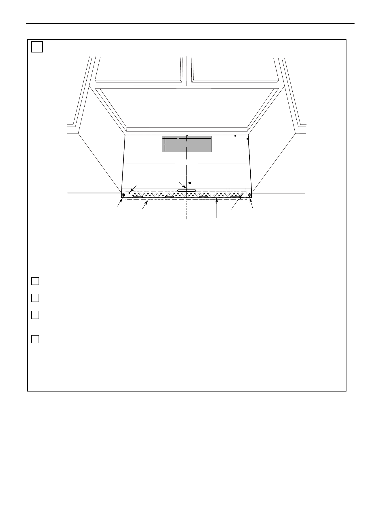
Instructions d’installation
FR-74
D. ALIGNEMENT DE LA PLAQUE MURALE
MISE EN GARDE : Se
munir de gants pour éviter
que les bords tranchants
ne provoquent des
coupures aux doigts.
1 Tracer une ligne verticale sur le mur au centre de
l’espace de 24’’ de large.
2 Tracer une ligne horizontale sur le mur au bas du
« Gabarit de paroi arrière ».
3 Identifier un montant dans la zone « E » de la
plaque de montage. Se reporter à la section 1B
Identification des montants muraux.
4 Pour fixer la plaque de montage dans le montant,
percer un trou de 3/16’’ dans les colombages en
bois. Percer un trou de 5/8’’ pour faire basculer le
boulon à 1 autre endroit (trou A ou trou B)
REMARQUE : NE PAS INSTALLER LA
PLAQUE À CE STADE.
REMARQUE : Les trous A et B se trouvent à
l’intérieur de la zone E. Si aucun des deux trous ne
se situe dans un montant, trouver un montant dans la
zone E et tracer un cercle pour effectuer l’alignement
avec le montant. Il est important d’avoir au moins
une vis à bois fixée fermement dans un montant
pour supporter le poids du micro-ondes. Mettre la
plaque de montage de côté.
Trou B
GABARIT PAROI ARRIÈRE
Trou A
Zone E
Encoches
ligne médiane
Tracer une ligne verticale
sur le mur à partir du
centre du meuble haut.
Ligne horizontale
Ligne horizontale
Tracer une ligne horizontale sur la paroi
au bas du « Gabarit de paroi arrière ».
C
L
3/8" TO EDGE
%#76+10Ä+(':*#756#ਸ਼+5
215+6+10'&
1765+&'
4'%1//'0&'&&+/'05+
10)4'#5'Ä.#&'0#+49+..
&+5%*#4)'+061*175'5647%674'
/+0+/7/9+&6*4'37+4'&
NOTE: IT IS VERY IMPORTANT TO
READ AND FOLLOW THE DI
RECTIONS
IN THE INSTALLATION INSTRUCTIONS
BEFORE PROCEEDI
NG WITH
THIS
REAR WALL TEMPLATE.
This Rear Wal
l Template serves t
o position the bottom
mounting plate and to locate
the horizontal exhaust
outlet.
1. Use a level to check th
at the template is positioned
accurately.
2. Locate and ma
rk at least one stud on the left or
right side of the centerlin
e.
016'
It is important to use at least one wood
screw mounted firmly in a stud to s
upport the weight
of the microwave. Mark two add
itional, evenly spaced
locations for the supp
lied toggle bolts.
3. Drill holes in the marked locatio
ns. Where there is
a stud, drill a 3/16" hole for
wood screws. For hole
s
that do not line up with a st
ud, drill 5/8" holes for
toggle bolts.
016'
DO NOT INSTALL THE M
OUNTING PLATE
AT THIS TIME.
4. Remove the tem
plate from the rear wall.
5. Review the Installation Instru
ction book for your
installation situation.
Locate and mark
holes to align with h
oles in the
mounting plat
e.
IMPORTANT:
LOCATE
AT LEAST ONE
STUD ON EITHER SIDE OF
THE CENTERLINE.
MARK THE LOCATION FOR 2
ADDITIONAL, EVENLY
SPACED
TOGGLE BOLTS IN
THE MOUNTING PLATE
AREA.
Locate and mark
holes to align with hol
es in the
mounting plat
e.
IMPORTANT:
LOCATE
AT LEAST ONE
STUD ON EITHER SIDE OF
THE CENTERLINE.
MARK THE LOCATION FOR 2
ADDITIONAL, EVENLY
SPACED
TOGGLE BOLTS IN
THE MOUNTING PLATE
AREA.
Trim the rear
wall template al
ong the dotted
line.
%
#
$
%
&
(%76176(14*14+<106#.
1765+&'':*#756
%76*1.'6*417)*
4'#49#..
(14':*#756#ਸ਼
12"
4"
Darle vuelta a la hoja para consultar la
versión en Español.
24"
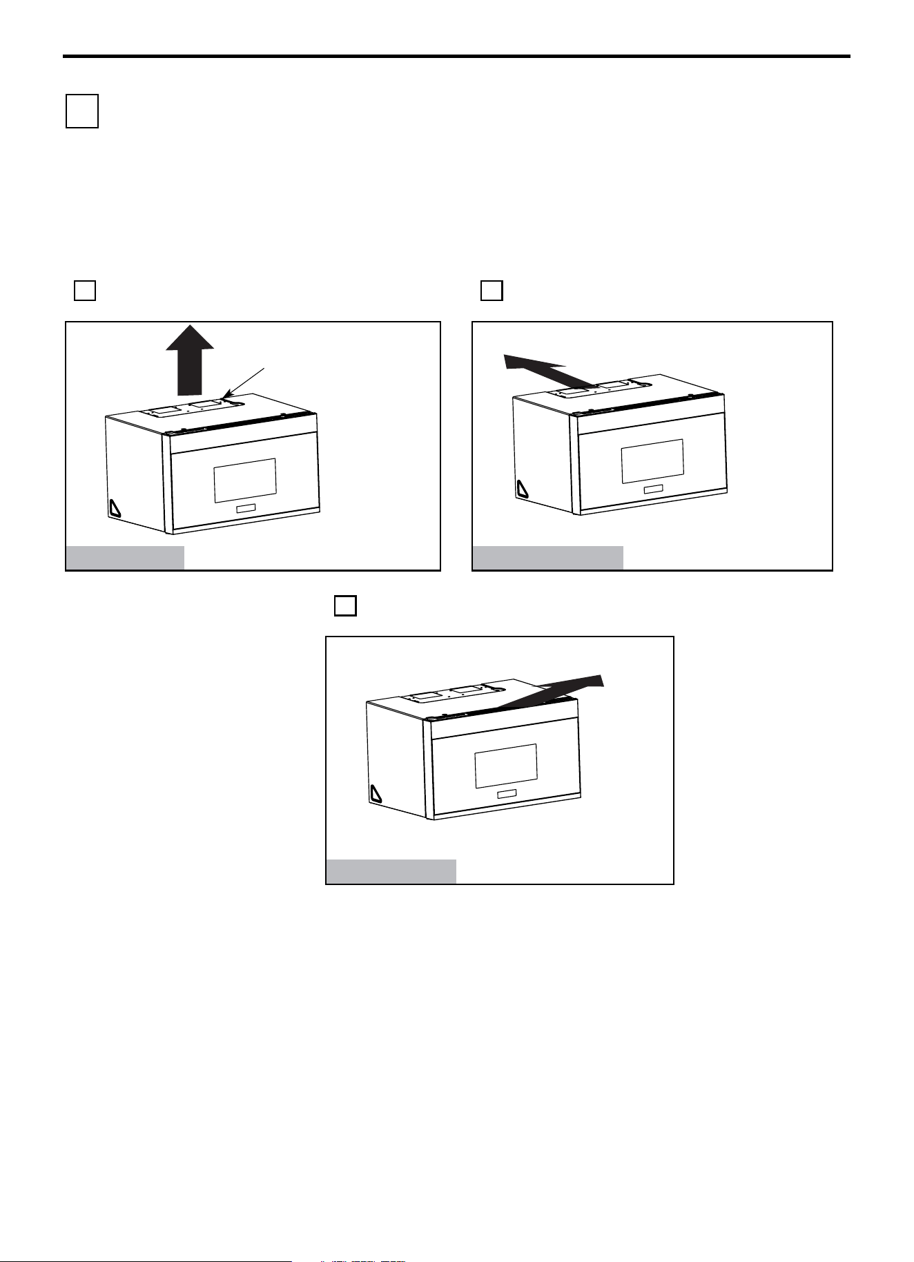
Instructions d’installation
FR-75
2 TYPES D’INSTALLATION (Choisir A, B ou C)
Ce four à micro-ondes est conçu pour s’adapter aux trois
types de ventilation suivants :
A. Échappement haut vers l’extérieur (conduit vertical)
B. Échappement arrière vers l’extérieur (conduit
horizontal)
C. Recirculation (Non ventilé Sans conduit)
REMARQUE : Ce four à micro-ondes est expédié
assemblé pour la recirculation de l’air. Sélectionner le
type de ventilation requis pour votre installation et
poursuivre dans ce chapitre.
A ÉCHAPPEMENT HAUT VERS L’EXTÉRIEUR
(CONDUIT VERTICAL)
B ÉCHAPPEMENT ARRIÈRE VERS
L’EXTÉRIEUR (CONDUIT HORIZONTAL)
Voir page 16
Voir page 16
C RECIRCULATION
(NON-VENTILÉ SANS CONDUIT)
Les modèles sont livrés
avec le type de ventilation
à recirculation de l’air.
Certains modèles sont
équipés d’un filtre à
charbon jetable pour
favoriser l’élimination des
fumées et des odeurs.
Voir page 20
REMARQUE : Lire les deux pages suivantes uniquement si le choix s’est porté sur un système d’échappement
vers l’extérieur. Si l’option de recirculation de l’air dans la pièce a été choisie, passer à la page 20.
Adaptateur en place pour
l’échappement haut vers
l’extérieur
L’adaptateur doit être déplacé
vers l
’arrière pour l’
échappement
haut vers l’extérieur.
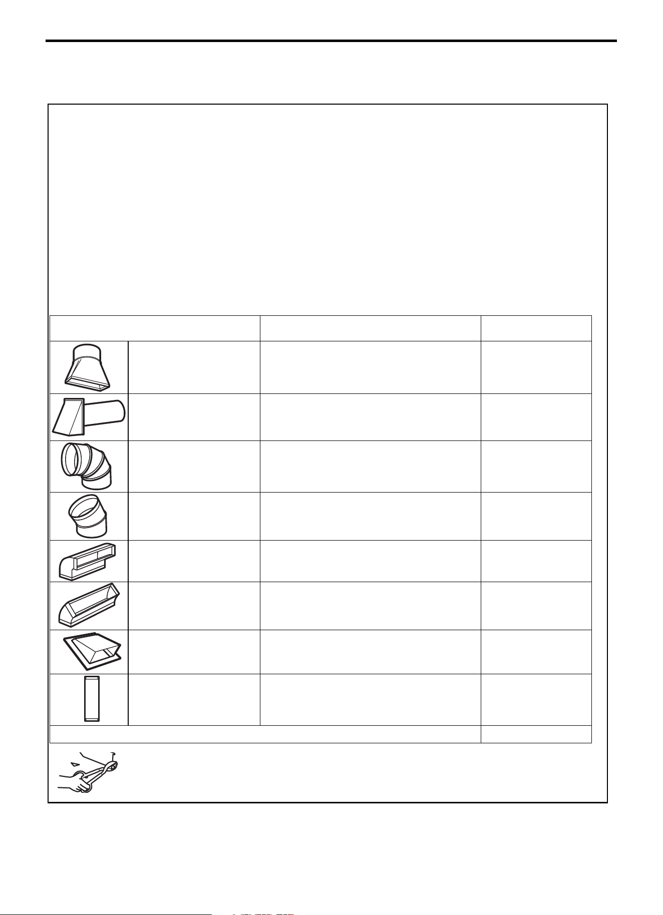
Instructions d’installation
FR-76
INSTRUCTIONS D’INSTALLATION DU CONDUIT D’ÉVACUATION VERS
L’EXTÉRIEUR
REMARQUE : En cas d’installation d’un conduit, noter que la
longueur totale du conduit rectangulaire de 31/4’’ x 10’’ (8,2 x
25,4 cm), ou du conduit circulaire de 5’’ (12,7 cm) / 6’’ (15,2 cm) de
diamètre ne doit pas dépasser 120 pieds équivalents (36,5 m).
La ventilation vers l’extérieur nécessite un CONDUIT
D’ASPIRATION EXTERNE. Lire attentivement ce qui suit.
REMARQUE : Il est important que la ventilation soit installée en
utilisant la voie la plus directe et avec le moins de coudes possible.
Ce qui garantit une évacuation nette des fumées et réduit le risque de
blocages. Vérifier également que les clapets pivotent librement et
que rien ne bloque les conduits.
Raccord d’échappement :
L’adaptateur d’échappement a été conçu pour s’accoupler avec un
conduit rectangulaire standard de 3
1/4" x 10” (8,2 x 25,4 cm).
Si un conduit circulaire est nécessaire, un adaptateur de transition
rectangulaire-circulaire doit être utilisé. Un conduit d’un diamètre
de 5" (12,7cm)/ 6" (15,2cm) peut être utilisé.
Longueur maximale du conduit :
Pour un mouvement d’air satisfaisant, la longueur totale du
conduit rectangulaire de
3W x 10” (8,2 x 25,4 cm) ou du conduit
circulaire de
5” (12,7
cm
) / 6” (15,2 cm) de diamètre ne doit pas
dépasser 120 pieds équivalents (36,5 m).
Les coudes, les transitions, les parois et les
chapeaux de toit, etc.,
présentent une résistance
supplémentaire à la circulation de l’air et équivalent à une
section de conduit droit qui est plus longue que leur taille
physique réelle. Lors du calcul de la longueur totale du conduit,
ajouter les longueurs équivalentes de toutes les transitions et
adaptateurs plus la longueur de toutes les sections droites du
conduit. Le tableau ci-dessous vous montre comment calculer la
longueur totale équivalente des conduits en utilisant les pieds
approximatifs de longueur équivalente de certains conduits
typiques.
PIÈCES DE CONDUIT
LONGUEUR
ÉQUIVALENTE
x
NOMBRE
UTILISÉ
=
LONGUEUR
ÉQUIVALENTE
Adaptateur de transition
rectangulaire-circulaire*
5 pi (1,5 m) x ( ) = Pied ou mètre
Capuchon de mur 40 pi (12,2 m)
x ( ) = Pied ou mètre
Coude 90° 10 pi (3 m) x ( ) = Pied ou mètre
Coude 45° 5 pi (1,5 m) x ( ) = Pied ou mètre
Coude 90° 25 pi (7,6 m) x ( ) = Pied ou mètre
Coude 45° 5 pi (1,5 m) x ( ) = Pied ou mètre
Chapeau de toit 24 pi (7,3 m) x ( ) = Pied ou mètre
Conduit rectiligne 6“ (15,2 cm)
Circulaire ou 3
14“ x 10“
(8,2 x 25,4 cm Rectangulaire)
1 pi (0,3 m) x ( ) = Pied ou mètre
Conduit total
=
Pied ou mètre
* REMARQUE IMPORTANTE : Si un adaptateur de
transition rectangulaire-circulaire est utilisé, les coins
inférieurs de l’amortisseur devront être coupés à l’aide de
cisailles pour l’ajuster et permettre à l’amortisseur de se
déplacer librement.
Les longueurs équivalentes des pièces de conduit sont basées sur des
essais réels et reflètent les exigences de bonne performance de
ventilation
avec n’importe quelle hotte d’aération.
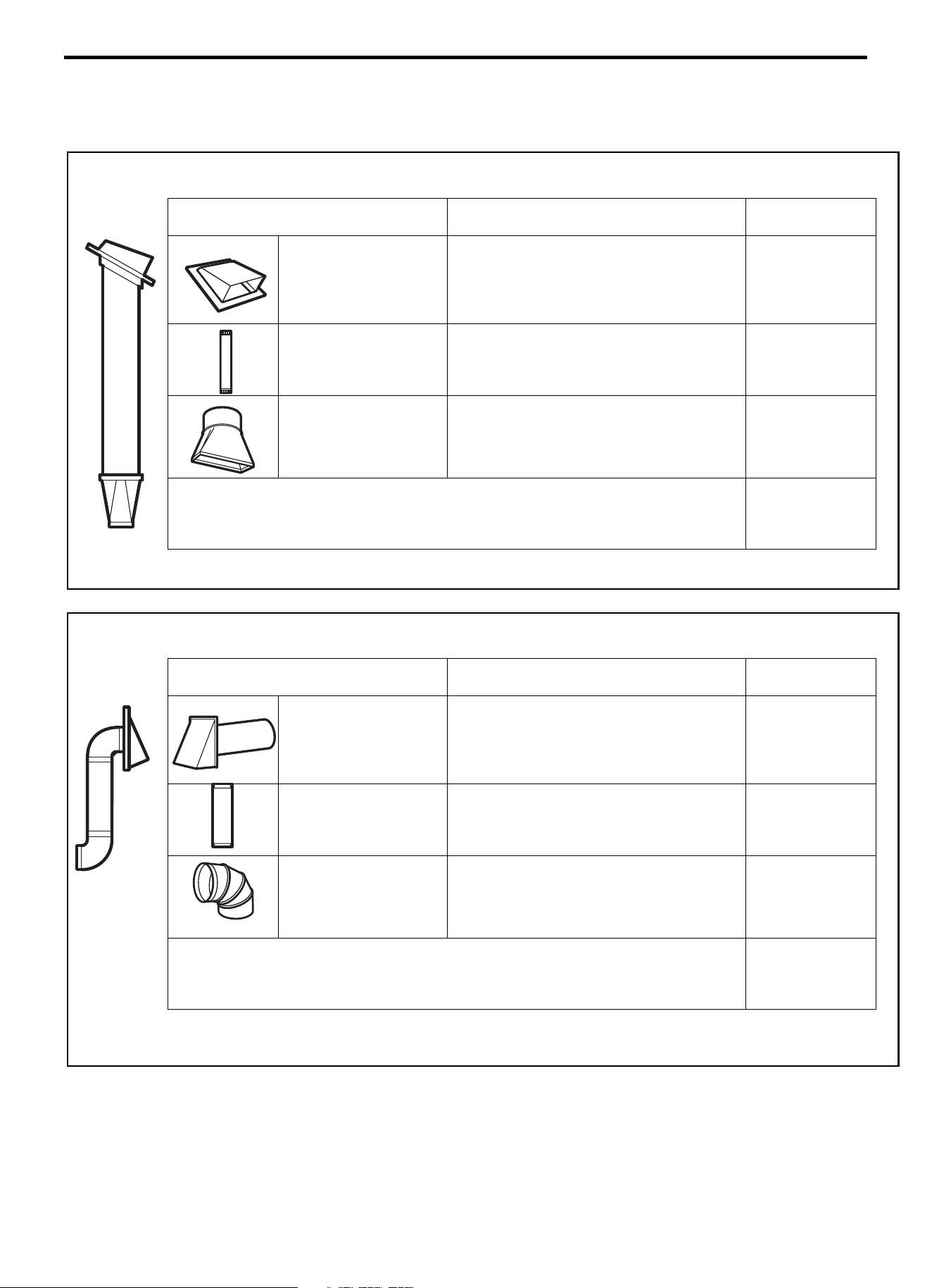
Instructions d’installation
FR-77
CONDUIT D’ÉVACUATION VERS L’EXTÉRIEUR
ÉCHAPPEMENT HAUT VERS L’EXTÉRIEUR (EXEMPLE UNIQUEMENT)
Le tableau suivant fournit un exemple d’installation possible de conduits.
PIÈCES DE CONDUIT
LONGUEUR
ÉQUIVALENTE
x
NOMBRE
UTILISÉ
=
LONGUEUR
ÉQUIVALENTE
Chapeau de toit
24 pi (7,3 m) x (1) = 24 pi (7,3 m)
12 pi (3,6 m)
Conduit rectiligne
(6”/15,2 cm Circulaire)
12 pi (3,6 m) x (1) = 12 pi (3,6 m)
Adaptateur de transition
rectangulaire
-circulaire*
5 pi (1,5 m) x (1) = 5 pi (1,5 m)
Les longueurs équivalentes des pièces de conduit sont basées
sur des essais réels et reflètent les exigences de bonne
performance de ventilation avec n’importe quelle hotte
d’aération.
Longueur totale = 41 pi (12,5 m)
* REMARQUE IMPORTANTE : Si un adaptateur de transition rectangulaire-circulaire est utilisé, les coins inférieurs de
l’amortisseur devront être coupés à l’aide de cisailles pour l’ajuster et permettre à l’amortisseur de se déplacer librement.
ÉCHAPPEMENT ARRIÈRE VERS L’EXTÉRIEUR (EXEMPLE UNIQUEMENT)
Le tableau suivant fournit un exemple d’installation possible de conduits.
PIÈCES DE CONDUIT
LONGUEUR
ÉQUIVALENTE
x
NOMBRE
UTILISÉ
=
LONGUEUR
ÉQUIVALENTE
Capuchon de mur
40 pi (12,2 m) x (1) = 40 pi (12,2 m)
3 pi Conduit rectiligne
(31/4” x 10”/8,2 x 25,4 cm
Rectangulaire)
3 pi (0,9 m) x (1) = 3 pi (0,9 m)
Coude 90°
10 pi (3 m) x (2) = 20 pi (3 m)
Les longueurs équivalentes des pièces de conduit sont basées
sur des essais réels et reflètent les exigences de bonne
performance de ventilation avec n’importe quelle hotte
d’aération.
Longueur totale = 63 pi (19,2 m)
REMARQUE : Pour l’échappement arrière, il faut veiller à aligner l’échappement avec l’espace entre les montants
muraux, ou le mur doit être préparé au moment de sa construction en laissant suffisamment d’espace entre les montants
muraux pour accueillir le conduit d’évacuation.
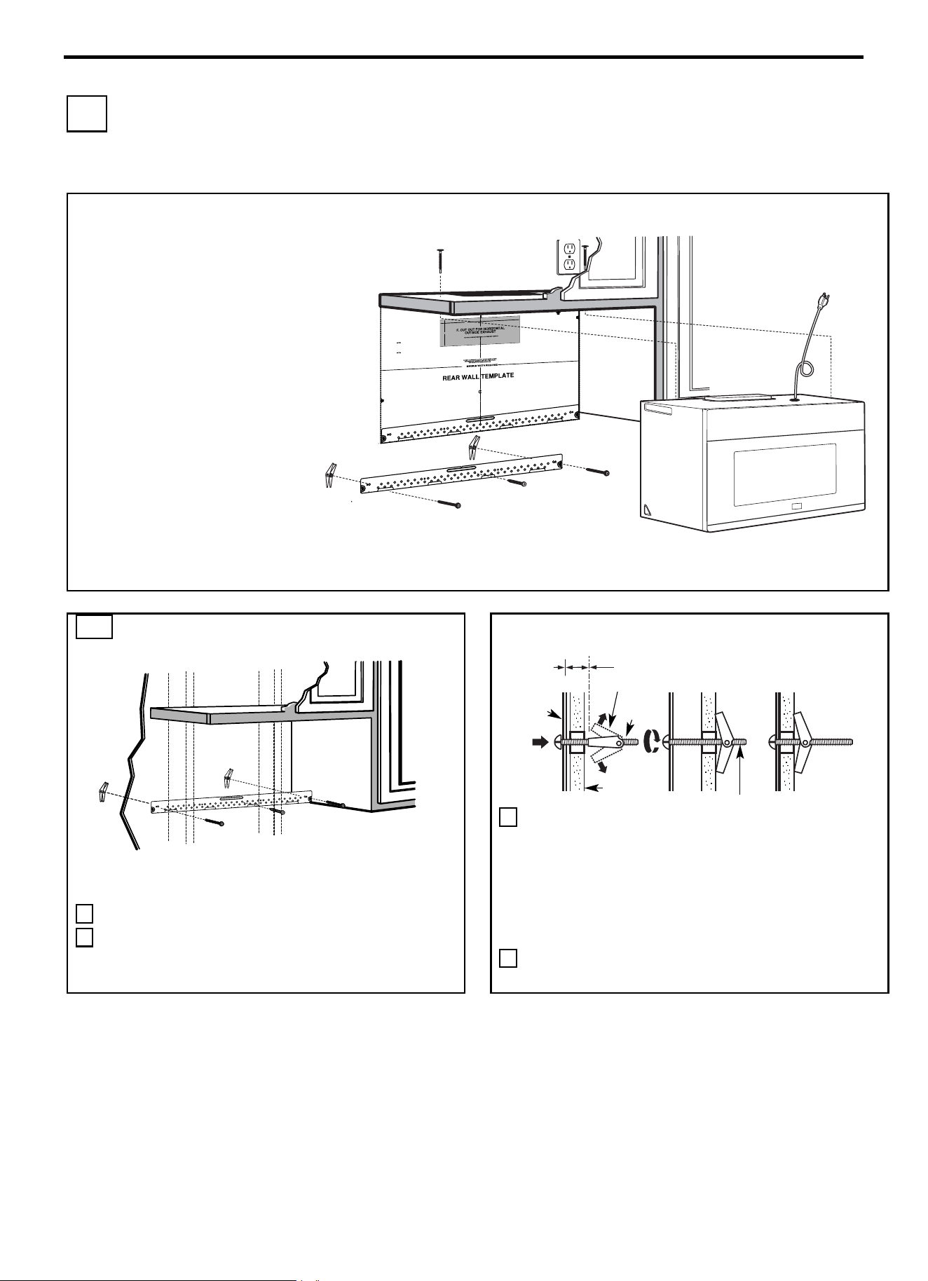
Instructions d’installation
FR-78
A ÉCHAPPEMENT HAUT VERS L’EXTÉRIEUR
(Conduit vertical)
VUE D’ENSEMBLE DE
L’INSTALLATION
A1. Fixer la plaque de montage à la paroi
A2. Préparer le meuble haut
A3. Réglage du ventilateur du micro-
ondes pour l’échappement haut vers
l’extérieur
A4. Contrôle du fonctionnement de
l’amortisseur
A5. Installation du four à micro-ondes
A6. Réglage de l’adaptateur du conduit
d’évacuation
A7. Raccordements des conduits
REMARQUES IMPORTANTES :
• Vérifier que les vis fixant le moteur et
la plaque du ventilateur sont
correctement serrées lorsqu’elles sont
réinstallées. Cette précaution permet
d’éviter les vibrations excessives.
• Vérifier que le câblage du moteur a été
correctement disposé et sécurisé, et
que les fils ne sont pas coincés.
A1. FIXER LA PLAQUE DE MONTAGE À
LA PAROI
Fixer la plaque à la paroi à l’aide de boulons à ailettes. Au moins
une vis à bois doit être utilisée pour fixer la plaque à un montant
mural.
1 Retirer les ailettes des boulons.
2 Insérer les boulons dans la plaque de montage à travers les
trous prévus pour pénétrer dans les cloisons sèches, puis
réinstaller les ailettes de ¾” (19 mm) sur chaque boulon.
Utilisation de boulons à ailettes :
3 Poser la plaque de montage contre le mur et insérer les ailettes
dans les trous du mur pour fixer la plaque.
REMARQUE : Avant de serrer les boulons à ailettes et la vis à
bois, vérifier que le bas de la plaque de montage touche le bas de
l’armoire lorsqu’elle est poussée au ras du mur et que la plaque
est correctement centrée sous l’armoire.
MISE EN GARDE : Veiller à ne pas pincer les doigts entre
l’arrière de la plaque de montage et le mur.
4 Serrer tous les boulons. Retirer la plaque du mur pour faciliter
le serrage des boulons.
Espacement pour les ailettes
supérieur à l’épaisseur de la paroi
Plaque de
montage
Ailettes
Boulon à
ailettes
Extrémité de boulon
Paroi
3/8"TO
EDG
E
NOTE: IT IS VERY
I
MPOR
TANT TO
READ AND FOLLOW
THE
D
IRECTIONS
IN THE INSTALLAT
ION INSTRU
CTI
O
N
S
BE
FO
RE PR
O
CEEDING
WITH T
H
IS
REAR W
ALL TEM
PLATE
.
Th
i
s
R
ea
rWa
ll Template ser
v
e
s to positio
n th
e
botto
m
mounting platea
nd
to loc
ate th
e hor
i
z
on
tal exhau
st
ou
t
let.
1. Us
e a l
evelto
ch
ec
k
th
at the
tem
pla
te is po
s
itioned
a
ccu
r
ately
.
2. L
oc
ate
andmar
k at lea
st o
nes
tu
d on th
e
le
ft or
r
ight side of the cen
te
rli
ne
.
It is importa
n
t to u
se at leas
t
one wood
scre
w
mounted firmly
i
n a s
tud
to supp
ort the weight
ofthe mic
r
ow
a
ve. Mark t
w
o
a
dditi
on
a
l, ev
en
ly
spa
c
ed
lo
c
atio
ns
fo
r the
s
uppl
ied to
g
gle bol
t
s.
3. Dri
ll
h
ol
es in
the mar
k
ed locatio
ns
.Wher
e t
h
er
e is
a s
tud, dr
il
l
a 3/1
6"
h
ol
e fo
r wood scr
ews. F
or
holes
that
do
n
o
t line upw
ith
a
s
tud, dr
il
l 5/8" h
oles
fo
r
toggl
e bolts
.
DO NOT
IN
S
T
AL
L
T
HE MO
U
NTIN
G P
L
ATE
AT
T
HIS
T
IME.
4. Re
move
th
e template fr
o
m
the rea
r
wal
l.
5.Review
the In
s
tall
a
tionInst
ructio
n bo
ok for
y
our
insta
l
l
ation si
tua
t
i
on
.
Locate and mar
k holes
to align with holes
in t
he
mountingp
late.
IMPO
RTANT
:
LOCATE
AT LEA
ST
O
N
E
STUD
O
N EI
THER
SI
D
E O
F
THE
CENTE
R
LI
N
E.
MARK
T
HE LOCATIO
NF
O
R 2 ADDITIONAL, EV
ENL
Y
SP
ACED TOGGLE BO
LTS IN THE MOUN
TING
PLATE
AREA
.
Locate and mar
k holes to ali
gn with holes
in t
he
mountingplate.
IMP
ORTANT
:
LOC
A
TE AT LEAST O
NE
STUD
O
N EI
THER SI
D
E O
F
TH
E
CENT
ERLI
N
E
.
MARK
THE LOCATIO
N
FOR 2 ADDITION
A
L, EVENLY
SPACEDTOGGLE BOLTS IN THE MO
UNTING PLATE
AREA.
Trim the r
e
ar wall tem
plat
e alongthe do
tt
ed line.
Trim the rear
wall tem
pla
t
e alongthe dotted lin
e.
12"
4"
Da
r
l
evue
lt
a
a
la
ho
j
a
pa
ra
consu
l
t
ar
la
ver
sión
en
Espa
ñol.
24"
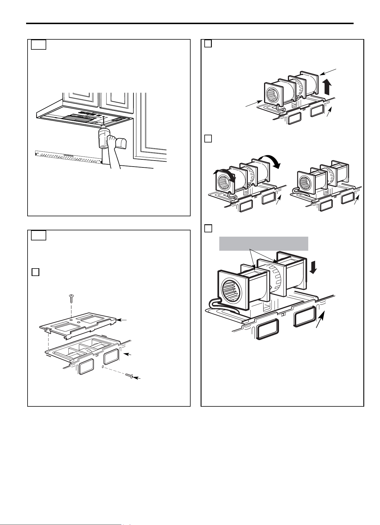
Instructions d’installation
FR-79
A2. PRÉPARATION DU MEUBLE HAUT A
L’AIDE DU GABARIT RESPECTIF
Il est nécessaire de percer des trous pour les vis du support
supérieur, un trou suffisamment grand pour le passage du cordon
d’alimentation, et une découpe assez grande pour l’adaptateur
d’échappement.
• Lire les instructions relatives au GABARIT MEUBLE HAUT.
• Le coller sous le meuble haut.
• Percer les trous en suivant les instructions du GABARIT
MEUBLE HAUT.
MISE EN GARDE : Se munir de lunettes de sécurité au moment
de percer des trous dans le fond de l’armoire.
2
Retirer délicatement le ventilateur. Les fils s’étendront
suffisamment loin pour permettre d’ajuster facilement le
ventilateur.
3 Faire pivoter le ventilateur à 90° de façon à orienter les aubes
du ventilateur vers le haut du four à micro-ondes.
4 Réinstaller le ventilateur dans l’ouverture.
MISE EN GARDE : Ne pas tirer ou tendre le
câblage du ventilateur. Vérifier que les fils ne sont
pas écrasés et qu’ils sont correctement fixés.
A3. RÉGLAGE DU VENTILATEUR DU
MICRO-ONDES POUR
L’ÉCHAPPEMENT HAUT VERS
L’EXTÉRIEUR
1 Placer le four à micro-ondes en position verticale, avec le haut
de l’appareil orienté vers le haut.
Déposer la vis qui fixe la plaque du ventilateur au four à
micro-ondes. Déposer et conserver la vis qui fixe le moteur
du ventilateur au four à micro-ondes.
APRÈS : Ouvertures des aubes du
ventilateur orientées vers le haut
Dos du four à
micro
-ondes
Dos du four à
micro
-ondes
Dos du four à
micro
-ondes
Avant rotation
Après rotation
Extrémité B
Extrémité A
Dos du four à
micro
-ondes
Dos du four à
micro-ondes
Plaque du ventilateur
Moteur du
ventilateur
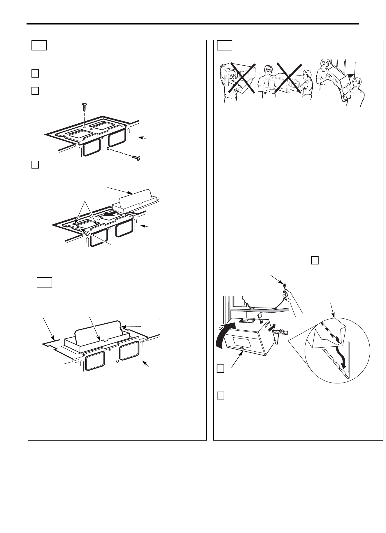
Instructions d’installation
FR-80
A3. RÉGLAGE DU VENTILATEUR DU
MICRO-ONDES POUR L’ÉCHAPPEMENT
HAUT VERS L’EXTÉRIEUR
5 Fixer le ventilateur au micro-ondes à l’aide de la vis déposée à
l’Étape 1. Vérifier que la vis est bien serrée.
6 Réinstaller la plaque du ventilateur à l’aide de la vis déposée à l’Étape 1.
Vérifier que la vis est bien serrée.
7 Fixer l’adaptateur d’échappement à la partie supérieure de la plaque
du ventilateur en le faisant glisser dans les guides de la plaque du
ventilateur.
Pousser fermement jusqu’à ce qu’il se bloque dans les languettes de
verrouillage. S’assurer que la charnière de l’amortisseur est installée
de manière à permettre à l’amortisseur d’osciller librement.
A4. CONTRÔLE DU BON
FONCTIONNEMENT DE
L’AMORTISSEUR
• Vérifier que le ruban de fixation de l’amortisseur a été retiré et
que l’amortisseur pivote de manière aisée avant d’installer le
micro-ondes.
• Quelques réglages seront nécessaires pour garantir un alignement
correct avec le conduit d’évacuation de l’habitation une fois le micro-
ondes installé.
A5. MONTAGE DU FOUR À MICRO-
ONDES
POUR FACILITER L’INSTALLATION ET LA SÉCURITÉ
PERSONNELLE, NOUS RECOMMANDONS QUE DEUX
PERSONNES SOIENT PRÉSENTES POUR INSTALLER CE
FOUR À MICRO-ONDES.
REMARQUE IMPORTANTE : Ne pas saisir ou utiliser la
poignée ou la protection thermique pendant l’installation. Ne
pas retirer les entretoises en carton présentes entre la
protection thermique et la porte.
REMARQUE : Si l’armoire est en métal, utiliser le passe-fil en
nylon autour du trou du cordon d’alimentation pour éviter les
coupures au niveau du cordon.
REMARQUE : Nous recommandons d’utiliser des blocs de
remplissage si l’avant de l’armoire dépasse sous l’étagère
inférieure de l’armoire.
REMARQUE IMPORTANTE : En l’absence de blocs de
remplissage, un serrage excessif des vis risque d’endommager
le caisson.
3 Insérer une vis auto-alignante dans le trou central supérieur du
meuble. Fixer temporairement le four en tournant la vis d’au
moins deux tours complets après l’engagement des filetages.
(La vis sera complètement resserrée plus tard.) Vérifier que le
cordon d’alimentation est toujours bien tendu. Veiller à ne
pas coincer le cordon, en particulier, lors du montage au ras
de la base du meuble.
Dos du four
à micro
-
ondes
Plaque du ventilateur
Adaptateur d’échappement
Amortisseur
Adaptateur
Guide
Languette
d
Dos du four à
micro-ondes
Dos du four à
micro
-ondes
REMARQUE : Lors du montage
du four à micro-
ondes, fileter le
cordon d’
alimentation à travers le
trou situé au fond du meuble haut.
Le maintenir tendu tout au long des
étapes 1 à 3. Ne pas coincer le
cordon ou soulever le four en tirant
sur le cordon.
1 Soulever le micro-ondes,
l’incliner vers l’avant et
accrocher les fentes du
bord inférieur arrière sur
quatre languettes
inférieures de la plaque
de montage.
2 Faire pivoter l’avant
du four contre la base
du meuble.
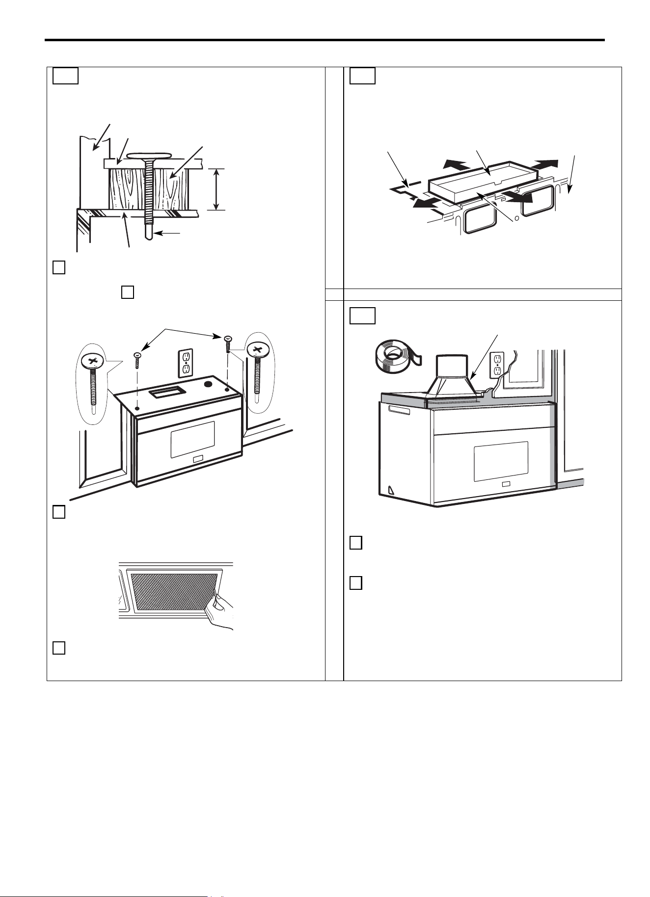
Instructions d’installation
FR-81
A5. MONTAGE DU FOUR À MICRO-
ONDES (suite)
4 Fixer le four à micro-ondes au meuble haut.
5 Insérer 2 vis auto-alignantes à travers les
trous supérieurs extérieurs du meuble.
Effectuer deux tours complets sur chaque vis.
6 Serrer les deux vis extérieures situées sur le dessus du four à
micro-ondes. (Tout en serrant les vis, maintenir le four à
micro-ondes en place contre la paroi et le meuble haut.)
7 Installer les filtres à graisses. Voir la section Utilisation et
Entretien fourni avec le four à micro-ondes.
A6. RÉGLAGE DE L’ADAPTATEUR
D’ÉCHAPPEMENT
Ouvrir le meuble haut et ajuster l’adaptateur d’échappement pour le
raccorder au conduit de l’habitation.
A7. RACCORDEMENT DE CONDUITS
1 Prolonger le conduit de l’habitation vers le bas pour le
raccorder à l’adaptateur d’échappement.
2 Sceller les raccords du conduit d’évacuation à l’aide de ruban
adhésif spécifique pour les applications à haute température.
Avant de
l’armoire
Bloc de
remplissage
Étagère inférieure de
l’armoire
Égal à la
profondeur du
renfoncement
de l’armoire
Vis auto-alignante
Dessus du four à micro-ondes
Plaque du ventilateur
Dos du four à
micro-
ondes
Amortisseur
Pour un réglage de l’avant
vers l
’arrière ou d’un côté à
l
’autre, faire glisser
l
’adaptateur d’
échappement
si nécessaire.
Conduit de maison
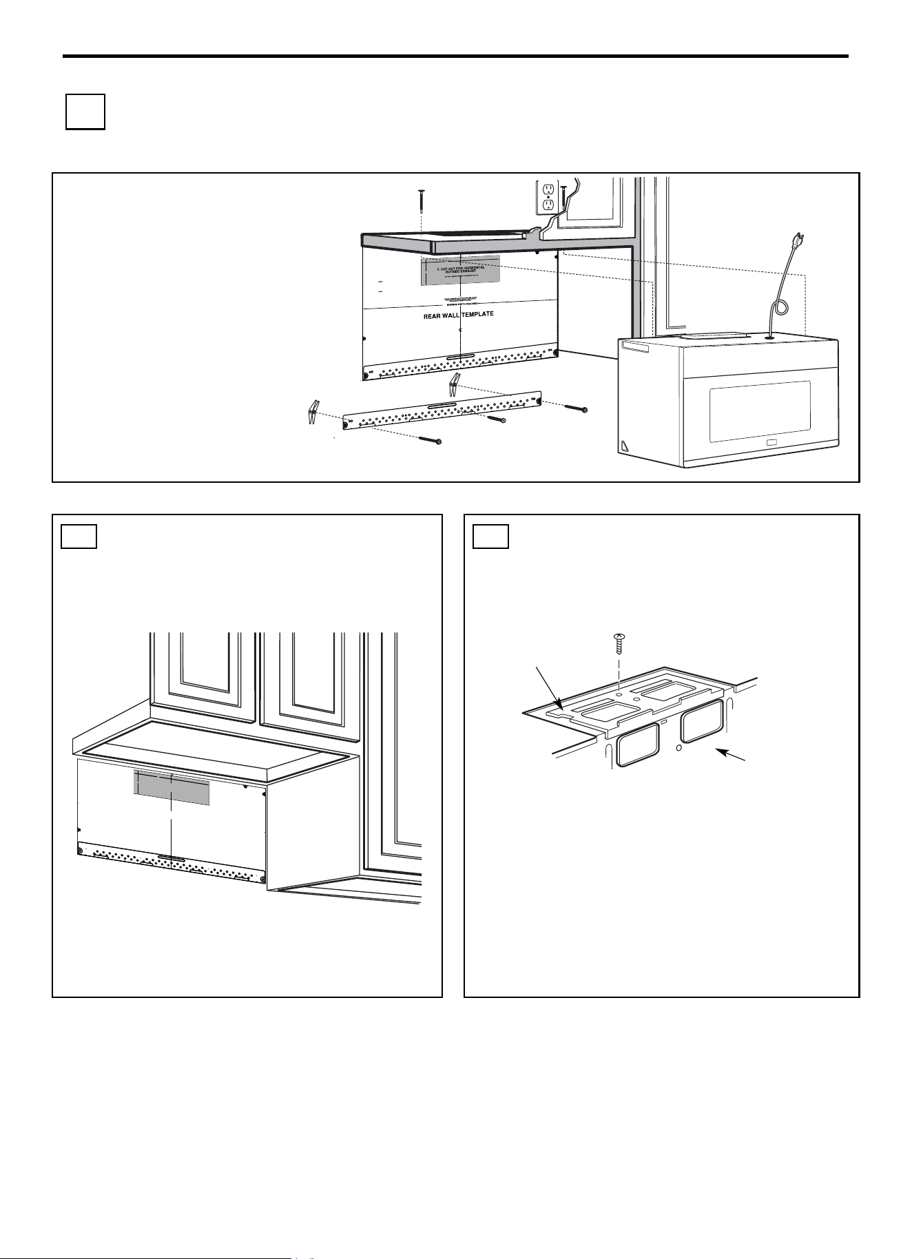
Instructions d’installation
FR-82
B ÉCHAPPEMENT ARRIÈRE VERS L’EXTÉRIEUR (Conduit
horizontal)
VUE D’ENSEMBLE DE
L’INSTALLATION
B1. Préparer la paroi arrière
B2. Déposer la plaque du ventilateur
B3. Fixer la plaque de montage à la paroi
B4. Préparer le meuble haut
B5. Ajuster le ventilateur
B6. Installer le four à micro-ondes
REMARQUES IMPORTANTES :
• Vérifier que les vis fixant le moteur et la
plaque du ventilateur sont correctement
serrées lorsqu’elles sont réinstallées.
Cette précaution permet d’éviter les
vibrations excessives.
• Vérifier que le câblage du moteur a été
correctement disposé et sécurisé, et que
les fils ne sont pas coincés.
B1. PRÉPARATION DE LA PAROI
ARRIÈRE POUR L’ÉCHAPPEMENT
ARRIÈRE VERS L’EXTÉRIEUR
Une ouverture doit être découpée dans la paroi arrière pour
l’échappement vers l’extérieur.
Lire les instructions sur le GABARIT DE PAROI ARRIÈRE.
• Coller le gabarit sur la paroi arrière.
• Découper l’ouverture en suivant les instructions du GABARIT
DE PAROI ARRIÈRE.
B2. DÉPOSE DE LA PLAQUE DU
VENTILATEUR
Retirer et conserver la vis qui fixe la plaque du ventilateur au four à
micro-ondes. Soulever et dégager la plaque du ventilateur.
Plaque du ventilateur
Dos du four à
micro
-ondes
3/8" TO EDGE
NOTE: IT IS VE
RY IMPORTANT TO
READ AND FOLLOW THE DIRECTIONS
IN THE INSTALLATION INSTRUCTIONS
BEFORE PROCEEDING WITH THIS
REAR WALL TEMPLATE.
This Rear Wall Template serves to position the bottom
mounting plate and to locate the horizontal exhaust
outlet.
1. Use a level to check that the template is positioned
accurately.
2. Locate and mark at least one stud on the left or
right side of the centerline.
It is important to use at least one wood
screw mounted firmly in a stud to support the weight
of the microwave. Mark two additional, evenly spaced
locations for the supplied toggle bolts.
3. Drill holes in the marked locations. Where there is
a stud, drill a 3/16" hole for wood screws. For holes
that do not line up with a stud, drill 5/8" holes for
toggle bolts.
DO NOT INSTALL THE MOUNTING PLATE
AT THIS TIME.
4. Remove the template from the rear wall.
5. Review the Installation Instruction book for your
installation situation.
Locate and mark holes to align with holes in the
mounting plate.
IMPORTANT:
LOCATE
AT LEAST ON
E STUD ON EITHER SIDE OF
THE CENTERLINE.
MARK THE LOCATION FOR
2 ADDITIONAL, EVENLY
SPACED TOGGLE BOLTS IN THE MOUNTING PLATE
AREA.
Locate and mark holes to align with holes in the
mounting plate.
IMPORTA
NT:
LOCATE AT LEAST ONE STUD ON EITHER SIDE OF
THE CENTERLINE.
MARK THE LOCATION FOR 2 ADDITIONAL, EVENLY
SPACED TOGGLE BOLTS IN THE MOUNTING PLATE
AREA.
Trim the rear wall template along the dotted line.
Trim the rear wall template along the dotted line.
12"
4"
Darle vuelta a la hoja para consultar la
versión en Español.
24"
3/8"TO
EDG
E
NOTE: IT IS VERY
I
MPOR
TANT TO
READ AND FOLLOW
THE
D
IRECTIONS
IN THE INSTALLAT
ION INSTRU
CTI
O
N
S
BE
FO
RE PR
O
CEEDING
WITH T
H
IS
REAR W
ALL TEM
PLATE
.
Th
i
s
R
ea
rWa
ll Template ser
v
e
s to positio
n th
e
botto
m
mounting platea
nd
to loc
ate th
e hor
i
z
on
tal exhau
st
ou
t
let.
1. Us
e a l
evelto
ch
ec
k
th
at the
tem
pla
te is po
s
itioned
a
ccu
r
ately
.
2. L
oc
ate
andmar
k at lea
st o
nes
tu
d on th
e
le
ft or
r
ight side of the cen
te
rli
ne
.
It is importa
n
t to u
se at leas
t
one wood
scre
w
mounted firmly
i
n a s
tud
to supp
ort the weight
ofthe mic
r
ow
a
ve. Mark t
w
o
a
dditi
on
a
l, ev
en
ly
spa
c
ed
lo
c
atio
ns
fo
r the
s
uppl
ied to
g
gle bol
t
s.
3. Dri
ll
h
ol
es in
the mar
k
ed locatio
ns
.Wher
e t
h
er
e is
a s
tud, dr
il
l
a 3/1
6"
h
ol
e fo
r wood scr
ews. F
or
holes
that
do
n
o
t line upw
ith
a
s
tud, dr
il
l 5/8" h
oles
fo
r
toggl
e bolts
.
DO NOT
IN
S
T
AL
L
T
HE MO
U
NTIN
G P
L
ATE
AT
T
HIS
T
IME.
4. Re
move
th
e template fr
o
m
the rea
r
wal
l.
5.Review
the In
s
tall
a
tionInst
ructio
n bo
ok for
y
our
insta
l
l
ation si
tua
t
i
on
.
Locate and mar
k holes
to align with holes
in t
he
mountingp
late.
IMPO
RTANT
:
LOCATE
AT LEA
ST
O
N
E
STUD
O
N EI
THER
SI
D
E O
F
THE
CENTE
R
LI
N
E.
MARK
T
HE LOCATIO
NF
O
R 2 ADDITIONAL, EV
ENL
Y
SP
ACED TOGGLE BO
LTS IN THE MOUN
TING
PLATE
AREA
.
Locate and mar
k holes to ali
gn with holes
in t
he
mountingplate.
IMP
ORTANT
:
LOC
A
TE AT LEAST O
NE
STUD
O
N EI
THER SI
D
E O
F
TH
E
CENT
ERLI
N
E
.
MARK
THE LOCATIO
N
FOR 2 ADDITION
A
L, EVENLY
SPACEDTOGGLE BOLTS IN THE MO
UNTING PLATE
AREA.
Trim the r
e
ar wall tem
plat
e alongthe do
tt
ed line.
Trim the rear
wall tem
pla
t
e alongthe dotted lin
e.
12"
4"
Da
r
l
evue
lt
a
a
la
ho
j
a
pa
ra
consu
l
t
ar
la
ver
sión
en
Espa
ñol.
24"
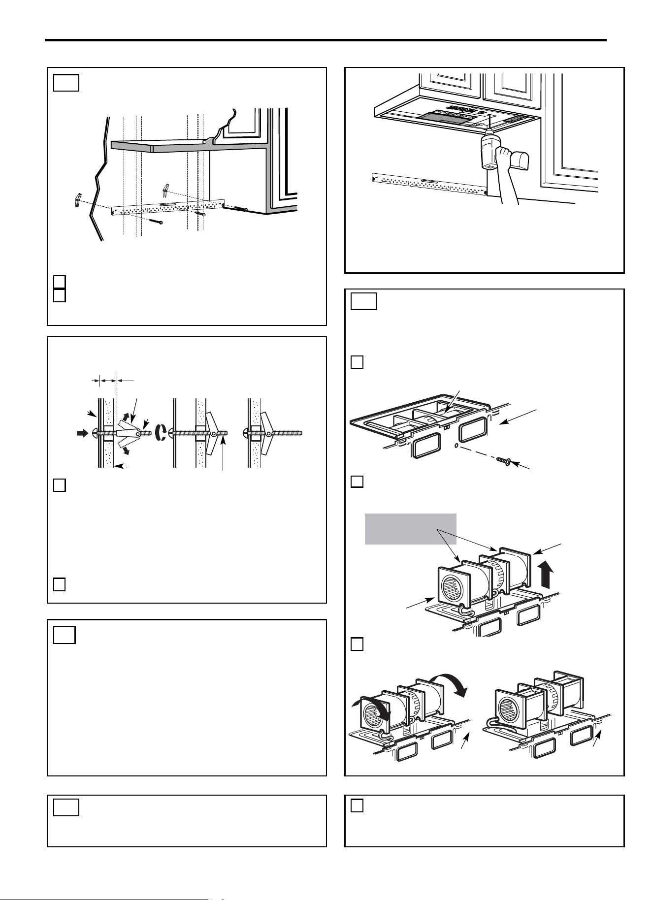
Instructions d’installation
FR-83
B3. FIXER LA PLAQUE DE MONTAGE À
LA PAROI
Fixer la plaque à la paroi à l’aide de boulons à ailettes.
Au moins une vis à bois doit être utilisée pour fixer la plaque à un
montant mural.
1 Retirer les ailettes des boulons.
2 Insérer les boulons dans la plaque de montage à travers les
trous prévus pour pénétrer dans les cloisons sèches, puis
réinstaller les ailettes de ¾” (19 mm) sur chaque boulon
• Lire les instructions relatives au GABARIT MEUBLE HAUT.
• Le coller sous le meuble haut.
• Percer les trous en suivant les instructions du GABARIT
MEUBLE HAUT.
MISE EN GARDE : Se munir de lunettes de sécurité au moment
de percer des trous dans le fond de l’armoire.
B5. RÉGLAGE DU VENTILATEUR DU
MICRO-ONDES POUR
L’ÉCHAPPEMENT ARRIÈRE VERS
L’EXTÉRIEUR
1 Déposer et conserver la vis qui fixe le moteur du ventilateur au
four à micro-ondes.
2
Retirer délicatement le ventilateur. Les fils s’étendront
suffisamment loin pour permettre d’
ajuster facilement le
ventilateur.
3 Faire pivoter le ventilateur de 90°.
Utilisation de boulons à ailettes :
3 Poser la plaque de montage contre le mur et insérer les ailettes
dans les trous du mur pour fixer la plaque.
REMARQUE : Avant de serrer les boulons à ailettes et la vis à
bois, vérifier que le bas de la plaque de montage touche le bas de
l’armoire lorsqu’elle est poussée au ras du mur et que la plaque
est correctement centrée sous l’armoire.
MISE EN GARDE : Veiller à ne pas pincer les doigts entre
l’arrière de la plaque de montage et le mur.
4 Serrer tous les boulons. Retirer la plaque du mur pour faciliter
le serrage des boulons.
B4. PRÉPARATION DU MEUBLE HAUT
A L’AIDE DU GABARIT RESPECTIF
Il est nécessaire de percer des trous pour les vis du support
supérieur et un trou suffisamment grand pour faire passer le cordon
d’alimentation.
B5. RÉGLAGE DU VENTILATEUR DU
MICRO-ONDES POUR
L’ÉCHAPPEMENT ARRIÈRE VERS
8 Réinstaller le ventilateur dans l’ouverture.
Dos du four à
micro
-ondes
Dos du four à
micro
-ondes
Avant rotation
Après rotation
Extrémité A
Extrémité B
Avant : Ouverture des
aubes du ventilateur
orientées vers l
’avant
Moteur du ventilateur
Vis du moteur du
ventilateur
Dos du four à
micro-ondes
Espacement pour les ailettes
supérieur à l’épaisseur de la paroi
Plaque de
montage
Ailettes
Boulon à
ailettes
Extrémité de boulon
Paroi
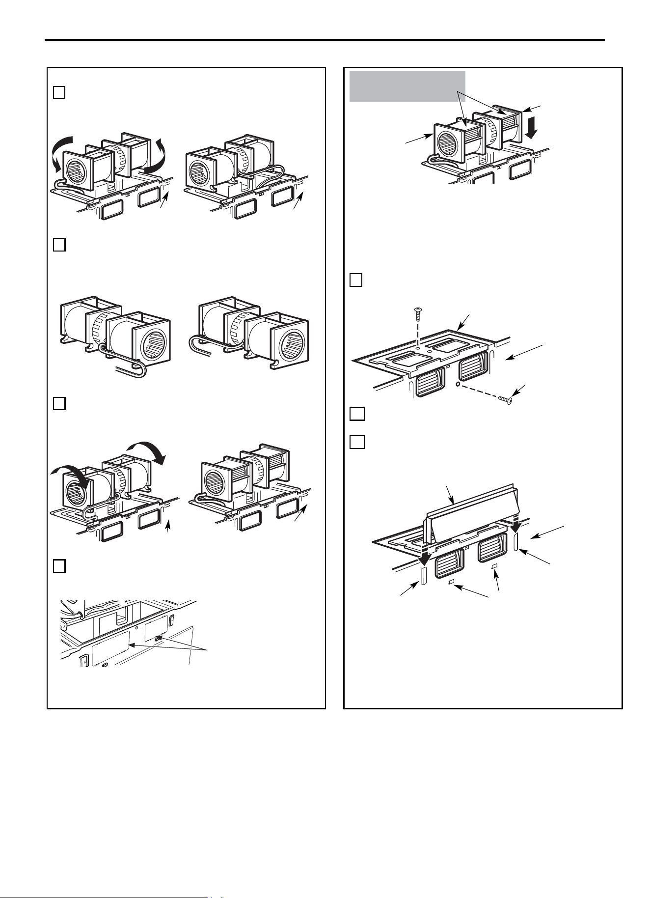
Instructions d’installation
FR-84
L’EXTÉRIEUR (suite)
4 Faire pivoter le ventilateur de 180° en le tournant dans le sens
inverse des aiguilles d’une montre.
5 Retirer délicatement les fils des cannelures.
Acheminer les fils dans les cannelures situées de l’autre coté
du ventilateur.
6 Faire pivoter le ventilateur à 90° de façon à orienter les aubes
du ventilateur vers l’arrière du four à micro-ondes.
7 Déposer les plaques de câblage situées à l’arrière
de l’unité à l’aide de cisailles. (Sur certains
modèles)
MISE EN GARDE : Ne pas tirer ou tendre le
câblage du ventilateur. Vérifier que les fils ne sont
pas écrasés et qu’ils sont correctement fixés.
REMARQUE : Les ouvertures d’échappement du
ventilateur doivent correspondre aux ouvertures
d’échappement situées à l’arrière du four à micro-
ondes.
9 Fixer le ventilateur au micro-ondes à l’aide de la vis
d’origine.
10 Réinstaller la plaque du ventilateur dans sa position d’origine
et la fixer à l’aide de la vis. Vérifier que la vis est bien serrée.
11 Raccorder l’adaptateur d’échappement à l’arrière du four en le
faisant glisser dans les guides situés dans la partie supérieure
centrale du dos du four.
Pousser fermement jusqu’à ce qu’il se bloque dans les languettes
inférieures de verrouillage. Veiller à ce que la charnière de
l’amortisseur soit installée de manière à ce qu’il soit dans le haut et
que l’amortisseur oscille librement.
Dos du four à micro-
ondes
Cisailler les 4 bandes
présentes sur chaque plaque
de
câblage, puis retirer les
câbles métalliques pour la
circulation d
’
air arrière. Veiller
à éliminer les arêtes vives
créées lors du retrait des
plaques de câblage.
Dos du four à
micro
-ondes
Dos du four à
micro
-ondes
Avant rotation
Après rotation
Fils acheminés côté droit
Fils acheminés côté gauche
Avant la nouvelle
Après la nouvelle
Dos du four à
micro
-ondes
Dos du four à
micro
-ondes
Avant rotation
Après rotation
Adaptateur
Guide
Languette de
verrouillage
Dos du four à
micro
-ondes
Guide
Dos du four à
micro
-ondes
Plaque du ventilateur
Moteur du ventilateur
Extrémité B
Extrémité A
APRÈS : Ouvertures des
aubes du ventilateur
orientées vers l’arrière
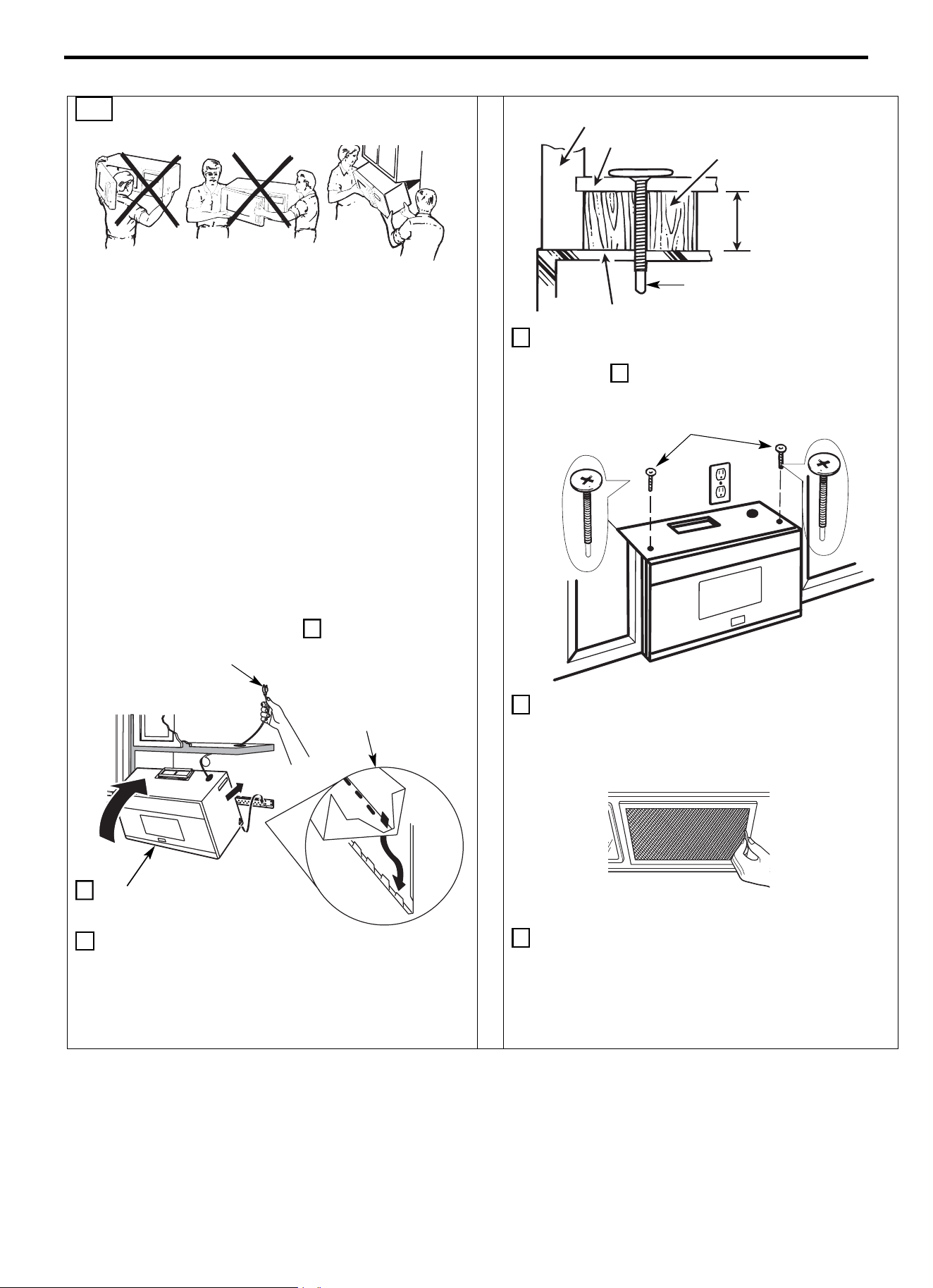
Instructions d’installation
FR-85
B6. MONTAGE DU FOUR À MICRO-
ONDES
POUR FACILITER L’INSTALLATION ET LA SÉCURITÉ
PERSONNELLE, NOUS RECOMMANDONS QUE DEUX
PERSONNES SOIENT PRÉSENTES POUR INSTALLER CE
FOUR À MICRO-ONDES.
REMARQUE IMPORTANTE : Ne pas saisir ou utiliser la
poignée ou la protection thermique pendant l’installation.
Ne pas retirer les entretoises en carton présentes entre la
protection thermique et la porte.
REMARQUE : Si l’armoire est en métal, utiliser le passe-fil en
nylon autour du trou du cordon d’alimentation pour éviter les
coupures au niveau du cordon.
REMARQUE : Nous recommandons d’utiliser des blocs de
remplissage si l’avant de l’armoire dépasse sous l’étagère
inférieure de l’armoire.
REMARQUE IMPORTANTE : En l’absence de blocs de
remplissage, un serrage excessif des vis risque d’endommager
le caisson.
3 Insérer une vis auto-alignante dans le trou central supérieur du
meuble. Fixer temporairement le four en tournant la vis d’au
moins deux tours complets après l’engagement des filetages.
(La vis sera complètement resserrée plus tard.) Vérifier que le
cordon d’alimentation est toujours bien tendu. Veiller à ne
pas coincer le cordon, en particulier, lors du montage au ras
de la base du meuble.
4 Fixer le four à micro-ondes au meuble haut.
5 Insérer 2 vis auto-alignantes à travers les
trous supérieurs extérieurs du meuble.
Effectuer deux tours complets sur chaque
vis.
6 Serrer les deux vis extérieures situées sur le dessus du four à
micro-ondes. (Tout en serrant les vis, maintenir le four à
micro-ondes en place contre la paroi et le meuble haut.)
7 Installer les filtres à graisses. Voir la section Utilisation et
Entretien fourni avec le four à micro-ondes.
REMARQUE : Lors du montage
du four à micro
-
ondes, fileter le
cordon d
’
alimentation à travers le
trou situé au fond du meuble haut.
Le maintenir tendu tout au long des
étapes 1 à 3. Ne pas coincer le
cordon ou soulever le four en tirant
sur le cordon.
1 Soulever le micro-ondes,
l’incliner vers l’avant et
accrocher les fentes du
bord inférieur arrière sur
quatre languettes
inférieures de la plaque
de montage.
2 Faire pivoter l’avant du four
contre la base du meuble.
Avant de l’armoire
Bloc de
remplissage
Étagère inférieure de
l’armoire
Égal à la
profondeur du
renfoncement
de l’armoire
Vis auto-alignante
Dessus du four à micro-ondes
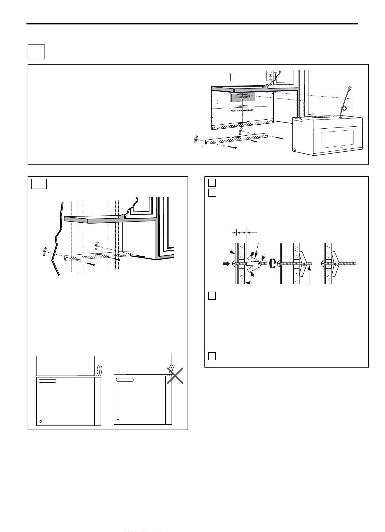
Instructions d’installation
FR-86
C RECIRCULATION (Non ventilé Sans conduit)
VUE D’ENSEMBLE DE L’INSTALLATION
C1. Fixer la plaque de montage à la paroi
C2. Préparer le meuble haut
C3. Contrôler la plaque du ventilateur
C4. Installer le four à micro-ondes
C5. Installer ou remplacer le filtre à charbon
REMARQUES IMPORTANTES :
• Vérifier que les vis fixant le moteur et la plaque du ventilateur
sont correctement serrées lorsqu’elles sont réinstallées. Cette
précaution permet d’éviter les vibrations excessives.
• Vérifier que le câblage du moteur a été correctement disposé et
sécurisé, et que les fils ne sont pas coincés.
C1. FIXER LA PLAQUE DE MONTAGE À
LA PAROI
Fixer la plaque à la paroi à l’aide de boulons à ailettes. Au moins
une vis à bois doit être utilisée pour fixer la plaque à un montant
mural.
REMARQUE : Si la profondeur de l’armoire, y compris les
portes de l’armoire, est supérieure à 13"‘‘,
l’unité doit être espacée du mur à l’aide de
matériaux adéquats supportant 150 livres
(68 kg) pour permettre une
évacuation/admission d’air par le haut
appropriée.
1 Retirer les ailettes des boulons.
2 Insérer les boulons dans la plaque de support à travers les
trous prévus pour pénétrer dans les cloisons sèches, puis
réinstaller les ailettes de ¾” (19 mm) sur chaque boulon.
Utilisation de boulons à ailettes :
3 Poser la plaque de montage contre le mur et insérer les
ailettes dans les trous du mur pour fixer la plaque.
REMARQUE : Avant de serrer les boulons à ailettes et la vis à
bois, vérifier que le bas de la plaque de montage touche le bas de
l’armoire lorsqu’elle est poussée au ras du mur et que la plaque
est correctement centrée sous l’armoire.
MISE EN GARDE : Veiller à ne pas pincer les doigts entre
l’arrière de la plaque de montage et le mur.
4 Serrer tous les boulons. Retirer la plaque du mur pour faciliter
le serrage des boulons.
Armoire
Armoire
Espacement pour les ailettes
supérieur à l’épaisseur de la paroi
Plaque de
montage
Boulon à
ailettes
Extrémité de boulon
Paroi
3/8"TO EDG
E
NOTE: IT IS VERY IMPORTANT TO
READ AND FOLLOWTHE DIRECTIO
N
S
IN THE INSTALLAT
ION INSTRU
CTIO
N
S
BE
FO
RE PR
OCEEDING
WITH T
HIS
REAR W
ALL TEM
PLATE.
This RearWall Template serves to position th
e bottom
mou
nting pl
a
teand to loc
ate the hori
z
onta
l e
x
haust
ou
tlet.
1. Use a level
to
check
that the te
m
plate
i
s po
s
itioned
a
ccu
rately.
2. Locate
and
mark at least ones
tu
d on the
le
ft or
r
ight
s
id
e
of th
e centerl
ine
.
It
is impo
rtan
t to u
se at leas
t one
wood
screw
mo
unted
fir
mly
i
n
a
s
tud
to support the weight
of
the mi
cr
owa
ve.
Mar
k
t
w
o ad
di
tion
al, ev
e
nly
spa
ced
locations
f
or the
s
uppl
ied to
g
gle bol
t
s.
3. Dr
ill
h
ol
es in
the m
ar
ked loc
ations
.
Where th
er
e is
a stud, dr
il
l a 3/16" hole for wood screw
s
. For h
o
les
that
do
n
ot line upwith a
s
tud, d
rill 5/8"
holes for
togg
l
e bolts
.
DO NOT INSTALL
THE
MO
U
NTI
NG PLATE
AT
THISTIME.
4. Re
mov
e th
e templa
te fro
m
the rea
r
wall.
5.Review the Installation Instruction book for your
insta
l
l
atio
n si
tuat
i
on
.
Locate and mark holes to align with holes in the
mountingplate.
IMPORTANT:
LOCATE
AT LEA
ST
O
N
E
STUD
ON EI
T
HER
SID
E O
F
THE CENTERLINE.
MARKTHE LOCATION FOR 2 ADDITIONAL, EVENLY
SPACE
D TO
GGLE
BO
LTS IN THE MOUN
TING
PLATE
AREA
.
Locate and mar
k
holes to align with holes
in t
he
mountingplate.
IMP
ORTANT
:
LOCATE AT LEAST O
NE
STUD
O
N EITHER SID
E OF
TH
E
CENT
E
R
LI
N
E
.
MARK
THE LOCATIO
N
FOR 2 ADDITIONAL, EVENLY
SP
ACED
TOGGLE BOLTS IN
THE MO
UNTING PLATE
AREA
.
Trim the rear wall template alongthe do
tted line.
Trim the rear wall template alongthe dotted line.
12"
4"
Darl
evue
lt
aa la ho
j
a
pa
rac
ons
u
lt
ar
la
versión
enE
spa
ño
l.
Toggle W \ ings
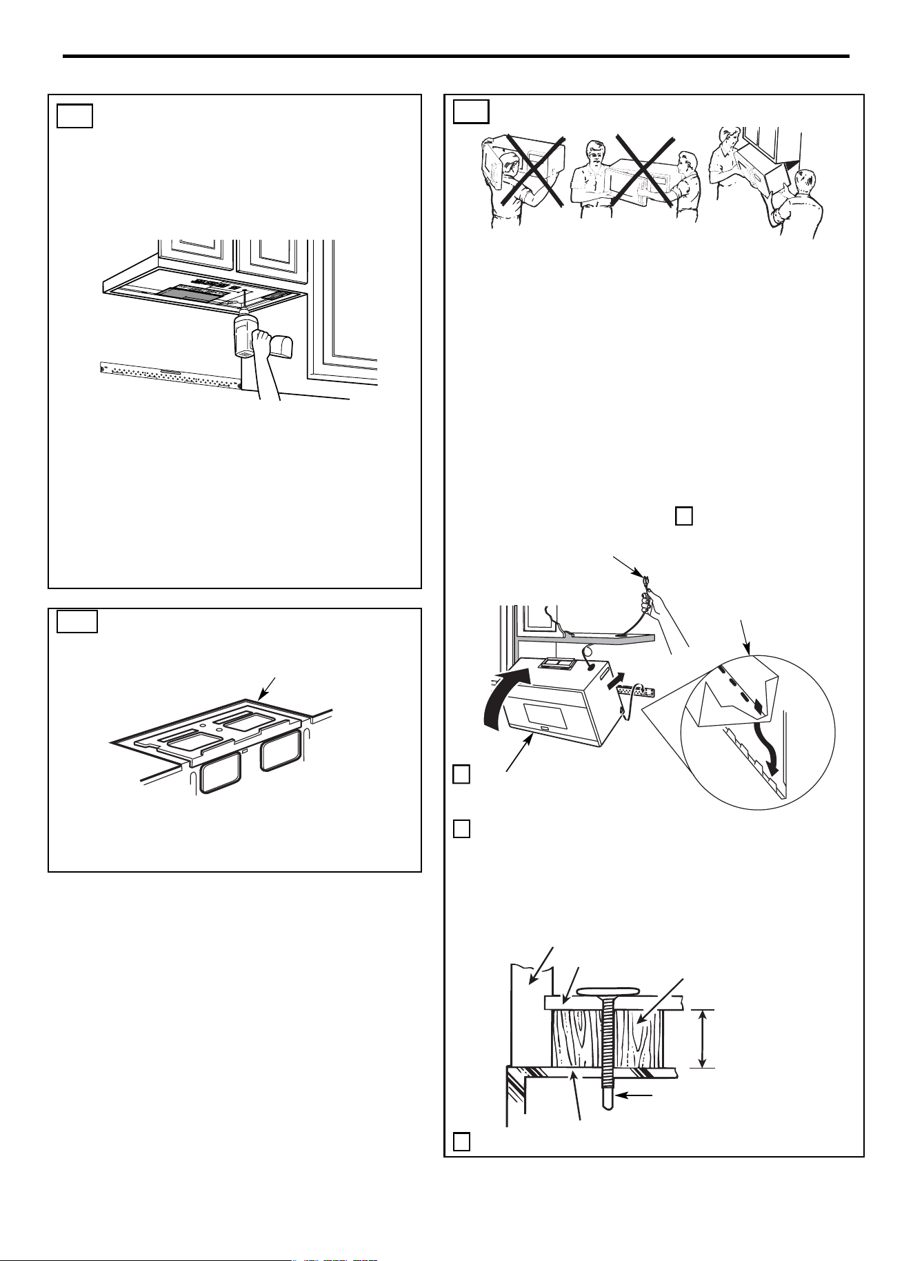
Instructions d’installation
FR-87
C2. PRÉPARATION DU MEUBLE HAUT
A L’AIDE DU GABARIT
RESPECTIF
Il est nécessaire de percer des trous pour les vis du support
supérieur et un trou suffisamment grand pour faire passer le
cordon d’alimentation.
• Lire les instructions relatives au GABARIT MEUBLE
HAUT.
• Le coller sous le meuble haut.
REMARQUE : Ajuster le gabarit supérieur en conséquence si
le four à micro-ondes est espacé du mur en raison de la
profondeur de l’armoire (y compris les portes de l’armoire) de
plus de 13’’.
• Percer les trous en suivant les instructions du GABARIT
MEUBLE HAUT.
MISE EN GARDE : Se munir de lunettes de sécurité au
moment de percer des trous dans le fond de l’armoire.
C4. MONTAGE DU FOUR À MICRO-ONDES
POUR FACILITER L’INSTALLATION ET LA SÉCURITÉ
PERSONNELLE, NOUS RECOMMANDONS QUE DEUX
PERSONNES SOIENT PRÉSENTES POUR INSTALLER CE
FOUR À MICRO-ONDES.
REMARQUE IMPORTANTE : Ne pas saisir ou utiliser la poignée ou la
protection thermique pendant l’installation. Ne pas retirer les
entretoises en carton présentes entre la protection thermique et la porte.
REMARQUE : Si l’armoire est en métal, utiliser le passe-fil en nylon
autour du trou du cordon d’alimentation pour éviter les coupures au niveau
du cordon.
REMARQUE : Nous recommandons d’utiliser des blocs de remplissage si
l’avant de l’armoire dépasse sous l’étagère inférieure de l’armoire.
REMARQUE IMPORTANTE : En l’absence de blocs de remplissage,
un serrage excessif des vis risque d’endommager le caisson.
3 Insérer une vis auto-alignante dans le trou central supérieur du meuble.
Fixer temporairement le four en tournant la vis d’au moins deux tours
complets après l’engagement des filetages. (La vis sera complètement
resserrée plus tard.) Vérifier que le cordon d’alimentation est
toujours bien tendu. Veiller à ne pas coincer le cordon, en
particulier, lors du montage au ras de la base du meuble.
4 Fixer le four à micro-ondes au meuble haut.
C3. CONTRÔLE DE LA PLAQUE DU
VENTILATEUR
• Placer le four à micro-ondes en position verticale, avec le
haut de l’appareil orienté vers le haut.
• Vérifier si la plaque du ventilateur est correctement installée
sur l’appareil.
Avant de
l’armoire
Bloc de
remplissage
Étagère inférieure de
l’armoire
Égal à la
profondeur du
renfoncement
de l’armoire
Vis auto-alignante
Dessus du four à micro-ondes
1 Soulever le micro-ondes,
l’incliner vers l’avant et
accrocher les fentes du
bord inférieur arrière sur
quatre languettes
inférieures de la plaque
de montage.
2 Faire pivoter l’avant du four
contre la base du meuble.
REMARQUE : Lors du montage du
four
à micro-
ondes, fileter le cordon
d
’
alimentation à travers le trou situé
au fond du meuble haut. Le maintenir
tendu tout au long des étapes 1 à 3. Ne
pas coincer le cordon ou soulever le
four en tirant sur le cordon.
Plaque du ventilateur
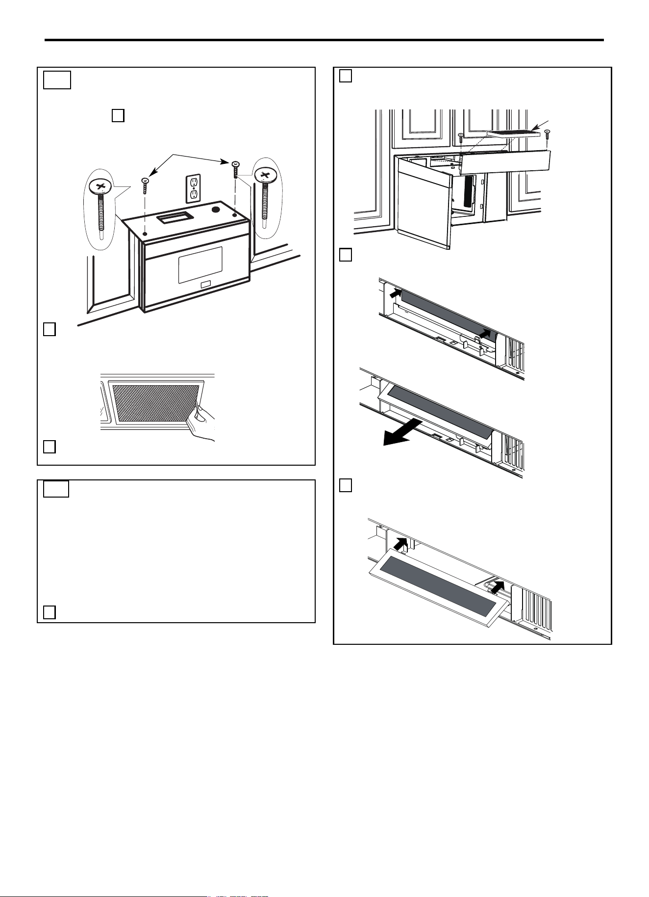
Instructions d’installation
FR-88
C4. MONTAGE DU FOUR À MICRO-
ONDES (suite)
5 Insérer 2 vis auto-alignantes à travers les
trous supérieurs extérieurs du meuble.
Effectuer deux tours complets sur chaque vis.
6 Serrer les deux vis extérieures situées sur le dessus du four à
micro-ondes. (Tout en serrant les vis, maintenir le four à
micro-ondes en place contre la paroi et le meuble haut.)
7 Installer les filtres à graisses. Voir la section Utilisation et
Entretien fourni avec le four à micro-ondes.
2 Ouvrir la porte du four à micro-ondes et déposer les deux vis
de montage du ventilateur situées sur le dessus du four à micro-
ondes à l’aide d’un tournevis cruciforme #1.
3 Retirer le filtre à charbon en poussant le haut du filtre vers
l’intérieur, puis le tirer vers l’avant de l’appareil.
4 Faire glisser le haut du nouveau filtre à charbon dans la partie
supérieure de la cavité du filtre.
C5. INSTALLER OU REMPLACER LE
FILTRE À CHARBON
(sur certains modèles)
REMARQUE : Le filtre à charbon est installé en usine sur certains
modèles. Se reporter à la section Utilisation et entretien pour savoir
si le vôtre est installé en usine et pour obtenir des informations sur
le remplacement.
Pour les modèles sans trappe d’accès du filtre de recirculation,
suivre ces étapes pour remplacer ou installer un filtre à charbon.
1 Débrancher le four à micro-ondes ou couper le courant.
Filtre à
charbon
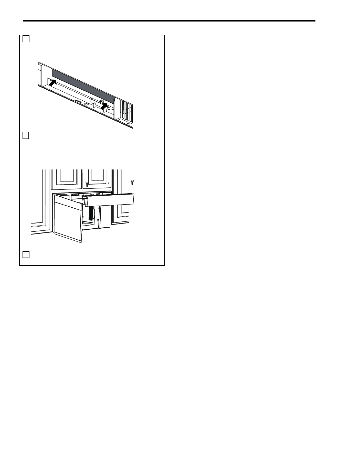
Instructions d’installation
FR-89
5
Appuyer sur le bas du filtre à charbon pour l’installer dans la
position correcte.
6 Saisir le ventilateur par le bas et le remettre en place en le
faisant glisser. Pousser le haut du ventilateur, puis le faire
glisser dans sa position définitive. Réinstaller les deux vis de
montage du ventilateur situées sur le dessus du four à micro-
ondes à l’aide d’un tournevis cruciforme #1.
7 Fermer la porte du micro-ondes. Brancher le four à micro-
ondes ou rétablir le courant.
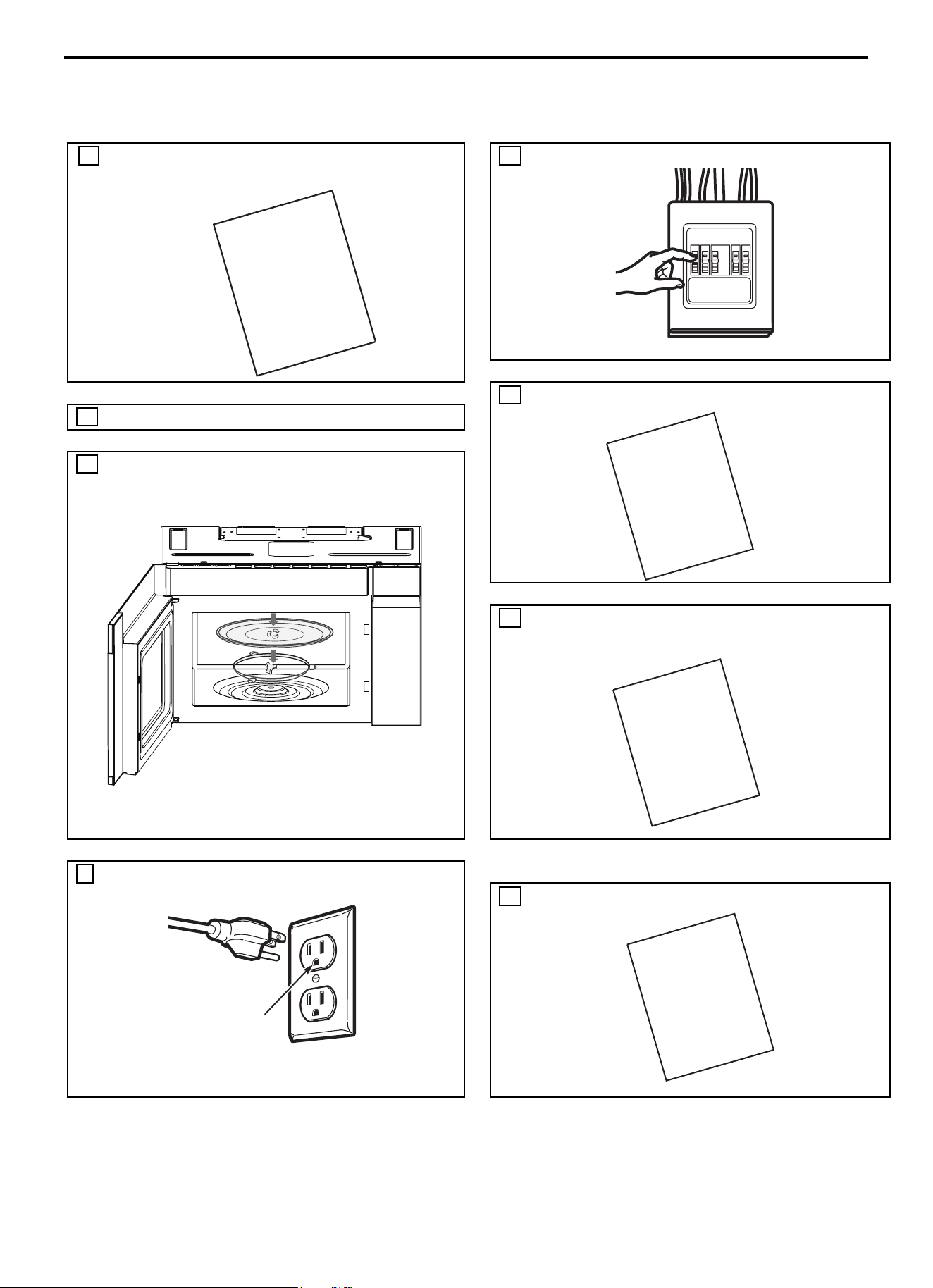
Instructions d’installation
FR-90
AVANT D’UTILISER LE FOUR A MICRO-ONDES
1. S’assurer que le four à micro-ondes a été installé
conformément aux instructions.
5. Réinstaller le fusible de l’habitation ou réactiver le
disjoncteur.
6.
Lire le manuel UTILISATION ET ENTRETIEN.
2. Retirer tout le matériel d’emballage du four à micro-ondes
3. Installer l’anneau de roulement et le plateau en verre dans la
cavité.
7. CONSERVER LES INSTRUCTIONS D’INSTALLATION
À L’INTENTION DE L’INSPECTION LOCALE.
4. Brancher le cordon d’alimentation dans une prise électrique
séparée et dédiée de 15 à 20 ampères.
8.
REMPLIR LA FICHE D’ENREGISTREMENT DU
PRODUIT ET L’ENVOYER.
S’assurer qu’une mise à
la terre conforme est
présente avant toute
utilisation.
INSTALLATION
INSTRUCTIONS
MANUAL
USE
|++&=
CARE
&
INSTALLATION
INSTRUCTIONS
PRODUCT
CARD
REGISTRATION

SERVICE CLIENTÈLE
Pour toute information sur la garantie et demande de service, contactez-nous:
https://us.bertazzoni.com/more/supportAux États-Unis :
Au Canada: https://ca.bertazzoni.com/more/support