
TABLE OF CONTENTS
1. SAFETY REGULATIONS ............................................... 2
Regulations for using the machine safely
2. IDENTIFICATION OF THE MACHINE
AND COMPONENTS ...................................................... 3
Explanations on how to identify the machine
and its main components
3. UNPACKING AND ASSEMBLY ...................................... 4
Explanations on how to remove the packing and on how to
assemble separated parts
4. CONTROLS AND INSTRUMENTS ................................. 7
Position and functions of all the controls
5. HOW TO USE THE MACHINE ....................................... 9
Provides indications for working efficiently and safely
5.1 Safety recommendations .......................................... 9
5.2 Why the safety devices cut in ................................... 9
5.3 Preliminary operations before starting work ........... 10
5.4 Using the machine .................................................. 11
5.5 Using on slopes ...................................................... 14
5.6 Transporting ........................................................... 14
5.7 Advice on how to obtain a good cut ....................... 14
5.8
Summary of the main operations to be carried out
in various condition
.................................................. 15
6. MAINTENANCE ............................................................ 15
All the information for maintaining the machine
in peak efficiency
6.1 Safety recommendations ........................................ 15
6.2 Routine maintenance .............................................. 15
6.3 Checks and adjustments ........................................ 16
6.4 Dismantling and renewing parts ............................. 19
7. ENVIRONMENTAL PROTECTION ............................... 22
It gives advice on machine use and respecting
the environment
8. TROUBLESHOOTING .................................................. 23
A help in quickly resolving any problems
9. ACCESSORIES ON REQUEST .................................... 24
A description of the accessories available
for particular types of work
10. SPECIFICATIONS ......................................................... 25
A summary of the main specifications of your machine
11. ALPHABETICAL INDEX ............................................... 26
Where information can be found
MAJORS HONDA DISTRIBUTOR ADDRESSES ........... i
DECLARATION OF CONFORMITY ................................ ii
INTRODUCTION
Dear Customer,
Thank you for having chosen one of our products. We hope that you will get
complete satisfaction from using your new lawn-tractor and that it will fully
meet all your expectations.
This manual has been compiled in order that you may get to know your ma-
chine and to be able to use it safely and efficiently. Donʼt forget that it forms
an integral part of the machine, so keep it handy so that it can be consulted
at any time, and pass it on to the purchaser if you resell the machine.
This new machine of yours has been designed and made in line with current
regulations, and is safe and reliable if used for cutting and collecting grass
exactly following the instructions given in this manual (proper usage). Using
the machine in any other way or ignoring the instructions for safe usage,
maintenance and repair is considered "incorrect usage" ( 5.1) which will
invalidate the guarantee, and the manufacturer will decline all responsibility,
placing the blame with the user for damage or injury to himself or others in
such cases.
Since the product is continually being improved, you may find slight diffe -
rences between your machine and the descriptions contained in this man-
ual. Certain modifications can be made to the machine without prior warn-
ing and without the obligation to update the manual, although the essential
safety and function characteristics will remain unaltered. In case of any
doubts, do not hesitate to contact your Dealer. And now enjoy your work!
After-sales Service
This manual gives all the necessary instructions for using the machine and
the basic maintenance that may be carried out by the user.
Contact your Dealer for operations not described in this manual.
1EN
OPERATORʼS MANUAL
ORIGINAL INSTRUCTION
HF2315 • HF2417 • HF2620
Lawn mower
Honda France Manufacturing S.A.S.
Pôle 45 - Rue des Châtaigniers - 45140 ORMES - FRANCE
All rights reserved
HOW TO READ THE MANUAL
Some paragraphs in the manual containing information of particular impor-
tance for safety and operation are highlighted at various levels of emphasis,
and signify the following:
or These give details or further
information on what has already been said, and aim to prevent damage
to the machine.
Non-observance will result in the risk of injury to
oneself or others.
Non-observance will result in the risk of serious in-
jury or death to oneself or others.
This manual describes various versions of the machine, which mainly differ
in:
– type of transmission: with mechanical gear-change or with hydrostatic con-
tinuous speed adjustment;
– blade engagement system, manual, pneumatic or electromagnetic clutch;
– special equipment and/or accessories.
The symbol highlights all differences in usage and is followed by the
indication of the version to which it refers.
The symbol “ ” makes a reference to another part of the manual where fur-
ther information or clarification can be found.
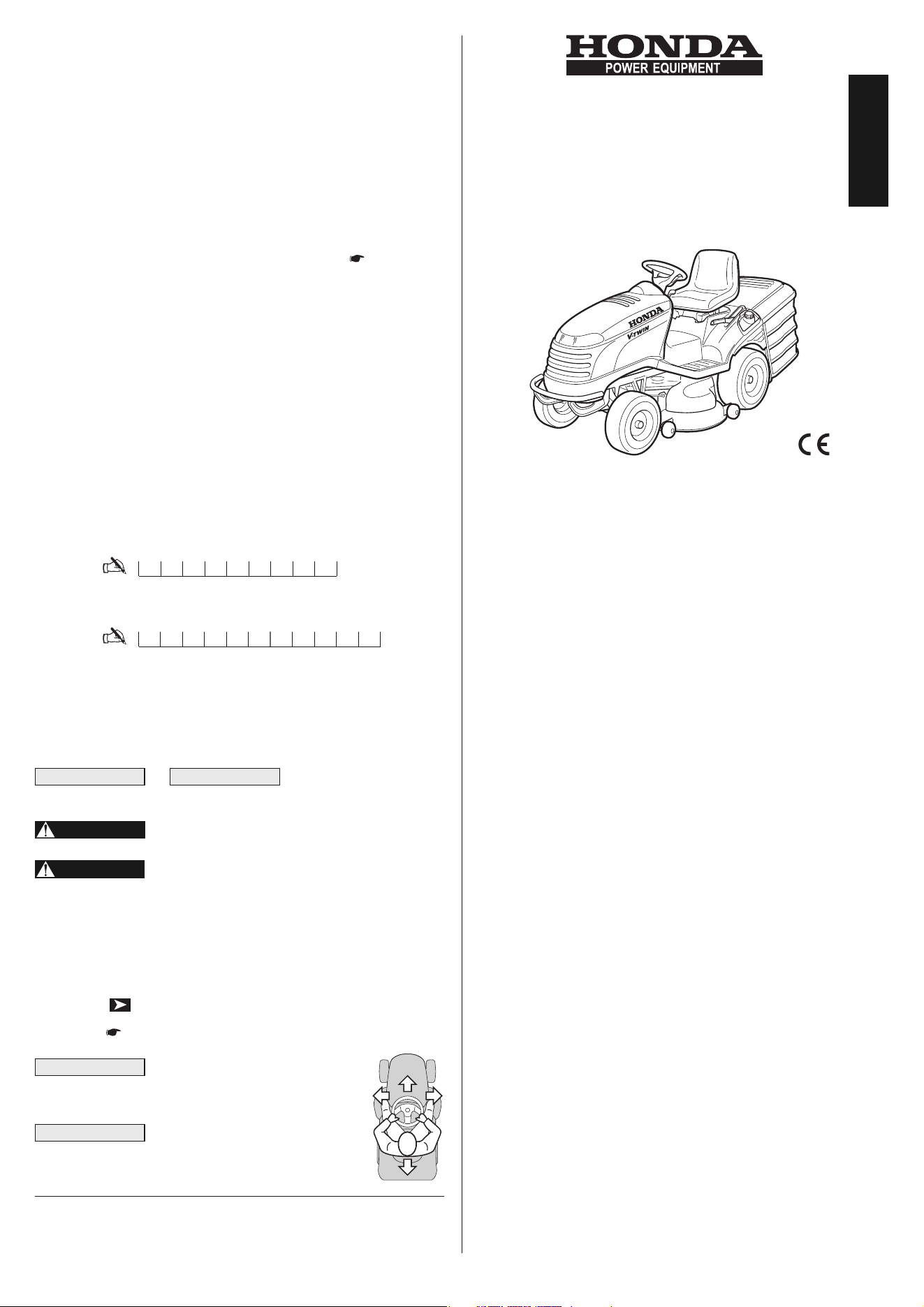
Whenever a reference is made to a po-
sition on the machine “front”, “back”, “left” or “right” hand
side, this is determined by facing the direction of forward
travel.
For all usage and maintenance opera-
tions on the battery which are not described in this manual,
consult the relevant manual which form an integral part of
all the documentation supplied with the machine.
IMPORTANT
NOTE
DANGER!
WARNING!
IMPORTANTNOTE
ENGLISH
Note your
machine serial number here
Write your
machineʼs model here
HF2______
MA_________

1. SAFETY REGULATIONS
1.1 GENERAL SAFETY REGULATIONS
Read carefully before using the machine.
A) TRAINING
1) Read the instructions carefully. Be familiar with the controls
and the proper use of the equipment.
2) Never allow children or people unfamiliar with these instructions
to use the lawnmower. Local regulations can restrict the age of the
operator.
3) Never mow while people, especially children, or pets are
nearby.
4) Keep in mind that the operator or user is responsible for acci-
dents or hazards occurring to other people or their property.
5) Do not carry passengers.
6) All drivers should seek and obtain professional and practical
instruction. Such instruction should emphasise:
– the need for care and concentration when working with ride-on
machines;
– control of a ride-on machine sliding on a slope will not be
regained by the application of the brake.
The main reasons for loss of control are:
– insufficient wheel grip;
– being driven too fast;
– inadequate braking;
– the type of machine is unsuitable for its task;
– lack of awareness of the effect of ground conditions, especial-
ly slopes;
– incorrect hitching and load distribution.
B) PREPARATION
1) While mowing, always wear substantial footwear and long
trousers. Do not operate the equipment when barefoot or wearing
open sandals.
2) Thoroughly inspect the area where the equipment is to be used
and remove all objects which can be thrown by the machine.
3) DANGER! Petrol is highly flammable:
– store fuel in containers specifically designed for this purpose;
– refuel outdoors only and do not smoke while refuelling;
– add fuel before starting the engine. Never remove the cap of
the fuel tank or add petrol while the engine is running or
when the engine is hot;
– If petrol is spilled, do not attempt to start the engine but move the
machine away from the area of spillage and avoid creating any
source of ignition until the petrol vapours have dissipated;
– replace all fuel tank and container caps securely.
4) Replace faulty silencers.
5) Before using, always visually inspect to see that the blades,
blade bolts and cutter assembly are not worn or damaged. Replace
worn or damaged blades and bolts in sets to preserve balance.
6) On multi-bladed machines, take care as rotating one blade can
cause other blades to rotate.
C) OPERATION
1) Do not operate the engine in a confined space where dan gerous
carbon monoxide fumes can collect.
2) Mow only in daylight or good artificial light.
3) Before attempting to start the engine, disengage all blade
attachment clutches and shift into neutral.
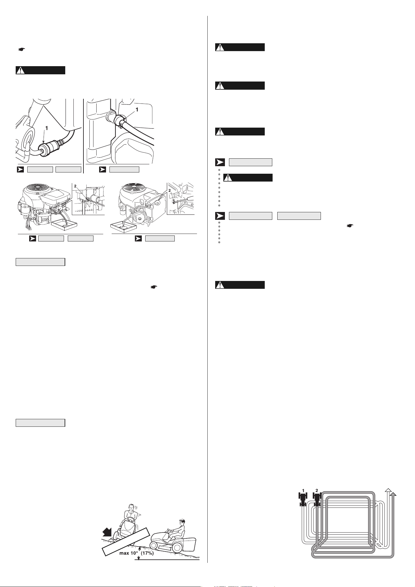
4) Do not use on slopes of more than 10° (17%).
5) Remember there is no such thing as a “safe” slope. Travel on
grass slopes requires particular care. To guard against overturning:
– do not stop or start suddenly when going up or downhill;
– engage the clutch slowly and always keep the machine in gear,
WARNING!
especially when travelling downhill;
– machine speeds should be kept low on slopes and during tight
turns;
– stay alert for humps and hollows and other hidden hazards;
– never mow across the face of the slope.
6) Use care when pulling loads or using heavy equipment:
– use only approved drawbar hitch points;
– limit loads to those you can safely control;
– do not turn sharply. Use care when reversing;
7) Stop the blades rotating before crossing surfaces other than
grass.
8) Never operate the machine with defective guards, or with-
out safety protective devices in place.
9) Do not change the engine governor settings or overspeed
the engine. Operating the engine at excessive speed can increase
the hazard of personal injury.
10) Before leaving the operatorʼs position:
– disengage the power take-off and lower the attachments;
– change into neutral and set the parking brake;
– stop the engine and remove the key.
11) Disengage drive to attachments, stop the engine and re mo -
ve the ignition key:
– before clearing blockages or unclogging chutes;
– before cleaning, checking or working on the machine;
– after striking a foreign object. Inspect the machine for damage
and make repairs before restarting and operating the equipment;
– If the machine starts to vibrate abnormally (check immediately).
12) Disengage drive to blades when transporting or not in use.
13) Stop the engine and disengage drive to the attachment:
– before refuelling;
– before removing the grass catcher.
14) Reduce the throttle setting during engine run-out and, if the en-
gine is provided with a shut-off valve, turn the fuel off at the conclu-
sion of mowing.
15) The usage of accessories different from those recommended by
Honda may cause damage to the machine that is not covered by the
warranty.
D) MAINTENANCE AND STORAGE
1) Keep all nuts, bolts and screws tight to be sure the equipment is
in safe working condition.
2) Never store the equipment with petrol in the tank inside a build-
ing where fumes may reach an open flame or spark.
3) Allow the engine to cool before storing in any enclosure.
4) To reduce the fire hazard, keep the engine, silencer, battery com-
partment and petrol storage area free of grass, leaves, or excessive
grease.
5) Check the grass catcher frequently for wear or deterioration.
6) Replace worn or damaged parts for safety.
7) If the fuel tank has to be drained, this should be done outdoors.
8) On multi-bladed machines, take care as rotating one blade can
cause other blades to rotate.
9) When the machine is to be stored or left unattended, lower the
cutting deck.
2EN
1.3 REGULATIONS FOR TOWING
A kit for towing a small trailer is available on request. This accessory
is to be fitted as per the instructions pro-
vided.
When using, do not exceed the recom-
mended drawbar loads stated on the de-
cal and follow the safety instructions,
( 1.2, C-6).
2. IDENTIFICATION OF THE MACHINE
AND COMPONENTS
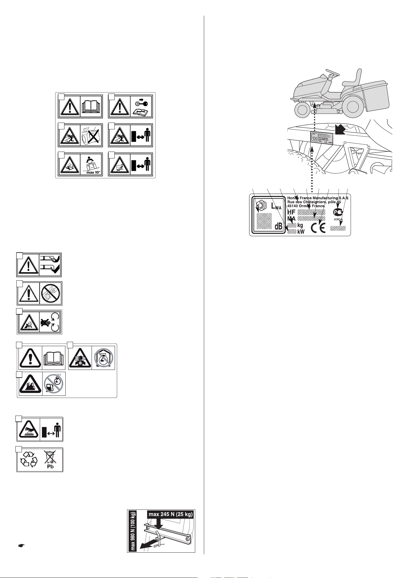
2.1 IDENTIFICATION OF THE MACHINE
The plate located on the
left side of the main frame
has the essential data of
each machine.
The serial number (5)
must be quoted when you
require technical assis-
tance or spare parts.
1. Acoustic power level according to directives 2000/14/EC,
2005/88/EC
2. Conformity mark according to directives 98/37/EC
(2006/42/EC, 2005/88/EC, 2004/108/EC
2a. Russian Comformity Mark
3. Year of manufacture
4. Type of machine
5. Serial number
6. Weight in kg
7. Name and address of Manufacturer
8. Engine nominal power (at 2800 rpm).
1.2 SAFETY DECALS
Your machine must be used with care. Therefore, decals have been
placed on the machine, to remind you pictorially of the main pre-
cautions to take during use. These decals are to be considered an
integral part of the machine.
If a decal should fall off or become illegible, contact your Dealer to
replace it. Their meaning is explained below.
3EN
HOW TO RECOGNIZE YOUR MACHINE
Preparation, use and maintenance of a range of machines with many
differing features are described in this manual. It is therefore im-
portant to clearly identify your machineʼs model in order to following
all of the information regarding it.
Your machineʼs model is indicated on the “identification label” in point
4 and is composed of a series of letters and numbers.
In the following pages of this manual, the model or models to which
operations refer are indicated beforehand. The absence of any in-
dication means it is valid for all models.
1 = Warning: Read the instructions before operating this machine.
2 = Warning: Disconnect the ignition key and read the instructions before carrying out
any repair or maintenance work.
3 = Danger! Ejected objects: Do not operate without either the stone-guard or
grass-catcher in place.
4 = Danger! Ejected objects: Keep bystanders away.
5 = Danger! Machine rollover: Do not use this machine on slopes greater then 10°.
6 = Danger! Dismemberment: Make sure that children stay clear of the machine all
the time when engine is running.
7 = Danger of cutting yourself. Blades in movement. Do
not put hands or feet near or under the opening of the cut-
ting plate.
8 = Warning: Do not manipulate the mi croswitch.
9 = Avoid injury from getting caught in belt: Do not oper-
ate the machine without shields in place. Stay clear of
belts.
1
3
5
2
4
6
7
8
10
12
11
13
14
9
10 = Warning: Read the instruc-
tions before operating this
machine.
11 = Warning: The engine emits
toxic carbon monoxide. Do
not run in an enclosed area.
12 = Warning! Petrol is highly
flam mable. Stop the engine
before refueling.
13 = Warning: the muffler becomes very hot during opera-
tion and remains hot for a while after stopping the en-
gine.
14 = This is a recyclable product. It contains lead. Do not
discard it in the environment and dispose of in compli-
ance with the laws in force.
1 8 6 7 4 5 2 2a 3
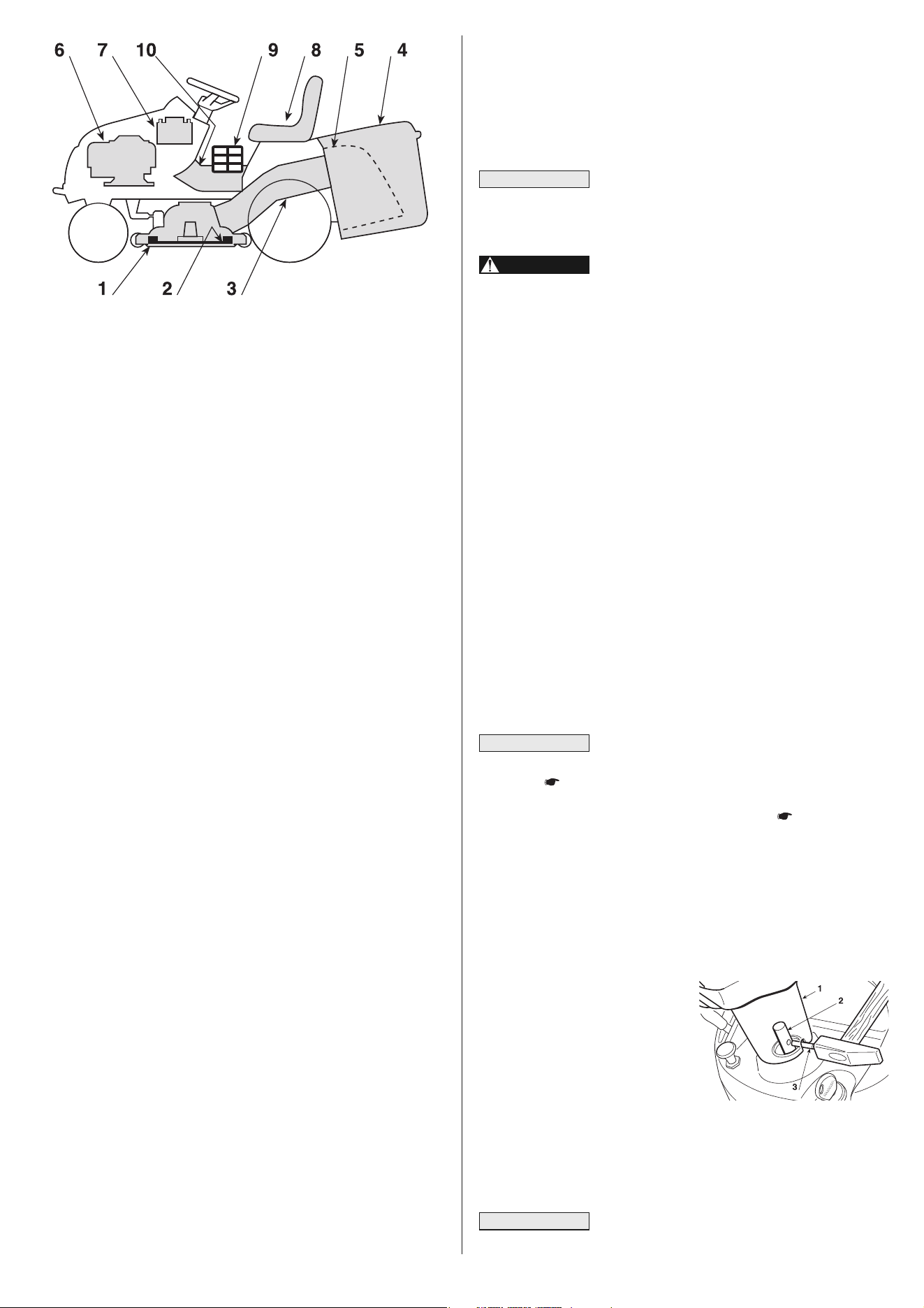
2.2 IDENTIFICATION OF MAIN COMPONENTS
Various main components can be seen on the machine, and these
have the following functions:
1. Cutting deck: this is the guard enclosing the rotating blades.
2. Blades: these are what cut the grass. The wings at the ends
help convey the cut grass towards the collector channel.
3. Collector channel: this is the part connecting the cutting deck
to the grass-catcher.
4. Grass-catcher: as well as collecting the grass cuttings, this is
also a safety element in that it stops any objects drawn up by
the blades from being thrown outside of the machine.
5. Stone-guard or deflector (available as optional part): this
can be fitted in place of the grass-catcher and prevents objects
drawn up by the blades from being thrown outside of the ma-
chine.
6. Engine: this moves the blades and drives the wheels.
7. Battery: provides the energy for starting the engine. Its spe ci -
fi cations and regulations for use are described in a specific man-
ual.
8. Driver seat: this is where the machine operator sits. It has a
sensor for detecting the presence of the operator which is a sa -
fety device.
9. Decals for regulations and safety: give reminders on the
main provisions for working safely, each of which is explained
in chapter 1.
10. Inspection hatch: for access to make several adjustments.
3. UNPACKING AND ASSEMBLY
For storage and transport reasons, some components of the
machine are not directly installed in the factory, but have to be
assembled after their removal from the packing. Final assembly is
carried out by following these simple instructions.
The machine is supplied without engine oil or
fuel. Before starting up the engine, fill with oil and fuel following the
instructions.
Unpacking and completing the assembly
should be done on a flat and stable surface, with enough
space for machine handling and its packaging, always ma k-
ing use of suitable equipment.
3.1 UNPACKING
When unpacking the machine, take care to gather all individual parts
and fittings, and do not damage the cutting deck when ta king the ma-
chine off the base pallet.
The packing contents:
– the machine;
– the steering wheel;
– the seat;
– the front bumper (if fitted);
– the grass-catcher brackets;
– the grass-catcher components;
– the battery charger;
– an envelope containing:
– the operatorʼs manuals and documents,
– the nuts and bolts including a pin for blocking the steering
wheel,
– 2 starter keys and a spare 10 A fuse.
To prevent damaging the cutting deck when get-
ting the ma chine down from the pallet, take it to the maximum
height ( 4.6) and be very careful. In the hydrostatic drive mo -
dels, to get the machine off the pallet and to move it more easily,
put the drive disengage lever in position «B» ( 4.34).
Disposal of the packaging should be done in accordance with the
local regulations in force.
FITTING THE STEERING WHEEL
Put the machine on a flat surface
and straighten up the front wheels.
Fit the steering wheel (1) onto the
protruding shaft (2) with the spo -
kes directed towards the seat.
Line up the hole in the steering wheel hub with the hole in the shaft
and insert the pin supplied (3) using a hammer, ensuring that the end
comes completely through to the opposite side.
To avoid damaging the steering wheel, use a
punch of the same size to push the pin in the last part.
NOTE
IMPORTANT
WARNING!
IMPORTANT
4EN
To prevent the safety device in the electronics
card from cutting in, never start the engine until the battery is fully
charged!
Battery acid is corrosive and a pollutant.
When handling, use protective gloves and dispose of prop-
erly following current regulations.
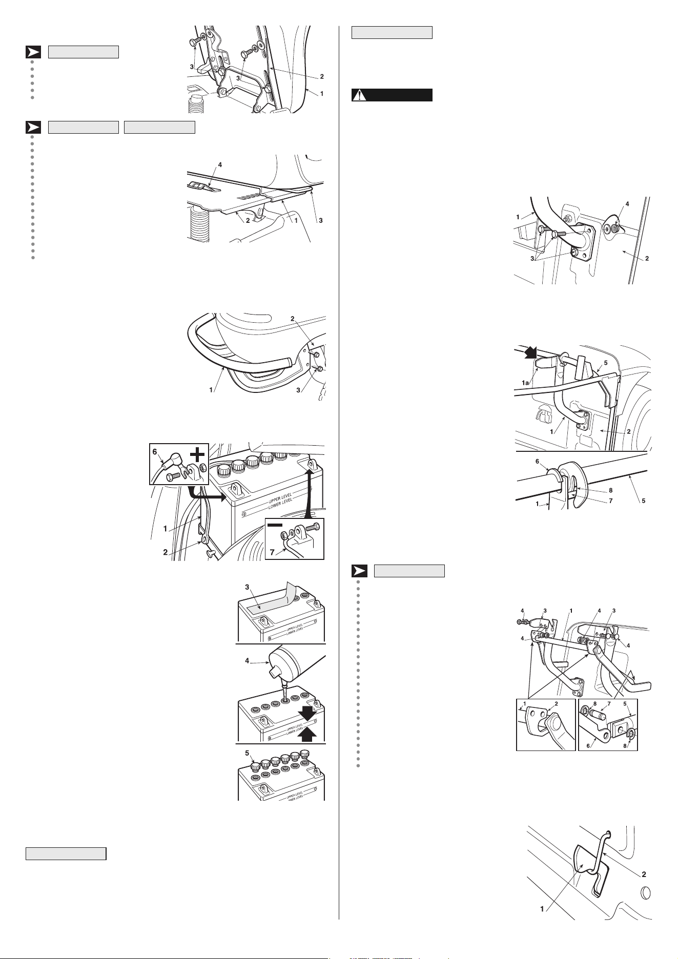
3.6 GRASS-CATCHER SUPPORT ASSEMBLY
Fit the two brackets (1) on the rear
plate (2), using for each bracket
three screws (3) which are sup-
plied, as shown, without fully tight-
ening the nuts (4).
The supports (1) must be mounted
so that the wings (1a) are turned
inwards.
Hook the upper part of the grass-catcher frame (5) onto the bra ckets
and centre it up with the rear plate (2).
Adjust the position of the two
brackets (1) to the stop (6) so that,
when turning the grass-catcher
frame, the pin (7) slots into the
seat (8) correctly.
Check again that the frame (5) is
properly centred with the rear plate
(2) and that it rotates correctly, as
shown above, and then fully
tighten the screws (3) and the nuts
(4).
3.7 ASSEMBLING THE LEVERS FOR TIPPING
THE GRASS-CATCHER
Position the lever axle (1) in the
notch of the two plates (2) and
attach them on the internal side
of the grass-catcher supports
(3), using the included screws
(4) in the sequence shown.
Connect the end of the rod (5)
of the lifting piston to the lever
(6) with the pin (7) and attach
the two snap rings (8).
Before attaching the grass-
catcher to its supports, make
sure that the tipping lever
moves properly.
3.8 REMOVAL OF THE STOP FROM THE HOOKING PAWL OF
THE GRASS-CATCHER
For transport purposes, the pawl (1)
hooking the grass-catcher is held
onto the rear plate by a stop (2). This
stop must be removed before fitting
the grass-catcher brackets, and is not
to be subsequently used.
HF2•••HT•
WARNING!
IMPORTANT
3.3 FITTING THE SEAT
Mount the seat (1) on the
plate (2) using the screws (3).
Raise the adjustment lever (3)
and fit the seat (1) in the slide
(2), introducing it from the stee r-
ing wheelʼs side, till the seat en-
gages in one of the 6 positions.
At this point the seat is engaged
and cannot be removed unless
the lever (4) is pressed, freeing
it from its retainer.
FRONT BUMPER ASSEMBLY (if fitted)
Fit the front bumper (1) on the
lower part of the frame (2) using
the four screws (3).
3.5 CONNECTING THE BATTERY
The battery (1) is situated
behind the engine and is
held in place by an elastic
strap (2). Unhook the
elastic strap (2), remove
the battery and its protec-
tive cover (3) and pour
the electrolytic solution
(4) (Acid not supplied:
specific gravity 1.280 or
31.5° Baumé) until the in-
dicated level is reached, distributing it evenly
among the six elements.
Close the six caps (5) which are included and
begin charging the battery.
The elastic strap (2) shoud be placed behind
the filling caps (5) of the battery.
Connect the red cable (6) to first the positive
terminal (+) then the black cable (7) to the
negative terminal (–) using the supplied
screws as indicated.
Grease the terminals with silicon grease,
making sure that the protective cap of the
red cable (6) is positioned correctly.
After having activated the battery, continue
charging it completely. Contact your Dealer who has all of the
proper equipment available. The battery charger supplied is NOT
able to carry out the first charging of the battery after it has been
activated.
IMPORTANT
HF2•••◊M• HF2•••◊T•
HF2•••◊B•
5EN
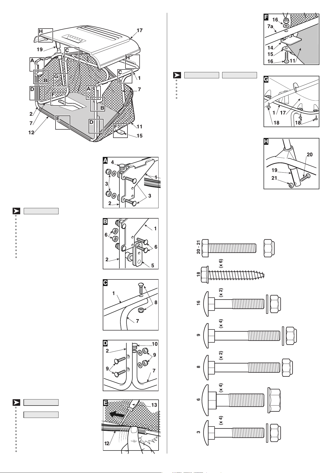
3.9 GRASS-CATCHER ASSEMBLY
A) Join the upper part of the frame (1)
to the front component (2) using the
supplied screws and nuts (3) as
shown. Fit the two rubber caps (4) into
the holes in the tube of front frame (2).
B) Before fully tightening the nuts
(3), insert the two supports (5) be-
tween the plates of the upper frame
(1) with the rollers turned inwards.
Fasten them with the screws and
nuts (6) and then fully tighten the
nuts (3).
C-D) Attach the two side elements
(7), using the screws and nuts (8 and
9) as shown. Fit the two rubber caps
(10) into the holes in the two side ele-
ments (7).
E) Insert the frame in the canvas cover
(11) making sure it is correctly posi-
tioned on the base perimeter. Hook the
plastic profiles (12) onto the frame
tubes with the aid of a screw-driver
(13).
F) Place the plate (14) between the
canvas and the lower part of the
frameʼs right side element (7a), lin-
ing up the holes.
HF2•••HM•
HF2•••SB•
HF2•••HT•
F) Attach the stiffening bar (15) under
the frame with screws and nuts (16)
keeping the flat part turned towards
the canvas.
G) Using the six screws (18), attach
the cover (17) to the frameʼs upper part
(1).
H) Insert the emptying lever (19)
in its position and put in the limit
stop screw (20) with its nut (21).
HF2•••SB• HF2•••HM•
6EN
C
L
A
K
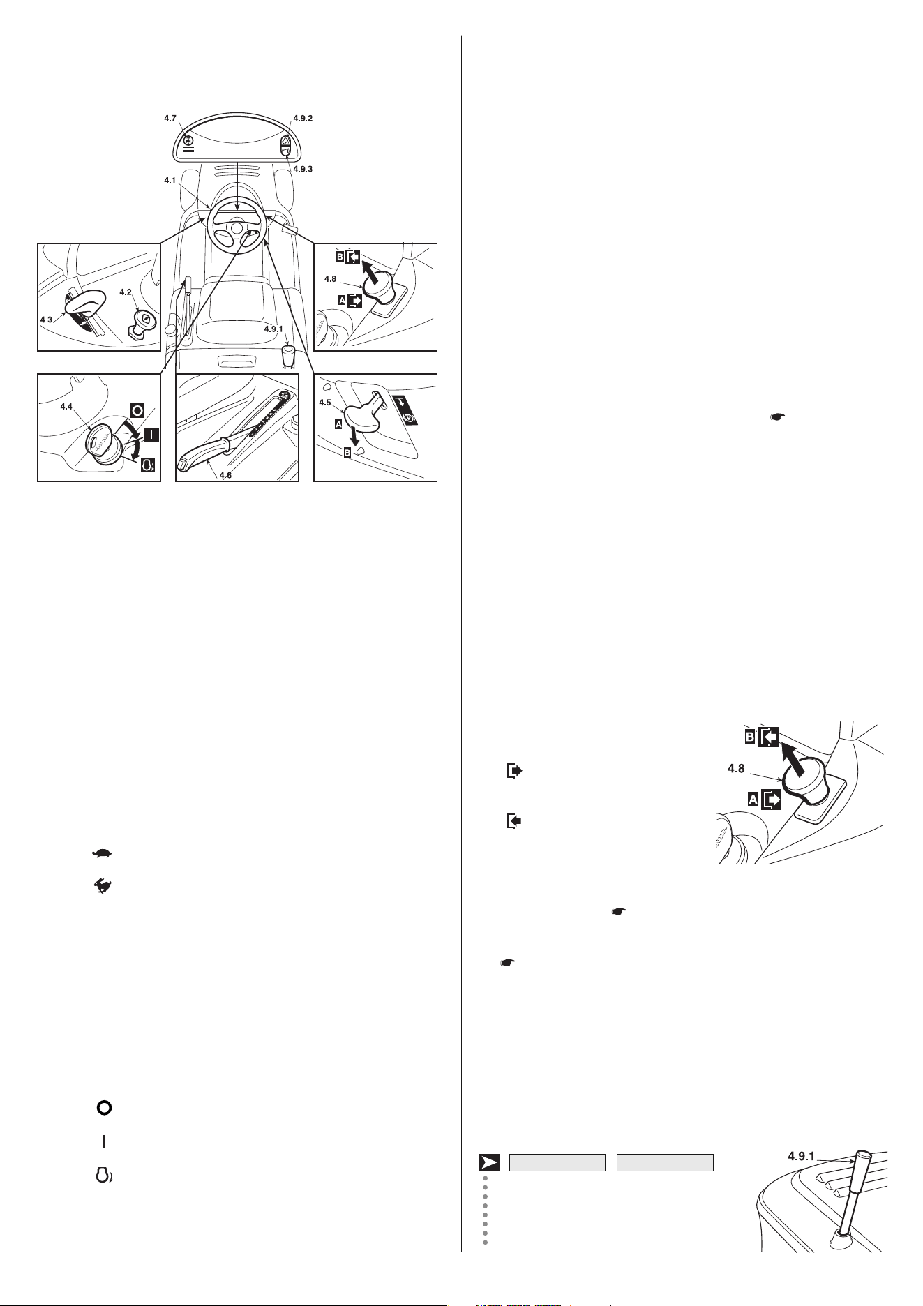
4.5 PARKING BRAKE LEVER
This lever is to stop the machine from moving when it has been
parked. There are two positions:
«A» = Brake off
«B» = Brake engaged
– The brake is engaged by fully pressing the pedal (4.21 or 4.31)
and moving the lever to position «B». When you take your foot off
the pedal it will be blocked in the down position.
– In models which include it, a pilot lamp will warn that the “brake
is engaged” (4.10.d).
– To disengage the parking brake, press the pedal (4.21 or 4.31).
The lever will return to position «A».
4.6 CUTTING HEIGHT ADJUSTING LEVER
There are seven positions for this lever, shown as «1» to «7» on the
label, which correspond to just as many cutting heights. Their val-
ues are indicated in the “Specifications table” ( Chapter 10).
– To go from one height to another, press the release button at the
end of the lever.
4.7 PUSH-BUTTON FOR REVERSE MOWING
By keeping the push-button pressed, it is possible to engage the re-
verse gear and go backwards even with the blades engaged, with-
out causing the engine to stop.
4.8 BLADE ENGAGEMENT AND BRAKE CONTROL
The mushroom switch is for engaging
the blades by an electromagnetic
clutch:
«A» Pressed
= Blades disengaged
«B» Pulled
= Blades engaged
– The “Blades engaged” condition is indicated by a pilot lamp (ex-
cept SB• models)( 4.10.c).
– If the blades are engaged when safety conditions have not been
complied with, the engine shuts down and cannot be restarted
( 5.2).
– On disengaging the blades (position «A»), a brake is simultane-
ously activated which stops their rotation in few seconds.
– It is possible to engage the blades in reverse only by pressing
push-button 4.7.
4.9 CONTROL FOR TIPPING GRASS-CATCHER
The grass-catcher may be tipped to
empty by pulling the lever (4.9.1), which
can be extracted from its housing.
HF2•••SB• HF2•••HM•
4. CONTROLS
AND INSTRUMENTS
4.1 STEERING WHEEL
Turns the front wheels.
4.2 CHOKE CONTROL
This enriches the mixture so must only be used for the time neces-
sary when starting from cold.
4.3 ACCELERATOR LEVER
Regulates the engine's r.p.m. The positions are indicated on the
plate and correspond to:
«SLOW» for minimum engine speed
«FAST» for maximum engine speed
– When moving from one area to another, put the lever in a posi-
tion between «SLOW» and «FAST».
– When cutting, go to the «FAST» position.
4.4 KEY IGNITION SWITCH
This key operated control has three positions:
«OFF» everything is switched off;
«ON» activates all parts;
«START» engages the starter motor.
On being released at the «START» position, the key will automati-
cally return to «ON».
7EN
The grass-catcher may be emptied by
pressing the push-button (4.9.2), keep-
ing it pressed until the control motor
stops.
The grass-catcher returns to the working
position by pressing the push-button
(4.9.3), keeping it pressed until the pawl
hooks into place and the control motor
stops.
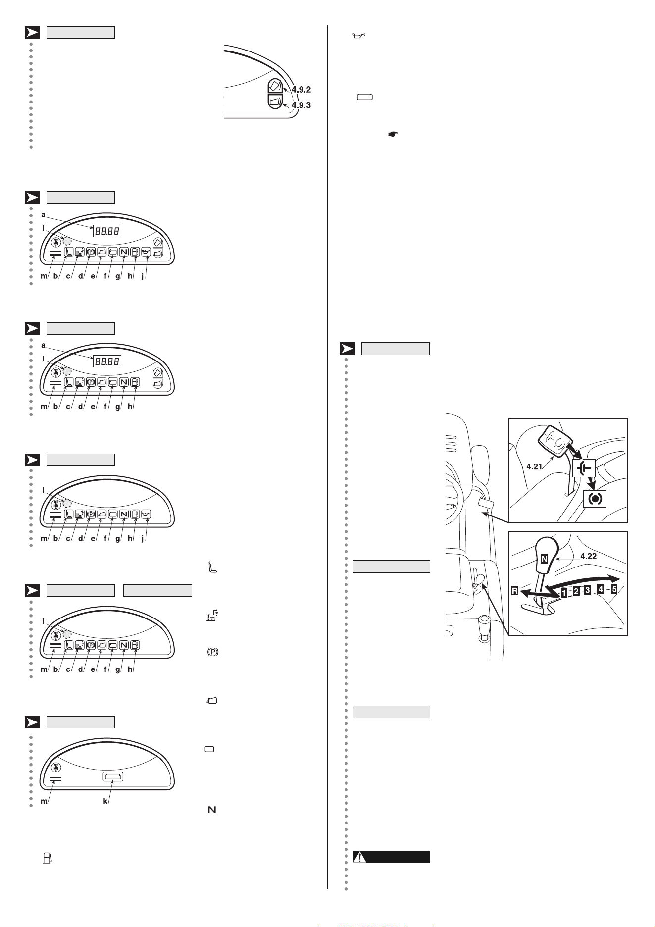
4.10 INDICATOR LIGHTS AND SOUND WARNINGS ON THE
DASHBOARD
a) The display comes on
when the key is inserted
(4.4):
– it indicates the battery volt-
age in the «ON» position,
before starting the engine;
– it indicates the engineʼs to-
tal operation time in the
«ON» position, with the
engine started;
– a blinking decimal point (.)
indicates that the counter
is working.
The warning lights come on
when the key is in the «ON»
position and stay on simulta-
neously for approximately 2
seconds (in combination with
an intermittent warning so -
und) to indicate proper func-
tioning.
Afterwards, when a warning
light comes on, it indicates:
b) seat without
operator;
c) blades engaged;
d) parking brake
engaged;
e) missing
grass-catcher
or stone-guard;
f) insufficient battery
recharge; look for
the causes in chap-
ter 8 of this manual;
g) transmission in
“neutral” position.
h) low fuel: it means that approx. 1.5 liters are left in the tank,
which is enough for 30-40 minutes of normal work;
HF2•••HT•
j) problems with the engineʼs lubrication: turn the engine off im-
mediately and check the oil level (5.3.3). If the problem per-
sists, contact your Dealer.
k) This warning light comes on when the key (4.4) is in the
«ON» position and always stays on while operating.
If it blinks, it means that the engine cannot be started
( 5.2).
l) The sensor located inside the dashboard turns on the headlights
automatically (in models where included) after approximately few
of darkness and turns them off after few seconds of light.
– To avoid unnecessary use of them, keep the area near the sen-
sor clean and do not place rags or objects on the dashboard.
m) There are two types of sound warnings:
– continuous the electronic cardʼs protection device
has cut in;
– intermittent warning that the grass-catcher is full.
4.21 CLUTCH / BRAKE PEDAL
This pedal has a
dual function: dur-
ing the first part of
its stroke, it acts as
a clutch, engaging
and disengaging
dri ve to the wheels,
and in the second
part it acts as a
bra ke on the rear
wheels.
Do not keep the
pedal halfway be-
tween clutch en-
gagement and di -
sengagement for
a long time; this
can cause
o ver heating and
con sequent damage to the transmission belt.
When the machine is in movement, keep your
foot off the pedal.
4.22 SPEED CHANGE LEVER
This lever has seven positions for the five forward speeds, the
neutral position «N», and reverse «R». To go from one speed to
another, press the pedal (4.21) halfway and move the lever as per
the instructions on the label.
Reverse must be engaged only when the
machine is stopped.
WARNING!
NOTE
IMPORTANT
HF2•••SB•
8EN
HF2620HT•
HF2620HM•
HF2417HM•HF2315HM•
HF2315SB•
HF2417HT•
5. HOW TO USE
5.1 SAFETY RECOMMENDATIONS
The machine must only be used for the pur-
pose for which it was designed (cutting and collection of
grass).
Using the machine in any other way is considered "impro per
use" which will invalidate the warranty, relieve the manufac-
turer from all liabilities, and the user will consequently be
liable for all and any damage or injury to himself or others.
Examples of improper use may include, but are not limited to:
– transport people, children or animals on the machine or on
a trailer;
– tow or push loads without the use of the specified acces-
sory for towing;
– use of the machine for moving over unstable, slippery,
icy, stony, rough, marshy ground and puddles that do not
allow for evaluation of the consistency of the ground;
– use of the machine for leaf or debris collection;
– use of the blades on surfaces other than grass.
Do not tamper with or remove the safety d e-
vices fitted to the machine. REMEMBER THAT THE USER IS
ALWAYS RESPONSIBLE FOR DAMAGE AND INJURIES TO
OTHERS.
Before using the machine:
– read the general safety regulations ( 1.1), paying parti -
cular attention to driving and cutting on slopes;
– carefully read the instructions for use, become familiar
with the controls and on how to quickly stop the blades and
engine.
– never put your hands or feet next to or beneath the rotat-
ing parts and always keep away from the discharge open-
ing.
Do not use the machine when in a precarious state of health
or under the effect of medicines or other substances that can
reduce your reflex actions and your ability to concentrate.
It is the user's responsibility to assess the potential risk of the
area where work is to be carried out, as well as to take all the
necessary steps to ensure his own safety and that of o thers,
particularly on slopes or rough, slippery and unstable ground.
Do not leave the machine stopped in high grass with the en-
gine running in order to avoid the risk of starting a fire.
This machine must not be used on slopes
greater than 10° (17%) ( 5.5).
All the references relating to the positions of
controls are those described in chapter 4.
5.2 WHY THE SAFETY DEVICES CUT IN
The safety devices work in two ways:
– they prevent the engine from starting if all the safety requirements
have not been met;
– they stop the engine if even just one of the safety requirements
is lacking.
To start the engine, in all cases it is necessary that:
– the transmission is in “neutral”;
– the blades are not engaged;
– the operator is seated or the parking brake is engaged.
DANGER!
IMPORTANT
WARNING!
DANGER!
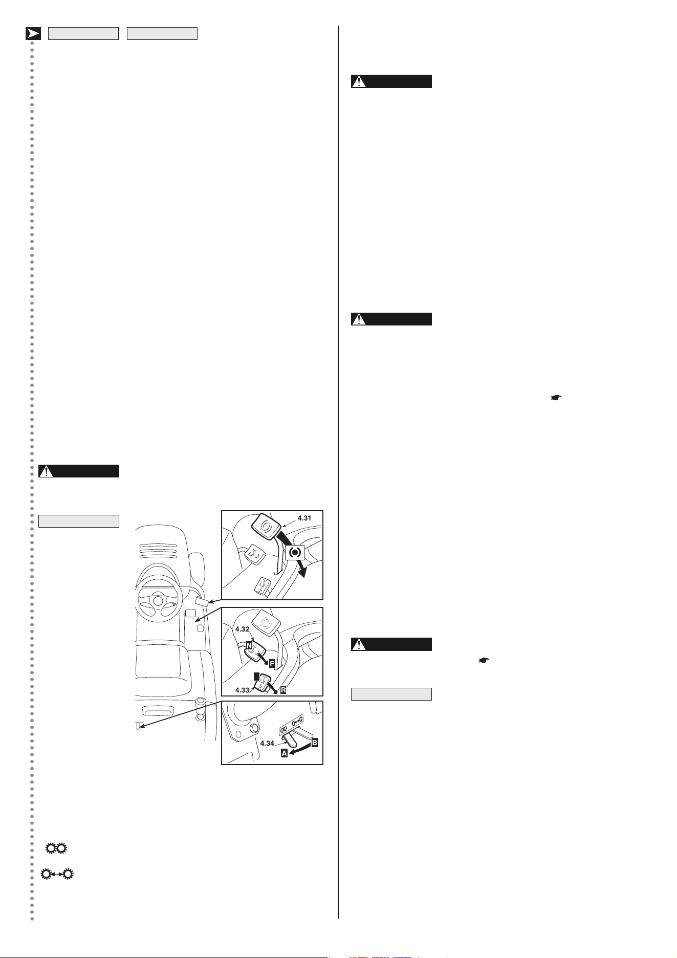
4.31 BRAKE PEDAL
This pedal works the brake on the rear wheels.
4.32 FORWARD GEAR PEDAL
This pedal engages drive in the rear wheels and modulates the
machine's speed.
– Increasing pressure on the pedal progressively increases the
speed of the machine.
– The pedal automatically goes into neutral «N» when released.
– The neutral condition «N» is shown by the lighting of an indi-
cator light (4.10.g).
4.33 REVERSE PEDAL
This pedal engages reverse drive in the wheels and modulates
the machineʼs speed.
– Increasing pressure on the pedal progressively increases the
speed of the machine.
– The pedal automatically goes into neutral «N» when released.
– The neutral condition «N» is shown by the lighting of an indi-
cator light (4.10.g).
Reverse must be engaged only when the
machine is stopped.
If one of the drive
pedals is used
when the parking
brake (4.5) is en-
gaged, the engi -
ne stops.
4.34 LEVER TO RELEASE THE HYDROSTATIC
TRANSMISSION
This lever has two positions as shown on the label:
«A» = Transmission engaged: for all usage conditions,
when moving and during cutting;
«B» = Transmission released: considerably reduces
the effort required for moving the machine by
hand, with the engine turned off.
HF2•••HM• HF2•••HT•
NOTE
WARNING!
9EN
N
The engine stops when:
– the operator leaves his seat when the blades are engaged;
– the operator leaves his seat when the transmission is not in
“neutral”;
– the operator leaves his seat with the transmission in “neutral” but
without engaging the parking brake;
– the grass-catcher is lifted or the stone-guard is removed when the
blades are engaged;
– the reverse gear is engaged with the blades engaged. This can
be avoided by keeping the push-button 4.7 pressed.
The table below shows various operating conditions, highlighting
why the safety device shuts down the engine.
5.3 PRELIMINARY OPERATIONS BEFORE STARTING WORK
Before starting to work it is necessary to carry out several checks and
operations to ensure that the work gives the best results and is done
in maximum safety.
5.3.1 Seat adjustment
To adjust the seat position, the
four fixing screws (1) must be
loosened. Move the seat along
the support slots.
When you find the desired po-
sition, tighten the four screws
(1).
The sliding seat can be ad-
justed onto six different posi-
tions.
The position is changed by
pulling up the handle (1) and
sliding the seat until it is locked
into the desired position.
HF2•••◊M• HF2•••◊T•
HF2•••◊B•
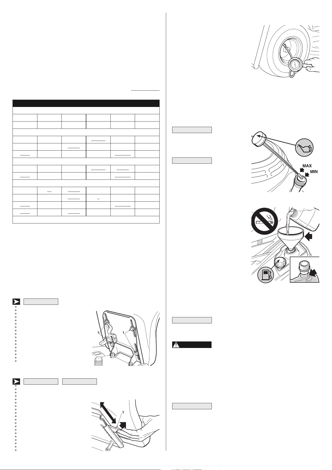
5.3.2 Tyre pressure
Unscrew the hubcaps and connect
the valve caps to a compres sed air
line with a gauge.
Proper tyre pressure levels arevi-
tal for perfect alignment of the cut-
ting deck and thus mows evenly.
The pressures are:
FRONT 1.5 bar (13 x 5.00-6)
1.0 bar (15 x 5.00-6)
REAR 1.2 bar
5.3.3 Filling with oil and fuel
Use oil SAE
10W30 and Petrol Unleaded
Euro 95.
Running the
en gine with an insufficient a -
mount of oil can damage it very
seriously. The use of a non-de-
tergent or two-stroke engine oil
can reduce the life of the en-
gine.
On a flat surface and with the en-
gine off, remove the cap with the
dipstick and dry it. Push it fully in
without screwing it on, then take it
out and check the oil level. If the
level is close to or below the lower
limit (MIN) of the dipstick, top up
with the recommended oil until the
upper limit (MAX) is reached.
Screw the dipstick cap back on.
Refuel using a funnel. Avoid overfilling; filler neck has a max level
indication.
The tank's capacity is 5.4 litres.
In the event of spilling on the body, quickly re-
move perol traces.
Refuelling should be carried out in an open or
well ventilated area with engine stopped. Always remember
that petrol fumes are inflammable. DO NOT TAKE A NAKED
FLAME TO THE TANKʼS OPENING IN ORDER TO SEE THE
TANKʼS CONTENTS AND DO NOT SMOKE WHEN REFU-
ELLING.
• Fuel containing alcohol
If you intend to use fuel with alcohol, ensure that
its octane number is at least as high as that recommended by
Honda (86). There are two types of fuel/alcohol mixtures: one con-
tains ethanol and the other methanol.
Do not use mixtures containing more than 10% ethanol, or fuel
containing methanol (methyl or wood alcohol), which do not con-
tain cosolvents, or corrosion inhibitors for methanol.
IMPORTANT
NOTE
DANGER!
IMPORTANT
IMPORTANT
10EN
OPERATOR GR.-CATCHER BLADES TRANSMISSION BRAKE ENGINE
A) PILOT LAMPS ON (Key in «ON» position)
Sitting YES Disengaged «N» Engaged Stopped
Sitting NO Disengaged «N» Disengaged Stopped
B) WHEN STARTING (Key in «START» position)
Sitting –/– Disengaged 1...5 - F / R Engaged Does NOT start
Sitting –/– Engaged «N» Engaged Does NOT start
Absent –/– Disengaged «N» Disengaged Does NOT start
C) WHEN MOVING (Key in «ON» position)
Sitting YES Disengaged 1...5 - F / R Engaged Stops
Absent YES Disengaged «N» Disengaged Stops
D) WHEN CUTTING GRASS (Key in «ON» position)
Sitting NO Engaged –/– Disengaged Stops
Sitting YES Engaged R Disengaged Stops *
Absent YES Disengaged «N» Disengaged Stops
Absent YES Engaged –/– Engaged Stops
* This may be avoided by keeping the push-button 4.7 pressed
11 EN
In the case of a mixture containing methanol with addition of co-
solvents and corrosion inhibitors, limit the proportion to 5% of
methanol.
The guarantee does not cover damage caused to the fuel system
or engine performance problems resulting from the use of fuel con-
taining alcohol. Honda does not give its approval to the use of fu-
els containing methyl alcohol since their suitability is not yet
proven.
5.3.4 Checking the braking system
Make sure that the machineʼs braking capacity is adequate for the
conditions of usage. Avoid starting the machine if you have doubts
on the brake efficiency.
If necessary, adjust the brake ( 6.3.4). If you still have doubts
about its efficiency, contact your Dealer.
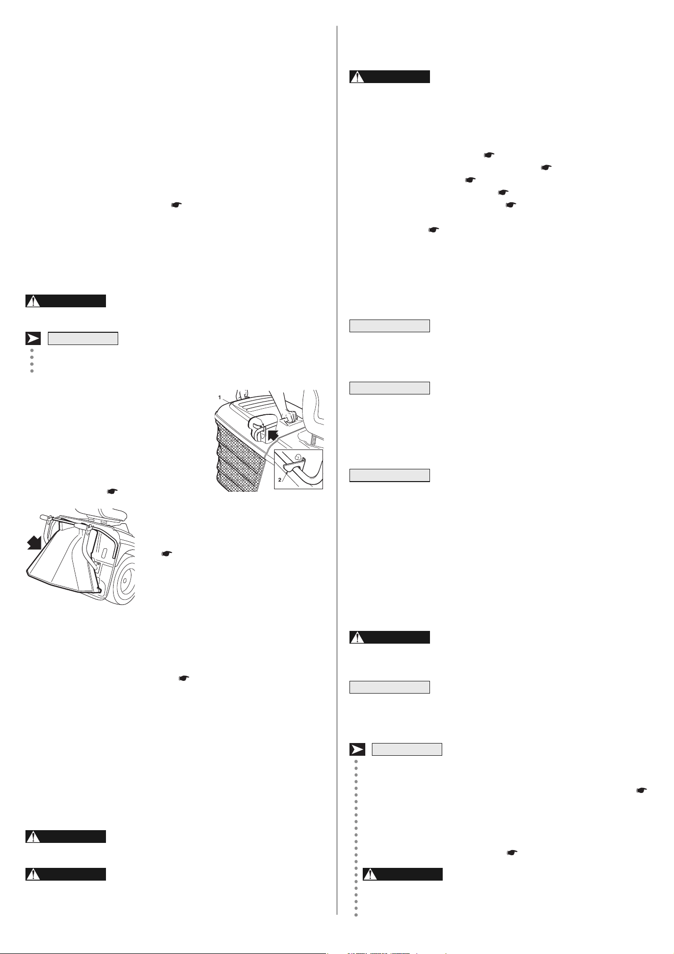
5.3.5 Fitting the protection devices at the exit
(grass-catcher or stone-guard)
Never use the machine without having fitted
the protection devices at the exit!
The protection devices must be fitted with the tipping levers low-
er ed.
Attach the grass-catcher inserting the up-
per tube of the frame into the slots of the
2 brackets (1).
Make sure that the lower tube of the
opening of the grass-catcher hooks onto
the pawl (2).
If the hook is too stiff or too loose, adjust
the return spring (
6.3.6).
If you would like to mow without using the
grass-catcher, an optional stone-guard
kit ( 9.2) is available on request. This
has to be attached to the rear plate as in-
dicated in the relevant instructions.
5.3.6 Checking the effectiveness of the safety devices
Check that the safety systems are working properly by simulating the
various situations of usage listed ( 5.2) and making sure that the
indicated result is achieved for each situation.
5.3.7 Checking the blades
Check that the blades are sharpened properly and firmly fixed to their
hubs.
– A badly sharpened blade pulls at the grass and causes the lawn
to turn yellow.
– A loose blade causes unusual vibrations and can be dangerous.
Wear heavy gloves when handling the
blades.
Disengage drive to attachments, stop the en-
gine and remove the ignition key before cleaning, checking or
working on the machine.
WARNING!
WARNING!
HF2•••HT•
WARNING!
5.4 USING THE MACHINE
5.4.1 Starting
All starting operations have to be effected in
an open or well-ventilated area! ALWAYS REMEMBER THAT
THE ENGINEʼS EXHAUST FUMES ARE TOXIC!
To start the engine:
– engage the parking brake ( 4.5), on sloping ground;
– put the transmission into neutral («N») ( 4.22 or 4.32/33);
– disengage the blades ( 4.8);
– if started cold, use the choke ( 4.2);
– position the accelerator lever ( 4.3) between «SLOW» and
«FAST»;
– put in the key ( 4.4), and turn to «ON» to make electrical con-
tact, then turn to «START» to start the engine;
– release the key once the engine has started.
When the engine has started, put the accelerator in the «SLOW» po-
sition and close the choke (if fitted).
The choke must be closed as soon as the engine
is running smoothly. Using it when the engine is already warm can
foul the spark plug and cause the engine to run erratically.
Should you have difficulties in starting do not per-
sist with using the starter motor as this can run down the battery
or flood the engine. Turn the key to the «OFF» position, wait for
a few seconds and then repeat the operation. Should the mal-
function persist, refer to chapter «7» of this manual.
Always bear in mind that the safety devices pre-
vent the engine starting when:
– the blades are engaged;
– the transmission is not in neutral («N»).
– the operator is absent with the parking brake disengaged.
In these cases, once the situation has been corrected, the key
must first be turned back to «OFF» before the engine can be
restarted.
5.4.2 Forward drive and moving without mowing
This machine has not been approved for use
on public roads. It has to be used (as indicated by the High-
way Code) in private areas closed to traffic.
When moving the machine, the blades must be
disengaged and the cutting deck put at its highest position (posi-
tion «7»).
Put the accelerator control between the «SLOW» and «FAST»
positions, and the gear change lever in the 1st speed position (
4.22).
Keep the pedal pressed down and disengage the parking brake.
Slowly release the pedal which will turn from «brake» to «clutch»,
thus operating the rear wheels ( 4.21).
The pedal has to be released gradually as
a sudden engagement may cause tipping up and loss of
control of the vehicle.
WARNING!
DANGER!
HF2•••SB•
NOTE
WARNING!
IMPORTANT
NOTE
IMPORTANT
12EN
To change the position, unscrew end
remove the pin (1) then reposition
the wheel (2) in the upper or lower
hole of the wale shown on the dia-
gram.
This work is to
be done to all four wheels,
WITH THE ENGINE OFF AND
THE BLADES DISENGAGED.
To start cutting:
– put the accelerator into the «FAST» position;
– bring the cutting deck to the highest position;
– engage the blades ( 4.9);
– start moving forwards onto the grass area very gradually and with
particular caution, as previously described;
– adjust the forward speed and the cutting height ( 4.6) accord-
ing to the lawn condition (height, density and dampness of the
grass). On flat ground, these general conditions can be followed:
High and dense grass - wet lawn 2,5 km/h
Average condition grass 4 ... 6 km/h
Low grass - dry lawn over 6 km/h
The speed is controlled in a gradual and progressive way by the
pressure on the drive pedal.
When cutting on sloping ground, the forward
speed must be reduced to ensure safe conditions ( 1.2 -
5.5).
In any case, the speed should always be lowered if you note a re-
duction in engine speed, since a forward speed that is too fast
compared to the amount of grass being cut will never mow the grass
well.
Disengage the blades and put the cutting deck in the highest posi-
tion whenever you need to get past an obstacle.
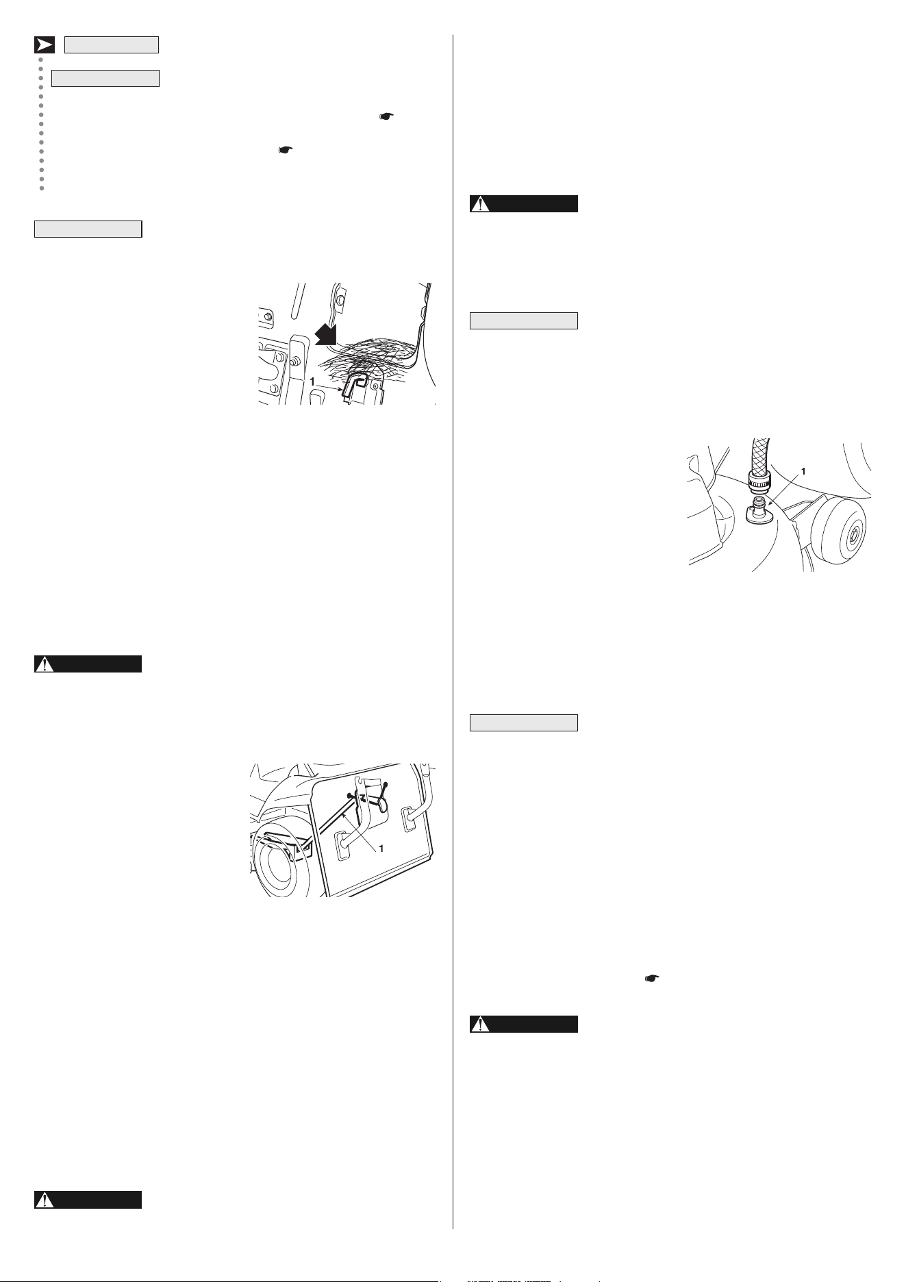
5.4.6 Emptying the grass-catcher
Do not let the grass-catcher become too full as this may block the
collector channel. When the grass-catcher is full there is an inter-
mittent audible warning.
At this point:
– lower the engine speed;
– go into neutral (N) ( 4.22 or
4.32/33) and stop forward movement;
– engage the parking brake on slopes;
– disengage the blades ( 4.8) and
the audible signal will stop;
Emptying the
grass-catcher can only be done
with the blades disengaged, other-
wise the engine stops.
– pull out the lever (1) ( 4.9.1) and
tip up the grass-catcher to empty
it;
– close up the grass-catcher so that
it hooks onto the pawl stop (2) and
put the lever (1) back into place.
WARNING!
NOTE
HF2•••SB• HF2•••HM•
WARNING!
HF2•••HM• HF2•••HT•
Gradually reach the desired operating speed using the acceler-
ator and gear lever. To change the gear speed the clutch must be
used pushing the pedal down half way ( 4.21).
Put the accelerator lever in a midway position between «SLOW»
and «FAST».
Disengage the parking brake and release the brake pedal
( 4.31).
Press the drive pedal forward ( 4.32) and go to the required
speed by gradually increasing pressure on the pedal and press-
ing the accelerator appropriately.
Drive must be engaged in the way already
described ( 4.32) to prevent sudden engagement from
causing tipping up and loss of control of the vehicle, par-
ticularly on slopes.
5.4.3 Braking
First, reduce the machineʼs speed by reducing the engineʼs r.p.m.
and then push the brake pedal ( 4.21 or 4.31) to further reduce
the speed until the machine stops.
The machine already slows down consider-
ably by just releasing the drive pedal in forward or reverse.
5.4.4 Reverse
Reverse must be engaged ONLY when the machine is stopped.
Push down the pedal until the machine stops and then insert re-
verse by moving the lever sideways and putting it into position
«R» ( 4.22). Gradually release the pedal to engage the clutch
and then begin moving in reverse.
When the machine is stopped, start the reverse movement by
pressing the drive pedal in the «R» direction ( 4.33).
5.4.5 Grass-cutting
When you have reached the area to be mowed, make sure that the
grass-catcher or stone-guard is positioned correctly.
The cutting deck wheels (1) are included so that a space is always
kept between the ground and the edge of the cutting deck to pre-
vent the lawn damage if the ground is uneven.
Each cutting deck wheel can be fitted at two different heights: it
serves to maintain space in the lowest position, whereas it does
not function when in the highest position.
HF2•••HM• HF2•••HT•
WARNING!
HF2•••HM• HF2•••HT•
HF24••◊•• HF26••◊••
HF2•••HM• HF2•••HT•
HF2•••SB•
NOTE
13 EN
The dumping switch operates only with the
bla des disengaged.
– with the operator seated, keep the button (3) ( 4.9.2)
pressed until the grass-catcher is completely tipped over;
– once emptied, keep the button (4) ( 4.9.3) pressed until the
grass-catcher has completely gone down while checking that
the pawl (2) stays hooked on.
At times the audible warning may be heard at the
moment of engaging the blade even when the grass-catcher has
been emptied.This is due to
grass-cuttings left on the sensor
of the micro-switch (1). To stop
the signal, disengage the blades
and then immediately engage
them again. If the warning sound
continues, stop the engine, take
off the grass-catcher and remove
any accumulated grass-cuttings
from the sensor (1).
5.4.7 Unblocking the collector channel
Cutting very tall or wet grass, particularly at too high speed, can
cause the collector channel to become blocked. Should this happen,
it will be necessary to:
– stop forward movement immediately, disengage the blades, stop
the engine and remove the key;
– take off the grass-catcher or stone-guard;
– remove the accumulated cuttings, reaching them from the outlet
of the collector channel.
This job must only be performed with the en-
gine turned off.
5.4.8 “Mulching” function (optional)
The “Mulching” cap recycles grass
inside the cutting deck, chopping it
into fine strands and strewing them
evenly on the lawn.
This accessory must be mounted
as shown in the relative instruc-
tions.
5.4.9 End of mowing
When you have finished mowing, disengage the blades, lower the
engine speed and return with the cutting deck in the highest posi-
tion.
5.4.10 End of work
Stop the machine, put the accelerator lever in the «SLOW» position
and turn off the engine by putting the key into the «OFF» position.
This operation makes the fuel valve automatically close.
Always take out the ignition key if leaving the
machine unattended!
HF2•••HT•
WARNING!
NOTE
NOTE
WARNING!
5.4.11 Cleaning and storage
Put the machine away in a dry place protected from weather and, if
possible, cover with a cloth. After each mowing, clean the outside of
the machine, empty the grass-catcher and shake it to remove resid-
ual grass and earth.
Look for and eliminate all the grass that has accumulated inside the
engine compartment and above the cutting deck, to keep the ma-
chine at an optimal level of efficiency.
Always empty the grass-catcher and do not
leave containers full of cut grass inside a room.
Clean the plastic parts of the body with a damp sponge using wa-
ter and detergent, taking care not to pu water on the engine, the elec-
trical parts or the electronic card located under the dashboard.
Never use hose-nozzles or harsh detergents for
cleaning the body and engine!
For washing the inside of the cutting deck and the collector channel
the machine must be on firm ground with:
– the grass-catcher
or stone-guard fitted;
– the operator seated;
– the engine running;
– the transmission in neutral;
– the parking brake engaged;
– the blades engaged.
Connect a water hose to the pipe fittings (1) alternating, and run wa-
ter through for a few minutes each, with the blades turning.
When washing, the cutting deck should be fully lowered.
Then take off the grass-catcher, empty and rinse it, and then put it
in a position where it can dry quickly.
To avoid impairing the efficient working of the
electromagnetic clutch:
– prevent the friction from coming into contact with oil;
– do not direct jets of high-pressure water directly onto the clutch
unit;
– do not clean the clutch with petrol.
5.4.12 Storage and inactivity for long periods
If the machine is likely to be unused for a long period (more than 1
month), disconnect the ground (black) cable from the battery. Lu-
bricate all joints as directed ( 6.2.1).
Carefully remove any dry grass cuttings
which may have collected around the engine or silencer to
prevent their catching fire the next time the machine is used!
Empty the fuel tank by disconnecting the tube situated at the inlet
of the fuel filter (1).
Reconnect the fuel tube.
Loosen the carburetor drain screw (2), and drain the fuel into an ap-
proved gasoline container. Tighten the carburetor drain screw.
WARNING!
WARNING!
IMPORTANT
IMPORTANT
14EN
highest wheels do not hit obstacles (such as stones, branches,
roots, etc.) that may cause the machine to slide sideways, tip over
or otherwise cause loss of control.
REDUCE SPEED BEFORE ANY CHANGE OF
DIRECTION ON SLOPES, and always engage the parking
brake before leaving the machine stopped and unattended.
Take care when beginning forward move-
ment on sloping ground to prevent the risk of tipping up.
Reduce the forward speed before going on a slope, particu-
larly downhill.
Never use reverse to reduce speed going
downhill. control of the machine may be lost, particularly on
slippery surfaces.
Never ride the machine on slopes in neu-
tral gear or with the clutch out! Always engage a low gear
before leaving the machine stopped and unattended.
Go down slopes without touching the pedal ( 4.32/33) to take
advantage of the braking effect of the hydrostatic drive when the
transmission is not engaged.
5.6 TRANSPORTING
If the machine must be transported on a lorry
or trailer car, use access ramps having proper strength,
width and length. Load the machine with the engine turned
off, without driver and only pushed by a proper number of
people. Lower the cutting deck, engage the parking brake and
properly secure the machine to the means of transportation
with cables or chains during transportation.
5.7 ADVICE ON HOW TO OBTAIN A GOOD CUT
1. To keep a lawn green and soft with a good appearance, it
should be cut regularly and without damaging the grass.
2. It is always better to cut the grass when dry.
3. The blades must be in good condition and well sharpened so
that the grass is cut straight without any ragged edge that leads
to yellowing at the ends.
4. The engine must run at full speed, both to ensure a sharp cut
of the grass and to get the necessary thrust to push the cuttings
through the collector channel.
5. The frequency of mowing should be in relation to the rate of
growth of the grass, which should not be left to grow too much
between one cut and the next.
6. During hot and dry periods, the grass should be cut a little higher
to prevent the gro und
from drying out.
7. If the grass is very tall,
it should be cut twice in
a twenty-four hour pe-
riod. The first time with
the blades at maximum
height, possibly reduc-
ing the cutting width,
and the second cut at
the desired height.
DANGER!
DANGER!
WARNING!
HF2•••SB•
DANGER!
WARNING!
HF2•••HM• HF2•••HT•
Remove the two spark plugs and pour about a tablespoon of clean
engine oil into the cylinders. In order to distribuite the oil in the cylin-
ders evenly, crank the engine during 1 or 2 seconds using the
starter motor, turning the starter key; then reinstall the spark plugs
( 6.4.5).
Petrol is highly flammable. Store the fuel in
special containers. Always put the tank and fuel container
caps back on and tighten well.
The battery must be kept in a cool and dry place.
Before a long storage period (more than 1 month), always charge
the battery, only with the specific charger supplied with your ma-
chine, and then recharge before using again ( 6.2.3).
The next time the machine is used, check that there are no fuel leaks
from the tubes or carburettor.
5.4.13 Card protection device
The electronic card has a self-resetting protector which breaks the
circuit if there is a fault in the electrical system. It results in the stop-
ping of the engine and an audible signal which can only be stopped
by removing the key.
The circuit automatically resets after a few seconds but the cause
of the fault should be ascertained and dealt with to avoid re-activating
the protection device.
To avoid activating the protection device:
– do not reverse the leads on the battery terminals;
– do not use the machine without its battery or damage may be
caused to the charging regulator;
– be careful not to cause short-circuits.
5.5 USING ON SLOPING GROUND
Only mowing in any case on
the maximum gradients al-
ready mentioned (max 10° -
17%), lawns on a slope have
to be mowed moving up and
down and never across them,
taking great care when
changing direction that the
DANGER!
IMPORTANT
IMPORTANT
HF2620◊••HF24••◊••HF23••◊••
HF24••◊••HF23••◊•• HF2620◊••
WRONG!
RIGHT!
15 EN
8. The appearance of the lawn will improve if you alternate the cut-
ting in both directions.
9. If the collector system tends to get blocked with grass, you
should reduce the forward speed since this may be too high for
the condition of the grass. If the problem persists, the probable
causes are either badly sharpened blades or deformed wings.
10. Be very careful when mowing near bushes or low kerbs which
could distort the horizontal position and damage the edge of the
cutting deck as well as the blades.
5.8 SUMMARY OF THE MAIN OPERATIONS TO BE CARRIED
OUT IN VARIOUS CONDITIONS OF USE
6. MAINTENANCE
6.1 SAFETY RECOMMENDATIONS
Before cleaning, maintenance or repair work,
take out the ignition key and read the relevant instructions.
Wear suitable clothing and heavy gloves when dismantling
and refitting the blades and in all other hazardous situations
for hands.
Never use the machine with worn or da ma -
ged parts. Faulty or worn-out parts must always be replaced
and not repaired. Only use genuine spare parts: those that
are not of an equivalent quality may damage the machine or
endanger the safety of yourself and others.
Never get rid of used oil, fuel or other pollutants
in unauthorised places!
Summary of the main situations where work may be required
IMPORTANT
WARNING!
WARNING!
To ... You will need to ...
Start the engine ( 5.4.1)
Ensure that all the conditions
allowing starting are met, and
then turn the key.
Go forward ( 5.4.2)
Move the accelerator;
:
push the pedal
right down, engage the gear
( 4.22) and then gradually
release the pedal;
:
press
the drive pedal forward
( 4.32);
HF2•••HM• HF2•••HT•
HF2•••SB•
Brake or stop ( 5.4.3)
Reduce the engine speed and
press the brake pedal.
Reverse ( 5.4.4)
Stop the machine;
:
put into neutral
(N), push the pedal right down,
engage reverse, ( 4.22) and
then gradually release the pedal;
:
press
the drive pedal in reverse;
( 4.33).
HF2•••HM• HF2•••HT•
HF2•••SB•
Cut the grass ( 5.4.5)
Fit the grass-catcher or stone-
guard, adjust the height of the
cutting deck wheels and move the
accelerator; engage the blades
and adjust the cutting height.
: push the pedal
right down, engage the gear
( 4.22) and then gradually
release the pedal;
: press
the drive pedal forward
( 4.32);
HF2•••HM• HF2•••HT•
HF2•••SB•
Empty the grass-catcher
( 5.4.6)
Stop forward movement,
disengage the blades, and
activate the control for tipping up
the grass-catcher.
Unblock the collector channel
( 5.4.7)
Stop forward movement, disengage
the blades and turn off the engine;
remove the grass-catcher and clean
the channel.
End mowing ( 5.4.8)
Disengage the blades and reduce
the engine speed.
Stop the engine ( 5.4.9)
Reduce the engine speed, wait a
few seconds, and turn the key.
Store the machine ( 5.4.10)
Engage the parking brake, re-
move the key and, if necessary,
wash the machine, the inside of
the cutting deck, the collector
channel and the grass-catcher.
Every time that ... You will need to ...
The blades vibrate
Check the bolts (
6
.3.1) or balance
the blades (
6
.3.1).
The blades tear the grass and the
lawn becomes yellow
Sharpen the blades ( 6.3.1).
The cut is uneven Adjust the alignment of the cutting
deck ( 6.3.2)
The blades engage in an
abnormal way
Regulate the blade engagement
adjuster ( 6.3.3)
The machine does not brake
Adjust the brake spring ( 6.3.4)
Forward movement is erratic Adjust the stretcher spring
( 6.3.5).
The grass-catcher jumps around
and tends to open up
Adjust the spring ( 6.3.6)
6.2 ROUTINE MAINTENANCE
6.2.1 Guide to scheduled maintenance
This table is to help you maintain your machineʼs safety and per-
formance. It shows the main maintenance and lubrication work,
indicating the frequency with which it should be carried out.
To the right of each item there is a box where you or your Dealer
write the date or after how many hours of operation the work was
carried out.
WORK HOURS DONE (DATE OR N° OF HOURS)
1. MACHINE
1.1 Check of tightness and sharpness of blades 25
1.2 Blade replacement 100
1.3 Check the transmission belt
2)
25
1.4 Transmission belt replacement
2)
–
1.5 Check the blade drive belt
2)
25
1.6 Blade drive belt replacement
2)
–
1.7 Check the belt connecting blades
2)
25
1.8 Replacement of belt connecting blades
2)
–
1.9 Check and adjustment of brake 10
1.10 Check and adjustment of drive 10
1.11 Check engagement and brake of blade 10
1.12 Check all fastenings for tight fitting 25
1.13 General lubrication
2) 3)
25
1.14 Check the battery level 25
1.15 Battery charge 100
2. ENGINE
2.1 Check oil level
1)
–
2.2 Engine oil change
4)
100
2.3 Oil filter replacement
4)
100
2.4 Check
1)
and cleaning of air filter
5) 6)
50
2.5 Air filter replacement
6)
300
2.6 Check fuel filter
2)
100
2.7 Fuel filter replacement
2)
300
2.8 Check and cleaning of spark plug points 100
2.9 Replacement of spark plug 300
1)
Check each time used.
2)
Contact your Dealer.
3)
General lubrication should also be
carried out whenever the machine
is to be left unused for a long peri-
od.
4)
Operation to be performed also af-
ter the first 20 hours of operation.
5)
Carry out maintenance of the air fil-
ter more frequently in the case of
use on dusty ground.
6)
Replace the paper element only.
16EN
Periodically check the electrolyte level, which must be between the
MIN and MAX marks on the battery. When topping off, use ONLY dis-
tilled water for batteries.
6.3 CHECKS AND ADJUSTMENTS
6.3.1 Dismantling, sharpening and balancing blades
Blades that are badly sharpened tear at the grass, reduce collection
and make the lawn turn yellow.
When accessing the blades, remove the cutting
deck that is equipped with a quick release system that makes their
removal from the machine easy.
a) Removing the cutting deck
After moving the cutting height
lever to position «1», loosen the
engagement cable adjuster (1),
pull it out and release the spring
(2).
Free the blades belt (6) from
the clutch pulley (7).
Release the two cotter pins (8)
which hold the two rods (9) onto
the frame.
HF2315◊••
IMPORTANT
6.2.2 Rear axle
This is a sealed single unit which does not require maintenance. It
is permanently lubricated and this lubricant does not need changing
or topping up.
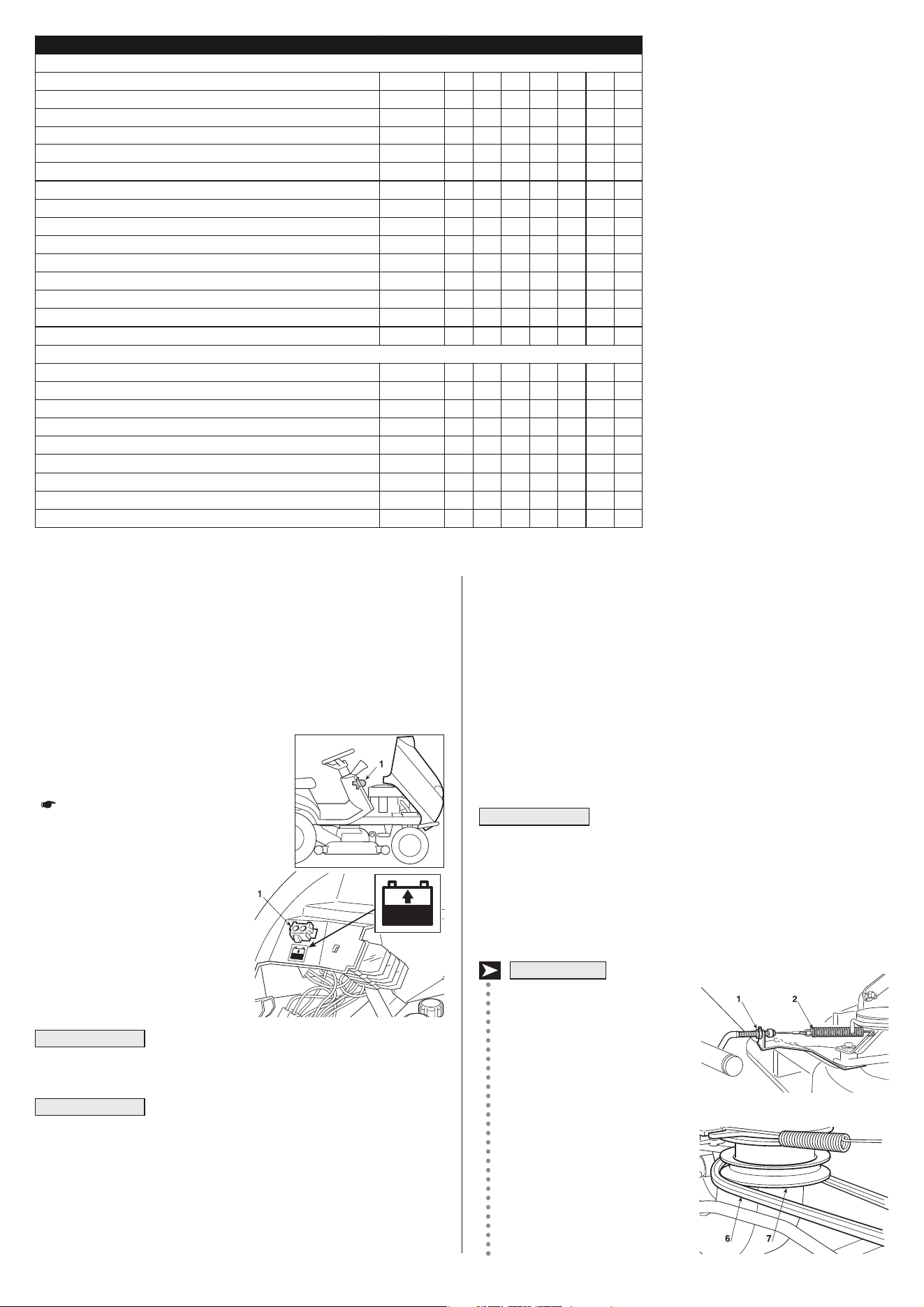
6.2.3 Battery
To ensure long life to the battery, it is es-
sential to keep it carefully maintained.
The battery on your machine must be
charged before using for the first time
( 3.4).
During periods when it is not used,
the charge level can be kept con-
stant by using the maintenance
battery charger supplied. For this
purpose the machine is supplied
with a connector (1) to be con-
nected to the corresponding bat-
tery charger connector.
No device other than the battery charger is to be
connected to this connector.
The charge must be maintained with the battery
charger, following the instructions given in the instruction booklet.
Other recharging systems may definitively damage the battery.
A low battery must be recharged as soon as possible. Otherwise,
irreparable damage could be done to the batteryʼs elements.
IMPORTANT
IMPORTANT
17 EN
Release the three cotter pins
(10) holding the pins onto the
lifting lever, being careful not to
touch the nuts or locknuts in or-
der to keep them parallel for as-
sembly.
Having checked that there is
nothing in the way, the deck can
be removed, taking it out to-
wards the left so that all the pins
come out of their positions.
When assembling, perform the
operations described above in
reverse while making sure that
the front terminal of the collec-
tor channel properly fits into the
exit of the cutting deck.
Put the cutting height adjust-
ment lever into the notch at po-
sition «1».
Only for :
release the spring (1) of the
blade engagement.
Loosen the engagement cable
register (2) and extract it from
the seat.
Free the blades belt (4) from
the clutch pulley (5).
Remove the two cotter pins (6) from the two front connecting rod
pins (7), without loosening or changing the position of the nuts (8)
and locknuts (9).
Remove the two cotter pins (10)
of the rear pins.
After checking that there are no
obstructions, remove the deck
in such a way that all the pins
come out of their housings.
When assembling, ensure that
the two rear holes of the corner
joints are used for fixing the
pins (7). Perform the operations
described above in reverse
while making sure that the front
terminal of the collector channel
properly fits onto the exit of the
cutting deck.
HF24••◊••
HF24••◊••
HF26••◊••
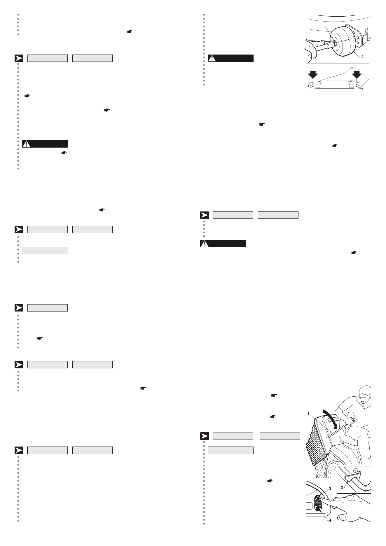
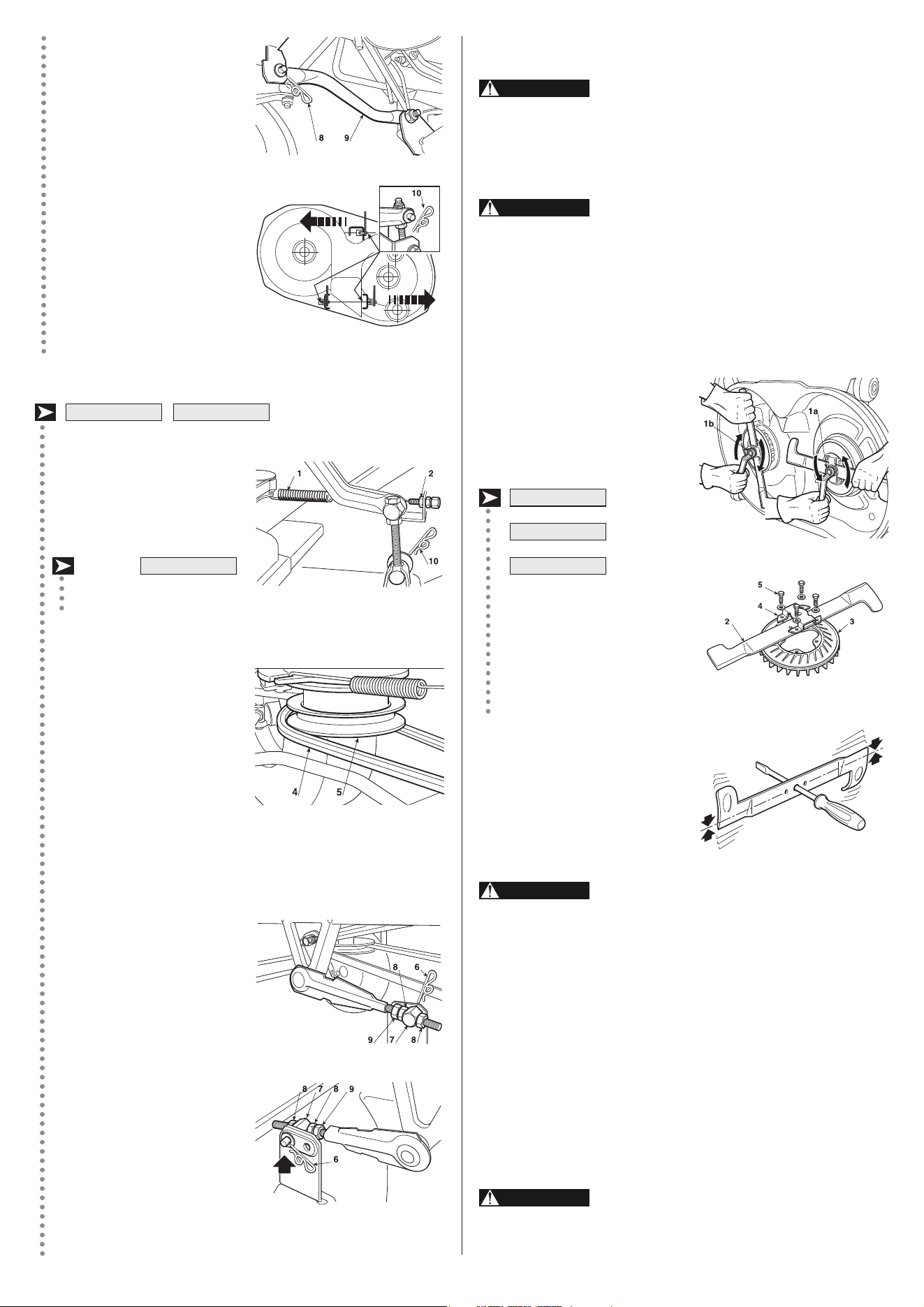
b) Dismantling, sharpening and balancing blades
All operations on the blades (dismantling,
sharpening, balancing, remounting and/or replacing) require
a certain familiarity and special tools. For safety reasons, go
to a specialized centre if you do not have the right tools or ex-
perience.
Wear heavy gloves when handling the bla -
des.
To remove a blade, hold it firmly and undo the central bolt (1a - 1b)
(use 15 mm wrench) in the direction indicated by the arrow for
each blade, noting that one of the fixing bolts has a right-hand
thread and the other one has a left-hand thread.
1a = screw with right thread
(loosen anti-clockwise)
1b = screw with left thread
(loosen clockwise)
The blade (2) is attached to the
fan (3) by a bracket (4) and four
screws with washers (5).
Use a 10 mm key to loosen the
four screws (5) and free the
blade (2) from its bracket (4).
Sharpen the two cutting edges us-
ing a medium grade grinding
wheel and check the balance by
holding the blade up with a screw
driver inserted in the central hole.
Damaged or bent blades must always be re-
placed; never try to repair them! ALWAYS USE MANUFAC-
TURER'S GENUINE BLADES!
Only the following pairs of blades can be used on this machine:
The blades (2) and fans (3) differ and are
contra-rotating. When installing them, make sure that they are
correctly positioned.
WARNING!
WARNING!
HF2620◊••
HF2417◊••
HF2315HM•
WARNING!
WARNING!
HF 2315 SB: 2b 82004354/0 – 82004353/0 2a
HF 2315 HM: 2b 82004345/1 – 82004344/1 2a
HF 2417: 2b 82004341/1 – 82004340/1 2a
HF 2620: 2b 82004343/0 – 82004342/0 2a
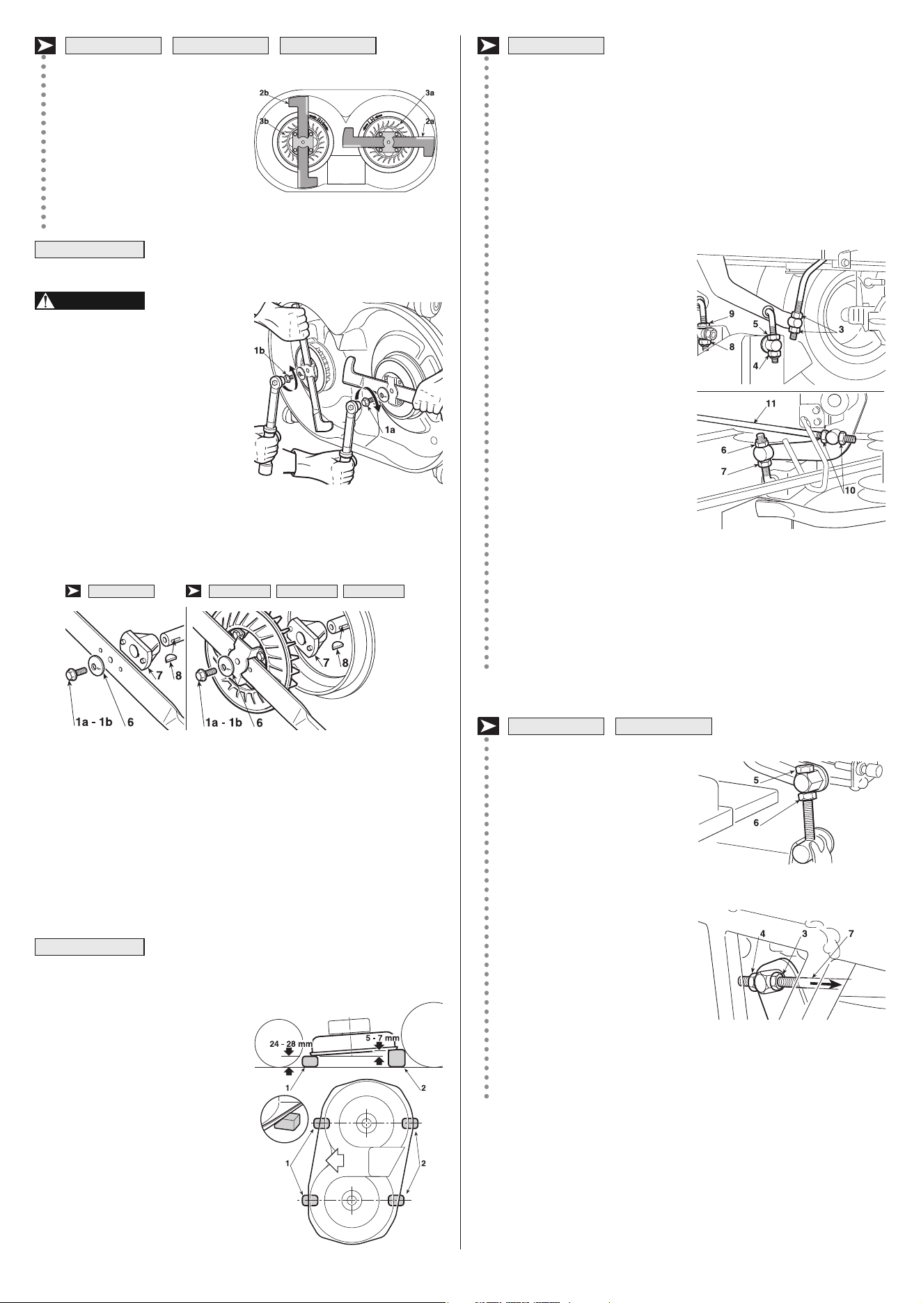
– Completely loosen the two nuts (3), the nuts (4 - 6 - 8) and the
locknuts (5 - 7 - 9) of the three trace rods until the deck is rest-
ing on the blocks;
– turn the two right-hand upper nuts (6 - 8) and the left-hand
lower nut (4) to the point where the deck begins to lift. Tighten
the three locknuts (5 - 7 - 9) and turn the nuts (3) until the slight-
est movement of the lifting lever brings about a similar move-
ment of all the lifting rods.
Any difference in height from
the ground between the left and
right sides of the deck can be
compensated by turning the two
nuts (4 - 8) and locknuts (5 -9)
of just the back rods.
Put the control lever in 2 or 3
different positions and check
that the deck rises evenly and
that at each position it con-
stantly maintains the difference
in height from the ground be-
tween the front and back ed -
ges.
If the front part tends to rise faster or slower it can be adjusted by
turning the nuts (10) on the link rod (11).
Turning the nuts clockwise will lift the front part and make it rise
faster, and turning anti-clockwise will give the opposite effect.
– Loosen the nuts (3), the
screws (5) and the locknuts
(4 – 6) on both the right and
left side, so that the deck is
resting firmly on the blocks;
– push the two connecting rods
(7) to the back and screw
down the two nuts (3) on
each rod until the front part of
the deck just begins to rise
both at the right and the left,
and then tighten the relevant
locknuts (4);
– turn both the rear screws (5) until the rear of the deck begins
to rise both at the right and the left, and then tighten the rela-
tive locknuts (6).
If you are unable to adjust the cutting deck properly, contact your
Dealer.
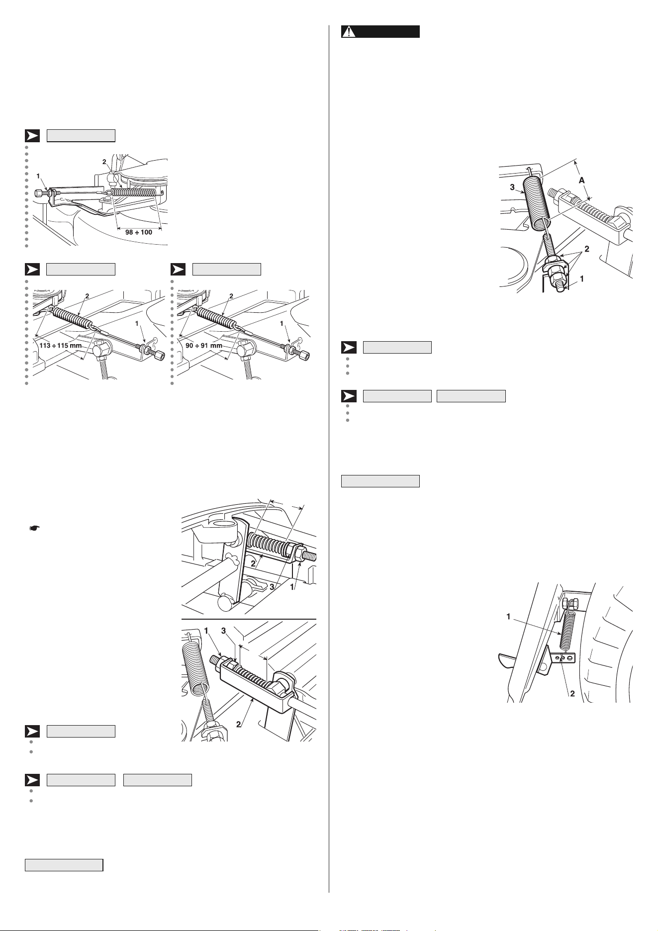
6.3.3 Adjusting blade engagement and blade brake
When the lever to disengage the blades is operated, this also brings
the blade brake into operation for stopping the blades within few sec-
onds.
HF2315◊••
HF24••◊•• HF26••◊••
Reassemble each blade (2a –
2b) onto the respective fan (3a
–3b), following the “RH” (right)
and “LH” (left) indications
printed on the fan and inside
the cutting plate, then tighten
the four screws (5) with the
washers using a dynamometric
key which is calibrated at 9.5 Nm.
The “right” and “left” indications refer to the driv-
ing position.
If one or both
shaft hubs (7) come off when
dismantling the blades, make
sure the keys (8) are securely
lodged in place. When re-fit-
ting the blades, always follow
the indicated sequence, ma k-
ing sure that the blades'
wings are facing towards the
interior of the cutting deck
and that the cupped side of
the cup washer (6) is pressing
against the blade. Tighten the
fixing screws (1a – 1b) using a
torque wrench set to 45-50 Nm.
1a = screw with right thread (tighten clockwise)
1b = screw with left thread (tighten anticlockwise)
6.3.2 Cutting deck alignment
The cutting deck should be properly set to obtain a good cut.
For achieving good results from cutting, the front
part should always be 5 - 7 mm lower than the rear.
– Put the machine onto a flat sur-
face and check the tyre pres-
sures;
– aligned to the center lines of the
two blades, put two blocks (1)
24-28 mm thick under the front
edge of the deck and two blocks
(2) 5-7 mm higher under the
rear edge;
– put the height adjusting lever
into position «1».
HF2315HM• HF2417◊•• HF2620◊••
NOTE
WARNING!
NOTE
18EN
HF2315SB•
HF2620◊••
HF2315HM•
HF2417◊••
If the brake still does not work properly even
after this adjustment, immediately contact your Dealer . DO
NOT ATTEMPT OTHER WORK ON THE BRAKE THAN DE-
SCRIBED HERE.
6.3.5 Adjusting the tension of the drive belt
If you should notice that forward
drive power has dropped, it will be
necessary to adjust the tension of
stretcherʼs spring to return to top
operational conditions.
Access for making this adjustment
is by taking off the inspection hatch
on the tunnel beneath the seat.
Loosen the locking nuts (2) and
tighten or loosen the screw (1) as
much as necessary for a length
«A» of the spring (3) of:
A = 129 - 131 mm
A = 109 - 111 mm
measured to the outside of the end of the spring. When the adjust-
ment has been made, tighten the nuts (2).
When replacing the belt, take great care when
using for the first few times as engagement may be sudden until
the belt is sufficiently run in.
6.3.6 Adjustment of the spring of the pawl for hooking
the grass-catcher
If the grass-catcher tends to jump
about and to open up when going
over rough ground, or if it is difficult
to hook back on after being emp-
tied, the tension of the spring will
need to be adjusted(1).
Change the hooking point by using
one of the holes (2) until the re-
quired result is achieved.
6.4 DISMANTLING AND REPLACEMENT
6.4.1 Oil engine
Drain the oil while the engine is still hot to ensure quick, complete
draining.
Remove the filler cap with the dipstick and place a sheet of card-
board or something similar under the drain tube to prevent the oil
from dripping onto the machineʼs chassis.
WARNING!
HF2•••SB•
NOTE
HF2•••HT•HF2•••HM•
A stretched cable and changes in the length of the belt can impair
the bladesʼ engagement or rotation.
In this case, you have to work on the adjuster according to the dif-
ferent methods provided for each model.
Turn the adjusting nut (1) until the correct spring length (2) is
achieved.
In any event, if the engagement is unable to normally drive the belt
or the blades do not stop within a few seconds after adjustment, im-
mediately contact your Dealer.
6.3.4 Brake adjustment
If the braking distance becomes
longer than the amount indicated
( 5.3.6), the brake spring will
need to be adjusted.
The adjustment will need to be
made while the parking brake is
engaged. Access for making this
adjustment is by taking off the in-
spection hatch on the tunnel be-
neath the seat.
Loosen the nut (1) which holds the
bracket (2) and turn the nut (3) un-
til the length of the spring is:
A = 47,5 - 49,5 mm
B = 45 - 47 mm
measured inside the washers. When the adjustment has been
made, tighten the nut (1).
Do not screw below these levels to avoid over-
loading the brake unit.
IMPORTANT
HF2•••HM• HF2•••HT•
HF2•••SB•
HF2620◊••HF2417◊••
HF2315◊••
19 EN
113 ÷ 115 mm
90 ÷ 91 mm
A
B
A
B
A
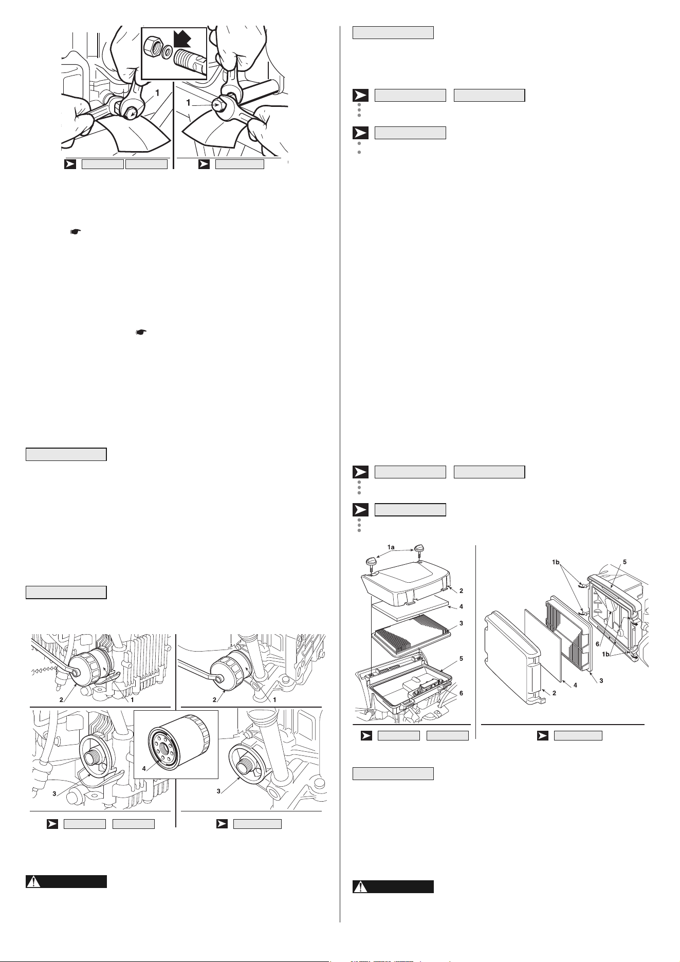
Never run the engine without the air cleaner.
Rapid engine wear will result from contaminants, such as dust and
dirt being drawn into the engine.
1.
:
Release the four latch tabs
(1b) from the air cleaner cover (2), and remove the cover.
:
Remove the two air cleaner cover bolts (1a)
from the air cleaner cover, and remove the cover.
2. Remove the paper element (3) from the air cleaner case. Remove
the foam element (4) from the air cleaner cover.
3. Clean the air filter elements if they are to be reused.
Foam element (4): Clean in warm soapy water, rinse and dry
thoroughly. Or clean in non-flammable solvent and dry.
Paper element (3): Tap the element lightly several times on a
hard surface to remove excess dirt, or blow compressed air (not
exceeding 2.1 kg/cm
2
(30 psi)) through the filter from the air
cleaner case side. Never try to brush the dirt off; brushing will
force dirt into the fibers. Replace the paper element if it is ex-
cessively dirty.
4. Wipe dirt from the inside of the air cleaner case (5) and cover, u -
sing a moist rag. Be careful to prevent dirt from entering the clean
chamber (6) that leads to the carburetor.
5. Reinstall the air cleaner elements and the cover.
:
Tighten the two air cleaner
cover bolts (1a) securely.
:
Hook the latch tabs (1b) securely.
Do not allow dust, dirt, and debris to enter the
clean chamber (air cleaner case) when servicing the air cleaner.
6.4.4 Fuel filter maintenance
Gasoline is extremely flammable and is es-
plosive under certain conditions. Do not smoke or allow
flames or sparks in the area.
WARNING!
NOTE
HF2620◊••
HF23••◊•• HF24••◊••
HF2620◊••
HF23••◊•• HF24••◊••
IMPORTANT
Unscrew plug (1); when refitting the plug take care over the position
of the inner basket.
Fill with the recommended oil until the upper limit of the dipstick is
reached ( 5.3.3). Screw the dipstick cap back on.
6.4.2 Oil filter change
1. Drain the engine oil
( 6.4.1).
2. Remove the oil filter (1) with a filter wrench (2) and let the re-
maining oil drain out. Discard the oil filter.
3. Clean the filter base (3).
4. Coat the new O-ring (4) on the new filter with clean engine oil.
5. Install the new oil filter on the filter base and tighten it by hand un-
til the O-ring seats against the filter base.
6. Tighten the oil filter to the specified torque
(12 Nm - 1.20 kgm).
Use only a Honda genuine oil filter or a filter of
equivalent quality specified for your model. Using the wrong
Honda filter or a non-Honda filter which is not of equivalent qual-
ity may cause engine damage.
7. Pour the specified amount of recommended oil into the engine.
Start the engine and check the filter for leaks.
8. Stop the engine and recheck the oil level. If necessary, add oil to
bring it up to the proper level.
Ask your authorized Honda dealer for advice on
the filter wrench (special tool).
6.4.3 Air cleaner service
Never use gasoline or low flash point sol-
vents for cleaning the air cleaner element. A fire or explosion
could result.
WARNING!
NOTE
IMPORTANT
20EN
HF2620◊••
HF24••◊••HF23••◊••
HF2620◊••HF24••◊••HF23••◊••
HF2620◊••HF24••◊••HF23••◊••
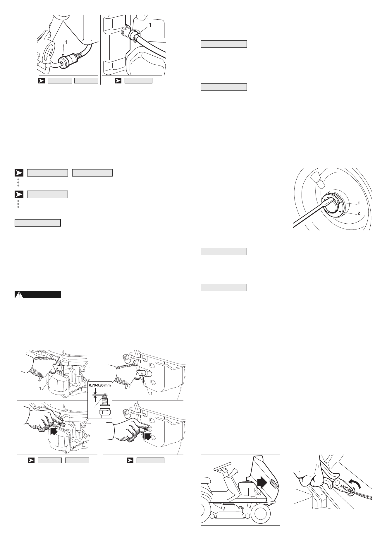
21 EN
Check the fuel filter for water accumulation or sediment.
If the fuel filter contains water accumulation or sediment, take the en-
gine to your authorized Honda engine dealer.
6.4.5 Spark plug service
Recommended spark plugs:
:
BPR5ES (NGK) - W16EPR-U (DENSO).
:
ZGR5A (NGK) - J16CR-U (DENSO)
Never use a spark plugs of incorrect heat range.
To ensure proper engine operation, the spark plugs must be pro -
perly gapped and free of deposits.
1. Remove the spark plug caps and use a spark plug wrench (1) to
remove each spark plug.
If the engine has been running, the muffler
will be very hot. Be careful not to touch the muffler.
2. Visually inspect the spark plugs. Discard the spark plug if there
is apparent wear, or if the insulator is cracked or chipped. Clean
the spark plugs witha wire brush if they are to be reused.
3. Measure the plug gap (2) with a feeler gauge. Correct as ne ces-
sary by bending the side electrode. The gap should be: 0.70 0.80
mm (0.028 0.031 in).
4. Check that the spark plug washer is in good condition and thread
the spark plug in by hand to prevent cross-threading.
WARNING!
IMPORTANT
HF2620◊••
HF23••◊•• HF24••◊••
5. After the spark plug is seated, tighten with a spark plug wrench
(1) to compress the washer.
When installing a new spark plug, tighten 1/2 turn
after the spark plug seats to compress the washer. When rein-
stalling a used spark plug, tighten 1/8 1/4 turn after the spark plug
seats to compress the washer.
The spark plugs must be securely tightened. Im-
properly tightened spark plugs can become very hot and may dam-
age the engine.
6.4.6 Replacing wheels
Stop the machine on a flat surface and put a block under a load-bear-
ing part of the frame on the side that the wheel is to be changed.
The wheels are held by a snap
ring (1) which can be eased off
with a screwdriver.
The rear wheels are directly cou-
pled to the axle shaft and fastened
by a key that forms part of the
wheel's hub.
Should you substitute one or both rear wheels,
ensure that they are of the same diameter, and check that the cut-
ting deck is horizontal to prevent an uneven cut.
Before re-fitting a wheel, smear some grease on
the axle and carefully re-fit the snap ring (1) and washer (2).
6.4.7 Replacing or repairing tyres
The tyres are of the «Tubeless» type and therefore all replacement
or repairs will have to be carried out by a tyre-repair expert in ac-
cordance with the methods for this kind of tyre.
6.4.8 Replacing bulbs (in models with lights)
The bulbs (18W) have a bayonet fitting and are installed in the bulb
holder which can be taken out by turning it anti-clockwise, using
pliers.
IMPORTANT
NOTE
IMPORTANT
NOTE
HF2620◊••HF24••◊••HF23••◊••
2
HF2620◊••
HF24••◊••HF23••◊••
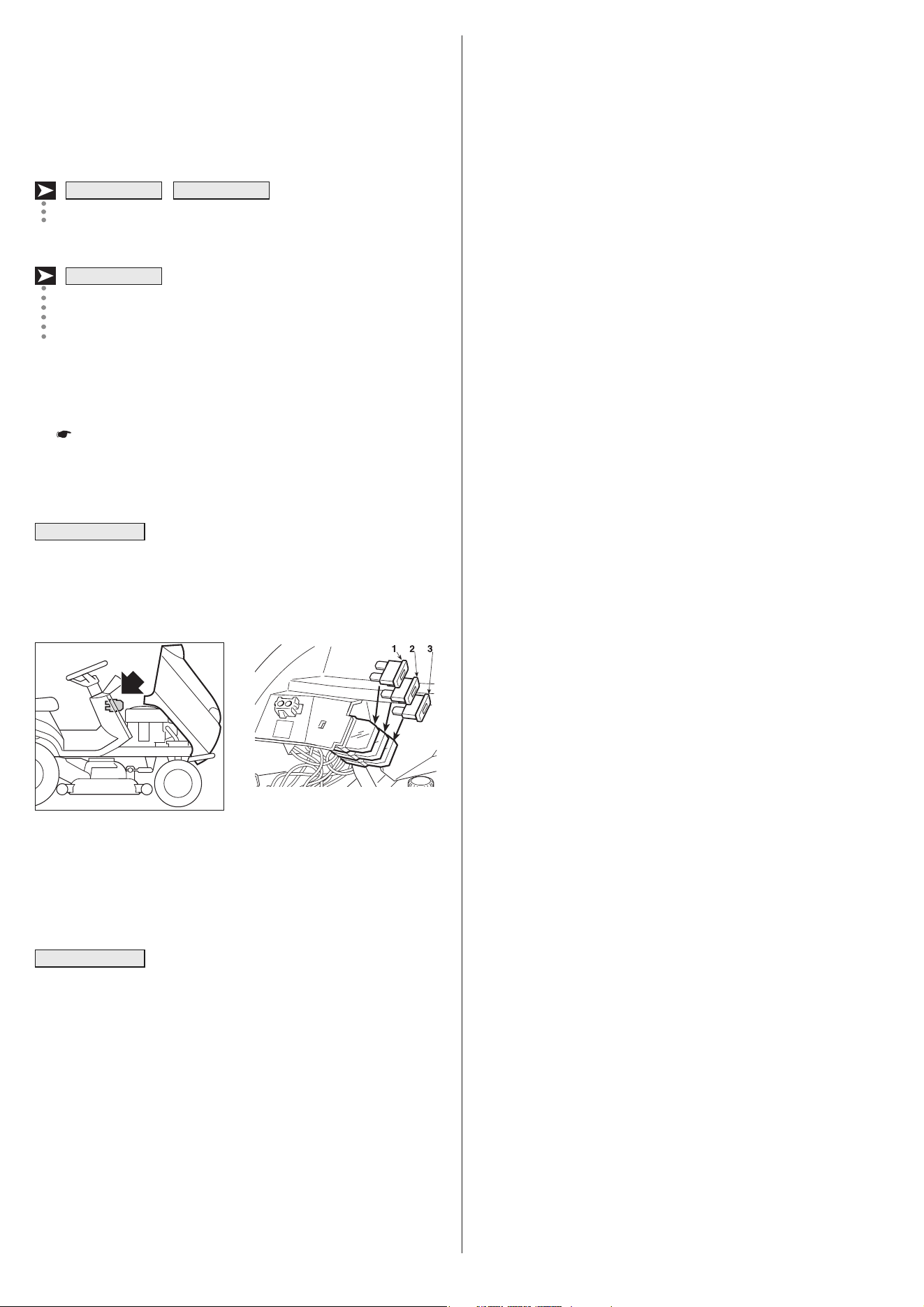
7. ENVIRONMENTAL PROTECTION
Environmental protection should be a priority of considerable im-
portance when using the machine, for the benefit of both social co-
existence and the environment in which we live.
– Try not to cause any disturbance to the surrounding area.
– Scrupulously comply with local regulations and provisions for the
disposal of waste materials after sawing.
– Scrupulously comply with local regulations and provisions for the
disposal of oils, petrol, damaged parts or any elements which
have a strong impact on the environment; this waste must not be
disposed of as normal waste, it must be separated and taken to
specified waste disposal centres where the material will be recy-
cled.
– At the time of decommissioning, do not pollute the environment
with the machine, hand it over to a disposal centre, in accordance
with the local laws in force.
22EN
6.4.9 Replacing a fuse
A few fuses of various capacities are envisaged on the machine.
Their functions and features are given in the following table:
1 - 10 Amps - (Red) protection of the main circuits
and power circuits of the
electronic card;
2 - 15 Amps - (Blue) protection of the recharge
circuit;
2 - 25 Amps - (White) protection of the recharge
circuit;
3 - 10 Amps - (Red) protection of the grass-catcher
tipping control circuit.
– When the fuse blows (1) the machine stops and all the lights on
the dashboard go out.
– The battery pilot lamp turns on in models provided with it
( 4.10.f) when the fuse (2) trips.
– Tripping of the fuse (3) prevents the control motor of the grass-
catcherʼs tipping to operate.
A blown fuse must always be replaced by one of
the same type and rating, and never with one of another rating.
If you cannot find eliminate the causes of the tripping, consult your
Dealer.
6.4.10 Replacing belts
Replacing belts is quite a complicated process of dismantling and
subsequent adjustment and must only be carried out by your Dealer.
Replace the belts as soon as they show obvious
signs of wear! ALWAYS USE GENUINE REPLACEMENT BELTS!
IMPORTANT
HF2620H••
HF23••◊•• HF24••◊••
NOTE
23 EN
8. TROUBLESHOOTING
PROBLEM LIKELY CAUSE SOLUTION
1. With the key at «ON» the dashboard
remains off with no audible signal
The protection of the electronic card has cut
in due to:
– badly connected battery
– battery terminals crossed
– completely flat battery or eroded
battery plates
– fuse blown
– bad earthing to the engine or the frame
Put the key in the «OFF» position and look for the cause of
the problem:
– check connections ( 3.4)
– check connections ( 3.4)
– recharge battery ( 6.2.3)
– replace fuse (10 A) ( 6.4.9)
– check connections of black earth leads
2. With the key at «ON» the dashboard
remains off, but there is an audible
signal (continuous).
The protection of the electronic card has cut
in due to:
– electronic card wet
Put the key in the «OFF» position and look for the cause of
the problem:
– dry using tepid air
3. With the key on «START» the
dashboard comes on but the starter
motor does not runa
– insufficiently charged battery
– badly earthed starter motor
– you are not ready for starting ( 5.2)
– recharge the battery ( 6.2.3)
– check earth connections
– disengage the blades
(if the problem continues, check the relevant micro-switch)
– put the transmission in neutral (N)
4. With the key on «START» the starter
motor runs but the engine does not start
– insufficiently charged battery
– faulty fuel supply
– faulty ignition
– no oil
– recharge the battery ( 6.2.3)
– check the level in the tank ( 5.3.3)
– check the wiring of the fuel open command
– check fuel filter ( 6.4.4)
– check that spark plug caps are firmly fitted ( 6.4.5)
– check that the electrodes are clean and have the correct
gap ( 6.4.5)
– check the engine oil level and top up if necessary
( 5.3.3).
5. Starting is difficult or the engine runs
erratically
– fault in carburation – clean or replace the air filter ( 6.4.3)
– flush out the float chamber ( 5.4.12)
– empty fuel tank and refill with fresh fuel ( 5.4.12)
– check and, if necessary, replace fuel filter ( 6.4.4)
6. Weak engine performance during
cutting
– forward speed too high in relation to
cutting height ( 5.4.5)
– reduce the forward speed and/or raise the cutting deck
7. Engine stops when blades are
engaged
– you are not ready to engage the blades
( 5.2)
– sit firmly on the seat
(if problem continues, check micro-switch)
– check that the grass-catcher or stone-guard are correctly in
position (if problem continues, check micro-switch)
8. The battery warning light does not
turn off after a few minutesʼ work
– recharging of the battery insufficient – check connections
9. The oil warning light comes on while
working
– problems in lubricating the engine Turn the key immediately to «STOP»
– top up the oil level ( 5.3.3)
– replace the filter (if the problem continues, contact your
Dealer
10. The engine stops and an audible
signal is heard
The protection of the electronic card has cut
in due to:
– battery contains electrolyte but is not
charged
– overvoltage caused by the charge
regulator
– badly connected battery (poor contact)
– engine badly earthed
Turn the key to «STOP» and look for the cause of the
problem:
– recharge battery ( 6.2.3)
– contact your Dealer
– check connections i ( 3.4)
– check engine earth connection
11. The engine stops with no audible
warning
– battery disconnected
– no earth contact on engine
– problems in the engine
– check connections ( 3.4)
– check the earth connection on the engine
– contact your Dealer
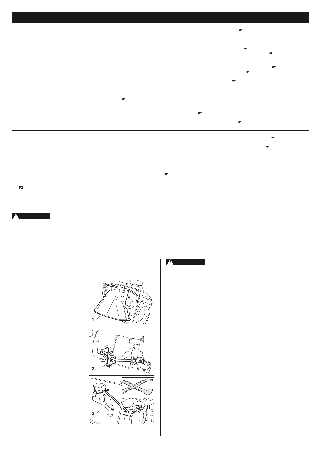
24EN
9. ACCESSORIES (OPTIONAL)
1. STONE-GUARD KIT
80092-VK1-003
For use in place of the grass-cat -
cher when the cuttings are not to
be collected.
2. TOWING HITCH
80596-VK1-003
For towing a small trailer.
3. MULCHING PLUG
HF2315: 80597-VK1-003
HF2417: 06805-VK1-A10
HF2620: 06805-VK1-B10
It finely chops the grass cuttings
and leaves them on the lawn, in-
stead of collecting them in the
grass-catcher.
For your safety, it is strictly prohibited to in-
stall any other attachment than the ones listed above and es-
pecially designed for your machine model and type.
WARNING!
PROBLEM LIKELY CAUSE SOLUTION
12. The blades do not engage – belt loosened
– problems in the electromagnetic clutch
– turn the adjusting nut ( 6.3.3)
– contact your Dealer
13. Uneven cut and poor grass
collection
– cutting deck not parallel to the ground
– blade cutting badly
– forward speed too high compared to height
of grass ( 5.4.5)
– collector channel is blocked
– cutting deck full of grass
– check the tyre pressures ( 5.3.2)
– re-align the cutting deck to the ground ( 6.3.2)
– check that the blades are fitted properly ( 6.3.1)
– sharpen or fit new blades ( 6.3.1)
– check the tension of the belt and control cable of the blade
engagement lever ( 6.3.3)
– reduce forward speed and/or raise the cutting deck
– wait for the grass to dry
– remove the grass-catcher and empty the collector channel
( 5.4.7)
– clean the cutting deck( 5.4.10)
14. Unusual vibrations while working – the blades are imbalanced
– blades loose
– fixing bolts loose
– balance or replace the damaged blades ( 6.3.1)
– check that the blades are firmly fitted ( 6.3.1)
(remember the left-hand thread of the right hand blade)
– check and tighten all the fixing bolts of the engine and
frame
15. With the engine running, the ma-
chine does not move when the drive
pedal is pressed
( f
or hydrostatic drive models)
– disengage lever in positon «B» ( 4.33) – put into position «A»
If problems continue after having carried out these operations, contact your Dealer.
Do not take on complicated repair work if you don't have the necessary equipment and the technical knowledge.
The guarantee is automatically revoked and the manufacturer declines all responsibility for any repairs which are badly done.
WARNING!

25 EN
MODELS HF2315SB• HF2315HM• HF2417HM• HF2417HT• HF2620HM• HF2620HT•
Function Cutting of grass
Electric system 12 V 12V 12 V 12 V 12 V 12 V
Battery 24 Ah 24 Ah 24 Ah 24 Ah 24 Ah 24 Ah
Engine: HONDA type GCV520 GCV520 GCV530 GCV530 GXV620 GXV620
Net Engine Power (*) 9.8 kW / 3600 9.8 kW / 3600 11.3 kW / 3600 11.3 kW / 3600 13.3 kW / 3600 13.3 kW / 3600
Nominal Engine Power 9.4 kW / 2800 9.4 kW / 2800 9.9 kW / 2800 9.9 kW / 2800 11.9 kW / 2800 11.9 kW / 2800
Operating engine speed 2800 r.p.m. 2800 r.p.m. 2800 r.p.m. 2800 r.p.m. 2800 r.p.m. 2800 r.p.m.
Front tyres 13 x 5.00-6 13 x 5.00-6 15 x 6.00-6 15 x 6.00-6 15 x 6.00-6 15 x 6.00-6
Rear tyres 18 x 8.50-8 18 x 8.50-8 18 x 8.50-8 18 x 8.50-8 18 x 8.50-8 18 x 8.50-8
Front tyres pressure 1.5 bar 1.5 bar 1.0 bar 1.0 bar 1.0 bar 1.0 bar
Rear tyres pressure 1.2 bar 1.2 bar 1.2 bar 1.2 bar 1.2 bar 1.2 bar
Fuel tank capacity 5.4 liters 5.4 liters 5.4 liters 5.4 liters 5.4 liters 5.4 liters
Weight 210 kg 213 kg 228 kg 237 kg 245 kg 254 kg
Forward speed
in Forward drive – 0 - 8.2 km/h 0 - 8.2 km/h 0 - 8.2 km/h 0 - 8.2 km/h 0 - 8.2 km/h
in 1.
st
2.1 km/h – – – – –
in 2.
nd
3.5 km/h – – – – –
in 3.
rd
5.4 km/h – – – – –
in 4.
th
6.0 km/h – – – – –
in 5.
th
9.0 km/h – – – – –
in reverse 2.6 km/h 0 - 4.2 km/h 0 - 4.2 km/h 0 - 4.2 km/h 0 - 4.2 km/h 0 - 4.2 km/h
Inside turning circle left inside 1.8 m 1.8 m 1.8 m 1.8 m 1.6 m 1.6 m
Cutting height 30 ÷ 80 mm 30 ÷ 80 mm 30 ÷ 90 mm 30 ÷ 90 mm 30 ÷ 90 mm 30 ÷ 90 mm
Cutting width 91 cm 91 cm 101 cm 101 cm 121 cm 121 cm
Grass-catcher capacity 280 liters 280 liters 300 liters 300 liters 350 liters 350 liters
Dimensions (mm)
A 1150 1150 1150 1150 1150 1150
B 835 835 880 880 880 880
C 855 855 950 950 950 950
D 1790 1870 1870 1870 1870 1870
E 2400 2480 2480 2480 2480 2480
F 960 960 1050 1050 1260 1260
G 980 980 990 990 990 990
H 1110 1110 1120 1120 1120 1120
10. SPECIFICATIONS
(*) The power rating of the engine indicated in this document is the net po -
wer output tested on a production engine for the engine models GCV520,
GCV530 and GXV620 and and measured in accordance with SAE J1349
at 3600 r.p.m. (Net Power) and at 2800 r.p.m. (Net Torque). Mass produc-
tion engines may vary from this value. Actual power output for the engine in-
stalled in the final machine will vary depending on numerous factors, including
the operating speed of the engine in application, environmental conditions,
maintenance, and other variables.
MODELS HF2315SB• HF2315HM• HF2417HM• HF2417HT• HF2620HM• HF2620HT•
Guaranteed acoustic power level
(2000/14/EC, 2005/88/EC)
dB(A) 100 100 100 100 105 105
Measured acoustic power level
(2000/14/EC, 2005/88/EC)
Measuring uncertainty
dB(A)
dB(A)
99
0.6
99
0.6
99
0.5
99
0.5
104
0.7
104
0.7
Sound pressure level at the ear
(EN836:1997 / AC:2006)
Measuring uncertainty
dB(A)
dB(A)
85
0.6
85
0.6
85,1
0.5
8,1
0.5
90
0.9
90
0.9
Real measured value of
acceleration on seat (EN 1032)
Measuring uncertainty
m/sec
2
m/sec
2
0.7
0.3
0.7
0.3
0.35
0.1
0.35
0.1
0.5
0.15
0.5
0.15
Real value of acceleration
on steering wheel (EN836:1997 /
AC:2006)
Measuring uncertainty
m/sec
2
m/sec
2
2.5
0.6
2.5
0.6
2.8
0.6
2.8
0.6
5.1
1.4
5.1
1.4
Maximum noise and vibration levels

26EN
Accelerator
Function and use ................................................................. 4.3
Audible warning
Function ......................................................................... 4.10-m
When it signals .................................................... 5.4.6 - 5.4.12
Battery
Description ....................................................................... 2.2-7
Connections ......................................................................... 3.5
Prolonged lack of use ..................................................... 5.4.12
Maintenance and recharge ............................................... 6.2.3
Blades
Description ....................................................................... 2.2-2
Engagement ........................................................................ 4.8
Dismantling and sharpening .......................................... 6.3.1-b
Adjusting the engagement ................................................ 6.3.3
Brake
Function of the pedal ......................................................... 4.31
Checking its effectiveness ................................................ 5.3.4
Using the brake ................................................................ 5.4.3
Adjusting ........................................................................... 6.3.4
Choke
Function and use ................................................................. 4.2
Clutch / Brake
Function of the pedal ......................................................... 4.21
Cleaning
How it is to be done ........................................................ 5.4.11
Collector channel
Description ....................................................................... 2.2-3
Unblocking ........................................................................ 5.4.7
Cutting deck
Description ....................................................................... 2.2-1
Internal washing .............................................................. 5.4.11
Removal ........................................................................ 6.3.1-a
Alignment .......................................................................... 6.3.2
Drive pedals
Function of the pedals ............................................. 4.32 - 4.33
Forward movement ........................................................... 5.4.2
Reverse movement .......................................................... 5.4.4
Drive to the wheels
Adjusting the belt .............................................................. 6.3.5
Engine
Engine oil ........................................................................... 6.4.1
Oil filter ............................................................................... 6.4.2
Air filter ............................................................................... 6.4.3
Fuel filter ............................................................................ 6.4.4
Spark plug .......................................................................... 6.4.5
Filling with oil and fuel
How to do so ..................................................................... 5.3.3
Fuse
Replacement .................................................................... 6.4.9
Grass-catcher
Description ....................................................................... 2.2-4
Tipping controls ................................................................... 4.9
Assembly ............................................................................. 3.9
Fitting on the machine ...................................................... 5.3.5
Emptying ........................................................................... 5.4.6
Adjusting the hooking ....................................................... 6.3.6
Key
Function ............................................................................... 4.4
Lights
Control ............................................................................. 4.10-l
Replacing bulbs ................................................................ 6.4.8
Maintenance
How it is to be done ............................................... 6.2.1 - 6.2.2
Mowing
Adjusting height ................................................................... 4.6
In reverse ............................................................................. 4.7
How to cut ......................................................................... 5.4.5
At the end of mowing ........................................................ 5.4.9
Advice for mowing ............................................................... 5.7
Mulching function .............................................................. 5.4.8
Parking brake
Function of the lever ............................................................ 4.5
Pilot lamps
Function ............................................................................. 4.10
When they light ............................................................... 5.4.13
Safety
General regulations ............................................................. 1.2
Decals with icons ................................................................. 1.3
When safety devices cut in .................................................. 5.2
Checking efficiency ........................................................... 5.3.5
Seat
Description ....................................................................... 2.2-8
Fitting on the machine ......................................................... 3.3
Adjustment ........................................................................ 5.3.1
Speed change
Position of the lever ........................................................... 4.22
Forward movement ........................................................... 5.4.2
Reverse movement .......................................................... 5.4.4
Slopes
Precautions when using ...................................................... 5.5
Starting
Procedure for starting ....................................................... 5.4.1
Steering wheel
Function ............................................................................... 4.1
Fitting onto the machine ...................................................... 3.2
Stone-guard
Description ....................................................................... 2.2-5
Fitting onto the machine ................................................... 5.3.5
Towing
Regulations .......................................................................... 1.4
Transport
How it is to be done ............................................................. 5.6
Tyres
Pressures ......................................................................... 5.3.2
Repair and replacement ................................................... 6.4.7
Wheels
Replacement .................................................................... 6.4.1
11. ALPHABETICAL INDEX

Major Honda distributor addresses
Adresses des principaux concessionnaires Honda
Adressen derwichtigsten Honda-Haupthändler
Elenco dei maggiori distributori Honda in Europa
Adressen van Honda-importeurs
Direcciones de los principales concesionarios Honda
FRANCE
Honda Relations Clients
TSA 80627
Tel. 02 38 81 33 90
45146 St Jean de la Ruelle Cedex
Fax. 02 38 81 33 91
http://www.honda-fr.com
NORWAY
Berema AS
P.O. Box 454
1401 Ski
Tel. : +47 64 86 05 00
Fax : +47 64 86 05 49
http://www.berema.no
(Canary Islands)
SPAIN & LAS PALMAS
PROVINCE
Greens Power Products, S.L.
Avda. Ramon Ciurans, 2
08530 La Garriga - Barcelona
Tel. : +34 3 860 50 25
Fax : +34 3 871 81 80
http://www.hondaencasa.com
GERMANY
Honda Motor Europe (North) GmbH
Sprendlinger Landstraße 166
63069 Offenbach am Main
Tel. : +49 69 8309-0
Fax : +49 69 8320 20
http://www.honda.de
POLAND
Aries Power Equipment Sp. z o.o.
ul. Wroclawska 25
01-493 Warszawa
Tel. : +48 (22) 861 43 01
Fax : +48 (22) 861 43 02
http://www.ariespower.pl - www.mojahonda.pl
SWEDEN
Honda Nordic AB
Box 50583 - Västkustvägen 17
20215 Malmö
Tel. : +46 (0)40 600 23 00
Fax : +46 (0)40 600 23 19
http://www.honda.se
GREECE
General Automotive Co S.A.
71 Leoforos Athinon
10173 Athens
Tel. : +30 210 3497809
Fax : +30 210 3467329
http://www.honda.gr
PORTUGAL
Honda Portugal, S.A.
Rua Fontes Pereira de Melo 16
Abrunheira, 2714-506 Sintra
Tel. : +351 21 915 53 33
Fax : +351 21 915 23 54
http://www.honda.pt
SWITZERLAND
Honda Suisse S.A.
10, Route des Moulières
1214 Vernier - Genève
Tel. : +41 (0)22 939 09 09
Fax : +41 (0)22 939 09 97
http://www.honda.ch
HUNGARY
Motor.Pedo Co., Ltd.
Kamaraerdei út 3.
2040 Budaors
Tel. : +36 23 444 971
Fax : +36 23 444 972
http://www.hondakisgepek.hu
REPUBLIC OF BELARUS
Scanlink Ltd.
Kozlova Drive, 9
220037 Minsk
Tel. : +375 172 999090
Fax : +375 172 999900
http://www.hondapower.by
TENERIFE PROVINCE
(Canary Islands)
Automocion Canarias S.A
Carretera General del Sur, KM 8.8
38107 Santa Cruz de Tenerife
Tel. : 34 (922) 620 617
Fax : 34 (922) 618 042
http://www.aucasa.com
ICELAND
Bernhard ehf.
Vatnagardar 24-26
104 Reykdjavik
Tel. : +354 520 1100
Fax : +354 520 1101
http://www.honda.is
ROMANIA
Hit Power Motor Srl
Calea Giulesti N° 6-8 - Sector 6
060274 Bucuresti
Tel. : +40 21 637 04 58
Fax : +40 21 637 04 78
http://www.honda.ro
TURKEY
Anadolu Motor Uretim ve
Pazarlama AS
Esentepe mah. Anadolu
Cad. No: 5
Kartal 34870 Istanbul
Tel. : +90 216 389 59 60
Fax : +90 216 353 31 98
http://anadolumotor.com.tr
IRELAND
Two Wheels Ltd.
M50 Business Park, Ballymount
Dublin 12
Tel. : +353 1 4381900
Fax : +353 1 4607851
http://www.hondaireland.ie
RUSSIA
Honda Motor RUS LLC
21, MKAD 47 km., Leninsky district.
Moscow region, 142784 Russia
Tel. : +7 (495) 745 20 80
Fax : +7 (495) 745 20 81
http://www.honda.co.ru
UKRAINE
Honda Ukraine LLC
101 Volodymyrska Str. Build. 2
Kyiv 01033
Tel. : +380 44 390 14 14
Fax. : +380 44 390 14 10
htpp://www.honda.ua
ITALY
Honda Italia Industriale S.p.A.
Via della Cecchignola, 5/7
00143 Roma
Tel. : +848 846 632
Fax : +39 065 4928 400
http://www.hondaitalia.com
SERBIA & MONTENEGRO
Bazis Grupa d.o.o.
Grcica Milenka 39
11000 Belgrade
Tel. : +381 11 3820 295
Fax : +381 11 3820 296
http://www.hondasrbija.co.rs
UNITED KINGDOM
Honda (UK) Power Equipment
470 London Road
Slough - Berkshire, SL3 8QY
Tel. : +44 (0)845 200 8000
http://www.honda.co.uk
MALTA
The Associated Motors
Company Ltd.
New Street in San Gwakkin Road
Mriehel Bypass, Mriehel QRM17
Tel. : +356 21 498 561
Fax : +356 21 480 150
SLOVAK REPUBLIC
Honda Slovakia, spol. s r.o.
Prievozská 6 - 821 09 Bratislava
Tel. : +421 2 32131112
Fax : +421 2 32131111
http://www.honda.sk
NETHERLANDS
Honda Motor Europe (North)
Afd. Power Equipment-Capronilaan 1
1119 NN Schiphol-Rijk
Tel. : +31 20 7070000
Fax : +31 20 7070001
http://www.honda.nl
SLOVENIA
AS Domzale Moto Center D.O.O.
Blatnica 3A
1236 Trzin
Tel. : +386 1 562 22 42
Fax : +386 1 562 37 05
http://www.as-domzale-motoc.si
AUSTRIA
Honda Motor Europe (North)
Hondastraße 1
2351 Wiener Neudorf
Tel. : +43 (0)2236 690 0
Fax : +43 (0)2236 690 480
http://www.honda.at
BALTIC STATES
(Estonia / Latvia / Lithuania)
Honda Motor Europe Ltd.
Estonian Branch
Tulika 15/17
10613 Tallinn
Tel. : 372 6801 300
Fax : 372 6801 301
BELGIUM
Honda Motor Europe (North)
Doornveld 180-184
1731 Zellik
Tel. : 32 2620 10 00
Fax : 32 2620 10 01
http://www.honda.be
BULGARIA
Kirov Ltd.
49 Tsaritsa Yoana blvd
1324 Sofia
Tel. : +359 2 93 30 892
Fax : +359 2 93 30 814
http://www.kirov.net
CROATIA
Hongoldonia d.o.o.
Jelkovecka Cesta 5
10360 Sesvete – Zagreb
Tel. : +385 1 2002053
Fax : +385 1 2020754
http://www.hongoldonia.hr
CYPRUS
Alexander Dimitriou & Sons Ltd.
162 Yiannos Kranidiotis Avenue
2235 Latsia, Nicosia
Tel. : + 357 22 715 300
Fax : + 357 22 715 400
CZECH REPUBLIC
BG Technik cs, a.s.
U Zavodiste 251/8
15900 Prague 5 - Velka Chuchle
Tel. : +420 2 838 70 850
Fax : +420 2 667 111 45
http://www.honda-stroje.cz
DENMARK
Tima Products A/S
Tårnfalkevej 16
2650 Hvidovre
Tel. : +45 36 34 25 50
Fax : +45 36 77 16 30
http://www.tima.dk
FINLAND
OY Brandt AB.
Tuupakantie 7B
01740 Vantaa
Tel. : +358 207757200
Fax : +358 9 878 5276
http://www.brandt.fi
i
EC-Declaration of Conformity
1) The undersigned, Mr Takayoshi Fukai, representing the manufacturer,
herewith declares that the machinery described below complies with all
the relevant provisions of the Machinery Directive 2006/42/EC, 98/37/EC.
The machinery also complies with the provisions of the:
- Outdoor noise Directive: 2000/14/EC, 2005/88/EC
- EMC Directive: 2004/108/EC
2) Description of the machinery:
a) Generic denomination: Lawn mower
b) Function: Cutting of grass
c) Type: HF2315K1 (SBE, SBF) - HF2315K1 (HME, HMF)
HF2417K2 (HME, HMF) - HF2417K2 (HTE, HTF)
HF2620K1 (HME, HMF) - HF2620K1 (HTE, HTF)
d) Serial number:
3) Outdoor noise Directive
a) Measured sound power: 99.8 dB(A) (HF2315K1, HF2417K2)
104 dB(A) (HF2620K1)
b) Guaranteed sound power: 100 dB(A) (HF2315K1, HF2417K2)
105 dB(A) (HF2620K1)
Déclaration CE de conformité
1
) Le soussigné, Mr Takayoshi Fukai, représentant du constructeur, déclare par la présente que
la machine décrite ci-dessous est conforme aux dispositions de la Directive Machine. Cette
machine répond également aux dispositions de :
- Directive relative aux émissions sonores dans l'environnement des matériels destinés
à être utilisés à l'extérieur des bâtiments :
- Directive relative à la compatibilité électromagnétique des équipements électriques
et électroniques :
2) Description de la machine
:
a) Dénomination générique : Tondeuse à gazon b) Fonction : Couper de l'herbe
c) Type : d) Numéro de série :
3)
Directive relative aux émissions sonores dans l'environnement des matériels destinés à être
utilisés à l'extérieur des bâtiments
:
a) Puissance acoustique mesurée b) Puissance acoustique garantie c) Paramètres de bruit:
Puissance nette installée d) Procédure d'évaluation de la conformité e) Organisme notifié.
4) Constructeur :
5) Représentant autorisé à valider la documentation technique :
6) Référence aux normes harmonisées :
7) Autres normes et spécifications techniques nationales:
Fait à: Date : Président : Signature :
EC - Prohlášení o shodƟ
1) Zástupce výrobce, Takayoshi Fukai svým podpisem potvrzuje, že daný výrobek splĖuje
požadavky SmƟrnice pro strojní zaĜízení Daný výrobek rovnƟž splĖuje požadavky následujících
SmƟrnic:
- Hluková smƟrnice:
- SmƟrnice pro elektromagnetickou kompatibilitu:
2) Popis zaĜízení:
a) Všeobecné oznaþení: Sekaþky na trávu b) Funkce: Sekání trávy
c) Typ: d) Výrobní císlo:
3) Hluková smƟrnice:
a) NamƟĜený akustický výkon - b) Garantovaný akustický výkon
c) Parametry: Nominální výkon - d) ZpĤsob stanovení shody - e) Notifikovaná osoba:
4) Výrobce:
5) Autorizovaná osoba povƟĜená schvalováním technické dokumentace:
6) Odkazy na harmonizované normy:
7) Ostatní použité národní normy a specifikace:
Podepsáno v: Datum: Prezident: Podpis:
EU Overenstemmelseerklæring
1) Undertegnede,Takayoshi Fukai, som repræsenterer producenten erklærer herved, at produktet
beskrevet nedenfor opfylder alle retningslinier i maskindirektivet. Produktet opfylder også
bestemmelserne i:
- Direktiv om støjemission fra maskiner til udedørs brug:
- EMC direktiv:
2) Beskrivelse af produktet:
a) Fællesbetegnelse: Plæneklipper b) Anvendelse: Græsklipning c) Type: d) Stelnummer:
3) Direktiv om støjemission fra maskiner til udedørs brug:
a) Målt støjniveau - b) Garanteret støjniveau - c) Støjparameter: Installeret motoreffekt
d) Overenstemmelsens vurderingsprocedure - e) Bemyndiget organ
4) Producent:
5) Autoriseret repræsentant for udfærdigelsen af den tekniske dokumentation:
6) Reference til harminiserede standarder:
7) Andre nationale standarder eller specifikationer:
Sted: Dato: Formand: Underskrift:
EÜ Vastavusavaldus
1) Allakirjutanu,Takayoshi Fukai, kinnitab tootja volitatud esindajana, et alltoodud seadmed
vastavad kõikidele Tehniliste seadmete direktiivinõuetele. Lisaks selle vastavad seadmed
järgmiste direktiivide nõuetele:
- Müratase välitingimustes:
- EMC direktiiv:
2) Seadmete kirjeldus:
a) Üldnimetus: Muruniiduk b) Funktsiooon: Muru niitmine c) Tüüp: d) Seerianumber:
3) Müratase välitingimustes:
a) Mõõdetav helivõimsuse tase - b) Tegelik helivõimsuse tase - c) Müra mõjutavad tegurid: Toite
võimsus - d) Vastavushindamise menetlus - e) Teavitatud asutus
4) Tootja:
5) Volitatud esindaja, kes on kvalifitseeritud koostama tehnilist dokumentatsiooni:
6) Viide ühtlustatud standarditele:
7) Siseriiklikud seadusaktid:
Koht: Kuupäev: President: Allkiri:
EC - Ⱦɟɤɥɚɪɚɰɢɹ ɡɚ ɫɴɨɬɜɟɬɫɬɜɢɟ
1) Ⱦɨɥɭɩɨɞɩɢɫɚɥɢɹɬ ɫɟ Ƚ-ɧ Ʉɚɧɟɦɭɪɚ, ɩɪɟɞɫɬɚɜɥɹɜɚɳ ɩɪɨɢɡɜɨɞɢɬɟɥɹ, ɫ ɧɚɫɬɨɹɳɢɹ
ɞɨɤɭɦɟɧɬ ɞɟɤɥɚɪɢɪɚ ɱɟ ɦɚɲɢɧɚ ɨɩɢɫɚɧɚ ɩɨ-ɞɨɥɭ ɟ ɜ ɫɴɨɬɜɟɬɫɬɜɢɟ ɫ ɜɫɢɱɤɢ ɢɡɢɫɤɜɚɧɢɹ ɧɚ
ɞɢɪɟɤɬɢɜɢɬɟ ɡɚ ɦɚɲɢɧɢ ɢ ɫɴɨɪɴɠɟɧɢɹ - ɋɴɨɪɴɠɟɧɢɟɬɨ ɫɴɳɨ ɫɴɨɬɜɟɬɫɬɜɚ ɫ ɢɡɢɫɤɜɚɧɢɹɬɚ
ɧɚ:
- Ⱦɢɪɟɤɬɢɜɚ ɡɚ ɧɢɜɨɬɨ ɧɚ ɲɭɦɚ: - EMC ɞɢɪɟɤɬɢɜɚ:
2) Ɉɩɢɫɚɧɢɟ ɧɚ ɨɛɨɪɭɞɜɚɧɟɬɨ:
ɚ) Ɉɛɳɨ ɧɚɢɦɟɧɨɜɚɧɢɟ: ɤɨɫɚɱɤɚ ɛ) Ɏɭɧɤɰɢɹ: ɤɨɫɟɧɟ ɧɚ ɬɪɟɜɚ
ɜ) Ɍɢɩ: ɞ) ɋɟɪɢɟɧ ɧɨɦɟɪ:
3) ȼɴɧɲɟɧ ɲɭɦ:
ɚ) ɢɡɦɟɪɟɧɚ ɫɢɥɚ ɧɚ ɡɜɭɤɚ - b) ɦɚɤɫɢɦɚɥɧɚ ɫɢɥɚ ɧɚ ɡɜɭɤɚ - c) ɩɚɪɚɦɟɬɪɢ ɧɚ ɲɭɦɚ;
ɧɟɬɧɚ ɢɧɫɬɚɥɢɪɚɧɚ ɦɨɳɧɨɫɬ - d) ɩɪɨɰɟɞɭɪɚ ɧɚ ɢɡɦɟɪɜɚɧɟɬɨ - e) ɢɡɦɟɪɟɧɨ ɧɚ ɤɭɩɟ
4) ɉɪɨɢɡɜɨɞɢɬɟɥ:
5) Ɉɬɨɪɢɡɢɪɚɧ ɩɪɟɞɫɬɚɜɢɬɟɥ, ɤɨɣɬɨ ɦɨɠɟ ɞɚ ɫɴɫɬɚɜɹ ɬɟɯɧɢɱɟɫɤɚɬɚ ɞɨɤɭɦɟɧɬɚɰɢɹ:
6) ɋɴɨɬɜɟɬɫɬɜɢɟ ɫ ɯɚɪɦɨɧɢɡɢɪɚɧɢ ɟɬɚɧɞɚɪɬɢ:
7) Ⱦɪɭɝɢ ɧɚɰɢɨɧɚɥɧɢ ɫɬɚɧɞɚɪɬɢ ɢ ɫɩɟɰɢɮɢɤɚɰɢɢ:
Ɇɹɫɬɨ ɧɚ ɢɡɝɨɬɜɹɧɟ: Ⱦɚɬɚ ɧɚ ɢɡɝɨɬɜɹɧɟ: Ɇɟɧɢɞɠɴɪ
ɩɨ ɤɚɱɟɫɬɜɨ: ɉɨɞɩɢɫ:
EG-Konformitätserklärung
1) Der Unterzeichner,Takayoshi Fukai der den Hersteller vertritt, erklärt hiermit dass die unten
genannte Maschine den Bestimmungen aller relevanten Maschinenrichtlinien entspricht. Die
Maschine entspricht ebenfalls den Vorschriften der:
- Outdoor Richtlinie:
- EMV Richtlinie:
2) Beschreibung der Maschine
:
a) Allgemeine Bezeichnung: Rasenmäher b) Funktion: Gras schneiden
c) Typ: d) Seriennummer:
3) Richtlinie zu Geräuschemissionen im Freien:
a) Gemessener Schallleistungspegel - b) Garantierter Schallleistungspegel - c) Geräusch
Vorgabe: Tatsächliche Leistung - d) Angewandtes Konformitätsbewertungsverfahren
e) Benannte Stelle
4) Hersteller:
5) Bevollmächtigter zur Erstellung der technischen Unterlagen:
6) Verweis auf harmonisierte Normen:
7) Andere herangezogene nationale Normen, Bestimmungen oder Vorschriften:
Ort: Datum: Präsident: Unterschrift:
Declaracion de conformidad CE.
1) El firmante, Takayoshi Fukai, en representación del fabricante, adjunto declara que la máquina
descrita más abajo cumple con todas los requisitos relevantes de la Directiva de Maquinaria.
La máquina también cumple con los requisitos de la:
- Directiva sobre Ruido exterior: - Directiva EMC:
2) Descripción de la máquina:
a) Denominación genérica: Cortacésped b) Función: Cortar el césped
c) Tipo: d) Número serie:
3) Directiva Ruido Exterior:
a) Potencia medida sonido - b) Potencia sonido garantizada - c) Parámetros ruido:
Potencia neta instalada - d) Procedimiento valoración conformidad -
e) Organismo notificado.
4) Fabricante:
5) Representante autorizado para recopilar la Documentación Técnica:
6) Referencia de los estándar harmonizados:
7) Otros estándar nacionales o especificaciones:
Realizado en: Fecha: Presidente: Firma:
EU-vaatimustenmukaisuusvakuutus
1) Allekirjoittanut valmistajan edustaja Takayoshi Fukai vakuuttaa täten, että tuote on
kaikkien EU: n konedirektiivin vaatimusten mukainen. Tuote on lisäksi seuraavien
EU: n direktiivien vaatimusten mukainen:
- Meludirektiivi:
- Sähkömagneettista yhteensopivuutta koskeva direktiivi:
2)
Tuotteen kuvaus:
a) Yleisarvomäärä: Ruohonleikkuri b) Toiminto: Ruohon leikkaus
c) Tyyppi: d) Sarjanumero:
3)
Meludirektiivi:
a) Mitattu äänitehotaso - b) Taattu äänitehotaso - c) Meluparametrit: Asennettu nettoteho
d) Vaatimustenmukaisuuden arviointimenettely - e) Ilmoitettu laitos
4) Valmistaja:
5) Teknisen dokumentaation laatinut valmistajan edustaja:
6) Viittaus yhdenmukaistettuihin standardeihin:
7) Muut kansalliset standardit tai tekniset eritelmät:
Laadittu: Päivämäärä: Pääjohtaja: Allekirjoitus:
ȆȚıIJȠʌȠȚȘIJȚțȩ ıȣȝȝȩȡijȦıȘȢ Ǽ.Ǽ.
1) ȅ ȣʌȠȖȡȐijȦȞ,Takayoshi Fukai İțʌȡȠıȦʌȩȞIJĮȢ IJȠȞ țĮIJĮıțİȣĮıIJȒ, įȚĮ IJȠȣ ʌĮȡȩȞIJȠȢ
įȘȜȫȞİȚ ȩIJȚ IJȠ ȝȘȤȐȞȘȝĮ ʌȠȣ ĮȞĮijȑȡİIJĮȚ ʌȚȩ țȐIJȦ ȕȡȓıțİIJĮȚ ıİ İȞĮȡȝȩȞȚıȘ ȝİ IJȚȢ ʌȡȠȕȜȑȥİȚȢ
IJȦȞ ȠįȘȖȚȫȞ IJȘȢ ǼǼ. ȉĮ ȝȘȤĮȞȒȝĮIJĮ ȕȡȓıțȠȞIJĮȚ ıİ İȞĮȡȝȩȞȚıȘ ȝİ IJȚȢ ʌȡȠȕȜȑȥİȚȢ IJȦȞ:
- ȅįȘȖȚȫȞ șȠȡȪȕȠȣ İȟȦIJİȡȚțȠȪ ȤȫȡȠȣ:
- ȅįȘȖȓĮȢ EMC:
2)
ȆİȡȚȖȡĮijȒ ȝȘȤĮȞȒȝĮIJȠȢ:
Į) īİȞȚțȒ ȠȞȠȝĮıȓĮ: ȋȜȠȠțȠʌIJȚțȒ ȝȘȤĮȞȒ ȕ) ȁİȚIJȠȣȡȖȓĮ: ȖȚĮ țȩȥȚȝȠ ȖȡĮıȚįȚȠȪ
Ȗ) ȉȪʌȠ Ȣ: į) ǹȡȚșȝȩȢ ʌĮȡĮȖȦȖȒȢ:
3) ȅįȘȖȓĮ șȠȡȪȕȠȣ İȟȦIJİȡȚțȠȪ ȤȫȡȠȣ:
Į) ǿıȤȪȢ ȝİIJȡȘșȑȞIJȠȢ șȠȡȪȕȠȣ - ȕ) ǼȖȖȣȘȝȑȞȠ İʌȓʌİįȠ șȠȡȪȕȠȣ - Ȗ) ȆĮȡĮȝȑIJȡȠȚ șȠȡȪȕȠȣ:
ȚıȤȪȢ țȚȞȘIJȒȡĮ - į) ǻȚĮįȚțĮıȓĮ ĮȟȚȠȜȩȖȘıȘȢ ıȣȝȝȩȡijȦıȘȢ - İ) ǵȞȠȝĮ țȠȚȞȠʌȠȚȘȝȑȞȠȣ
ȠȡȖĮȞȚıȝȠȪ
4) ȀĮIJĮıțİȣĮıIJȒȢ:
5) ǼȖȖİțȡȚȝȑȞȠȢ ĮȞIJȚʌȡȩıȦʌȠȢ ȚțĮȞȩȢ ȖȚȐ ıȪıIJĮıȘ IJİȤȞȚțȠȪ ıȣȖȖȡȐȝȝĮIJȠȢ:
6) ǹȞĮijȠȡȐ ıİ İȞĮȡȝȠȞȚıȝȑȞĮ ʌȡȩIJȣʌĮ:
7) ǹȞĮijȠȡȐ ıİ ȐȜȜĮ İșȞȚțȐ ʌȡȩIJȣʌĮ Ȓ ʌȡȠįȚĮȖȡĮijȑȢ:
Ǿ
įȠțȚȝȒ ȑȖȚȞİ: ǾȝİȡȠȝȘȞȓĮ: ȆȡȩİįȡȠȢ: ȊʌȠȖȡĮijȒ:
EK-MegfelelĘségi nyilatkozat
1) Alulírott Takayoshi Fukai, mint a gyártó képviselĘje nyilatkozom, hogy az alábbi berendezés
mindenben megfelel a Gépekre irányuló rendelkezéseknek:
A berendezés megfelel a KülsĘ Hangkbocsátási és a EMC Direktíváknak
2) A gép leírása:
a) Általános megnevezés: FĦnyíró b) Funkció: FĦ levágása
c) Típus: d) Sorozatszám:
3) KülsĘ hangkibocsátási elĘírások:
a) Mért hangerĘ b) Garantált hangerĘ c) Zaj paraméter: Üzembehelyezett zajszint
d) Becslési eljárás megfelelĘsséghez e) Bejegyzett teszt
4) Gyártó:
5) MĦszaki dokumentáció összeállítására jogosult képviselĘ:
6) Hivatkozással a szabványokra:
7) Más belföldi elĘírások, megjegyzések:
Keltezés helye: Keltezés ideje: Elnök: Aláírás:
HF2315K1 SBE, SBF 2010001 to 2019999
HF2315K1 HME, HMF 2010001 to 2019999
HF2417K2 HME, HMF 2010001 to 2019999
HF2417K2 HTE, HTF 2010001 to 2019999
HF2620K1 HME, HMF 2010001 to 2019999
HF2620K1 HTE, HTF 2010001 to 2019999
ii
2)
2)
4) Manufacturer:
Honda France Manufacturing S.A.S.
Pôle 45 - Rue des Chataîgniers
45140 ORMES - FRANCE
.
5) Authorized Representative able to compile the technical
documentation
:
6)
Reference to harmonized standards
EN 836 : 1997 / AC : 2006
EN ISO 14982 : 1998
7)
Other national standards or specifications
Done at: Date: President: Signature:
ORMES 01 12 2009 Takayoshi Fukai
N/A
L = 91 cm (HF2315K1)
L = 101 cm (HF2417K2)
L = 121 cm (HF2620K1)
d) Conformity assessment procedure: Annex VI
e) Notified body:
TÜV RHEINLAND PRODUCT SAFETY GMBH
Am Grauen Stein - 51105 Köln
Germany
Declaração CE de conformidade
1
) O abaixo assinado, Takayoshi Fukai, representante do fabricante, declara que a maquinaria
abaixo descrita cumpre com todas as normas referentes á Directiva de Maquinaria. A
maquinaria também cumpre as directivas de:
- Directiva de ruído no exterior: - Directiva EMC:
2) Descrição da maquinaria
:
a) Denominação genérica: Corta-relvas b) Função: Corte de relva
c) Tipo: d) Número série:
3) Directiva de ruido no exterior
:
a) Potência de som medida - b) Potência de som garantida - c) Parâmetros de ruido:
d) Procedimento da avaliação da conformidade - e) Organismo notificado
4) Fabricante:
5) Representante autorizado e apto para confirmar a documentação técnica:
6) Referência aos padrões harmonizados:
7) Outras normas nacionais ou especificações:
Feito em: Data: Presidente: Assinatura:
Deklaracja zgodnoĞci wyrobu
1
) NiĪej podpisany, Takayoshi Fukai rezprezentujący producenta, deklaruje iĪ urządzenie
opisane poniĪej jest zgodne z wszystkimi zasadniczymi wymaganiami Dyrektywy
Maszynowej. Urządzenie spelnia dodatkowo wymagania:
- Dyrektywy Halasowej: - Dyrektywy EMC:
2) Opis urządzenia:
a) Ogólne okreĞlenie: Kosiarka b) Funkcja: ĝcinanie trawy c) Typ: d) Numery seryjne:
3) Dyrektywa Halasowa:
a) Zmierzony poziom mocy akustycznej - b) Gwarantowany poziom mocy akustycznej
c) Parametrycharakterystyczne: Zainstalowana moc netto
d) Zastosowana procedura oceny zgodnosci - e) Jednostka Notyfikowana
4) Producent:
5) UpowaĪniony Przedstawiciel posiadający dostĊp do dokumentacji technicznej:
6) Zastosowane normy zharmonizowane:
7) Pozostale normy i przepisy krajowe:
Miejsce: Data: Prezes: Podpis:
UE -Declaratie de Conformitate
1
)
Subsemnatul
Takayoshi Fukai,
reprezentand producatorul,declara prin prezenta ca
chipamentele mai descrise mai jos respecta toate prevederile relevante din Directiva privind
echipamentele Echipamentele respecta de-asemenea prevederile Directivei privind nivelul
de zgomot exterior si Directiva EMC:
2)
Descrierea echipamentului:
a)
Denumire generica: Cositoare gazon b) Domeniu de utilizare: Tunderea ierbii
c) Tip: d) Numar de serie:
3)
Directiva privind zgomotul exterior:
a)
Puterea sonora masurata: - b) Puterea sonora garantata: - c) Parametrii de zgomot
putere instalata neta - d) Procedura de evaluare a conformitatii: - e) Organismul notificat
4)
Producator:
5)
Reprezentantul Autorizat in masura sa intocmeasca documentatia tehnica:
6)
Referinta la standardele armonizate:
7)
Alte standarde nationale sau specificatii:
Emisa la:
Data:
Prezident:
Semnatura:
EG-deklaration för överensstämmande
1
)
Undertecknad,
Takayoshi Fukai,
representant för tillverkaren, försäkrar härmed att maskinerna
beskrivna nedan uppfyller alla relevanta stadgar i Maskin Direktivet eller Maskinerna uppfyller
också stadgarna för:
-
Utomhus bullerdirektiv: - EMC direktiv:
2)
Maskinbeskrivning:
a)
Allmän benämning: Gräsklippare b) Funktion: Gräsklippning c) Typ: d) Serie nummer:
3)
Utomhus bullerdirektiv:
a)
Uppmätt ljudeffekt - b) Garanterad ljudeffekt - c) Bullerparameter: Installerad nettoeffekt
d)
Utvärderingsprocedur för överensstämmande - e) Anmälda organ
4)
Tillverkare:
5)
Auktoriserad representant som kan sammanställa den tekniska dokumentationen:
6)
Referens till överensstämmande standarder:
7)
Andra nationella standarder eller specifikationer:
Utfärdat vid: Datum:
Ordförande:
Underskrift:
Vyhlásenie o súlade s predpismi ES
1
) Dolupodpísaný pán Takayoshi Fukai zastupujúci výrobcu týmto vyhlasuje, že stroje
popísané nižšie vyhovujú všetkým relevantným predpisom smernice Stroje vyhovujú
predpisom: - EMC direktiva:
2) Popis strojov:
a) Druhové oznaþenie: Kosaþky na trávu b) Funkcia: Kosenie trávy c) Typ: d) Sériové þíslo:
3) Smernica emisií hluku vo voĐnom priestranstve:
a) Nameraný akustický tlak - b) Garantovaný akustický tlak - c) Parameter hluku: Nominálny
þistý výkon - d) Proces posudzovania zhody - e) Notifikovaný orgán
4) Výrobca:
5) Autorizovaný zástupca schopný predložiĢ technickú dokumentáciu:
6) Referencia k harmonizovaným štandardom:
7) ĆaĐšie národné štandardy alebo špecifikácie:
Miesto: Dátum: Predseda: Podpis:
ES-Izjava o skladnosti
1
) Spodaj podpisani, Takayoshi Fukai, ki predstavljam proizvajalca, izjavljam da so spodaj
navedene naprave v skladu z direktivo Naprave prav tako ustrezajo naslednjim direktivam:
- Direktiva o hrupnosti: - EMC direktiva:
2) Opis naprav:
a) Vrsta stroja: Vrtne kosilnica b) Funkcija: Košenje trave c) Tip: d) Serijska številka:
3) Direktiva o hrupnosti:
a) Izmerjena zvocna moþ - b) Garantirana Žvoþna moþ - c) Parametri: neto moþ
d) Postopek meritve - e) Testiranja opravil
4) Proizvajalec:
5) Pooblašþeni predstavnik, ki hrani tehniþno dokumentacijo:
6) Upoštevani harmonizirani standardi:
7) Ostali standardi:
Kraj: Dátum: Predsednik: Podpis:
EU samsvarserklæring
1
) Undertegnede, Takayoshi Fukai representerer produsenten og erklærer herved at produktet
beskrevet nedenfor er i samsvar med relevante forskrifter i Maskindirektivet. Produktet
samsvarer også med forskrifter vedr:
- Rammedirektiv for utendørs støy: - EMC direktiv
2) Produktbeskrivelse
:
a) Felles benevnelse: Gressklipper b) Funksjon: Klippe gress c) Type: d) Serienummer:
3) Rammedirektiv om utendørs støy:
a) Målt lydeffekt - b) Garantert lydeffekt - c) Støyparameter: Netto installert effekt
d) Valgt samsvarsprosedyre - e) Teknisk kontrollorgan
4) Produsent:
5) Autorisert representant/innehaver av teknisk dokumentasjon:
6) Referanse til harmoniserte standarder:
7) Øvrige nasjonale standarder eller spesifikasjoner:
Sted: Dato: Formann: Underskrift:
EK AtbilstƯbas deklarƗcija
1
) ZemƗk minƝtais Takayoshi Fukai, kƗ ražotƗja pƗrstƗvis ar šo apstiprina, ka atrunƗtƗ iekƗrta
pilnƯbƗ atbilst visiem standartiem, kas atrunƗti EC-DirektƯvƗ KƗ arƯ šƯ iekƗrta atbilst:
- TrokšƼa lƯmeƼa direktƯvai:
- EMC direktƯvai:
2) LekƗrtas apraksts:
a) VispƗrƝjais nosukums: ZƗles pƺƗvƝjs b) Funkcija: ZƗles pƺaušana
c) Tips: d) SƝrijas numurs:
3) TrokšƼa lƯmeƼa direktƯva:
a) NomƝrƯtƗ trokšƼa jauda - b) GarantƝtƗ trokšƼa jauda - c) TrokšƼa parametri: KopƝjƗ
uzstƗdƯtƗ jauda - d) AtbilstƯbas noteikšanas procednjra - e) AtbildƯgƗ iestƗde
4) RažotƗjs:
5) AutorizƝtais pƗrstƗvis, kas ir kompetents apkopot tehnisko dokumentƗciju:
6) Atsaucoties uz saskaƼotajiem standartiem:
7) Citi valsts noteiktie standarti vai specifikƗcijas:
Vieta: Datums: Prezidents: Paraksts:
EU-Conformiteitsverklaring
1
) Ondergetekende, Takayoshi Fukai, vertegenwoordiger van de constructeur, verklaart hierbij
dat de hieronder beschreven machine in overeenstemming is met de bepalingen van de
Veiligheidsrichtlijn voor machines. De machine voldoet eveneens aan de bepalingen van de
richtlijnen voor geluidsemissie van materieel voor gebruik buitenshuis en elektromagnetisme
2) Beschrijving van de machine
:
a) Algemene benaming: Motorgazonmaaier b) Functie: Gras maaien
c) Type: d) Serienummer:
3) Geluidsemissie materieel voor gebruik buitenhuis:
a) Gemeten geluidsvermogen - b) Gegarandeerd geluidsvermogen -
c) Geluidsparameter: Gëinstalleerd vermogen -
d) Conformiteitsbeoordelingprocedure - e) In kennis gestelde instantie
4) Konstrukteur :
5) Vertegenwoordiger die gemachtigd is om de technische documentatie samen te stellen:
6) Verwijzing naar geharmoniseerde normen:
7) Andere nationale normen of technische specificaties:
Opgemaakt te: Datum: President: Handtening:
Dichiarazione di conformità
1
) Il sottoscritto,Takayoshi Fukai in rappresentanza del costruttore, dichiara qui di seguito che la
macchina sotto descritta è conforme con tutte le condizioni pertinenti della Direttiva
Macchine. La macchina è anche conforme alle condizioni della:
- Direttiva sulle emissioni acustiche delle macchine destinate a funzionare all'aria aperta:
- Direttiva sulla compatibilità elettromagnetica:
2) Descrizione della macchina:
a) Denominazione generica: Rasaerba b) Funzione: Taglio di erba
c) Tipo: d) Numero di serie:
3) Direttiva emissioni acustiche:
a) Livello di potenza sonora misurata - b) Livello di potenza sonora garantita
c) Parametri rumorosità: Potenza netta installata - d) Procedura di valutazione conformità
e) Organismo notificato
4) Costruttore:
5) Rappresentante Autorizzato idoneo a compilare la documentazione tecnica:
6) Riferimento agli standard armonizzati:
7) Altri standard o specifiche nazionali
Fatto a: Data: Presidente: Firma:
EB Atitikties Deklaracija.
1
) Žemiau pasirašes, p. Takayoshi Fukai atstovaujantis gamintoją, deklaruoja, kad Ƴranga
atitinka reikalavimus pagal direktyvą:
2) Mašinos aprašymas
:
a) Bendras pavadinimas: Vejapjovơ b) Funkcija: Žolès pjpvimas
c) Tipas: d) Serijinis numeris:
3) Triukšmo direktyva:
a) Išmatuotas riukšmo lygis - b) Garantuotas triukšmo lygis - c) Triukšmo parametrai:
Nominali instaliuota galia - d) Atitikties Ƴvertinimo procednjra - e) Atstovas.
4) Gamintojas:
5) Ʋgaliotas atstovas turintis techninĊ dokumentaciją:
6) Nuoroda Ƴ harmonizuotus standartus:
7) Kiti nacionaliniai standartai ir specifikacijos:
Atlikta: Data: Prezidentas: Parašas:
c) Noise parameter:
Honda France Manufacturing S.A.S.
Pôle 45 - Rue des Chataîgniers
45140 ORMES - FRANCE
iii

iv
RCS ORLÉANS B 501 736 565 171505502/0