
100
50
6
7
8
9
105
28
106
42
29
46
43
38
53
41
(5x)
1
(4x)
55
39
(2x)
54
110
45
40
56
41
(4x)
44
102
6 7
8 9
111
38 39 40
41 42 43
46 53 54
109
44
45
MILWAUKEE TOOL
l
www.milwaukeetool.com
13135 W. LISBON RD., BROOKFIELD, WI 53005
Drwg. 3
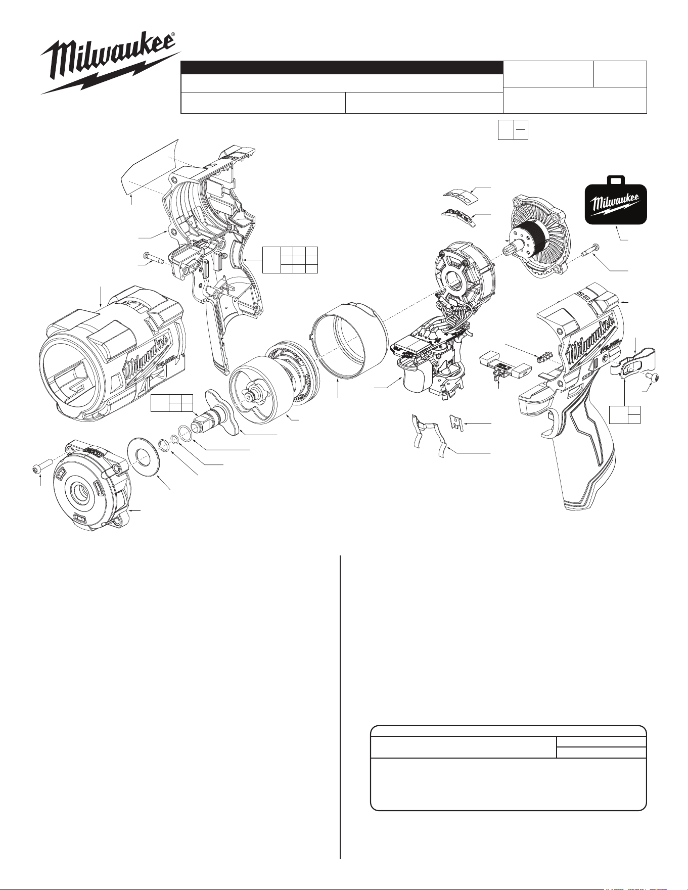
FIG. PART NO. DESCRIPTION OF PART NO. REQ.
1 05-74-7130 M4 x 16mm Pan Hd. T-20 Screw (4)
6 44-90-1050 3/8" Friction Ring (1)
7 34-40-1885 O-Ring (1)
8 --------------- O-Ring (1)
9 --------------- 3/8" Anvil (1)
28 45-22-0054 Rubber Sleeve (1)
29 45-24-0047 Forward/Reverse Shuttle (1)
38 --------------- Right Housing Halve - Cover (1)
39 23-28-0228 Mode Select Light Pipe (2)
40 --------------- Left Housing Halve - Support (1)
41 06-82-6351 M3 x 16mm Pan Hd. ST T-10 Screw (9)
42 42-70-0058 Housing Connection Clip (1)
43 42-70-0480 Leaf Spring (1)
44 --------------- #6-32 Pan Hd. T-15/Slot Screw (1)
45 --------------- Belt Clip (1)
46 23-28-0229 Fuel Gauge Light Pipe (1)
50 45-88-2554 Front Gear Case Washer (1)
53 12-20-1412 Service Nameplate (1)
54 10-22-1973 Trigger Mode Select Label (1)
55 49-16-2562 Rubber Boot (Optional, Accessory) (1)
56 42-55-3400 Zippered Tool Bag (1)
100 28-50-0916 3/8" Gear Case Assembly (1)
102 42-06-0321 3/8" Friction Ring Anvil Assembly (1)
105 14-30-1226 Impacting Assembly (1)
106 14-20-0249 Electronics Assembly (1)
109 42-70-0497 Belt Clip Service Kit (1)
110 16-01-2565 Rotor/Back Cap Assembly (1)
111 31-44-0316 Housing Service Kit (1)
EXAMPLE:
Component Parts (Small #)
Are Included When Ordering
The Assembly (Large #).
0
00
FIG. LUBRICATION
(Type 'J' Grease, No. 49-08-4220):
When servicing, remove 90-95% of the existing grease
prior to installing Type ‘J’. Original grease may be similar
in color but not compatible with ‘J’.
100 Coat anvil opening in the front of the gear case with grease.
102 Lightly coat round shaft surface of anvil with grease. Place a
dab of grease in cavity at rear of anvil.
105 Lightly coat the inside gear teeth of ring gear and ring gear
hole, surface of the hammer, and the gear teeth of the planet
gears of impacting assembly with grease.
110 Coat pinion of rotor/back cap assembly with grease.
SCREW TORQUE SPECIFICATIONS
SEAT TORQUE
FIG. PART NO. WHERE USED (kgf-cm) (lb-in)
1 05-74-7130 Front Gear Case 45±3 39±3
41 06-82-6351 Rotor/Back Cap 7±1 6±1
41 06-82-6351 Right Housing-Cover 10±1 9±1
44
---------------
Belt Clip 16±2 14±2
BULLETIN NO.
54-26-2575
SERVICE PARTS LIST
CATALOG NO. 2562-20
REVISED BULLETIN
SPECIFY CATALOG NO. AND SERIAL NO. WHEN ORDERING PARTS
M12 FUEL™ 3/8" Stubby Impact Wrench w/ Friction Ring
SERIAL NO.
DATE
Sept. 2025
WIRING INSTRUCTION
P49A
See Page 2
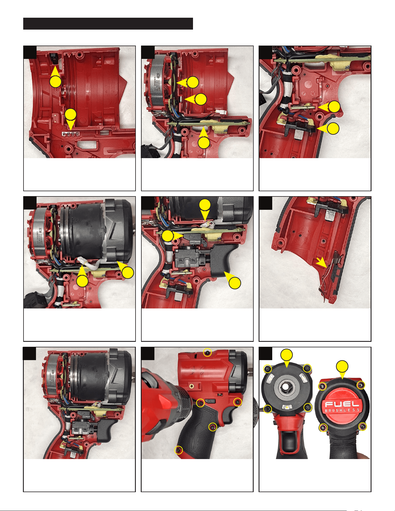
Insert fuel gauge light pipe (A) and mode
select light pipe (B) into the slots on the
handle.
Place HV terminal wire clip on housing
ridge (A). Insert electronics assembly
into slots for stator (B) and PCBA board
(C) into housing cavity as shown.
Route wires and place battery terminal
(A) and hall board (B) into slots as
shown, being sure that they are firmly
and squarely seated in the cavities.
Place gearcase assembly into proper
location (A). Attach white wire
connectors together (B).
Be sure to tuck wire connectors into wire
channel (A). Place trigger switch (B) and
shuttle (C) into housing cavities.
Insert leaf spring (fig.43) into bottom left
handle half slots as shown.
(A) Secure gearcase assembly to
housing with four T-20 screws (fig.1).
(B) Install rotor/back cap assembly and
secure with four T-10 screws (fig.41).
Check that all elements of electronics
assembly are seated properly and that
all wires are pressed completely down
in wire traps and channels.
Carefully install right housing cover onto
left housing support and secure with five
housing halve T-10 screws (fig.41). Check
functionality of shuttle and on-off switch.
B
B
A
B
B
C
C
A
A
A
B
A
B
A
1 2
3
4
5 6
7 8
9
WIRING/ELECTRONICS ASSEMBLY INSTRUCTIONS