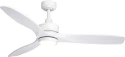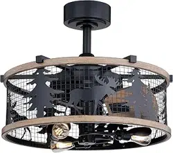
Model No.: F0103
ORIGINAL VAXCEL CEILING FAN LIMITED LIFETIME WARRANTY*
*for full limited lifetime warranty details please see final page of these instructions.
Safety Instructions
READ ALL SAFETY INFORMATION AND INSTALLATION INSTRUCTIONS BEFORE YOU BEGIN TO
INSTALL THE FAN AND SAVE INSTRUCTIONS.
•
All set screws of the fan must be checked and retightened where necessary before installation.
•
To reduce the risk of personal injury, do not bend the blade brackets when installing the brackets,
balancing the blades or cleaning the fan. Do not insert foreign objects between rotating fan blades.
•
Before changing the fan direction, turn off the fan and wait for the fan blades to stop completely.
•
The safeguards provided by these safety instructions and by the separate installation instructions
are not meant to cover all possible conditions and situations that may occur. It must be understood
that common sense, caution and care are factors which can not be built into this product. These
factors must be supplied by the person(s) installing, caring for and operating the fan.
WARNING
• TO AVOID RISK OF ELECTRIC SHOCK, BE SURE TO SHUT OFF POWER AT THE MAIN
FUSE OR CIRCUIT BREAKER BOX BEFORE INSTALLING OR SERVICING THIS
FIXTURE. TURNING OFF THE ELECTRICAL POWER BY USING THE LIGHT SWITCH
IS NOT SUFFICIENT TO PREVENT ELECTRICAL SHOCK.
•
TO REDUCE THE RISK OF INJURY, INSTALL THE FAN SO THAT THE BLADES ARE
AT LEAST 7 FEET (2.1 METERS) ABOVE THE FLOOR AND AT LEAST 18 INCHES
(0.5 METERS) FROM THE TIP OF THE BLADES TO THE WALL.
•
TO REDUCE THE RISK OF FIRE, ELECTRIC SHOCK, OR PERSONAL INJURY, MOUNT
TO OUTLET BOX MARKED "ACCEPTABLE FOR FAN SUPPORT" AND USE MOUNTING
SCREWS PROVIDED WITH THE OUTLET BOX.
•
THE INSTALLATION HAS TO BE IN ACCORDANCE WITH THE NATIONAL ELECTRICAL
CODE, ANSI/NFPA 70-1999 AND LOCAL CODES. IF YOU ARE UNFAMILIAR WITH THE
METHODS OF INSTALLING ELECTRICAL WIRING, SEEK THE SERVICES OF A
QUALIFIED LICENSED ELECTRICIAN.
•
CETL LISTED FOR DAMP LOCATIONS; FOR USE IN COVERED PORCHES PATIOS
OR SUNROOMS WHERE RAIN OR WATER WILL NOT REACH THE CEILING FAN.
PAGE: 1 / 12
231013
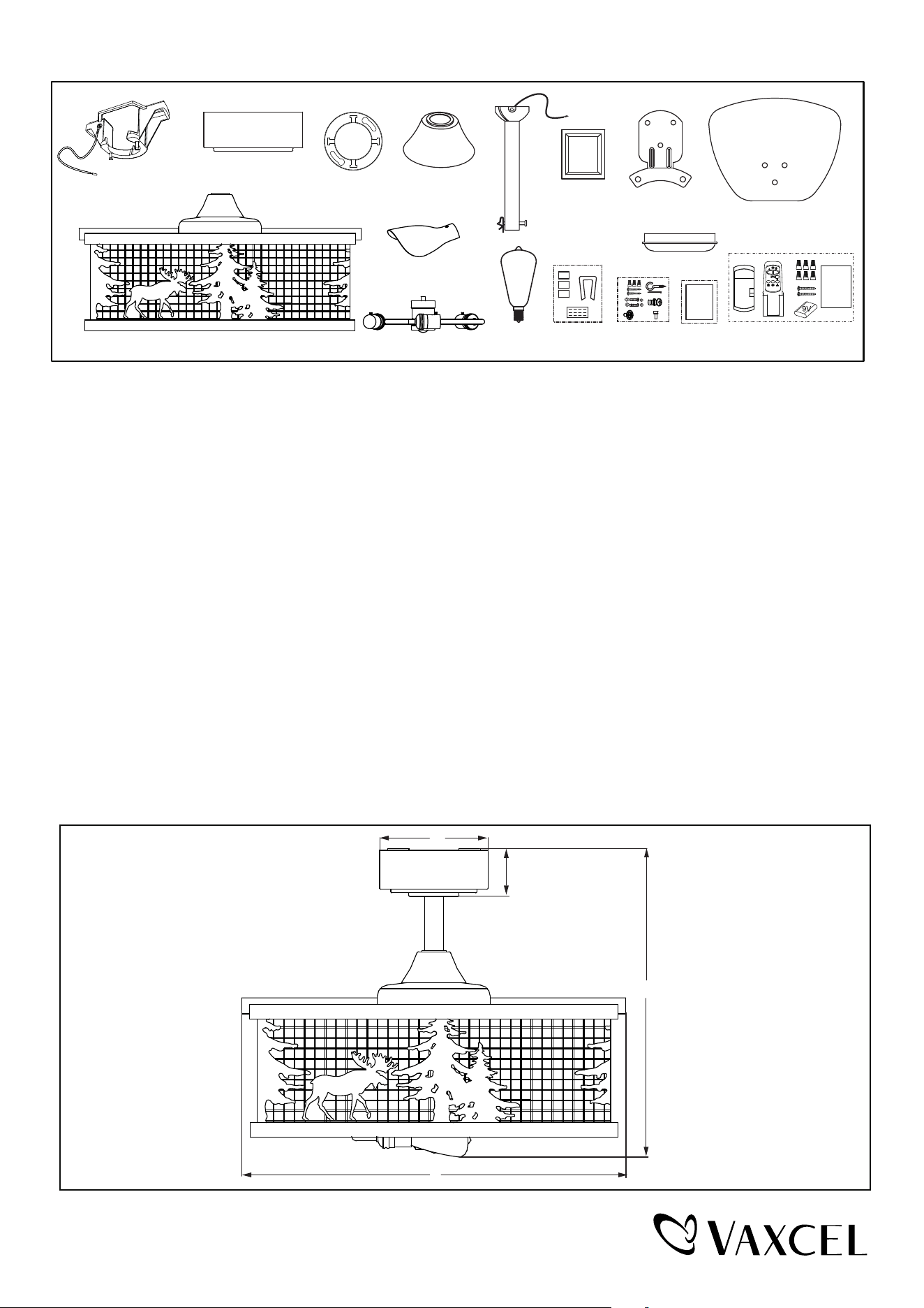
Unpack your fan and check the contents. You should have the following items.
1.) Hanger Bracket
2.) Canopy
3.) Canopy Cover (Comes in a Separate Bag)
4.) Downrod Stand Cover
5.) Downrod Set (Includes Hanger Ball, 6˝ Downrod, Hanger Pin & Lock Pin)
6.) Decorative Plate (3 PCS)
7.) Blade Bracket (3 PCS)
8.) Fan Blade (3 PCS)
9.) Fan Motor Assembly
10.) LED Bulb Cover (3 PCS)
thgiL naF ).11
12.) 5W E12 (C) Base ST15 Type LED Bulb (3PCS)
13.) Switch Box Cover
14.) Blade Balancing Kit
15.) Assembly Kit
16.) Installation Instructions
17.) Remote Control Set (Includes Receiver & Transmitter & Wire Connectors & Battery
& Screws & Remote Control Instructions)
Package Contents:
Dimension Reference (Installed with 6˝ Downrod):
A. 17˝ B. 21˝ C. 2-1/2˝ D. 6˝
1
2
3
4
5
6
7
8
10
9
11
12
13
14 15 16 17
Installation
Instructions
D
C
A
B
X
1
0
Remote
Control
Instructions
PAGE: 2 / 12
231013
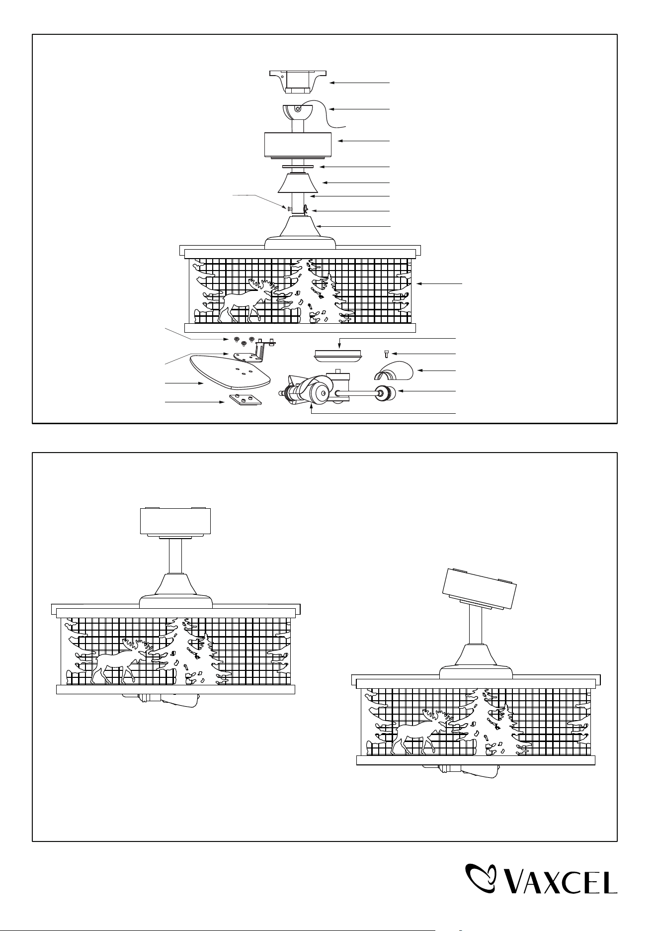
Downrod Mount
Sloped Ceiling Mount (Up to 23 degrees)
Dual Mount Drawing
Exploded View Detail
Hanger Bracket
Canopy
Canopy Cover
Downrod Stand Cover
Downrod
Hanger Ball
Collar
Lock Pin
Fan Motor Assembly
Hanger Pin
Blade Bracket
Screw Set
Blade
Decorative Plate
LED Bulb Cover
Decorative Screw
Fan Light
Switch Box Cover
LED Bulb
PAGE: 3 / 12
231013
Installation Steps :
INSTALLATION INSTRUCTIONS
IMPORTANT:
BEFORE YOU BEGIN INSTALLING THE FAN, CAREFULLY READ ALL INFORMATION IN THE SEPARATE
SHEET "SAFETY INSTRUCTIONS" AS WELL AS THE FOLLOWING "INSTALLATION INSTRUCTIONS". IF IN
DOUBT, CONSULT A QUALIFIED ELECTRICIAN.
SAVE ALL INSTRUCTIONS.
NOTE: The fan weight is 15.21 lbs (6.9 kg). Be sure the outlet box you are using is securely attached to the building
structure and can support the full weight of the fan. Failure to do so can result in serious injury.
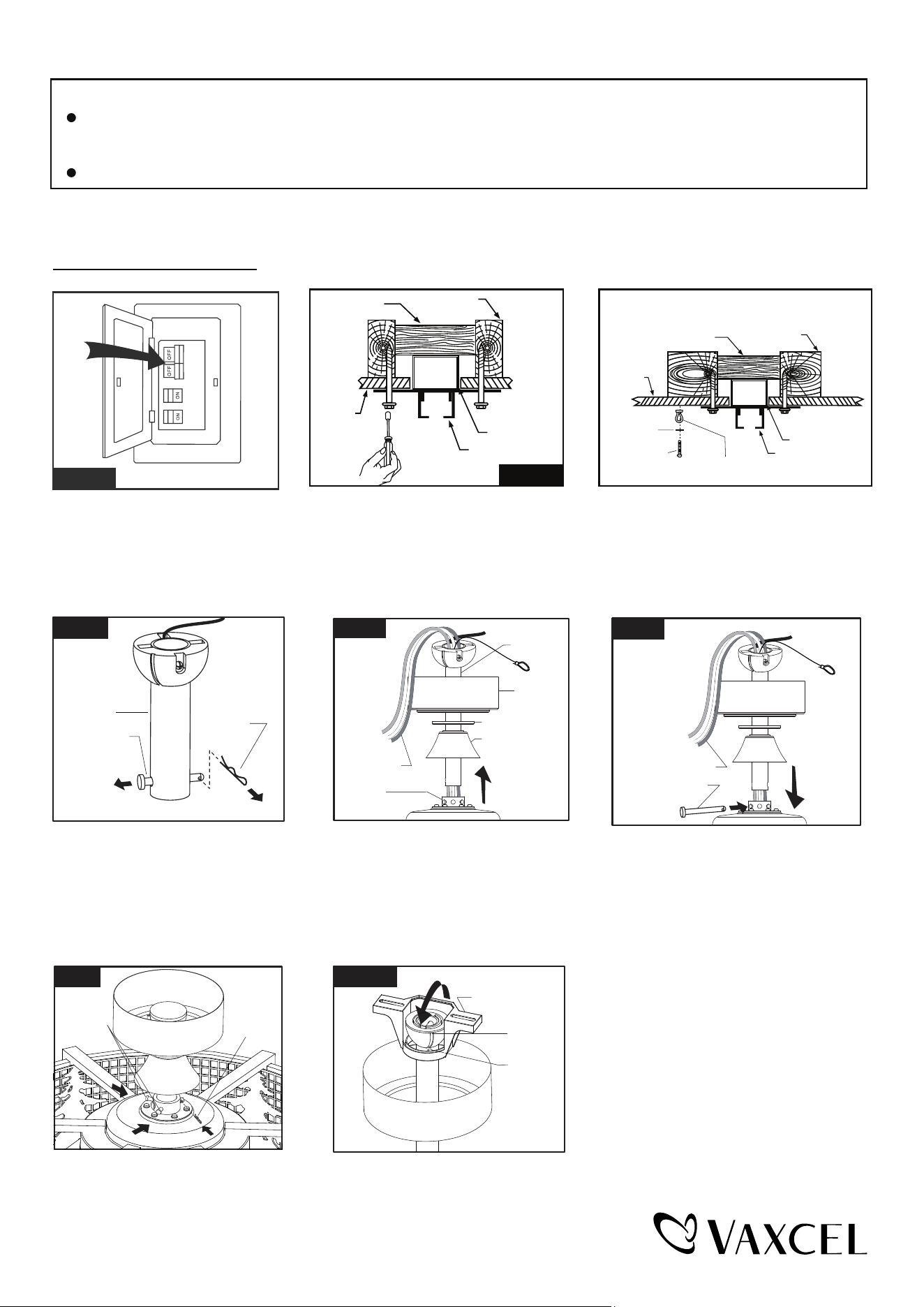
Remove the lock pin from hanger
pin and remove the hanger pin
from the downrod.
Hanger Pin
Downrod
Lock Pin
Fig.3
Hang fan on hanger bracket, and rotate
the downrod until the chip on the hanger
bracket snaps into the slot on the hanger
ball.
Note: For sloped ceiling installation,
make sure the slot of hanger ball
and the chip of hanger bracket are
toward the floor.
Slot
Chip
Hanger Bracket
Fig.7
Fig.5
Hanger Pin
Motor Wires
Fig.1
Turn OFF the electric circuit at the
main fuse or circuit breaker box.
Fig.4
Motor Wires
Collar
Downrod
Canopy
Canopy Cover
Downrod Stand
Cover
Collar
Screws
Fig.6
Lock Pin
Tighten the hanger bracket to the outlet box with two mounting screws.(Make sure
the outlet box is securely installed so that it will be able to support at least the
fan weight.) Attach the safety cable hook to the ceiling with the drywall screw and
washer, and make sure the safety cable hook is covered by the fan canopy.
WARNING: MOUNT ONLY TO AN OUTLET BOX MARKED "ACCEPTABLE FOR
FAN SUPPORT"!
Washer
Safety Cable Hook
Drywall Screw
Ceiling
Hanger Bracket
Ceiling Joist
Wood Member
(2" x 4" Approx.)
Junction Box
Fig.5.Fig.2
Ceiling
Hanger Bracket
Ceiling Joist
Wood Member
(2" x 4" Approx.)
Junction Box
Slide canopy, canopy cover (Making
sure the smooth side of canopy
cover is facing downward.) and
downrod stand cover onto downrod,
as shown; then thread motor wires
through downrod.
Loosen the collar screws out part way.
Insert the downrod into the collar.
Slide hanger pin through holes of
collar and downrod.
Tighten the two collar screws.
Slide lock pin into hanger pin until
it locks into position.
PAGE: 4 / 12
231013
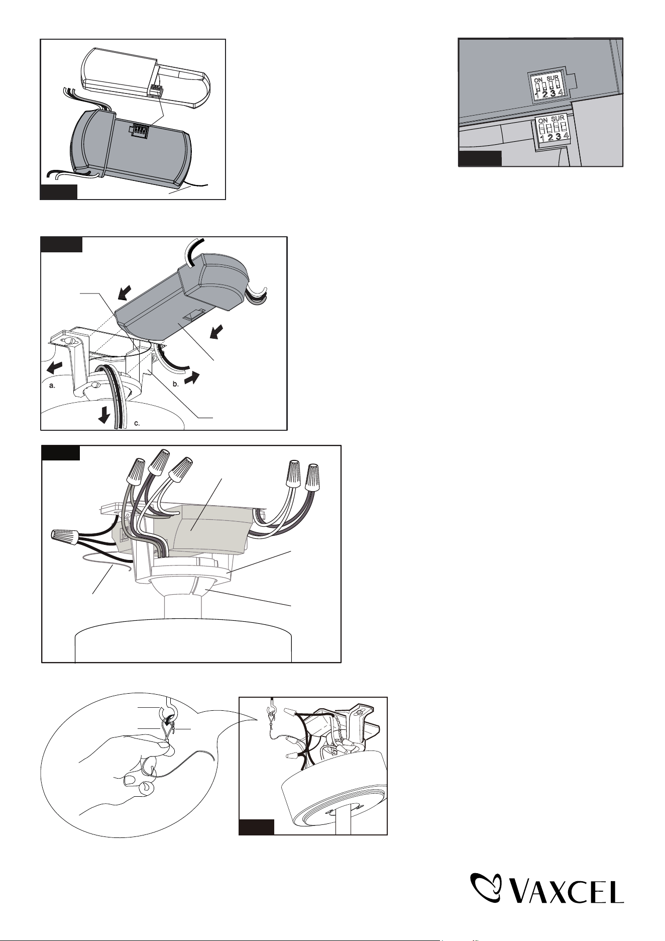
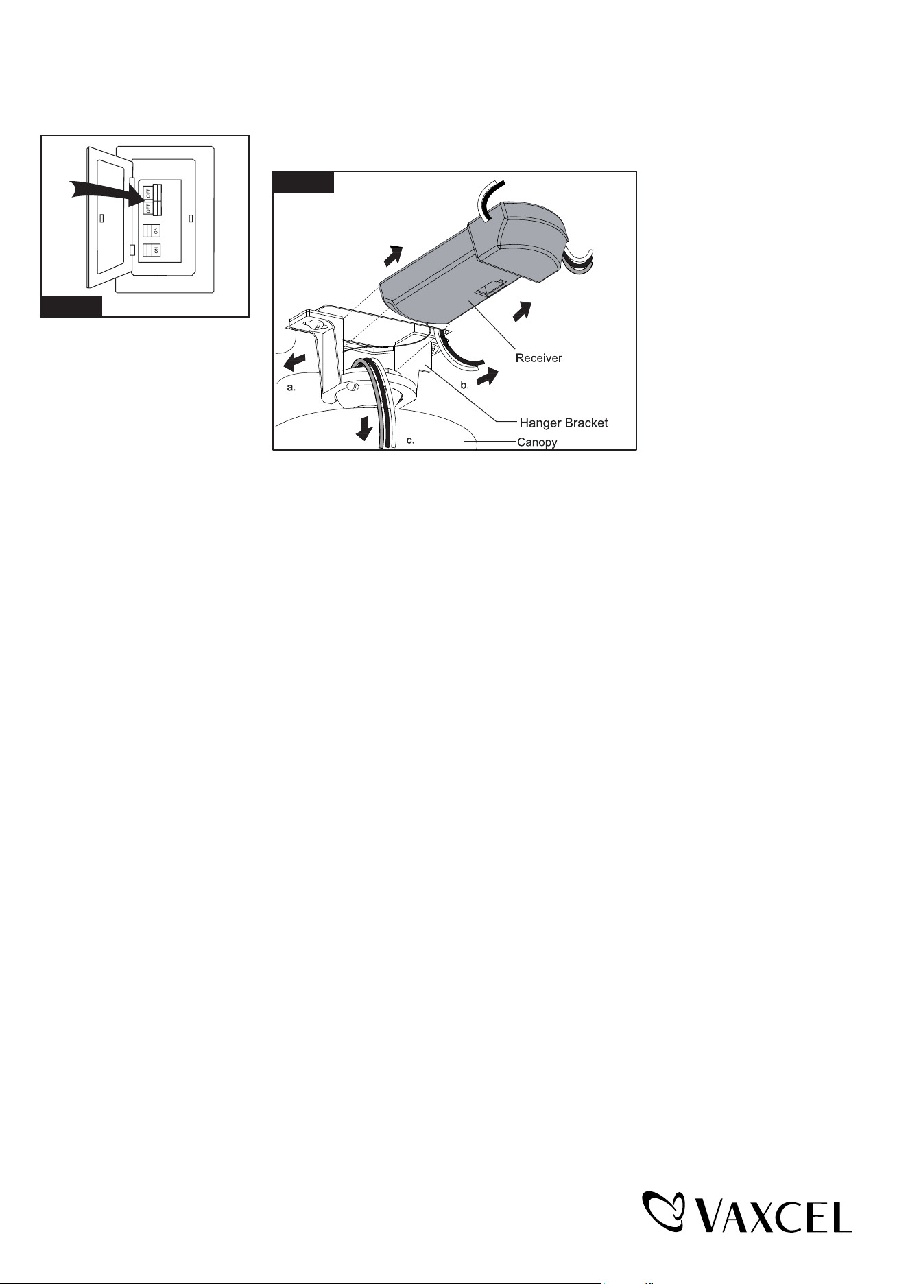
Move Ground Wires (a), Outlet Box wires (b), and
Motor Wires (c) away from the center of the Hanger
Bracket. Then slide Receiver through Hanger
Bracket as shown, Antenna end first, until it is
placed in the center. Finally, cut Motor Wires (c)
to length needed for connections.
Code example:
1-ON 2-OFF 3-ON 4-OFF on both
SUR Switches.
Note: If you have two ceiling fans
with 2 remote control units, set 2
different codes for each set of
transmitter / receivers.
Make wire connections:
1) The Motor white wire to the white "To Motor N" wire from
Receiver with a wire connector.
2) The Motor black wire to the black "To Motor L" wire from
Receiver with a wire connector.
3) The Motor blue wire to the blue "For Light" wire from
Receiver with a wire connector.
4) The white wire from Outlet Box to the white "AC in N" wire
from Receiver with a wire connector.
5) The black (hot) wire from Outlet Box to the black "AC in L" wire
from Receiver with a wire connector.
6) The ground wire from Outlet Box to the green ground wire
from the Hanger Ball and the green ground wire from the
Hanger Bracket with a wire connector.
Make sure all of wire connectors are connected firmly.
*** Tuck all wire connectors and wires carefully up into the
Outlet Box.
Fig.8
Both the transmitter and receiver have a 4-key
unit code on each SUR Switch (Fig.8) and by
default, all keys are pre-set to the "off" position.
This means that the transmitter and receiver are
already paired together. However, if you have
multiple fans and remote controls and want to
avoid interference between them, you can "pair"
other transmitters and receivers together by
adjusting the SUR switches, so the same
numbered keys are in the "ON" position
on both (Fig.8a).
Note: The ceiling fan may work abnormally
if there is interference from other remote
controls.
Antenna
SUR Switch
Transmitter
Receiver
SUR
ON
ON SUR
Fig.9
Hanger Bracket
Receiver
Antenna
Fig.10
Hanger
Bracket
Hanger
Ball
Receiver
1.
4.
5.
6.
.3 .2
Antenna:
DO NOT CUT
OR SPLICE
Hang the safety cable into the safety cable hook,
tighten the safety cable to the safety cable hook
by using the zip-tie.
Fig.11
Safety Cable Hook
Safety Cable
Zip-tie
Fig.8a
PAGE: 5 / 12
231013
Slide the canopy up to ceiling and over
the two canopy screws on hanger
bracket. Rotate canopy clockwise, next,
while holding the canopy with one hand,
slide the canopy cover over the screws
and rotate clockwise until tight.
Note: Adjust the canopy screws as
necessary until the canopy and
canopy cover are snug.
Fig.12
Canopy Screw
Hanger Bracket
Canopy
Canopy Cover
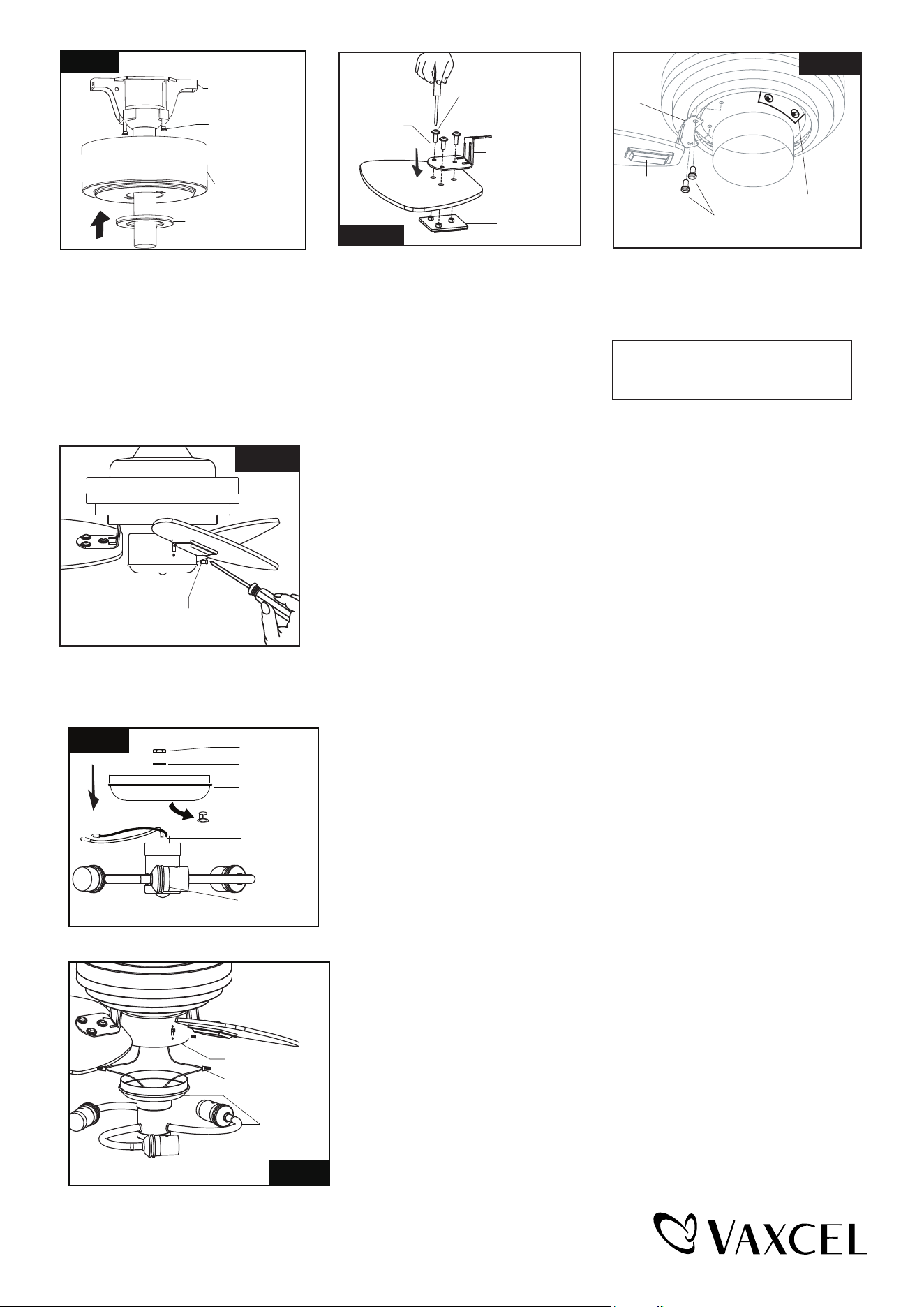
NOTE: Before installing blade
brackets to the motor, please
remove the plastic inserts.
Remove the motor screws from fan motor
assembly.
Secure blade brackets to the motor with
motor screws.
Fig.13
Blade Screw
Washer
Blade Bracket
Blade
Decorative
Plate
Fig.14
Motor Screw
Blade Bracket
Decorative
Plate
Plastic Insert
Thread the blade screws through the
blade bracket, and blade into the
decorative plate. Tighten all blade
screws securely. Repeat to other
blades.
Fan Light Installation:
Hex Nut
Washer
Switch Box
Cover
Plug
Fan Light
Nipple
Fig.16
Remove the plug from the switch box cover. Attach the fan light to the
switch box cover by threading the fan light wires (black and white) and
rotate nipple through the hole of switch box cover and then screw them
onto the switch box cover with nut & lock washer. Be sure it is tight enough
to prevent light kit from vibrating loose.
Assembly without fan light
Make sure the lead wire of fan light
in switch box is sealed with a wire
connector exactly. Secure the switch
box cover into switch box with the
switch box screws.
Switch Box
Screw
Fig.15
Make wire connection:
-- connect the blue wire from the switch box to black wire from the fan light with
wire connector.
-- connect the white wire from the switch box to white wire from the fan light with
wire connector.
Fan Light
Wire Connector
Fig.17
Switch Box
PAGE: 6 / 12
231013
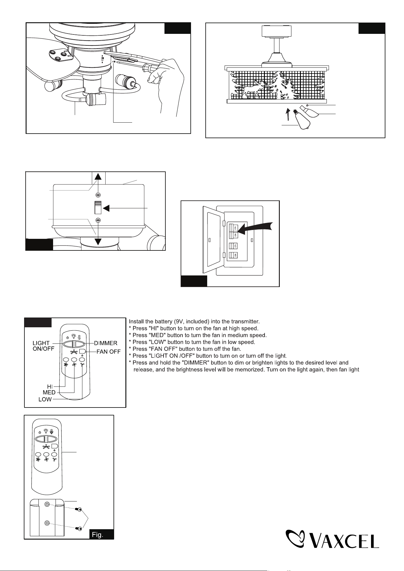
Fig.19
3-5W E12 Base ST15
Type LED Bulbs (included)
E12 Base ST15 Type
LED bulbs Max.60W
LED Bulb Cover
Decorative Screw
Install LED bulbs (included). See relamping label at socket
area or packaging for maximum allowed wattage.
Optional: To avoid reflection of light, remove the decorative
screws from the lampholder, gently screw LED bulb covers
on the lampholder with decorative screws.
The slide switch on switch box sets direction
of fan rotation. Select the desired direction of
fan rotation.
Push the slide switch down for " Forward" and
up for "Reverse”.
Note: Wait for fan to stop before reversing the
direction of blade rotation.
Turn ON the electric circuit at the
main fuse or circuit breaker box.
Fig.21
will be restored to the brightness-level at which was dimmed last time.
Fig.22
Note:
1. This remote controller has a memory function setting. The fan will operate at the
same speed and the fan light will stay at the same brightness-level as the last time
the power supply was turned off.
2. Compatible Wall Switches: Lutron SKU# S2-LFSQH-WH / Hunter SKU# 27183.
3. Compatible with E12 (C) base dimmable LED bulb: Feit Electric SKU# CTC40-827-LED-6.
Fig.18
Set Screw
Fan Light
Carefully put the wires into the switch box, then attach
the fan light into the switch box with the switch box
screws.
Slide
Switch
Reverse
Switch Box
Forward
Fig.20
Transmitter
Wall Bracket
Screw
23
Install the transmitter wall bracket on the wall with two screws and place transmitter in it carefully.
PAGE: 7 / 12
231013
Install Without Remote Controller
Fig.24
Turn OFF the electric circuit at the main fuse or circuit breaker box. (See Fig.24)
Unscrew the canopy. Remove
the wire connectors from the
fan to ceiling wire connection.
The receiver should be removed
from the hanger bracket.
(See Fig.25)
Fig.25
Note: Remote controller can not be used along with a solid-state speed control at the same time.
PAGE: 8 / 12
231013
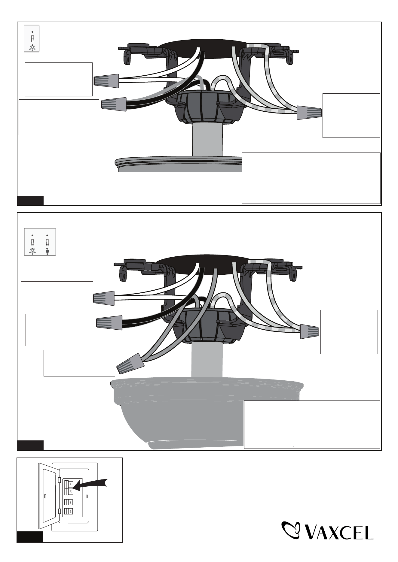
Fig.26
Connect the white (neutral)
wire from motor to the white
(neutral) wire from the
outlet box with a wire
connector.
Connect the black (hot) wire
(This is for fan control) and blue
wire (This is for light control) from
motor to the black (hot) wire from
outlet box with a wire connector.
Bla
Black
ck
Blue
Green
White
White
Grounding
Green
*** After making the wire connections, the wires should
be spread apart. The white (neutral) conductor and
green (grounding) conductor on one side and the
black (hot) conductor and blue (light) conductor on
the other side of the outlet box.
*** The wire connection points should be turned upward
and pushed carefully up into outlet box.
Connect three
ground wires (Green
or bare copper) coming
from outlet box,
downrod and hanging
bracket with a wire
connector.
For a single switch
Follow these steps:
Connect three
ground wires (Green
or bare copper) coming
from outlet box,
downrod and hanging
bracket with a wire
connector.
Connect the black (hot) wire
from motor (This is for fan
control) to the black (hot)
wire from outlet box with a
wire connector.
Green
Black
Blue
Green
White
Black
Blue
(light)
White
Grounding
Connect the white (neutral)
wire from motor to the white
(neutral) wire from outlet box
with a wire connector.
Connect the blue wire (This
is for light control) from motor
to the blue wire from outlet
box with a wire connector.
*** The wire connection points should be turned
upward and pushed carefully up into outlet box.
Fig.28
Turn ON the electric circuit at the main fuse or circuit breaker box.
For dual switches
Follow these steps:
*** After making the wire connections, the wires should
be spread apart. The white (neutral) conductor and
green (grounding) conductor on one side and the
black (hot) conductor and blue (light) conductor on
the other side of the outlet box.
Fig.27
PAGE: 9 / 12
231013

Troubleshooting Guide
If you have difficulty operating your new ceiling fan, it may be the result of incorrect assembly, installation
or wiring. In some cases, these installation errors may be mistaken for defects. If you experience any
faults, please check this Troubleshooting Guide. If a problem cannot be remedied or you are
experiencing difficulty in installation, please call our Customer Service Department (1-800-482-9235).
PROBLEM
1. If fan does not start:
2. If fan sounds noisy:
3. If fan wobbles:
4. If light does not work:
1. Make sure all screws in motor housing are snug. (not too tight)
2. Make sure the screws which attach the fan blade bracket to the motor are tight.
3. Make sure wire connectors in switch housing are not rattling against each
other or against the interior wall of the switch housing.
CAUTION: Make sure main power is turned off before accessing switch
housing.
4. If using an optional ceiling fan light kit, check to be sure the screws securing
the glassware are finger tight. Check to be sure light bulb is tight in socket and
not touching glass shade(s). If vibration persists from glass, remove glass and
install a 1/4 in. wide rubber band on glass neck to act as an insulator. Replace
glass and tighten screws against rubber band.
5. Some fan motors are sensitive to signals from Solid State variable speed
controls. DO NOT USE a Solid State variable speed control.
6. Allow "break-in" period of 24 hours. Most noises associated with a new fan will
disappear after this period.
All blades are weighed and grouped by weight. Natural woods vary in density
which could cause the fan to wobble even though all blades are weight-matched.
The following procedures should eliminate most of the wobble. Check for wobble
after each step.
1. Check that all blades are screwed firmly into blade brackets.
2. Check that all blade brackets are tightened securely to motor.
3. Make sure that canopy and mounting bracket are tightened securely to ceiling
junction box and junction box is mounted firmly to ceiling joist.
4. Most fan wobble problems are caused when blades are not equally level. To
check the blade levels, select a point on the ceiling above the tip of any blade.
Measure the distance from the ceiling to the blade tip, to an accuracy of 1/8
inch. Rotate the blades until the next blade is in the measuring position. Repeat
measurement for each blade. If all blade levels are not equal, you can adjust
blade levels by the following procedure. To adjust a blade tip down, insert a
washer (not supplied) between the blade and blade bracket at the screw
closest to the motor. To adjust a blade tip up, insert washer (not supplied)
between the blade and blade bracket at the two screws farthest from the motor.
5. If blade wobble is still noticeable, interchanging two adjacent (side by side)
blades can redistribute the weight and possibly result in smoother operation.
1. Check blue wire from fan to make sure it is connected to hot wire from house.
2. Check for loose or disconnected wires in fan switch housing.
3. Check for loose or disconnected wires in light kit.
4. Check for faulty light bulbs.
CAUTION: Make sure main power is turned off before accessing switch housing.
SUGGESTED REMEDY
1. Check main and branch circuit fuses or circuit breakers.
2. Make sure forward/reverse switch is firmly in left or right position. Fan will not
operate when switch is in the middle.
3. Make sure that the wall control is turned "ON".
4. Check line wire connections to fan and switch wire connections in switch
housing.
CAUTION: Make sure main power is turned off.
PAGE: 10 / 12
231013
DYNAMIC BLADE BALANCING KIT
PREFACE
Your ceiling fan may sometimes have wobbling problems when operating due to irregularity in the
blades or the blade brackets. Improper assembly in the mounting system may cause some additional
problems. This balancing kit can be used to fix wobbling problems.
DYNAMIC BLADE BALANCING KIT FOR CEILING FANS
1. Make sure that all blades are firmly screwed into the blade brackets.
2. Make sure that all blade brackets are firmly secured to the motor housing.
3. By looking up at the fan from below, check and be certain that none of the blade brackets are bent
and that none of the blades are out of position.
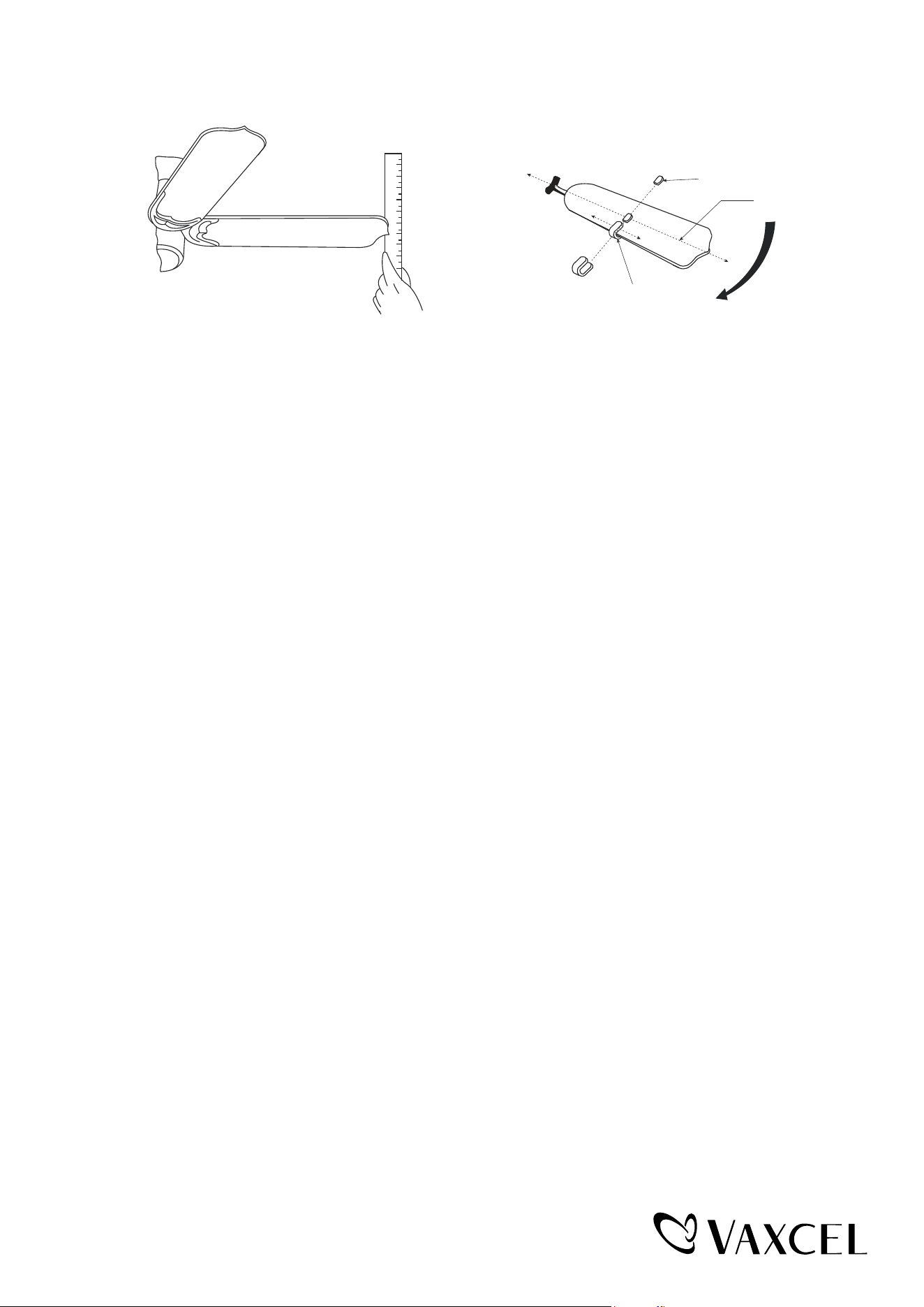
4. Use a yardstick to check the blade tracking. Put the yardstick up against the ceiling vertically and
against the outside leading edge of a blade. Note the distance of the edge of blade to the ceiling.
Carefully turn the blades slowly by hand to check the remaining blades. All distances should be
the same.
Operate the fan ten minutes. After following all the steps and if the wobbling problem is not solved, a
dynamic balancing needs to be done with balancing kit. Follow the procedure listed below:
● Turn the fan off. Select one blade and place the plastic clip on it, with the plastic clip located
halfway between the blade bracket and the blade tip on the edge of the blade.
Caution: The plastic clip should be placed on the windward edge of the blade for fear of
clip flying off.
● Turn the fan on (set the speed that causes the wobble most). Observe if the wobble is better or
worse. Turn the fan off and move the clip to the next blade. Do the same for all blades and note
on which blade the clip reduces the wobble most. Place the clip on the blade which showed the
most improvement. Move the clip inward and outward on this blade and operte the fan to find
the position where the clip gives the most improvement.
Caution: Stay clear of the blades. If the clip, for any reason, is not secure, injury could result.
● Once the exact position is determined, place a weight on the top of the blade, on its centerline and
as close as possible to the clip. Peel the paper off of the back of the weight and press firmly to
ensure that it is securely attached to the blade. Remove the clip.
Caution: Clean the surface of fan blade before placing the balancing weight so that the
balancing weight will be firmly attached to it.
BALANCING WEIGHT
MEASURING
POINT
YARDSTICK
PLASTIC CLIP
CENTERLINE
COUNTER-
CLOCKWISE
1
2
3
4
5
6
7
8
9
PAGE: 11 / 12
231013

PAGE: 12 / 12
231013
The limited lifetime warranty covers this fan, for residential use by the original purchaser, against defects
in material or workmanship as follows:
If your fan motor fails at any time during the lifetime of the original purchaser due to defects in material or
workmanship, we will provide a replacement part free of charge.
If your fan motor fails at any time within one year after the original date of sale to the original purchaser
due to defects in material or workmanship, we will provide labor to repair the defect, with the exception
of take down/reinstallation, free of charge. The original purchaser will be responsible for all labor costs
after this one year period.
If no replacement parts are provided for any part of your fan motor that fails at any time during your
lifetime due to defects in material or workmanship, we will refund the original purchase price of your fan.
If your fan includes any integrated LED modules, the LED functionality is covered by a 5-year warranty.
If your fan blades, or any accessory, except glass globes and light bulbs, fails at any time within one year
after the original date of purchase due to a defect in material and workmanship, we will repair or replace
the defective blades, switch, or accessory free of charge, with the exception of take down/reinstallation
services.
If the original purchaser ceases to own the fan, this warranty and any implied warranty, including but not
limited to any implied warranty of merchantability or fitness for a particular purpose, become void. This
warranty and any implied warranty, including but not limited to any implied warranty of merchantability or
fitness for a particular purpose, does not cover glass globes, light bulbs, or finish on any metal portions of
the fan.
This warranty is in lieu of express warranties. The duration of any implied warranty of merchantability or
fitness for a particular purpose, with respect to any fan motor, blades, switch, or accessories, is expressly
limited to the period of the express warranty set forth above for such motor, LED modules, blades, switch,
or accessories.
This warranty excludes defects, malfunctions, or failures of any fan that are caused by repairs by persons
not authorized by us, use of parts or accessories not authorized by us, mishandling, improper installation,
modifications or damage to the fan while in your possession, or unreasonable use, including failure to
provide necessary maintenance. This warranty does not include the failure of products from extreme acts
of nature; environmental conditions not suited for the products intended use; operation in temperatures
outside of the range specified in the instruction manual; usage with improper power supply, power surges
or dips. For coastal locations, some corrosion is considered normal for the environment.
In no event shall VAXCEL be liable for consequential or incidental damages.
Some states do not allow the exclusion or limitation of consequential or incidental damages, in which case
the above limitation or exclusion may not apply. This warranty gives you specific legal rights and you may
also have other rights which vary from state to state.
Vaxcel reserves the right to repair, replace or issue a credit for any properly installed product, provided
it is returned per RMA instruction. This warranty is limited to the cost of the product only and does not
extend to transportation, installation or replacement costs.
ORIGINAL VAXCEL CEILING FAN LIMITED LIFETIME WARRANTY*
How can warranty service be obtained for your ceiling fan?
1-800-482-9235