
HIGH PERFORMANCE WATER FILTRATION SOLUTIONS
Water_Filtration_Cover_03_23_20.indd 2Water_Filtration_Cover_03_23_20.indd 2 3/24/20 3:11 PM3/24/20 3:11 PM

GENERAL
BUNN High Performance Water Filtration Solu-
tions are specically designed to operate as a
universal ltration system offering multiple l-
tration packages in order to provide the best
water quality across several food service appli-
cations. Built upon the ability to come in sev-
eral head / ltration package congurations,
it can accommodate multiple ltration needs,
ow rates and scale prevention options in the
product line.
Options include the reduction of particulates
such as sand, silt, sediment and rust, as well
as chlorine/chloramines with improved taste
and clarity of the water, which preserves the
taste of carbonated and non-carbonated bev-
erages, coffee, tea, and ice. Our scale and cor-
rosion inhibitor packages can be automatically
fed into the recipe water to inhibit the forma-
tion of scale in ice machines, coffee brewers,
steamers and other applications that require
scale control.
Our lters have been tested and certied by
NSF International, which is globally recog-
nized as the premier certication for public
health requirements.
OWNER INFORMATION
TABLE OF CONTENTS
Owner Information ................................ 2
General .............................................. 2
Key Features ...................................... 3
ADDITIONAL Features (WQ MODEL
ONLY)
................................................. 3
Technical Assistance .......................... 3
Important Safety Information ............. 4
Warranty Information ......................... 6
System Specications ............................ 7
General .............................................. 7
Dimensions ........................................ 7
Cartridge Specications & Performance
Data
....................................................... 8
General .............................................. 8
WEQ Models ..................................... 8
WQ Models ........................................ 9
Installation ............................................. 10
Modular Design ................................. 11
System Startup ................................... 12
Maintenance .......................................... 13
Removing A Cartridge ....................... 13
Installing A Cartridge ......................... 13
Filter Integrity Ports ............................... 14
Overview ............................................ 14
Upper Port ......................................... 14
Lower Port .......................................... 14
Troubleshooting .................................... 15
Parts Exploded View .............................. 16
Notes ..................................................... 18
56000.0500 B
7/21 © 2021 Bunn-O-Matic Corporation
Page 2
www.bunn.com
803426

OWNER INFORMATION (CONT.)
KEY FEATURES
This product line was specically engineered
after years of industry research. It offers a pro-
prietary cartridge-to-head interface providing
these rst-in-class features:
• Best-in-class performance/capacity
• Modular design for simple customization
and expandability
• Build-on-the-wall capability helps to reduce
inventory
• Reverse and forward compatibility
• Built-in vent/leak detectors
• Auto-leveling technology ensures perfect
installation each time
• Auto shut-off, pressure relief/rinse valves to
ensure simple and safe installation and
system maintenance
• Up to 8 times more scale control capacity
than many of the leading manufacturers
• Proven scale control performance
• High capacity, low pressure drop system
configuration
ADDITIONAL FEATURES (WQ MODEL ONLY)
• Patented Filter Integrity Port guarantees
there will never be unltered water in your
product
• Select individual lters rated up to 7.5 GPM
and 15 GPM
• Up to 265,000+ gallons Chlorine reduction
per cartridge
• Up to 60,000+ gallons Chloramines reduc-
tion per cartridge
TECHNICAL ASSISTANCE
If you have any problems with the installation
or operation of your water ltration system,
please contact us at (800) 286-6070.
Fill in the information below and have it ready
when calling for assistance. The serial number
can be found on the specication plate located
on the system.
Purchased From:
Date of Purchase:
Model No.:
Serial No.:
Mfg. No.:
To ensure you have the latest revision of the
Operating Manual, Illustrated Parts Cata-
log, Programming Manual, or Service Manu-
al, please visit the Bunn-O-Matic web site at
www.bunn.com. This is absolutely FREE and
the quickest way to obtain the latest catalog
and manual updates. For Technical Service,
contact Bunn-O-Matic Corporation at 1-800-
286-6070.
BUNN-O-MATIC CORPORATION
POST OFFICE BOX 3227
SPRINGFIELD, ILLINOIS 62708-3227
PHONE: (217) 529-6601 FAX: (217) 529-6644
www.bunn.com
56000.0500 B
7/21 © 2021 Bunn-O-Matic Corporation
Page 3
www.bunn.com
803426
OWNER INFORMATION (CONT.)
IMPORTANT SAFETY INFORMATION
Read, understand, and follow all safety information contained in these instructions prior to installa-
tion. Retain these instructions for future reference.
Intended Use:
The High Performance Water Filtration Solutions System is intended for use in ltering potable water
in the foodservice industry and has not been evaluated for other uses. The system must be installed
as specied in these installation instructions.
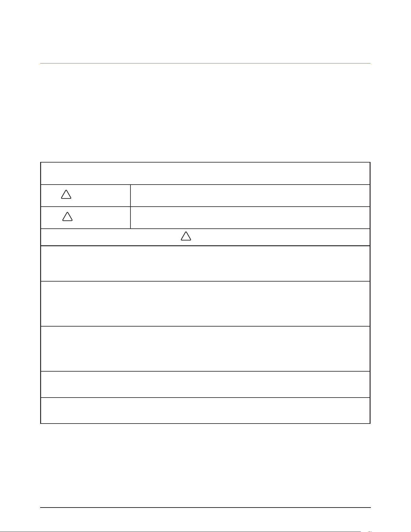
EXPLANATION OF SIGNAL WORD CONSEQUENCES
!
WARNING
Indicates a potentially hazardous situation, which, if not avoided, could
result in death or serious injury and/or property damage.
!
CAUTION
Indicates a potentially hazardous situation, which, if not avoided, may
result in property damage.
!
WARNING
To reduce the risk associated with choking:
• Do not allow children under 3 years of age to have access to small parts during the installation of
this product.
To reduce the risk associated with the ingestion of contaminants:
• Do not use with water that is microbiologically unsafe or of unknown quality without adequate dis-
infection before or after the system. Systems certied for cyst reduction may be used on disinfected
water that may contain lterable cysts. EPA Establishment #10350-MN-007.
To reduce the risk associated with hazardous voltage due to an installer drilling through exist-
ing electric wiring or water pipes in the area of installation:
• Do not install near electric wiring or piping which may be in path of a drilling tool when selecting
the position to mount the lter bracket.
To reduce the risk of physical injury:
• Depressurize system as shown in manual prior to cartridge removal.
To reduce the risk associated with back strain:
• Follow safe lifting procedures.
56000.0500 B
7/21 © 2021 Bunn-O-Matic Corporation
Page 4
www.bunn.com
803426

OWNER INFORMATION (CONT.)
!
CAUTION
To reduce the risk associated with property damage due to water leakage:
• Read and follow Use Instructions before installation and use of this system.
• Installation and Use MUST comply with all state and local plumbing codes.
• Protect from freezing, remove lter cartridge when temperatures are expected to drop below
40°F (4.4°C).
• Do not install on hot water supply lines. The maximum operating water temperature of this lter
system is 100°F (37.8°C).
• Do not install systems in areas where ambient temperatures may go above 110°F (43.3°C).
• Do not install if water pressure exceeds 125 psi (862 kPa). If your water pressure exceeds 80 psi
(552 kPa), you must install a pressure limiting valve. Contact a plumbing professional if you are
uncertain how to check your water pressure.
• Do not install where water hammer conditions may occur. If water hammer conditions exist, you
must install a water hammer arrester. Contact a plumbing professional if you are uncertain how
to check for this condition.
• Where a backow prevention device is installed on a water system, a device for controlling pres-
sure due to thermal expansion must be installed.
• Do not use a torch or other high temperature sources near lter system, cartridges, plastic t-
tings or plastic plumbing.
• On plastic ttings, never use pipe sealant or pipe dope. Use PTFE thread tape only, pipe dope
properties may deteriorate plastic.
• Take care when using pliers or pipe wrenches to tighten plastic ttings, as damage may occur if
overtightening occurs.
• Do not install in direct sunlight or outdoors.
• Do not install near water pipes which will be in path of a drilling tool when selecting the position
to mount the bracket.
• Mount lter in such a position as to prevent it from being struck by other items used in the area
of installation.
• Ensure that the location and fasteners will support the weight of the system when installed.
• Ensure all tubing and ttings are secure and free of leaks.
• The disposable lter cartridge MUST be replaced every 6 months or at the rated capacity or
sooner if a noticeable reduction in ow rate occurs.
IMPORTANT NOTES
• Failure to follow instructions will void warranty.
• Allow a minimum of 2 5/16” (5.87 cm) clear space under lter to facilitate cartridge change.
• Install with the inlet and outlet ports as labeled. Make sure not to reverse connections.
• Some local codes may require the use of a licensed plumber or certied installer when disrupt-
ing a potable water line.
56000.0500 B
7/21 © 2021 Bunn-O-Matic Corporation
Page 5
www.bunn.com
803426

WARRANTY INFORMATION
All BUNN® products are constructed of the nest
materials available and manufactured to high qual-
ity standards. High Performance Water Filtration
Solutions Systems (excluding water lters and water
treatment replacement cartridges) are warranted
to be free from manufacturers’ defects in materials
and workmanship for a period of Five (5) years from
date of purchase, under normal use and service, and
when installed in accordance with BUNN’s recom-
mendations outlined in the ltration systems owner’s
manual. Service Replacement Parts (cartridges, Fil-
ter elements, Feeder elements, etc.) are warranted
to be free from manufacturers’ defects in materials
and workmanship for a period of one (1) year from
the date of purchase or the remainder of the original
warranty, whichever is longer. Discrete Components
(ow restrictors, drain saddles, mounting clips, auto-
matic check vales, etc.) are warranted for a period of
Ninety (90) days from the date of purchase.
All defects or warranty claims must be reported to
BUNN within the applicable warranty period.
1. This warranty does not cover failures due to im-
proper system installation, defects caused by
improper storage or handling prior to placing
the equipment into service. This warranty does
not include overtime charges or work done by
unauthorized service agencies or personnel. This
warranty does not cover normal maintenance,
calibration, or regular adjustments as specied
in operating and maintenance instructions of this
manual, and/or labor involved in moving adja-
cent objects to gain access to the Equipment.
2. BUNN shall not be responsible for any inciden-
tal, special or consequential damages, includ-
ing without limitation, lost prots or the cost of
repairing or replacing other property which is
damaged if this product does not work properly,
other costs resulting from labor charges, delays,
vandalism, negligence, fouling caused by foreign
material, damage from adverse water conditions,
chemical, or any other circumstances over which
the BUNN has no control. This warranty shall be
invalidated by any abuse, misuse, misapplication,
improper installation or improper maintenance
or alteration of the product.
3. This warranty does not cover premature plug-
ging, fouling or scaling of cartridges do to un-
known or aggressive water conditions.
OWNER INFORMATION (CONT.)
4. This warranty excludes pre-lter elements,
batteries, etc.
5. BUNN reserves the right to make changes in de-
sign or add any improvements on any product.
The right is always reserved to modify equip-
ment because of factors beyond our control and
government regulations. Changes to update
equipment do not constitute a warranty charge.
6. If shipment is damaged in transit, the purchaser
should make a claim directly upon the carrier.
Careful inspection should be made of the ship-
ment as soon as it arrives and visible damage
should be noted upon the carrier’s documenta-
tion. Damage should be reported to the carrier.
This damage is not covered under this warranty.
7. RESPONSIBILITY OF THE CONSUMER:
The original purchaser-consumer’s sole respon-
sibility in the instance of a Warranty claim shall
be to notify BUNN of the defect, malfunction, or
other manner in which the terms of this Warranty
are violated. You may secure performance of obli-
gations hereunder by (in writing).
a. Identify the Product involved (by model or se-
rial number or other sufcient description that
will allow BUNN to determine which Product
is defective).
b. Specify where, when and from whom the
Product was purchased.
c. Describe the nature of the defect, malfunc-
tion, or other violation of this Warranty
d. Send such notication together with the de-
fective Product to:
BUNN, Customer Service (217) 529-6601
5020 Ash Grove Dr., Springeld, IL, 62711
THIS WARRANTY GIVES YOU SPECIFIC LEGAL
RIGHTS AND YOU MAY ALSO HAVE OTHER RIGHTS
WHICH VARY FROM STATE TO STATE.
THIS WARRANTY IS EXCLUSIVE AND IS IN LIEU
OF ALL OTHER WARRANTIES, EXPRESSED OR IM-
PLIED, INCLUDING ANY IMPLIED WARRANTY OR
MERCHANTABILITY OR FITNESS FOR A PARTICU-
LAR PURPOSE, EACH OF WHICH IS HEREBY EX-
PRESSLY DISCLAIMED. THE REMEDIES DESCRIBED
ABOVE ARE EXCLUSIVE AND IN NO EVENT SHALL
BUNN BE LIABLE FOR SPECIAL CONSEQUENTIAL
OR INCIDENTAL DAMAGES FOR THE BREACH OR
DELAY IN PERFORMANCE OF THIS WARRANTY.
56000.0500 B
7/21 © 2021 Bunn-O-Matic Corporation
Page 6
www.bunn.com
803426
SYSTEM SPECIFICATIONS
SYSTEM SPECIFICATIONS
GENERAL
The WEQ and WQ models were engineered
after years of industry research. Each model is
-
Minimum Pressure 20 psi (138 kPa)
Maximum Pressure 125 psi (862 kPa)
Minimum Temperature 40°F (4.4°C)
Maximum Temperature 100°F (38°C)
pH Range pH 3 to 10
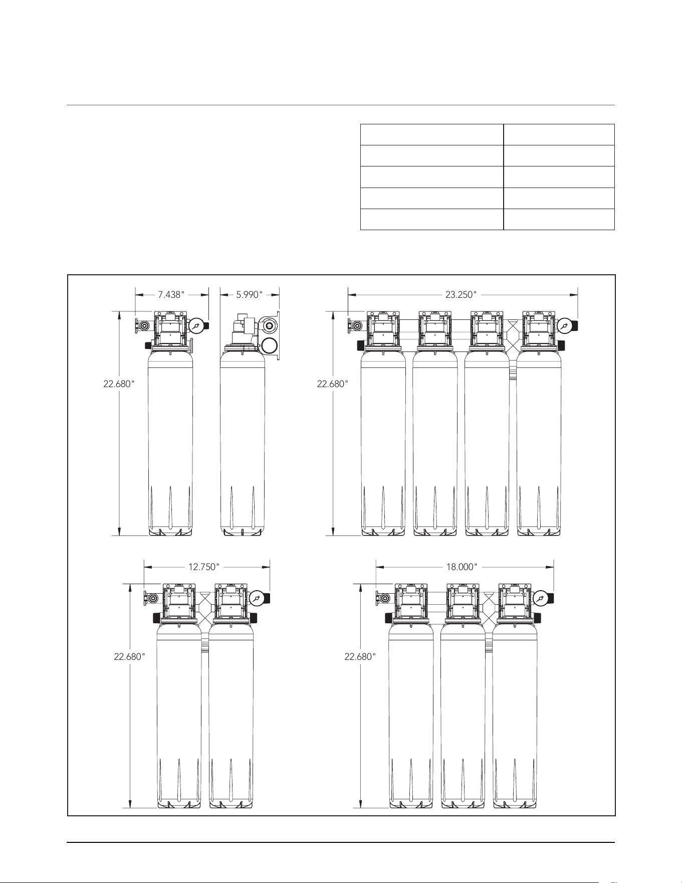
DIMENSIONS
22.680" 22.680"
18.000"12.750"
23.250"
22.680"22.680"
5.990"7.438"
GENERAL
The WEQ and WQ models were engineered
after years of industry research. Each model is
available in different congurations to accom-
modate multiple ltration needs, including
ow rates and scale prevention.
Minimum Pressure 20 psi (138 kPa)
Maximum Pressure 125 psi (862 kPa)
Minimum Temperature 40°F (4.4°C)
Maximum Temperature 100°F (38°C)
pH Range pH 3 to 10
DIMENSIONS
56000.0500 B
7/21 © 2021 Bunn-O-Matic Corporation
Page 7
www.bunn.com
803426
OUTLET PORT
INLET PORT
OUTLET PORT
INLET PORT
CARTRIDGE SPECIFICATIONS & PERFORMANCE DATA
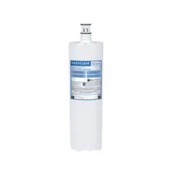
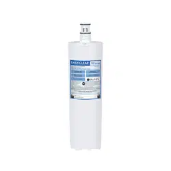
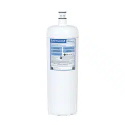
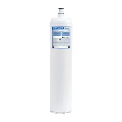
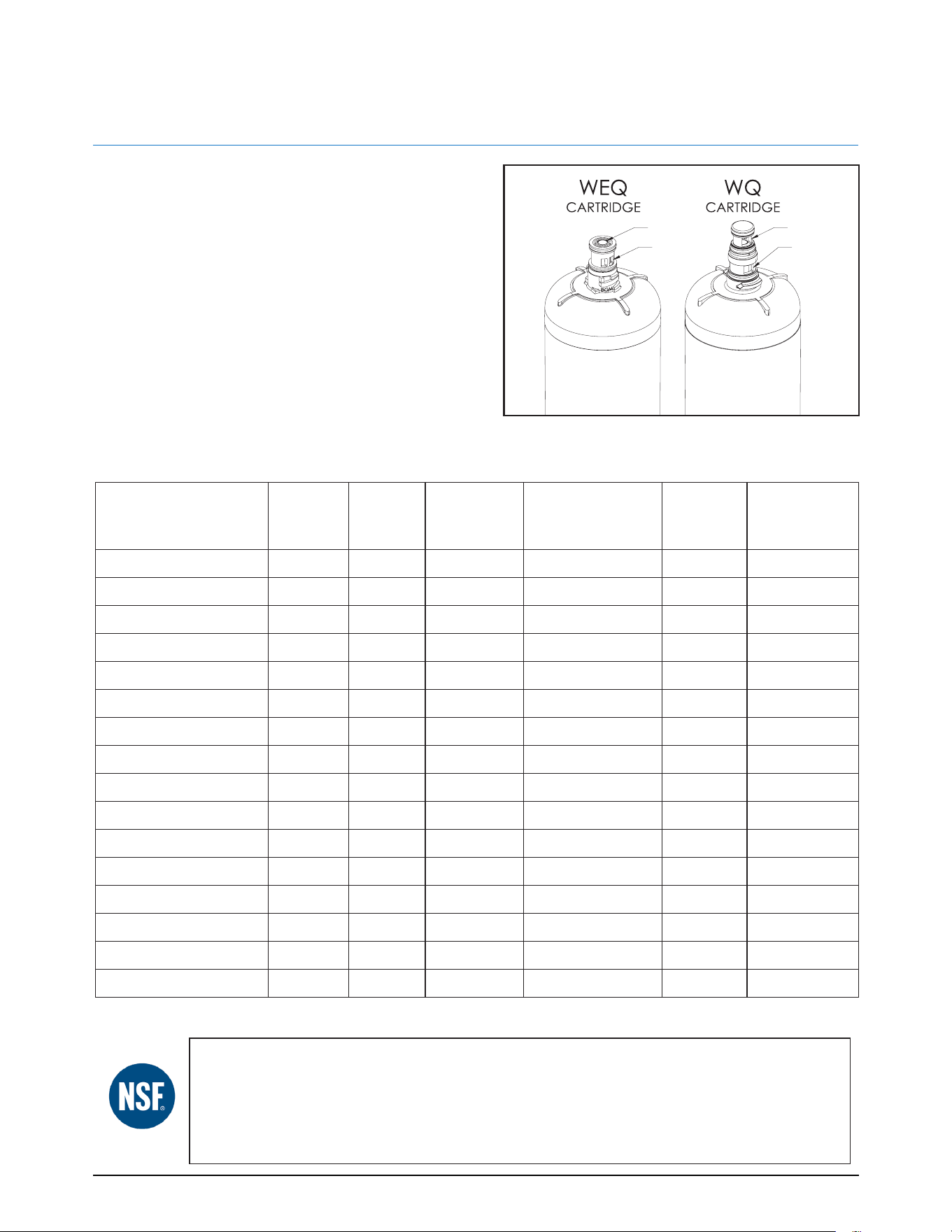
GENERAL
The cartridges for the WEQ and WQ models are
each distinct. WEQ cartridges feature a shorter
cartridge interface design with the outlet port
on the top of the interface and the inlet port on
the body of the interface. WQ cartridges have
a at top with the outlet port and inlet ports on
the body of the cartridge interface (Figure 1).
WEQ MODELS
Model No.
Micron
Rating
Flow
Rate
(gpm)
Capacity Std. 42 Std. 53
Scale
Reduction
WEQ-18(2).2C 0.2 2.10 18,000 Chloramine Cyst No
WEQ-10(1.5)5 5.0 1.50 10,000 Chlorine No No
WEQ-10(1.5)5L 5.0 1.50 10,000 Chlorine No Yes
WEQ-10.3(1.67)5 5.0 1.67 10,300 Chlorine No No
WEQ-10.3(1.67)5L 5.0 1.67 10,300 Chlorine No Yes
WEQ-14(1.67)5L 5.0 1.67 14,000 Chlorine No Yes
WEQ-14(2)5L 5.0 2.10 14,000 Chlorine No Yes
WEQ-20(1.67).5 0.5 1.67 20,000 Chlorine No No
WEQ-25(2).2 0.2 2.10 25,000 Chlorine Cyst No
WEQ-25(2).2L 0.2 2.10 25,000 Chlorine Cyst Yes
WEQ-35(3).2L 0.2 3.00 35,000 Chlorine Cyst Yes
WEQ-54(5).2 0.2 5.00 54,000 Chlorine Cyst No
WEQ-54(5).2L 0.2 5.00 54,000 Chlorine Cyst Yes
WEQ-SCALE-PRO.X N/A 10.00 6 Months Mat'l/Structural No Yes
WEQ-SFTN1500(1)10 10 1.00 1500 Gr N/A No Yes
WEQ-SFTN3500(1)10 10 1.00 3500 Gr N/A No Yes
FIGURE 1. CARTRIDGE PORTS/INTERFACES
This system has been tested according to NSF/ANSI Standard 42 and 53 for reduction of the substances listed
below. The concentration of the indicated substances in water entering the system was reduced to a con-
centration less than or equal to the permissible limit for water leaving the system, as specied in NSF/ANSI
42 or 53. While testing was performed under standard laboratory conditions, actual performance may vary.
NOTE: Do not use with water that is microbiologically unsafe or of unknown quality without adequate disinfection
before or after the system. Systems certied for cyst reduction may be used on disinfected waters that may contain
lterable cyst.
56000.0500 B
7/21 © 2021 Bunn-O-Matic Corporation
Page 8
www.bunn.com
803426

Model No.
Micron
Rating
Flow
Rate
(gpm)
Capacity Std. 42 Std. 53
Scale
Reduction
WQ-18(2).2C 0.2 2.00 18,000 Chloramine Cyst No
WQ-60(3.5).2CL 0.2 3.50 60,000 Chloramine Cyst Yes
WQ-60(3.5).2C 0.2 3.50 60,000 Chloramine Cyst No
WQ-55(2)5 5.0 2.10 55,000 Chlorine No No
WQ-55(2)5L 5.0 2.10 55,000 Chlorine No Yes
WQ-55(3).2 0.2 3.00 55,000 Chlorine Cyst No
WQ-55(3).2L 0.2 3.00 55,000 Chlorine Cyst Yes
WQ-60(3).2 0.2 3.00 60,000 Chlorine Cyst No
WQ-60(3).2L 0.2 3.00 60,000 Chlorine Cyst Yes
WQ-60(3)5 5.0 3.00 60,000 Chlorine No No
WQ-60(3)5L 5.0 3.00 60,000 Chlorine No Yes
WQ-66(15)10S 10.0 15.00 66,000 Chlorine No No
WQ-66(15)10SL 10.0 15.00 66,000 Chlorine No Yes
WQ-75(5).2 0.2 5.00 75,000 Chlorine Cyst No
WQ-75(5).2L 0.2 5.00 75,000 Chlorine Cyst Yes
WQ-75(5)5 5.0 5.00 75,000 Chlorine No No
WQ-75(5)5L 5.0 5.00 75,000 Chlorine No Yes
WQ-265(7.5).2 0.2 7.50 265,000 Chlorine Cyst No
WQ-SCALE-PRO.X-150(15) N/A 15.00 Annual Mat'l/Structural No Yes
WQ-SFTN1000(.5)10 ESP 10.0 0.50 1000 Gr Mat'l/Structural No Yes
WQ-SFTN2500(.5)10 10.0 0.50 2500 Gr Mat'l/Structural No Yes
WQ-SFTN4000(1.5)10TEA 10.0 1.50 4000 Gr Mat'l/Structural No Yes
CARTRIDGE SPECIFICATIONS & PERFORMANCE DATA (CONT.)
WQ MODELS
This system has been tested according to NSF/ANSI Standard 42 and 53 for reduction of the substances listed
below. The concentration of the indicated substances in water entering the system was reduced to a con-
centration less than or equal to the permissible limit for water leaving the system, as specied in NSF/ANSI
42 or 53. While testing was performed under standard laboratory conditions, actual performance may vary.
NOTE: Do not use with water that is microbiologically unsafe or of unknown quality without adequate disinfection
before or after the system. Systems certied for cyst reduction may be used on disinfected waters that may contain
lterable cyst.
56000.0500 B
7/21 © 2021 Bunn-O-Matic Corporation
Page 9
www.bunn.com

INSTALLATION
The cutting edge modular technology of this
water ltration system allows for full system
customization at the installation site. Using the
wide range of available ttings and adapters,
the system is adaptable to any food-service
water ltration application.
To aid with installation, each manifold includes
a built-in level indicator to ensure proper instal-
lation.
• Read instructions completely before pro-
ceeding with the installation.
• Allow a minimum of 6" clearance from base
system to allow for cartridge change outs.
• The system may be installed using metal or
non-metallic piping systems.
• The mounting hardware used must be se-
lected and installed so that the system is
rmly attached to the mounting surface.
The system mounting hardware must keep
the system from moving during routine ser-
vice and operation.
• System and installation must comply with
applicable state and local regulations.
• Use system on cold water source only.
• System conforms to NSF/ANSI Standard
42 for claims specied on the performance
data sheet.
• Do not use with water that is microbio-
logically unsafe or of unknown quality
without adequate disinfection before or
after the system.
• System must be installed in a vertical, up-
right and level position.
• Systems certied for cyst reduction may be
used on disinfected water that may contain
lterable cysts.
1. Shut down all equipment downstream of
the system installation site and turn off the
water supply.
2. Using the mounting holes in the manifold
as a guide, mark and drill pilot holes for
the mounting bolts.
NOTE: System must be installed in vertical,
upright, and level position.
3. Connect incoming cold water line to lower
inlet port of the manifold connection.
NOTE: Use Teon™ tape only. Do not use
paste type thread sealant.
4. Connect the upper outlet port to the
equipment system line.
NOTE: Remove all plastic wrapping and dust
caps prior to lter installation.
5. Write the date the lter was installed in
the designated box on the lter canister.
6. Install the lters into the manifold by
inserting them into the manifold head and
swiftly turning a quarter turn to the right
(clockwise) until they are fully seated.
7. For systems equipped with a ush valve,
connect the ¼" black tubing into the ball
valve on the manifold by pushing the tub-
ing rmly into the quick connect tting
until seated. This valve is used to ush and
de-pressurize the system; so proximity to a
drain or a bench to hold a bucket is rec-
ommended.
NOTE: The ush line should NOT be hard
plumbed into the drain.
56000.0500 B
7/21 © 2021 Bunn-O-Matic Corporation
Page 10
www.bunn.com
803426
INSTALLATION (CONTINUED)
MODULAR DESIGN
The design allows for adaptation to any appli-
cation using multiple manifold assemblies and
a large variety of ttings and adapters.
1. Determine system mounting location and
mark water pipe section to be removed.
Carefully cut and remove the piping.
2. Install the appropriate adapter (not includ-
ed) on to the inlet section of water pipe to
mate with system inlet tting.
3. Connect system inlet tting to adapter on
inlet section of the water pipe. Use Tef-
lon™ tape on threaded connection.
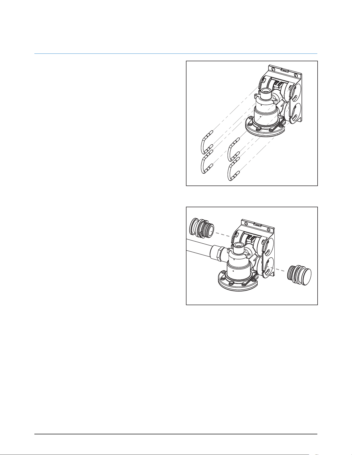
4. Slide the manifold assembly on the system
tting. Slightly rotate the tting for the key
to line up with the manifold and lock in.
5. Secure the tting and manifold assembly
together by installing the yellow U Clips in
the slots (Figure 2).
6. With the manifold assembly in level posi-
tion, mark four mounting holes on the wall
at each corner of the manifold.
7. Remove the manifold assembly from the
tting and drill four pilot holes for the
mounting bolts.
8. Re-attach manifold assembly to tting and
install yellow U Clips to secure in place.
9. Fasten the manifold assembly to the wall
using four bolts (not included).
10. Install plug ttings on the top left and bot-
tom right of the manifold assembly, using
two yellow U Clips to lock them in place
(Figure 3).
11. Install outlet tting to top right of the
manifold assembly (gauge optional) and
secure with a yellow U Clip.
FIGURE 2. SECURE MANIFOLD
FIGURE 3. INSTALL PLUG FITTINGS
12. Using appropriate adapters (not included),
connect the manifold outlet to water pipe.
13. With the cartridge label facing slightly to
the left, insert the cartridge into the head
assembly and turn to the right quarter turn
until fully seated.
56000.0500 B
7/21 © 2021 Bunn-O-Matic Corporation
Page 11
www.bunn.com
803426
SYSTEM STARTUP
1. Check all connections to make sure they
are secure, including all U Clips at each
tting on the manifold assembly.
2. Open the ush ball-valve on the ltration
system ensuring the drain tubing is direct-
ed to a drain or a container.
3. Turn on the water supply to the system.
4. Flush the cartridge(s) by running water for
ve minutes through the system. This will
purge any trapped air and nes.
NOTE: The WQ model is equipped with
unique patented Filter Integrity Ports, which
can indicate if there is an issue with the car-
tridge. For more information about the Filter
Integrity Ports, refer to the Maintenance sec-
tion of this manual. During the initial startup
of the system, a slight amount of water may
weep out of the ports (Figure 4). This is typical
during system pressurization phase.
5. Close the flush ball-valve and turn on power
to equipment.
6. Check for leaks.
FIGURE 4. FILTER INTEGRITY PORTS
INSTALLATION (CONTINUED)
56000.0500 B
7/21 © 2021 Bunn-O-Matic Corporation
Page 12
www.bunn.com
803426
MAINTENANCE
Routine maintenance of this system involves
periodic lter changes. The manufacturer rec-
ommends regularly scheduled maintenance
and replacement of lter cartridge(s) in order to
ensure optimum performance of the ltra-tion
system and equipment that it services.
Filter cartridges shall be replaced when noted
capacity is reached or when low pressure is in-
dicated on the manifold outlet pressure gauge,
whichever occurs rst. Depending on local water
quality, you may need to change the cartridges
prior to the recommended change-out. The loss
of ow to carbonators or improper ll at the ice
maker are also indicators that the cartridges will
need to be replaced. The manufacturer shall not
be liable for equipment failure due to improper-
maintenance of ltration system.
Check performance data sheet or cartridge
label for specic performance information.
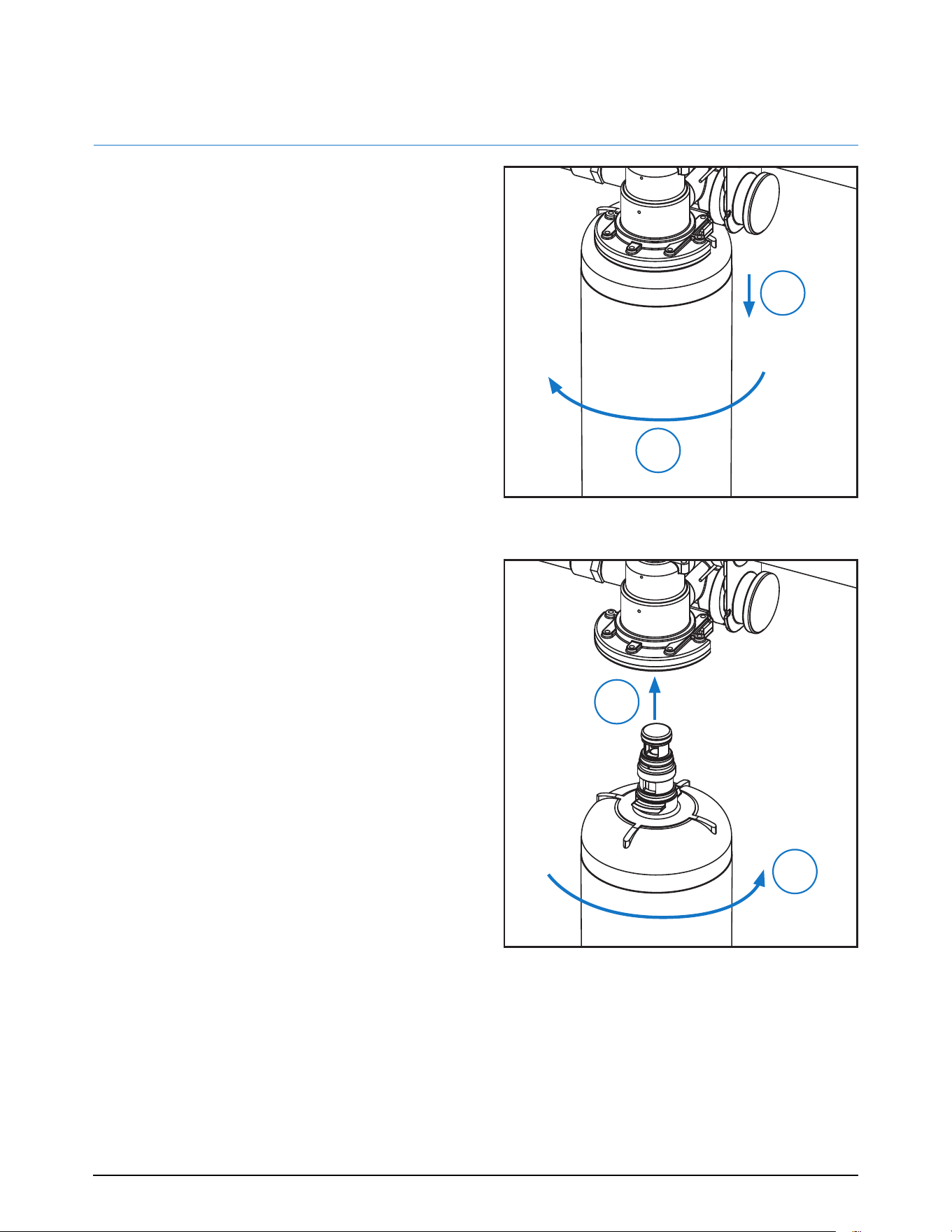
REMOVING A CARTRIDGE
1. Shut off the water supply to the system.
2. Holding the cartridge with both hands,
swiftly rotate the cartridge quarter turn to
the left until disengaged (Figure 5).
3. Discard old cartridge
INSTALLING A CARTRIDGE
1. Install the lter into the manifold by insert-
ing it into the manifold head and swiftly
turning it quarter turn to the right (clock-
wise) until it fully seated (Figure 6).
NOTE: Remove all plastic wrapping and dust
caps prior to lter installation.
2. Write the date the lter was installed in
the designated box on the lter canister.
3. Turn on the water supply to the system.
NOTE: A small amount of water may weep out
of the Filter Integrity Ports while the ltration
system pressurizes.
FIGURE 6. INSTALLING CARTRIDGE
FIGURE 5. REMOVING CARTRIDGE
1
2
2
1
4. Check the system for leaks.
5. Flush the cartridge(s) by running water for
ve minutes through the system. This will
purge any trapped air and nes from the
system.
56000.0500 B
7/21 © 2021 Bunn-O-Matic Corporation
Page 13
www.bunn.com
803426

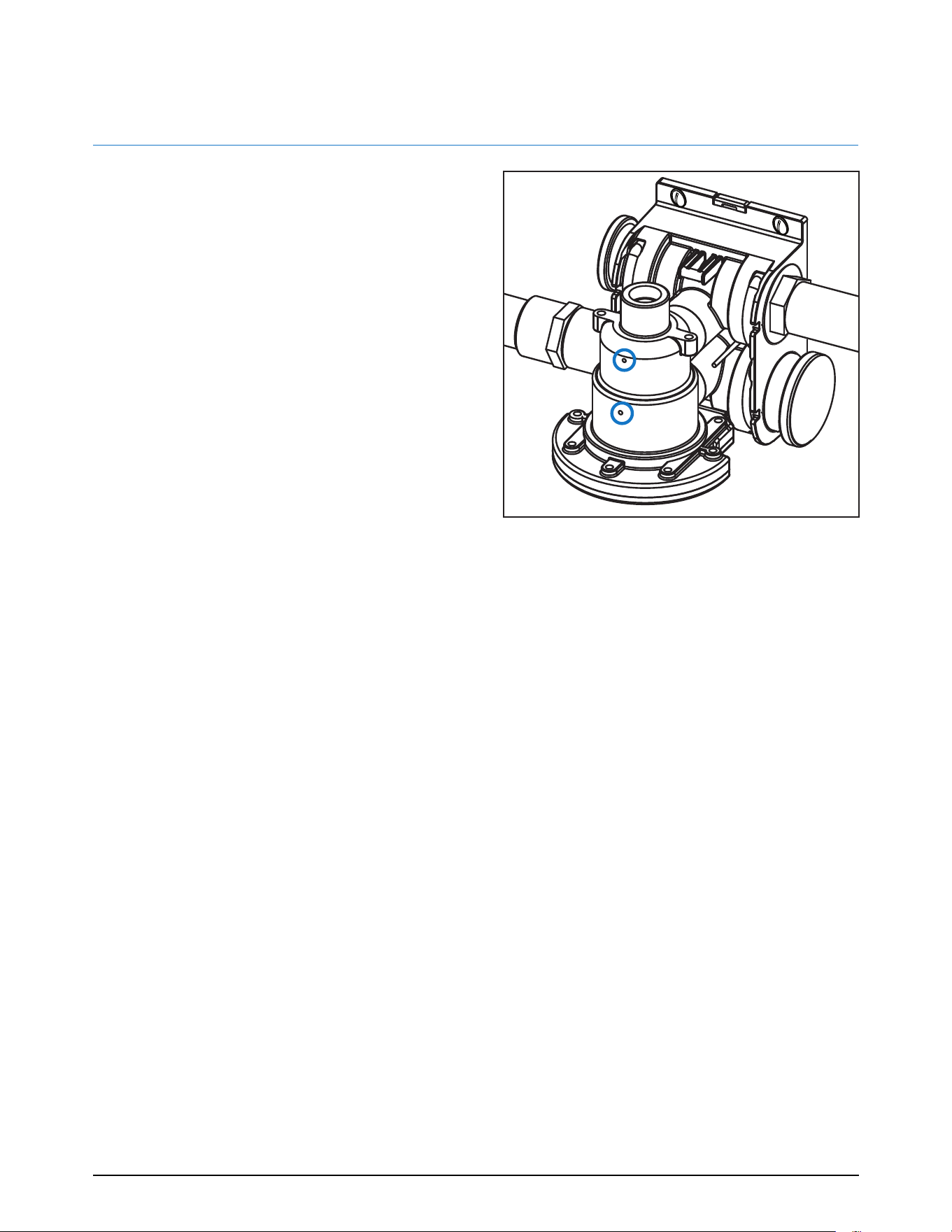
OVERVIEW
The WQ model is equipped with unique pat-
ented Filter Integrity Ports, which can indicate
if there is an issue with the cartridge. If there
is an issue with the cartridge, water will slowly
but continuously weep out of one of the two
ports.
UPPER PORT
If water weeps out of the Upper Port, there is
a possible failure with the cartridge’s O-Ring.
Inspect and replace the O-Ring as needed.
LOWER PORT
If water weeps out of the Lower Port, there is
a possible internal failure with the cartridge.
For example, if a cartridge suffers carbon block
damage during transit or handling, a small
amount of water will slowly but continuously
weep out of the Lower Port on the head as-
sembly. In this case, a new cartridge must be
installed.
FILTER INTEGRITY PORTS
FIGURE 7. FILTER INTEGRITY PORT
56000.0500 B
7/21 © 2021 Bunn-O-Matic Corporation
Page 14
www.bunn.com
803426

TROUBLESHOOTING
Problem Cause Corrective Action
No water comes out of the
water lter system.
Filter(s) are plugged. Replace lter(s).
Vapor-lock. Rinse system.
Low ow from the water lter
system.
Partially plugged lter(s). Replace lter(s).
Barrel valve partially closed. Rotate lter to fully open position.
Water has carbon nes. All carbon lters have carbon nes
on startup.
Rinse system.
Filter leaks from lter interface. O-Ring is out of position in gland. Inspect O-Ring and set in gland.
Nicked or cut O-Ring(s) on lter. Replace O-Ring or lter.
Missing O-Ring(s) Install O-Ring(s).
Water comes out of the upper
Filter Integrity Port (WQ only).
O-Ring is out of position in gland. Inspect O-Ring and set in gland.
Nicked or cut O-Ring(s) on lter. Replace O-Ring or lter.
Missing O-Ring(s). Install O-Ring(s).
Water comes out of the lower
Filter Integrity Port (WQ only).
Cracked carbon block. Replace lter(s).
Water tastes bad. Cracked carbon block (bypass). Replace lter(s).
Nicked or cut O-Ring(s) on lter. Inspect O-Ring and set in gland.
Pre-lter/scale cartridges are in
parallel.
Change pre/post cartridges to
series.
Biological growth in plumbing. Sanitize plumbing and/or system.
Water leaks from ttings. O-Ring is out of position in gland. Inspect O-Ring and set in gland.
Nicked or cut O-Ring(s) on tting. Replace O-Ring or lter.
Missing O-Ring(s). Install O-Ring(s).
Water leaks from back of mani-
fold/wall.
O-Ring is out of position in gland. Inspect O-Ring and set in gland.
Nicked or cut O-Ring(s) on tting. Replace O-Ring or lter.
Missing O-Ring(s). Install O-Ring(s).
Water leaks from barrel valve. Improper the assembly of barrel
valve sub-assembly.
Replace the barrel valve sub-
assembly.
Pressure gauge indicates 0 psi. Water is turned off. Turn water on.
Pressure gauge has failed. Replace pressure gauge.
Rinse valve is leaking. Open/close lever not closed. Close open/close lever all the way.
Rinse valve failure. Replace rinse valve.
56000.0500 B
7/21 © 2021 Bunn-O-Matic Corporation
Page 15
www.bunn.com
803426
EXPLODED VIEW
14
15
16
4
6
3
5
10
12
18
19
20
See next page for complete parts list.
56000.0500 B
7/21 © 2021 Bunn-O-Matic Corporation
Page 16
www.bunn.com
803426

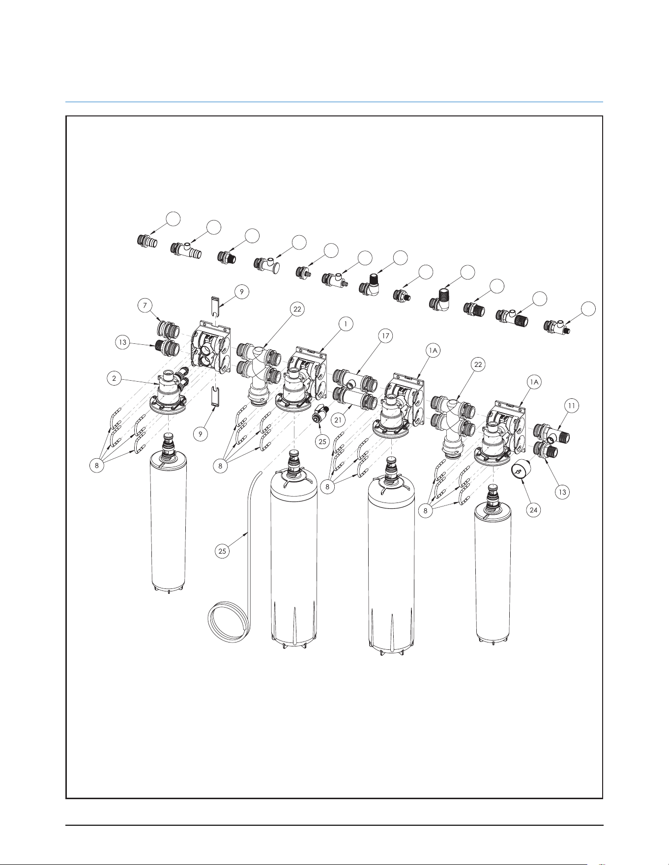
EXPLODED VIEW DESCRIPTION
Page 17
Description
BUNN Part # Quantity Per
1a
MANIFOLD ASSY, WQ HEAD & CLIPS
56000.0404 4
1b MANIFOLD ASSY, WEQ HEAD & CLIPS 56000.0405 4
2a HEAD ASSY, WQ 56000.0406 1
2b HEAD ASSY, WEQ 56000.0407 1
3 ELBOW, 1" MNPT 56000.0408 8
4 ELBOW, 3/4" MNPT 56000.0409 8
5 CONNECTOR, 1" MNPT 56000.0410 8
6 CONNECTOR, 3/8" MNPT 56000.0411 8
7 PLUG, END 56000.0412 8
8 CLIPS, U BLUE 56000.0413 40
9 CLIPS, REAR BLUE 56000.0414 20
10 CONNECTOR, 1" MNPT W/PR PORT 56000.0415 8
11 CONNECTOR, 3/4" MNPT W/PR PORT 56000.0416 8
12 CONNECTOR, 3/8" MNPT W/PR PORT 56000.0417 8
13 CONNECTOR, 3/4" MNPT 56000.0418 8
14 PLUG END W/PR 56000.0419 8
15 FITTING, 1/2" BARBED 56000.0420 8
16 FITTING, 1/2" BARBED W/PR PORT 56000.0421 8
17 FITTING, UNION W/PR PORT 56000.0422 8
18 FITTING, 1" PEX 8 PER 56000.0423 8
19 FITTING, 1" PEX W/PR PORT 56000.0424 8
20 FITTING, 3/4" BSPP 56000.0425 8
21 FITTING, UNION 56000.0426 8
22 FITTING, SERIAL PORT 56000.0427 4
24 GAUGE, WATER FILTER WEQ/WQ 56000.0400 6
25 VALVE, 1/4" MNPT RINSE 56000.0428 6
56000.0500 B
803426
7
/21 © 2021 Bunn-O-Matic Corporation
www.bunn.com

18
NOTES
56000.0500 B
7/21 © 2021 Bunn-O-Matic Corporation
Page 18
www.bunn.com
803426

NOTES
56000.0500 B
7/21 © 2021 Bunn-O-Matic Corporation
Page 19
www.bunn.com
803426

CORPORATE HEADQUARTERS
5020 Ash Grove Drive, Springfield, IL USA 62711
(+1) 217-529-6601 • (800) 637-8606
www.bunn.com
Water_Filtration_Cover_03_23_20.indd 1Water_Filtration_Cover_03_23_20.indd 1 3/24/20 3:11 PM3/24/20 3:11 PM