Commercial Ice Machine
Stainless Steel Air Cooled Commercial Ice
Machine
USER MANUAL
Before using, please read the operating instructions carefully to
ensure proper application and achieve satisfactory results.
For any service related issues, please contact us:
718-576-6342
suppor[email protected]
Model: KM-CIM-500
Stay informed with the latest information for your
KoolMore Reserve Appliance.
Scan the QR code above to access the most recent user manual
on our website, which is constantly being updated and improved.
If you need any assistance or have questions, our customer support
team is here to help.
P- 718-576-6342 E- Suppor[email protected]
Please write down the model number and serial number below for future reference. Both numbers are located on the
rating label on the back of your unit or inside of the unit and are needed to obtain warranty service. You may also
want to staple your receipt to this manual as it is the proof of your purchase and may also be needed for service
under warranty.
Model Number:
Serial Number:
Date of Purchase:
To better serve you, please do the following before contacting customer service:
If you received a damaged product, immediately contact the retailer or dealer that sold you the product.
Read and follow this instruction manual carefully to help you install, use, and maintain your unit.
Refer to the Troubleshooting section of this manual as it will help you diagnose and solve many common issues.

3
Contents
Safety ............................................................................................ 4
Installation .................................................................................... 6
Operation .................................................................................... 10
Maintanence ................................................................................ 14
Troubleshooting ........................................................................... 23
Warranty ....................................................................................... 24

4
Safety
DANGER – FIRE OR EXPLOSION HAZARD:
• This appliance contains ammable refrigerant. Repairs must be carried out only by trained ser-
vice personnel. Do not puncture any refrigerant tubing.
CAUTION – FIRE OR EXPLOSION HAZARD:
• This appliance uses ammable refrigerant. Before servicing, refer to the repair manual or own-
er’s guide. Always follow all safety precautions.
CAUTION – RISK OF FIRE OR EXPLOSION IF REFRIGERANT TUBING IS PUNCTURED:
• Handle with care and follow all handling instructions. This unit contains ammable refrigerant.
CAUTION – FIRE OR EXPLOSION HAZARD DUE TO FLAMMABLE REFRIGERANT:
• Follow all handling guidelines carefully and in accordance with local regulations.
This appliance should not be used by individuals (including children) with reduced physical, senso-
ry, or mental capabilities, or those lacking experience and knowledge, unless they are supervised
or have been instructed by a person responsible for their safety.
Children must be supervised to prevent them from playing with the appliance.
Do not store explosive items, such as aerosol cans with ammable propellants, in this app
WARNING:
• Ensure all ventilation openings in the appliance or surrounding structure remain unobstructed.
• Only use defrosting methods recommended by the manufacturer; do not use mechanical or
alternative methods.
• Do not damage the refrigerant circuit.
• Do not use electrical devices inside the food or ice storage compartments unless they are ap-
proved by the manufacturer for such use.
Safety Tips
This appliance is classied as Climatic Class 4. The meaning of Class 4 is explained below:
Test room Dry bulb temperature Relative humidity Dew point Water vapour mass in
dry air climate class
0F % 0F g/kg
4 86 55 68,32 14,8
Flammable refrigerant is used in this appliance. It must be installed in compliance with the ANSI/
ASHRAE 15 Safety Standard for Refrigeration Systems.
5
The triangle warning symbol indicates: “Warning – Risk of re / presence of amma-
ble materials.”
The symbol means connection to a potable (drinking) water supply.
WARNING – Flammable refrigerant in use. All replacement components must be of
the same type to reduce the risk of re or ignition caused by incorrect parts.
If the power cord is damaged, it must be replaced by the manufacturer, an autho-
rized service agent, or a similarly qualied technician to avoid any safety hazards.
Always use the new hose sets provided with the appliance. Do not reuse old hose
sets.
WARNING –
• Do not use any methods to accelerate the defrosting process or to clean the appliance other
than those recommended by the manufacturer.
• The appliance must be stored in a room without any continuously operating ignition sources,
such as open ames, gas appliances, or electric heaters.
• Do not pierce or burn the appliance.
• Be aware that refrigerants may be odorless and not detectable by smell.
• Ensure all required ventilation openings are kept clear and unobstructed.
6
Installation
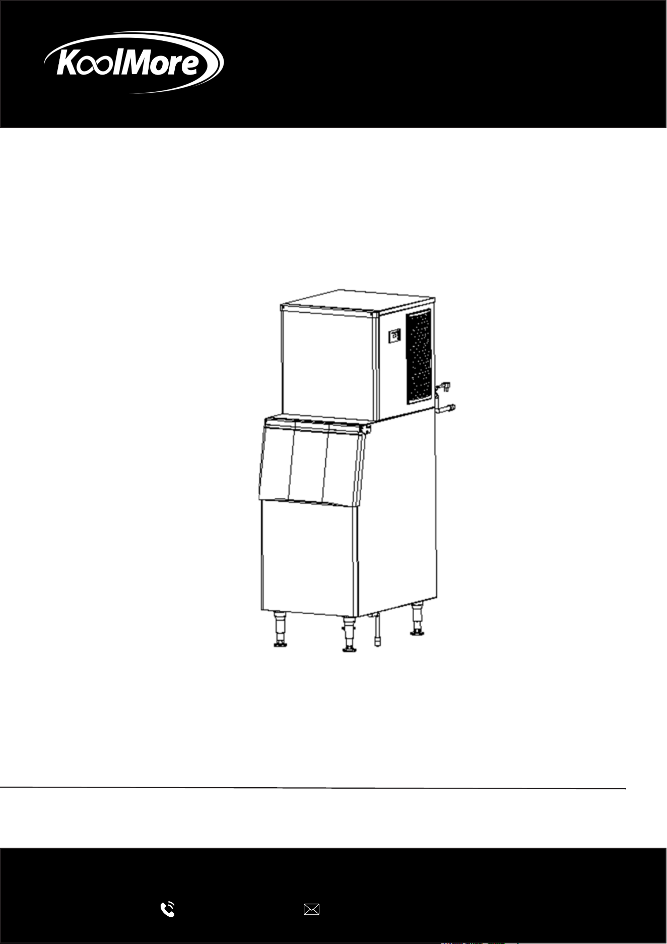
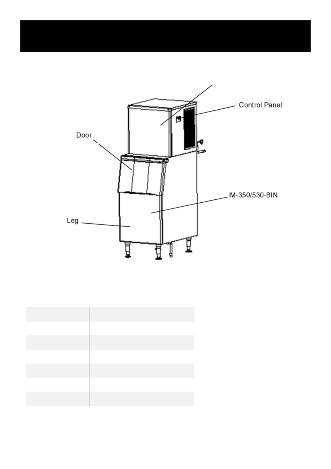
1. Assembly
KM-CIM-500
[KM-CIM-500]
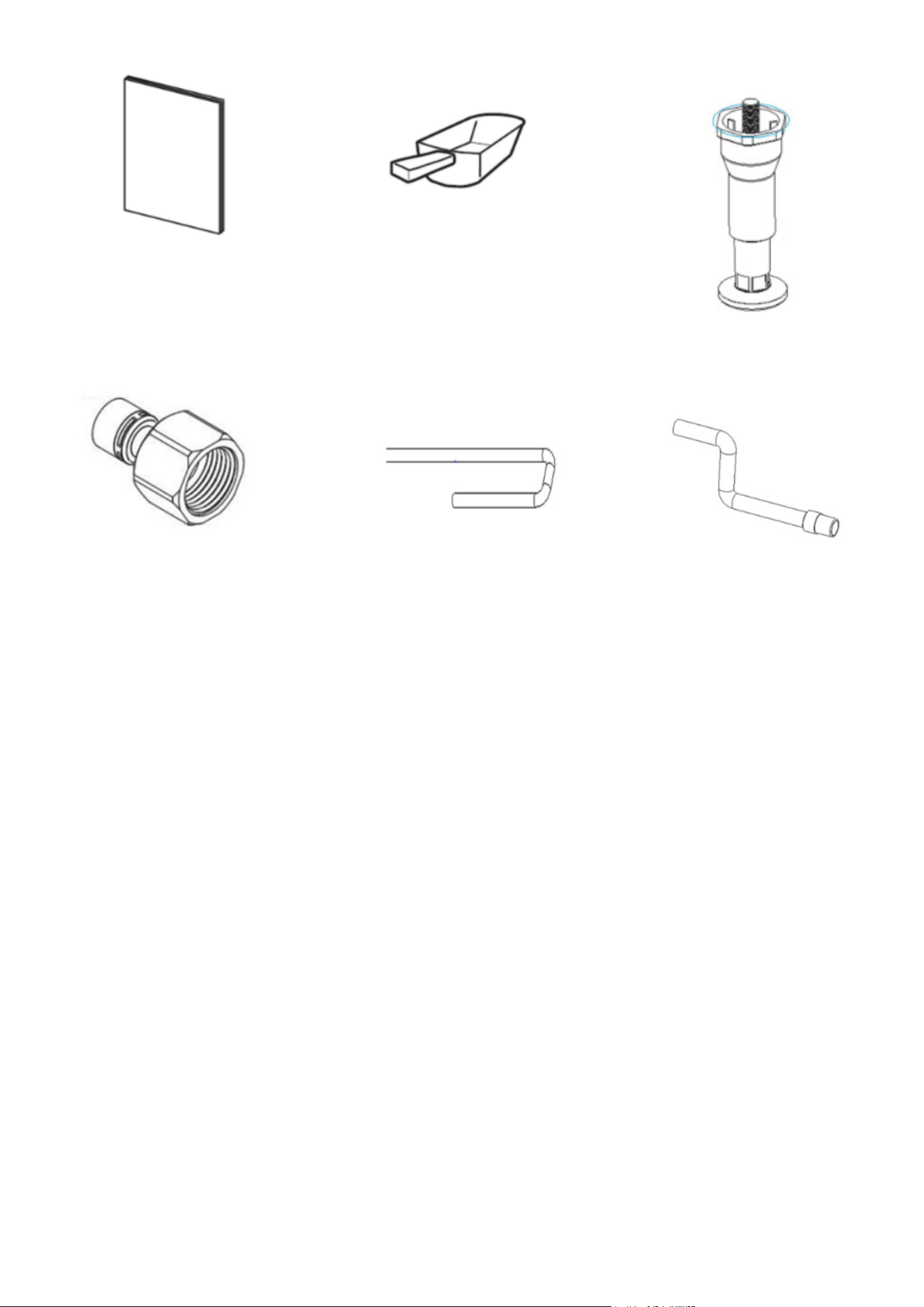
2. ACCESSORIES
Accessory KM-CIM-500
Instruction Manual 0
Scoop 1
Leg 4
Connector 6
Inlet pipe 2
Drain-pipe 1
7
Instruction Manual
Scoop
Leg
Connector Inlet pipe Drain-pipe
3. UNPACKING
• Indoor Use Only: This product is not designed for outdoor use. It is not intended for use by chil-
dren, individuals with reduced physical, sensory, or mental abilities, or those lacking experience
and knowledge, unless supervised or instructed by a responsible person.
• Professional Installation Required: Installation, repair, and maintenance must be carried out by
qualied professionals. Improper handling may result in electric shock, re, or personal injury.
• After Delivery: Keep the ice machine upright for at least 24 hours before turning it on. This
allows the refrigerant to fully settle and prevents compressor damage.
• During Transport: Always keep the machine upright, and ensure it is tilted no more than 45
degrees. Do not lay the machine horizontally or upside down. Avoid placing it in wet or splash-
prone areas.
• Proper Grounding: The appliance must not be grounded to gas lines, water pipes, telephone
lines, or lightning rods.
• Moving Parts Hazard: This machine contains rotating components. Do not insert any objects
into the ventilation or exhaust openings, as it may cause serious mechanical damage or injury.
• Flammable Materials Warning: Do not store ammable or volatile substances inside the ma-
chine. Doing so may lead to re or explosion.
• Storage Bin Use: Do not store miscellaneous items or food in the ice storage bin. Keep the ice
scoop clean at all times.
• Stable Placement: The ice machine must be placed on a solid, level surface capable of sup-
porting its weight. An unstable base could cause the unit to tip over and result in injury.
• Ventilation Clearance: Ensure there is adequate ventilation space around the machine. Refer to
page 6 for specic clearance requirements.

8
• Correct Power Supply: Use only the power source specied on the appliance’s nameplate.
• Do Not Connect to Hot Water: This machine must be connected to a cold water supply only.
• Proper Electrical Outlet: The outlet must be properly grounded and equipped with leakage
protection.
• Power Disconnection: Always disconnect the power supply before performing manual clean-
ing, repairs, or maintenance.
• Before performing cleaning, repairs, or maintenance, make sure to remove all remaining ice
from the bin to prevent contamination.
• Do not spray water directly onto the surface of the ice machine during cleaning, as this may
lead to short circuits, electrical leakage, or equipment damage.
• A ammable foaming agent is used during the insulation process. Disposal and recycling of
the ice machine must be carried out by authorized personnel or certied facilities.
• Ensure the ice machine is not accessible to children, and take proper measures to prevent
them from playing with or operating it.
• In the event of a malfunction, immediately switch off the power and contact a qualied techni-
cian for repairs.
4. Water lters
• Water lters are designed for use with standard restaurant equipment to ensure the water sup-
plied is both clean and free of impurities.
5. Location
• Power Supply: Use a voltage that matches the machine’s nameplate rating, with a tolerance of
±6%.
• Water Source: Only connect to potable water with a pressure range of 18–80 psig and a tem-
perature between 41°F and 89.6°F.
• Keep the ice machine away from heat sources and ensure safe operation at all times.
• Avoid placing the machine in extremely hot or cold environments and protect it from direct
sunlight.
• Ensure adequate ventilation space around the machine:
At least 12 inches (30 cm) at the front
At least 6 inches (15 cm) on each side
At least 8 inches (20 cm) at the rear
• Place the machine on a solid oor capable of supporting its full weight.
• The power outlet must be properly grounded and equipped with leakage protection.
• Provide proper oor drainage near the installation site to handle any water discharge.
6. Installation Steps
1. Inspection:
Check that the ice machine is in good condition and that all accessories are included. Verify
the machine model and details on the nameplate.
2. Initial Cleaning:
Clean the ice storage bin and internal food-contact surfaces using a sponge soaked in warm
water and mild soap. Rinse thoroughly with potable water and dry with a clean cloth.
3. Placement:
Position the ice machine in the designated operation area. Ensure it is placed on a level surface
to allow proper water ow into the evaporator.
9
4. Ventilation Requirements:
The compressor and condenser are located in the chamber beneath the front of the bin. Ensure
proper airow by maintaining at least 8 inches (20 cm) of clearance at the rear, 6 inches (15
cm) on both sides, and 12 inches (30 cm) at the front.
5. Level Adjustment:
The base of the machine includes adjustable legs, allowing for precise leveling and adequate
oor clearance for cleaning.
6. Water Filter and Line Connection:
Connect the water lter and inlet line according to the water lter manufacturer’s instructions.
If a drinking water system is already installed, a separate lter may not be required.
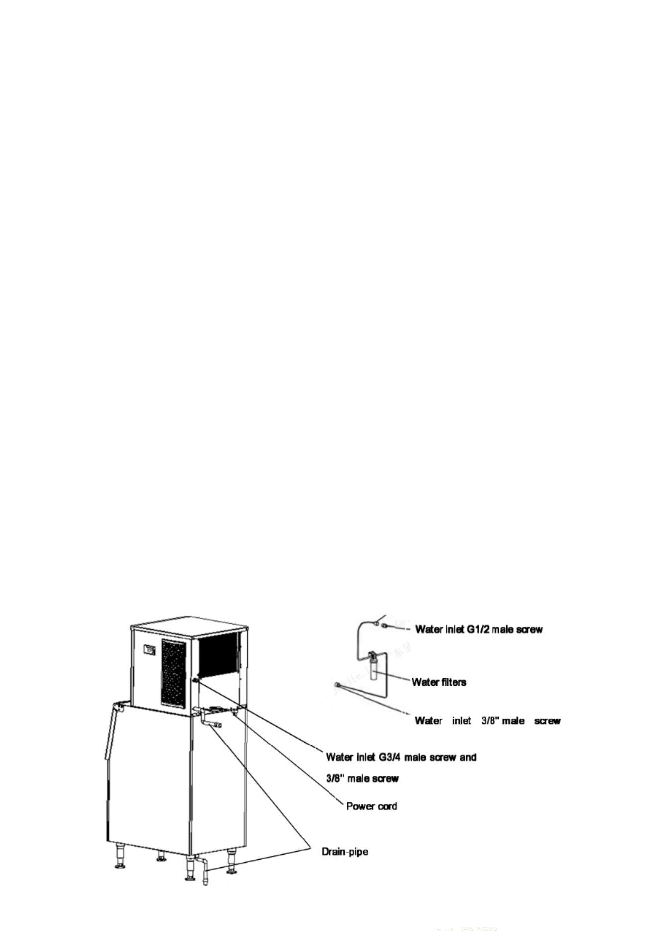
7. Water Supply Connection:
Attach the water supply using the 3/4” inlet tting provided. Installing a ball valve on the water
line (not included) is recommended for easier shut-off.
8. Drainage Connection:
Connect the drain line to the machine’s drain outlet. For optimal drainage, maintain a slope of
more than 1 inch per 3 feet of pipe. Ensure the line is free of blockages and ideally leads to an
open drainage port.
9. Drain Line Positioning:
No part of the drain line should be higher than the drain port of the machine, and joints must
not be placed higher than any previous connection.
10. Power Requirements:
Conrm the power specications on the nameplate and ensure the electrical supply matches
those requirements.
11. Circuit Protection:
A dedicated circuit breaker or power switch with leakage protection and proper grounding is
required.
12. Power Connection:
Switch off the power before connecting the machine to the power source.
Note: Install the water lter in the correct direction, as indicated by the arrow on the lter head
or body. Replace the lter cartridge every 3 to 6 months for optimal performance.
13. Refer to Schematic Diagram:

10
Operation
1. Start-up
1. Pre-Startup Inspection:
Before switching on the machine, please ensure the following:
• All packaging materials and tape inside the machine have been removed.
• Any accessories or items in the ice bin have been taken out.
• The machine is placed on a level surface.
• The water line is properly connected and the water valve is open.
• The machine is plugged into the power supply, but the power switch is turned off.
• The ambient temperature, water temperature, and water pressure meet the recommended op-
erating conditions.
2. Powering On the Machine:
Turn on the power switch. Once powered on, the machine will automatically begin the ice-making
process.
3. Conrming Normal Operation:
Check the following to ensure the machine is functioning correctly:
• The water trough is lled, and there are no overows.
• The water pump is working, with water owing evenly over the evaporator.
• The compressor is running, and both the evaporator temperature and water temperature are
steadily decreasing.
• For air-cooled models, ensure the fan is operating and there is consistent airow through the
air intake and exhaust vents.
• There are no unusual noises during operation.
• There are no abnormal vibrations from the machine.
• Ice production time ranges between 10 to 20 minutes per batch, depending on environmental
and water temperatures—higher temperatures may increase cycle time.
• Ice cubes are being properly formed and released from the machine.
2. Operation
• Startup:
Once the machine is correctly installed, connect the water supply and turn on the power. En-
sure the machine is functioning properly during its initial startup.
• Self-Check:
When powered on for the rst time, the ice machine will automatically perform a self-diagnos-
tic check.
• Preparation Phase:
After the self-check is complete, the water inlet valve opens, allowing water to ll the system.
Simultaneously, the machine will perform an initial defrost cycle.
• Ice Making:
After a 30-second pre-cooling period, the water pump activates, circulating water evenly over
the evaporator. Ice begins to form gradually in the ice cube trays.
11
• Ice Harvesting (Ice Drop):
Once the ice-making cycle ends and the pump stops, the defrost valve opens. Hot gas ows
into the evaporator for approximately 1–2 minutes, causing the ice cubes to release and fall
into the storage bin.
Warning: Do not insert your hands into the ice bin during this process to avoid injury from fall-
ing ice.
• Shutdown:
To stop the machine during operation, press the “Standby” button on the control panel.
• Bin Full Auto-Stop:
When the ice bin reaches full capacity, the machine automatically stops ice production. A sen-
sor located at the ice guide detects when the bin is full.
To maximize storage space, evenly distribute the piled-up ice in front of the sensor.
• Automatic Restart:
Once the ice level drops below the sensor (e.g., after removing ice), the machine will automati-
cally resume ice production within a few seconds.
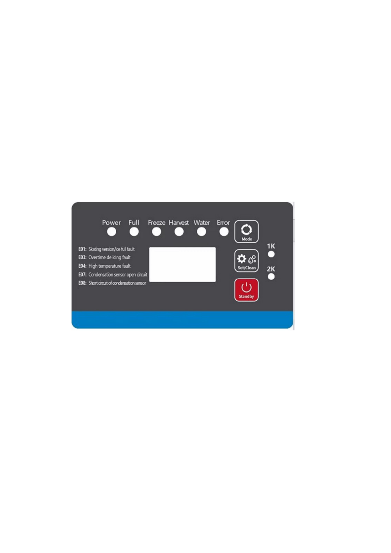
3. Control Panel
1. LED Display Functions:
• Preparing Mode:
Displays a forward counting timer in seconds while the machine prepares.
• Ice Making Mode:
Displays “Freeze” along with a forward counting timer in seconds.
• Ice Harvesting Mode:
Displays “Harvest” with a forward timer in seconds during the ice release process.
2. Adjusting Ice Cube Thickness:
• During ice production, if you want to change the ice cube thickness:
Press the “Set/Clean” button, then use the “Mode” or “Set/Clean” buttons to adjust the thick-
ness.
• Each press of the button will increase or decrease the ice-making time by 1 minute, which di-
rectly affects the ice thickness.

12
3. Cleaning Mode:
• To activate the cleaning cycle:
Press and hold the “Set/Clean” button for 6 seconds during normal operation.
• Add the appropriate cleaning and sanitizing agents into the water tank during this process.
• Once cleaning is complete, the machine will automatically resume ice-making.
Note: Only use nickel-safe cleaning and sanitizing chemicals.
4. Standby Mode:
Press the “Standby” button to pause machine operation.
5. Storage Bin Usage:
Always open and close the bin door gently—avoid slamming. Keep the door closed when not re-
trieving ice to maintain optimal temperature and hygiene.
6. Long-Term Inactivity:
If the ice machine will not be used for an extended period, it should be powered on and run for 2 to
4 hours every 2 months to maintain functionality.
4. Other Special Protection
• If the ice machine fails to detect an ice harvest for three consecutive cycles, it will automatical-
ly shut down as a safety precaution. The unit should be inspected and serviced.
• If the ambient temperature exceeds a safe operating range, the machine will stop operation to
prevent damage and ensure safety.
• Fault codes and their descriptions will be displayed as follows:
Code
Fault
1. The ice guide is missing
2. The ice full switch is faulty
3. The magnetic induction element
is reversed polarity
E01
Ice guide or Ice Full
Switch Fault
Cause
Action
Inspection and repair
1. The hot gas valve is faulty
2.The condensing temperature is low
3.The ice set is too thin
4.The water volume is too low
E03
Overtime Deicing
1.Check the hot gas valve
2.Circuit or water intake system
1.The fan motor is not functioning
2.Air lter or condenser is dirty
3.Ambient temperature is too high
E04
High System Temp.
Fault
1.Check if the fan blade is stuck, if
not, please replace the fan.
2. Please clean air lter or
condenser
The condensation temperature is too
high or the cooling system is blocked
E06
Over System Pressure
1.Check if the fan does not work, If
the cooling fan works properly, the
high pressure switch maybe faulty.
Use a multimeter to measure the
on/off status of the pressure
switch.
2. check if the cooling system is
blocked

13
Code
Fault
The sensor is damaged or the con-
nector is faulty
E07
Cond. Temp. Sensor
Open Fault
Cause
Action
Verify probe wires have a good
connection in the controller by dis-
connecting probe leads from con-
troller and reconnecting leads to
controller Use a multimeter set to
Ohm setting and verify resistance
valve of the probe in 77F hot water.
Value should be with 10 kΩ±1%.
The sensor is damaged or the connec-
tor is faulty
E08
Cond. Temp. Sensor
Short Fault
Verify probe wires have a good con-
nection in the controller by discon-
necting probe leads from
controller and reconnecting leads
to controller Use a multimeter set
to Ohm setting and verify resis-
tance valve of the probe in 77F
hot water. Value should be with 10
kΩ±1%.

Cleaning
NOTE: Maintenance must be done by a qualied technician.
WARNING:
Always turn off the water supply and power before performing any maintenance or manual clean-
ing.
Exterior Cleaning
• Regularly clean the area around the ice machine to maintain a clean environment.
• Ensure that ventilation openings are not blocked.
• Wipe the exterior with a mild detergent and a soft cloth.
For stainless steel surfaces, use appropriate stainless steel cleaners and polish if needed.
Note: Without proper care, stainless steel surfaces can rust over time.
Water Filter Maintenance
If a water lter is installed, inspect it regularly.
It’s recommended to replace the lter cartridge every 3 to 6 months.
Interior Cleaning
Clean the inside of the ice bin using water and a cleaning solution.
Rinse thoroughly, then sanitize using a water and sanitizer solution.
Important: Ensure that water pressure is within the recommended limits.
Do not spray water directly on components above the water pump or evaporator to avoid damage.
Condenser Cleaning (Air-Cooled Models)
Clean the condenser once a month.
Use a soft brush or vacuum with a brush attachment, brushing in the direction of the ns to avoid
damage.
The condenser lter should be cleaned every 2 weeks.
Caution: The edges of the condenser ns are sharp—handle with care.
Water Pipe Cleaning
For food safety, clean the ice machine’s water pipes regularly.
Winterizing Instructions
Before winter or extended non-use, turn off the power and water supply.
Drain all remaining water from the water trough, inlet pipe, and drain pipe.
Note: Routine maintenance is not covered under the manufacturer’s warranty.
14
Maintanence
15
Monthly Clean Function
Important Notes Before Starting:
• Ensure the ice bin is emptied in advance.
• Thoroughly clean and sanitize the ice bin, followed by a complete rinse.
• Clean and sanitize the ice guide, water pipe, and water pump, then rinse thoroughly.
Cleaning Process
• Turn on the ice maker.
• Press and hold the “Set/Clean” button for 6 seconds to initiate the cleaning cycle.
• The water valve will run for approximately 85 seconds (this duration is adjustable) to reach the
normal water level.
• Manually add the appropriate amount of cleaning solution into the water tank and spray it di-
rectly onto the evaporator for effective cleaning.
• The water pump will run for 15 minutes. After the rst 5 minutes, add the recommended
amount of disinfectant into the water tank and spray the evaporator, following the instructions
provided with the disinfectant.
• Both the water pump and valve will run for another 15 minutes to complete the rinsing cycle.
• Once the cleaning process nishes, the ice maker will automatically resume ice production.
• Discard the rst batch of ice after cleaning to ensure no cleaner residue remains.
• Always follow the manufacturer’s guidelines for mixing and applying cleaning agents and sani-
tizers.
Monthly Manual Cleaning & Sanitizing
Attention:
• Monthly manual cleaning and sanitizing must be performed by the manufacturer, an authorized
service agent, or other qualied personnel.
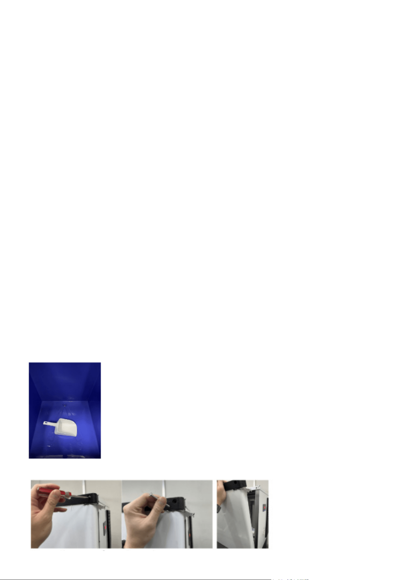
Cleaning Guidelines
1. Clear all ice from the storage bin to prevent contamination.
2. Remove the door.
16
3. Drain the water from the tank.
4. Take out the pump and disconnect the upper circulation pipe from it.
5. Unscrew the fasteners holding the spray pipe in place. Remove both the spray pipe and the up-
per pipe.
6. Loosen and remove the screws on the spray pipe to fully dismantle it.
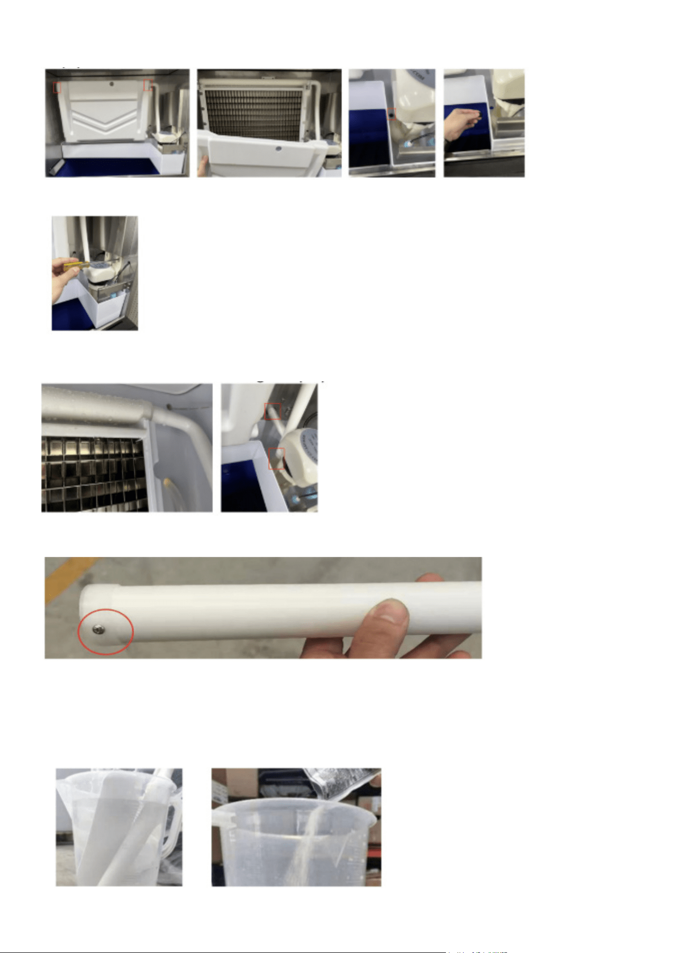
7. Prepare a cleaning solution by mixing cleaner and water according to the instructions provided
with your ice machine cleaner. Make sure the cleaner is fully dissolved. Soak the water pipe, inlet
and outer spray pipes, spray head, pipe mounting bracket, screws, and other components in the
solution for 5 minutes (or 15 minutes if there is heavy scale buildup). Rinse all parts thoroughly
with clean water.
17
8. After soaking, scrub the spray pipe, water curtain, and pump base bracket using the cleaning
solution, then rinse them well with clean water.
9. Spray the cleaning solution onto the evaporator and wipe it clean. Use the solution to wipe down
the water tank, ice plate, its plastic components, side panels, ice bucket, and other sanitary surfac-
es. Rinse all cleaned areas thoroughly with fresh water.
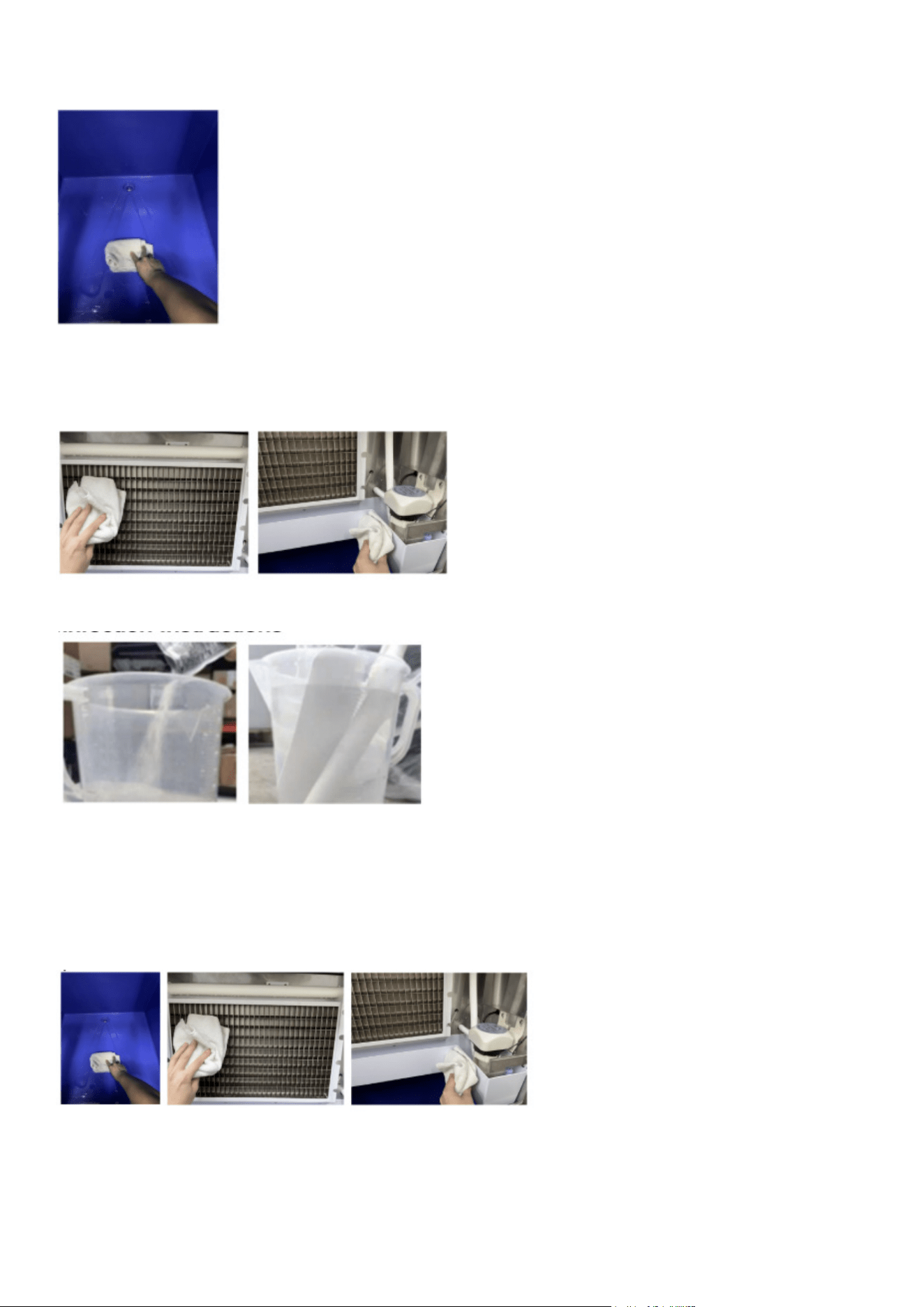
Disinfection Instructions
1. Prepare a disinfectant solution by mixing disinfectant with water as per the ice maker’s disin-
fectant instructions. Ensure it is fully dissolved. Soak the water pipe, inner and outer nozzles,
nozzle head base, and screws in the solution for 5 minutes. If a no-rinse disinfectant is used,
rinsing is not necessary.
2. Apply the disinfectant to the spray pipe, ice guide, and pump support. If using a no-rinse disin-
fectant, ushing these parts is not required.
1. Use a spray bottle to apply disinfectant to the evaporator and its plastic components. Also,
spray the water tank, ice bin, and other sanitary areas. If a no-rinse disinfectant is used, rinsing
is not required.
2. Let the disassembled spray pipe, water pump, water pipe, and ice guide dry completely before
reinstalling them in their original positions.

18
Warnings for ammable refrigerants
Servicing Guidelines
All servicing must be performed strictly according to the manufacturer’s recommendations.
Personnel Qualication
Only qualied and competent individuals should perform any task that impacts safety. Personnel
involved in maintenance, servicing, or repairs must be properly trained and certied.
Examples of such tasks include:
a) Opening the refrigeration circuit
b) Disassembling sealed components
c) Accessing ventilated enclosures
Pre-Work Area Inspection
Before starting any work on systems containing ammable refrigerants, conduct safety checks to
reduce the risk of ignition.
Controlled Work Procedure
Work must follow a controlled process to minimize the chance of ammable gases or vapors be-
ing present during operations.
General Work Environment
All personnel in the vicinity must be informed of the nature of the work. Avoid conducting tasks in
conned spaces whenever possible.
Refrigerant Detection
Use a suitable refrigerant detector to monitor the area before and during maintenance. This en-
sures the technician is aware of any potentially hazardous or ammable atmospheres. The leak
detector must be non-sparking, properly sealed, or intrinsically safe, and compatible with the refrig-
erants in use.
Fire Safety
If any hot work (e.g., welding) is required, ensure that appropriate re extinguishing equipment—
such as a dry chemical or CO₂ extinguisher—is available near the working area.
Eliminating Ignition Sources
When working on any refrigeration system, avoid using ignition sources near exposed pipework to
prevent re or explosion risks. This includes preventing activities such as smoking near the equip-
ment.
Before starting work, inspect the surrounding area to ensure there are no ammable materials or
ignition risks. Clearly display “No Smoking” signs around the work area.
Ventilation Requirements
Ensure the workspace is either outdoors or well-ventilated before beginning work on the system or
performing any hot work. Proper ventilation must be maintained throughout the task to disperse
any refrigerant safely, preferably directing it outside into the open air.

19
Refrigeration Equipment Inspection
When replacing electrical components, ensure they are correctly specied and appropriate for their
purpose. Always follow the manufacturer’s service and maintenance guidelines. If uncertain, con-
sult the manufacturer’s technical support.
For systems using ammable refrigerants, perform the following checks:
a) Verify that the actual refrigerant charge complies with the room size where refrigerant compo-
nents are installed.
b) Ensure ventilation equipment and exhaust outlets are functioning properly and are not blocked.
c) If an indirect refrigeration circuit is used, inspect the secondary loop for refrigerant presence.
d) Conrm that all equipment labels and warning signs are visible and legible; replace or restore
any that are not.
e) Ensure refrigerant pipes and components are placed in areas free from corrosive substances,
unless the materials used are corrosion-resistant or properly protected.
Electrical Component Checks
Before performing any electrical maintenance or repairs, conduct initial safety checks and inspect
components. If a safety-compromising fault is found, do not connect the electrical supply until the
issue is fully resolved. If immediate repair is not possible but continued operation is necessary,
apply a safe temporary x and inform the equipment owner accordingly.
Initial electrical safety checks should include:
a) Safely discharging capacitors to avoid sparking.
b) Ensuring no live wires or components are exposed during system charging, purging, or refriger-
ant recovery.
c) Verifying proper continuity of the earth/ground connection.
Repairs to Sealed Components:
Before beginning any work on sealed components, disconnect all electrical power to the equip-
ment being serviced.
If it is absolutely necessary to keep the equipment powered during maintenance, a continuously
operating leak detector must be installed at the most critical location to alert for any potentially
hazardous situations.
Special care must be taken to ensure that working on electrical components does not compromise
the integrity of the equipment’s protective enclosure. This includes avoiding:
• Damage to electrical cables
• Excessive connections or modications
• Use of terminals not matching original specications
• Damage to seals or improper tting of cable glands
Ensure that the equipment is securely mounted and that any seals or sealing materials are still
effective in preventing the entry of ammable gases. All replacement parts must comply with the
manufacturer’s specications.
Repairs to Intrinsically Safe Components:
Avoid applying permanent inductive or capacitive loads to the circuit unless you’re certain the volt-
age and current limits of the equipment will not be exceeded.
Only intrinsically safe components are permitted to be serviced while live in a ammable atmo-
sphere. Ensure the testing equipment used is correctly rated.
Always replace components with those specied by the manufacturer. Using alternative parts may
pose a re risk by igniting leaked refrigerant.

20
Cabling:
Inspect all cabling to ensure it’s not exposed to wear, corrosion, pressure, vibration, sharp edges,
or other environmental hazards. This also includes evaluating aging effects or continuous vibra-
tion from components like fans or compressors.
Detection of Flammable Refrigerants:
Never use ignition sources when checking for refrigerant leaks. Devices such as halide torches or
ame-based detectors are strictly prohibited.
Acceptable leak detection methods include:
• Electronic leak detectors: These may be used but must be suitable for ammable refrigerants.
Ensure they are calibrated in a refrigerant-free area and are intrinsically safe, sealed, and non-
sparking.
• Detection sensitivity: Set detectors to a percentage of the refrigerant’s Lower Flammable Limit
(LFL), not exceeding 25%.
• Leak detection uids: These are acceptable for most refrigerants but avoid those with chlorine,
as they may react with refrigerants and corrode copper pipes.
If a leak is detected, all open ames must be extinguished. If brazing is necessary, remove all re-
frigerant from the system beforehand using proper evacuation procedures.
Removal and Evacuation:
When accessing the refrigerant circuit for repairs or other reasons, follow standard procedures,
with added precautions for ammable refrigerants:
1. Safely extract refrigerant in accordance with local/national regulations.
2. Purge the circuit with inert gas.
3. Evacuate the system (optional for A2L refrigerants).
4. Purge again (optional for A2L).
5. Cut or braze the circuit safely.
Recover refrigerants into designated cylinders (not vented unless allowed by law). For ammable
refrigerants, purge the system with oxygen-free nitrogen. Repeat the purge as needed to ensure no
refrigerant remains. Do not use compressed air or oxygen.
Purge by breaking the system vacuum with nitrogen, raising pressure, venting, and repeating
the vacuum/purge process as needed (especially for A2L). Ensure nitrogen purging is done in
well-ventilated areas away from ignition sources.
Charging Procedures:
In addition to general practices, follow these steps:
• Prevent cross-contamination of refrigerants in charging lines. Keep hoses short.
• Store cylinders in proper positions.
• Conrm the system is grounded before charging.
• Label the equipment after charging.
• Avoid overcharging.
Pressure-test the system before charging, check for leaks after charging but before starting the
system, and do a nal leak check before leaving the site.

21
Decommissioning:
Ensure the technician fully understands the equipment. Recover refrigerants safely and sample
both oil and refrigerant if reuse is intended. Ensure electrical power is available before starting.
Steps:
1. Familiarize with the system.
2. Disconnect electrical power.
3. Prepare:
Handling tools for refrigerant cylinders
Proper personal protective equipment (PPE)
Supervision by qualied personnel
Approved recovery equipment and cylinders
4. Pump down the system if possible.
5. If vacuuming isn’t feasible, install a manifold for refrigerant removal.
6. Weigh cylinders before recovery.
7. Follow equipment instructions during recovery.
8. Do not exceed 80% ll in cylinders.
9. Stay within the cylinder’s rated pressure.
10. Remove cylinders and equipment promptly after recovery and close isolation valves.
11. Do not reuse recovered refrigerant without proper cleaning and testing.
Labelling:
Mark all decommissioned equipment as emptied of refrigerant. Include date and signature. Appli-
ances with ammable refrigerants must also display ammable content labels.
Recovery:
During refrigerant removal (service or decommissioning), always follow safe practices.
• Use only certied recovery cylinders labeled for the specic refrigerant.
• Ensure cylinders have functional shut-off and pressure relief valves.
• Evacuate and ideally cool empty cylinders prior to recovery.
• Use recovery machines in good working condition with instructions readily available.
• Keep a calibrated scale and leak-free hoses with quick-disconnect ttings.
Before use, conrm recovery equipment is maintained and explosion-safe if refrigerant leaks oc-
cur. Contact the manufacturer if unsure.
Return recovered refrigerant to suppliers in proper containers and arrange appropriate waste docu-
mentation. Never mix refrigerants in units or cylinders.
When removing compressors or oils:
• Evacuate thoroughly to ensure no refrigerant remains in the oil.
• Only use electric heating to assist in evacuation.
• Drain oil safely.

22
Service Call
If the ice machine is not functioning properly, please review the following checks before requesting
service:
1. Water Supply Check
• Ensure there is water in the water trough.
• Verify that the water pressure is between 18 psig and 80 psig, and the water temperature is
within 41–89.6°F.
• Conrm that the water valve is fully open.
• Check for any signs of water leakage.
2. Power Supply Check
• Check if the indicator light on the display panel is illuminated.
• Ensure the display does not show the OFF standby mode.
• If the LED is not lit, inspect the plug and socket for proper connection, and conrm that the
power switch is turned ON.
3. Model and Serial Number Check
• Locate and note the model and serial number on the nameplate, which is typically on the side
or back of the ice machine.
Note: If the malfunction is due to user-related issues—such as not using or maintaining a water
lter, lack of water or power supply, or unsuitable environmental conditions—rather than a fault
with the machine itself, service calls may incur a charge.

23
Troubleshooting
Problem
Possible Cause
• Power switch not turned on
Not working
Solution
• Turn on the power switch
• Plug is loose
Indicator is OFF
• Check plug and socket
• The ambient temperature is too
high
Shutdown every 3 min-
utes after startup
• Normal working temperature
range of 41-100.4°F
• The ambient temperature is too
high
The display shows E04
high temperature
• Clean the condenser
• Fan does not start
The display shows E06
high pressure protection
• Check and correct high pressure
switch wires
• Ambient temperature too low
• Defrost valve does not start nor-
mally
• Ice thickness too thin or too thick
Ice defrost abnormal
• Normal working temperature
range of 41-100.4°F
• Check and correct the defrosting
valve
• Check and correct ice thickness
setting
• Ice thickness is too thin
• Water pressure is too low
• Inlet water valve is dirty and
blocked
• inlet water lter has not been
replaced for a long time
• Inlet water valve is dirty and
blocked
• Water leaking
• Inlet water lter has not been
replaced for a long time
Poor transparency of ice
cubes; ice cubes too thin
or incomplete
• Check and correct ice thickness
setting
• Check that the water supply pres-
sure is 18 psig to 80 psig
• Normal working temperature
range of 41-100.4°F
• Check and correct the inlet water
valve
• Check whether water leaks and
correct
• Check and correct the inlet water
lter and water connection
• The condenser or air lter is dirty
• High ambient temperature
• Poor ventilation
• Water temperature is too high
Too slow in ice making
• Clean the condenser and lter
screen
• Normal working temperature
range of 41-100.4°F
• Check the environment around the
ice machine
• Check the water supply tempera-
ture of 41-100.4°F
• The ice machine is not placed in
a leveled foundation or the ice
maker is not leveled
Too much noise
• Level the ice machine

24
LIMITED WARRANTY
Koolmore Supply, Inc. extends a limited warranty to the original purchaser, guaranteeing that this Koolmore product is
free from manufacturing defects in material or workmanship for three years from the date of purchase.
Should you discover any such defect within the warranty period, Koolmore Supply, Inc., reserves the right to repair or
replace the product without charge, or to cover the cost of replacement parts and repair labor needed to correct de-
fects present at the time of purchase or resulting from regular usage, when the appliance has been installed, operated,
and maintained as per the instructions provided.
At its sole discretion, Koolmore Supply Inc. may decide to replace the product. In such an event, your replace- ment
appliance will carry the warranty for the remaining term of the original unit’s warranty period.
This warranty is valid exclusively to the original purchaser of the product and only applicable within the United States.
The warranty commences from the date of original consumer purchase. Proof of the original purchase date will be
required to obtain service under this warranty.
Under this limited warranty, your sole and exclusive remedy will be product repair, as outlined above. All services must
be provided by a Koolmore-designated service company.
To claim warranty or request repair service:
Email [email protected]. Please include your name, address, phone number, warranty repair request, and a copy
of your proof of purchase receipt. Alternatively, visit koolmore.com and use the contact us page. A Koolmore custom-
er service representative will promptly arrange service for your appliance.
We thank you for choosing Koolmore.
WARRANTY EXCLUSIONS
This limited warranty will not cover:
1. Failure of the product to perform during power failures or interruptions,
or due to inadequate electrical service.
2. Damage incurred during transportation or handling.
3. Damage caused by accidents, vermin, lightning, winds, re, oods, or acts of God.
4. Damage resulting from accidents, alterations, misuse, abuse, improper installation, repair, or mainte- nance. This
includes using any external device that alters or converts the voltage or frequency of electricity.
5. Unauthorized product modications, repairs by unauthorized centers, or use of non-approved replacement parts.
6. Abnormal cleaning and maintenance not aligned with the user’s manual.
7. Use of incompatible accessories or components.
8. Any costs associated with repairs or replacements under these excluded circumstances shall be the responsibility
of the consumer.
WARRANTY