CONDENSING
TANKLESS
ER HEATER
Use and Care Manual
User's Inrmation
Installation
Start-Up
Maintenance
Parts
180,000 I 199,000 Br Mode
���I
CERTIFIED
®
C
www.ahridirectory.org
lnteek
ULTRA
LowNOx
Emissions
SCAQMD Rule 1146.2
NOTE TO CONSUMER: DO NOT DESTROY THIS MANUAL. PLEASE READ CAREFUL AND KEEP ALL INSTRUCTIONS
FOR FUTURE REFERENCE.
The surfaces of these products contacted by consumable water contain less than 0.25% lead by weight, as
required by the Safe Drinking Water Act, Section 1417.
A WARNING
If the information in these instructions is not followed exactly, a fire or explosion may result, causing property damage, personal injury, or death.
FOR YOUR SAFETY!
• Do not store or use gasoline or other flammable vapors and liquids in the vicinity of this or any other appliance. To do so may result in
an explosion or fire.
• Installation and service must be performed by a qualified installer, service agency, or the gas supplier.
WHAT TO DO IF YOU SMELL GAS
• Do not try to light any appliance.
• Do not touch any electrical switch; do not use any phone in your building.
• Immediately call your gas supplier from a neighbor's phone. Follow the gas supplier's instructions.
• If you cannot reach your gas supplier, call the fire department.
• Do not return to your home until authorized by the gas supplier or fire department.
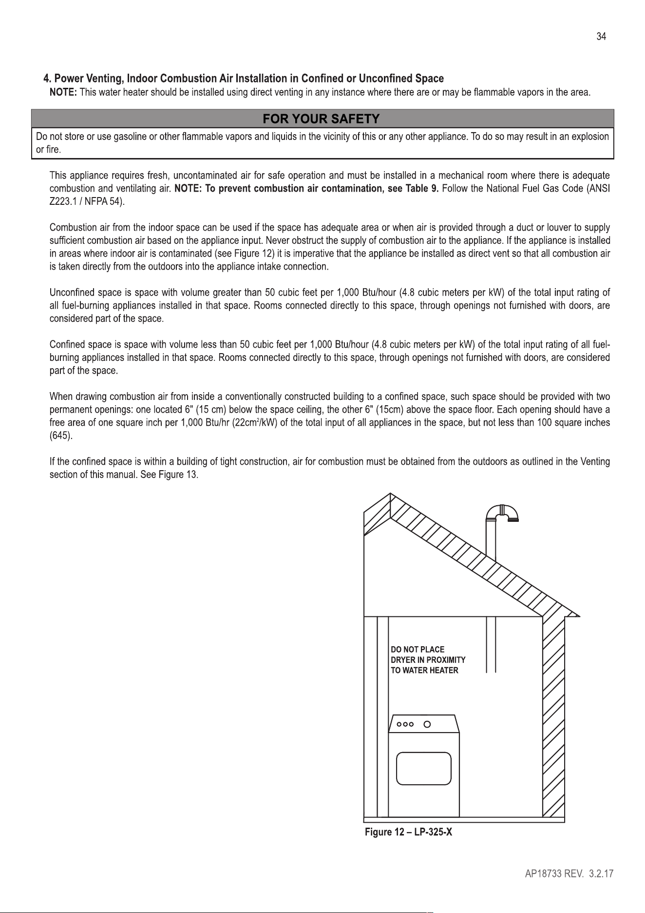
This water heater is not suitable r use in manuctured (mobile) homes.
Printed in the USA.
www.rheem.com
AP18733 REV. 3.2.17
FOR YOUR SAFETY READ BEFORE OPERING
WARNING : If you do not follow these instructions exactly, a fire or explosion may result
causing propey damage, personal injury or loss of life.
A.This appliance does not have a pilot. It is equipped with an ignition device which automatically
lights the burner. Do not t to light the burner by hand.
B.BEFORE OPETING smell all around the appliance area for gas. Be sure to smell next to the
floor because some gas is heavier than air and will settle on the floor.
WHAT TO DO IF YOU SMELL GAS
eDo not try to light any appliance. eDo not touch any electric switch; do not use any phone
in your building. elmmediately call your gas supplier from a neighbor's phone. Fol
i
low the gas
supplier's instructions. e1r you cannot reach your gas supplier, call the fire department.
eoo not return to your home until authorized by the gas supplier or fire depament.
C.Use only your hand to push
in o
r turn the gas control k
n
ob. Never use tools. If the knob will
not push in or turn by hand,don't try to repair it, call a qualified service technician. Force or
attempted repair may result in a fire or explosion.
D.Do not use this appliance if any pa has been under water. Immediately call a qualified
seice technician to inspect the appliance and to
r
eplace any pa of the control svstem and
any gas control which has been under water
.
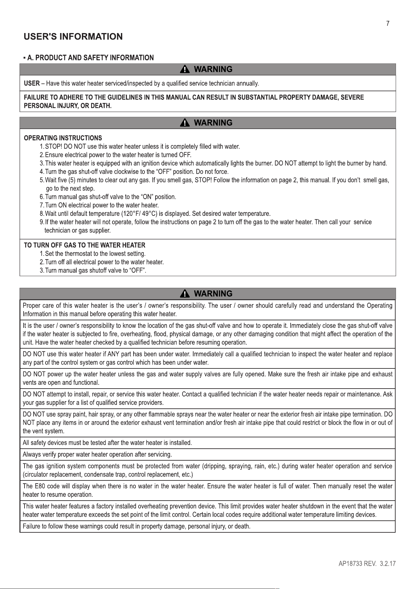
OPERATING INSTRUCTIONS
1.STOP! Read the safety inrmation above on this label.
2.Turn off all electric power to the appliance.
3.Do not attempt to light the burner by hand.
GAS SHUTOFF
LVE
4
.
Turn the Gas Shuto Valve located on the outside of the unit
clockwise " to the "OFF" position.
OPEN CLOSE
5.Wait five (5) minutes to clear out any gas. If you then smell gas, STOP! Follow "B" in
the safety information above on this label. If you don't smell gas, go to the next step.
6.Turn the Gas Shuto Valve located on the outside of the unit counterclockwise 0 to
the "ON" position.
7.Turn on all electric power to the appliance.
8.
l
f the appliance wil
l
not operate, follow the instructions "To Turn O Gas To Appliance"
and call your seice technician or gas supplier.
TO TURN OFF GAS TO APPLIANCE
1.Turn off all electric power to the appliance if service is to be performed.
2.Turn the Gas Shuto Valve located on the outside of the unit clockwise " to the "OFF" position.
DANGER indicates an imminently hazardous situation which, if not avoided, will result in death or serious injury.
A RNING
WARNING indicates a potentially hazardous situation which, if not avoided, could result in death or serious injury.
A CAUTION
CAUTION indicates a potentially hazardous situation which, if not avoided, may result in minor or moderate injury.
IMPORTANT
IMPORTANT is used to indicate a potentially hazardous situation which, if not avoided, may result in property damage, FOR YOUR SAFETY is
used to indicate specific safety related instructions or procedures, and NOTICE is used to address practices not related to personal injury.
NOTE: Contains additional inrmation important to a procedure.
2
AP18733 REV. 3.2.17
3
A WARNING
California Proposition 65 Warning: This product contains chemicals known to the State of California to cause cancer bih defects,
or other reproductive harm.
• FOREWORD
A DANGER
A Vapors from flammable
liquids will explode and
catch fire causing death or
severe burns.
Do not use or store flammable
products such as gasoline,
solvents or adhesives In the
same room or area near t11e
water heater.
Keep flammable products:
1. far away from heater,
2. In approved containers,
3. tightly closed and
4. out or children's reach.
Installation:
Water heater has a main
burner flame.
The main burner flame:
1. which can come on
at any time and
2. wlll Ignite flammable
vapors.
Vapors:
1. cannot be seen,
2. are heavier than air,
3. go a long way on the
floor and
4. can be carried from
other rooms to the
main burner flame by
air currents.
Do not Install water t1eater 18" above the floor. T11ls will
where flammable products will reduce, but not eliminate, the
be stored or used unless the
risk of vapors being Ignited
main burner flame Is at least
by the main burner flame.
Read and 1ollow water heater warnings and Instructions. If
O\'Jners manual Is missing, contact the retailer or manufacturer.
A DANGER
Water temperature over 125 F (52
°
C)
can cause severe burns instantly or
death from scalds.
Children, disabled and elderly are
at highest risk of being scalded.
S instruction manual before
setting temperature at water
heater.
Fl water before bathing or
showering.
Tperature limiting valves are
available, see manual.
This manual is intended to be used in conjunction with other literature provided with the water heater. This includes all related control information.
It is important that this manual, all other documents included with this system, and additional publications including the National Fuel Gas Code,
ANSI 2223.1-2002, be reviewed in their entirety bere beginning any work.
Installation should be made in accordance with the regulations of the Authority Having Jurisdiction, local code authorities, and utility companies
which pertain to this type of water heating equipment.
Authority Having Jurisdiction (AHJ) - The Authority Having Jurisdiction may be a federal, state, local government, or individual such as a
fire chief, fire marshal, chief of a fire prevention bureau, labor department or health department, building oicial or electrical inspector, or others
having statutory authority. In some circumstances, the property owner or his/her agent assumes the role, and at government installations, the
commanding oicer or departmental oicial may be the AHJ.
NOTE: Rheem reserves the right to modi product technical specifications and components without prior notice.
• FOR THE INSLLER
This manual must only be used by a qualified heating installer/service technician. Read all instructions in this manual before installing. Perform
steps in the order given. Failure to comply could result in substantial property damage, severe personal injury, or death.
This appliance must be installed by qualified and licensed personnel. The installer should be guided by the instructions furnished with the water
heater, and with local codes and utility company requirements. In the absence of local codes, prerence should be given to the National Fuel
Gas Code, ANSI 2223.1-2002.
INSTALLATIONS MUST COMPLY WITH:
Local, state, provincial, and national codes, laws, regulations and ordinances.
The latest version of the National Fuel Gas Code, ANSI 2223.1, from American Gas Association Laboratories, 8501 East Pleasant Valley Road,
Cleveland, OH 44131.
In Canada - CGA No. 8149 (latest version), from Canadian Gas Association Laboratories, 55 Scarsdale Road, Don Mills, Ontario, Canada
M38 2R3. Also, Canadian Electrical Code C 22.1, from Canadian Standards Association, 5060 Spectrum Way, Suite 100, Mississauga, Ontario,
Canada L4W 5N6.
Code r the installation of Heat Producing Appliances (latest version), from American Insurance Association, 85 John Street, New rk, NY
11038.
The latest version of the National Electrical Code, NFPA No. 70.
NOTE: The gas manifold and controls met safe lighting and other peormance criteria when the water heater undeent tests specified in ANSI
221. 10.3 - latest edition.
AP18733 REV. 3.2.17

4
BLE OF CONTENTS
USER'S INFORMATION .......................................................................................................................................................... 7
A. PRODUCT AND SAFETY INFORMATION ...................................................................................................................... 7
1. BEFORE OPERATION ................................................................................................................................................. 8
2. DURING OPERATION ................................................................................................................................................. 8
3. TROUBLESHOOTING AND GENERAL CAUTIONARY SEMENTS .................................................................... 9
B. MAINTENANCE ............................................................................................................................................................. 10
1. SEICE TECHNICIAN ............................................................................................................................................. 10
2. OWNER MAINTENANCE .......................................................................................................................................... 10
C. MAINTENANCE PROCEDURES .................................................................................................................................. 10
1. DAI MAINTENANCE .............................................................................................................................................. 10
2. MONTH MAINTENANCE ....................................................................................................................................... 11
3. 6 MONTH MAINTENANCE ........................................................................................................................................ 12
4. ANNUAL MAINTENANCE ......................................................................................................................................... 12
D. TROUBLESHOOTING ................................................................................................................................................... 13
THE FOLLOWING ARE INSTALLATION INSTRUCTIONS FOR THE CONTRACTOR. ...................................................... 14
ITEMS SHIPPED WITH THE ER HEER ..................................................................................................................... 15
SAFETY REGULIONS ....................................................................................................................................................... 15
A. OPERATION AND INSLLION RNINGS .......................................................................................................... 15
B. IMPROPER COMBUSTION ........................................................................................................................................... 16
C. GAS ............................................................................................................................................................................... 16
D. WHEN SERVICING THE ER HEER .................................................................................................................. 17
E. ER CHEMISTRY REQUIREMENTS ....................................................................................................................... 17
F. FREEZE PROTECTION ................................................................................................................................................. 17
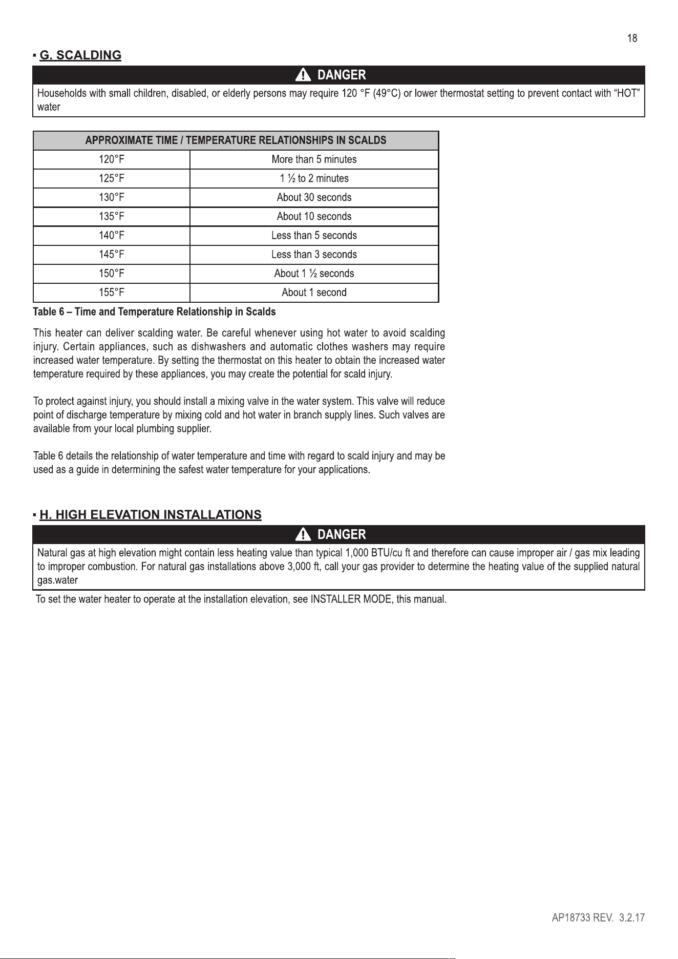
G. SCALDING .................................................................................................................................................................... 18
H. HIGH ELEION INSLLIONS ............................................................................................................................ 18
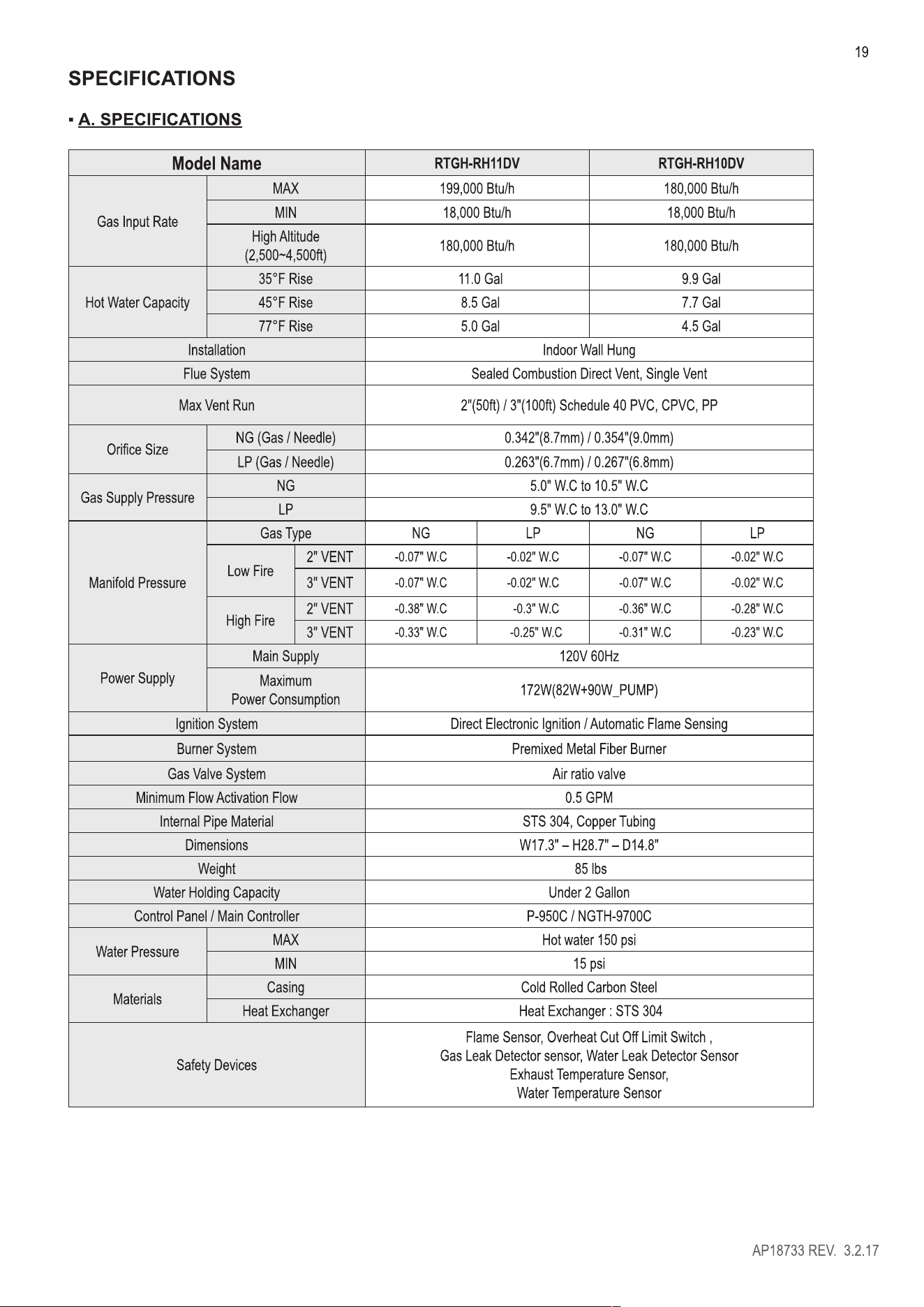
SPECIFICATIONS .................................................................................................................................................................. 19
A. SPECIFICATIONS ......................................................................................................................................................... 19
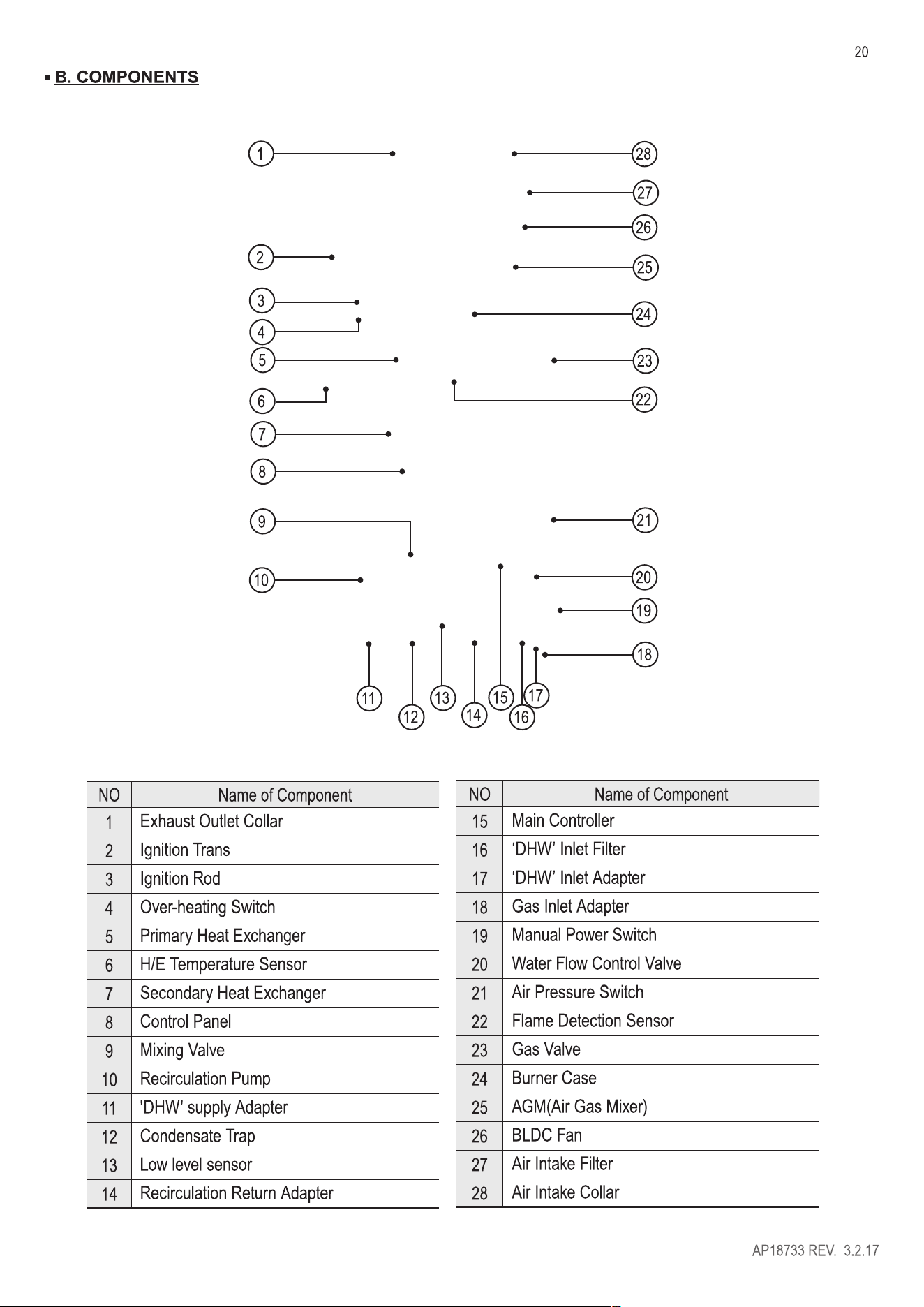
B. COMPONENTS .............................................................................................................................................................. 20
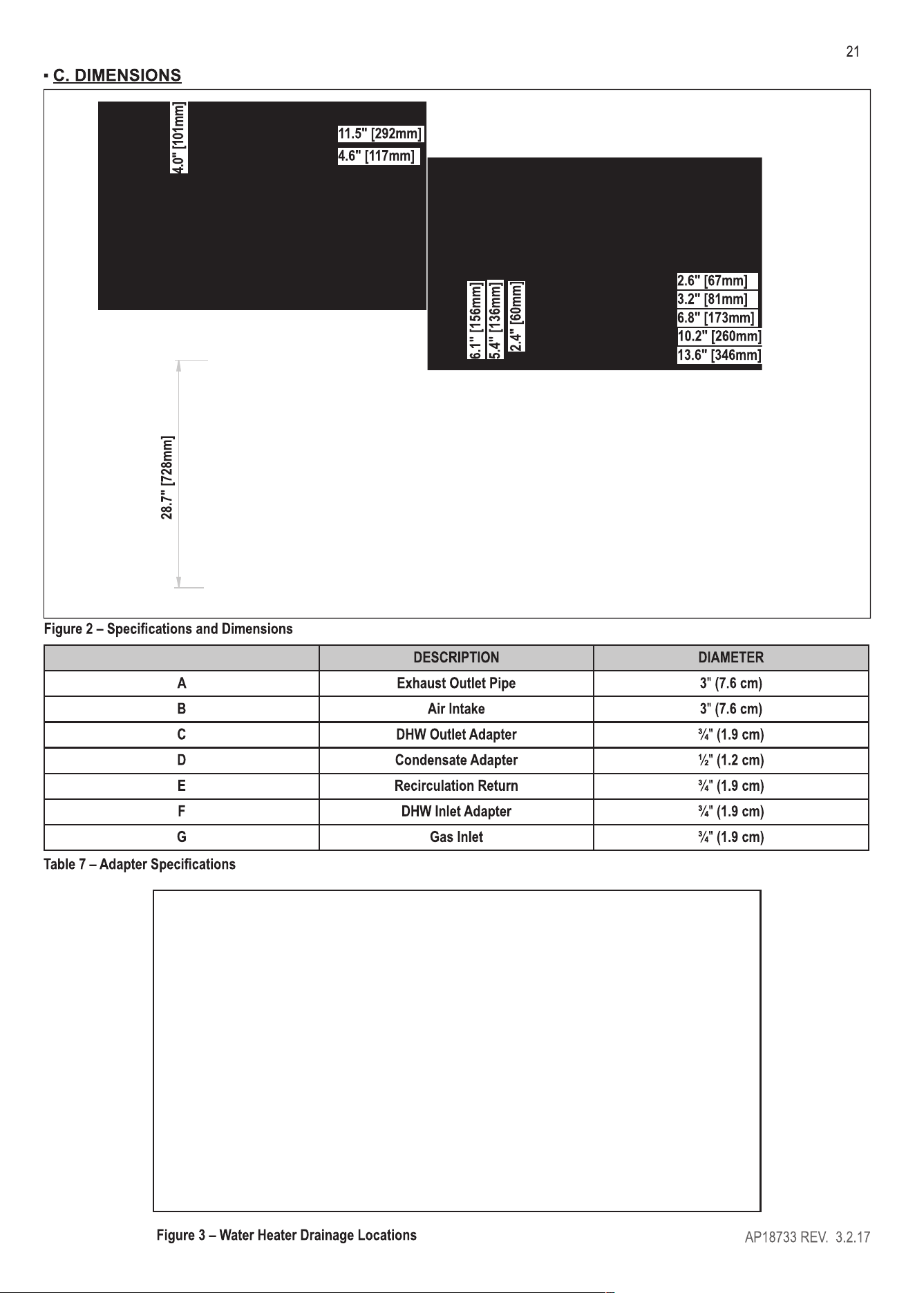
C. DIMENSIONS ................................................................................................................................................................. 21
PRERE ER HEATER LOCION .............................................................................................................................. 22
A. BEFORE LOCING THE ER HEER ............................................................................................................... 22
B. LEVELING ..................................................................................................................................................................... 23
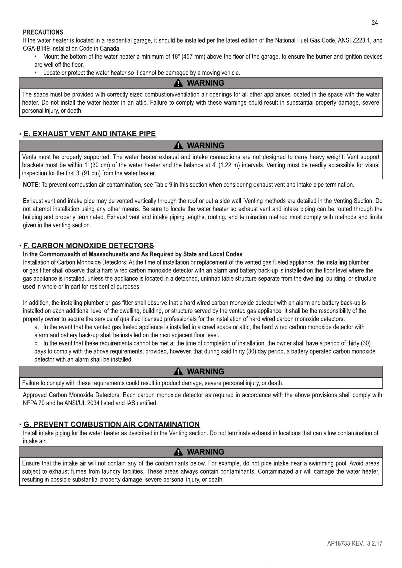
C. CLEARANCES FOR SERVICE ACCESS ..................................................................................................................... 23
D. RESIDENTIAL GARAGE AND CLOSET INSLLIONS ......................................................................................... 23
E. EXHAUST VENT AND INTAKE PIPE ............................................................................................................................ 24
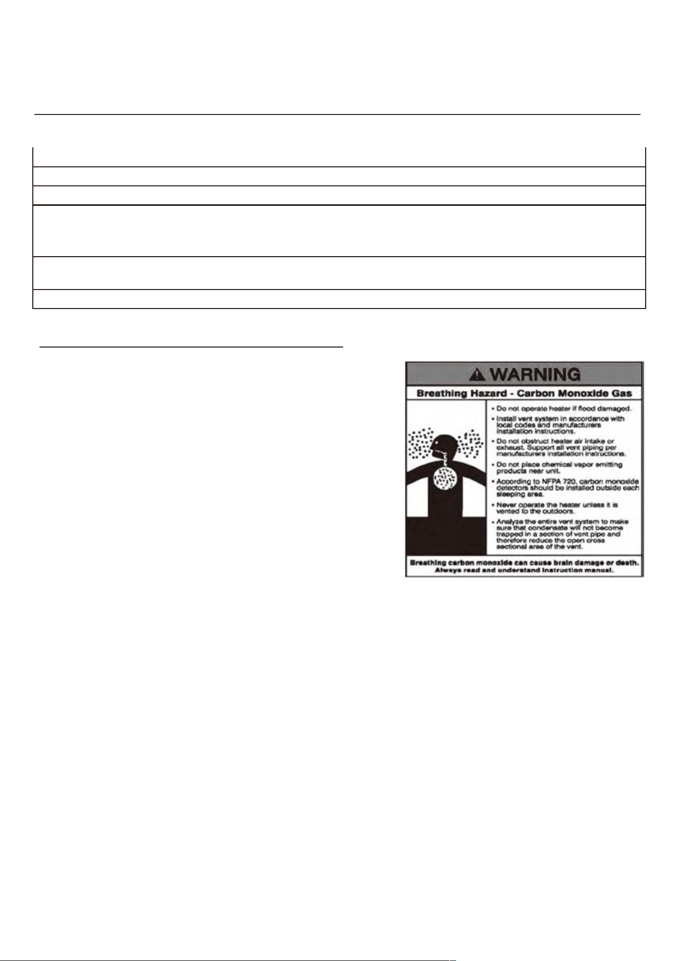
F. CARBON MONOXIDE DETECTORS ............................................................................................................................ 24
G. PREVENT COMBUSTION AIR CONTAMINATION ...................................................................................................... 24
AP18733 REV. 3.2.17

5
H. REMOVING A ER HEATER FROM A COMMON VENT SYSTEM ........................................................................ 25
I. UNPACKING THE WATER HEATER .............................................................................................................................. 25
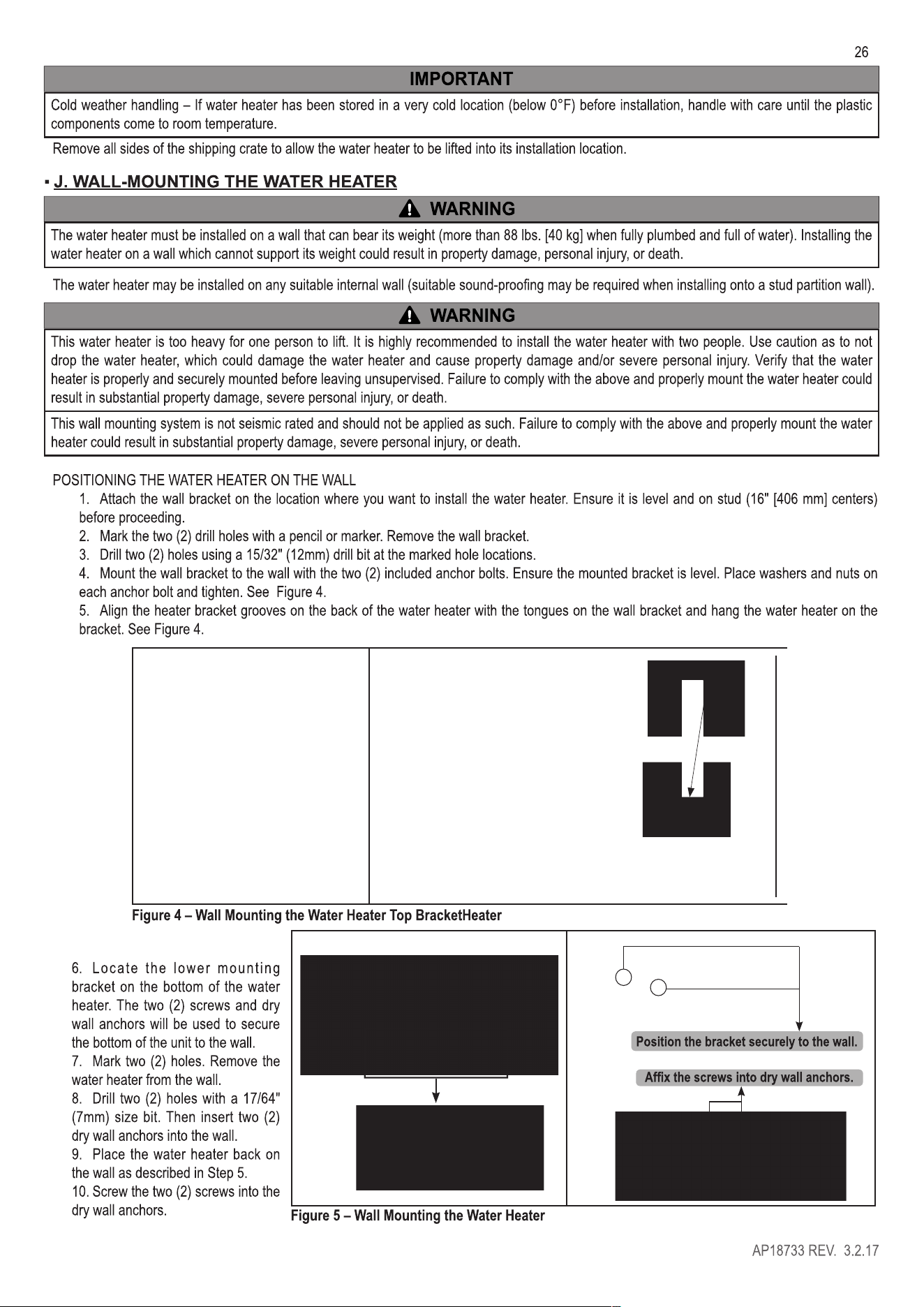
J. LL-MOUNTING THE ER HEER .................................................................................................................... 26
VENTING ................................................................................................................................................................................ 27
A. INKE PIPE AND EXHAUST VENT GUIDELINES ..................................................................................................... 27
B. APPROVED VENT MERIALS ................................................................................................................................... 30
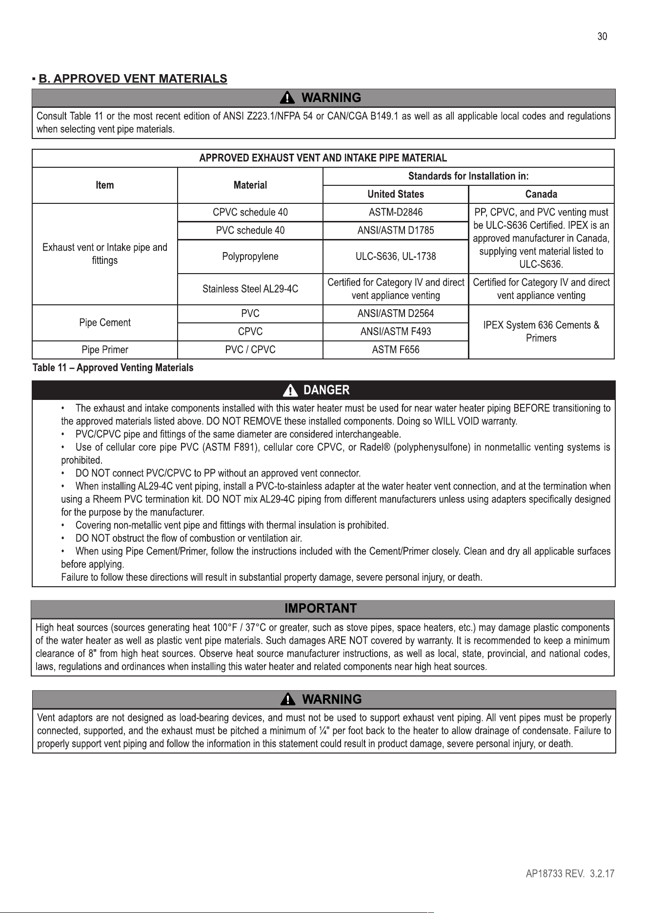
C. ALLOWED SCHEDULE 40 VENT LENGTHS (PVC, CPVC, PP) ................................................................................. 31
D. TIGHTENING ER HEER COLLAR TO EXHAUST VENT AND INKE PIPE ................................................. 31
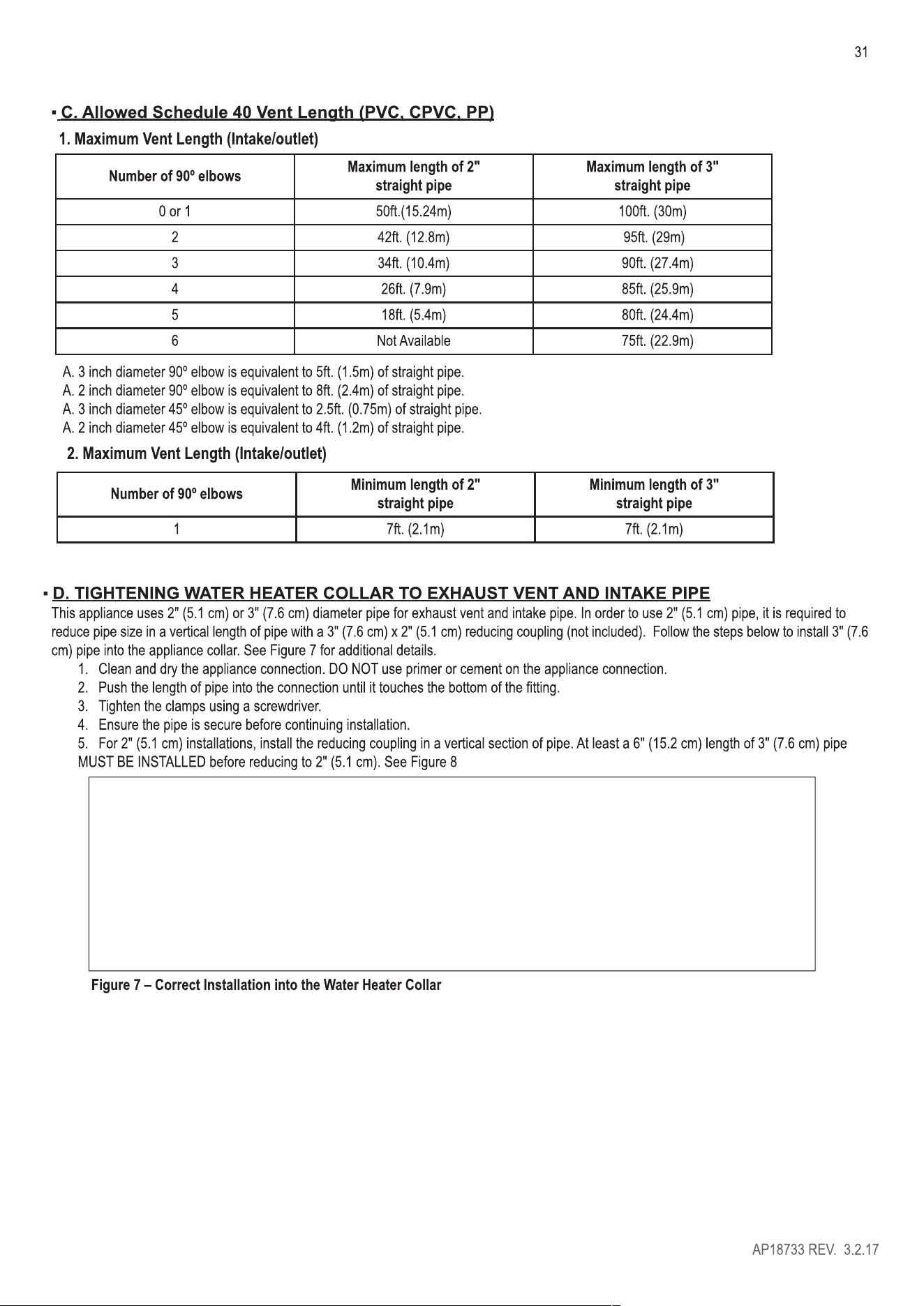
E. VENT TERMINION .................................................................................................................................................... 32
1. Direct Vent, o Pipe Roof and Sidewall nt rminations ............................................................................... 32
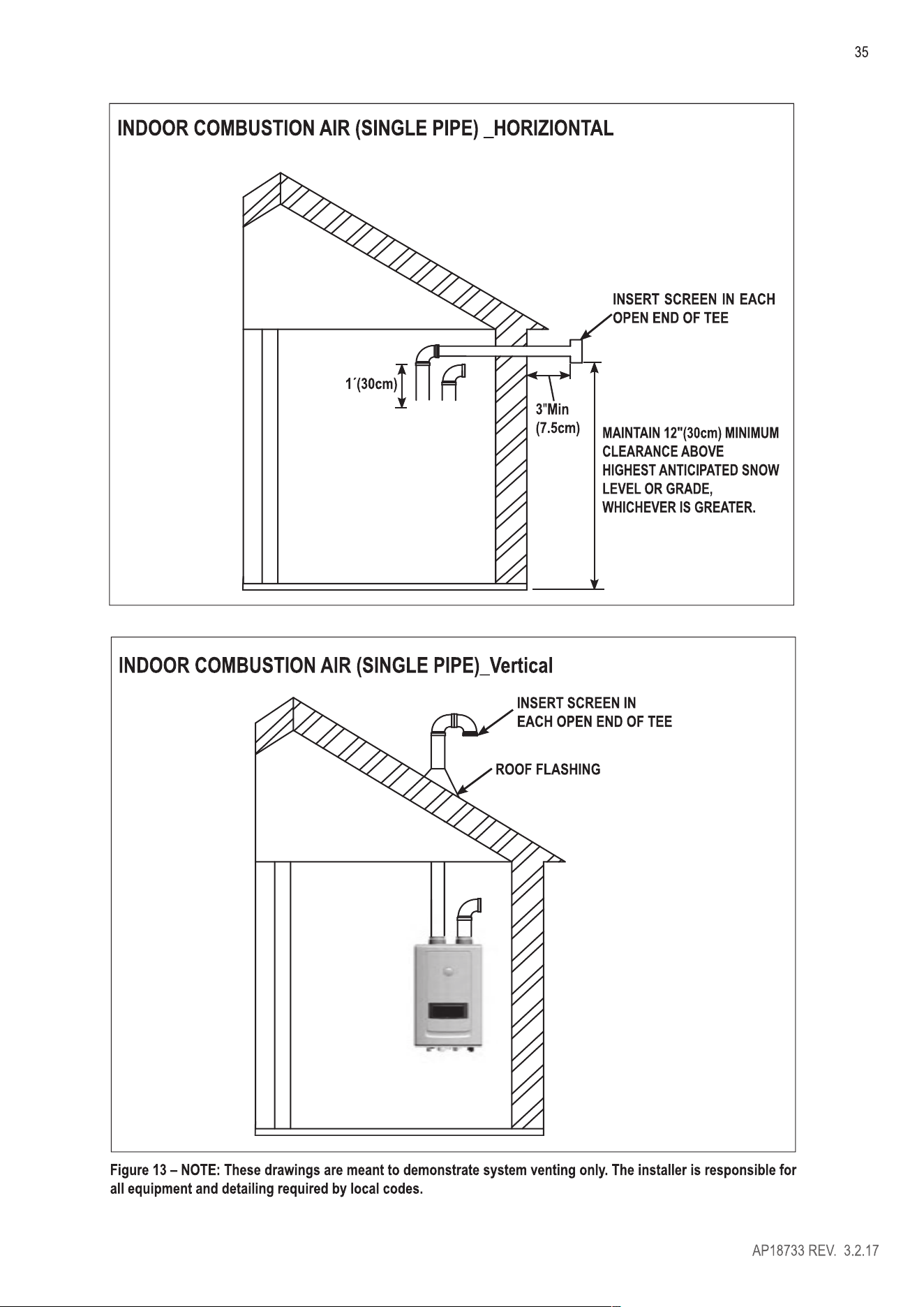
2. Direct nt, Optional Horizontal and rtical Vent Kits ........................................................................................ 32
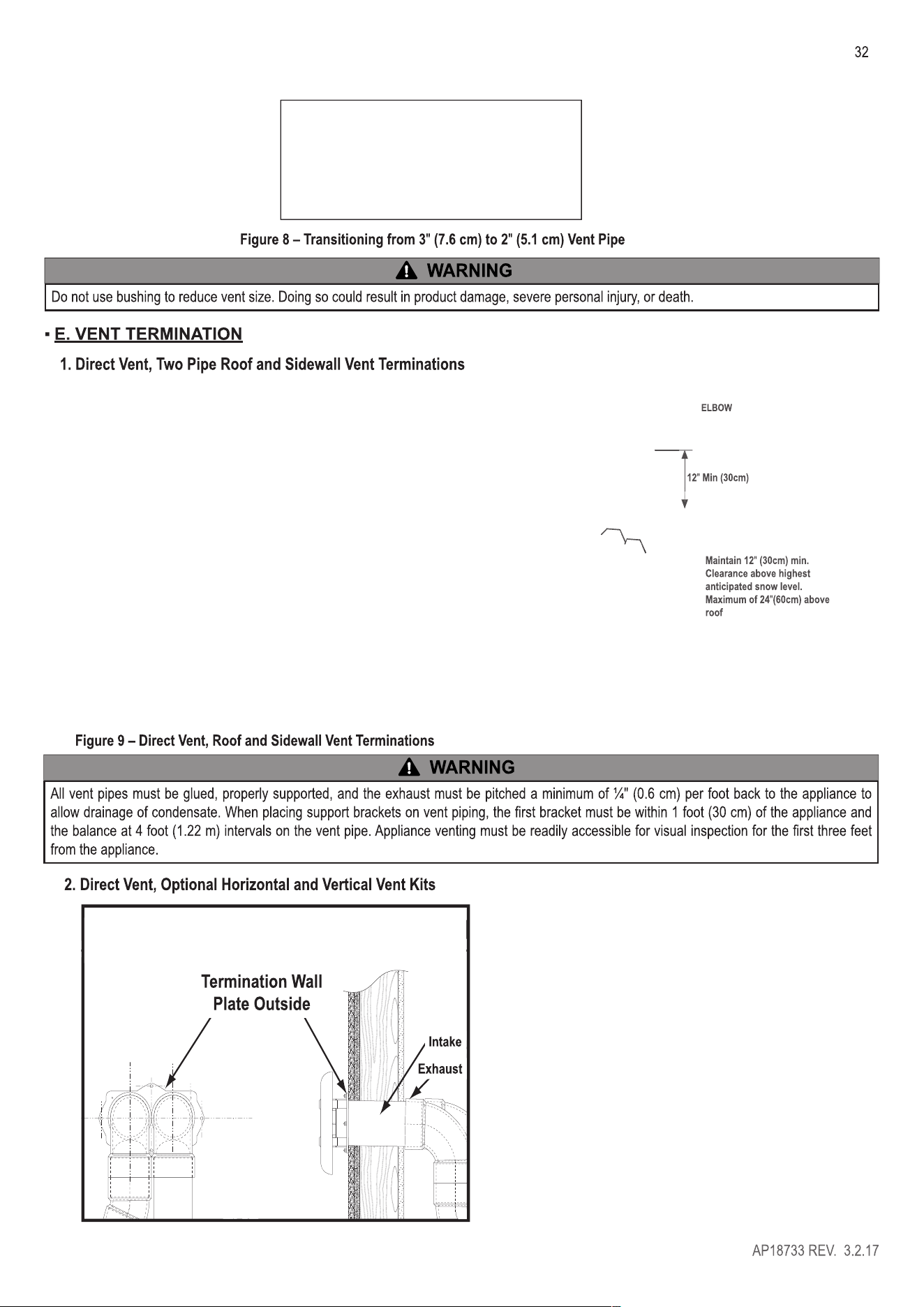
3. Screen lnstallation .................................................................................................................................................... 33
4. Power nting, Indoor Combustion Air Installation in Confined or Unconfined Space .................................... 34
F. COMMON VENT PIPING ................................................................................................................................................ 36
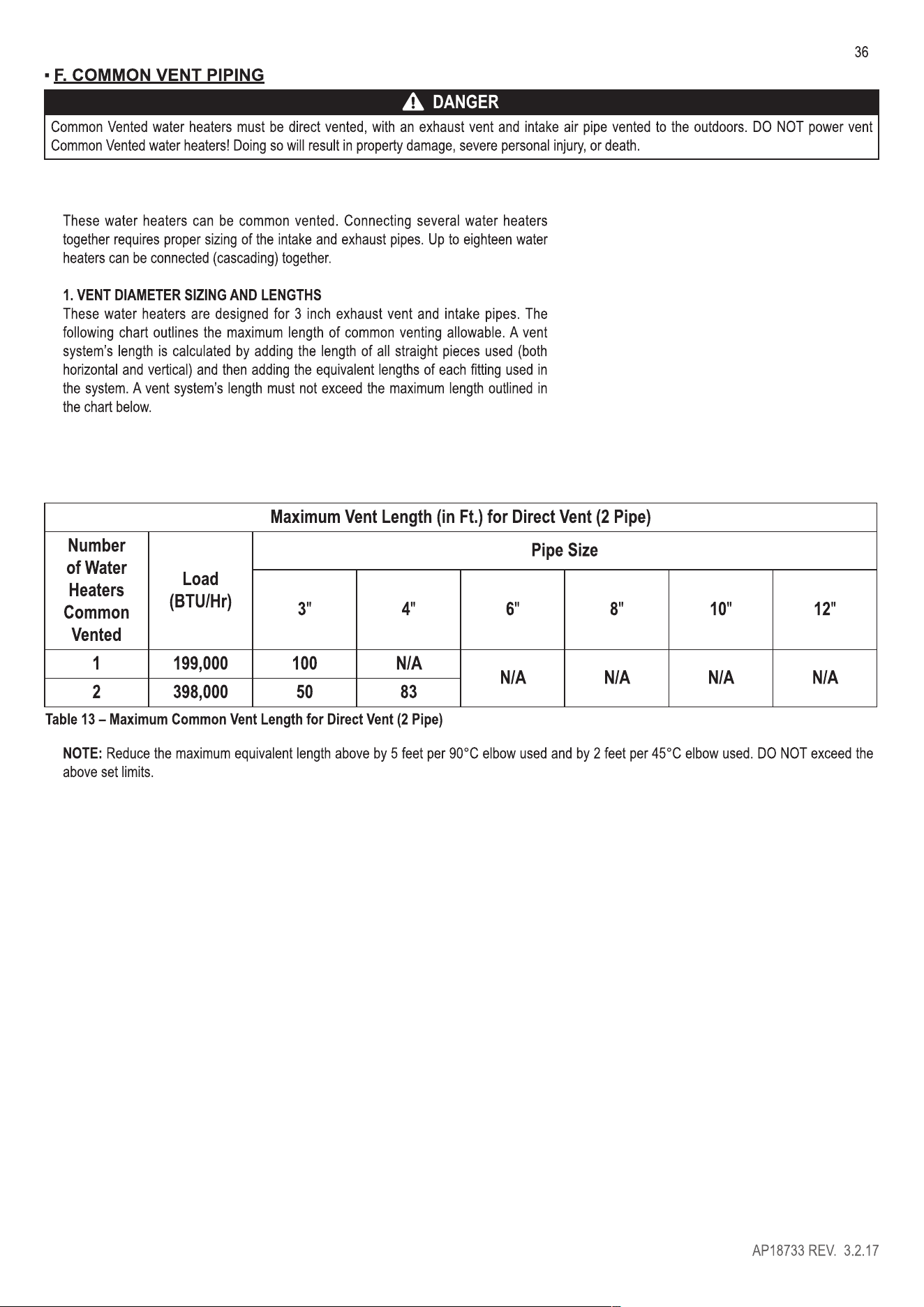
1. VENT DIAMETER SIZING AND LENGTHS .............................................................................................................. 36
2. RECOMMENDED EXHAUST PIPE TRANSITIONS ................................................................................................. 37
3. TWO PIPE VENT SYSTEM (DIRECT VENT) ............................................................................................................ 38
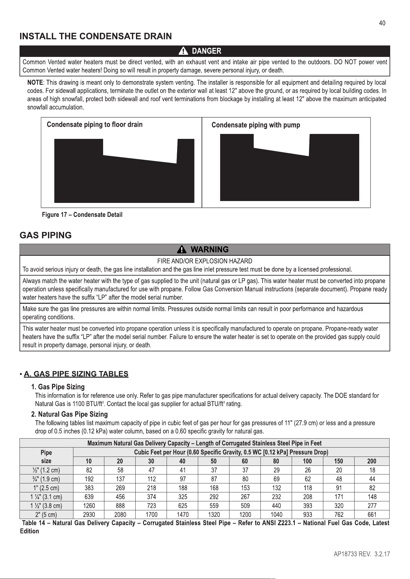
INSLL THE CONDENSE DRAIN .................................................................................................................................. 40
GAS PIPING .......................................................................................................................................................................... 40
A. GAS PIPE SIZING BLES .......................................................................................................................................... 40
1. Gas Pipe Sizing ......................................................................................................................................................... 40
2. Natural Gas Pipe Sizing ........................................................................................................................................... 40
3. LP (Liquid Propane) Gas Pipe Sizing ...................................................................................................................... 41
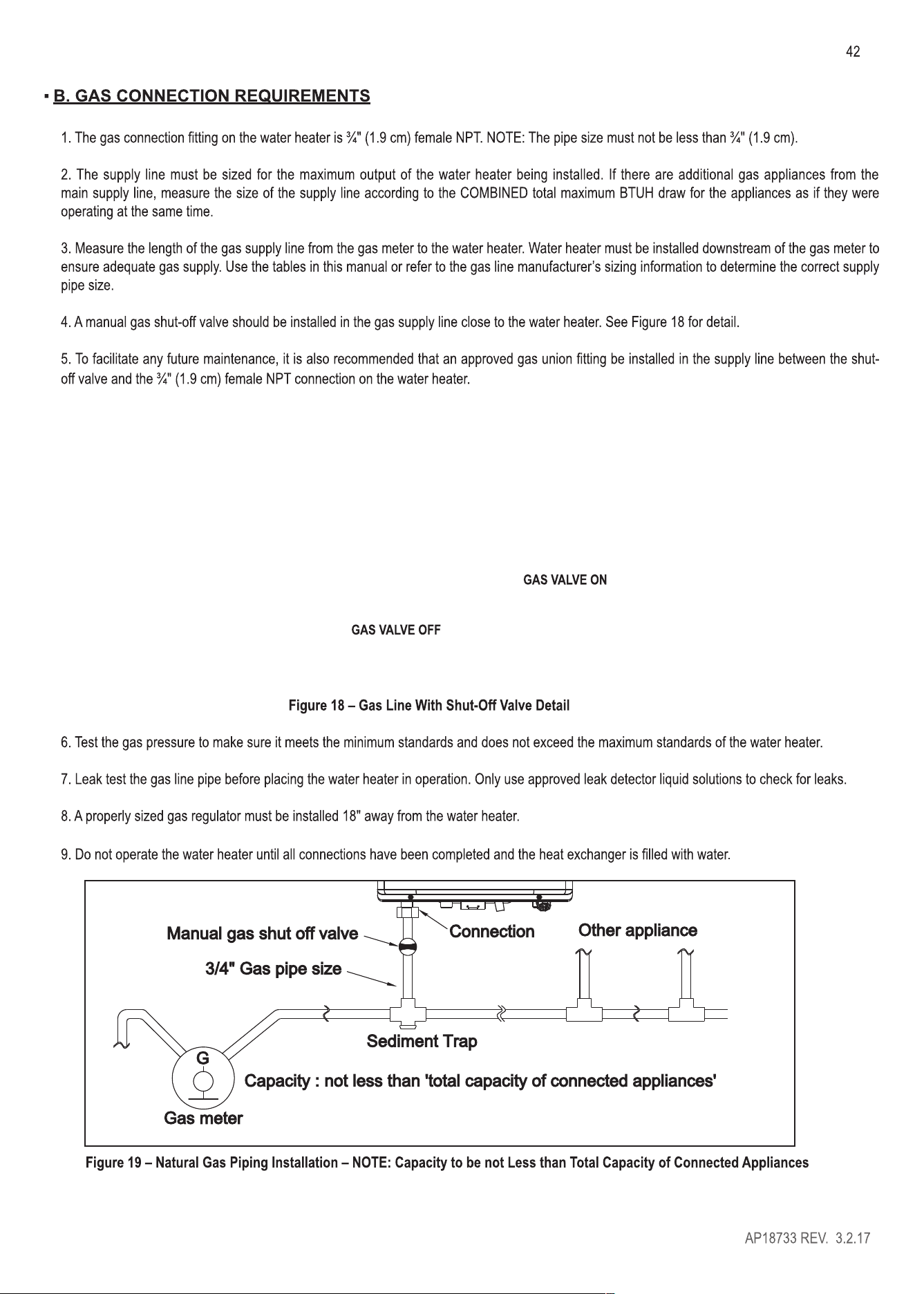
B. GAS CONNECTION REQUIREMENTS ......................................................................................................................... 42
C. ADDITIONAL PRECAUTION FOR EXCESS FLOW VAE (EFV) .............................................................................. 43
D. ADJUSTING GAS PRESSURE THE ER HEATER .......................................................................................... 43
E. SETTING AND VERIFYING THE COMBUSTION SETTING ......................................................................................... 43
ER PIPING ..................................................................................................................................................................... 44
A. GENERAL PLUMBING CONNECTION GUIDELINES ................................................................................................. 44
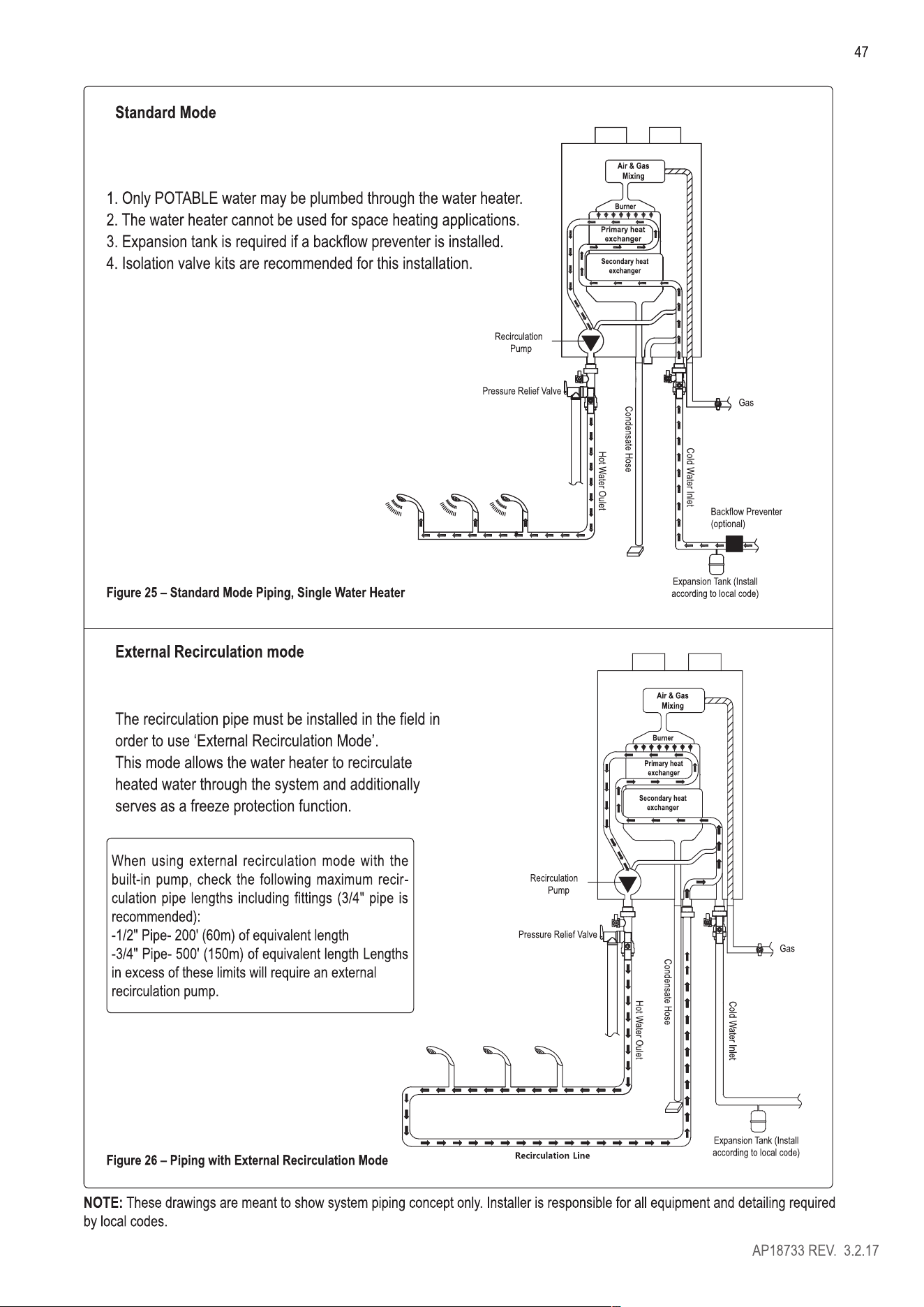
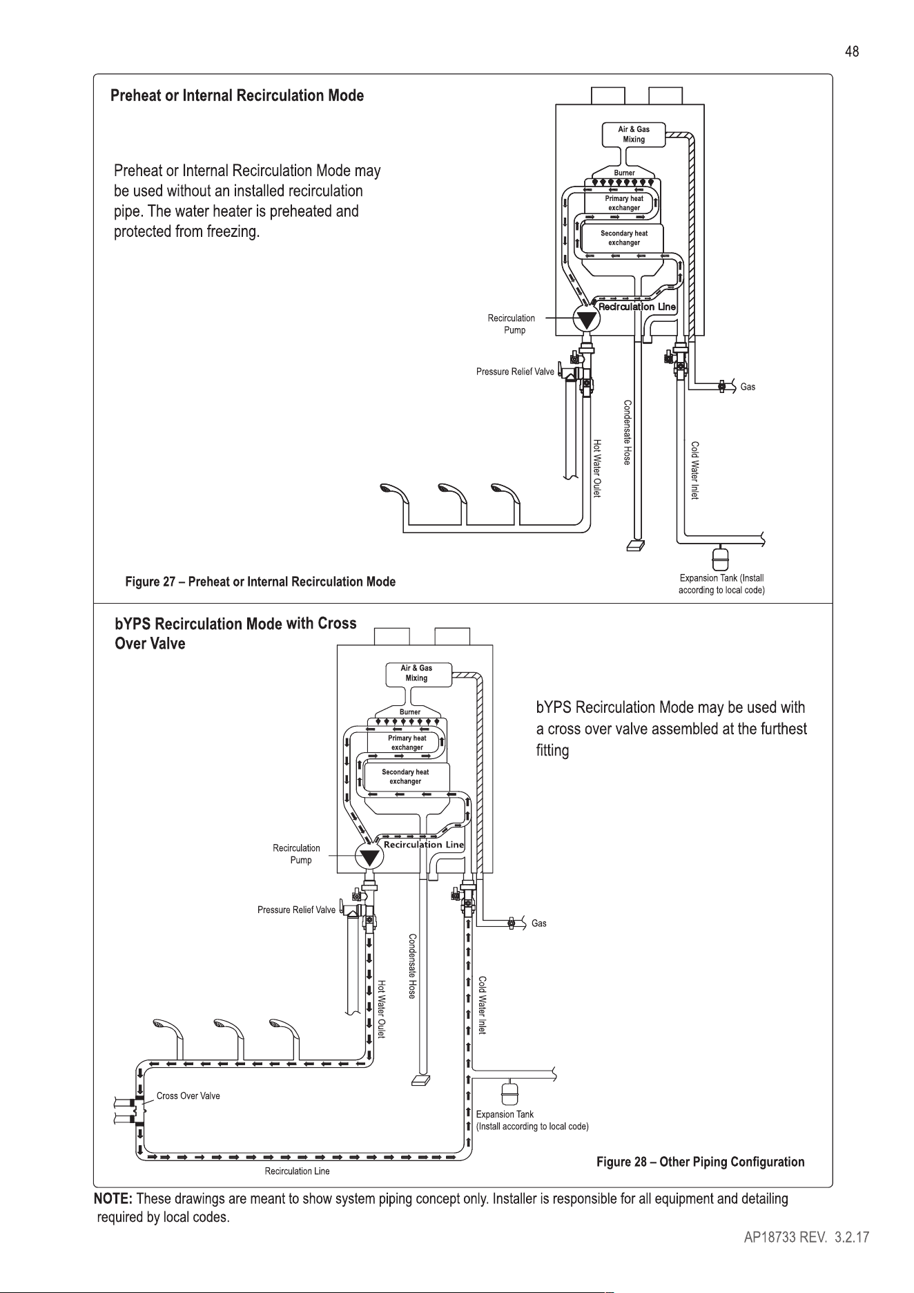
B. INSLL A BACKFLOW PREVENTER ........................................................................................................................ 46
C. PIPING THE ER HEATER ...................................................................................................................................... 46
D. APPLICIONS ............................................................................................................................................................. 46
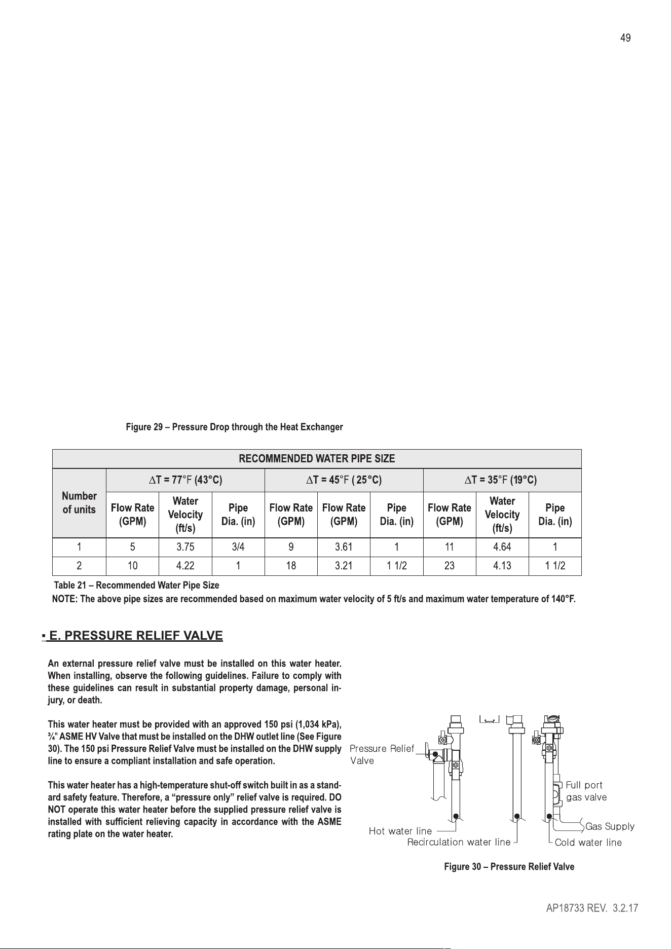
E. PRESSURE RELIEF LVE .......................................................................................................................................... 49
CONNECT ELECTRICAL POWER/ INITIAL STARTUP ....................................................................................................... 50
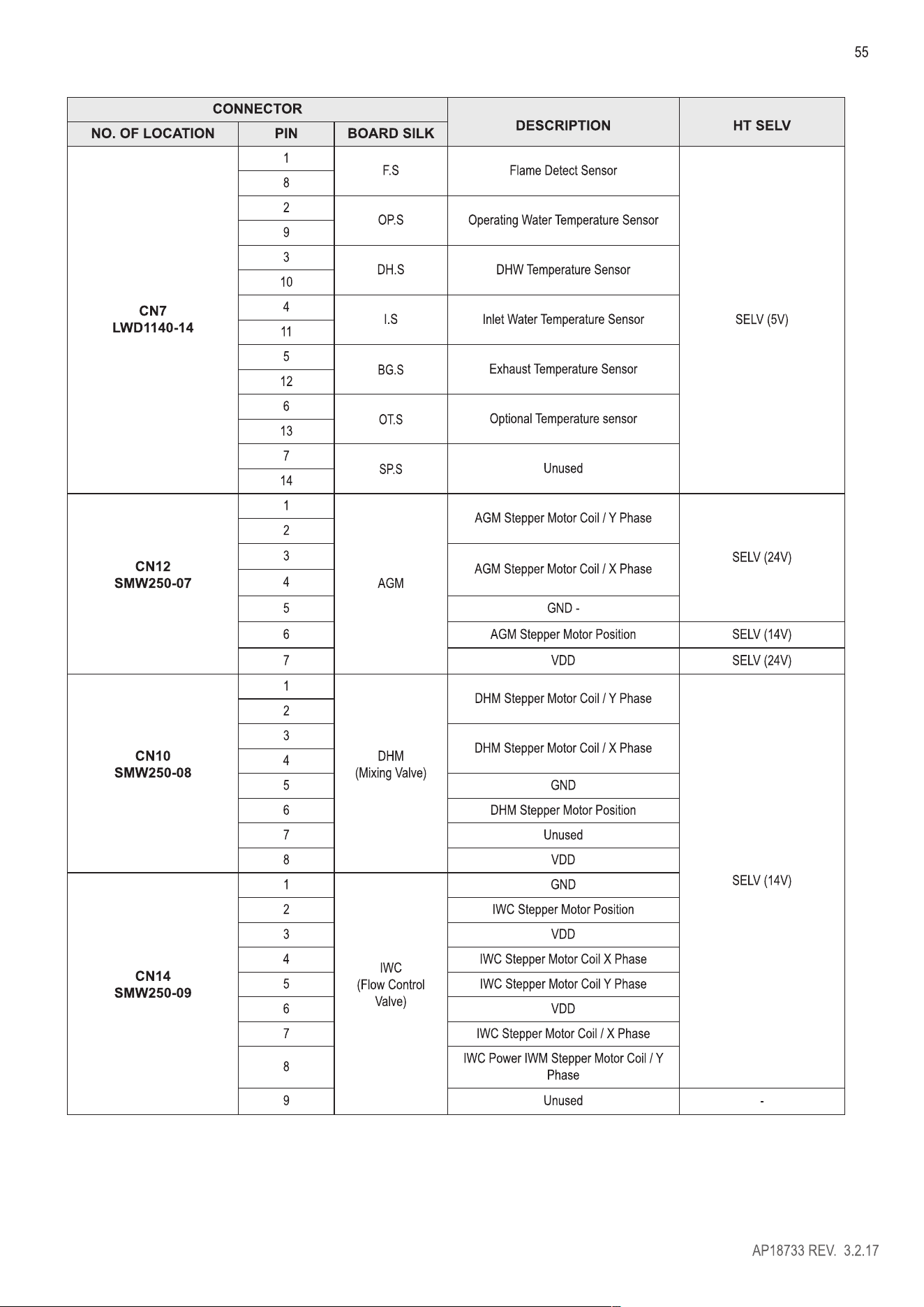
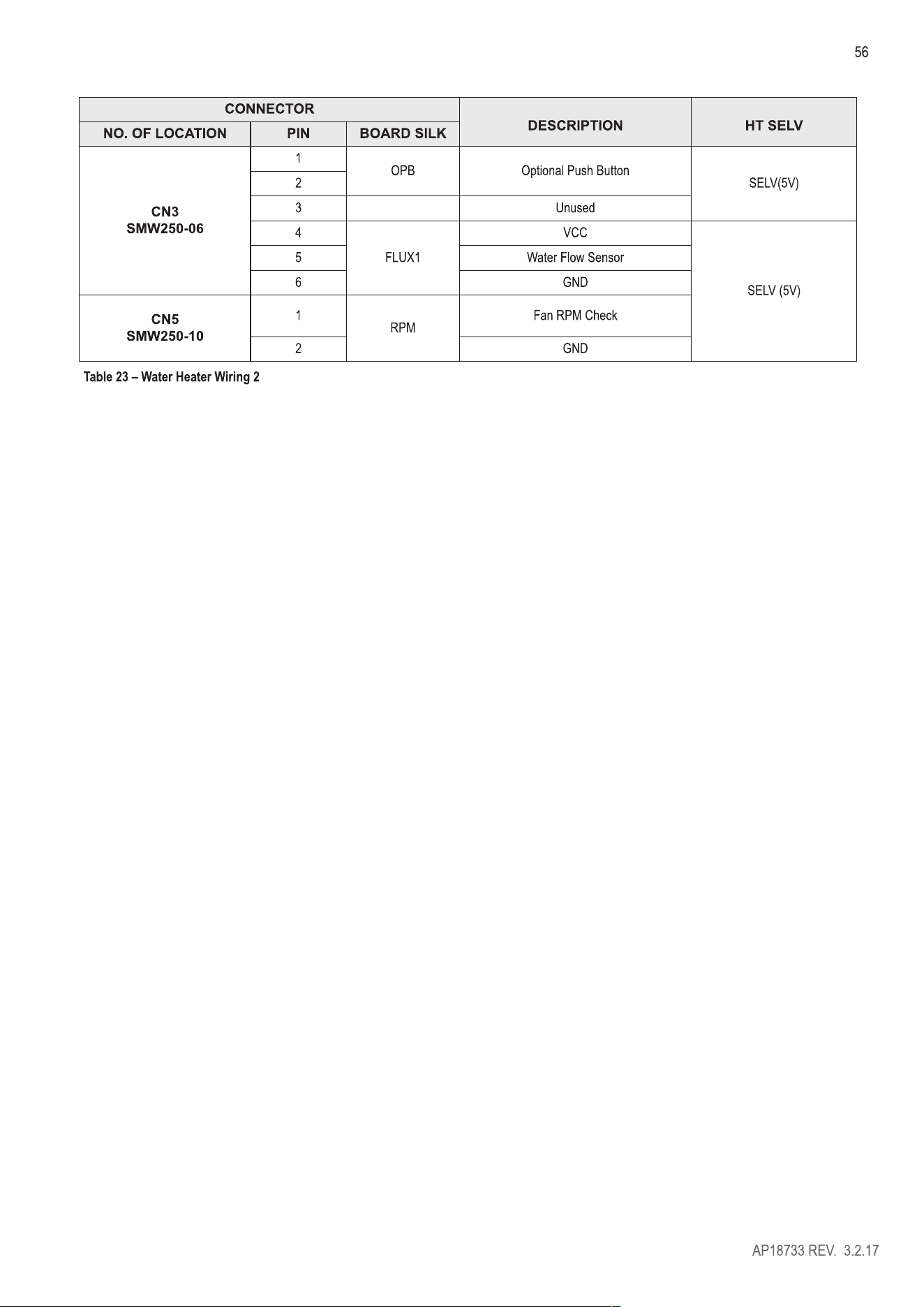
A. WIRING INFORMION ................................................................................................................................................ 50
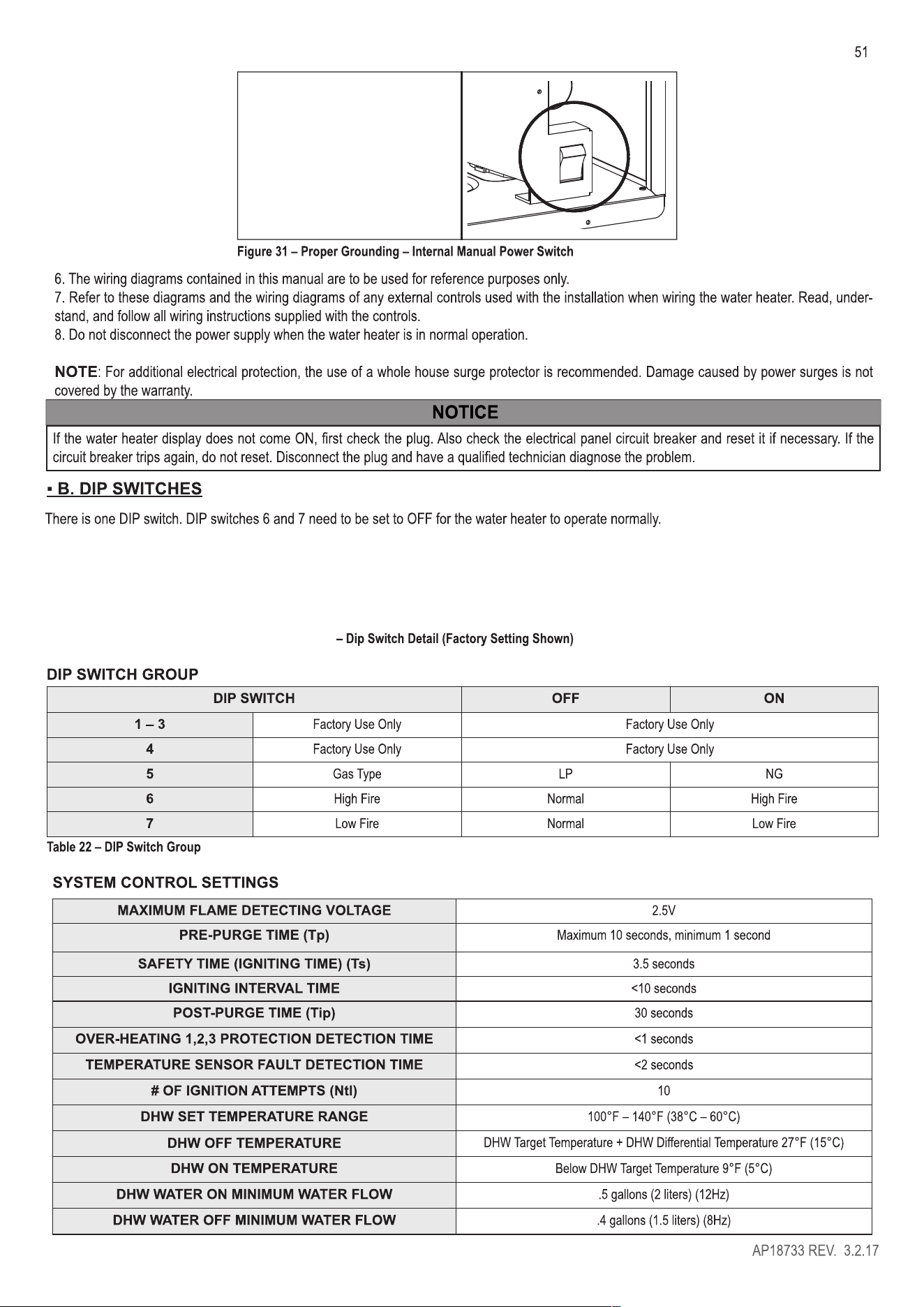
B. DIP SWITCHES .............................................................................................................................................................. 51
AP18733 REV. 3.2.17
27
VENTING
Vent this water heater in accordance with these instructions. Failure to do so will result in property damage, severe personal injury, or death.
DO NOT mix vent systems or materials unless specifically told to do so in this manual.
DO NOT thermally insulate the exhaust vent or intake pipes.
DO NOT use an electric damper, vent damper, or draft hood with this water heater.
DO NOT locate the exhaust vent or intake pipe terminations where exposed to prevailing winds.
Moisture will be produced by the exhaust vent. Take precautions when determining exhaust vent termination. Moisture may fall from the vent
termination to the ground and turn to ice in freezing conditions. Moisture or ice can produce a hazardous condition.
Exhaust condensate is acidic, and could deteriorate the surface below the exhaust vent termination. Ensure this surface is in good repair (sealed,
painted, etc.) to prevent deterioration.
Failure to follow these instructions could result in property damage, severe personal injury, or death.
■ A. INTAKE PIPE AND EXHAUST VENT GUIDELINES
1. Vent system must be installed in accordance with local codes, or, in absence of
local codes, the National Fuel Gas Code, ANSI Z223.1 I NFPA 54 and/or CSA B 149.1,
Natural Gas and Propane Installation Code.
2. For installation in Canada, installer supplied plastic vent piping must comply with
CAN/CGA B149.1 and be certified to the Standard for Type BH Gas Venting Systems,
ULC-S636. Components of this listed system must not be interchanged with other vent
systems or unlisted pipes or fittings. All plastic components and specified primers and
glues must be from a single system manufacturer and must not be intermixed with
another system manufacturer's products. Clean and dry all applicable surfaces before
applying cement.
3. This water heater is designed to be installed in as a direct vent (sealed combustion)
type. In direct vent installations, combustion air must be supplied directly from the
outdoors to the burner, and the flue (exhaust) gases should be vented directly to the
outdoors through the wall or roof.
4. This water heater uses 2" (5.1 cm) or 3" (7.6 cm) diameter pipe for exhaust vent and
intake pipe. It is important to ensure an airtight seal from the water heater collar to the vent terminations. It is EXTREMELY IMPORTANT that the
maximum allowed combined venting lengths are not exceeded. See Table 11 for a list of Approved Vent Materials and Table 12 for Approved Vent
Lengths.
5. Do not install venting system components on the exterior of the building except as specifically required by these instructions.
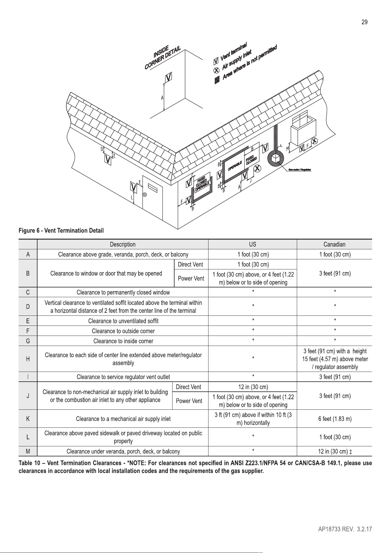
• Vent terminals must be at least 1 foot (30 cm) from any door, window, or gravity inlet into the building.
• Maintain the correct clearance and orientation between the exhaust vent and intake pipe terminals.
• The exhaust vent and air intake terminals must be at the same height and their center lines must be spaced apart 1 foot (30 cm) minimum.
• The bottom of the exhaust vent and intake pipe terminals must be at least 1 foot (30 cm) above the normal snow accumulation level. In no
case should these terminals be installed less than 1 foot (30 cm) above normal snow accumulation level.
• If installing exhaust vent terminals directly above windows or doors, allow at least 1 foot (30 cm) of clearance from top of opening.
• Intake pipe terminal must not terminate in areas that might contain combustion air contaminates, such as near swimming pools.
• For sidewall venting, the minimum horizontal distance between adjacent exhaust vent terminations is 1 foot (30 cm). It is recommended this
distance be greater than 1 foot (30 cm) to better avoid frost damage to building surfaces.
• For roof venting, minimum horizontal distance between any adjacent exhaust vent termination is 1 foot (30 cm).
• If the exhaust vent is to be terminated in a walled o area (such as a roof with a parapet wall), ensure the exhaust vent terminates a
minimum of 1 O' (3m) from nearest wall and extends level with or above the top of the wall. This will ensure flue gas does not get trapped
and possibly recirculated into the intake air pipe, which could contaminate the combustion air.
AP18733 REV. 3.2.17

LP GAS TANK
Figure 20 - LP Gas Piping Installation - NOTE: Capacity to be Not Less than tal Capacity of Connected Appliances
■ C. ADDITIONAL PRECAUTION FOR EXCESS FLOW LVE (EFV)
If an excess flow valve (EFV) is in the gas line, check the manufacturer's minimum and
maximum flow capacity ratings. An improperly sized EFV will not allow for a full flow of gas
to the water heater and will cause the water heater to malfunction. See Figure 21.
NOMINAL CLOSURE
FLOW RATE (SCFH): 335
MAXIMUM LOAD
43
CAPACI (BTU/HR) 275,000
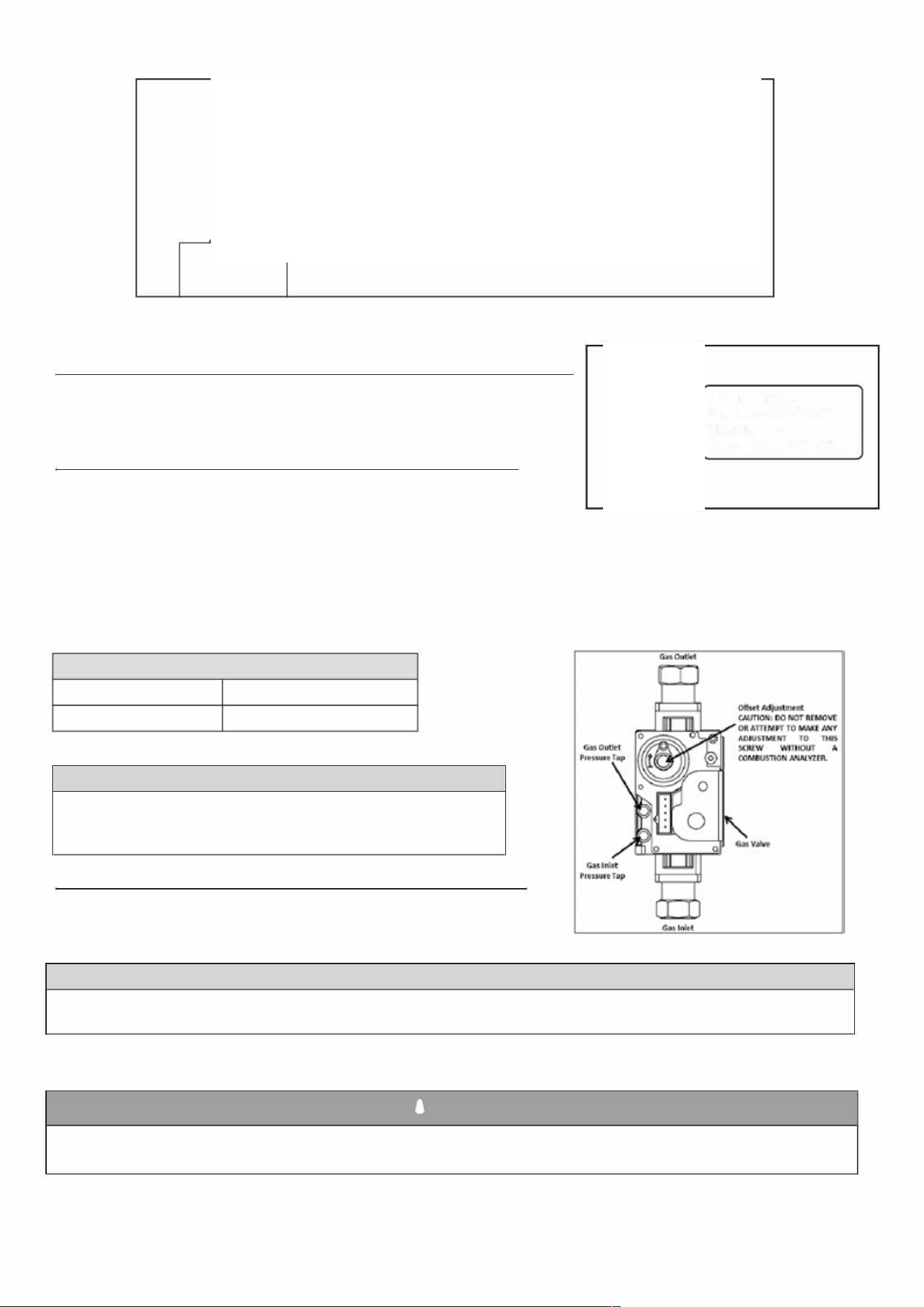
• D. ADJUSTING GAS PRESSURE THE ER HEATER
NOTE: Refer Figure 22 when adjusting gas pressure. Loosen the bolts bere checking the
gas inlet pressure.
Figure 21 - Excess Flow Valve (EFV)
1. The water heater and its individual shuto valve must be disconnected from the gas
supply piping system during any pressure testing of the system at test pressures greater
than ½ psi (3.5 kPa).
2. The water heater must be isolated from the gas supply piping system by closing its individual manual shuto valve during any pressure testing of
the gas supply piping system at test pressures equal to or less than ½ psi (3.5 kPa). The minimum and maximum inlet gas line pressures must meet
the requirements shown in ble 18.
LP GAS / NURAL GAS
Minimum Pressure
5.0" W.C (1.25 kPa)
Maximum Pressure
13.0" W.C (3.24 kPa)
Table 18 - Gas Pressure Requirements
NOTICE
Do not fire (operate) the water heater until all connections have been complet
ed and the heat exchanger is filled with water. Doing so will damage the water
heater and void the warranty.
■ E. SETTING AND VERIFYING THE COMBUSTION SETTING
NOTE: Turn on a hot water faucet at a nearby location in the water heating system to
draw water at a high flow rate. This will ensure the water heater will run continuously
while running the combustion test.
NOTICE
Figure 22 - Inlet Gas Pressure Port Detail
Do not fire (operate) the water heater until all connections have been completed and the heat exchanger is filled with water. Doing so will
damage the water heater and void the warranty.
1. Aer the appliance has fired, flip DIP switch seven (7) to the ON position (low fire). Proceed to check appliance combustion values.
NOTE: Use a combustion analyzer to ensure CO and CO2 values are within the range shown in ble 19.
A WARNING
It is required to use a combustion analyzer to verify final adjustment according to the combustion chart (Table 19). Failure to do so could
result in serious personal injury or death.
AP18733 REV. 3.2.17
44
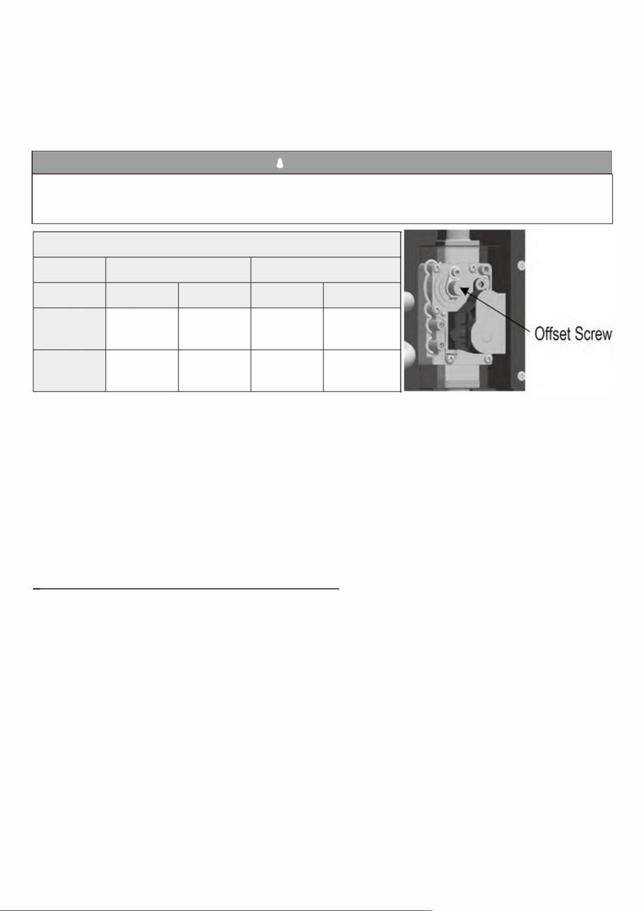
If the readings obtained are lower or higher than the combustion readings in ble 19, use a T15 Torx key to adjust the oset screw in a
clockwise (positive) or counterclockwise (negative) direction (approximately 1/4 turn). See Figure 23. Check your combustion values. Repeat
this procedure until the values obtained on the combustion analyzer agree with those stated in ble 18.
NOTE: If the appliance makes a whistling sound (harmonics) at low fire, adjust the oset screw in a clockwise (positive) direction
(approximately 1/8 turn). Check your combustion values and ensure they agree with those stated in ble 19 before proceeding.
A WARNING
It is very important that this conversion be set within the recommended CO measurements listed in ble 19. Visually looking at the burner does
not determine combustion quality. Failure to measure combustion with a Combustion Analyzer and set the throttle within the recommended CO
measurements could result in property damage, severe personal injury, or death.
COMBUSTION SETTINGS
NURAL GAS
LP GAS
FAN SPEED
LOW
HIGH
LOW
HIGH
CO PPM
<60 <200 <60 <200
CO2(%)
8 -10
8 ½-10 ½
9-10 ½
9½-10½
ble 19-Combustion Settings
Figure 23 - Gas Valve Oset Screw
2. When low fire settings have been obtained, flip DIP switch seven (7) to its original (OFF) position.
This will return the appliance to normal mode.
3. Flip DIP switch six (6) to ON (high fire). Again check combustion readings with a combustion analyzer.
4. When complete, flip DIP switch six (6) to its original (OFF) position. This will return the appliance to normal mode.
Shut off water at hot water faucet.
5. Allow appliance to operate normally. Ensure it is operating properly.
6. Reinstall the appliance front cover.
ER PIPING
■ A. GENERAL PLUMBING CONNECTION GUIDELINES
• Pipe material must be suitable to meet local codes and industry standards.
Do not use lead, PVC, iron, or any piping which has been treated with chromates, boiler seal, or other chemicals.
• Pipe runs should be kept as short as possible to keep heat loss at a minimum.
• The pipe must be cleaned and without blemish before any connections are made.
• Do not apply a torch within 12" (30 cm) of the bottom connections of the water heater. Doing so could damage the water heater.
Such damages ARE NOT covered by product warranty.
• The size of the hot water pipe should be¾" (1.9 cm) diameter.
• Isolation (shutoff valves) are included and should be used to ease future servicing.
• All piping should be insulated.
• Ensure water pressure to the unit is within 14 (96 kPa) to 70 psi (483 kPa). If water pressure is too low or high, the water heater will not be
able to perform to its full capacity and could be damaged. Such damages are not covered by product warranty.
• If the unit is installed on an upper level to supply water to the levels below, ensure the water pressure to the unit does not fall below 29 psi
(200 kPa). It may be necessary to install a pump system to ensure that the water pressure is maintained at this level.
• If feed water pressure is too high take measures to prevent water hammer (such as installing a pressure regulating valve).
• If this water heater will be installed in an application where the supply water is hard, the water must be treated with a water soener.
Water soeners may be regulated by the local codes. Consult with the Authority Having Jurisdiction for codes, sizing,
and installation guidelines.
AP18733 REV. 3.2.17
AP18733 REV. 3.2.17
59
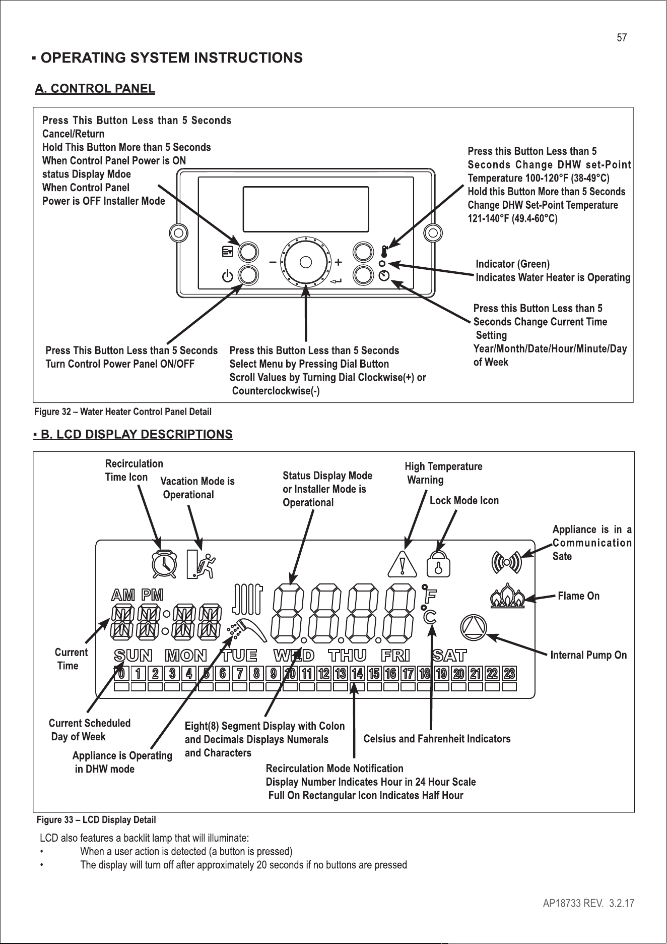
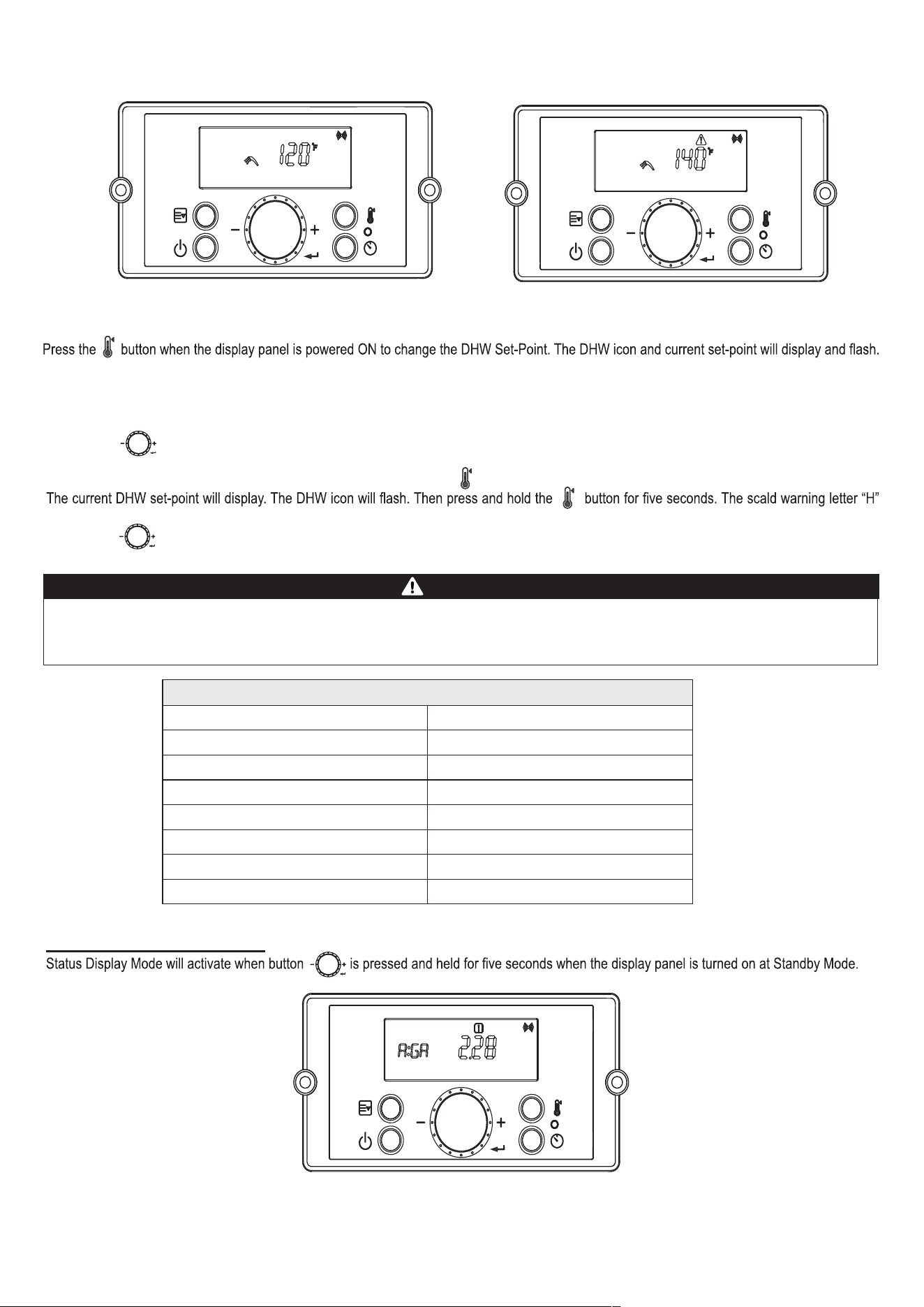
Figure 35 – DHW Set-Point Screens
This indicates that the DHW Set-Point can be changed. Factory DHW Set-Point is 120°F(49°C). Initial DHW Set-Point range is 100 – 140°F (38 –
60°C).
The recommended starting temperature is 120 °F (49°C).
Turn the dial counterclockwise to lower and clockwise to raise the DHW set-point. After changing the temperature, press the button to save
the set-point.
To change the DHW Set-Point above 121°F (49.5°C), press and hold the button when the display panel is powered ON.
(High Temperature Warning icon) will display. High temperature DHW Set-Point range is 121°F – 140°F (49.5°C – 60°C).
Turn the dial counterclockwise to lower and clockwise to raise the DHW set-point. After changing the temperature, press the button to save
the set-point.
Hotter water increases the risk of scald injury. Scalding may occur within 5 seconds at a setting of 140°F (60°C). Water temperature over 125°F
can instantly cause severe burns, or death, from scalds. Children, disabled, and elderly are at the highest risk of being scalded. See instruction
manual before setting temperature at appliance. Feel water before bathing or showering!
DANGER
APPROXIMATE TIME / TEMPERATURE RELATIONSHIPS IN SCALDS
120°F More than 5 minutes
125°F
1 ½ to 2 minutes
130°F
About 30 seconds
135°F
About 10 seconds
140°F
Less than 5 seconds
145°F
Less than 3 seconds
150°F
About 1 ½ seconds
155°F
About 1 second
E. STATUS DISPLAY MODE
Figure 36 – Status Mode Screens
AP18733 REV. 3.2.17
60
Parameter Detail Description
A:Li or GA Flow Unit
Current Flow Unit
(Li: Liters/min, GA: Gallons/min)
b:Fr
Fan Speed (RPM) Current Fan Speed RPM Value
C:Lc Lock Mode
Lock Mode is In Use (ON) or Unused (OFF)
Allows user to lock out any temperature change.
d:Op
Operating Temperature Current Heat Exchanger Operating Temperature
E:dH
DHW Outlet Temperature Current DHW Outlet Temperature
F:Eh
Exhaust Temperature Current Exhaust Temperature
H:In
Inlet Water Temperature Current Inlet Water Temperature
I:rt
PH
Power On Time Power On Time: 1,000 hour increments
rH
Burner Operating Time Burner Operating Time: 1,000 hour increments
bnCY
Burner Cycles Burner Cycles: 1,000 times unit displayed
PPHr
Pump Running Time 1,000 hour increments
J:AG
AGM Adjusts AGM Position: + / - 50
K:TA
Time Adjustment Current Clock Setting
Table 25 – Status Mode Display Screen Descriptions – NOTE: Shaded Parameters Not Used on This Software Version
Turn the dial counterclockwise and clockwise to scroll through the displayed parameters. To view parameter details, press the button at
the appropriate screen. Press the or buttons to leave the parameter.
Press the button again to return to Operation Mode.
To turn on Lock Mode, press the button at the C: Lc parameter. Turn the dial counterclockwise and clockwise to scroll On or Off.
Press the button to save the selection and return to the parameters.
Press the button again to return to Operation Mode.
NOTE: The Control System will not allow the changes if Lock Mode is activated. Lock Mode will have to be turned off before making further
changes
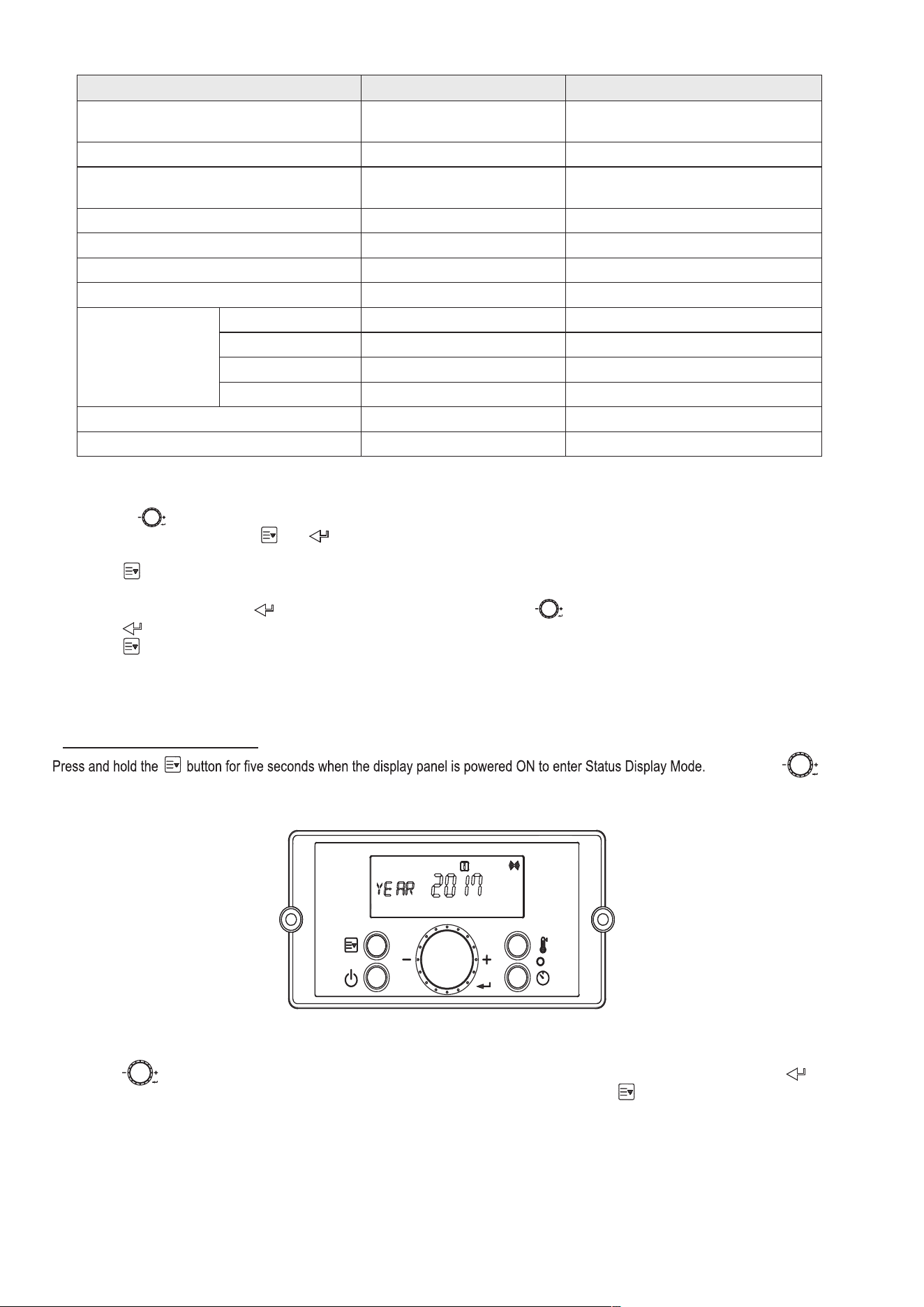
▪ F. CHANGING THE TIME
Turn the dial
counterclockwise and clockwise to scroll through the displayed parameters to parameter K:TA Press the button to enter and change the time.
The time can be adjusted as follows: Year / Month / Date / Hour / Minute / Day of Week.
Figure 37 – Changing the Time Screen
Turn the dial counterclockwise to lower and clockwise to raise the current time setting. After changing the setting, press the button to
save it. The next adjustable setting will appear. After the time settings have been entered, press the button to save and return to the Status
Display screens.
AP18733 REV. 3.2.17
61
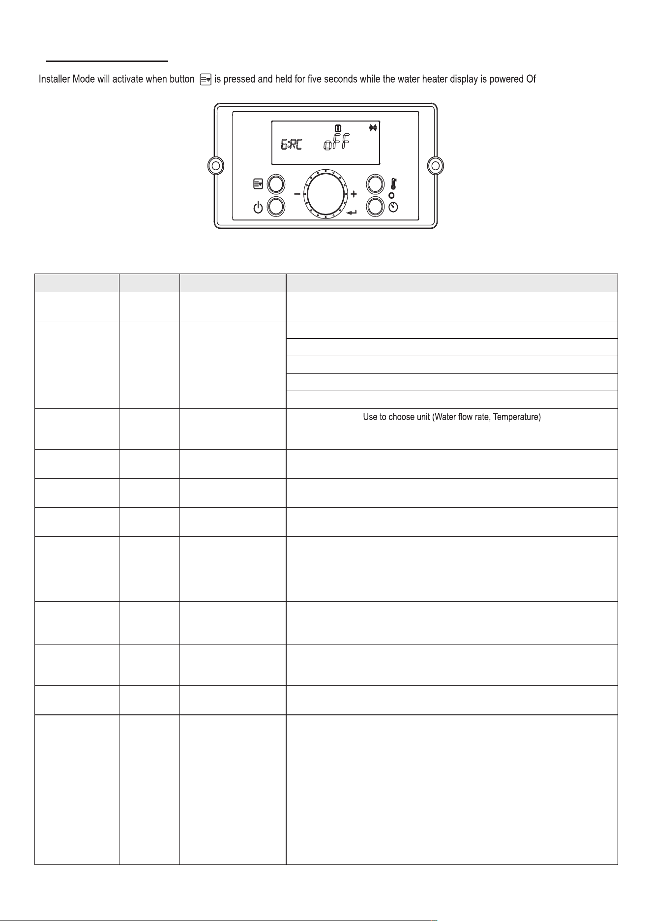
▪ G. INSTALLER MODE
f.
Figure 38– Installer Mode Screens
Index Default Parameter Description
1:EH N/A Error History
Allows the Installer to View the Unit Error History
Range: E0:XX – E9:XX
2:CE
Clear Error & System
initialize
EHIS :Error History
rH : Burn Hour
bnCY : Burn Cycle
PPHr : Pump Running Time
In: System initialize
3:FC GA Unit LIt
℃
: Liter/minute, Celsius
GAL °F : Gallon/minute, Fahrenheit
4:FH 00 Maximum Fan Speed
Adjusts Maximum Fan Speed
Range: -30 - +30
5:FL 00 Minimum Fan Speed
Adjusts Minimum Fan Speed
Range: -30 -+30
6:RC oFF
Recirculation Pump
Operation
Turns the Recirculation Pump On and Off
Range: On – Pump On, oFF – Pump Off
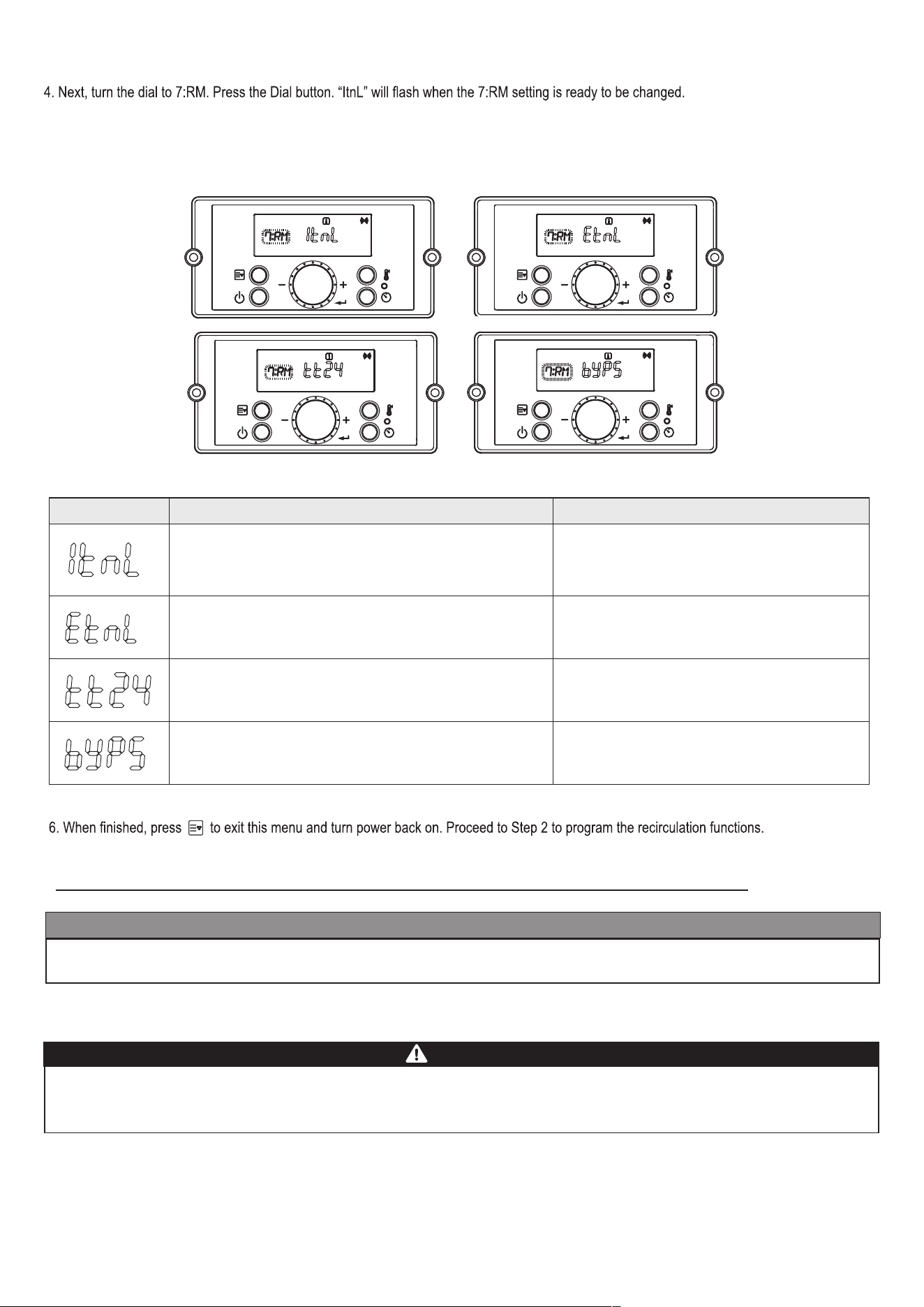
7:RM Itnl Recirculation Mode
NOTE: 6:RC must be set to On to select 7:RM
Sets the Recirculation Mode
Range: ItnL – Internal Recirculation
EtnL – External Recirculation / On Demand Kit,
tt24 – Tilte 24 Mode, bYPS-Cross over
8:RT HI-2 Recirculation Temperature
Sets Recirculation Temperature
Range: LO – Low Temperature, HI-1 – Middle Temperature,
HI-2 – High Temperature
9:HT HI-2 Hot Water Temperature
Sets Hot Water Temperature
Range: LO – Low Temperature, HI-1 – Middle Temperature,
HI-2 – High Temperature
10:IV 6 Prevent Ignition
Temporarily disables the water heater from igniting for a set period of time.
Range: 0 – 20 Minutes
11:HA 0 - 2 High Elevation Mode
This water heater may be installed at elevations up to 10,000 feet and operate on either
Natural or LP. The appliance will de-rate by 4% for each 1,000 feet above sea level.
Select the appropriate installation location as described below.
Selects Installation Location for Proper Water Heater Operation at Altitude:
0-2 for installation locations from sea level to 2,000 feet
2-5 for locations from 2,000 to 5,000 feet
5-8 for locations from 5,000 to 8,000 feet
Default: 0 – 2
NOTE: Use a combustion analyzer to ensure CO and
CO
2
are within the ranges shown in
this manual. Adjust the offset screw in the clockwise (positive) or counterclockwise
(negative) directions (approximately 1/8 turn) if the measured
CO
2
value on LOW FIRE
is out of range.
AP18733 REV. 3.2.17
62
Index Default Parameter Description
12:Cn oFF Cascade
Enables Cascade Mode on the water heater.
Range: on – Cascade is used, oFF – Cascade is not used
13:Eh on Common Vent
NOTE: 12:Cn must be set to On to select 13:Eh
Enables Common Venting on the water heater.
Range: on – Common Venting is used,
oFF – Common Venting is not used
14:T1 oFF Test Mode 1
Used to test the water heater when operating in Internal Recirculation Mode only.
The water heater may operate while Test Mode 2 is operating.
Range: on, oFF
15:T2 oFF Test Mode 2
Used to purge air from the water heating system with an external recirculation pump.
The water heater does not need to operate while Test Mode 2 is operating.
Range: on, oFF
Table 26 – Installer Mode Descriptions
Toggle through displayed items by turning the dial .
To change an item, press the Dial button
.
Displayed items can be changed by turning the dial counterclockwise to lower, and clockwise to raise, the displayed value.
To save settings, press the Dial button again.
To leave Installer Mode, press button again. The water heater will return to power off mode.
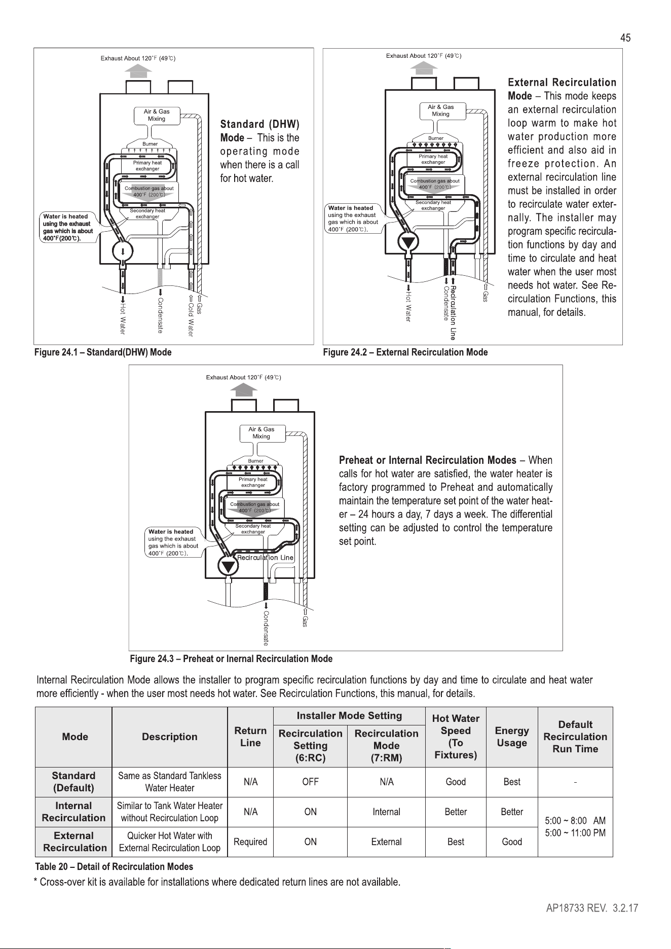
▪ H. USING RECIRCULATION MODES – STEP 1
The following section explains and details the use of the Internal / External Recirculation Modes.
Preheat or Internal Recirculation Modes -
tomatically maintain the temperature set point of the water heater – 24 hours a day, 7 days a week. The differential setting can be adjusted to
control the temperature set point.
-
ciently - when the user most needs hot water. See Recirculation Functions, this manual, for details.
External Recirculation Mode
-
circulation functions by day and time to circulate and heat water when the user most needs hot water. See Recirculation Functions, this manual,
for details.
To set Recirculation Modes:
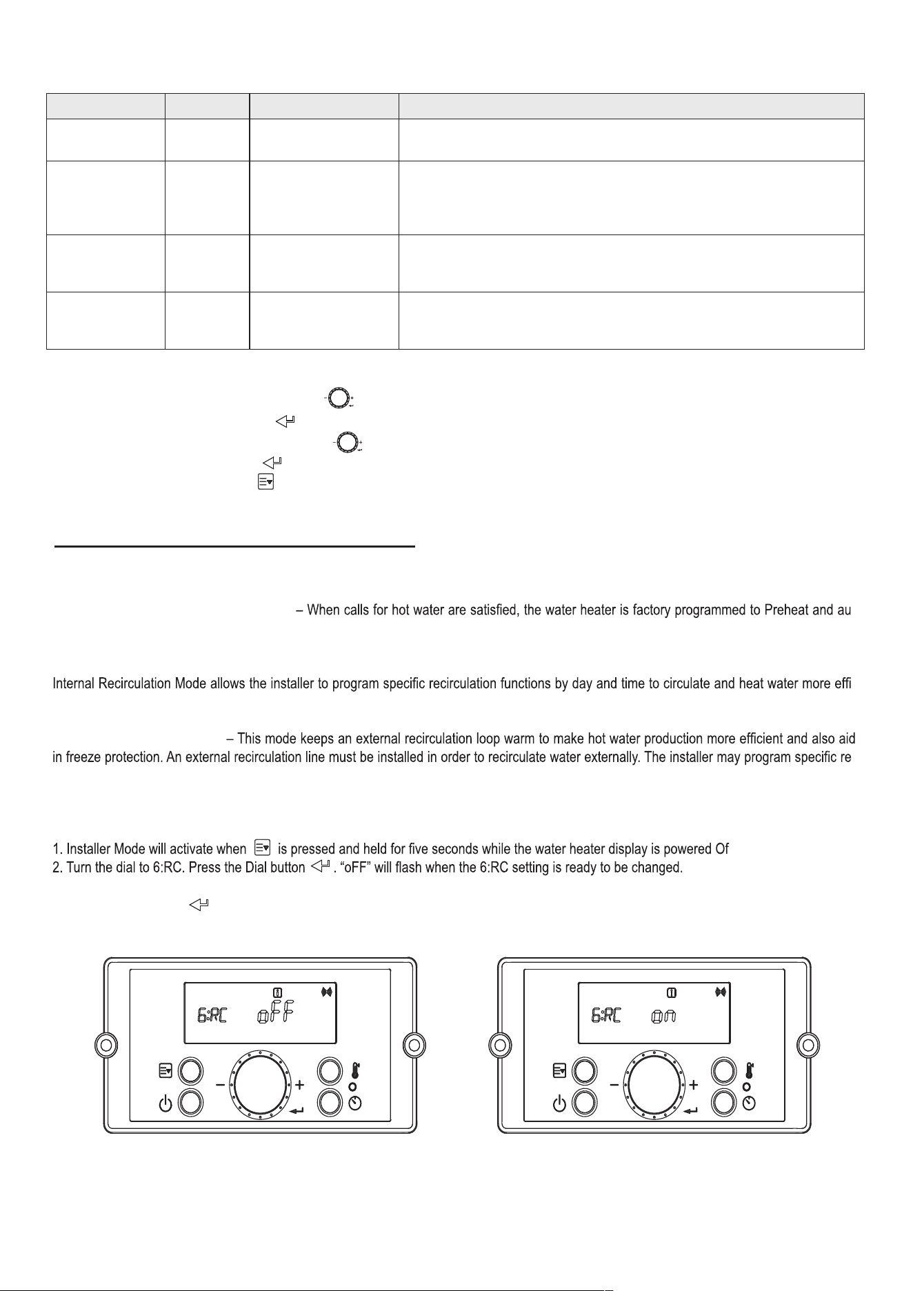
f.
3. Turn the dial to “oFF” to turn off the Recirculation Pump, or “on” to turn the Recirculation Pump on.
Press the dial button to select the setting and return to the Installer Mode.
Figure 39 –6:RC - Recirculation Pump Operation
AP18733 REV. 3.2.17
63
5. Turn the dial to “Itnl” to turn on Internal Recirculation Mode, or “Etnl” to use External Recirculation, or “tt24” to use Title 24 application,
or “bYPS” to use Bypass Valve. Press the dial button to select the setting and return to the installer Mode.
NOTE: 7:RM can only be selected after 6:RC has been turned on.
Figure 40 – 7:RM – Recirculation Mode
▪ I. SETTING THE RECIRCULATION TIMER – USING RECIRCULATION MODES – STEP 2
NOTICE
Before setting the Recirculation Timer, go into the Installer Mode and change 6:RC from “oFF” to “on”. Recirculation Mode will not work if it is not
activated in Installer Mode. See Table 28 for Recirculation Timer details.
NOTE: In order to set temperature for external recirculation mode, change from 7:RM to Etnl from installer mode and set one of three options
LO (Low temp), HI-1 (Middle temp) and H1-2 (High temp) from 8:RT in installer mode.
Hotter water increases the risk of scald injury. Scalding may occur within 5 seconds at a setting of 140°F (60°C). Water temperature over 125°F
can instantly cause severe burns, or death, from scalds. Children, disabled, and elderly are at the highest risk of being scalded. See instruction
manual before setting temperature at appliance. Feel water before bathing or showering!
DANGER
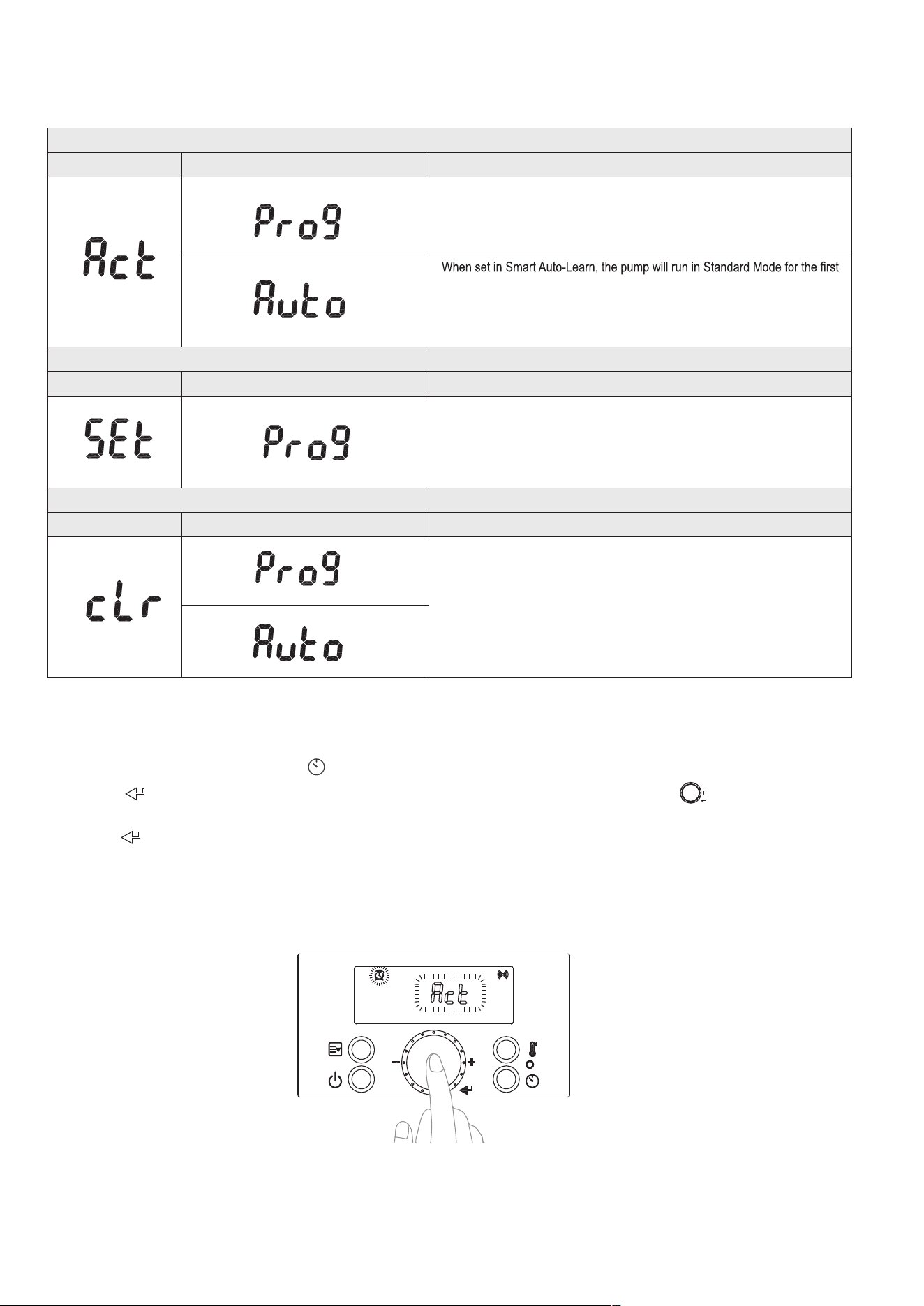
There are three Recirculation Timer settings: Act, SEt, and cLr. Act is used to set the Recirculation Timer type. SEt is used to manually set the day
and times when the Recirculation Function will be active. cLr is used to clear and reset the Recirculation Timer setting.
Setting Detail Description
Preheat or Internal Recirculation Mode Turns on Internal Recirculation
External Recirculation Mode or On Demand Application Turns on External Recirculation
Comply with Title 24 Regulation Turns on External Recirculation
Applied with Crossover valve included Turn on Internal Reciculation
Table 27 – Internal / External Recirculation Mode Overview
AP18733 REV. 3.2.17
64
The following section details the various Recirculation Timer Functions.
Step 1: Set the Recirculation Timer Type.
Setting Detail Description
Allows the installer to customize the Recirculation Function. The recirculation day
and time values must be set in Step 2, SEt.
seven (7) days. During this period the water heater will monitor and record hot
water usage patterns. After the initial seven (7) day learning period, the water
heater will use the preceding week’s usage pattern to cycle the pump and
preheat the water.
Step 2: Set the Recirculation Run Time.
Setting Detail Description
Pro9 is a factory set recirculation run time setting with day and time values.
This setting can be customized for your installation. Day and Time can be
programmed. Default: 6 - 7:30AM, 6 - 7:30 PM
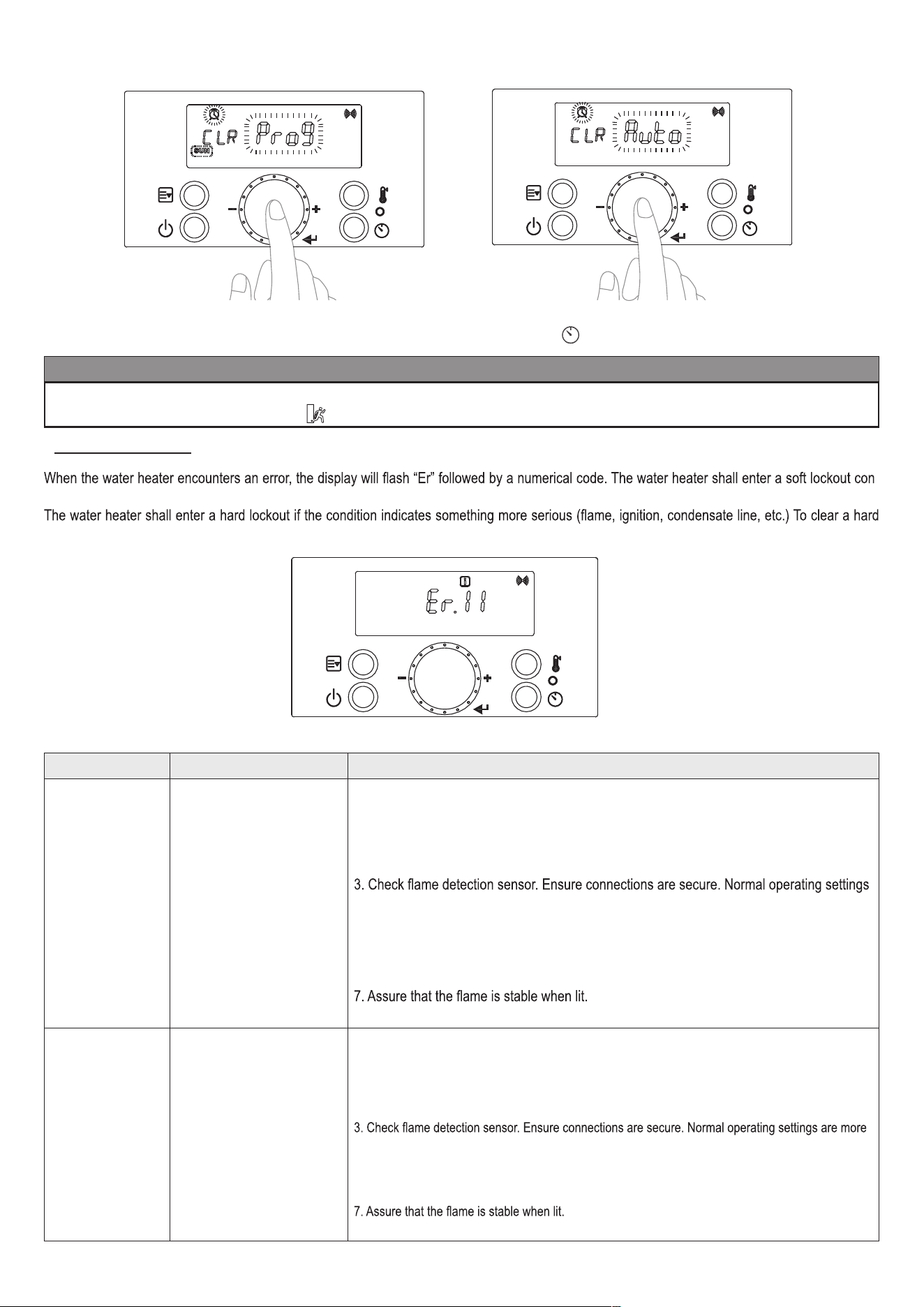
Step 3: Reset the Recirculation Run Time setting.
Setting Setting Setting
Resets the Pro9 or Auto Recirculation Run Time to the factory settings.
Table 28 – Recirculation Function Overview
▪ 1. Set the Recirculation Timer Type
a. Enter the Recirculation Timer by pressing
at Standby Mode while the water heater display is powered on.
b. Press the
button at the “Act” screen to select the Recirculation Timer type. See Figure 41. Turn the dial to choose between “Auto”
or “Pro9”.
c. Press the
button to select the Recirculation Timer Type.
d. The Recirculation Timer Type is now set.
NOTE: If “Auto” is selected, the water heater will monitor and record hot water usage patterns over a period of seven (7) days. After this learn-
ing period, the water heater will use the usage pattern to automatically cycle the pump and preheat the water.
NOTE: If “Pro9” is selected, continue to step 2 below to set the recirculation run time setting.
Figure 41 – Setting the Recirculation Timer Type
AP18733 REV. 3.2.17
65
NOTE: This step is only necessary if “Pro9” was selected as the Recirculation Timer Type. If “Auto” was selected the water heater will automatical-
ly program its recirculation operating patterns.
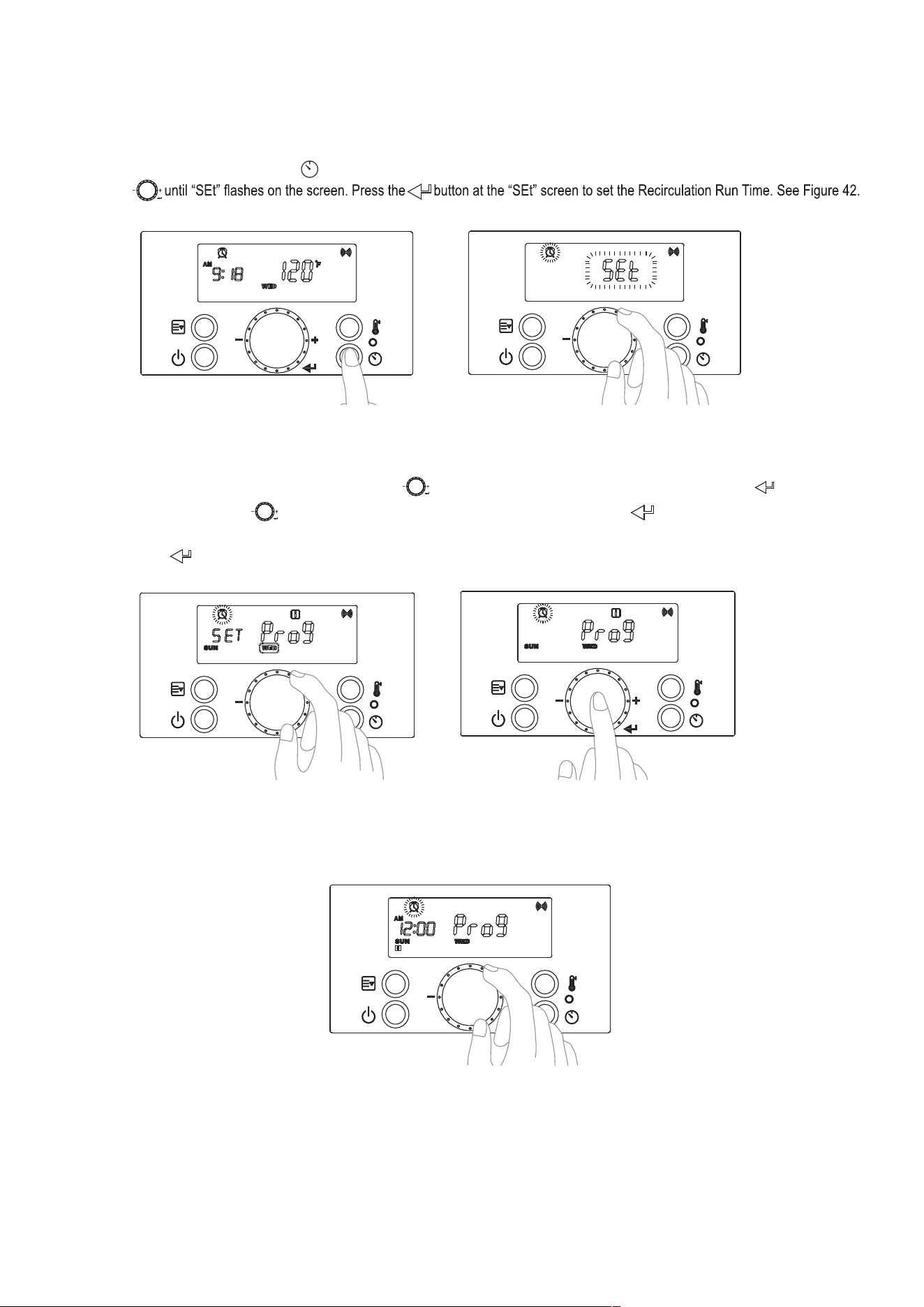
a. Enter the Recirculation Timer by pressing at Standby Mode while the water heater display is powered on.
b. Turn the dial
▪ 2. Setting the Recirculation Run Time (Pro9 Recirculation Timer)
Figure 42 – Setting the Recirculation Run Time
c. To set the day, ensure “Pro9” is on the display. Turn the dial When the desired day appears on the screen, press the button to se-
lect and store the day. Turn the dial
until the next desired day appears on the display. Press the button to select and store the day.
Repeat this step to include more days.
d. Press and hold the
button for two (2) seconds to set the time.
Figure 43 – Setting the Recirculation Day – In this Example, Sunday and Wednesday Are Chosen
e. To set the time, ensure “Pro9” and “12:00” are on the display.
Figure 44 – Setting the Recirculation Time
AP18733 REV. 3.2.17
66
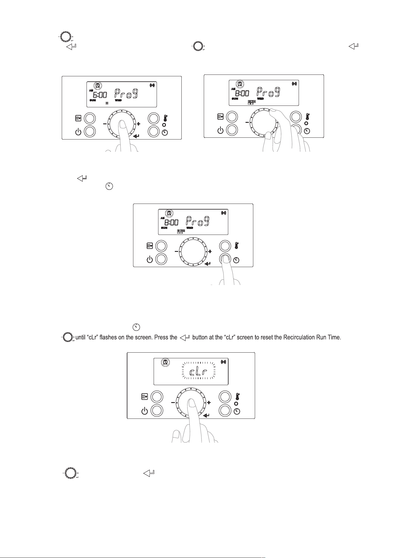
f. Turn the dial . The start time on the screen will change in increments of thirty (30) minutes. When the desired start time appears on the
screen, press the button to select and store it. Next, turn the dial until the desired end time appears on the display. Press the
button to select and store the end time. Repeat this step to set the start and end times for more days.
Figure 45 – Setting Start and End Recirculation Times
g. Press and hold the button for two (2) seconds to store the time.
h. If all settings are stored, press to return to Standby Mode.
Figure 46– Storing Recirculation Run Time
▪3. Resetting the Recirculation Run Time
NOTE: This step is only necessary if the “Pro9” or “Auto” Recirculation Run Times need to be reset. If “Auto” was selected the water heater
will automatically program its recirculation operating patterns.
a. Enter the Recirculation Timer by pressing at Standby Mode while the water heater display is powered on.
b. Turn the dial
See Figure 47.
Figure 47 – Resetting the Recirculation Run Time
c. Turn the dial to “Pro9” or “Auto”. Press at the Recirculation Timer Type you wish to reset. See Figure 48.
AP18733 REV. 3.2.17
67
Figure 48 – Resetting the Recirculation Run Time
d. The Recirculation Run Time has now been reset to the factory default settings. Press to return to Standby Mode.
NOTICE
If hot water is not used for more than thirty (30) hours, the recirculation program will be stopped and the water heater will automatically go into
Vacation Mode and display the vacation icon .
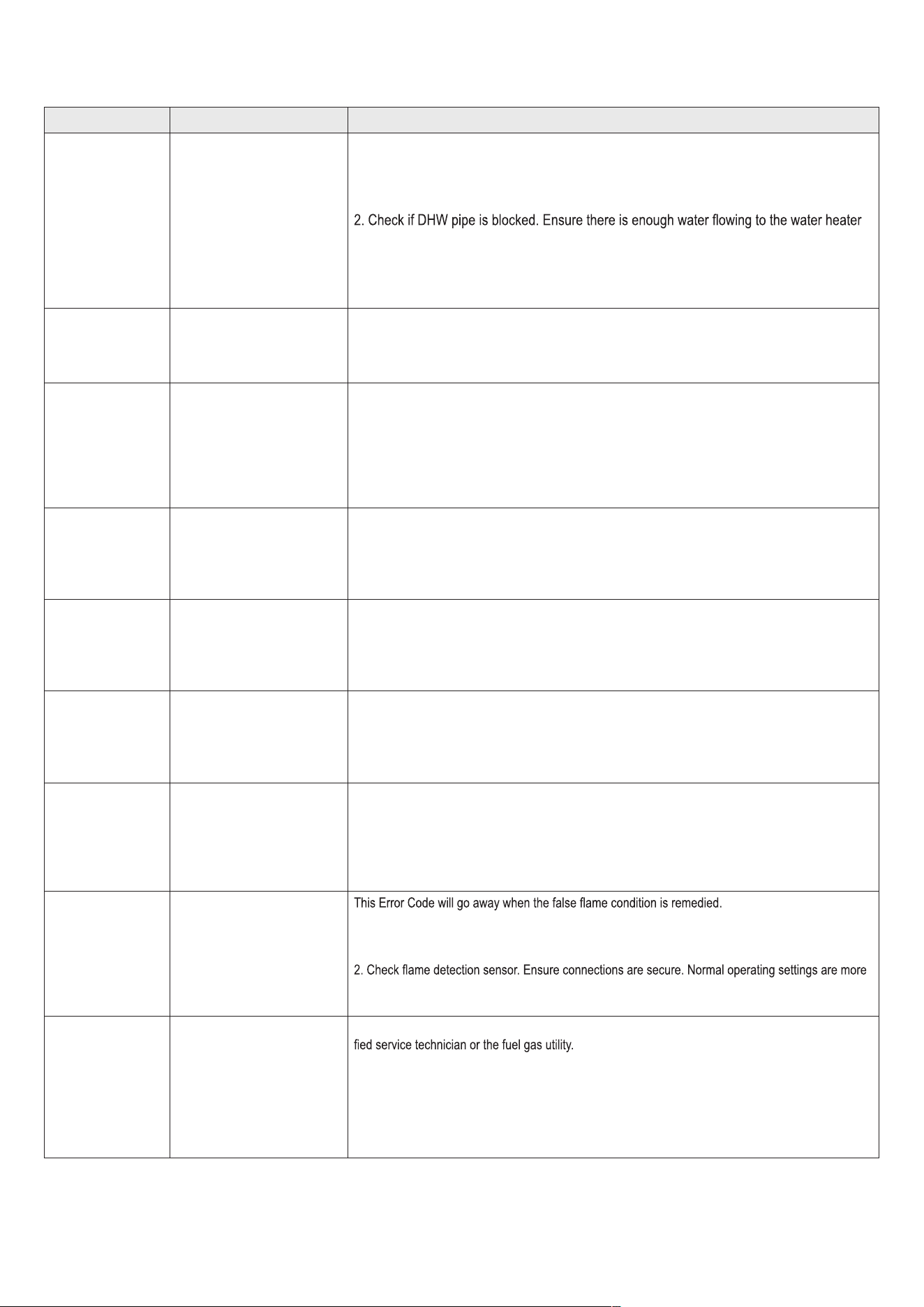
▪ J. ERROR MODE
-
dition if the error is such that it can return to normal operation once the condition relieves itself (overheat conditions, NTC open or shorts, etc.).
lockout Error Code, press the Power button. The following screen will display when the water heater encounters an error.
Figure 49 – Error Mode Screen
Error Code Error Code Description Possible Remedies
Er:10
Flame has been lost Eight (8)
Times
Press the Power button to clear the Error Code.
If Error happens again:
1. Monitor the gas pressure to the water heater while in operation. Ensure pressure is be-
tween 5.0" W.C and 13.0" W.C (1.25 to 3.24 kPa).
2. Check gas valve wire. Ensure connection is secure.
are more than 2.5DC before ignition, less than 2.5DC after ignition.
4. Check igniter transformer for proper connection.
5. Clean the spark igniter with steel wool to remove oxides. Ensure proper separation (3-4
mm).
6. Replace the spark igniter if damaged.
8. If the problem persists, replace the main control.
Er:11
Ignition has Failed 10 (Ten)
Times
Press the Power button to clear the Error Code.
If Error happens again:
1. Monitor the gas pressure to the water heater while in operation. Ensure pressure is between
5.0"
W.C and 13.0" W.C (1.25 to 3.24 kPa).
2. Check gas valve wire. Ensure connection is secure.
than 2.5DC before ignition, less than 2.5DC after ignition.
4. Check igniter transformer for proper connection.
5. Clean the spark igniter with steel wool to remove oxides. Ensure proper separation (3-4 mm).
6. Replace the spark igniter if damaged.
8. If the problem persists, replace the main control.
AP18733 REV. 3.2.17
68
Error Code Error Code Description Possible Remedies
Er:16
Operating Temperature Sen-
sor or DHW Sensor detects
Water Temperature Greater
than 199°F (93°C)
This Error Code will go away when the DHW temperature decreases.
If Error happens again:
1. Check if dip switch High Fire setting is ON. Switches 6 and 7 should be OFF for normal
operation.
.
3. Check DHW sensor at DHW outlet. If resistance is zero, replace the sensor.
4. Check Operating Temperature sensor at the heat exchanger. If resistance is zero, replace
the sensor.
5. If the problem persists, replace the main control.
Er:20
High Limit Overheat Switch
– Closed is Normal, Open is
Fault
Press the Power button to clear the Error Code.
1. Inspect the High Limit Overheat switch. Ensure proper connections.
2. Check High Limit Overheat switch resistance. If resistance is zero, replace the switch.
3. If the problem persists, replace the main control.
Er:29
APS/Condensate – Closed
is Normal, Open is Fault
(Condensate Drain Trap)
Press the Power button to clear the Error Code.
1. Check APS/Condensate and main controller connections. Ensure all are secure.
2. Check APS/Condensate resistance. If resistance is zero, replace the switch.
3. Check APS/Condensate hose. Ensure it is connected and in good condition.
4. Check condensate line and termination for blockages.
5. Check exhaust vent for blockages.
6. If the problem persists, replace the main control.
Er:31
Water Inlet Sensor Open or
Short
This Error Code will go away when inlet water temperature decreases.
If Error happens again:
1. Check inlet water temperature sensor. Ensure connections are secure.
2. Check sensor resistance. If resistance is zero, replace the sensor.
3. If the problem persists, replace the main control.
Er:32
Water Outlet Sensor Open or
Short
This Error Code will go away when outlet water temperature decreases.
If Error happens again:
1. Check DHW outlet temperature sensor. Ensure connections are secure.
2. Check sensor resistance. If resistance is zero, replace the sensor.
3. If the problem persists, replace the main control.
Er:33
H/X Temperature Sensor
Open or Short
This Error Code will go away when outlet water temperature decreases.
If Error happens again:
1. Check operating temperature sensor. Ensure connections are secure.
2. Check sensor resistance. If resistance is zero, replace the sensor.
3. If the problem persists, replace the main control.
Er:35
Exhaust Sensor Open or
Short
This Error Code will go away when exhaust temperature decreases.
If Error happens again:
1. Check exhaust temperature sensor. Ensure connections are secure.
2. Check sensor resistance. If resistance is zero, replace the sensor.
3. Check exhaust vent for blockage.
4. If the problem persists, replace the main control.
Er:39
Flame Detected after Exiting
a Flame On Condition
If Error happens again:
1. Check the water heater cover. Ensure it is secure. Flame detection sensor can detect an external
light source.
than 2.5DC before ignition, less than 2.5DC after ignition.
3. If the problem persists, replace the main control.
Er:40
Gas Leakage continuously
detected for 10 Minutes, or
three times within One Hour
(Greater than 5 Seconds
Each Time)
IMPORTANT: If you smell gas, STOP! Follow the instructions on page 2, this manual, and call a quali-
Press the Power button to clear the Error Code.
If Error happens again:
1. Check the water heater cover. Ensure it is secure.
2. Check gas connections for leakage with a soapy solution. Fix any leaks.
3. Check condition of the burner assembly.
4. If the problem persists, replace the main control.
AP18733 REV. 3.2.17
69
Error Code Error Code Description Possible Remedies
Er:41
Fan Speed too High with
Flame On
Press the Power button to clear the Error Code.
If Error happens again:
1. Check the vent connections for blockages.
2. Check the burner assembly.
3. Check fan operation. If fan appears to be operating normally but RPMs are too low or too
high, replace the fan.
4. If the problem persists, replace the main control.
Er:43
Burner Overheat Switch
Open
Press the Power button to clear the Error Code.
If Error happens again:
1. Check burner overheat switch connections. Ensure connections are secure.
2. Check switch resistance. If resistance is zero, replace the switch.
3. If the problem persists, replace the main control.
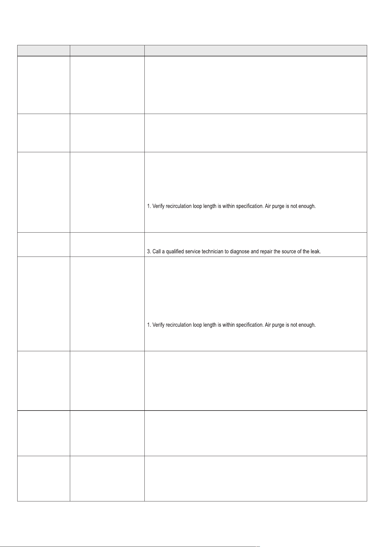
Er:44 Recirculation Abnormality
Press the Power button to clear the Error Code.
If Error happens again:
1. Ensure water heater inlet and outlets are open and water is supplied to the water heater.
2. Check the pump operation.
3. If it doesn’t work, ensure wiring connections to pump.
4. If even supply power to pump and doesn’t run it replace the pump.
If Error happens again:
2. Too much restriction on recirculation loop.
3. Return loops are clogged.
4. Check the recirculation loop condition
Er:45 Water Leak
1. Turn power off to the water heater.
2. Valve off the water heater to isolate it from the system.
Er:60
Hot Water Temperature
Abnormality
Press the Power button to clear the Error Code.
If Error happens again:
1. Ensure water heater inlet and outlets are open and water is supplied to the water heater.
If Error happens again:
1. Ensure water heater inlet and outlets are open and water is supplied to the water heater.
2. Check the pump operation.
3. If it doesn’t work, ensure wiring connections to pump.
4. If even supply power to pump and doesn’t run it, replace the pump.
If Error happens again:
2. Too much restriction on recirculation loop.
3. Return loops are clogged.
4. Check the recirculation loop condition.
Er:61
Fan Speed Feedback Signal
Abnormal
This Error Code will go away when the condition is remedied.
If Error happens again:
1. Check the connections to the fan. Ensure all are secure.
2. If the fan does not rotate during the ignition sequence, check for DC15~30V power at the fan
connection. If DC15~30V power is present at the control, replace the fan. If the blower does not
have DC15~30V power, check power at the control. If DC15~30V power is not present at the control,
replace the control.
3. If the problem persists, replace the main control.
Er:65 Supply Water Valve Error
Press the Power button to clear the Error Code.
If Error happens again:
1. Turn power OFF and ON at the main power switch internal to the water heater.
2. Check wiring connections to supply water valve. Ensure all are secure.
3. Replace supply water valve.
4. If the problem persists, replace the main control.
Er:66 Mixing Valve Error
Press the Power button to clear the Error Code.
If Error happens again:
1. Turn power OFF and ON at the main power switch internal to the water heater.
2. Check wiring connections to mixing valve. Ensure all are secure.
3. Replace mixing valve.
4. If the problem persists, replace the main control.

AP18733 REV. 3.2.17
70
Error Code Error Code Description Possible Remedies
Er:67 AGM Error
Press the Power button to clear the Error Code.
If Error happens again:
1. Turn power OFF and ON at the main power switch internal to the water heater.
2. Ensure fan inlet hole is completely open after turning the power OFF and ON.
3. Check wiring connections to the AGM. Ensure all are secure.
4. Check AGM operation.
5. Replace AGM components.
6. If the problem persists, replace the main control.
Er:72
Flame Signal Detected
before Ignition
This Error Code will go away when the condition is remedied.
If Error happens again:
1. Check the water heater cover. Ensure it is secure. Flame detection sensor can detect an
external light source.
are more than 2.5DC before ignition, less than 2.5DC after ignition.
3. If the problem persists, replace the main control.
Er:73 DIP Switch is abnormal
This Error Code will go away when the condition is remedied.
If Error happens again:
1. Check dip switches. Ensure switches match the ratings plate requirements of the water heater. See
dip switch details, this manual, for default settings.
2. If the problem persists, replace the main control.
Er:76 Poor Communication
This Error Code will go away when the condition is remedied.
If Error happens again:
1. Check connections from main control to display panel.
2. If the problem persists, replace the display and/or the main control.
Er:78
Cascade Communication
Error
NOTE: This error will only appear in a cascaded system.
1. Turn power OFF and ON at the appliance display panel.
2. If error reappears, ensure all cascaded appliances are powered ON.
3. If error reappears, check Installer Mode parameter 10:Cn at among the both units.
Ensure the setting as “on” in 10:Cn of Installer Mode.
4. If error reappears, check the wire cables into the ‘Main PCB’ connector inside both units.
Ensure the connection of cascade cable between both appliances.
5. If there was no problem wiring connection, replace damaged cables.
6. If the problem persists, replace the main control.
Er:94
Exhaust NTC detects Vent
Temperature is Greater than
149°F/ 65°C
(185°F / 85°C when High
Temp set point is Selected)
This Error Code will go away when the condition is remedied.
If Error happens again:
1. Check if dip switch High Fire setting is ON. Switches 6 and 7 should be OFF for normal operation.
2. Check exhaust temperature sensor. Ensure connections are secure.
3. Check sensor resistance. If resistance is zero, replace the sensor.
4. Check exhaust vent for blockage.
5. If the problem persists, replace the control.
6. If the problem persists, replace the heat exchanger.
Table 29 –Diagnostics and Suggested Corrective Actions
AP18733 REV. 3.2.17
71
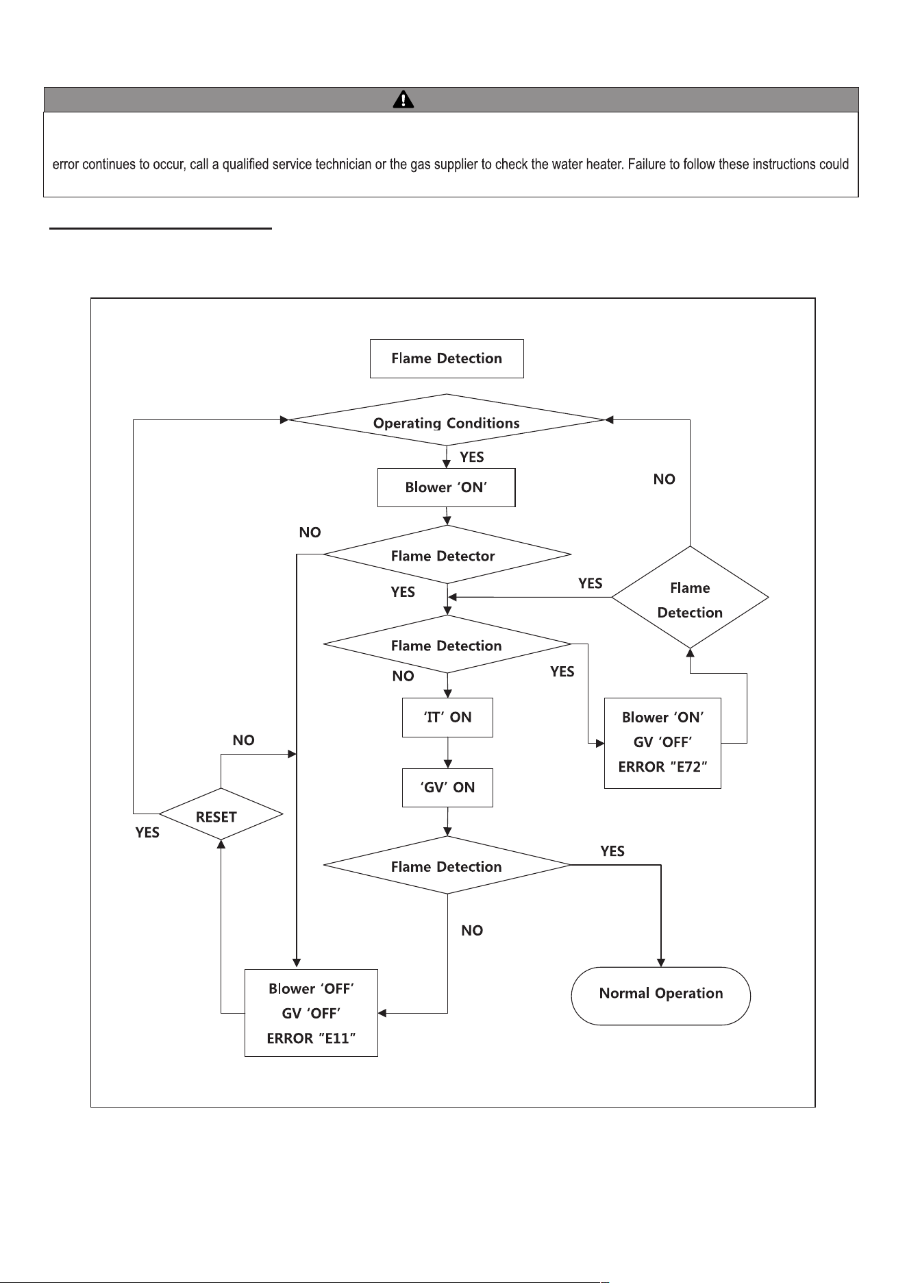
WARNING
This water heater is equipped with a blocked vent shutoff system. If Error Codes Er:29, Er:41 or Er:94 occur, turn off the gas valve at the manual
shutoff. Check the vent terminations for obstructions. If no obstructions are found, reset the water heater by pressing the power button. If the
result in property damage, personal injury, or death.
▪ K. ERROR TREE ANALYSIS
1. FLAME DETECTION
Figure 50 – Flame Detection Error Analysis Tree
AP18733 REV. 3.2.17
72
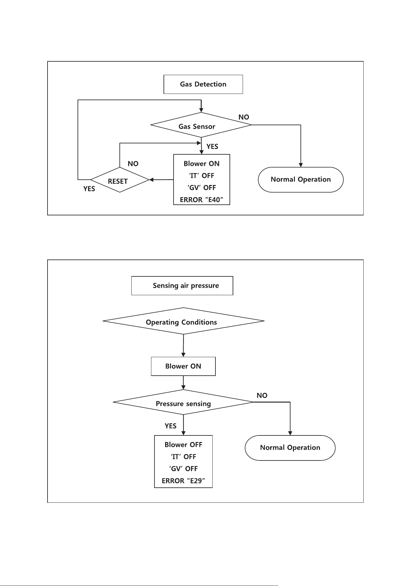
2. GAS DETECTION
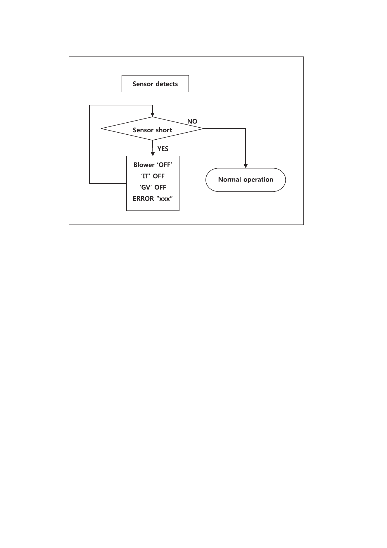
3. AIR PRESSURE SWITCH
Figure 51 – Gas Detection Error Analysis Tree
Figure 52 – Air Pressure Switch Analysis Tree
AP18733 REV. 3.2.17
73
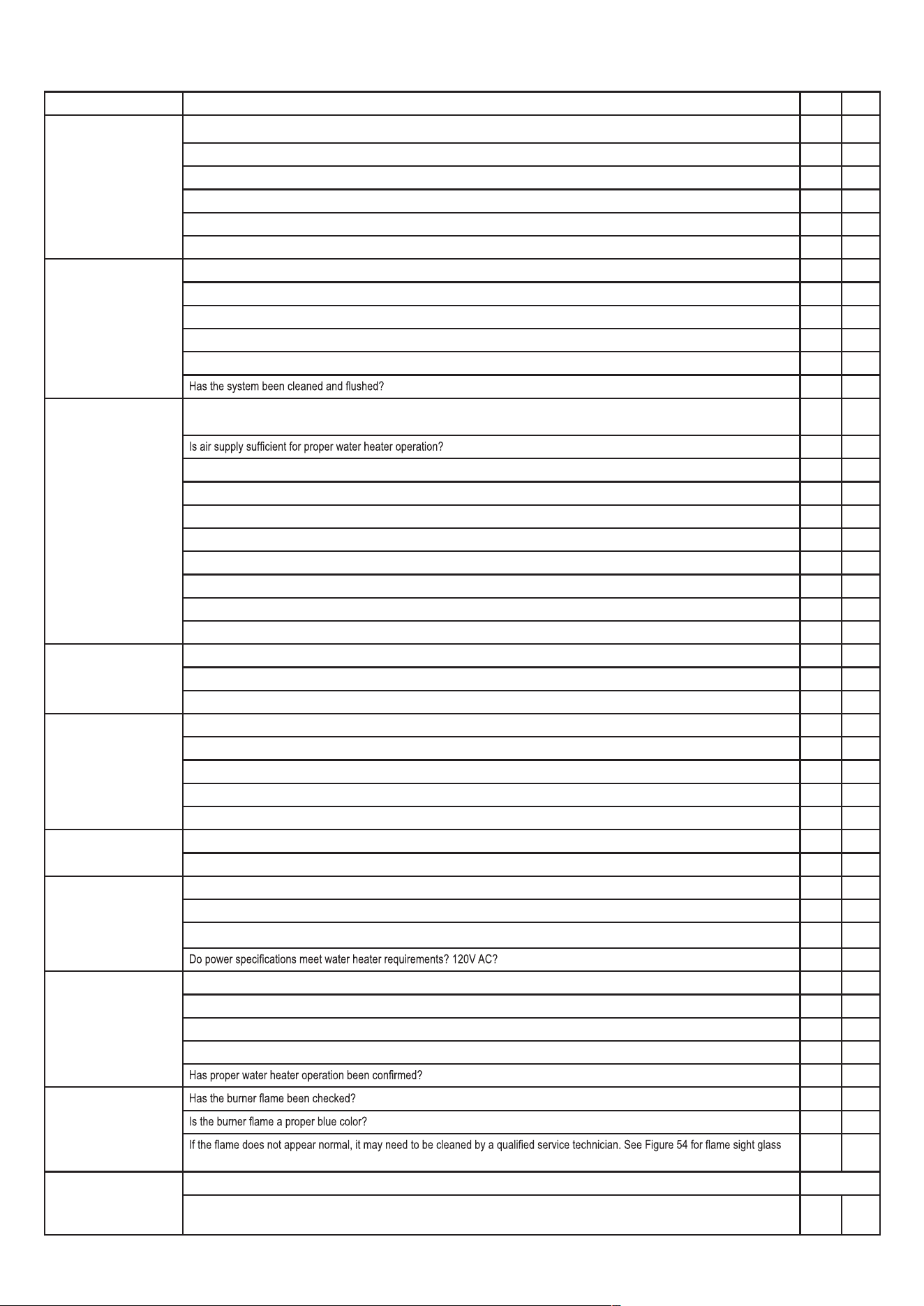
4. Inlet / DHW / Operating Temperature SENSORS
Figure 53 – Inlet / DHW / Operating Temperature Sensors Error Analysis Tree
AP18733 REV. 3.2.17
74
FINAL INSTALLATION CHECKLIST
YES NO
BEFORE INSTALLING
Is there enough space to ensure proper installation?
Does installation location allow for proper service clearances?
Are water and gas lines properly sized and set at proper pressures for the installation?
Is water heater location as near the exhaust vent / intake pipe terminations as possible?
Have combustible materials been cleared from the installation location?
Is there a drain close to the water heater?
INSTALL WATER PIPING
Does water heater loop piping meet the minimum sizing requirements listed?
NOTE: Smaller piping will cause performance problems.
Has water chemistry been checked?
Does water chemistry meet requirements?
If water chemistry does not meet requirements, have treatment measures been put in place?
INSTALL EXHAUST VENT
AND INTAKE PIPING
Has the water heater been vented with the approved materials listed in this manual (3" [7.6 cm] PVC, CPVC, Polypropylene, etc.) or to
meet local codes?
Is total vent piping length within the maximum vent length restriction listed in this manual?
Have venting lengths been minimized?
Are terminations properly spaced from windows, doors, and other intake vents?
Have all vent terminations been installed at least one foot above exterior grade and one foot above normal snow accumulation level?
Is vent piping properly supported?
Has vent piping been checked for leaks?
Has the exhaust vent line been pitched back to the water heater at a rate of ¼" (0.6 cm) per foot?
Have the exhaust vent and intake pipes been properly installed into the connectors provided on the water heater?
INSTALL CONDENSATE
PIPING / TUBING AND
COMPONENTS
Have all condensate line components included with the water heater been installed?
Is the condensate line piped with the approved materials listed in this manual?
Has the condensate line been routed to a laundry tub or other drain?
INSTALL GAS PIPING
Is the gas supply line a minimum of ¾" (1.9 cm) in diameter?
Is the gas supply line length and diameter adequate to deliver the required BTUs?
Has gas supply line pressure been measured?
Does the gas type match the type indicated on the water heater rating plate?
Has a union and shut-off valve been installed?
PRESSURE RELIEF
VALVES
Have you installed approved pressure relief valves on the hot water outlet near the water heater?
Is the pressure relief valve in the DHW line at least ¾" (1.9 cm) in diameter?
WIRE THE WATER
HEATER
Connect the power and control wiring per water heater wiring diagram, this manual.
Have all DIP switches been set on the main water heater board?
Is electrical connection polarity within water heater requirements?
START-UP, ADJUST, AND
TEST
Has the water heater been started?
If necessary, has the water heater gas valve been adjusted?
Has the installation been customized per installation location requirements?
Have all customized system parameters been tested?
BURNER FLAME
window location.
FINAL INSTALLATION
APPROVALS
SIGNED BY TECHNICIAN DATE
AP18733 REV. 3.2.17
75
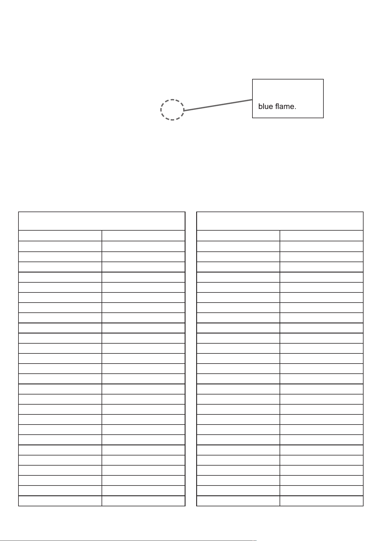
Figure 54 – Flame Sight Glass
DHW Inlet Temperature Sensor (7850P-015) Exhaust Temperature
Sensor (7850P-070)
Temperature (°F/ °C) Resistance (Ω)
Resistance (Ω)
-4 / -20 28409
5 / -15 22152
14 / -10 17408
23 / -5 13782
32 / 0 10990
41 / 5 8824
50 / 10 7131
59 / 15 5800
68 / 20 4747
77 / 25 3906
86 / 30 3233
95 / 35 2690
104 / 40 2250
113 / 45 1891
122 / 50 1598
131 / 55 1356
140 / 60 1155
149 / 65 989
158 / 70 850
167 / 75 733
176 / 80 635
185 / 85 552
194 / 90 482
203 / 95 421
212 / 100 370
DHW Inlet Temperature Sensor (7850P-015) Exhaust Temperature
Sensor (7850P-070)
Temperature (°F/ °C) Resistance (Ω)
Resistance (Ω)
-4 / -20 62162
5 / -15 48440
14 / -10 38045
23 / -5 30107
32 / 0 23998
41 / 5 19261
50 / 10 15562
59 / 15 12655
68 / 20 10353
77 / 25 8520
86 / 30 7051
95 / 35 5867
104 / 40 4908
113 / 45 4125
122 / 50 3485
131 / 55 2957
140 / 60 2520
149 / 65 2157
158 / 70 1854
167 / 75 1600
176 / 80 1386
185 / 85 1205
194 / 90 1051
203 / 95 920
212 / 100 808
Visual check Port
Port should show
AP18733 REV. 3.2.17
76
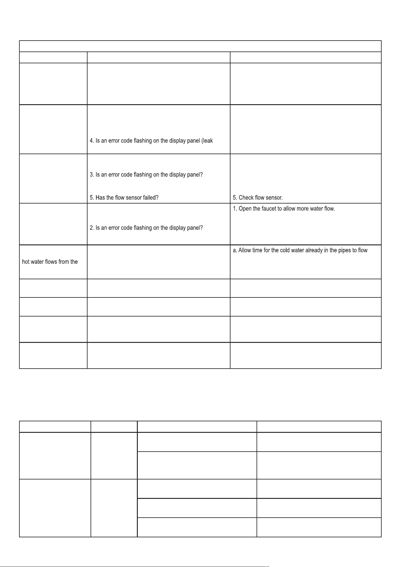
Table 30 – Troubleshooting Chart
TROUBLESHOOTING CHART
PROBLEM POSSIBLE CAUSES POSSIBLE REMEDIES
No electrical power to the
water heater
1. Is the plug on the power supply cord unplugged from the
electrical outlet?
2. Is electrical panel’s 10 Amp circuit breaker tripped?
3. Is the fuse on the circuit board good?
4. Is there a power outage to the home?
1. Reset the plug.
2. Reset the circuit breaker.
3. If the display panel is blank, unplug the unit or contact an
authorized service technician.
4. Contact the power company.
No water available when a
faucet is opened
1. Is the water supply valve shut off at the meter
(do cold water faucets work)?
2. Is the water supply valve near the unit open?
3. Is the water pipe frozen?
detected)?
1. Open the closed supply valve.
2. Open the water supply valve.
3. Turn OFF the unit, close all water valves and the gas valve.
Contact an authorized service technician.
4. Refer to error code information and contact an authorized
service technician.
Hot water is not available
when the faucet is opened.
1. Does the water heater have power (plugged in)?
2. Is the water heater turned ON?
4. Is the gas supply valve open or shut off at the meter
(do other gas devices work)?
1. Restore electrical power to the unit.
2. Press and hold the Power button to turn the unit ON.
3. Refer to the Diagnostic and Error Codes section in this
manual.
4. Open the gas supply valve.
The water temperature is
not hot enough or turns
cold during use.
1. Is the faucet open enough to draw at least 0.6 gallons
(2.3L) per minute through the water heater?
3. Is the outlet water temperature set too low?
2. Refer to the Diagnostic and Error Codes section in this
manual.
3. Adjust the outlet water temperature (refer to the procedure
in this manual).
It takes a long time before
faucet.
Is the faucet some distance from the water heater?
from the faucet.
b. Have recirculation valves and/or plumbing return line(s)
installed and program the unit for recirculation mode.
The water is not hot
enough.
Is the water temperature set too low? Adjust the temperature setting.
The water at the faucet is
too hot.
Is the water temperature set too high? Adjust the temperature setting.
A fan can be heard even
when the unit is not
operating.
1. The fan continues to operate after the burner shuts off to
clear the exhaust vent of combustion gases.
2. The fan may run to help prevent freezing.
1. This is normal operation – no action is required.
2. Protect the water heater from freezing temperatures or shut
off and drain the unit.
White “smoke” can be
seen coming out of the
exterior exhaust gas vent.
Depending on the outside temperature, water vapor can be
produced as the exhaust is vented.
This is normal operation – no action is required.
DIAGNOSTICS AND SUGGESTED CORRECTIVE ACTIONS
The water heater control is able to record information about the water heater’s condition at the time of the ten previous faults or errors.
This information is available to view in the Installer Mode under the History screen. The following screens may be displayed when reviewing
the water heater history. The table below also includes diagnostic information and possible corrective actions.
Display Condition Diagnostic Possible Corrective Actions
Nothing appears on the
display control panel but
the fan runs at full speed
Control is not
receiving power
Check wiring for short circuit or incorrect wiring
Correct wiring per wiring diagram including
connection of transformer to the control
Check transformer connection to the control
per wiring diagram. Check for 14V output of
panel wire
Push the Power button on the control panel
Nothing appears on the
display control panel and
no other water heater
components are operating
Control is not
receiving 120V
power
Ensure service switch and/or circuit breaker to
water heater is turned ON
Turn on service switch or circuit breaker to
power water heater
Is there 120V at the service switch
Troubleshoot and correct the power supply to
the manual switch
Is the ON/OFF switch inside the water heater
cabinet is turned on
Turn ON the manual power switch inside the
water heater cabinet
TROUBLESHOOTING
AP18733 REV. 3.2.17
77
Check for 120V at the line voltage terminal block
located inside the water heater cabinet
Correct wiring inside the water heater cabinet using
the wiring diagram in the installation manual
Inspect the fuse. Replace as necessary
Replace the fuse with the proper part found in the
replacement part section of this manual. If fuse
blows again, recheck the wiring per diagram
Nothing appears on
the display control
panel, but the water
heater is operating
Occurs when
communications
is lost from the
control to the
display
Check for loose connections and proper pin
alignment / engagement on the control’s plug
Check for continuity on the wire harness from the
display to the control. See repair parts section for
proper replacement part.
Cycle power off and on using water heater
power switch and check for operation
Replace with new display module. See repair parts
section for proper replacement part.
Display repeatedly
goes through
initialization sequence
Occurs when
control does not
receive signal
from fan
Cycle power off and on using appliance power
switch and check for operation
Replace fan.
Table 31 –Diagnostics and Suggested Corrective Actions
MAINTENANCE PROCEDURES
DANGER
DANGER
addition, the maintenance and care of the water heater as outlined in this manual must be performed by the user/owner to assure maximum
follow the directions in this manual could damage the water heater or system components, resulting in substantial property damage, severe
personal injury, or death.
To prevent the potential of substantial property damage, severe personal injury, or death, eliminate all the materials listed in Table 1 from the area
surrounding the water heater and the vicinity of the combustion air intake. If contaminates are found:
● Remove products immediately from area.
●
from acid corrosion.
If products cannot be removed, immediately call a qualified service technician to re-pipe the combustion air intake piping away from the
contaminated areas.
Combustible/Flammable Materials
immediately.
Air Contaminates
damage to the water heater. Read the list of potential contaminates and areas likely to have these contaminates in Table 1. If any of these
contaminates are in the room where the water heater is located, or combustion air is taken from one of the areas listed, the contaminates must
be removed immediately or the intake pipe must be relocated to another area.
Ensure the Water Heater Cabinet is Closed
Ensure the water heater cabinet is closed. Tighten the two upper and lower screws to secure it. The cabinet must be closed while the water
heater is running.
Check the Power Source
Make sure the power cord is properly connected. The main power line is connected to the manual switch box inside the water heater.
Check the Status of the Control Panel
Observe the Control Panel to ensure the water heater is powered on, and to check for any error codes. Clear any debris from the panel.
Check Exhaust Vent and Intake Pipe Terminations
Verify that the water heater exhaust vent and intake pipe terminations are clean and free of obstructions. Remove any debris from the exhaust
vent or intake pipe openings. If removing the debris does not allow the water heater to operate correctly, contact your qualified service
technician to inspect the water heater and the vent system.
Check Exhaust Vent and Intake Piping
Visually inspect the exhaust vent for any signs of blockage, leakage, or deterioration of the piping. Inspect the exhaust vent bracing. Ensure
AP18733 REV. 3.2.17
78
Visually inspect the intake piping for any signs of blockage. Inspect the entire length of the intake pipe to ensure piping is intact and all joints are
problems are found.
Check Pressure Relief Valve
● Visually inspect the primary pressure relief valve and discharge pipe for signs of weeping or leakage.
● If the pressure relief valve often weeps, the expansion tank m
to inspect the water heater and system.
Check the Condensate Drain System
● While the water heater is running, check the discharge end of the condensate drain tubing. Ensure no flue gas is leaking from the
●
● If applicable, check the condensate neutralizer and ensure it is full of condensate neutralizing marble chips.
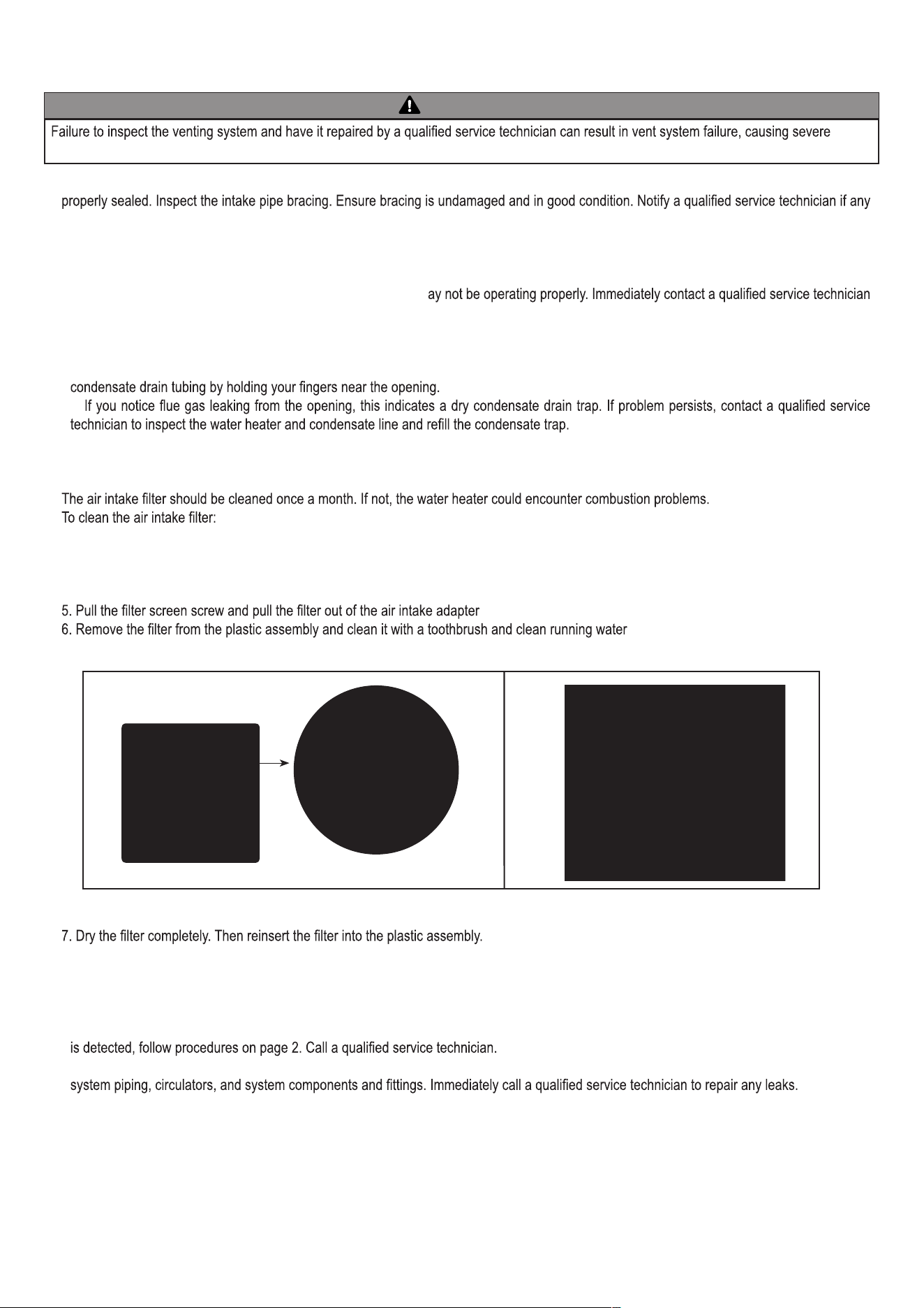
Cleaning the Air Intake Filter
1. Press the Power button on the control panel to turn off the water heater.
2. Disconnect the power supply from the water heater.
3. If water heater has been operating, wait for it to cool before continuing.
4. Remove the front cover of the water heater cabinet.
.
. See Figure 55.
8. Replace the front cover of the water heater cabinet. Reconnect power supply to the water heater.
9. Press the Power button on the control panel to turn on the water heater.
Check Primary and Gas Piping
●Remove the water heater cover and perform a gas leak inspection following Operating Instructions, page 2, this manual. If gas odor or leak
● Visually inspect for leaks around the internal water heater water connections and around the heat exchanger. Visually inspect the external
WARNING
personal injury or death.
Figure 55 – Cleaning the Air Intake Filter
AP18733 REV. 3.2.17
79
WARNING
WARNING
, or
death.
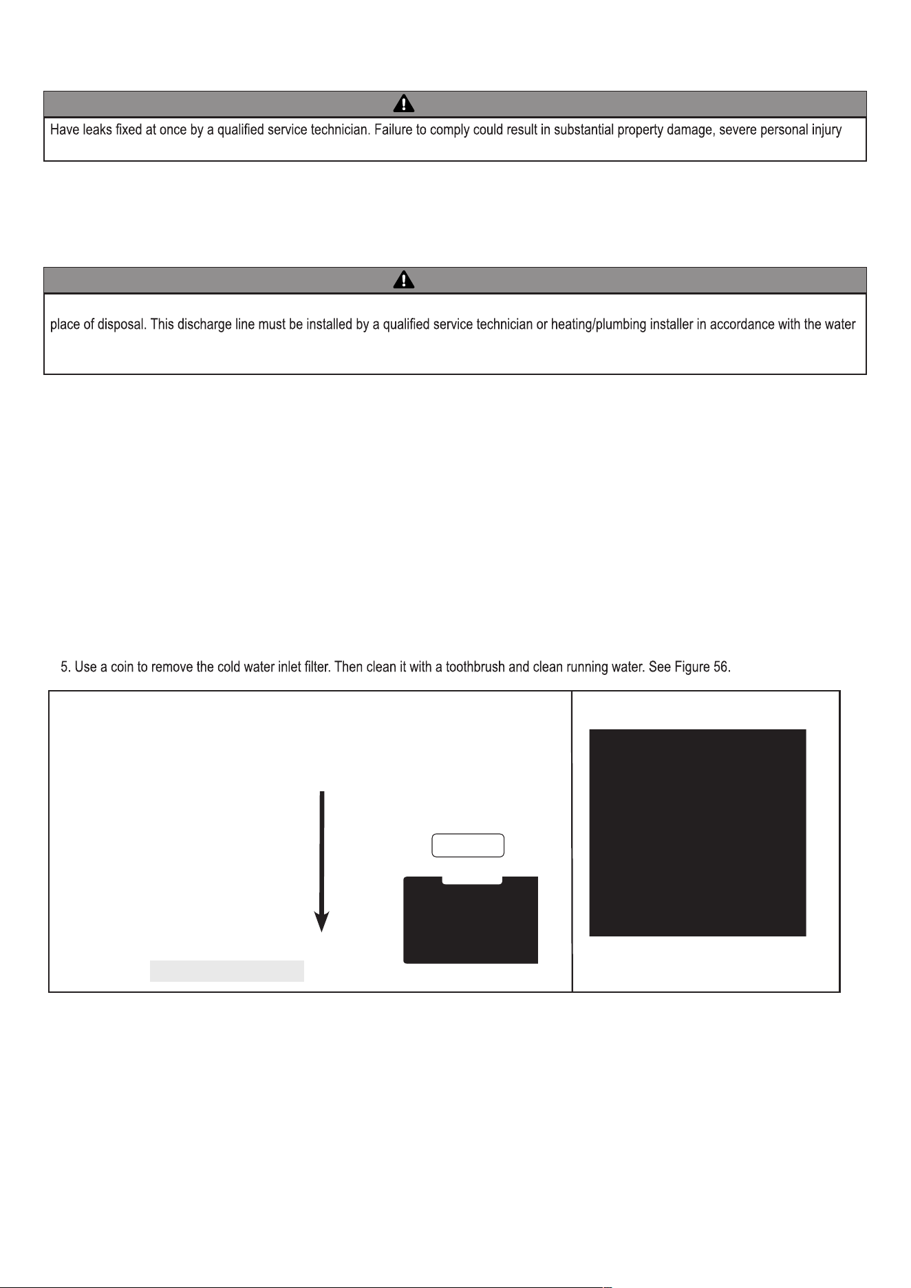
To avoid water damage or scalding due to relief valve operation, a discharge line must be connected to the valve outlet and directed to a safe
heater installation manual. The discharge line must be terminated so as to eliminate possibility of severe burns or property damage should the
valve discharge.
Operate Pressure Relief Valve
● Before proceeding, verify that the relief valve outlet has been piped to a safe place of discharge, avoiding any possibility of scalding from hot
water.
● Shut power off to the water heater. To avoid scalding, wait for water heater to cool before operating the relief valve.
6. Reinstall the cold water inlet filter.
7. Restore water service to the water heater by opening the isolation valves, or turning on the main water valve.
8. Turn on the gas valve. Turn on electrical power to the water heater and press the Power button to turn the water heater on.
●List the relief valve lever. If water flows freely, release the lever and allow the valve to seat. Watch the end of the relief valve discharge pipe
to ensure that the valve does not weep after the line has had time to drain. If the valve weeps, lift the lever again to attempt to clean the valve
seat. If the valve does not properly seat and continues to weep, contact a qualified service technician to inspect the valve and system.
● If water does not flow from the valve when you completely lift the lever, the valve or discharge line may be blocked. Immediately shut the
water heater down per instructions on page 2 and call a qualified service technician to inspect the valve and system.
● If relief valve seats properly, restore power to the water heater. Observe operation for five minutes and ensure it operates properly.
Check the Burner
Clean the exterior of the burner.
Cleaning the Cold Water Inlet Filter (Draining the Water Heater)
1. Place a bucket under the appliance to collect the residual water inside the water heater.
2. Press the Power button on the control panel to turn off the electrical power to the water heater. Then turn off the gas valve.
3. Valve off the water heater from the system. If the water heater cannot be isolated from the system, turn off the main water valve. Open the hot
water faucets in the system to aid in draining the system.
Figure 56 – Draining the Water Heater
Use a coin.
Cold Water Filter
AP18733 REV. 3.2.17
80
Flushing the Water Heater
Flushing the heat exchanger is a complicated procedure that should only be performed by a qualified service technician.
NOTE: Improper maintenance WILL VOID water heater warranty.
1. Disconnect electrical power to the water heater.
2. Close the shutoff valves on both hot water outlet and cold water inlet lines (V1 and V2). See Figure 57.
3. Connect one hose (D1, Figure 57) to the valve (V3) and place the free end in a bucket. Connect one of the hoses (D3) to the circulation pump
outlet and the cold water inlet line to valve V4. Connect the other hose (D2) to the circulation pump inlet and place the free end in the bucket.
4. Pour tankless water heater cleaning solution into the bucket. Ensure the cleaning solution is approved for potable water systems. Place the
drain hose (D1) and hose D2 to the pump inlet in the cleaning solution.
5. Open service valves (V3 and V4) on the hot water outlet and cold water inlet lines.
6. Turn on the circulation pump. Operate the pump and allow the cleaning solution to circulate through the water heater for at least 1 hour at a
rate of 4 gallons per minute. This will remove any possible harmful scale deposits.
7. Rinse the cleaning solution from the combination water heater as follows:
a. Remove the free end of drain hose D1 from the bucket.
b. Close service valve V4 and open shutoff valve V2.
c. Do not open shutoff valve V1.
d. Allow water to flow through the water heater for 5 minutes.
e. Close shutoff valve V2.
8. Disconnect all hoses.
9. Remove the cold water inlet filter from the water heater and clean out any residues.
10. Reinsert the filter and ensure the filter cap is securely tightened.
11. Connect electrical power to the water heater.
12. Open a hot water faucet. Run the water heater continuously for five minutes to ensure all cleaning solution is purged from the system.
Check for leaks and ensure the water heater is operating properly.
Figure 57 – Flushing the Water Heater
V4
D1
D2
D3
V2
V3
V1
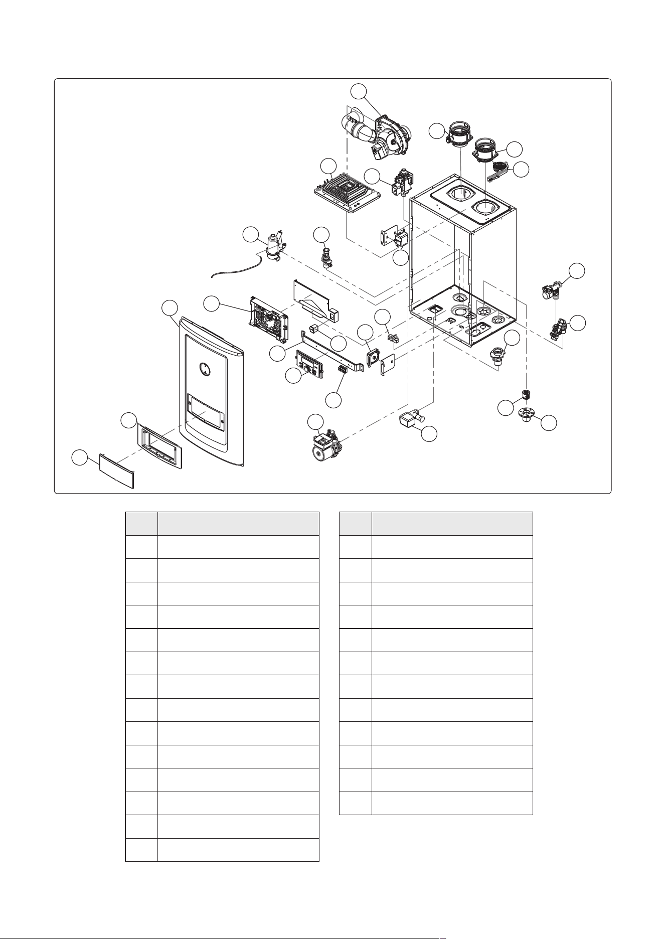
AP18733 REV. 3.2.17
81
Table 32 – Replacement Parts
22
10
19
20
21
11
12
23
3
2
14
15
13
6
18
17
16
1-2
1-1
1
24
8
9
7
4
5
Figure 58 – Replacement Parts
REPLACEMENT PARTS
Ref # Description
1.
Front Cover
1-1.
Control Panel Bracket
1-2.
Control Panel Window
2.
PCB
3.
Control Panel
4.
Circulation Pump
5.
Mixing Valve
6.
Igniter
7.
Gas Valve Assembly
8.
Burner Assembly
9.
Blower & Silencer
10.
Flow Control Valve
11.
Air Pressure Switch
12.
Water Leak Detector
Ref # Description
13.
Hot Water Pipe Assembly
14.
Rocker Switch
15.
Condensate Trap
16.
Exhaust Assembly
17.
Air Intake Assembly
18.
Air Intake Filter
19.
Cold Water Valve Assembly
20.
Recirculation Return Connection
21.
Check Valve
22.
Gas Inlet Connection
23.
Control Panel Steel Bracket
24.
Terminal Block
AP18733 REV. 3.2.17
82
AP18733 REV. 3.2.17
83
800 Interstate Park Drive, Montgomery, Alabama 36019
800 Interstate Park Drive
Montgomery, Alabama 36019
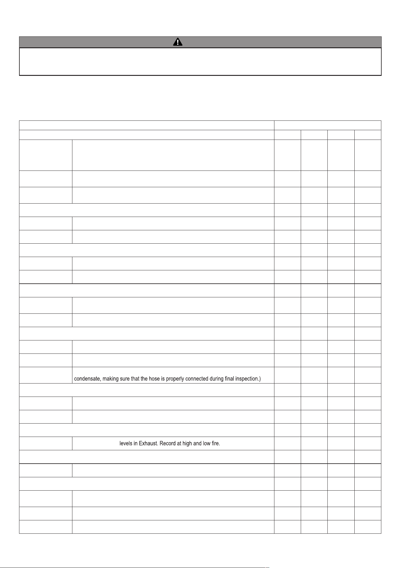
AP18733 REV. 3.2.17
84
WARNING
Allowing the water heater to operate with a dirty combustion chamber will hurt operation. Failure to clean the heat exchanger as needed by the
installation location could result in water heater failure, property damage, personal injury, or death. Such product failures ARE NOT covered under
warranty.
INSPECTION ACTIVITIES DATE LAST COMPLETED
Piping 1st YEAR 2nd YEAR 3rd YEAR 4th YEAR
Near water heater
piping
Check water heater and system piping for any sign of leakage. Leaking pipes could
cause property damage. Make sure all piping is properly supported. Flush tankless heat
exchanger annually (more in hard water conditions). See User’s Information manual for
instructions.
Vent
Check condition of all vent pipes and joints. Ensure all vent piping is properly supported.
Check for obstructions exhaust and intake termination points.
Gas
Check Gas piping, test for leaks and signs of aging. Make sure all pipes are properly
supported.
SYSTEM
Visual Do a full visual inspection of all system components.
Functional Test all functions of the system (Heat, Safeties)
ELECTRICAL
Connections Check wire connections. Make sure they are tight.
Switch and Plug Verify ON/OFF switch and convenience plug are both functional
CHAMBER/BURNER
Combustion Chamber
Check burner tube and combustion chamber coils. Clean according to maintenance
section of manual. Vacuum combustion chamber.
Spark Electrode Clean. Set gap at 1/8" (0.3 cm).
CONDENSATE
Condensate Trap Clean debris from the condensate trap. Fill with clean water.
Neutralizer Check condensate neutralizer. Replace if necessary.
Condensate hose
Disconnect condensate hose. Clean out dirt and re-install. (NOTE: Verify the flow of
GAS
Pressure Measure incoming gas pressure (NG : 5.0" to 10.5" W.C.) (LP : 9.5" to 13.0" W.C.)
Check gas pipe for leaks Check piping for leaks. Verify that all are properly supported.
COMBUSTION
CO/
CO
2
Levels Check CO and
CO
2
SAFETIES
ECO (Energy Cut Out) Check continuity on Flue and Water ECO. Replace if corroded.
FINAL INSPECTION
Check list
Verify that you have completed entire check list. WARNING: FAILURE TO DO SO COULD
RESULT IN SERIOUS INJURY OR DEATH.
Homeowner Review what you have done with the homeowner.
TECH SIGN OFF
The water heater requires minimal periodic maintenance under normal conditions. However, in unusually dirty or dusty conditions, periodic
vacuuming of the cover to maintain visibility of the display and indicators is recommended.
Periodic maintenance should be performed once a year by a qualified service technician to assure that all the equipment is operating safely and
efficiently. The owner should make necessary arrangements with a qualified heating contractor for periodic maintenance of the water heater.
Installer must also inform the owner that the lack of proper care and maintenance of the water heater may result in a hazardous condition.
Table 33 - *Continue annual maintenance beyond the 4th year as required.
MAINTENANCE REPORT

AP18733 REV. 3.2.17
85
MAINTENANCE NOTES

86

87

AP18733 REV. 3.2.17
88
CUSTOMER INSTALLATION RECORD FORM
The following form should be completed by the installer for you to keep as a record of the installation in case of a warranty claim. After reading the
important notes at the bottom of the page, please also sign this document.
IMPORTANT NOTES:
Customer: Please only sign after the installer has reviewed the installation, safety, proper operation and maintenance of the system.
In the case that the system has any problems, please call the installer. If you are unable to make contact, please contact your Sales
Representative.
Distributor/Dealer: Please insert contact details.
Customer’s Name:
Installation Address:
Date of Installation:
Installer’s Code/Name:
Product Serial Number(s):
Combustion Setting at Time of Installation:
Comments:
Installer’s Phone Number:
Signed by Installer:
Signed by Customer: