Date Published: 08/02/2022Written in UK English
Original Instructions
Originalbetriebsanleitung
Instrucciones Originales
Instructions Originales
Notice Originale
Oryginalna Instrukcja
Originele Instructies

2
www.evolutionpowertools.com
IMPORTANT
Please read these operating and safety
instructions carefully and completely.
For your own safety, if you are uncertain about
any aspect of using this equipment please access
the relevant technical helpline, the number of
which can be found on the Evolution Power Tools
website.
We operate several helplines throughout our
worldwide organization, but technical help is
also available from your supplier.
WEB
www.evolutionpowertools.com
EMAIL
UK:customer[email protected]
US: evolutioninfo@evolutionpowertools.com
GUARANTEE
Congratulations on your purchase of an
Evolution Power Tools Machine. Please complete
your product registration ‘online’ as explained on
the leaflet included with this machine. This will
enable you to validate your machine’s guarantee
period via Evolution’s website by entering your
details and thus ensure prompt service if ever
needed.
We sincerely thank you for selecting a product
from Evolution Power Tools.
Evolution Power Tools reserves the right to
make improvements and modications to the
product design without prior notice.
Please refer to the guarantee registration leaet
and/or the packaging for details of the terms
and conditions of the warranty.

3
www.evolutionpowertools.com
EN
SPECIFICATIONS
MACHINE UK/EU
Motor (220-240V~ 50 Hz) 1500W
Speed No Load 3800 min
-1
Weight 13kg
CUTTING CAPACITIES UK/EU
Mild Steel Plate - Max. Thickness 3mm
Mild Steel Plate - Max. Hardness 210HB
MAXIMUM CUTTING CAPACITY (ALUMINIUM, WOOD & PVC)
MITRE SAW CONFIGURATION
BEVEL MITRE UK/EU
0° 0° 55 x 120mm
45° 0° 35 x 120mm
0° 45° Left 55 x 65mm
0° 45° Right 55 x 55mm
45° 45° Left 35 x 30mm
45° 45° Right 35 x 70mm
MAXIMUM CUTTING CAPACITY - TABLE SAW CONFIGURATION
CUTTING CAPACITIES UK/EU
Wood - Max Thickness 40mm
BLADE DIMENSIONS UK/EU
Diameter 210mm
Bore 25.4mm
Number of Teeth 20
Kerf 1.7mm
NOISE & VIBRATION DATA
Sound Pressure L
P
A 103 dB(A); K=3 dB(A)
Sound Power Level L
W
A 116 dB(A); K=3 dB(A)
4
www.evolutionpowertools.com
The declared noise emission values have been
measured in accordance with a standard test
method (EN 61029-1, EN 61029-2-11) and may
be used for comparing one tool with another.
WARNING: The noise emission during actual
use of the power tool can differ from the
declared total value depending on the ways in
which the tool is used, in particular, what kind
of work piece is machined.
It is necessary to identify safety measured
to protect the operator that are based on
an estimation of exposure in the actual
conditions of use (taking account of all parts
of the operating cycle such as the times when
the tool is switched off and when it is running
idle in addition to the trigger time)
LABELS & SYMBOLS
WARNING: Do not operate this machine
if warning and/or instruction labels are
missing or damaged. Contact Evolution
Power Tools for replacement labels.
Note: All or some of the following symbols
may appear in the manual or on the product.
Symbol Description
V
Volts
A
Amperes
Hz
Hertz
Min
-1
Speed
~
Alternating Current
n
o
No Load Speed
Wear Safety Goggles
Wear Ear Protection
Do Not Touch
Wear Dust Protection
Read Instructions
CE certification
UKCA Certification
Warning
Waste electrical and
electronic equipment
Double Insulated
Triman - Waste Collection
& Recycling

5
www.evolutionpowertools.com
EN
INTENDED USE OF THIS POWER TOOL
WARNING: This product is a Hand Operated
Compound Mitre Saw and has been designed
to be used with special Evolution blades.
Only use accessories designed for use in
this machine and/or those recommended
specifically by Evolution Power Tools Ltd.
When fitted with an appropriate blade this
machine can be used to cut:
Mild Steel
Aluminium
Wood
Plastics
PROHIBITED USE OF THIS POWER TOOL
WARNING: This product is a Hand Operated
Compound Mitre Saw and must only be used
as such. It must not be modified in any way,
or used to power any other equipment or
drive any other accessories other than those
mentioned in this Instruction Manual.
WARNING: This machine is not intended
for use by persons (including children)
with reduced physical, sensory or mental
capabilities, or lack of experience and
knowledge, unless they have been given
supervision or instruction concerning the safe
use of the machine by a person responsible
for their safety and who is competent in its
safe use.
Children should be supervised to ensure
that they do not have access to, and are not
allowed to play with, this machine.
ELECTRICAL SAFETY
This machine is fitted with the correct
moulded plug and mains lead for the
designated market. If the supply cord is
damaged, it must be replaced by a special
cord or assembly available from the
manufacturers or its service agent.
OUTDOOR USE
WARNING: For your protection if this tool is to
be used outdoors it should not be exposed to
rain, or used in damp locations.
Do not place the tool on damp surfaces.
Use a clean, dry workbench if available.
For added protection use a residual current
device (R.C.D.) that will interrupt the supply
if the leakage current to earth exceeds 30mA
for 30ms. Always check the operation of the
residual current device (R.C.D.) before using
the machine.
If an extension cable is required it must be a
suitable type for use outdoors and so labelled.
The manufacturers instructions should be
followed when using an extension cable.
POWER TOOL GENERAL SAFETY
INSTRUCTIONS
• Follow all these instructions before and
while you are working with the saw.
• Keep these instructions in a safe place.
• Avoid body contact with earthed
components.
• When equipment is not being used it
should be kept in a dry, closed place out of
children’s reach.
• You will work better and more safely if you
keep your tools sharp and clean. Check the
power cable regularly and have it replaced
by an authorized specialist at the first sign
of any damage.
• Check your extension cables regularly and
replace them if damaged.
• When working outdoors, use only extension
cables that are approved for outdoor use
and which are marked accordingly.
• Concentrate on what you are doing. Take
a sensible attitude to your work. Never use
the tool when you are tired.
• Never use a tool with a switch that cannot
be turned on and off.
• Caution! The use of plug-in tools and
accessories other than those intended may
put you at risk of injury.
• The machine is equipped with a safety
switch to prevent it being switched on
again accidentally after a power failure (in
table saw mode).
• Never use the saw to cut round timber.
• Check the power cable. Never use a faulty
or damaged power cable.
• Do not use the cable to pull the plug out
of the socket-outlet. Protect the cable from
heat, oil and sharp edges.
• We recommend that you wear non-slip
shoes when working outdoors.
• Keep long hair in a hair net.
• Avoid abnormal working postures.
• An untidy work area may result in accidents.
• Do not allow other persons, particularly
children, To touch the tool or the power
cable. Keep them away from your
workplace.
• The splitter is an important safety device.
Not only does it guide the workpiece, it
also prevents the kerf closing behind the
blade so that there is no kickback from
the workpiece. Note the thickness of the
splitter, the splitter should never be thinner
than the saw blade body or thicker than the
width of its kerf.

6
www.evolutionpowertools.com
• The upper saw blade guard has to be
lowered over the workpiece for each cut.
• Be sure to use a push stick when slitting
narrow workpieces smaller than 120 mm in
width or a push block when slitting narrow
workpieces smaller than 30 mm in width.
IMPORTANT: Never use this saw to make plunge
cuts.
• Always stand to the side of the saw blade
when working with the mitre saw.
• Make sure that off-cuts do not catch on the
saw blade crown or they may be catapulted
into the surrounding area.
• If the sawing gap is worn, replace the table
insert.
• To prevent injury from flying sawdust and
chips, use the saw only with a suitable
vacuum extraction system or standard
industrial vacuum cleaner.
• Always pull the plug out of the power
socket before adjusting or servicing the
machine.
• Give these safety regulations to all persons
who work on the machine.
• Do not use this saw to cut fire wood.
• Caution! Hands and fingers may be injured
on the rotating saw blade.
• Before you use the machine for the fist time,
check that the voltage marked on the rating
plate is the same as your mains voltage.
• If you need to use an extension cable,
make sure its conductor cross-section is big
enough for the saw’s power consumption.
Minimum cross-section: 1.0 mm2.
• If you use a cable reel, the complete cable
has to be pulled off the reel.
• Never carry the saw by its cable.
• Do not leave the saw in the rain and never
use it in damp or wet conditions.
• Provide good lighting.
• Never saw near combustible liquids or
gasses.
• Wear suitable work clothes. Loose garments
or jewellery may become caught up in the
rotating saw blade.
• Operators have to be at least 18 years of
age. Trainees of at least 16 years of age are
allowed to use the machine only under
supervision.
• Keep children away from the machine when
it is connected to the power supply.
IMPORTANT:
• Check the power cable. Never use a faulty
or damaged power cable.
• Keep your workplace clean of wood scrap
and any unnecessary objects.
• Persons working on the machine should
not be distracted.
• Note the direction of rotation of the motor
and saw blade.
• After you have switched off the motor,
never slow down the saw blade by applying
pressure to its side.
• Fit only blades which are well sharpened
and have no cracks or deformations.
• The machine is to be operated only with
tools which conform with EN 847-1
• Faulty saw blades have to be replaced
immediately.
• Never use saw blades which do not comply
with the data specified in this manual.
• Make sure that the arrow on the saw blade
complies with the arrow marked on the
machine.
• Make certain that the saw blade does not
touch the turn table in any setting. To do
so, pull out the power plug and tilt the saw
blade by hand into the 45° position and
the 90° position. If necessary, re-adjust the
saw head.
• It is imperative to make sure that all the
devices used to cover the saw blade are in
good working order.
• Never wedge the hinged guard hood in
open position.
HEALTH ADVICE
WARNING: When using this machine, dust
particles may be produced. In some instances,
depending on the materials you are working
with, this dust can be particularly harmful. If you
suspect that paint on the surface of material
you wish to cut contains lead, seek professional
advice. Lead based paints should only be
removed by a professional and you should not
attempt to remove it yourself. Once the dust
has been deposited on surfaces, hand to mouth
contact can result in the ingestion of lead.
Exposure to even low levels of lead can cause
irreversible brain and nervous system damage.
The young and unborn children are particularly
vulnerable. You are advised to consider the risks
associated with the materials you are working
with and to reduce the risk
of exposure. As some materials can produce dust
that may be hazardous to your health,
we recommend the use of an approved face mask
with replaceable filters when using
this machine.
You should always:
• Work in a well-ventilated area.
• Work with approved safety equipment,
such as dust masks that are specially designed
to filter microscopic particles.

7
www.evolutionpowertools.com
EN
WARNING: the operation of any power tool can
result in foreign objects being thrown towards
your eyes, which could result in severe eye
damage. Before beginning power tool operation,
always wear safety goggles or safety glasses with
side shield or a full face shield where necessary.
ADDITIONAL SAFETY INSTRUCTIONS -
MITRE SAWS
The following specific safety instructions for Mitre
Saws are based on the requirements of
EN 61029-2-11
BLADE SAFETY
WARNING: Rotating Circular Saw Blades are
extremely dangerous and can cause serious injury
and amputation. Always keep fingers and hands
at least 150mm away from the blade at all times.
Never attempt to retrieve sawn material until the
cutting head is in the raised position, the guard
is fully closed and the saw blade has stopped
rotating.
Only use saw blades that are recommended by
the manufacturer and as detailed in this manual
and that comply with the requirements of
EN 847-1.
Do Not use saw blades that are damaged or
deformed as they could shatter and cause serious
injury to the operator or bystanders.
Do Not use saw blades that are manufactured
from high speed steel (HSS).
If the table insert becomes damaged or worn it
must be replaced with an identical one available
from the manufacturer as detailed in this manual.
PERSONAL PROTECTIVE
EQUIPMENT (PPE)
Hearing protection should be worn in order
to reduce the risk of induced hearing loss.
Eye protection should be worn in order to prevent
the possibility of the loss of sight from ejected
chippings.
Respiratory protection is also advised as some
wood and wood type products especially MDF
(Medium Density Fibreboard) can produce dust
that can be hazardous to your health.
We recommend the use of an approved face mask
with replaceable filters when using this machine
in addition to using the dust extraction facility.
Gloves should be worn when handling blades
or rough material. It is recommended that saw
blades should be carried in a holder wherever
practicable. It is not advisable to wear gloves
when operating the mitre saw.
SAFE OPERATION
Always ensure that you have selected the correct
saw blade for the material being cut.
Do Not use this mitre saw to cut materials other
than those specified in this instruction Manual.
When transporting a mitre saw ensure that the
cutting head is locked in the 90 degree down
position (if a sliding mitre saw ensure that
the slide bars are locked). Lift the machine by
gripping the outer edges of the base with both
hands (if a sliding mitre saw, transport using the
handles provided). Under no circumstances shall
the machine be lifted or transported using the
retractable guard or any part of its operating
mechanism.
Before each use check the operation of the
retractable guard and its operating mechanism
ensuring that there is no damage, and that all
moving parts operate smoothly and correctly.
Keep the work bench and floor area clear of all
debris including sawdust, chips and off-cuts.
Always check and ensure that the speed marked
on the saw blade is at least equal to the no load
speed marked on the mitre saw.
Under no circumstances shall a saw blade be used
that is marked with a speed that is
less than the no load speed marked on the mitre
saw.
Where it is necessary to use spacer or reducing
rings these must be suitable for the intended
purpose and only as recommended by the
manufacturer.
The saw blade shall only be replaced as detailed
in this Instruction Manual.
Never attempt to retrieve off-cuts or any other
part of the work piece until the cutting head is in
the raised position, the guard is fully closed and
the saw blade has stopped rotating.

8
www.evolutionpowertools.com
PERFORM CUTS CORRECTLY & SAFELY
Wherever practicable always secure the work
piece to the saw table using the work clamp
where provided.
Always ensure that before each cut the mitre saw
is mounted in a stable position.
If needed the mitre saw can be mounted
on a wooden base or work bench or attached to
a mitre saw stand as detailed in this Instruction
Manual.
Long work pieces should be supported on the
work supports provided or on appropriate
additional work supports.
WARNING: If any parts are missing, do not
operate your machine until the missing parts are
replaced. Failure to follow this rule could result in
serious personal injury.
ADDITIONAL SAFETY ADVICE
CARRYING YOUR TABLE MITRE SAW
Safety Advice
• Although compact, this saw is heavy. To
reduce the risk of back injury, get competent
help whenever you have to
lift the saw.
• To reduce the risk of back injury, hold
the tool close to your body when lifting.
Bending your knees so you can lift with your
legs, not your back. Lift by using the handhold
areas at each side of the machines base.
• Never carry the Table Mitre Saw by the
power cord. Carrying the tool by the power
cord could cause damage to the insulation or
the wire connections resulting in electric shock
or fire.
• Before moving the saw tighten the mitre
and bevel locking screws to guard against
sudden unexpected movement.
• Lock the Cutting Head in its lowest position.
Ensure that the Cutting Head Locking Pin is
completely engaged in its socket.
WARNING: Do not use the blade guard as a
‘lifting point’. The power cord must be removed
from the power supply before attempting to
move the machine.
• Lock the Cutting Head in the down position
using the Cutting Head locking pin.
• Loosen the Mitre Angle Locking Screw. Turn
the table to either of its maximum settings.
• Lock the table in position using the
Locking Screw.
• Use the two carry handle cut-outs machined
into either side of the machine base, to
transport the machine.
Place the saw on a secure stationary work
surface and check the saw over carefully.
Check particularly the operation of all the
machines safety features before attempting to
operate the machine.
9
www.evolutionpowertools.com
EN
GETTING STARTED - UNPACKING
Caution: This packaging contains sharp objects.
Take care when unpacking. Remove the machine,
together with the accessories supplied from the
packaging. Check carefully to ensure that the
machine is in good condition and account for all
the accessories listed in this manual.
Also make sure that all the accessories are
complete. If any parts are found to be missing, the
machine and its accessories should be returned
together in their original packaging to the retailer.
Do not throw the packaging away; keep it safe
throughout the guarantee period. Dispose of the
packaging in an environmentally responsible
manner. Recycle if possible. Do not let children
play with empty plastic bags due to the risk of
suffocation.
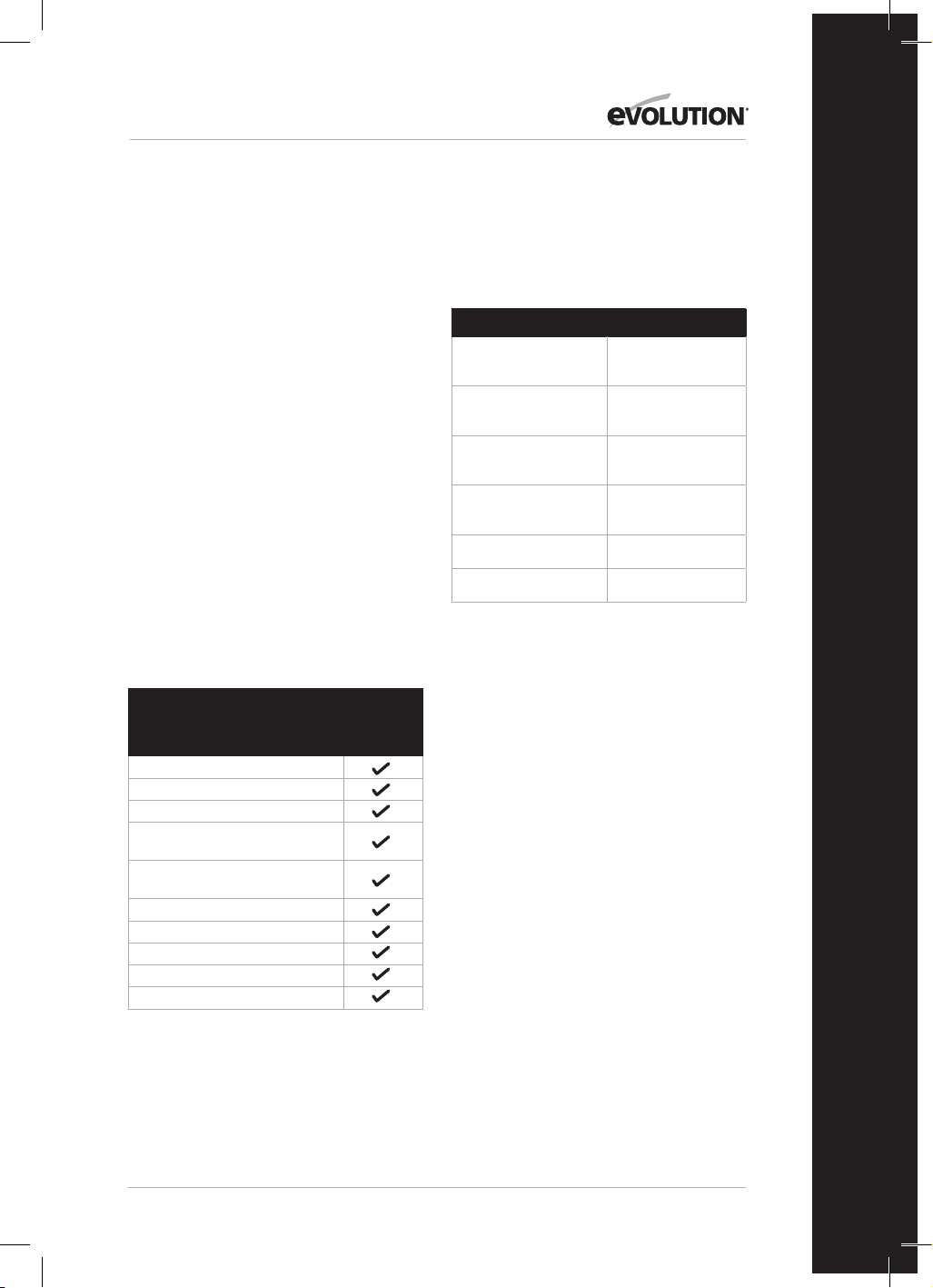
ITEMS SUPPLIED
Description
116-0001,
116-0002,
116-0003,
116-0004
Instruction Manual
Hold Down Clamp
Push Stick
Pin Spanner
(Blade Change)
Double ended hex key 6-5mm
Multi-Purpose Blade
Rip Fence
Dust bag
Table saw guard
Base side extensions x 2
ADDITIONAL ACCESSORIES
In addition to the standard items supplied with
this machine the following accessories are also
available from the Evolution online shop at
www.evolutionpowertools.com or from your
local retailer.
Description Part No
RAGE Multi-Material
TCT Blade
RAGEBLADE210MULTI
210mm General
wood blade
GW210TCT-30
210mm Fine
wood blade
FW210TCT-40
210mm
Diamond blade
D210CON
Mitre saw stand 005-0001
Mitre saw stand + 005-0005

10
www.evolutionpowertools.com
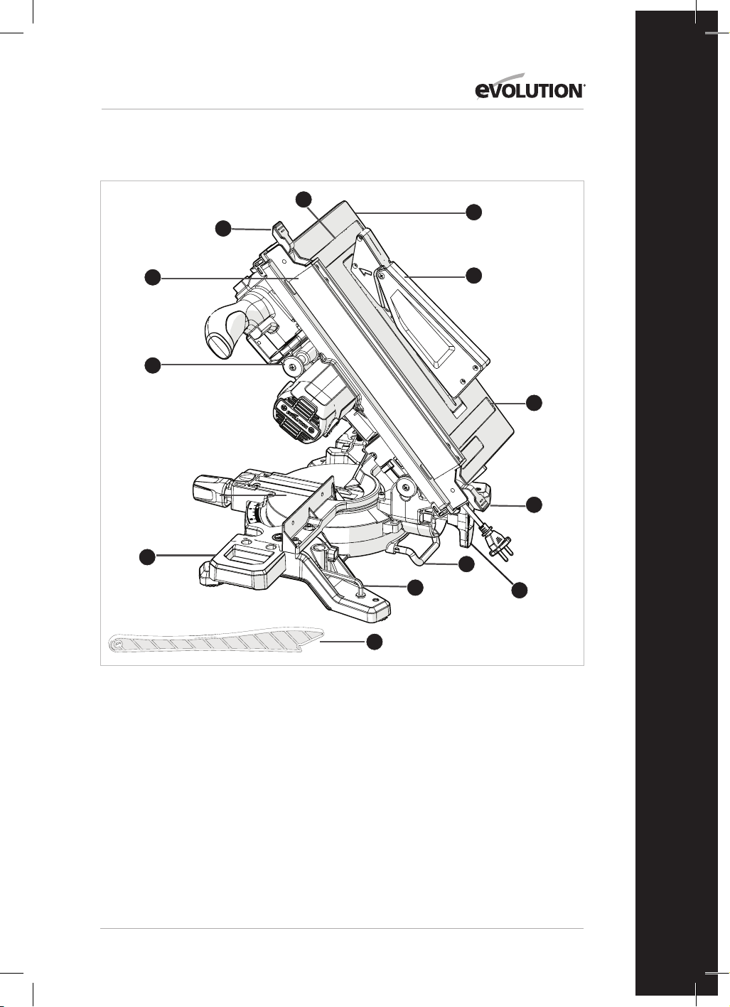
R210MTS-G2 MACHINE OVERVIEW
1
3
8
1. CUTTING HANDLE
2. ROTARY TABLE
3. RETRACTABLE LOWER BLADE GUARD
4. MITRE ANGLE LOCKING HANDLE
5. MITRE ANGLE SCALE
6. CUTTING HEAD RELEASE LEVER
7. CUTTING HEAD LOCK DOWN PIN
8. PUSH STICK STORAGE
9. TABLE SAW ON/OFF SWITCH
10. MITRE SAW ON/OFF TRIGGER
2
9
10
4
6
5
7

11
www.evolutionpowertools.com
EN
R210MTS-G2 MACHINE OVERVIEW
1. TABLE TOP
2. TABLE SAW GUARD
3. RIP FENCE
4. PUSH STICK
5. TABLE/MITRE MODE PIN
6. BEVEL LOCKING LEVER
7. REAR STABILISING ARM
8. WORKPIECE SUPPORTS (X2)
9. TOOL STORAGE
10. RIP FENCE LOCKING LEVERS (X2)
11. TABLE TOP SCALES
2
4
3
1
7
8
9
5
6
10
10
11
11

12
www.evolutionpowertools.com
GETTING STARTED
WARNING: ALWAYS DISCONNECT THE SAW FROM THE POWER
SOURCE BEFORE MAKING ANY ADJUSTMENTS.
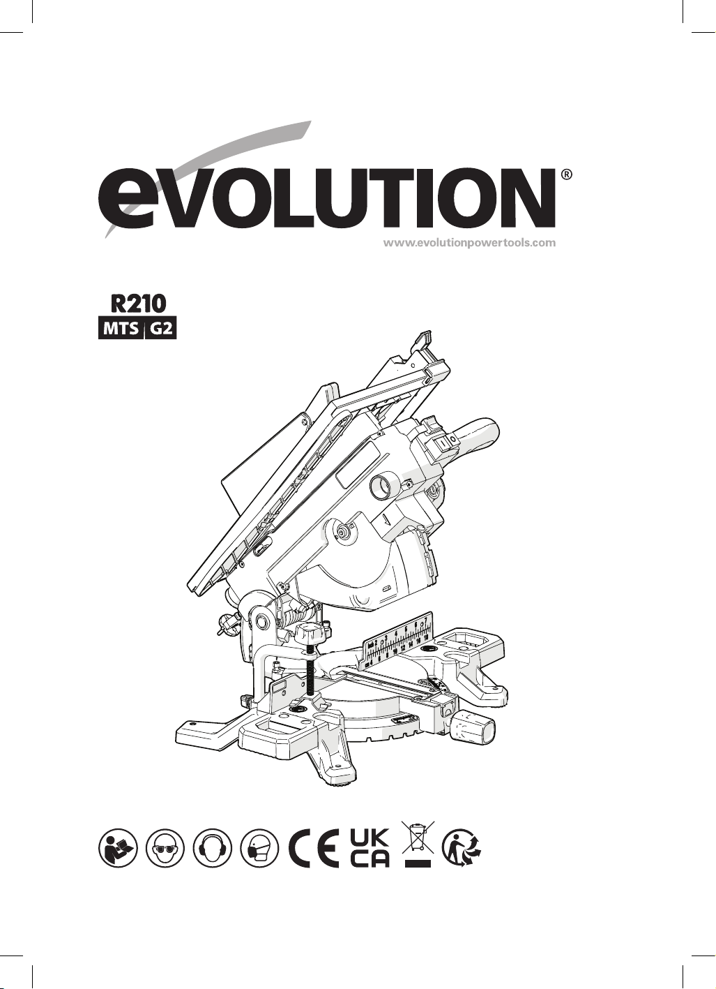
PERMANENTLY MOUNTING THE R210MTS-G2
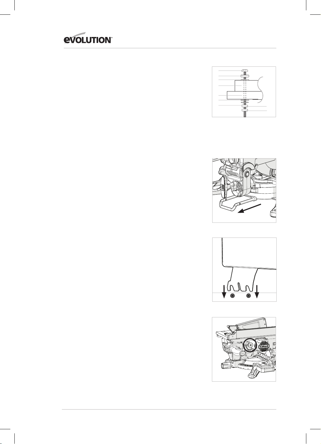
TABLE/MITRE SAW (Fig. 1)
WARNING: To reduce the risk of injury from unexpected saw
movement, place the saw in the desired location either on a
workbench or other recommended leg set. The base of the saw
has four holes to mount the mitre saw. If the saw is to be used in
one location, permanently fasten it to the workbench or leg set
using appropriate bolts with lock washers and nuts.
1. Tighten the mitre and bevel locks.
2. Position the saw so other people cannot stand behind it.
Thrown debris could injure people in its path.
3. Place the saw on a firm, level surface where there is plenty of
room for handling and properly supporting the workpiece.
4. Support the saw so that the table is level and the saw does
not rock.
5. Bolt or clamp the saw to its support.
REAR STABALISING BAR
Extend bar to the rear of the machine (Fig. 2)
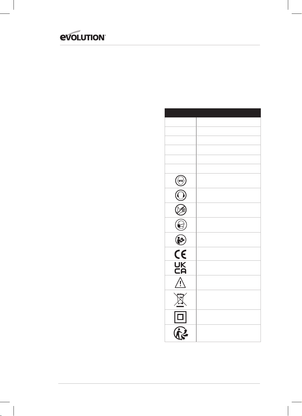
TABLE SAW GUARD
To fit the table saw guard:
• Using the hex key loosen the 2 hex screws
• Fit the table saw guard assembly (Fig.3)
• Tighten the 2 hex screws
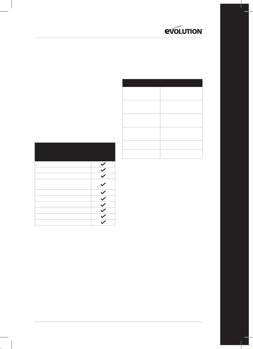
INSTALLING/REMOVING BLADE
WARNING: Only use genuine Evolution blades which are
designed for use in this machine. Ensure that the maximum
speed of the blade is compatible with the machine. Only
perform this operation with the machine disconnected from
the mains supply.
Note: It is recommended that the operator considers wearing
protective gloves when handling the blade during installation
or when changing the machines blade.
To change a blade:
• Pull out pin (Fig. 4) to release the motor.
• Slightly push down on the cutting head handle.
• Pull out the cutting head latching pin and allow the cutting
head to rise to its upmost position. (Fig. 5)
• Use the pin spanner (provided) to hold the outer blade flange.
• Use the hex key (provided) to unscrew the arbor screw. (Fig. 6)
Fig. 1
1) Hex headed bolt
2) Spring washer
3) Flat washer
4) Mitre saw base
5) Workbench
6) Flat washer
7) Spring washer
8) Hex nut
9) Lock nut
(1)
(2)
(3)
(4)
(5)
(6)
(7)
(8)
(9)
Fig. 2
Fig. 4
Fig. 3

13
www.evolutionpowertools.com
EN
Note: The arbor screw has a Left Hand thread. Turn clockwise to
undo and counterclockwise to tighten.
• Remove the arbor screw and outer blade flange.
• Retract the lower blade guard by pressing cutting head
release lever and rotate lower guard upwards exposing the
blade.
• Remove the blade by withdrawing it outwards to clear the
end of the arbor and then downwards and forwards away
from the machine. (Fig.7)
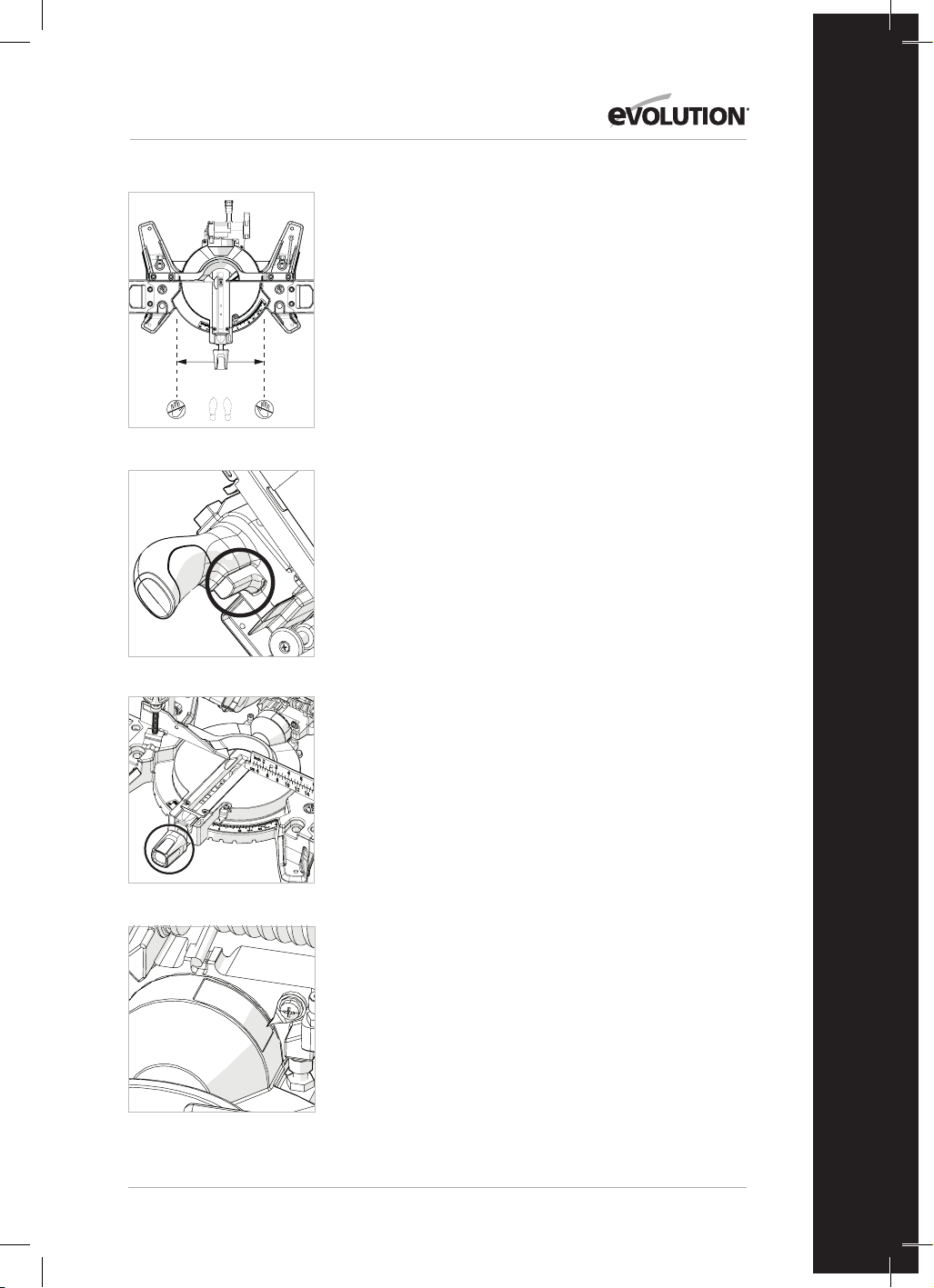
Riving Knife
The Riving Knife is a very important component and comes
fitted to the upper blade guard. The Riving Knife prevents the
work from binding as it passes through the blade. Inspect the
Riving Knife at regular intervals and replace it if it is worn or
damaged.
The Riving Knife should be adjusted so that the gap between
the tips of the blade teeth and the edge of the Riving Knife is
approximately 3-5mm. (Fig. 8)
To adjust the Riving Knife loosen the two fixing screws (Fig. 9)
slightly using an allen key. When correct alignment is achieved
tighten the fixing screws.
Note: Use only a genuine Evolution upper blade guard assembly,
as this is a dedicated component for this machine. Non genuine
parts could be dangerous. If in any doubt, please contact the
Helpline.
TO CONFIGURE THE R210MTS-G2 FOR USE AS A MITRE SAW
WARNING: Only carry out this procedure with the machine
disconnected from the power source.
Caution: The R210MTS-G2 has many built in safety features and
safety interlocks. It is important that the following instructions,
are read, understood and acted upon. Failure to carry out the
configuration procedure could result in damage to the machine
and/or injury to the operator.
• Pull out pin (Fig. 4) to release the motor.
• Slightly push down on the cutting head handle.
• Pull out the cutting head latching pin and allow the cutting
head to rise to its upmost position. (Fig. 5)
The R210MTS-G2 is now ready to use as a mitre saw.
Fig. 5
Fig. 8
Fig. 6
Fig. 7

14
www.evolutionpowertools.com
WORKPIECE SUPPORTS
Workpiece supports must be fitted to both sides of the
machine (Fig.10)
HOLD DOWN CLAMP
A Hold Down clamp is supplied with the R210MTS-G2.
Two sockets (one on either side) are incorporated into the rear
of the machines fence. (Fig. 11)
• Fit the pillar of the clamp into the socket that best suits the
cutting application, ensuring that it is pushed fully down.
• Tighten the fence thumbscrew to lock the pillar of the hold
down clamp into the fence socket.
• Put the workpiece onto the rotary table and against the
fence.
• Adjust the hold down clamp so that it securely holds the
workpiece to the rotary table.
• Before attempting any cutting check to ensure that the
clamp does not interfere with the blade path as the cutting
head is lowered.
OPERATING INSTRUCTIONS MITRE SAW CONFIGURATION
1. Releasing the Cutting Head
Note: When configured in mitre saw mode the cutting head
will be automatically locked in its upper position with the
retractable lower blade guard completely covering the blade
teeth.
To release the cutting head press and hold the cutting head
release lever. (Fig. 12)
Gently press down on the cutting head handle to lower the
cutting head. The operation of the retractable lower blade
guard is automatic, when in contact with the workpiece.
2. Body and Hand position (Fig. 13)
• Never place hands within the ‘no hands zone’ (at least
150mm away from the blade). Pictograms on the machines
rotary table are provided as an aid to safe working practices.
Keep hands away from the path of the blade.
• Hold the workpiece firmly to the fence to prevent any
movement. Use a hold down clamp if possible but check
that it is positioned that it does not interfere with the path
of the blade or other moving machine parts.
• Before attempting a cut, make a ‘dry run’ with the power off
so that you can see the path of the blade.
• Keep hands in position until the ON/OFF trigger has been
released and the blade has completely stopped.
Fig. 11
Fig. 12
Fig. 10
Fig. 9
15
www.evolutionpowertools.com
EN
Fig. 13
3. The Mitre Saw On/Off Trigger Switch Operation
Operate the switch to turn on the machines motor. Release the
switch to turn off the machines motor. (Fig. 14)
4. Chop Cutting
The Cutting Head is gently pushed down to cut through
the workpiece.
• Place the workpiece on the Rotary Table and against the
fence in the desired position. Secure with clamp(s) as
appropriate.
• Grasp the cutting Handle.
• Turn on the motor using the trigger switch and allow the
blade to reach full operating speed.
• Press and hold the cutting head Release Lever to release the
cutting head.
• Gently lower the cutting head to its lowest position,
cutting through the workpiece.
• After the cut is completed, turn off the motor by releasing
the trigger switch. Allow the blade to come to a complete
stop. Allow the cutting head to rise to its upper position.
• Only remove your hands or the workpiece from the machine
when the cutting head is in its upper position with the blade
teeth completely covered by the retractable blade guard.
5. Mitre Cutting
Any angle from 46˚ left to 46˚ right is available, and a
protractor scale can be found to the front of the rotary table.
Positive stops are provided for 0˚, 15˚, 22.5˚, 31.6˚ & 45˚ left and
right of angular movement.
Note: The rotary table must always be locked into position
with the Mitre Angle Locking handle even if a positive stop is
selected.
To select a Mitre Angle:
• Loosen the mitre angle locking handle. (Fig.15)
• Turn the rotary table to the required angle.
• Tighten the mitre angle locking handle securely when the
desired angle has been selected.
A mitre cut can now be made using the same techniques as
previously described in chop cutting.
6. Bevel Cutting
The cutting head can be set at any angle up to 47˚ to the left
hand side only.
The bevel locking lever is found at the rear of the machine.
A protractor guide and pointer are incorporated into the bevel
mechanism to aid setting. (Fig.16)
No-Hands ZoneNo-Hands Zone
Fig. 14
Fig. 15
Fig. 16

16
www.evolutionpowertools.com
To set a Bevel Angle:
• Loosen the bevel lock handle
• Tilt the cutting head to the desired angle. Use the protractor
guide to aid with setting.
• Ensure that the bevel lock handle is securely tightened
when the desired angle has been achieved.
A bevel cut can now be made using the same techniques as
previously outlined.
Note: Always make a ‘dry run’ with the machine switched ‘off’
so that the path of the blade can be checked. Some bevel
and compound cuts may require the hold down clamp to be
positioned to the RH side of the cutting head. This may be
necessary to avoid interference with the blade and other parts
of the machine as the cutting head is lowered.
7. Compound Cutting
A compound cut is a combination of a mitre cut and bevel cut.
• Set the mitre angle required as previously described.
• Set the bevel angle as previously described.
• Ensure the tightness of all adjustment/locking screws, and
conduct a ‘dry run’ to check the path of the blade.
• Make the cut as previously described.
8. Clearing Jammed Material
• Turn mitre saw “OFF” and allow the blade to come to a
complete halt.
• If possible allow the cutting head to rise to its upper
position.
• Unplug the mitre saw from the mains supply.
• Carefully remove any jammed material from the machine.
TO CONFIGURE THE R210MTS-G2 FOR USE AS A TABLE SAW
WARNING: Do not cut metal or metallic materials when the
machine is configured as a table saw.
WARNING: Only carry out this procedure with the machine
disconnected from the power supply.
• Ensure that the Rotary Table is set at 0˚ Mitre angle and the
cutting head is set at 0˚ Bevel angle.
• Lower the cutting head to the fully down position. Push the
cutting head latching pin into its socket. (Fig. 17)
• Retract motor latching pin and rotate motor upwards.
(Fig. 18)
The R210MTS-G2 is now ready to use as a Table Saw. (Fig. 19)
Fig. 18
Fig. 17
Fig. 19

17
www.evolutionpowertools.com
EN
FENCE ASSEMBLY AS A RIP FENCE
To use the Fence Assembly as a Rip Fence the Face Plate must
be accurately aligned with the blade.
WARNING: Only carry out this procedure with the machine
disconnected from the power supply.
To Align the Rip Fence:
• Set the bevel to 0˚ using the table measurement scales.
• Align the fence using the table top scales and lock in place
with the 2 locking levers.
BASIC TABLE SAW OPERATIONS
WARNING: Do not cut metal or metallic materials when the
machine is configured as a Table Saw.
WARNING: Never attempt freehand cuts on this machine.
Always use a correctly adjusted Rip Fence to minimise the
possibility of the blade binding and kickback.
WARNING: This machine is not suitable for cutting rebates or
stopped grooves.
Note: A workshop dust extraction device can be connected
to the extraction port found at the front left hand side of the
machine if required.
1. Table Saw On/Off Switches (Fig. 20)
• Push the Green (I) button to start the motor.
• Push the Red (O) button to stop the motor.
2. Rip cutting
Note: Check that the Rip Fence is locked in position and is
parallel to the saw blade. Check that the riving knife is properly
aligned with the saw blade.
When ripping small section material a Push Stick should be
used to feed/guide the final 300mm of the material past the
blade. A Push Stick should always be used when making cuts
of less than 300mm.
Note: A Push Stick is provided with the R210MTS-G2 and has a
dedicated storage position to the front of the machine.
We recommend that when not in use the Push Stick is stored
on the machine. (Fig.21)
When ripping long boards or large panels always use a remote
work support or enlist competent trained help.
Hands should never be in line with the blade.
Note: If the push stick becomes damaged it should be
replaced.
Fig. 20
Fig. 21

18
www.evolutionpowertools.com
CHECKING AND SETTING OF BEVEL ANGLES
WARNING: Before making any adjustments ensure that the
machine is disconnected from the power supply.
Note: While all angular settings have been factory set,
checking and adjustment may be required as a consequence of
normal operational wear and tear.
Note: To check and adjust the bevel angles the machine must
be in mitre saw configuration.
0˚ BEVEL ANGLE
At 0˚ Bevel Angle the blade should be perpendicular and at
exactly 90˚ to the Rotary Table. An accurate engineers square
(not supplied) is needed to check the 0˚ Bevel Angle.
To check:
• Ensure that the cutting head is in the vertical position,
against its stop with the bevel pointer indicating 0˚ bevel
angle.
• Tighten the bevel lock handle.
• Lower the cutting head to its lowest position. Lock in place
using head locking pin and manually raise lower blade
guard.
• The engineers square can now be used to check the angle
between the blade and the rotary table.
If adjustment is required:
Note: The cutting head will need to be tilted to gain access to
the 0˚ bevel stop adjustment screw.
• Loosen slightly the 0˚ bevel stop adjustment screw locknut.
(Fig. 22)
• Use an allen key to turn the bevel stop screw clockwise or
counterclockwise as required.
• When exact alignment between the
blade and rotary table is achieved, tighten the locknut.
45˚ BEVEL ANGLE
The 45˚ bevel angle can be checked in a similar manner to the
0˚ bevel angle. An accurate 45˚ engineers set square
(not supplied) will be required.
To check:
• Ensure that the cutting head is tilted to the 45˚ position,
against its stop, with the bevel pointer indicating
45˚ bevel angle.
• Tighten the bevel lock handle.
• Lower the cutting head to its lowest position. Lock in place
using head locking pin and manually raise lower blade
guard.
• Use the engineers 45˚ set square to check the angle of
between the blade and the rotary table.
Fig. 22

19
www.evolutionpowertools.com
EN
If adjustment is required:
Note: The Cutting Head will need to be tilted to gain access to
the 45˚ Bevel Stop Adjustment Screw.
• Loosen slightly the 45˚ Bevel Stop Adjustment Screw
locknut. (Fig. 23)
• Use a Hex Key to turn the Bevel Stop Screw clockwise or
counterclockwise as required.
• When exact alignment between the blade and Rotary Table
is achieved, tighten the locknut.
FENCE ADJUSTMENT (Fig. 24a & 24b)
The Fence is fastened to the machines base by four socket
head screws, two on either side. These Screws are located in
elongated holes, which enable the Fence to be repositioned as
required.
The Fence should be set at exactly 90˚ to a correctly installed
blade. An accurate Engineers Square (not supplied) will be
required to precisely position the Fence.
To reposition the Fence:
• Set the Rotary Table to 0˚ Mitre Angle.
• Set the Cutting Head to 0˚ Bevel Angle.
• Slightly loosen the four Fence socket head screws.
• Lower the Cutting Head to its lowest position.
• Check the alignment of the Fence with the Blade using the
Engineers Square.
• Align the Fence as necessary and then tighten the socket
head screws.
MAINTENANCE AND ADJUSTMENTS
WARNING: Ensure that the machine is disconnected from
the mains supply before any maintenance tasks or adjustments
are attempted.
Cleaning
After each use the machine should be cleaned. Remove all
sawdust etc from the visible parts of the machine with a
vacuum cleaner. A vacuum cleaner can also be connected to
the machine dust extraction port at the rear of the machine.
This should remove debris from the inside of the machine.
Never use solvents to clean plastic parts, as solvents can
damage them. Clean only with a soft slightly damp cloth.
In order to extend the service life of the tool, oil the rotary
parts once monthly. Do not oil the motor. When cleaning the
plastic do not use corrosive products.
WARNING: Water must never come into contact with the tool.
ENVIRONMENTAL PROTECTION
Waste electrical products should not be disposed of with
household waste. Please recycle where facilities exist. Check
with your Local Authority or retailer for recycling advice.
Fig. 23
Fig. 24a
Fig. 24b
20
www.evolutionpowertools.com
EC DECLARATION OF CONFORMITY
The manufacturer of the product covered by this Declaration is:
UK: Evolution Power Tools Ltd. Venture One, Longacre Close, Holbrook Industrial Estate, Sheeld, S20 3FR.
FR: Evolution Power Tools SAS. 61 Avenue Lafontaine, 33560, Carbon-Blanc, Bordeaux, France.
The manufacturer hereby declares that the machine as detailed in this declaration fulls all the relevant
provisions of the Machinery Directive and other appropriate directives as detailed below.
The manufacture further declares that the machine as detailed in this declaration, where applicable,
fulls the relevant provisions of the Essential Health and Safety requirements.
The Directives covered by this Declaration are as detailed below:
2006/42/EC. Machinery Directive.
2014/30/EU. Electromagnetic Compatibility Directive
The Restriction of the Use of certain Hazardous
Substances in Electrical Equipment (RoHS) Directive
2012/19/EU. The Waste Electrical and Electronic Equipment (WEEE) Directive.
And is in conformity with the applicable requirements of the following documents:
EN 61029-1:2009+A11• EN 61029-2-11:2012+A11• EN 55014-1:2017+A11:2020 •
EN IEC 55014-1:2021 • EN IEC 55014-2:2021 • EN IEC 61000-3-2:2019+A1 •
EN IEC 61000-3-11:2019
EC type approval to 2006/42/EC Article 12 Section 3b Machinery
Notied Body: TÜV Rheinland LGA Products GmbH - Tillystraße 2 - 90431 Nürnberg
Notied Body No.: 0197 Reg. No.: BM 50592380 0001
Product Details
Description: R210MTS G2 210mm MULTI-MATERIAL TABLE/MITRE SAW
Evolution Model No: 116-0001, 116-0002, 116-0003, 116-0004
Brand Name: EVOLUTION
Voltage: 220-240V~ 50Hz
Input: 1500W
The technical documentation required to demonstrate that the product meets the requirements
of directive has been compiled and is available for inspection by the relevant enforcement
authorities, and veries that our technical le contains the documents listed above and that they
are the correct standards for the product as detailed above.
Name and address of technical documentation holder.
Signed: Print: Barry Bloomer
Supply Chain & Procurement Director
Date: 08/02/22
UK: Evolution Power Tools Ltd. Venture One, Longacre Close, Holbrook Industrial Estate, Sheeld, S20 3FR.
FR: Evolution Power Tools SAS. 61 Avenue Lafontaine, 33560, Carbon-Blanc, Bordeaux, France.
2011/65/EU. &
2015/863/EU.
21
www.evolutionpowertools.com
EN
EC DECLARATION OF CONFORMITY
The manufacturer of the product covered by this Declaration is:
UK: Evolution Power Tools Ltd. Venture One, Longacre Close, Holbrook Industrial Estate, Sheeld, S20 3FR.
FR: Evolution Power Tools SAS. 61 Avenue Lafontaine, 33560, Carbon-Blanc, Bordeaux, France.
The manufacturer hereby declares that the machine as detailed in this declaration fulls all the relevant
provisions of the Machinery Directive and other appropriate directives as detailed below.
The manufacture further declares that the machine as detailed in this declaration, where applicable,
fulls the relevant provisions of the Essential Health and Safety requirements.
The Directives covered by this Declaration are as detailed below:
UK legislation_Supply of Machinery (Safety) Regulations 2008;
UK legislation_Electromagnetic Compatibility Regulations 2016;
UK legislation _The Restriction of the Use of Certain Hazardous Substances in Electrical and
Electronic Equipment Regulations 2012
And is in conformity with the applicable requirements of the following documents:
BS EN 61029-1:2009+A11• BS EN 61029-2-11:2012+A11 • BS EN IEC 55014-1:2021 •
BS EN IEC 55014-2:2021 • BS EN IEC 61000-3-2:2019+A1 • BS EN IEC 61000-3-11:2019
Type-examination UK Regulations SI 2008 No. 1597
Notied Body: TUV Rheinland UK Ltd. – Friars Gate (Third Floor), 1011 Stratford Road, Shirley, Solihull, B90 4BN
Notied Body No.: 8400 Reg. No.: A6 50541548 0001
Product Details
Description: R210MTS G2 210mm MULTI-MATERIAL TABLE/MITRE SAW
Evolution Model No: 116-0001, 116-0002, 116-0003, 116-0004
Brand Name: EVOLUTION
Voltage: 220-240V~ 50Hz
Input: 1500W
The technical documentation required to demonstrate that the product meets the requirements
of directive has been compiled and is available for inspection by the relevant enforcement
authorities, and veries that our technical le contains the documents listed above and that they
are the correct standards for the product as detailed above.
Name and address of technical documentation holder.
Signed: Print: Barry Bloomer - CEO
Date: 08/02/22
UK: Evolution Power Tools Ltd. Venture One, Longacre Close, Holbrook Industrial Estate, Sheeld, S20 3FR.
FR: Evolution Power Tools SAS. 61 Avenue Lafontaine, 33560, Carbon-Blanc, Bordeaux, France.

22
www.evolutionpowertools.com
WICHTIG
Lesen Sie diese Betriebs- und
Sicherheitsanweisungen bitte sorgfältig und
vollständig durch.
Sollten Sie sich hinsichtlich der Anwendung des
Elektrowerkzeugs unsicher fühlen, kontaktieren
Sie zu Ihrer eigenen Sicherheit unsere technische
Helpline, deren Nummer auf der Website von
Evolution Power Tools zu finden ist.
Wir bieten weltweit eine Vielzahl von Helplines
an. Technische Hilfe ist jedoch auch über Ihren
Einzelhändler verfügbar.
INTERNET
www.evolutionpowertools.com
E-MAIL
UK:customer[email protected]
USA: evolutioninfo@evolutionpowertools.com
GARANTIE
Wir gratulieren Ihnen zum Kauf einer Maschine
von Evolution Power Tools. Folgen Sie den
Anweisungen des beliegenden Merkblattes und
registrieren Sie Ihr Produkt „online“. Hierdurch
aktivieren Sie die Garantiefrist Ihrer Maschine
über die Evolution-Website. Geben Sie zu diesem
Zweck einfach Ihre Kontaktdaten ein und sichern
Sie sich einen schnellen Kundenservice, wann
immer Sie ihn brauchen.
Wir danken Ihnen, dass Sie sich für ein Produkt
von Evolution Power Tools entschieden haben.
Evolution Power Tools behält sich das Recht
vor, ohne vorherige Mitteilung konstruktive
Verbesserungen und Änderungen am Produkt
vorzunehmen.
Die Garantiebedingungen nden Sie auf dem
Merkblatt zur Garantieregistrierung und/oder der
Verpackung.

23
www.evolutionpowertools.com
DE
TECHNISCHE DATEN
MASCHINE GB/EU
Motor (220–240 V ~ 50Hz) 1500W
Leerlaufgeschwindigkeit 3800 min
-1
Gewicht 13kg
SCHNITTLEISTUNG GB/EU
Baustahlplatte - max. Stärke 3mm
Baustahlplatte - max. Stärke 210HB
MAXIMALE SCHNITTLEISTUNG (ALUMINIUM, HOLZ UND PVC)
KONFIGURATION DER GEHRUNGSSÄGE
GEHRUNG NEIGUNG GB/EU
0° 0° 55 x 120mm
45° 0° 35 x 120mm
0° 45° Links 55 x 65mm
0° 45° Rechts 55 x 55mm
45° 45° Links 35 x 30 mm
45° 45° Rechts 35 x 70mm
MAXIMALE SCHNITTLEISTUNG - KONFIGURATION DER TISCHKREISSÄGE
SCHNITTLEISTUNG UK/EU
Holz - max. Stärke 40mm
SÄGEBLATTABMESSUNGEN UK/EU
Durchmesser 210mm
Bohrung 25.4mm
Anzahl der Zähne 20
Schnittfuge 1.7mm
LÄRM- UND VIBRATIONSBEZOGENE DATEN
Schalldruck L
P
A 103 dB(A); K=3 dB(A)
Schallleistungspegel L
W
A 116 dB(A); K=3 dB(A)

24
www.evolutionpowertools.com
Die angegebenen Geräuschemissionswerte
wurden im Einklang mit einer Standard-
Prüfmethode (EN61029-1, EN61029-2-11)
gemessen und können verwendet werden,
um verschiedene Maschinen miteinander zu
vergleichen.
WARNUNG: Die Geräuschemissionen, die
bei der Verwendung des Elektrowerkzeugs
entstehen, können von den angegebenen
Gesamtwerten abweichen, je nachdem, wie
das Werkzeug eingesetzt wird und welche Art
von Werkstücken bearbeitet wird.
Es ist notwendig, Sicherheitsmaßnahmen
zum Schutz des Bedieners festzulegen, die
auf einer Abschätzung der Exposition unter
den tatsächlichen Einsatzbedingungen
beruhen (unter Berücksichtigung aller Teile
des Betriebszyklus wie z.B. der Zeiten, in
denen das Werkzeug ausgeschaltet ist und im
Leerlauf läuft, zusätzlich zur Auslösezeit)
KENNZEICHNUNGEN UND SYMBOLE
WARNUNG: Verwenden Sie die Maschine
nicht, wenn Warnhinweise und/oder
Hinweisschilder fehlen oder beschädigt sind.
Für Ersatz wenden Sie sich an Evolution Power
Tools.
Hinweis: Manche oder alle der
folgenden Symbole können in der
Originalbetriebsanleitung oder auf dem
Produkt abgebildet sein.
Symbol Beschreibung
V
Volt
A
Ampere
Hz
Hertz
Min
-1
Drehzahl
~
Wechselstrom
n
o
Leerlaufdrehzahl
Schutzbrille tragen
Gehörschutz tragen
Nicht berühren
Staubschutz tragen
Anleitung lesen
CE-Zertifizierung
UKCA-Zertifizierung
Warnung
Entsorgung als Elektro-
und Elektronikschrott
Doppelt isoliert
Triman - Restmüllabfuhr
& Recycling

25
www.evolutionpowertools.com
DE
BESTIMMUNGSGEMÄSSER GEBRAUCH DES
ELEKTROWERKZEUGS
WARNUNG: Dieses Produkt ist eine von
Hand betriebene Kapp- und Gehrungssäge
und wurde für den Einsatz mit speziellen
Evolution-Sägeblättern entwickelt. Verwenden
Sie ausschließlich für den Gebrauch mit dieser
Maschine entwickeltes und/oder ausdrücklich von
Evolution Power Tools Ltd empfohlenes Zubehör.
Mit geeignetem Sägeblatt kann diese Maschine
zum Schneiden der folgenden Materialien
verwendet werden:
Baustahl
Aluminium
Holz
Kunststoffe
UNZULÄSSIGER GEBRAUCH DIESES
ELEKTROWERKZEUGS
WARNUNG: Dieses Produkt ist eine von Hand
betriebene Kapp- und Gehrungssäge und darf
nur bestimmungsgemäß verwendet werden. Es
dürfen keinerlei Modifikationen vorgenommen
werden. Weiterhin darf die Maschine nicht mit
anderer Ausrüstung oder anderem Zubehör als
dem in dieser Betriebsanleitung erwähntem in
Betrieb genommen werden.
WARNUNG: Diese Maschine ist nicht bestimmt
zur Nutzung von Personen (einschließlich
Kindern) mit eingeschränkten körperlichen,
sensorischen bzw. geistigen Fähigkeiten,
mangelnder Erfahrung bzw. fehlendem Wissen,
sofern diese nicht durch eine für ihre Sicherheit
verantwortliche Person beaufsichtigt werden
bzw. Anweisungen für die sichere Nutzung der
Maschine erhalten haben.
Kinder müssen beaufsichtigt werden, um
sicherzustellen, dass sie keinen Zugang zu der
Maschine haben und nicht mit ihr spielen.
ELEKTRISCHE SICHERHEIT
Diese Maschine ist ausgestattet mit dem auf
dem Zielmarkt jeweils verwendeten Stecker
und Anschlusskabel. Bei Beschädigung des
Anschlusskabels ist dieses durch ein vom
Hersteller oder dessen Händler zur Verfügung
gestelltes Kabel zu ersetzen.
VERWENDUNG IM FREIEN
WARNUNG: Zu Ihrer eigenen Sicherheit sollte
diese Maschine bei der Verwendung im Freien
nicht Regen ausgesetzt werden und nicht in einer
feuchten Umgebung betrieben werden.
Stellen Sie das Werkzeug nicht auf feuchte
Oberflächen.
Verwenden Sie eine saubere, trockene Werkbank,
falls verfügbar.
Verwenden Sie für zusätzlichen Schutz eine
Fehlerstrom-Schutzeinrichtung (R.C.D.), die
bei Leckstrom von über 30 mA über einen
Zeitraum von 30 ms die Stromzufuhr unterbricht.
Überprüfen Sie immer die Funktion der
Fehlerstrom-Schutzeinrichtung, bevor Sie die
Maschine verwenden.
Wenn ein Verlängerungskabel erforderlich ist,
muss es für die Verwendung im Freien geeignet
und entsprechend gekennzeichnet sein. Bei
Verwendung eines Verlängerungskabels sind die
Anweisungen des Herstellers zu beachten.
ALLGEMEINE SICHERHEITSANWEISUNGEN
FÜR ELEKTROWERKZEUGE
• Befolgen Sie alle diese Anweisungen, bevor
und während Sie mit der Säge arbeiten.
• Bewahren Sie diese Anweisungen an einem
sicheren Ort auf.
• Vermeiden Sie Körperkontakt mit
geerdeten Oberflächen.
• Geräte, die nicht in Verwendung sind,
sollten außerhalb der Reichweite
von Kindern an einem trockenen
abgeschlossenen Ort verstaut werden.
• Wenn Sie Ihre Werkzeuge scharf und sauber
halten, können Sie besser und sicherer
arbeiten. Überprüfen Sie das Netzkabel
regelmäßig und lassen Sie es bei den
ersten Anzeichen von Schäden von einem
autorisierten Fachmann austauschen.
• Überprüfen Sie Ihre Verlängerungskabel
regelmäßig und ersetzen Sie diese, wenn
sie beschädigt sind.
• Verwenden Sie bei Arbeiten im Freien
nur Verlängerungskabel, die für
den Außeneinsatz zugelassen und
entsprechend gekennzeichnet sind.
• Konzentrieren Sie sich auf das, was Sie tun.
Gehen Sie mit Bedacht an Ihre Arbeit heran.
Benutzen Sie das Werkzeug nie, wenn Sie
müde sind.
• Verwenden Sie niemals ein Werkzeug mit
einem Schalter, der sich nicht ein- und
ausschalten lässt.
• Vorsicht! Die Verwendung von nicht dafür
vorgesehenen, einsteckbaren Werkzeugen
und Zubehörteilen kann die Gefahr von
Verletzungen bergen.
• Die Maschine ist mit einem
Sicherheitsschalter ausgestattet, der
ein versehentliches Wiedereinschalten
nach einem Stromausfall (im
Tischkreissägenbetrieb) verhindert.
• Verwenden Sie die Säge niemals zum
Schneiden von Rundholz.
• Überprüfen Sie das Netzkabel. Verwenden
Sie niemals ein defektes oder beschädigtes
Netzkabel.
• Verwenden Sie das Kabel nicht, um den
Stecker aus der Steckdose zu ziehen.

26
www.evolutionpowertools.com
Schützen Sie das Kabel von Hitze, Öl und
scharfen Kanten.
• Wir empfehlen bei der Arbeit im Freien das
Tragen von rutschfesten Schuhen.
• Lange Haare in einem Haarnetz verwahren.
• Vermeiden Sie eine unnatürliche
Arbeitshaltung.
• Ein unaufgeräumter Arbeitsbereich kann zu
Unfällen führen.
• Erlauben Sie es anderen Personen,
insbesondere Kindern, nicht, das Gerät oder
das Netzkabel zu berühren. Halten Sie diese
von Ihrem Arbeitsplatz fern.
• Der Spaltkeil ist eine wichtige
Sicherheitseinrichtung. Er führt nicht nur
das Werkstück, sondern verhindert auch,
dass sich die Schnittfuge hinter der Klinge
schließt, sodass es keinen Rückschlag vom
Werkstück gibt. Achten Sie auf die Dicke
des Spaltkeils. Der Spaltkeil sollte niemals
dünner als der Sägeblattkörper oder dicker
als die Breite der Schnittfuge sein.
• Der obere Sägeblattschutz muss für
jeden Schnitt über das Werkstück gesenkt
werden.
• Verwenden Sie unbedingt einen
Schiebestock, wenn Sie schmale Werkstücke
mit einer Breite von weniger als 120mm
schneiden, oder einen Schiebeblock, wenn
Sie schmale Werkstücke mit einer Breite von
weniger als 30mm schneiden.
WICHTIG: Verwenden Sie diese Säge niemals für
Aufsetzschnitte.
• Stellen Sie sich beim Arbeiten mit der
Gehrungssäge immer seitlich vom
Sägeblatt auf.
• Achten Sie darauf, dass Schnittabfälle nicht
am Sägeblattkranz hängen bleiben, da
sie sonst in die Umgebung geschleudert
werden können.
• Ist der Sägespalt verschlissen, tauschen Sie
die Tischeinlage aus.
• Um Verletzungen durch umherfliegende
Sägespäne zu vermeiden, verwenden Sie
die Säge nur mit einer entsprechenden
Absauganlage oder einem handelsüblichen
Industriestaubsauger.
• Ziehen Sie immer den Netzstecker aus
der Steckdose, bevor Sie die Maschine
einstellen oder warten.
• Geben Sie diese Sicherheitshinweise an
alle Personen weiter, die an der Maschine
arbeiten.
• Verwenden Sie diese Säge nicht zum
Schneiden von Brennholz.
• Vorsicht! Durch das rotierende Sägeblatt
können Hände und Finger verletzt werden.
• Vergewissern Sie sich vor der ersten
Inbetriebnahme der Maschine, dass die auf
dem Typenschild angegebene Spannung
mit der Netzspannung übereinstimmt.
• Wenn Sie ein Verlängerungskabel
verwenden müssen, vergewissern Sie
sich, dass dessen Leiterquerschnitt für die
Leistungsaufnahme der Säge ausreicht.
Mindestquerschnitt: 1,0 mm
2
.
• Bei Verwendung einer Kabeltrommel
muss das gesamte Kabel von der Trommel
abgezogen werden.
• Tragen Sie die Säge niemals an deren Kabel.
• Lassen Sie die Säge nicht im Regen stehen
und benutzen Sie sie nicht in feuchter oder
nasser Umgebung.
• Sorgen Sie für eine gute Beleuchtung.
• Nicht in unmittelbarer Nähe von
brennbaren Flüssigkeiten oder Gasen
sägen.
• Tragen Sie geeignete Arbeitskleidung. Lose
Kleidungsstücke oder Schmuck können sich
in dem rotierenden Sägeblatt verfangen.
• Das Bedienpersonal muss mindestens
18 Jahre alt sein. Auszubildende, die
mindestens 16 Jahre alt sind, dürfen die
Maschine nur unter Aufsicht benutzen.
• Achten Sie darauf, dass Kinder nicht in die
Nähe der Maschine kommen, wenn diese
an das Stromnetz angeschlossen ist.
WICHTIG:
• Überprüfen Sie das Netzkabel. Verwenden
Sie niemals ein defektes oder beschädigtes
Netzkabel.
• Halten Sie den Arbeitsbereich sauber von
Holzabfällen und unnötigen Gegenständen.
• Die an der Maschine arbeitenden Personen
sollten nicht abgelenkt werden.
• Achten Sie auf die Drehrichtung von Motor
und Sägeblatt.
• Verlangsamen Sie das Sägeblatt nach dem
Abschalten des Motors niemals durch
seitlichen Druck.
• Setzen Sie nur Sägeblätter ein, die gut
geschärft sind und keine Risse oder
Verformungen aufweisen.
• Die Maschine darf nur mit Werkzeugen
betrieben werden, die der Norm EN847-1
entsprechen.
• Defekte Sägeblätter müssen sofort
ausgetauscht werden.
• Verwenden Sie niemals Sägeblätter, die
nicht den in dieser Anleitung angegebenen
Daten entsprechen.
• Stellen Sie sicher, dass der Pfeil auf dem
Sägeblatt mit dem auf der Maschine
markierten Pfeil übereinstimmt.
• Achten Sie darauf, dass das Sägeblatt in
keiner Stellung den Drehtisch berührt.

27
www.evolutionpowertools.com
DE
Ziehen Sie dazu den Netzstecker und
schwenken Sie das Sägeblatt von Hand
in die 45°- und 90°-Stellung. Stellen Sie
gegebenenfalls den Sägekopf neu ein.
• Achten Sie unbedingt darauf, dass alle
Vorrichtungen zur Abdeckung des
Sägeblattes einwandfrei funktionieren.
• Die aufklappbare Schutzhaube niemals in
geöffneter Stellung festklemmen.
GESUNDHEITSHINWEISE
WARNUNG: Bei Arbeiten mit dieser Maschine
können Staubpartikel entstehen. Abhängig von
den Materialien, mit denen Sie arbeiten, kann
dieser Staub in einigen Fällen besonders schädlich
sein. Wenn Sie den Verdacht haben, dass die Farbe
auf der Oberfläche des zu schneidenden Materials
Blei enthält, wenden Sie sich an einen Fachmann.
Auf Blei basierte Farben sind von professionellen
Fachkräften zu entfernen. Von Selbstversuchen
ist abzuraten. Hat sich der Staub auf Oberflächen
abgesetzt, kann Hand-Mund-Kontakt zur
Aufnahme von Blei führen.
Schon geringe Mengen an Blei können
unwiderrufliche Schäden an Hirn und
Nervensystem verursachen. Kinder und
Jugendliche sowie ungeborene Kinder sind
besonders gefährdet. Es wird empfohlen, die
mit den Materialien, mit denen Sie arbeiten,
verbundenen Risiken zu berücksichtigen und
das Expositionsrisiko zu verringern. Da einige
Materialien gesundheitsschädlichen Staub
erzeugen können, empfehlen wir, wenn Sie dieses
Gerät verwenden, das Tragen einer zugelassenen
Gesichtsmaske mit austauschbaren Filtern.
Sie sollten stets:
• in gut belüfteten Bereichen arbeiten.
• geprüfte Schutzausrüstung tragen,
z.B. eine Staubmaske für die Filterung
mikroskopisch kleiner Partikel.
WARNUNG: Bei der Arbeit mit
Elektrowerkzeugen können Objekte in Richtung
Ihrer Augen geschleudert werden. Dies kann zu
schweren Verletzungen der Augen führen. Tragen
Sie vor Inbetriebnahme des Elektrowerkzeugs
immer eine Sicherheitsbrille oder eine
Schutzbrille mit seitlichem Schutz oder wenn
notwendig einen Gesichtsschutz.
ZUSÄTZLICHE SICHERHEITSHINWEISE -
GEHRUNGSSÄGEN
Die folgenden spezifischen Sicherheitshinweise
für Gehrungssägen richten sich nach
EN61029-2-11
SÄGEBLATT-SICHERHEITSHINWEISE
WARNUNG: Rotierende Kreissägeblätter sind
äußerst gefährlich und können zu schweren
Verletzungen und dem Verlust von Gliedmaßen
führen. Halten Sie Finger und Hände immer
mindestens 150mm vom Sägeblatt entfernt.
Versuchen Sie niemals, das Sägematerial
herauszuholen, bevor der Schneidkopf in
angehobener Position ist, die Schutzvorrichtung
vollständig geschlossen ist und das Sägeblatt sich
nicht mehr dreht.
Verwenden Sie nur Sägeblätter, die vom Hersteller
empfohlen werden und wie in dieser Anleitung
beschrieben und die den Anforderungen der
EN847-1 entsprechen.
Verwenden Sie keine Sägeblätter, die beschädigt
oder verformt sind. Sie könnten brechen und
schwere Verletzungen beim Bediener oder
umstehenden Personen verursachen.
Verwenden Sie keine Sägeblätter aus
Schnellarbeitsstahl (HSS).
Wenn der Tischeinsatz beschädigt oder
abgenutzt ist, muss er durch einen identischen
ersetzt werden, der, wie in diesem Handbuch
beschrieben, vom Hersteller erhältlich ist.
PERSÖNLICHE
SCHUTZAUSRÜSTUNG (PSA)
Gehörschutz sollte getragen werden,
um das Risiko eines induzierten Hörverlusts zu
reduzieren.
Augenschutz sollte getragen werden, um den
Verlust des Augenlichts durch Auswurf von
Splittern zu verhindern.
Ein Atemschutz wird empfohlen, da manche
Holzarten und Holzprodukte, insbesondere
MDF (mitteldichte Holzfaserplatten), potenziell
gesundheitsschädlichen Staub produzieren
können.
Wir empfehlen während der Benutzung der
Maschine die Verwendung von geprüften
Gesichtsschutzmasken mit austauschbaren Filtern
zusammen mit einer Vorrichtung zum Absaugen
von Staub.
Beim Umgang mit Sägeblättern oder rauem
Material sollten Handschuhe getragen werden.
Es wird empfohlen, die Sägeblätter möglichst
in einer Halterung zu tragen. Es ist ratsam,
Handschuhe zu tragen, wenn Sie mit der
Gehrungssäge hantieren.
SICHERER BETRIEB
Überprüfen Sie außerdem immer, ob das
Sägeblatt für das zu schneidende Material
geeignet ist. Verwenden Sie diese Gehrungssäge
nicht zum Schneiden von anderen als den in
dieser Bedienungsanleitung angegebenen
Materialien.

28
www.evolutionpowertools.com
Achten Sie beim Transport der Gehrungssäge
darauf, dass der Schneidkopf in der 90°-Position
nach unten verriegelt ist (bei einer Gleit-
Gehrungssäge, dass die Gleitstangen verriegelt
sind). Heben Sie das Gerät an, indem Sie die
Außenkante des Sockels mit beiden Händen
anfassen (eine Gleit-Gehrungssäge transportieren
Sie mit den dafür vorgesehenen Griffen). Die
Maschine darf unter keinen Umständen an
der einziehbaren Schutzvorrichtung oder
irgendeinem Teil ihres Betriebsmechanismus
angehoben oder transportiert werden.
Überprüfen Sie vor jedem Gebrauch die Funktion
der einziehbaren Schutzvorrichtung und ihres
Betätigungsmechanismus, um sicherzustellen,
dass keine Schäden vorhanden sind und dass
alle beweglichen Teile einwandfrei und korrekt
funktionieren.
Halten Sie die Werkbank und den Bodenbereich
frei von Schmutz, Sägemehl, Spänen und
Abschnitten.
Sie sollten immer überprüfen und
sicherstellen, dass die auf dem Sägeblatt
angegebene Geschwindigkeit mindestens
der auf der Gehrungssäge angegebenen
Leerlaufgeschwindigkeit entspricht.
Auf keinen Fall darf ein Sägeblatt verwendet
werden, dessen Geschwindigkeit unter
der auf der Gehrungssäge angegebenen
Leerlaufgeschwindigkeit liegt.
Wo es erforderlich ist, Distanz - oder
Reduzierringe zu verwenden, müssen diese
für den vorgesehenen Zweck geeignet sein
und dürfen nur gemäß den Empfehlungen des
Herstellers eingesetzt werden.
Das Sägeblatt darf nur wie in dieser
Bedienungsanleitung beschrieben ausgetauscht
werden.
Versuchen Sie niemals, Abschnitte oder andere
Teile des Werkstücks zu entnehmen, bis sich der
Schneidkopf in angehobener Position befindet,
die Schutzvorrichtung vollständig geschlossen ist
und das Sägeblatt sich nicht mehr dreht.
SCHNITTE KORREKT UND SICHER AUSFÜHREN
Wo immer möglich, sichern Sie das Werkstück
mit der Werkstückklemme am Sägetisch, sofern
vorhanden.
Stellen Sie immer sicher, dass die Säge vor jedem
Schnitt stabil montiert ist.
Bei Bedarf kann die Gehrungssäge auf
auf einem Holzsockel oder einer Werkbank
montiert oder an einem Gehrungssägenständer
befestigt werden, wie in dieser Betriebsanleitung
beschrieben.
Lange Werkstücke sollten durch die
bereitgestellten Arbeitshilfen oder auf
entsprechenden zusätzlichen Arbeitshilfen
gestützt werden.
WARNUNG: Sollten Teile fehlen, verwenden Sie
die Maschine nicht, bis die fehlenden Teile ersetzt
wurden. Die Nichtbeachtung dieser Regel kann zu
schweren Verletzungen führen.
ZUSÄTZLICHE SICHERHEITSHINWEISE
DAS TRAGEN IHRER TISCHGEHRUNGSSÄGE
Sicherheitshinweis
• Obwohl kompakt, ist diese Säge schwer.
Um das Risiko von Rückenverletzungen zu
reduzieren, sollten Sie sich beim Anheben der
Säge kompetent helfen lassen.
• Um das Risiko von Rückenverletzungen zu
reduzieren, halten Sie das Werkzeug beim
Anheben nahe an Ihren Körper. Beugen
Sie die Knie, damit Sie mit den Beinen heben
können, nicht mit dem Rücken. Heben Sie die
Säge an den Griffbereichen an beiden Seiten
des Maschinenfußes an.
• Tragen Sie die Tischgehrungssäge niemals
am Netzkabel. Das Tragen des Werkzeugs am
Netzkabel kann zu Schäden an der Isolierung
oder den Kabelverbindungen führen, was
zu einem elektrischen Schlag oder Brand zur
Folge haben kann.
• Bevor Sie die Säge bewegen,
ziehen Sie die Gehrungs- und
Neigungsverriegelungsschrauben fest, um
eine plötzliche unerwartete Bewegung zu
verhindern.
• Verriegeln Sie den Schneidkopf in seiner
untersten Position. Stellen Sie sicher, dass
der Verriegelungsstift des Schneidkopfs
vollständig in der Buchse sitzt.
WARNUNG: Verwenden Sie den Sägeblattschutz
nicht als „Hebepunkt“. Das Netzkabel muss von
der Stromversorgung getrennt werden, bevor Sie
versuchen, das Gerät zu bewegen.
• Sichern Sie den Schneidkopf mit dem
Sicherungsstift des Schneidkopfes in der
unteren Position.
• Lösen Sie die Gehrungswinkel-
Verriegelungsschraube. Drehen Sie den Tisch
auf eine der maximalen Einstellungen.
• Verriegeln Sie den Tisch mit der
Sicherungsschraube in Position.
• Verwenden Sie zum Transport der Maschine
die beiden Griffaussparungen, die auf beiden
Seiten des Maschinenfußes angebracht sind.
29
www.evolutionpowertools.com
DE
Stellen Sie die Säge auf eine sichere, feste
Arbeitsfläche und überprüfen Sie die Säge
sorgfältig.
Überprüfen Sie insbesondere die Funktion aller
Sicherheitsvorrichtungen der Maschine, bevor Sie
die Maschine in Betrieb nehmen.
ERSTE SCHRITTE - AUSPACKEN
Vorsicht: Diese Verpackung enthält scharfe
Gegenstände. Lassen Sie beim Auspacken
Vorsicht walten. Entnehmen Sie die Maschine
sowie das im Lieferumfang enthaltene Zubehör
der Verpackung. Überprüfen Sie sorgfältig,
ob die Maschine in gutem Zustand ist, und
berücksichtigen Sie dabei das gesamte in dieser
Anleitung aufgeführte Zubehör.
Stellen Sie ebenfalls sicher, dass alle Zubehörteile
vollständig sind. Fehlen Teile, geben Sie die
Maschine zusammen mit dem Zubehör in
Originalverpackung beim Einzelhändler ab.
Entsorgen Sie die Verpackung nicht; bewahren Sie
sie während der Garantiefrist sicher auf. Entsorgen
Sie die Verpackung umweltfreundlich. Recyceln
Sie sie nach Möglichkeit. Lassen Sie niemals
Kinder mit leeren Plastiktüten spielen, es besteht
Erstickungsgefahr.
IM LIEFERUMFANG ENTHALTENE TEILE
Beschreibung
116-0001,
116-0002,
116-0003,
116-0004
Betriebsanleitung
Niederhalterklemme
Schubstange
Pin-Spanner
(Wechsel der Sägeblätter)
Doppelendiger
Sechskantschlüssel 6-5mm
Mehrzweck-Sägeblatt
Parallelanschlag
Staubbeutel
Tischsägenschutz
Seitliche Sockelverlängerungen x2
ZUSÄTZLICHES ZUBEHÖR
Neben den im Lieferumfang dieser Maschine
enthaltenen Standardartikeln sind zudem die
folgenden Zubehörteile über den Evolution-
Online-Shop unter
www.evolutionpowertools.com oder bei Ihrem
örtlichen Händler erhältlich.
Beschreibung Teile-Nr.
RAGE Multi-Material
Hartmetallsägeblatt
RAGEBLADE210MULTI
210mm allgemein
Holzsägeblatt
GW210TCT-30
210mm fein
Holzsägeblatt
FW210TCT-40
210mm
Diamantblatt
D210CON
Gehrungssägenständer 005-0001
Gehrungssägenständer + 005-0005

30
www.evolutionpowertools.com
R210MTS-G2 MASCHINENÜBERSICHT
1
3
8
1. SCHNEIDGRIFF
2. DREHTISCH
3. EINZIEHBARER UNTERER
SÄGEBLATTSCHUTZ
4. GEHRUNGSWINKEL-FESTSTELLGRIFF
5. GEHRUNGSWINKELSKALA
6. SCHNEIDKOPF-FREIGABEHEBEL
7. SPERRSTIFT FÜR SCHNEIDKOPF
8. SCHUBSTANGENABLAGE
9. TISCHKREISSÄGE EIN/AUS-SCHALTER
10. GEHRUNGSSÄGE EIN/AUS-SCHALTER
2
9
10
4
6
5
7
31
www.evolutionpowertools.com
DE
R210MTS-G2 MASCHINENÜBERSICHT
1. TISCHOBERSEITE
2. TISCHSÄGENSCHUTZ
3. PARALLELANSCHLAG
4. SCHUBSTANGE
5. PIN FÜR TISCH-/GEHRUNGSMODUS
6. NEIGUNGSWINKEL-SPERRHEBEL
7. HINTERER STABILISIERUNGSARM
8. WERKSTÜCKTRÄGER (X2)
9. WERKZEUGABLAGE
10. PARALLELANSCHLAG-SPERRHEBEL (X2)
11. BREITE DER ARBEITSPLATTE
2
4
3
1
7
8
9
5
6
10
10
11
11
32
www.evolutionpowertools.com
ERSTE SCHRITTE
WARNUNG: TRENNEN SIE DIE SÄGE STETS VON DER
STROMVERSORGUNG, BEVOR SIE JEGLICHE ANPASSUNGEN
VORNEHMEN.
DAUERHAFTE MONTAGE DER R210MTS-G2
TISCH-/GEHRUNGSSÄGE (Abb. 1)
WARNUNG: Um das Risiko von Verletzungen durch unerwartete
Bewegungen der Säge zu verringern, stellen Sie die Säge am
gewünschten Ort entweder auf eine Werkbank oder ein anderes
empfohlenes Tischbeinset . Im Sockel der Säge befinden sich vier
Löcher zur Befestigung der Gehrungssäge. Wird die Säge an einem
Ort verwendet, befestigen Sie sie mit den passenden Schrauben,
Unterlegscheiben und Muttern dauerhaft an der Werkbank oder
dem Tischbein.
1. Ziehen Sie die Gehrungs- und Neigungsverriegelung fest.
2. Stellen Sie die Säge so auf, dass andere Personen nicht hinter ihr
stehen können. Umherfliegende Teile können Personen treffen und
verletzen.
3. Stellen Sie die Säge auf eine stabile, ebene Fläche, auf der
genügend Platz für die Handhabung und das richtige Auflegen des
Werkstücks vorhanden ist.
4. Stellen Sie die Säge so auf, dass der Tisch waagerecht steht und
die Säge nicht wackelt.
5. Befestigen Sie die Säge mit Schrauben oder Klemmen an der
Unterlage.
HINTERE STABILISIERUNGSSTANGE
Stange bis zur Rückseite der Maschine ausfahren (Abb. 2)
TISCHSÄGENSCHUTZ
Montage des Tischsägenschutzes:
• Lösen Sie mit dem Sechskantschlüssel die 2 Sechskantschrauben
• Montieren Sie die Schutzvorrichtung der Tischkreissäge (Abb.3)
• Ziehen Sie die 2 Sechskantschrauben fest
MONTAGE/DEMONTAGE DES SÄGEBLATTS
WARNUNG: Verwenden Sie nur originale Sägeblätter von Evolution,
die für den Einsatz in dieser Maschine konzipiert wurden. Stellen
Sie sicher, dass die maximale Drehzahl des Sägeblattes mit der
Maschine kompatibel ist. Diese Arbeiten dürfen lediglich bei
getrennter Hauptstromversorgung durchgeführt werden.
Hinweis: Es wird empfohlen, dass der Bediener bei der Handhabung
des Sägeblattes während der Montage oder beim Austausch des
Sägeblattes Schutzhandschuhe trägt.
Wechseln des Sägeblatts:
• Ziehen Sie den Stift heraus (Abb.4), um den Motor zu entriegeln.
• Drücken Sie sachte auf den Griff des Schneidkopfs.
• Ziehen Sie den Rastbolzen heraus und lassen Sie den
Schneidkopf in seine aufrechte Position fahren. (Abb.5)
• Verwenden Sie den Pin-Spanner (im Lieferumfang enthalten), um
den äußeren Sägeblattflansch zu halten.
• Verwenden Sie den Sechskantschlüssel (im Lieferumfang
enthalten), um die Spindelschraube herauszuschrauben. (Abb.6)
Abb. 1
1) Sechskantschraube
2) Unterlegfeder
3) Federring
4) Sockel der
Gehrungssäge
5) Werkbank
6) Unterlegscheibe
7) Federring
8) Sechskantmutter
9) Kontermutter
(1)
(2)
(3)
(4)
(5)
(6)
(7)
(8)
(9)
Abb. 2
Abb. 4
Abb. 3

33
www.evolutionpowertools.com
DE
Hinweis: Die Spindelschraube verfügt über ein Linksgewinde.
Zum Lockern im Uhrzeigersinn und zum Festziehen gegen den
Uhrzeigersinn drehen.
• Entfernen Sie die Spindelschraube und den äußeren
Sägeblattflansch.
• Ziehen Sie den unteren Blattschutz ein, indem Sie den
Entriegelungshebel des Schneidkopfs drücken und den unteren
Schutz nach oben drehen, um das Blatt freizulegen.
• Entfernen Sie das Blatt, indem Sie es nach außen ziehen, um das
Ende der Spindel freizugeben, und dann nach unten und nach
vorne von der Maschine weg. (Abb.7)
Spaltkeil
Der Spaltkeil ist ein sehr wichtiges Zubehörteil und ist am oberen
Blattschutz angebracht. Der Spaltkeil verhindert, dass sich das
Werkstück beim Durchlaufen des Sägeblatts verklemmt. Überprüfen
Sie den Spaltkeil in regelmäßigen Abständen und tauschen Sie ihn
aus, falls er abgenutzt oder beschädigt ist.
Der Spaltkeil sollte so eingestellt werden, dass der Spalt zwischen
den Spitzen der Blattzähne und der Kante des Spaltkeils etwa 3-5
mm beträgt. (Abb.8)
Zum Einstellen des Spaltkeils lösen Sie die beiden Feststellschrauben
(Abb.9) ein wenig mit einem Sechskantschlüssel. Ist die korrekte
Ausrichtung erreicht, ziehen Sie die Feststellschrauben an.
Hinweis: Verwenden Sie nur ein Evolution-Originalteil für den
oberen Blattschutz, da es sich um ein spezielles Bauteil für
diese Maschine handelt. Die Verwendung von Teilen, die keine
Originalteile sind, kann gefährlich sein. Im Zweifelsfall wenden Sie
sich bitte an die Helpline.
KONFIGURATION DER R210MTS-G2 FÜR DEN EINSATZ ALS
GEHRUNGSSÄGE
WARNUNG: Dieser Vorgang darf nur bei getrennter
Hauptstromversorgung durchgeführt werden.
Vorsicht: Die R210MTS-G2 verfügt über eine Reihe eingebauter
Sicherheitsfunktionen und Sicherheitssperren. Es ist wichtig, dass
Sie die nachstehenden Anweisungen lesen, verstehen und befolgen.
Die Nichtbeachtung des Konfigurationsverfahrens kann zu Schäden
an der Maschine und/oder Verletzungen des Bedienpersonals
führen.
• Ziehen Sie den Stift heraus (Abb.4), um den Motor zu entriegeln.
• Drücken Sie sachte auf den Griff des Schneidkopfs.
• Ziehen Sie den Rastbolzen heraus und lassen Sie den
Schneidkopf in seine aufrechte Position fahren. (Abb.5)
Die R210MTS-G2 ist nun für den Einsatz als Gehrungssäge bereit.
Abb. 5
Abb. 8
Abb. 6
Abb. 7

34
www.evolutionpowertools.com
WERKSTÜCKTRÄGER
Werkstückträger müssen an beiden Seiten der Maschine angebracht
werden (Abb.10)
NIEDERHALTERKLEMME
Im Lieferumfang der R210MTS-G2 ist eine Niederhalterklemme
enthalten.
In die Rückseite des Maschinenanschlags sind zwei Halterungen
(eine auf jeder Seite) eingefasst. (Abb.11)
• Stecken Sie die Klemme in den für die Schneidanwendung am
besten geeigneten Sockel und achten Sie darauf, dass er ganz
nach unten gedrückt wird.
• Ziehen Sie die Anschlag-Rändelschraube fest, um die Säule der
Niederhalterklemme in der Anschlagshalterung zu verriegeln.
• Positionieren Sie das Werkstück auf den Drehtisch und drücken
Sie es gegen den Anschlag.
• Stellen Sie den Halter mithilfe der Rändelschrauben und des
Handrads so ein, dass er das Werkstück sicher auf dem Sägetisch
befestigt hält.
• Stellen Sie vor dem Schneidevorgang sicher, dass die Klemme
beim Absenken des Schneidkopfs nicht den Weg des Messers
behindert.
BETRIEBSANLEITUNG GEHRUNGSSÄGEN-KONFIGURATION
1. Freigeben des Schneidkopfes
Hinweis: Im Modus Gehrungssäge wird der Schneidkopf
automatisch in seiner oberen Position arretiert, wobei der
einziehbare untere Sägeblattschutz die Zähne des Blattes
vollständig abdeckt.
Zum Freigeben des Schneidkopfs drücken und halten Sie den
Entriegelungshebel des Schneidkopfs. (Abb.12)
Drücken Sie leicht auf den Griff des Schneidkopfes, um diesen
abzusenken. Der einziehbare untere Sägeblattschutz wird
automatisch aktiviert, sobald er mit dem Werkstück in Berührung
kommt.
2. Haltung von Körper und Händen (Abb. 13)
• Fassen Sie niemals in die „handfreie Zone“ (mindestens 150mm
vom Messer entfernt). Die Piktogramme auf dem Drehtisch der
Maschine dienen als Hilfsmittel für sichere Arbeitsverfahren.
Halten Sie Ihre Hände vom Schneidweg des Sägeblattes fern.
• Sichern Sie das Werkstück bündig am Anschlag,
um jeglichen Bewegungen des Werkstücks vorzubeugen.
Verwenden Sie wenn möglich eine Niederhalterklemme. Stellen
Sie jedoch sicher, dass sie so positioniert ist, dass sie den Weg
des Sägeblatts oder anderer beweglicher Maschinenteile nicht
beeinträchtigt.
Führen Sie vor dem ersten Schnittversuch einen Probelauf bei
ausgeschalteter Stromversorgung durch, um den Schneidweg
des Sägeblattes zu beobachten.
• Halten Sie Ihre Hände so lange in ihrer Position, bis der AN/AUS-
Auslöseschalter freigegeben wurde und das Sägeblatt vollständig
stillsteht.
Abb. 11
Abb. 12
Abb. 10
Abb. 9

35
www.evolutionpowertools.com
DE
Abb. 13
3. Betrieb des Ein/Aus-Schalters der Gehrungssäge
Betätigen Sie den Schalter, um den Motor der Maschine
einzuschalten. Lassen Sie den Schalter los, um den Motor der
Maschine auszuschalten. (Abb.14)
4. Kappschnitt
Der Schneidkopf wird vorsichtig nach unten gedrückt,
um das Werkstück zu schneiden.
• Platzieren Sie das zu schneidende Werkstück auf dem Drehtisch
der Säge, sodass es am Anschlag in gewünschter Position anliegt.
Sichern Sie es gegebenenfalls mit einer oder mehreren Klemmen.
• Fassen Sie den Schneidegriff.
• Schalten Sie den Motor mit dem Auslöseschalter ein und lassen
Sie das Sägeblatt die volle Betriebsgeschwindigkeit erreichen.
• Drücken und halten Sie den Freigabehebel des Schneidkopfs, um
den Schneidkopf zu entriegeln.
• Senken Sie den Schneidkopf vorsichtig in seine unterste Position
und schneiden Sie durch das Werkstück.
• Nach Beendigung des Schnitts schalten Sie den Motor aus, indem
Sie den Auslöseschalter freigeben. Warten Sie, bis das Sägeblatt
vollständig zum Stillstand gekommen ist. Lassen Sie den
Schneidkopf in die aufrechte Position steigen.
• Entfernen Sie Ihre Hände oder das Werkstück erst von der
Maschine, nachdem der Motor vollständig still steht und das
stehende Sägeblatt vom unteren Sägeblattschutz bedeckt ist.
5. Gehrungsschnitt
Jeder Winkel von 46˚ links bis 46˚ rechts ist möglich.
An der Vorderseite des Drehtischs befindet sich eine
Winkelmessereinteilung.
Positive Anschläge sind für 0˚, 15˚, 22,5˚, 31,6˚ und 45˚ links und
rechts der Winkelbewegung vorgesehen.
Hinweis: Der Drehtisch muss immer mit dem Feststellgriff für den
Gehrungswinkel arretiert werden, auch wenn ein positiver Anschlag
gewählt wurde.
So wählen Sie einen Gehrungswinkel:
• Lösen Sie den Gehrungswinkel-Verriegelungsgriff. (Abb.15)
• Drehen Sie den Drehtisch auf den erforderlichen Winkel.
• Ziehen Sie den Feststellgriff wieder fest, sobald der erforderliche
Winkel ausgewählt wurde.
Ein Gehrungsschnitt kann nun mit denselben Techniken
durchgeführt werden, wie sie zuvor beim Kappschnitt beschrieben
wurden.
6. Neigungsschnitt
Der Schneidkopf kann in einem beliebigen Winkel von bis zu 47˚ nur
nach links eingestellt werden.
Der Hebel zum Feststellen der Neigung befindet sich auf der
Rückseite der Maschine.
Ein Winkelmesser und ein Zeiger sind in den Neigungsmechanismus
integriert, um die Einstellung zu erleichtern. (Abb.16)
Zum Einstellen des Neigungswinkels:
• Lösen Sie den Verriegelungsgriff für die Neigung
• Neigen Sie den Schneidkopf in den gewünschten Winkel.
Benutzen Sie die Winkelmesserführung als Hilfe bei der
Einstellung.
No-Hands ZoneNo-Hands Zone
Abb. 14
Abb. 15
Abb. 16

36
www.evolutionpowertools.com
• Stellen Sie sicher, dass der Verriegelungsgriff für die Neigung
wieder festgezogen ist, sobald der gewünschte Winkel
ausgewählt wurde.
Ein Neigungsschnitt kann nun mit denselben Techniken
durchgeführt werden, wie sie zuvor beschrieben wurden.
Hinweis: Führen Sie immer einen „Trockenlauf“ bei ausgeschalteter
Maschine durch, damit der Weg des Sägeblatts überprüft werden
kann. Bei einigen Neigungs- und Doppelgehrungsschnitten kann
es erforderlich sein, den Niederhalter auf der rechten Seite des
Schneidkopfs zu positionieren. Dies kann notwendig sein, um beim
Absenken des Schneidkopfes eine Beeinträchtigung des Sägeblatts
und anderer Maschinenteile zu vermeiden.
7. Verbundschnitt
Ein Doppelgehrungsschnitt ist eine Kombination aus Gehrungs- und
Neigungsschnitt.
• Stellen Sie den gewünschten Gehrungswinkel wie zuvor
beschrieben ein.
• Stellen Sie den Neigungswinkel wie zuvor beschrieben ein.
• Vergewissern Sie sich, dass alle Einstell-/Feststellschrauben fest
angezogen sind, und führen Sie einen „Trockenlauf“ durch, um
den Weg des Sägeblatts zu überprüfen.
• Führen Sie den Schnitt wie zuvor beschrieben aus.
8. Entfernen verklemmter Werkstoffe
• Schalten Sie die Gehrungssäge „AUS“ und warten Sie, bis das
Sägeblatt vollständig zum Stillstand gekommen ist.
• Falls möglich, lassen Sie den Schneidkopf in die aufrechte
Position steigen.
• Trennen Sie die Gehrungssäge von der Stromversorgung.
• Entfernen Sie vorsichtig verklemmtes Material aus der Maschine.
KONFIGURATION DER R210MTS-G2 FÜR DEN EINSATZ ALS
TISCHKREISSÄGE
WARNUNG: Schneiden Sie kein Metall oder metallische Materialien,
wenn die Maschine als Tischkreissäge eingestellt ist.
WARNUNG: Dieser Vorgang darf nur bei getrennter
Hauptstromversorgung durchgeführt werden.
• Stellen Sie sicher, dass der Drehtisch auf 0˚ Gehrungswinkel und
der Schneidkopf auf 0˚ Neigungswinkel eingestellt ist.
• Senken Sie den Schneidkopf ganz ab. Drücken Sie den
Schneidkopf-Rastbolzen in seine Halterung. (Abb.17)
• Ziehen Sie den Rastbolzen des Motors ein und drehen Sie den
Motor nach oben.
(Abb.18)
Die R210MTS-G2 ist nun für den Einsatz als Tischkreissäge bereit.
(Abb.19)
Abb. 18
Abb. 17
Abb. 19

37
www.evolutionpowertools.com
DE
PARALLELANSCHLAG MIT MONTIERTEM ANSCHLAG
Um die Anschlageinheit als Parallelanschlag zu verwenden, muss die
Planscheibe genau auf das Sägeblatt ausgerichtet sein.
WARNUNG: Dieser Vorgang darf nur bei getrennter
Hauptstromversorgung durchgeführt werden.
So richten Sie den Parallelanschlag aus:
• Stellen Sie die Neigung mit Hilfe der Tischmaßskala auf 0˚ ein.
• Richten Sie den Anschlag mit Hilfe der Tischskalen aus und
arretieren Sie ihn mit den 2 Feststellhebeln.
BASISOPERATIONEN DER TISCHKREISSÄGE
WARNUNG: Schneiden Sie kein Metall oder metallische Materialien,
wenn die Maschine als Tischkreissäge eingestellt ist.
WARNUNG: Versuchen Sie niemals, mit dieser Maschine freihändig
zu schneiden. Verwenden Sie immer einen korrekt eingestellten
Parallelanschlag, um das Risiko des Einklemmens des Sägeblatts und
des Rückschlags zu minimieren.
WARNUNG: Diese Maschine eignet sich nicht für Falzschnitte oder
Anschlagnuten.
Hinweis: Bei Bedarf kann ein Werkstattsauger an die
Absaugöffnung an der linken Vorderseite der Maschine
angeschlossen werden.
1. Motor-Ein/Aus-Schalter (Abb. 20)
• Drücken Sie die Green (I) Taste, um die Maschine zu starten.
• Drücken Sie die Rote (O) Taste, um die Maschine zu stoppen.
2. Parallelanschlag-Schnitt
Hinweis: Prüfen Sie, ob der Parallelanschlag in seiner Position
arretiert ist und parallel zum Sägeblatt steht. Prüfen Sie, ob der
Spaltkeil ordnungsgemäß auf das Sägeblatt ausgerichtet ist.
Beim Schneiden von kleinformatigem Material sollte eine
Schubstange verwendet werden, um die letzten 300mm des
Materials am Sägeblatt vorbeizuführen/zu leiten. Bei Schnitten von
weniger als 300mm sollte immer eine Schubstange verwendet
werden.
Hinweis: Eine Schubstange ist im Lieferumfang der R210MTS-G2
enthalten und verfügt über einen speziellen Aufbewahrungsort an
der Vorderseite der Maschine.
Wir empfehlen, die Schubstange bei Nichtgebrauch am Gerät
aufzubewahren. (Abb.21)
Verwenden Sie beim Schneiden von langen Brettern oder großen
Platten immer eine in entsprechender Entfernung aufgestellte
Stütze oder ziehen Sie kompetente, geschulte Hilfe hinzu.
Ihre Hände sollten sich nie in der Nähe des Sägeblatts befinden.
Hinweis: Hinweis:Wenn die Schubstange beschädigt ist, sollte sie
ersetzt werden.
Abb. 20
Abb. 21

38
www.evolutionpowertools.com
KONTROLLE UND EINSTELLUNG DES NEIGUNGSWINKELS
WARNUNG: Vergewissern Sie sich vor der Durchführung von
Einstellungen, dass die Maschine von der Stromversorgung
getrennt ist.
Hinweis: Obwohl alle Winkeleinstellungen werksseitig
vorgenommen wurden, kann eine Überprüfung und Anpassung
infolge normaler betrieblicher Abnutzung erforderlich sein.
Hinweis: Zum Prüfen und Einstellen der Neigungswinkel muss sich
die Maschine in der Konfiguration Gehrungssäge befinden.
0˚ NEIGUNGSWINKEL
Bei einem Neigungswinkel von 0˚ sollte das Sägeblatt senkrecht
und genau 90˚ zum Drehtisch stehen. Zur Überprüfung des
Neigungswinkels von 0˚ wird ein Präzisionswinkel (nicht
mitgeliefert) benötigt.
Zum Prüfen:
• Vergewissern Sie sich, dass sich der Schneidkopf in vertikaler
Position am Anschlag befindet und der Winkelzeiger den
Neigungswinkel 0˚ anzeigt.
• Ziehen Sie den Verriegelungsgriff für die Neigung an.
• Senken Sie den Schneidkopf in seine unterste Position ab.
Verriegeln Sie ihn mit dem Arretierstift am Kopf und heben Sie
den unteren Messerschutz manuell an.
• Mit dem Winkelmesser können Sie nun den Winkel zwischen dem
Messer und dem Drehtisch überprüfen.
Falls eine Anpassung erforderlich ist:
Hinweis: Der Schneidkopf muss geneigt werden, um Zugang zur
Einstellschraube des 0°-Neigungswinkelanschlags zu erhalten.
• Lösen Sie die Feststellmutter der Einstellschraube für den
0°-Neigungswinkelanschlag leicht. (Abb.22)
• Verwenden Sie einen Sechskantschlüssel, um die
Neigungswinkel-Anschlagschraube je nach Bedarf im oder gegen
den Uhrzeigersinn zu drehen.
• Wenn die exakte Ausrichtung zwischen
Blatt und Drehtisch erreicht ist, ziehen Sie die Mutter fest.
45˚ NEIGUNGSWINKEL
Der 45°-Neigungswinkel kann auf ähnliche Weise geprüft werden
wie der 0°-Neigungswinkel. Ein 45˚-Präzisionswinkel
(nicht im Lieferumfang enthalten) wird benötigt.
Zum Prüfen:
• Vergewissern Sie sich, dass der Schneidkopf in die 45˚-Position
gekippt ist, gegen seinen Anschlag, wobei der Winkelzeiger den
45˚-Neigungswinkel anzeigt.
• Ziehen Sie den Verriegelungsgriff für die Neigung an.
• Senken Sie den Schneidkopf in seine unterste Position ab.
Verriegeln Sie ihn mit dem Arretierstift am Kopf und heben Sie
den unteren Messerschutz manuell an.
• Verwenden Sie den 45˚-Präzisionswinkel, um den Winkel
zwischen Sägeblatt und Drehtisch zu überprüfen.
Abb. 22
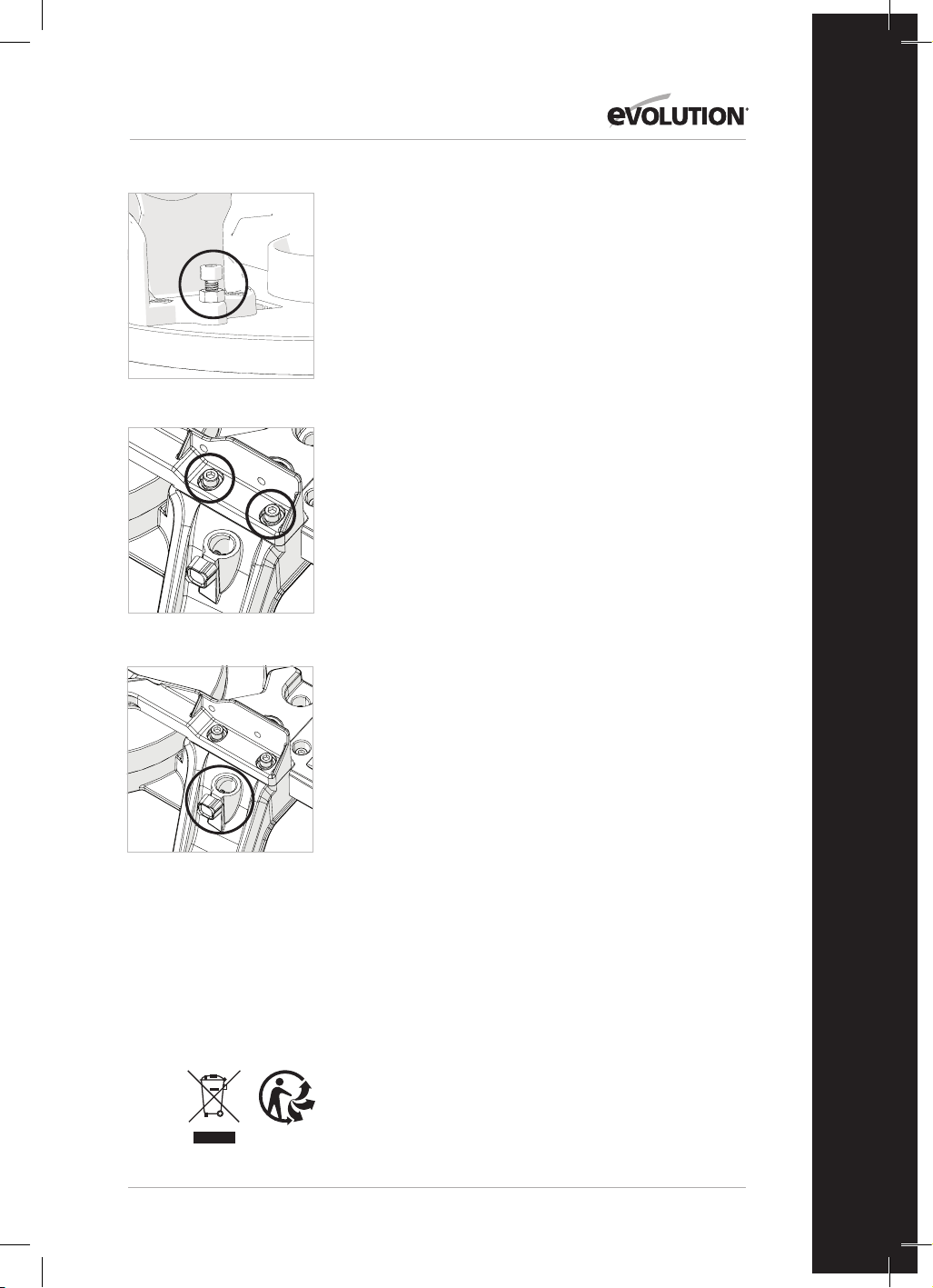
39
www.evolutionpowertools.com
DE
Falls eine Anpassung erforderlich ist:
Hinweis: Der Schneidkopf muss geneigt werden, um Zugang zur
Einstellschraube des 45°-Neigungswinkelanschlags zu erhalten.
• Lösen Sie die Feststellmutter der Einstellschraube für den
45°-Neigungswinkelanschlag leicht. (Abb.23)
• Verwenden Sie einen Sechskantschlüssel, um die
Neigungswinkel-Anschlagschraube je nach Bedarf im oder gegen
den Uhrzeigersinn zu drehen.
• Wenn die exakte Ausrichtung zwischen Blatt und Drehtisch
erreicht ist, ziehen Sie die Mutter fest.
EINSTELLUNG DES ANSCHLAGS (Abb. 24a & 24b)
Der Anschlag ist mit vier Innensechskantschrauben, zwei auf jeder
Seite, am Sockel der Maschine befestigt. Diese Schrauben befinden
sich in Langlöchern, die es ermöglichen, den Anschlag nach Bedarf
neu zu positionieren.
Der Anschlag sollte im exakten 90°-Winkel zu einem korrekt
eingesetzten Sägeblatt eingestellt sein. Für die genaue
Positionierung des Anschlags wird ein Präzisionswinkel (nicht im
Lieferumfang enthalten) benötigt.
Einstellen des Anschlags:
• Stellen Sie den Drehtisch auf einen Gehrungswinkel von 0˚ ein.
• Stellen Sie den Schneidkopf auf einen Neigungswinkel von 0˚.
• Lösen Sie die vier Innensechskantschrauben des Anschlags leicht.
• Führen Sie den Schneidkopf in seine unterste Position.
• Überprüfen Sie die Ausrichtung des Anschlags mit dem Blatt mit
Hilfe des Präzisionswinkels.
• Richten Sie den Anschlag nach Bedarf aus und ziehen Sie dann
die Innensechskantschrauben fest.
INSTANDHALTUNG UND EINSTELLUNGEN
WARNUNG: Stellen Sie sicher, dass das Gerät vom Stromnetz
getrennt ist, bevor Wartungsarbeiten oder Anpassungen
vorgenommen werden.
Reinigung
Nach jedem Gebrauch sollte die Maschine gereinigt werden.
Entfernen Sie alle Sägespäne usw. von den sichtbaren Teilen
der Maschine mit einem Staubsauger. Ein Staubsauger kann
auch an den Absauganschluss auf der Rückseite der Maschine
angeschlossen werden. Dadurch wird das Innere der Maschine von
Verunreinigungen befreit. Verwenden Sie niemals Lösungsmittel
zur Reinigung von Kunststoffteilen, da diese dadurch beschädigt
werden können. Reinigen Sie diese nur mit einem weichen, leicht
feuchten Tuch.
Um die Lebensdauer des Geräts zu verlängern, ölen Sie die
rotierenden Teile einmal im Monat. Ölen Sie nicht den Motor.
Verwenden Sie zur Reinigung des Kunststoffs keine ätzenden
Produkte.
WARNUNG: Das Werkzeug darf nicht mit Wasser in Berührung
kommen.
UMWELTSCHUTZ
Elektroschrott nicht mit dem Haushaltsmüll entsorgen. Nach
Möglichkeit recyceln. Für Informationen hinsichtlich Recycling
wenden Sie sich bitte an Ihre Behörde vor Ort oder Ihren Händler.
Abb. 23
Abb. 24a
Abb. 24b
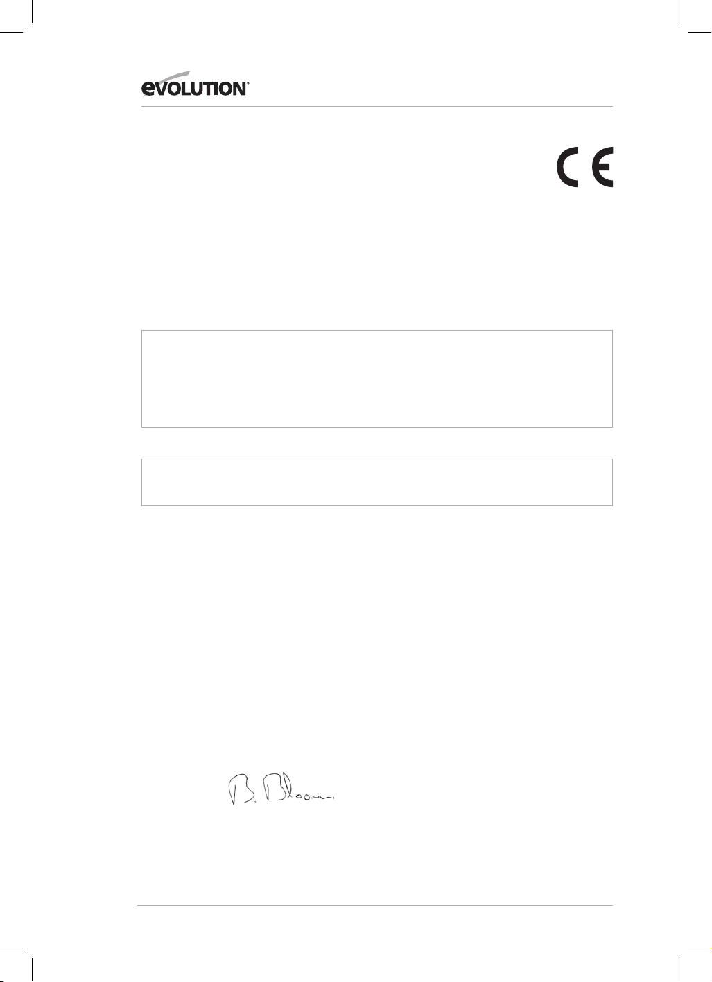
40
www.evolutionpowertools.com
EG-KONFORMITÄTSERKLÄRUNG
Der Hersteller des von dieser Konformitätserklärung gedeckten Produktes ist:
UK: Evolution Power Tools, Venture One, Longacre Close, Holbrook Industrial Estate, Sheeld, S20 3FR.
FR: Evolution Power Tools SAS. 61 Avenue Lafontaine, 33560, Carbon-Blanc, Bordeaux, Frankreich.
Hiermit erklärt der Hersteller, dass die Maschine wie in dieser Erklärung dargestellt allen relevanten Auagen der
Maschinenrichtlinie und anderer betreender weiter unten ausgeführten Richtlinien entspricht.
Hiermit erklärt der Hersteller ferner, dass die in dieser Erklärung angegebene Maschine, wo zutreend, die relevanten
Bestimmungen des grundlegenden Arbeitsschutzes erfüllt.
Die in dieser Erklärung berücksichtigten Richtlinien lauten wie folgt:
2006/42/EC. Maschinenrichtlinie.
2014/30/EU. Richtlinie zur elektromagnetischen Verträglichkeit
Richtlinie zur Beschränkung der Verwendung bestimmter gefährlicher
Stoe in Elektro- und Elektronikgeräten (RoHS)
2012/19/EU. Richtlinie über Elektro- und Elektronik-Altgeräte (so genannte WEEE-Richtlinie).
Und erfüllt die zutreenden Vorgaben der folgenden Dokumente:
EN 61029-1:2009+A11• EN 61029-2-11:2012+A11• EN 55014-1:2017+A11:2020 •
EN IEC 55014-1:2021 • EN IEC 55014-2:2021 • EN IEC 61000-3-2:2019+A1 •
EN IEC 61000-3-11:2019
EC type approval to 2006/42/EC Article 12 Section 3b Machinery
TÜV Rheinland LGA Products GmbH - Tillystraße 2 - 90431 Nürnberg
No.: 0197 Reg. No.: BM 50592380 0001
Produktdetails
Beschreibung: R210MTS G2 210mm MEHRZWECK-TISCH-/GEHRUNGSSÄGE
Evolution Modellnummer: 116-0001, 116-0002, 116-0003, 116-0004
Markenname: EVOLUTION
Spannung: 220-240V ~ 50Hz
Energiezufuhr: 1500W
Die technischen Unterlagen, die notwendig sind, um zu belegen, dass dieses Produkt den Anforderungen der Richtlinie
entspricht, wurden von der zuständigen Vollzugsbehörde eingefordert und können dort zur Inspektion eingesehen
werden. Diese Unterlagen belegen, dass unser technisches Verzeichnis die oben aufgeführten Dokumente enthält und
dass diese den korrekten Normen für dieses Produkt, wie oben aufgeführt, entsprechen.
Name und Adresse der für das technische Verzeichnis verantwortlichen Person.
Unterschrift: Druck: Barry Bloomer
Supply Chain & Procurement Director
Datum: 08.02.22
UK: Evolution Power Tools, Venture One, Longacre Close, Holbrook Industrial Estate, Sheeld, S20 3FR.
FR: Evolution Power Tools SAS. 61 Avenue Lafontaine, 33560, Carbon-Blanc, Bordeaux, Frankreich.
2011/65/EU. &
2015/863/EU.

41
www.evolutionpowertools.com
DE

42
www.evolutionpowertools.com
IMPORTANTE
Lea estas instrucciones de manejo y seguridad
detenidamente y en su totalidad.
Por su propia seguridad, si no está seguro de
algún aspecto relacionado con el uso de este
equipo, póngase en contacto con el servicio
de asistencia técnica pertinente. Encontrará
el número de teléfono en la página web de
Evolution Power Tools.
Nuestra organización dispone de varios teléfonos
de soporte en todo el mundo, aunque su
proveedor también puede ofrecerle asistencia
técnica.
WEB
www.evolutionpowertools.com
CORREO ELECTRÓNICO
REINO UNIDO:
customer[email protected]
EE. UU.:
evolutioninfo@evolutionpowertools.com
GARANTÍA
Enhorabuena por adquirir una máquina de
Evolution Power Tools. Por favor, complete el
registro de su producto en línea tal y como se
indica en el folleto adjunto a esta máquina. De
esta manera, validará el periodo de garantía
de su máquina a través de la página web de
Evolution al introducir sus datos y, así, dispondrá
de un servicio rápido si fuera necesario.
Le agradecemos sinceramente que haya
escogido un producto de Evolution Power Tools.
Evolution Power Tools se reserva el derecho a
hacer mejoras y modicaciones en el diseño del
producto sin previo aviso.
Por favor, consulte el folleto de registro de
garantía y/o el embalaje para obtener más
detalles acerca de los términos y condiciones de
la garantía.

43
www.evolutionpowertools.com
ES
ESPECIFICACIONES
MÁQUINA REINO UNIDO/UE
Motor (220-240V ~ 50 Hz) 1500W
Velocidad sin carga 3800 min
-1
Peso 13 kg
CAPACIDADES DE CORTE REINO UNIDO/UE
Placa de acero suave, grosor máximo 3 mm
Placa de acero suave, dureza máxima 210HB
MÁXIMA CAPACIDAD DE CORTE (ALUMINIO, MADERA Y PVC)
CONFIGURACIÓN DE LA SIERRA INGLETADORA
AJUSTE INGLETE REINO UNIDO/UE
0° 0° 55 x 120 mm
45° 0° 35 x 120 mm
0° 45° izquierda 55 x 65 mm
0° 45° derecha 55 x 55 mm
45° 45° izquierda 35 x 30 mm
45° 45° derecha 35 x 70 mm
MÁXIMA CAPACIDAD DE CORTE - CONFIGURACIÓN DE LA SIERRA DE MESA
CAPACIDADES DE CORTE REINO UNIDO/UE
Madera - Grosor máx. 40 mm
DIMENSIONES DE LA HOJA REINO UNIDO/UE
Diámetro 210 mm
Orificio 25.4mm
Número de dientes 20
Corte de sierra 1.7mm
DATOS DE RUIDO Y VIBRACIÓN
Presión acústica L
P
A 103 dB(A); K=3 dB(A)
Nivel de potencia acústica L
W
A 116 dB(A); K=3 dB(A)

44
www.evolutionpowertools.com
Los valores de emisión de ruido declarados
se han medido según un método de
pruebas estándar (EN 61029-1, EN 61029-
2-11) y pueden usarse para comparar una
herramienta con otra.
ADVERTENCIA: la emisión de ruido al usar la
herramienta eléctrica puede diferir del valor
total declarado dependiendo de la manera en
la que se utilice la herramienta y, sobre todo,
del tipo de pieza de trabajo que se procese.
Es necesario identificar medidas de seguridad
para proteger al operador que se basen
en una estimación de la exposición en las
condiciones reales de uso (teniendo en cuenta
todas las partes del ciclo operativo, como las
veces que se desconecta la máquina y cuando
está en reposo, además del tiempo que está
funcionando de forma seguida)
ETIQUETAS Y SÍMBOLOS
ADVERTENCIA: no utilice la máquina
si faltan etiquetas de instrucciones y/o
advertencia, o si están dañadas. Póngase en
contacto con Evolution
Power Tools para sustituir las etiquetas.
Nota: todos o algunos de los siguientes
símbolos pueden aparecer en el manual o en
el producto.
Símbolo Descripción
V
Voltios
A
Amperios
Hz
Hercios
Min
-1
Velocidad
~
Corriente alterna
n
o
Velocidad sin carga
Utilice gafas protectoras
Utilice protección auditiva
No tocar
Utilice protección contra el polvo
Lea las instrucciones
Certificado CE
Certificado UKCA
Advertencia
Residuos de aparatos eléctricos
y electrónicos
Doble aislamiento
Triman: recogida
y reciclado de residuos

45
www.evolutionpowertools.com
ES
USO PREVISTO DE ESTA HERRAMIENTA
ELÉCTRICA
ADVERTENCIA: este producto es una sierra
ingletadora compuesta de uso manual y ha
sido diseñada para usarse con hojas especiales
de Evolution. Utilice solamente accesorios
diseñados para el uso de esta máquina y/o
aquellos recomendados específicamente por
Evolution Power Tools Ltd.
Si esta máquina está equipada con una hoja
adecuada, puede cortar lo siguiente:
Acero dulce
Aluminio
Madera
Plásticos
USO PROHIBIDO DE ESTA HERRAMIENTA
ELÉCTRICA
ADVERTENCIA: este producto es una sierra
ingletadora compuesta de uso manual y solo
debe usarse como tal. No debe modificarse
de ninguna manera, ni usarse para alimentar
ningún otro equipo, ni accionar accesorios no
especificados en este manual de instrucciones.
ADVERTENCIA: esta máquina no está
diseñada para ser utilizada por personas
(niños incluidos) con capacidades físicas,
sensoriales o mentales reducidas o con falta
de experiencia y conocimientos, a no ser que
hayan sido supervisadas o instruidas en el
uso seguro de la máquina por una persona
responsable de su seguridad y competente en
el uso seguro de esta.
Debe supervisarse a los niños para asegurarse
de que no tienen acceso a la máquina ni
pueden jugar con ella.
SEGURIDAD ELÉCTRICA
Esta máquina está equipada con el enchufe
moldeado y cable de alimentación correctos
para el mercado designado. Si el cable de
alimentación se daña, debe reemplazarse por
un cable o ensamblaje especial del fabricante
o su agente de servicios.
USO EN EXTERIORES
ADVERTENCIA: para su protección, va a
usar esta herramienta en exteriores, no debe
exponerla a la lluvia o utilizarla en lugares
húmedos. No coloque la herramienta sobre
superficies húmedas. Si es posible, utilice un
banco de trabajo limpio y seco.
Para garantizar una mayor protección,
utilice un dispositivo de corriente residual
(RCD) que interrumpa el suministro si la
corriente de fuga a tierra es superior a 30 mA
durante 30 minutos. Compruebe siempre el
funcionamiento del dispositivo de corriente
residual (RCD) antes de utilizar la máquina.
Si se necesita un alargador, debe ser de un
tipo adecuado para uso en exteriores y estar
etiquetado para tal fin. Se deben seguir las
instrucciones de los fabricantes al utilizar un
alargador.
INSTRUCCIONES GENERALES DE SEGURIDAD
PARA HERRAMIENTAS ELÉCTRICAS
• Siga estas instrucciones antes de trabajar
con la sierra y durante el uso.
• Guarde estas instrucciones a buen recaudo.
• Evite el contacto corporal con componentes
conectados a tierra.
• Cuando no se esté usando el equipo, se
debería almacenar en un lugar seco y
cerrado, fuera del alcance de los niños.
• Trabajará mejor y de forma más segura
si mantiene sus herramientas afiladas
y limpias. Compruebe el cable de
alimentación con regularidad y solicite su
sustitución a un especialista autorizado
cuando detecte la primera señal de daño.
• Inspeccione los alargadores periódicamente
y sustitúyalos si están dañados.
• Al trabajar en exteriores, use únicamente
alargadores aprobados para su uso en
exteriores y que cuenten con el marcado
pertinente.
• Céntrese en lo que está haciendo. Adopte
una actitud sensata para el trabajo. Nunca
use la herramienta cuando esté cansado.
• Nunca use una herramienta con un
interruptor que no se puede encender y
apagar.
• ¡Precaución! El uso de herramientas y
accesorios enchufables distintos de los
previstos puede exponerle a sufrir lesiones.
• La máquina está equipada con un
interruptor de seguridad para evitar que se
encienda accidentalmente después de un
fallo del suministro eléctrico (en el modo de
sierra de mesa).
• Nunca use la sierra para cortar madera.
• Compruebe el cable de alimentación.
Nunca use un cable de alimentación
defectuoso o dañado.
• No use el cable para quitar el enchufe de la
toma de corriente. Proteja el cable del calor,
el aceite y los bordes afilados.
• Se recomienda usar calzado antideslizante
al trabajar en exteriores.
• Mantenga el pelo largo recogido con una
redecilla.
• Evite posturas de trabajo anómalas.

46
www.evolutionpowertools.com
• Una zona de trabajo desordenada puede
causar accidentes.
• No deje que otras personas, sobre todo
niños, toquen la herramienta ni el cable de
alimentación. Manténgalos alejados de su
lugar de trabajo.
• El separador es un dispositivo de seguridad
importante. No solo guía la pieza de
trabajo, sino que evita que la ranura se
cierre detrás de la hoja para que la pieza de
trabajo no provoque un contragolpe. Preste
atención al grosor del separador; este
nunca debe ser más delgado que el cuerpo
de la hoja de la sierra ni más grueso que el
ancho de su ranura.
• La protección superior de la hoja de la sierra
debe bajarse sobre la pieza de trabajo para
cada corte.
• Asegúrese de usar un empujador al cortar
piezas de trabajo estrechas de menos de
120mm de anchura o un bloque de empuje
al cortar piezas de trabajo de menos de
30mm de anchura.
IMPORTANTE: nunca use esta sierra para realizar
cortes de inmersión.
• Póngase siempre a un lado de la hoja de la
sierra al trabajar con la ingletadora.
• Asegúrese de que los recortes no se
enganchen en la corona de la hoja de la
sierra, ya que podrían salir despedidos al
área circundante.
• Si el hueco de serrado está desgastado,
sustituya el inserto de mesa.
• Para prevenir lesiones por serrín y virutas
que salen despedidos, use la sierra
solamente con un sistema de extracción
aspirador adecuado o con un aspirador
industrial estándar.
• Desenchufe siempre el enchufe de la toma
de corriente antes de ajustar o realizar el
mantenimiento de la máquina.
• Proporcione estas normas de seguridad
a todas las personas que trabajen con la
máquina.
• No use esta sierra para cortar leña.
• ¡Precaución! Las manos y los dedos pueden
resultar lesionados con la hoja de sierra
giratoria.
• Antes de utilizar la máquina por primera
vez, compruebe que la tensión que figura
en la placa de características es la misma
que la tensión de la red eléctrica.
• Si necesita usar un alargador, asegúrese de
que la sección transversal del conductor es
lo suficientemente grande para el consumo
de potencia de la sierra. Sección transversal
mínima: 1,0 mm².
• Si usa una bobina para cable, hay que sacar
todo el cable de la bobina.
• Nunca transporte la sierra mediante su
cable.
• No deje la sierra bajo la lluvia ni la use en
condiciones húmedas o mojadas.
• Disponga de una iluminación óptima.
• Nunca use la sierra cerca de líquidos o gases
combustibles.
• Utilice ropa de trabajo adecuada. Las
prendas sueltas y las joyas pueden quedar
atrapadas en la hoja de sierra giratoria.
• Los operarios deben tener al menos
18años de edad. Los aprendices de al
menos 16años pueden usar la máquina
únicamente bajo supervisión.
• Mantenga a los niños alejados de la
máquina cuando esté conectada al
suministro eléctrico.
IMPORTANTE:
• compruebe el cable de alimentación. Nunca
use un cable de alimentación defectuoso
o dañado.
• Mantenga su lugar de trabajo limpio sin
restos de madera ni objetos innecesarios.
• Las personas que trabajan con la máquina
no deberían estar distraídas.
• Preste atención a la dirección de rotación
del motor y la hoja de sierra.
• Después de apagar el motor, nunca
ralentice la hoja de la sierra aplicando
presión en un lateral.
• Instale únicamente hojas que estén
bien afiladas y no presenten grietas ni
deformaciones.
• La máquina solo se puede usar con
herramientas que cumplan la norma
EN 847-1
• Las hojas de sierra defectuosas se deben
sustituir de inmediato.
• Nunca utilice hojas de sierra que no
cumplan los datos especificados en este
manual.
• Asegúrese de que la flecha en la hoja de la
sierra coincida con la flecha marcada en la
máquina.
• Cerciórese de que la hoja de la sierra
no toca la mesa giratoria en ninguna
configuración. Para ello, desenchufe la
máquina de la corriente e incline la hoja de
la sierra a mano hasta la posición de 45° y la
posición de 90°. En caso necesario, reajuste
la cabeza de la sierra.
• Es imprescindible asegurarse de que todos
los dispositivos usados para cubrir la hoja
de la sierra están en buen estado operativo.
• Nunca haga cuña con la capucha de
protección plegable en la posición abierta.

47
www.evolutionpowertools.com
ES
CONSEJOS PARA LA SALUD
ADVERTENCIA: durante el uso de esta máquina,
se pueden producir partículas de polvo. A veces,
según los materiales con los que trabaje, este
polvo puede ser especialmente perjudicial. Si
sospecha que la pintura de la superficie del
material que desea cortar contiene plomo,
consulte a un profesional. No intente retirar
pintura que tenga base de plomo. Solo debe
hacerlo un profesional. Una vez que el polvo se
ha depositado en una superficie, el contacto de
la mano con la boca puede llevar a la ingestión
de plomo.
Incluso la exposición a niveles bajos de plomo
puede causar daños irreversibles en el cerebro
y el sistema nervioso. Los niños pequeños y
los nonatos son especialmente vulnerables. Se
recomienda que considere el riesgo asociado a
los materiales con los que trabaja y que reduzca
el riesgo de exposición. Como algunos materiales
pueden producir polvo potencialmente
dañino para su salud, recomendamos el
uso de mascarillas con filtros reemplazables
homologadas cuando use esta máquina.
Siempre debe:
• Trabajar en una zona bien ventilada.
• Trabajar con un equipo de seguridad
homologado, como mascarillas para el
polvo diseñadas específicamente para filtrar
partículas microscópicas.
ADVERTENCIA: el manejo de cualquier
herramienta eléctrica puede provocar que se
lancen objetos externos contra los ojos que
podrían ocasionar daños graves en estos. Antes
de empezar a utilizar una herramienta eléctrica,
póngase siempre gafas de seguridad completas
o con protección lateral, o una pantalla que cubra
toda la cara cuando sea necesario.
INSTRUCCIONES DE SEGURIDAD
ADICIONALES -
INGLETADORAS
Las siguientes instrucciones específicas de
seguridad para sierras ingletadoras se basan en
los requisitos de EN 61029-2-11
SEGURIDAD DE LA HOJA
ADVERTENCIA: las sierras circulares giratorias
son extremadamente peligrosas y pueden
provocar lesiones graves y amputaciones.
Mantenga los dedos y las manos alejados por
lo menos 150mm de la hoja en todo momento.
Nunca intente recuperar material serrado hasta
que la cabeza de corte esté en posición elevada,
la protección se haya cerrado completamente y la
hoja de la sierra haya dejado de girar.
Use solamente hojas de sierra recomendadas por
el fabricante, como se detalla en este manual y
que cumplan los requisitos de la norma
EN 847-1.
No use hojas de sierra dañadas o deformadas, ya
que podrían hacerse añicos y provocar lesiones
graves al operario o a las personas presentes.
No use hojas de sierra fabricadas a partir de acero
rápido (HSS).
Si el inserto de mesa se daña o desgasta, se debe
reemplazar por uno idéntico facilitado por el
fabricante como se detalla en este manual.
EQUIPO DE PROTECCIÓN
INDIVIDUAL (EPI)
Se debe llevar protección auditiva para
reducir el riesgo de pérdida de audición inducida.
Se debe llevar protección ocular a fin de prevenir
la posibilidad de perder la vista debido a astillas
desprendidas.
También se recomienda llevar protección
respiratoria, ya que algunas maderas y productos
madereros, en particular el MDF (tablero de fibras
de densidad media), pueden producir polvo que
puede ser perjudicial para la salud.
Recomendamos el uso de una mascarilla con
filtros reemplazables homologada al utilizar esta
máquina, además del de la unidad de extracción
de polvo.
Se deben llevar guantes cuando se manejen hojas
o material áspero. Se recomienda que las hojas
de sierra se lleven en un soporte siempre que sea
factible. No se recomienda llevar guantes cuando
se maneja la sierra ingletadora.
FUNCIONAMIENTO SEGURO
Compruebe siempre que ha seleccionado la hoja
de sierra correcta para el material que va a cortar.
No use esta sierra ingletadora para cortar
materiales distintos de los especificados en este
manual de instrucciones.
Al transportar una sierra ingletadora, asegúrese
de que la cabeza de corte esté bloqueada en la
posición inferior de 90 grados (en caso de una
ingletadora deslizante, asegúrese de que las
barras correderas estén bloqueadas). Levante
la máquina agarrando los bordes exteriores de
la base con ambas manos (si es una ingletadora
deslizante, transpórtela usando las asas
proporcionadas). Bajo ningún concepto se puede
levantar o transportar la máquina usando la
protección retráctil ni ninguna otra parte de su
mecanismo de funcionamiento.

48
www.evolutionpowertools.com
Antes de cada uso, compruebe el funcionamiento
de la protección retráctil y su mecanismo de
funcionamiento. Asegúrese de que no haya daños
y de que todas las piezas móviles funcionen de
forma fluida y correcta.
Mantenga el banco de trabajo y la zona del
suelo libres de restos, incluyendo serrín, virutas
y recortes.
Compruebe y asegúrese siempre de que la
velocidad indicada en la hoja de la sierra sea por
lo menos igual a la velocidad sin carga indicada
en la sierra ingletadora.
Bajo ninguna circunstancia se puede usar
una hoja de sierra que esté marcada con una
velocidad inferior a la velocidad sin carga marcada
en la ingletadora.
Si fuera necesario usar un espaciador o anillos
reductores, estos deben ser apropiados para el fin
previsto y siempre según lo recomendado por el
fabricante.
La hoja de la sierra solo se puede sustituir como
se detalla en este manual de instrucciones.
Nunca intente recuperar recortes ni ninguna otra
parte de la pieza de trabajo hasta que la cabeza
de corte esté en posición elevada, la protección se
haya cerrado completamente y la hoja de la sierra
haya dejado de girar.
REALIZAR CORTES DE MANERA CORRECTA Y
SEGURA
Siempre que sea factible, asegure la pieza de
trabajo a la mesa de la sierra usando la mordaza
de trabajo, si se proporciona.
Asegúrese siempre antes de cada corte de que la
sierra ingletadora esté montada en una posición
estable.
Si fuera necesario, se puede montar la sierra
ingletadora en una base de madera o banco de
trabajo o unirse a un soporte de sierra ingletadora
como se detalla en este manual de instrucciones.
Las piezas de trabajo largas se deben apoyar
en los soportes de trabajo proporcionados o en
soportes de trabajo adicionales apropiados.
ADVERTENCIA: si faltan piezas, no utilice la
máquina hasta que estas se reemplacen. No
seguir esta indicación puede causar graves
lesiones personales.
CONSEJOS DE SEGURIDAD ADICIONALES
TRANSPORTAR LA SIERRA INGLETADORA DE
MESA
Consejos de seguridad
• A pesar de ser compacta, esta sierra
ingletadora es pesada. Para reducir el riesgo
de lesiones en la espalda, solicite ayuda
cualificada cada vez que tenga que
levantar la sierra.
• Para reducir el riesgo de lesiones en la
espalda, sujete la herramienta cerca del
cuerpo cuando la levante. Doble las rodillas
para poder levantarla con las piernas, no con
la espalda. Levántela usando las zonas de asa a
cada lado de la base de la máquina.
• No transporte nunca la sierra ingletadora
de mesa agarrándola por el cable de
alimentación. Si se transporta la herramienta
por el cable de alimentación, se podrían causar
daños al aislamiento o las conexiones de los
cables y provocar una descarga eléctrica o un
incendio.
• Antes de mover la sierra, apriete los
tornillos de bloqueo del bisel y el inglete
para evitar movimientos bruscos e
inesperados.
• Bloquee la cabeza de corte en su posición
más baja. Asegúrese de que el seguro de la
cabeza de corte esté completamente insertado
en su cavidad.
ADVERTENCIA: no use la protección de la
hoja como «punto de elevación». El cable de
alimentación se debe desenchufar del suministro
eléctrico antes de intentar mover la máquina.
• Bloquee la cabeza de corte en la posición
inferior usando su seguro.
• Afloje el tornillo de bloqueo del ángulo de
inglete. Gire la mesa a cualquiera de sus ajustes
máximos.
• Bloquee la mesa en posición usando el
tornillo de bloqueo.
• Use las dos asas de transporte recortadas
a los lados de la base de la máquina para
transportarla.
Coloque la sierra en una superficie de trabajo
estacionaria segura y compruebe la sierra
minuciosamente.
Compruebe en particular el funcionamiento
de todas las características de seguridad de la
máquina antes de proceder al uso de la misma.
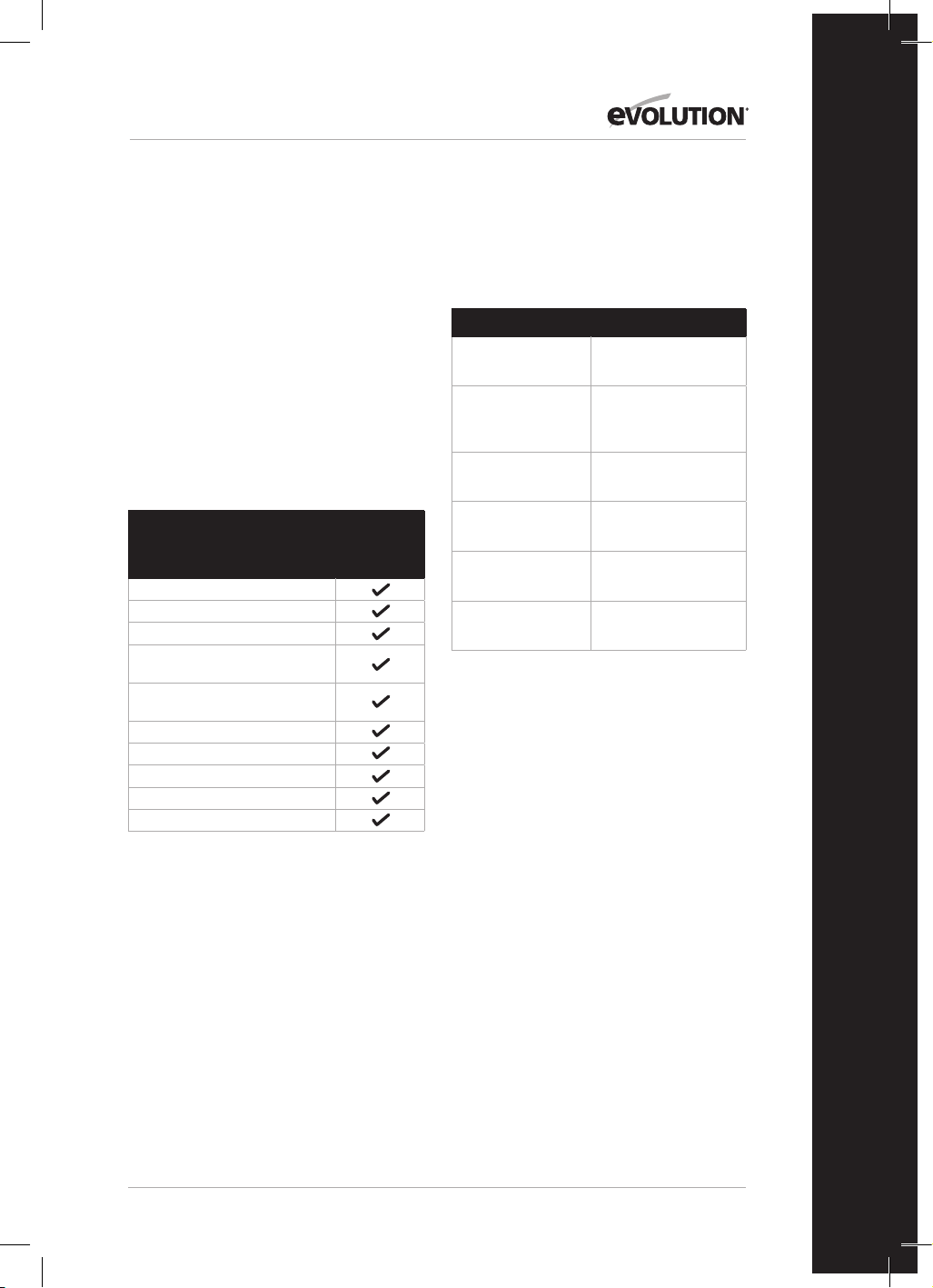
49
www.evolutionpowertools.com
ES
PRIMEROS PASOS: DESEMBALAJE
Precaución: esta caja contiene objetos afilados.
Ábrala con cuidado. Retire la máquina del
embalaje junto con los accesorios incluidos.
Compruebe que la máquina está en buenas
condiciones y que se incluyen todos los
accesorios especificados en este manual.
Asegúrese también de que todos los accesorios
están completos. Si falta alguna pieza, la máquina
o accesorios, devuélvalo todo a su distribuidor
en su embalaje original. No tire el embalaje y
consérvelo durante todo el período de garantía.
Deseche el embalaje respetando la normativa de
medioambiente. Si es posible, recíclelo. No deje
que los niños jueguen con las bolsas de plástico
vacías, ya que existe riesgo de asfixia.
ELEMENTOS SUMINISTRADOS
Descripción
116-0001,
116-0002,
116-0003,
116-0004
Manual de instrucciones
Mordaza de sujeción
Empujador
Llave de espigas
(cambio de hoja)
Llave Allen de doble extremo
6-5mm
Hojas multiusos
Tope guía
Saco captapolvo
Protección de la sierra de mesa
Extensiones laterales de la base x2
ACCESORIOS ADICIONALES
Además de los elementos estándar suministrados
con esta máquina, también ponemos a su
disposición los siguientes accesorios que
encontrará en la tienda en línea de Evolution en
www.evolutionpowertools.com o en su
distribuidor local.
Descripción N.º de pieza
Hoja TCT multimaterial
RAGE
RAGEBLADE210MULTI
Hoja general de
210mm
para madera
GW210TCT-30
Hoja de 210mm
para madera fina
FW210TCT-40
Hoja de 210mm
de diamante
D210CON
Soporte para
ingletadora
005-0001
Soporte para
ingletadora +
005-0005

50
www.evolutionpowertools.com
DESCRIPCIÓN GENERAL DE LA MÁQUINA R210MTS-G2
1
3
8
1. MANGO DE CORTE
2. MESA GIRATORIA
3. PROTECCIÓN INFERIOR RETRÁCTIL DE LA
HOJA
4. MANGO DE BLOQUEO DEL ÁNGULO DE
INGLETE
5. ESCALA DE ÁNGULOS DE INGLETE
6. PALANCA DE LIBERACIÓN DE LA CABEZA
DE CORTE
7. PIN DE BLOQUEO DE LA CABEZA DE
CORTE
8. ALMACENAMIENTO DEL EMPUJADOR
9. INTERRUPTOR DE ENCENDIDO/APAGADO
DE LA SIERRA DE MESA
10. GATILLO DE ENCENDIDO/APAGADO DE
LA INGLETADORA
2
9
10
4
6
5
7

51
www.evolutionpowertools.com
ES
DESCRIPCIÓN GENERAL DE LA MÁQUINA R210MTS-G2
1. PARTE SUPERIOR DE LA MESA
2. PROTECCIÓN DE LA SIERRA DE MESA
3. TOPE GUÍA
4. EMPUJADOR
5. SEGURO DEL MODO DE MESA/INGLETE
6. PALANCA DE BLOQUEO DEL BISEL
7. BRAZO ESTABILIZADOR TRASERO
8. SOPORTES DE LA PIEZA DE TRABAJO (X2)
9. ALMACENAMIENTO DE HERRAMIENTAS
10. PALANCAS DE BLOQUEO DEL TOPE GUÍA (X2)
11. ESCALAS DE LA SUPERFICIE DE LA MESA
2
4
3
1
7
8
9
5
6
10
10
11
11

52
www.evolutionpowertools.com
PRIMEROS PASOS
ADVERTENCIA: DESCONECTE SIEMPRE LA SIERRA DE LA FUENTE
DE ALIMENTACIÓN ANTES DE HACER AJUSTES.
MONTAJE PERMANENTE DE LA R210MTS-G2 -
SIERRA DE MESA/INGLETADORA (Fig. 1)
ADVERTENCIA: para reducir el riesgo de lesiones debidas al
movimiento inesperado de la sierra, colóquela en la ubicación
deseada, o bien en un banco de trabajo o en otro juego de
patas recomendado. La base de la sierra tiene cuatro orificios
para montar la sierra ingletadora. Si se va a usar la sierra en
una ubicación, fíjela de forma permanente al banco de trabajo
o juego de patas usando los pernos apropiados con tuercas y
arandelas de bloqueo.
1. Apriete los bloqueos del bisel y del inglete.
2. Coloque la sierra de forma que otras personas no puedan estar
detrás. Los residuos que salen disparados podrían lesionar a las
personas en su trayectoria.
3. Coloque la sierra sobre una superficie firme y nivelada en la
que haya suficiente espacio para manejar y apoyar la pieza de
trabajo de forma adecuada.
4. Apoye la sierra para que la mesa esté nivelada y la sierra no se
balancee.
5. Fije la sierra con mordazas o pernos a su soporte.
BARRA ESTABILIZADORA TRASERA
Extienda la barra hasta la parte trasera de la máquina (Fig. 2)
PROTECCIÓN DE LA SIERRA DE MESA
Para instalar la protección de la sierra de mesa:
• Con la llave hexagonal, afloje los 2 tornillos hexagonales
• Instale el conjunto de la protección de la sierra de mesa (Fig.3)
• Apriete los 2tornillos hexagonales
INSTALACIÓN/RETIRADA DE LA HOJA
ADVERTENCIA: utilice solo hojas Evolution originales que
hayan sido diseñadas para su uso en esta máquina. Asegúrese
de que la velocidad máxima de la hoja es compatible con la
máquina. Realice esta operación tan solo cuando la máquina esté
desconectada del suministro eléctrico.
Nota: se recomienda que el operario lleve guantes protectores
cuando manipule la hoja durante la instalación o cuando cambie
la hoja de la máquina.
Para cambiar una hoja:
• Saque el seguro (Fig. 4) para liberar el motor.
• Presione ligeramente hacia abajo el mango de la cabeza de
corte.
• Saque el gancho de cerrojo de la cabeza de corte y permita
que esta suba hasta su posición más elevada. (Fig. 5)
• Use la llave de espigas (suministrada) para sujetar la brida
exterior de la hoja.
• Use la llave Allen (suministrada) para desatornillar el tornillo del
eje. (Fig. 6)
Fig. 1
1) Perno de cabeza
hexagonal
2) Arandela elástica
3) Arandela plana
4) Base de la sierra
ingletadora
5) Banco de trabajo
6) Arandela plana
7) Arandela elástica
8) Tuerca hexagonal
9) Contratuerca
(1)
(2)
(3)
(4)
(5)
(6)
(7)
(8)
(9)
Fig. 2
Fig. 4
Fig. 3

53
www.evolutionpowertools.com
ES
Nota: el tornillo del eje tiene una rosca a la izquierda. Gire en
sentido horario para aflojar y antihorario para apretar.
• Retire el tornillo del eje y la brida exterior de la hoja.
• Retraiga la protección inferior de la hoja presionando la
palanca de liberación de la cabeza de corte y gire la protección
inferior hacia arriba exponiendo la hoja.
• Quite la hoja retirándola hacia afuera para despejar el extremo
del eje y, después, hacia abajo y hacia delante para sacarla de
la máquina. (Fig. 7)
Doladera
La doladera es un componente muy importante y viene instalada
en la protección superior de la hoja. La doladera evita que
el trabajo se atasque cuando atraviesa la hoja. Inspeccione
la doladera a intervalos regulares y sustitúyala si estuviera
desgastada o dañada.
La doladera se debe ajustar de modo que su borde y el
hueco entre las puntas de los dientes de la hoja sea de
aproximadamente 3-5mm. (Fig. 8)
Para ajustar la doladera, afloje ligeramente los dos tornillos de
fijación (Fig. 9) con una llave Allen. Cuando se haya logrado el
alineamiento correcto, apriete los tornillos de fijación.
Nota: use únicamente un conjunto de protección superior
de la hoja original de Evolution, ya que es un componente
específico para esta máquina. Las piezas no originales podrían ser
peligrosas. En caso de duda, contacte con el servicio de asistencia
técnica.
CONFIGURAR LA R210MTS-G2 PARA SU USO COMO SIERRA
INGLETADORA
ADVERTENCIA: realice este procedimiento tan solo cuando la
máquina esté desconectada de la fuente de alimentación.
Precaución: la R210MTS-G2 tiene muchas características
y bloqueos de seguridad integrados. Es importante leer,
comprender y respetar las siguientes instrucciones. Si no se
realiza el procedimiento de configuración, se podrían producir
daños en la máquina o lesiones al operario.
• Saque el seguro (Fig. 4) para liberar el motor.
• Presione ligeramente hacia abajo el mango de la cabeza de
corte.
• Saque el gancho de cerrojo de la cabeza de corte y permita
que esta suba hasta su posición más elevada. (Fig. 5)
La R210MTS-G2 está ahora lista para su uso como sierra
ingletadora.
SOPORTES DE LA PIEZA DE TRABAJO
Se deben instalar soportes de la pieza de trabajo a ambos lados
de la máquina (Fig.10)
Fig. 5
Fig. 8
Fig. 6
Fig. 7

54
www.evolutionpowertools.com
MORDAZA DE SUJECIÓN
Se suministra una mordaza de sujeción con la R210MTS-G2.
Se incorporan dos cavidades (una a cada lado) en la parte
posterior de la guía de la máquina. (Fig. 11)
• Encaje el pilar de la mordaza en la cavidad que mejor se
adapte a la aplicación de corte, asegurándose de que esté
insertada completamente.
• Apriete el tornillo de mariposa de la guía para bloquear el pilar
de la mordaza de sujeción en la cavidad de la guía.
• Coloque la pieza de trabajo sobre la mesa giratoria y contra la
guía.
• Ajuste la mordaza de sujeción para que sujete de forma segura
la pieza de trabajo a la mesa giratoria.
• Antes de intentar realizar cualquier corte, compruebe que la
mordaza no interfiere con el recorrido de la hoja cuando se
baja la cabeza de corte.
INSTRUCCIONES DE FUNCIONAMIENTO PARA LA
CONFIGURACIÓN DE LA SIERRA INGLETADORA
1. Liberación de la cabeza de corte
Nota: cuando está configurada en el modo de sierra ingletadora,
la cabeza de corte se bloqueará automáticamente en su posición
superior con la protección inferior retráctil de la hoja cubriendo
completamente los dientes de esta.
Para liberar la cabeza de corte, presione y mantenga presionada
la palanca de liberación de la cabeza de corte.
(Fig. 12)
Presione suavemente hacia abajo el mango de la cabeza de corte
para bajarla. El funcionamiento de la protección inferior retráctil
de la hoja es automático cuando está en contacto con la pieza de
trabajo.
2. Posicionamiento del cuerpo y la mano (Fig. 13)
• Nunca ponga las manos en la «zona libre de manos» (por lo
menos a 150mm de la hoja). Los pictogramas de la mesa
giratoria de la máquina se proporcionan como ayuda para
unas prácticas de trabajo seguras. Mantenga las manos
alejadas del recorrido de la hoja.
• Sujete la pieza de trabajo firmemente a la guía para evitar
cualquier movimiento. Use una mordaza de sujeción si es
posible, pero compruebe que esté posicionada de forma que
no interfiera con el recorrido de la hoja u otras piezas móviles
de la máquina.
• Antes de intentar un corte, haga una prueba con la corriente
desconectada para ver el recorrido de la hoja.
• Mantenga las manos en posición hasta que se haya liberado el
gatillo ON/OFF y la hoja se haya detenido completamente.
3. Funcionamiento del gatillo interruptor ON/OFF de la
sierra ingletadora
Accione el interruptor para encender el motor de la máquina.
Suelte el interruptor para apagar el motor de la máquina.
(Fig. 14)
Fig. 11
Fig. 12
Fig. 10
Fig. 9

55
www.evolutionpowertools.com
ES
Fig. 13
4. Corte de tronzado
La cabeza de corte se empuja suavemente hacia abajo para cortar
la pieza de trabajo.
• Coloque la pieza de trabajo sobre la mesa giratoria y contra la
guía en la posición deseada. Asegure con mordaza(s) según
sea apropiado.
• Agarre el mango de corte.
• Encienda el motor usando el gatillo interruptor y permita que
la hoja alcance toda su velocidad operativa.
• Presione y mantenga presionada la palanca de liberación de la
cabeza de corte para liberar la cabeza de corte.
• Baje suavemente la cabeza de corte a su posición más baja,
cortando la pieza de trabajo.
• Cuando haya completado el corte, apague el motor liberando
el gatillo interruptor. Permita que la hoja se detenga
completamente. • Deje que la cabeza de corte suba a su
posición superior.
• Solo puede retirar las manos o la pieza de trabajo de la
máquina cuando la cabeza de corte esté en su posición
superior con los dientes de la hoja cubiertos completamente
por la protección retráctil de la hoja.
5. Corte de inglete
Está disponible cualquier ángulo desde 46° a la izquierda hasta
46° a la derecha, y la parte delantera de la mesa giratoria incluye
una escala del transportador de ángulos.
Se proporcionan topes positivos para 0˚, 15˚, 22,5˚, 31,6˚ y 45˚ a la
izquierda y la derecha del movimiento angular.
Nota: la mesa giratoria siempre debe estar bloqueada en
posición con el mango de bloqueo del ángulo de inglete, incluso
si se ha seleccionado un tope positivo.
Para seleccionar un ángulo de inglete:
• Afloje el mango de bloqueo del ángulo de inglete. (Fig.15)
• Gire la mesa giratoria al ángulo requerido.
• Apriete de forma segura el mango de bloqueo del ángulo de
inglete cuando se haya seleccionado el ángulo deseado.
Ahora se puede realizar un corte de inglete usando las mismas
técnicas que se describen anteriormente para el corte de
tronzado.
6. Corte de bisel
La cabeza de corte se puede ajustar en cualquier ángulo hasta 47°
solo en el lado izquierdo.
La palanca de bloqueo del bisel se encuentra en la parte trasera
de la máquina.
El mecanismo de bisel incorpora una guía de transportador de
ángulos y un puntero para facilitar la configuración. (Fig.16)
Para configurar un ángulo de bisel:
• Afloje el mango de bloqueo del bisel
• Incline la cabeza de corte en el ángulo deseado. Use la guía del
transportador de ángulos para facilitar el ajuste.
• Asegúrese de que el mango de bloqueo del bisel esté apretado
de forma segura cuando se haya logrado el ángulo deseado.
Ahora se puede realizar un corte de bisel usando las mismas
No-Hands ZoneNo-Hands Zone
Fig. 14
Fig. 15
Fig. 16

56
www.evolutionpowertools.com
técnicas que se describen previamente.
Nota: realice siempre una prueba con la máquina desconectada
para que se pueda comprobar el recorrido de la hoja. Algunos
cortes compuestos y de bisel pueden requerir que la mordaza de
sujeción se sitúe en el lado derecho de la cabeza de corte. Esto
puede ser necesario para evitar la interferencia con la hoja y otras
piezas de la máquina cuando se baja la cabeza de corte.
7. Corte compuesto
Un corte compuesto es una combinación de corte de bisel y de
inglete.
• Ajuste el ángulo de inglete requerido como se describe
anteriormente.
• Ajuste el ángulo de bisel como se describe anteriormente.
• Asegúrese de que todos los tornillos de ajuste/bloqueo estén
apretados y realice una prueba para comprobar el recorrido de
la hoja.
• Realice el corte como se describe anteriormente.
8. Liberación de material atascado
• Apague la sierra ingletadora y permita que la hoja se detenga
completamente.
• A ser posible, permita que la cabeza de corte suba a su
posición superior.
• Desenchufe la sierra ingletadora de la red eléctrica.
• Retire con cuidado cualquier material atascado de la máquina.
CONFIGURAR LA R210MTS-G2 PARA SU USO COMO SIERRA
DE MESA
ADVERTENCIA: no corte metal ni materiales metálicos cuando la
máquina esté configurada como sierra de mesa.
ADVERTENCIA: realice este procedimiento tan solo cuando la
máquina esté desconectada de la fuente de alimentación.
• Asegúrese de que la mesa giratoria está configurada en un
ángulo de inglete de 0° y de que la cabeza de corte está
ajustada en un ángulo de bisel de 0°.
• Baje la cabeza de corte hasta la posición más inferior. Lleve el
gancho de cerrojo de la cabeza de corte en su cavidad.
(Fig. 17)
• Retraiga el gancho de cerrojo del motor y gire el motor hacia
arriba. (Fig. 18)
La R210MTS-G2 está ahora lista para su uso como sierra de mesa.
(Fig. 19)
CONJUNTO DE LA GUÍA COMO TOPE GUÍA
Para usar el conjunto de la guía como tope guía, la guarda se
debe alinear de forma precisa con la hoja.
ADVERTENCIA: realice este procedimiento tan solo cuando la
máquina esté desconectada de la fuente de alimentación.
Fig. 18
Fig. 17
Fig. 19

57
www.evolutionpowertools.com
ES
Para alinear el tope guía:
• Ajuste el bisel a 0˚ usando las escalas de medición de la mesa.
• Alinee el tope usando las escalas de la superficie de la mesa y
bloquéelo en posición con las 2palancas de bloqueo.
OPERACIONES BÁSICAS DE LA SIERRA DE MESA
ADVERTENCIA: no corte metal ni materiales metálicos cuando la
máquina esté configurada como sierra de mesa.
ADVERTENCIA: nunca intente realizar cortes a mano alzada en
esta máquina. Use siempre un tope guía ajustado correctamente
para minimizar la posibilidad de que la hoja se atasque y se
produzca un contragolpe.
ADVERTENCIA: esta máquina no es adecuada para el corte de
rebajes o ranuras con tope.
Nota: en caso necesario, se puede conectar un dispositivo de
extracción de polvo del taller en el canal de extracción situado en
el lado izquierdo de la máquina.
1. Interruptores ON/OFF de la sierra de mesa (Fig. 20)
• Presione el botón verde (I) para encender el motor.
• Presione el botón rojo (O) para apagar el motor.
2. Corte al hilo
Nota: compruebe que el tope guía esté bloqueado en posición
y que esté paralelo a la hoja de la sierra. Compruebe que la
doladera esté alineada correctamente con la hoja de la sierra.
Cuando se corta al hilo una pequeña sección de material, se debe
usar un empujador para alimentar/guiar los últimos 300mm
del material a través de la hoja. Siempre se debería usar un
empujador al realizar cortes de menos de 300mm.
Nota: se suministra un empujador con la R210MTS-G2 y cuenta
con una posición de almacenamiento específica en la parte
delantera de la máquina.
Recomendamos almacenar el empujador en la máquina cuando
no se esté usando. (Fig. 21)
Cuando se cortan al hilo tableros largos o paneles grandes,
use siempre un soporte de trabajo remoto o pida ayuda a una
persona formada y competente.
Las manos nunca deberían estar en la trayectoria de la hoja.
Nota: si se daña el empujador, se debe reemplazar.
COMPROBACIÓN Y AJUSTE DE LOS ÁNGULOS DE BISEL
ADVERTENCIA: antes de realizar cualquier ajuste, asegúrese
de que la máquina está desconectada del suministro
eléctrico.
Nota: aunque todos los ajustes angulares se han configurado de
fábrica, puede ser necesaria la comprobación y el ajuste como
consecuencia de un desgaste operativo normal.
Fig. 20
Fig. 21

58
www.evolutionpowertools.com
Nota: para comprobar y ajustar los ángulos de bisel, la máquina
debe estar en la configuración de sierra ingletadora.
ÁNGULO DE BISEL DE 0°
A un ángulo de bisel de 0°, la hoja debería estar perpendicular y
a exactamente 90° de la mesa giratoria. Se necesita una escuadra
de ingeniero precisa (no suministrada) para comprobar el ángulo
de bisel de 0°.
Para comprobar:
• Asegúrese de que la cabeza de corte está en posición vertical,
contra su tope y con el puntero de bisel indicando el ángulo de
bisel de 0°.
• Apriete el mango de bloqueo del bisel.
• Baje la cabeza de corte a su posición más baja. Bloquéela en
posición usando el seguro de la cabeza y suba manualmente la
protección inferior de la hoja.
• Ahora se puede usar la escuadra de ingeniero para comprobar
el ángulo entre la hoja y la mesa giratoria.
Si se requiere el ajuste:
Nota: la cabeza de corte tendrá que estar inclinada para poder
acceder al tornillo de ajuste del tope del bisel de 0°.
• Afloje ligeramente la contratuerca del tornillo de ajuste del
tope del bisel de 0°. (Fig. 22)
• Use una llave Allen para girar el tornillo de tope del bisel hacia
la derecha o la izquierda, según se requiera.
• Cuando se logre un alineamiento exacto entre la
hoja y la mesa giratoria, apriete la contratuerca.
ÁNGULO DE BISEL DE 45°
El ángulo de bisel de 45° se puede comprobar de forma similar al
ángulo de bisel de 0°. Se necesitará una escuadra de ingeniero de
45° precisa (no suministrada).
Para comprobar:
• Asegúrese de que la cabeza de corte está inclinada hacia
la posición de 45°, contra su tope y con el puntero de bisel
indicando el ángulo de bisel de 45˚.
• Apriete el mango de bloqueo del bisel.
• Baje la cabeza de corte a su posición más baja. Bloquéela en
posición usando el seguro de la cabeza y suba manualmente la
protección inferior de la hoja.
• Use la escuadra de ingeniero de 45° para comprobar el ángulo
entre la hoja y la mesa giratoria.
Fig. 22

59
www.evolutionpowertools.com
ES
Si se requiere el ajuste:
Nota: la cabeza de corte tendrá que estar inclinada para poder
acceder al tornillo de ajuste del tope del bisel de 45°.
• Afloje ligeramente la contratuerca del tornillo de ajuste del
tope del bisel de 45°. (Fig. 23)
• Use una llave Allen para girar el tornillo de tope del bisel hacia
la derecha o la izquierda, según se requiera.
• Cuando se logre un alineamiento exacto entre la hoja y la
mesa giratoria, apriete la contratuerca.
AJUSTE DE LA GUÍA (Fig. 24a y 24b)
La guía está sujeta a la base de la máquina mediante cuatro
tornillos de cabeza hueca hexagonal, dos a cada lado. Estos
tornillos están situados en orificios alargados que permiten
recolocar la valla según se requiera.
La guía debe estar ajustada a exactamente 90° de una hoja
instalada correctamente. Se necesitará una escuadra de ingeniero
precisa (no suministrada) para posicionar la valla con exactitud.
Para recolocar la guía:
• Ajuste la mesa giratoria a un ángulo de inglete de 0°.
• Ajuste la cabeza de corte a un ángulo de bisel de 0°.
• Afloje ligeramente los cuatro tornillos de cabeza hueca
hexagonal de la guía.
• Baje la cabeza de corte a su posición más baja.
• Compruebe el alineamiento de la guía con la hoja usando la
escuadra de ingeniero.
• Alinee la guía según sea necesario y apriete los tornillos de
cabeza hueca hexagonal.
MANTENIMIENTO Y AJUSTES
ADVERTENCIA: asegúrese de que la máquina está desconectada
del suministro eléctrico antes de realizar cualquier tarea de
mantenimiento o ajuste.
Limpieza
La máquina se debería limpiar después de cada uso. Retire
todo el serrín, etc. de las partes visibles de la máquina con un
aspirador. También se puede conectar un aspirador en el puerto
de extracción de polvo de la parte trasera de la máquina. De este
modo, se retirarían los residuos del interior de la máquina. Nunca
use disolventes para limpiar las partes de plástico, ya que podrían
dañarlas. Limpie solamente con un paño suave ligeramente
humedecido.
Para prolongar la vida útil de la herramienta, engrase las piezas
giratorias una vez al mes. No engrase el motor. No use productos
corrosivos para limpiar el plástico.
ADVERTENCIA: el agua nunca debe entrar en contacto con la
herramienta.
PROTECCIÓN MEDIOAMBIENTAL
Los productos eléctricos no se deben tirar a la basura doméstica.
Recicle en los puntos destinados a ello. Consulte a la autoridad
local o el vendedor para obtener más información sobre el
reciclaje.
Fig. 23
Fig. 24a
Fig. 24b

60
www.evolutionpowertools.com
DECLARACIÓN DE CONFORMIDAD CE
El fabricante del producto incluido en esta Declaración es el siguiente:
Reino Unido: Evolution Power Tools Ltd., Venture One, Longacre Close, Holbrook Industrial Estate,
Sheeld, S20 3FR (Reino Unido).
FR: Evolution Power Tools SAS. 61 Avenue Lafontaine, 33560, Carbon-Blanc, Burdeos (Francia).
El fabricante declara que la máquina, tal y como se detalla en la presente Declaración, cumple todas las disposiciones
pertinentes de la Directiva relativa a las máquinas y otras directivas apropiadas, tal y como se especica a continuación.
Asimismo, el fabricante declara que la máquina, tal y como se indica detalladamente en la presente Declaración, en los
casos en los que sea aplicable, cumple con las disposiciones pertinentes sobre los requisitos esenciales de seguridad y
salud.
Las Directivas incluidas en esta Declaración se detallan a continuación:
2006/42/CE. Directiva relativa a las máquinas.
2014/30/UE. Directiva de compatibilidad electromagnética.
Directiva sobre restricciones a la utilización de determinadas sustancias peligrosas
en aparatos eléctricos y electrónicos.
2012/19/UE. Directiva sobre residuos de aparatos eléctricos y electrónicos (RAEE).
Y está en conformidad con los requisitos aplicables de los siguientes documentos:
EN 61029-1:2009+A11• EN 61029-2-11:2012+A11• EN 55014-1:2017+A11:2020 •
EN IEC 55014-1:2021 • EN IEC 55014-2:2021 • EN IEC 61000-3-2:2019+A1 •
EN IEC 61000-3-11:2019
EC type approval to 2006/42/EC Article 12 Section 3b Machinery
TÜV Rheinland LGA Products GmbH - Tillystraße 2 - 90431 Nürnberg
No.: 0197 Reg. No.: BM 50592380 0001
Detalles del producto
Descripción: SIERRA INGLETADORA/DE MESA MULTIMATERIAL DE 210mm R210MTS G2
N.º de modelo
Evolution: 116-0001, 116-0002, 116-0003, 116-0004
Marca comercial: EVOLUTION
Voltaje: 220-240V~ 50Hz
Entrada: 1500 W
La documentación técnica necesaria para demostrar que el producto cumple con los requisitos de la directiva se ha
elaborado y está disponible para su inspección por parte de las autoridades competentes pertinentes. Garantiza que
nuestro archivo técnico contiene los documentos enumerados anteriormente y que estas son las normas correctas para el
producto, tal y como se ha detallado antes.
Nombre y dirección del titular de la documentación técnica.
Firmado: Impresión: Barry Bloomer
Director de adquisiciones y cadena de suministro
Fecha: 08/02/2022
Reino Unido: Evolution Power Tools Ltd., Venture One, Longacre Close, Holbrook Industrial Estate,
Sheeld, S20 3FR (Reino Unido).
FR: Evolution Power Tools SAS. 61 Avenue Lafontaine, 33560, Carbon-Blanc, Burdeos (Francia).
2011/65/UE. y
2015/863/UE.

61
www.evolutionpowertools.com
ES

62
www.evolutionpowertools.com
IMPORTANT
Veuillez lire attentivement ces consignes
d'utilisation et de sécurité dans leur intégralité.
Pour votre propre sécurité, si vous avez des
doutes concernant un aspect de l'utilisation
de cet appareil, veuillez contacter l'assistance
technique appropriée dont le numéro se trouve
sur le site Internet d'Evolution Power Tools.
Nous assurons différentes lignes d'assistance
téléphoniques au sein de notre société à l'échelle
mondiale, mais une assistance technique
est également disponible auprès de votre
fournisseur.
SITE INTERNET
www.evolutionpowertools.com
E-MAIL
RU:
customer[email protected]
États-Unis:
evolutioninfo@evolutionpowertools.com
GARANTIE
Félicitations pour votre achat d’un appareil
Evolution Power Tools. Veuillez enregistrer votre
produit «en ligne» comme expliqué dans le
dépliant fourni avec cet appareil. Cela vous
permettra de valider la période de garantie
de l'appareil via le site Internet d’Evolution en
saisissant vos coordonnées, ce qui vous garantit
un service rapide si nécessaire.
Nous vous remercions sincèrement d’avoir choisi
un produit de la gamme Evolution Power Tools.
Evolution Power Tools se réserve le droit de
modier et d'améliorer le produit, sans avis
préalable.
Veuillez vous reporter à la notice
d'enregistrement de la garantie et/ou à
l'emballage pour prendre connaissance des
détails des modalités de la garantie.

63
www.evolutionpowertools.com
FR
CARACTÉRISTIQUES
APPAREIL RU/UE
Moteur (220-240V ~ 50 Hz) 1500W
Vitesse à vide 3800 min
-1
Poids 13kg
CAPACITÉS DE COUPE RU/UE
Plaque en acier doux - Épaisseur max. 3mm
Plaque en acier doux - Dureté max. 210HB
CAPACITÉ DE COUPE MAXIMALE (ALUMINIUM, BOIS ET PVC)
CONFIGURATION DE LA SCIE À ONGLET
BISEAU ONGLET RU/UE
0° 0° 55 x 120mm
45° 0° 35 x 120mm
0° 45° à gauche 55 x 65mm
0° 45° à droite 55 x 55mm
45° 45° à gauche 35 x 30mm
45° 45° à droite 35 x 70mm
CAPACITÉ DE COUPE MAXIMALE - CONFIGURATION DE LA SCIE SUR TABLE
CAPACITÉS DE COUPE RU/UE
Bois - Épaisseur maximale 40mm
DIMENSIONS DE LA LAME RU/UE
Diamètre 210mm
Alésage 25.4mm
Nombre de dents 20
Trait de coupe 1.7mm
NIVEAUX SONORES ET VIBRATOIRES
Pression acoustiqueL
P
A 103 dB(A); K=3 dB(A)
Niveau de puissance acoustiqueL
W
A 116 dB(A); K=3 dB(A)
64
www.evolutionpowertools.com
Les valeurs totales des émissions sonores
déclarées ont été mesurées conformément à une
méthode d’essai standard (EN 61029-1, EN 61029-
2-11) et peuvent être utilisées pour comparer
plusieurs outils.
AVERTISSEMENT: Les émissions sonores durant
l'utilisation effective de l'outil électrique peuvent
être différentes des valeurs totales déclarées en
fonction de la manière dont l'outil est utilisé et
surtout du type de pièce à usiner.
Il est nécessaire d’identifier les mesures de
sécurité à adopter pour protéger l’opérateur
en fonction d’une estimation de l’exposition
dans les conditions effectives d’utilisation (en
tenant compte de toutes les étapes du cycle
d’opération, par exemple lorsque l’outil est mis
à l’arrêt et lorsqu’il tourne au ralenti, en plus du
déclenchement)
ÉTIQUETTES ET SYMBOLES
AVERTISSEMENT: N’utilisez pas cet appareil
si les étiquettes d’avertissement et/ou de
consignes sont manquantes ou endommagées.
Contactez Evolution
Power Tools pour le remplacement des étiquettes.
Remarque: Tous les symboles suivants ou
certains d'entre eux peuvent apparaître dans le
manuel ou sur le produit.
Symbole Description
V
Volts
A
Ampères
Hz
Hertz
Min
-1
Vitesse
~
Courant alternatif
n
o
Vitesse à vide
Portez des lunettes de sécurité
Portez des protections auditives
Ne pas toucher
Portez un dispositif de protection
contre la poussière
Lisez le mode d'emploi
Certification CE
Certification UKCA
Avertissement
Déchets électriques et
équipement électronique
Double isolation
Triman - Collecte et recyclage
des déchets

65
www.evolutionpowertools.com
FR
USAGE PRÉVU DE CET OUTIL ÉLECTRIQUE
AVERTISSEMENT: Ce produit est une
scie à onglet mixte à commande manuelle
conçue pour fonctionner avec des lames
Evolution spécifiques. Utilisez uniquement
des accessoires conçus pour l'utilisation
avec cet appareil et/ou ceux spécifiquement
recommandés par Evolution Power Tools Ltd.
Cet appareil, lorsqu'il est équipé d'une lame
appropriée, peut être utilisé pour découper les
matériaux suivants:
Acier doux
Aluminium
Bois
Plastiques
USAGE PROSCRIT DE CET OUTIL
ÉLECTRIQUE
AVERTISSEMENT: Ce produit est une scie à
onglet mixte à commande manuelle et doit
être utilisé uniquement en tant que tel. Il ne
doit en aucun cas être modifié ou utilisé pour
alimenter tout autre appareil ou entraîner tout
accessoire autre que ceux mentionnés dans le
présent mode d'emploi.
AVERTISSEMENT: Cet appareil n'est pas
conçu pour être utilisé par des personnes
(y compris les enfants) dont les capacités
physiques, sensorielles ou mentales
sont réduites, ou dénuées d'expérience
ou de connaissances, sauf si elles ont
pu bénéficier, par l'intermédiaire d’une
personne responsable de leur sécurité et
capable d'utiliser l'appareil en sécurité, d’une
surveillance ou d'instructions préalables
concernant l’utilisation de l'appareil.
Les enfants doivent être surveillés pour
garantir qu'ils n'aient pas accès à cet appareil
et qu'ils ne soient pas autorisés à jouer avec.
SÉCURITÉ ÉLECTRIQUE
Cet appareil est équipé de la fiche moulée
et du câble électrique adéquats pour le
marché désigné. Si le câble d’alimentation est
endommagé, il doit être remplacé par un câble
spécifique disponible auprès du fabricant ou
de son agent d'entretien.
UTILISATION EN EXTÉRIEUR
AVERTISSEMENT: Si vous utilisez cet outil
en extérieur, ne l’exposez pas à la pluie et ne
l’utilisez pas dans des lieux humides pour
assurer votre protection.
Ne placez pas l’outil sur des surfaces humides.
Si possible, utilisez un établi sec et propre.
Pour une protection supplémentaire, utilisez
un dispositif de courant différentiel résiduel
(DCR) qui interrompra l'alimentation si le
courant de fuite vers la terre excède 30
mA pour 30 ms. Vérifiez toujours le bon
fonctionnement du dispositif différentiel
résiduel (DCR) avant d’utiliser l'appareil.
Si vous devez utiliser une rallonge, celle-ci
doit convenir à l’utilisation en extérieur et
cette mention doit figurer sur l’étiquette.
Les instructions du fabricant doivent être
respectées lors de l’utilisation d’une rallonge.
CONSIGNES GÉNÉRALES DE SÉCURITÉ POUR
LES OUTILS ÉLECTRIQUES
• Suivez toutes ces instructions avant et
pendant que vous travaillez avec la scie.
• Conservez ce mode d’emploi dans un
endroit sûr.
• Évitez tout contact du corps avec les
composants mis à la terre.
• Lorsque l'équipement n'est pas utilisé, il
doit être conservé dans un endroit sec et
fermé, hors de portée des enfants.
• Vous travaillerez mieux et en toute
sécurité si vous gardez vos outils affûtés
et propres. Vérifiez régulièrement le câble
d'alimentation et faites-le remplacer par
un spécialiste agréé au premier signe
d'endommagement.
• Vérifiez régulièrement vos rallonges et
remplacez-les si elles sont endommagées.
• Lorsque vous travaillez à l'extérieur,
utilisez uniquement des câbles de rallonge
homologués pour l'extérieur et signalés en
conséquence.
• Concentrez-vous sur ce que vous faites.
Adoptez une attitude raisonnable vis-à-vis
de votre travail. N'utilisez jamais l'outil
lorsque vous êtes fatigué(e).
• N'utilisez jamais un outil dont l'interrupteur
ne peut être mis en marche ou arrêté.
• Mise en garde! L'utilisation d'outils et
d'accessoires à connecter autres que ceux
prévus peut vous faire courir un risque de
blessure.
• L'appareil est équipé d'un interrupteur de
sécurité pour éviter qu'il ne se remette en
marche accidentellement après une panne
de courant (en mode scie sur table).
• N'utilisez jamais la scie pour couper du
bois rond.
• Vérifiez le câble d'alimentation. N'utilisez
jamais un câble d'alimentation défectueux
ou endommagé.
• N'utilisez pas le câble pour retirer la fiche de
la prise de courant. Protégez le câble de la
chaleur, de l'huile et des bords tranchants.
• Nous vous recommandons de porter des

66
www.evolutionpowertools.com
chaussures antidérapantes lorsque vous
travaillez à l'extérieur.
• Maintenez les cheveux longs dans un filet
à cheveux.
• Évitez les postures de travail anormales.
• Une zone de travail désordonnée risque de
provoquer des accidents.
• Ne laissez pas d'autres personnes, en
particulier les enfants, toucher l'outil ou le
câble d'alimentation. Tenez-les éloignés de
votre lieu de travail.
• Le diviseur est un dispositif de sécurité
important. Non seulement il guide la pièce
à usiner, mais il empêche également le trait
de scie de se refermer derrière la lame, afin
d'éviter tout rebond de la pièce. Observez
l'épaisseur du diviseur. Le séparateur ne
doit jamais être plus fin que le corps de la
lame ni plus épais que la largeur de son
trait de scie.
• Le protège-lame supérieur doit être abaissé
au-dessus de la pièce à usiner pour chaque
coupe.
• Veillez à utiliser un poussoir pour la
découpe de pièces à usiner étroites d'une
largeur inférieure à 120mm ou un bloc
poussoir pour la coupe de pièces à usiner
étroites d'une largeur inférieure à 30mm.
IMPORTANT: N'utilisez jamais cette scie pour
effectuer des coupes plongeantes.
• Tenez-vous toujours à côté de la lame de
la scie lorsque vous travaillez avec la scie
à onglet.
• Veillez à ce que les chutes ne s'accrochent
pas à la couronne de la lame, car elles
pourraient être catapultées dans la zone
environnante.
• Si l'espace de sciage est usé, remplacez
l'insert de table.
• Pour éviter toute blessure due à la
projection de sciure et de copeaux, utilisez
la scie uniquement avec un système
d'aspiration approprié ou un aspirateur
industriel standard.
• Débranchez toujours la fiche de la prise
de courant avant de régler ou d'entretenir
l'appareil.
• Remettez ces consignes de sécurité à toutes
les personnes qui travaillent sur l'appareil.
• N'utilisez pas cette scie pour couper du bois
de chauffage.
• Mise en garde! La lame de la scie en
rotation risque de provoquer des blessures
des mains et des doigts.
• Avant d'utiliser l'appareil pour la première
fois, vérifiez que la tension indiquée sur la
plaque signalétique correspond à la tension
de votre réseau.
• Si vous devez utiliser une rallonge,
assurez-vous que la section transversale
de ses conducteurs est suffisante pour la
consommation électrique de la scie. Section
transversale minimale : 1,0mm2.
• Si vous utilisez un enrouleur de câble, le
câble complet doit être tiré de l'enrouleur.
• Ne portez jamais la scie par son câble.
• Ne laissez pas la scie sous la pluie et
ne l'utilisez jamais dans des conditions
humides ou mouillées.
• Prévoyez un bon éclairage.
• Ne sciez jamais à proximité de liquides ou
de gaz combustibles.
• Portez des vêtements de travail appropriés.
Les vêtements ou les bijoux amples
peuvent être happés par la lame de scie en
rotation.
• Les opérateurs doivent être âgés d'au moins
18ans. Les apprentis âgés d'au moins
16ans ne sont autorisés à utiliser l'appareil
que sous surveillance.
• Tenez les enfants éloignés de l'appareile
lorsqu'il est raccordé à l'alimentation
électrique.
IMPORTANT:
• Vérifiez le câble d'alimentation. N'utilisez
jamais un câble d'alimentation défectueux
ou endommagé.
• Veillez à ce que votre lieu de travail soit
exempt de chutes de bois et de tout objet
inutile.
• Les personnes travaillant sur l'appareil ne
doivent pas être distraites.
• Observez le sens de rotation du moteur et
de la lame de scie.
• Après avoir arrêté le moteur, ne ralentissez
jamais la lame de scie en exerçant une
pression sur son côté.
• N'utilisez que des lames bien aiguisées, sans
fissures ni déformations.
• L'appareil doit être utilisé uniquement avec
des outils conformes à la norme EN 847-1
• Les lames défectueuses doivent être
remplacées immédiatement.
• N'utilisez jamais de lames qui ne sont pas
conformes aux données spécifiées dans ce
manuel.
• Assurez-vous que la flèche de la lame
correspond à la flèche marquée sur
l'appareil.
• Veillez à ce que la lame de la scie ne touche
pas le plateau tournant, quel que soit le
réglage. Pour ce faire, débranchez la fiche
d'alimentation et inclinez la lame à la
main en position 45° et 90°. Si nécessaire,
réajustez la tête de la scie.
• Il est impératif de s'assurer que tous les

67
www.evolutionpowertools.com
FR
dispositifs utilisés pour couvrir la lame sont
en bon état de fonctionnement.
• Ne calez jamais le capot de protection à
charnière en position ouverte.
CONSEILS DE SANTÉ
AVERTISSEMENT: Lors de l'utilisation de cet
appareil, des particules de poussière peuvent
être générées. Dans certains cas, en fonction des
matériaux avec lesquels vous travaillez, cette
poussière peut se révéler particulièrement nocive.
Si vous suspectez que la peinture à la surface du
matériau que vous souhaitez couper contient du
plomb, demandez les conseils d'un professionnel.
Les peintures au plomb doivent être retirées
uniquement par un professionnel. Vous ne devez
pas tenter de les retirer vous-même. Une fois que
la poussière s'est déposée sur les surfaces, un
contact entre la main et la bouche peut donner
lieu à l'ingestion de plomb.
L’exposition au plomb, même en faible quantité,
est susceptible de provoquer des lésions
irréversibles du cerveau ou du système nerveux.
Les jeunes enfants et les enfants à naître sont
particulièrement vulnérables. Il est conseillé de
considérer les risques associés aux matériaux avec
lesquels vous travaillez et de réduire les risques
d’exposition. Comme certains matériaux peuvent
produire des poussières potentiellement nocives
pour votre santé, nous vous recommandons
d’utiliser un masque facial agréé équipé de filtres
remplaçables quand vous utilisez cet appareil.
Vous devriez toujours :
• Travailler dans un endroit bien aéré.
• Travailler en portant un équipement de
protection agréé tel que des masques anti-
poussière spécialement conçus pour filtrer les
particules microscopiques.
AVERTISSEMENT: l’utilisation d’un outil
électrique peut entraîner la projection d’objets
étrangers, qui peuvent être à l'origine de lésions
oculaires graves. Avant de commencer à utiliser
un outil électrique, portez toujours des lunettes
de protection munies d'écrans latéraux ou un
masque facial intégral si nécessaire.
CONSIGNES DE SÉCURITÉ SUPPLÉMENTAIRES
- SCIES À ONGLET
Les consignes de sécurité spécifiques aux scies à
onglet suivantes sont basées sur les exigences de
la norme EN 61029-2-11
CONSIGNES DE SÉCURITÉ RELATIVES À LA
LAME
AVERTISSEMENT: Les lames rotatives de scie
circulaire sont extrêmement dangereuses et
peuvent provoquer des blessures graves et une
amputation. N’approchez jamais vos doigts et
vos mains à moins de 150mm de la lame, quelles
que soient les circonstances. N’essayez jamais
d’extraire un matériau scié avant que la tête de
coupe soit en position levée, que le carter soit
complètement fermé et que la lame de la scie ait
cessé de tourner.
Utilisez uniquement des lames de scie
recommandées par le fabricant, comme indiqué
dans ce mode d’emploi et conformes aux
exigences de la norme
EN 847-1.
N’utilisez pas de lames de scie endommagées ou
déformées, car elles risqueraient de se briser et
d’entraîner des blessures graves pour l’utilisateur
ou les personnes à proximité.
N’utilisez pas de lames de scie fabriquées en acier
rapide (HSS).
Si l'insert de la table est endommagé ou usé,
vous devez le remplacer par un modèle identique
disponible auprès du fabricant, comme spécifié
dans ce mode d’emploi.
ÉQUIPEMENT DE PROTECTION
INDIVIDUELLE ( ÉPI)
Portez des protections auditives afin de
diminuer le risque de perte auditive liée au bruit.
Portez des protections oculaires afin d’éviter la
possibilité de perdre la vision à cause des copeaux
éjectés.
Nous vous conseillons également de porter une
protection respiratoire: certains produits en bois
ou dérivés du bois, surtout les MDF (panneaux de
fibres à densité moyenne), peuvent générer de la
poussière qui risque de s’avérer dangereuse pour
votre santé.
Nous vous recommandons d’utiliser un masque
pour le visage homologué avec des filtres
remplaçables lorsque vous utilisez l'appareil, en
plus du dispositif d’aspiration des poussières.
Portez des gants lors de la manipulation de
lames ou de matériaux rugueux. Nous vous
recommandons de transporter les lames de scie
dans un étui à chaque fois que c’est possible.
Nous déconseillons le port de gants lors de
l’utilisation de la scie à onglet.
FONCTIONNEMENT EN TOUTE SÉCURITÉ
Assurez-vous toujours d’avoir choisi une lame de
scie adaptée au matériau à couper.
N’utilisez pas cette scie à onglet pour couper des

68
www.evolutionpowertools.com
matériaux autres que ceux mentionnés dans ce
mode d’emploi.
Lors du transport d'une scie à onglet, assurez-
vous que la tête de coupe est verrouillée en
position basse à un angle de 90 degrés (s’il s’agit
d’une scie à onglet coulissante, assurez-vous que
les barres coulissantes sont verrouillées). Soulevez
l'appareil en attrapant les côtés extérieurs de la
base à deux mains (s’il s’agit d'une scie à onglet
coulissante, transportez-la à l’aide des poignées
fournies). Vous ne devez en aucun cas soulever
l'appareil ou le transporter à l’aide du carter
rétractable ou toute autre pièce du mécanisme de
fonctionnement.
Avant chaque utilisation, vérifiez le
fonctionnement du carter rétractable et de son
mécanisme de fonctionnement: vérifiez l’absence
de dommage et le bon fonctionnement de
l’ensemble des pièces mobiles.
L’établi et le sol ne doivent comporter aucun
débris, y compris la poussière, les copeaux et les
chutes de bois.
Vérifiez toujours que la vitesse indiquée sur la
lame de la scie est au moins égale à la vitesse à
vide indiquée sur la scie à onglet.
Vous ne devez en aucun cas utiliser une lame
indiquant une vitesse inférieure
à la vitesse à vide indiquée sur la scie à onglet.
Lorsque vous devez utiliser une entretoise ou
des anneaux réducteurs, vérifiez que ces pièces
sont adaptées à la tâche prévue et utilisez-
les uniquement comme recommandé par le
fabricant.
La lame de la scie doit être remplacée
uniquement en suivant la procédure détaillée
dans ce mode d'emploi.
N’essayez jamais d’extraire des chutes ou toute
autre partie de la pièce à usiner avant que la tête
de coupe soit en position levée, que le carter soit
complètement fermé et que la lame de la scie ait
cessé de tourner.
EFFECTUEZ DES COUPES CORRECTEMENT ET
EN TOUTE SÉCURITÉ
Fixez toujours la pièce à usiner sur la table à
scier à l’aide d'une pince, à chaque fois que c’est
possible.
Avant chaque utilisation, vérifiez que la scie à
onglet est montée dans une position stable.
Si besoin, vous pouvez monter la scie à onglet
sur une base ou un établi en bois, ou bien de la
fixer à un support pour scie à onglets, comme
décrit dans le présent mode d’emploi.
Les pièces à usiner longues doivent être
soutenues par les supports fournis ou par des
supports supplémentaires.
AVERTISSEMENT: S'il manque des pièces,
n'utilisez pas l'appareil jusqu'à ce que les pièces
manquantes soient remplacées. Le non-respect
de cette règle pourrait provoquer des blessures
graves.
CONSEILS DE SÉCURITÉ SUPPLÉMENTAIRES
TRANSPORT DE VOTRE SCIE À ONGLET SUR
TABLE
Conseils de sécurité
• Bien que compacte, cette scie est lourde.
Pour réduire le risque de blessures au dos,
demandez à une personne compétente de
vous aider chaque fois que vous devez porter
la scie.
• Afin de réduire le risque de blessures au
dos, tenez l'outil près de votre corps lorsque
vous le soulevez. Pliez les genoux de manière
à le soulever avec les jambes et non avec le
dos. Soulevez-le en utilisant les poignées de
chaque côté au bas de la base de l'appareil.
• Ne portez jamais la scie à onglet sur table
par son câble d'alimentation. Le transport
de l'outil par son câble d’alimentation peut
détériorer l’isolation ou les raccordements de
câbles et provoquer une électrocution ou un
incendie.
• Avant de déplacer la scie, serrez les boutons
de verrouillage de l'onglet et du biseau
sur le carter afin d'éviter tout mouvement
inattendu soudain.
• Verrouillez la tête de coupe le plus
bas possible. Veillez à ce que la broche
de verrouillage de la tête de coupe soit
complètement enclenchée dans sa douille.
AVERTISSEMENT: Ne vous servez pas du carter
de lame comme d'un « point de levage ». Le câble
d'alimentation doit être retiré de l'alimentation
électrique avant d'essayer de déplacer l'appareil.
• Verrouillez la tête de coupe en position basse à
l’aide de la broche de verrouillage de la tête de
coupe.
• Desserrez la vis de verrouillage de l’angle de
l'onglet. Faites pivoter la table vers l’une de ses
configurations maximales.
• Verrouillez la table en utilisant la vis de
verrouillage.

69
www.evolutionpowertools.com
FR
• Utilisez les deux découpes de la poignée de
transport usinées à chaque extrémité de la
base de l'appareil, pour le transporter.
Placez la scie sur une surface de travail fixe
et sûre et vérifiez soigneusement le dessus
de la scie.
Vérifiez en particulier le fonctionnement de
toutes les fonctions de sécurité de l'appareil avant
d’essayer de l’utiliser.
PRISE EN MAIN - DÉBALLAGE
Mise en garde : Cet emballage contient des
objets tranchants. Faites attention lors du
déballage. Retirez l'appareil et les accessoires
fournis de l'emballage. Vérifiez soigneusement
que l'appareil est en bon état et que vous
disposez de tous les accessoires énumérés dans
ce manuel.
Assurez-vous que tous les accessoires sont
complets. S’il manque une ou plusieurs pièces,
renvoyez l'appareil et ses accessoires dans leur
emballage d’origine au revendeur. Ne jetez pas
l’emballage. Conservez-le en bon état tout au
long de la période de garantie. Jetez l’emballage
d’une manière respectueuse de l’environnement.
Si possible, recyclez-le. Ne laissez pas les enfants
jouer avec des sacs plastiques vides, en raison du
risque de suffocation.
ARTICLES FOURNIS
Description
116-0001,
116-0002,
116-0003,
116-0004
Mode d'emploi
Pince de verrouillage
Poussoir
Clé à broche
(changement de lame)
Clé hexagonale à double
extrémité 6-5mm
Lame polyvalente
Guide de refend
Sac à poussière
Protection pour scie sur table
2 extensions latérales de la base
ACCESSOIRES COMPLÉMENTAIRES
En plus des articles standards fournis avec cet
appareil, vous trouverez les accessoires suivants
dans la boutique en ligne d’Evolution sur
www.evolutionpowertools.com ou chez votre
détaillant local.
Description Pièce n°
Lame RAGE TCT
multi-matériaux
RAGEBLADE210MULTI
Lame à bois
générale de 210mm
GW210TCT-30
Lame à bois
fine de 210mm
FW210TCT-40
Lame diamantée
de 210mm
D210CON
Support pour scie à
onglet
005-0001
Support pour scie à
onglet +
005-0005

70
www.evolutionpowertools.com
PRÉSENTATION DE L'APPAREIL R210MTS-G2
1
3
8
1. POIGNÉE DE COUPE
2. PLATEAU ROTATIF
3. CARTER DE LAME INFÉRIEUR
RÉTRACTABLE
4. POIGNÉE DE VERROUILLAGE DE L'ANGLE
D'ONGLET
5. RAPPORTEUR DE L'ONGLET
6. LEVIER DE DÉBLOCAGE DE LA TÊTE DE
COUPE
7. BROCHE DE VERROUILLAGE DE LA TÊTE DE
COUPE
8. RANGEMENT POUR POUSSOIR
9. INTERRUPTEUR MARCHE/ARRÊT DE LA
SCIE SUR TABLE
10. GÂCHETTE MARCHE/ARRÊT DE LA SCIE
À ONGLET
2
9
10
4
6
5
7

71
www.evolutionpowertools.com
FR
PRÉSENTATION DE L'APPAREIL R210MTS-G2
1. HAUT DE LA TABLE
2. PROTECTION POUR SCIE SUR TABLE
3. GUIDE DE REFEND
4. POUSSOIR
5. BROCHE DE MODE TABLE/ONGLET
6. LEVIER DE VERROUILLAGE DU BISEAU
7. BRAS STABILISATEUR ARRIÈRE
8. SUPPORT DE PIÈCE À USINER (X2)
9. RANGE-OUTILS
10. LEVIERS DE VERROUILLAGE DU GUIDE DE
REFEND (X2)
11. RAPPORTEURS DU PLATEAU
2
4
3
1
7
8
9
5
6
10
10
11
11

72
www.evolutionpowertools.com
PRISE EN MAIN
AVERTISSEMENT: DÉBRANCHEZ TOUJOURS LA SCIE DE
L'ALIMENTATION ÉLECTRIQUE AVANT D'EFFECTUER DES RÉGLAGES.
MONTAGE PERMANENT DE LA
SCIE À ONGLET/SUR TABLE R210MTS-G2 (Ill.1)
AVERTISSEMENT: Pour réduire le risque de blessure par un
mouvement soudain de la scie, placez la scie à l'emplacement
désiré sur un établi ou un support recommandé. La base de la scie
est pourvue de quatre trous pour monter la scie à onglet. Si la scie
est destinée à être utilisée à un emplacement particulier, fixez-la
de manière permanente à l'établi ou au support en utilisant des
boulons appropriés avec des rondelles et des vis de serrage.
1. Serrez les verrous de l'onglet et du biseau.
2. Placez la scie de sorte que personne d'autre ne puisse rester
derrière. Les débris projetés pourraient blesser les personnes sur
leur trajectoire.
3. Placez la scie sur une surface solide et nivelée dans un endroit
où il y a suffisamment d'espace pour manipuler et supporter de
manière appropriée la pièce à usiner.
4. Soutenez la scie afin que la table soit à niveau et que la scie ne
tangue pas.
5. Boulonnez ou serrez la scie à son support.
BARRE STABILISATRICE ARRIÈRE
Déployez la barre à l'arrière de l'appareil (Ill. 2)
PROTECTION POUR SCIE SUR TABLE
Montage la protection de la scie sur table:
• À l'aide de la clé hexagonale, desserrez les 2vis hexagonales
• Montez l'ensemble de protection de la scie à table (Ill.3)
• Serrez les 2 vis hexagonales
INSTALLATION/RETRAIT DE LA LAME
AVERTISSEMENT: N'utilisez que des lames Evolution conçues
spécialement pour être utilisées dans cet appareil. Assurez-vous
que la vitesse maximale de la lame est compatible avec l'appareil.
Cette opération doit être réalisée uniquement quand l'appareil est
débranché de l'alimentation électrique.
Remarque: Nous recommandons à l'opérateur de porter des
gants de protection lors de l'installation ou du changement de la
lame.
Changement de lame:
• Tirez sur la broche (Ill. 4) pour libérer le moteur.
• Appuyez légèrement sur la poignée de la tête de coupe.
• Extrayez la broche de verrouillage de la tête de coupe et laissez
la tête de coupe monter à sa position supérieure. (Ill. 5)
• Utilisez la clé à broche (fournie) pour maintenir la flasque
extérieure de la lame.
• Utilisez la clé hexagonale (fournie) pour dévisser la vis de l'arbre.
(Ill. 6)
Ill.1
1) Boulon à tête
hexagonale
2) Rondelle à ressort
3) Rondelle plate
4) Base de la scie à
onglets
5) Établi
6) Rondelle plate
7) Rondelle à ressort
8) Écrou hexagonal
9) Écrou de
verrouillage
(1)
(2)
(3)
(4)
(5)
(6)
(7)
(8)
(9)
Ill.2
Ill.4
Ill.3

73
www.evolutionpowertools.com
FR
Remarque: La vis de l'arbre est filetée à gauche. Tournez dans
le sens des aiguilles d'une montre pour desserrer et dans le sens
inverse pour serrer.
• Retirez la vis de l'arbre et la flasque extérieure de la lame.
• Rentrez la protection inférieure de la lame en appuyant sur
le levier de déblocage de la tête de coupe et faites tourner la
protection inférieure vers le haut pour exposer la lame.
• Retirez la lame en la retirant vers l'extérieur pour dégager
l'extrémité de l'arbre, puis vers le bas et vers l'avant en
l'éloignant de l'appareil. (Ill. 7)
Couteau fendeur
Le couteau fendeur est un composant très important et est installé
sut le protège-lame supérieur. Le couteau fendeur prévient toute
flexion de la pièce à usiner à mesure que la lame la traverse.
Inspectez régulièrement le couteau fendeur et remplacez-le s'il est
utilisé ou endommagé.
Le couteau fendeur doit être réglé de manière à ce que l'écart
entre les pointes des dents de la lame et le bord du couteau
fendeur soit d'environ 3à 5mm. (Ill. 8)
Pour régler le couteau fendeur, desserrez légèrement les deux vis
de fixation (Ill.9) à l'aide d'une clé Allen. Lorsque l'alignement est
correct, serrez les vis de fixation.
Remarque: Utilisez uniquement un protège-lame supérieur
Evolution d'origine, car il s'agit d'un composant adapté à cet
appareil. Les pièces qui ne sont pas d'origine peuvent être
dangereuses. En cas de doute, veuillez contacter le service
d'assistance téléphonique.
CONFIGURER LA R210MTS-G2 POUR UNE UTILISATION
COMME SCIE À ONGLET
AVERTISSEMENT: Cette procédure doit être réalisée uniquement
quand l'appareil est débranché de l'alimentation électrique.
Mise en garde : Le R210MTS-G2 est doté de nombreuses
fonctions de sécurité et de verrouillages de sécurité intégrés. Il est
important que les instructions suivantes soient lues, comprises
et appliquées. Le non-respect de la procédure de configuration
peut entraîner des dommages à l'appareil et/ou des blessures à
l'opérateur.
• Tirez sur la broche (Ill.4) pour libérer le moteur.
• Appuyez légèrement sur la poignée de la tête de coupe.
• Extrayez la broche de verrouillage de la tête de coupe et laissez
la tête de coupe monter à sa position supérieure.
(Ill. 5)
La R210MTS-G2 est maintenant prête à être utilisée comme scie à
onglet.
SUPPORTS DE PIÈCE
Des supports de pièces doivent être installés des deux côtés de
l'appareil (Ill.10)
Ill.5
Ill.8
Ill.6
Ill.7

74
www.evolutionpowertools.com
DISPOSITIF DE SERRAGE POUR VERROUILLAGE
Une pince de verrouillage est fournie avec la R210MTS-G2.
Deux douilles (une de chaque côté) sont incorporées à l'arrière du
guide de l'appareil. (Ill. 11)
• Placez le bras de la pince dans la douille de retenue qui
convient le mieux à l'application de coupe, en veillant à ce
qu'elle soit complètement enclenchée.
• Serrez la vis papillon du guide pour bloquer le bras de la pince
dans la douille du guide.
• Placez la pièce sur le plateau rotatif et contre le guide.
• Ajustez la pince de verrouillage de manière à ce qu'elle
maintienne fermement la pièce sur le plateau rotatif.
• Avant de procéder à une coupe, vérifiez que la pince n'interfère
pas avec la trajectoire de la lame lorsque la tête de coupe est
abaissée.
MODE D'EMPLOI CONFIGURATION DE LA SCIE À ONGLET
1. Libération de la tête de coupe
Remarque: Lorsqu'elle est configurée en mode scie à onglet, la
tête de coupe est automatiquement verrouillée dans sa position
supérieure, le protège-lame inférieur rétractable recouvrant
complètement les dents de la lame.
Pour libérer la tête de coupe, appuyez et maintenez le levier de
libération de la tête de coupe. (Ill. 12)
Appuyez doucement sur la poignée de la tête de coupe pour
l’abaisser. Le fonctionnement de la protection inférieure
rétractable de la lame est automatique, lorsqu'elle est en contact
avec la pièce à usiner.
2. Position du corps et des mains (Ill. 13)
• Ne placez jamais vos mains dans la zone «interdite aux
mains» (éloignez-les d'au moins 150mm de la lame). Des
pictogrammes sur le plateau rotatif de l'appareil sont fournis
pour faciliter les pratiques de travail en toute sécurité.
N'approchez pas vos mains de la trajectoire de la lame.
• Maintenez la pièce fermement sur le guide pour éviter tout
mouvement. Utilisez une pince de verrouillage si possible, mais
vérifiez qu’elle est positionnée de sorte à ne pas interférer avec
la trajectoire de la lame ou d’autres pièces mobiles de l'appareil.
• Avant de réaliser une coupe, faites un «tour à vide» avec
l'alimentation coupée afin de visualiser la trajectoire de la lame.
• Gardez les mains en position jusqu'à ce que la gâchette
MARCHE/ARRÊT soit relâchée et que la lame s'arrête.
3. Fonctionnement de l'interrupteur à gâchette marche/
arrêt de la scie à onglet
Actionnez l'interrupteur pour mettre en marche le moteur de
l'appareil. Relâchez l’interrupteur pour arrêter le moteur de
l'appareil. (Ill. 14)
Ill.11
Ill.12
Ill.10
Ill.9

75
www.evolutionpowertools.com
FR
Ill.13
4. Tronçonnage
Abaissez doucement la tête de coupe pour couper
la pièce à usiner.
• Placez la pièce à usiner sur le plateau rotatif et contre le guide
à la position désirée. Fixez-la avec le(s) collier(s) de serrage
approprié(s).
• Saisissez la poignée de coupe.
• Mettez le moteur en marche en utilisant l'interrupteur
à gâchette et laissez la lame atteindre sa vitesse de
fonctionnement maximum.
• Appuyez sur le levier de déblocage de la tête de coupe pour
libérer la tête de coupe.
• Abaissez la tête de coupe dans sa position la plus basse pour
couper la pièce à usiner.
• Une fois la coupe terminée, arrêtez le moteur en relâchant
l'interrupteur à gâchette. Attendez que la lame s’arrête
complètement. Laissez la tête de coupe se relever à son
maximum.
• Ne retirez vos mains ou la pièce de l'appareil que lorsque la
tête de coupe est en position haute, les dents de la lame étant
complètement recouvertes par le protège-lame rétractable.
5. Coupe d’onglet
Tout angle de 46˚ gauche à 46˚ droite est réalisable, et un
rapporteur gradué se trouve à l'avant du plateau rotatif.
Des butées positives sont prévues pour 0˚, 15˚, 22,5˚, 31,6˚ et 45˚
à gauche et à droite du mouvement angulaire.
Remarque: Le plateau rotatif doit toujours être verrouillé en
position à l'aide de la poignée de verrouillage de l'angle d'onglet,
même si une butée positive est sélectionnée.
Sélection d’un angle d'onglet:
• Desserrez la poignée de verrouillage de l'angle d'onglet. (Ill.15)
• Faites tourner le plateau rotatif jusqu'à l'angle requis.
• Serrez la poignée de verrouillage de l'angle d'onglet après avoir
sélectionné l’angle souhaité.
Vous pouvez maintenant réaliser une coupe d'onglet en utilisant
les mêmes techniques que celles décrites précédemment pour la
coupe de tronçonnage.
6. Coupe en biseau
La tête de coupe peut être réglée à n'importe quel angle jusqu'à
47˚ sur le côté gauche uniquement.
Le levier de verrouillage du biseau se trouve à l'arrière de
l'appareil.
Un guide rapporteur et un pointeur sont incorporés au mécanisme
de biseau pour faciliter le réglage. (Ill.16)
Définition d’un angle de biseau:
• Desserrez la poignée de verrouillage du biseau
• Inclinez la tête de coupe à l'angle souhaité. Utilisez le guide
rapporteur pour faciliter le réglage.
• Vérifiez que la poignée de verrouillage du biseau est bien serrée
lorsque l'angle souhaité est atteint.
Vous pouvez maintenant réaliser une coupe en biseau en utilisant
les mêmes techniques que celles décrites précédemment.
No-Hands ZoneNo-Hands Zone
Ill.14
Ill.15
Ill.16

76
www.evolutionpowertools.com
Remarque: Effectuez toujours un «tour à vide» avec l'appareil
éteint afin de vérifier la trajectoire de la lame. Certaines coupes en
biseau ou mixtes peuvent nécessiter le positionnement de la pince
de maintien sur le côté droit de la tête de coupe. Cela peut être
nécessaire pour éviter toute interférence avec la lame et d'autres
parties de l'appareil lorsque la tête de coupe est abaissée.
7. Coupe mixte
La coupe mixte est la combinaison d'une coupe d'onglet et d'une
coupe en biseau.
• Réglez l'angle d'onglet requis comme décrit précédemment.
• Réglez l'angle de biseau comme décrit précédemment.
• Assurez-vous que toutes les vis de réglage/de blocage sont bien
serrées et effectuez un «tour à vide» pour vérifier la trajectoire
de la lame.
• Réalisez la coupe comme décrit précédemment.
8. Retrait de matériau bloqué
• Mettez la scie à onglet sur «ARRÊT» et laissez la lame s'arrêter
complètement.
• Si possible, laissez la tête de coupe se relever à son maximum.
• Débranchez la scie à onglet de la prise électrique.
• Retirez tout matériau bloqué dans l'appareil avec prudence.
CONFIGURER LA R210MTS-G2 POUR ÊTRE UTILISÉE COMME
SCIE SUR TABLE
AVERTISSEMENT: Ne coupez pas de métal ou de matériaux
métalliques lorsque l'appareil est en mode scie sur table.
AVERTISSEMENT: Cette procédure doit être réalisée uniquement
quand l'appareil est débranché de l'alimentation électrique.
• Assurez-vous que la table rotative est réglée sur un angle
d'onglet de 0˚ et que la tête de coupe est réglée sur un angle
de biseau de 0˚.
• Abaissez la tête de coupe jusqu'à la position la plus basse.
Poussez la broche de verrouillage de la tête de coupe dans son
logement. (Ill. 17)
• Rentrez la broche de verrouillage du moteur et faites pivoter le
moteur vers le haut.
(Ill. 18)
La R210MTS-G2 est maintenant prête à être utilisée comme scie
sur table. (Ill. 19)
ENSEMBLE DU GUIDE COMME GUIDE DE REFEND
Pour utiliser l’ensemble du guide comme guide de refend, la
plaque avant doit être alignée avec précision sur la lame.
AVERTISSEMENT: Cette procédure doit être réalisée uniquement
quand l'appareil est débranché de l'alimentation électrique.
Alignement du guide de refend:
• Réglez le biseau sur 0˚ en utilisant les échelles de mesure du
tableau.
• Alignez le guide à l'aide des graduations du plateau et
verrouillez-le en place à l'aide des 2 leviers de verrouillage.
Ill.18
Ill.17
Ill.19
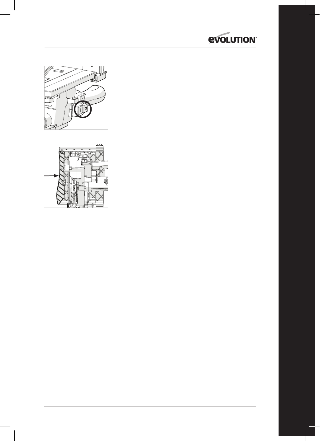
77
www.evolutionpowertools.com
FR
OPÉRATIONS DE BASE DE LA SCIE SUR TABLE
AVERTISSEMENT: Ne coupez pas de métal ou de matériaux
métalliques lorsque l'appareil est en mode scie sur table.
AVERTISSEMENT: N'essayez jamais de faire des coupes à la
main avec cet appareil. Utilisez toujours un guide de refend
correctement réglé pour minimiser le risque de blocage et de
rebond de la lame.
AVERTISSEMENT: Cet appareil n'a pas été conçu pour couper
des feuillures ou des rainures renforcées.
Remarque: Un dispositif d'extraction de poussière pour atelier
peut être branché à l'orifice d'extraction, sur le côté gauche de
l'appareil, si nécessaire.
1. Interrupteurs marche/arrêt de la scie sur table (Ill. 20)
• Appuyez sur le bouton vert (I) pour démarrer le moteur.
• Appuyez sur le bouton rouge (O) pour arrêter le moteur.
2. Coupe longitudinale
Remarque: Vérifiez que le guide de refend soit fixé en place et
soit parallèle à la lame de la scie. Vérifiez que le couteau fendeur
soit bien aligné par rapport à la lame de la scie.
Lorsque vous coupez une petite section, vous devriez utiliser un
poussoir pour alimenter/guider les 300 derniers mm du matériau
à travers la lame. Un poussoir devrait toujours être utilisé lors de
l'exécution de coupes de moins de 300 mm.
Remarque: Un poussoir est fourni avec la R210MTS-G2 et dispose
d'un emplacement de rangement dédié à l'avant de l'appareil.
Nous recommandons de ranger le poussoir sur l'appareil lorsqu'il
n'est pas utilisé. (Ill. 21)
Lorsque vous coupez des panneaux longs ou larges, utilisez
toujours un support de travail éloigné ou demandez de l'aide à un
professionnel.
Ne placez jamais les mains devant la lame.
Remarque: Si le poussoir est endommagé, il devrait être
remplacé.
CONTRÔLE ET RÉGLAGE DES ANGLES DE BISEAU
AVERTISSEMENT: Avant d'effectuer tout réglage, assurez-
vous que l'appareil est débranché de l'alimentation électrique.
Remarque: Bien que tous les réglages des angles aient été
effectués en usine, une vérification et un réglage peuvent être
nécessaires en raison de l'usure normale de fonctionnement.
Remarque: Pour vérifier et régler les angles de biseau, l'appareil
doit être en configuration scie à onglets.
Ill.20
Ill.21

78
www.evolutionpowertools.com
ANGLE DU BISEAU À 0˚
À l'angle de biseau 0˚, la lame doit être perpendiculaire et à
exactement 90˚ par rapport au plateau rotatif. Une équerre
précise d’ingénieur (non fournie) est nécessaire pour vérifier
l'angle de biseau de 0˚.
À vérifier:
•
Vérifiez que la tête de coupe est en position verticale, contre sa
butée, avec le pointeur de biseau indiquant l'angle de biseau 0˚.
• Serrez la poignée de verrouillage du biseau.
• Abaissez la tête de coupe dans sa position la plus basse.
Verrouillez en place à l'aide de la broche de verrouillage de la
tête et relevez manuellement le protège-lame inférieur.
• L'équerre d'ingénieur peut maintenant être utilisée pour vérifier
l'angle entre la lame et le plateau rotatif.
Si un réglage est nécessaire:
Remarque: La tête de coupe devra être inclinée pour avoir accès
à la vis de réglage de la butée de biseau de 0˚.
• La tête de coupe devra être inclinée pour avoir accès à la vis de
réglage de la butée de biseau de 0˚. (Ill. 22)
• Utilisez une clé Allen pour tourner la vis de butée de biseau
dans le sens des aiguilles d'une montre ou dans le sens inverse,
selon les besoins.
• Lorsque l'alignement exact entre la lame
et le plateau rotatif est atteint, serrez le contre-écrou.
ANGLE DU BISEAU À 45˚
L'angle de biseau de 45˚ peut être vérifié de la même manière que
l'angle de biseau de 0˚. Une équerre d'ingénieur précise de 45˚
(non fournie) est nécessaire.
À vérifier:
• Vérifiez que la tête de coupe est inclinée à la position 45°,
contre sa butée, avec le pointeur de biseau indiquant
45˚ d'angle de biseau.
• Serrez la poignée de verrouillage du biseau.
• Abaissez la tête de coupe dans sa position la plus basse.
Verrouillez en place à l'aide de la broche de verrouillage de la
tête et relevez manuellement le protège-lame inférieur.
• Utilisez l'équerre d’ingénieur de 45˚ pour vérifier l'angle entre
la lame et le plateau rotatif.
Si un réglage est nécessaire:
Remarque: La tête de coupe devra être inclinée pour pouvoir
accéder à la vis de réglage de la butée de biseau de 45˚.
• Desserrez légèrement le contre-écrou de la vis de réglage de la
butée de biseau 45˚. (Ill. 23)
• Utilisez une clé hexagonale pour tourner la vis de butée de
biseau dans le sens des aiguilles d'une montre ou dans le sens
inverse, selon les besoins.
• Lorsque l'alignement exact entre la lame et le plateau rotatif est
atteint, serrez le contre-écrou.
Ill.22
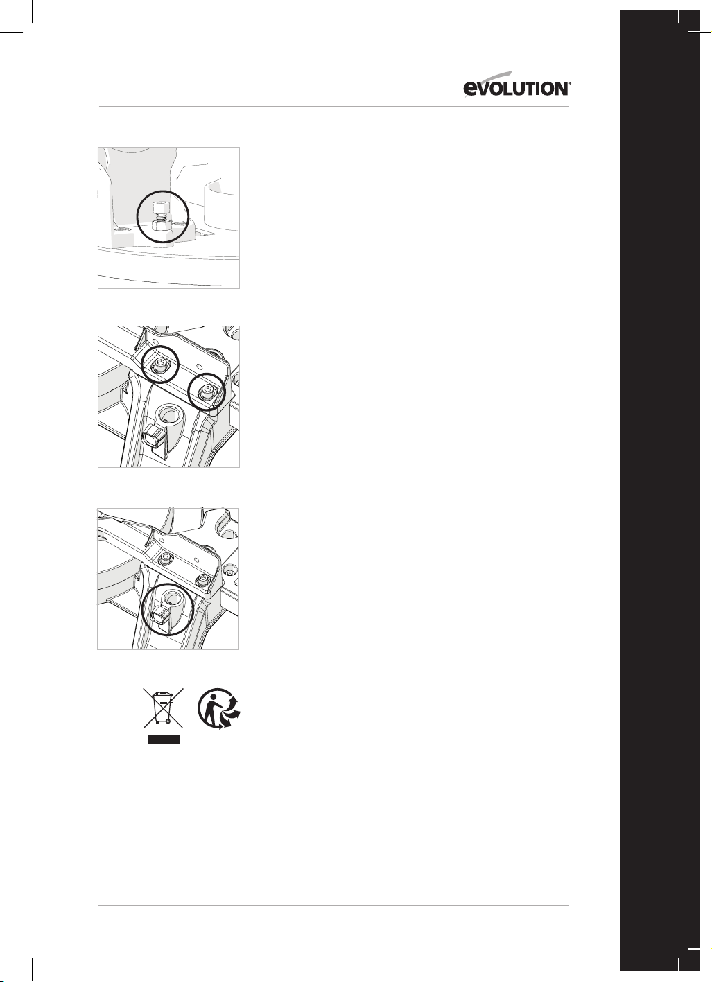
79
www.evolutionpowertools.com
FR
RÉGLAGE DU GUIDE (Ill. 24a et 24b)
Le guide est fixé à la base de l'appareil par quatre vis à tête creuse,
deux de chaque côté. Ces vis sont situées dans des trous allongés,
ce qui permet de repositionner le guide selon les besoins.
Le guide doit être réglé à exactement 90˚ par rapport à une lame
correctement installée. Une équerre d'ingénieur (non fournie) sera
nécessaire pour positionner précisément le guide.
Repositionnement du guide:
• Réglez le plateau rotatif sur l'angle d'onglet 0˚.
• Réglez la tête de coupe sur l'angle de biseau 0˚.
• Desserrez légèrement les quatre vis à tête creuse du guide.
• Abaissez la tête de coupe dans sa position la plus basse.
• Vérifiez l'alignement du guide avec la lame à l'aide de l'équerre
d'ingénieur.
• Alignez le guide si nécessaire, puis serrez les vis à tête creuse.
ENTRETIEN ET RÉGLAGES
AVERTISSEMENT: Veillez à ce que l'appareil soit débranché de la
prise électrique avant tout travail d'entretien ou de réglage.
Nettoyage
Après chaque utilisation, l'appareil devrait être nettoyé. Éliminez
toute sciure, etc., des parties visibles de l'appareil avec un
aspirateur. Un aspirateur peut également être branché à l'orifice
d'extraction de poussière de l'appareil à l'arrière de l'appareil.
Celui-ci devrait éliminer les débris à l'intérieur de l'appareil.
N'utilisez jamais de solvants pour nettoyer les pièces en plastique,
car ils pourraient les endommager. Procédez uniquement au
nettoyage avec un chiffon doux légèrement humide.
Afin de prolonger la durée de vie de l'outil, lubrifiez les pièces
rotatives une fois par mois. Ne lubrifiez pas le moteur. Pour
nettoyer le plastique, n'utilisez pas de produits corrosifs.
AVERTISSEMENT: L’outil ne doit jamais être mis en contact avec
de l’eau.
PROTECTION DE L’ENVIRONNEMENT
Les produits électriques ne doivent pas être jetés avec les ordures
ménagères. Veuillez les recycler lorsque les infrastructures le
permettent. Contactez votre municipalité ou votre revendeur pour
obtenir des conseils sur le recyclage.
Ill.23
Ill. 24a
Ill. 24b
80
www.evolutionpowertools.com
DÉCLARATION CE DE CONFORMITÉ
Le fabricant du produit couvert par cette déclaration est :
RU: Evolution Power Tools Ltd. Venture One, Longacre Close, Holbrook Industrial Estate, Sheeld, S20 3FR.
FR: Evolution Power Tools SAS. 61 Avenue Lafontaine, 33560, Carbon-Blanc, Bordeaux, France.
Le fabricant déclare par les présentes que l'appareil, comme décrit dans la présente déclaration, satisfait à l'ensemble des
dispositions pertinentes de la directive machines et aux autres directives appropriées comme listées ci-après.
Le fabricant déclare en outre que l'appareil, comme décrit dans la présente déclaration, satisfait aux dispositions
pertinentes des exigences essentielles de santé et de sécurité.
Les directives couvertes par cette déclaration sont comme listées ci-après :
2006/42/CE. Directive machines.
2014/30/UE. Directive relative à la compatibilité électromagnétique
Limitation de l'utilisation de certaines substances dangereuses
dans les équipements électriques (directive RoHS)
2012/19/UE. Directive relative aux déchets d'équipements électriques et électroniques (DEEE).
Conforme aux dispositions prévues par les documents suivants :
EN 61029-1:2009+A11• EN 61029-2-11:2012+A11• EN 55014-1:2017+A11:2020 •
EN IEC 55014-1:2021 • EN IEC 55014-2:2021 • EN IEC 61000-3-2:2019+A1 •
EN IEC 61000-3-11:2019
EC type approval to 2006/42/EC Article 12 Section 3b Machinery
TÜV Rheinland LGA Products GmbH - Tillystraße 2 - 90431 Nürnberg
No.: 0197 Reg. No.: BM 50592380 0001
Détails du produit
Description: SCIE SUR TABLE/MULTI-MATÉRIAUX 210mm R210MTS G2
Modèle Evolution n°: 116-0001, 116-0002, 116-0003, 116-0004
Nom du fabricant : EVOLUTION
Tension : 220-240V ~ 50Hz
Entrée : 1500W
La documentation technique requise pour prouver que le produit est conforme aux exigences des directives a été
compilée et est disponible à toute inspection par les autorités concernées chargées de faire appliquer la législation, et elle
montre que notre dossier technique contient les documents listés ci-dessus et que le produit présenté ci-dessus respecte
les normes standards qui y sont mentionnées.
Nom et adresse du détenteur de la documentation technique.
Signature : Nom : Barry Bloomer
Directeur de la chaîne logistique et de
l’approvisionnement
Date : 08/02/2022
RU: Evolution Power Tools Ltd. Venture One, Longacre Close, Holbrook Industrial Estate, Sheeld, S20 3FR.
FR: Evolution Power Tools SAS. 61 Avenue Lafontaine, 33560, Carbon-Blanc, Bordeaux, France.
2011/65/UE. et
2015/863/UE.

81
www.evolutionpowertools.com
FR

82
www.evolutionpowertools.com
IMPORTANTE
Si prega di leggere attentamente tutte le
istruzioni d’uso e di sicurezza.
Per la propria sicurezza, se sussistono dubbi
circa un qualsiasi aspetto riguardante l’utilizzo
di questa attrezzatura, si prega di contattare
l'assistenza tecnica telefonica al numero indicato
sul sito web di Evolution Power Tools.
La nostra organizzazione internazionale gestisce
diverse linee telefoniche di assistenza. In
alternativa, anche il fornitore del prodotto può
offrire assistenza tecnica.
WEB
www.evolutionpowertools.com
E-MAIL
UK:
customer[email protected]
Stati Uniti:
evolutioninfo@evolutionpowertools.com
GARANZIA
Congratulazioni per l'acquisto di un prodotto
Evolution Power Tools. Si prega di completare
online la registrazione del prodotto così
come illustrato nella brochure acclusa al
presente apparecchio. In tal modo sarà
possibile convalidare il periodo di garanzia
dell’apparecchio tramite il sito web di Evolution
introducendo i propri dati e assicurandosi
un'assistenza immediata qualora necessario.
La ringraziamo sinceramente per aver scelto un
prodotto Evolution Power Tools.
Evolution Power Tools si riserva il diritto di
apportare migliorie e modiche al design dei
prodotti senza preavviso.
Si prega di consultare il documento per la
registrazione della garanzia e/o la confezione per
ulteriori dettagli sui termini e condizioni della
garanzia.

83
www.evolutionpowertools.com
IT
SPECIFICHE
UTENSILE UK/UE
Motore (220-240 V ~ 50 Hz) 1500 W
Velocità a vuoto 3800 min
-1
Peso 13 kg
CAPACITÀ DI TAGLIO UK/UE
Piastra in acciaio dolce - Spessore massimo 3 mm
Piastra in acciaio dolce - Durezza massima 210 HB
MASSIMA CAPACITÀ DI TAGLIO (ALLUMINIO, LEGNO E PVC)
CONFIGURAZIONE TRONCATRICE
REGOLAZIONE BISELLO UK/UE
0° 0° 55 x 120 mm
45° 0° 35 x 120 mm
0° 45° Sinistra 55 x 65 mm
0° 45° Destra 55 x 55 mm
45° 45° Sinistra 35 x 30 mm
45° 45° Destra 35 x 70 mm
MASSIMA CAPACITÀ DI TAGLIO - CONFIGURAZIONE SEGA DA BANCO
CAPACITÀ DI TAGLIO UK/UE
Legno - Spessore massimo 40 mm
DIMENSIONI LAMA UK/UE
Diametro 210 mm
Foro 25.4 mm
Numero denti 20
Intaglio 1.7 mm
DATI RUMOROSITÀ E VIBRAZIONI
Pressione acustica L
P
A 103 dB(A); K=3 dB(A)
Livello potenza acustica L
W
A 116 dB(A); K=3 dB(A)
84
www.evolutionpowertools.com
Le misurazioni del valore dichiarato delle
emissioni acustiche sono state eseguite in
accordo con un metodo di verifica standard
(EN 61029-1, EN 61029-2-11). Esse possono
essere usate per confrontare un utensile con
un altro.
ATTENZIONE: Le emissioni sonore durante
l'uso effettivo possono differenziarsi dai valori
dichiarati in base ai modi in cui l'utensile è
impiegato e soprattutto in base al tipo di
pezzo lavorato.
Si rende necessario identificare misure di
sicurezza che tutelino l'operatore in base
ad una stima dell'esposizione al pericolo
nelle reali condizioni d'uso (prendendo in
considerazione tutti i componenti del ciclo
di funzionamento come le tempistiche
di spegnimento dell'utensile e del suo
funzionamento a vuoto, in aggiunta al tempo
di attivazione)
ETICHETTE E SIMBOLI
ATTENZIONE: Non mettere in funzione il
presente apparecchio qualora le etichette di
sicurezza e/o le istruzioni risultino mancanti o
danneggiate. Contattare Evolution Power Tools
per le etichette sostitutive.
Avvertenza: Tutti o alcuni dei seguenti
simboli possono essere presenti nel manuale
o sul prodotto.
Simbolo Descrizione
V
Volt
A
Ampere
Hz
Hertz
Min
-1
Velocità
~
Corrente alternata
n
o
Velocità a vuoto
Indossare occhiali di sicurezza
Indossare protezioni acustiche
Non toccare
Indossare protezioni antipolvere
Leggere le istruzioni
Certificazione CE
Certificazione UKCA
Attenzione
Smaltimento di apparecchiature
elettriche ed elettroniche
Doppio isolamento
Smaltimento e riciclaggio riuti
secondo la normativa Triman

85
www.evolutionpowertools.com
IT
DESTINAZIONE D'USO
DELL'ELETTROUTENSILE
ATTENZIONE: Il presente prodotto è una
troncatrice combinata a funzionamento
manuale ed è stata progettata per essere
utilizzata con specifiche lame Evolution.
Utilizzare esclusivamente accessori progettati
per l'utilizzo sul presente apparecchio e/o
quelli espressamente raccomandati da
Evolution Power Tools Ltd.
Se equipaggiato con una lama idonea, il
presente utensile può essere utilizzato per
tagliare:
Acciaio dolce
Alluminio
Legno
Materie plastiche
USO NON CONSENTITO
DELL'ELETTROUTENSILE
ATTENZIONE: Il presente prodotto è una
troncatrice combinata a funzionamento
manuale e deve essere utilizzata
esclusivamente come tale. Esso non deve in
alcun modo essere modificato, o utilizzato per
alimentare qualunque altro apparecchio o
manovrare un qualunque accessorio differente
da quelli identificati nel presente manuale di
istruzioni.
ATTENZIONE: Il presente utensile non è
progettato per essere impiegato da persone
(bambini inclusi) con capacità fisiche,
sensoriali o mentali ridotte, o da utenti privi
di esperienza e conoscenza, a meno che
essi non siano supervisionati o istruiti circa il
suo utilizzo in sicurezza da un responsabile
competente in tal senso.
Si consiglia di controllare che i bambini non
abbiano accesso al presente utensile e che non
abbiano la possibilità di giocarci.
SICUREZZA ELETTRICA
Il presente utensile è dotato di un modello di
presa elettrica e di un cavo di alimentazione
idonei al mercato di destinazione. Qualora il
cavo di alimentazione sia danneggiato, esso
deve essere sostituito da un cavo specifico
o da uno assemblato appositamente dal
produttore o dal suo servizio di assistenza.
USO ESTERNO
ATTENZIONE: Per la propria sicurezza,
qualora il presente apparecchio sia utilizzato
all'aperto, non deve essere esposto alla
pioggia o impiegato in ambienti umidi.
Non posizionare l'utensile su superfici umide.
Utilizzare un banco da lavoro asciutto e pulito
se disponibile.
Per una protezione supplementare, utilizzare
un interruttore differenziale (R.C.D.) che
interrompa l'alimentazione qualora la
dispersione di corrente a terra superi i 30 mA
per 30 ms. Verificare sempre il funzionamento
dell'interruttore differenziale (R.C.D.) prima di
utilizzare l'utensile.
Qualora sia necessario un cavo di prolunga,
esso deve essere di tipo idoneo all'utilizzo
esterno e contrassegnato di conseguenza.
Quando si utilizza un cavo di prolunga, devono
essere rispettate le istruzioni del produttore.
ISTRUZIONI GENERALI SULLA SICUREZZA
DEGLI UTENSILI ELETTRICI
• Seguire per intero le seguenti istruzioni
prima e durante l'utilizzo dell'utensile.
• Conservare le presenti istruzioni in un luogo
sicuro.
• Evitare il contatto del corpo con parti
dotate di messa a terra.
• Quando un utensile è inattivo, deve essere
conservato in luogo asciutto e sicuro,
lontano dalla portata dei bambini.
• Il lavoro sarà più semplice e sicuro
mantenendo i propri utensili puliti e affilati.
Verificare con cadenza regolare il cavo di
alimentazione e farlo sostituire da tecnico
autorizzato al primo segno di danno.
• Controllare regolarmente i cavi di prolunga
e sostituirli se danneggiati.
• In caso di lavoro in ambiente esterno,
utilizzare esclusivamente cavi di prolunga
approvati per tale scopo e contrassegnati di
conseguenza.
• Concentrarsi sul proprio lavoro. Adottare
logica e buon senso durante il suo
svolgimento. Non lavorare mai in caso di
stanchezza.
• Mai utilizzare un utensile che non sia
possibile accendere e spegnere.
• Attenzione! L'utilizzo di accessori e
estensioni ad innesto diversi da quelli
previsti può esporre al rischio di infortunio.
• L'utensile è dotato di un interruttore di
sicurezza che ne previene la riaccensione
accidentale a seguito di black-out (nella
modalità sega da banco).
• Non utilizzare mai la sega per tagliare
legname a sezione circolare.
• Verificare il cavo di alimentazione. Non
utilizzare mai un cavo di alimentazione
difettoso o danneggiato.
• Non tirare il cavo per estrarre la spina dalla
presa di alimentazione. Proteggere il cavo

86
www.evolutionpowertools.com
da fonti di calore, olio e bordi affilati.
• Raccomandiamo di indossare scarpe anti-
scivolo durante lavorazioni in esterno.
• Raccogliere i capelli lunghi in un'apposita
retina.
• Evitare posture anomale.
• Un'area di lavoro disordinata può essere
fonte di incidenti.
• Non consentire a estranei, in particolare
bambini, di toccare l'utensile o il cavo di
alimentazione. Tenerli lontani dal proprio
ambiente di lavoro.
• Il coltello separatore è un importante
dispositivo di sicurezza. Non solo guida il
pezzo in lavorazione, ma evita inoltre che
l'intaglio si chiuda dietro la lama e che ciò
generi un effetto di contraccolpo. Fare
attenzione allo spessore del separatore, il
suo profilo non deve mai essere più sottile
di quello del corpo lama o superare la
larghezza dell'intaglio di quest'ultima.
• Il coprilama superiore deve essere
abbassato sul pezzo in lavorazione in
occasione di ogni taglio.
• Accertarsi di impiegare uno spingipezzo
mentre si accompagnano al taglio pezzi
inferiori ai 120 mm di larghezza o un
tampone di avanzamento per pezzi inferiori
ai 30 mm di larghezza.
IMPORTANTE: Non utilizzare mai la presente
troncatrice per eseguire tagli dal pieno.
• Posizionarsi sempre a lato della lama
durante l'utilizzo della troncatrice.
• Accertarsi che gli scarti non si fermino sulla
corona della lama per evitare che siano poi
espulsi verso l'area circostante.
• Se l'area di taglio presenta usura, sostituire
l'inserto del banco.
• Per prevenire infortuni derivanti da
segatura e trucioli, utilizzare la troncatrice
esclusivamente con un sistema aspiratore
adeguato o del tipo standard industriale.
• Scollegare sempre dall'alimentazione prima
di regolare o riparare l'utensile.
• Impartire le medesime regole di sicurezza a
chiunque utilizzi l'utensile.
• Non utilizzare la presente sega per tagliare
legna da ardere.
• Attenzione! Mani e dita possono subire
infortuni a causa della lama rotante.
• Per il primo utilizzo dell'utensile, verificare
che la tensione di alimentazione riportata
sulla targhetta informativa sia la stessa di
quella di rete.
• In caso sia necessario un cavo di prolunga,
accertarsi che la sezione del conduttore
sia sufficiente al fabbisogno elettrico della
sega. Sezione minima: 1,0 mm2.
• In caso si utilizzi una bobina di cavo, l'intero
cavo deve essere srotolato da essa.
• Non trasportare mai la sega tramite il suo
cavo.
• Non esporre la sega alla pioggia e non
utilizzarla in condizioni umide o bagnate.
• Fornire buona illuminazione.
• Mai operare con la sega vicino a liquidi o
gas combustibili.
• Indossare adeguato vestiario di lavoro.
Indumenti o gioielli larghi possono
rimanere intrappolati nella lama in
rotazione.
• Gli operatori devono avere almeno 18 anni
di età. Gli apprendisti di almeno 16 anni
possono utilizzare l'utensile esclusivamente
se supervisionati.
• Tenere i bambini lontani dall'utensile
quando è collegato all'alimentazione.
IMPORTANTE:
• Verificare il cavo di alimentazione. Non
utilizzare mai un cavo di alimentazione
difettoso o danneggiato.
• Tenere il proprio posto di lavoro sgombro
da scarti di legno e oggetti non necessari.
• Le persone che lavorano con l'utensile non
devono essere distratte.
• Fare attenzione alla direzione di rotazione
del motore e della lama.
• Dopo lo spegnimento del motore, non
rallentare mai la lama applicando pressione
sul suo lato.
• Impiegare esclusivamente lame ben affilate
e che non presentino crepe o deformazioni.
• L'utensile deve essere utilizzato
esclusivamente con dispositivi conformi alla
normativa EN 847-1
• Le lame difettose devono essere
immediatamente sostituite.
• Non utilizzare mai lame non conformi ai
dati riportati sul presente manuale.
• Accertarsi che la freccia riportata sulla lama
combaci con quella indicata sull'utensile.
• Accertarsi che la lama non entri in
contatto con il banco girevole in alcuna
impostazione. Per tale operazione,
scollegare l'utensile e girare a mano la lama
nelle posizioni a 45° e a 90°. Se necessario,
regolare nuovamente la testa di taglio.
• È obbligatorio accertarsi che tutti i
dispositivi usati per coprire la lama siano in
buone condizioni di funzionamento.
• Mai incastrare la copertura a cardini della
lama in posizione aperta.

87
www.evolutionpowertools.com
IT
INDICAZIONI SANITARIE
ATTENZIONE: Durante l'utilizzo dell'utensile, si
possono produrre particelle di polvere. In alcune
circostanze, a seconda del materiale sul quale
si sta lavorando, tali polveri possono risultare
particolarmente dannose. Qualora si abbia il
sospetto che la vernice presente sulla superficie
del materiale sul quale si sta operando contenga
piombo, richiedere una consulenza professionale.
Le vernici a base di piombo devono essere
rimosse esclusivamente da professionisti. Si
sconsiglia fortemente di provare a farlo in prima
persona. Una volta che la polvere si è depositata
sulla superficie, il contatto tra mani e bocca può
causare l'ingestione di piombo.
L'esposizione a livelli anche ridotti di piombo può
causare danni neurologici e al sistema nervoso
irreversibili. Bambini e feti sono particolarmente
sensibili a tale pericolo. Si consiglia di prendere in
considerazione i pericoli associati ai materiali sui
quali si opera e di ridurre il rischio
di esposizione a essi. Dato che alcuni materiali
possono generare polveri pericolose per la salute,
si raccomanda di indossare una mascherina
facciale certificata con filtri sostituibili durante
l'utilizzo
del presente utensile.
È sempre necessario:
• operare in un'area ben ventilata.
• Lavorare con materiale di sicurezza approvato,
come maschere antipolvere specificamente
progettate per filtrare particelle microscopiche.
ATTENZIONE: il funzionamento di qualunque
utensile elettrico può comportare il rischio che
un oggetto estraneo sia scagliato verso gli occhi,
causando lesioni oculari gravi. Prima di iniziare a
utilizzare un utensile elettrico, indossare sempre
occhiali di protezione o occhiali di sicurezza
con protezioni laterali o una maschera facciale
completa quando necessario.
ISTRUZIONI DI SICUREZZA AGGIUNTIVE -
TRONCATRICI
Le seguenti istruzioni specifiche di sicurezza
relative alle troncatrici si basano sui requisiti della
normativa EN 61029-2-11
SICUREZZA DELLA LAMA
ATTENZIONE: Le lame circolari rotanti sono
estremamente pericolose e possono essere causa
di lesioni gravi e amputazioni. Tenere sempre e in
qualunque circostanza le dita e le mani ad almeno
150 mm dalla lama. Non tentare in alcun caso
di recuperare il materiale tagliato fin quando la
testa da taglio non sia in posizione sollevata, la
protezione coprilama completamente chiusa e la
lama stessa abbia smesso di muoversi.
Utilizzare esclusivamente lame raccomandate dal
produttore, come illustrato nel manuale, e che si
attengano ai requisiti della normativa
EN 847-1.
Non utilizzare lame che siano danneggiate o
deformate dato che potrebbero frantumarsi
causando gravi lesioni all'operatore o ai presenti.
Non utilizzare lame in acciaio ad alta velocità
(HSS).
Se l'inserto del banco risulta danneggiato o
usurato, esso deve essere sostituito con uno
identico disponibile dal produttore come da
specifiche nel presente manuale.
DISPOSITIVI DI PROTEZIONE
INDIVIDUALE (DPI)
È necessario indossare protezioni acustiche per
ridurre il rischio di perdita dell'udito.
È necessario indossare protezioni per gli occhi
per prevenire l'eventualità di perdita della vista a
causa dei trucioli espulsi.
È consigliato inoltre l'utilizzo di protezioni
respiratorie dato che alcuni tipi di legno e di
prodotti a base di legno, specialmente l'MDF
(Medium Density Fibreboard), possono produrre
polveri potenzialmente pericolose per la salute.
Si raccomanda, durante l'utilizzo del presente
utensile, di usare una mascherina per naso e
bocca con filtri sostituibili, oltre all'utilizzo del
dispositivo di aspirazione della polvere.
È necessario indossare guanti quando si
maneggiano lame o materiali grezzi. Si
raccomanda che le lame, quando possibile, siano
trasportate in una custodia apposita. Non è
consigliato indossare guanti quando si adopera
la troncatrice.
FUNZIONAMENTO IN SICUREZZA
Accertarsi sempre di aver selezionato la lama
corretta in funzione del materiale da tagliare.
Non utilizzare la presente troncatrice per tagliare
materiali differenti da quelli specificati nel
manuale di istruzioni.
Quando si trasporta una troncatrice assicurarsi
sempre che la testa da taglio sia bloccata a
90° verso il basso (nel caso di una troncatrice
scorrevole assicurarsi che le barre di scorrimento
siano bloccate). Sollevare l'apparecchio afferrando
i bordi esterni della base con entrambe le mani
(nel caso di una troncatrice scorrevole, utilizzare

88
www.evolutionpowertools.com
le maniglie in dotazione). In nessuna circostanza
l'apparecchio deve essere sollevato o trasportato
tramite la protezione retrattile o tramite alcuna
parte del suo meccanismo di funzionamento.
Prima di ogni utilizzo, verificare il funzionamento
della protezione retrattile e il suo meccanismo
di funzionamento accertandosi che non siano
presenti danni, e che tutte le parti in movimento
operino regolarmente e in modo corretto.
Tenere il banco da lavoro e il pavimento dell'area
sgombro da detriti, inclusi segatura, trucioli e
scarti.
Verificare e assicurarsi sempre che la velocità
contrassegnata sulla lama sia almeno uguale alla
velocità a vuoto riportata sulla troncatrice.
In nessuna circostanza si deve utilizzare una lama
con una velocità nominale inferiore a quella a
vuoto riportata sulla troncatrice.
Laddove sia necessario utilizzare uno spaziatore
o degli anelli riduttori, essi dovranno essere
idonei all'uso previsto ed esclusivamente del tipo
raccomandato dal produttore.
La lama deve essere sostituita esclusivamente
come illustrato nel manuale di istruzioni.
Non tentare in alcun caso di recuperare scarti o
altra parte del pezzo in lavorazione fin quando la
testa da taglio non sia in posizione sollevata, la
protezione coprilama completamente chiusa e la
lama stessa abbia smesso di muoversi.
EFFETTUARE TAGLI IN MANIERA CORRETTA
E SICURA
Quando possibile bloccare sempre il pezzo
da lavorare al banco tramite morsetto, se in
dotazione.
Assicurarsi sempre che prima di ogni taglio la
troncatrice sia montata in una posizione stabile.
Se necessario la troncatrice può essere montata
su una base in legno, su banco da lavoro o
collegata a un supporto dedicato per troncatrice
come illustrato nel presente manuale.
I pezzi da lavorare di lunghe dimensioni devono
essere sostenuti da supporti da lavoro forniti o da
adeguati supporti supplementari.
ATTENZIONE: In caso vi siano delle parti
mancanti, non mettere in funzione il proprio
apparecchio fin quando esse non siano state
sostituite. Il mancato rispetto della presente
regola può comportare gravi lesioni.
INDICAZIONI SUPPLEMENTARI DI SICUREZZA
TRASPORTO DELLA TRONCATRICE DA BANCO
Indicazioni di sicurezza
• Sebbene compatto, il presente utensile è
pesante. Per ridurre il rischio di infortuni alla
schiena, richiedere un aiuto adeguato ogni
volta che sia necessario
sollevare la troncatrice.
• Per ridurre il rischio di infortuni alla schiena,
tenere l'utensile vicino al proprio corpo
quando lo si solleva. Piegare le ginocchia
in maniera da sollevare il peso con le proprie
gambe, non con la schiena. Sollevarla
utilizzando le aree di presa presenti su ogni
lato della base dell'utensile.
• Non trasportare mai la troncatrice tramite il
cavo di alimentazione. Trasportare l'utensile
tramite il cavo di alimentazione può causare
danni all'isolamento dei fili di connessione con
il rischio di scosse elettriche e incendio.
• Prima di spostare la sega, stringere le viti di
bloccaggio bisello e smusso per prevenire
movimenti inaspettati e improvvisi.
• Bloccare la testa da taglio nella sua
posizione più bassa. Assicurarsi che il
perno di bloccaggio della testa da taglio
sia completamente inserito nel proprio
alloggiamento.
ATTENZIONE: Non utilizzare la protezione
coprilama come "punto di sollevamento". Il cavo
di alimentazione deve essere sconnesso dalla
fonte di corrente prima di spostare l'apparecchio.
• Bloccare la testa da taglio verso il basso
utilizzando il perno di bloccaggio della testa
stessa.
• Allentare la vite di bloccaggio dell'angolo di
bisello. Portare il banco alle impostazioni di
massima estensione su ogni lato.
• Bloccare il banco in posizione utilizzando la
vite di bloccaggio.
• Per il trasporto, utilizzare le due apertura da
impugnatura ricavate su ogni lato della base
dell'utensile.
Posizionare la sega su una superficie sicura
e ben ferma e verificare attentamente
l'apparecchio.
Verificare in particolar modo il funzionamento
delle funzioni di sicurezza dell'utensile prima di
cominciare a utilizzarlo.
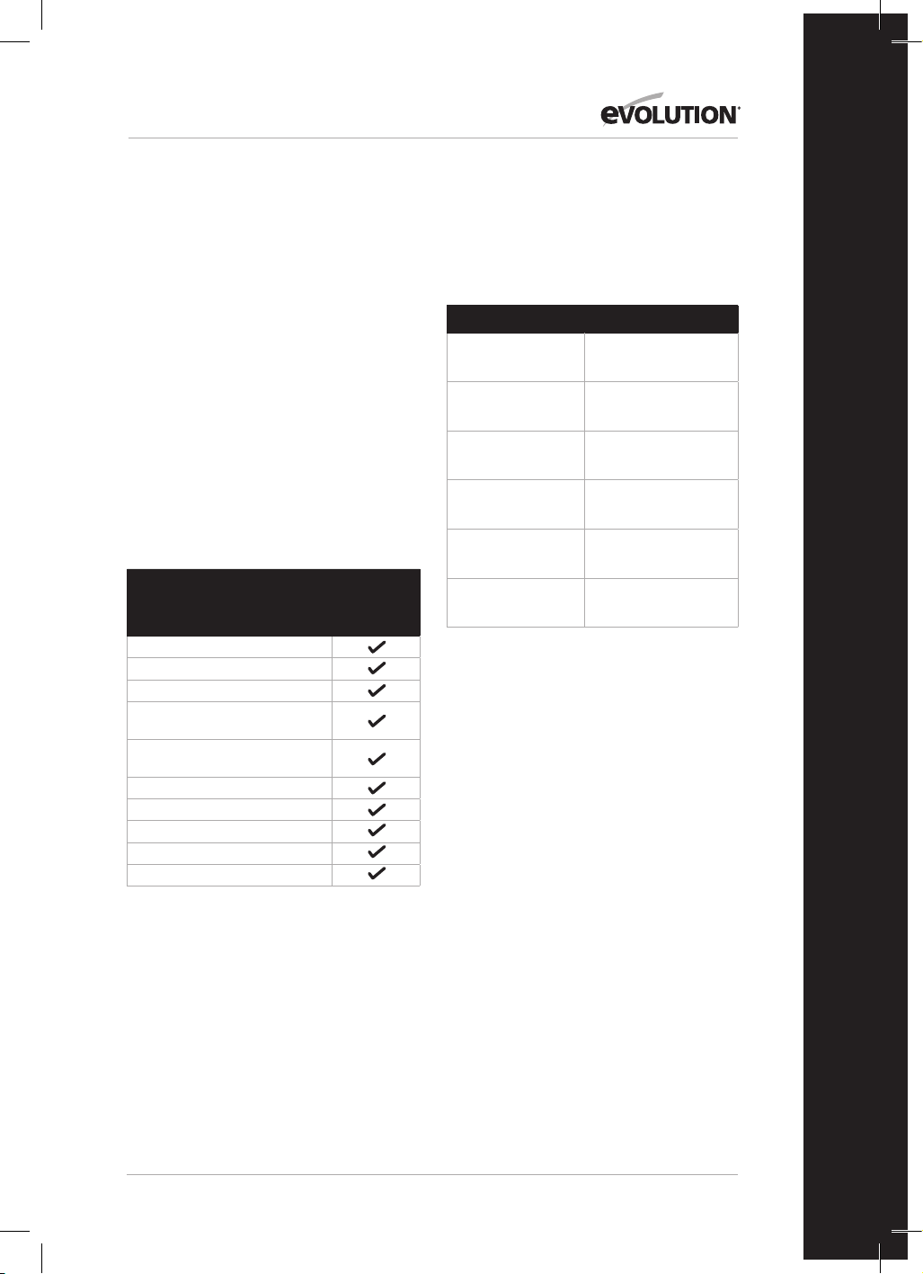
89
www.evolutionpowertools.com
IT
INFORMAZIONI INTRODUTTIVE -
DISIMBALLAGGIO
Attenzione: Il pacco contiene oggetti taglienti.
Prestare attenzione durante l'apertura.
Rimuovere l'apparecchio insieme agli accessori
inclusi nell'imballo. Controllare attentamente che
l'apparecchio sia in buone condizioni e verificare
che siano presenti tutti gli accessori elencati nel
presente manuale.
Accertarsi inoltre che tutti gli accessori siano
completi in ogni loro parte. Qualora si riscontrino
parti mancanti, l'apparecchio e i suoi accessori
devono essere restituiti al rivenditore insieme
all'imballo originale. Non gettare via l'imballo.
Conservarlo intatto per la durata del periodo
di garanzia. Smaltire il materiale d'imballaggio
in maniera eco-responsabile. Riciclare laddove
possibile. Non consentire ai bambini di giocare
con le buste di plastica vuote a causa del rischio di
soffocamento.
COMPONENTI IN DOTAZIONE
Descrizione
116-0001,
116-0002,
116-0003,
116-0004
Manuale di istruzioni
Morsetto di bloccaggio
Spingipezzo
Chiave a perno
(Sostituzione lama)
Chiave esagonale a doppia
testa 6-5 mm
Lama multiuso
La battuta longitudinale
Sacchetto per la polvere
Coprilama banco
Estensioni laterali della base x 2
ACCESSORI SUPPLEMENTARI
In aggiunta ai componenti standard forniti
unitamente all'utensile, sono disponibili anche i
seguenti accessori sul negozio online di Evolution
all'indirizzo
www.evolutionpowertools.com o tramite il vostro
distributore locale.
Descrizione Parte N.
RAGE Multi-materiale
TCT Lama
RAGEBLADE210MULTI
Lama da legno
generico da 210 mm
GW210TCT-30
Lama da legno
generico da 210 mm
FW210TCT-40
Lama diamantata
da 210 mm
D210CON
Supporto per
troncatrice
005-0001
Supporto per
troncatrice +
005-0005
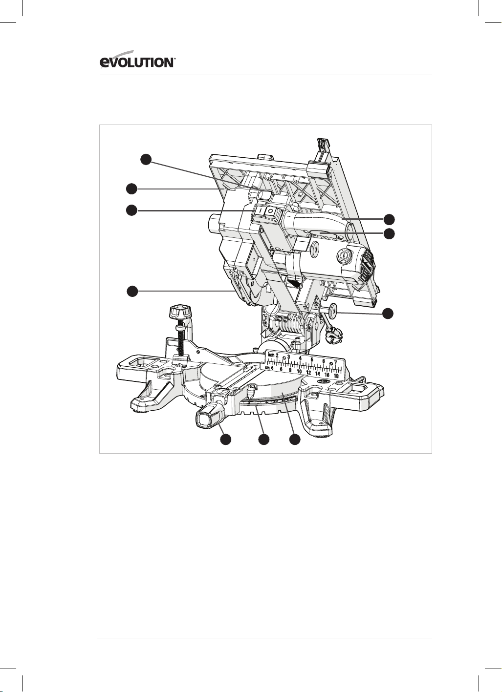
90
www.evolutionpowertools.com
R210MTS-G2 PANORAMICA DELL’UTENSILE
1
3
8
1. IMPUGNATURA DA TAGLIO
2. BANCO GIREVOLE
3. COPRILAMA INFERIORE RETRATTILE
4. MANOPOLA DI BLOCCAGGIO ANGOLO DI
BISELLO
5. SCALA ANGOLATURA BISELLO
6. LEVA DI RILASCIO TESTA DA TAGLIO
7. PERNO DI BLOCCAGGIO TESTA DA TAGLIO
8. ALLOGGIAMENTO DELLO SPINGIPEZZO
9. INTERRUTTORE ON/OFF DELLA SEGA DA
BANCO
10. INTERRUTTORE A PRESSIONE ON/OFF
DELLA TRONCATRICE
2
9
10
4
6
5
7

91
www.evolutionpowertools.com
IT
R210MTS-G2 PANORAMICA DELL’UTENSILE
1. PIANO DEL BANCO
2. PROTEZIONE DELLA SEGA DA BANCO
3. BATTUTA LONGITUDINALE
4. SPINGIPEZZO
5. MODALITÀ PERNO BANCO/TRONCATRICE
6. LEVA BLOCCO SMUSSO
7. BRACCIO STABILIZZANTE POSTERIORE
8. SOSTEGNI DEL PEZZO DA LAVORARE (X2)
9. CONSERVAZIONE DEGLI STRUMENTI IN
DOTAZIONE
10. LEVE DI BLOCCO DELLA BATTUTA
LONGITUDINALE (X2)
11. SCALE DI MISURA PIANO SUPERIORE DEL
BANCO
2
4
3
1
7
8
9
5
6
10
10
11
11

92
www.evolutionpowertools.com
GUIDA INTRODUTTIVA
ATTENZIONE: SCOLLEGARE SEMPRE LA SEGA DALLA FONTE DI
ALIMENTAZIONE PRIMA DI ESEGUIRE QUALUNQUE REGOLAZIONE.
MONTAGGIO PERMANENTE DELLA SEGA DA BANCO/
TRONCATRICE R210MTS-G2 (Fig. 1)
ATTENZIONE: Per ridurre il rischio di infortuni causati da movimenti
imprevisti della sega, posizionare la stessa nella postazione
desiderata su un banco da lavoro o su altro tipo di cavalletto
raccomandato. La base della sega ha quattro fori per montare la
troncatrice. Qualora l'utilizzo della sega sia previsto in un'unica
postazione, ancorarla in maniera permanente al banco da lavoro o
cavalletto tramite bulloni con rondelle e dadi di blocco.
1. Stringere i blocchi di smusso e di bisello.
2. Posizionare l'utensile in modo tale che nessuno possa mettersi
dietro di esso. I detriti espulsi potrebbero infatti ferire i passanti.
3. Collocare la sega su una superficie salda e in piano dove sia
garantito molto spazio per lo spostamento e l'adeguato sostegno dei
pezzi da lavorare.
4. Sostenere la sega in maniera tale che il banco sia in piano e la sega
non oscilli.
5. Imbullonare o bloccare con morsetti la sega al suo supporto.
BARRA STABILIZZANTE POSTERIORE
Estendere la barra al lato posteriore dell'utensile (Fig. 2)
PROTEZIONE DELLA SEGA DA BANCO
Per installare il coprilama della sega da banco:
• Allentare le 2 viti a testa esagonale con la chiave esagonale
• Inserire l'unità coprilama della sega da banco (Fig. 3)
• Serrare le 2 viti esagonali
INSTALLAZIONE/RIMOZIONE DELLA LAMA
ATTENZIONE: Utilizzare esclusivamente lame originali Evolution
progettate per l'utilizzo sul presente utensile. Accertarsi che la
velocità massima della lama sia compatibile con quella dell'utensile.
Effettuare la presente procedura esclusivamente con l'utensile
disconnesso dalla fonte di alimentazione.
Avvertenza: Si consiglia all'operatore di valutare l'utilizzo di guanti
protettivi mentre maneggia la lama nelle fasi di installazione o
sostituzione della stessa.
Per sostituire una lama:
• Estrarre il perno (Fig. 4) per sbloccare il motore.
• Esercitare una leggera pressione verso il basso sull'impugnatura
della testa da taglio.
• Estrarre il perno di bloccaggio della testa da taglio e consentire a
quest'ultima di sollevarsi nella sua posizione di altezza massima.
(Fig. 5)
• Utilizzare la chiavetta da perno (in dotazione) per tenere la flangia
esterna della lama.
• Utilizzare la chiave esagonale (in dotazione) per svitare la vite del
mandrino. (Fig. 6)
Avvertenza: La vite del mandrino è dotata di filettatura a sinistra.
Girare in senso orario per svitare e in senso antiorario per stringere.
• Rimuovere la vite del mandrino e la flangia esterna della lama.
Fig. 1
1) Bullone a testa
esagonale
2) Rondella a molla
3) Rondella piatta
4) Base troncatrice
5) Banco da lavoro
6) Rondella piatta
7) Rondella a molla
8) Dado esagonale
9) Dado di
bloccaggio
(1)
(2)
(3)
(4)
(5)
(6)
(7)
(8)
(9)
Fig. 2
Fig. 4
Fig. 3
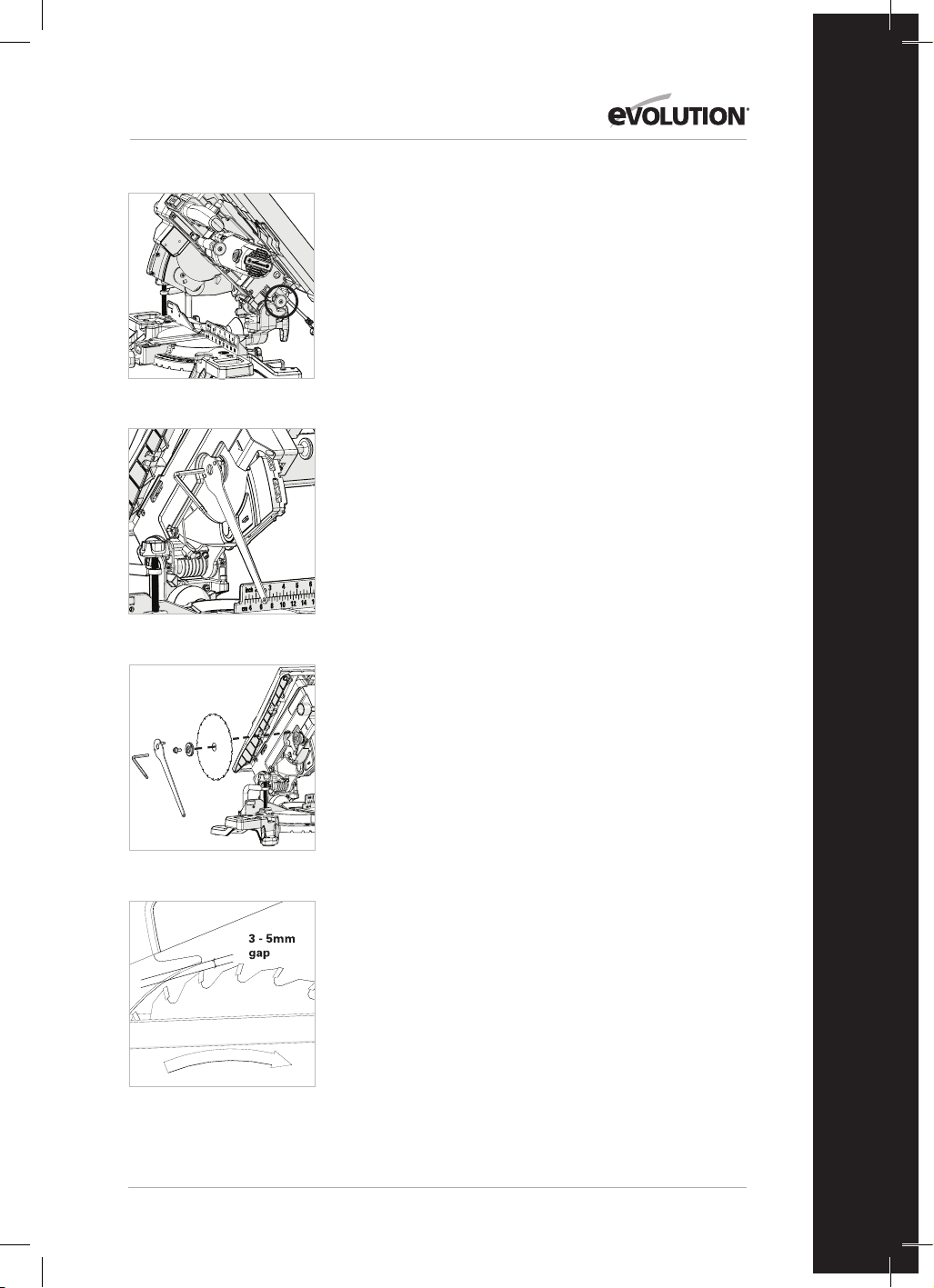
93
www.evolutionpowertools.com
IT
• Ritrarre il coprilama inferiore premendo la leva di rilascio della
testa da taglio e ruotando verso l'alto detto coprilama per esporre
la stessa.
• Rimuovere la lama tirandola verso l'esterno per liberare l'estremità
del mandrino e quindi verso il basso e in avanti per estrarla
dall'utensile. (Fig. 7)
Lama guida separatrice
La lama guida separatrice è un componente molto importante ed è
fornito già installato sul coprilama superiore. Essa evita che il pezzo in
lavorazione si blocchi mentre passa attraverso la lama. Ispezionare la
lama guida regolarmente e sostituirla se usurata o danneggiata.
La lama guida separatrice deve essere regolata in maniera tale che la
distanza tra le punte dei denti della lama e il bordo della lama guida
stessa sia approssimativamente di 3-5 mm. (Fig. 8)
Per regolare la lama guida allentare le due viti di blocco
(Fig. 9) usando delicatamente una chiave a brugola. Quando si
raggiunge il corretto allineamento, serrare le viti.
Avvertenza: Utilizzare esclusivamente un'unità coprilama superiore
originale Evolution, dato che si tratta di un componente specifico per
il presente utensile. I ricambi non originali posso costituire pericolo.
In caso di dubbio, si prega di contattare la linea di assistenza.
PER CONFIGURARE R210MTS-G2 COME TRONCATRICE
ATTENZIONE: Eseguire la presente procedura esclusivamente con
l'utensile disconnesso dalla fonte di alimentazione.
Attenzione: R210MTS-G2 dispone di molti dispositivi integrati di
sicurezza e di blocco. È importante che le seguenti istruzioni siano
lette, comprese e messe in pratica. Una non corretta procedura
di configurazione può arrecare danni all'utensile e/o infortuni
all'operatore.
• Estrarre il perno (Fig. 4) per sbloccare il motore.
• Esercitare una leggera pressione verso il basso sull'impugnatura
della testa da taglio.
• Estrarre il perno di bloccaggio della testa da taglio e consentire a
quest'ultima di sollevarsi nella sua posizione di altezza massima.
(Fig. 5)
R210MTS-G2 è ora pronta per essere usata come troncatrice.
SOSTEGNI DEL PEZZO DA LAVORARE
I sostegni possono essere installati su entrambi i lati della base
dell'utensile (Fig. 10)
MORSETTO DI BLOCCAGGIO
R210MTS-G2 dispone in dotazione di un morsetto di bloccaggio.
Due innesti a incavo (uno per lato) sono incorporati sul retro della
battuta dell'apparecchio. (Fig. 11)
• Inserire la stanga del morsetto nell'innesto che si addice meglio al
tipo di taglio da eseguire, assicurandosi di spingerlo in sede fino in
fondo.
• Serrare la vite della battuta per fissare il perno del morsetto
nell'innesto della battuta stessa.
Fig. 5
Fig. 8
Fig. 6
Fig. 7

94
www.evolutionpowertools.com
• Posizionare il pezzo da lavorare sul banco girevole e contro la
battuta.
• Regolare il morsetto in modo da ancorare saldamente il pezzo da
lavorare al banco girevole.
• Prima di accingersi al taglio, verificare che il morsetto non ostacoli
il percorso della lama mentre si abbassa la testa da taglio.
ISTRUZIONI DI FUNZIONAMENTO IN CONFIGURAZIONE
TRONCATRICE
1. Rilascio della testa da taglio
Avvertenza: In configurazione troncatrice, la testa da taglio sarà
automaticamente bloccata nella sua posizione di altezza massima
con il coprilama inferiore retrattile a coprire del tutto i denti della
lama.
Per rilasciare la testa da taglio, premere e tenere premuta l'apposita
leva di rilascio. (Fig. 12)
Spingere delicatamente verso il basso l'impugnatura della testa da
taglio per abbassare quest'ultima. Il funzionamento del coprilama
inferiore retrattile è automatico, quando a contatto con il pezzo in
lavorazione.
2. Posizionamento di corpo e mani (Fig. 13)
• In nessun caso posizionare le proprie mani nella "no hands zone"
(ad almeno 150 mm dalla lama). Sul banco girevole dell'utensile
sono presenti dei promemoria grafici delle pratiche di lavoro
sicure. Tenere le mani distanti dal percorso della lama.
• Ancorare saldamente il pezzo da lavorare al banco e contro la
battuta per evitare qualsiasi movimento. Usare, se possibile, un
morsetto ma verificare che sia in posizione tale da non interferire
con il percorso della lama o di qualsiasi altra parte in movimento
dell'utensile.
• Prima di effettuare un taglio, eseguire una "prova a vuoto" senza
attivare l'utensile, in modo tale da osservare il percorso della lama.
• Tenere le mani in posizione fino a che l'interruttore a pressione
ON/OFF non sia stato rilasciato e la lama sia completamente
ferma.
3. L'interruttore a pressione On/Off della troncatrice
Azionare l'interruttore per avviare il motore dell'utensile. Rilasciare
l'interruttore per spegnere il motore dell'utensile. (Fig. 14)
4. Taglio semplice
La testa da taglio è delicatamente abbassata per attraversare
il pezzo da lavorare.
• Posizionare il pezzo da lavorare sul banco girevole e contro la
battuta nella posizione desiderata. Fissare con morsetti come
idoneo.
• Afferrare l'impugnatura da taglio.
• Avviare il motore tramite l'interruttore a pressione e consentire alla
lama di raggiungere la piena velocità operativa.
• Premere e tenere la leva di rilascio della testa da taglio per
rilasciare quest'ultima.
• Accompagnare delicatamente la testa da taglio nella posizione di
abbassamento massimo,
attraversando con la lama il pezzo in lavorazione.
• Una volta completato il taglio, spegnere il motore rilasciando
Fig. 11
Fig. 12
Fig. 10
Fig. 9

95
www.evolutionpowertools.com
IT
Fig. 13
l'interruttore a pressione. Consentire alla lama di fermarsi del tutto.
Consentire alla testa da taglio di sollevarsi nella sua posizione più
alta.
• Spostare le mani o il pezzo in lavorazione dall'utensile
esclusivamente quando la testa da taglio è nella sua posizione
più alta con i denti della lama coperti per intero dal coprilama
retrattile.
5. Taglio a bisello
È possibile ottenere qualunque gradazione angolare tra i 46° a sinistra
e i 46° a destra. Una scala goniometrica di riferimento si trova sul lato
anteriore del banco girevole.
Sono forniti punti di bloccaggio sicuro a 0˚, 15˚, 22,5˚, 31,6˚ e
45˚sinistra e destra del movimento angolare.
Avvertenza: Il banco girevole deve essere sempre bloccato in
posizione tramite la manopola di bloccaggio dell'angolo di bisello,
anche quando è stato selezionato un punto di fermo positivo.
Per selezionare un angolo di bisello:
Allentare la manopola di bloccaggio dell'angolo di bisello. (Fig. 15)
• Ruotare il banco girevole sull'angolazione desiderata.
• Serrare la manopola di bloccaggio dell'angolo di bisello quando si
è raggiunta l'angolatura desiderata.
È ora possibile eseguire un taglio a bisello con la medesima tecnica in
precedenza descritta per il taglio semplice.
6. Taglio a smusso
La testa da taglio può essere impostata in qualunque gradazione
angolare fino a 47° esclusivamente sul lato sinistro.
La leva di blocco smusso si trova sul lato posteriore dell'utensile.
Per facilitare le impostazioni, una scala goniometrica di riferimento
con indicatore è incorporata nel meccanismo di smusso. (Fig. 16)
Per impostare un angolo di smusso:
• Allentare la manopola di blocco smusso
• Inclinare la testa da taglio all'angolazione desiderata. Utilizzare la
scala goniometrica di riferimento per facilitare le impostazioni.
• Accertarsi che la manopola di blocco smusso sia fissata
saldamente una volta ottenuta l'impostazione dell'angolo
desiderato.
È ora possibile eseguire un taglio a smusso con la medesima tecnica
in precedenza descritta.
Avvertenza: Eseguire sempre una "prova a vuoto" a utensile
spento per verificare il percorso della lama. Alcuni tagli a smusso
o compositi possono richiedere il posizionamento del morsetto
sul lato destro della testa da taglio. Ciò può essere necessario per
evitare interferenze con la lama e altre parti dell'utensile durante
l'abbassamento della testa da taglio.
7. Taglio combinato
Un taglio combinato è una combinazione dei tagli a bisello e a
smusso.
• Impostare l'angolo a bisello desiderato come descritto in
precedenza.
• Impostare l'angolo a smusso come descritto in precedenza.
• Accertarsi di aver stretto tutte le impostazioni di regolazione/
blocco ed effettuare una "prova a vuoto" per verificare il percorso
della lama.
• Eseguire il taglio come descritto in precedenza.
No-Hands ZoneNo-Hands Zone
Fig. 14
Fig. 15
Fig. 16
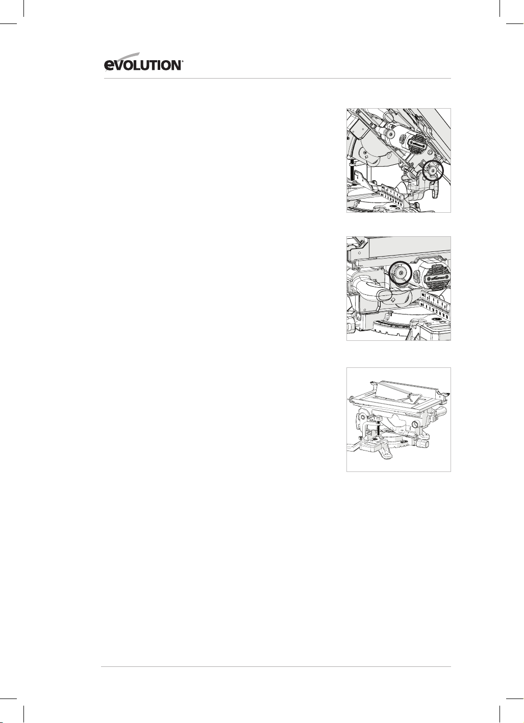
96
www.evolutionpowertools.com
8. Rimozione del materiale incastrato
• Spegnere la troncatrice (OFF) e consentire alla lama di fermarsi del
tutto.
• Se possibile, consentire alla testa da taglio di sollevarsi nella sua
posizione più alta.
• Scollegare la troncatrice dalla fonte di alimentazione.
• Rimuovere con attenzione dall'apparecchio tutto il materiale
incastrato.
PER CONFIGURARE R210MTS-G2 COME SEGA DA BANCO
ATTENZIONE: Non tagliare metallo o materiali metallici quando
l'utensile è configurato come sega da banco.
ATTENZIONE: Effettuare la presente procedura esclusivamente con
l'utensile disconnesso dalla fonte di alimentazione.
• Accertarsi che il banco girevole sia impostato su un angolo di
smusso a 0° e la testa da taglio su un angolo di bisello a 0°.
• Portare la testa da taglio nella sua posizione di abbassamento
massimo. Premere il perno di bloccaggio della testa da taglio nel
proprio alloggiamento. (Fig. 17)
• Ritrarre il perno di blocco motore e ruotare quest'ultimo verso
l'alto. (Fig. 18)
R210MTS-G2 è ora pronta per essere usata come sega da banco.
(Fig. 19)
IL SISTEMA DI BATTUTA COME BATTUTA LONGITUDINALE
Per utilizzare il sistema di battuta come battuta longitudinale,
la piastra frontale deve essere accuratamente allineata con la
lama.
ATTENZIONE: Effettuare la presente procedura
esclusivamente con l'utensile disconnesso dalla fonte di
alimentazione.
Per allineare la battuta longitudinale:
• Impostare lo smusso a 0˚ tramite le scale di misura presenti
sul banco.
• Allineare la battuta tramite le scale di misura sul piano del
banco e bloccarla in sede con le due apposite leve.
PROCEDURE DI BASE CON LA SEGA DA BANCO
ATTENZIONE: Non tagliare metallo o materiali metallici
quando l'utensile è configurato come sega da banco.
ATTENZIONE: Non cimentarsi mai con un taglio a mano libera
mentre si usa il presente utensile. Utilizzare sempre la battuta
longitudinale correttamente regolata per ridurre la possibilità
di inceppo o rinculo della lama.
ATTENZIONE: Il presente utensile non è indicato per
intervenire su tagli o scanalature interrotte.
Avvertenza: Sul lato anteriore sinistro dell'utensile è possibile
collegare, se necessario, un dispositivo di aspirazione delle
polveri di tipo industriale.
Fig. 18
Fig. 17
Fig. 19

97
www.evolutionpowertools.com
IT
1. Gli interruttori On/Off della sega da banco (Fig. 20)
• Premere il pulsante verde (I) per avviare il motore.
• Premere il pulsante rosso (O) per arrestare il motore.
2. Taglio longitudinale
Avvertenza: Verificare che la battuta longitudinale sia
bloccata in posizione e parallela alla lama della sega. Verificare
che la lama guida separatrice sia adeguatamente allineata con
la lama principale.
Nelle operazioni di taglio di materiale dalla sezione ridotta, si
consiglia di usare uno spingipezzo per guidare/accompagnare
il materiale negli ultimi 300 mm del taglio. Lo spingipezzo deve
essere utilizzato d'abitudine nel taglio di pezzi inferiori a tale
dimensione.
Avvertenza: Uno spingipezzo è in dotazione a R210MTS-G2
e dispone di un suo alloggiamento dedicato sul lato anteriore
dell'utensile.
Si raccomanda, quando non utilizzato, di conservare lo
spingipezzo nel suo alloggiamento. (Fig. 21)
Nel caso di tagli di tavole o pannelli di lunghe dimensioni si
consiglia di utilizzare sempre un sistema di sostegno a distanza
o di avvalersi di un aiuto qualificato.
Le mani non devono mai trovarsi sulla linea della lama.
Avvertenza: Lo spingipezzo deve essere sostituito in caso di
danni.
VERIFICA E IMPOSTAZIONE DEGLI ANGOLI DI SMUSSO
ATTENZIONE: Prima di effettuare qualunque regolazione,
accertarsi che l'utensile sia scollegato dalla fonte di
alimentazione.
Avvertenza: Nonostante tutte le impostazioni angolari siano
fissate in fabbrica, potrebbero essere necessarie verifiche e
regolazioni in conseguenza dell'usura dovuta a un normale
utilizzo.
Avvertenza: Per verificare e regolare gli angoli di smusso
l'utensile deve essere in configurazione troncatrice.
ANGOLO DI SMUSSO 0°
In angolo di smusso a 0° la lama deve essere perpendicolare
e a esattamente 90° rispetto al banco girevole. È necessaria
una squadra di precisione (non in dotazione) per verificare un
angolo di smusso a 0°.
Per effettuare la verifica:
• Accertarsi che la testa da taglio sia in posizione verticale,
contro il suo fermo e con l'indicatore di smusso che indica
Fig. 20
Fig. 21

98
www.evolutionpowertools.com
un angolo a 0°.
• Serrare la manopola di blocco dello smusso.
• Abbassare la testa da taglio nella sua posizione di minima
altezza. Bloccare in sede tramite il perno di blocco testa e
sollevare manualmente il coprilama inferiore.
La squadra di precisione può ora essere usata per verificare
l'angolo tra la lama e il banco girevole.
In caso sia necessaria regolazione:
Avvertenza: La testa da taglio dovrà essere inclinata per
guadagnare accesso alla vite di regolazione del fermo di
smusso a 0°.
• Allentare leggermente il controdado della vite di
regolazione del fermo di smusso a 0°. (Fig. 22)
• Utilizzare una chiave a brugola per girare, secondo necessità,
in senso orario o antiorario la vite di fermo smusso.
• Una volta raggiunto l'esatto allineamento tra la
lama e il banco girevole, stringere il controdado.
ANGOLO DI SMUSSO 45°
L'angolo di smusso a 45° può essere verificato in maniera simile
a quella dell'angolo di smusso a 0°. Sarà necessario un set di
squadre di precisione da 45° (non in dotazione).
Per effettuare la verifica:
• Accertarsi che la testa da taglio sia inclinata in posizione a
45°, contro il suo fermo e con l'indicatore di smusso
che indica un angolo a 45°.
• Serrare la manopola di blocco dello smusso.
• Abbassare la testa da taglio nella sua posizione di minima
altezza. Bloccare in sede tramite il perno di blocco testa e
sollevare manualmente il coprilama inferiore.
• Usare il set di squadre di precisione da 45° per verificare
l'angolo tra la lama e il banco girevole.
In caso sia necessaria regolazione:
Avvertenza: La testa da taglio dovrà essere inclinata per
guadagnare accesso alla vite di regolazione del fermo di
smusso a 45°.
• Allentare leggermente il controdado della vite di
regolazione del fermo di smusso a 45°. (Fig. 23)
• Utilizzare una chiave esagonale per girare, come necessario,
in senso orario o antiorario la vite del fermo di smusso.
• Una volta raggiunto l'esatto allineamento tra la lama e il
banco girevole, stringere il controdado.
Fig. 22
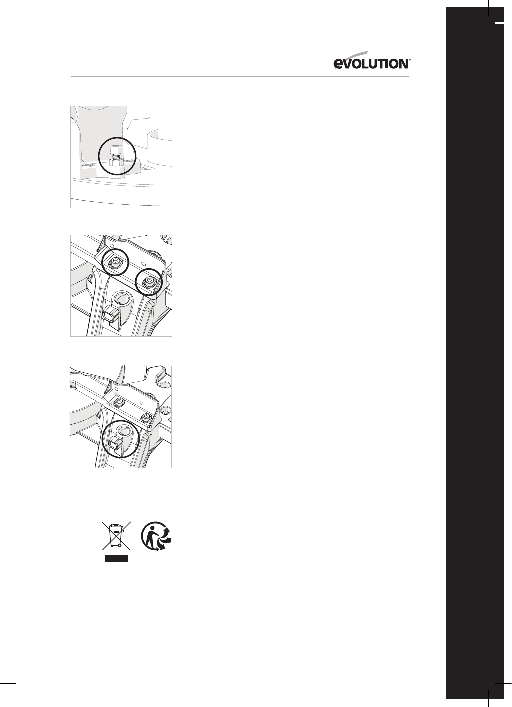
99
www.evolutionpowertools.com
IT
REGOLAZIONE BATTUTA (Fig. 24a & 24b)
La battuta è assicurata alla base dell'utensile da quattro viti
a testa esagonale, due per lato. Tali viti sono collocate in fori
allungati, che consentono alla battuta di essere riposizionata
come necessario.
La battuta deve essere allineata esattamente a 90° con una
lama installata in maniera corretta. Per posizionare con
precisione la battuta sarà necessario un set di squadre di
precisione (non in dotazione).
Per riposizionare la battuta:
• Impostare il banco girevole a un angolo di bisello di 0°.
• Impostare la testa da taglio a un angolo di smusso di 0°.
• Allentare leggermente le quattro viti a testa esagonale della
battuta.
• Abbassare la testa da taglio nella sua posizione di minima
altezza.
• Verificare l'allineamento della battuta con la lama tramite il
set di squadre di precisione.
• Allineare la battuta come necessario e quindi stringere le viti
a testa esagonale.
MANUTENZIONI E REGOLAZIONI
ATTENZIONE: Accertarsi di scollegare l'utensile dalla
fonte di alimentazione prima di eseguire qualunque
operazione di manutenzione o regolazione.
Pulizia
Dopo ogni utilizzo l'utensile deve essere pulito. Rimuovere
segatura, ecc. dalle parti visibili dell'utensile tramite un
aspiratore. Un dispositivo aspiratore può essere inserito
all'attacco di aspirazione posto sul retro dell'apparecchio. In
tal modo dovrebbero essere rimossi anche i detriti depositatisi
all'interno dell'utensile. Non utilizzare mai solventi per pulire le
parti in plastica. Tali prodotti potrebbero arrecare danni. Pulire
esclusivamente con un panno morbido e leggermente umido.
Al fine di allungare la durata di vita dell'utensile, oliare le
parti rotanti con cadenza mensile. Non oliare il motore. Non
utilizzare prodotti corrosivi per la pulizia delle parti in plastica.
ATTENZIONE: L'utensile non deve mai venire a contatto con
l'acqua.
TUTELA AMBIENTALE
I rifiuti di materiale elettrico non devono essere smaltiti
insieme a quelli domestici. Si prega di riciclare laddove siano
presenti adeguate infrastrutture. Verificare con il proprio ente
responsabile locale o con il rivenditore le indicazioni per il
riciclo.
Fig. 23
Fig. 24a
Fig. 24b
100
www.evolutionpowertools.com
DICHIARAZIONE DI CONFORMITÀ CE
Il produttore del prodotto oggetto della presente dichiarazione:
UK: Evolution Power Tools Ltd. Venture One, Longacre Close, Holbrook Industrial Estate, Sheeld, S20 3FR.
FR: Evolution Power Tools SAS. 61 Avenue Lafontaine, 33560, Carbon-Blanc, Bordeaux, Francia.
Il produttore dichiara di seguito che l'utensile, come illustrato nella presente dichiarazione, soddisfa le disposizioni
pertinenti della Direttiva Macchine e delle altre direttive idonee come di seguito descritto.
Il produttore dichiara inoltre che l'utensile, così come illustrato nella presente dichiarazione, laddove applicabile, soddisfa
le disposizioni pertinenti della normativa relativa ai requisiti essenziali di sicurezza e tutela della salute (EHSRs).
Le direttive oggetto della presente dichiarazione sono quelle di seguito riportate:
2006/42/CE. Direttiva Macchine.
2014/30/UE. Direttiva Compatibilità Elettromagnetica
La Direttiva sulla restrizione all’uso di sostanze
pericolose nelle apparecchiature elettriche ed elettroniche (RoHS)
2012/19/UE. La Direttiva sui Riuti da Apparecchiature Elettriche ed Elettroniche (RAEE).
Ed è in conformità con i requisiti applicabili dei seguenti documenti:
EN 61029-1:2009+A11• EN 61029-2-11:2012+A11• EN 55014-1:2017+A11:2020 •
EN IEC 55014-1:2021 • EN IEC 55014-2:2021 • EN IEC 61000-3-2:2019+A1 •
EN IEC 61000-3-11:2019
EC type approval to 2006/42/EC Article 12 Section 3b Machinery
TÜV Rheinland LGA Products GmbH - Tillystraße 2 - 90431 Nürnberg
No.: 0197 Reg. No.: BM 50592380 0001
Dettagli prodotto
Descrizione: R210MTS G2 SEGA DA BANCO/TRONCATRICE MULTI-MATERIALE DA 210 mm
Evolution
modello N: 116-0001, 116-0002, 116-0003, 116-0004
Marca: EVOLUTION
Tensione: 220-240 V~ 50 Hz
Ingresso: 1500 W
La documentazione tecnica a suragio della compatibilità del prodotto con i requisiti della direttiva è stata redatta e messa
a disposizione per la consultazione da parte delle autorità preposte pertinenti. Essa dimostra che le nostre schede tecniche
contengono i documenti sopra elencati e che soddisfano i criteri corretti per il prodotto così come in precedenza illustrato.
Nome e indirizzo del titolare della documentazione tecnica.
Firmato: Stampa: Barry Bloomer
Direttore della catena di fornitura e
approvvigionamento
Data: 08/02/2022
UK: Evolution Power Tools Ltd. Venture One, Longacre Close, Holbrook Industrial Estate, Sheeld, S20 3FR.
FR: Evolution Power Tools SAS. 61 Avenue Lafontaine, 33560, Carbon-Blanc, Bordeaux, Francia.
2011/65/UE. e
2015/863/UE.

101
www.evolutionpowertools.com
IT

102
www.evolutionpowertools.com
WAŻNE
Należy uważnie iwcałości zapoznać się ztreścią
niniejszej instrukcji obsługi oraz bezpieczeństwa.
Ze względów bezpieczeństwa w przypadku
wątpliwości co do któregokolwiek aspektu
dotyczącego korzystania z tego sprzętu należy
skontaktować się z odpowiednią infolinią obsługi
technicznej, której numer podany jest na stronie
internetowej firmy Evolution Power Tools.
Nasza ogólnoświatowa organizacja oferuje
dostęp do kilku infolinii. Pomocą techniczną
służą również dystrybutorzy.
Strona internetowa:
www.evolutionpowertools.com
E-MAIL
UK:customer[email protected]
USA: evolutioninfo@evolutionpowertools.com
GWARANCJA
Gratulujemy zakupu narzędzia marki Evolution
Power Tools. Produkt należy zarejestrować na
stronie internetowej zgodnie z informacjami
zawartymi w dołączonej do urządzenia
ulotce. Umożliwi to zatwierdzenie okresu
gwarancyjnego urządzenia za pośrednictwem
strony internetowej Evolution poprzez podanie
danych osobowych, co w razie potrzeby zapewni
szybki dostęp do usług serwisowych.
Serdecznie dziękujemy za wybranie produktu
marki Evolution Power Tools.
Firma Evolution Power Tools zastrzega sobie
prawo do wprowadzania ulepszeń oraz zmian
wkonstrukcji produktu bez uprzedniego
powiadomienia.
Proszę zapoznać się zulotką rejestracyjną i/
lub opakowaniem wcelu uzyskania informacji
ozasadach iwarunkach gwarancji.

103
www.evolutionpowertools.com
PL
SPECYFIKACJE
URZĄDZENIE GB/EU
Silnik (220-240 V~ 50 Hz) 1500 W
Prędkość bez obciążenia 3800 min
-1
Waga 13 kg
MOŻLIWOŚCI CIĘCIA GB/EU
Płyta z mięk kiej stali – maksymalna grubość 3 mm
Płyta z mięk kiej stali – maksymalna twardość 210 HB
MAKSYMALNA MOŻLIWOŚĆ CIĘCIA (ALUMINIUM, DREWNO I PCW)
KONFIGURACJA UKOŚNICY
UCHYŁ TARCZY UKOS GB/EU
0° 0° 55 x 120 mm
45° 0° 35 x 120 mm
0° 45° w lewo 55 x 65 mm
0° 45° w prawo 55 x 55 mm
45° 45° w lewo 35 x 30 mm
45° 45° w prawo 35 x 70 mm
MAKSYMALNA MOŻLIWOŚĆ CIĘCIA – KONFIGURACJA PILARKI STOŁOWEJ
MOŻLIWOŚCI CIĘCIA UK / UE
Drewno – maksymalna grubość 40 mm
WYMIARY TARCZY UK / UE
Średnica Tarcza diamentowa
Średnica otworu 25.4 mm
Liczba zębów 20
Grubość 1.7 mm
DANE DOT. HAŁASU I WIBRACJI
Poziom ciśnienia akustycznego L
P
A 103 dB(A); K = 3 dB(A)
Poziom mocy akustycznej L
W
A 116 dB(A); K = 3 dB(A)
104
www.evolutionpowertools.com
Podane wartości emisji hałasu zostały zmierzone
zgodnie ze standardowymi metodami testowymi
(EN 61029-1, EN 61029-2-11) i mogą posłużyć do
porównywania różnych narzędzi.
OSTRZEŻENIE: Emisja hałasu podczas
rzeczywistego użytkowania elektronarzędzia
może różnić się od podanej wartości całkowitej
w zależności od sposobu używania narzędzia
oraz w szczególności od rodzaju obrabianego
przedmiotu.
Konieczne jest zidentyfikowanie środków
bezpieczeństwa mających na celu ochronę
operatora, które opierają się na ocenie narażenia
w rzeczywistych warunkach użytkowania (z
uwzględnieniem wszystkich etapów cyklu
operacyjnego, takich jak czas kiedy narzędzie jest
wyłączone i kiedy pracuje na biegu jałowym, w
dodatku do czasu aktywacji)
OZNACZENIA I SYMBOLE
OSTRZEŻENIE: Nie wolno korzystać z narzędzia,
jeśli oznaczenia ostrzegawcze i/lub informacyjne
są uszkodzone lub zostały usunięte. Należy
skontaktować się z firmą Evolution Power Tools w
celu uzyskania nowych etykiet.
Uwaga: Wszystkie lub niektóre z następujących
symboli mogą znajdować się w instrukcji lub na
produkcie.
Symbol Opis
V
Wolty
A
Ampery
Hz
Herce
Min
-1
Prędkość
~
Prąd zmienny
n
o
Prędkość bez obciążenia
Należy założyć okulary ochronne
Należy stosować środki
ochrony słuchu
Nie dotykać
Należy stosować ochronę przed
pyłem
Należy zapoznać się z instrukcją
Certyfikat CE
Certyfikat UKCA
Ostrzeżenie
Zużyty sprzęt elektryczny
i elektroniczny
Podwójna izolacja
Triman – zbieranie
odpadów irecykling

105
www.evolutionpowertools.com
PL
PRZEWIDZIANE ZASTOSOWANIE
ELEKTRONARZĘDZIA
OSTRZEŻENIE: Niniejszy produkt to ręczna
wielofunkcyjna ukośnica zaprojektowana do
eksploatacji z wykorzystaniem specjalnych
tarcz marki Evolution. Należy używać
wyłącznie akcesoriów zaprojektowanych do
stosowania z tym narzędziem lub akcesoriów
zalecanych przez Evolution Power Tools Ltd.
Po założeniu odpowiedniej tarczy urządzenie
to nadaje się do cięcia:
stali miękkiej
aluminium
drewna
plastiku
ZABRONIONE ZASTOSOWANIE
ELEKTRONARZĘDZIA
OSTRZEŻENIE: Niniejszej wielofunkcyjnej
ukośnicy ręcznej należy używać wyłącznie
zgodnie zprzeznaczeniem. Nie wolno
wprowadzać w urządzeniu żadnych
modyfikacji ani stosować go do zasilania
jakichkolwiek urządzeń lub akcesoriów innych
niż określone w niniejszej instrukcji.
OSTRZEŻENIE: Urządzenie nie jest
przeznaczone do użytkowania przez
dzieci i osoby o ograniczonej sprawności
fizycznej, sensorycznej lub umysłowej, lub
nieposiadające odpowiedniego doświadczenia
i wiedzy, chyba że będą one nadzorowane
lub zostaną poinstruowane na temat
bezpiecznego korzystania z urządzenia przez
osobę odpowiedzialną za ich bezpieczeństwo
i kompetentną w zakresie bezpiecznego
korzystania z urządzenia.
Dzieci wymagają stałego nadzoru, aby nie
miały żadnego dostępu do sprzętu. Nie wolno
pozwalać im na zabawę urządzeniem.
BEZPIECZEŃSTWO ELEKTRYCZNE
Urządzenie jest wyposażone w odpowiednio
profilowaną wtyczkę i kabel zasilający
dostosowany do danego rynku. W przypadku
uszkodzenia kabla zasilającego należy go
wymienić na specjalny kabel lub zespół
dostępny u producenta lub autoryzowanego
dystrybutora.
UŻYTKOWANIE NA ZEWNĄTRZ
OSTRZEŻENIE: Jeśli urządzenie będzie
eksploatowane na wolnym powietrzu, ze
względów bezpieczeństwa nie należy używać
go w miejscach zawilgoconych ani narażać na
działanie deszczu.
Nie należy umieszczać narzędzia na wilgotnym
podłożu.
W miarę możliwości należy ustawić je na
czystym i suchym blacie roboczym.
W celu zapewnienia dodatkowej ochrony
należy zastosować wyłącznik różnicowo-
prądowy (RCD), który przerwie dopływ
zasilania, jeśli prąd różnicowy przekroczy
30mA przez okres 30ms. Należy zawsze
sprawdzić działanie wyłącznika różnicowo-
prądowego (RCD) przed przystąpieniem do
korzystania z urządzenia.
W przypadku konieczności zastosowania
przedłużacza należy upewnić się, że nadaje się
on do użytku na zewnątrz i jest odpowiednio
oznaczony. Podczas korzystania z przedłużacza
należy przestrzegać instrukcji producenta.
OGÓLNE INSTRUKCJE BEZPIECZEŃSTWA
ELEKTRONARZĘDZI
• Należy stosować się do wszystkich tych
instrukcji przed i podczas pracy z piłą.
• Przechowywać te instrukcje w bezpiecznym
miejscu.
• Unikać zetknięcia ciała z uziemionymi
komponentami.
• Gdy sprzęt nie jest używany, należy go
przechowywać w suchym, zamkniętym
miejscu poza zasięgiem dzieci.
• Ostre i czyste narzędzia sprawią, że praca
będzie łatwiejsza i bezpieczniejsza. Należy
regularnie sprawdzać przewód zasilający
i przy pierwszych oznakach uszkodzenia
zlecić jego wymianę autoryzowanemu
specjaliście.
• Należy regularnie sprawdzać przedłużacze i
wymienić je w przypadku uszkodzenia.
• Podczas pracy na zewnątrz należy używać
tylko przedłużaczy zatwierdzonych
do użytku na zewnątrz i odpowiednio
oznaczonych.
• Należy skoncentrować się na wykonywanej
czynności. Należy przyjąć rozsądne
podejście do swojej pracy. Nigdy nie
obsługiwać narzędzia, gdy operator jest
zmęczony.
• Nigdy nie używać narzędzia z
przełącznikiem, którego nie można włączać
i wyłączać.
• Uwaga! Korzystanie z wyposażonych we
wtyczkę narzędzi i akcesoriów innych niż
przeznaczone do danej czynności może
narazić operatora na ryzyko obrażeń.
• Maszyna jest wyposażona w wyłącznik
bezpieczeństwa, aby zapobiec jej
ponownemu przypadkowemu włączeniu
po awarii zasilania (w trybie piły stołowej).
• Nigdy nie używać piły do cięcia okrągłych
fragmentów drewna.

106
www.evolutionpowertools.com
• Należy sprawdzać przewód zasilający.
Nigdy nie używać przewodu wadliwego lub
uszkodzonego.
• Nie używać przewodu do wyciągania
wtyczki z gniazdka elektrycznego. Chronić
przewód przed ciepłem, olejami i ostrymi
krawędziami.
• Zalecamy noszenie obuwia
antypoślizgowego podczas pracy na
zewnątrz.
• Długie włosy należy upiąć w siatce na włosy.
• Unikać nieprawidłowych pozycji roboczych.
• Nieuporządkowany obszar roboczy może
prowadzić do wypadków.
• Nie pozwalać innym osobom, w
szczególności dzieciom, dotykać narzędzia
lub przewodu zasilającego. Należy dbać o
to, aby inne osoby zachowały bezpieczną
odległość od miejsca pracy.
• Rozdzielacz jest ważnym urządzeniem
zabezpieczającym. Nie tylko prowadzi
obrabiany przedmiot, ale także zapobiega
zamykaniu się szczeliny za tarczą, co
pozwala uniknąć odbicia. Należy zwrócić
uwagę na grubość rozdzielacza: nigdy nie
powinien być cieńszy niż korpus tarczy lub
grubszy niż szerokość szczeliny.
• Górna osłona tarczy piły musi zostać
opuszczona na obrabiany przedmiot przed
każdą czynnością cięcia.
• Należy używać popychacza podczas
cięcia wąskich przedmiotów o szerokości
mniejszej niż 120 mm lub dociskacza
podczas cięcia wąskich przedmiotów o
szerokości mniejszej niż 30 mm.
WAŻNE: Nigdy nie używać tej piły do
wykonywania cięć wgłębnych.
• Należy zawsze stać z boku tarczy podczas
pracy z ukośnicą.
• Upewnić się, że odcięte fragmenty nie
zaczepiają się o tarczę, aby zapobiec ich
gwałtownemu odbiciu od urządzenia.
• Jeśli szczelina do cięcia jest zużyta,
wymienić podkładkę stołu.
• Aby zapobiec obrażeniom spowodowanym
latającymi trocinami i wiórami, należy
używać piły tylko z odpowiednim systemem
usuwania pyłu lub standardowym
odkurzaczem przemysłowym.
• Zawsze wyciągać wtyczkę z gniazdka
elektrycznego przed regulacją lub
serwisowaniem urządzenia.
• Należy przekazać te instrukcje
bezpieczeństwa wszystkim osobom, które
obsługują urządzenie.
• Nie używać tej pilarki do cięcia włókna
drzewnego.
• Uwaga! Obracająca się tarcza może
spowodować obrażenia rąk i palców.
• Przed użyciem urządzenia po raz pierwszy
należy sprawdzić, czy napięcie podane na
tabliczce znamionowej jest takie samo jak
napięcie sieciowe.
• Jeśli konieczne jest użycie przedłużacza,
należy upewnić się, że przekrój przewodu
jest wystarczająco duży dla poziomu energii
pobieranej przez urządzenie. Minimalny
przekrój: 1,0 mm2.
• W razie korzystania z bębna kablowego cały
przewód musi zostać rozwinięty z bębna.
• Nigdy nie przenosić piły trzymając za
przewód.
• Nie zostawiać piły na deszczu i nigdy
nie używać jej w miejscu wilgotnym lub
mokrym.
• Zapewnić należyte oświetlenie.
• Nigdy nie obsługiwać piły w pobliżu
palnych cieczy lub gazów.
• Zakładać odpowiednią odzież roboczą.
Luźna odzież lub biżuteria może zostać
uwięziona w obracającej się tarczy.
• Operatorzy muszą mieć ukończone 18 lat.
Stażyści w wieku co najmniej 16 lat mogą
korzystać z maszyny tylko pod nadzorem.
• Trzymać dzieci z dala od urządzenia, gdy
jest ono podłączone do zasilania.
WAŻNE:
• Należy sprawdzać przewód zasilający.
Nigdy nie używać przewodu wadliwego lub
uszkodzonego.
• Utrzymywać miejsce pracy w czystości, bez
żadnych fragmentów drewna i wszelkich
niepotrzebnych przedmiotów.
• Nie rozpraszać uwagi osób obsługujących
urządzenie.
• Zwrócić uwagę na kierunek obrotu silnika
i tarczy.
• Po wyłączeniu silnika nigdy nie spowalniać
tarczy, naciskając na jej bok.
• Stosować tylko tarcze, które są dobrze
naostrzone i nie mają pęknięć ani
odkształceń.
• Maszyna może być obsługiwana wyłącznie
za pomocą narzędzi zgodnych z normą
• EN 847-1.
• Wadliwe tarcze należy natychmiast
wymienić.
• Nigdy nie używać tarcz niezgodnych z
danymi określonymi w niniejszej instrukcji.
• Upewnić się, że strzałka na tarczy
jest zgodna ze strzałką oznaczoną na
urządzeniu.
• Upewnić się, że tarcza nie dotyka stołu
obrotowego w żadnym ustawieniu. W
tym celu należy wyjąć wtyczkę zasilania
i przechylić ręcznie tarczę pod kątem

107
www.evolutionpowertools.com
PL
45° i 90°. W razie potrzeby ponownie
wyregulować głowicę piły.
• Konieczne jest upewnienie się, że wszystkie
urządzenia używane do przykrywania
tarczy są w dobrym stanie.
• Nigdy nie blokować pokrywy ochronnej z
zawiasami w pozycji otwartej.
ZALECENIA ZDROWOTNE
OSTRZEŻENIE: Podczas korzystania z urządzenia
mogą wytworzyć się cząsteczki pyłu. W niektórych
przypadkach, w zależności od wykorzystywanych
materiałów, pył może być szczególnie szkodliwy.
W przypadku podejrzenia, że farba pokrywająca
powierzchnię ciętego materiału zawiera ołów,
należy zasięgnąć porady specjalisty. Farby
na bazie ołowiu mogą zostać usunięte tylko
przez profesjonalistę i nie należy podejmować
samodzielnych prób ich usuwania. Po osadzeniu
się pyłu na powierzchniach przeniesienie go
dłońmi do jamy ustnej może doprowadzić do
spożycia ołowiu.
Nawet niewielka ilość ołowiu może spowodować
nieodwracalne uszkodzenie mózgu iukładu
nerwowego. Szczególnie narażone są małe i
nienarodzone dzieci. Zaleca się ocenę ryzyka
związanego z obróbką danego materiału i
ograniczenie
narażenia na szkodliwe czynniki. Niektóre
materiały mogą produkować pyły szkodliwe dla
zdrowia. Podczas korzystania z urządzenia
zalecamy stosowanie zatwierdzonych masek
przeciwpyłowych z wymiennymi filtrami.
Należy zawsze:
• pracować w dobrze wentylowanym miejscu;
• korzystać z zatwierdzonych środków
bezpieczeństwa, takich jak maski
przeciwpyłowe, zaprojektowane specjalnie, po
to aby filtrować mikroskopijne cząsteczki.
OSTRZEŻENIE: Podczas korzystania z
dowolnego elektronarzędzia ciała obce mogą
zostać wyrzucone w kierunku oczu operatora,
co może skutkować poważnym urazem narządu
wzroku. Przed przystąpieniem do pracy z
elektronarzędziem należy założyć okulary lub
gogle ochronne z osłoną boczną. W miarę
potrzeby należy zastosować całkowitą osłonę
twarzy.
DODATKOWE INSTRUKCJE BEZPIECZEŃSTWA
UKOŚNICE
Poniższe szczegółowe instrukcje bezpieczeństwa
dotyczące korzystania zukośnic oparte są na
wymogach normy
EN 61029-2-11
ZASADY BEZPIECZEŃSTWA: TARCZA
OSTRZEŻENIE: Obracające się tarcze tnące są
niezwykle niebezpieczne i mogą spowodować
poważne obrażenia ciała oraz amputacje. Należy
zawsze trzymać palce i dłonie w odległości
przynajmniej 150 mm od tarczy. Nie wolno
podejmować próby wyciągnięcia ciętego
materiału dopóki głowica tnąca nie zostanie
uniesiona, osłona całkowicie zamknięta oraz
dopóki tarcza nie przestanie się obracać.
Należy używać wyłącznie tarcz zalecanych przez
producenta i zgodnych z opisem w niniejszej
instrukcji oraz z wymogami normy
EN 847-1.
Nie wolno używać tarcz, które są zniszczone lub
odkształcone, ponieważ może to spowodować
uszkodzenie osłony i poważne obrażenia ciała u
operatora lub osób postronnych.
Nie należy używać tarcz wyprodukowanych ze
stali szybkotnącej (HSS).
W przypadku uszkodzenia lub zużycia podkładki
stołowej, należy ją wymienić na identyczną
podkładkę dostępną u producenta, zgodnie z
instrukcjami zawartymi w niniejszej instrukcji
obsługi.
ŚRODKI OCHRONY INDYWIDUALNEJ
Należy zakładać ochraniacze na uszy w celu
zmniejszenia ryzyka utraty słuchu.
Należy stosować środki ochrony oczu w celu
zapobiegania ryzyka utraty wzroku w wyniku
wyrzucenia odłamków materiału.
Zalecana jest również ochrona układu
oddechowego, ponieważ niektóre rodzaje drewna
imateriały drewniane, zwłaszcza MDF (płyta
pilśniowa średniej gęstości zwłókien drzewnych)
mogą produkować pyły szkodliwe dla zdrowia.
Podczas korzystania znarzędzia zalecamy
stosowanie zatwierdzonych masek
przeciwpyłowych zwymiennymi filtrami oraz
systemu odsysania pyłu.
Przed obsługą tarcz lub szorstkich materiałów
należy założyć rękawice ochronne. W miarę
możliwości zalecane jest stosowanie pokrowców
na tarcze. Zakładanie rękawic do obsługi ukośnicy
nie jest zalecane.
BEZPIECZNA OBSŁUGA
Należy zawsze upewnić się, że wybrana tarcza jest
odpowiednia do cięcia wybranego materiału.
Nie wolno używać tej ukośnicy do cięcia
materiałów innych niż wymienione w niniejszej
instrukcji.

108
www.evolutionpowertools.com
Podczas transportu ukośnicy należy upewnić się,
że głowica tnąca jest zablokowana pod kątem
90 stopni w pozycji opuszczonej (w przypadku
ukośnicy przesuwnej należy zablokować szyny
suwakowe). Należy podnieść maszynę za
krawędzie zewnętrzne podstawy obiema rękami
(w przypadku ukośnicy przesuwnej chwycić za
odpowiednie uchwyty). Pod żadnym pozorem
nie podnosić ani nie transportować maszyny
chwytając za odchylaną osłonę lub jakąkolwiek
część mechanizmu roboczego.
Przed każdym użyciem należy sprawdzić działanie
odchylającej się osłony i jej mechanizmu,
upewniając się, że nie są uszkodzone i że
wszystkie elementy ruchome działają sprawnie i
prawidłowo.
Należy zadbać o to, aby stół roboczy i miejsce
pracy były wolne od wszelkich odłamków, w tym
pyłu, wiórów i odciętych kawałków.
Należy zawsze sprawdzić i upewnić się, że
prędkość oznaczona na tarczy jest przynajmniej
równa prędkości na biegu jałowym wskazanej na
ukośnicy.
Pod żadnym pozorem nie należy używać tarczy z
oznaczeniem prędkości niższym niż prędkość na
biegu jałowym wskazana na ukośnicy.
Jeśli konieczne jest skorzystanie z przekładki
lub pierścieni redukcyjnych, muszą być one
odpowiednie do danego zastosowania i zgodne z
zaleceniami producenta.
Tarcza tnąca może być wymieniana tylko zgodnie
z instrukcjami zamieszczonymi w niniejszej
instrukcji obsługi.
Nie wolno podejmować próby wyciągnięcia
odciętych kawałków lub innych części przedmiotu
obróbki, dopóki głowica tnąca nie zostanie
uniesiona, osłona całkowicie zamknięta oraz
dopóki tarcza nie przestanie się obracać.
PRAWIDŁOWE I BEZPIECZNE WYKONYWANIE
CIĘĆ
W miarę możliwości należy zawsze zabezpieczyć
narzędzie obróbki na stole ukośnicy przy pomocy
zacisku.
Przed przystąpieniem do każdego cięcia należy
upewnić się, że ukośnica jest zamontowana w
stabilnej pozycji.
W razie potrzeby ukośnica może zostać
zamontowana
na drewnianej podstawie lub stole warsztatowym
albo przymocowana do stanowiska dla ukośnicy,
jak opisano w instrukcji obsługi.
Długie przedmioty obróbki należy zamocować na
załączonych wspornikach lub na odpowiednich
podporach dodatkowych.
OSTRZEŻENIE: W przypadku braku jakichkolwiek
części urządzenia nie należy go uruchamiać
aż do momentu uzupełnienia brakujących
komponentów. Nieprzestrzeganie tego zalecenia
może spowodować poważne obrażenia ciała.
DODATKOWE INSTRUKCJE BEZPIECZEŃSTWA
PRZENOSZENIE UKOŚNICY
Zalecenia bezpieczeństwa
• Mimo kompaktowych rozmiarów ukośnica
to ciężkie narzędzie. Aby zmniejszyć poziom
ryzyka urazów pleców, należy zorganizować
pomoc do podniesienia urządzenia.
• Aby obniżyć poziom ryzyka urazów pleców,
podczas podnoszenia należy trzymać
urządzenie blisko ciała. Należy ugiąć kolana
ipodnosić ciężar za pomocą pracy nóg, nie
pleców. Podnosić za uchwyty umieszczone po
obu stronach podstawy.
• Nie wolno przenosić urządzenia, chwytając
za przewód zasilania. Trzymanie za przewód
zasilający podczas przenoszenia może
spowodować uszkodzenie izolacji lub złączy,
powodując porażenie prądem lub pożar.
• Przed przystąpieniem do przeniesienia
ukośnicy należy dokręcić śruby
blokujące ustawienie uchyłu oraz skosu,
aby zabezpieczyć je przed nagłymi
inieoczekiwanymi ruchami.
• Należy zablokować głowicę tnącą w
najniższej pozycji. Należy upewnić się,
że bolec blokujący głowicy tnącej jest
odpowiednio umiejscowiony w swoim
gnieździe.
OSTRZEŻENIE: Nie chwytać za osłonę
tarczy podczas podnoszenia narzędzia. Przed
przystąpieniem do przenoszenia urządzenia
należy wyjąć kabel zasilania z gniazdka.
• Należy zablokować głowicę tnącą w pozycji
dolnej za pomocą bolca blokującego.
• Należy poluzować śrubę blokującą ustawienia
ukosu. Należy przekręcić stół aż do jednego z
ustawień krańcowych.
• Należy zablokować stół w wybranej pozycji za
pomocą śruby blokującej.
• Przenosząc maszynę, należy chwytać za otwory
do chwytania umieszczone po obu stronach
podstawy.
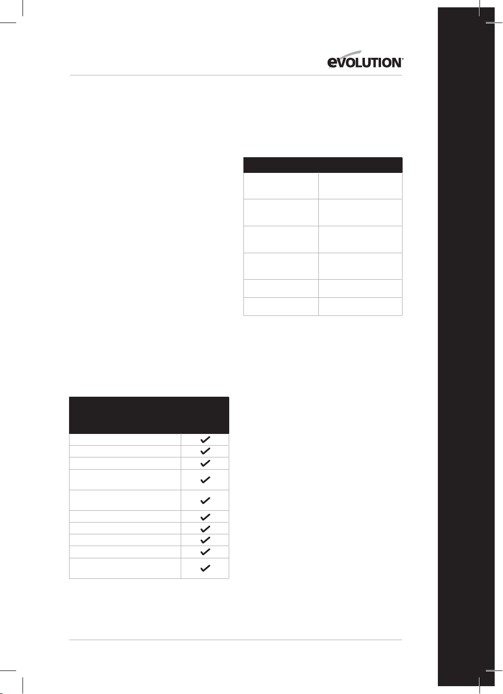
109
www.evolutionpowertools.com
PL
Należy umieścić ukośnicę na bezpiecznej i
stabilnej powierzchni roboczej i dokładnie
obejrzeć urządzenie.
Przed uruchomieniem urządzenia należy
sprawdzić w szczególności działanie wszystkich
zabezpieczeń.
PRZYGOTOWANIE DO PRACY –
ROZPAKOWYWANIE
Uwaga: Opakowanie zawiera ostre przedmioty.
Należy zachować ostrożność podczas
rozpakowywania. Urządzenie wraz z załączonymi
akcesoriami należy wyjąć z opakowania. Należy
dokładnie sprawdzić, czy urządzenie jest w
dobrym stanie i potwierdzić obecność wszystkich
akcesoriów wymienionych w instrukcji obsługi.
Należy również upewnić się, czy w żadnym
z akcesoriów nie brakuje komponentów. W
przypadku braku jakiegokolwiek komponentu
należy zwrócić urządzenie do dystrybutora w
oryginalnym opakowaniu wraz ze wszystkimi
akcesoriami. Nie wyrzucać opakowania.
Opakowanie należy zachować na czas trwania
okresu gwarancyjnego. Opakowanie należy
zutylizować w sposób przyjazny dla środowiska.
Jeśli to możliwe, należy poddać je recyklingowi.
Nie należy pozwalać dzieciom na zabawę
torebkami foliowymi ze względu na ryzyko
uduszenia.
ELEMENTY WYPOSAŻENIA
Opis
116-0001,
116-0002,
116-0003,
116-0004
Instrukcja obsługi
Zacisk przytrzymujący
Popychacz
Klucz maszynowy
(do zmiany tarczy)
Klucz imbusowy z podwójną
końcówką 6-5 mm
Tarcza uniwersalna
Ogranicznik równoległy
Worek na pył
Osłona pilarki stołowej
Elementy przedłużające
podstawy x 2
DODATKOWE AKCESORIA
Poza podstawowymi elementami załączonymi do
niniejszego urządzenia, następujące akcesoria są
również dostępne na stronie
www.evolutionpowertools.com lub u
lokalnego dystrybutora.
Opis Nr części
Uniwersalna tarcza
RAGE TCT
RAGEBLADE210MULTI
Uniwersalna tarcza
do drewna 210 mm
GW210TCT-30
Tarcza do drewna
cienkiego 210 mm
FW210TCT-40
Tarcza diamentowa
210 mm
D210CON
Stojak do ukośnicy 005-0001
Stojak do ukośnicy + 005-0005

110
www.evolutionpowertools.com
OPIS URZĄDZENIA R210MTS-G2
1
3
8
1. UCHWYT DO CIĘCIA
2. STÓŁ OBROTOWY
3. ODCHYLANA DOLNA OSŁONA TARCZY
4. UCHWYT BLOKADY KĄTA SKOSU
5. SKALA REGULACJI KĄTA UKOSU
6. DŻWIGNIA ZWALNIAJĄCA GŁOWICY
TNĄCEJ
7. BOLEC BLOKADY GŁOWICY TNĄCEJ
8. MIEJSCE NA POPYCHACZ
9. PRZEŁĄCZNIK ON/OFF PILARKI
STOŁOWEJ
10. PRZEŁĄCZNIK ON/OFF UKOŚNICY
2
9
10
4
6
5
7

111
www.evolutionpowertools.com
PL
OPIS URZĄDZENIA R210MTS-G2
1. STÓŁ
2. OSŁONA PILARKI STOŁOWEJ
3. OGRANICZNIK RÓWNOLEGŁY
4. POPYCHACZ
5. BOLEC TRYBU PILARKI STOŁOWEJ/
UKOŚNICY
6. DŹWIGNIA BLOKADY UCHYŁU
7. TYLNA LISTWA STABILIZUJĄCA
8. PODPORY ELEMENTU OBRABIANEGO (X 2)
9. MIEJSCE NA NARZĘDZIA
10. DŹWIGNIE BLOKADY OGRANICZNIKA
RÓWNOLEGŁEGO
11. SKALA BLATU STOŁU
2
4
3
1
7
8
9
5
6
10
10
11
11

112
www.evolutionpowertools.com
PRZYGOTOWANIE DO PRACY
OSTRZEŻENIE: PRZED ZMIANĄ USTAWIEŃ ZAWSZE NALEŻY
ODŁĄCZYĆ URZĄDZENIE OD ŹRÓDŁA ZASILANIA.
MONTAŻ URZĄDZENIA R210MTS-G2 NA STAŁE
PILARKA STOŁOWA/UKOŚNICA (Rys. 1)
OSTRZEŻENIE: Aby zredukować ryzyko poniesienia obrażeń
w związku z nieprzewidzianym ruchem urządzenia, należy
umieścić je w odpowiedniej pozycji na stole warsztatowym lub
innym zalecanym zestawie nóg. W podstawie pilarki znajdują
się cztery otwory montażowe. Jeśli urządzenie ma być używane
tylko w jednym miejscu, należy przymocować je na stałe do stołu
warsztatowego lub zestawu nóg, wykorzystując odpowiednie zaciski
z podkładkami i nakrętkami.
1. Dokręcić blokadę ukośnicy i uchyłu tarczy.
2. Ustawić piłę tak, aby inne osoby nie mogły za nią stać. Wyrzucane
odpady mogą spowodować obrażenia.
3. Ukośnicę należy umieścić na sztywnej, równej powierzchni
w miejscu, w którym jest wystarczająco przestrzeni do obsługi i
odpowiedniego podparcia przedmiotu obróbki.
4. Podeprzeć ukośnicę w taki sposób, aby stół obrotowy był
wyrównany, a samo urządzenie się nie kołysało.
5. Ukośnicę należy przykręcić lub przymocować zaciskami do
stanowiska.
TYLNY DRĄŻEK STABILIZUJĄCY
Przedłużyć drążek do tylnej części urządzenia (Rys. 2)
OSŁONA PILARKI STOŁOWEJ
Montaż osłony pilarki stołowej:
• Poluzować 2 śruby sześciokątne kluczem imbusowym
• Zamontować zespół osłony piły stołowej (Rys. 3)
• Dokręcić 2 śruby sześciokątne
MONTAŻ/DEMONTAŻ TARCZY
OSTRZEŻENIE: Należy używać jedynie oryginalnych tarcz Evolution
przeznaczonych do stosowania z tym narzędziem. Należy upewnić
się, że maksymalna prędkość tarczy jest zgodna z tą wskazaną dla
urządzenia. Przed rozpoczęciem tych czynności należy odłączyć
urządzenie od źródła zasilania.
Uwaga: Zaleca się, aby przed montażem lub wymianą tarczy
operator założył rękawice ochronne.
Wymiana tarczy:
• Wyjąć bolec (Rys. 4), aby zwolnić silnik.
• Delikatnie nacisnąć uchwyt głowicy tnącej.
• Wyciągnąć bolec blokujący głowicę tak, aby głowica mogła
unieść się do górnej pozycji. (Rys. 5)
• Za pomocą klucza maszynowego (w zestawie) przytrzymać
zewnętrzny kołnierz tarczy.
• Odkręcić śrubę trzpienia za pomocą klucza imbusowego (w
zestawie). (Rys. 6)
Uwaga: Śruba trzpienia ma gwint lewoskrętny. Obrócić zgodnie
z ruchem wskazówek zegara, aby odkręcić, i przeciwnie do ruchu
wskazówek zegara, aby dokręcić.
Rys. 1
1) Zacisk sześciokątny
2) Podkładka sprężysta
3) Płaska podkładka
4) Podstawa ukośnicy
5) Stół roboczy
6) Płaska podkładka
7) Podkładka
sprężysta
8) Nakrętka
sześciokątna
9) Nakrętka blokująca
(1)
(2)
(3)
(4)
(5)
(6)
(7)
(8)
(9)
Rys. 2
Rys. 4
Rys. 3

113
www.evolutionpowertools.com
PL
• Zdemontować śrubę trzpienia i zewnętrzny kołnierz tarczy.
• Schować dolną osłonę tarczy, naciskając dźwignię zwalniającą
głowicy tnącej i obrócić dolną osłonę do góry, odsłaniając tarczę.
• Wyjąć tarczę, wysuwając ją na zewnątrz tak, aby zsunęła się z
końca trzpienia, a następnie w dół i do przodu, w kierunku od
urządzenia. (Rys. 7)
Klin
Klin to bardzo ważna część urządzenia, która została fabrycznie
zamontowana na osłonie górnej tarczy. Klin przeciwdziała zacinaniu
się przedmiotu obróbki, gdy przechodzi on przez tarczę. Należy
dokonywać regularnego przeglądu klina i wymienić go w przypadku
zużycia lub uszkodzenia.
Klin należy wyregulować tak, aby odstęp między końcówkami
zębów tarczy i krawędzią klina wynosił około 3-5 mm. (Rys. 8)
Aby wyregulować klin, należy delikatnie poluzować dwie śruby
mocujące (Rys. 9) za pomocą klucza imbusowego. Po odpowiednim
wyregulowaniu dokręcić śruby mocujące.
Uwaga: Należy używać wyłącznie oryginalnego zespołu górnej
osłony tarczy Evolution przeznaczonego do tego urządzenia.
Korzystanie z części innych niż oryginalne może być niebezpieczne.
W razie wątpliwości należy skontaktować się z infolinią.
KONFIGURACJA URZĄDZENIA R210MTS-G2 DO UŻYTKU W
TRYBIE UKOŚNICY
OSTRZEŻENIE: Przed rozpoczęciem czynności należy odłączyć
urządzenie od źródła zasilania.
Uwaga: Urządzenie R210MTS-G2 ma wiele wbudowanych funkcji
i blokad bezpieczeństwa. Należy przeczytać i zrozumieć poniższe
instrukcje oraz stosować się do nich w trakcie obsługi urządzenia.
Nieprzeprowadzenie procedury konfiguracji może spowodować
uszkodzenie maszyny i/lub obrażenia operatora.
• Wyjąć bolec (Rys. 4), aby zwolnić silnik.
• Delikatnie nacisnąć uchwyt głowicy tnącej.
• Wyciągnąć bolec blokujący głowicę tak, aby głowica mogła
unieść się do górnej pozycji. (Rys. 5)
Urządzenie R210MTS-G2 jest teraz gotowe do pracy w trybie
ukośnicy.
Rys. 5
Rys. 8
Rys. 6
Rys. 7

114
www.evolutionpowertools.com
PODPORY ELEMENTU OBRABIANEGO
Podpory elementu obrabianego muszą zostać zamontowane po
obydwu stronach urządzenia (Rys. 10)
ZACISK PRZYTRZYMUJĄCY
Model R210MTS-G2 jest dostarczany z zaciskiem przytrzymującym.
Dwa gniazda (po jednym z każdej strony) zostały wbudowane w
tylną część ogranicznika urządzenia. (Rys. 11)
• Kolumnę zacisku należy wsunąć wgniazdo najbardziej
odpowiednie do wykonywanego cięcia iupewnić się, że zacisk
został całkowicie dociśnięty.
• Należy dokręcić śrubę ogranicznika, aby zablokować kolumnę
zacisku mocującego w gnieździe ogranicznika.
• Należy umieścić przedmiot obróbki na stole obrotowym i oprzeć
o ogranicznik.
• Należy wyregulować zacisk tak, aby mocno przytrzymywał
przedmiot obróbki na stole obrotowym.
• Przed próbą sprawdzenia cięcia należy upewnić się, że zacisk nie
blokuje ścieżki tarczy w trakcie opuszczania głowicy tnącej.
INSTRUKCJE OBSŁUGI – KONFIGURACJA UKOŚNICY
1. Zwolnienie głowicy tnącej
Uwaga: Po skonfigurowaniu w trybie ukośnicy głowica tnąca
zostanie automatycznie zablokowana w górnej pozycji, a wysuwana
dolna osłona tarczy całkowicie zakryje zęby tarczy.
Aby zwolnić głowicę tnącą, należy nacisnąć i przytrzymać dźwignię
zwalniającą głowicę tnącą. (Rys. 12)
Delikatnie docisnąć uchwyt głowicy tnącej, aby opuścić głowicę.
Wysuwana dolna osłona tarczy działa automatyczne w kontakcie z
obrabianym przedmiotem.
2. Ustawienie ciała i dłoni (Rys.13)
• Nigdy nie umieszczać dłoni w obrębie strefy niebezpiecznej
(w odległości mniejszej niż 150 mm od tarczy). Piktogramy na
stole obrotowym maszyn mają na celu pomoc w zachowaniu
bezpiecznych praktyk pracy. Trzymać dłonie z dala od obszaru
cięcia.
• Należy mocno docisnąć przedmiot obróbki do ogranicznika, aby
zapobiec jego przesunięciu. Jeśli to możliwe, należy użyć zacisku
przytrzymującego, ale należy upewnić się, że jest on ustawiony
w sposób niekolidujący ze ścieżką ruchu tarczy lub innych
ruchomych części urządzenia.
• Przed przystąpieniem do cięcia należy wykonać próbę „na sucho”
przy wyłączonym zasilaniu, aby przyjrzeć się ścieżce przebiegu
tarczy.
• Należy trzymać dłonie w odpowiedniej pozycji aż do zwolnienia
przełącznika ON/OFF i całkowitego zatrzymania tarczy.
3. Obsługa przełącznika on/off ukośnicy
Przekręcić przełącznik, aby włączyć silnik. Zwolnić przełącznik, aby
wyłączyć silnik. (Rys. 14)
Rys. 11
Rys. 12
Rys. 10
Rys. 9

115
www.evolutionpowertools.com
PL
Rys. 13
4. Przekrawanie
Głowicę tnącą dociska się delikatnie w dół
w celu przecięcia przedmiotu obróbki.
• Należy umieścić przedmiot obróbki na stole obrotowym,
dosunąć go do ogranicznika i ustawić w odpowiedniej pozycji.
Odpowiednio zabezpieczyć zacisk(i).
• Należy chwycić za uchwyt do cięcia.
• Włączyć silnik za pomocą przełącznika i odczekać, aż tarcza
osiągnie pełną prędkość roboczą.
• Nacisnąć i przytrzymać dźwignię zwalniającą głowicy tnącej, aby
zwolnić głowicę.
• Ostrożnie opuścić głowicę tnącą do najniższego położenia,
przecinając obrabiany przedmiot.
• Po zakończeniu cięcia wyłączyć silnik przez zwolnienie
przełącznika. Zaczekać, aż tarcza całkowicie się zatrzyma. Należy
zwolnić głowicę tnącą, aby ustawiła się w pozycji górnej.
• Dłonie lub przedmiot obróbki mogą zostać zdjęte z urządzenia
dopiero wtedy, gdy głowica tnąca znalazła się w pozycji górnej,
a zęby tarczy są całkowicie zasłonięte odchylaną dolną osłoną
tarczy.
5. Cięcie ukośne
Dostępny jest dowolny kąt od 46° w lewo do 46° w prawo, a skala
kątomierza znajduje się z przodu stołu obrotowego.
Progi domyślne to 0°, 15°, 22,5°, 31,6° i 45° w lewo i w prawo dla
ruchu kątowego.
Uwaga: Stół obrotowy musi być zawsze zablokowany na miejscu
za pomocą uchwytu blokady kąta skosu, nawet jeśli wybrano próg
domyślny.
Aby wybrać kąt skosu:
• Należy poluzować uchwyt blokady kąta ukosu. (Rys. 15)
• Należy obrócić stół obrotowy do wymaganego kąta.
• Po uzyskaniu odpowiedniego kąta starannie dokręcić uchwyt
blokady kąta skosu.
Cięcie ukośne można teraz wykonać przy użyciu tych samych
technik, które zostały wcześniej opisane dla przecinarek.
6. Cięcie z uchyłem
Głowica tnąca może zostać ustawiona pod dowolnym kątem do 47°
tylko w lewo.
Dźwignia blokady uchyłu znajduje się z tyłu maszyny.
Prowadnica kątomierza i wskaźnik są wbudowane w mechanizm
uchyłu, aby ułatwić ustawienie. (Rys. 16)
Ustawienie kąta uchyłu:
• Poluzować uchwyt blokady uchyłu
• Nachylić głowicę tnącą do żądanego kąta. Posłużyć się
kątomierzem.
• Po uzyskaniu odpowiedniego kąta starannie dokręcić uchwyt
blokady uchyłu.
Cięcie z uchyłem można teraz wykonać przy użyciu tych samych
technik, które zostały wcześniej opisane.
Uwaga: Zawsze należy wykonać tzw. „suchy przebieg” przy
wyłączonej maszynie, aby można było sprawdzić ścieżkę tarczy.
Niektóre cięcia uchylne i złożone mogą wymagać umieszczenia
No-Hands ZoneNo-Hands Zone
Rys. 14
Rys. 15
Rys. 16

116
www.evolutionpowertools.com
zacisku przytrzymującego po prawej stronie głowicy tnącej. Może to
być konieczne, aby uniknąć zakłóceń działania tarczy i innych części
maszyny podczas opuszczania głowicy tnącej.
7. Cięcie złożone
Cięcie złożone to połączenie cięć ukośnych i uchylnych.
• Ustawić wymagany kąt skosu zgodnie z wcześniejszym opisem.
• Ustawić kąt uchyłu zgodnie z wcześniejszym opisem.
• Upewnić się, że wszystkie śruby regulacyjne/blokujące są
odpowiednio dokręcone i wykonać „suchy przebieg” w celu
sprawdzenia ścieżki tarczy.
• Wykonać cięcie w sposób opisany powyżej.
8. Usuwanie zablokowanego materiału
• Wyłączyć ukośnicę (do pozycji OFF) i poczekać, aż tarcza
całkowicie się zatrzyma.
• Jeśli to możliwe, należy odczekać, aż głowica tnąca znajdzie w
pozycji górnej.
• Należy odłączyć ukośnicę od źródła zasilania.
• Należy ostrożnie wyjąć zablokowany materiał z urządzenia.
KONFIGURACJA URZĄDZENIA R210MTS-G2 DO UŻYTKU W
TRYBIE PILARKI STOŁOWEJ
OSTRZEŻENIE: Nie należy ciąć materiałów metalowych ani
metalicznych, jeżeli urządzenie jest skonfigurowane jako pilarka
stołowa.
OSTRZEŻENIE: Przed rozpoczęciem tych czynności należy odłączyć
urządzenie od źródła zasilania.
• Upewnić się, że stół obrotowy jest ustawiony pod kątem skośnym
0°, a głowica tnąca ustawiona jest na kąt uchyłu 0°.
• Opuścić głowicę tnącą do najniższej pozycji. Wepchnąć bolec
głowicy tnącej do gniazda. (Rys. 17)
• Wysunąć bolec silnika i obrócić silnik ku górze.
(Rys. 18)
Urządzenie R210MTS-G2 jest teraz gotowe do pracy w trybie pilarki
stołowej. (Rys. 19)
Rys. 18
Rys. 17
Rys. 19

117
www.evolutionpowertools.com
PL
MONTAŻ MODUŁU OGRANICZNIKA JAKO OGRANICZNIKA
RÓWNOLEGŁEGO
Aby można było korzystać z modułu ogranicznika jako ogranicznika
równoległego, panel przedni musi zostać odpowiednio wyrównany
z tarczą.
OSTRZEŻENIE: Przed rozpoczęciem tych czynności należy odłączyć
urządzenie od źródła zasilania.
Aby wyrównać ogranicznik równoległy:
• Ustawić uchył na 0˚ za pomocą skali na stole.
• Wyrównać ogranicznik za pomocą skali na blacie stołu i
zablokować w pożądanej pozycji z wykorzystaniem 2 dźwigni
blokady.
PODSTAWOWA OBSŁUGA PILARKI STOŁOWEJ
OSTRZEŻENIE: Nie należy ciąć materiałów metalowych ani
metalicznych, jeżeli urządzenie jest skonfigurowane w trybie pilarki
stołowej.
OSTRZEŻENIE: Na tym urządzeniu nie wolno podejmować prób
wykonywania cięć ręcznie. Należy zawsze korzystać z odpowiednio
wyregulowanego ogranicznika, aby zminimalizować możliwość
zablokowania się tarczy i powstania odbicia.
OSTRZEŻENIE: To urządzenie nie jest przeznaczone do wycinania
felców lub rowków.
Uwaga: W razie potrzeby warsztatowe urządzenie do usuwania pyłu
może zostać zamocowane na wejściu do usuwania pyłu z przodu
urządzenia po lewej stronie.
1. Przełączniki on/off pilarki stołowej (Rys. 20)
• Należy wcisnąć zielony przycisk (I), aby uruchomić silnik.
• Należy wcisnąć czerwony przycisk (O), aby wyłączyć silnik.
2. Cięcie wzdłuż
Uwaga: Należy sprawdzić, czy ogranicznik jest zablokowany w
odpowiedniej pozycji i jest równoległy do tarczy. Należy sprawdzić,
czy klin jest prawidłowo wyrównany do poziomu tarczy.
Podczas cięcia wzdłuż krótkiego materiału należy używać
popychacza, aby poprowadzić ostatnie 300 mm materiału przez
tarczę. Popychacz powinien być zawsze używany do cięcia materiału
krótszego niż 300 mm.
Uwaga: Do urządzenia R210MTS-G2 dołączony jest popychacz,
który można umieścić w specjalnie do tego celu przeznaczonym
miejscu z przodu urządzenia.
Zalecamy przechowywanie popychacza na urządzeniu, gdy nie jest
w użyciu. (Rys. 21)
Podczas cięcia długich desek lub dużych paneli należy zawsze
korzystać z dodatkowych elementów wspierających lub
zaaranżować pomoc przeszkolonej, kompetentnej osoby.
Ręce nie powinny nigdy znajdować się w tej samej linii co tarcza.
Uwaga: Jeśli popychacz ulegnie zniszczeniu, należy go wymienić.
Rys. 20
Rys. 21

118
www.evolutionpowertools.com
SPRAWDZANIE I USTAWIANIE KĄTÓW UCHYŁU
OSTRZEŻENIE: Przed dokonaniem jakichkolwiek regulacji
należy upewnić się, że maszyna jest odłączona od zasilania.
Uwaga: Wszystkie ustawienia kątowe zostały ustawione fabrycznie,
lecz może być wymagane późniejsze sprawdzenie i regulacja w
wyniku normalnego zużycia operacyjnego.
Uwaga: Aby sprawdzić i wyregulować kąty uchyłu, maszyna musi
być ustawiona w konfiguracji ukośnicy.
KĄT UCHYŁU 0°
Przy kącie uchyłu 0° tarcza powinna być prostopadła i ustawiona
dokładnie pod kątem 90° do stołu obrotowego. Do sprawdzenia
kąta uchyłu 0° potrzebny jest precyzyjny kątomierz (nie wchodzi w
skład zestawu).
W celu sprawdzenia:
• Należy upewnić się, że głowica tnąca jest w pozycji pionowej,
oparta o ogranicznik, a wskaźnik uchyłu wskazuje 0° na podziałce.
• Należy dokręcić uchwyt blokady uchyłu.
• Opuścić głowicę tnącą do najniższej pozycji. Zablokować na
miejscu za pomocą bolca blokującego głowicę i ręcznie podnieść
dolną osłonę tarczy.
• Można teraz posłużyć się kątomierzem do sprawdzenia kąta
między tarczą a stołem obrotowym.
Jeśli konieczna jest regulacja:
Uwaga: Głowica tnąca będzie musiała być przechylona, aby można
było uzyskać dostęp do śruby regulującej blokady uchyłu 0°.
• Lekko poluzować nakrętkę śruby regulującej blokady uchyłu 0°.
(Rys. 22)
• Za pomocą klucza imbusowego należy przekręcić śrubę blokady
uchyłu zgodnie z ruchem wskazówek zegara lub w kierunku
przeciwnym, zgodnie z wymaganiami.
• Po uzyskaniu dokładnego wyrównania między tarczą a stołem
obrotowym dokręcić nakrętkę.
KĄT UCHYŁU 45°
Kąt uchyłu 45° można sprawdzić w podobny sposób jak kąt uchyłu
0°. Potrzebny będzie precyzyjny kątomierz 45˚ (niedołączony w
zestawie).
W celu sprawdzenia:
• Należy upewnić się, że głowica tnąca jest nachylona o 45°, oparta
o ogranicznik, a wskaźnik uchyłu wskazuje 45° na podziałce.
• Należy dokręcić uchwyt blokady uchyłu.
• Opuścić głowicę tnącą do najniższej pozycji. Zablokować na
miejscu za pomocą bolca blokującego głowicę i ręcznie podnieść
dolną osłonę tarczy.
• Można teraz posłużyć się kątomierzem 45˚ do sprawdzenia kąta
między tarczą a stołem obrotowym.
Rys. 22
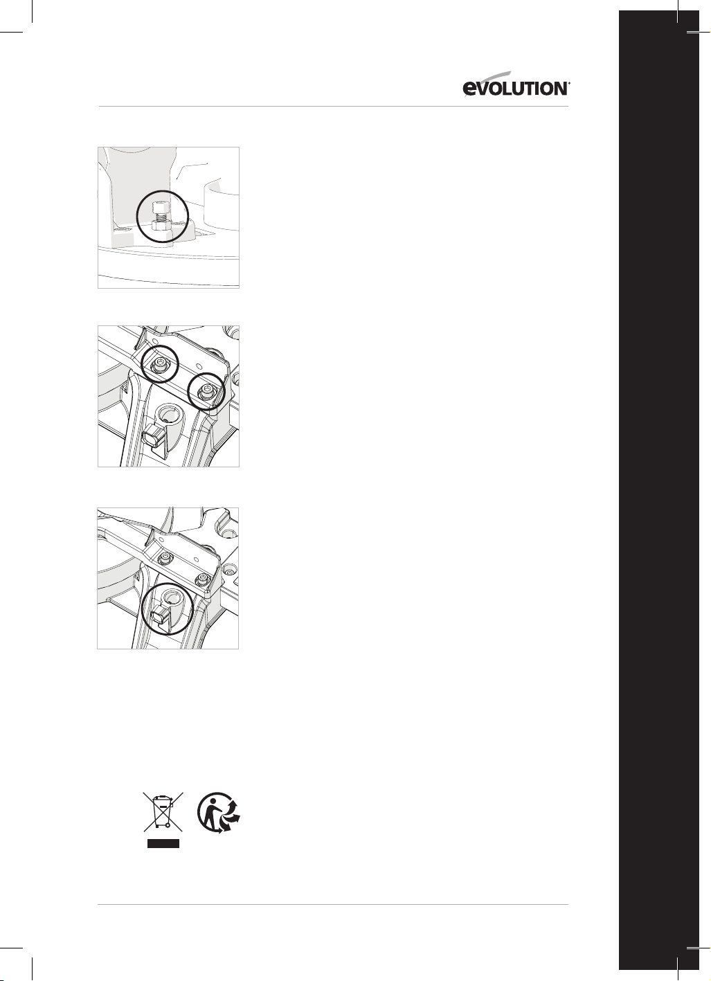
119
www.evolutionpowertools.com
PL
Jeśli konieczna jest regulacja:
Uwaga: Głowica tnąca będzie musiała być przechylona, aby można
było uzyskać dostęp do śruby regulującej blokady uchyłu 45°.
• Lekko poluzować nakrętkę śruby regulującej blokady uchyłu 45°.
(Rys. 23)
• Za pomocą klucza imbusowego należy przekręcić śrubę blokady
uchyłu zgodnie z ruchem wskazówek zegara lub w kierunku
przeciwnym, zgodnie z wymaganiami.
• Po uzyskaniu dokładnego wyrównania między tarczą a stołem
obrotowym dokręcić nakrętkę.
REGULACJA OGRANICZNIKA (Rys. 24a i 24b)
Ogranicznik jest przymocowany do podstawy maszyny za pomocą
czterech śrub z łbem kulistym, po dwie z każdej strony. Śruby te
umieszczone są w wydłużonych otworach, które umożliwiają zmianę
położenia ogranicznika w razie potrzeby.
Ogranicznik należy ustawić dokładnie pod kątem 90° względem
prawidłowo zamontowanej tarczy. Do prawidłowego umieszczenia
ogranicznika potrzebny będzie precyzyjny kątomierz (nie wchodzi
w skład zestawu).
Aby zmienić pozycję ogranicznika, należy:
• Ustawić stół obrotowy na kąt ukośny 0°.
• Ustawić głowicę tnącą na kąt uchyłu 0°.
• Lekko poluzować cztery śruby ogranicznika z łbem kulistym.
• Opuścić głowicę tnącą do najniższej pozycji.
• Sprawdź wyrównanie ogranicznika z tarczą za pomocą
kątomierza.
• W razie potrzeby wyrównać ogranicznik, a następnie dokręcić
śruby z łbem kulistym.
KONSERWACJA I REGULACJA
OSTRZEŻENIE: Przed przystąpieniem do jakichkolwiek czynności
konserwacyjnych lub regulujących należy upewnić się, że
urządzenie jest odłączone od źródła zasilania.
Czyszczenie
Należy wyczyścić urządzenie po każdym użyciu. Należy usunąć
pył itp. ze wszystkich widocznych części urządzenia za pomocą
odkurzacza. Odkurzacz może zostać podłączony do wejścia
do usuwania pyłu z tyłu urządzenia. Powinno to usunąć
zanieczyszczenia z wewnętrznych części maszyny. Nie wolno używać
rozpuszczalników do czyszczenia plastikowych części, ponieważ
może doprowadzić to do ich uszkodzenia. Do czyszczenia należy
używać jedynie miękkiej, lekko wilgotnej ściereczki.
Aby przedłużyć żywotność narzędzia, należy smarować części
obrotowe raz w miesiącu. Nie smarować silnika. Podczas czyszczenia
plastiku nie używać produktów żrących.
OSTRZEŻENIE: Nie wolno dopuścić do kontaktu wody z
urządzeniem.
OCHRONA ŚRODOWISKA
Odpady produktów elektrycznych nie powinny być utylizowane
razem zodpadami gospodarstwa domowego. Jeżeli to możliwe,
poddać utylizacji. Wskazówki dotyczące recyclingu można uzyskać
od władz lokalnych lub dystrybutora.
Rys. 23
Rys. 24a
Rys. 24b
120
www.evolutionpowertools.com
DEKLARACJA ZGODNOŚCI WE
Producent artykułu objętego niniejszą deklaracją:
UK: Evolution Power Tools Ltd. Venture One, Longacre Close, Holbrook Industrial Estate, Sheeld, S20 3FR.
FR: Evolution Power Tools SAS. 61 Avenue Lafontaine, 33560, Carbon-Blanc, Bordeaux, Francja.
Producent deklaruje niniejszym, że urządzenie, jak opisano w niniejszej deklaracji, spełnia wszystkie odpowiednie przepisy
dyrektywy maszynowej i innych odpowiednich dyrektyw wymienionych poniżej.
Producent oświadcza, że urządzenie, jak opisano w niniejszym oświadczeniu, w stosownych przypadkach spełnia
odpowiednie przepisy w zakresie ochrony zdrowia i bezpieczeństwa.
Dyrektywy objęte niniejszą deklaracją zostały wyszczególnione poniżej:
2006/42/WE. Dyrektywa maszynowa.
2014/30/UE. Dyrektywa w sprawie kompatybilności elektromagnetycznej.
Dyrektywa w sprawie ograniczenia stosowania niektórych niebezpiecznych
substancji w sprzęcie elektrycznym i elektronicznym (dyrektywa RoHS).
2012/19/UE. Dyrektywa w sprawie zużytego sprzętu elektrycznego i elektronicznego (WEEE).
Urządzenie jest zgodne z obowiązującymi wymaganiami określonymi w następujących
dokumentach:
EN 61029-1:2009+A11• EN 61029-2-11:2012+A11• EN 55014-1:2017+A11:2020 •
EN IEC 55014-1:2021 • EN IEC 55014-2:2021 • EN IEC 61000-3-2:2019+A1 •
EN IEC 61000-3-11:2019
EC type approval to 2006/42/EC Article 12 Section 3b Machinery
TÜV Rheinland LGA Products GmbH - Tillystraße 2 - 90431 Nürnberg
No.: 0197 Reg. No.: BM 50592380 0001
Dane produktu
Opis: UNIWERSALNA PILARKA STOŁOWA/UKOŚNICA R210MTS G2 210 mm
Nr modelu Evolution: 116-0001, 116-0002, 116-0003, 116-0004
Nazwa marki: EVOLUTION
Napięcie: 220-240 V~ 50 Hz
Moc wejściowa: 1500 W
Dokumentacja techniczna, wykazująca że produkt spełnia wymagania dyrektywy, została opracowana i jest dostępna
do wglądu dla właściwych organów egzekwowania prawa oraz potwierdza, że nasza dokumentacja techniczna zawiera
dokumenty wymienione powyżej oraz że są to właściwe normy dla produktu zgodnie z powyższymi informacjami.
Imię, nazwisko iadres posiadacza dokumentów technicznych.
Podpisano: Pismo drukowane: Barry Bloomer
Dyrektor Łańcucha Dostaw i Zakupów
Data: 8 lutego 2022 r.
UK: Evolution Power Tools Ltd. Venture One, Longacre Close, Holbrook Industrial Estate, Sheeld, S20 3FR.
FR: Evolution Power Tools SAS. 61 Avenue Lafontaine, 33560, Carbon-Blanc, Bordeaux, Francja.
2011/65/UE. i
2015/863/UE.

121
www.evolutionpowertools.com
PL

122
www.evolutionpowertools.com
BELANGRIJK
Lees deze gebruiksaanwijzing en
veiligheidsvoorschriften zorgvuldig en in zijn
geheel door.
Bent u onzeker over hoe u bepaalde functies van
dit gereedschap moet gebruiken, dan is het voor
uw eigen veiligheid aanbevolen de relevante
technische hulplijn te raadplegen. U vindt het
nummer hiervan op de website van Evolution
Power Tools.
We bedienen meerdere hulplijnen binnen onze
wereldwijde organisatie. U kunt voor technische
hulp echter ook uw leverancier raadplegen.
WEB
www.evolutionpowertools.com
E-MAIL:
VK:customer[email protected]
GARANTIE
Gefeliciteerd met de aankoop van een Evolution
Power Tool apparaat. Registreer uw product
'online' zoals uitgelegd in de folder die bij de
machine is gevoegd. Dit stelt u in staat om de
garantieperiode van uw machine te valideren
op de Evolution website door uw gegevens in te
voeren en zo een snelle service te garanderen als
u deze ooit nodig hebt.
Wij danken u hartelijk dat u voor een product van
Evolution Power Tools hebt gekozen.
Evolution Power Tools behoudt zich het recht
voor om verbeteringen en aanpassingen aan het
product door te voeren zonder voorafgaande
kennisgeving.
De details van de algemene voorwaarden van
de garantie kunt u raadplegen in de folder
voor registratie voor de garantie en/of op de
verpakking.

123
www.evolutionpowertools.com
NL
SPECIFICATIES
MACHINE VK / EU
Motor (220-240 V ~ 50 Hz) 1500 W
Onbelast toerental 3800 min
-1
Gewicht 13 kg
SNIJCAPACITEITEN VK / EU
Plaatstaal - maximale dikte 3 mm
Plaatstaal - maximale hardheid 210 HB
MAXIMALE SNIJCAPACITEIT (ALUMINIUM, HOUT EN PVC)
CONFIGURATIE VERSTEKZAAG
AFSCHUINING VERSTEKZAAG VK / EU
0° 0° 55 x 120 mm
45° 0° 35 x 120 mm
0° 45° links 55 x 65 mm
0° 45° rechts 55 x 55 mm
45° 45° links 35 x 30 mm
45° 45° rechts 35 x 70 mm
MAXIMALE SNIJCAPACITEIT - CONFIGURATIE TAFELZAAG
SNIJCAPACITEITEN VK / EU
Hout - maximale dikte 40 mm
AFMETINGEN VAN BLAD VK / EU
Diameter 210 mm
Boring 25.4 mm
Aantal tanden 20
Insnijding 1.7 mm
GELUID- EN TRILLINGSDATA
Geluidsdruk L
P
A 103 dB(A); K=3 dB(A)
Geluidsvermogensniveau L
W
A 116 dB(A); K=3 dB(A)
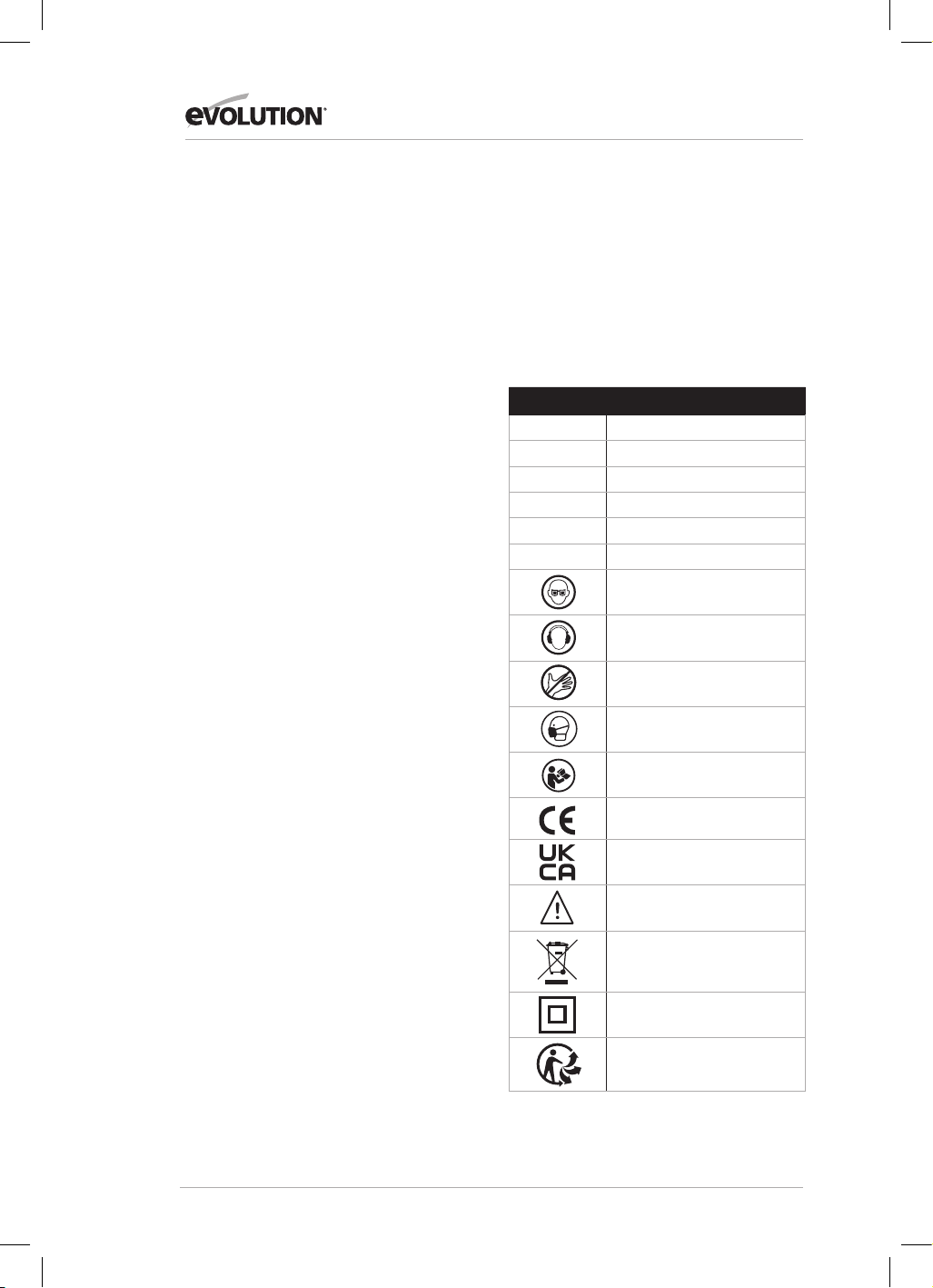
124
www.evolutionpowertools.com
De opgegeven geluidsemissiewaarden zijn
gemeten volgens een standaard testmethode
(EN 61029-1, EN 61029-2-11) en kunnen
worden gebruikt voor het vergelijken van het
ene apparaat met het andere.
WAARSCHUWING: de geluidsemissie tijdens
het daadwerkelijke totaal gebruik van het
elektrische gereedschap kan afwijken van de
aangegeven totaalwaarde. Dit is afhankelijk
van de manier waarop het instrument gebruikt
wordt en vooral welk soort werkstuk verwerkt
wordt.
Het is noodzakelijk om de
veiligheidsvoorschriften waar te nemen om
de bediener te beschermen die gebaseerd zijn
op een inschatting van de blootstelling in de
werkelijke gebruiksomstandigheden (rekening
houdend met alle delen van de gebruikscyclus,
zoals wanneer het gereedschap uitgeschakeld
wordt en wanneer het stationair draait,
bovenop de ingeschakelde tijd).
LABELS EN SYMBOLEN
WAARSCHUWING: dit apparaat niet
gebruiken als er enig waarschuwings- en/
of instructielabel ontbreekt of beschadigd is.
Neem contact op met Evolution
Evolution Power Tools voor vervangende
labels.
Opmerking: alle of sommige van de volgende
symbolen kunnen in de handleiding of op het
product getoond worden.
Symbool Omschrijving
V
Volt
A
Ampère
Hz
Hertz
Min
-1
Snelheid
~
Wisselstroom
n
o
Onbelast toerental
Draag een veiligheidsbril
Draag gehoorbescherming
Niet aanraken
Draag stofbescherming
Lees de instructies
CE-certificatie
UKCA-certificatie
Waarschuwing
Afval van elektrische en
elektronische apparatuur
Dubbel geïsoleerd
Triman - afvalophaling
en recycling

125
www.evolutionpowertools.com
NL
BEOOGD GEBRUIK VAN DEZE POWER TOOL
WAARSCHUWING: dit product is een
handbediende samengestelde verstekzaag
en is ontworpen om gebruikt te worden met
speciale zaagbladen van Evolution. Gebruik
alleen accessoires ontworpen voor deze
machine en/of specifiek aanbevolen door
Evolution Power Tools Ltd.
Wanneer deze zaagmachine van het juiste
zaagblad is voorzien, kan ze gebruikt worden
voor het zagen van:
Plaatstaal
Aluminium
Hout
Plastic
VERBODEN GEBRUIK VAN DIT
ELEKTRISCHE GEREEDSCHAP
WAARSCHUWING: dit product is een
handbediende samengestelde verstekzaag
en mag alleen als zodanig gebruikt worden.
Het mag op geen enkele manier worden
aangepast of worden gebruikt voor het
aandrijven van andere apparatuur of andere
accessoires die niet worden genoemd in deze
gebruiksaanwijzing.
WAARSCHUWING: deze machine is
niet bedoeld om gebruikt te worden
door personen (inclusief kinderen) met
verminderde lichamelijke, zintuiglijke of
mentale vaardigheden, of met een gebrek aan
kennis en ervaring, tenzij ze onder toezicht
staan of instructies hebben ontvangen over
het veilige gebruik van de machine door een
persoon verantwoordelijk voor hun veiligheid,
die bevoegd is om het toestel veilig te
gebruiken.
Kinderen moeten onder toezicht staan zodat
ze geen toegang hebben tot deze machine en
mogen er niet mee spelen.
ELEKTRISCHE VEILIGHEID
Deze machine is uitgerust met een voor de
doelmarkt geschikte stekker en netsnoer.
Als het netsnoer beschadigd is, moet het
worden vervangen door een speciaal
snoer of assemblage van de fabrikant of de
servicedienst.
GEBRUIK BUITENSHUIS
WAARSCHUWING: voor uw bescherming
mag dit gereedschap, indien het buitenshuis
wordt gebruikt, niet worden blootgesteld aan
regen of worden gebruikt in een vochtige
omgeving.
Plaats het gereedschap niet op vochtige
oppervlakken.
Gebruik een schone, droge werkbank indien
deze beschikbaar is.
Gebruik voor extra bescherming een
aardlekschakelaar die de stroomtoevoer zal
onderbreken als de lekstroom groter is dan 30
mA voor 30 ms. Controleer altijd de werking
van de aardlekschakelaar voordat u de
machine gebruikt.
Indien een verlengsnoer nodig is moet het een
geschikt type zijn voor gebruik buitenshuis en
van een label zijn voorzien dat dit aangeeft.
De instructies van de fabrikant moeten
worden opgevolgd bij het gebruik van een
verlengsnoer.
ALGEMENE VEILIGHEIDSINSTRUCTIES VOOR
ELEKTRISCH GEREEDSCHAP
• Volg al deze instructies voor en tijdens het
werken met de zaag.
• Bewaar deze instructies op een veilige plek.
• Vermijd lichaamscontact met geaarde
componenten.
• Wanneer de apparatuur niet wordt
gebruikt, moet deze op een droge
vergrendelde plaats bewaard worden,
buiten het bereik van kinderen.
• U werkt beter en veiliger als u uw
gereedschap scherp en schoon houdt.
Controleer de stroomkabel regelmatig
en laat deze door een geautoriseerde
specialist vervangen bij de eerste tekenen
van schade.
• Inspecteer verlengkabels regelmatig en
vervang ze direct indien ze beschadigd zijn.
• Gebruik bij werk buitenshuis alleen
verlengkabels die zijn goedgekeurd
voor buiten gebruik en als zodanig zijn
aangemerkt.
• Concentreer op wat u aan het doen
bent. Ga verstandig te werk. Gebruik het
gereedschap nooit als u vermoeid bent.
• Gebruik nooit gereedschap met een
schakelaar die niet aan of uit gezet kan
worden.
• Let op! Gebruik van ingestoken
gereedschap en accessoires anders dan
bedoeld kan risico op letsel met zich
meedragen.
• Het apparaat is uitgerust met een
veiligheidsschakelaar om te voorkomen
dat het per ongeluk opnieuw ingeschakeld
wordt na een stroomonderbreking (in
tafelzaagmodus).
• Gebruik de zaag nooit om rondom hout
te zagen.
• controleer de stroomkabel. Gebruik nooit

126
www.evolutionpowertools.com
een kapotte of beschadigde stroomkabel.
• Trek nooit aan de kabel om de stekker uit
het stopcontact te trekken. Houd de kabel
uit de buurt van hitte, olie en scherpe
randen.
• We raden aan dat u antislipschoenen draagt
als u buitenshuis werkt.
• Draag lang haar in een haarnetje.
• Vermijd abnormale werkhoudingen.
• Een rommelige werkruimte kan leiden tot
ongelukken.
• Laat niemand anders, zeker geen kinderen,
de tool of de stroomkabel aanraken. Houd
kinderen uit de buurt van uw werkplek.
• De splitter is een belangrijk
veiligheidsapparaat. Het geleidt het
werkstuk niet alleen, het voorkomt ook dat
de zaagsnede sluit achter de zaag zodat
er geen terugslag is van het werkstuk. Kijk
naar de dikte van de splitter, deze mag
nooit dunner zijn dan de zaagbehuizing of
dikker dan de breedte van de zaagsnede.
• De bovenste zaagbeveiliging moet voor
iedere snede omlaag gebracht worden over
het werkstuk.
• Zorg dat u een duwstok gebruikt bij het
zagen van dunne werkstukken minder dan
120 mm in breedte of een duwblok bij het
zagen van dunne werkstukken minder dan
30 mm in breedte.
BELANGRIJK: gebruik deze zaag nooit om
invalcirkels te maken.
• Sta altijd aan de zijkant van het zaagblad bij
het werken met de verstekzaag.
• Zorg dat snijresten niet in de
zaagbladkroon vast komen te zitten, omdat
deze in de omgeving kunnen worden
geslingerd.
• Als de zaagspleet versleten is, vervang dan
het tafelinzetstuk.
• Om letsel door rondvliegend zaagsel en
snijresten te voorkomen moet de zaag
alleen gebruikt worden met een geschikt
vacuümextractiesysteem of standaard
industriële stofzuiger.
• Trek altijd de stekker uit het stopcontact
voor het aanpassen of onderhouden van
het apparaat.
• Geef deze veiligheidsregulaties aan
iedereen die met het apparaat werkt.
• Gebruik deze zaag niet voor het zagen van
vuurhout.
• Let op! Handen en vingers kunnen verwond
worden door het draaiende zaagblad.
• Voordat u het apparaat voor de eerste keer
gebruikt, controleer of het aangegeven
voltage op de typeplaat overeenkomt met
het voltage van het stroomnetwerk.
• Als u een verlengkabel moet gebruiken,
zorg dat de kabeldoorsnede groot genoeg
is voor de stroombehoefte van de zaag.
Minimale doorsnede: 1,0 mm2.
• Als u een kabelhaspel gebruikt, moet de
hele kabel van de haspel afgerold worden.
• Draag de zaag nooit bij de kabel.
• Laat de zaag niet in de regen liggen
en niet gebruiken in vochtige of natte
omstandigheden.
• Zorg voor goede verlichting.
• Zaag nooit in de buurt van brandbare
vloeistoffen of gassen.
• Draag geschikte werkkleren. Losse kleren
of sieraden kunnen verstrikt raken in het
draaiende zaagblad.
• Gebruikers moeten ten minste 18 jaar zijn.
Stagiairs van ten minste 16 jaar mogen het
apparaat alleen onder supervisie gebruiken.
• Houd kinderen uit de buurt van het
apparaat als het aangesloten is op de
stroomvoorziening.
BELANGRIJK:
• controleer de stroomkabel. Gebruik nooit
een kapotte of beschadigde stroomkabel.
• Houd uw werkplek vrij van houtresten en
alle onnodige objecten.
• Personen die met het apparaat werken
mogen niet afgeleid worden.
• Kijk naar de richting van draaiing van de
motor en het zaagblad.
• Nadat u de motor hebt uitgeschakeld, mag
u nooit het zaagblad afremmen door druk
op de zijkant uit te voeren.
• Gebruik alleen bladen die goed scherp
zijn en geen scheuren of vervormingen
vertonen.
• Het apparaat moet alleen gebruikt worden
met tools die voldoen aan EN 847-1
• Kapotte zaagbladen moeten direct
vervangen worden.
• Gebruik nooit zaagbladen die niet voldoen
aan de gegevens gespecificeerd in deze
handleiding.
• Zorg dat de pijl op het zaagblad
overeenkomt met de pijl op het apparaat.
• Zorg dat het zaagblad de draaitafel bij
geen enkele instelling raakt. Om dit te doen
moet u de stroomstekker eruit trekken en
het zaagblad met de hand in de 45° positie
en de 90° positie. Indien nodig moet u de
zaagkop opnieuw afstellen.
• Het is essentieel dat alle apparaten die
gebruikt worden om het zaagblad te
bedekken in goed werkende conditie zijn.
• Klem de gescharnierde beschermkap nooit
in de open positie.

127
www.evolutionpowertools.com
NL
GEZONDHEIDSADVIES
WAARSCHUWING: bij het gebruik van deze
machine kunnen stofdeeltjes vrijkomen.
Afhankelijk van de materialen waarmee u
werkt, kan dit stof zeer schadelijk zijn. Vraag
professioneel advies indien u denkt dat de
verf waarmee het oppervlak van het te zagen
materiaal bedekt is, lood bevat. Verf gebaseerd
op lood mag alleen verwijderd worden door
een deskundige. Wij raden u aan om niet zelf te
proberen deze te verwijderen. Wanneer het stof
op oppervlakken neervalt, kan contact van uw
hand met uw mond leiden tot de inname van
lood.
Blootstelling aan zelfs lage niveaus van lood
kan leiden tot onomkeerbaar hersenletsel en
beschadiging van het zenuwstelsel. Vooral jonge
en ongeboren kinderen zijn kwetsbaar. We raden
u aan de risico's verbonden aan de materialen
waarmee u werkt goed in te schatten en het risico
op blootstelling te beperken. Omdat sommige
materialen stof kunnen produceren die schadelijk
kunnen zijn voor uw gezondheid,
raden we het gebruik van een goedgekeurd
masker aan met vervangbare filters tijdens het
gebruik van
dit apparaat.
Werk steeds:
• In een goed-geventileerde ruimte.
• Met goedgekeurde veiligheidsuitrustingen,
zoals stofmaskers die speciaal ontworpen zijn
om microscopische deeltjes te filteren.
WAARSCHUWING: de werking van een
verstekzaag kan ertoe leiden dat er voorwerpen
richting uw ogen worden geprojecteerd, wat
kan leiden tot ernstige oogschade. Voordat u
het elektrische gereedschap gebruikt, draag
altijd een veiligheidsbril, een veiligheidsbril met
zijbescherming of een volledig gelaatsscherm
indien nodig.
EXTRA VEILIGHEIDSINSTRUCTIES
VERSTEKZAGEN
De volgende specifieke veiligheidsinstructies voor
verstekzagen zijn gebaseerd op de vereisten van
EN 61029-2:11
BLADVEILIGHEID
WAARSCHUWING: Roterende zaagbladen zijn
extreem gevaarlijk en kunnen ernstig letsel en
amputatie veroorzaken. Houd uw vingers en
handen te allen tijden ten minste 150 mm van het
zaagblad vandaan. Probeer gezaagd materiaal
nooit te verwijderen totdat de zaagkop zich
in de hoogste stand bevindt, de beschermkap
volledig gesloten is en het zaagblad gestopt is
met bewegen.
Gebruik alleen zaagbladen die aanbevolen
worden door de fabrikant en zoals beschreven in
deze handleiding en die voldoen aan de vereisten
van EN 847-1:
Gebruik geen zaagbladen die beschadigd of
misvormd zijn, aangezien ze zouden kunnen
versplinteren en ernstig letsel aan de operator en
omstanders kunnen veroorzaken.
Gebruik geen zaagbladen die vervaardigd zijn uit
snelstaal (HSS).
Indien het tafelinzetstuk beschadigd of versleten
is, moet het worden vervangen door een
identieke eenheid, beschikbaar bij de fabrikant
beschreven in deze handleiding.
PERSOONLIJKE
BESCHERMINGSMIDDELEN (PBM)
Er moet gehoorbescherming worden gedragen
om het risico op blijvende gehoorschade te
verminderen.
Er moet oogbescherming worden gedragen,
om de mogelijkheid op het verlies van het
gezichtsvermogen veroorzaakt door uitgeworpen
splinters te voorkomen.
Ademhalingsbescherming wordt ook
aanbevolen aangezien sommige hout- en
houtsoortproducten, met name MDF (medium-
density fibreboard), stof kunnen produceren dat
schadelijk voor uw gezondheid kan zijn.
Wij raden het gebruik van een goedgekeurd
gezichtsmasker aan bij het gebruik van deze
machine, in combinatie met het gebruik van een
stofafzuigingsinstallatie.
Handschoenen moeten worden gedragen bij
het hanteren van messen of ruw materiaal. Het
is aanbevolen om zaagbladen in een houder
te dragen, voor zover dit mogelijk is. Het is niet
aanbevolen om handschoenen te dragen bij het
bedienen van de verstekzaag.
VEILIGE BEDIENING
Zorg er altijd voor dat u het juiste zaagblad
hebt geselecteerd voor het materiaal dat wordt
gesneden.
Gebruik deze verstekzaag niet voor het zagen
van materialen die niet in deze handleiding zijn
gespecificeerd.
Verzeker bij het transporteren van een
verstekzaag dat de zaagkop vergrendeld is in
de positie 90 graden omlaag (verzeker bij een
schuivende verstekzaag dat de schuifbalken
vergrendeld zijn). Til de machine op door de
buitenste randen van de basis met beide handen

128
www.evolutionpowertools.com
vast te pakken (als een schuivende verstekzaag
wordt gebruikt, transporteer dan met de
meegeleverde handgrepen). De machine mag
onder geen enkele omstandigheid opgetild of
getransporteerd worden met gebruik van de
rechthoekige beschermkap of een onderdeel van
zijn besturingsmechanisme.
Controleer voor elk gebruik de werking
van de intrekbare afscherming en het
bedieningsmechanisme en eventuele schade, en
controleer of alle bewegende onderdelen soepel
en correct werken.
Houd de werkbank en de vloer schoon en
verwijder alle vuilresten zoals zaagsel, spaanders
en afgezaagde stukken.
Controleer altijd en zorg ervoor dat de op het
zaagblad aangegeven snelheid ten minste gelijk
is aan de snelheid zonder belasting die op de
verstekzaag is aangegeven.
Onder geen enkele omstandigheid mag u
een zaagblad gebruiken, ontworpen voor een
snelheid die lager is dan de snelheid zonder
belasting aangegeven op de verstekzaag.
Wanneer het gebruik van afstands- en
reductieringen nodig is, moeten deze geschikt
zijn voor het beoogde doel en voldoen aan de
aanbevelingen van de fabrikant.
Het zaagblad zal alleen vervangen worden zoals
beschreven in de handleiding.
Probeer afgezaagde stukken of andere stukken
van het werkstuk nooit te verwijderen totdat
de zaagkop zich in de bovenpositie bevindt, de
beschermkap volledig gesloten is en het zaagblad
gestopt is met bewegen.
CORRECT EN VEILIG ZAGEN
Indien mogelijk, probeer het werkstuk altijd op
de zaagtafel te bevestigen, met gebruik van de
meegeleverde werkklem.
Zorg er altijd voor dat vóór elke snede de
verstekzaag in een stabiele positie is gemonteerd.
Indien nodig kan de verstekzaag worden
gemonteerd op
een houten voet of werkbank of worden
bevestigd aan een verstekzaagstandaard zoals
beschreven in deze handleiding.
Lange werkstukken moeten ondersteund worden
op de meegeleverde werksteunen of op geschikte
extra werksteunen.
WAARSCHUWING: als er onderdelen ontbreken,
gebruik dan uw apparaat niet voordat de
ontbrekende onderdelen zijn vervangen. Het niet
opvolgen van deze regel kan leiden tot ernstig
lichamelijk letsel.
AANVULLEND VEILIGHEIDSADVIES
UW VERSTEKZAAG DRAGEN
Veiligheidsadvies
• Ondanks het compacte formaat is deze zaag
zwaar. Om het risico op rugletsel te verlagen,
moet u bekwame hulp zoeken bij het optillen
van de zaag.
• Om het risico op rugletsel te verlagen, moet
u het gereedschap dicht bij uw lichaam
houden bij het optillen. Ga door uw knieën
zodat u vanuit uw benen kan tillen, niet vanuit
uw rug. Til het toestel op met gebruik van de
handgreepgebieden aan de beide kanten van
de machinevoet.
• Draag de verstekzaag nooit aan zijn
stroomsnoer. Door de tool aan het
stroomsnoer te dragen kunt u de isolatie of de
draad beschadigen, wat een elektrische schok
of vuur kan veroorzaken.
• Voordat u de zaag beweegt, moet u
de vergrendelingsschroeven voor het
verstek- en schuinzagen aandraaien om
onverwachte bewegingen te voorkomen.
• Vergrendel de zaagkop in zijn laagste
positie. Controleer of de vergrendelpin van
de zaagkop volledig geëngageerd is in zijn
opening.
WAARSCHUWING: gebruik de bladbeschermer
niet als een 'hefpunt'. De stroomkabel moet uit
het stopcontact verwijderd worden voordat u de
machine gaat verplaatsen.
• Vergrendel de zaagkop in de onderpositie met
gebruik van de vergrendelpin van de zaagkop.
• Maak de vergrendelingsschroef van de
verstekhoek los. Draai de tafel naar een van zijn
maximale instellingen.
• Vergrendel de tafel in zijn positie met gebruik
van de vergrendelingsschroef.
• Gebruik de twee handvatopeningen aan de
zijkanten van het voetstuk van de machine,
voor het verplaatsen van de machine.
Plaats de zaag op een stevig stationair
werkoppervlak en controleer de zaag
zorgvuldig.
Controleer met name het functioneren van alle
veiligheidsfuncties van de machine voordat u de
machine opnieuw bedient.
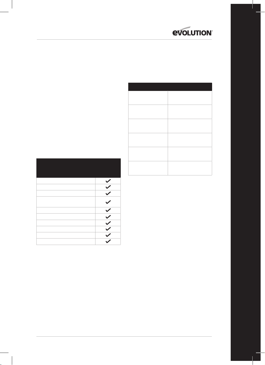
129
www.evolutionpowertools.com
NL
AAN DE SLAG - UITPAKKEN
Let op: deze verpakking bevat scherpe
voorwerpen. Wees voorzichtig bij het
uitpakken. Verwijder de machine, samen met
de meegeleverde accessoires, uit de verpakking.
Controleer zorgvuldig of de machine zich in
goede conditie bevindt en controleer of alle
accessoires die in deze handleiding worden
genoemd aanwezig zijn.
Zorg er ook voor dat alle accessoires compleet
zijn. Indien er onderdelen ontbreken, moet
de machine en zijn accessoires samen in hun
originele verpakking teruggebracht worden
naar de leverancier. Gooi de verpakking niet
weg. Bewaar deze zorgvuldig tijdens de
garantieperiode. Gooi de verpakking op een
milieuverantwoorde manier weg. Recycle indien
mogelijk. Laat kinderen niet met de lege plastic
zakjes spelen, in verband met verstikkingsgevaar.
GELEVERDE ITEMS
Omschrijving
116-0001,
116-0002,
116-0003,
116-0004
Gebruiksaanwijzing
Vastzetklem
Duwstok
Penspanner
(Blad vervangen)
Tweezijdige inbussleutel 6-5 mm
Multi-inzetbaar zaagblad
Parallelaanslag
Stofzak
Tafelzaagbescherming
Uitbreidingen zijkant basis x 2
EXTRA ACCESSOIRES
Naast de standaardonderdelen die bij deze
machine worden geleverd, zijn de volgende
accessoires ook verkrijgbaar via de webshop van
Evolution op www.evolutionpowertools.com
of bij uw plaatselijke verkoper.
Omschrijving Onderdeelnr.
RAGE Multi-Materiaal
TCT-zaagblad
RAGEBLADE210MULTI
210 mm algemeen
zaagblad voor hout
GW210TCT-30
210 mm Fijn
zaagblad voor hout
FW210TCT-40
210 mm
Diamantschijf
D210CON
Standaard voor
verstekzaag
005-0001
Standaard voor
verstekzaag +
005-0005

130
www.evolutionpowertools.com
R210MTS-G2 MACHINEOVERZICHT
1
3
8
1. ZAAGHANDVAT
2. DRAAITAFEL
3. INTREKBARE ONDERSTE BESCHERMKAP
4. VERSTEKHOEKVERGRENDELHENDEL
5. VERSTEKZAAG HOEKSCHAAL
6. ONTGRENDELINGSHENDEL ZAAGKOP
7. BORGPEN ZAAGKOP
8. OPSLAG DUWSTOK
9. TAFELZAAG AAN/UIT-SCHAKELAAR
10. VERSTEKZAAG AAN/UIT-TREKKER
2
9
10
4
6
5
7

131
www.evolutionpowertools.com
NL
R210MTS-G2 MACHINEOVERZICHT
1. TAFELBLAD
2. TAFELZAAGBESCHERMING
3. PARALLELAANSLAG
4. DUWSTOK
5. MODEPEN TAFEL/VERSTEK
6. AFKANT SNELSPANNER
7. ACHTERSTE STABILISERENDE ARM
8. WERKSTUKONDERSTEUNING (X 2)
9. OPBERGEN GEREEDSCHAP
10. PARALLELAANSLAG SNELSPANNERS (X 2)
11. TAFELBLADWEEGSCHAAL
2
4
3
1
7
8
9
5
6
10
10
11
11

132
www.evolutionpowertools.com
AAN DE SLAG
WAARSCHUWING: ONTKOPPEL ALTIJD DE VOEDING NAAR
DE ZAAGMACHINE VOORDAT U EVENTUELE AANPASSINGEN
AANBRENGT.
PERMANENTE MONTAGE VAN DE R210MTS-G2
TAFEL/VERSTEKZAAG (Afb. 1)
WAARSCHUWING: om het risico op verwondingen door
onverwachte zaagbewegingen te verminderen, plaatst u de zaag
op de gewenste locatie op een werkbank of een andere geschikte
machinestandaard. De basis van de zaag heeft vier gaten voor de
bevestiging van de verstekzaag. Als de zaag op één locatie moet
worden gebruikt, bevestigt u deze met behulp van geschikte
bevestigingen (niet meegeleverd) permanent aan de werkbank of
machinestandaard.
1. Draai de verstek- en afkantvergrendeling aan.
2. Positioneer de zaag zo dat andere mensen er niet achter
kunnen staan. Rondgeslingerde resten kunnen mensen
verwonden.
3. Plaats de zaag op een stevig, vlak oppervlak waar er genoeg
ruimte is voor het hanteren en juiste ondersteunen van het
werkstuk.
4. Ondersteun de zaag zodat de tafel vlak is en de zaag niet
schommelt.
5. Bout of klem de zaag vast aan de steun.
ACHTERSTE STABILISERENDE BALK
Verleng de balk naar de achterkant van de machine (Afb. 2)
TAFELZAAGBESCHERMING
Om de tafelzaagbescherming te installeren:
• Gebruik de imbussleutel om de 2 imbusschroeven los te maken
• Installeer de tafelzaagbescherming (Afb. 3)
• Draai de imbusschroeven vast.
BLAD INSTALLEREN OF VERWIJDEREN
WAARSCHUWING: gebruik alleen echte Evolution-zaagbladen
ontworpen voor deze machine. Zorg ervoor dat de maximale
snelheid van het blad compatibel is met de machine. Voer deze
handeling alleen uit wanneer de machine is losgekoppeld van
het stroomnet.
Opmerking: het is aanbevolen dat de bediener beschermende
handschoenen draagt bij het hanteren van het zaagblad bij de
installatie of het vervangen van het zaagblad.
Om een blad te vervangen:
• Trek de pen eruit (Afb. 4) om de motor te ontgrendelen.
• Druk voorzichtig op de handgreep van de zaagkop.
• Trek de vergrendelingspen van de zaagkop uit en laat de
zaagkop naar de bovenste positie stijgen. (Afb. 5)
• Gebruik de penspanner (meegeleverd) om de buitenste
bladflens te bevestigen.
• Gebruik de imbussleutel (meegeleverd) om de asschroef los te
maken. (Afb. 6)
Afb. 1
1) Imbusbout
2) Veerring
3) Platte ring
4) Verstekzaagbasis
5) Werkbank
6) Platte ring
7) Verrring
8) Imbusmoer
9) Vergrendelingsbout
(1)
(2)
(3)
(4)
(5)
(6)
(7)
(8)
(9)
Afb. 2
Afb. 4
Afb. 3

133
www.evolutionpowertools.com
NL
Opmerking: de asschroef heeft een linkse schroefdraad. Draai
met de klok mee om los te maken en tegen de klok in om vast te
maken.
• Verwijder de asschroef en de buitenste bladflens.
• Trek de onderste beschermkap in door de
ontgrendelingshendel van de zaagkop in te drukken en de
onderste beschermkap naar boven te draaien om het blad
bloot te leggen.
• Verwijder het blad door het naar buiten te trekken om het
uiteinde van de as vrij te maken en dan omlaag en naar voren,
weg van de machine. (Afb. 7)
Spouwmes
Het spouwmes is een zeer belangrijk component en wordt
geïnstalleerd op de bovenste beschermkap. Het spouwmes
voorkomt dat het werkstuk vastloopt als het het blad passeert.
Inspecteer het spouwmes op regelmatige intervallen en vervang
het indien versleten of beschadigd.
Het spouwmes moet ingesteld worden zodat de kloof tussen de
zaagbladtanden en de rand van het spouwmes ongeveer 3 - 5
mm is. (Afb. 8)
Om het spouwmes af te stellen maakt u de twee
bevestigingsschroeven (Afb. 9) iets los met een imbussleutel.
Wanneer de uitlijning correct is, draait u de bevestigingsschroef
vast.
Opmerking: gebruik alleen een origineel Evolution bovenste
beschermkapassemblage, omdat dit een wezenlijk onderdeel
voor deze machine is. Niet-originele onderdelen kunnen
gevaarlijk zijn. Raadpleeg de hulplijn in geval van twijfel.
DE R210MTS-G2 CONFIGUREREN VOOR GEBRUIK ALS
VERSTEKZAAG
WAARSCHUWING: de volgende handeling alleen verrichten als
de machine van de stroomtoevoer losgekoppeld is.
Let op: de R210MTS-G2 heeft vele ingebouwde
veiligheidsfuncties en veiligheidsvergrendelingen.
Het is belangrijk dat de volgende instructies gelezen,
begrepen en gevolgd worden. Het niet uitvoeren van de
configuratieprocedure kan resulteren in schade aan de machine
en/of letsel van de gebruiker.
• Trek de pen eruit (Afb. 4) om de motor te ontgrendelen.
• Druk voorzichtig op de handgreep van de zaagkop.
• Trek de vergrendelingspen van de zaagkop uit en laat de
zaagkop naar de bovenste positie stijgen. (Afb. 5)
De R210MTS-G2 is nu klaar voor gebruik als verstekzaag.
WERKSTUKONDERSTEUNING
Werkstukondersteuningen moeten worden geïnstalleerd op
beide kanten van de machine (Afb. 10)
Afb. 5
Afb. 8
Afb. 6
Afb. 7
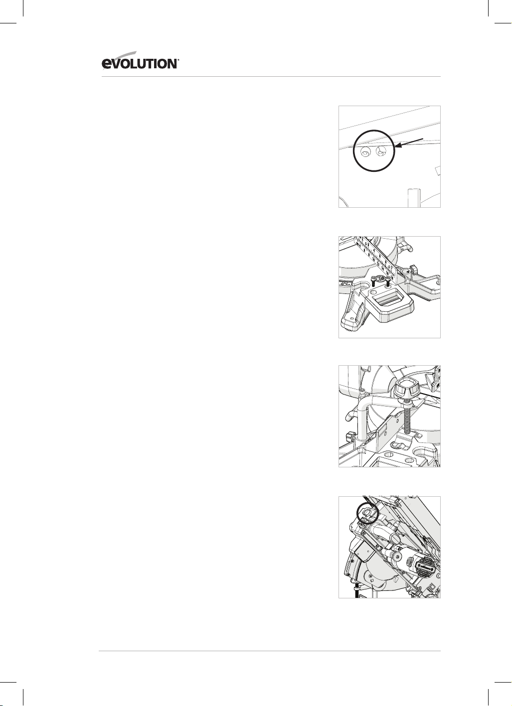
134
www.evolutionpowertools.com
VASTZETKLEM
Er wordt een vastzetklem meegeleverd met de R210MTS-G2.
Twee openingen (één aan elke kant) zijn in de achterkant van de
geleider van de machine opgenomen. (Afb. 11)
• Monteer de pijler van de klem op de bus die het beste past
bij de snijtoepassing, en zorg ervoor dat deze volledig naar
beneden wordt gedrukt.
• Draai de duimschroef van de geleider aan om de pijler van de
vastzetklem in de opening van de geleider te vergrendelen.
• Plaats het werkstuk op de draaiende tafel en tegen het hek.
• Stel de vastzetklem zo in dat het werkstuk veilig geklemd is op
de draaitafel.
• Controleer voor het zagen dat de klem niet interfereert met
het bladpad als de zaagkop omlaag gebracht wordt.
GEBRUIKSINSTRUCTIES VERSTEKZAAGCONFIGURATIE
1. De zaagkop ontgrendelen
Opmerking: indien geconfigureerd in de verstekzaagmodus
zal de zaagkop automatisch in de bovenste positie vergrendeld
worden waarbij de intrekbare onderste beschermkap de
zaagtanden helemaal bedekt.
Om de zaagkop te ontgrendelen, drukt u op de snelspanner van
de zaagkop en houdt u deze ingedrukt. (Afb. 12)
Druk voorzichtig op de handgreep van de zaagkop om de
zaagkop omlaag te brengen. De werking van de intrekbare
onderste beschermkap is automatisch, indien in contact met het
werkstuk.
2. Positionering van het lichaam en hand (Afb. 13)
• Plaats nooit uw handen in de 'geen handen zone' (minstens
150 mm verwijderd van het blad). Pictogrammen op de
draaitafel van de machine zijn bedoeld als ondersteuning voor
veilige werkpraktijken. Houd uw handen uit de buurt van het
pad van het zaagblad.
• Zet het werkstuk stevig tegen de geleider om beweging te
voorkomen. Gebruik een vastzetklem indien mogelijk, maar
controleer of het zo geplaatst is dat het niet interfereert
met het pad van het zaagblad of andere bewegende
machineonderdelen.
• Voordat u een snede gaat maken, voer eerst een
proefbeweging uit met de stroom uit, zodat u het pad van het
zaagblad kunt zien.
• Houd uw handen in positie totdat de AAN/UIT-trekker
losgelaten is en het zaagblad volledig gestopt is.
3. De werking van de trekkerschakelaar van de verstekzaag
Gebruik de schakelaar om de motor aan te zetten. Laat de
schakelaar los om de motor uit te zetten. (Afb. 14)
4. Hakzagen
De zaagkop wordt voorzichtig naar beneden geduwd om door
het werkstuk te zagen.
Afb. 11
Afb. 12
Afb. 10
Afb. 9

135
www.evolutionpowertools.com
NL
Afb. 13
• Plaats het werkstuk op de draaiende tafel en tegen de geleider
in de gewenste positie. Bevestig met klem(men).
• Pak het zaaghandvat vast.
• Zet de motor aan met de trekkerschakelaar en laat het blad de
volle operationele snelheid bereiken.
• Druk op de ontgrendelingshendel van de zaag en houd vast
om de zaagkop te ontgrendelen.
• Breng de zaagkop voorzichtig omlaag naar de laagste positie
en zaag door het werkstuk.
• Zet nadat het zagen is voltooid, de motor uit door de
trekkerschakelaar los te laten. Laat het zaagblad volledig tot
stilstand komen. Laat de zaagkop stijgen naar de hoogste
stand.
• Verwijder uw handen of het werkstuk alleen van de machine
als de zaagkop zich in de bovenste positie bevindt en
de zaagtanden volledig bedekt zijn door de intrekbare
beschermkap.
5. Transversaal zagen
Iedere hoek van 46˚ links tot 46˚ rechts is beschikbaar en een
gradenboogschaal kan aan de voorkant van de draaitafel
gevonden worden.
Positieve stops worden geleverd voor 0˚, 15˚, 22,5˚, 31,6˚ & 45˚
links en rechts van hoekbeweging.
Opmerking: de draaitafel moet altijd in positie vergrendeld
worden met de verstekhoekvergrendelhendel.
Om een verstekhoek te selecteren:
• Maak de vergrendelingsschroef van de verstekhoek los.
(Afb. 15)
• Draai de draaitafel naar de gewenste hoek.
• Draai de handgreep van de verstekhoek vast als de gewenste
hoek is geselecteerd.
Een versteksnede kan nu gemaakt worden met dezelfde
technieken zoals eerder beschrijven bij hakzagen.
6. Afschuinen
De zaagkop kan worden ingesteld op iedere hoek tot 47˚, alleen
aan de linkerkant.
De afkantsnelspanner bevindt zich aan de achterkant van de
machine.
Een gradenboog en aanwijzer zijn ingebouwd in het
afkantmechanisme om het afstellen te ondersteunen. (Afb. 16)
Om een afschuiningshoek in te stellen:
• Draai de vergrendelingshendel los.
• Kantel de zaagkop naar de benodigde hoek. Gebruik de
gradenboog om het instellen te ondersteunen.
• Zorg dat de vergrendelingshendel stevig vast zit als de
gewenste hoek is bereikt.
Een afschuiningssnede kan nu gemaakt worden met dezelfde
technieken zoals eerder beschrijven.
Opmerking: voer altijd eerst een test uit met de machine
uitgeschakeld, zodat het pad van het blad gecontroleerd kan
worden. Voor sommige afschuinings- en samengestelde snedes
No-Hands ZoneNo-Hands Zone
Afb. 14
Afb. 15
Afb. 16

136
www.evolutionpowertools.com
moet de vastzetklem aan de rechterkant van de zaagkop worden
gepositioneerd. Dit kan nodig zijn om interferentie met het blad
en andere onderdelen van de machine te voorkomen als de
zaagkop omlaag gebracht wordt.
7. Samengesteld zagen
Een samengestelde snede is een combinatie van verstekzagen en
afschuinen.
• Stel de verstekhoek in zoals eerder beschreven.
• Stel de afschuiningshoek in zoals eerder beschreven.
• Zorg dat alle afstellings-/vergrendelingsschroeven goed
vast zitten, en voer een test uit om het pad van het blad te
controleren.
• Maak de snede zoals eerder beschreven.
8. Vastgelopen materiaal verwijderen
• Stop de verstekzaag en wacht tot het blad helemaal gestopt is.
• Indien mogelijk, laat de zaagkop stijgen naar de hoogste
stand.
• Haal de stekker van de verstekzaag uit het stopcontact.
• Verwijder voorzichtig alle vastgelopen materiaal uit de
machine.
DE R210MTS-G2 CONFIGUREREN VOOR GEBRUIK ALS
TAFELZAAG
WAARSCHUWING: zaag geen metaal of metallic-materialen als
de machine geconfigureerd is als tafelzaag.
WAARSCHUWING: de volgende handeling alleen verrichten als
de machine van de stroomtoevoer losgekoppeld is.
• Zorg dat de draaitafel op 0˚ verstekhoek en dat de zaagkop is
ingesteld op 0˚ afschuiningshoek.
• Breng de zaagkop omlaag naar de onderste positie. Druk de
bevestigingspen van de zaagkop in de opening. (Afb. 17)
• Trek de motorbevestigingspen in en draai de motor naar
boven.
(Afb. 18)
De R210MTS-G2 is nu klaar voor gebruik als tafelzaag. (Afb. 19)
Afb. 18
Afb. 17
Afb. 19

137
www.evolutionpowertools.com
NL
GELEIDERASSEMBLAGE ALS PARALLELAANSLAG
Om de geleiderassemblage als parallelaanslag te gebruiken moet
de frontplaat precies zijn uitgelijnd met het blad.
WAARSCHUWING: de volgende handeling alleen verrichten als
de machine van de stroomtoevoer losgekoppeld is.
Om de parallelaanslag uit te lijnen:
• Stel de afschuining in op 0˚ met de maatverdeling op de tafel.
• Lijn de geleider uit met de maatverdeling op de tafel en
vergrendel in positie met 2 snelspanners.
ELEMENTAIRE VERRICHTINGEN TAFELZAAG
WAARSCHUWING: zaag geen metaal of metallic-materialen als
de machine geconfigureerd is als tafelzaag.
WAARSCHUWING: probeer nooit uit de losse pols te zagen met
deze machine. Gebruik altijd een juist afgestelde parallelaanslag,
om de kans dat het blad vastloopt of terugslaat te minimaliseren.
WAARSCHUWING: deze machine is niet geschikt om af te korten
of om gesloten groeven te maken.
Opmerking: een afzuigsysteem kan desgewenst op de
afzuiginlaat worden aangesloten op de extractiepoort die u aan
de achterkant van de machine vindt.
1. Tafelzaag Aan/Uit-schakelaar (Afb. 20)
• Druk op de groene (I) knop om de motor te starten.
• Druk op de rode (I) knop om de motor te stoppen.
2. Langszagen
Opmerking: controleer dat de parallelaanslag is vergrendeld en
parallel is aan het zaagblad. Controleer dat het spouwmes goed
uitgelijnd is met het zaagblad.
Als u materiaal van geringe breedte langszaagt, dient u een
duwstok te gebruiken om de laatste 300 mm van het materiaal
aan te voeren en te geleiden door het zaagblad. Als u zaagsnedes
korter dan 300 mm maakt, dient u altijd een duwstok te
gebruiken.
Opmerking: een duwstok wordt meegeleverd met de
R210MTS-G2 en heeft een vaste opslagplaats aan de voorkant
van de machine.
We raden aan de duwstok op de machine op te bergen wanneer
niet in gebruik. (Afb. 21)
Bij het langszagen van lange planken of grote panelen dient u
altijd gebruik te maken van een afstandssteun of een beroep te
doen op vakkundige hulp.
De handen mogen nooit in verlengde van het zaagblad zijn.
Opmerking: als de duwstok beschadigd raakt, moet deze
vervangen worden.
Afb. 20
Afb. 21

138
www.evolutionpowertools.com
CONTROLEREN EN INSTELLEN VAN AFSCHUININGSHOEKEN
WAARSCHUWING: zorg dat de machine niet is aangesloten
op de stroomvoorziening voor het maken van aanpassingen.
Opmerking: hoewel alle hoekinstellingen in de fabriek zijn
ingesteld, kan controleren en bijstellen vereist zijn als gevolg van
normale operationele slijtage.
Opmerking: om de afschuiningshoeken te controleren en bij te
stellen moet de machine in de verstekzaagconfiguratie staan.
0° AFSCHUININGSHOEK
Bij 0˚ afschuiningshoek moet het blad loodrecht staan en op
precies 90˚ van de draaitafel. Een accurate blokwinkelhaak (niet
meegeleverd) is nodig om de 0˚ afschuiningshoek te controleren.
Te controleren:
• Verzeker dat de zaagkop naar boven is gericht tegen zijn stop
en dat de afschuiningwijzer 0° op de schaal aangeeft.
• Maak de vergrendelingshendel voor afschuining vast.
• Breng de zaagkop in zijn laagste positie. Vergrendel op zijn
plaats met de kopvergrendelingspen en breng de onderste
beschermkap langzaam omhoog.
• De blokwinkelhaak kan nu gebruikt worden om de hoek
tussen het blad en de draaitafel te controleren.
Als aanpassing noodzakelijk is:
Opmerking: de zaagkop moet worden gekanteld om toegang te
krijgen tot de 0˚ afstelschroef voor de afschuiningsstop.
• Maak de 0˚ afstelschroefborgmoer voor de afschuiningsstop
iets los. (Afb. 22)
• Gebruik een imbussleutel om de afschuiningsstopschroef met
de klok mee of tegen de klok in te draaien, zoals nodig.
• Als het blad en de draaitafel exact zijn uitgelijnd moet de
borgmoer worden vastgedraaid.
45° AFSCHUININGSHOEK
De 45˚ afschuiningshoek kan op dezelfde manier worden
gecontroleerd als de 0˚ afschuiningshoek. Een nauwkeurige 45˚
blokwinkelhaak (niet meegeleverd) is vereist.
Te controleren:
• Verzeker dat de zaagkop in 45˚ positie is gekanteld, tegen zijn
stop en dat de afschuiningwijzer 45° op de schaal aangeeft.
• Maak de vergrendelingshendel voor afschuining vast.
• Breng de zaagkop in zijn laagste positie. Vergrendel op zijn
plaats met de kopvergrendelingspen en breng de onderste
beschermkap langzaam omhoog.
• Gebruik de 45˚ blokwinkelhaak om de hoek tussen het blad en
de draaitafel te controleren.
Afb. 22

139
www.evolutionpowertools.com
NL
Als aanpassing noodzakelijk is:
Opmerking: de zaagkop moet worden gekanteld om toegang te
krijgen tot de 45˚ afstelschroef voor de afschuiningsstop.
• Maak de 45˚ afstelschroefborgmoer voor de afschuiningsstop
iets los. (Afb. 23)
• Gebruik een imbussleutel om de afschuiningsstopschroef met
de klok mee of tegen de klok in te draaien, zoals nodig.
• Als het blad en de draaitafel exact zijn uitgelijnd moet de
borgmoer worden vastgedraaid.
AFSTELLING GELEIDER (Afb. 24a & 24b)
De geleider is bevestigd aan de basis van de machine met vier
imbusbouten, twee aan iedere kant. Deze schroeven zitten in
verlengde gaten, waardoor de geleider verplaatst kan worden
indien nodig.
De geleider moet precies op 90° worden ingesteld ten
opzichte van een correct geïnstalleerd zaagblad. Een accurate
blokwinkelhaak (niet meegeleverd) is vereist op de geleider
precies te positioneren.
Voor het verplaatsen van de geleider:
• Stel de draaitafel in op 0˚ verstekhoek.
• Stel de zaagkop in op 0˚ afschuiningshoek.
• Maak de vier imbusbouten van de geleider iets los.
• Breng de zaagkop in zijn laagste positie.
• Controleer de uitlijning van de geleider met het blad met de
blokwinkelhaak.
• Lijn de geleider uit zoals nodig en maak daarna de
imbusbouten vast.
ONDERHOUD EN AANPASSINGEN
WAARSCHUWING: zorg ervoor dat de machine is losgekoppeld
van de stroomtoevoer voordat u onderhoudswerkzaamheden/
aanpassingen uitvoert.
Schoonmaken
Na ieder gebruik moet de machine worden schoongemaakt.
Verwijder met een stofzuiger alle zaagstof etc. van de zichtbare
delen van de machine. Een stofzuiger kan op de afzuigpoort aan
de achterkant van de machine worden gemonteerd. Hiermee
kan afval vanuit het binnenste van de machine verwijderd
worden. Gebruik nooit oplosmiddelen om de plastic onderdelen
schoon te maken omdat deze beschadigd kunnen raken. Alleen
schoonmaken met een zeer zachte, licht vochtige doek.
Om de levensduur van de machine te verlengen moeten de
draaiende onderdelen een keer per maand worden geolied. De
motor mag niet geolied worden. Gebruik geen bijtende stoffen
bij het schoonmaken van de plastic onderdelen.
WAARSCHUWING: de machine mag nooit in contact komen met
water.
BESCHERMING VAN HET MILIEU
Elektrische afvalproducten mogen niet met huishoudelijk
afval worden afgevoerd. Gelieve te recyclen waar faciliteiten
beschikbaar zijn. Neem contact op met uw lokale autoriteit of
leverancier voor recyclingadvies.
Afb. 23
Afb. 24a
Afb. 24b

140
www.evolutionpowertools.com
EC-VERKLARING VAN OVEREENSTEMMING
De fabrikant van het product waarop deze verklaring betrekking heeft, is:
VK: Evolution Power Tools Ltd. Venture One, Longacre Close, Holbrook Industrial Estate, Sheeld, S20 3FR.
FR: Evolution Power Tools SAS. 61 Avenue Lafontaine, 33560, Carbon-Blanc, Bordeaux, France.
De fabrikant verklaart hierbij dat de machine zoals beschreven in deze verklaring voldoet aan alle relevante bepalingen
van de machinerichtlijn en andere toepasselijke richtlijnen, zoals hieronder beschreven.
De fabrikant verklaart verder ook dat de machine, zoals beschreven in deze verklaring, indien van toepassing, aan de
relevante bepalingen over de essentiële vereisten voor gezondheid en veiligheid voldoet.
De richtlijnen waarop deze verklaring betrekking heeft, worden hieronder nader
beschreven:
2006/42/EG. Machinerichtlijn.
2014/30/EU. Richtlijn voor elektromagnetische compatibiliteit
De richtlijn Restrictie van het gebruik van bepaalde gevaarlijke
stoen in elektrische apparatuur (RoHS)
2012/19/EU. De richtlijn Afgedankte elektrische en elektronische apparatuur (AEEA).
En is conform de van toepassing zijnde vereisten van de volgende documenten:
EN 61029-1:2009+A11• EN 61029-2-11:2012+A11• EN 55014-1:2017+A11:2020 •
EN IEC 55014-1:2021 • EN IEC 55014-2:2021 • EN IEC 61000-3-2:2019+A1 •
EN IEC 61000-3-11:2019
EC type approval to 2006/42/EC Article 12 Section 3b Machinery
TÜV Rheinland LGA Products GmbH - Tillystraße 2 - 90431 Nürnberg
No.: 0197 Reg. No.: BM 50592380 0001
Productgegevens
Omschrijving: R210MTS G2 210 mm VERSTEK/TAFEKZAAG VOOR MEERDERE MATERIALEN
Evolution Model Nr: 116-0001, 116-0002, 116-0003, 116-0004
Merknaam: EVOLUTION
Spanning: 220 - 240V ~ 50Hz
Input: 1500 W
De technische documentatie die vereist is om aan te tonen dat het product aan de vereisten
van de richtlijnen voldoet is verzameld en beschikbaar voor onderzoek door relevante
handhavingsinstanties, en verieert dat ons technische dossier de documenten hierboven bevat
en dat ze de correcte standaarden zijn voor het hierboven beschreven product.
Naam en adres van de houder van de technische documentatie.
Handtekening: Afdruk: Barry Bloomer
Supply Chain & Procurement Director
Datum: 08/02/22
VK: Evolution Power Tools Ltd. Venture One, Longacre Close, Holbrook Industrial Estate, Sheeld, S20 3FR.
FR: Evolution Power Tools SAS. 61 Avenue Lafontaine, 33560, Carbon-Blanc, Bordeaux, France.
2011/65/EU. &
2015/863/EU.

141
www.evolutionpowertools.com
NL

22
www.evolutionpowertools.com
Notes

23
www.evolutionpowertools.com
Notes

V3
USA
Evolution Power Tools LLC
8363 Research Drive
Davenport, IA
52806
T: 833-MULTI-SAW (Toll Free)
FR
Evolution Power Tools SAS
61 Avenue Lafontaine
33560, Carbon-Blanc
Bordeaux
T: +33 (0)5 57 30 61 89
UK
Evolution Power Tools Ltd
Venture One, Longacre Close
Holbrook Industrial Estate
Sheffield, S20 3FR
T: +44 (0)114 251 1022
AUS
Total Tools (Importing) Pty Ltd
20 Thackray Road
Port Melbourne
Vic 3207
T: 03 9261 1900
EPT QR CODE
DE +44 (0)114 251 1022
ES +34 91 114 73 85
NL +44 (0)114 251 1022
PL +48 33 821 0922
PT +34 91 114 73 85
RO +44 (0) 114 2050458
RU +7 499 350 67 69
TR +90 (0) 312 9001810