Residential Electric
Water Heater
Installaon Instrucons and
Use & Care Guide
Keep this manual in the pocket on heater for future reference whenever maintenance, adjustment or service is required.
Retain your original receipt as proof of purchase.
Table of Contents ................................... Page
Important Safety Informaon ............................................... 3
Geng Started ....................................................................... 6
Installaon .............................................................................. 7
Troubleshoong ................................................................... 21
Maintenance ........................................................................ 24
Notes .................................................................................... 28
Diagrams............................................................................... 30
Repair Parts .......................................................................... 31
LOW LEAD
CONTENT
100309904_2000561989_(Rev. A)
July 2018
Read this manual and the labels on the water heater before you install,
operate, or service it. If you have diculty following the direcons, or
aren’t sure you can safely and properly do any of this work yourself:
• Call your local plumbing supplies store to have this water heater installed. Pro-
fessional Installation is available for this product and the work is guaranteed.
• Schedule an appointment with a qualified person to install your water heater.
Call our Technical Assistance Hotline which is listed on the water heater’s war-
ranty sheet. We can help you with installation, operations, troubleshooting, or
maintenance. Before you call, write down the model and serial number from
the water heater’s data plate.
Incorrect installaon, operaon, or service can damage the water heater, your house
and other property, and present risks including re, scalding, electric shock, and
explosion, causing serious injury or death.
AHRI Cercaon® applies to residenal electric water heaters with rated capacies
of 20 to 120 gallon and input rangs of 12 kw or less.
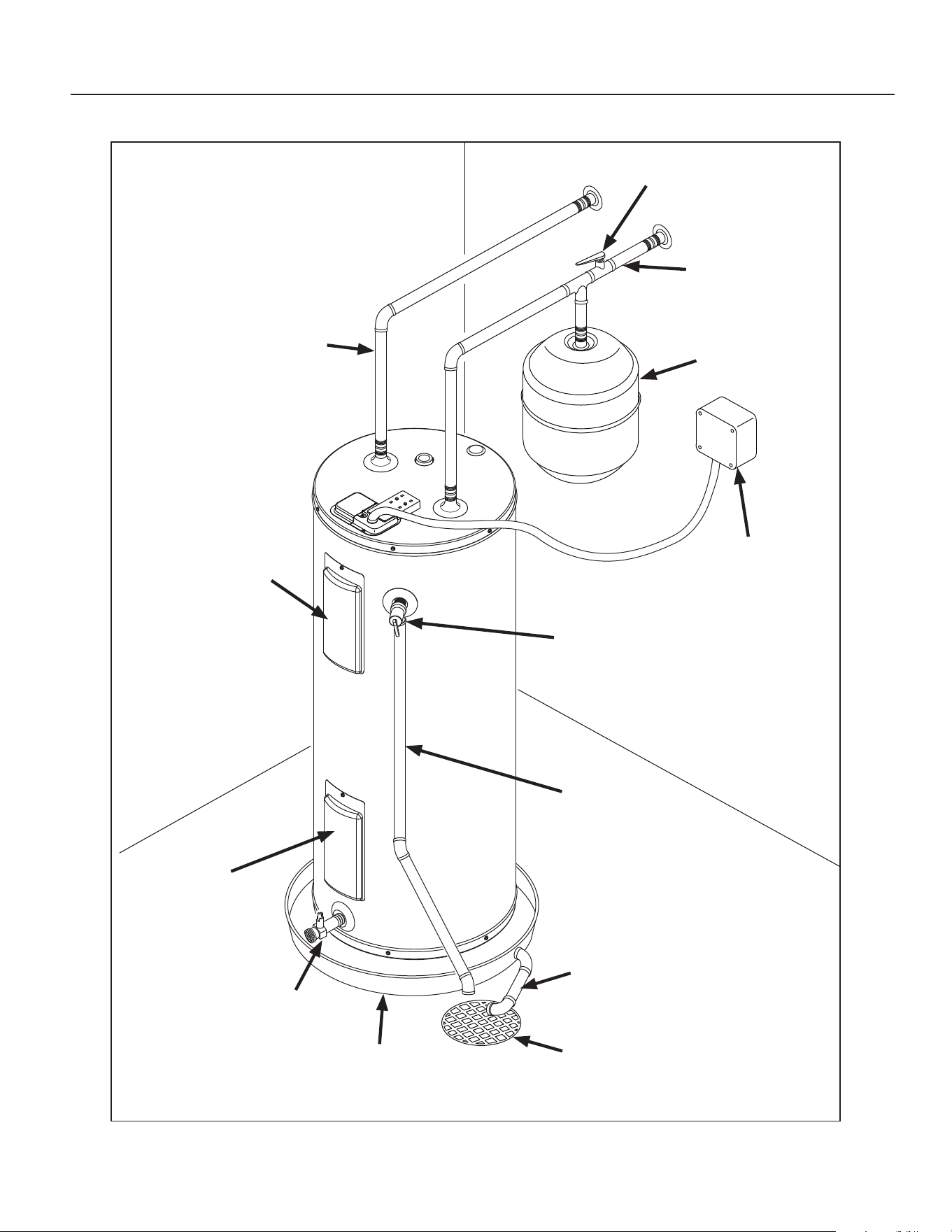
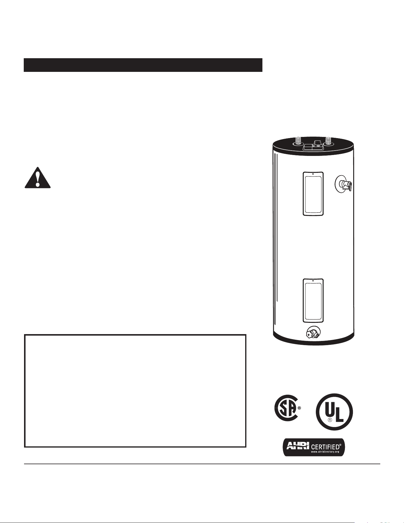
COMPLETED INSTALLATION (TYPICAL)
Electronic Thermostat
and Upper Element
access
Lower
Element and
Thermostat
access
T&P
relief
valve
Water
shut o
Electrical
juncon
box
T&P
discharge
pipe
Drain pan
discharge
pipe
Drain pan
Drain
valve
Expansion
tank
Cold
water
line
Hot
water
line
Drain
SAFETY
Residenal Electric Water Heater Use and Care Guide • 3
IMPORTANT SAFETY INFORMATION
Important informaon to keep
Fill out this secon and keep this
manual in the pocket of the water
heater for reference.
Date Puchased:
Model number:
Serial number:
Maintenance performed:* Date:
This is the safety alert symbol. It is used to alert you to
potenal physical injury hazards. Obey all safety mes-
sages that follow this symbol to avoid possible property
damage, serious injury or death. Do not remove any
permanent instrucons, labels, or the data plate from either the outside of
the water heater or on the inside of the access panels. Keep this manual
near the water heater.
DANGER
Read and follow all safety messages and instrucons in
this manual.
DANGER indicates hazardous
situaon that, if not avoided, will
result in death or serious injury.
WARNING
WARNING indicates a hazardous
situaon that, if not avoided, could
result in death or serious injury.
CAUTION
CAUTION indicates a hazardous
situaon that, if not avoided, could
result in minor or moderate injury.
NOTICE
NOTICE indicates pracces not
related to physical injury.
*Drain and ush tank and remove and
inspect anode rod aer rst six months
of operaon and at least annually
thereaer. Operate the Temperature
and Pressure Relief Valve (T&P) annu-
ally and inspect T&P valve every 2-4
years (see the label on the T&P valve
for maintenance schedule). If no label is
aached to the T&P Relief Valve, follow
the instrucons in the T&P Relief Valve
Maintenance secon of this manual.
See the Maintenance secon for more
informaon about maintaining this
water heater.
This product is certified to comply with a maximum weighted average of 0.25%
lead content as required in some areas.
4 • Residenal Electric Water Heater Use and Care Guide
IMPORTANT SAFETY INFORMATION
T
o reduce the risk of property
damage, serious injury or death,
read and follow the precauons below,
all labels on the water heater, and
the safety messages and instrucons
throughout this manual.
RISKS DURING INSTALLATION
AND MAINTENANCE
Electric Shock Risk
Contact with the electrical
parts in the junction box and
behind the access doors can
result in severe injury or death from
electrical shock:
• Disconnect power by open-
ing the circuit breaker or
removing the fuses before
installing or servicing.
• Use a non-contact circuit
tester to confirm that power
is off before working on or
near any electrical parts.
• Replace the junction box
cover and access doors after
servicing.
Liing Risk
WARNING! The
water heater is heavy.
Follow these precau-
ons to reduce the
risk of property damage, injuries from
liing or impact injuries from dropping
the water heater.
• Use at least two people to li the
water heater.
• Be sure you both have a good grip
before liing.
• Use an appliance dolly or hand
truck to move the water heater.
RISKS DURING OPERATION
Scalding Risk
This water heater
can make water hot
enough to cause
severe burns instantly, resulting in
severe injury or death.
Feel water before bathing or shower-
ing. To reduce the risk of scalding,
install Thermostatic Mixing Valves
(temperature limiting valves) at each
point-of-use. These valves automati-
cally mix hot and cold water to limit
the temperature at the tap. Mixing
valves are available from local hard-
ware stores. Follow manufacturer’s
instructions for installation and
adjustment of the valves.
The thermostat(s) on this water
heater have been factory set to
approximately 120°F to reduce the
risk of scalding. Higher temperatures
increase the risk of scalding, but
even at 120°F, hot water can scald.
If you choose a higher temperature,
Thermostatic Mixing Valves located
at each point-of-use are particularly
important to help avoid scalding.
For informaon about changing the
factory thermostat seng(s), refer to
the “Adjusng Temperature” secon in
this manual (“Step 10” on page 15).
Even if you set the water heater
thermostat(s) to a low seng, higher
temperatures may occur in certain
circumstances:
In some cases, repeated small draws of
water can cause the hot and cold water
in the tank to “stack” in layers. If this
happens, the water can be as much as
thirty degrees hoer than the thermo-
stat seng. This temperature variaon
is the result of your usage paern and
is not a malfuncon.
Water temperature will be hoer if
someone adjusted the thermostat(s) to
a higher seng.
Problems with the thermostat(s),
or other malfuncons may result in
higher than expected water tempera-
tures.
If the water heater is in a hot envi-
ronment, the water in the tank can
become as hot as the surrounding air,
regardless of the thermostat seng.
If the water supplied to the water
heater is pre-heated (for example, by
a solar system) the temperature in the
tank may be higher than the water
heater’s thermostat seng.
To reduce the risk of unusually hot wa-
ter reaching the xtures in the house,
install Thermostac Mixing Valves at
each point-of-use.
If anyone in your home is at parcular
risk of scalding (for example, the elder-
ly, children, or people with disabilies)
or if there is a local code or state law
requiring a certain water temperature
Temperature Time to Produce
a Serious Burn
120°F (49°C) More than 5 minutes
125°F (52°C) 1½ to 2 minutes
130°F (54°C) About 30 seconds
135°F (57°C) About 10 seconds
140°F (60°C) Less than 5 seconds
145°F (63°C) Less than 3 seconds
150°F (66°C) About 1½ seconds
155°F (68°C) About 1 second
SAFETY
Residenal Electric Water Heater Use and Care Guide • 5
at the hot water tap, then these precau-
ons are parcularly important.
According to a naonal standard
American Society of Sanary Engineer-
ing (ASSE 1070) and most local plumbing
codes, the water heater’s thermostat
should not be used as the sole means to
regulate water temperature and avoid
scalds.
Properly adjusted Thermostac Mixing
Valves installed at each point-of-use al-
low you to set the tank temperature to
a higher seng without increasing risk
of scalds. A higher temperature seng
allows the tank to provide much more
hot water and can help provide proper
water temperatures for appliances such
as dishwashers and washing machines.
Higher tank temperatures (140°F)
also kill bacteria that cause a condi-
on known as “smelly water” and can
reduce the levels of bacteria that cause
water-borne diseases.
Water Contaminaon Risk
Do not use chemicals that could con-
taminate the potable water supply. Do
not use piping that has been treated
with chromates, boiler seal, or other
chemicals.
Fire Risk
To reduce the risk of a
fire that could destroy
your home and serious-
ly injure or kill people:
• Do not store things that can burn
easily such as paper or clothes next
to the water heater.
• Be sure the junction box cover and
the access door covers are in place.
These covers keep debris from enter-
ing and potentially being ignited,
and help keep any internal fires from
spreading.
• Keep the water heater from becom-
ing wet. Immediately shut the water
heater off and have it inspected by a
qualified person if you find that the
wiring, thermostat(s) or surround-
ing insulation have been exposed to
water in any way (e.g., leaks from
plumbing, leaks from the water heat-
er itself can damage property and
could cause a fire risk). If the water
heater is subjected to flood condi-
tions or the thermostat(s) have been
submerged in water, the entire water
heater must be replaced.
• Make electrical connections proprly,
according to the instructions on page
14. Use 10 gauge solid copper wire.
Use a UL listed or CSA approved
strain relief. Connect ground wire to
green ground screw.
Explosion Risk
High temperatures and
pressures in the water
heater tank can cause an
explosion resulng in property
damage, serious injury or death. A
new Temperature and Pressure (T&P)
Relief Valve is included with your water
heater to reduce risk of explosion by
discharging hot water. Addional
temperature and pressure protecve
equipment may be required by local
codes.
A naonally recognized tesng labora-
tory maintains periodic inspecon of
the valve producon process and cer-
es that it meets the requirements
for Relief Valves for Hot Water Supply
Systems, ANSI Z21.22. The T&P Relief
Valve’s relief pressure must not exceed
the working pressure rang of the wa-
ter heater as stated on the rang plate.
Maintain the T&P Relief Valve prop-
erly. Follow the maintenance instruc-
tions provided by the manufacturer of
the T&P Relief Valve (label attached
to T&P Relief Valve). If no label is
attached to the T&P Relief Valve, fol-
low the instructions in the T&P Relief
Valve Maintenance section of this
manual.
An explosion could occur if the T&P
Relief Valve or discharge pipe is
blocked. Do not cap or plug the T&P
Relief Valve or discharge pipe.
Fire and Explosion Risk if Hot Water is
Not Used for Two Weeks or More
CAUTION! Hydrogen gas builds up in
a hot water system when it is not used
for a long period (two weeks or more).
Hydrogen gas is extremely ammable.
If the hot water system has not been
used for two weeks or more, open a
hot water faucet for several minutes at
the kitchen sink before using any elec-
trical appliances connected to the hot
water system. Do not smoke or have
an open ame or other ignion source
near the faucet while it is open.
SAFETY
6 • Residenal Electric Water Heater Use and Care Guide
GETTING STARTED
GETTING STARTED
1
Review all of the instrucons
before you begin work.
If you aren’t sure that you
can safely and properly do this work
yourself, call your local hardware store
to arrange for Professional Installaon
(you may also call a qualied person
of your choice, such as a licensed
plumber or electrician, to have the
work done). Improper installaon can
damage the water heater, your home
and other property, and can present
risks of serious injury or death.
2
Check with your local and
state authories for any local
or state codes that apply to
your area. In the absence of local and
state codes, follow Naonal Fire
Protecon Associaon (NFPA-70) and
the current edions of the Naonal
Electric Code (NEC) and the Interna-
onal Plumbing Code (IPC). The
instrucons in this manual comply with
naonal codes, but the installer is
responsible for complying with local
codes.
Massachuses code requires this wa-
ter heater to be installed in accordance
with Massachuses 248-CMR 2.00 and
248-CMR 5.00: State Plumbing Code.
Other local and state authories may
have similar requirements or other
codes applicable to the installaon of
this water heater.
3
Before you start, be sure you
have, and know how to use, the
following tools and supplies:
• Plumbing tools and supplies appropriate
for the type of water pipes in your home
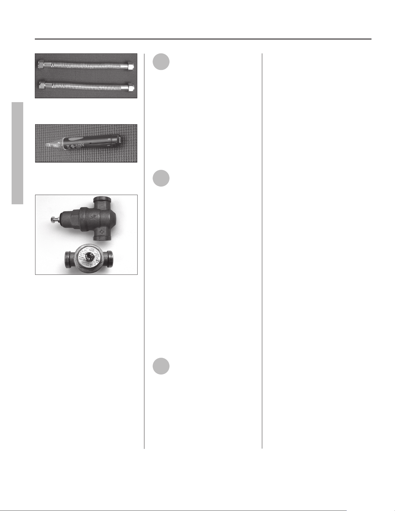
• Threaded connectors (gure 1) for
the cold and hot water pipes
• For homes plumbed with plasc
pipe, use threaded connectors
suitable for the specic type of
plasc pipe used: CPVC and PEX
(cross-linked polyethylene). Do
not use PVC pipe.
• For homes with copper pipes,
you may purchase connector kits
with compression ngs that
don’t require soldering (gure 1).
Compression ngs are easier
to install than soldering copper
pipes.
• Thread sealant tape or pipe joint
compound approved for potable
water
• Tools to make the electrical connec-
ons (for example, screwdrivers, wire
strippers)
• Non-Contact circuit tester to check
for power (gure 2)
• Water Pressure Gauge (see next
page, gure 4)
Recommended Accessories:
• Suitable drain pan (see page 8, gure 6)
• Automac leak detecon and shut-
o device
• Pressure Reducing Valve (gure 3)
• Thermal Expansion Tank (see next
page, gure 5)
• Point-of-use Thermostac Mixing
Valves (see page 8, gure 7) ■
Figure 1 - Flexible connectors use compression
ngs and do not require soldering.
Figure 2 - Use a non-contact circuit tester to
insure that the power is o before you work on
a circuit.
Figure 3 - Install a Pressure Reducing Valve set to
50 to 60 PSI.
Residenal Electric Water Heater Use and Care Guide • 7
INSTALLATION
F
ollow these steps for proper
installaon:
✓
Verify that your
home is equipped
and up-to-date for
proper operaon
Installing a new water heater is the
perfect me to examine your home’s
plumbing system and make sure the
system is up to current code standards.
There have likely been plumbing code
changes since the old water heater was
installed. We recommend installing the
following accessories and any other
needed changes to bring your home up
to the latest code requirements.
Use the checklist below and inspect
your home. Install any devices you need
to comply with codes and assure that
your new water heater performs at its
best. Check with your local plumbing
ocial for more informaon.
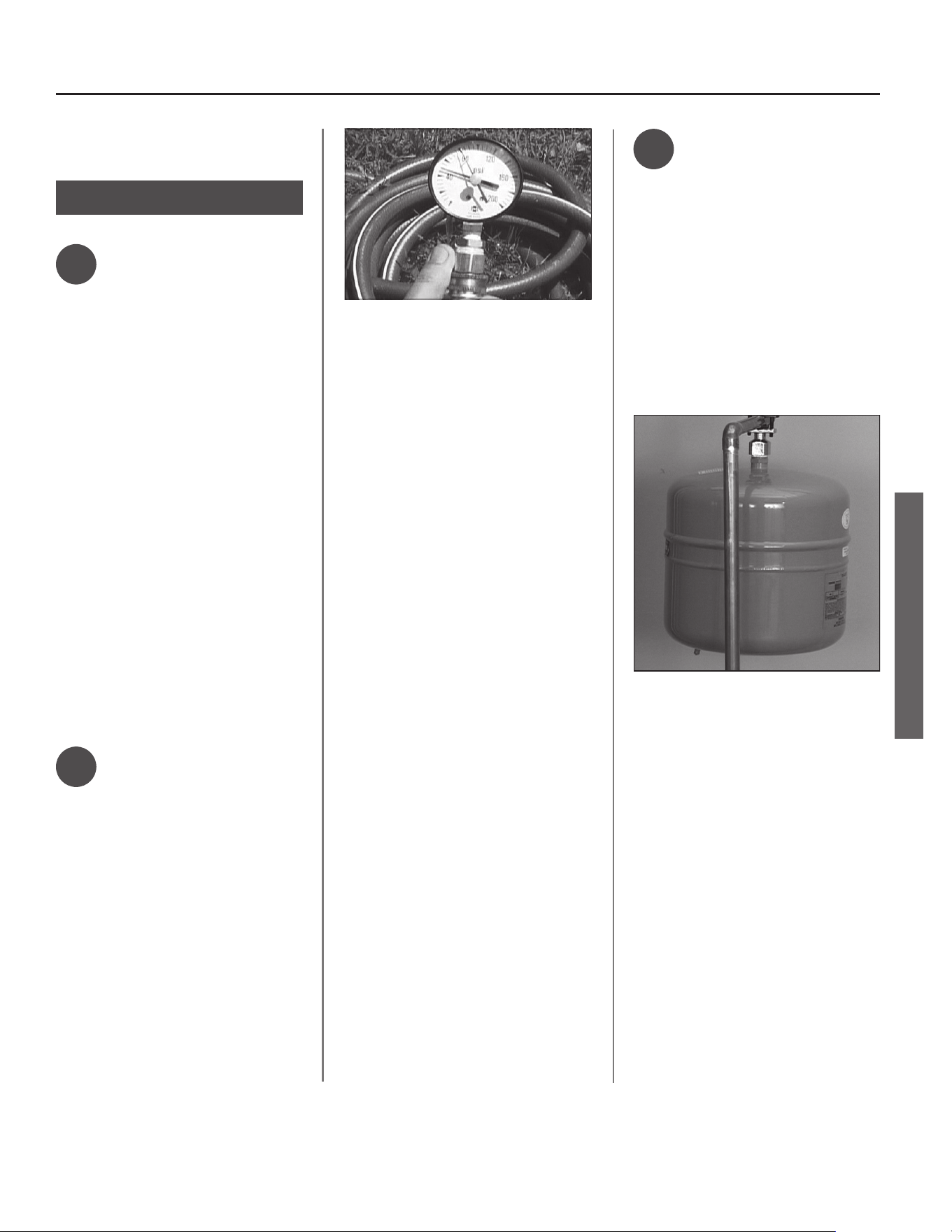
✓
Water pressure
We recommend checking your
home’s water pressure with a pressure
gauge (gure 4). Most codes allow a
maximum incoming water pressure of
80 psi. We recommend a working pres-
sure no higher than 50-60 psi.
HOW: Purchase an inexpensive water
pressure gauge available at your local
hardware store. Connect the Water
Pressure Gauge to an outside faucet
and measure the maximum water
pressure experienced throughout the
day (highest water pressures oen oc-
cur at night).
To limit your home’s water pressure:
Locate your home’s Pressure Reduc-
ing Valve (PRV) on the main incoming
(cold) water supply line and adjust the
water pressure control to between 50
and 60 psi. If your home does not have
a Pressure Reducing Valve, install a
PRV on the home’s main water supply
line and set it to between 50 and 60
psi. Pressure Reducing Valves are avail-
able at local hardware store.
BACKGROUND: Over the years, many
ulies have increased water sup-
ply pressures so they can serve more
homes. In some homes today, pres-
sures exceed 100 psi. High water
pressures can damage water heaters,
causing premature leaks. If you have
replaced toilet valves, had a water
heater leak, or had to repair applianc-
es connected to the plumbing system,
pay parcular aenon to your home’s
water pressure. When purshasing a
PRV, make sure the PRV has a built-in
bypass.
✓
Water pressure
increase caused by
thermal expansion
Verify that you have a properly sized
Thermal Expansion Tank (gure 5). We
recommend installing an expansion
tank if your home does not have one.
Codes require a properly pressurized,
properly sized Thermal Expansion Tank
in almost all homes. (See photo on
inside front cover.)
HOW: Connect the Thermal Expansion
Tank (available at your local hardware
store) to the cold water supply line
near the water heater. The expansion
tank contains a bladder and an air
charge. To work properly, the Thermal
Expansion Tank must be sized accord-
ing to the water heater’s tank capacity
and pressurized to match the home’s
incoming water pressure. Refer to the
installaon instrucons provided with
the Thermal Expansion Tank for instal-
laon details.
Figure 4 - Use a Water Pressure Gauge to make
sure your home’s water pressure is not too high.
Figure 5 - A Thermal Expansion Tank helps
protect the home’s plumbing system from pres-
sure spikes.
Step 1:
INSTALLATION
8 • Residenal Electric Water Heater Use and Care Guide
INSTALLATION
BACKGROUND: Water expands when
heated, and the increased volume
of water must have a place to go, or
thermal expansion will cause large
increases in water pressure (despite
the use of a Pressure Reducing Valve
on the home’s main water supply
line). The Safe Drinking Water Act of
1974 requires the use of backow
preventers and check valves to restrict
water from your home reentering
the public water system. Backow
preventers are oen installed in water
meters and may not be readily visible.
As a result, most all plumbing systems
today are now “closed,” and almost all
homes now need a Thermal Expan-
sion Tank.
A Thermal Expansion Tank is a prac-
cal and inexpensive way to help avoid
damage to the water heater, washing
machine, dishwasher, ice maker and
even toilet valves. If your toilet oc-
casionally runs for no apparent reason
(usually briey at night), that may be
due to thermal expansion increasing
the water pressure temporarily.
Water pipe and tank
leaks
Leaks from plumbing pipes or from
the water heater itself can damage
property and could cause a re risk.
• Install an automac leak detecon and
shuto device (available in hardware
stores). These devices can detect
water leaks and can shut o the water
heater’s water supply if a leak occurs.
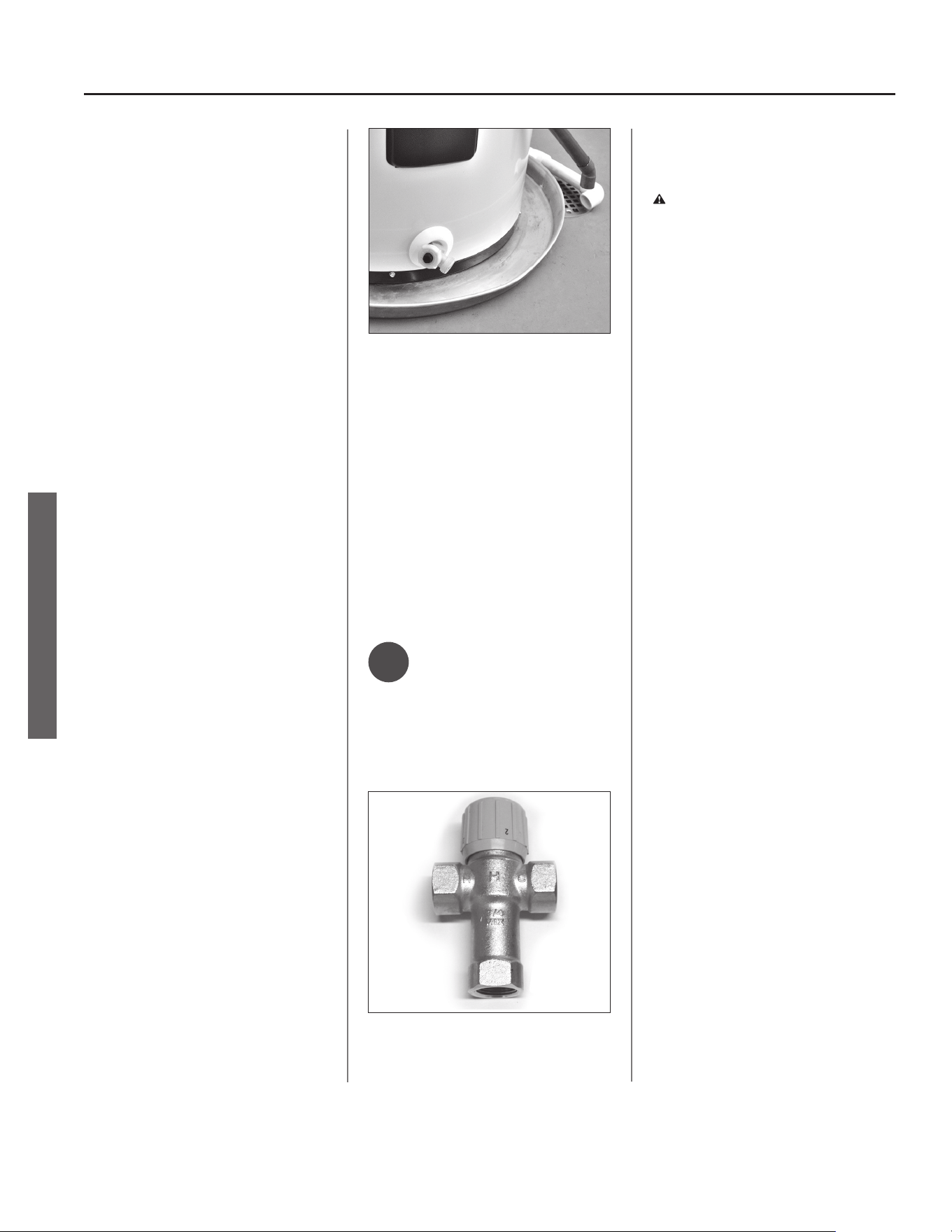
• Install a suitable drain pan (available
in stores) under the water heater
(gure 6) to catch condensaon or
leaks in the piping connecons or
tank. Most codes require and we
recommend installing the water
heater in a drain pan that is piped
to an adequate drain. The drain pan
must be at least two inches wider
than the diameter of the water
heater. Install the drain pan so the
water level would be limited to a
maximum depth of 1-3/4”.
✓
Water tempera-
ture regulaon
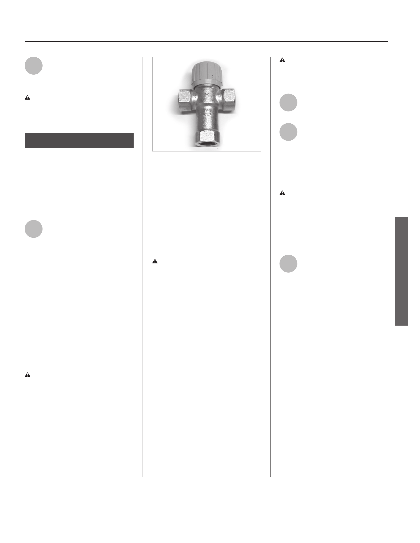
Install Thermostac Mixing Valves (g-
ure 7) to regulate the temperature of
the water supplied to each point-of-
use (for example, kitchen sink, bath-
room sink, bath, shower). Consult the
valve manufacturer’s instrucons or a
qualied person.
WARNING! Even if the water heater
thermostat is set to a relavely low
temperature, hot water can scald.
Install Thermostac Mixing Valves at
each point-of-use to reduce the risk of
scalding (see page 4).
BACKGROUND: A Thermostac Mix-
ing Valve, installed at each point-
of-use, mixes hot water from the
water heater with cold water to more
precisely regulate the temperature of
hot water supplied to xtures. If you
aren’t sure if your plumbing system
is equipped with properly installed
and adjusted Thermostac Mixing
Valves at each point where hot water
is used, contact a qualied person for
more informaon. ■
Figure 6 - A suitable drain pan piped to an
adequate drain can help protect ooring from
leaks and drips.
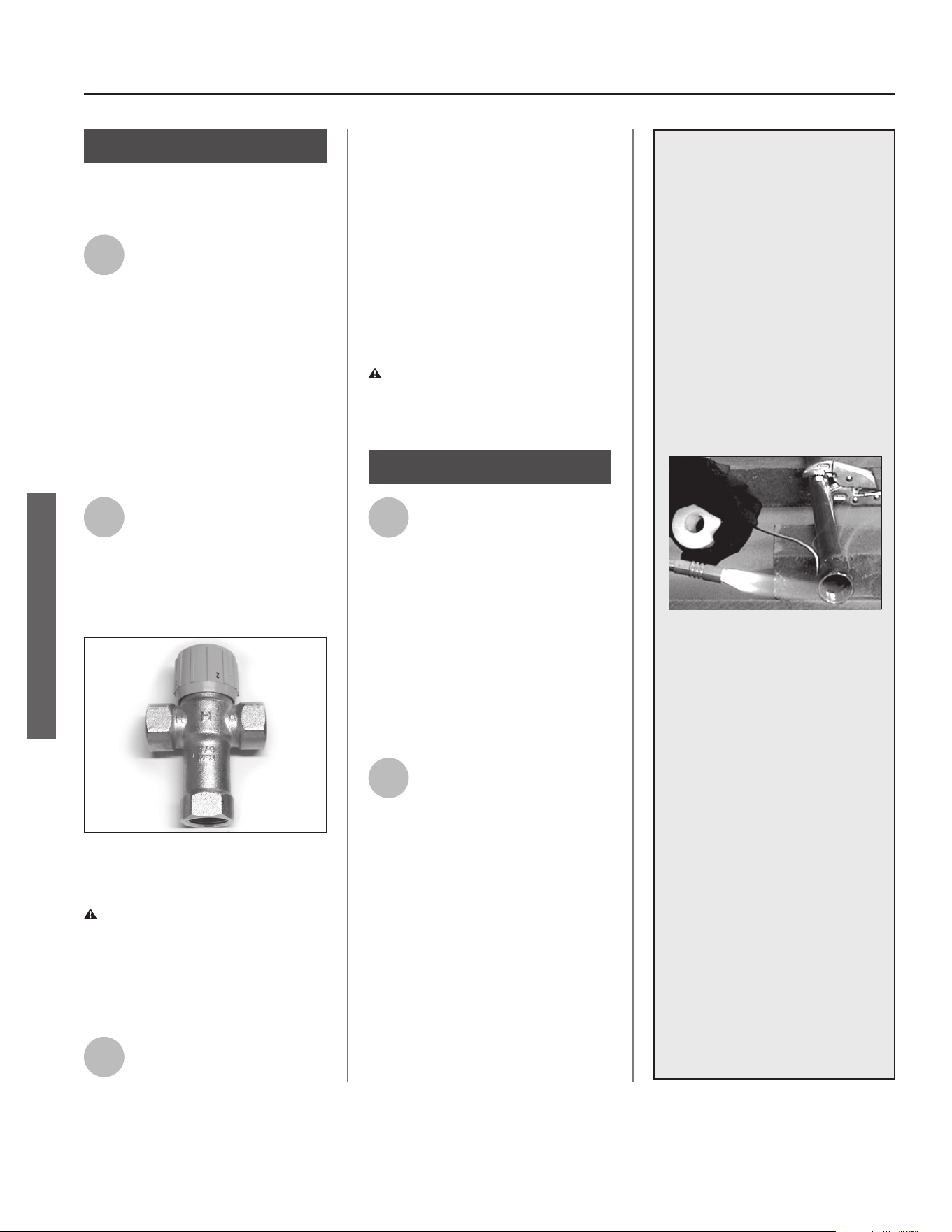
Figure 7 - Thermostac Mixing Valves installed
at each point-of-use can help prevent scalding.
INSTALLATION
Residenal Electric Water Heater Use and Care Guide • 9
Verify that the locaon
is appropriate
Before installing your water heater,
ensure that:
1
The water heater will be:
• Installed indoors close to
the center of the plumbing
system.
• In a suitable drain pan piped to an
adequate oor drain or external to
the building (See page 8, gure 6).
• In an area that will not freeze
• In an area that is suitable for install-
ing the water heater vercally
2
The locaon has adequate
space (clearances) for periodic
servicing.
3
The oor can support the
weight of a full water heater.
4
Your area is not prone to
earthquakes. If it is, use
special straps as required by
local building codes.
NOTICE: The state of California re-
quires bracing, anchoring, or strapping
the water heater to avoid its moving
during an earthquake. Contact local
ulies for code requirements in your
area, visit hp://www.dsa.dgs.ca.gov,
or call 1-916-445-8100 and request
instrucons. Other locaons may have
similar requirements. Check with your
local and state authories.
5
The locaon is not prone to
physical damage by vehicles,
ooding, or other risks.
6
Avoid locaons such as acs,
upper oors, or where a leak
might damage the structure
or furnishings. Due to the normal
corrosive acon of water, the tank will
eventually leak. To minimize property
damage from leaks, inspect and
maintain your water heater in accor-
dance with this manual’s instrucons.
Install a suitable drain pan under the
water heater piped to an adequate
drain. Inspect the drain pan, pipes, and
surrounding area regularly and x any
leaks found. Drain pans are available in
local hardware stores. Leaks are
frequently in the plumbing system
itself and not the water heater.
Removing the old water
heater
1
Read each installaon step
and decide if you have the
necessary skills to install the
water heater. Only proceed if you can
safely perform the work. If you are not
comfortable, have a qualied person
perform the installaon.
2
Locate the water heater’s
circuit breaker and turn it OFF
(or remove the circuit’s
fuses).
3
On the old water heater,
remove the electrical
junction box access panel.
Using a non-contact circuit tester,
check the wiring to make certain the
power is OFF.
WARNING! Working on an ener-
gized circuit can result in severe injury
or death from electrical shock.
4
Disconnect the electrical
wires.
5
Open a hot water faucet and
let the hot water run unl it is
cool (This may take 10
minutes or longer).
WARNING! Be sure the water runs
cool before draining the tank to reduce
the risk of scalding.
6
Connect a garden hose to the
drain valve and place the
other end of the hose in a
drain, outside, or a bucket. (Note that
sediment in the boom of the tank
may clog the valve and prevent it
from draining. If you can’t get the
Step 2:
Vehicle
Stop
Drain
Drain
Pan
In a garage, install a vehicle stop to avoid water
heater damage.
Step 3:
Let the hot water run unl it is cool.
INSTALLATION
10 • Residenal Electric Water Heater Use and Care Guide
INSTALLATION
tank to drain, contact a qualied
person.)
Turn the cold water supply
valve OFF.
8
Open the drain valve on the
water heater.
9
Also open a hot water faucet
to help the water in the tank
drain faster.
10
When the tank is empty,
disconnect the Temperature &
Pressure (T&P) Relief Valve
discharge pipe. You may be able to
reuse the discharge pipe, but do not
reuse the old T&P Relief Valve. A new
T&P Relief Valve comes installed on
your water heater (or on some models,
is in the carton with the water heater).
11
Disconnect the water pipes.
Many water pipes are
connected by a threaded
union which can be disconnected with
wrenches. If you must cut the water
pipes, cut the pipes close to the water
heater’s inlet and outlet connecons,
leaving the water pipes as long as
possible. If necessary, you can make
them shorter later when you install
the new water heater.
12
Remove the old water heater.
WARNING! Use two or more people
to remove or install water heater.
Failure to do so can result in back or
other injury.
Installing the new
water heater
1
Completely read all instruc-
ons before beginning. If you
are not sure you can com-
plete the installaon, DO NOT
RETURN THIS UNIT TO THE STORE.
Seek assistance from any of the
following sources:
• Professional Installaon is avail-
able for this product and the
work is guaranteed. Call your
local hardware store to have this
water heater installed.
• Schedule an appointment with
a qualied person to install your
water heater.
• Call our Technical Assistance Ho-
tline which is listed on the water
heater’s warranty sheet.
2
Install a suitable drain pan
that is piped to an adequate
drain.
3
Set the water heater in place
taking care not to damage
the drain pan.
NOTICE: Most codes require seng
the water heater in a suitable drain
pan piped to an adequate drain. The
drain pan helps avoid property dam-
age which may occur from condensa-
on or leaks in the piping connecons
or tank. The drain pan must be at
least two inches wider than the diam-
eter of the water heater. Install the
drain pan so the water level is limited
to a maximum depth of 1-3/4”.
4
Verify that the water heater
is set in place properly. Check
that:
• The T&P Relief Valve will not be in
contact with any electrical parts.
• There is adequate space to install
the T&P Relief Valve discharge pipe
and that it can be piped to a sepa-
rate drain (and not into the drain
pan).
• There is adequate access and space
around the water heater for future
maintenance.
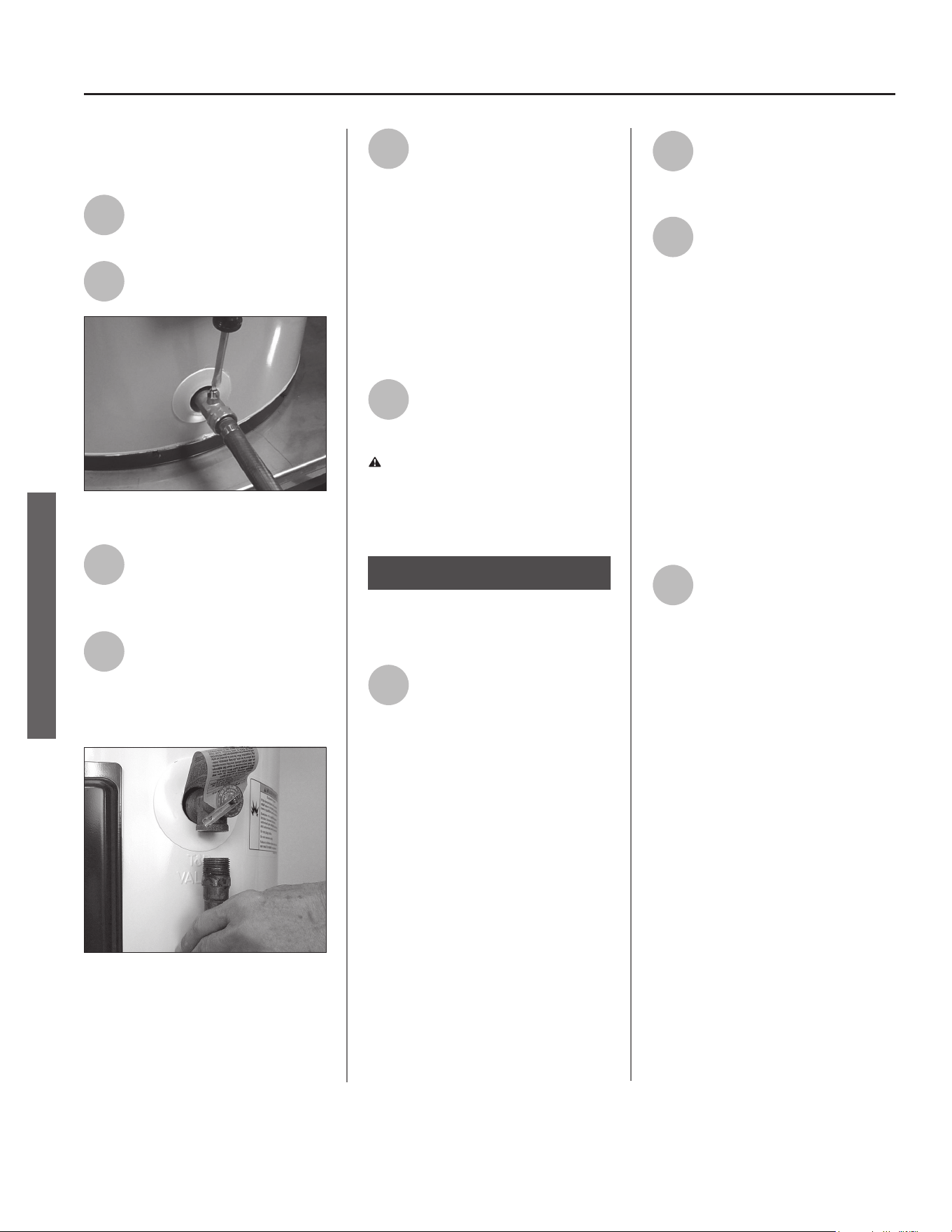
7
Draining the old water heater.
Removing the T&P Relief Valve discharge pipe.
Step 4:
INSTALLATION
DO NOT CONNECT ELECTRICAL
WIRING UNTIL YOU ARE
INSTRUCTED TO DO SO.
NOTICE: Connecng electrical power
to the tank before it is completely
full of water (water must run FULL
STREAM from a hot water tap for a full
three minutes) will cause the upper
heang element to burn out.
Connect the Tempera-
ture and Pressure (T&P)
Relief Valve/Pipe
Most T&P Relief Valves are pre-installed
at the factory. In some cases, they are
shipped in the carton and must be
installed in the opening marked and
provided for this purpose and according
to local codes.
WARNING! To avoid serious injury
or death from explosion, install a T&P
Relief Valve according to the following
instrucons:
1
If your water heater does not
have a factory installed T&P
Relief Valve, install the new
T&P Relief Valve that came with your
water heater. Do not reuse an old T&P
Relief Valve. Install a T&P Relief Valve
discharge pipe according to local codes
and the following guidelines:
• The discharge pipe should be at least
3/4” inside diameter and sloped for
proper drainage. Install it to allow
complete drainage of both the T&P
Relief Valve and the discharge pipe.
• The discharge pipe must withstand
250°F (121°C) without distoron. Use
only copper or CPVC pipe. Do not
use any other type of pipe, such as
PVC, iron, exible plasc pipe, or any
type of hose.
• Terminate the discharge pipe a maxi-
mum of six inches above a oor drain
or outside the building. Do not drain
the discharge pipe into the drain
pan; instead pipe it separately to
an adequate drain. In cold climates,
terminate the discharge pipe inside
the building to an adequate drain.
Outside drains could freeze and
obstruct the drain line. Protect the
drain from freezing.
• Do not place any valve or other re-
stricon between the tank and T&P
Relief Valve. Do not cap, block, plug,
or insert any valve between the T&P
Relief Valve and the end of the dis-
charge pipe. Do not insert or install
any reducer in the discharge pipe.
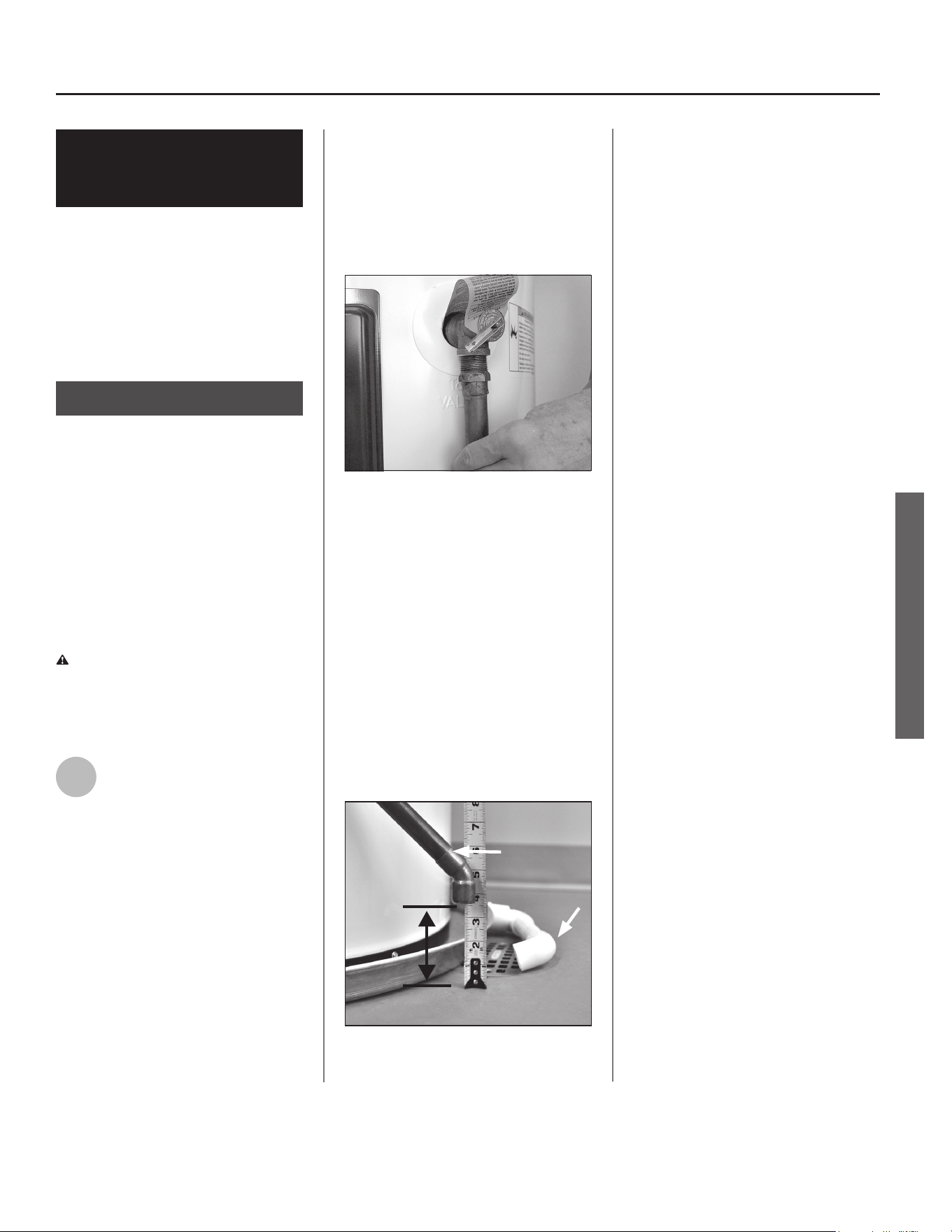
Residenal Electric Water Heater Use and Care Guide • 11
Step 5:
The T&P Relief Valve discharge pipe must be in-
stalled properly and piped to an adequate drain.
The end of the T&P Relief Valve discharge pipe
must stop no more than six inches above a oor
drain or outside.
DISCHARGE
PIPE
DRAIN
PIPE
INSTALLATION
Install shuto and
tempering valves
1
If one is not already installed,
install a manual shuto valve
in the cold water line that
supplies the water heater. Install the
shuto valve near the water heater so
that it is readily accessible. Only use
valves that are compable with
potable water. Use only full-ow ball
or gate valves. Other types of valves
may cause excessive restricon to the
water ow.
2
Install a Thermostac Mixing
Valve at each point-of-use
(for example, kitchen sink,
bathroom sink, bath, shower).
Consult the valve manufacturer’s
instrucons or a qualied person.
WARNING! Even if the water
heater’s thermostat(s) are set to a
relavely low temperature, hot water
can scald. Install Thermostac Mixing
Valves at each point-of-use to reduce
the risk of scalding. (See page 4.)
3
For water heaters that are fed
by a solar water heang system (or
any other pre-heang system), always
install a Thermostac Mixing Valve or
other temperature liming device in
the inlet water supply line to limit
water supply inlet temperature to
120°F. Solar water heang systems can
supply water with temperatures
exceeding 170°F and may result in
water heater malfuncon.
WARNING! Hot water provided by
solar heang systems can cause
severe burns instantly, resulng in
severe injury or death (see page 4).
1
Connect the water
supply
Determine the type of water pipes in
your home. Most homes use copper
water pipes, but some use CPVC or
cross-linked polyethylene (PEX). Use
ngs appropriate for the type of pipe
in your home. Do not use iron or PVC
pipe – they are not suitable for potable
water.
2
Connect the cold water
supply using 3/4 inch
Naonal Pipe Thread “NPT”
to the ng marked “C” (COLD).
For ease of removing the water heater
for service or replacement, connect
the water pipes with a coupling called
a union. We recommend using a
dielectric-type union (available at lo-
cal hardware stores). Dielectric unions
can help prevent corrosion caused by
ny electric currents common in cop-
per water pipes and can help extend
the life of the water heater.
12 • Residenal Electric Water Heater Use and Care Guide
INSTALLATION
Step 6:
Install Thermostac Mixing Valves at each point
where hot water will be used.
Step 7:
IF YOU HAVE COPPER
PIPES:
If your home has copper water
pipes, you can solder the water
pipe connecons or use compres-
sion ngs which don’t require
soldering. Compression ngs
are easier to install than soldering
pipe. Check with local plumbing
ocials to determine what types
of pipe materials are suitable for
your locaon. Do not use lead-
based solder.
NOTICE: Do not solder pipes while
they are aached to the water
heater. The water heater’s inlet
and outlet connecons contain
non-metallic parts which could be
damaged. The proper way to con-
nect the water heater to copper
water pipes is as follows:
• Solder a short length of pipe
(about a foot or so) to a threaded
adapter using only 95/5 n-
anmony or equivalent solder.
Aach the threaded adapters to
the water heater’s connecons
(using thread sealant tape or pipe
joint compound). Connect the
home’s water pipes by soldering,
keeping the connecons at the
water heater cool with wet rags.
INSTALLATION
Residenal Electric Water Heater Use and Care Guide • 13
NOTICE: Most water heater models
contain energy saving heat traps in the
inlet and outlet connecons to avoid
the circulaon of hot water within the
pipes. Do not remove the heat traps.
3
Connect the hot water supply
using 3/4 inch NPT to the
ng marked “H” (HOT).
Follow the same connecon guidelines
as for the cold water supply.
4
Install insulaon (or heat
tape) on the water pipes
especially if the indoor
installaon area is subject to freezing
temperatures. Insulang the hot water
pipes can increase energy eciency.
5
Double check to make sure
the hot and cold water pipes
are connected to the correct
hot and cold water ngs on the
water heater.
6
If needed, install (or adjust)
the home’s Pressure Reducing
Valve to 50-60 psi and install a
Thermal Expansion Tank.
Verify connecons and
completely ll tank
To remove air from the tank and allow
the tank to ll completely with water,
follow these steps:
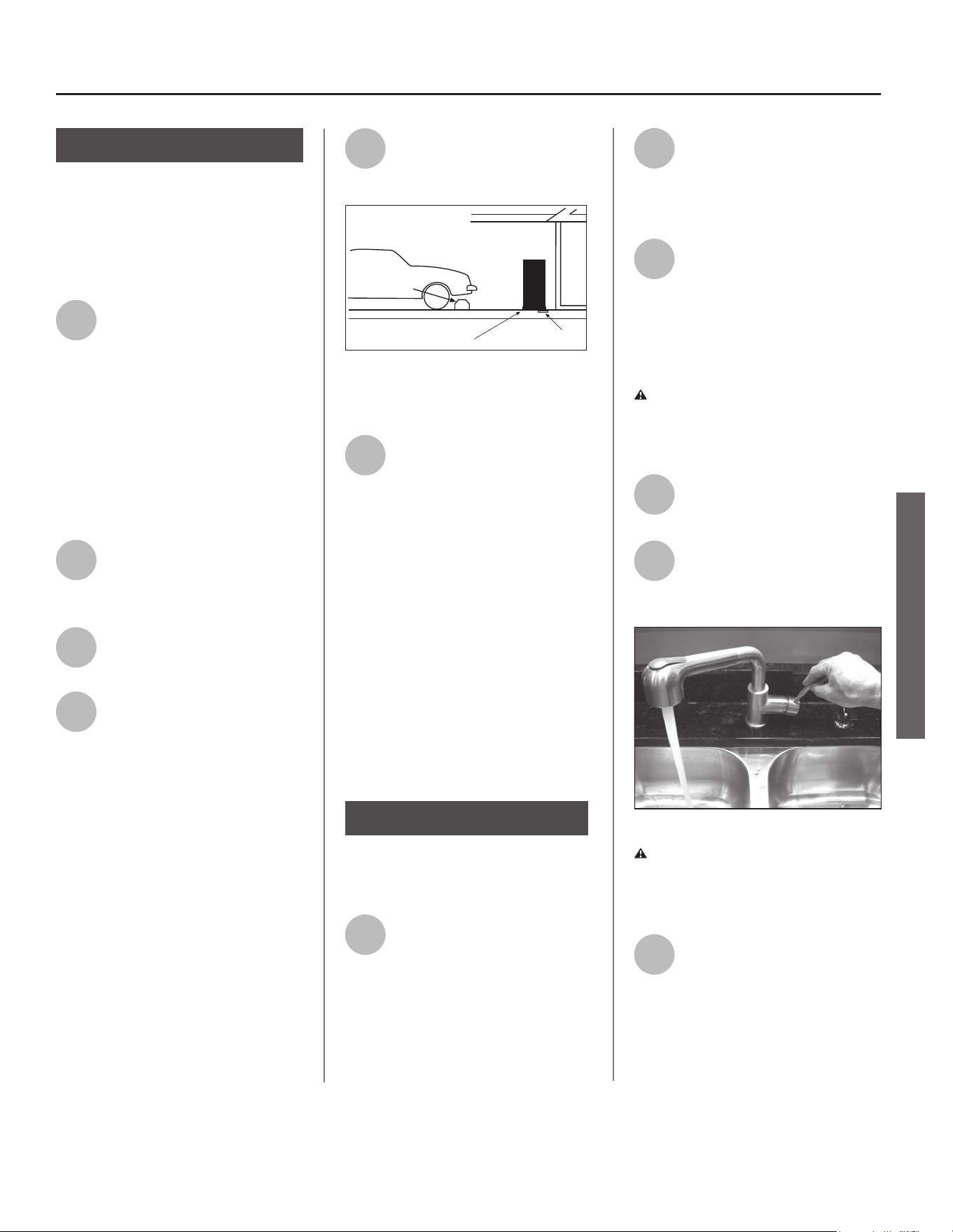
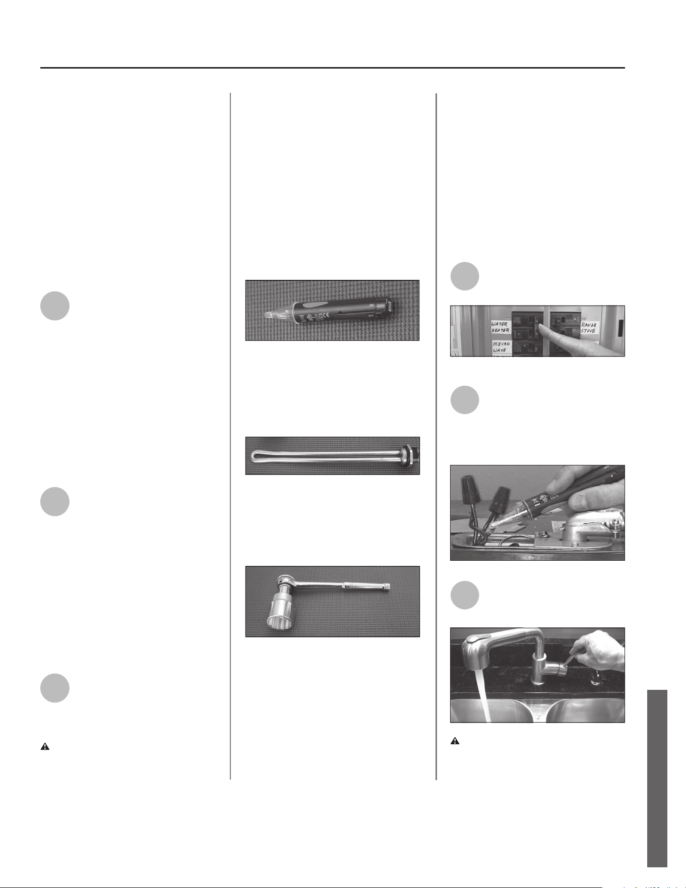
1
Remove the aerator at the
nearest hot water faucet. This
allows any debris in the tank
or plumbing system to be washed out.
2
Turn the cold water supply
back on.
3
Open a hot water faucet and
allow the water to run unl it
ows with a full stream.
4
Let the water run full stream
for three full minutes.
5
Close the hot water faucet
and replace the aerator.
6
Check inlet and outlet
connecons and water pipes
for leaks. Dry all pipes so that
any drips or leaks will be apparent.
Repair any leaks. Almost all leaks occur
at connecons and are not a tank leak.
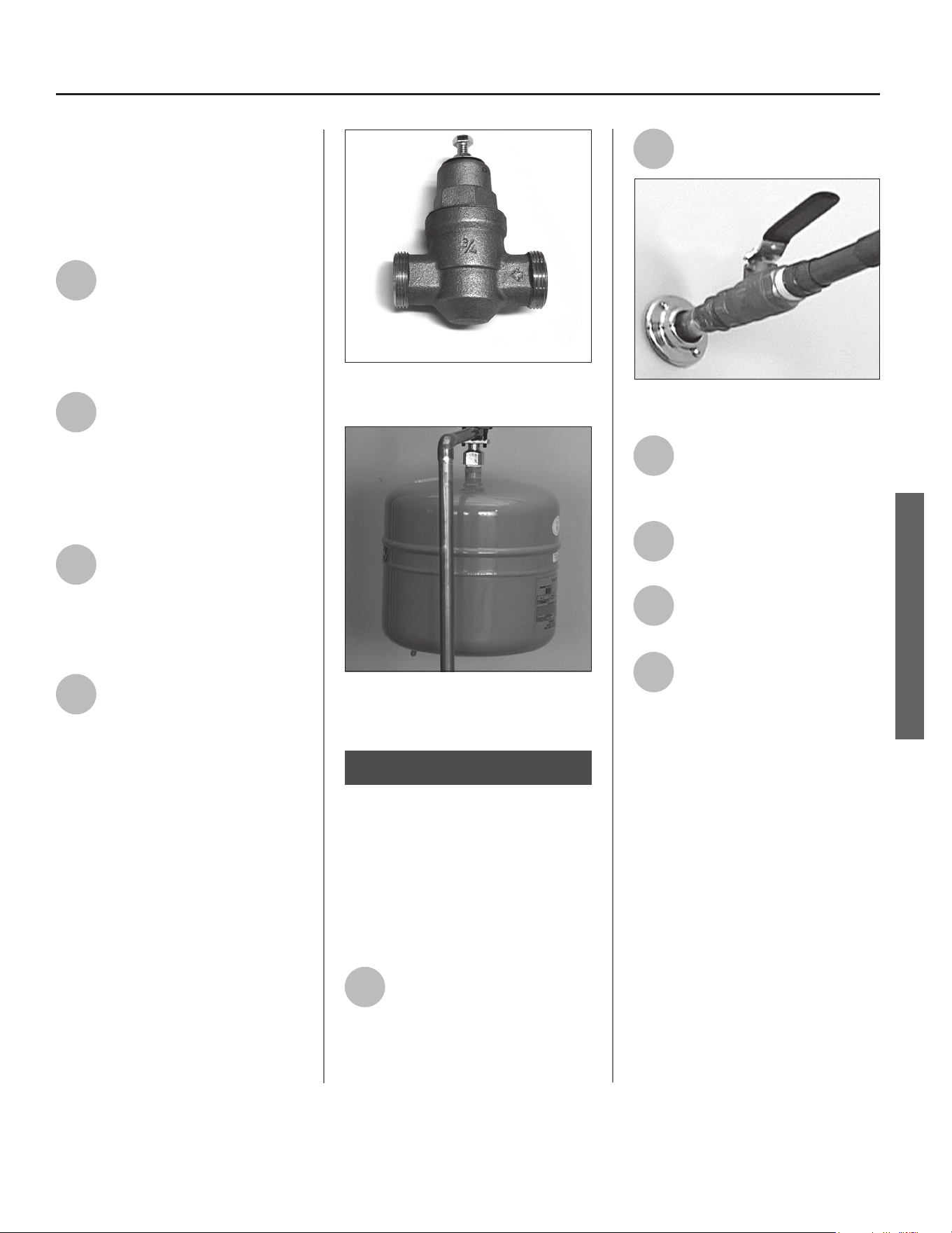
Full-ow ball valve
A Pressure Reducing Valve is required if your
home’s water pressure is above 80 psi.
The Thermal Expansion Tank should be pres-
surized with air, to match the home’s incoming
water pressure.
Step 8:
Fully open the cold water supply valve.
INSTALLATION
14 • Residenal Electric Water Heater Use and Care Guide
INSTALLATION
Make electrical
connecons
WARNING! Working on an ener-
gized circuit can result in severe injury
or death from electrical shock.
NOTICE: Do not turn electrical power
on unless you are sure all of the air
is out of the tank and the tank is
completely full of water. If power is
applied before the tank is completely
full of water, the upper element will
burn out (Dry Fire).
1
Be sure the electrical power
to the water heater is turned
OFF at the circuit breaker
panel (or remove the circuit’s fuses).
2
Using a non-contact circuit
tester, check the wiring to
make certain the power is OFF.
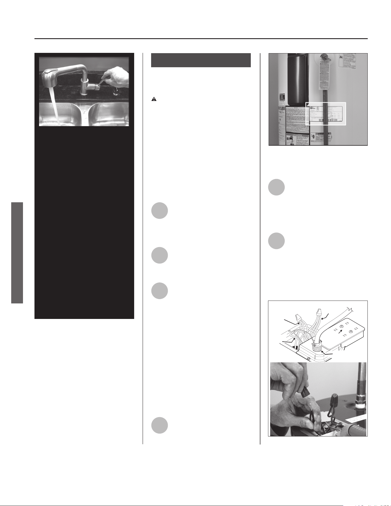
3
Check the water heater’s
data plate and ensure that
the home’s voltage, wiring
size (ampacity) and circuit breaker
rang and type are correct for this
water heater. Refer to the wiring
diagram located on the water heater
for the correct electrical connecons.
Ensure that wire sizes, type, and
connecons comply with all appli-
cable local codes. In the absence of
local codes, follow NFPA-70 and the
current edion of the Naonal Electric
Code (NEC).
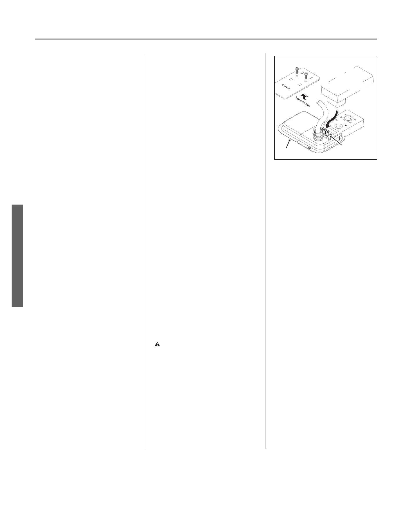
4
Remove the cover on the
electrical juncon box on the
top of the water heater.
5
Install wiring in an approved
conduit (if required by local
codes). Use a UL listed or CSA
approved strain relief to secure the
electrical wiring to the water heater.
6
Connect the ground wire to
the green ground screw.
Connect the home’s two
power wires to the water heater’s
four power wires (black to black, red
to red). Use suitable wire nuts or
other approved means to make the
power connecons.
NOTICE: The tank must be com-
pletely empty of air and full of
water before connecng electrical
power to avoid “Dry Firing.” Dry
Firing may result in the upper ele-
ment burning out. This is a com-
mon installaon mistake. Aer
you make the water connecons,
but before you connect the electri-
cal power, open a hot water faucet
and let the water run full unl all
the air is removed. Let the “hot”
water run full for three minutes
or longer before connecng any
electrical wires. A Dry Fired upper
heang element is an installaon
error and is not covered under
warranty.
If Dry Firing occurs, replace the up-
per heang element according to
the instrucons on page 26.
Step 9:
The water heater’s electrical requirements can
be determined from the data plate.
Red Wires
(3)
Smart Grid
Cover
1/2” Conduit
Connection
Black Wires
(3)
Ground
Wires
Connecng the electrical wires.
INSTALLATION
Residenal Electric Water Heater Use and Care Guide • 15
Replace the juncon box
cover and secure with the
screws provided.
WARNING! Be sure cover is secured
to reduce the risk of re and electric
shock.
Adjusng the
Temperature
With the installaon steps completed,
you may adjust the water heater’s
temperature seng if desired.
1
Set the thermostat(s) to
desired temperature. The
thermostat(s) on this water
heater have been factory set to
approximately 120°F to reduce the risk
of scald injury. You may wish to set a
higher temperature to provide hot
water for automac dishwashers or
laundry machines, to provide more hot
water capacity, and to reduce bacterial
growth. Higher tank temperatures
(140° F) kill bacteria that cause a
condion known as “smelly water”
and can reduce the levels of bacteria
that cause water-borne diseases.
WARNING! Higher temperatures
increase the risk of scalding, but even at
120°F, hot water can scald (see page 4).
If you increase the water heater’s tem-
perature seng, install Thermostac
Mixing Valve(s) at each point-of-use to
reduce the risk of scalding.
To adjust the water heater’s thermo-
stat:
• Be sure the electrical power to the
water heater is turned OFF at the
circuit breaker panel (or remove the
circuit’s fuses).
WARNING! Working near an
energized circuit can result in severe
injury or death from electrical shock.
Check wires with a circuit tester to
make sure power is o.
• Remove the upper and lower access
panels and fold away the insulaon.
• Turn the water temperature dial
clockwise ( >>) to increase the tem-
perature, or counter clockwise ( << )
to decrease the temperature. Adjust
thermostat to the desire tempera-
ture set-point.
NOTE: Your water heater has only one
thermostat, it is located behind the
upper access panel.
• Fold the insulaon back in place and
replace the access panels.
WARNING! Be sure panels are
secured to reduce the risk of re and
electric shock.
2
Turn the electric power back
on.
3
Wait for the water to heat up.
It may take several hours for a
tank of cold water to heat up.
If you have no hot water aer two
hours, refer to the Troubleshoong
Secon (see page 21).
WARNING! If you have increased
the temperature seng and the
Thermostac Mixing Valves are not set
properly (or not installed) you could
scald yourself while checking the
temperature.
4
Check water temperature at
several points of use in your
home (for example, bathtub
faucet, shower, or lavatory sink) and
adjust the Thermostac Mixing Valves
as needed. If you aren’t sure how to
adjust the Thermostac Mixing Valve
sengs, or aren’t sure if you have
Thermostac Mixing Valves, contact a
qualied person.
Step 10:
7
Adjust Thermostac Mixing Valves at each point-
of-use to 120°F or lower.
INSTALLATION
16 • Residenal Electric Water Heater Use and Care Guide
INSTALLATION
Operaon
The water heater is now ready for
normal operaon. To keep your water
heater working safely and eciently
and extend its life, perform mainte-
nance according to the schedule on
page 25.
Vacaon
To save energy, lower the temperature
seng on the thermostat(s) if you
plan to be gone for an extended me.
Follow the instrucons in Step 10 for
adjusng the thermostat to a lower
temperature seng before you leave
and to properly raise the temperature
seng when you return.
CAUTION! Hydrogen gas builds up
in a hot water system when it is not
used for a long period (two weeks
or more). Hydrogen gas is extremely
ammable. If the hot water system
has not been used for two weeks or
more, open a hot water faucet for
several minutes at the kitchen sink
before using any electrical appliances
connected to the hot water system.
Do not smoke or have an open ame
or other ignion source near the fau-
cet while it is open.
Step 11:
INSTALLATION
Need Assistance?
Call our Technical Assistance Hotline which is listed on the water
heater’s warranty sheet.
We can help you with installaon, operaon, troubleshoong, or maintenance.
Before you call, write down the model and serial number from the
water heater’s data plate.
Residenal Electric Water Heater Use and Care Guide • 17
INSTALLATION
INSTALLATION
The Electronic Thermostat
IMPORTANT: The Grid Communica-
on Adaptor must be removed before
aempng to access the thermostat.
NOTE: for the Electronic Thermostat
(ET) changes to remain in eect the Grid
Communicaon Adaptor must not be
reconnected, also read the “Risks During
Operaon” under the “Important Safety
Informaon” secon. If the instrucons
are not clear, contact a qualied service
technician.
Water Temperature Adjustment
The Grid Communicaon Adaptor is in-
tended to serve as the primary interface
for operang the water heater; however,
the Electronic Thermostat (ET) may
control the water heater in the absence
of the Grid Communicaon Adaptor.
The Electronic Thermostat consists of
an electronics box that contains a low
voltage power supply, the thermostat
set point knob, relays to switch between
the upper and lower heang elements,
one control thermistor, a connector for
the lower element control thermistor,
microelectronics to convert the thermis-
tor signals and perform switching and
other logic funcons, and a connector to
e the Electronic Thermostat (ET) to the
Grid Communicaon Adaptor located on
the top of the water heater. The majority
of the self-diagnoscs are located in the
Electronic Thermostat (ET), including the
dry-re protecon intelligence. The ther-
mostat circuit is designed so that when
the upper heang element calls for heat,
the power is directed to that element
even if the lower element is also calling
for heat.
Diagnosc LED Light
The Green/Red LED light indicates the
status of the electronic thermostat (See
Figure 8).
• Green LED will signal normal opera-
on. The green LED will blink 2 mes
per second to indicate that power is ap-
plied to the upper heang element and
at a faster rate (4 mes per second) to
indicate that the lower heang element
is powered.
• Red LED will ash error codes. If
a fault is detected by the electronic
thermostat, the LED light indicator will
use the red LED to indicate the fault
detected. The ash code sequence is to
consist of 1/2 second ashes of the red
LED each separated by a 1/2 second o
period.
The number of ashes indicates the
fault code number.
(See diagnosc code chart secon in
this manual).
Aer the last 1/2 second “on” period,
the LED will remain o unl a total of 5
seconds has elapsed for the fault indica-
on cycle (there is a 5 seconds delay
before the fault ash paern repeats).
Aer the 5 seconds are completed, the
fault indicaon cycle is repeated starng
with the rst 1/2 second-ash. The ash
sequence will be repeated as long as
the fault remains. Only one fault can
be declared at a me. NOTE: the green
LED is turned o when a fault code is
being displayed, even though the heater
may be operang in limp mode with an
element on. See diagnosc code chart
secon in this manual.
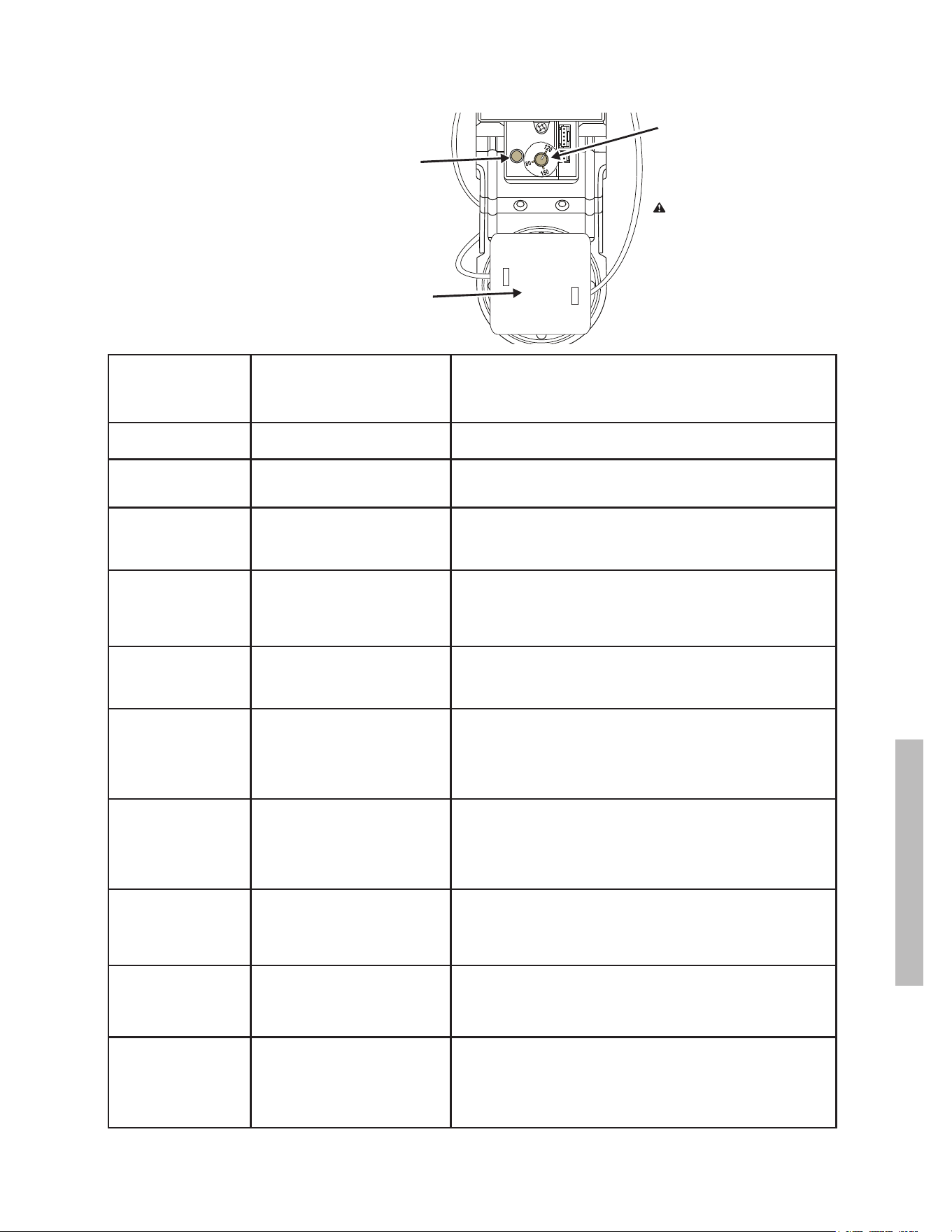
Adjust the thermostat to the desired
temperature seng using the “Setpoint
Knob”. NOTE: If the system diagnosc
yields any codes, reference the Diagnos-
c Code secon in this manual.
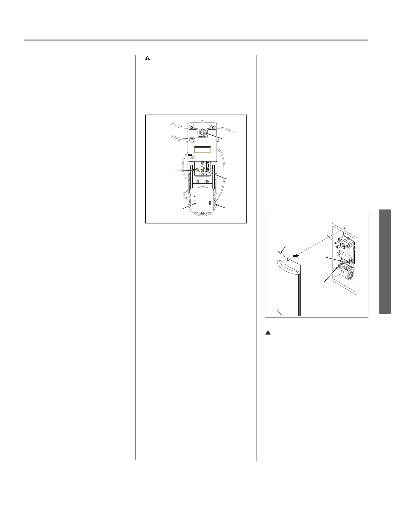
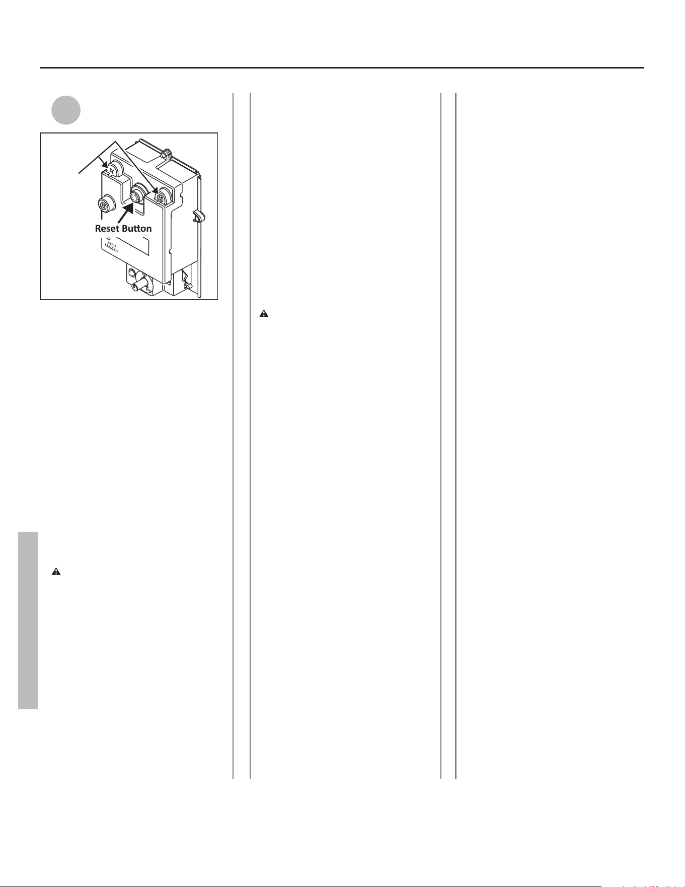
Figure 8
Electronic Thermostat (ET)
Diagnostic
LED Light
ECO Reset
Button
Setpoint
Knob
Remove Only After Power Is
Turned O When Replacing Element.
Plastic Guard
Upper
Element
WARNING! Electrical Shock Hazard
Do not remove the plasc guard from
over wiring.
Do not touch electrical wiring.
Failure to do so can result in death or
electrical shock.
WARNING! Electrical Shock Hazard
Do not remove the plasc guard from
over wiring.
Do not touch electrical wiring.
Failure to do so can result in death or
electrical shock.
Figure 9
Electronic
Thermostat (ET)
Setpoint
Knob
Thermistor
Wire Harness
Access Door
18 • Residenal Electric Water Heater Use and Care Guide
INSTALLATION
18 • Residenal Electric Water Heater Use and Care Guide
Smart Grid Technology
The electric Smart Grid will enable sig-
nicant improvements in electric power
reliability and quality through reducon
of peak power demand, while providing
consumers the knowledge and ability to
manage their energy consumpon and
ulity costs.
According to the Department of
Energy (DOE), since 1982 the growth
in peak electricity demand has exceed-
ed power transmission growth. This
has caused more frequent blackouts
and service interruptions, as well as an
increase in the costly reserve capac-
ity the power grid requires to meet
higher peak demands. The increased
demand for electrical power across
the nation has also led to higher peak
utility costs.
Smart appliances are one way to
help mitigate this problem. By using
advanced digital communication tech-
nologies, smart appliances will be
able to communicate with local power
company or home energy manage-
ment systems, and react accordingly
to save energy and money. For exam-
ple, during peak demand periods the
water heater may pause or delay its
power consumption and thus reduce
the load on the smart utility grid.
Additionally, smart appliances will also
communicate with consumers to let
them know how much energy they are
consuming. This will eventually allow
consumers to control their appliances,
manage energy usage, and to ulti-
mately save money.
Smart Grid Control
(Where Available)
Where available, Grid Communicaon
Adaptors may be supplied by the local
power company or purchased from lead-
ing retailers. Please contact your local
power company for more informaon.
To acvate Smart Grid Control, remove
the cover over the grid connecon pins
and plug in the grid communicaon
adaptor. See Figure 10. NOTE: use only
approved grid communicaon adaptors.
This will enable the power company to
communicate the peak demand periods
for the water heater’s power usage.
Aer this connecon has been made,
this will enable and allow acceptance of
the power company communicaon of
grid management requests. Unplugging
will disable this feature and will allow
the water heater to ignore grid manage-
ment requests.
NOTE: Smart Grid will be disabled when
the Grid Communicaon Adaptor is dis-
connected from the juncon box wiring
harness.
Smart Grid Connecon
Figure 10
Grid Connection
Pins
Junction Box
Grid
Communication
Adaptor
(May Be Supplied By Power Company)
(May Dier in Appearance)
WARNING! Electrical Shock Hazard
Disconnect power before servicing.
Replace all parts and panels before
operang.
Failure to do so can result in death or
electrical shock.
Residenal Electric Water Heater Use and Care Guide • 19
TROUBLESHOOTING
Setpoint
Knob
Diagnostic
LED Light
Plastic Guard
IMPORTANT: Before attempting to adjust the
thermostat, read the “Adjusting The Temperature”
section page 15.
The Electronic Thermostat (ET) is designed so
that it may control the water heater without the
Grid Communication Adaptor being operated,
see page 17.
If the instructions are not clear, contact a qualied
service technician.
DIAGNOSTIC CODE CHART Electronic Thermostat (ET)
WARNING! Electrical Shock Hazard
Do not remove the plasc guard from
over wiring.
Do not touch electrical wiring.
Failure to do so can result in death or
electrical shock.
(ET)
DIAGNOSTIC
LED
INDICATES CORRECTIVE ACTION*
LIGHT ON
(Green Flash)
Normal operation. None
NO LIGHT No electrical power to control board
or diagnostic LED light burned out.
1. Check for blown fuses or tripped breaker.
2. If diagnostic LED light is burned out, replace Electronic Thermostat
(ET).
1 FLASH
(Red)
Dry-fire, electrical power on with the
tank not completely full of water.
1. Turn off electrical power at breaker, add water.
2. Turn on electrical power at breaker.
3. See “Routine Maintenance” on page 25.
2 FLASHES
(Red)
Water temperature exceeded high
limit.
1. Turn off electrical power at the breaker.
2. Press the reset button (see Figure 8).
3. Turn on electrical power at breaker.
4. If error returns call a service technician for assistance.
3 FLASHES
(Red)
Upper thermistor sensor failure.
(Note: Upper thermistor sensor is
part of the ET)
1. Turn off electrical power at the breaker.
2. Replace Electronic Thermostat (ET).
3. Turn on electrical power at breaker.
4 FLASHES
(Red)
Upper element circuit failure.
(Note: Lower element is still operable)
1. Turn off electrical power at the breaker.
2. Check element circuits for resistance of 5-25 ohms (replace if required).
3. Check wires at elements and Electronic Thermostat (ET) for damage.
If this 4 flashes condition continues, replace Electronic Thermostat (ET).
4. Turn on electrical power at breaker.
5 FLASHES
(Red)
Lower element circuit failure.
(Note: Upper element is still operable)
1. Turn off electrical power at the breaker.
2. Check element circuits for resistance of 5-25 ohms (replace if required).
3. Check wires at elements and Electronic Thermostat (ET) for damage.
If this 5 flashes condition continues, replace Electronic Thermostat (ET).
4. Turn on electrical power at breaker.
6 FLASHES
(Red)
Electronic Thermostat (ET) failure
(Internal processor).
1. Turn off electrical power at the breaker. Now turn on electrical power to
see if error clears. If error has not cleared, replace Electronic Thermo-
stat (ET).
2. Turn on electrical power at breaker.
7 FLASHES
(Red)
Lower thermistor sensor failure. 1. Turn off electrical power at the breaker.
2. Check electrical connections at Electronic Thermostat (ET).
3. Replace Lower Thermistor Sensor.
4. Turn on electrical power at breaker.
8 FLASHES
(Red)
Electronic Thermostat (ET) error 1. Turn off electrical power.
2. Check wiring at Electronic Thermostat (ET) for damage.
3. Turn on electrical power at breaker.
4. If this code flashes condition continues, replace the Electronic
Thermostat (ET).
20 • Residenal Electric Water Heater Use and Care Guide
TROUBLESHOOTING
(ET)
DIAGNOSTIC
LED
INDICATES CORRECTIVE ACTION*
9, 10, 11 or 12 FLASHES
(Red)
Electronic Thermostat (ET) error 1. Turn off electrical power.
2. Check wiring at Electronic Thermostat (ET) for damage.
3. Turn on electrical power at breaker.
4. If this code flashes condition continues, replace the Electronic
Thermostat (ET).
*These instructions are brief and intended as guidance for a qualied person. If you lack the necessary
skills to perform these procedures call our Technical Assistance Hotline which is listed on the water
heater’s warranty sheet.
Residenal Electric Water Heater Use and Care Guide • 21
TROUBLESHOOTING
WARNING! Working near an
energized circuit can result in severe
injury or death from electrical shock.
WARNING! When you are nished,
be sure all covers are secured to
reduce the risk of re and electric
shock.
No Hot Water
The most likely reasons for an electric wa-
ter heater to produce NO hot water are:
• No electric power—a common prob-
lem with new installaons
• Burned out upper element (Dry
Fired) — a common problem with
new installaons
• Tripped Energy Cut O (red buon
on upper thermostat)
• The water heater’s inlet and outlet
connecons are reversed (usually
only in new installaons)
• Broken upper thermostat (or wiring)
• A leak in the hot water side of the
plumbing system that exceeds the
water heater’s heang capacity and
makes it appear that the water heater
is producing lile to no hot water
Follow these steps to diagnose and
correct common electrical problems:
1
Check the electric power to
the water heater. No hot
water is oen caused by a
problem with the home’s electrical
wiring or circuit breakers. You’ll need a
non-contact circuit tester. Follow these
guidelines:
• Locate the water heater’s circuit
breaker and turn it o (or remove the
circuit’s fuses).
• Locate the electrical juncon box on
top of the water heater and remove
the cover.
• Idenfy the two power wires. The
power wires are usually black/black
or black/red—the green or copper
wire is the ground wire.
• Turn the circuit breaker back on
(or install the fuses) and check the
power on both incoming power wires
using a non-contact circuit tester.
• Turn the power o and replace the
cover on the electrical juncon box.
If the water heater is not geng
power, contact a qualied person to
have your home’s wiring or circuit
breakers checked.
2
Check the upper heang
element. If the water heater is
geng electrical power, check
to see if the upper heang element has
burned out. If the upper element is
burned out, you’ll have no hot water.
To check the upper element, you’ll
need a mulmeter capable of reading
resistance.
• Turn the power OFF at the circuit
breaker or remove fuses.
• Remove the upper access panel.
• Remove the insulaon to access the
upper thermostat and heang ele-
ment.
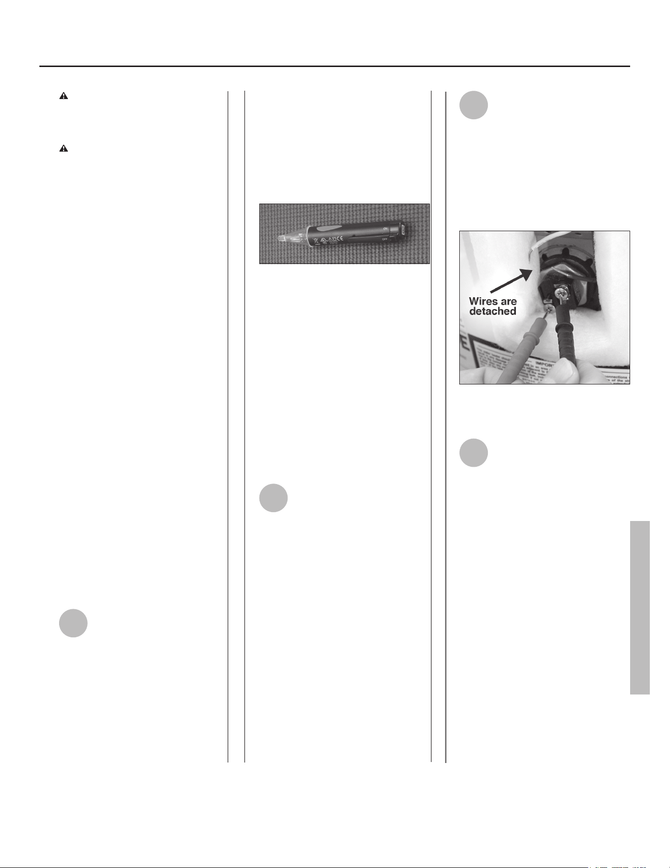
3
Check the top two screws of
the upper thermostat using a
non-contact circuit tester and
conrm that power is o (screw
terminals 1 and 3 in photo on next
page).
• With the electrical power o, remove
the two power wires from the upper
heang element.
4
Check the resistance of the
upper heang element using
a mulmeter. Measure the
resistance between the two screw
terminals on the upper heang
element. A good element will have a
resistance ranging between 5 and 25
Ohms. If the resistance is:
Outside this range. Replace the ele-
ment (see the Roune Maintenance
secon on page 26). On a new water
heater, a burned out upper heang
element is almost always caused by
turning the power on before the tank
was completely full of water (Dry Fire).
(See Step 8 in the Installaon secon.)
Within this range. Reaach the power
wires, making sure the wires are in
good condion and the connecons
are clean and ght. Next, check the
following:
Use a non-contact circuit tester to check for
electrical power.
Use a mulmeter to check the resistance of the
upper heang element.
TROUBLESHOOTING
22 • Residenal Electric Water Heater Use and Care Guide
5
Check/Reset Energy Cut O
(ECO) Buon.
The Energy Cut O (ECO) shuts o pow-
er to the water heater’s elements if the
temperature of the water in the tank
gets too hot. If the ECO has tripped,
you’ll have no hot water. A tripped ECO
can usually be reset, but you should
have a qualied person invesgate the
cause of the overheang and repair the
problem. Do not turn the power back
on unl the cause of the overheang
has been idened and repaired.
To check the Energy Cut O (ECO)
• Turn o the power to the water
heater.
WARNING! Working near an
energized circuit can result in severe
injury or death from electrical shock.
Check power wires in the electrical
juncon box with a non-contact circuit
tester to make sure power is o.
• Press the red ECO reset buon (see
photo above).
• The ECO was tripped if you hear a
click when it is reset. In most cases,
a tripped ECO indicates that the tank
overheated due to a problem with
one of the elements or thermostats—
have a qualied person check the up-
per and lower elements and thermo-
stats and replace if necessary.
• The ECO was not tripped if you didn’t
hear a click. In that case, the upper
thermostat should be checked by a
qualied person.
• Replace the insulaon and the upper
access panel.
WARNING! Be sure all covers are
secured to reduce the risk of re and
electric shock.
Insucient Hot Water
or Slow Hot Water
Recovery
WARNING! Because of the in-
creased risk from scalding, if you set
the water heater’s thermostat(s)
higher than 120°F, Thermostac Mixing
Valves at each point-of-use are
parcularly important (see page 4).
If the hot water is simply not warm
enough, there are several possible
causes:
• Faulty Thermostac Mixing Valve in a
faucet or shower control (check other
faucets in the house for hot water)
• One (or both) of the thermostats set
too low
• Water heater’s capacity too small (or
usage too high)
• Reversed plumbing connecons or
melted dip tube (usually found soon
aer new installaon)
• Plumbing leak
• Bad lower heang element (or lower
thermostat)
• Low supply voltage
Thermostac Mixing Valves. If the
hot water is simply not warm enough,
make sure the faucet you are checking
doesn’t have a defecve Thermostac
Mixing Valve. Many shower controls
now have built-in mixing valves. If
these devices fail, they can reduce the
amount of hot water the shower or
faucet delivers even though there is
plenty of hot water in the tank. Always
check the water temperature at several
faucets to make sure the problem is not
in a faucet or shower control.
Thermostats set too low. If the water
temperature at several faucets is too
cool, adjust the thermostat(s) accord-
ing to the instrucons in Step 10 of the
Installaon secon of this manual.
Undersized water heater. If your water
heater runs out of hot water too quick-
ly, it may be too small for your needs. If
the water heater is old, consider replac-
ing it with a larger model. If the water
heater is in good condion, you may
be able to meet your family’s hot water
needs with the exisng water heater by
installing Thermostac Mixing Valves at
each point-of-use and then turning the
thermostat(s) to a higher seng. See
page 15, step 10.
You can also reduce your home’s hot
water needs by washing clothes in cold
water, installing ow restrictors on
shower heads, repairing leaky faucets,
and taking other conservaon steps.
Reversed connecons or melted dip
tube. Check the hot and cold connec-
ons and make sure your home’s hot
water pipe is connected to the hot wa-
ter outlet on the water heater. Usually,
reversed connecons are found soon
aer the installaon of a new unit. If
copper pipes were soldered while they
were aached to the water heater, the
dip tube may have melted. The dip tube
is a long plasc tube inside the tank
aached to the cold water inlet. If the
dip tube has melted, it can be replaced
by removing the cold water inlet con-
necon, removing the old dip tube and
installing a new one.
Plumbing leak. Even a small leak in the
hot water side of the home’s plumbing
system can make it appear that the wa-
ter heater is producing lile to no hot
water. Locate and repair the leak.
Lower heang element not working.
If the lower heang element (or, more
THERMINALS
“1” and “3”
Energy Cut O (ECO) buon
TROUBLESHOOTING
Residenal Electric Water Heater Use and Care Guide • 23
TROUBLESHOOTING
rarely, the lower thermostat) is not
working, you will have some hot water
but not as much as before. Because
the lower element does most of the
work, the lower element usually wears
out before the upper element. Replace
the lower element and/or thermostat
if necessary (see page 26-27).
Temperature Too High
If the water temperature is too hot:
• Install or adjust the Thermostac
Mixing Valves for each point-of-use
(see manufacturer’s instrucons), or
• Adjust the thermostat(s) on the wa-
ter heater (see Step 10 in the installa-
on secon of this manual).
A nonfunconing thermostat or a
shorted heang element can cause ex-
tremely hot water. If the Temperature
and Pressure Relief Valve (T&P Valve)
releases large amounts of very hot
water, it is likely due to a shorted heat-
ing element, or more rarely a nonfunc-
oning thermostat, or the thermostat
does not t snuggly against the tank.
Very high water temperatures can also
cause the Energy Cut O (ECO) to trip
(see page 27). Turn power o unl this
problem is xed.
Low Water Pressure
Check both the cold and hot water at a
sink to determine if the lower pressure
is only on the hot water side. If both hot
and cold faucets have low pressure, call
your local water ulity. If the low pres-
sure is only on the hot water side, the
primary causes of this are:
• Melted heat traps or dip tube. Solder-
ing copper pipes while they are con-
nected to the water heater can melt
the heat traps inside the hot and cold
water connecons or the dip tube
(cold water side). Melted heat traps or
a melted dip tube can restrict the ow
of hot water. If that’s the case, replace
the heat traps or dip tube.
• Parally closed supply valve. Open
the water heater’s supply valve fully.
Drips from T&P Relief
Valve Discharge Pipe
A small amount of water dripping from
the Temperature and Pressure (T&P)
Relief Valve usually means the home’s
water pressure is too high or you need
a properly sized and pressurized Ther-
mal Expansion Tank. Refer to Step 1 in
the Installaon secon of this manual
for more informaon. A large amount
of hot water coming from the T&P
discharge pipe may be due to the tank
overheang.
WARNING! Do not cap or plug the
T&P relief valve or discharge pipe, and
do not operate the water heater
without a funconing T&P Relief Valve
- this could cause an explosion.
Water pressure too high. High water
pressure can cause the T&P Relief
Valve to drip. Install a Pressure Reduc-
ing Valve (PRV) on the main cold water
supply line. Adjust the PRV to between
50 and 60 psi.
Thermal Expansion Tank. Install a
Thermal Expansion Tank. If a Thermal
Expansion Tank is already installed and
the T&P Relief Valve discharge pipe
drips, the Thermal Expansion Tank may
be pressurized to the wrong pres-
sure or the internal bladder may be
defecve. Refer to the instrucons that
came with the Thermal Expansion Tank
for more informaon.
Debris. In rare cases, debris can sck
inside the T&P Relief Valve prevenng
the valve from seang fully. In that
case, the T&P Relief Valve discharge
pipe will drip. You may be able to clear
debris from the T&P Relief Valve by
manually operang the valve, allow-
ing small quanes of water to ush
out the debris. Refer to the T&P Relief
Maintenance secon of this manual.
WARNING! When manually operat-
ing the temperature-pressure relief
valve, make sure that no one is in
front of or around the discharge out-
let. The water may be extremely hot
and could cause severe burns. Also
ensure that the water discharge will
not cause property damage.
If the water pressure is between 50
and 60 psi, a Thermal Expansion Tank
is installed and properly pressurized,
and the valve has been cleared of any
debris, and it sll drips, the valve may
be broken—have a qualied person
replace the T&P relief valve.
Water Odor
Harmless bacteria normally present in
tap water can mulply in water heat-
ers and give o a “roen egg” smell.
Although eliminang the bacteria that
causes “smelly water” with a Chlorina-
on system is the only sure treatment,
in some cases, the standard anode
rod that came with your water heater
can be replaced with a special zinc
anode rod which may help reduce or
eliminate the odor. Contact a qualied
person.
NOTE: To protect the tank, an anode rod
must be installed in the water heater at
all mes or the warranty is void.
In cases where the “roen egg” smell
is pronounced, you can raise the tank
temperature to 140°F in order to re-
duce bacteria growth in the tank.
WARNING! Because higher
temperatures increase the risk of
scalding, if you set the thermostat(s)
higher than 120°F, Thermostac
Mixing Valves at each point-of-use are
parcularly important (see page 4). ■
TROUBLESHOOTING
MAINTENANCE
MAINTENANCE
Roune Maintenance
Roune maintenance will help your
water heater last longer and work more
eciently. If you can’t perform these
roune maintenance tasks yourself,
contact a qualied person.
Water Heater Maintenance
Aer the rst six months, drain and
ush the water heater and inspect the
anode rod. Depending on the hard-
ness of your water, repeat this process
at least annually, or more frequently if
needed. From me to me you may
need to replace a heang element or a
thermostat. All three maintenance tasks
are described below.
Draining and Flushing the
Water Heater
Tap water contains minerals that can
form lime deposits on heang elements
or sediment in the boom of the tank.
The amount of lime deposits or sedi-
ment depends on the hardness of your
tap water. The rate at which sediment
builds up depends on water quality and
hardness in your area, the tempera-
ture sengs, and other variables. We
recommend draining and ushing the
water heater aer the rst six months
of operaon to determine the amount
of sediment build up. Draining sedi-
ment extends the life of the tank, heat-
ing elements, and drain valves.
• In areas with very hard water, remove
and check the heang elements
whenever you drain the tank. If you
have heavy lime deposits on heang
elements, you will need to replace
them more oen.
• Sediment may form large masses that
can prevent the tank from draining.
Have a qualied person use a de-liming
agent suitable for potable water to
remove the sediment buildup.
• In most cases, it is easier and cheaper
to replace lime-encrusted elements
than trying to remove heavy lime
deposits.
To drain and ush the tank:
1
Locate the water heater’s
circuit breaker and turn it OFF
(or remove the circuit’s fuses).
2
Open a hot water faucet and
let the hot water run unl it is
cool.
WARNING! Be sure the water runs
cool before draining the tank to reduce
the risk of scalding.
3
Connect a garden hose to the
drain valve and place the other
end of the hose in a drain,
outside, or in buckets.
4
Turn the cold water supply
valve OFF.
5
Open the drain valve on the
water heater.
6
Open a hot water faucet to
help the water in the tank
drain faster.
NOTICE: DO NOT turn electrical power
back on unless the tank is completely
full of water.
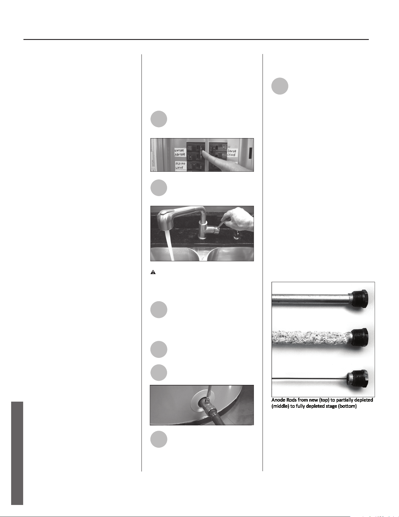
7
Remove and inspect the anode
rod (see Repair Parts Illustra-
on on back cover for locaon
of the anode rod). Replace the anode
rod if it is depleted. Turn power o. Run
hot water unl it’s cool. Turn cold water
supply valve o. Open a hot water
faucet to depressurize tank. Locate and
remove the black plasc cover marked
“Anode Rod”. Use a “key hole” saw or
similar tool to remove the foam
insulaon covering the anode rod. Once
the anode rod is exposed, use a 11/16”
socket wrench with an extension to
remove it. Inspect the anode rod and
replace if depleted. Apply Thread
sealant tape or pipe joint compound
and reinstall the anode rod ghtly. It is
not necessary to replace the foam
removed to access the anode. Turn cold
water supply valve on. When hot water
runs full, close hot water faucet. Check
for leaks and repair if necessary. Turn
power on.
Anode Rod. The anode rod is a sacricial
metal rod that helps reduce corrosion
and premature failure (leaks) in the tank.
The anode rod is a consumable item.
Inspect the anode rod aer the rst six
months of operaon when you drain and
24 • Residenal Electric Water Heater Use and Care Guide
Residenal Electric Water Heater Use and Care Guide • 25
MAINTENANCE
ush the tank. Replace the anode rod if
it is substanally worn out or depleted.
Thereaer, inspect the anode rod an-
nually or more frequently if needed. If
you use a water soener, your anode
rod will deplete faster than normal.
Inspect the anode rod more frequently,
replacing the anode rod as needed.
Obtain new anode rods from your local
hardware stores or have a qualied
person replace it. (Anode rods are a
consumable item and are not covered
under warranty).
8
If the sediment was present
when the tank was drained,
ush the tank by opening the
cold water supply valve and leng the
water run unl no more sediment
drains from the tank. Close the drain
valve when you are done.
NOTICE: Do not turn power back on
unl the tank is completely full of wa-
ter. For complete instrucons on lling
the tank, follow Step 8 in the Installa-
on secon.
9
Rell the tank by opening the
cold water supply valve. Make
sure a hot water faucet is
open and the drain valve is closed.
Allow the hot water to run full for at
least three minutes to make sure the
tank has all the air removed and is
completely full of water. Failure to
perform this step can cause the upper
heang element to burn out. Once you
are certain the tank is completely full
of water, close the hot water faucet.
10
Restore power to the water
heater. It may take two hours
for the tank to heat up.
Replacing the Heang Element
WARNING! Working on an ener-
gized circuit can result in severe injury
or death from electrical shock. Turn
power o. Check wires with a non-
contact circuit tester to make sure
power is o. When you are nished,
be sure all covers are secured to
reduce the risk of re and electric
shock.
If you are not comfortable replacing a
heang element or thermostat your-
self, have this work done by a qualied
person. To replace the heang ele-
ment, you’ll need the following tools
and supplies:
• Always turn power OFF and check
the power wires with a non-contact
circuit tester before working on the
water heater.
• Check your water heater’s data plate
for the correct waage and voltage.
Heang elements are available at
most hardware stores.
• Some regular sockets (1 1/2 inch)
may work, but regular sockets are
oen beveled and may slip. Inexpen-
sive element wrenches are available
at local hardware stores.
• Garden hose to drain the tank
• Hand dishwashing soap to lubricate
the gasket
• A clean cloth to clean the threaded
opening
• A at blade and a Phillips screwdriver
Steps for Replacing the Heang
Element:
1
Turn the power OFF at the
circuit breaker or remove fuses.
2
Open the electrical juncon
box on top of the water
heater. Using a non-contact
circuit tester, check the power wires to
make certain the power is OFF.
3
Open a hot water faucet and
let the hot water run unl it is
cool.
WARNING! Be sure the water runs
cool before draining the tank to
reduce the risk of scalding.
Non-Contact Circuit Tester
Heang Element (with gasket)
Element Wrench
MAINTENANCE
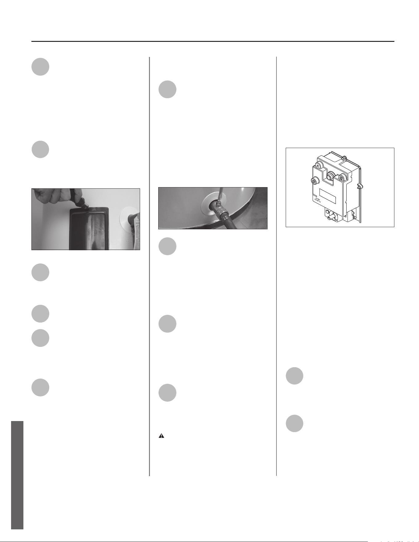
4
Connect a garden hose to the
drain valve and place the other
end of the hose in a drain or
outside (or use buckets). Turn OFF the
cold water valve that supplies the water
heater. Open the drain valve on the
water heater. Opening a hot water
faucet will help the tank drain faster.
5
Remove the upper or lower
access panel on the water
heater, and then fold back the
insulaon and remove the plasc
element/thermostat cover.
6
With the tank drained and
power o, remove the power
wires from the element you
intend to replace.
7
Remove the bad element using
an element wrench.
8
Make sure the new element is
the correct replacement by
referring to the water heater’s
data plate for voltage and waage
informaon.
9
Clean the threads in the tank
opening with a rag. Insert the
new element equipped with a
rubber gasket. NOTE: Use a drop of
hand dishwashing liquid to lubricate the
gasket to help avoid damaging the
gasket as it is being ghtened. Tighten
with an element wrench.
NOTICE: Do not turn power back on unl
the tank is completely full of water. For
complete instrucons on lling the tank,
follow Step 8 in the Installaon secon.
10
Rell the tank by opening the
cold water supply valve. Make
sure a hot water faucet is open
and the drain valve is closed. Allow the
hot water to run full for at least three
minutes to make sure the tank has all
the air removed and is completely full
of water. Failure to perform this step
can cause the upper heang element to
burn out. Once you are certain the tank
is completely full of water, close the hot
water faucet.
11
Check the newly installed
element for leaks. If a leak is
present, ghten the element
unl the leak stops. If you cannot stop
the leak, drain the tank and remove the
element. Inspect the gasket for dam-
age. If the gasket is damaged, replace
the gasket and re-install the element.
12
Once the element is success-
fully installed and there are no
leaks, replace the power wires,
thermostat cover, insulaon, and access
panel. Make sure all wire connecons
are ght. Replace the cover on the
electrical juncon box.
13
Restore power to the water
heater. It may take two hours
for the tank to heat up.
Replacing the Thermostat
WARNING! Working on an ener-
gized circuit can result in severe injury
or death from electrical shock. Turn
power o. Check wires with a non-
contact circuit tester to make sure
power is o. When you are nished, be
sure all covers are secured to reduce
the risk of re and electric shock.
To replace the thermostat, you’ll need
the following tools and supplies:
• A non-contact circuit tester. Always
turn power OFF and check with a non-
contact circuit tester before working on
the water heater.
• A replacement thermostat (available
at hardware stores). Take the old
thermostat to the store to ensure the
replacement thermostat is correct.
• A business card to check the gap be-
tween the thermostat and the tank
• Tape and a permanent marker to
mark the wires
• A at blade and a Phillips screwdriver
Steps for Replacing the
Thermostat:
1
Turn the power OFF at the
circuit breaker or remove fuses.
NOTICE: It is not necessary to drain the
tank to replace a thermostat.
2
Open the electrical juncon box
on top of the water heater. Using
a non-contact circuit tester, check
the power wires to make certain the
power is OFF.
MAINTENANCE
26 • Residenal Electric Water Heater Use and Care Guide
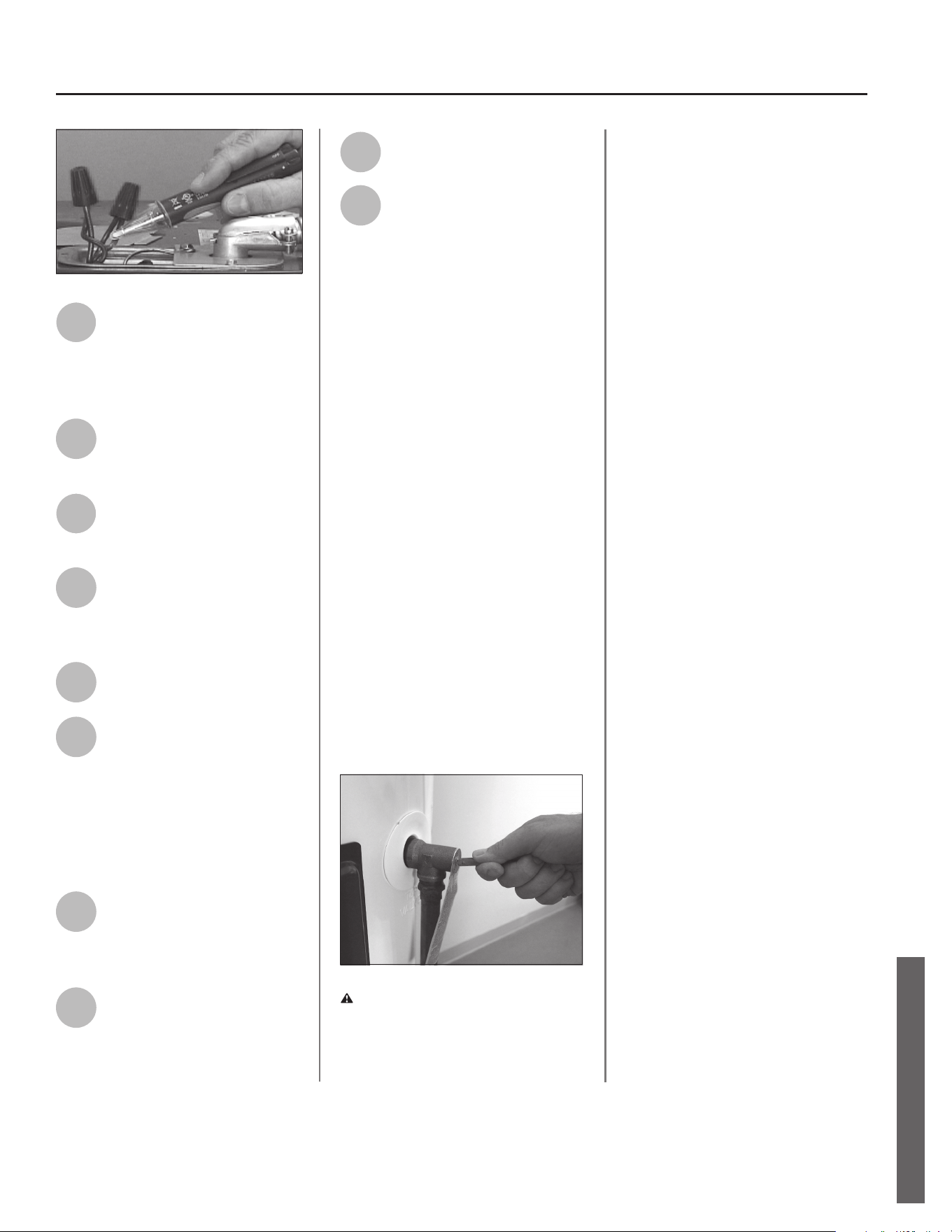
Residenal Electric Water Heater Use and Care Guide • 27
MAINTENANCE
3
Remove the upper or lower
access panel on the water
heater and carefully fold back
the insulaon and plasc element/
thermostat cover.
4
Make sure the replacement
thermostat matches the
original thermostat.
5
Mark the wires with tape so
you’ll know how to put them
back on.
6
Disconnect the wires from the
bad thermostat and remove
the thermostat from the
metal mounng clip.
7
Install the new thermostat in
the metal mounng clip.
8
Make sure the new thermo-
stat ts snuggly against the
tank. You should NOT be able
to slip a business card between the
thermostat and the tank. If you can,
bend the thermostat mounng clip
unl the thermostat ts ghtly against
the tank.
9
Aach the wires following the
wiring diagram on the water
heater’s label. Make sure all
wire connecons are ght.
10
Replace the plasc element/
thermostat cover, insulaon,
and access panel.
11
Replace the cover on the
electrical juncon box.
12
Restore power to the water
heater. It may take two hours
for the tank to heat up.
T&P Relief Valve Maintenance
Read and follow the operang and
annual maintenance instrucons
provided by the manufacturer of the
T&P Relief Valve (yellow label aached
to T&P Relief Valve). If no label is at-
tached to the T&P Relief Valve, follow
the instrucons in this secon. Miner-
als in the water can form deposits
that cause the valve to sck or create
blocked passages, making the T&P
Relief Valve inoperave. Follow these
guidelines:
• At least annually, operate the T&P
Relief Valve manually to ensure the
waterways are clear and the valve
mechanism moves freely (above).
Before operang the valve manually,
check that it will discharge in a place
for secure disposal. If water does
not ow freely from the end of the
discharge pipe, turn OFF the power
to the water heater. Call a qualied
person to determine the cause.
WARNING! Hot water will be
released. Before operang the T&P
relief valve manually, check that it will
discharge in a safe place. If water does
not ow freely from the end of the
discharge pipe, turn the power to the
water heater OFF. Call a qualied
person to determine the cause.
• At least every ve years, have a quali-
ed person inspect the T&P Relief
Valve and discharge pipe. Damage
caused by corrosive water condions,
mineral deposits, or other problems
can only be determined when a qual-
ied person removes and inspects
the valve and its components.
• Note that a dripping T&P Relief Valve
is usually caused by the home’s water
pressure being too high or the lack
of a Thermal Expansion Tank. If your
T&P Relief Valve drips, see page 24.
■
MAINTENANCE
NOTES
28 • Residenal Electric Water Heater Use and Care Guide
NOTES
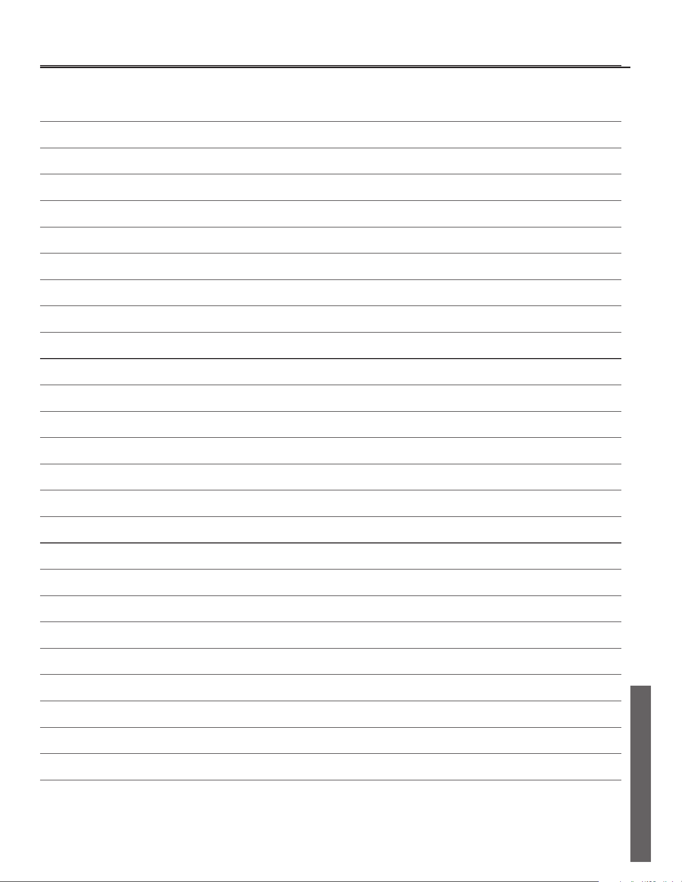
Residenal Electric Water Heater Use and Care Guide • 29
NOTES
NOTES
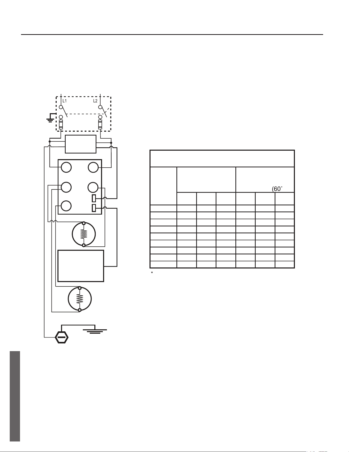
Residenal Electric Water Heater Use and Care Guide • 30
DIAGRAMS
Thermostat Wiring Diagram
120
V
1500*
2000
2500
3000
3500
4000
4500
5000
5500
15
20
30
30
-
-
-
-
-
WATT
LOAD
BRANCH CIRCUIT SIZING GUIDE
Based on N.E.C. NFPA NO. 70 - 1999
15
15
15
20
20
25
30
30
15
15
15
15
20
20
25
30
30
208
V
240
V
Recommend
Over Current
Protection Rating
12
10
10
8
-
-
-
-
-
14
14
14
12
10
10
10
10
14
14
14
12
12
10
10
10
10
120
V
208
V
240
V
Copper Wire Size
AWG Based on
N.E.C.
Table 310 - 16 C)
Wattages less than 1500 may be wired 14 gage with a maximum
15 amp protection.
ELECTRONIC
THERMOSTAT (ET)
FUSED DISCONNECT
OR CIRCUIT BREAKER
L 1
L 3
L 4
T 4
T 2
TEMPERATURE
SENSOR
UPPER
ELEMENT
LOWER
ELEMENT
GROUND
SCREW
ELECTRICAL
SERVICE
GROUND
RED
BLACK
YELLOW
RED
BLACK
BLUE
ON
JUNCTION
BOX COVER
BLACK - 4 WIRESBLACK - 2 WIRES
SMART GRID
WIRE HARNESS
GREEN
BLACK
RED
DIAGRAMS
100263189
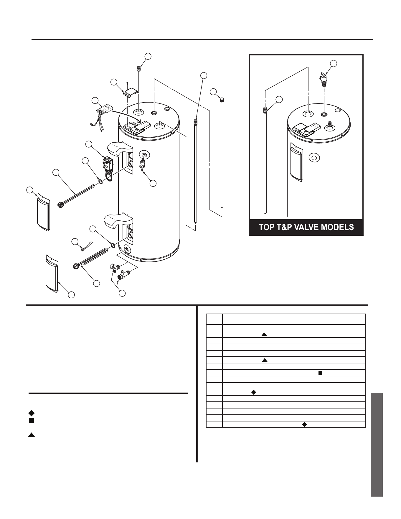
Residenal Electric Water Heater Use and Care Guide • 31
REPAIR PARTS
Repair Part Illustraon
REPAIR PARTS
Repair Parts
Repair parts may be ordered through your plumber,
local distributor, home improvement center, or by calling
Technical Assistance Hotline which is listed on the water
heater’s warranty sheet. When ordering repair parts,
always give the following information:
1. Model, serial and product number
2. Item number
3. Parts description
Repair Parts List
Legend
Special anode rod (See page 25)
Temperature and Pressure Relief Valve is required, but may not
be factory installed.
2
3
4
5
6
3
7
8
10
9
12
13
1
14
11
15
16
PARTS DESCRIPTION
1 ACCESS DOOR
2 UPPER ELEMENT
3 ELEMENT GASKET
4 ELECTRONIC THERMOSTAT (ET)
5 ACCESS DOOR
6 LOWER ELEMENT
7 DRAIN VALVE
8 TEMPERATURE AND PRESSURE RELIEF VALVE
9 JUNCTION BOX COVER
10 DIP TUBE (INCLUDES NIPPLE AND HEAT TRAP)
11 ANODE ROD
12 THERMISTOR SENSOR
13 SMART GRID WIRE HARNESS ASSEMBLY
14 HEAT TRAP
15 TOP TEMPERATURE AND PRESSURE RELIEF VALVE
16 HEAT TRAP/ANODE ROD COMBINATION
ITEM
No.

Copyright © 2018 American Water Heater Company
All Rights Reserved. Printed in the U.S.A.
Limited Warranty provided by Manufacturer.