Model
PDXWSEZ
Installation Instructions
EZ ASSEMBLY WALL
SLEEVE
For Use With Packaged Terminal Units
Please read these instructions completely before attempting installation.
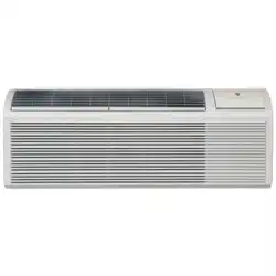
NOTE: These instructions apply to installation of the wall sleeve only through walls structurally adequate to support the
unit (i.e. sleeve, chassis, accessories.) If wall is not structurally adequate, a subbase or other means of support MUST
be made.
PDXWS(EZ) Wall Sleeve Assembly
(If required)- Locate the enclosed Weather Barrier and attach it to the
(outside) rear of assembled wall sleeve using the (4) supplier push pins,
aligning with frame of sleeve.
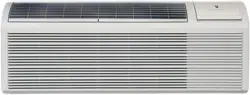
Figure 1:
Set Bottom Panel on a clean, flat and level surface.
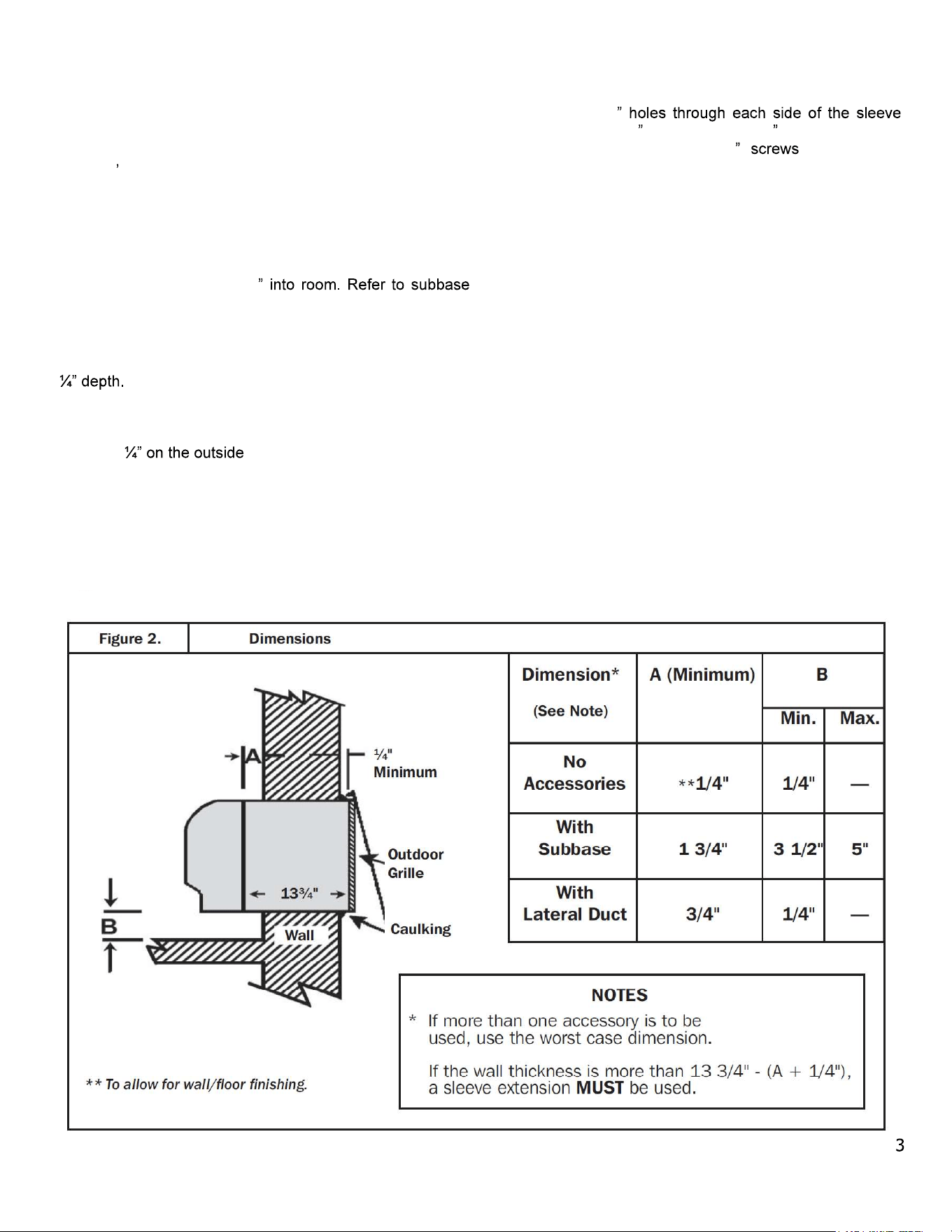
Figure 2:
Locate Left Side Panel. Align panel in the left Bottom
Panel slot. Fully inset Left Panel into Bottom Panel until locking tabs
engage.
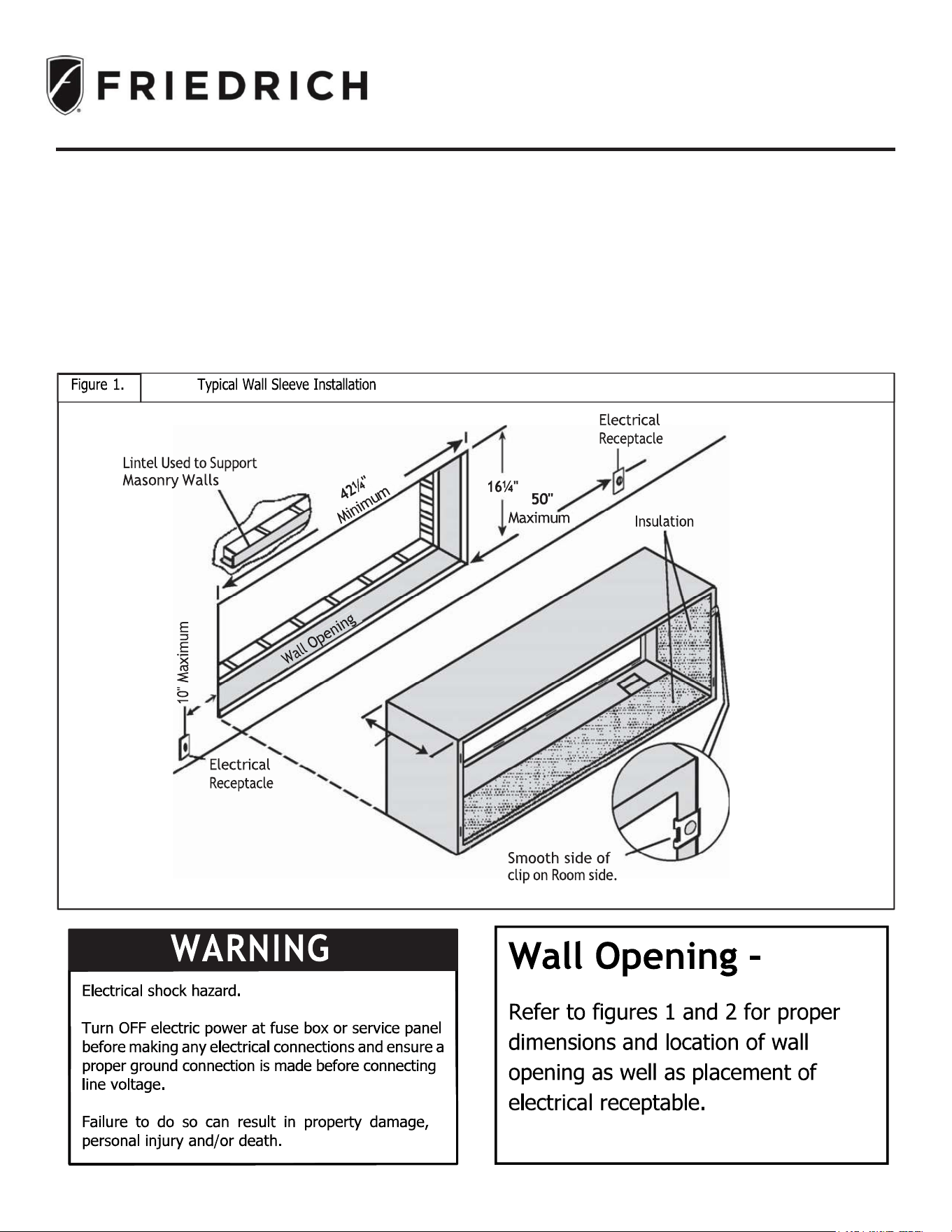
Figure 3:
Locate Right Side Panel. Align panel in the Right Bottom
Panel slot. Fully insert Right Panel into Bottom Panel until locking
tabs engage.
Figure 4:
Locate Top Panel and align with top Right and Left
Panels. Fully insert Top Panel into Right and Left Side Panels until
locking tabs engage.
Drain Kit
A field supplied condensate drain kit is required for total
elimination of cooling or heat pump condensate. When
installing a condensate drain kit, (either internal or external
drain), it s recommended that installation of the drain kit be
completed before installing the wall sleeve. Instructions for
drain kit installation are shipped with the drain kit.
Wall Structure
A subbase or other means of support MUST be used if
sleeve projects more than 8
installation instructions for additional information.
Sleeve Installation
The following instructions apply ONLY to walls less than 13
1. From inside the building, position wall sleeve in
opening and push through the wall so it protrudes at
least , note Figure 2.
2. Position the wall sleeve so that it is positioned with a
slight tilt towards the outside to facilitate condensate
drainage. It should be level side-to-side. Do NOT allow
any pitch toward the inside.
3. Drill two 3/16
approximately 4 from top and 4 from bottom of
sleeve. Screw four #10 x 1 (included) or
appropriate fasteners for your installation, through
holes in sides of opening.
NOTE: DO NOT put any screws or drill any holes in the
bottom of wall sleeve, unless required by the installation
of a PDXR10 Condensate Drain Kit.
4. Apply sealant around the wall sleeve where it projects
through the inside and outside wall surfaces. Apply
sealant to screw heads or tops of fasteners used in
Step #3.
NOTE: When sealing sleeve on outside of building, be
careful NOT to let sealant block the two-condensate
drain holes or the four overflow slots at the bottom
flange of the sleeve.
5. If chassis and exterior louver are to be installed later,
leave the weatherboard and center support in place,
otherwise remove and dispose of them.
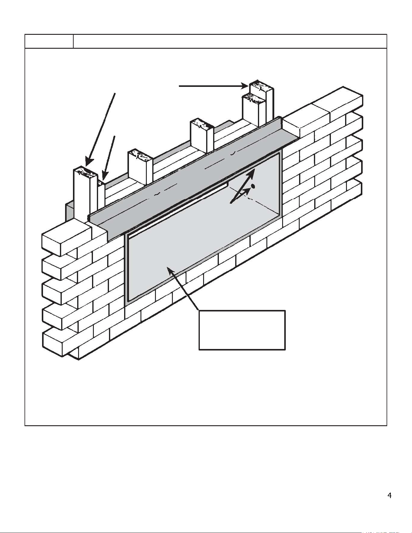
Figure 3.
Lintel
Installation
MAIN
STUDS
JACK
STUD
LINTEL
MOUNTING
SCREW HOLE
No holes are permitted in
the bottom of the case.
(Exception: PXDR10
Drain Kit)
Note the use of a lintel under the first course of bricks above
the wall sleeve. Do not use the wall sleeve as a lin- tel. The
mounting screw holes shown are to be made by the installer.
6. Provide a support lintel if the wall sleeve is installed in a concrete or masonry wall. (See Figure 3)