MILWAUKEE ELECTRIC TOOL CORPORATION
13135 W. Lisbon Road, Brookfield, WI 53005
Drwg. 2
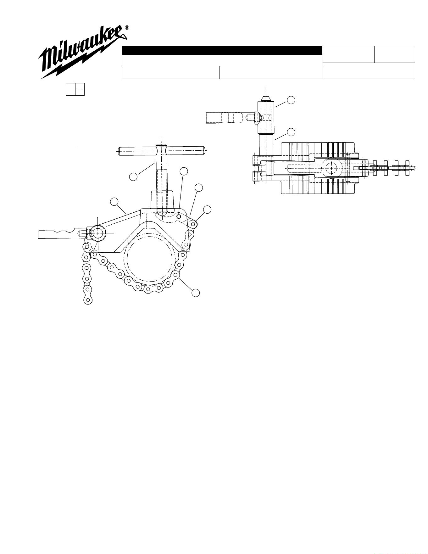
FIG. PART NO. DESCRIPTION OF PART QTY.
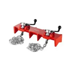
1 30-20-0061 Chain Clamp Body (1)
2 30-58-0051 Pivot Lever (1)
3 44-60-0010 Dowel Pin (1)
4 44-60-0080 Dowel Pin (1)
5 42-60-0010 Wrench Chain (1)
6 44-60-0040 Adapter Pin (1)
7 38-50-0010 Clamp Spindle (1)
« 8 45-16-0611 Pipe Clamp Shoe Post Assembly (1)
49-22-1012
54-40-9015
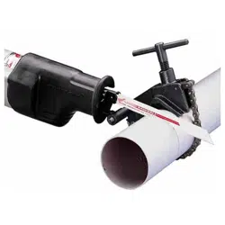
PIPE CLAMP SYSTEM
EXAMPLE:
Component Parts (Small #)
Are Included When Ordering
The Assembly (Large #).
REVISED BULLETIN DATE
SERVICE PARTS LIST
BULLETIN NO.
WIRING INSTRUCTION
CATALOG NO.
SPECIFY CATALOG NO. AND SERIAL NO. WHEN ORDERING PARTS
STARTING
SERIAL NUMBER
Mar. 2000
0
00
1
2
3
4
7
6
8
5
NOTES:
1. Press dowel pin Item 4, tapered side first to a depth of .015"
above to .045" below cast surface of pivot lever, Item 2.
2. Press dowel pin, Item 3, tapered side first to a depth of .045"
+/- .020" below cast surface of chain clamp body, Item 1.
3. Press adapter pin, Item 6, into chain clamp body, Item 1, flush to
a dead stop at shoulder on pin. A max gap of .005" between
shoulder and chain clamp body is permissible.