1
Installation Instructions for
*M9S96/*C9S96 & *M9S92
Single-Stage Gas Furnace
(Type FSP CATEGORY IV Direct
or Non Direct Vent Air Furnace)
(Type FSP CATÉGORIE IV Direct
ou four á air soué non direct)
Installer:
Affix all manuals
adjacent to the unit.
As a professional installer you have an obligation to know
the product better than the customer. This includes all
safety precautions and related items.
Prior to actual installation, thoroughly familiarize yourself
with this Instruction Manual. Pay special attention to all
safety warnings. Often during installation or repair it is
possible to place yourself in a position which is more
hazardous than when the unit is in operation.
Remember, it is your responsibility to install the product
safely and to know it well enough to be able to instruct a
customer in its safe use.
Safety is a matter of common sense...a matter of thinking
before acting. Most dealers have a list of specic good
safety practices...follow them.
The precautions listed in this Installation Manual are
intended as supplemental to existing practices. However,
if there is a direct conict between existing practices and
the content of this manual, the precautions listed here take
precedence.
RECOGNIZE THIS SYMBOL
AS A SAFETY PRECAUTION.
Brand is a registered trademark of Maytag Corporation or its related companies
and is used under license. All rights reserved.
IOG-2029
07/2021
*NOTE: Please contact your distributor or our website
for the applicable Specication Sheet referred to in
this manual.
These furnaces comply with requirements embodied
in the American National Standard / National Standard
of Canada ANSI Z21.47·CSA-2.3 Gas Fired Central
Furnaces.
19001 Kermier Rd., Waller, TX 77484
www.goodmanmfg.com • www.amana-hac.com
©2021 Goodman Manufacturing Company, L.P.
90% HEX
DO NOT LIFT
PRODUCT USING
HEAT EXCHANGER
O
NLY
PERSONNEL
THAT
HAVE
BEEN
TRAINED
TO
INSTALL
,
ADJUST
,
SERVICE
OR
REPAIR
(
HEREINAFTER
, “
SERVICE
”)
THE
EQUIPMENT
SPECIFIED
IN
THIS
MANUAL
SHOULD
SERVICE
THE
EQUIPMENT
. T
HE
MANUFACTURER
WILL
NOT
BE
RESPONSIBLE
FOR
ANY
INJURY
OR
PROPERTY
DAMAGE
ARISING
FROM
IMPROPER
SERVICE
OR
SERVICE
PROCEDURES
. I
F
YOU
SERVICE
THIS
UNIT
,
YOU
ASSUME
RESPONSIBILITY
FOR
ANY
INJURY
OR
PROPERTY
DAMAGE
WHICH
MAY
RESULT
. I
N
ADDITION
,
IN
JURISDICTIONS
THAT
REQUIRE
ONE
OR
MORE
LICENSES
TO
SERVICE
THE
EQUIPMENT
SPECIFIED
IN
THIS
MANUAL
,
ONLY
LICENSED
PERSONNEL
SHOULD
SERVICE
THE
EQUIPMENT
. I
MPROPER
INSTALLATION
,
ADJUSTMENT
,
SERVICING
OR
REPAIR
OF
THE
EQUIPMENT
SPECIFIED
IN
THIS
MANUAL
,
OR
ATTEMPTING
TO
INSTALL
,
ADJUST
,
SERVICE
OR
REPAIR
THE
EQUIPMENT
SPECIFIED
IN
THIS
MANUAL
WITHOUT
PROPER
TRAINING
MAY
RESULT
IN
PRODUCT
DAMAGE
,
PROPERTY
DAMAGE
,
PERSONAL
INJURY
OR
DEATH
.

2
TABLE OF CONTENTS
Safety Considerations ................................................4
Shipping Inspection .....................................................6
Electrostatic Discharge (ESD) Precautions .............6
To The Installer ..........................................................6
Product Application .....................................................7
Location Requirements & Considerations ...............8
Clearances and Accessibility ..................................9
Existing Furnace Removal ......................................... 9
Thermostat Location ................................................ 11
Combustion & Ventilation Requirements ................ 11
Installation Positions .............................................. 11
Horizontal Applications & Considerations .......... 11
Furnace Suspension ................................................. 11
Front Cover Pressure Switch Tube Location .... 11
Drain Trap and Lines ...............................................12
Leveling ...................................................................... 12
Alternate Electrical and Gas Line
Connections ..............................................................12
Drain Pan .................................................................... 12
Freeze Protection ....................................................12
Vent Pipe & Combustion Air Pipe ...........................13
Materials – Installations In The U.S.A. ................ 13
Materials – Installations In Canada ....................13
Pipe Installation ...................................................... 14
Pipe Sizing ..................................................................14
Vent Pipe Connection ..............................................15
Combustion Air Pipe Connection .........................15
Combustion Air Intake Options .............................16
Alternate Vent & Intake Pipe Connections..........16
Pipe Termination ......................................................17
Vent & Combustion Air Intake Measurements for
Standard Horizontal Terminations (Dual Pipe) .19
Vent/Intake Terminations For Installation of
Multiple Direct Vent Furnaces ...............................19
Concentric Vent Termination ................................19
Side Wall Vent Kit .................................................... 20
Condensate Drain Lines & Drain Trap ....................20
General Drain Information .....................................20
Field Supplied Drain .................................................21
Upflow Model Installed Vertically ......................21
Drain Exiting Right Side ..........................................21
Drain Exiting Left Side .............................................21
Upflow Model Installed Horizontally with Right
Side Down .................................................................. 21
Upflow Model Installed Horizontally with Left
Side Down .................................................................... 22
Upflow Model Installed Horizontally With Left
Side Down - Alternate ..............................................22
CounterFlow Model Installed Vertically ...........23
Drain Exiting Left Side .............................................23
Drain Exiting Right Side ..........................................23
Counterflow Model Installed Horizontally with
Right Side Down ........................................................ 24
Counterflow Model Installed Horizontally with
Left Side Down .......................................................... 24
Electrical Connections .............................................25
Wiring Harness ..........................................................25
115 Volt Line Connections ....................................... 25
115 Volt Line Voltage Connection of Accessories
(Humidifier and Electronic Air Cleaner) .............26
Connection of 24 Volt Humidifier .......................... 26
Junction Box Relocation ..........................................27
24 Volt Thermostat Wiring ........................................ 27
Fossil Fuel Applications ............................................27
Twinning ......................................................................28
Gas Supply and Piping .................................................28
High Altitude Installation ....................................... 28
Propane Gas Conversion .........................................28
Gas Valve ....................................................................29
Gas Piping Connections ...........................................29
Gas Piping Checks .....................................................31
Propane Gas Tanks and Piping ................................31
Circulating Air & Filters .........................................31
Duct work - Air Flow ................................................ 31
Checking Duct Static ................................................32
Bottom Return Air Opening [Upflow Models] ....32
Filters - Read This Section Before Installing The
Return Air Duct work ..............................................33
Filter Sizing Charts..................................................33
Horizontal Installations .........................................34
Startup Procedure & Adjustment ............................35
Furnace Cabinet ........................................................35
Drain Trap Priming ...................................................35
Furnace Operation .....................................................35
Furnace Startup ........................................................35
Gas Heat Sequence of Operation ...........................35
Heating Mode Speed Selection ...............................35
Continuous Fan Mode Speed Selection ................36
Cooling Mode Sequence of Operation ................. 36
Cooling Mode Speed Selection ..............................36
Furnace Shutdown ....................................................37
Gas Supply Pressure Measurement ......................37
Gas Pressure Test ....................................................37
Gas Manifold Pressure Measurement and
Adjustment .................................................................37
Gas Input Rate Measurement
(Natural Gas Only) ....................................................38
Temperature Rise ......................................................38
Operational Checks .................................................... 39

3
Safety Circuit Description .......................................39
Integrated Control Module ....................................39
Primary Limit ..............................................................39
Auxiliary Limit ............................................................39
Rollout Limit .............................................................39
Pressure Switches ....................................................39
Flame Sensor .............................................................39
Maintenance .................................................................39
Annual Inspection .....................................................39
Filters ............................................................................39
Filter Maintenance ...................................................39
Filter Removal ...........................................................39
Horizontal Unit Filter Removal ..............................40
Media Air Filter or Electronic Air Cleaner
Removal .......................................................................40
Burners .........................................................................40
Induced Draft and Circulator Blowers ............... 40
Condensate Trap and Drain System (Qualified
Servicer Only) ...........................................................40
Flame Sensor (Qualified Servicer Only) ..............40
Flue Passages (Qualified Servicer Only) ............. 40
Before Leaving an Installation ................................40
Repair and Replacement Parts ................................. 40
Functional Parts List- .............................................. 40
Troubleshooting ........................................................41
Airflow Tables - GC9S96 ...........................................45
Airflow Tables - GM9S92 ...........................................49
Airflow Tables - GM9S96 ...........................................56
Wiring Diagram ............................................................63
Special Instructions for Products Installed in the
State of Massachusetts ............................................. 64
Start-Up Checklist ......................................................65
TABLE OF CONTENTS
4
FROZEN AND BURST WATER PIPE HAZARD
F
AILURE
TO
PROTECT
AGAINST
THE
RISK
OF
FREEZING
MAY
RESULT
IN
PROPERTY
DAMAGE
.
S
PECIAL
PRECAUTIONS
MUST
BE
MADE
IF
INSTALLING
FURNACE
IN
AN
AREA
WHICH
MAY
DROP
BELOW
FREEZING
. T
HIS
CAN
CAUSE
IMPROPER
OPERATION
OR
DAMAGE
TO
EQUIPMENT
. I
F
THE
FURNACE
ENVIRONMENT
HAS
THE
POTENTIAL
OF
FREEZING
,
THE
DRAIN
TRAP
AND
DRAIN
LINE
MUST
BE
PROTECTED
. T
HE
USE
OF
ACCESSORY
DRAIN
TRAP
HEATERS
,
ELECTRIC
HEAT
TAPE
AND
/
OR
RV
ANTIFREEZE
IS
RECOMMENDED
FOR
THESE
INSTALLATIONS
.
CAUTION
T
O
PREVENT
PERSONAL
INJURY
OR
DEATH
DUE
TO
IMPROPER
INSTALLATION
,
ADJUSTMENT
,
ALTERATION
,
SERVICE
OR
MAINTENANCE
,
REFER
TO
THIS
MANUAL
. F
OR
ADDITIONAL
ASSISTANCE
OR
INFORMATION
,
CONSULT
A
QUALIFIED
INSTALLER
,
SERVICER
AGENCY
OR
THE
GAS
SUPPLIER
.
WARNING
I
F
THE
INFORMATION
IN
THESE
INSTRUCTIONS
IS
NOT
FOLLOWED
EXACTLY
,
A
FIRE
OR
EXPLOSION
MAY
RESULT
CAUSING
PROPERTY
DAMAGE
,
PERSONAL
INJURY
OR
LOSS
OF
LIFE
.
D
O
NOT
STORE
OR
USE
GASOLINE
OR
OTHER
FLAMMABLE
VAPORS
AND
LIQUIDS
IN
THE
VICINITY
OF
THIS
OR
ANY
OTHER
APPLIANCE
.
D
O
NOT
TRY
TO
LIGHT
ANY
APPLIANCE
.
D
O
NOT
TOUCH
ANY
ELECTRICAL
SWITCH
;
DO
NOT
USE
ANY
PHONE
IN
YOUR
BUILDING
.
I
MMEDIATELY
CALL
YOUR
GAS
SUPPLIER
FROM
A
NEIGHBOR
’
S
PHONE
. F
OLLOW
THE
GAS
SUPPLIER
’
S
INSTRUCTIONS
.
I
F
YOU
CANNOT
REACH
YOUR
GAS
SUPPLIER
,
CALL
THE
FIRE
DEPARTMENT
.
I
NSTALLATION
AND
SERVICE
MUST
BE
PERFORMED
BY
A
QUALIFIED
INSTALLER
,
SERVICE
AGENCY
OR
THE
GAS
SUPPLIER
.
WHAT TO DO IF YOU SMELL GAS:
�
�
�
�
WARNING
H
EATING
UNIT
SHOULD
NOT
BE
UTILIZED
WITHOUT
REASONABLE
,
ROUTINE
,
INSPECTION
,
MAINTENANCE
AND
SUPERVISION
. I
F
THE
BUILDING
IN
WHICH
ANY
SUCH
DEVICE
IS
LOCATED
WILL
BE
VACANT
,
CARE
SHOULD
BE
TAKEN
THAT
SUCH
DEVICE
IS
ROUTINELY
INSPECTED
,
MAINTAINED
AND
MONITORED
.
IN
THE
EVENT
THAT
THE
BUILDING
MAYBE
EXPOSED
TO
FREEZING
TEMPERATURES
AND
WILL
BE
VACANT
,
ALL
WATER
-
BEARING
PIPES
SHOULD
BE
DRAINED
,
THE
BUILDING
SHOULD
BE
PROPERLY
WINTERIZED
,
AND
THE
WATER
SOURCE
CLOSED
.
IN
THE
EVENT
THAT
THE
BUILDING
MAY
BE
EXPOSED
TO
FREEZING
TEMPERATURES
AND
WILL
BE
VACANT
,
ANY
HYDRONIC
COIL
UNITS
SHOULD
BE
DRAINED
AS
WELL
AND
,
IN
SUCH
CASE
,
ALTERNATIVE
HEAT
SOURCES
SHOULD
BE
UTILIZED
.
WARNING
T
O
PREVENT
POSSIBLE
PROPERTY
DAMAGE
,
PERSONAL
INJURY
OR
DEATH
DUE
TO
ELECTRICAL
SHOCK
,
THE
FURNACE
MUST
BE
LOCATED
TO
PROTECT
THE
ELECTRICAL
COMPONENTS
FROM
WATER
.
WARNING
SAFETY CONSIDERATIONS
Adhere to the following warnings and cautions when
installing, adjusting, altering, servicing, or operating the
furnace. To ensure proper installation and operation,
thoroughly read this manual for specics pertaining to the
installation and application of this product.
This furnace is manufactured for use with natural gas. It
may be eld converted to operate on L.P. gas by using the
appropriate L.P. conversion kit listed in the PROPANE
GAS/HIGH ALTITUDE INSTALLATIONS section of this
manual
Install this furnace only in a location and position
as specied in LOCATION REQUIREMENTS &
CONSIDERATIONS section and INSTALLATION
POSITIONS section of this manual.
Provide adequate combustion and ventilation air to the
furnace as specied in COMBUSTION & VENTILATION
AIR REQUIREMENTS section of this manual.
Combustion products must be discharged to the outdoors.
Connect this furnace to an approved vent system only, as
specied in VENT/FLUE PIPE & COMBUSTION AIR PIPE
section of this manual.
Never test for gas leaks with an open ame. Use a
commercially available soap solution made specically
for the detection of leaks to check all connections, as
specied in GAS SUPPLY AND PIPING section of this
manual.
Always install a furnace to operate within the furnace’s
intended temperature-rise range with a duct system which
has external static pressure within the allowable range, as
specied on the furnace rating plate and OPERATIONAL
CHECKS section of these instructions.
When a furnace is installed so that supply ducts carry
air circulated by the furnace to areas outside the space
containing the furnace, the return air shall also be handled
by duct(s) sealed to the furnace casing and terminating
outside the space containing the furnace.
A gas-red furnace for installation in a residential
garage must be installed as specied in the LOCATION
REQUIREMENTS AND CONSIDERATIONS section of
this manual.
This furnace may be used as a construction site heater
only if certain conditions are met. These conditions are
listed in the PRODUCT APPLICATION section of this
manual.
5
Drain trap must be primed at time of installation. Trap is
internally partitioned; add water to both inlet ports until
water appears at both sides of the outlet opening. Failure
to prime trap at time of installation may have a negative
eect on combustion quality and pressure switch action.
WARNING
FIRE OR EXPLOSION HAZARD
Failure to follow the safety warnings exactly could result
in serious injury, death or property damage.
Never test for gas leaks with an open flame.
Use a commercially available soap solution made
specifically for the detection of leaks to check all
connections. A fire or explosion may result causing
property damage, personal injury or loss of life.
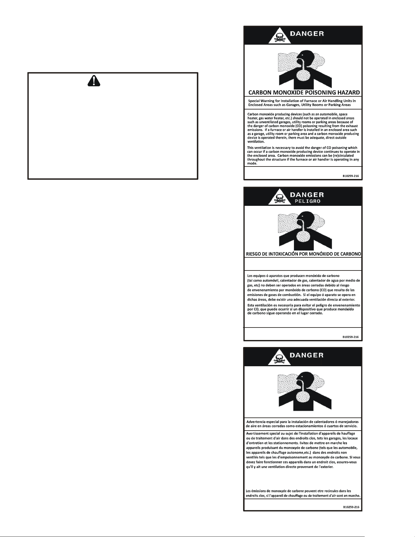
Advertencia especial para la instalación de calentadores ó
manejadoras
de aire en áreas cerradas como estacionamientos ó cuartos de servicio.
El monóxido de carbono puede causar enfermedades severas
como daño cerebral permanente ó muerte.
Las emisiones de monóxido de carbono pueden circular a través
del aparato cuando se opera en cualquier modo.
RISQUE D'EMPOISONNEMENT AU MONOXYDE DE CARBONE
Le monoxyde de
des
carbone peut causer des maladies graves telles que
dommages permanents au cerveau et meme la mort.
Cette ventilation est nécessaire pour éviter le danger d'intoxication
au CO pouvant survenir si un appareil produisant du monoxyde
de carbone continue de fonctionner au sein de la zone confinée.
CO can cause serious illness including permanent brain
damage or death.
6
AVERTISSEMENT
RISQUE D'INCENDIE OU D'EXPLOSION
Si les consignes de sécurité ne sont pas suivies à la lettre,
cela peut entraîner la mort, de graves blessures ou des
dommages matériels.
Ne jamais vérifier la présence de fuites de gaz au moyen
d'une flamme nue. Vérifier tous les raccords en utilisant
une solution savonneuse commerciale conçue
spécialement pour la détection de fuites. Un incendie ou
une explosion risque de se produire, ce qui peut entraîner
la mort, des blessures ou des dommages matériels.
Shipping Inspection
All units are securely packed in shipping containers
tested according to International Safe Transit Association
specications. The carton must be checked upon arrival
for external damage. If damage is found, a request for
inspection by carrier’s agent must be made in writing
immediately.
The furnace must be carefully inspected on arrival for
damage and bolts or screws which may have come loose
in transit. In the event of damage the consignee should:
1. Make a notation on delivery receipt of any visible
damage to shipment or container.
2. Notify carrier promptly and request an inspection.
3. With concealed damage, carrier must be notied as
soon as possible - preferably within ve days.
4. File the claim with the following support documents
within a nine month statute of limitations.
• Original or certied copy of the Bill of Lading, or
indemnity bond.
• Original paid freight bill or indemnity in lieu thereof.
• Original or certied copy of the invoice, showing trade
and other discounts or reductions.
• Copy of the inspection report issued by carrier’s
representative at the time damage is reported to
carrier.
The carrier is responsible for making prompt inspection of
damage and for a thorough investigation of each claim.
The distributor or manufacturer will not accept claims from
dealers for transportation damage.
ELECTROSTATIC DISCHARGE (ESD)
PRECAUTIONS
S
HOULD
OVERHEATING
OCCUR
OR
THE
GAS
SUPPLY
FAIL
TO
SHUT
OFF
,
TURN
OFF
THE
MANUAL
GAS
SHUTOFF
VALVE
EXTERNAL
TO
THE
FURNACE
BEFORE
TURNING
OFF
THE
ELECTRICAL
SUPPLY
.
WARNING
P
OSSIBLE
PROPERTY
DAMAGE
,
PERSONAL
INJURY
OR
DEATH
DUE
TO
FIRE
,
EXPLOSION
,
SMOKE
,
SOOT
,
CONDENSATION
,
ELECTRICAL
SHOCK
OR
CARBON
MONOXIDE
MAY
RESULT
FROM
IMPROPER
INSTALLATION
,
REPAIR
OPERATION
,
OR
MAINTENANCE
OF
THIS
PRODUCT
.
WARNING
NOTE: Discharge your body’s static electricity
before touching unit. An electrostatic discharge can
adversely aect electrical components.
Use the following precautions during furnace installation
and servicing to protect the integrated control module
from damage. By putting the furnace, the control, and the
person at the same electrostatic potential, these steps
will help avoid exposing the integrated control module to
electrostatic discharge. This procedure is applicable to
both installed and non-installed (ungrounded) furnaces.
1. Disconnect all power to the furnace. Do not touch the
integrated control module or any wire connected to the
control prior to discharging your body’s electrostatic
charge to ground.
2. Firmly touch a clean, unpainted, metal surface of the
furnaces near the control. Any tools held in a person’s
hand during grounding will be discharged.
3. Service integrated control module or connecting
wiring following the discharge process in step 2. Use
caution not to recharge your body with static electricity;
(i.e., do not move or shue your feet, do not touch
ungrounded objects, etc.). If you come in contact with
an ungrounded object, repeat step 2 before touching
control or wires.
4. Discharge your body to ground before removing a new
control from its container. Follow steps 1 through 3 if
installing the control on a furnace. Return any old or
new controls to their containers before touching any
ungrounded object.
TO THE INSTALLER
Before installing this unit, please read this manual
thoroughly to familiarize yourself with specic items which
must be adhered to, including but not limited to: unit
maximum external static pressure, gas pressures, BTU
input rating, proper electrical connections, circulating air
temperature rise, minimum or maximum CFM, and motor
speed connections.
7
PRODUCT APPLICATION
This furnace is primarily designed for residential home-heating
applications. It is NOT designed or certied for use in
mobile homes, trailers or recreational vehicles. Neither is it
designed or certied for outdoor applications. The furnace
must be installed indoors (i.e., attic space, crawl space, or
garage area provided the garage area is enclosed with an
operating door).
This furnace can be used in the following non-industrial
commercial applications:
Schools, Oce buildings, Churches, Retail stores, Nursing
homes, Hotels/motels, Common or oce areas
In such applications, the furnace must be installed with the
following stipulations:
• It must be installed per the installation instructions
provided and per local and national codes.
• It must be installed indoors in a building constructed on
site.
• It must be part of a ducted system and not used in a free
air delivery application.
• It must not be used as a “make-up” air unit.
• It must be installed as a two-pipe systems for
combustion air.
• All other warranty exclusions and restrictions apply
This furnace is an ETL dual-certied appliance and
is appropriate for use with natural or propane gas
(NOTE: If using propane, a propane conversion kit is
required).
Dual certication means that the combustion air inlet pipe
is optional and the furnace can be vented as a:
Non-direct vent (single pipe) central forced air furnace in
which combustion air is taken from the installation area or
from air ducted from the outside or,
Direct vent (dual pipe) central forced air furnace in which all
combustion air supplied directly to the furnace burners through
a special air intake system outlined in these instructions.
T
O
PREVENT
PROPERTY
DAMAGE
,
PERSONAL
INJURY
OR
DEATH
DUE
TO
FIRE
,
DO
NOT
INSTALL
THIS
FURNACE
IN
A
MOBILE
HOME
,
TRAILER
,
OR
RECREATIONAL
VEHICLE
.
WARNING
This furnace may be used as a construction site heater
ONLY if all of the following conditions are met:
• The vent system is permanently installed per these
installation instructions.
• A room thermostat is used to control the furnace.
Fixed jumpers that provide continuous heating
CANNOT be used and can cause long term
equipment damage. Bimetal thermostats, or any
thermostat aected by vibration, must not be used
during construction.
• Return air ducts are provided and sealed to the
furnace.
• A return air temperature range between 60ºF (16ºC)
and 80ºF (27ºC) is maintained.
• MERV 11 pleated minimum 4.0” thick (Example P/N
• AMP-11-2025-45) air lter(s) are installed in the
system and inspected daily and replaced as
needed during construction and upon completion of
construction.
• The input rate and temperature rise are set per the
furnace rating plate.
• The furnace must be installed as a two pipe system,
using 100% outside air for combustion during
construction.
• The furnace heat exchanger, components, duct
system, air lters and evaporator coils are thoroughly
cleaned following nal construction clean up by a
qualied person.
• All furnace operating conditions (including ignition,
input rate, temperature rise and venting) are veried
according to these installation instructions.
• Furnace doors must be in place on the furnace while
the furnace is operating in any mode.
• Damage or repairs due to failure to comply with these
requirements are not covered under the warranty.
NOTE: The Commonwealth of Massachusetts requires
that the following additional requirements must also
be met:
• Gas furnaces must be installed by a licensed plumber
or gas tter.
• A T-handle gas cock must be used.
• If the unit is to be installed in an attic, the
passageway to and the service area around the unit
must have ooring.
To ensure proper furnace operation, install, operate and
maintain the furnace in accordance with these installation
and operation instructions, all local building codes and
ordinances. In their absence, follow the latest edition of
the National Fuel Gas Code (NFPA 54/ANSI Z223.1), and/
or CAN/CSA B149.1-15 Installation Codes, local plumbing or
waste water codes, and other applicable codes.
A copy of the National Fuel Gas Code (NFPA 54/ANSI Z223.1)
can be obtained from any of the following:
American National Standards Institute
23 West 43rd Street, 4th Floor
New York, NY 10036
National Fire Protection Association
1 Batterymarch Park
Quincy, MA 02169-7471
CSA International
8501 East Pleasant Valley
Independence, OH 441311
The rated heating capacity of the furnace should be
greater than or equal to the total heat loss of the area to
be heated. The total heat loss should be calculated by an
approved method or in accordance with “ASHRAE Guide”
or “Manual J-Load Calculations” published by the Air
Conditioning Contractors of America.
8
A copy of the CAN/CSA B149.1-15 Installation Codes can
also be obtained from:
CSA International
178 Rexdale Boulevard
Etobicoke, Ontario, Canada M9W 1R3
LOCATION REQUIREMENTS &
CONSIDERATIONS
Follow the instructions listed below and the guidelines provided
in the Combustion and Ventilation Air Requirements section
when selecting a furnace location.
T
O
PREVENT
POSSIBLE
EQUIPMENT
DAMAGE
,
PROPERTY
DAMAGE
,
PERSONAL
INJURY
OR
DEATH
,
THE
FOLLOWING
BULLET
POINTS
MUST
BE
OBSERVED
WHEN
INSTALLING
THIS
UNIT
.
WARNING
P
OSSIBLE
PROPERTY
DAMAGE
,
PERSONAL
INJURY
OR
DEATH
DUE
TO
FIRE
,
EXPLOSION
,
SMOKE
,
SOOT
,
CONDENSATION
,
ELECTRICAL
SHOCK
OR
CARBON
MONOXIDE
MAY
RESULT
FROM
IMPROPER
INSTALLATION
,
REPAIR
OPERATION
,
OR
MAINTENANCE
OF
THIS
PRODUCT
.
WARNING
•
• Centrally locate the furnace with respect to the
proposed or existing air distribution system.
• Ensure the temperature of the return air entering the
furnace is between 55°F and 100°F when the furnace is
heating.
• Provide provisions for venting combustion products
outdoors through a proper venting system. Special
consideration should be given to vent/ue pipe routing
and combustion air intake pipe when applicable.
Refer to Vent/Flue Pipe and Combustion Air Pipe
-Termination Locations for appropriate termination
locations and to determine if the piping system from
furnace to termination can be accomplished within
the guidelines given. NOTE: The length of ue and/
or combustion air piping can be a limiting factor in the
location of the furnace.
• Locate the furnace so condensate ows downwards
to the drain. Do not locate the furnace or its
condensate drainage system in any area subject to
below freezing temperatures without proper freeze
protection.
• Ensure adequate combustion air is available for the
furnace. Improper or insucient combustion air
can expose building occupants to gas combustion
products that could include carbon monoxide. Refer
to Combustion and Ventilation Air Requirements.
• Set the furnace on a level oor to enable proper
condensate drainage. If the oor becomes wet or
damp at times, place the furnace above the oor on
a concrete base sized approximately 1-1/2” larger
than the base of the furnace. Refer to the Horizontal
Applications and Considerations for leveling of
horizontal furnaces.
• Ensure upow or horizontal furnaces are not installed
directly on carpeting, or any other combustible
material. The only combustible material allowed is
wood.
• A special accessory sub-base must be used for
upright counterow unit installations over any
combustible material (including wood). Refer to sub-
base instructions for installation details. (NOTE: A
sub-base will not be required if an air conditioning coil
is located beneath the furnace between the supply air
opening and the combustible oor.
• Exposure to contaminated combustion air will result in
safety and performance-related problems. Do not install
the furnace where the combustion air is exposed to the
following substances:
permanent wave solutions
chlorinated waxes or cleaners
chlorine-based
carbon tetrachloride
water softening chemicals
swimming pool chemicals
deicing salts or chemicals
halogen type refrigerants
printing inks
cleaning solutions (such as perchloroethylene)
paint removers
varnishes
hydrochloric acid
cements and glues
antistatic fabric softeners for clothes dryers
masonry acid washing materials
• Enclose a non-direct vent furnace if it is installed near
an area frequently contaminated by any of the above
substances. This protects the non-direct vent furnace
from airborne contaminants. To ensure that the
enclosed non-direct vent furnace has an adequate
supply of combustion air, provide air from a nearby
uncontaminated room or from outdoors. Refer to
the Combustion and Ventilation Air Requirements for
details.
• If the furnace is used in connection with a cooling coil
unit, install the furnace upstream or in parallel with the
cooling coil unit. Premature heat exchanger failure will
result if the cooling unit is placed ahead of the furnace.
• For vertical (upow or downow) applications, the
minimum cooling coil width shall not be less than
furnace width minus 1”. Additionally, a coil installed
above an upow furnace or under a counterow
furnace may be the same width as the furnace or may
be one size larger than the furnace. Example: a “C”
width coil may be installed with a “B” width furnace.
• For upow applications, the front of the coil and
furnace must face the same direction.
• If the furnace is installed in a residential garage,
position the furnace so that the burners and ignition
source are located not less than 18 inches (457 mm)
above the oor. Protect the furnace from physical
damage by vehicles.
• If the furnace is installed horizontally, ensure the
access doors are not on the “up/top” or “down/
bottom” side of the furnace.
9
• Do not connect this furnace to a chimney ue that
serves a separate appliance designed to burn solid
fuel.
• On Counterow Installations, the air conditioning coil
must be downstream on the supply (positive) side of
the furnace heat exchanger.
• Counterow Installation over a noncombustible oor.
Before setting the furnace over the plenum opening,
ensure the surface around the opening is smooth
and level. A tight seal should be made between the
furnace base and oor by using a silicone rubber
caulking compound or cement grout.
• Counterow Installation over a combustible oor.
If installation over a combustible oor becomes
necessary, use an accessory sub-base (see
Specication Sheet applicable for your model for
details.) A special accessory sub-base must be used
for upright counterow unit installations over any
combustible material including wood. Refer to sub-
base instructions for installation details. Follow the
instructions with the sub-base for proper installation.
Do not install the furnace directly on carpeting, tile, or
other combustible material other than wood ooring.
(NOTE: The sub-base will not be required if an air
conditioning coil is installed between the supply air
opening on the furnace and the oor.)
Position* Sides Rear Front Bottom Flue Top
Upflow 0" 0" 3" C 0" 1"
Horizontal 6" 0" 3" C 0" 6"
*M9S96* & *M9S92* Minimum Clearances To Combustible Materials (Inches)
C = If placed on combustible floor, floor MUST be wood only.
Position* Sides Rear Front Bottom Flue Top
Counterflow 0" 0" 3" NC 0" 1"
Horizontal 6" 0" 3" C 0" 6"
*C9S96* Minimum Clearances To Combustible Materials (Inches)
C = If placed on combustible floor, floor MUST be wood only.
NC = For installations on non-combustible floors only. A combustible subbase must be
used for installations on combustible flooring.
TOP
BOTTOM
SIDE SIDE SIDE
TOP
BOTTOM
Upflow Counterflow Horizontal
Figure 1
CLEARANCES AND ACCESSIBILITY
NOTES:
• For servicing or cleaning, a 24” front clearance is
required.
• Unit connections (electrical, ue and drain) may
necessitate greater clearances than the minimum
clearances listed above.
• Clearance in accordance with local installation
codes, the requirements of the gas supplier and the
manufacturer’s installation instructions.
• Dégaugement conforme aux codes d’installation
locaux, aux exigences du fournisseur de gaz et aux
instructions d’installation du fabricant.
• In all cases, accessibility clearance must take
precedence over clearances from the enclosure
where accessibility clearances are greater.
Installations must adhere to the clearances to combustible
materials to which this furnace has been design certied.
The minimum clearance information for this furnace is
provided on the unit’s clearance label. These clearances
must be permanently maintained. Clearances must
also accommodate an installation’s gas, electrical, and
drain trap and drain line connections. If the alternate
combustion air intake or vent/ue connections are used
additional clearance must be provided to accommodate
these connections. Refer to Vent/Flue Pipe and
Combustion Air Pipe for details.
NOTE: In addition to the required clearances to
combustible materials, a minimum of 24 inches
service clearance must be available in front of the unit.
A furnace installed in a conned space (i.e., a closet or utility
room) must have two ventilation openings with a total minimum
free area of 0.25 square inches per 1,000 BTU/hr of furnace
input rating. Refer to Specication Sheet applicable to your
model for minimum clearances to combustible surfaces. One
of the ventilation openings must be within 12 inches of the top;
the other opening must be within 12 inches of the bottom of
the conned space. In a typical construction, the clearance
between the door and door frame is usually adequate to
satisfy this ventilation requirement.
Existing Furnace Removal
NOTE: When an existing furnace is removed from
a venting system serving other appliances, the
venting system may be too large to properly vent the
remaining attached appliances.
The following vent testing procedure is repro duced from
the American National Standard/National Standard
of Canada for Gas-Fired Central Furnaces ANSI Z21.47,
CSA-2.3 latest edition Section 1.23.1.
10
CARBON MONOXIDE POISONING HAZARD
Failure to follow the steps outlined below for each
appliance connected to the venting system being placed
into operation could result in carbon monoxide poisoning
or death.
The following steps shall be followed with each appliance
connected to the venting system placed in operation,
while any other appliances connected to the venting
system are not in operation:
1. Seal any unused openings in the venting system.
2. Inspect the venting system for proper size and
horizontal pitch, as required by the National Fuel Gas
Code, ANSI Z223.1 or the Natural Gas and Propane
Installation Code, CSA B149.1-15 and these
instructions. Determine that there is no blockage or
restriction, leakage, corrosion and other deficiencies
which could cause an unsafe condition.
3. As far as practical, close all building doors and
windows and all doors between the space in which
the appliance(s) connected to the venting system are
located and other spaces of the building.
4. Close fireplace dampers.
5. Turn on clothes dryers and any appliance not
connected to the venting system. Turn on any
exhaust fans, such as range hoods and bathroom
exhausts, so they shall operate at maximum speed.
Do not operate a summer exhaust fan.
6. Follow the lighting instructions. Place the appliance
being inspected in operation. Adjust thermostat so
appliance shall operate continuously.
7. Test for spillage from draft hood appliances at the
draft hood relief opening after 5 minutes of main
burner operation. Use the flame of a match or
candle.
8. If improper venting is observed during any of the
above tests, the venting system must be corrected in
accordance with the National Fuel Gas Code ANSI
Z223.1/NFPA 54 and/or National Gas and Propane
Installation Code CSA B149.1-15.
9. After it has been determined that each appliance
connected to the venting system properly vents
when tested as outlined above, return doors,
windows, exhaust fans, fireplace dampers and any
other gas burning appliance to their previous
conditions of use.
WARNING
RISQUE D'INTOXICATION AU MONOXYDE DE CARBONE
Si les étapes décrites ci-dessous ne sont pas suivies pour
chacun des appareils raccordés au système de ventilation
au moment de sa mise en marche, cela peut entraîner une
intoxication au monoxyde de carbone ou la mort. Les
étapes suivantes doivent être suivies pour chacun des
appareils raccordés au système de ventilation au moment
de sa mise en marche, alors que tous les autres appareils
raccordés au système de ventilation ne sont pas en
marche :
1) Sceller toutes les ouvertures inutilisées du système de
ventilation.
2) Inspecter le système de ventilation afin de vérifier si la
taille et l'inclinaison par rapport à l'horizontale sont
conformes aux exigences du National Fuel Gas Code, ANSI
Z223.1/NFPA 54 ou du Code d'installation du gaz naturel
et du propane, CSA B149.1 et à ces instructions. Vérifier
qu'il n'y a pas d'obstruction ou de restriction, de fuite, de
corrosion et d'autres problèmes qui pourraient entraîner
une situation dangereuse.
3) Si possible, fermer toutes les portes et f
enêtres du
bâtiment ainsi que toutes les portes séparant l'endroit où
se trouvent les appareils raccordés au système de
ventilation et les autres zones du bâtiment.
4) Fermer le registre des foyers.
5) Mettre les sécheuses en marche ainsi que tous les
autres appareils qui ne sont pas raccordés au système de
ventilation. Mettre en marche tous les ventilateurs de
tirage, comme celui des hottes de cuisine et des salles de
bains, et les régler à la puissance maximale. Ne pas mettre
en marche les ventilateurs d'été.
6) Suivre les instructions d'allumage. Mettre en marche
l'appareil soumis à l'inspection. Régler le thermostat de
manière à ce que l'appareil fonctionne en continu.
7) Vérifier la présence de fuite au niveau de l'ouverture du
coupe-tirage des appareils qui en sont dotés après 5
minutes de fonctionnement du brûleur principal. Utiliser
la flamme d'une allumette ou d'une bougie.
8) Si un problème de ventilation est observé pendant l'un
des essais décrits ci-dessus, des correctifs doiven
t être
apportés au système de ventilation conformément au
National Fuel Gas Code, ANSI Z223.1/NFPA 54 et (ou) au
Code d'installation du gaz naturel et du propane, CSA
B149.1.
9) Une fois qu'il a été déterminé que chaque appareil
raccordé au système de ventilation fonctionne
correctement au moyen des essais décrits ci-dessus, les
portes, les fenêtres, les ventilateurs, les registres de foyer
et tous les autres appareils de combustion alimentés au
gaz doivent être remis dans leur état initial.
AVERTISSEMENT
11
Thermostat Location
The thermostat should be placed approximately ve feet
from the oor on a vibration-free, inside wall in an area
having good air circulation. Do not install the thermostat
where it may be inuenced by any of the following:
• Drafts, or dead spots behind doors, in corners, or under
cabinets.
• Hot or cold air from registers.
• Radiant heat from the sun.
• Light xtures or other appliances.
• Radiant heat from a replace.
• Concealed hot or cold water pipes, or chimneys.
• Unconditioned areas behind the thermostat, such as
an outside wall. Consult the instructions packaged
with the thermostat for mounting instructions and
further precautions.
COMBUSTION & VENTILATION REQUIREMENTS
Improved construction and additional insulation in buildings
have reduced heat loss by reducing air inltration and escape
around doors and windows. These changes have helped in
reducing heating/cooling costs but have created a problem
supplying combustion and ventilation air for gas red and
other fuel burning appliances. Appliances that pull air out
of the house (clothes dryers, exhaust fans, replaces, etc.)
increase the problem by starving appliances for air.
House depressurization can cause back drafting or improper
combustion of gas-red appliances, thereby exposing
building occupants to gas combustion products that could
include carbon monoxide.
If this furnace is to be installed in the same space with other
gas appliances, such as a water heater, ensure there is an
adequate supply of combustion and ventilation air for the
other appliances. Refer to the latest edition of the National
Fuel Gas Code NFPA 54/ANSI Z223.1 or CAN/CSA B1491-
15 Installation Codes or applicable provisions of the
local building codes for determining the combustion air
requirements for the appliances.
Most homes will require outside air be supplied to the
furnace area by means of ventilation grilles or ducts
connecting directly to the outdoors or spaces open to the
outdoors such as attics or crawl spaces.
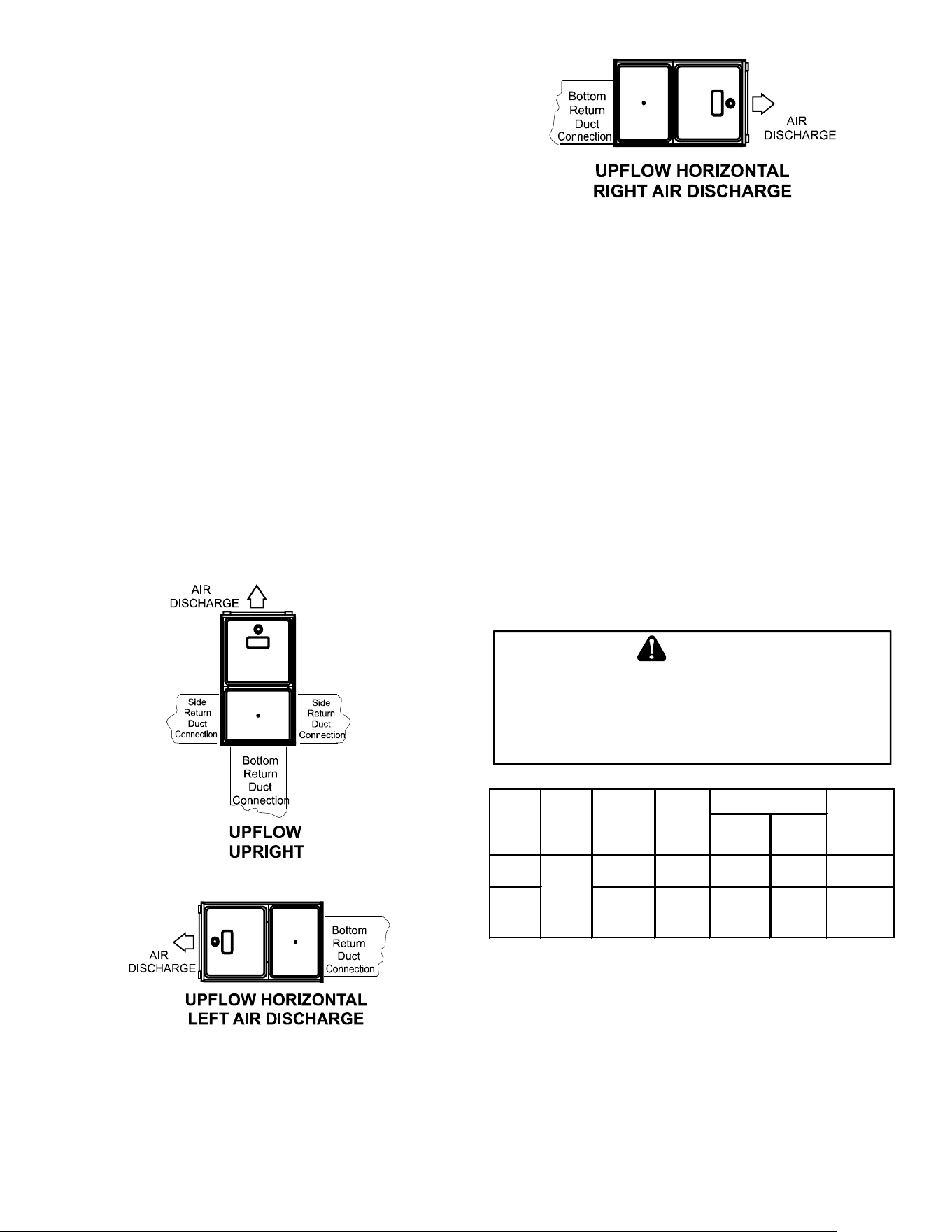
INSTALLATION POSITIONS
This furnace may be installed in an upright position or
horizontal on either the left or right side panel. Do not
install this furnace on its back. For upright upow furnaces,
return air ductwork may be attached to the side panel(s)
and/or basepan. For horizontal upow furnaces, return
air ductwork must be attached to the basepan. For
both upright or horizontal counterow furnaces, return
ductwork must be attached to the basepan (top end of
the blower compartment). NOTE: Ductwork must never
be attached to the back of the furnace. Contact your
distributor for proper airow requirements and number of
required ductwork connections. Refer to “Recommended
Installation Positions” gure for appropriate installation
positions, ductwork connections, and resulting airow
arrangements.
HORIZONTAL APPLICATIONS &
CONSIDERATIONS
2" 2" 3/8"
ANGLE
IRON
(3
PLACES
)
X X
Figure 2
When installing a furnace horizontally, additional consideration
must be given to the following:
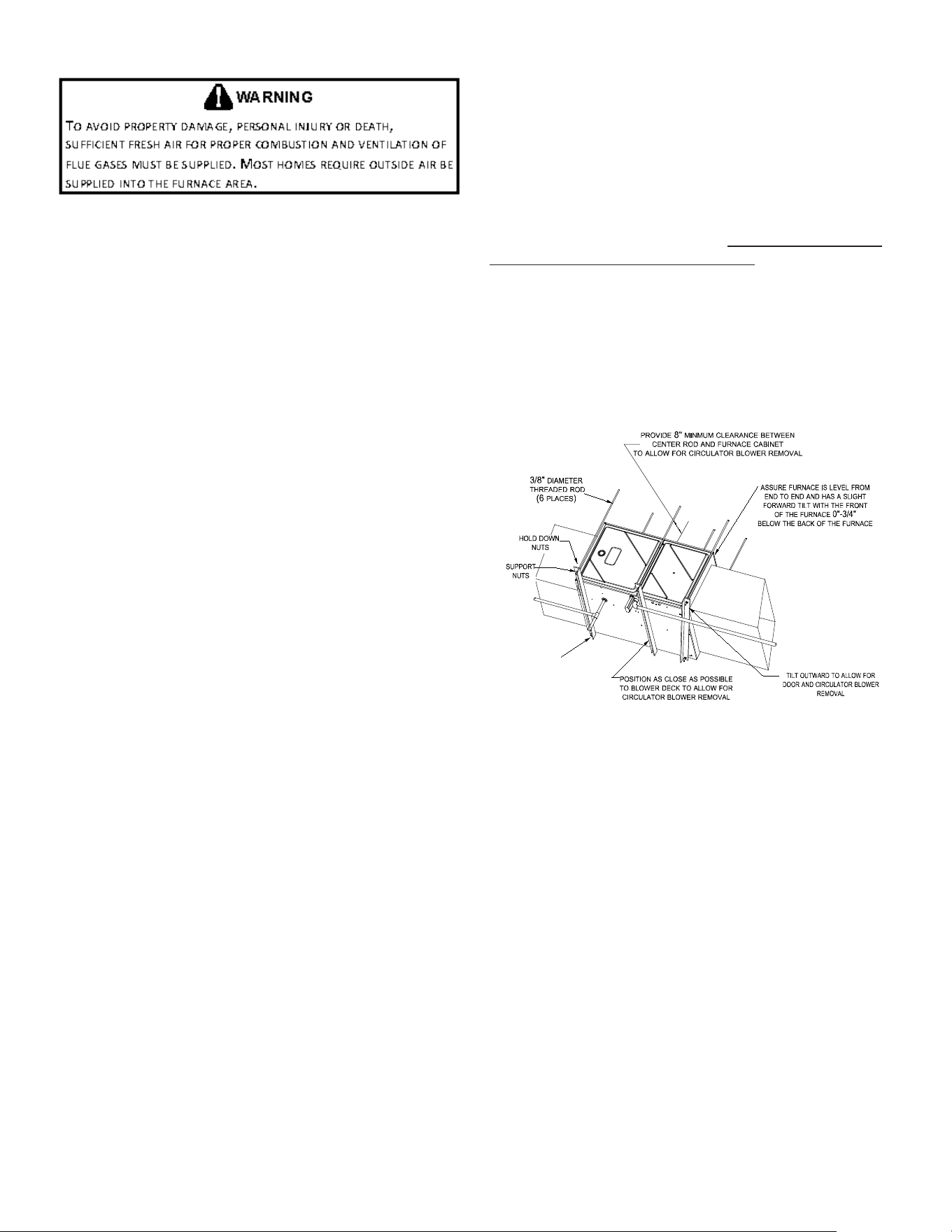
Furnace Suspension
If suspending the furnace from rafters or joists, use 3/8”
threaded rod and 2”x2”x1/8” angle iron as shown in the
following diagram. The length of rod will depend on the
application and the clearances necessary.
If the furnace is installed in a crawl space it must be
suspended from the oor joist or supported by a concrete
pad. Never install the furnace on the ground or allow it to
be exposed to water.
Front Cover Pressure Switch Tube Location
When a furnace is installed horizontally with left side down,
the front cover pressure switch tube must be re-located to
the lower port of the collector box cover.
1. Remove tube from front cover pressure switch and
collector box cover.
2. Remove rubber plug from bottom collector box port
and install on top collector box port.
12
3. Locate 24” x 1/4” tube in bag assembly.
4. Install one end on front cover pressure switch.
5. Route tube to lower port on collector box cover and
cut o excess tubing.
Drain Trap and Lines
In horizontal applications the condensate drain trap is
secured to the furnace side panel, suspending it below the
furnace. A minimum clearance of 5.5” below the furnace
must be provided for the drain trap. Additionally, the
appropriate downward piping slope must be maintained
from the drain trap to the drain location. Refer to
Condensate Drain Trap and Lines for further details. If the
drain trap and drain line will be exposed to temperatures
near or below freezing, adequate measures must be taken
to prevent condensate from freezing.
Leveling
Leveling ensures proper condensate drainage from the
heat exchanger. For proper ue pipe drainage, the furnace
must be level lengthwise from end to end. The furnace
should have a slight tilt from back to front with the access
doors downhill from the back panel approximately 1/2
to 3/4 inches. The slight tilt allows the heat exchanger
condensate, generated in the recuperator coil, to ow
forward to the recuperator coil front cover.
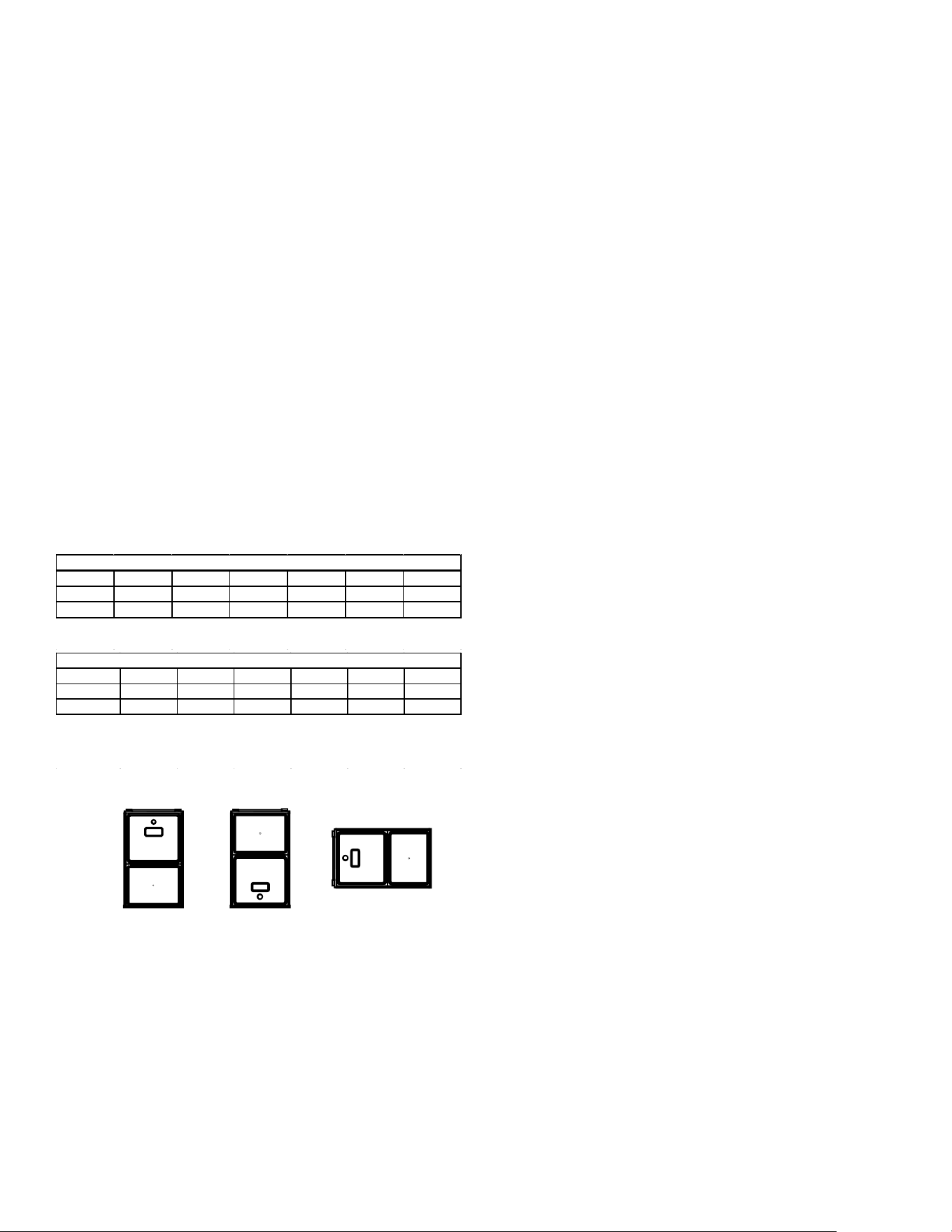
Figure 3A
Figure 3B
Figure 3C
Recommended Installation Positions
Alternate Electrical and Gas Line Connections
This furnace has provisions allowing for electrical and gas
line connections through either side panel. In horizontal
applications the connections can be made either through
the “top” or “bottom” of the furnace.
Drain Pan
A drain pan must be provided if the furnace is installed
above a conditioned area. The drain pan must cover the
entire area under the furnace (and air conditioning coil if
applicable).
Freeze Protection
If the drain line is routed through an area which may see
temperatures near or below freezing, precautions must be
taken to prevent condensate from freezing within the drain
line.
WARNING
P
OSSIBLE
PROPERTY
DAMAGE
,
PERSONAL
INJURY
OR
DEATH
MAY
OCCUR
IF
THE
CORRECT
CONVERSION
KITS
ARE
NOT
INSTALLED
. T
HE
APPROPRIATE
KITS
MUST
BE
APPLIED
TO
ENSURE
SAFE
AND
PROPER
FURNACE
OPERATION
. A
LL
CONVERSIONS
MUST
BE
PERFORMED
BY
A
QUALIFIED
INSTALLER
OR
SERVICE
AGENCY
.
High
Stage
Low
Stage
Natural None
#45 3.5" w.c. 1.9" w.c. None
Propane
LPM-07*
1
1.25mm 10.0" w.c. 6.0" w.c. None
Gas
Altitude
Kit
Orifice
Manifold Pressure
Pressure
Switch
Change
0-7000
1
LPM-07* supports both Honeywell and White-Rodgers 1-stage valves
NOTE: In Canada, gas furnaces are only certified to 4500 feet.
13
VENT PIPE & COMBUSTION AIR PIPE
U
PON
COMPLETION
OF
THE
FURNACE
INSTALLATION
,
CAREFULLY
INSPECT
THE
ENTIRE
FLUE
SYSTEM
BOTH
INSIDE
AND
OUTSIDE
OF
THE
FURNACE
TO
ASSURE
IT
IS
PROPERLY
SEALED
. L
EAKS
IN
THE
FLUE
SYSTEM
CAN
RESULT
IN
SERIOUS
PERSONAL
INJURY
OR
DEATH
DUE
TO
EXPOSURE
TO
FLUE
PRODUCTS
,
INCLUDING
CARBON
MONOXIDE
.
WARNING
F
AILURE
TO
FOLLOW
THESE
INSTRUCTIONS
CAN
RESULT
IN
BODILY
INJURY
OR
DEATH
. C
AREFULLY
READ
AND
FOLLOW
ALL
INSTRUCTIONS
GIVEN
IN
THIS
SECTION
.
WARNING
This manual will refer to the pipe that discharges products
of combustion to the outdoors as the “vent” pipe or
“ue” pipe. The pipe that supplies air for combustion
to the furnace will be referred to as the “intake” pipe or
“combustion air” pipe.
This furnace is dual certied and may be installed as a
non-direct vent (single pipe) or direct vent (dual pipe)
appliance.
MATERIALS – INSTALLATIONS IN THE
U.S.A.
PVC, CPVC, or ABS pipe & ttings are typically used as
venting and intake pipe materials. All 90° elbows must
be medium or long radius types. A medium radius elbow
should measure ~3-1/16” minimum from the plane of
one opening to the center line of the other opening for 2”
diameter pipe, and ~4-9/16” minimum for 3” pipe.
In addition to these materials, Innoue® by Centrotherm
Eco Systems and PolyPro® by M&G Duravent are
also approved vent and combustion air materials for
installations in the U.S.A. Manufacturers Installation
instructions for these products must be followed. These
products have specic instructions for installing, joining
and terminating. Do not mix materials or components of
one manufacturer with materials or components of another
manufacturer. Refer to the following chart for plastic pipe &
ttings specications.
MATERIALS – INSTALLATIONS IN CANADA
All installations in Canada must conform to the
requirements of CAN/CSA B149.1-15 code. All vent
components, including primer and cement, must be listed
to ULC S636. The certied pipe and ttings should be
clearly marked with the ULC standard “S636”. The primer
and cement used must be of the same manufacturer as
the vent system. For Royal Pipe System 636; use GVS-
65 Primer (Purple) and GVS-65 PVC Solvent Cement.
For IPEX System 636, use PVC/CPVC Primer, Purple
or clear. Use PVC Solvent cement (Gray). For Canadian
installations, ABS may be used as a combustion air pipe
only. ABS is not an approved vent material in Canada.
If ABS is used as a combustion air pipe, it must be CSA
certied. Always follow the manufacturer’s instructions
in the use of primer and cement. Do not use primer and
cement around potential sources of ignition. Do not use
primer or cement beyond its expiration date.
PVC ASTM STANDARD
SCHEDULE 40 PIPE D1785
SCHEDULE 40 CELLULAR CORE PIPE F891
SDR 21 OR 26 PIPE D2241
FITTINGS D2466
ABS
SCHEDULE 40 PIPE D1527
SCHEDULE 40 CELLULAR CORE PIPE F628
FITTINGS
D2468
CPVC
SCHEDULE 40 PIPE
F441
SDR 21 OR 26 PIPE F442
FITTINGS F438
POLYPROPYLENE
INNOFLUE® (CENTROTHERM)
POLYPRO® (DURAVENT)
PRIMER & SOLVENT CEMENT
PVC PRIMER F656
CPVC PRIMER F656
PVC SOLVENT CEMENT
D2564
CPVC SOLVENT CEMENT F493
ABS SOLVENT CEMENT D2235
ABS / PVC / CPVC ALL PURPOSE CEMENT (FOR
PIPE & FITTINGS OF THE SAME MATERIAL)
D2564, D2235, F493
TRANSITION CEMENT FOR ABS TO PVC or CPVC D3188
INSTALLATIONS IN CANADA
PVC & CPVC PIPE & FITTINGS
PVC & CPVC SOLVENT CEMENT
TRANSITION CEMENT
INNOFLUE® (CENTROTHERM)
POLYPRO® (DURAVENT)
VENTING MATERIAL REQUIREMENTS
ULC S636
14
PIPE INSTALLATION
This furnace is manufactured with 2” CPVC vent & intake
couplings. Use transition cement to connect PVC or ABS
pipe to these ttings. For furnaces requiring installation
of 3” pipe, the transition from 2” to 3” should be done as
close to the furnace as possible, and only when the piping
is sloped enough to prevent condensation from collecting.
This furnace must not be connected to Type B, BW, or
L vent or vent connector, and must not be vented into
masonry chimney. A masonry chimney may be used as
a chase or passage way for approved venting materials
providing the masonry chimney is not also being used to
vent products of combustion. Never common vent this
appliance with another appliance. Never use a vent which
is used by a solid fuel appliance.
Piping may run vertically or horizontally and must be
adequately supported to prevent strain on joints, sagging,
separation, and detachment from the furnace. Horizontal
runs of piping must be supported every three to ve
feet. Condensation within the furnace secondary heat
exchanger and in the vent pipe is a normal occurrence.
Vent pipe must be installed to maintain a minimum 1/4
inch per foot downward slope toward the furnace to return
condensate to the furnace’s drain system. Condensation
may also occur in the intake pipe. This commonly takes
place during the summer months when humid air enters
an intake pipe that runs through a cool basement or other
conditioned space. If the combustion air intake pipe is to
be installed above a nished ceiling or other area where
dripping of condensate will be objectionable, insulating
the combustion air pipe may be necessary. Use 1/2” thick
closed cell foam insulation where required. Refer to intake
pipe options for using the RF000142 kit and managing
condensation.
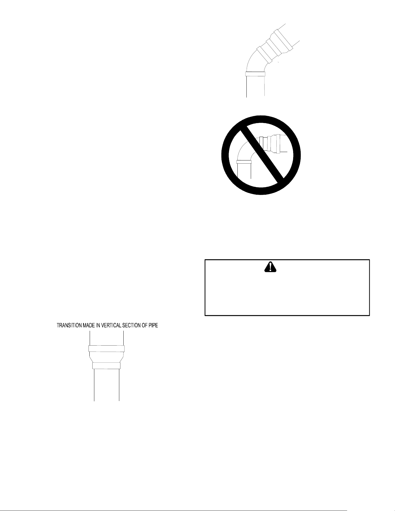
PREFERRED
Figure 4
TRANSITION NO LESS
THAN 45 DEGREES TO
HORIZONTAL PLANE TO
AVOID CREATING A WATER
TRAP IN VENT PIPING.
ACCEPTABLE
Figure 5
NO TRANSITION ON
HORIZONTAL PLANE,
THIS CREATES A
WATER TRAP AND
RESTRICTS FLUE
GASES
Figure 6
Precautions must be taken to prevent condensate from
freezing inside the vent pipe. All vent piping exposed to
freezing temperatures must be insulated with 1/2” thick
closed cell foam. Inspect piping for leaks prior to installing
insulation.
T
O
AVOID
BODILY
INJURY
,
FIRE
OR
EXPLOSION
,
SOLVENT
CEMENTS
MUST
BE
KEPT
AWAY
FROM
ALL
IGNITION
SOURCES
(
I
.
E
.,
SPARKS
,
OPEN
FLAMES
,
AND
EXCESSIVE
HEAT
)
AS
THEY
ARE
COMBUSTIBLE
LIQUIDS
.
A
VOID
BREATHING
CEMENT
VAPORS
OR
CONTACT
WITH
SKIN
AND
/
OR
EYES
.
WARNING
Pipe Sizing
Consult tables 4 & 5 to determine what diameter piping is
required for your installation. Lengths shown in the chart
apply to single pipe & two pipe installations. In a two pipe
installation the length shown refers to only one pipe, vent
or intake. Both pipes would normally be equal in length, if
dierent, then the longest pipe must be within the limits of
table 4. It is preferable to up-size from 2” to 2.5” or 3” pipe
if the pipe length & elbow count are near maximum. This
will help avoid nuisance pressure switch opening caused
by prevailing winds & sudden changes in atmospheric
pressure.
15
MODEL
PIPE
SI ZE
1 2 3 4 5 6 7 8
2 75 70 65 60 55 50 45 40
3 114 107 100 93 86 79 72 65
2 45 40 35 30 25 20 15 10
3 168 161 154 147 140 133 126 119
2 35 30 25 20 15 10 5 N/A
3 168 161 154 147 140 133 126 119
2 60 55 50 45 40 35 30 25
3 113 106 99 92 85 78 71 64
2 45 40 35 30 25 20 15 10
3 120 113 106 99 92 85 78 71
2 40 35 30 25 20 15 10 5
3 151 144 137 130 123 116 109 102
2 N/A N/A N/A N/A N/A N/A N/A N/A
3 158 151 144 137 130 123 116 109
2 100 95 90 85 80 75 70 65
3 137 130 123 116 109 102 95 88
2 45 40 35 30 25 20 15 10
3 168 161 154 147 140 133 126 119
2 40 35 30 25 20 15 10 5
3 120 113 106 99 92 85 78 71
2 N/A N/A N/A N/A N/A N/A N/A N/A
3 113 106 99 92 85 78 71 64
2 N/A N/A N/A N/A N/A N/A N/A N/A
3 110 103 96 89 82 75 68 61
*M9S960803BN - add 20' of 2" pipe for upflow position
7,000 ft altitude or above use 3" pipe
1) Maximum allow able limits listed on individual lengths for inlet and flue and NOT a
combination
2) Minimum requirement for each vent pipe is five (5) feet in length and one elbow/tee
3) Tee used in the vent/flue termination must be included when determining the number
of elbows in the piping system.
4) 2 1/2" or 3" diameter pipe can be used in place of 2" diameter pipe
Number of Elbows
*M9S960403AN
*M9S961005CN
*M9S961205DN
*M9S960603BN
*M9S960803BN
*M9S960804CN
*M9S960805CN
*C9S960403BN
*C9S960603BN
*C9S960804CN
*C9S961005CN
*C9S961205DN
Table 4
MODEL
PIPE
SI ZE
1
2 3 4 5 6 7 8
2 75 70 65 60 55 50 45 40
3 114 107 100 93 86 79 72 65
2 55 50 45 40 35 30 25 20
3 127 120 113 106 99 92 85 78
2 30 25 20 15 10 5 N/A N/A
3 72 65 58 51 44 37 30 23
2 30 25 20 15 10 5 N/A N/A
3 72 65 58 51 44 37 30 23
2 40 35 30 25 20 15 10 5
3 72 65 58 51 44 37 30 23
2 60 55 50 45 40 35 30 25
3 168 161 154 147 140 133 126 119
2 30 25 20 15 10 5 N/A N/A
3 113 106 99 92 85 78 71 64
2 N/A N/A N/A N/A N/A N/A N/A N/A
3 65 58 51 44 37 30 23 16
7,000 ft altitude or above use 3" pipe
*M9S920803BN - add 10' of 2" pipe for up flow position, add 66' of 3" pipe for up flow
position
*M9S920804CN - add 25' of 2" pipe for up flow position, add 58' of 3" pipe for up flow
position
*M9S920805CN - add 15' of 2" pipe fpr upflow position, add 58' of 3" pipe for upflow
position
1) Maxim um allow able lim its listed on individual lengths for inlet and flue and NOT a
combination
2) Minimum requirem ent for each vent pipe is five (5) fee t in length and one elbow /tee
3) Tee used in the vent/flue termination must be included when determ ining the number
of elbow s in the piping syste m .
Number of Elbows
*M9S920403AN
*M9S920603BN
*M9S920803BN
*M9S920804CN
*M9S920805CN
*M9S921004CN
*M9S921005CN
*M9S921205DN
Table 5
1. Maximum allowable limits listed on individual lengths
for inlet and ue and NOT a combination.
2. Minimum requirement for each vent pipe if ve (5)
feet in length and one elbow/tee.
3. Tee used in the vent/ue termination must be
included when determining the number of elbows in
the piping system.
4. 2 ½” or 3” diameter pipe can be used in place of 2”
diameter pipe.
5. Increased Clearance Conguration using (2) 45
deg. Long Sweep elbows should be considered
equivalent to one 90 deg. elbow.
6. One 90° elbow should be secured to the combustion
air intake connection.
Vent Pipe Connection
The vent pipe outlet is sized to accept 2” pipe. Secure vent
pipe directly into the furnace tting with the appropriate
glue. Alternately, a small section of 2” pipe may be glued
in the furnace socket and a rubber coupling installed to
allow removal for future service. Piping should be routed in
a manner to avoid contact with refrigerant lines, metering
devices, condensate drain lines, etc. If necessary,
clearances may be increased by creating an oset using
two 45° elbows (Figure 7).
45 DEGREE
ELBOWS
Increased Clearance Configuration
Figure 7
COMBUSTION AIR PIPE CONNECTION
If the furnace is being installed without a combustion air
pipe, a 90° elbow should be used on the combustion air
intake to guard against blockage.
On up ow / horizontal models, secure the combustion
air intake pipe to the air intake coupling using a rubber
coupling supplied with the furnace. The rubber coupling
may be omitted by inverting the intake coupling and gluing
pipe directly to it. Piping may also be glued to the intake
coupling in its original position by using a plastic coupling.
On counterow units secure the combustion air intake
pipe to the air intake coupling using the rubber coupling
and worm gear hose clamps provided with the unit. The
counterow rubber coupling allows service removal of air
intake piping internal to the furnace blower compartment.
The combustion air intake pipe can also be secured
directly to the counterow unit air intake pipe coupling.
16
Combustion Air Intake Options
The RF000142 coupling (Figure 9) can be secured
directly to the furnace intake coupling if condensation/
rain water is a concern. If the RF000142 is used on the
combustion air inlet, it must be installed with the arrow
pointing up. It should be noted, the combustion air will
actually be moving in a direction opposite of the arrow
on the RF000142 coupling. It must have a eld supplied,
trapped drain tube free-draining to a proper condensate
disposal location. A loop in the drain tube can serve as a
trap. The unused RF000142 drain tting must be capped.
A eld supplied tee installed in the intake pipe is also an
acceptable method of catching condensation. It must have
a eld supplied, trapped drain tube or pipe, free-draining to
a proper condensate disposal location. A loop in the drain
tube can serve as a trap.
E
DGES
OF
SHEET
METAL
HOLES
MAY
BE
SHARP
. U
SE
GLOVES
AS
A
PRECAUTION
WHEN
REMOVING
HOLE
PLUGS
.
WARNING
Alternate Vent & Intake Pipe Connections
(Upflow/Horizontal models only)
When installing a furnace horizontally with the left side
down, alternate ue and combustion air pipe connections
may be used. This method allows the ue and combustion
air piping to be run vertically through the side of the
furnace (facing up in horizontal left). The alternate vent
location is the 3” hole directly in line with the induced draft
blower outlet.
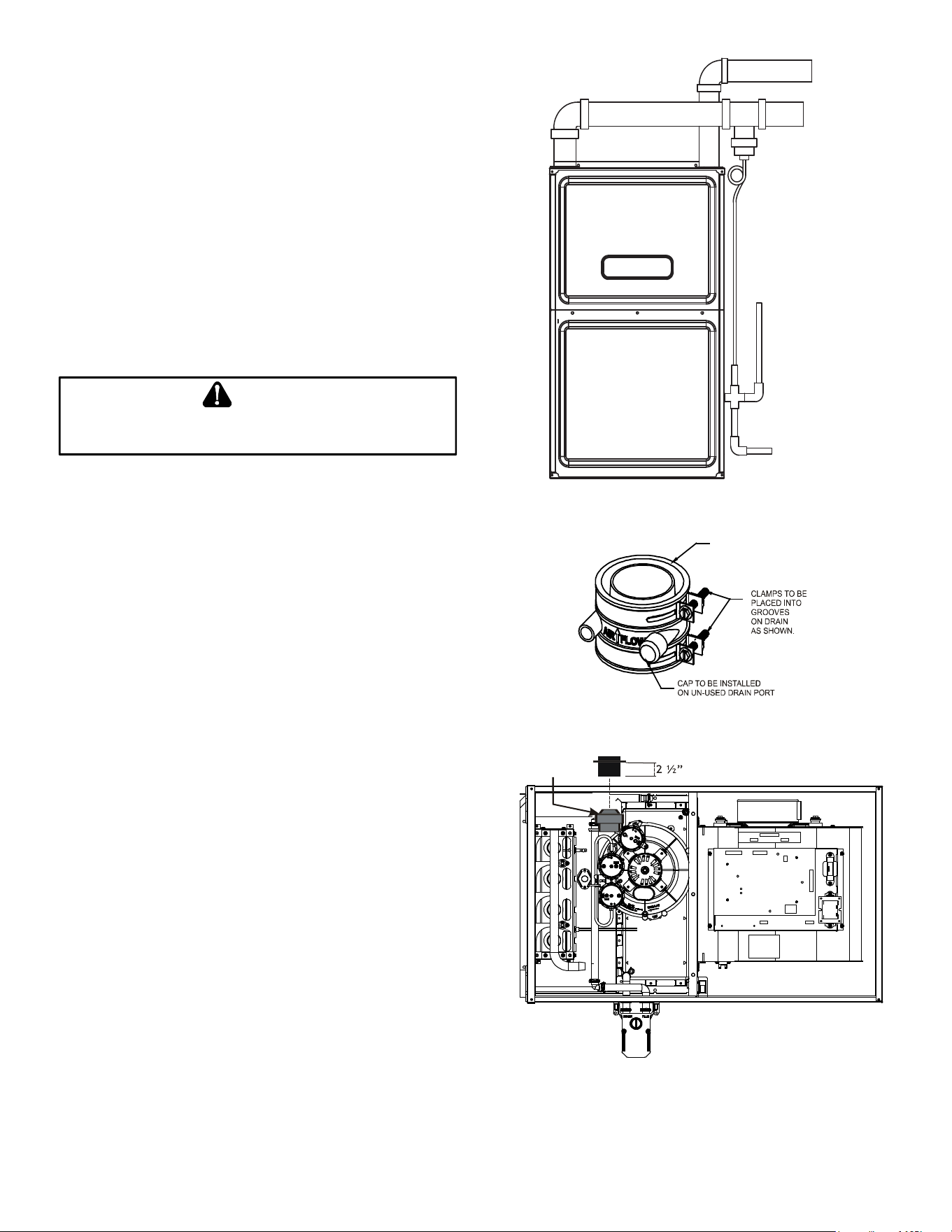
When using the horizontal alternate vent conguration,
you must use the RF000142 vent drain kit. See Figures
8-11 & follow steps below.
NOTE: In the horizontal left installation position, a
means of condensate collection must be provided
to keep vent pipe condensate from entering the draft
inducer housing. If the vent drain elbow is eliminated
from the installation, the RF000142 kit must be used.
Combustion Air
Exhaust
Tee Installation in Intake Pipe
Figure 8
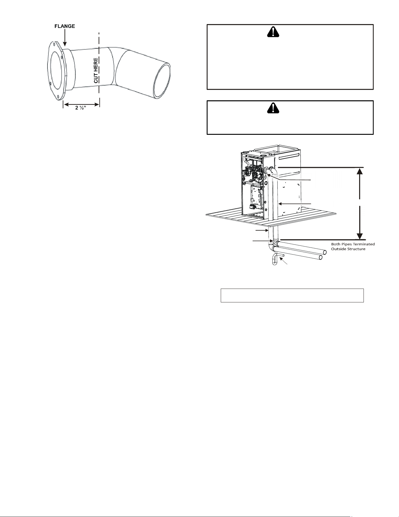
VENT-DRAIN
Figure 9
Insert flange. Cut 2 ½” long.
R 000142F
Figure 10
17
Figure 11
1. Remove the four screws from the vent pipe ange
on top the furnace.
2. Remove the internal elbow, vent pipe & gasket.
3. Cut the internal vent pipe 2 1/2” from the ange.
Discard the un-anged section.
4. Remove the 3” plastic plug (in line with the inducer
outlet) and insert it in the space vacated by removal
of the internal vent pipe.
5. Install the RF000142 drain coupling with arrow
facing up, on the draft inducer outlet.
6. Insert the 2 ½” anged section of pipe with gasket
through the 3” hole and connect to RF000142 drain
coupling. Secure it with gear clamp provided.
7. Use the four self-tapping screws removed in step 1
to secure ange to cabinet.
8. Connect drain hose to the uncapped port on the
RF000142 coupling, refer to page xx, section
entitled “Horizontal Installation with Left Side Down
– Alternate” for drain connection details
When using the alternate venting location, either in
a horizontal left side down installation or a vertical
installation using down – venting, the alternate combustion
air opening can be used. A locating dimple is located on
the right side of the furnace cabinet. The locating dimple is
1-7/8” measured from the front edge of the cabinet in line
with the knock out.
To use the alternate combustion air location:
1. Remove screws and combustion air ange and
gasket from cabinet.
2. Insert the 3” cabinet plug from the drain bag
assembly in the unused combustion air hole.
3. Drill a pilot hole at the cabinet dimple (size dictated
by knockout tool used).
4. Use a knockout tool to create a 3” diameter hole.
5. Secure the combustion air ange & gasket to the
furnace cabinet using the self-tapping screws
removed in step 1.
T
HE
RUBBER
ELBOW
IS
NOT
DESIGNED
TO
SUPPORT
A
LOAD
. W
HEN
THE
RUBBER
ELBOW
IS
MOUNTED
EXTERNALLY
TO
THE
FURNACE
CABINET
,
EXTREME
CARE
MUST
BE
TAKEN
TO
ADEQUATELY
SUPPORT
FIELD
-
SUPPLIED
VENT
/
FLUE
PIPING
,
AS
DAMAGE
CAN
RESULT
IN
LEAKS
CAUSING
BODILY
INJURY
OR
DEATH
DUE
TO
EXPOSURE
TO
FLUE
GASES
,
INCLUDING
CARBON
MONOXIDE
WARNING
B
E
SURE
NOT
TO
DAMAGE
INTERNAL
WIRING
OR
OTHER
COMPONENTS
WHEN
REINSTALLING
COUPLING
AND
SCREWS
.
CAUTION
Vent Pipe
Use alternate vent
& combination
air locations
Combustion Air Pipe
Field Supplied
Drain Tee on Vent Pipe
Condensate trapped
to prevent flue gas from escaping
and routed to field supplied
condensate disposal
1/4” per foot min.
slope to furnace
6’ Max.
Floor
B
a
s
e
m
e
n
t
/
C
r
a
w
l
s
p
a
c
e
DOWN VENTING UPFLOW MODEL FURNACES ONLY
All piping and fittings must be joined per material manufacturers specifications
to prevent separation and flue gas leaks.
Figure 12
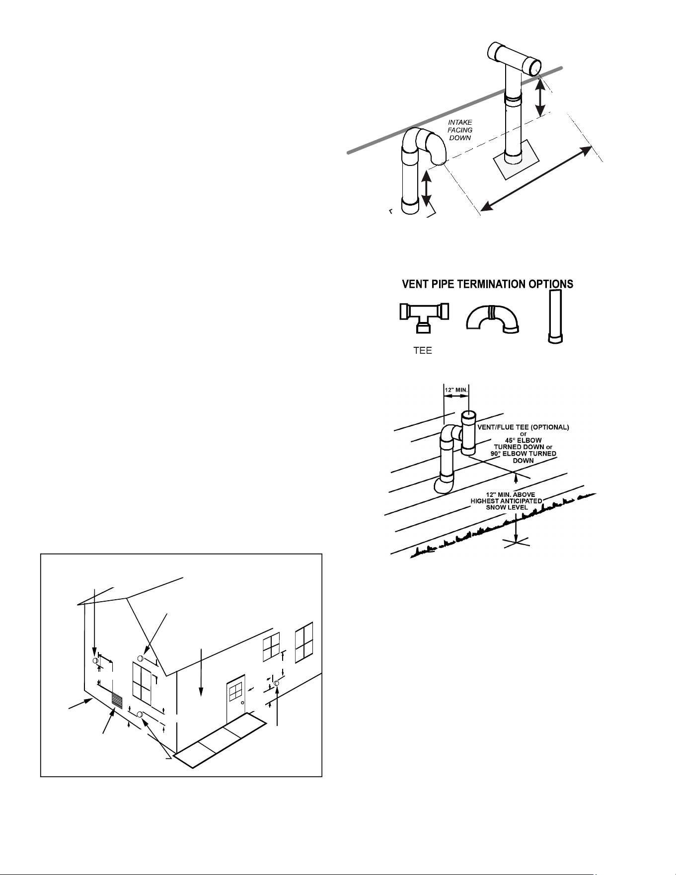
Pipe Termination
Products of combustion must always be vented outside. A
vent pipe must never terminate in an attic, crawl space, or
any other part of a dwelling. Follow the vent pipe & intake
pipe termination requirements listed below as well as all
applicable local, State and National codes.
All terminations (vent and/or intake) must be located at
least 12” above ground level or the anticipated snow level.
All vent terminations (non-direct and direct vent) must
terminate at least 3 feet above any forced air inlet located
within 10 feet.
The vent termination of a non-direct vent application must
terminate at least 4 feet below, 4 feet horizontally from, or
1 foot above any door, window, or gravity air inlet into any
building.
18
The vent termination of a direct vent application must
terminate at least 12” from any opening through which
ue gases may enter a building (door, window, or gravity
air inlet).
The vent termination of vent pipe run vertically through
a roof must terminate at least 12” above the roof line (or
the anticipated snow level) and be at least 12” from any
vertical wall (including any anticipated snow build up).
A vent termination shall not terminate over public
walkways or over an area where condensate or vapor
could create a nuisance or hazard or could be detrimental
to the operation of regulators, relief valves, or other
equipment.
The combustion air intake termination of a direct vent
application should not terminate in an area which is
frequently dusty or dirty.
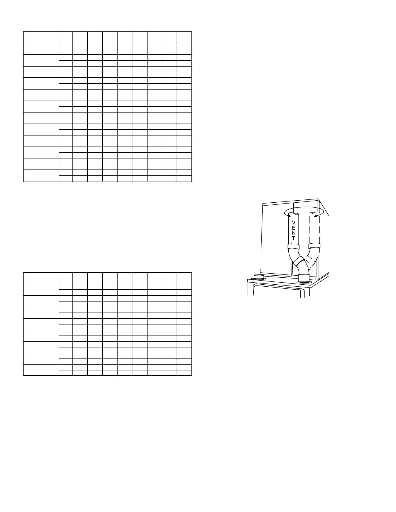
Vent & combustion air pipes may terminate vertically
through a roof, or horizontally through an outside wall.
The combustion air intake and vent pipe terminations
must be in the same atmospheric pressure zone. Vertical
vent pipe terminations should be as shown in gure 14.
The penetration of pipes through the roof must be sealed
water tight with proper ashing such as is used with a
plastic plumbing vent.
Horizontal vent pipe terminations should be as shown in
the following gures. To secure the pipe passing through
the wall and prohibit damage to piping connections, a
coupling should be installed on either side of the wall and
solvent cemented to a length of pipe connecting the two
couplings. The length of pipe should be the wall thickness
plus the depth of the socket ttings to be installed on the
inside and outside of the wall. The wall penetration should
be sealed with silicone caulking material.
12"
Non-Direct Vent
Vent/Flue Termination
No Terminations
Above Walkway
12"
min.
4'
min.
Non-Direct Vent
Vent/Flue Termination
Direct Vent
Vent/Flue Termination
<10'
Forced Air
Inlet
Non-Direct Vent
&
Direct Vent
Vent/Flue Terminations
Grade or Highest
Anticipated
Snow Level
3' min.
12" min.
4' min.
12" min.
Vent Termination Clearances
Figure 13
COMBUSTION AIR INTAKE
(OPTIONAL)
*Not required for
single pipe installation
TEE (OPTIONAL)
9
6
”
M
A
X
.
-
3
”
M
I
N
.
R
O
O
F
L
I
N
E
12” MIN
HEIGHT
DIFFERENCE
12” MIN TO ROOF OR
HIGHEST ANTICIPATED
SNOW LEVEL
Figure 14
STRAIGHT
ELBOWS
Figure 15
Horizontal Termination (Single Pipe) Above
Highest Anticipated Snow Level
Figure 16
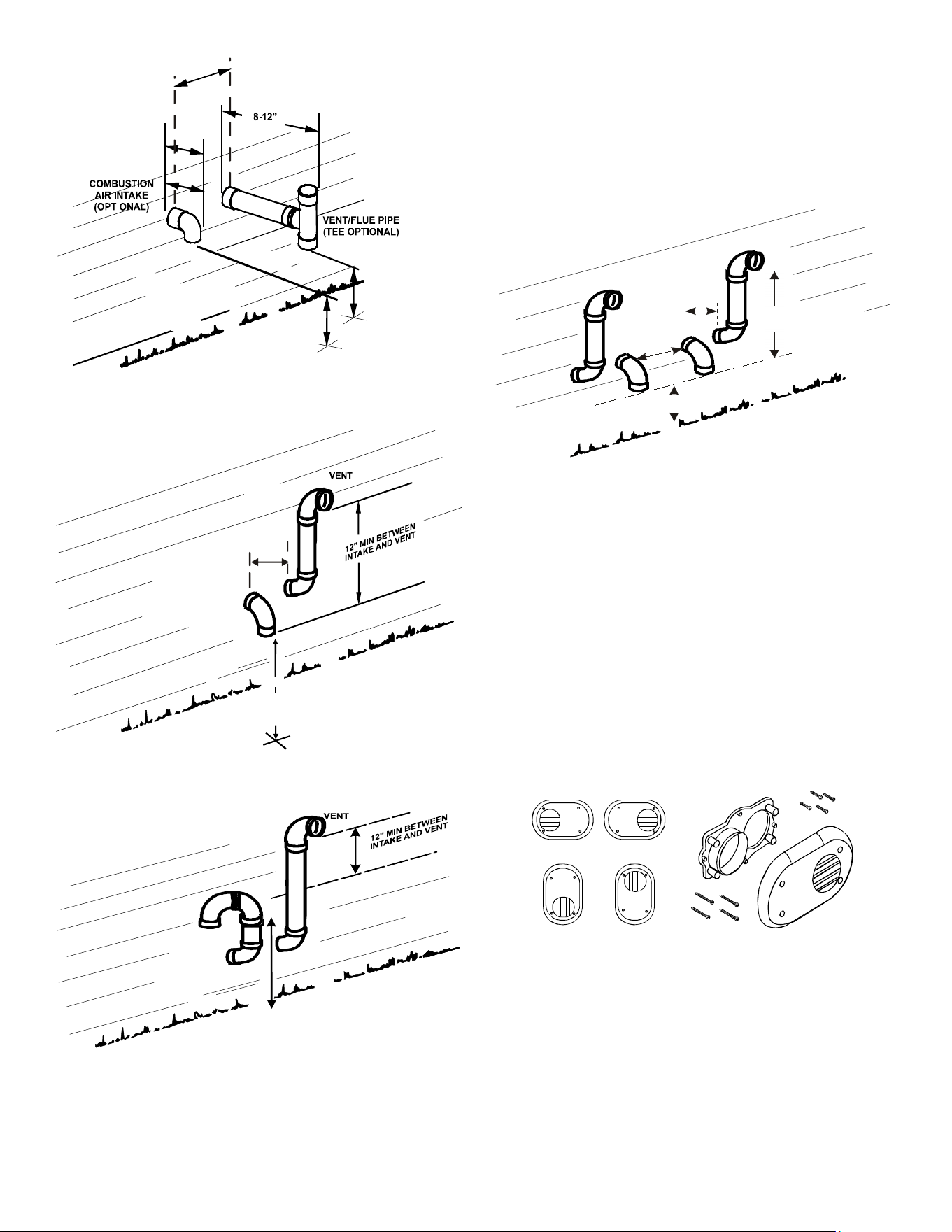
19
Vent & Combustion Air Intake Measurements for
Standard Horizontal Terminations (Dual Pipe)
Center to center = 10” min / 24” max.
Vertical separation: 0” - 24”
Vent termination from wall = 8” min / 12” max.
Combustion air intake from wall = 6” max.
Vent and intake clearance to ground or anticipated snow
level = 12” min.
3” MIN
12” MIN TO GRADE OR HIGHEST
ANTICIPATED SNOW LEVEL
3”MIN
24”MAX
12” M IN SE PARATION
Termination of Multiple Direct Vent Furnaces
Figure 20
VENT/INTAKE TERMINATIONS FOR
INSTALLATION OF MULTIPLE DIRECT VENT
FURNACES
If more than one direct vent furnace is to be installed
vertically through a common roof top, maintain the same
minimum clearances between the exhaust vent and air
intake terminations of adjacent units as with the exhaust
vent and air intake terminations of a single unit.
If more than one direct vent furnace is to be installed
horizontally through a common side wall, maintain the
clearances as in the Figure 20. Always terminate all
exhaust vent outlets at the same elevation and always
terminate all air intakes at the same elevation.
Vertical Installation
Horizontal Installation
Side Wall Vent Kit
Figure 21
Concentric Vent Termination
Refer to the directions provided with the Concentric Vent Kit or
IO-619 for installation specications.
90º OR 45°
ELBOW
12" MIN. TO GRADE OR
HIGHEST ANTICIPATED
SNOW LEVEL
6” MAX
10”- 24”
4” MIN
Standard Horizontal Terminations (Dual Pipe)
Figure 17
90°
ELBOWS
12" MIN. ABOVE
HIGHEST ANTICIPATED
SNOW LEVEL
3” - 24”
Alternate Horizontal Vent Termination (Dual Pipe)
Figure 18
90°
ELBOWS
12" MIN. ABOVE
HIGHEST ANTICIPATED
SNOW LEVEL
3”-24” BETWEEN PIPES
Combustion Air Intake may also be snorkeled
to obtain 12” min ground clearance.
Alternate Vent Termination Above Anticipated Snow
Level
(Dual Pipe)
Figure 19
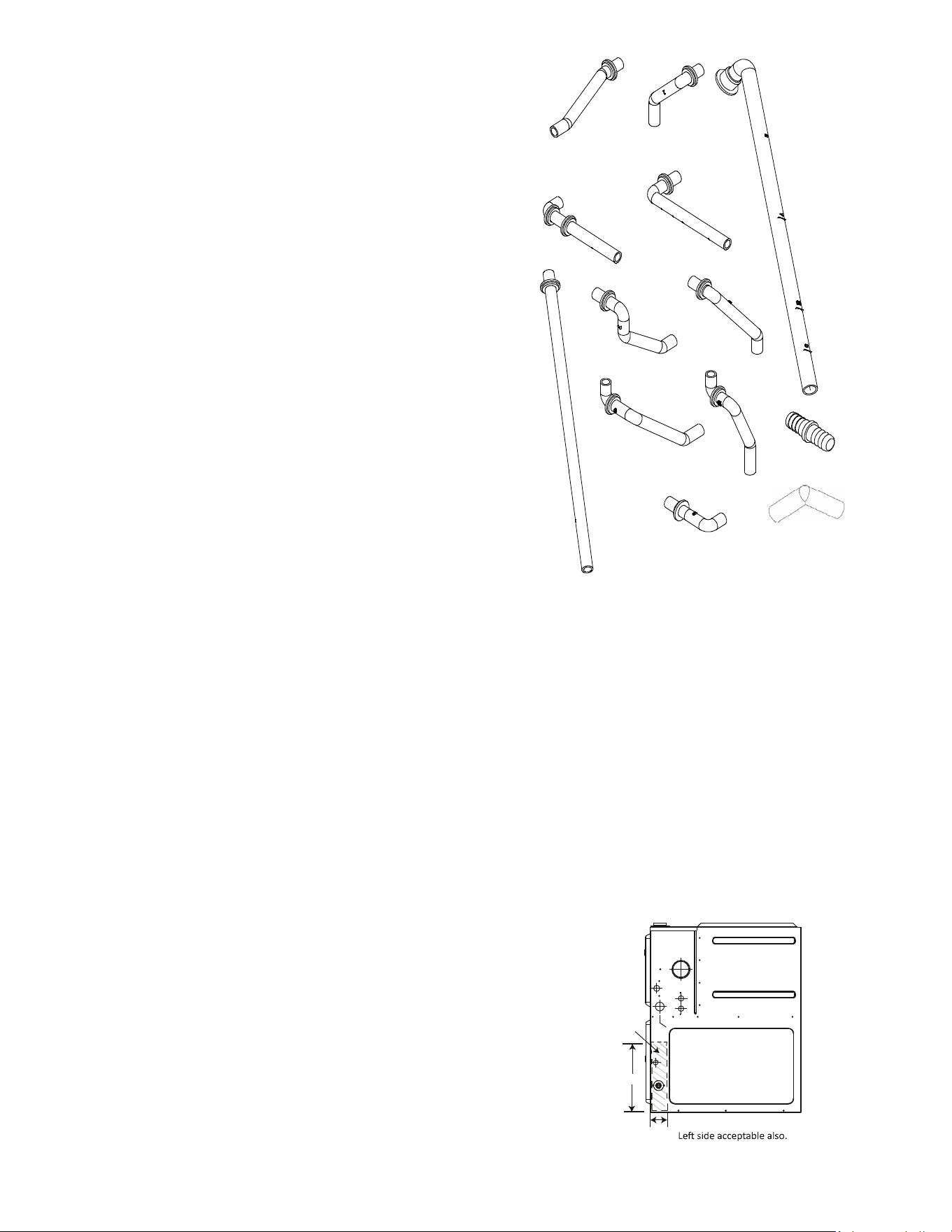
20
Side Wall Vent Kit
This kit is to be used with 2” or 3” direct vent systems. The
vent kit must terminate outside the structure and may be
installed with the intake and exhaust pipes located side-
by-side or with one pipe above the other. These kits are
NOT intended for use with single pipe (non-direct vent)
installations. Refer to the directions furnished with the
Side Wall Vent Kit (p/n 0170K00000S or 0170K00001S)
for installation specications.
CONDENSATE DRAIN LINES & DRAIN
TRAP
A condensing gas furnace achieves its high level
of eciency by extracting heat from the products of
combustion to the point where condensation takes place.
The condensate must be collected in the furnace drain trap
and routed to an appropriate drain location in compliance
with local and national codes.
Follow the bullets listed below when installing the drain
system. Refer to the following sections for specic details
concerning furnace drain trap installation and drain hose
hook ups.
• The drain trap supplied with the furnace must be used.
• The drain trap must be primed at time of installation.
• The drain line between furnace and drain location must
meet local and nation codes.
• The drain line between furnace and drain location must
maintain a 1/4 inch per foot downward slope toward the
drain.
• Do not trap the drain line in any other location than at the
drain trap supplied with the furnace.
• If the drain line is routed through an area which may see
temperatures near or below freezing, precautions must
be taken to prevent condensate from freezing within the
drain line.
• If an air conditioning coil is installed with the furnace,
a common drain may be used. An open tee must be
installed in the drain line, near the cooling coil, to relieve
positive air pressure from the coil’s plenum. This is
necessary to prohibit any interference with the function of
the furnace’s drain trap.
NOTE: In vertical installations, air conditioning coil
condensate may drain into the furnace trap as long as
there is a trap between the coil and the furnace trap
and the drain pipe is not terminating below the water
level of the furnace trap.
#
3
#1
#2
#4
#5
#
6
#7
#8
#9
#10
#11
100 Degree
Elbow
Coupling
Figure 22
NOTE: Drain components shown for information
purposes only.
General Drain Information
All furnace models come with a factory installed drain trap.
For vertical installations, the trap will remain in the factory
position except for a counterow when the installer desires
the drain to exit the right side. All furnace models installed
horizontally require the trap to be relocated. Many drain
hoses have a built–in grommet which will provide a cabinet
seal when installed. See instructions below for your model
and installation position.
NOTE: Both sides of the drain trap must be primed
prior to initial furnace start up
Side Cut-Out
12”
3”
Right side shown.
Acceptable
area for
drain hole.
Figure 23
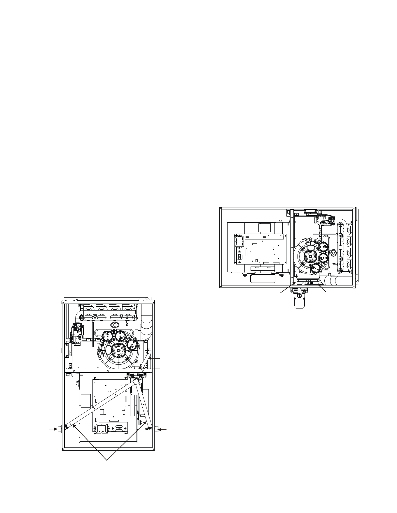
21
Field Supplied Drain
Drain the furnace and air conditioning coil if applicable,
in compliance with code requirements. In horizontal or
counterow installations, a eld installed rubber coupling
will allow the drain trap to be removed for cleaning. The
drain trap must be primed before initial furnace start up.
When an air conditioning coil drain is connected to the
eld supplied furnace drain, it must be vented. An open
tee must be installed at a height no higher than the bottom
of the furnace collector box to prevent air conditioning
condensate from backing up into the furnace, if the
common drain was blocked.
Upflow Model Installed Vertically
The trap and factory installed hoses remain as shipped.
The furnace drain may exit either the right or left side of
the furnace cabinet. Both sides of the cabinet have two
.875” diameter holes which can be used interchangeably
for drain and low voltage wiring purposes. If a higher drain
exit is needed, a .875” diameter hole may be added in the
area shown in Figure 24. Any unused cabinet opening
must be sealed. Do not allow drain hose to sag or trap
water.
Drain Exiting Right Side
1. Locate and Install the 45º pipe / hose drain coupling
from the outside of the cabinet (barbed end goes
in the cabinet) through hole in the right side of the
cabinet and secure with two eld supplied #8 self-
tapping screws (see Figure 24).
2. Locate the long drain hose #3 and cut at line “A” .
3. Install large end of hose #3 to trap outlet and secure
with 1.25” clamp.
Installer selects right or left side drain
and installs this hose accordingly.
Hose #1
Hose #2
45 degree
barb-pipe
adapter
45 degree
barb-pipe
adapter
Figure 24
4. Install smaller end of hose #3 on 45º elbow and
secure with 1” clamp.
5. Refer to Field Supplied Drain section for instructions
on eld supplied / installed drain on outlet of furnace
trap.
Drain Exiting Left Side
1. Install the 45 degree pipe / hose drain coupling
from the outside of the cabinet (barbed end goes in
the cabinet) through the hole in the left side of the
cabinet and secure with two eld supplied #8 self-
tapping screws (see Figure 24).
2. Locate the long drain hose #3 and cut at “B” line for
a 17.5” cabinet; cut at line “C” for a 21” cabinet; do
not cut for a “D” width cabinet.
3. Install large end of hose #3 to trap outlet and secure
with 1.25” clamp.
4. Install smaller end of hose #3 on 45º elbow and
secure with 1” clamp.
5. Refer to Field Supplied Drain section for instructions
on eld supplied / installed drain on outlet of furnace
trap.
Hose #11
Hose #2
Figure 25
Upflow Model Installed Horizontally with Right
Side Down
Minimum 5 1/2” clearance is required for the drain trap
beneath the furnace.
1. Remove the clamps from both ends of the drain
hoses.
2. Remove the two screws holding the drain trap to the
blower deck.
3. Remove the trap and two hoses from the blower
deck
4. Remove the two plugs from the right side of the
cabinet and install them in the blower deck.
5. (Draining the Vent Elbow ) Locate hose #2 (factory
installed) and cut 1” away from the 45 degree bend,
discard the 45 degree section. Insert hose #2 from
outside the cabinet through the cabinet drain hole
nearest the top, secure it to the barbed tting in the
elbow with a red clamp.
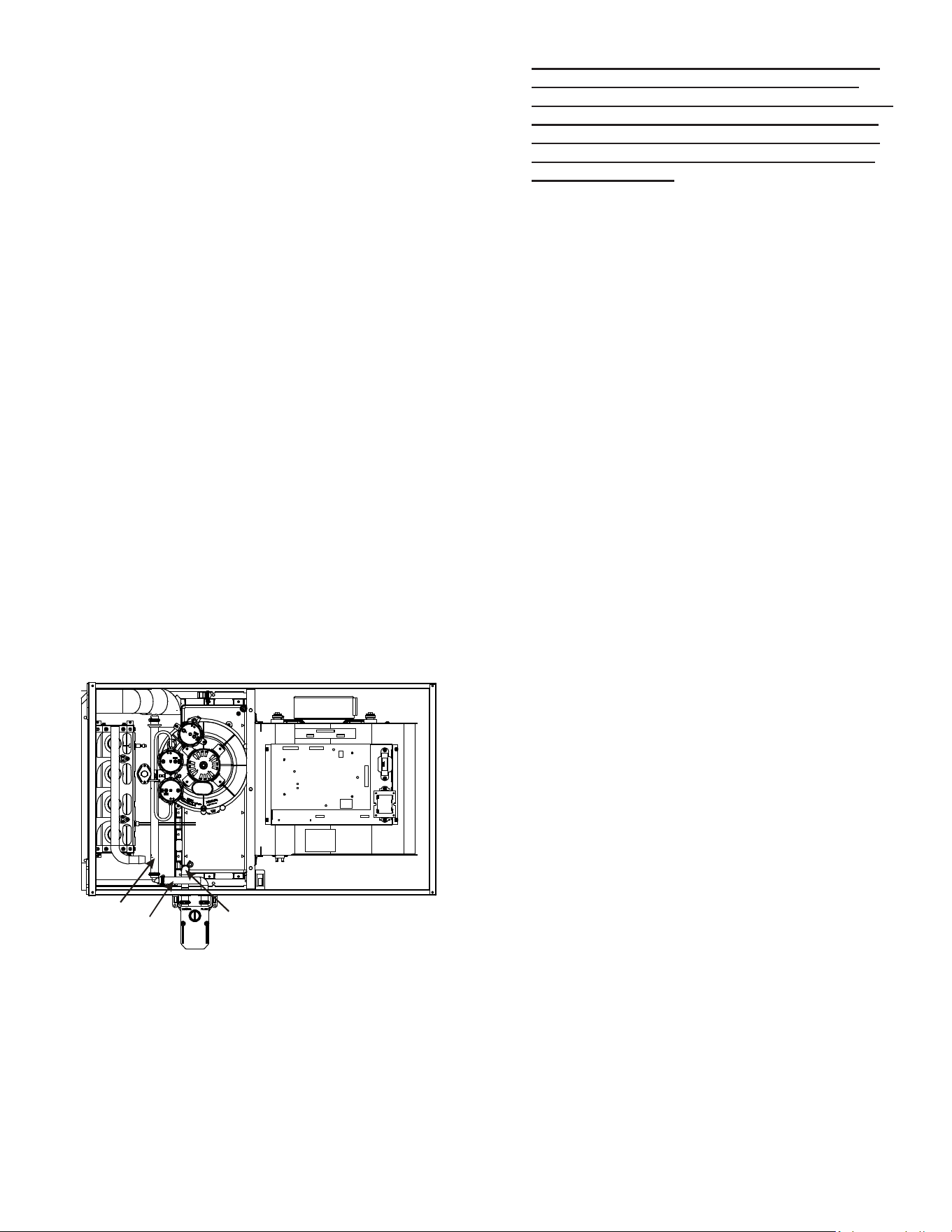
22
6. For models *MSS920403AN and *MSS960403AN;
locate the hose #2 (factory installed) and cut 1.5
length from the end of the hose. Insert hose #2 from
outside the cabinet through the cabinet’s drain hole
nearest to the top. Secure it to the barbed tting in
the elbow with a red clamp.
7. (Draining the Collector Box) Install the non-grommet
end of hose #11 from outside the cabinet in the
bottom drain hole. Install on collector box and
secure with a silver clamp.
8. Use two silver clamps and secure the hoses to drain
trap. The trap outlet faces the front of the furnace.
Secure the trap to the cabinet using two screws
removed in step 2 by inserting the two screws
through the large set of holes in the top mounting
tabs of the trap into the two pre-drilled holes in the
side of the cabinet.
9. Refer to Field Supplied Drain section for instructions
on eld supplied / installed drain on outlet of furnace
trap.
Upflow Model Installed Horizontally with Left
Side Down
Minimum 5 1/2” clearance is required for the drain trap
beneath the furnace.
*Also see Front Cover Pressure Switch Tube Location on
page 10.
1. Remove the clamps from the two drain tubes on the
trap.
2. Remove the two screws holding the drain trap to the
blower deck.
3. Remove the trap and hoses from the blower deck.
Hose #6
Hose #5
Hose #11
Figure 26
4. Remove the two plugs from the left side of the
cabinet and install them in the blower deck.
5. (Draining the Vent Elbow) Locate hose #6.
Measuring from the non-grommet end; cut o and
discard 1 ½” for a “D” width cabinet, 5” for a “C”
width cabinet, 8 ½” for a “B” width cabinet.
6. Remove the rubber plug from vent – drain elbow
side port. Place hose #6 on the vent – drain elbow
side port and secure with a silver clamp .
7. Unused vent-drain elbow drip leg port must be
sealed to prevent ue gases from escaping.
Insert the rubber plug removed in step 6 into the
unused elbow drain port. Inserting a blunt tool
such as a 3/16’’ Allen wrench into the center of
the rubber plug will stretch the plug and allow
complete insertion.
8. Locate hose #5 and cut 3” from the non-grommet
end. Discard the section without the grommet.
9. Insert the cut end of tube #5 through the lower
cabinet drain hole.
10. Connect hose #6 & hose #5 using 100º elbow and
secure with two red clamps
11. (Draining the Collector Box) Remove cap from left
side collector box drain port (bottom in horizontal left
position) and install it on right side (top) collector box
drain port.
12. Install the non-grommet end of hose #11 from
outside the cabinet in the upper drain hole. Install on
collector box and secure with a silver clamp.
13. Use two silver clamps and secure the hoses to drain
trap. The trap outlet faces the front of the furnace.
Secure the trap to the cabinet using two screws
removed in step 2 by inserting the two screws
through the large set of holes in the top mounting
tabs of the trap into the two pre-drilled holes in the
side of the cabinet. [Removed: Place cap on vent...]
14. Refer to Field Supplied Drain section for instructions
on eld supplied / installed drain on outlet of furnace
trap.
Upflow Model Installed Horizontally With Left
Side Down - Alternate
*Also see Front Cover Pressure Switch Tube Location
on Page 10.
1. (Draining the RF000142 Coupling) Locate hose #2
(factory installed). Cut o and discard the 45° radius
end.
2. Install 90°radius end of hose #2 on RF000142 drain
outlet and secure with a red clamp.
3. Insert coupling in hose #2 and secure with a red
clamp.
4. Locate hose #5 and cut 3” from the non-grommet
end. Discard the section without the grommet.
5. Insert the cut end of tube #5 through the lower
cabinet drain hole.
6. Insert 100 degree elbow in the cut end of hose #5.
7. Locate hose #6. Using red clamps, connect between
the coupling and 100 degree elbow, cutting o
excess tubing.
8. (Draining the Collector Box) Remove cap from left
side collector box drain port (bottom in horizontal left
position) and install it on right side (top) collector box
drain port and secure with a red clamp.
9. Install the non-grommet end of hose #11 from
outside the cabinet in the upper drain hole. Install on
collector box and secure with a silver clamp.
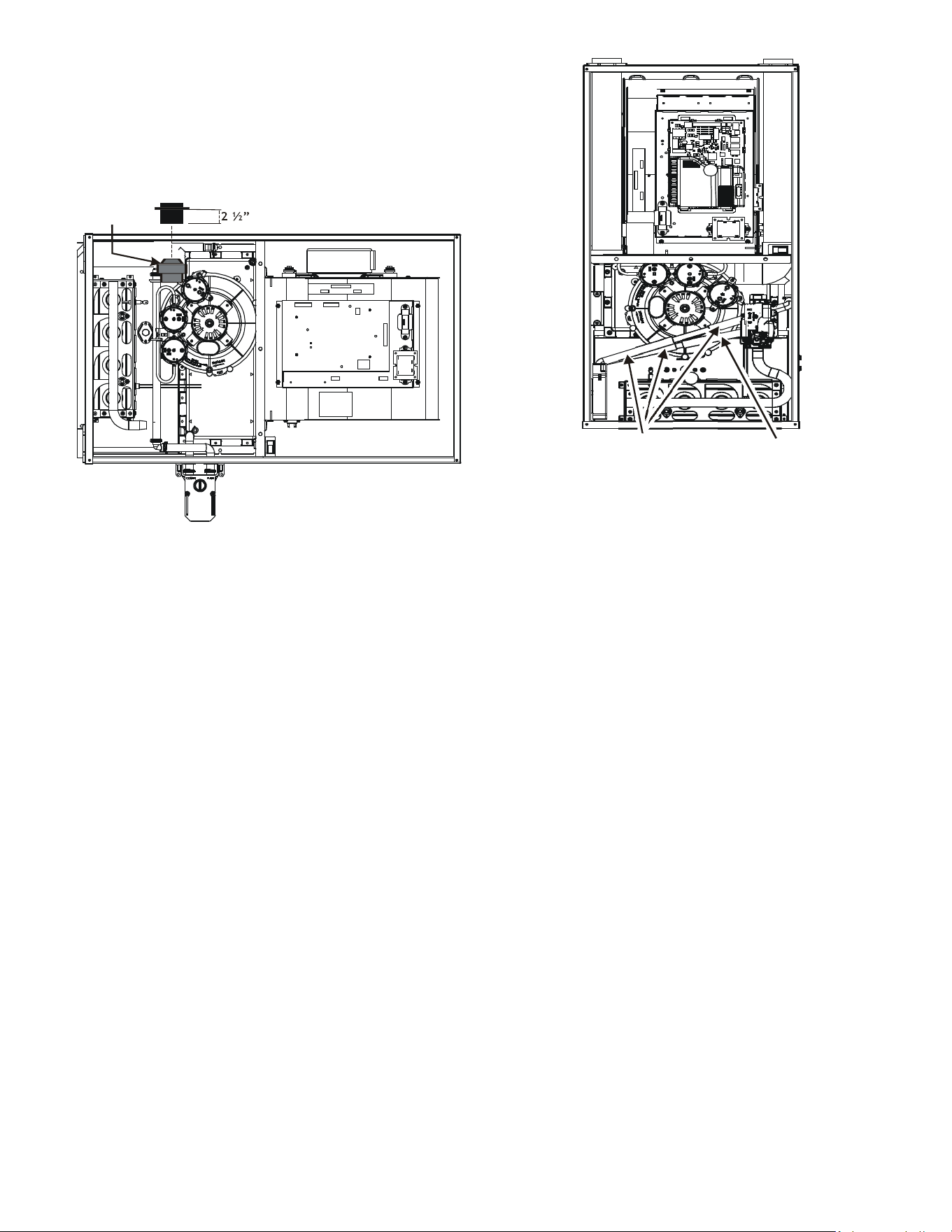
23
10. Use two silver clamps and secure the hoses to drain
trap. The trap outlet faces the front of the furnace.
Secure the trap to the cabinet using two screws
removed in step 2 by inserting the two screws
through the large set of holes in the top mounting
tabs of the trap.
Insert flange. Cut 2 ½” long.
R 000142
F
Figure 27
CounterFlow Model Installed Vertically
The furnace drain may exit the right or left side of the
furnace cabinet (left side preferred) Trap and factory
installed hoses remain as shipped if the drain will exit
the left side of the cabinet. Draining from the right side
requires relocation of the trap to outside the cabinet.
Drain Exiting Left Side (See Figure 28)
1. Install a eld supplied rubber coupling secured with
a 1 1/4” clamp to enable removing the trap for future
cleaning. Alternately, a PVC tting may be glued on
the trap outlet.
2. Install drain per local and National codes.
Hose #4 x 3
Hose #5
Figure 28
Drain Exiting Right Side (See Figure 29)
1. Removing the gas manifold assembly will provide
better access when re-locating the trap. To remove
the gas manifold, remove the four screws that fasten
the gas manifold assembly to the bracket.
2. Remove hose clamps and hoses from trap.
3. Remove trap.
4. (Draining the Vent Elbow) Insert the non-grommet
end hose #10 into the cabinet back drain hole. Insert
a coupling into the drip leg of the vent-drain elbow
and secure with a silver clamp. Secure hose #10 on
vent - drain elbow barb tting with a silver clamp.
5. (Draining the Collector Box) Insert non-grommet
end of hose #9 into the cabinet front drain hole
and secure on collector box drain port with a silver
clamp.
6. Mate the drain trap inlets to the hoses and secure
with silver clamps.
7. Line up the trap mounting holes with the pre-drilled
holes in the furnace and secure with 2 screws
removed in step 2.
8. Refer to Field Supplied Drain section for instructions
on eld supplied / installed drain on outlet of furnace
trap.
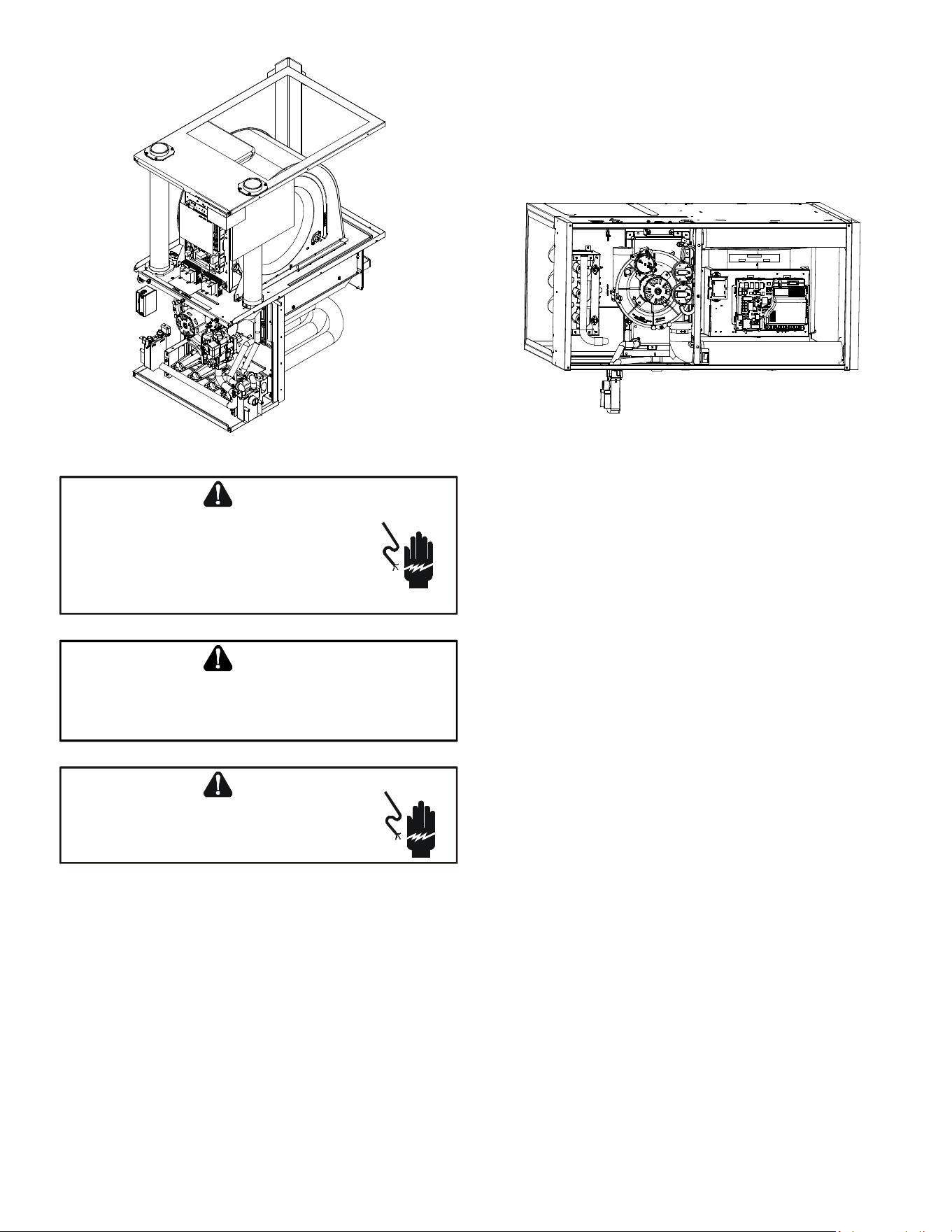
24
Figure 29
HIGH VOLTAGE !
T
O
AVOID
PERSONAL
INJURY
OR
DEATH
DUE
TO
ELECTRICAL
SHOCK
,
DISCONNECT
ELECTRICAL
POWER
BEFORE
SERVICING
OR
CHANGING
ANY
ELECTRICAL
WIRING
.
WARNING
L
ABEL
ALL
WIRES
PRIOR
TO
DISCONNECTION
WHEN
SERVICING
CONTROLS
. W
IRING
ERRORS
CAN
CAUSE
IMPROPER
AND
DANGEROUS
OPERATION
. V
ERIFY
PROPER
OPERATION
AFTER
SERVICING
.
CAUTION
HIGH VOLTAGE !
TO AVOID THE RISK OF ELECTRICAL SHOCK
, WIRING TO
THE UNIT MUST BE POLARIZED AND GROUNDED.
WARNING
Counterflow Model Installed Horizontally with
Right Side Down (See Figure 30)
Minimum 5 1/2” clearance is required for the drain trap
beneath the furnace.
NOTE: For horizontal installations, some of the
required hoses are found in the factory-installed hose
assemblies. Remove the hose clamps to obtain the
respective hoses needed for installation, and install
per the following directions.
1. Remove the drain trap and factory installed drain
tube assemblies.
2. Remove two 1’’ plugs from right side of cabinet.
3. (Draining the Collector Box) From outside the
cabinet, insert the non-grommet end hose #7 into
the back drain hole and secure to collector box drain
port using a silver clamp.
4. (Draining the Vent Elbow) Insert the straight barbed
coupling into the vent - drain elbow drip leg and
secure with a red clamp.
Figure 30
5. From outside the cabinet, insert the non-grommet
end of hose #8 into the front cabinet drain hole and
secure on the vent - drain elbow barb tting using a
red clamp.
6. Place the drain hoses on the trap inlets and secure
with silver clamps. The outlet of the trap must face
the original bottom of furnace.
7. Using the two sheet metal screws provided in the
cabinet, secure the trap to the furnace.
8. Refer to Field Supplied Drain section for instructions
on eld supplied/installed drain on outlet of furnace
trap.
Counterflow Model Installed Horizontally with
Left Side Down (See Figure 31)
Minimum 5 1/2” clearance is required for the drain trap
beneath the furnace.
*Also see Front Cover Pressure Switch Tube Location on
page 10.
1. Remove the factory installed drain trap and hose
assemblies. Leave the 100° elbow inserted and
clamped in the vent-drain elbow.
2. Remove two 1”plugs from left side of cabinet
3. (Draining the Collector Box) Remove the cap from
the left side of the collector box drain port (bottom
in horizontal left position) and install it on right side
drain port.
4. Place radius end of hose #4 (factory installed) on
the collector box drain port and secure with a silver
clamp.
5. Insert hose #2 from outside the cabinet in the front
drain hole.
6. Connect hose #4 & hose #2 together using a straight
barbed coupling and two gold clamps (factory
installed).
7. (Draining the Vent Elbow) Remove rubber plug from
vent – drain elbow side port.
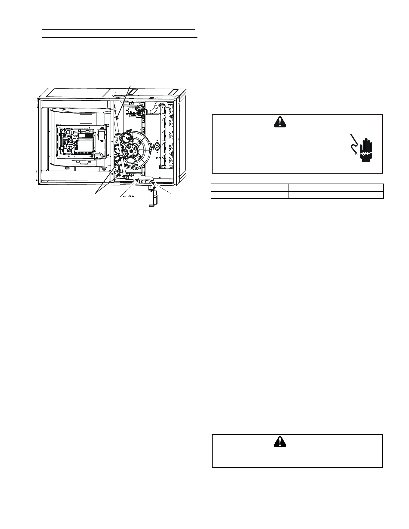
25
8. The unused vent-drain elbow drip leg port must
be plugged to prevent ue gases from escaping.
Insert rubber plug removed in step 7 into the 100°
elbow. (Inserting a blunt tool such as a 3/16’’ Allen
wrench into the center of the rubber plug will stretch
the plug and allow complete insertion)
Hose #4
Hose #5
Hose #4
Hose #2
Figure 31
9. Place radius end of hose #4 on the side port of vent
– drain elbow and secure with a gold clamp.
10. Insert a ½” diameter PVC pipe (factory installed) into
hose #4 and secure with a gold clamp.
11. Insert the non-grommet end of hose #5 (factory
installed) from outside the cabinet in the back drain
hole.
12. Insert 100º elbow in hose #5 and secure with a red
clamp.
13. Locate hose #4 and cut a cut o a 4” straight section
and discard the radius end.
14. Connect the 4” straight section of hose #4 to the
100º elbow and the PVC pipe and secure with red
clamps.
15. Connect the hoses to the trap inlets and secure
with silver clamps, drain trap outlet must point to the
original bottom of the furnace.
16. Using the two sheet metal screws provided in the
cabinet, secure the trap to the furnace.
17. Refer to Field Supplied Drain section for instructions
on eld supplied / installed drain on outlet of furnace
trap.
ELECTRICAL CONNECTIONS
Wiring Harness
The wiring harness is an integral part of this furnace.
Wires are color coded for identication purposes. Refer to
the wiring diagram for wire routings. If any of the original
wire as supplied with the furnace must be replaced, it must
be replaced with wiring material having a temperature
rating of at least 105° C. Any replacement wiring must be
a copper conductor.
115 Volt Line Connections
Before proceeding with electrical connections, ensure that
the supply voltage, frequency, and phase correspond to
that specied on the unit rating plate. Power supply to
the furnace must be NEC Class 1, and must comply with
all applicable codes. The furnace must be electrically
grounded in accordance with local codes or, in their
absence, with the latest edition of The National Electric
Code, ANSI NFPA 70 and/or The Canadian Electric Code
CSA C22.1.
HIGH VOLTAGE !
T
O
AVOID
PERSONAL
INJURY
OR
DEATH
DUE
TO
ELECTRICAL
SHOCK
,
DISCONNECT
ELECTRICAL
POWER
BEFORE
SERVICING
OR
CHANGING
ANY
ELECTRICAL
WIRING
.
WARNING
Humidifier 1.0 Amp maximum at 120 VAC
Electronic Air Cleaner 1.0 Amp maximum at 120 VAC
Use a separate fused branch electrical circuit containing
properly sized wire, and fuse or circuit breaker. The fuse
or circuit breaker must be sized in accordance with the
maximum overcurrent protection specied on the unit
rating plate. An electrical disconnect must be provided at
the furnace location.
Connect hot, neutral, and ground wires as shown in the
wiring diagram located on the unit’s blower door. Metal
conduit is not considered a substitute for an actual ground
wire to the unit. For direct vent applications, the cabinet
opening to the junction box must be sealed air tight using
either an UL approved bushing such as Heyco Liquid
Tight or by applying non-reactive UL approved sealant to
bushing.
Line polarity must be observed when making eld
connections. Line voltage connections can be made
through either the right or left side panel. The furnace
is shipped congured for a left side (right side for
counterows) electrical connection with the junction box
located inside the burner compartment. To make electrical
connections through the opposite side of the furnace, the
junction box must be relocated to the other side of the
burner compartment prior to making electrical connections.
To relocate the junction box, follow the steps shown in the
Junction Box Relocation section.
E
DGES
OF
SHEET
METAL
HOLES
MAY
BE
SHARP
. U
SE
GLOVES
AS
A
PRECAUTION
WHEN
REMOVING
HOLE
PLUGS
.
WARNING
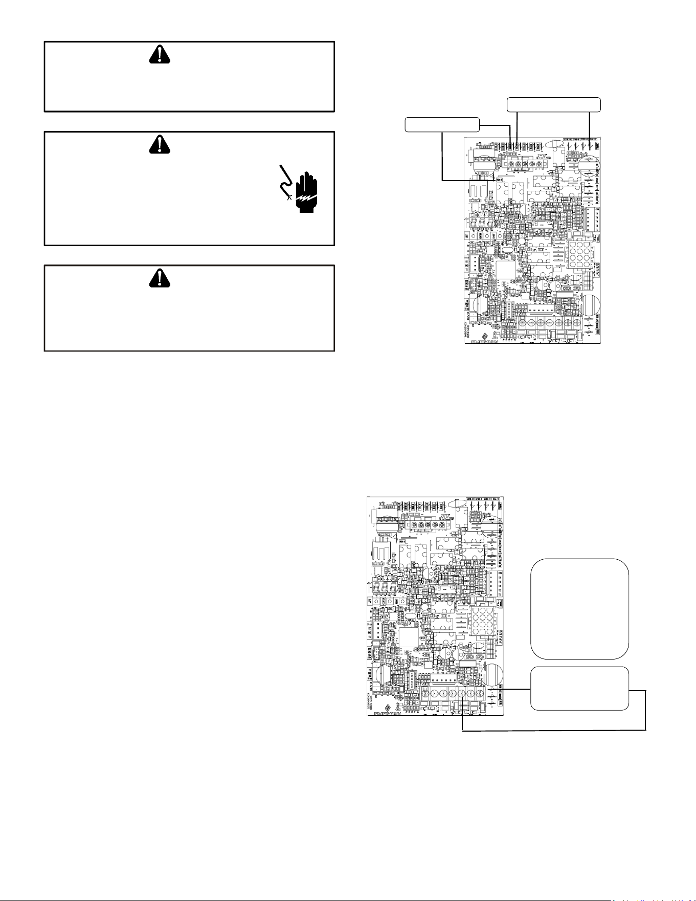
26
T
O
PREVENT
PERSONAL
INJURY
OR
DEATH
DUE
TO
ELECTRIC
SHOCK
,
DISCONNECT
ELECTRICAL
POWER
BEFORE
INSTALLING
OR
SERVICING
THIS
UNIT
.
WARNING
HIGH VOLTAGE !
T
O
AVOID
THE
RISK
OF
INJURY
,
ELECTRICAL
SHOCK
OR
DEATH
,
THE
FURNACE
MUST
BE
ELECTRICALLY
GROUNDED
IN
ACCORDANCE
WITH
LOCAL
CODES
OR
IN
THEIR
ABSENCE
,
WITH
THE
LATEST
EDITION
OF
THE
N
ATIONAL
E
LECTRIC
C
ODE
.
WARNING
WARNING
TO AVOID THE RISK OF INJURY, ELECTRICAL SHOCK OR DEATH, THE
FURNACE MUST BE ELECTRICALLY GROUNDED IN ACCORDANCE WITH
LOCAL CODES OR, IN THEIR ABSENCE, WITH THE LATEST EDITION OF THE
N
ATIONAL ELECTRICAL CODE.
115 Volt Line Voltage Connection of Accessories
(Humidifier and Electronic Air Cleaner)
The furnace integrated control module is equipped with
line voltage accessory terminals for controlling power to
an optional eld-supplied humidier and/or electronic air
cleaner.
Turn OFF power to the furnace before installing any
accessories. Follow the humidier or air cleaner
manufacturers’ instructions for locating, mounting,
grounding, and controlling these accessories. Accessory
wiring connections are to be made through the 1/4” quick
connect terminals provided on the furnace integrated
control module. The humidier hot terminal is identied
as 120V HUM-H, its neutral terminal is identied as 120V
HUM-N. The electronic air cleaner hot terminal is identied
as EAC-H, its neutral terminal is identied as 120V
EAC-N. All eld wiring must conform to applicable codes.
Connections should be made as shown. (See Figure 32)
If it is necessary for the installer to supply additional line
voltage wiring to the inside of the furnace, the wiring
must conform to all local codes, and have a minimum
temperature rating of 105°C. All line voltage wire splices
must be made inside the furnace junction box.
The integrated control module humidier terminal 120V
HUM-H is energized with 115 volts whenever the induced
draft blower is energized. This terminal can also be used
to provide 115 volt power to a humidier transformer. The
remaining primary transformer wire would be connected
to the Line N on the control board. The integrated control
module electronic air cleaner terminals EAC-H is energized
with 115 volts whenever the circulator blower is energized.
NOTE: Wire routing must not to interfere with
circulator blower operation, lter removal, or routine
maintenance.
115 VAC EAC
115 VAC HUM
W R G C Y
Figure 32
Connection of 24 Volt Humidifier
The integrated control module single humidier terminal
“24 V HUM” is energized with 24 volts whenever the
induced draft blower is energized. Connect the common
side of the 24 volt humidier to the “C” terminal of the
thermostat terminal strip on the control board.
24 VOLT HUM. &
HUMIDISTAT
W R G C Y
24V HUM Terminal is
energized when pressure
switch is closed
Figure 33
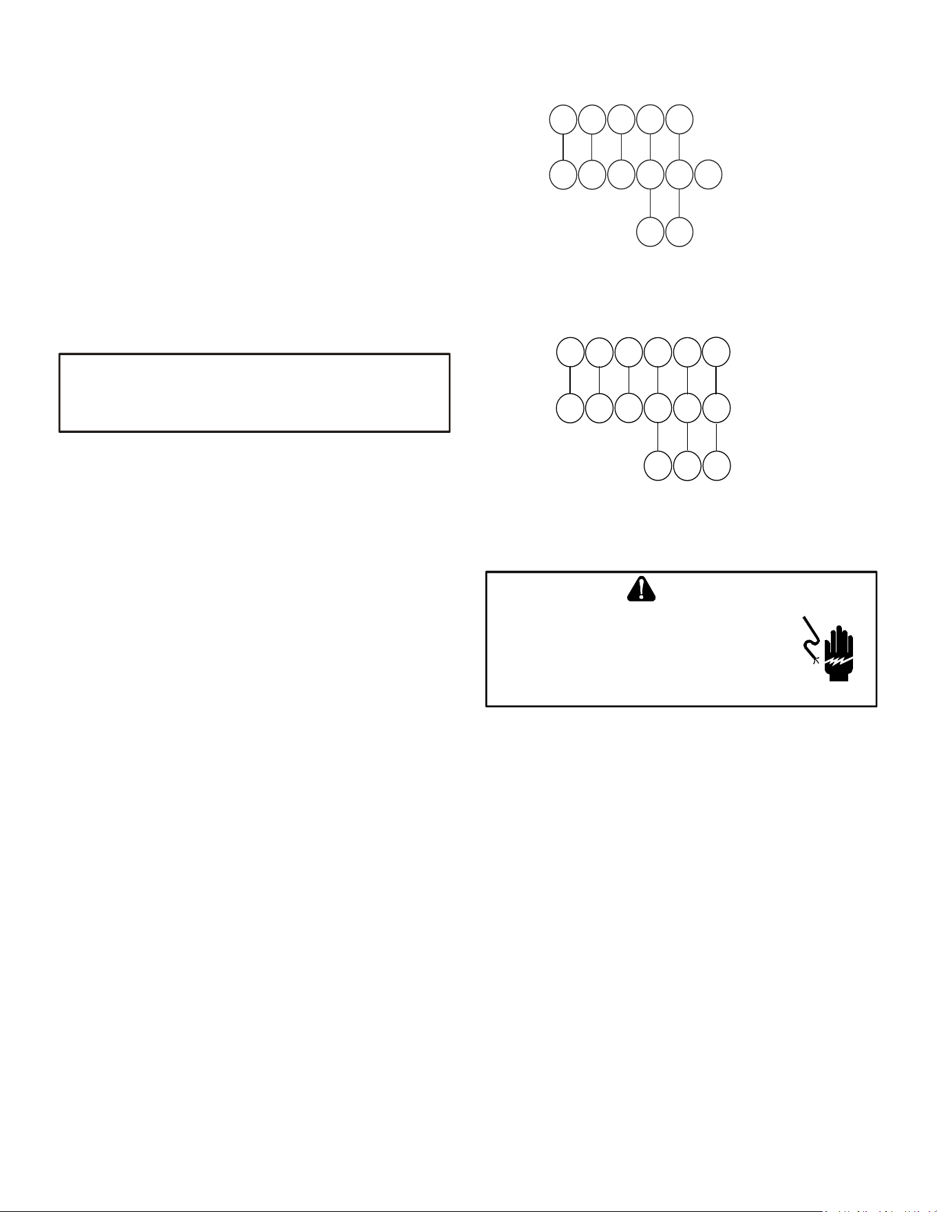
27
Junction Box Relocation
Line voltage connections can be made through either the
right or left side panel. The furnace is shipped congured
for a left side electrical connection. To make electrical
connections through the opposite side of the furnace,
the junction box must be relocated to the left side prior to
making electrical connections. To relocate the junction
box, perform the following steps.
1. Remove the burner compartment door.
2. Remove and save the two screws securing the
junction box to the side panel.
3. Relocate junction box and associated plugs and
grommets to opposite side panel. Secure with
screws removed in step.
WIRE ROUTING MUST NOT INTERFERE WITH CIRCULATOR BLOWER
OPERATION, FILTER REMOVAL OR ROUTINE MAINTENANCE.
IMPORTANT NOTE
To ensure proper unit grounding, the ground wire should
run from the furnace ground screw located inside the
furnace junction box all the way back to the electrical
panel.
NOTE: Do not use gas piping as an electrical ground.
To conrm proper unit grounding, turn o the
electrical power and perform the following check.
1. Measure resistance between the neutral (white)
connection and one of the burners.
Resistance should measure 10 ohms or less.
This furnace is equipped with a blower door interlock
switch which interrupts unit voltage when the blower door
is opened for servicing. Do not defeat this switch.
24 Volt Thermostat Wiring
Important Note: Wiring routing must not interfere with
circulator blower operation, lter removal or routine
maintenance.
Low voltage connections can be made through either the
right or left side panel. Thermostat wiring entrance holes
are located in the blower compartment. The following
gure shows connections for a “heat/cool system”.
This furnace is equipped with a 40 VA transformer to
facilitate use with most cooling equipment. Consult the
wiring diagram, located on the blower compartment door,
for further details of 115 Volt and 24 Volt wiring.
Thermostat Wiring Diagrams
Y
C
Y
C
G
R
W
Y2
Y/Y1
C
G
R
W
ROOM THERMOSTAT
INTEGRATED FURNACE
CONTROL MODULE
REMOTE COOLING UNIT
(SINGLE STAGE)
Thermostat - Single-Stage Heating with Single-
Stage Cooling
Figure 34
Y1
C
Y1C
G
R
W
Y2
Y/Y1
C
G
R
W
ROOM THERMOSTAT
INTEGRATED FURNACE
CONTROL MODULE
REMOTE COOLING UNIT
(TWO STAGE)
Y2
Y2
Thermostat - Single-Stage Heating with Two-Stage
Cooling
Figure 35
HIGH VOLTAGE !
T
O
AVOID
PERSONAL
INJURY
OR
DEATH
DUE
TO
ELECTRICAL
SHOCK
,
DISCONNECT
ELECTRICAL
POWER
BEFORE
SERVICING
OR
CHANGING
ANY
ELECTRICAL
WIRING
.
WARNING
Fossil Fuel Applications
This furnace can be used in conjunction with a heat pump
in a fossil fuel application. A fossil fuel application refers to
a combined gas furnace and heat pump installation which
uses an outdoor temperature sensor to determine the most
cost ecient means of heating (heat pump or gas furnace).
A heat pump thermostat is required to properly use a
single-stage furnace in conjunction with a heat pump.
Refer to the fossil fuel kit installation instructions for
additional thermostat requirements.
Strictly follow the wiring guidelines in the fossil fuel kit
installation instructions. All furnace connections must be
made to the furnace two-stage integrated control module
and the “FURNACE” terminal strip on the fossil fuel control
board.
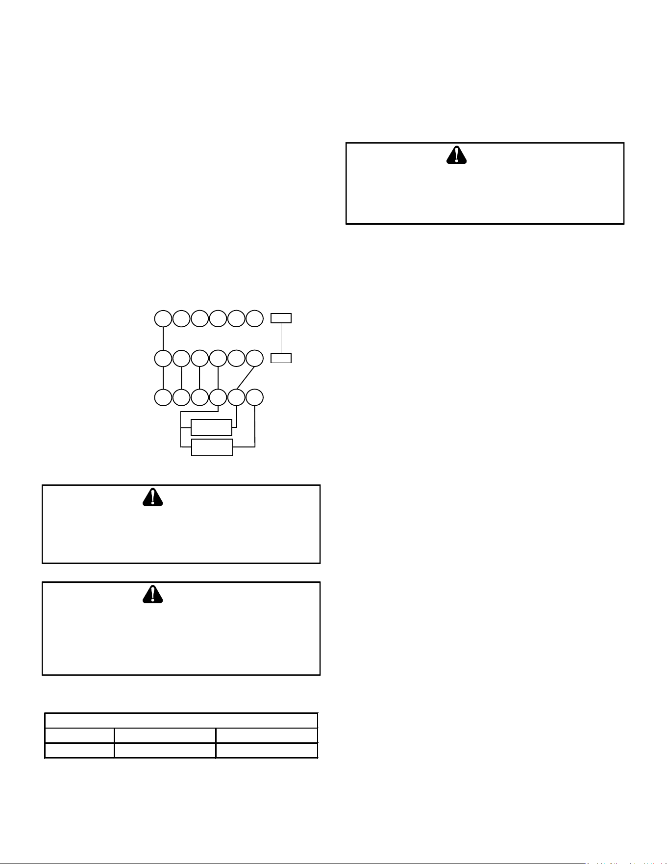
28
Inlet gas supply pressures must be maintained within
the ranges specied in the following table. The supply
pressure must be constant and available with all other
household gas red appliances operating. The minimum
gas supply pressure must be maintained to prevent
unreliable ignition. The maximum must not be exceeded
to prevent unit overring.
T
O
AVOID
POSSIBLE
UNSATISFACTORY
OPERATION
OF
EQUIPMENT
DAMAGE
DUE
TO
UNDERFIRING
OR
EQUIPMENT
,
USE
THE
PROPER
SIZE
OF
NATURAL
/
PROPANE
GAS
PIPING
NEEDED
WHEN
RUNNING
PIPE
FROM
THE
METER
/
TANK
TO
THE
FURNACE
.
WARNING
HIGH ALTITUDE INSTALLATION
When this furnace is installed at high altitude, the
appropriate High Altitude Kit including orices and a
pressure switch(s) must be installed. These changes are
necessary to compensate for the natural reduction in the
density of both the gas fuel and the combustion air at
higher altitude.
Installation of this furnace at altitudes above 7000 ft (2134
m), shall be made in accordance with the Listed High
Altitude Conversion Kit available with this furnace.
Do not de-rate the furnace by adjusting the manifold
pressure to a lower pressure than specied on the furnace
rating plate. The combination of the lower air density and
a lower manifold pressure will prohibit the burner orice
from drawing the proper amount of air into the burner. This
may cause incomplete combustion, ashback, and yellow
tipping.
In some areas the gas supplier may articially derate the
gas in an eort to compensate for the eects of altitude.
If the gas is articially derated, the appropriate orice size
must be determined based upon the BTU/ft³ content of
the derated gas and the altitude. Refer to the National
Fuel Gas Code, NFPA 54/ANSI Z223.1, and information
provided by the gas supplier to determine the proper
orice size. A dierent pressure switch may be required
at high altitude regardless of the BTU/ft³ content of the
fuel used. Consult the furnace Specication Sheet. All
conversions must be performed by a qualied installer, or
service agency.
Propane Gas Conversion
This furnace is shipped from the factory congured for
natural gas at standard altitude. To operate this furnace
on L.P. gas, a LPM-07 LP Conversion kit must be used.
Propane gas installations require an orice and spring
change to compensate for the energy content dierence
between natural and propane gas.
Twinning
Two furnaces of the same model may be twinned. The
integrated control board has a 3/16” terminal labeled
“TWIN” located beside the low voltage thermostat
connection strip. Twinning allows simultaneous operation
of two furnaces and forces the indoor blower motors of
each furnace to operate synchronously into a common
duct system. Using the twinning function will require only
eld installed wiring with no external kits or parts. The
staging and speed tap options must be set the same on
both furnaces.
NOTE: Each furnace must be connected to it’s own 115
VAC power supply. The L1 connection to each furnace
must be in phase (connected to circuit breakers on the
same 115 VAC service panel phase leg). To verify that
the furnaces are in phase, check from L1 to L1 on each
furnace with a voltmeter. If the furnaces are in phase,
the voltage between both furnaces will be ZERO.
ROOM THERMOSTAT
Y2
Y/Y1
C
G
R
W
Y2
Y/Y1
C
G
R
W
Y2
Y/Y1
C
G
R
W
TWIN
TWIN
COND UNIT
CONTACTOR
COND UNIT
CONTACTOR
FURNACE 1
FURNACE 2
Figure 36
T
O
PREVENT
UNRELIABLE
OPERATION
OR
EQUIPMENT
DAMAGE
,
THE
GAS
MANIFOLD
PRESSURE
MUST
BE
AS
SPECIFIED
ON
THE
UNIT
RATING
PLATE
. O
NLY
MINOR
ADJUSTMENTS
SHOULD
BE
MADE
BY
ADJUSTING
THE
GAS
VALVE
PRESSURE
REGULATOR
.
CAUTION
WARNING
P
OSSIBLE
PROPERTY
DAMAGE
,
PERSONAL
INJURY
OR
DEATH
MAY
OCCUR
IF
THE
CORRECT
CONVERSION
KITS
ARE
NOT
INSTALLED
. T
HE
APPROPRIATE
KITS
MUST
BE
APPLIED
TO
ENSURE
SAFE
AND
PROPER
FURNACE
OPERATION
. A
LL
CONVERSIONS
MUST
BE
PERFORMED
BY
A
QUALIFIED
INSTALLER
OR
SERVICE
AGENCY
.
GAS SUPPLY AND PIPING
Natural Gas Minimum: 4.5" w.c. Maximum: 10.0" w.c.
Propane Gas Minimum: 11.0" w.c. Maximum: 13.0" w.c.
INLET GAS SUPPLY PRESSURE
The furnace rating plate includes the approved furnace gas
input rating and gas types. The furnace must be equipped
to operate on the type of gas applied. This includes any
conversion kits required for alternate fuels and/or high
altitude.
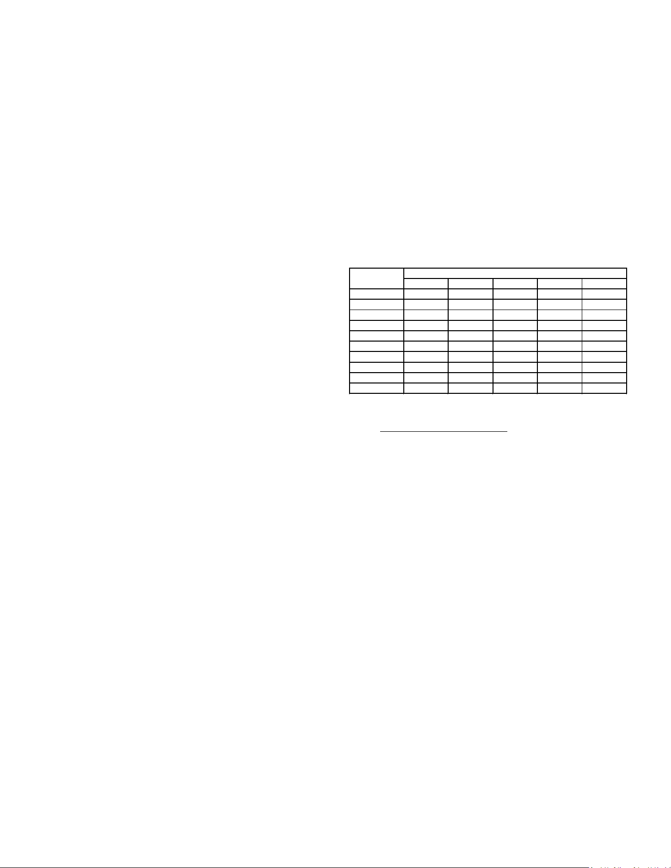
29
For furnaces being converted to LP gas, it is strongly
recommended that a LPLP03 kit also be installed. The
use of this kit will prevent the furnace from ring when
the LP gas supply pressure is too low to support proper
combustion.
All conversions must be performed by a qualied installer,
or service agency.
Gas Valve
This unit is equipped with a 24 volt gas valve controlled
during furnace operation by the integrated control
module. As shipped, the valve is congured for natural
gas. The valve is eld convertible for use with propane
gas by replacing the regulator spring with a propane
gas spring from an appropriate manufacturer’s propane
gas conversion kit. Taps for measuring the gas supply
pressure and manifold pressure are provided on the valve.
The gas valve has a manual ON/OFF control located on
the valve itself. This control may be set only to the “ON”
or “OFF” position. Refer to the lighting instructions label
or Startup Procedure & Adjustment for use of this control
during start up and shut down periods.
Gas Piping Connections
The gas piping supplying the furnace must be properly sized
based on the gas ow required, specic gravity of the gas, and
length of the run. The gas line installation must comply with
local codes, or in their absence, with the latest edition of the
National Fuel Gas Code, NFPA 54/ANSI Z223.1 or CAN/CSA
B149.1-15 in Canada.
To connect the furnace to the building’s gas piping, the
installer must supply a ground joint union, drip leg, manual
shuto valve, and line and ttings to connect to gas valve.
In some cases, the installer may also need to supply a
transition piece from 1/2” pipe to a larger pipe size.
The following stipulations apply when connecting gas
piping. Refer to Gas Piping Connections gure for typical
gas line connections to the furnace.
• Gas piping must be supported external to the furnace
cabinet so that the weight of the gas line does not
distort the burner rack, manifold or gas valve.
• Use black iron or steel pipe and ttings for building
piping. Where possible, use new pipe that is properly
chamfered, reamed, and free of burrs and chips. If
old pipe is used, be sure it is clean and free of rust,
scale, burrs, chips, and old pipe joint compound.
• Use pipe joint compound on male threads ONLY.
Always use pipe joint compound (pipe dope) that
is APPROVED FOR ALL GASES. DO NOT apply
compound to the rst two threads.
• Use ground joint unions.
• Install a drip leg to trap dirt and moisture before it can
enter the gas valve. The drip leg must be a minimum
of three inches long.
• Install a 1/8” NPT pipe plug tting, accessible for test
gauge connection, immediately upstream of the gas
supply connection to the furnace.
• Always use a back-up wrench when making the
connection to the gas valve to keep it from turning.
The orientation of the gas valve on the manifold must
be maintained as shipped from the factory. Maximum
torque for the gas valve connection is 375 in-lbs;
excessive over-tightening may damage the gas valve.
• Install a manual shuto valve between the gas
meter and unit within six feet of the unit. If a union
is installed, the union must be downstream of the
manual shuto valve, between the shuto valve and
the furnace.
• Tighten all joints securely.
Natural Gas Capacity of Pipe
In Cubic Feet of Gas Per Hour (CFH)
Length of Nominal Black Pipe Size
Pipe in Feet 1/2" 3/4" 1" 1 1/4" 1 1/2"
10 132 278 520 1050 1600
20 92 190 350 730 1100
30 73 152 285 590 980
40 63 130 245 500 760
50 56 115 215 440 670
60 50 105 195 400 610
70 46 96 180 370 560
80 43 90 170 350 530
90 40 84 160 320 490
100 38 79 150 305 460
(Pressure 0.5 psig or less and pressure drop of 0.3" W.C.; Based on
0.60 Specific Gravity Gas)
CFH =
BTUH Furnace Input
Heating Value of Gas (BTU/Cubic Foot)
• Connection method must be in compliance with all
local and national codes. US: National Fuel Gas
Code (NFGC) NFPA 54-2012/ANSI Z223.1-2012 and
the Installation Standards, Warm Air Heating and Air
Conditioning Systems ANSI/NFPA 90B.
In Canada, CANADA: National Standard of Canada,
Natural Gas and Propane Installation Code
(NSCNGPIC) CSA B149.1-15.
Connect the furnace to the building piping by one of
the following methods:
─ Rigid metallic pipe and ttings.
─ Semi-rigid metallic tubing and metallic ttings.
Aluminum alloy tubing must not be used in
exterior locations. In order to seal the grommet
cabinet penetration, rigid pipe must be used to
reach the outside of the cabinet. A semi-rigid
connector to the gas piping may be used from
there.
• Use listed gas appliance connectors in accordance
with their instructions. Connectors must be fully in
the same room as the furnace.
• Protect connectors and semi-rigid tubing against
physical and thermal damage when installed. Ensure
aluminum-alloy tubing and connectors are coated to
protect against external corrosion when in contact
with masonry, plaster, or insulation, or subjected to
repeated wetting by liquids such as water (except rain
water), detergents, or sewage.
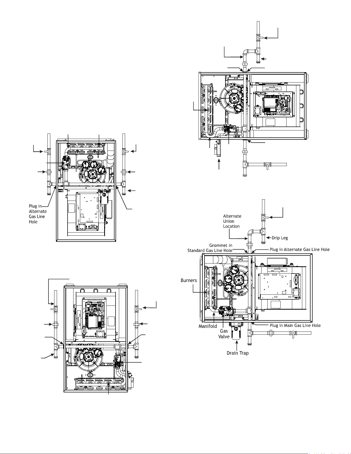
30
The gas piping may enter the left or right side of the
furnace cabinet. The installer must supply rigid pipe long
enough to reach the outside of the cabinet to seal the grommet
cabinet penetration. A semi-rigid connector to the gas piping
can be used outside the cabinet per local codes. 1/2” NPT
pipe and ttings are required. For models with an “L”
shaped manifold, a 4 1/2” long nipple is required. For
models with a hook shaped manifold, a 2” long nipple is
required.
A semi-rigid connector to the gas piping can be used
outside the cabinet per local codes. From the elbow, the
length of pipe and the ttings required will vary by the side
chosen, location of union and cabinet width. The union
may be placed inside or outside of the cabinet.
Alternate
Gas Line
Location
Gas Valve
Burners
Manual Shut Off Valve
(upstream from
ground joint
pipe union)
Drip Leg
Grommet
in Standard
Gas Line
Hole
*Ground
Joint
Pipe
Union
*Ground
Joint
Pipe
Union
*NOTE: Union may be inside furnace cabinet where allowed by local codes.
Manifold
UPFLOW
Figure 37
Alternate
Gas Line
Location
Plug in
Alternate
Gas Line
Hole
Gas Valve
Burners
Manual Shut Off Valve
(upstream from ground joint pipe union)
Drip Leg
Grommet
in Standard
Gas Line
Hole
*Ground
Joint
Pipe Union
*Ground
Joint
Pipe Union
*NOTE: Union may be inside furnace cabinet where allowed by local codes.
COUNTERFLOW
Figure 38
Drip Leg
Plug in Main Gas Line Hole
Alternate
Union
Location
Manual Shut Off Valve
(upstream from
ground joint pipe union)
Gas
Valve
Burners
Drain Trap
Manifold
Plug in Alternate Gas Line Hole
Grommet in
Standard Gas Line Hole
UPFLOW - HORIZONTAL LEFT
Figure 39
Manual Shut Off Valve
(upstream from
ground joint
pipe union)
COUNTERFLOW - HORIZONTAL RIGHT
Figure 40
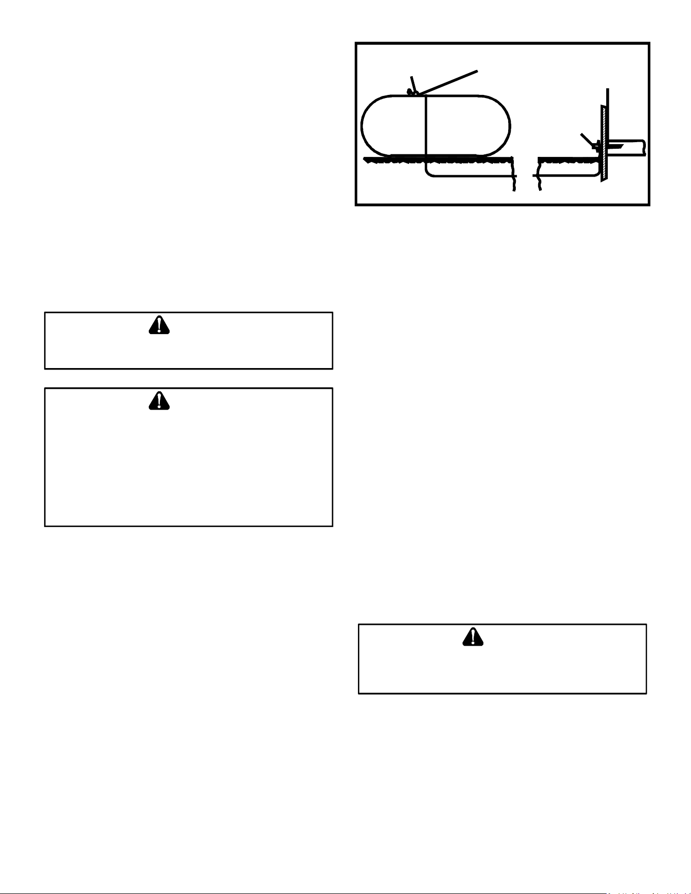
31
Gas Piping Checks
Before placing unit in operation, leak test the unit and gas
connections.
Check for leaks using an approved chloride-free soap and
water solution, an electronic combustible gas detector, or
other approved testing methods.
NOTE: Never exceed specied pressures for testing.
Higher pressure may damage the gas valve and cause
subsequent overring, resulting in heat exchanger
failure.
Disconnect this unit and shuto valve from the gas supply
piping system before pressure testing the supply piping
system with pressures in excess of 1/2 psig (3.48 kPa).
Isolate this unit from the gas supply piping system by closing
its external manual gas shuto valve before pressure testing
supply piping system with test pressures equal to or less than
1/2 psig (3.48 kPA).
T
O
AVOID
THE
POSSIBILITY
OF
EXPLOSION
OR
FIRE
,
NEVER
USE
A
MATCH
OR
OPEN
FLAME
TO
TEST
FOR
LEAKS
.
WARNING
I
F
THE
GAS
FURNACE
IS
INSTALLED
IN
A
BASEMENT
,
AN
EXCAVATED
AREA
OR
CONFINED
SPACE
,
IT
IS
STRONGLY
RECOMMENDED
TO
CONTACT
A
PROPANE
SUPPLIER
TO
INSTALL
A
GAS
DETECTING
WARNING
DEVICE
IN
CASE
OF
A
GAS
LEAK
.
S
INCE
PROPANE
GAS
IS
HEAVIER
THAN
AIR
,
ANY
LEAKING
GAS
CAN
SETTLE
IN
ANY
LOW
AREAS
OR
CONFINED
SPACES
.
P
ROPANE
GAS
ODORANT
MAY
FADE
,
MAKING
THE
GAS
UNDETECTABLE
EXCEPT
WITH
A
WARNING
DEVICE
.
•
•
WARNING
Propane Gas Tanks and Piping
A gas detecting warning system is the only reliable way
to detect a propane gas leak. Rust can reduce the level
of odorant in propane gas. Do not rely on your sense
of smell. Contact a local propane gas supplier about
installing a gas detecting warning system. If the presence
of gas is suspected, follow the instructions listed in the
Safety Considerations section of this manual.
All propane gas equipment must conform to the safety
standards of the National Board of Fire Underwriters,
NBFU Manual 58.
CANADA: National Standard of Canada, Natural Gas and
Propane Installation Code (NSCNGPIC) CSA B149.1-15.
200 PSIG
Maximum
5 to 15 PSIG
(20 PSIG Max.)
Continuous
11" W.C.
Second Stage
Regulator
First Stage
Regulator
Propane Gas Installation (Typ.)
Figure 41
For satisfactory operation, propane gas pressure must be
10” WC at the furnace manifold with all gas appli ances in
operation. Maintaining proper gas pressure depends on
three main factors:
1. Vaporization rate, depending on temperature of the
liquid, and “wetted surface” area of the con tainer or
containers.
2. Proper pressure regulation. (Two-stage regulation is
recommended for both cost and eciency).
3. Pressure drop in lines between regulators, and
between second stage regulator and the appliance.
Pipe size will depend on length of pipe run and total
load of all appliances.
Complete information regarding tank sizing for vaporiza-
tion, recommended regulator settings, and pipe sizing is
available from most regulator manufacturers and propane
gas suppliers.
Since propane gas will quickly dissolve white lead and
most standard com mercial compounds, special pipe dope
must be used. Always use a pipe thread sealant approved
for all gases.
Refer to the illustration for typical propane gas
installations and piping.
N
EVER
ALLOW
THE
PRODUCTS
OF
COMBUSTION
,
INCLUDING
CARBON
MONOXIDE
,
TO
ENTER
THE
RETURN
DUCT
WORK
OR
CIRCULATION
AIR
SUPPLY
.
WARNING
CIRCULATING AIR & FILTERS
Duct work - Air Flow
Duct systems and register sizes must be properly
designed for the CFM and external static pressure rat ing
of the furnace. Design the ductwork in accor dance with the
recommended methods of “Air Conditioning Contractors
of America” Manual D.
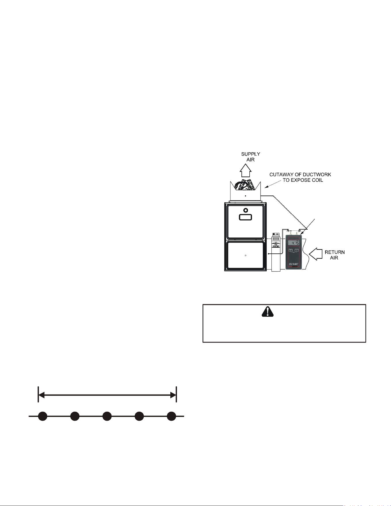
32
Install the duct system in accordance with Standards of
the National Board of Fire Underwriters for the Installation
of Air Conditioning, Warm Air Heating and Ventilating
Systems. Pamphlets No. 90A and 90B.
A closed return duct system must be used, with the return
duct connected to the furnace. NOTE: Ductwork must
never be attached to the back of the furnace. For upow
installations requiring 1800 CFM or more, use either two
side returns or bottom return or a combination of side /
bottom. Flexible joints may be used for supply and return
con nections to reduce noise transmission. To prevent the
blower from inter fering with combustion air or draft when a
central return is used, a connecting duct must be installed
between the unit and the utility room wall. Never use a
room, closet, or alcove as a return air chamber.
Checking Duct Static
Refer to your furnace rating plate for the maximum ESP
(external duct static) rating.
Total external static refers to everything external to the
furnace cabinet. Cooling coils, lters, ducts, grilles,
registers must all be considered when reading your total
external static pressure. The supply duct pressure must
be read between the furnace and the cooling coil. This
reading is usually taken by removing the “A” shaped block
o plate from the end on the coil; drilling a test hole in
it and reinstalling the block o plate. Take a duct static
reading at the test hole. Tape up the test hole after your
test is complete. The negative pressure must be read
between the lter and the furnace blower.
Too much external static pressure will result in insucient
air that can cause excessive temperature rise. This can
cause limit switch tripping and heat exchanger failure.
To determine total external duct static pressure, proceed
as follows;
1. With clean lters in the furnace, use a manometer to
measure the static pressure of the return duct at the
inlet of the furnace. (Negative Pressure)
2. Measure the static pressure of the supply duct.
(Positive Pressure)
3. The dierence between the two numbers is .4” w.c.
Example:
-1
0
1 2
3
Difference is 4
Static reading from return duct = -.1” w.c.
Static reading from supply duct = .3” w.c.
Total external static pressure on this system = .4” w.c.
NOTE: Both readings may be taken simultaneously
and read directly on the manometer if so desired. If an
air conditioner coil or Electronic Air Cleaner is used in
conjunction with the furnace, the readings must also
include theses components, as shown in the following
drawing.
4. Consult proper tables for the quantity of air.
If the total external static pressure exceeds the maximum
listed on the furnace rating plate, check for closed
dampers, registers, undersized and/or oversized poorly
laid out duct work.
The temperature rise of the furnace must be within the
temperature rise range listed on the furnace rating plate.
Digital
Manometer
Checking Static Pressure
(80% Furnace Shown, 90% Similar)
Figure 42
E
DGES
OF
SHEET
METAL
HOLES
MAY
BE
SHARP
. U
SE
GLOVES
AS
A
PRECAUTION
WHEN
REMOVING
SHEET
METAL
FROM
RETURN
AIR
OPENINGS
.
WARNING
Bottom Return Air Opening [Upflow Models]
The bottom return air opening on upow models utilizes
a “lance and cut” method to remove sheet metal from the
duct opening in the base pan. To remove, simply press
out the lanced sections by hand to expose the metal strips
retaining the sheet metal over the duct opening. Using
tin snips, cut the metal strips and remove the sheet metal
covering the duct opening. In the corners of the opening,
cut the sheet metal along the scribe lines to free the duct
anges. Using the scribe line along the duct ange as a
guide, unfold the duct anges around the perimeter of the
opening using a pair of seamer pliers or seamer tongs.
NOTE: Airow area will be reduced by approximately
18% if duct anges are not unfolded. This could cause
performance issues and noise issues.
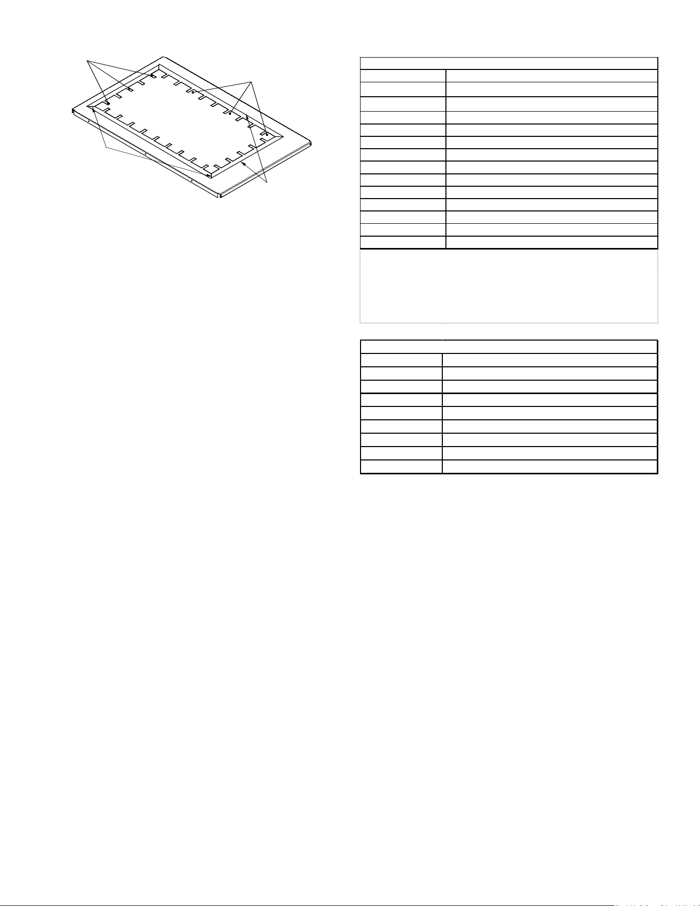
33
CUT FOUR CORNERS
AFTER REMOVING SHEET
METAL
CUT USING TIN SNIPS
PRESS OUT BY HAND
SCRIBE LINES OUTLINING
DUCT FLANGES
Duct Flange Cut Outs
Figure 43
When the furnace is used in connection with a cooling unit,
the furnace should be installed in parallel with or on the
upstream side of the cooling unit to avoid condensa tion
in the heating element. With a parallel ow arrange ment,
the dampers or other means used to control the ow of
air must be adequate to prevent chilled air from entering
the furnace and, if manually operated, must be equipped
with means to prevent operation of either unit unless the
damper is in the full heat or cool position.
When the furnace is installed without a cooling coil, it is
recommended that a removable access panel be provided
in the outlet air duct. This opening shall be accessible
when the furnace is installed and shall be of such a size
that the heat exchanger can be viewed for visual light
inspection or such that a sampling probe can be inserted
into the air stream. The access panel must be made to
prevent air leaks when the furnace is in operation.
When the furnace is heating, the temperature of the return
air entering the furnace must be between 55°F and 100°F.
FILTERS - READ THIS SECTION BEFORE
INSTALLING THE RETURN AIR DUCT
WORK
Filters must be used with this furnace. Discuss lter
maintenance with the building owner. Filters do not ship
with this furnace, but must be provided, sized and installed
externally by the installer. Filters must comply with UL900
or CAN/ULCS111 standards. Damage or repairs due to
the installation of the furnace without lters is not covered
under the warranty.
On upow units, guide dimples locate the side return
cutout locations. Use a straight edge to scribe lines
connecting the dimples. Cut out the opening on these
lines. NOTE: An undersized opening will cause reduced
airow.
Refer to the Filter Sizing Chart to determine lter area
requirements.
Filter Sizing Charts
Model Minimum Recommended Filter Size
*M9S960403AN
1 - 16 X 25 Side or 1 - 14 X 24 Bottom Return
*M9S960603BN
1 - 16 X 25 Side or Bottom Return
*M9S960803BN 1 - 16 X 25 Side or Bottom Return
*M9S960804CN
1 - 16 X 25 Side or Bottom Return
*M9S960805CN 2 - 16 X 25 Side or 1 - 20 X 25 Bottom Return
*M9S961005CN 2 - 16 X 25 Side or 1 - 20 X 25 Bottom Return¹
*M9S961205DN 2 - 16 X 25 Side or 1 - 24 X 24 Bottom Return¹
*C9S960403BN 2 - 10 X 20 or 1 - 14 X 25 Top Return
*C9S960603BN 2 - 10 X 20 or 1 - 14 X 25 Top Return
*C9S960804CN
2 - 14 X 20 or 1 - 16 X 25 Top Return
*C9S961005CN 2 - 14 X 20 or 1 - 20 X 25 Top Return
*C9S961205DN 2 - 14 X 20 or 1 - 24 X 24 Top Return
Filter Sizing Chart
Larger filters may be used, filters may also be centrally located.
¹ = use 2 - 16 X 25 filters and two side returns or 20 X 25 filter on
bottom return or combination side & bottom if furnace is connected to
a cooling unit over 4 tons nominal capacity
Model Minimum Recommended Filter Size
*M9S920403AN 1 - 16 X 25 Side or 1 - 14 X 24 Bottom Return
*M9S920603BN 1 - 16 X 25 Side or Bottom Return
*M9S920803BN 1 - 16 X 25 Side or Bottom Return
*M9S920804CN 1 - 16 X 25 Side or Bottom Return
*M9S920805CN 2 - 16 X 25 Side or 1 - 20 X 25 Bottom Return
*M9S921004CN 1 - 16 X 25 Side or Bottom Return
*M9S921005CN 2 - 16 X 25 Side or 1 - 20 X 25 Bottom Return¹
*M9S921205DN 2 - 16 X 25 Side or 1 - 24 X 24 Bottom Return¹
Filter Sizing Chart
Larger filters may be used, filters may also be centrally located.
¹ = use 2 - 16 X 25 filters and two side returns or 20 X 25 filter on
bottom return or combination side & bottom if furnace is
connected to a cooling unit over 4 tons nominal capacity
Change filters before occupants
take ownership of a new home!
Consider installing an air cleaner with deep-pleated media
lter at the time of furnace installation. A deep-pleated
lter with a MERV rating of 8 (minimum) will often provide
better ltration to protect equipment and the air distribution
system than a standard 1” lter and often has lower static
pressure loss than a 1” lter. Also a deep-pleated lter
will typically require less frequent replacement intervals.
Avoid using highly restrictive 1” lters which produce static
pressure loss greater than .25” W.C. In some installations
the minimum lter size required (consult lter sizing chart
above) will not lend itself to a lter installation on the side
of the furnace. The installation of a centrally installed air
cleaner cabinet or a return duct lter installation may oer
more practicality.
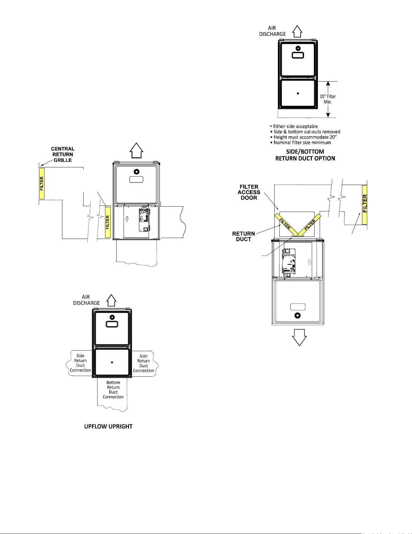
34
Clean Comfort™ brand MERV 11 air cleaners have
5¼” media lters and are available in the following
congurations. Consult your distributor for information on
our complete line of IAQ Clean Comfort™ products.
Depending on the installation and/or customer preference,
diering lter arrangements can be applied. Filters can
be installed in the central return register or a side panel
external lter rack kit (upows). As an alternative a media
air lter or electronic air cleaner can be used as the
requested lter.
The following gures show possible lter locations:
AIR FLOW
SIDE RETURN
EXTERNAL FILTER
RACK KIT
(EITHER SIDE)
Possible Upright Upflow
Figure 44
Figure 45
Figure 46
AIR FLOW
CENTRAL
RETURN
GRILLE
FILTE R
SUPPORT
BRACKET
(Field Supplied)
Possible Upright Counterflow
Filter Locations
Figure 47
Horizontal Installations
Filters must be installed in either the central return register
or in the return air duct work.

35
STARTUP PROCEDURE & ADJUSTMENT
Furnace must have a 115 VAC power supply properly
connected and grounded. Proper polarity must be
maintained for correct operation. In addition to the
following start-up and adjustment items, refer to further
information in Operational Checks section.
Furnace Cabinet
Check that all furnace cabinet sealing components are in
place (plugs, grommets, gaskets). NOTE; If the furnace
bottom panel has not been removed for a return duct
connection, all perforations must be sealed with duct
sealant compound or other suitable method to prevent air
leakage. For optimal performance verify that all do gaskets
are properly in place and replace as needed to prevent air
leakage.
Drain Trap Priming
The drain trap must be primed prior to furnace startup.
To prime, ll both sides of the drain trap with water.
This ensures proper furnace drainage upon startup and
prohibits the possibility of ue gases escaping through the
drain system.
Furnace Operation
Purge gas lines of air prior to startup. Be sure not purge
lines into an enclosed burner compartment. Follow
NFPA 54, National Fuel Gas Code 8.1 for proper purging
methods. In Canada, follow approved purging methods in
B149.1-15.
Check for leaks using an approved chloride-free soap and
water solution, an electronic combustible gas detector,
or other approved method. Verify that all required kits
(propane gas, high altitude, etc.) have been appropriately
installed.
Furnace Startup
1. Close the manual gas shuto valve external to the
furnace.
2. Turn o the electrical power to the furnace.
3. Set the room thermostat to the lowest possible
setting.
4. Remove the burner compartment door.
NOTE: This furnace is equipped with an ignition
device which automatically lights the burner. Do not
try to light the burner by hand.
5. Move the furnace gas valve manual control to the
OFF position.
6. Wait ve minutes then smell for gas. Be sure check
near the oor as some types of gas are heavier than
air.
7. If you smell gas after ve minutes, immediately
follow the safety instructions in the Safety
Considerations on page 2 of this manual. If you do
not smell gas after ve minutes, move the furnace
gas valve manual control to the ON position.
8. Replace the burner compartment door.
9. Open the manual gas shuto valve external to the
furnace.
10. Turn on the electrical power to the furnace.
11. Adjust the thermostat to a setting above room
temperature.
12. After the burners are lit, set the thermostat to desired
temperature.
Gas Heat Sequence of Operation
Call for Heat
• On a call for heat, the thermostat contacts close & the
control board receives 24 VAC on the W terminal.
• The control board microcomputer runs its self-check
routine.
• The control veries the limit switch is closed (24 VAC
on Pin 8 of the 12 Pin connector).
• The control veries that pressure switch circuit is
open (0 VAC on Pin 5).
• The control module performs a gas valve circuitry
check to verify gas valve relay state and presence of
voltage at the valve.
• The system will energize the Induced draft blower.
• The pre-purge period begins once the pressure
switch is detected closed (24 VAC on Pin 5).
• After the completion of pre-purge, the control will
energize the igniter.
• After completion of the ignitor warm-up period:
• The gas valve is energized.
• The ignitor is de-energized as soon as ame is
sensed.
• After 30 seconds the indoor blower is energized on
heating speed.
• When the thermostat is satised:
• The gas valve is de-energized.
• The inducer remains energized for the post purge
period (15 seconds).
• The indoor blower runs for the selected o delay
period (90 seconds by default, adjustable from 30 –
180 seconds).
Heating Mode Speed Selection
To change the main blower speed in HEATING mode,
follow the following steps:
1. Press left or right button till LED displays “gA1 “(for
single stage HEATING). Press center button and
LED will display the selected speed number as Fxx
(xx: Blower speed number).
2. The control shall rotate available speed number
every time Left/Right switches are pressed. Table
below shows the available speeds for Low & High
heat mode.
3. When the center switch is pressed, the current
displayed speed shall be selected, and control shall
apply the newly selected speed in next heating call.
NOTE: Always refer to the Heating Chart to choose from
available heating speeds
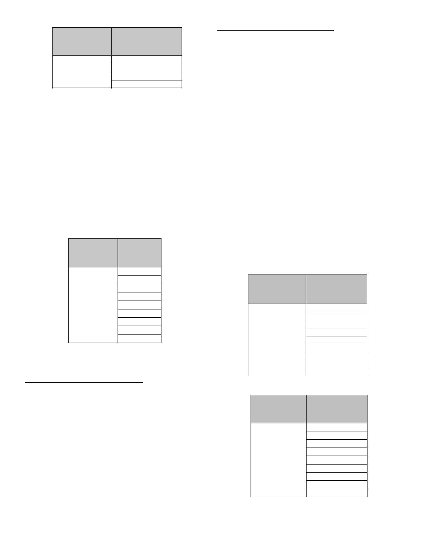
36
THERMOSTAT CALL AVAILABLE SPEEDS
W/W1
F01
F03
F04
F02 (DEFAULT)
Heating Speed Table for 1 Stage IFC
Continuous Fan Mode Speed Selection
To change the main blower speed in circulation mode,
follow the following steps:
1. Press the left or right switch until LED displays
“FSd”. Press the center switch and LED will display
the selected speed number as Fxx (xx: Blower
speed number from 1 to 9). F01 is the default speed
for circulation.
2. The control will rotate available speed number every
time left/right switches are pressed. All 9 speeds are
available for circulation.
3. When the center switch is pressed, the current
displayed speed will be selected, and control will
immediately apply that speed setting.
THERMOSTAT
CALL
AVAILABLE
SPEEDS
G
F01
F02
F03
(DEFAULT)
F04
F05
F06
F07
F08
F09
Circulation Speed Table
Cooling Mode Sequence of Operation
Low Stage Cooling Mode Sequence:
On a call for low stage cooling, the Y/Y1 or Y/Y1 and G
thermostat contacts close signaling the furnace control
board with 24 VAC on Y/Y1 or Y/Y1 and G terminals.
• The 7-Segment will display the cool mode:1 A C
• The compressor and condenser fan are energized.
• The circulator fan is energized at low cool speed after
a cool on delay. The electronic air cleaner will also be
energized.
• After the thermostat is satised, the compressor is
de-energized and the Cool Mode Fan O Delay period
begins.
• Following the Cool Mode Fan O Delay period, the
cool circulator and air cleaner relay are de-energized.
2nd Stage Cooling Mode Sequence:
On a call for 2nd stage cooling, the Y2 or Y2 and G
thermostat contacts close signaling the furnace control
board with 24 VAC on Y2 or Y2 and G terminals.
• The 7-Segment will display the cool mode: 2 A C
• The compressor and condenser fan are energized.
• The circulator fan is energized at cool speed after a
cool on delay. The electronic air cleaner will also be
energized.
• After the thermostat is satised, the compressor
is de-energized and the Cool Mode Fan O Delay
period begins.
• Following the Cool Mode Fan O Delay period, the
cool circulator and air cleaner relay are de-energized
Cooling Mode Speed Selection
To change the main blower speed in COOLING mode,
follow the following steps:
1. Press the left or right switch until LED displays “AC1
“(for single stage COOLING) or “AC2 “(for two-
stage COOLING). Press the center switch and LED
will display the selected speed number as Fxx (xx:
Blower speed number from 1 to 9).
2. The control will rotate available speed number every
time left/right switches are pressed. All 9 speeds are
available for both Single and Two Stage cooling.
3. When the center switch is pressed, the current
displayed speed will be selected, and control will
apply the newly selected speed in next cooling call.
THERMOSTATCALL AVAILABLESPEEDS
Y/Y1
F01
F02
F03
F04(DEFAULT)
F05
F06
F07
F08
F09
Single-Stage Cooling Speed Table for 2 Stage IFC
THERMOSTATCALL AVAILABLESPEEDS
Y2
F01
F02
F03
F04
F05(DEFAULT)
F06
F07
F08
F09
Two-Stage Cooling Speed Table for 2 Stage IFC
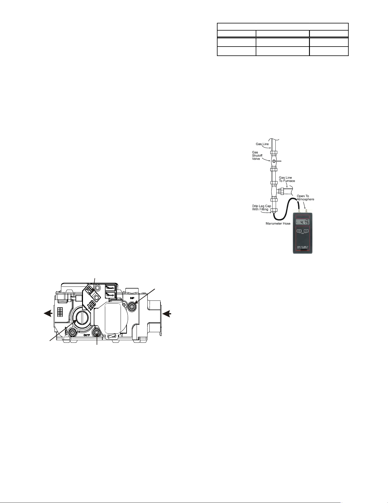
37
Furnace Shutdown
1. Set the thermostat to the lowest setting. The
integrated control will close the gas valve and
extinguish ame. Following a 15 second delay, the
induced draft blower will be de-energized. After
the blower o delay time expires, the blower de-
energizes.
2. Remove the burner compartment door and move
the furnace gas valve manual control to the OFF
position.
3. Close the manual gas shuto valve external to the
furnace.
4. Replace the burner compartment door.
GAS SUPPLY PRESSURE MEASUREMENT
Gas Pressure Test
The line pressure supplied to the gas valve must be within
the range specied below. The supply pressure can be
measured at the gas valve inlet pressure tap or at a hose
tting installed in the gas piping drip leg. The supply
pressure must be measured with the burners operating.
To measure the gas supply pressure, use the following
procedure.
1. Turn OFF gas to furnace at the manual gas shuto
valve external to the furnace.
2. Connect a calibrated manometer (or appropriate gas
pressure gauge) at either the gas valve inlet pressure
tap or the gas piping drip leg. See White-Rodgers
36J22 gas valve gure for location of inlet pressure
tap.
OUTLET
INLET
Gas Valve ON/OFF Selector Switch
Outlet Pressure
Inlet Pressure
Regulator
Cover Screw
White-Rodgers Model 36J22
Figure 48
NOTE: If measuring gas pressure at the drip leg, a
eld-supplied hose barb tting must be installed
prior to making the hose connection. If using the inlet
pressure tap on the White-Rodgers 36J22 gas valve,
then use the 36G/J Valve Pressure Check Kit, Part No.
0151K00000S.
3. Turn ON the gas supply and operate the furnace and
all other gas consuming appliances on the same gas
supply line.
4. Measure furnace gas supply pressure with burners
ring. Supply pressure must be within the range
specied in the Inlet Gas Supply Pressure table.
Gas Range No minal
Natural 3.2 - 3.8" w.c. 3.5" w.c.
Propane 9.7 - 10.3" w.c. 10.0" w.c.
Manifold Gas Pressure
If supply pressure diers from table, make the necessary
adjustments to pressure regulator, gas piping size, etc.,
and/or consult with local gas utility.
5. Turn OFF gas to furnace at the manual shuto valve and
disconnect manometer. Reinstall plug before turning on
gas to furnace.
6. Turn OFF any unnecessary gas appliances stated in step
3.
Measuring Inlet Gas Pressure (Alt. Method)
Figure 49
Gas Manifold Pressure Measurement and
Adjustment
Only small variations in gas pressure should be made by
adjusting the gas valve pressure regulator. The manifold
pressure must be measured with the burners operating.
To measure and adjust the manifold pressure, use the
following procedure.
1. Turn OFF gas to furnace at the manual gas shuto valve
external to the furnace.
2. Turn o all electrical power to the system.
3. Outlet pressure tap connections:
White-Rodgers 36J22 valve: Back outlet pressure
test screw (inlet/outlet pressure tap) out one turn
(counterclockwise, not more than one turn).
4. Attach a hose and manometer to the outlet pressure tap
(White-Rodgers valve).
5. Turn ON the gas supply.
6. Turn on power and close thermostat “R” and “W”
contacts to provide a call for heat.
7. Measure the gas manifold pressure with burners
ring. Adjust manifold pressure using the Manifold
Gas Pressure table shown on this page.
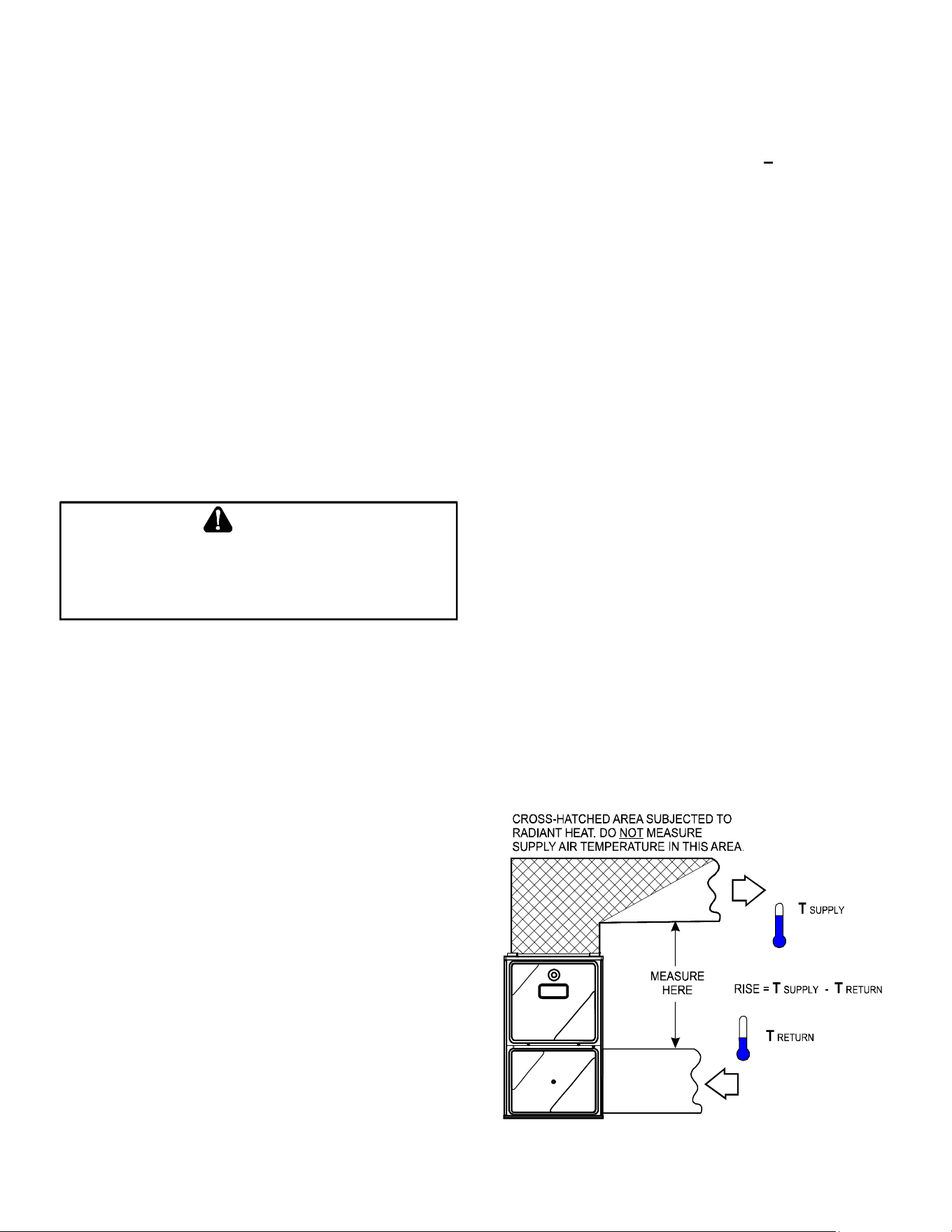
38
The typical value range for 1 cu. ft. of natural gas is around
1000 BTU. Check with your gas utility, if possible. In this
example, the furnace is consuming 78,000 BTUH.
NOTE: The nal manifold pressure cannot vary by
more than ± 0.3” w.c. for Natural and + 0.5” for LP from
the specied setting. Consult your local gas supplier
if additional input rate adjustment is required.
4. Turn ON gas to and relight all other appliances
turned o in step 1. Be certain that all appliances
are functioning properly and that all pilot burners are
operating.
Temperature Rise
Temperature rise must be within the range specied on the
unit rating plate. An incorrect temperature rise may result
in condensing in or overheating of the heat exchanger.
An airow and temperature rise table is provided in the
Specication Sheet applicable to your model. Determine
and adjust temperature rise as follows:
1. Operate furnace with burners ring for approximately
ten minutes. Ensure all registers are open and all
duct dampers are in their nal (fully or partially open)
position.
2. Place thermometers in the return and supply ducts
as close to the furnace as possible. Thermometers
must not be inuenced by radiant heat by being able
to “see” the heat exchanger.
3. Subtract the return air temperature from the supply
air temperature to determine the air temperature
rise. Allow adequate time for thermometer readings
to stabilize.
4. Adjust temperature rise by adjusting the circulator
blower speed. Increase blower speed to reduce
temperature rise. Decrease blower speed to
increase temperature rise. Refer to Startup
Procedure and Adjustment - Circulator Blower
Speeds for speed changing details.
SUPPLY
AIR
RETURN
AIR
Temperature Rise Measurement
Figure 50
8. Remove regulator cover screw from the outlet
pressure regulator adjust tower and turn screw
clockwise to increase pressure or counterclockwise
to decrease pressure. Replace regulator cover
screw.
9. Turn o all electrical power and gas supply to the
system.
10. Remove the manometer hose from the hose barb
tting or outlet pressure tap.
11. Replace outlet pressure tap: White-Rodgers 36J22
valve: Turn outlet pressure test screw in to seal pressure
port (clockwise, 7 in-lb minimum).
12. Turn on electrical power and gas supply to the
system.
13. Close thermostat contacts “R” and “W” to energize the
valve.
Using a leak detection solution or soap suds, check for
leaks at outlet or screw (White-Rodgers valve). Bubbles
forming indicate a leak. SHUT OFF GAS AND REPAIR
ALL LEAKS IMMEDIATELY!
NOTE: For gas to gas conversion, consult your dealer
for appropriate conversion.
CAUTION
T
O
PREVENT
UNRELIABLE
OPERATION
OR
EQUIPMENT
DAMAGE
,
THE
INLET
GAS
SUPPLY
PRESSURE
MUST
BE
AS
SPECIFIED
ON
THE
UNIT
RATING
PLATE
WITH
ALL
OTHER
HOUSEHOLD
GAS
FIRED
APPLIANCES
OPERATING
.
Gas Input Rate Measurement (Natural Gas Only)
The actual gas input rate to the furnace must never be
greater than that specied on the unit rating plate. To
measure natural gas input using the gas meter, use the
following procedure.
1. Turn OFF the gas supply to all other gas-burning
appliances except the furnace.
2. While the furnace is operating at high re rate, time
and record one complete revolution of the gas meter
dial, measuring the smallest quantity, usually the dial
that indicates 1/2 cu. ft. per revolution. You will use
this number to calculate the quantity of gas in cubic
ft. if the furnace would consume if it ran steadily for
one hour (3600 seconds).
3. If the 1/2 cu. ft. dial was used, multiply your number
x 2.
EXAMPLE: If it took 23 seconds to complete one
revolution of the 1/2 ft. dial (23 x 2 = 46).
This tells us that at this rate, it would take 46 seconds to
consume one cu. ft. of gas. 3600 / 46 = 78.
This tells us that in one hour, the furnace would consume
78 cu. ft. of gas.
39
OPERATIONAL CHECKS
The burner ames should be inspected with the burner
compartment door installed. Flames should be stable,
quiet, soft, and blue (dust may cause orange tips but
they must not be yellow). Flames should extend directly
outward from the burners without curling, oating, or lifting
o. Flames must not impinge on the sides of the heat
exchanger ring tubes.
SAFETY CIRCUIT DESCRIPTION
A number of safety circuits are employed to ensure safe
and proper furnace operation. These circuits serve to
control any potential safety hazards and serve as inputs
in the monitoring and diagnosis of abnormal function.
These circuits are continuously monitored during furnace
operation by the integrated control module.
WARNING
Do not bypass any safety circuit.
Integrated Control Module
The integrated control module is an electronic device
which, if a potential safety concern is detected, will
take the necessary precautions and provide diagnostic
information through an LED.
Primary Limit
The primary limit control is located on the partition panel
and monitors heat exchanger compartment temperatures.
It is a normally-closed (electrically), automatic reset,
temperature-activated sensor. The limit guards against
overheating as a result of insucient conditioned air
passing over the heat exchanger.
Auxiliary Limit
The auxiliary limit controls are located on or near the
circulator blower and monitors blower compartment
temperatures. They are a normally-closed (electrically),
manual-reset sensors. These limits guard against
overheating as a result of insucient conditioned air
passing over the heat exchanger.
Rollout Limit
The rollout limit controls are mounted on the burner/
manifold assembly and monitor the burner ame. They are
normally-closed (electrically), manual-reset sensors. These
limits guard against burner ames not being properly
drawn into the heat exchanger.
Pressure Switches
The pressure switches are normally-open (closed during
operation) negative air pressure-activated switches. They
monitor the airow (combustion air and ue products)
through the heat exchanger via pressure taps located on
the induced draft blower and the coil front cover. These
switches guard against insucient airow (combustion
air and ue products) through the heat exchanger and/or
blocked condensate drain conditions.
Flame Sensor
The ame sensor is a probe mounted to the burner/
manifold assembly which uses the principle of ame
rectication to determine the presence or absence of
ame.
MAINTENANCE
Annual Inspection
The furnace should be inspected by a qualied installer, or
service agency at least once per year. This check should
be performed at the beginning of the heating season.
This will ensure that all furnace components are in proper
working order and that the heating system functions
appropriately. Pay particular attention to the following
items. Repair or service as necessary.
• Flue pipe system. Check for blockage and/or leakage.
Check the outside termination and the connections at
and internal to the furnace.
• Heat exchanger. Check for corrosion and/or buildup
within the heat exchanger passageways.
• Burners. Check for proper ignition, burner ame, and
ame sense.
• Drainage system. Check for blockage and/or leakage.
Check hose connections at and internal to furnace.
• Wiring. Check electrical connections for tightness
and/or corrosion. Check wires for damage.
• Filters.
FILTERS
Filter Maintenance
Improper lter maintenance is the most common cause of
inadequate heating or cooling performance. Filters should
be cleaned (permanent) or replaced (disposable) every
two months or as required. When replacing a lter, it must
be replaced with a lter of the same type and size.
Filter Removal
Depending on the installation, diering lter arrangements
can be applied. Filters can be installed in either the central
return register or a side panel external lter rack (upow
only). A media air lter or electronic air cleaner can be
used as an alternate lter. Follow the lter sizes given in
the Recommended Minimum Filter size table to ensure
proper unit performance.
To remove lters from an external lter rack in an upright
upow installation, follow the directions provided with
external lter rack kit.
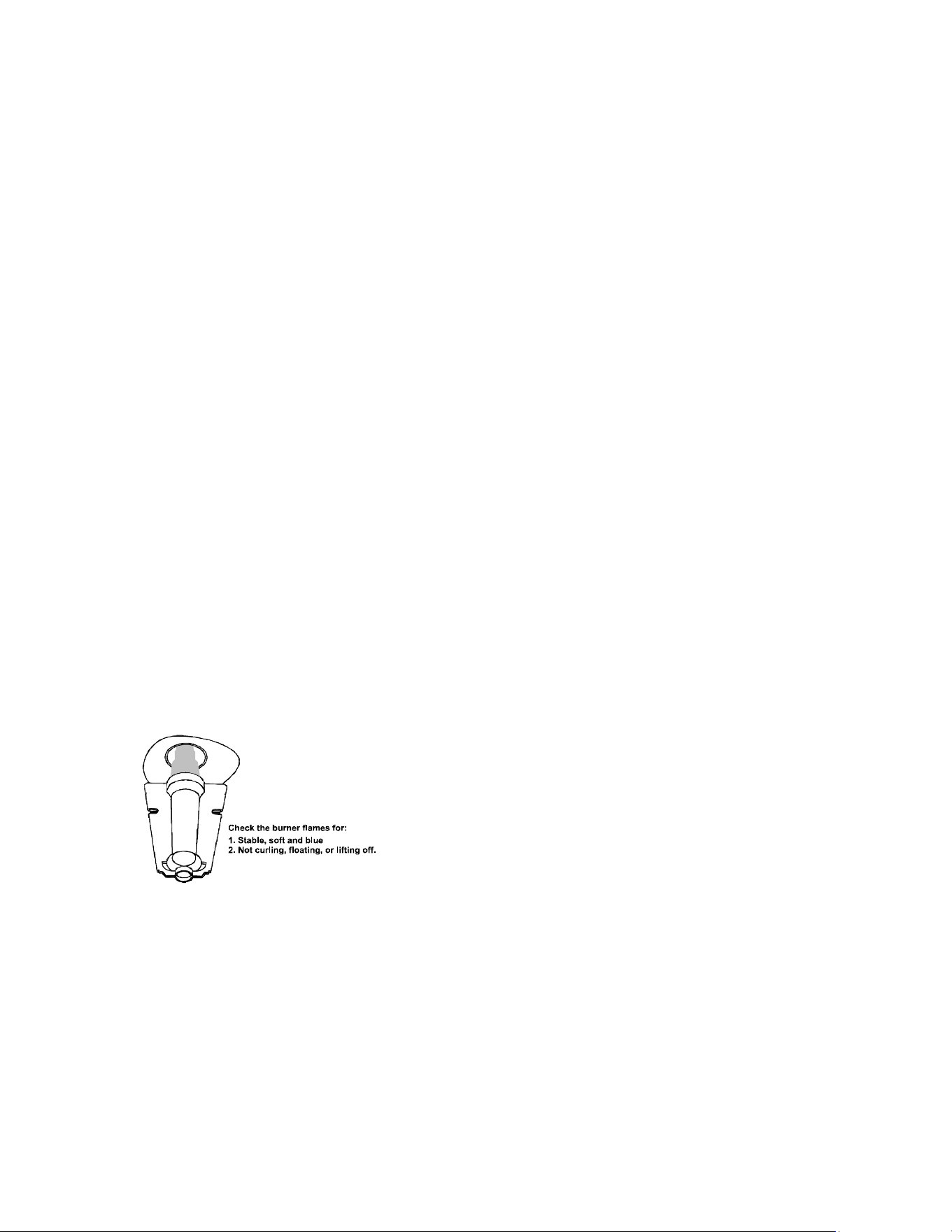
40
Flame Sensor (Qualified Servicer Only)
Under some conditions, the fuel or air supply can create a
nearly invisible coating on the ame sensor. This coating
acts as an insulator causing a drop in the ame sense
signal. If the ame sense signal drops too low the furnace
will not sense ame and will lock out. The ame sensor
should be carefully cleaned by a qualied servicer using
emery cloth or steel wool. Following cleaning, the ame
sense signal should be as indicated in the Specications
Sheet.
Flue Passages (Qualified Servicer Only)
The heat exchanger ue passageways should be
inspected at the beginning of each heating season.
BEFORE LEAVING AN INSTALLATION
• Cycle the furnace with the thermostat at least three
times. Verify cooling and fan only operation.
• Review the Owner’s Manual with the homeowner and
discuss proper furnace operation and maintenance.
• Leave literature packet near furnace.
REPAIR AND REPLACEMENT PARTS
• When ordering any of the listed functional parts, be
sure to provide the furnace model, manufacturing,
and serial numbers with the order.
• Although only functional parts are shown in the parts
list, all sheet metal parts, doors, etc. may be ordered
by description.
• Parts are available from your distributor.
Functional Parts List-
Gas Valve Blower Motor
Gas Manifold Blower Wheel
Natural Gas Orice Blower Mounting Bracket
Propane Gas Orice Blower Cuto
Igniter Blower Housing
Flame Sensor Pressure Switch
Rollout Limit Switch Door Switch
Primary Limit Switch Auxiliary Limit Switch
Coil Front Cover Integrated Control Module
Transformer Door Switch
Induced Draft Blower
Heat Exchanger with Recuperator Coil
Horizontal Unit Filter Removal
Filters in horizontal installations are located in the central
return register or the ductwork near the furnace.
To remove:
1. Turn OFF electrical power to furnace.
2. Remove lter(s) from the central return register or
ductwork.
3. Replace lter(s) by reversing the procedure for
removal.
4. Turn ON electrical power to furnace.
Media Air Filter or Electronic Air Cleaner
Removal
Follow the manufacturer’s directions for service.
Burners
Visually inspect the burner ames periodically during the
heating season. Turn on the furnace at the thermostat
and allow several minutes for ames to stabilize, since any
dislodged dust will alter the ames normal appearance.
Flames should be stable, quiet, soft, and blue (dust may
cause orange tips but they must not be yellow). They
should extend directly outward from the burners without
curling, oating, or lifting o. Flames must not impinge on
the sides of the heat exchanger ring tubes.
Induced Draft and Circulator Blowers
The bearings in the induced draft blower and circulator
blower motors are permanently lubricated by the
manufacturer. No further lubrication is required. Check
motor windings for accumulation of dust which may cause
overheating. Clean as necessary.
Burner Flame
Condensate Trap and Drain System (Qualified
Servicer Only)
Annually inspect the drain tubes, drain trap, and eld-
supplied drain line for proper condensate drainage. Check
drain system for hose connection tightness, blockage, and
leaks. Clean or repair as necessary.
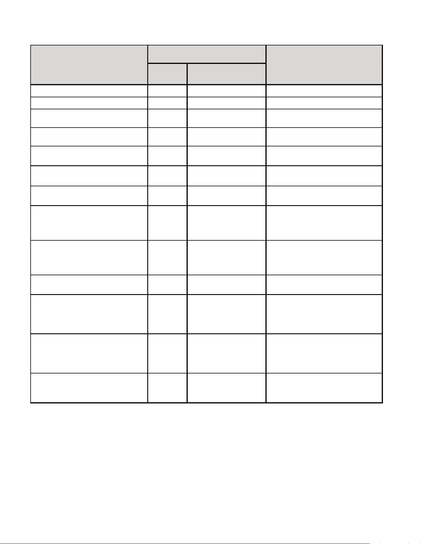
41
Main
Menu
Option Menu
Active Alaram menu
xx
( xx: code numbers )
Last 6 Faults
xx
( xx: code numbers )
Code Release Number
CR Number
Reset to Factory Default
yes, no
Blower Speed for Continous Fan Mode
xx
( xx: Blower Speed Number F01, F02.. )
Blower Speed for 1st Stage
Compressor Mode
xx
( xx: Blower Speed Number F01, F02.. )
Blower Speed for 2nd Stage
Compressor Mode
xx
( xx: Blower Speed Number F01, F02.. )
Cool On Delay
Delay, Seconds
Default set at 7 Secs, Adjustments can
be made in 7 Secs increments from 0 to
35 Secs
Cool Off Delay
Delay, Seconds
Default set at 65 Secs, Adjustments
can be made in 5 Secs increments from
0 to 120 Secs
Blower Speed for Gas Heat Mode
xx
( xx: Blower Speed Number F01, F02.. )
Gas Heat On Delay
Delay, Seconds
Default set at 30 Secs, Adjustments
can be made in 5 Secs increments from
5 to 30 Secs
Gas heat Off Delay
Delay, Seconds
Default set at 90 Secs, Adjustments
can be made in 30 Secs increments fro
m
30 to 180 Secs
Automatic Heat Staging - For Two
Stage Control
no, 10, 20, 30,
60, AUt
Refer to Section " CHANGING
HEATING MODE SETTING"
Menu Description
LED Display
Notes
1 Stage Status Codes
42
1 Stage Status Codes Status Menu
Idle
Continous Fan
Compressor Cooling, Low
Stage
Compressor Cooling, High
Stage
Gas heat - Single Stage
Control
OEM test Mode
Mode
Main
Menu
43
1 Stage Troubleshooting Codes
Symptom
LED
Status
Fault Description Corrective Actions
Normal operation Normal operation None
Locate and correct gas interruption
Replace or realign igniter
Check flame sense signal, clean sensor if coated or
oxidized
Check flue piping for blockage, proper length, elbows, and
termination
Verify proper induced draft blower perform ance
Pressure switch circuit is closed at start of
heating cycle
Pressure switch contacts sticking
Short in pressure switch circuit wiring
Pressure switch circuit is not closed
Pressure switch hose blocked pinched, or
connected improperly
Inspect flue piping for blockage, proper
length, elbows, and termination
Check induced draft blower performance, correct as
necessary
Incorrect pressure switch set point or
malfunctioning switch contacts
Check press ure switch operation, replace as needed
Loose or im properly connected wiring Tighten or correct wiring connection
Primary limit circuit is open
Check filters and ductwork for blockage Clean filters or
remove obstruction
Insufficient conditioned air over the heat
exchanger
Check circulator blower speed and performance
Blocked filters, restrictive ductwork, im proper
circulator blower speed, or failed circulator
blower motor
Correct speed or replace blower motor if necessary
Loose or im properly connected wiring in high
limit circuit
Tighten or correct wiring connection
Flame sensed with no call for heat Correct short at flame sensor or in flam e sensor wiring
Short to ground in flame sense circuit
Lingering burner flame Slow closing gas
valve
Open fuse Replace fuse
Short in low voltage wiring Locate and correct short in low voltage wiring
TROUBLESHOOTING CHART
Furnace fails to operate
Furnace lockout due to an excessive number
of ignition “retries” (3 total)
Failure to establish flame
Loss of flame after establishment
Furnace fails to operate Replace low stage pressure switch Repair short in wiring
Induced draft blower runs
continuously with no furnace
operation
Inspect pressure switch hose, repair/replace if necessary
Blocked flue and/or inlet air pi
pe, blocked
drain system or weak induced draft blower
Circulator blower runs
continuously
No furnace operation
Induced draft blower and
circulator blower runs
continuously
No furnace operation
Check for lingering or lazy flame Verify proper operation of
gas valve
No furnace operation
To View & Clear Fault Codes
• Press either the Left or Right switch until L 6 F is displayed.
• Press the center switch to view stored faults.
• Press and hold the center switch for 5 to 30 seconds.
• All stored faults will be erased, and the display will ash - - - three times and return to L 6 F.
44
1 Stage Troubleshooting Codes
Symptom
LED
Status
Fault Description Corrective Actions
Flame sense micro amp signal is minimal
Flame sensor is coated/oxidized
Flame sensor incorrectly positioned in burner
fame
Compare current gas pressure to rating plate and adjust
as needed
Problem with igniter circuit
Check and correct wiring from integrated control module to
igniter
Improperly connected or shorted igniter
Poor unit ground
Igniter relay fault on integrated control module
Check igniter output from control, replace if necessary
Polarity of 115 volt AC is reversed Correct polarity, check and correct wiring if necessary
Poor unit ground Verify proper ground, correct if necessary
Gas valve is not energized when it should be Check wiring in gas valve circuit
External Gas Valve Error Replace integrated control board
Gas valve is energized when it should not be Check wiring in gas valve circuit
Internal gas valve error Replace integrated
control board
Furnace fails to operate.
No 115 power to furnace or no 24 volt power
to integrated control module.
Restore high voltage power to furnace and integrated
control module.
Blown fuse or tripped circuit breaker
Correct condition which caused fuse to open, replace fuse
Integrated control module is non- functional
Replace non-functional integrated control module.
Furnace fails to operate
Grounding fault
Poor neutral connection
Verify neutral wire connection to furnace & continuity to
ground source
Furnace fails to operate Open roll out switch
Check for correct gas pressure Check for correct burner
alignment
Check for and correct burner restriction
Furnace fails to operate Ignitor Open
Check for Ignitor wiring.
Replace Damaged Ignitor
Furnace fails to operate
Inducer relay Error Replace integrated control board
Twinning feature not working TWIN Error
Check for wiring connections.
Replace integrated control board
Furnace fails to operate Internal Faults or IRQ Loss in Control Board Replace integrated control board
TROUBLESHOOTING CHART
Furnace fails to operate
Diagnose and replace shorted igniter as needed Verify and
correct unit ground wiring if needed
Normal furnace operation
Clean flame sensor if coated or oxidized Inspect for proper
flame sensor alignment
Lazy burner flame due to improper gas
pressure or combustion air
Furnace fails to operate
None
Integrated control module
LED display provides no
signal
Furnace fails to operate
Furnace fails to operate
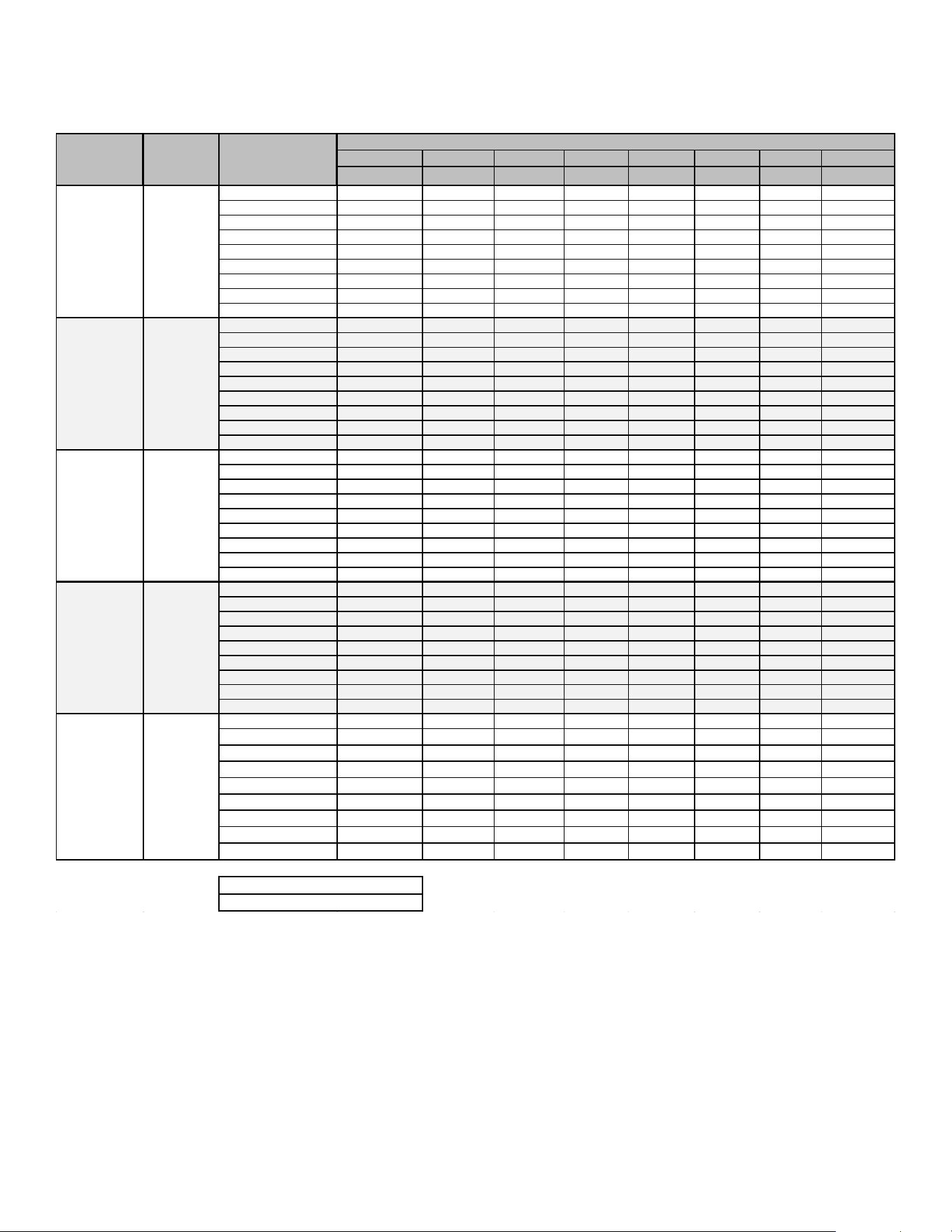
45
Airflow Tables - GC9S96
0.1 0.2
0.3 0.4
0.5
0.6
0.7 0.8
CFM CFM CFM CFM CFM
CFM CFM CFM
F01
632 574 510 448 388
332 277 234
F02
727 677 623 565 510 455
403 351
F03
878 839 797
751
701 653 607 561
F04^
948 910 870 828
785
739 693 652
F05
1106
1076
1044 1010
974 939
899
860
F06
1156
1125 1096 1063 1028 996 960 927
F07
1237 1205
1174
1145 1115
1081 1050
1016
F08
1334 1306 1275 1249 1220 1194
1163
1136
F09
1382 1354
1327
1302 1276
1246 1219 1190
F01
771 698
632
560
491
428
372 307
F02
1197 1150 1102 1057 1014 968 926
877
F03
1309
1264
1224
1180
1141 1098 1058 1018
F04^
1138 1091 1043 993 949 901 853 805
F05
944 884 824 774 716 660
605 554
F06
963 907 852
803 745
689 639 587
F07
1332
1289 1245
1200 1160
1120
1081 1036
F08
1366 1319 1277 1235 1192 1154 1117 1074
F09
1468 1436
1393 1359
1323
1285 1248 1210
F01
873
778 682 630
578 490 419 347
F02
1442 1386 1335 1280 1221 1157 1110
1054
F03
1643
1588 1534 1478
1415 1357 1299 1246
F04^
1600
1555 1505 1460 1412
1364 1309 1260
F05
1338 1269 1206
1133 1063 999 934 861
F06
1796 1744 1691 1638 1584 1532 1473 1422
F07
1874 1823 1775
1729 1675 1621 1567 1512
F08
1798 1754 1719
1672 1627 1585 1546 1497
F09
1991
1947
1900 1854 1808
1759 1707 1655
F01
1176 1107 1037 969 891 825 753 692
F02
1773 1721 1671 1621 1571 1521 1470 1421
F03
1709 1658 1607
1556
1503 1451
1399 1349
F04^
1651 1597
1542 1491 1437
1384
1332 1278
F05
1467
1409 1352 1307
1240 1182 1124
1063
F06
1834 1785
1738 1691 1643 1593 1545 1502
F07
1924 1881 1836 1796 1750 1701 1652 1606
F08
2028 1994 1937 1899 1863 1814 1769 1724
F09
2193 2145 2106
2076 2032 1998 1945 1903
F01
1187 1101
1013 931 847
764 677 604
F02 1973 1916 1864 1810 1756 1702 1650 1590
F03 1918 1859 1807 1748 1696 1643 1591 1531
F04^ 1835 1776 1720 1657 1602 1544 1483 1428
F05 1236 1152 1073 990 919 834 749 679
F06 1521 1459 1391 1327 1253 1187 1116 1053
F07 1673 1609 1549 1493 1430 1362 1305 1242
F08 2033 1981 1929 1878 1822 1771 1716 1669
F09 2257 2201 2151 2099 2057 2008 1959 1906
LOW STAGE COOLING AIFLOW
NOTE:
^ Default speed
MODEL
*C9S961205D*
Y/Y1
Y/Y1
*C9S960403B*
*C9S960603B*
*C9S960804C*
*C9S961005C*
TAP #
EXTERNAL STATIC PRESSURE, (INCHES WATER COLUMN)
Y/Y1
Y/Y1
Y/Y1
THERMOSTAT
CALL
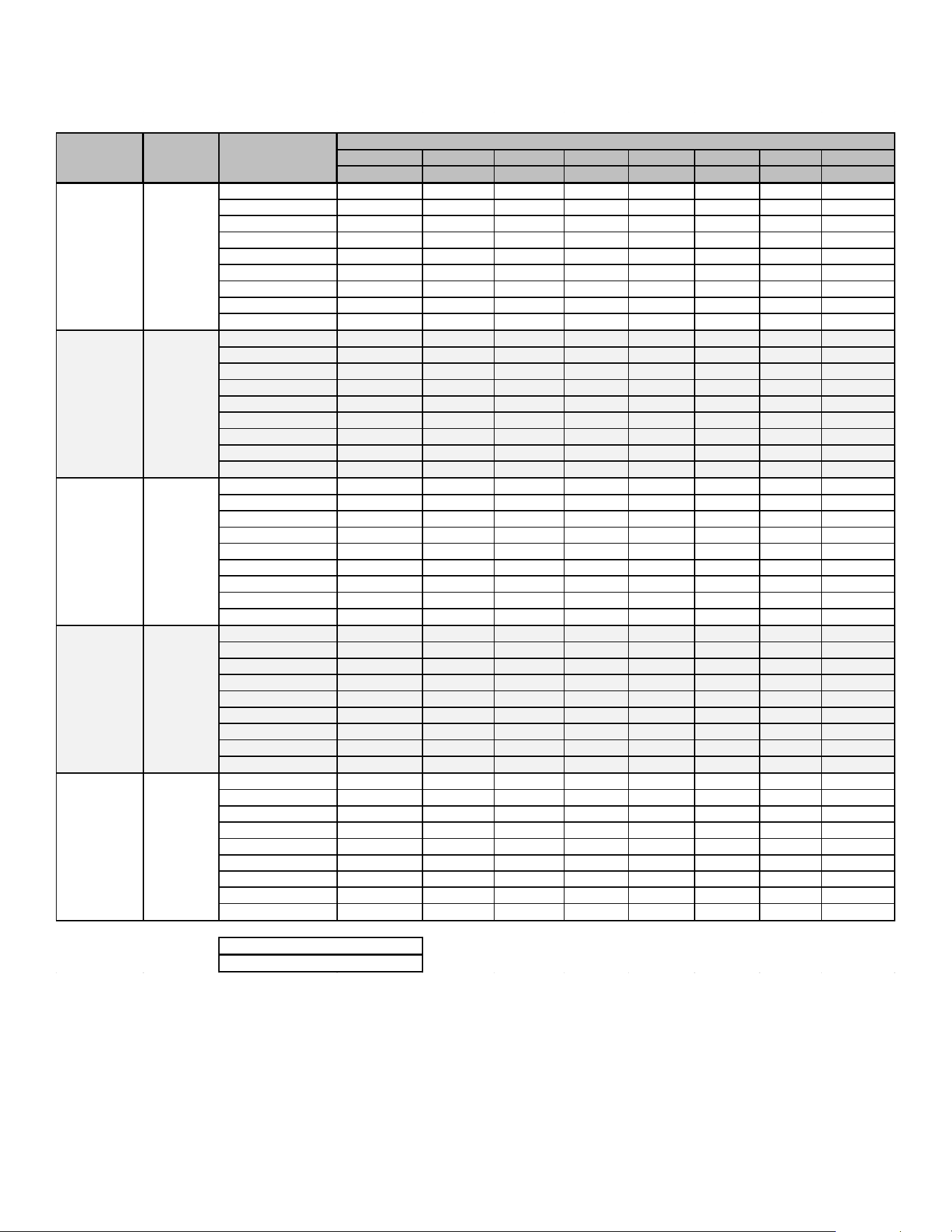
46
Airflow Tables - GC9S96
0.1 0.2 0.3 0.4
0.5 0.6 0.7 0.8
CFM CFM
CFM CFM CFM CFM
CFM
CFM
F01 632 574 510 448 388 332 277 234
F02 727 677 623 565 510 455 403 351
F03 878 839 797 751 701 653 607 561
F04 948 910 870 828 785 739 693 652
F05^ 1106 1076 1044 1010 974 939 899 860
F06 1156 1125 1096 1063 1028 996 960 927
F07 1237 1205 1174 1145 1115 1081 1050 1016
F08 1334 1306 1275 1249 1220 1194 1163 1136
F09 1382 1354 1327 1302 1276 1246 1219 1190
F01 771 698 632 560 491 428 372 307
F02 1197 1150 1102 1057 1014 968 926 877
F03 1309 1264 1224 1180 1141 1098 1058 1018
F04 1138 1091 1043 993 949 901 853 805
F05^ 944 884 824 774 716 660 605 554
F06 963 907 852 803 745 689 639 587
F07 1332 1289 1245 1200 1160 1120 1081 1036
F08 1366 1319 1277 1235 1192 1154 1117 1074
F09 1468 1436 1393 1359 1323 1285 1248 1210
F01 873 778 682 630 578 490 419 347
F02 1442 1386 1335 1280 1221 1157 1110 1054
F03 1643 1588 1534 1478 1415 1357 1299 1246
F04 1600 1555 1505 1460 1412 1364 1309 1260
F05^ 1338 1269 1206 1133 1063 999 934 861
F06 1796 1744 1691 1638 1584 1532 1473 1422
F07 1874 1823 1775 1729 1675 1621 1567 1512
F08 1798 1754 1719 1672 1627 1585 1546 1497
F09 1991 1947 1900 1854 1808 1759 1707 1655
F01 1176 1107 1037 969 891 825 753 692
F02 1773 1721 1671 1621 1571 1521 1470 1421
F03 1709 1658 1607 1556 1503 1451 1399 1349
F04 1651 1597 1542 1491 1437 1384 1332 1278
F05^ 1467 1409 1352 1307 1240 1182 1124 1063
F06 1834 1785 1738 1691 1643 1593 1545 1502
F07 1924 1881 1836 1796 1750 1701 1652 1606
F08 2028 1994 1937 1899 1863 1814 1769 1724
F09 2193 2145 2106 2076 2032 1998 1945 1903
F01 1187 1101 1013 931 847 764 677 604
F02 1973 1916 1864 1810 1756 1702 1650 1590
F03 1918 1859 1807 1748 1696 1643 1591 1531
F04 1835 1776 1720 1657 1602 1544 1483 1428
F05^ 1236 1152 1073 990 919 834 749 679
F06 1521 1459 1391 1327 1253 1187 1116 1053
F07 1673 1609 1549 1493 1430
1362 1305 1242
F08 2033 1981 1929 1878 1822 1771 1716 1669
F09 2257 2201 2151 2099 2057 2008 1959 1906
HIGH STAGE COOLING AIFLOW
TAP #
EXTERNAL STATIC PRESSURE, (INCHES WATER COLUMN)
^ Default speed
*C9S961005C*
Y2
*C9S961205D*
Y2
NOTE:
*C9S960804C*
Y2
MODEL
*C9S960603B*
Y2
THERMOSTAT
CALL
*C9S960403B*
Y2
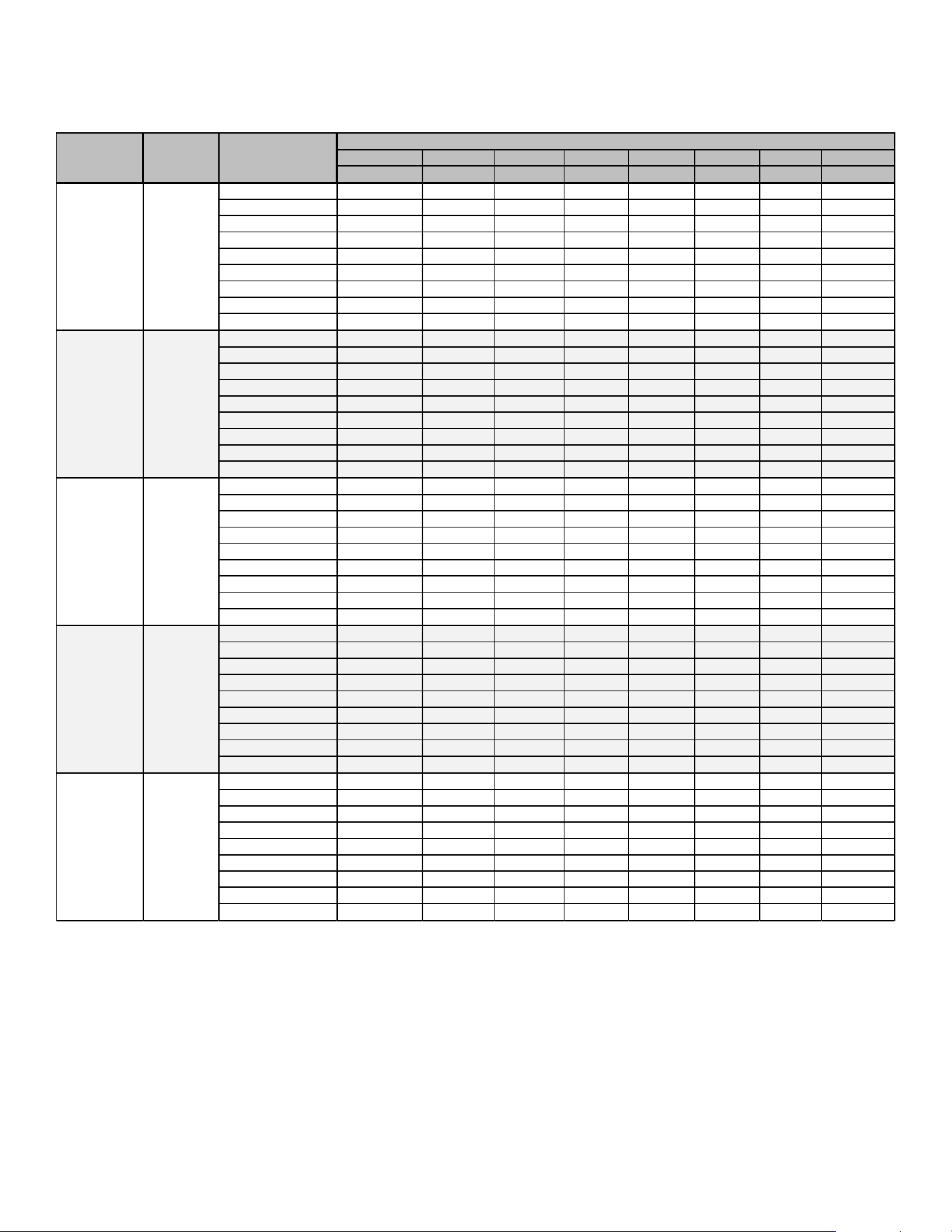
47
Airflow Tables - GC9S96
0.1
0.2 0.3
0.4
0.5 0.6
0.7 0.8
CFM
CFM CFM
CFM
CFM CFM CFM CFM
F01 632 574 510 448 388 332 277 234
F02 727 677 623 565 510 455 403 351
F03 878 839 797 751 701 653 607 561
F04 948 910 870 828 785 739 693 652
F05 1106 1076 1044 1010 974 939 899 860
F06 1156 1125 1096 1063 1028 996 960 927
F07 1237 1205 1174 1145 1115 1081 1050 1016
F08 1334 1306 1275 1249 1220 1194 1163 1136
F09 1382 1354 1327 1302 1276 1246 1219 1190
F01 771 698 632 560 491 428 372 307
F02 1197 1150 1102 1057 1014 968 926 877
F03 1309 1264 1224 1180 1141 1098 1058 1018
F04 1138 1091 1043 993 949 901 853 805
F05 944 884 824 774 716 660 605 554
F06 963 907 852 803 745 689 639 587
F07 1332 1289 1245 1200 1160 1120 1081 1036
F08 1366 1319 1277 1235 1192 1154 1117 1074
F09 1468 1436 1393 1359 1323 1285 1248 1210
F01 873 778 682 630 578 490 419 347
F02 1442 1386 1335 1280 1221 1157 1110 1054
F03 1643 1588 1534 1478 1415 1357 1299 1246
F04 1600 1555 1505 1460 1412 1364 1309 1260
F05 1338 1269 1206 1133 1063 999 934 861
F06 1796 1744 1691 1638 1584 1532 1473 1422
F07 1874 1823 1775 1729 1675 1621 1567 1512
F08 1798 1754 1719 1672 1627 1585 1546 1497
F09 1991 1947 1900 1854 1808 1759 1707 1655
F01 1176 1107 1037 969 891 825 753 692
F02 1773 1721 1671 1621 1571 1521 1470 1421
F03 1709 1658 1607 1556 1503 1451 1399 1349
F04 1651 1597 1542 1491 1437 1384 1332 1278
F05 1467 1409 1352 1307 1240 1182 1124 1063
F06 1834 1785 1738 1691 1643 1593 1545 1502
F07 1924 1881 1836 1796 1750 1701 1652 1606
F08 2028 1994 1937 1899 1863 1814 1769 1724
F09 2193 2145 2106 2076 2032 1998 1945 1903
F01 1187 1101 1013 931 847 764 677 604
F02 1973 1916 1864 1810 1756 1702 1650 1590
F03 1918 1859 1807 1748 1696 1643 1591 1531
F04 1835 1776 1720 1657 1602 1544 1483 1428
F05 1236 1152 1073 990 919 834 749 679
F06 1521 1459 1391 1327 1253 1187 1116 1053
F07 1673 1609 1549 1493 1430
1362 1305 1242
F08 2033 1981 1929 1878 1822 1771 1716 1669
F09 2257 2201 2151 2099 2057 2008 1959 1906
CIRCULATION AIFLOW
*C9S960403B*
G
*C9S961005C*
G
*C9S961205D*
G
*C9S960603B*
G
*C9S960804C*
G
MODEL
THERMOSTAT
CALL
TAP #
EXTERNAL STATIC PRESSURE, (INCHES WATER COLUMN)
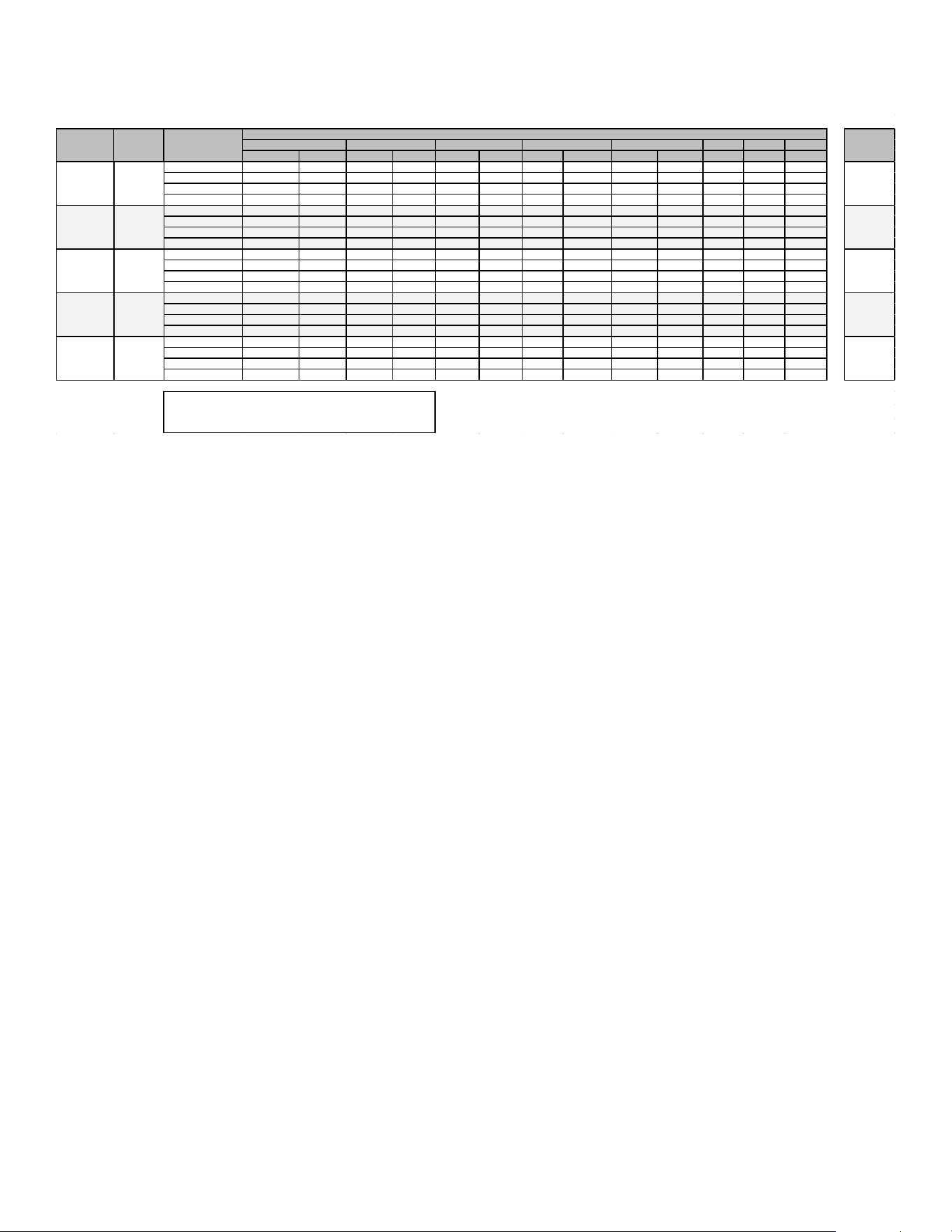
48
Airflow Tables - GC9S96
0.6 0.7 0.8
CFM RISE CFM RISE CFM RISE CFM RISE CFM RISE CFM CFM CFM
F01^^ 632 N/A 574 N/A 510 N/A 448 N/A 388 N/A 332 277 234
F02^ 727 48 677
51 623 54 565 60 510 65 455 403 351
F03 878
41 839 42 797 45 751 47 701 51 653 607 561
F04 948 38 910 39 870 41 828 43 785 45 739 693 652
F01^^ 771 N/A 698 N/A 632 N/A 560 N/A 491 N/A 428 372 307
F02^ 1197 45
1150 46 1102 48 1057 50 1014 53 968 926 877
F03 1309 41 1264 42 1224 44 1180 45 1141 47 1098 1058 1018
F04 1138 47 1091 49 1043 51 993 54 949 56 901 853 805
F01^^ 873 N/A 778 N/A 682 N/A 630 N/A 578 N/A 490 419 347
F02^ 1442 49 1386 51 1335 53 1280 56 1221 58 1157 1110 1054
F03 1643 43 1588 45
1534 46 1478 48 1415 50 1357 1299 1246
F04 1600 44 1555 46 1505
47 1460 49 1412 50 1364 1309 1260
F01^^ 1176 N/A 1107 N/A 1037 N/A 969 N/A 891 N/A 825 753 692
F02^ 1773 50 1721 52 1671 53 1621 55 1571 57 1521 1470 1421
F03^^ 1709 52 1658 54 1607 55 1556 57 1503 59 1451 1399 1349
F04 1651 54 1597 56 1542
58 1491 60 1437 62 1384 1332 1278
F01^^ 1187 N/A 1101 N/A 1013 N/A 931 N/A 847 N/A 764 677 604
F02^ 1973 54 1916 56 1864 57 1810 59 1756 61 1702 1650 1590
F03 1918 56 1859 57 1807 59 1748 61 1696 63 1643 1591 1531
F04 1835 58 1776 60 1720 62 1657 64 1602 67 1544 1483 1428
HEATING AIFLOW
*C9S960403B*
*C9S960603B*
45-75
W/W1
40-70
W/W1
40-70
*C9S960804C*
*C9S961005C*
*C9S961205D*
MODEL
THERMOSTAT
CALL
TAP #
EXTERNAL STATIC PRESSURE, (INCHES WATER COLUMN)
TEMP RANGE
0.1
0.2
0.3
0.4
0.5
^^NOT RECOMMENDED FOR HEATING
W/W1
W/W1
35-65
W/W1
35-65
NOTE:
^DEFAULT & RECOMMENDED
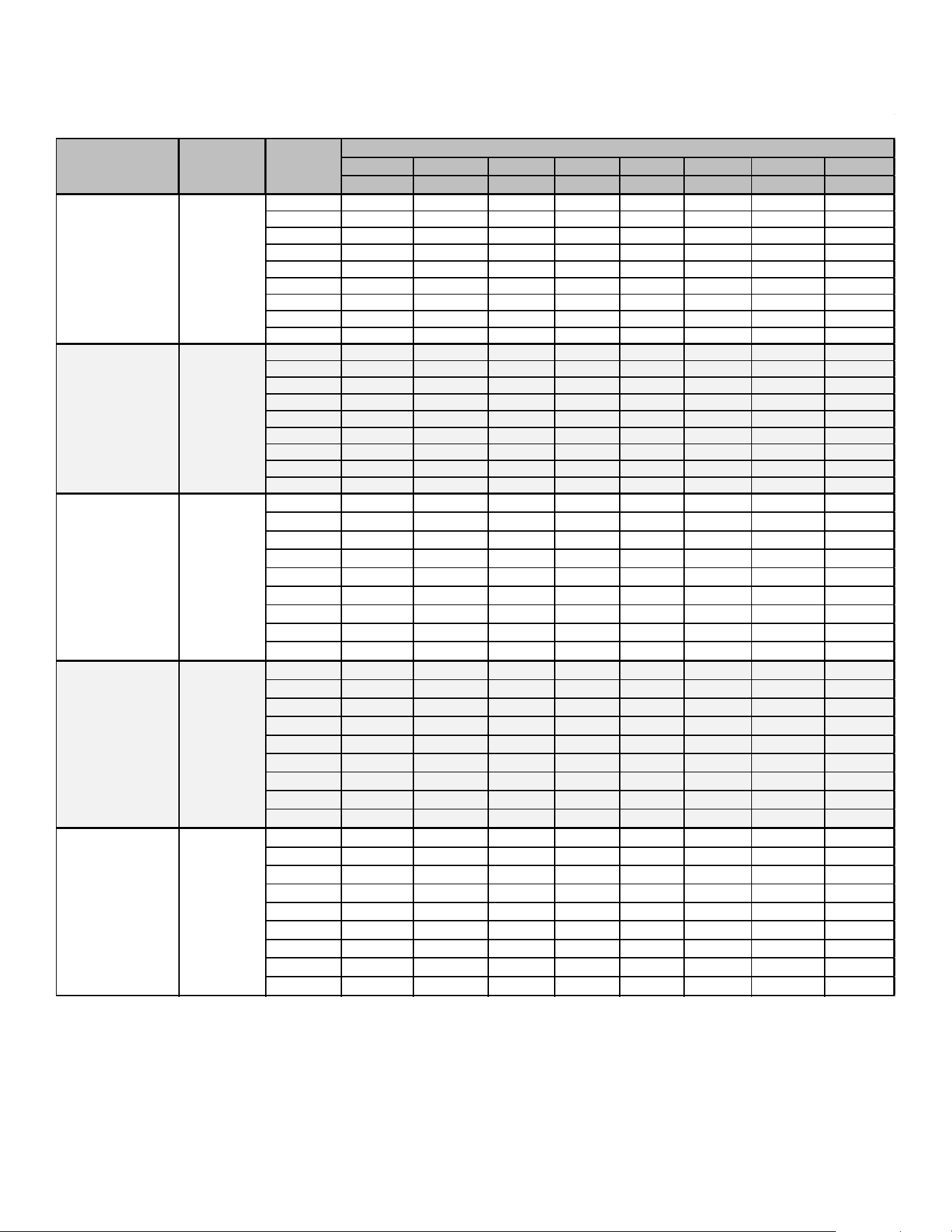
49
Airflow Tables - GM9S92
0.1 0.2 0.3 0.4 0.5 0.6 0.7
0.8
CFM CFM CFM CFM CFM CFM CFM CFM
F01
610 559 513 467 419 368 316
285
F02
925 887 852 818 787 754 720
685
F03
846 808 772 737 703 667 630 594
F04^
781 739 701 663 625 586 547 508
F05
1038
1003 970
940 909
879
849
820
F06
1106 1072
1041
1011 981
953 926 898
F07
1215
1180 1151
1121 1095
1066
1043
1017
F08
1238 1210
1180
1153 1126
1099 1073
1047
F09
1319 1299 1273 1246 1220 1194
1169 1146
F01
723 663 604 539 476 404 347
291
F02
1052 1010
962
920 875
829 785
740
F03
1125 1084 1042 1003 964 918 875 834
F04^
1206 1166 1129 1091 1054 1012 977
947
F05
901 854
809 758 703 653 604
552
F06
948 900 855
810 762
708 662
608
F07
1273 1237 1206
1169
1128 1094
1057
1020
F08
1365 1321 1292 1251 1219 1184 1152 1120
F09
1426
1387 1360 1326 1292 1257 1226 1193
F01 718 662 611 551 486 419 358
300
F02 1373 1341 1307
1279
1253 1226
1197 1172
F03 1309 1265 1232 1192 1162 1129 1093
1057
F04^ 1233 1194 1165 1131 1097 1070 1039 1008
F05
874
828 791 750 703
655 602 547
F06
950 908 865 826
786 739 689 638
F07 1097
1056
1019 988 952 921 880 842
F08
1166 1127 1092 1060
1027 994 960
926
F09 1407
1373 1338 1308 1282
1253 1229 1203
F01 804
740
670 586 501 407 347 N/A
F02 1422
1375
1332 1288
1245 1200
1154 1108
F03 1502 1455 1410
1365 1322
1278 1237 1195
F04^ 1567
1519 1476
1441 1402
1360 1319 1278
F05
1347 1299 1253 1205 1157 1111 1063 1013
F06 1692 1648 1609 1567 1529
1490 1451 1413
F07 1772 1728 1689 1652 1614 1574
1534 1498
F08 1793 1753 1720 1679 1643 1604 1562 1524
F09 1875 1833
1797 1759 1727
1686 1652 1616
F01 869 782 684
575 482 395 331 122
F02 1823 1776 1720 1679
1642
1597 1553 1504
F03 1778 1729 1690 1648 1605 1558 1497 1449
F04^ 1722 1660 1609 1553 1507 1455 1402 1350
F05 1498 1442
1388 1332 1278 1215 1154
1090
F06 1634 1583 1536 1489
1440 1387 1330 1275
F07
1925 1879 1836 1795 1752 1711 1664
1621
F08 1993 1941 1899 1852 1813 1778
1741 1693
F09 2216 2172 2131 2087
2046 2011 1973 1935
*M9S920603B*
Y/Y1
*M9S920803B*
Y/Y1
*M9S920804C*
Y/Y1
MODEL
THERMOSTAT
CALL
TAP #
EXTERNAL STATIC PRESSURE, (INCHES WATER COLUMN)
*M9S920403A*
Y/Y1
*M9S920805C*
Y/Y1
LOW STAGE COOLING AIFLOW
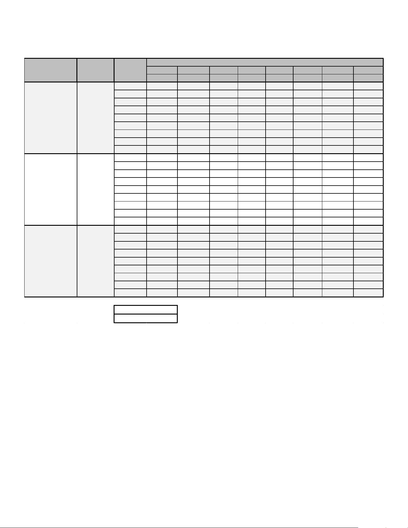
50
Airflow Tables - GM9S92
0.1 0.2 0.3 0.4 0.5 0.6 0.7 0.8
CFM CFM CFM CFM CFM CFM CFM CFM
F01 809 740 669 603 536 449 377 319
F02 1754 1707 1673 1640 1604 1568 1538 1509
F03 1648 1620 1586 1552 1515 1480 1449 1412
F04^ 1558 1517 1479 1441 1403 1366 1330 1295
F05 1303 1255 1210 1167 1125 1081 1041 999
F06 1406 1362 1321 1281 1240 1197 1157 1118
F07 1445 1403 1363 1324 1287 1247 1208 1167
F08 1778 1743 1700 1669 1634 1600 1568 1542
F09 1824 1785 1747 1714 1680 1647 1617 1585
F01 906 813 717 613 519 439 368 N/A
F02 1871 1818 1769 1720 1667 1614 1565 1511
F03 1831 1782 1729 1679 1624 1571 1520 1465
F04^ 1653 1596 1538 1480 1422 1362 1306 1247
F05 1496 1437 1376 1315 1250 1189 1126 1056
F06 1640 1587 1527 1471 1414 1357 1294 1235
F07 1955 1937 1909 1860 1813 1765 1712 1662
F08 2086 2039 1991 1944 1896 1855 1810 1763
F09 2222 2178 2133 2088 2043 1998 1954 1910
F01 1056 962 866 772 666 574 501 429
F02 2096 2050 2005 1948 1899 1848 1800 1755
F03 2023 1973 1927 1877 1829 1781 1731 1680
F04^ 1946 1900 1848 1795 1741 1689 1637 1584
F05 1231 1151 1078 992 913 812 725 651
F06 1503 1440 1382 1318 1251 1179 1108 1039
F07 1704 1646 1586 1532 1473 1412 1346 1284
F08 1831 1775 1720 1668 1610 1560 1511 1457
F09 2222 2173 2125 2078 2029 1980 1933 1884
*M9S921205D*
Y/Y1
NOTE:
^ Default speed
*M9S921004C*
Y/Y1
*M9S921005C*
Y/Y1
MODEL
THERMOSTAT
CALL
TAP #
EXTERNAL STATIC PRESSURE, (INCHES WATER COLUMN)
LOW STAGE COOLING AIFLOW
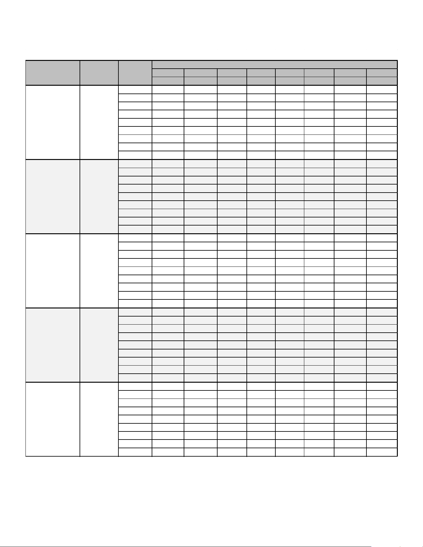
51
Airflow Tables - GM9S92
0.1 0.2 0.3 0.4 0.5 0.6 0.7 0.8
CFM CFM CFM CFM CFM CFM CFM CFM
F01 610 559 513 467 419 368 316 285
F02 925 887 852 818 787 754 720 685
F03 846 808 772 737 703 667 630 594
F04 781 739 701 663 625 586 547 508
F05^ 1038 1003 970 940 909 879 849 820
F06 1106 1072 1041 1011 981 953 926 898
F07 1215 1180 1151 1121 1095 1066 1043 1017
F08 1238 1210 1180 1153 1126 1099 1073 1047
F09 1319 1299 1273 1246 1220 1194 1169 1146
F01 723 663 604 539 476 404 347 291
F02 1052 1010 962 920 875 829 785 740
F03 1125 1084 1042 1003 964 918 875 834
F04 1206 1166 1129 1091 1054 1012 977 947
F05^ 901 854 809 758 703 653 604 552
F06 948 900 855 810 762 708 662 608
F07 1273 1237 1206 1169 1128 1094 1057 1020
F08 1365 1321 1292 1251 1219 1184 1152 1120
F09 1426 1387 1360 1326 1292 1257 1226 1193
F01 718 662 611 551 486 419 358 300
F02 1373 1341 1307 1279 1253 1226 1197 1172
F03 1309 1265 1232 1192 1162 1129 1093 1057
F04 1233 1194 1165 1131 1097 1070 1039 1008
F05^ 874 828 791 750 703 655 602 547
F06 950 908 865 826 786 739 689 638
F07 1097 1056 1019 988 952 921 880 842
F08 1166 1127 1092 1060 1027 994 960 926
F09 1407 1373 1338 1308 1282 1253 1229 1203
F01 804 740 670 586 501 407 347 N/A
F02 1422 1375 1332 1288 1245 1200 1154 1108
F03 1502 1455 1410 1365 1322 1278 1237 1195
F04 1567 1519 1476 1441 1402 1360 1319 1278
F05^ 1347 1299 1253 1205 1157 1111 1063 1013
F06 1692 1648 1609 1567 1529 1490 1451 1413
F07 1772 1728 1689 1652 1614 1574 1534 1498
F08 1793 1753 1720 1679 1643 1604 1562 1524
F09 1875 1833 1797 1759 1727 1686 1652 1616
F01 869 782 684 575 482 395 331 122
F02 1823 1776 1720 1679 1642 1597 1553 1504
F03 1778 1729 1690 1648 1605 1558 1497 1449
F04 1722 1660 1609 1553 1507 1455 1402 1350
F05^ 1498 1442 1388 1332 1278 1215 1154 1090
F06 1634 1583 1536 1489 1440 1387 1330 1275
F07 1925 1879 1836 1795 1752
1711 1664 1621
F08 1993 1941 1899 1852 1813 1778 1741 1693
F09 2216 2172 2131 2087 2046 2011 1973 1935
*M9S920804C*
Y2
*M9S920805C*
Y2
*M9S920403A*
Y2
*M9S920603B*
Y2
*M9S920803B*
Y2
MODEL
THERMOSTAT
CALL
TAP #
EXTERNAL STATIC PRESSURE, (INCHES WATER COLUMN)
HIGH STAGE COOLING AIFLOW
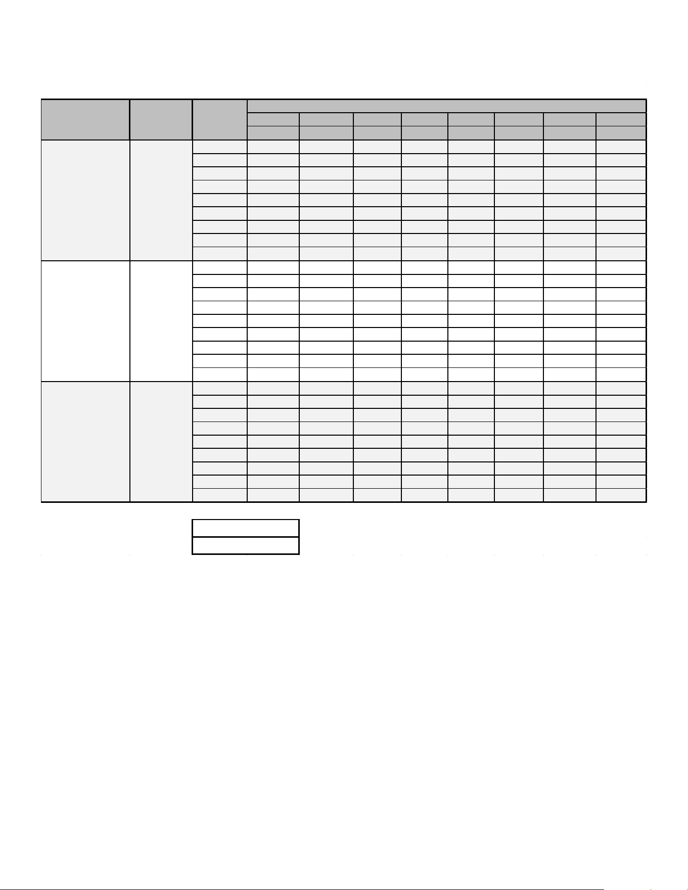
52
Airflow Tables - GM9S92
0.1 0.2 0.3 0.4 0.5 0.6 0.7 0.8
CFM CFM CFM CFM CFM CFM CFM CFM
F01 809 740 669 603 536 449 377 319
F02 1754 1707 1673 1640 1604 1568 1538 1509
F03 1648 1620 1586 1552 1515 1480 1449 1412
F04 1558 1517 1479 1441 1403 1366 1330 1295
F05^ 1303 1255 1210 1167 1125 1081 1041 999
F06 1406 1362 1321 1281 1240 1197 1157 1118
F07 1445 1403 1363 1324 1287 1247 1208 1167
F08 1778 1743 1700 1669 1634 1600 1568 1542
F09 1824 1785 1747 1714 1680 1647 1617 1585
F01 906 813 717 613 519 439 368 N/A
F02 1871 1818 1769 1720 1667 1614 1565 1511
F03 1831 1782 1729 1679 1624 1571 1520 1465
F04 1653 1596 1538 1480 1422 1362 1306 1247
F05^ 1496 1437 1376 1315 1250 1189 1126 1056
F06 1640 1587 1527 1471 1414 1357 1294 1235
F07 1955 1937 1909 1860 1813 1765 1712 1662
F08 2086 2039 1991 1944 1896 1855 1810 1763
F09 2222 2178 2133 2088 2043 1998 1954 1910
F01 1056 962 866 772 666 574 501 429
F02 2096 2050 2005 1948 1899 1848 1800 1755
F03 2023 1973 1927 1877 1829 1781 1731 1680
F04 1946 1900 1848 1795 1741 1689 1637 1584
F05^ 1231 1151 1078 992 913 812 725 651
F06 1503 1440 1382 1318 1251 1179 1108 1039
F07 1704 1646 1586 1532 1473 1412 1346 1284
F08 1831 1775 1720 1668 1610 1560 1511 1457
F09 2222 2173 2125 2078 2029 1980 1933 1884
*M9S921005C*
Y2
*M9S921205D*
Y2
NOTE:
^ Default speed
*M9S921004C*
Y2
MODEL
THERMOSTAT
CALL
TAP #
EXTERNAL STATIC PRESSURE, (INCHES WATER COLUMN)
HIGH STAGE COOLING AIFLOW
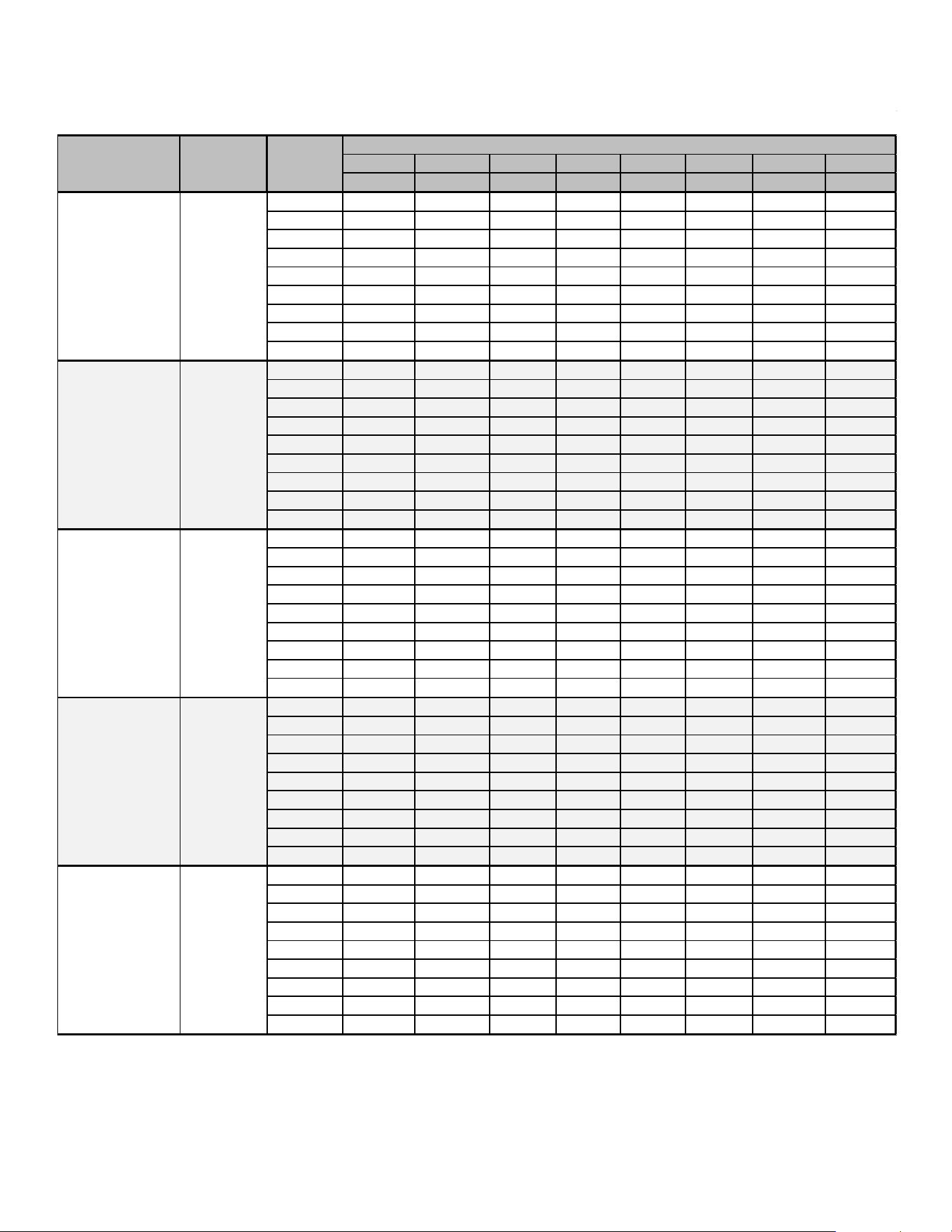
53
Airflow Tables - GM9S92
0.1
0.2 0.3
0.4
0.5 0.6
0.7 0.8
CFM CFM
CFM CFM
CFM
CFM CFM CFM
F01 610
559 513 467 419 368 316 285
F02 925 887 852 818 787 754 720 685
F03 846
808 772 737 703 667 630 594
F04 781 739 701 663 625 586 547 508
F05 1038 1003 970 940 909 879 849 820
F06
1106 1072 1041 1011 981 953 926
898
F07
1215 1180 1151 1121 1095 1066 1043 1017
F08
1238 1210 1180 1153 1126 1099 1073
1047
F09
1319 1299 1273 1246 1220 1194 1169 1146
F01 723 663 604 539 476 404 347
291
F02
1052 1010 962 920 875 829 785
740
F03 1125 1084 1042 1003 964 918 875 834
F04
1206 1166 1129 1091 1054 1012 977
947
F05 901 854 809 758 703 653 604 552
F06 948 900 855 810 762 708 662 608
F07 1273 1237
1206 1169 1128 1094
1057 1020
F08 1365 1321 1292 1251 1219 1184 1152 1120
F09 1426 1387 1360 1326 1292 1257 1226 1193
F01 718
662 611 551 486 419
358 300
F02 1373
1341 1307 1279 1253 1226
1197 1172
F03 1309
1265 1232 1192 1162 1129 1093 1057
F04
1233 1194
1165 1131 1097 1070 1039
1008
F05 874
828 791 750 703 655 602 547
F06 950 908 865 826 786 739 689 638
F07 1097
1056 1019
988 952 921
880 842
F08 1166
1127 1092
1060 1027 994
960 926
F09 1407 1373 1338 1308 1282
1253 1229
1203
F01 804 740 670 586 501 407 347 N/A
F02
1422 1375 1332 1288 1245 1200
1154
1108
F03
1502 1455 1410 1365 1322 1278 1237 1195
F04 1567 1519
1476 1441 1402 1360 1319
1278
F05 1347 1299 1253
1205 1157
1111
1063 1013
F06 1692 1648 1609 1567 1529 1490 1451 1413
F07 1772
1728 1689 1652 1614 1574 1534
1498
F08 1793 1753 1720 1679
1643 1604 1562 1524
F09 1875 1833 1797 1759 1727 1686
1652 1616
F01 869
782 684 575 482
395 331 122
F02
1823 1776 1720 1679 1642 1597 1553 1504
F03 1778 1729 1690
1648 1605 1558 1497 1449
F04 1722 1660 1609
1553 1507 1455 1402 1350
F05 1498 1442 1388 1332 1278
1215
1154 1090
F06 1634 1583 1536 1489 1440 1387 1330 1275
F07 1925 1879
1836 1795 1752 1711
1664 1621
F08 1993 1941 1899 1852 1813 1778 1741 1693
F09 2216
2172 2131 2087 2046 2011 1973
1935
CIRCULATION AIRFLOW
*M9S920805C*
G
*M9S920603B*
G
*M9S920803B*
G
*M9S920804C*
G
MODEL
THERMOSTAT
CALL
TAP #
EXTERNAL STATIC PRESSURE, (INCHES WATER COLUMN)
*M9S920403A*
G
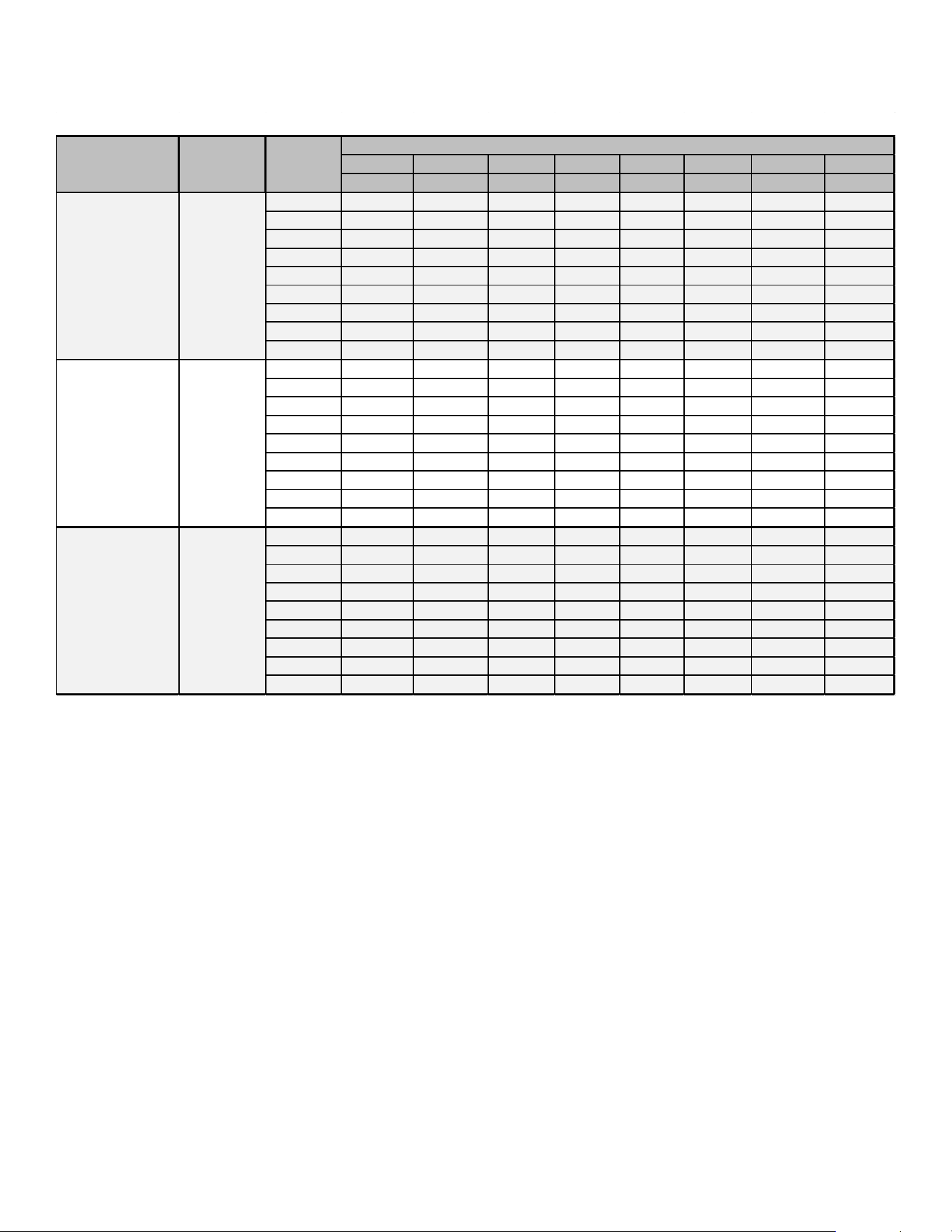
54
Airflow Tables - GM9S92
0.1
0.2 0.3 0.4 0.5 0.6
0.7 0.8
CFM CFM CFM CFM CFM CFM
CFM CFM
F01
809 740 669 603 536 449 377 319
F02 1754 1707
1673 1640 1604 1568 1538 1509
F03 1648
1620 1586 1552 1515 1480 1449 1412
F04
1558 1517 1479 1441 1403 1366 1330 1295
F05
1303 1255 1210 1167 1125 1081 1041 999
F06 1406 1362 1321 1281
1240
1197 1157 1118
F07 1445 1403 1363 1324 1287 1247 1208 1167
F08 1778 1743 1700 1669 1634 1600 1568 1542
F09 1824 1785 1747 1714 1680 1647 1617 1585
F01 906 813 717 613 519 439
368
N/A
F02
1871
1818 1769 1720
1667 1614
1565 1511
F03 1831 1782 1729 1679 1624 1571 1520 1465
F04 1653 1596 1538 1480 1422 1362 1306 1247
F05 1496
1437 1376 1315 1250
1189 1126
1056
F06
1640 1587 1527
1471 1414 1357 1294 1235
F07 1955
1937 1909 1860 1813 1765 1712 1662
F08 2086 2039 1991 1944 1896 1855
1810 1763
F09 2222 2178 2133 2088 2043 1998 1954 1910
F01 1056 962 866 772 666 574 501 429
F02 2096 2050 2005 1948 1899 1848 1800 1755
F03 2023 1973 1927 1877 1829 1781 1731 1680
F04 1946 1900 1848 1795 1741 1689 1637 1584
F05 1231 1151 1078 992 913 812 725 651
F06 1503 1440 1382 1318 1251 1179 1108 1039
F07 1704 1646 1586 1532 1473 1412 1346 1284
F08 1831 1775 1720 1668 1610 1560 1511 1457
F09 2222 2173 2125 2078 2029 1980 1933 1884
CIRCULATION AIRFLOW
*M9S921205D*
G
*M9S921004C*
G
*M9S921005C*
G
MODEL
THERMOSTAT
CALL
TAP #
EXTERNAL STATIC PRESSURE, (INCHES WATER COLUMN)
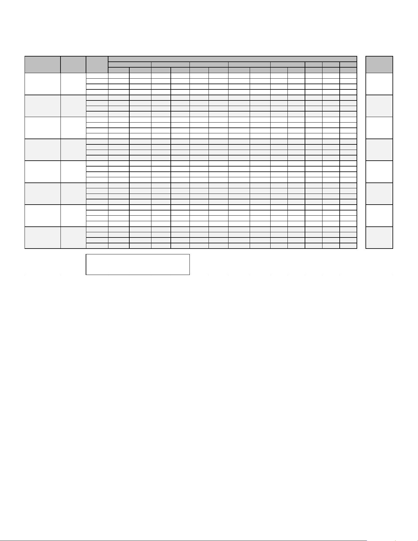
55
Airflow Tables - GM9S92
0.6 0.7 0.8
CFM
RISE
CFM
RISE CFM RISE CFM RISE CFM RISE
CFM CFM
CFM
F01^^ 610 56 559 N/A 513 N/A 467 N/A 419 N/A 368 316 285
F02^ 925 37 887 38 852 40 818 42 787 43 754 720 685
F03 846 40 808 42 772 44 737 46 703 49 667 630 594
F04 781 44 739 46 701 49 663 51 625 55 586 547 508
F01^^ 723 N/A 663 N/A 604 N/A 539 N/A 476 N/A 404 347 291
F02^ 1052 49 1010 51 962 53 920 56 875 58 829 785 740
F03 1125 45 1084 47 1042 49 1003 51 964 53 918 875 834
F04 1206 42 1166 44 1129 45 1091 47 1054 48 1012 977 947
F01^^ 718 N/A 662 N/A 611 N/A 551 N/A 486 N/A 419 358 300
F02^ 1373 50 1341 51 1307 52 1279 53 1253 54 1226 1197 1172
F03 1309 52 1265 54 1232 55 1192 57 1162 59 1129 1093 1057
F04 1233 55 1194 57 1165 59 1131 60 1097 62 1070 1039 1008
F01^^ 804 N/A 740 N/A 670 N/A 586 N/A 501 N/A 407 347 N/A
F02^ 1422 48 1375 50 1332 51 1288 53 1245 55 1200 1154 1108
F03 1502 45 1455 47 1410 48 1365 50 1322 52 1278 1237 1195
F04 1567 44 1519 45 1476 46 1441 47 1402 49 1360 1319 1278
F01^^ 869 N/A 782 N/A 684 N/A 575 N/A 482 N/A 395 331 122
F02^ 1823 37 1776 38 1720 40 1679 41 1642 41 1597 1553 1504
F03 1778 38 1729 39 1690 40 1648 41 1605 42 1558 1497 1449
F04 1722 40 1660 41 1609 42 1553 44 1507 45 1455 1402 1350
F01^^ 809 N/A 740 N/A 669 N/A 603 N/A 536 N/A 449 377 319
F02^ 1754 49 1707 50 1673 51 1640 52 1604 53 1568 1538 1509
F03 1648 52 1620 53 1586 54 1552 55 1515 56 1480 1449 1412
F04 1558 55 1517 56 1479 58 1441 59 1403 61 1366 1330 1295
F01^^ 906 N/A 813 N/A 717 N/A 613 N/A 519 N/A 439 368 N/A
F02^ 1871 46 1818 47 1769 48 1720 50 1667 51 1614 1565 1511
F03 1831 47 1782 48 1729 49 1679 51 1624 52 1571 1520 1465
F04^^ 1653 52 1596 53 1538
55 1480 58 1422 60 1362 1306 1247
F01^^ 1056 N/A 962 N/A 866 N/A 772 N/A 666 N/A 574 501 429
F02^ 2096 49 2050 50 2005 51 1948 52 1899 54 1848 1800 1755
F03 2023 51 1973 52 1927 53 1877 54 1829 56 1781 1731 1680
F04^^ 1946 53 1900 54 1848 55 1795 57 1741 59 1689 1637 1584
HEATING AIFLOW
NOTE:
^DEFAULT & RECOMMENDED
^^NOT RECOMMENDED FOR HEATING
*M9S921005C*
W/W1
35-65
*M9S921205D*
W/W1
35-65
*M9S920805C*
W/W1
25-55
*M9S921004C*
W/W1
35-65
*M9S920803B*
W/W1
35-65
*M9S920804C*
W/W1
35-65
*M9S920403A*
W/W1
30-60
*M9S920603B*
W/W1
35-65
TEMP RANGE
0.1
0.2
0.3
0.4
0.5
MODEL
THERMOSTAT
CALL
TAP #
EXTERNAL STATIC PRESSURE, (INCHES WATER COLUMN)
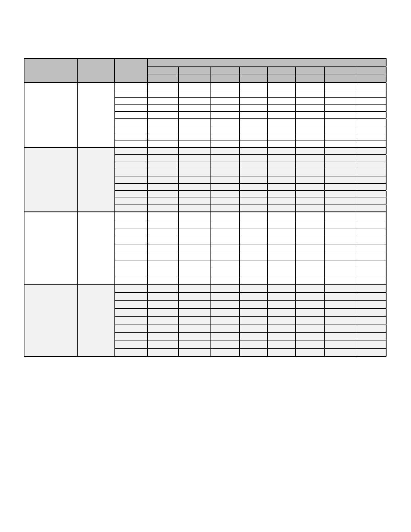
56
Airflow Tables - GM9S96
0.1
0.2
0.3
0.4 0.5
0.6
0.7 0.8
CFM CFM CFM
CFM
CFM CFM
CFM
CFM
F01
705 661 617
564
509 455
405
362
F02
1079 1055 1027 994 965 935
906 863
F03
915 881
846 814 780
737 695 652
F04^
887 855 823 790 751 705 666
608
F05
1135 1106 1078
1049
1021 994 965 933
F06
1189 1163 1138 1111 1085 1059
1032 1001
F07
1266 1243 1218 1197 1172 1148 1123
1099
F08
1313
1288
1261 1239 1215 1189 1165
1143
F09
1342 1324 1305 1280 1263 1239 1216
1193
F01
758 696 636 572 512 460 412 354
F02
1218 1178 1140 1100 1060 1016 977 937
F03
1164 1123 1084 1042 1003 960 920 871
F04^
1121
1083 1041
996 953 906
861 818
F05
902
851 801 746 689 637 585 542
F06
960
917
864
812 764 708 661
614
F07
1273 1240 1207
1171 1128 1089 1051
1012
F08
1335 1301
1266 1228 1192 1154 1118 1078
F09
1427 1390 1362 1327
1297 1260
1224 1193
F01 715 658 589 524 465 412 360 279
F02 1415 1385 1355
1322 1291
1255 1219 1186
F03 1388
1360 1325 1291
1259
1223 1191 1157
F04^ 1290 1252 1215 1182
1143 1107 1071 1032
F05 916 867 817
767 710 657 608 563
F06 985 940 892
842 797 746 693 649
F07 1118 1078
1037 992 952
910 863 822
F08 1191 1153
1114 1074 1034 993 951 911
F09 1471 1440 1409 1377 1347 1314 1283 1247
F01 1019
952 878 796 706 619 542 485
F02 1791 1743 1700 1663 1626 1583
1538 1489
F03 1625 1559 1512 1468 1425 1370 1325 1271
F04^
1537 1490 1447
1403 1354 1301 1247 1190
F05 1289 1234 1180 1122 1058 991 917 840
F06 1431 1375 1329
1283 1227 1169 1108 1043
F07 1836 1784
1741 1703 1664 1628 1585 1537
F08 1919 1890 1846 1807 1771 1735 1694 1650
F09 1952 1921 1885 1843 1804 1769 1731 1691
LOW STAGE COOLING AIFLOW
*M9S960803B*
Y/Y1
*M9S960603B*
Y/Y1
MODEL
THERMOSTAT
CALL
TAP #
EXTERNAL STATIC PRESSURE, (INCHES WATER COLUMN)
*M9S960403A*
Y/Y1
*M9S960804C*
Y/Y1
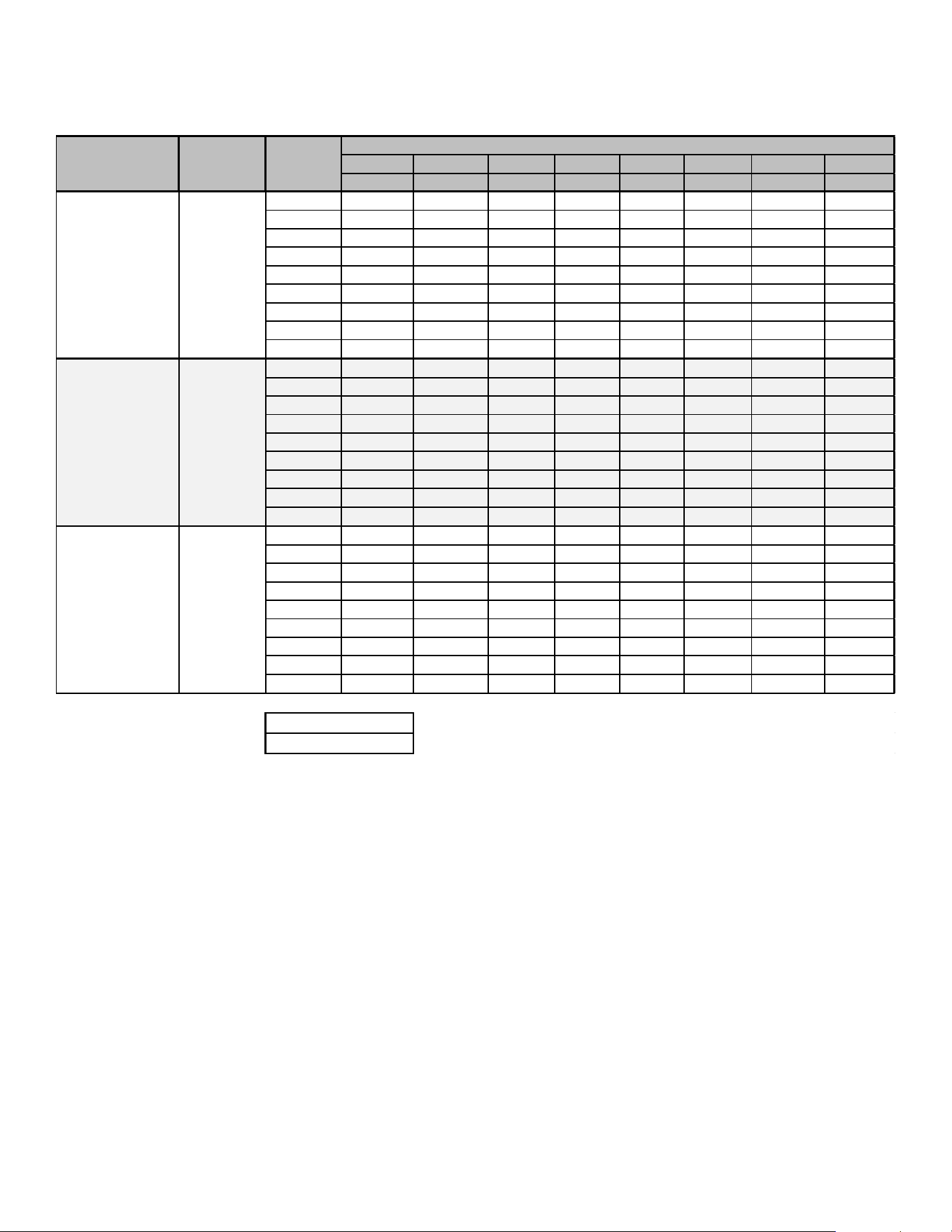
57
Airflow Tables - GM9S96
0.1 0.2 0.3 0.4
0.5
0.6 0.7 0.8
CFM CFM CFM CFM CFM CFM CFM
CFM
F01 1029
959
890 811 727 647 579
511
F02
1814
1766 1722 1679 1637 1595 1555 1511
F03 1893 1844 1803 1763 1723 1685 1641 1604
F04^
1738 1680 1637 1596 1554 1510 1469 1420
F05 1193 1135 1087 1016 986 950 880 805
F06
1421 1369 1323 1272 1222 1168 1108 1045
F07 1582 1536 1491 1445 1404 1358 1309 1255
F08 1962 1919 1889
1851 1816 1780 1743
1702
F09
2068 2024 1986
1947
1912
1873 1837 1797
F01 1008 934 855 779 702 628 557 493
F02 2026 1981 1929 1901 1858 1819 1773 1733
F03 1921 1879
1840 1791 1751 1705 1656
1610
F04^ 1804 1755 1710 1664 1619 1574
1526 1479
F05 1475
1421 1369 1314 1260
1207 1152 1097
F06 1626 1578 1522 1475 1427
1353 1328 1283
F07 1693
1639 1588 1542 1491
1437 1390 1340
F08 1775 1723 1674 1629 1580 1529 1484 1435
F09 2161
2122 2084 2048 2010 1973 1940 1914
F01 1118 1035 952
860 750 663 590 519
F02 2143 2095 2047 2002
1954 1891 1850 1802
F03 2025 1977 1930
1897 1848 1798 1750 1703
F04^ 1906 1877 1828 1778 1726 1674 1622 1568
F05
1220 1145 1070 995 952
907 811 725
F06 1684 1620 1561 1499 1438 1378 1318 1259
F07 1766 1712 1666 1612 1558 1506
1450 1395
F08 1863 1807
1754 1698 1642 1587 1532 1476
F09 2454
2396
2347
2296 2250
2202 2157 2113
LOW STAGE COOLING AIFLOW
MODEL
THERMOSTAT
CALL
TAP #
EXTERNAL STATIC PRESSURE, (INCHES WATER COLUMN)
NOTE:
^ Default speed
Y/Y1
*M9S960805C*
*M9S961005C*
*M9S961205D*
Y/Y1
Y/Y1
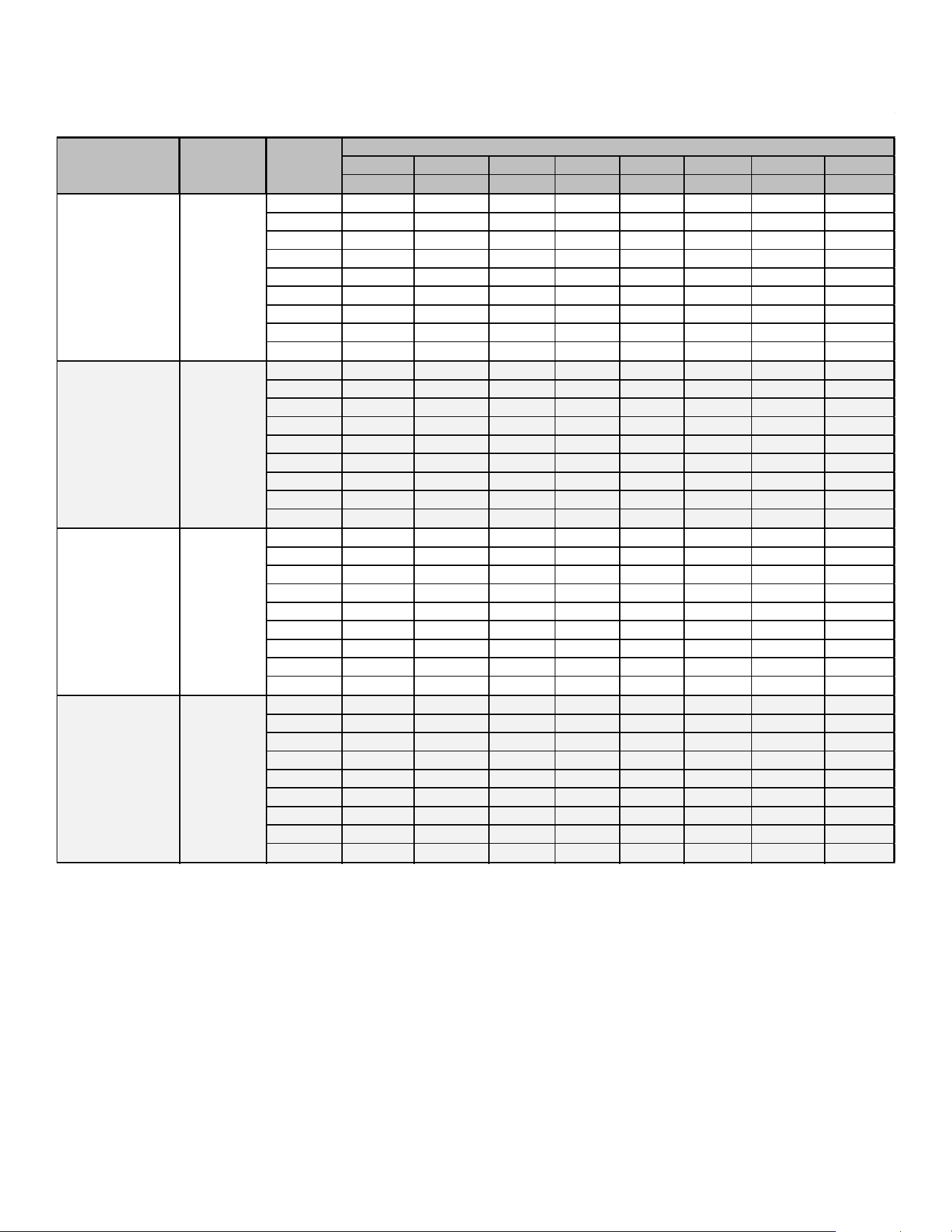
58
Airflow Tables - GM9S96
0.1 0.2 0.3 0.4 0.5 0.6 0.7 0.8
CFM CFM CFM CFM CFM CFM CFM CFM
F01 705 661 617 564 509 455 405 362
F02 1079 1055 1027 994 965 935 906 863
F03 915 881 846 814 780 737 695 652
F04 887 855 823 790 751 705 666 608
F05^ 1135 1106 1078 1049 1021 994 965 933
F06 1189 1163 1138 1111 1085 1059 1032 1001
F07 1266 1243 1218 1197 1172 1148 1123 1099
F08 1313 1288 1261 1239 1215 1189 1165 1143
F09 1342 1324 1305 1280 1263 1239 1216 1193
F01 758 696 636 572 512 460 412 354
F02 1218 1178 1140 1100 1060 1016 977 937
F03 1164 1123 1084 1042 1003 960 920 871
F04 1121 1083 1041 996 953 906 861 818
F05^ 902 851 801 746 689 637 585 542
F06 960 917 864 812 764 708 661 614
F07 1273 1240 1207 1171 1128 1089 1051 1012
F08 1335 1301 1266 1228 1192 1154 1118 1078
F09 1427 1390 1362 1327 1297 1260 1224 1193
F01 715 658 589 524 465 412 360 279
F02 1415 1385 1355 1322 1291 1255 1219 1186
F03 1388 1360 1325 1291 1259 1223 1191 1157
F04 1290 1252 1215 1182 1143 1107 1071 1032
F05^ 916 867 817 767 710 657 608 563
F06 985 940 892 842 797 746 693 649
F07 1118 1078 1037 992 952 910 863 822
F08 1191 1153 1114 1074 1034 993 951 911
F09 1471 1440 1409 1377 1347 1314 1283 1247
F01 1019 952 878 796 706 619 542 485
F02 1791 1743 1700 1663 1626 1583 1538 1489
F03 1625 1559 1512 1468 1425 1370 1325 1271
F04 1537 1490 1447 1403 1354 1301 1247 1190
F05^ 1289 1234 1180 1122 1058 991 917 840
F06 1431 1375 1329 1283 1227 1169 1108 1043
F07 1836 1784 1741 1703 1664 1628 1585 1537
F08 1919 1890 1846 1807 1771 1735 1694 1650
F09 1952 1921 1885 1843 1804 1769 1731 1691
HIGH STAGE COOLING AIFLOW
THERMOSTAT
CALL
TAP #
EXTERNAL STATIC PRESSURE, (INCHES WATER COLUMN)
Y2
*M9S960803B*
Y2
*M9S960804C*
Y2
*M9S960403A*
*M9S960603B*
Y2
MODEL
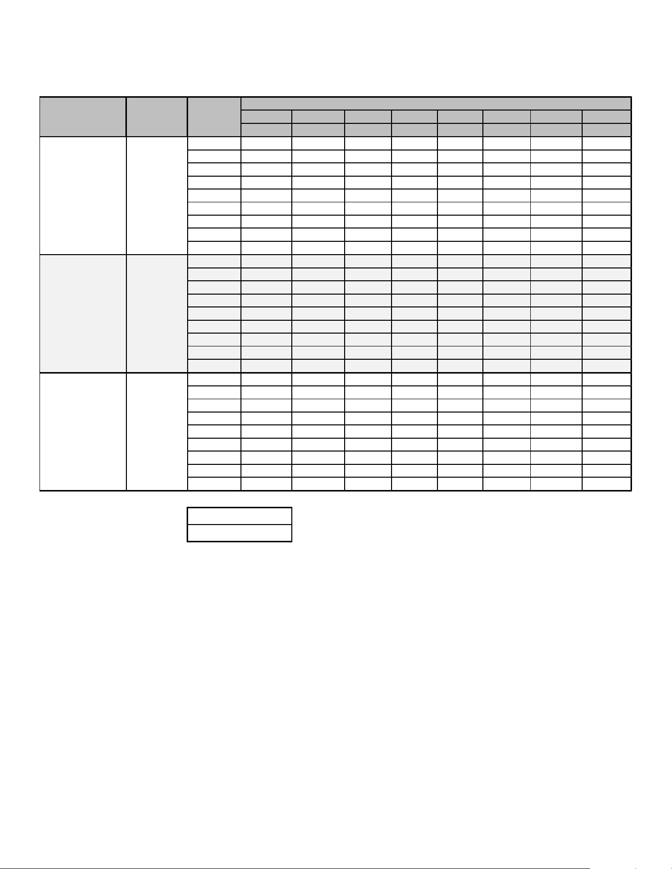
59
Airflow Tables - GM9S96
0.1 0.2 0.3 0.4
0.5
0.6 0.7
0.8
CFM
CFM CFM CFM CFM CFM CFM CFM
F01 1029 959 890 811
727 647
579
511
F02
1814 1766
1722 1679 1637 1595 1555 1511
F03 1893
1844 1803 1763 1723 1685 1641 1604
F04
1738
1680 1637 1596 1554 1510 1469 1420
F05^
1193 1135 1087 1016 986 950 880 805
F06
1421 1369
1323 1272 1222 1168 1108 1045
F07
1582 1536 1491 1445 1404 1358 1309 1255
F08 1962 1919 1889 1851 1816 1780 1743 1702
F09 2068
2024
1986 1947 1912 1873 1837 1797
F01
1008 934 855 779 702 628 557 493
F02 2026 1981 1929
1901 1858
1819 1773 1733
F03 1921 1879 1840
1791
1751 1705
1656 1610
F04 1804 1755 1710 1664 1619 1574 1526 1479
F05^ 1475 1421 1369 1314 1260 1207 1152 1097
F06 1626 1578
1522
1475 1427 1353 1328 1283
F07 1693 1639
1588 1542 1491 1437 1390 1340
F08 1775 1723 1674
1629 1580 1529 1484 1435
F09 2161
2122 2084 2048 2010 1973 1940 1914
F01 1118 1035 952 860 750
663 590 519
F02
2143 2095 2047
2002 1954 1891 1850 1802
F03 2025
1977 1930 1897 1848 1798 1750 1703
F04 1906 1877 1828 1778 1726 1674 1622 1568
F05^ 1220 1145 1070 995
952 907 811 725
F06 1684
1620 1561 1499 1438 1378 1318 1259
F07 1766
1712
1666 1612 1558 1506 1450 1395
F08 1863 1807
1754 1698 1642 1587 1532 1476
F09
2454 2396 2347 2296 2250 2202 2157 2113
HIGH STAGE COOLING AIFLOW
NOTE:
^ Default speed
THERMOSTAT
CALL
TAP #
EXTERNAL STATIC PRESSURE, (INCHES WATER COLUMN)
*M9S961205D*
Y2
*M9S960805C*
Y2
*M9S961005C*
MODEL
Y2
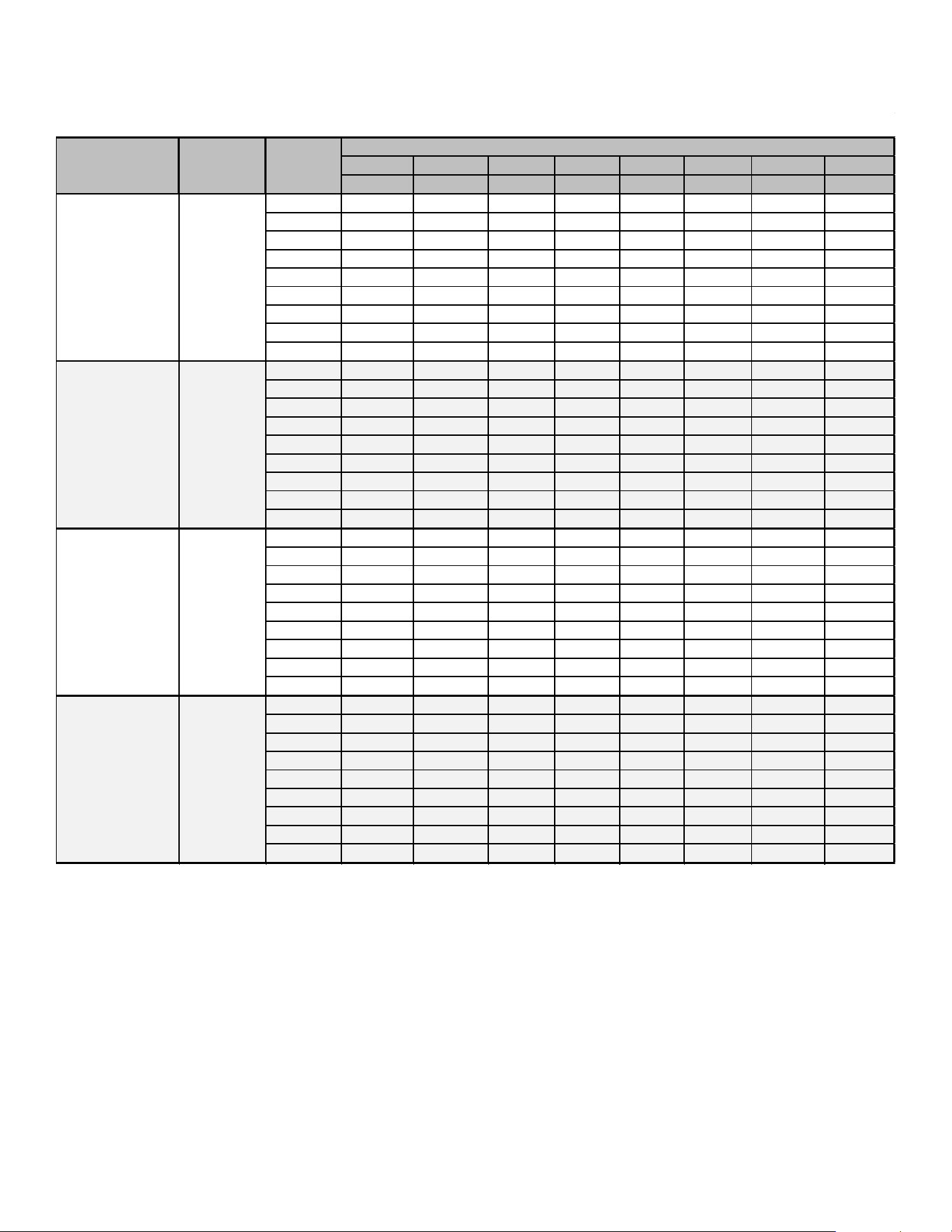
60
Airflow Tables - GM9S96
0.1
0.2
0.3 0.4 0.5 0.6 0.7 0.8
CFM
CFM CFM CFM CFM CFM CFM
CFM
F01 705 661 617 564
509
455 405 362
F02
1079 1055 1027 994 965
935
906 863
F03
915 881 846 814 780 737
695 652
F04
887 855 823 790 751 705
666 608
F05
1135 1106 1078 1049 1021
994
965 933
F06 1189 1163 1138
1111 1085
1059 1032
1001
F07 1266 1243 1218
1197 1172
1148 1123
1099
F08
1313 1288
1261 1239 1215 1189 1165
1143
F09 1342
1324
1305 1280 1263 1239 1216
1193
F01
758 696
636 572 512 460 412
354
F02 1218 1178
1140 1100 1060 1016 977 937
F03 1164 1123
1084 1042 1003 960 920
871
F04
1121
1083 1041 996
953 906 861 818
F05 902
851 801 746 689 637 585 542
F06
960 917
864 812 764 708
661
614
F07 1273 1240 1207 1171 1128
1089 1051
1012
F08 1335
1301 1266
1228 1192 1154 1118 1078
F09
1427 1390 1362 1327 1297
1260 1224 1193
F01 715 658 589 524 465 412 360 279
F02 1415 1385 1355 1322 1291 1255
1219 1186
F03 1388 1360
1325 1291 1259
1223 1191
1157
F04
1290 1252
1215 1182
1143
1107 1071 1032
F05 916 867 817 767 710
657 608 563
F06 985 940 892 842
797 746 693 649
F07 1118 1078
1037
992 952 910 863 822
F08 1191 1153 1114
1074 1034 993 951 911
F09
1471 1440 1409 1377 1347
1314 1283 1247
F01 1019 952 878 796 706
619 542 485
F02 1791 1743 1700 1663 1626
1583 1538 1489
F03 1625 1559 1512 1468 1425 1370 1325 1271
F04 1537 1490 1447 1403 1354 1301 1247 1190
F05 1289 1234 1180 1122 1058 991 917 840
F06 1431 1375 1329 1283 1227 1169 1108 1043
F07 1836 1784 1741 1703 1664 1628 1585 1537
F08 1919 1890 1846 1807 1771 1735 1694 1650
F09 1952 1921 1885 1843 1804 1769 1731 1691
CIRCULATION AIRFLOW
G
*M9S960803B*
G
MODEL
TAP #
EXTERNAL STATIC PRESSURE, (INCHES WATER COLUMN)
G
G
THERMOSTAT
CALL
*M9S960403A*
*M9S960603B*
*M9S960804C*
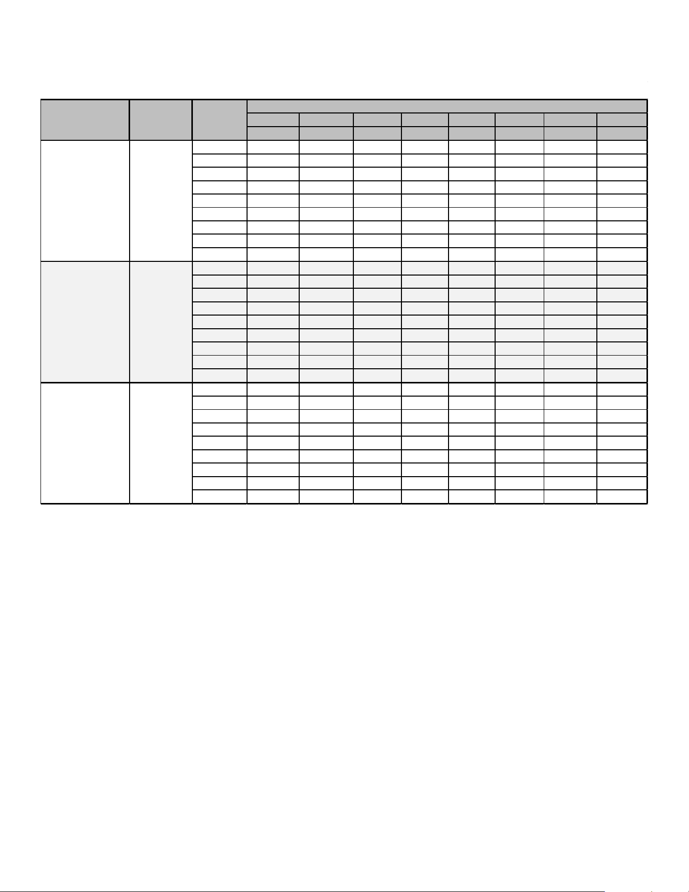
61
Airflow Tables - GM9S96
0.1
0.2 0.3 0.4 0.5 0.6
0.7 0.8
CFM CFM CFM CFM CFM CFM
CFM CFM
F01
1029 959 890 811 727 647 579 511
F02 1814 1766
1722 1679 1637 1595 1555 1511
F03 1893
1844 1803 1763 1723 1685 1641 1604
F04
1738 1680 1637 1596 1554 1510 1469 1420
F05
1193 1135 1087 1016 986 950 880 805
F06 1421 1369 1323 1272
1222
1168 1108 1045
F07 1582 1536 1491 1445 1404 1358 1309 1255
F08 1962 1919 1889 1851 1816 1780 1743 1702
F09 2068 2024 1986 1947 1912 1873 1837 1797
F01 1008 934 855 779 702 628 557
493
F02
2026
1981 1929 1901
1858 1819
1773 1733
F03 1921 1879 1840 1791 1751 1705 1656 1610
F04 1804 1755 1710 1664 1619 1574 1526 1479
F05 1475 1421 1369
1314 1260
1207 1152
1097
F06
1626 1578 1522
1475 1427 1353 1328 1283
F07 1693 1639 1588 1542 1491
1437 1390 1340
F08 1775 1723 1674 1629 1580 1529
1484 1435
F09 2161 2122 2084 2048 2010 1973 1940 1914
F01 1118 1035 952 860 750 663 590 519
F02 2143 2095 2047 2002 1954 1891 1850 1802
F03 2025 1977 1930 1897 1848 1798 1750 1703
F04 1906 1877 1828 1778 1726 1674 1622 1568
F05 1220 1145 1070 995 952 907 811 725
F06 1684 1620 1561 1499 1438 1378 1318 1259
F07 1766 1712 1666 1612 1558 1506 1450 1395
F08 1863 1807 1754 1698 1642 1587 1532 1476
F09 2454 2396 2347 2296 2250 2202 2157 2113
CIRCULATION AIRFLOW
*M9S960805C*
MODEL
G
TAP #
EXTERNAL STATIC PRESSURE, (INCHES WATER COLUMN)
THERMOSTAT
CALL
G
*M9S961205D*
G
*M9S961005C*
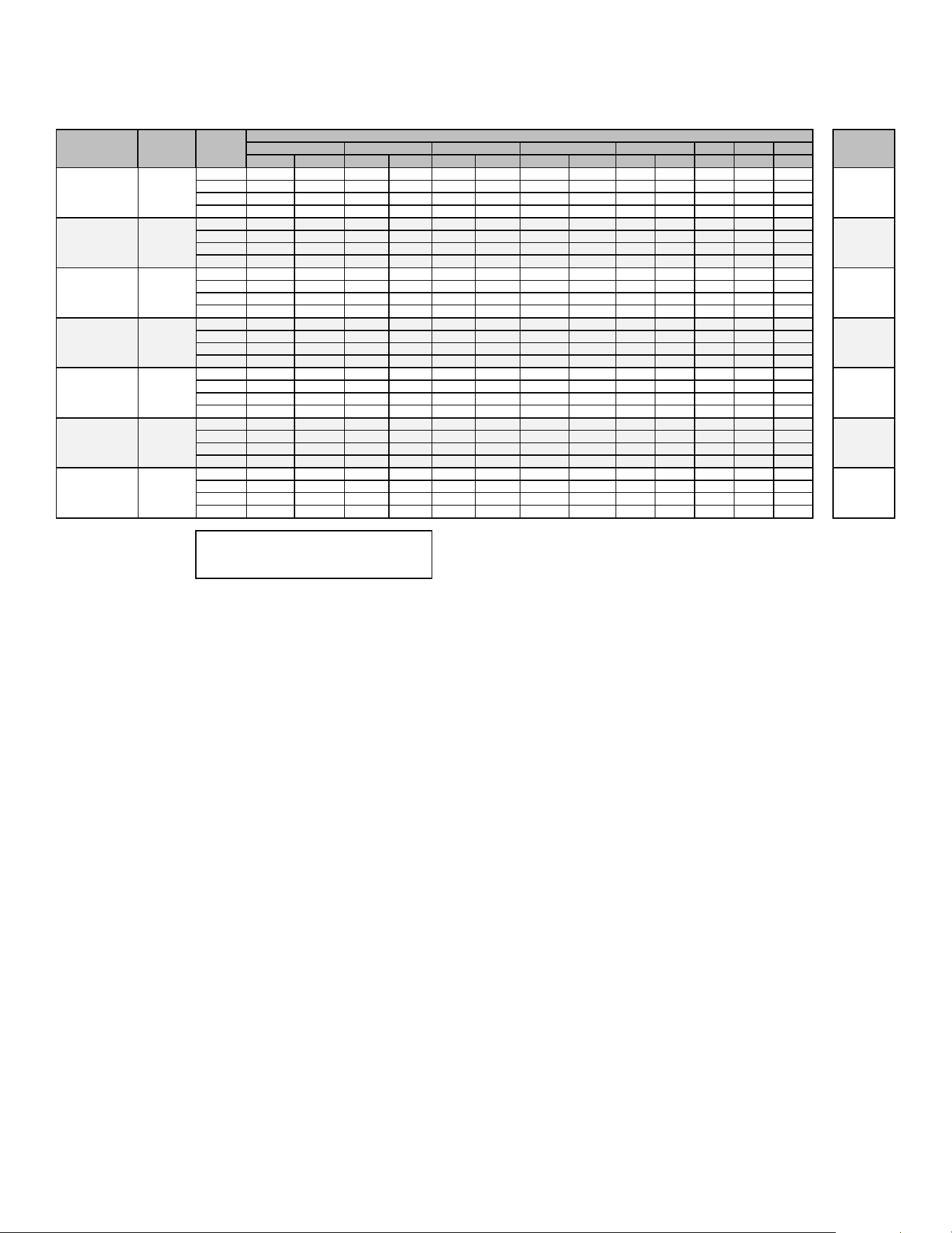
62
Airflow Tables - GM9S96
0.6 0.7 0.8
CFM RISE
CFM
RISE CFM RISE CFM RISE CFM RISE CFM CFM CFM
F01^^ 705
50 661 54
617 N/A 564 N/A 509 N/A 455 405 362
F02^ 1079 33 1055 34 1027 35 994 36 965 37 935 906 863
F03 915 39 881 40 846 42 814 44 780 46 737 695 652
F04 887 40 855 42 823 43 790 45 751 47 705 666 608
F01^^ 758 N/A 696 N/A 636 N/A 572 N/A 512 N/A 460 412 354
F02^ 1218 44 1178 45 1140 47 1100 48 1060 50 1016 977 937
F03 1164 46 1123 47 1084 49 1042 51 1003 53 960 920 871
F04 1121 48 1083 49 1041 51 996 54 953 56 906 861 818
F01^^ 715 N/A 658 N/A 589 N/A 524 N/A 465 N/A 412 360 279
F02^ 1415 50 1385 51 1355 52 1322 54 1291 55 1255 1219 1186
F03 1388 51 1360 52 1325 54 1291 55 1259 57 1223 1191 1157
F04 1290 55 1252 57 1215 59 1182 60 1143 62 1107 1071 1032
F01^^ 1019 N/A 952 N/A 878 N/A 796 N/A 706 N/A 619 542 485
F02^ 1791 40 1743 41 1700 42 1663 43 1626 44 1583 1538 1489
F03 1625 44 1559 46 1512 47 1468 48 1425 50 1370 1325 1271
F04 1537 46 1490 48 1447 49 1403 51 1354 53 1301 1247 1190
F01^^ 1029 N/A 959 N/A 890 N/A 811 N/A 727 N/A 647 579 511
F02^ 1814 39 1766 40 1722 41 1679 42 1637 43 1595 1555 1511
F03 1893 38 1844 39 1803 39 1763 40 1723 41 1685 1641 1604
F04 1738 41 1680 42 1637 43 1596 45 1554 46 1510 1469 1420
F01^^ 1008 N/A 934 N/A 855 N/A 779 N/A 702 N/A 628 557 493
F02^ 2026 44 1981 45 1929 46 1901 47 1858 48 1819 1773 1733
F03 1921 46 1879 47 1840 48 1791 50 1751 51 1705 1656 1610
F04 1804 49 1755 51 1710 52 1664 53 1619 55 1574 1526 1479
F01^^ 1118 N/A 1035 N/A 952 N/A 860 N/A 750 N/A 663 590 519
F02^ 2143 50 2095 51 2047 52 2002 53 1954 55 1891 1850 1802
F03 2025 53 1977 54 1930 55 1897 56 1848 58 1798 1750 1703
F04^^ 1906 56 1877 57 1828
58 1778 60 1726 62 1674 1622 1568
HEATING AIFLOW
^^NOT RECOMMENDED FOR HEATING
NOTE:
TAP #
EXTERNAL STATIC PRESSURE, (INCHES WATER COLUMN)
0.1
0.2
0.3
0.4
0.5
^DEFAULT & RECOMMENDED
*M9S960403A*
MODEL
THERMOSTAT
CALL
35-65
25-55
TEMP RANGE
25-55
W/W1
25-55
30-60
35-65
W/W1
*M9S960603B*
W/W1
*M9S960803B*
W/W1
*M9S960804C*
W/W1
*M9S960805C*
W/W1
*M9S961005C*
W/W1
*M9S961205D*
35-65
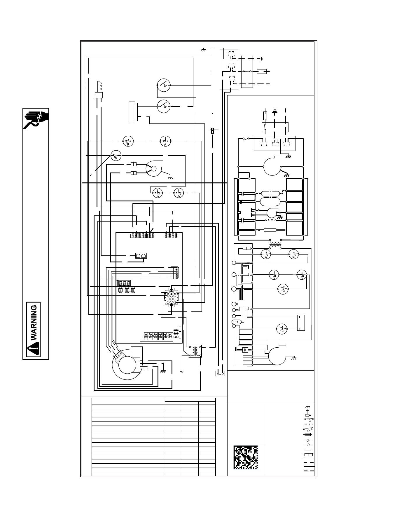
63
Wiring Diagram *M9S92/*M9S96/*C9S96
Wiring is subject to change. Always refer to the wiring diagram on the unit for the most up-to-date wiring.
HIGH VOLTAGE!
Disconnect ALL power before servicing or installing this unit. Multiple
power sources may be present. Failure to do so may cause property
damage, personal injury or death.
G
N
G
N
D
R
D
GN
24
VAC
115
VAC
G
N
D
GRD
0
1
4
0
F
0
2
6
2
6
-
A
BK
E
A
C
H
U
M
I
D
I
F
I
E
R
ID
N
E
U
T
R
A
L
W
IR
IN
G
T
O
U
N
I
T
L
INTEGRATED CONTROL MODULE
H
O
T
S
U
R
F
A
C
E
G
N
D
B
L
W
R
N
E
U
T
R
A
L
W
A
R
N
IN
G
:
G
R
O
U
N
D
E
D
.
O
V
E
R
C
U
R
R
E
N
T
P
R
O
T
E
C
T
IO
N
D
E
V
I
C
E
M
U
S
T
B
E
P
R
O
P
E
R
L
Y
S
W
I
T
C
H
N
E
U
T
R
A
L
E
L
E
C
T
R
O
N
I
C
A
I
R
IG
N
I
N
D
D
I
S
C
O
N
N
E
C
T
F
S
P
O
L
A
R
IZ
E
D
A
N
D
N
E
U
T
R
A
L
L
I
N
E
N
E
U
T
R
A
L
J
U
N
C
T
IO
N
B
O
X
B
L
W
R
I
N
D
L
O
N
I
N
D
O
O
R
A
I
R
C
L
E
A
N
E
R
H
U
M
D
O
O
R
N
E
U
T
R
A
L
INTEGRATED CONTROL MODULE
T
O
1
1
5
V
A
C
/
1
Ø
/6
0
H
Z
P
O
W
E
R
S
U
P
P
L
Y
W
IT
H
1
1
5
V
A
C
H
U
M
-
O
U
T
I
G
N
I
T
E
R
C
I
R
C
U
L
A
T
O
R
B
E
F
O
R
E
S
E
R
V
IC
IN
G
.
F
L
A
M
E
S
E
N
S
O
R
D
IS
C
O
N
N
E
C
T
P
O
W
E
R
L
I
N
E
G
N
D
BR
WH
GY
YL
PK
GY
L
IM
I
T
C
O
N
T
R
O
L
A
U
X
I
L
I
A
R
Y
A
U
T
O
R
E
S
E
T
P
K
W
A
R
N
I
N
G
:
D
I
S
C
O
N
N
E
C
T
40 VA
TRANSFORMER
N
G
C
S
E
N
S
O
R
F
L
A
M
E
1
R
O
L
L
O
U
T
S
W
I
T
C
H
S
O
M
E
U
N
I
T
S
M
A
Y
H
A
V
E
T
O
U
N
I
T
M
U
S
T
B
E
P
U
RD
A
N
D
G
R
O
U
N
D
E
D
.
JUNCTION BOX
WH
BL
B
R
N
O
L
I
M
IT
C
O
N
T
R
O
L
A
U
T
O
R
E
S
E
T
P
R
I
M
A
R
Y
W
H
1
L
B
K
ID
B
L
O
W
E
R
P
R
E
S
S
U
R
E
S
W
I
T
C
H
S
E
R
V
I
C
I
N
G
.
W
IR
IN
G
PK
RD
L
N
D
O
O
R
O
P
E
N
)
(
O
P
E
N
W
H
E
N
D
O
O
R
S
W
I
T
C
H
C
O
M
P
A
R
T
M
E
N
T
B
L
O
W
E
R
G
N
D
BLOWER
CIRCULATOR
Ø
/6
0
H
Z
D
IS
C
O
N
N
E
C
T
G
A
S
V
A
L
V
E
O
V
E
R
C
U
R
R
E
N
T
C
O
N
N
E
C
T
O
R
2
C
IR
C
U
IT
G
N
D
WH
CHASSIS
GROUND
I
G
N
I
T
E
R
S
U
R
F
A
C
E
H
O
T
2
YL
C
B
L
O
W
E
R
D
R
A
F
T
I
N
D
U
C
E
D
BK
B
L
O
W
E
R
C
O
M
P
A
R
T
M
E
N
T
1
1
5
V
A
C
/
1
BK
ECM MTR
HARNESS
POWER BEFORE
BK
T
O
P
O
W
E
R
S
U
P
P
L
Y
W
I
T
H
B
U
R
N
E
R
C
O
M
P
A
R
T
M
E
N
T
P
R
O
T
E
C
T
I
O
N
D
E
V
IC
E
PROPERLY PO
LARIZED
SWITCH (PRESS.)
FIELD SPLICE
FIELD GND
EQUIPMENT G
ND
INTERNAL TO
PROT. DEVICE
INTEGRATED CONTROL
PLUG CONNE
CTION
SWITCH (TEMP.)
JUNCTION
LOW VOLTAGE (24V)
OVERCURRENT
TERMINAL
IGNITER
LOW VOLTAGE FIELD
HI VOLTAGE (115V)
HI VOLTAGE FIELD
NOTES:
1. SET HEAT ANTICIPATOR ON ROOM THERMOSTAT AT 0.7 AMPS.
2. MANUFACTURER'S SPECIFIED REPLACEMENT PARTS MUST BE USED
WHEN SERVICING.
3. IF ANY OF THE ORIGINAL WIRE AS SUPPLIED WITH THE FURNACE
MUST BE REPLACED IT MUST BE REPLACED WITH WIRING MATERIAL
HAVING A TEMPERATURE RATING OF AT LEAST 105
C. USE COPPER
CONDUCTORS ONLY.
4. UNIT MUST BE PERMANENTLY GROUNDED AND CONFORM TO N.E.C.
AND LOCAL CODES.
5. TO RECALL THE LAST 6 FAULTS, MOS
T RECENT TO LEAST RECENT,
DEPRESS SWITCH FOR MORE THAN 2 SECONDS WHILE IN STANDBY
(NO THERMOSTAT INPUTS)
COLOR CODES:
PK PINK
BR BROWN
WH WHITE
BL BLUE
GY GRAY
RD RED
YL YELLOW
OR ORANGE
PU PURPLE
GN GREEN
BK BLACK
1
2
3
4
5
6
7
8
9
10
11
12
READ CODES FROM LEFT TO RIGHT
EAC-H
XFMR-H
CIRC-H
LINE-H
E20
E39
E2
E1
E15
E8
E5
E4
E3
E7
E6
LEFT
CENTER
RIGHT
SW
3
3
1
3
1
3
SW
1
R
2
2
3
S
W
2
6
R
2
2
6
TWIN DEHUM 24V HUM
E21
E34
E24
W/W1 R G R Y/Y1 Y2
RD
BL
RD
YL
YL
BK
BK
BK
WH
WH
WH
GY
OR
GN
PU
PU
PU
NEUT2
NEUT1
CIRC-N
EAC-N
HUM-N
XFMR-N
LINE-N
G
N
D
M
I
C
R
O
T
O
TR (7)
G
C
C
TH (3)
24V THERMOSTAT CONNECTIONS N.E.C. CLASS 2 WIRE
GAS VALVE
TRANS
FORMER
HLI (8)
Y
2
Y
1
R
L
O
(6
)
O
MV (10)
W
1
R
M
A
N
U
A
L
R
E
S
E
T
R
O
L
L
O
U
T
L
IM
IT
S
W
IT
C
H
P
R
E
S
S
.
S
W
T
I
C
H
.
C
D
E
H
U
M
PS1(5)
A
U
T
O
R
E
S
E
T
P
R
IM
A
R
Y
L
IM
IT
2
4
V
A
C
NO
HI
MVC (11)
BLWR
AIR
INDOOR
CIRCULATOR
R
TO
MICRO
TO
T
O
+
V
D
C
40 VA
INTERGRATED CONTROL MODULE
RLI (12)
A
U
T
O
R
E
S
E
T
A
U
X
L
I
M
IT
HLO (1)
Seven Segment Display
Error Code Status
Seg#3 Seg#2 Seg#1
Internal Faults or IRQ Loss
EEE
Lockout Due to Excessive Retries or Recycles E E 0
Pressure Switch Stuck Closed E E 1
Pressure Switch Open
E E 2
Open High Limit Switch E E 3
Flame Detected When no Flame Should be Present E E 4
Open Fuse E E 5
Low Flame Signal E E 6
Ignitor Relay Fault E E L
Reversed Line Polarity or Grounding Error E E A
Internal Gas Valve Error
E E b
External Gas Valve Error E E C
Open Rollout Switch E 1 1
Ignitor Ope
n
E E n
Inducer Relay Error E E j
TWIN Error E E H
RD
C
2
M
I
1
2
RD
BK
BK
WH
WH
WH
WH
Grounding Error E 1 0
5
3 41 2
R
D
B
K
O
R
B
L
Y
L
R
D
B
L
O
R
B
K
Y
L
T
1
T
2
T
3
T
4
T
5
C
O
M
R
D
N
O
C
GY
F
R
O
N
T
C
O
V
E
R
P
R
E
S
S
U
R
E
S
W
IT
C
H
C
NO
F
R
O
N
T
C
O
V
E
R
P
R
E
S
S
U
R
E
S
W
IT
C
H
YL
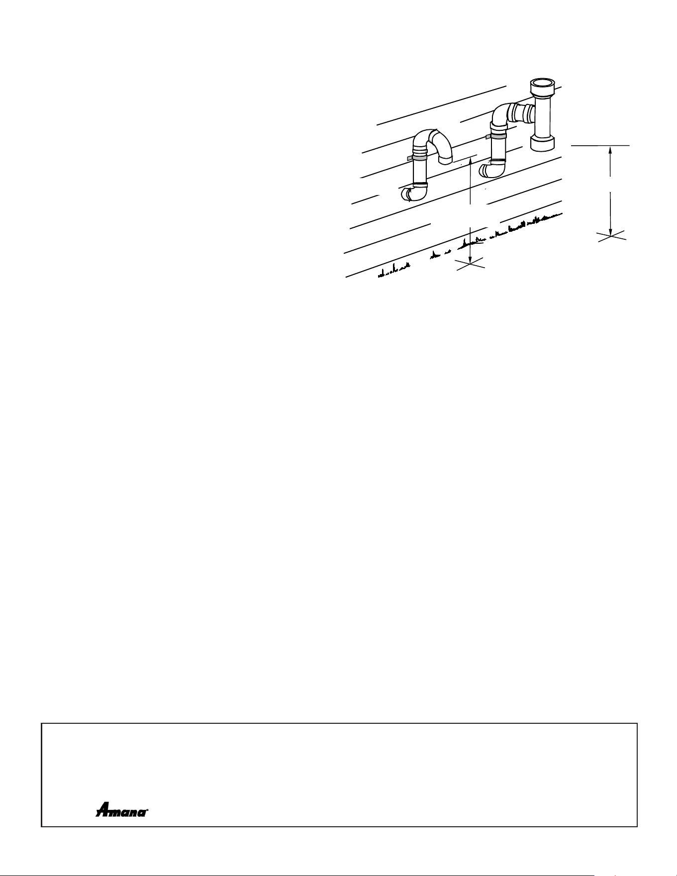
64
SPECIAL INSTRUCTIONS FOR PRODUCTS INSTALLED IN THE STATE OF MASSACHUSETTS
For all side wall horizontally vented gas fueled equipment installed in every dwelling, building or structure used in whole or
in part for residential purposes, including those owned or
operated by the Commonwealth and where the side wall
exhaust vent termination is less than seven (7) feet above
nished grade in the area of the venting, including but not
limited to decks and porches, the following requirements
shall be satised:
1. INSTALLATION OF CARBON MONOXIDE DETECTORS.
At the time of installation of the side wall horizontal vented
gas fueled equipment, the installing plumber or gastter shall
observe that a hard wired carbon monoxide detector with an
alarm and battery back-up is installed on the oor level where
the gas equipment is to be installed. In addition, the installing
plumber or gastter shall observe that a battery operated
or hard wired carbon monoxide detector with an alarm is
installed on each additional level of the dwelling, building or
structure served by the side wall horizontal vented gas fueled
equipment. It shall be the responsibility of the property owner
to secure the services of qualied licensed professionals for
the installation of hard wired carbon monoxide detectors
a. In the event that the side wall horizontally vented gas fueled equipment is installed in a crawl space or an attic, the hard wired
carbon monoxide detector with alarm and battery back-up may be installed on the next adjacent oor level.
b. In the event that the requirements of this subdivision can not be met at the time of completion of installation, the owner shall have
a period of thirty (30) days to comply with the above requirements; provided, however, that during said thirty (30) day period, a
battery operated carbon monoxide detector with an alarm shall be installed.
2. APPROVED CARBON MONOXIDE DETECTORS. Each carbon monoxide detector as required in accordance with the above provisions
shall comply with NFPA 720 and be ANSI/UL 2034 listed and IAS certied.
3. SIGNAGE. A metal or plastic identication plate shall be permanently mounted to the exterior of the building at a minimum height of eight
(8) feet above grade directly in line with the exhaust vent terminal for the horizontally vented gas fueled heating appliance or equipment.
The sign shall read, in print size no less than one-half (1/2) inch in size, “GAS VENT DIRECTLY BELOW. KEEP CLEAR OF ALL
OBSTRUCTIONS”.
4. INSPECTION. The state or local gas inspector of the side wall horizontally vented gas fueled equipment shall not approve the
installation unless, upon inspection, the inspector observes carbon monoxide detectors and signage installed in accordance with the
provisions of 248 CMR 5.08(2)(a)1 through 4.
EXEMPTIONS
The following equipment is exempt from 248 CMR 5.08(2)(a)1 through 4:
1. 1. The equipment listed in Chapter 10 entitled “Equipment Not Required To Be Vented” in the most current edition of NFPA 54 as
adopted by the Board; and
2. 2. Product Approved side wall horizontally vented gas fueled equipment installed in a room or structure separate from the dwelling,
building or structure used in whole or in part for residential purposes.
c. MANUFACTURER REQUIREMENTS - GAS EQUIPMENT VENTING SYSTEM PROVIDED. When the manufacturer of Product
Approved side wall horizontally vented gas equipment provides a venting system design or venting system components with the
equipment, the instructions provided by the manufacturer for installation of the equipment and the venting system shall include:
3. Detailed instructions for the installation of the venting system design or the venting system components; and
4. A complete parts list for the venting system design or venting system.
d. MANUFACTURER REQUIREMENTS - GAS EQUIPMENT VENTING SYSTEM NOT PROVIDED. When the manufacturer of a
Product Approved side wall horizontally vented gas fueled equipment does not provide the parts for venting the ue gases, but
identies “special venting systems”, the following requirements shall be satised by the manufacturer:
5. The referenced “special venting system” instructions shall be included with the appliance or equipment installation instructions; and
6. The “special venting systems” shall be Product Approved by the Board, and the instructions for that system shall include a parts list and
detailed installation instructions.
e. A copy of all installation instructions for all Product Approved side wall horizontally vented gas fueled equipment, all venting
instructions, all parts lists for venting instructions, and/or all venting design instructions shall remain with the appliance or
equipment at the completion of the installation.
VENT/FLUE
TEE
COMBUSTION
AIR INTAKE.
DISTANCE BETWEEN
COMBUSTION AIR
INTAKE AND GRADE
DISTANCE BETWEEN
VENT AND GRADE
19001 Kermier Rd., Waller, TX 77484
www.goodmanmfg.com • www.amana-hac.com
© 2019-2021 Goodman Manufacturing Company, L.P.
Brand is a registered trademark of Maytag Corporation or its related companies and is used under license. All rights reserved.
NOTE: SPECIFICATIONS AND PERFORMANCE DATA LISTED HEREIN ARE SUBJECT TO CHANGE WITHOUT NOTICE.
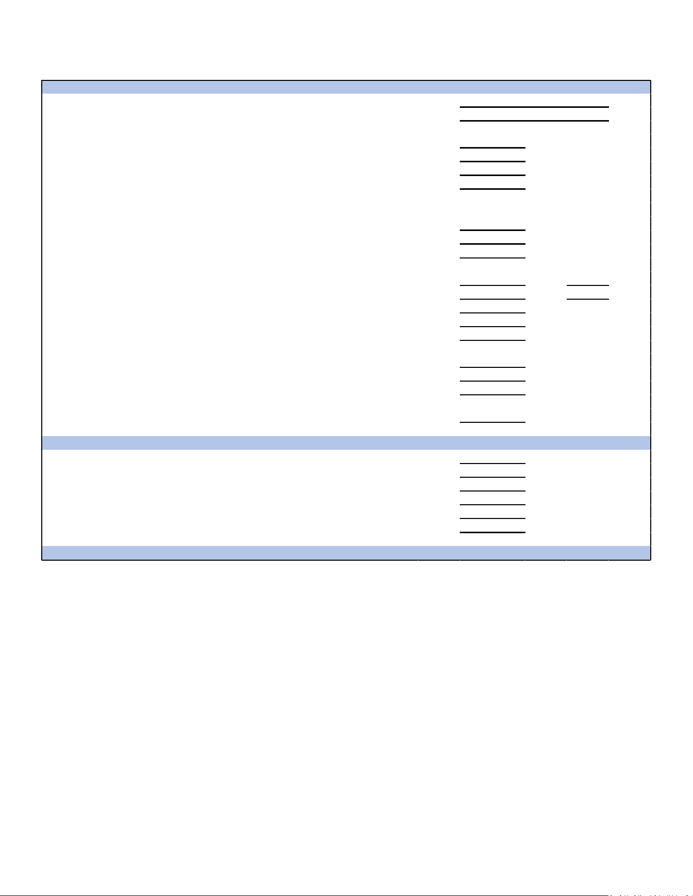
65
Start-Up Checklist
Furnace
ELECTRICAL
Line Voltage (Measure L1 to N and N to Ground Voltage) L - N
N - G
Secondary Voltage (Measure Transformer Output Voltage) R - C
Blower Amps
BLOWER EXTERNAL STATIC PRESSURE
Return Air Static Pressure IN. W.C.
Supply Air Static Pressure IN. W.C.
Total External Static Pressure (Ignoring +/- from the reading above, add total here) IN. W.C.
TEMPERATURES
Return Air Temperature (Dry bulb / Wet bulb) DB °F WB °F
DB °F WB °F
Heating Supply Air Temperature DB °F
Temperature Rise DB °F
Delta T (Difference between Supply and Return Temperatures) DB °F
GAS PRESSURES
Gas Inlet Pressure IN. W.C.
Gas Manifold Pressure (Low Fire) IN. W.C.
Gas Manifold Pressure (High Fire) IN. W.C.
Gas Type (NG) = Natural Gas / (LP) = Liquid Propane
Additional Checks
Check wire routings for any rubbing
Check for kinked pressure switch tubing.
Check flue elbow for alignment and clamp tightness.
Check screw tightness on blower wheel.
Check factory wiring and wire connections.
Check product for proper clearances as noted by installtion instructions
°F to °C formula: (°F - 32) divided by 1.8 = °C °C to °F formula: (°C multiplied by 1.8) + 32 = °F
Model Number
Serial Number
Cooling Supply Air Temperature (Dry bulb / Wet bulb)

66
THIS PAGE LEFT INTENTIONALLY BLANK.

67
THIS PAGE LEFT INTENTIONALLY BLANK.
68
19001 Kermier Rd., Waller, TX 77484
www.goodmanmfg.com • www.amana-hac.com
© 2021 Goodman Manufacturing Company, L.P.
Brand is a registered trademark of Maytag Corporation or its related companies
and is used under license. All rights reserved.
CUSTOMER FEEDBACK
We are very interested in all product comments.
Please ll out the feedback form on one of the following links:
Goodman® Brand Products: (hp://www.goodmanmfg.com/about/contact-us).
Amana® Brand Products: (hp://www.amana-hac.com/about-us/contact-us).
You can also scan the QR code on the right for the product brand
you purchased to be directed to the feedback page.
PRODUCT REGISTRATION
Thank you for your recent purchase. Though not required to get the protecon of
the standard warranty, registering your product is a relavely short process, and
entles you to addional warranty protecon, except that failure by California and
Quebec residents to register their product does not diminish their warranty rights.
For Product Registraon, please register as follows:
Goodman® Brand products: (hps://www.goodmanmfg.com/product-registraon).
Amana® Brand products: (hp://www.amana-hac.com/product-registraon)
You can also scan the QR code on the right for the product brand
you purchased to be directed to the Product Registraon page.
GOODMAN® BRAND
AMANA® BRAND
AMANA® BRAND
GOODMAN® BRAND